WORKSHOP MANUAL. Garden Tractor: EF 95 - EF EF OM 95 - OM OM 125
|
|
|
- Roderick Walton
- 5 years ago
- Views:
Transcription

1 WORKSHOP MANUAL Garden Tractor: EF 95 - EF EF OM 95 - OM OM 125
2 2 Workshop manual
3 1 Foreword General Safety instructions Maintenance and care Maintenance table Lubricating plan Front axle Steering Front and rear wheels Tensioning pulley rocker / pivoting and bearing points Oil change Air filter / spark plug Tyre pressure Hydrostatic transmission Starter battery (12V / 17 Ah) Troubleshooting plan Table troubleshooting plan Fault display and fault elimination Disassembly Bonnet Discharge channel Mowing implement Disassembling the mowing implement Replacing the blade Replacing V-Belt mowing implement Replacing the bearing (blade change) Replacing the tensioning pulley Disassembling the blade brake clutch Replacing the mowing implement feeler rollers Steering Disassembling the steering sector Disassembling the steering column Replacing the tie rod Propulsion Removing the floor cover of the vehicle frame
4 4.5.2 Removing the propulsion belt Disassembling tensioning pulleys and idler pulleys Electrical grass catcher emptying Electric system Replacing headlight bulb Starter battery Ignition/starter switch Removing the start relay Removing the relay Fuses Level buzzer / level switch Control panel control elements Transmission switch Circuit diagrams Lawn tractor with rear discharge and electronic system Lawn tractor with rear discharge without electronic system Adjustment work Mowing implement adjustment Grass catcher Brake adjustment Propulsion pedals Fine adjustment of the steering Steering sector adjustment Torque setting
5 1 Foreword This handbook contains all the information required for maintenance and repair of Efco and Oleo-Mac lawn tractors. The individual working processes are explained with comprehensive descriptions and illustrations. Here, we do not discuss work that can be done without special knowledge (such as changing wheels). During the disassembly and assembly work, ensure that you follow the instructions for removal/installation. All the information, illustrations, guidelines and descriptions contained in this document comply with the latest state of the data that was available for the product at the time of going to press. Emak reserves the right to make changes, at any time and without prior notice, without obligations of any kind for the company. The contents of this document may only be reproduced with written approval from Emak. 5
6 2 General 2.1 Safety instructions Workshop manual Working on the machine does not usually represent a specific hazard. An exception is the work that involves mechanical components. These activities should be carried out with the caution and attention that is usual for this type of work. In addition to observing the usual accident-prevention regulations that are typical for all mechanical workshops,we recommend: Carry out maintenance, service and repair work only when the engine is switched off and cool. Prior to starting work, remove the ignition key and disconnect the negative terminal of the battery. Wear suitable protective gloves when you handle blades and sheet-metal parts. Avoid petrol leaking. Wipe up leaked petrol. Smoking prohibited in the vicinity of engine and tank. Secure the tractor such that persons cannot be injured from inadvertent actions. CAUTION! Risk of accidents! Observe the safety instructions in the operating and engine instructions, and the safety instructions on the unit. Trailer: The total weight of a trailer pulled by the tractor should not be higher than 50% of the tractor weight including driver. For this tractor, the total weight of the trailer should not be higher than 250 kg. The maximum towed and drawbar load is 40 kg. 6
7 3 Maintenance and care 3.1 Maintenance table Caution! Risk of accidents! Carry out maintenance, service and repair work only when the motor is switched off and cool. Prior to starting work, remove the ignition key and disconnect the negative terminal of the battery. Before every use After the first 5 operating hours Every 10 operating hours Every 25 operating hours Every 50 operating hours or yearly Every 100 operating hours Checking the engine oil level 1) X X X Changing the engine oil 1) - X - - X - Replacing the oil filter (if installed) 1) X Cleaning the air filter 1) X - - Replacing the air filter 1) X - Checking the spark plug 1) X - Checking the brake - X X Checking the tyre pressure - X X Checking the mowing blade - X X Checking the adjustment of the mowing implement Checking the hydrostatic transmission oil level - X X X - Checking for loose parts - X X - X - Checking V-belt X - - Charging the battery X X - Cleaning the air intake grille on the engine Removing grass and mowing residues from the gearbox X X - - Cleaning the gearbox cooling fan - - X Lubricating as shown in the lubricating plan 1) See the operating instructions from the engine manufacturer X - With high stress and at high temperature reducing the specified maintenance intervals may be necessary. 7


8 3.2 Lubricating plan Front axle WARNING! To ensure the smooth operation of moving parts, we recommend lubricating the following points every 50 operating hours / once a year. Lubricate the steering-axle stubs right and left (lubricating nipples) with multi-purpose grease. Spray the front axle bearings on the frame with oil. Lubricate the ball heads with multi-purpose grease. Remove the ball caps before you start lubrication (See steering sector disassembly) Steering Grease toothing and bearing surface of the gear segmentwith multi-purpose grease. Grease the pinion Front and rear wheels Lubricate roller bearings / hubs with multipurpose grease. Remove the front and rear wheels before you start lubricating the axles. Ensure that the driving key is in place when you install the rear wheels 8
9 3.2.4 Tensioning pulley rocker / pivoting and bearing points Tensioning pulley rocker (mowing implement): Spray pivoting and bearing points with oil. Pivoting and bearing points: Spray all pivoting and bearing points and the pivoting points of the ropes with oil. 3.3 Oil change CAUTION! See also operating instructions from the engine manufacturer. Use an oil drain extension to change oil conveniently. Have a suitable collecting container ready. Remove the 19-mm screw plug. Hold the oil drain extension with a fork spanner to prevent it from being screwed out of the engine. CAUTION! Dispose of the used oil in accordance with the legal regulations Never drain used oil into the sewerage system or the soil. There are high fines on groundwater pollution. You can deliver used oil to any petrol station, or get the address of a disposal company from the local authorities. Alternatively, you can suck off the oil through the oil filler neck. 3.4 Air filter / spark plug CAUTION! See also operating instructions from the engine manufacturer. 9

10 3.5 Tyre pressure Check the tyre pressure at regular intervals.. Tyre pressure recommended: 0,9-1,0 bar 3.6 Hydrostatic transmission Use a cloth, hand brush, long-handled paintbrush and compressed air to remove dirt and grass residues. Check the oil level during the yearly service. Top up oil if necessary. (Engine oil 20W50) CAUTION! See also operating instructions from the engine manufacturer. Start-up after transmission repair To ensure proper operation and full performance of the transmission, bleed the transmission before the first start-up of the tractor. This ensures that all air bubbles are removed that could have formed in the gearbox during the transport of the tractor. Procedure Park the tractor on a level surface and ensure that is remains in place Do not apply the parking brake for this process. Actuate the bypass lever to disengage the transmission. For transmission: Pull out the bypass lever and secure it in the upper position 10
 for five seconds Press the rearward accelerator pedal (b) for five seconds. Repeat this procedure 3 times.")
11 For 125 transmission: Push in the bypass lever and secure it in the upper position Sit on the operator's seat Start the engine and set the throttle to medium speed. The parking brake remains released Press the forward accelerator pedal (a) for five seconds Press the rearward accelerator pedal (b) for five seconds. Repeat this procedure 3 times. Set the throttle to idle position. Set the bypass lever back to drive. Drive the tractor 1.5 m forward and back. Repeat this procedure 3 times. The tractor is now operational. 3.7 Start battery (12V / 17 Ah) The starter battery sits under the bonnet. For winter storage, store the starter battery in a cool and dry place (10 C - 15 C). Avoid storing the battery at temperatures below freezing point. Recharging the starter battery during a long storage period is recommended. CAUTION! The starter battery should not: Be stored in the immediate vicinity of a naked flame Incinerated Be put on a radiator WARNING! Risk of explosion Never short-circuit the connection terminals. Keep the starter battery clean. Wipe it only with a dry cloth. Do not use water, petrol, thinners or the like for this purpose! Keep the connection terminals clean and grease them with terminal grease. 11
12 CAUTION! Damaging the display Never disconnect the starter battery while the engine is running. Never start the tractor with external power supply. Charging the starter battery Charging is required: Prior to storing for the winter break. During extended standstill of the machine (longer than 3 months). DANGER! Risk of explosion! The charging current of the charger must not be higher than 5 A and e the maximum permitted charging voltage is 14.4 V. We recommend charging the maintenance-free and gas-tight starter battery with a compatible charger. Charge the starter battery only in a dry room. Observe the operating instructions for the battery charger. Remove the ignition key. Open the engine cover. CAUTION! Danger of short circuit! Ensure that the polarity is correct. Red terminal = positive pole (+) Black terminal = negative pole (-) Connect the charger terminals to the battery poles. Connect the charger to the mains, and switch it on. 12
13 3.8 Troubleshooting plan Table of troubleshooting plan Fault Possible cause Rectification The engine does not start Lack of fuel Fill up the tank Check tank breathing Fuel filter 1) Poor quality, contaminated fuel, old fuel in tank Always use fresh fuel from clean containers. Maximum storage time 30 days Clean the carburettor 1) Air filter plugged Clean the air filter 1) The starter does not respond No ignition spark Clean the spark plug Replace the spark plug if necessary Check the ignition cables 1) Check the ignition system 1) "Engine flooded" after several attempts to start the engine Remove the spark plug, dry it, and screw it back in. Weak or dead starter battery Charge the starter battery Safety switch on operator's seat does not work Sit properly on the operator's seat. Replace seat contact switch if necessary. Safety switch on brake pedal does not work Press down the brake pedal all the way Replace the brake contact switch if necessary. Safety switch on discharge channel does not work The safety switch on the discharge channel must be actuated when it is installed properly. Replace the safety switch if necessary. Mowing implement engaged Disengage mowing implement Fuse (7.5A / 10A) is defective Check the fuse; replace fuse if necessary Mowing performance drops Grass too long or too wet Correct cutting height (lower level) Reverse a short way to make space Discharge channel/mowing implement clogged Clean discharge channel / mowing implement WARNINNG! Risk of accidents! Air filter plugged Clean the air filter 1) Wrong carburettor setting Check the setting 1) Shut down the engine Disconnect the spark plug connector 13
14 Fault Possible cause Rectification Mowing performance drops Blade worn out Replace the blade (see replacing the blade) Use only a genuine spare blade Driving speed too high Reduce the driving speed Power loss Engine speed (rpm) Adjust the engine (2850 rpm) V-belt and pulley defective Repair and replace Loose parts Repair or replace loose parts Lawn tractor does not move No propulsion Feather key on rear axle not installed No propulsion - bypass activated Set bypass lever to operating position No propulsion - stiff movement of tensioning rocker Ease the movement of the tensioning rocker Transmission oil level low Check the transmission oil level; top up if necessary. 2) Bleed the transmission 2). Propulsion belt broken. Replace the propulsion belt No clean cut / uneven appearance of the cut lawn. Blade worn out, blunt Replace or regrind the blade (see replacing the blade) Use only a genuine spare blade Wrong cutting height Correct the cutting height (lower level) Engine speed too low Set the engine speed to MAX (3000 rpm) Driving speed too high Reduce the driving speed Grass catcher does not fill up Different pressure of the wheel tyres Correct the tyre pressure Check the mowing implement adjustment Cutting height too low Correct cutting height Grass is too wet it is too heavy to be transported by the air stream Blade worn out Allow the lawn to dry before you try again Replace or regrind the blade (see replacing the blade) Use only a genuine spare blade Mowing implement incorrectly adjusted Adjust the mowing implement Front 30 mm Rear 40 mm 14
15 Fault Possible cause Rectification Grass catcher does not fill up Level indicator does not respond / responds permanently Grass in lawn too tall Mow in 2 passes Fabric bag clogged does not allow air to pass Discharge channel / mowing implement soiled - residues of last mowing process 1 st pass: Maximum cutting height 2 nd pass: Desired cutting height Clean the fabric bag Clean discharge channel / mowing implement Mown grass stuck to fill level indicator lever Remove mown grass from fill level indicator lever; ensure free lever movement 1) See the operating instructions from the engine manufacturer 2) See the operating instructions from the transmission manufacturer Fault display and fault elimination Display Fault Fault description Fault elimination Err 01 Input seat contact switch Err 02 Input brake contact switch Err 03 Input mowing implement switch Electronic system detects invalid status of the seat contact switch Electronic system detects invalid status of the brake contact switch Electronic system detects invalid status of the mowing implement switch 1 Switch the ignition off and back on (position 2) 2 Sit down and stand up repeatedly Self-diagnosis; fault can clear automatically * Test / replace a) cable harness, b) switch, electronic system 1 Switch the ignition off and back on (position 2) 2 Press and release the brake pedal several times Self-diagnosis; fault can clear automatically * Test / replace a) cable harness, b) switch, electronic system 1 Switch the ignition off and back on (position 2) 2 Press the mowing implement switch several times Self-diagnosis; fault can clear automatically * Test / replace a) cable harness, b) switch, electronic system 15
16 Display Fault Fault description Fault elimination Err 04 Input grass catcher contact switch Err 05 Input transmission switch Err 06 Input discharge channel contact switch Err 07 Output mowing implement Electronic system detects invalid status of the grass catcher contact switch Electronic system detects invalid status of the transmission switch Electronic system detects invalid status of the discharge channel contact switch Electronic system detects incorrect status of the mowing implement output Err 08 Output start relay Electronic system detects incorrect status of the start relay output Err 09 Output engine solenoid valve Electronic system detects incorrect status of the engine solenoid valve output 1 Switch the ignition off and back on (position 2) 2 Open and close the grass catcher repeatedly 3 Press the grass catcher switch several times Self-diagnosis; fault can clear automatically * Test / replace a) cable harness, b) switch, electronic system 1 Switch the ignition off and back on (position 2) 2 Press and release the reverse pedal several times 3 Press the transmission switch several times Self-diagnosis; fault can clear automatically * Test / replace a) cable harness, b) switch, electronic system 1 Switch the ignition off and back on (position 2) 2 Remove and reinstall the discharge channel 3 Press the discharge channel contact switch several times Self-diagnosis; fault can clear automatically * Test / replace a) cable harness, b) switch, electronic system 1 Switch the ignition off and back on (position 1) Self-diagnosis; fault can clear automatically * Otherwise, test / replace the electronic system 1 Switch the ignition off and back on (position 1) Self-diagnosis; fault can clear automatically * Otherwise, test / replace the electronic system 1 Switch the ignition off and back on (position 1) Self-diagnosis; fault can clear automatically * Otherwise, test / replace the electronic system 16
17 Display Fault Fault description Fault elimination Err 10 Output ignition coil Electronic system detects incorrect status of the ignition coil output Err 11 Output internal supply voltage Err 12 Output internal supply voltage monitoring system Electronic system detects incorrect status of the internal supply voltage output Electronic system detects incorrect status of the internal supply voltage monitoring system 1 Switch the ignition off and back on (position 1) Self-diagnosis; fault can clear automatically * Otherwise, test / replace the electronic system 1 Switch the ignition off and back on (position 1) Self-diagnosis; fault can clear automatically * Otherwise, test / replace the electronic system 1 Switch the ignition off and back on (position 1) Self-diagnosis; fault can clear automatically * Otherwise, test / replace the electronic system * The display goes out for about 4 seconds in this case. LED behaviour: The LEDs sit on the display board. Open the bonnet Ignition in position 1. To see the LEDs, look from the left vehicle side of the engine compartment towards the display. LED indicator Fault description Fault rectification Only green LED is ON Normal operation, no fault There is no fault Green and red LEDs are ON Only red LED is ON Fault during current operation Fault during previous operation or controller fault Fault rectification according to fault shown on display Fault rectification according to fault shown on display, or check/replace electronic system 17
 at the bonnet suspensions.")


18 4 Disassembly 4.1 Bonnet Open the bonnet. Disconnect the cables from the light harness to the headlights. Remove the C clips (2x) at the bonnet suspensions. Lightly swing back the bonnet, and pull down in driving direction left of the bonnet suspension. Assemble in the reverse sequence. 4.2 Discharge channel The discharge channel consists of two telescopic parts. The lower part is firmly engaged in the mower housing. The upper part can be pulled out. Remove the grass catcher Remove the eye nuts on the left and right of the discharge channel Pull out the discharge channel from the rear through the rear wall. Assemble in the reverse sequence. Insert the discharge channel into the rear wall. Ensure that the upper parts fits neatly into the lower part. Secure it with the two eye nuts. 18


19 4.3 Mowing implement Disassembling the mowing implement The mowing implement must be removed when the is used in winter service, and when the V-belt is replaced. Turn the steering wheel fully to the left. Remove the grass catcher. Remove the discharge channel. Unscrew the cheese-head screw on the channel holder by 5-6 turns. Lower the mowing implement to the lowest setting. Unhook the tension spring on the mowing implement. Set the mower implement back up to the top. 19
.")


20 Swing the locking plate of the V-belt duct forward (1). Swing the front part of the V-belt duct down (2). Lower the mowing implement back down to the lowest setting. Remove the V-belt from the pulley of the blade brake clutch. Remove the 4 locking pins from the holding clips of the mowing implement. Pull off the holding clips over the pins. Set the mower implement back up to the top. Pull out the mowing implement from the side. Incorrect operation in winter service Install the discharge channel when you use the tractor in winter service. 20


21 4.3.2 Replacing the blade WARNING! Risk of injuries - cutting Always wear protective gloves when you handle the blades. Wear protective goggles when you sharpen the blade. Unscrew the 17-mm hexagon head screw, and remove it with serrated lock washer and washer. Pull off the blade with the blade retainer. CAUTION! Balance a reground blade. Use only genuine spare blades for replacement. Assemble in the reverse sequence. Tightening torque: 65 Nm A blunt blade has a negative effect on the mowing performance and the appearance of the cut lawn. A poorly balanced blade causes excessive vibrations during operation. A poorly balanced blade can damage the unit. Sharpening: Always sharpen both edges of the blade with a grinding disc of medium grade. Always sharpen at the bordered side so that only a minimum of material is removed. A blade must be replaced when the wear of the blade reaches 10 mm. 21


22 Balancing: Use a suitable measuring instrument to measure the imbalance. Adjust until the difference between the two blades is no more than 2 g Replacing V-Belt mowing implement Mowing implement 95 cm / 105 cm Disassemble the mowing implement. Detach the V-belt duct from the support at the mowing implement.. Release the 6 hexagon nuts of the mowing implement cover. Remove the right V-belt cover from the mowing implement. 22


23 Remove the left V-belt cover from the mowing implement. Unscrew the screw on the tensioning pulley slightly until the V-belt can be removed. Put down the V-belt. Installing a new V-belt Guidance and orientation of the V-belt differs from type to type. Refer to the information stickers on the mowing implement. Place the V-belt around the slightly loosened tensioning pulley, and screw the pulley back on. Arrange the V-belt around the rollers in the sequence (2) / (3) / (4). Ensure that guidance and orientation of the V-belt are correct. 23

 and remove the")
 and remove the cover")
, and remove them")
24 Mowing implement 125 cm Disassemble the mowing implement. Detach the V-belt duct from the support at the mowing implement. Release the Torx screw (a) and remove the cover (b) in driving direction right. Release the Torx screw (c) and remove the cover (d) in driving direction left. Release 6 carriage bolts (e), and remove them together with washers and hexagon nuts. Remove the middle V-belt cover. 24
 on the tensioning pulley (g) until you can remove the V-belt")
 and (b) underneath the mounting plate (c) until the")
 to loosen the adjusting screw (g) of the tensioning rocker (e).")
25 Tensioning pulley (g) and idler pulley are installed on the middle V-belt cover. Slightly release the hexagon head screw (i) on the tensioning pulley (g) until you can remove the V-belt (h). Replacing toothed belt 125 cm Disassemble the mowing implement. Remove the V-belt. Slightly release the hexagon head screws (a) and (b) underneath the mounting plate (c) until the tensioning rocker (d) can be moved. Release the locknut (f) to loosen the adjusting screw (g) of the tensioning rocker (e). Release the hexagon head screw (g) and remove it together with spring washer (h) and washer (i). Remove the V-belt pulley (j) and (k). 25
26 Release 2 hexagon head screws (l) to disassemble the toothed belt guide (m). Assemble in the reverse sequence. The distance between toothed belt guide (m) and toothed belt should be 1 mm all around. CAUTION! Adjust the correct tension of the toothed belt. To a load of 100 N, the toothed belt (1) must not yield by more than 15 mm Replacing the bearing (blade change) Prerequisites for bearing replacement 1. Disassembling the mowing implement 2. Removing the V-belt 3. Remove the blade together with the blade retainer. Unscrew the M10 x 1 X 35 (17mm) screw and remove it together with cup spring and washer. Pulling off the V-belt pulley Pull off the pulley driver (1). Pull off the bearing seal (2). Remove the O-ring (3). 26
.")
 and remove it together with the washer.")
27 Using a rubber mallet, drive the shaft and the bottom bearing out of the bearing block. Remove the top bearing from the bearing block. Assemble in the reverse sequence. Tightening torque: 65 Nm Replacing the tensioning pulley Disassemble the mowing implement. (See Disassembling the mowing implement). Disassemble the V-belt cover (see Replacing V-belt mowing implement). Relieve the tensioning pulley so that the V-belt can be removed from the tensioning pulley. Unscrew the hexagon nut (13 mm) and remove it together with the washer. The tensioning pulley can be removed Assemble in the reverse sequence. Tightening torque: 20 Nm 27
 Disconnect the connector from the blade brake clutch. Release the hexagon socket screw 8 mm or 3/8 in.) and remove it.")
28 4.3.6 Disassembling the blade brake clutch The blade brake clutch sits underneath the engine. Disassemble the mowing implement. (See Disassembling the mowing implement) Disconnect the connector from the blade brake clutch. Release the hexagon socket screw 8 mm or 3/8 in.) and remove it. Pull the blade brake clutch off the drive shaft. Assemble in the reverse sequence. Ensure during assembly that the spring is installed in the groove of the clutch. CAUTION! Apply thread lock on the fastening screw of the blade brake clutch. Tightening torque: 70 Nm Replacing the mowing implement feeler rollers Release the hexagon head screw and remove the feeler roller. 28
. Assemble in the reverse sequence. Tightening torque: (a) = 45")
 of the steering wheel, unclip the hooks at the underside with a suitable tool (screwdriver), and")
29 4.4 Steering Disassembling the steering sector Release the hexagon nut of the tie rod attachment (a). Release the hexagon nut of the steering sector guide (b). Release the hexagon nut of the steering sector axle and remove the steering sector (c). Assemble in the reverse sequence. Tightening torque: (a) = 45 Nm (b) = 65 Nm (c) = 45 Nm Disassembling the steering column Disassembling the steering wheel To remove the cover (a) of the steering wheel, unclip the hooks at the underside with a suitable tool (screwdriver), and press them upwards. Release the hexagon head screw (b) and remove it together with the cup spring (c) and the washer (d). Pull the steering wheel (e) off the split sleeve (f). Remove the split sleeve (f). Assemble in the reverse sequence. Use a torque spanner to tighten the hexagon head screw (b). Tightening torque: 20 Nm Removing the steering column The steering column is removed from the bottom. Precondition: Steering wheel is removed. Release the hexagon head screw. Swing off the steering column support. 29


30 Pull out the steering column from below Replacing the tie rod There are tie rods between the steering sector and the front wheels, and between the front wheels. Each side of a tie rod is connected via a ball head with the steering-axle stub. Remove the retaining spring behind the ball head, and remove the tie rod.. Ensure that the retaining spring sits firmly when you assemble the unit. 4.5 Propulsion Removing the floor cover of the vehicle frame To be able to remove the floor cover, remove the pedal tops of accelerator (a+b) and brake (c) pedals. Loosen the cheese-head screws underneath the pedal tops. Remove the pedal top. 30


 until you can remove the")
31 Release all 11 screws of the vehicle frame floor cover. 3 screws in the right foot area 3 screws in the left foot area 1 screw in the middle of the floor cover 4 screws in the area of the wheelhouse cover Remove the floor cover of the vehicle frame Removing the propulsion belt with 23-in chassis Detach the spring of the tensioning pulley to relieve the propulsion V-belt. Remove the covers (a) of the idler pulleys (b). Release the hexagon head screw of the idler pulleys (b) until you can remove the V-belt. Lift off the safety element at the head of the accelerator pedal damper and pull the head of the accelerator pedal damper off the linkage. 31
 and blade brake clutch (c) (3).")
 and washer of the propulsion linkage (b) (1). Swing the propulsion linkage (b) upwards (2).")
 (option with cruise control), and pull off the damper (b). Release the hexagon nut (c) and pull off the linkage.")
32 Using a 17-mm fork spanner, slightly release (1) the antirotation element (a) and pull it off the blade brake clutch (c) (2). Thread the V-belt between antirotation element (a) and blade brake clutch (c) (3). This requires the connecting cables of the blade brake clutch to be disconnected. Release hexagon head screw (a) and washer of the propulsion linkage (b) (1). Swing the propulsion linkage (b) upwards (2). Remove the V-belt (c) between propulsion linkage (b) and idler pulley (d) (3). Release the locking nut (a) (option with cruise control), and pull off the damper (b). Release the hexagon nut (c) and pull off the linkage. Pull off the locking ring (e) (option with cruise control) and pull off the linkage (f). Detach the spring (g). With 20-in chassis Detach the spring of the tensioning pulley to relieve the propulsion V-belt. 32

 between antirotation element (a) and blade brake clutch (c). This requires the connecting cables of the blade brake clutch to be disconnected.")
33 Remove the covers (a) of the idler pulleys (b). Release the hexagon head screw of the idler pulleys (b) until you can remove the V-belt. Lift off the safety element at the head of the accelerator pedal damper and pull the head of the accelerator pedal damper off the linkage. Using a 17-mm fork spanner, slightly release (1) the antirotation element (a) and pull it off the blade brake clutch (c). Thread the V-belt (b) between antirotation element (a) and blade brake clutch (c). This requires the connecting cables of the blade brake clutch to be disconnected. Release the locking nut (a) and pull off the damper (b). Pull off the linkage (c). Detach the spring (d). Assemble in the reverse sequence. 33
 b Tensioning pulley")

.")
34 4.5.3 Disassembling tensioning pulleys and idler pulleys See disassembly / removing propulsion belt Item Designation: a Tensioning pulley (125) b Tensioning pulley (95-105) c Idler pulley 4.6 Electrical grass catcher emptying Disassembling the linear cylinder Disassembly requires the grass catcher to be removed. Remove the locking rings at the two fastening bolts (b). Remove the two fastening bolts (b), and remove the linear cylinders (a). The linear cylinder (a) is assembled in the reverse sequence. 34

 (black or blue cable). Next, disconnect the positive terminal (+) (red cable).")
35 4.7 Electric system Replacing headlight bulb Open the bonnet. Pull off the lamp socket. Replace the bulb Starter battery The starter battery sits under the bonnet. CAUTION! Damaging the display Never disconnect the starter battery while the engine is running. Never start the tractor with external power supply. WARNING! Risk of explosion! Never short-circuit the connection terminals. To remove the starter battery: First, disconnect the negative terminal (-) (black or blue cable). Next, disconnect the positive terminal (+) (red cable). Detach the rubber tape. Lift the battery at the front, and remove it. 35


36 4.7.3 Ignition/starter switch Press the clamping springs (b) of the ignition/starter switch (a), and pull the switch from the top out of the control panel. Pull the connector off the switch. Install in the reverse sequence Removing the start relay CAUTION! Risk of short-circuit! Prior to replacing the start relay, disconnect the battery. The start relay sits at the right side underneath the tank. Disconnect the hexagon nuts of the main connections (2x). Disconnect the control connecting cable. Ensure that the connections sit firmly when you install the start relay Removing the relay (Only in tractors without display) The relay sits underneath the control panel, next to the starter battery. 1 2x relay (without electrical grass catcher emptying) 2 3x relay (with electrical emptying of the grass catcher) See circuit diagram for relay functions. 36

37 In the lawn tractors without display, the relay for electrical grass catcher emptying sits underneaththe left wheelhouse, next to the linear cylinder Fuses The fuses sit underneath the control panel, next to the starter battery. Designation Current in A Cable harness (without display) 1010 Cable harness (with display) 7,5 Charge 15 Linear cylinder Level buzzer / level switch Remove the discharge channel to make it easier to remove the level switch. Level buzzer The level buzzer sit underneath the control panel, next to the starter battery. 37


.")
38 Level shift lever grass catcher The level shift lever can be removed without a tool. Level switch Remove 2x locking disks Disconnect the microswitch (a) from the housing. Assemble in the reverse sequence. Ensure that the connection assignments are correct. 125 transmission: Connections 2 and transmission: Connections 1 and Control panel control elements Speed control lever Release screw (a). Pull off the throttle (b). Cruise control lever Release the hexagon socket screw (a). Remove hexagon socket screw (a) and washer (b). Pull off the cruise control lever (c). 38
 / distance sensors (b) Use the same procedure to remove these two switches.")
 in the steering wheel retainer. Release the Torx screws (b) from below by 2.")
39 Mowing implement switch Press the clamping springs of the mowing implement switch together, and pull the switch from the top out of the control panel. Pull the connector off the switch. Reverse mowing switch (a) / distance sensors (b) Use the same procedure to remove these two switches. Pull the switch from the top out of the control panel. Pull the connector off the switch. Display Remove the steering wheel. Release the Torx screw (a) in the steering wheel retainer. Release the Torx screws (b) from below by turns to disconnect the control panel from the body frame. 39
 The transmission switch (b) sits at the rear of the gearbox (e). Release the screw (a) and remove the switch element (b).")
40 Release the 6 cheese-head screws (a) of the display board (b). Disconnect the connecting cable (c) of the display film. Carefully remove the display board (b) Transmission switch Transmission switch (b) The transmission switch (b) sits at the rear of the gearbox (e). Release the screw (a) and remove the switch element (b). Remove the microswitch from the switch element, disconnect and replace it. CAUTION! Wrong installation position of the microswitch. Observe the installation positions of the individual transmission types. The arrow in the following figures (Table "Microswitch installation position and connection assignments") shows the installation position of the microswitch. Microswitch installation position and connection assignments Lawn tractors without display 1 Variable 2 Variable 3 Non connected 1 Non connected Variable 2 Variable Lawn tractors with display 1 Black 2 Yellow 3 Green/Red 1 Green/Red 2 Yellow 3 Black 40
 and remove the switching anvil (c)")
41 Transmission switch switching anvil (c) Release the screw (d) and remove the switching anvil (c) 41

42 5 Circuit diagrams 5.1 Lawn tractor with rear discharge and electronic system 42
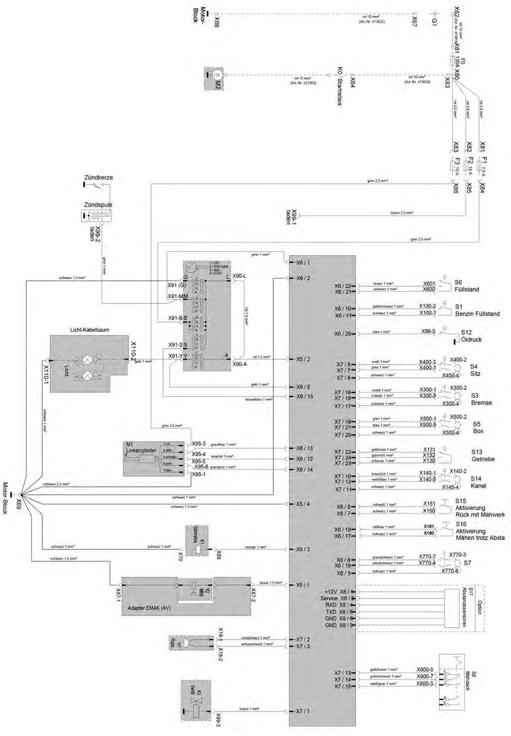
43 43
44 5.2 Lawn tractor with rear discharge without electronic system Workshop manual 44
45 45


 Using two fork spanners, release the locknuts at the rear frame attachment.")
46 6 Adjustment work 6.1 Mowing implement adjustment Park the lawn tractor on a level surface. Set the mowing implement to its lowest position. B A = mowing implement adjustment front B = mowing implement adjustment rear See following steps A = mowing implement adjustment front (left and right) Using two fork spanners, release the locknuts at the front frame attachment. Adjust the locknuts equally until the distance of the front mowing implement at the right and the left is 30 mm at each side. Tighten the locknuts. B = mowing implement adjustment rear (left and right) Using two fork spanners, release the locknuts at the rear frame attachment. Adjust the locknuts equally until the distance of the rear mowing implement at the right and the left is 40 mm at each side. Tighten the locknuts. Check the front mowing implement adjustment, if necessary. 46
 and adjust the supporting rim of the box cover positively to the seat console (e).")

47 6.2 Grass catcher Release the screws (a + c) to adjust the box holding arms if the gap between box cover (d) and seat console (e) is not correct. Release the screws (c) and adjust the supporting rim of the box cover positively to the seat console (e). Release the screws (a) and adjust the distance between the seat console (e) and the first edge of the box cover (d) to 19 mm. 6.3 Brake adjustment The brake of a tractor with transmission can be adjusted. The brake linkage is in the vehicle frame in driving direction right. Merely the discharge channel need to be removed for adjustment. Screw the self-locking nut (a) onto the brake linkage until it is in contact with the spring. 47

.")
48 6.4 Propulsion pedals The distance between the forward accelerator pedal (a) and the step plate (c) should be 35 mm ± 1 when the pedal is not pressed. Adjusting the accelerator pedal (125) Release the nuts (d) on the pedal linkage and adjust the distance of the forward pedal (a). Adjusting the accelerator pedal (95-105) Release the nuts (d) and move the pedal linkage (e). Tighten the nut (d). 48
 from the ball head (c). Loosen the locknut (17 mm) (d). Hold the ball head (c) with pliers.")
 of the steering sector guide.")
49 6.5 Fine adjustment of the steering For the fine adjustment of the steering wheel perform the following setting at the thrust rod (a) front left. Remove the locking bracket (c) from the ball head (c). Loosen the locknut (17 mm) (d). Hold the ball head (c) with pliers. Lift the thrust rod (a) of the ball head (c). Rotate the ball head (c) one revolution anticlockwise or clockwise. 6.6 Steering sector adjustment Slightly release the hexagon head screw (a) of the steering sector guide. While you are pushing the steering sector towards the steering pinion (b), tighten the hexagon head screw (a). Tightening torque: 65 Nm 49
50 7 Torque setting Object Engine Tightening torque Nm (± 2 Nm) Comment Tighten petrol engine (4x) 25 Oil drain plug Blade brake clutch 70 Screw lock with Loctite Transmission 25 Steering First, tighten the transmission screws, then the screws at the bracing. Grease bearing bush. Steering sector guide 25 Grease the steering sector specifically only at the bearing surfaces and the teeth. Steering sector pivot 65 Steering wheel fastening screw 20 Ball head M10 x 1 50 Steering-axle stub clamping lever 20 Mowing implement Blade 65 Tensioning pulley on rocker 25 Distance blade to lower housing edge 7... max. 12 mm. Blade offset max. 3 mm Grease the bearing bush of the tensioning pulley rocker. The rocker must be able to move smoothly. Mowing implement V-belt pulley 65 Guide pulleys 45 Mowing implement bearing block 25 Mowing implement suspension rocker Mowing implement adjustment front M12 Propulsion Tensioning pulley on the frame
51 51
52 Emak S.p.A Bagnolo in Piano (RE) Italy Tel Fax
TUFF TORQ TRANSAXLE. Tuff Torq Hydrostatic Transaxle. Transaxle Removal Tuff Torq
 Tuff Torq Hydrostatic Transaxle Internal Service 3. Disconnect the cotter pin and the washer to the brake rod (Figure 63). Internal service information is contained in the Tuff Torq KGIA Transaxle Service
Engine Removal/Installation
 Engine Removal/Installation Make sure jacks and safety stands are placed properly and hoist brackets are attached to correct positions on the engine. (See Section 1). Apply parking brake and block rear
Repair Manual 11/99 PS-34. Page 1
 Repair Manual /99 PS-4 Page Table of contents Index Technical Data page Special tools 4 Repair instructions, general 0 Chain brake 6 0 Centrifugal clutch 8 0 Oil pump 9-04 Ignition system - 0 Starting
ProLine. 44 Mower. for 120 Traction Unit. Model No & Up. Operator s Manual
 FORM NO. 9 ProLine Mower for 0 Traction Unit Model No. 05 99000 & Up Operator s Manual IMPORTANT: Read this manual carefully. It contains information about your safety and the safety of others. Also become
GROUNDSMASTER. 52 Recycler. for 120 Traction Unit. Model No & UP. Operator s Manual
 FORM NO. 8-980 Rev A GROUNDSMASTER 5 Recycler for 0 Traction Unit Model No. 077 79000 & UP Operator s Manual IMPORTANT: Read this manual carefully. It contains information about your safety and the safety
Printed from CyberCat-STIGA Section: ESTATE PRESIDENT ESTATE TORNADO HST BRAKE CONTROL DRIVE CONTROL
 Section: ESTATE PRESIDENT ESTATE TORNADO HST BRAKE CONTROL DRIVE CONTROL Section: ESTATE PRESIDENT ESTATE TORNADO HST BRAKE CONTROL DRIVE CON 2522 2532 1 1 1136-0510-01 Pedal 2 1 1136-0151-01 Pedal cover
3 Axles and brakes. 3.1 Function and construction of the axles Construction Function
 3 Axles and brakes 3.1 Function and construction of the axles 3.1.1 Function Each wheel has an independent suspension system in the axle body (1), so that individual wheel suspension is provided. The swinging
Transmission MV702. Product Installation & Troubleshooting
 Transmission MV702 Product Installation & Troubleshooting 39036A 2018 I Remove transmission Product installation MV702 1) Remove mower wheels, plastic covers and axle gears from both sides 2) Remove belt
Maintenance Information
 Form 16575334 Edition 1 April 2005 Electric Screwdrivers EL, EP and ET 34V DC Series Maintenance Information Save These Instructions WARNING Maintenance procedures have the potential for severe shock hazard
ProLine. 36 Mower. for Mid-Size Traction Unit. Model No & Up. Operator s Manual
 FORM NO. 8 77 Rev A ProLine 6 Mower for Mid-Size Traction Unit Model No. 05 79000 & Up Operator s Manual IMPORTANT: Read this manual carefully. It contains information about your safety and the safety
Chassis. Body. Steering. Transmission. Cutting Plate Lifting. Cutting Plate. Guards. Engine - GGP. Electrical Parts. Labels. Optionals On Request
 STIGA SD 9813-7500 432cc EMC Documents Chassis Body Steering Brake And Gearbox Controls Technical information Article number 2T0520424/10 Item Status Available Season 2009-2010 Battery charger Yes Blade
Hexhead Torque Values
 Contents: 11: Engine 12: Engine Electrical 13: Fuel Preparation 16: Fuel Supply 17: Cooling 18: Exhaust 21: Clutch 23: Gearbox 31: Front Axle, Front Wheel Steering 32: Steering 33: Rear axle, rear-wheel
STIGA TORNADO 51 S 51 SE PRO 51 S
 STIGA TORNADO 51 S 51 SE PRO 51 S 8211-0225-09 SVENSKA S 1 2 3 1. 2. ADD FULL FULL ADD ADD FULL 0,15 l. 3. LS 45 4. XTE 60 3x 5. LS 45 6. XTE 60 STOP I H 7. 8. 2 S SVENSKA 9. 10. 11. 12. LS 45 0,75 mm
Wheel Horse. 36 Tiller. Model No & Up. Operator s Manual
 FORM NO. 8 9 Rev. A Wheel Horse 6 Tiller for Classic Garden Tractors Model No. 7970 690000 & Up Operator s Manual IMPORTANT: Read this manual carefully. It contains information about your safety and the
Parts Catalogue BT 98 HC. 2T /A11 - Season 2015
 Parts Catalogue BT 98 HC 2T0620424/A11 - Season 2015 Use GLOBAL GARDEN PRODUCT Genuine Spare Parts specified in the parts list for repair and/or replacement. The contents described in the parts list may
Wheel Horse. 44 Snowthrower. for 5xi Lawn and Garden Tractors. Model No & Up. Operator s Manual
 FORM NO. 8 Rev A Wheel Horse Snowthrower for 5xi Lawn and Garden Tractors Model No. 7966 890050 & Up Operator s Manual IMPORTANT: Read this manual, and your tractor manual, carefully. They contain information
BRAKE E
 8-1 GENERAL...8-2 SPECIFICATIONS...8-6 COMPONENTS...8-7 FRONT BRAKE...8-12 DISASSEMBLY INSPECTION REASSEMBLY (Pn1, Cu2 3 TON SERIES)...8-12 DISASSEMBLY INSPECTION REASSEMBLY (Pn2 3 TON SERIES)...8-17 BRAKE
Z Master. 62 Mower. for Z Master Z 255 Traction Unit. Model No & UP. Operator s Manual
 FORM NO. 9 88 Z Master 6 Mower for Z Master Z 55 Traction Unit Model No. 7408 89000 & UP Operator s Manual IMPORTANT: Read this manual carefully. It contains information about your safety and the safety
Online version - not for reprint
 4. CLUTCH, CHAIN DRIVE, CHAIN BRAKE, CHAIN TENSIONER 4. Clutch Drum/Chain Sprocket 43RA007 VA 70RA005 VA - Remove the chain sprocket cover. Disengage the chain brake by pulling the hand guard toward the
 > BT 102 HCB 51 48 13 5 12 9 8 10 11 40 37 41 38 43 45 49 46 47 34 39 50 34 60 61 42 17 44 36 35 52 19 18 16 15 54 14 31 105 7 6 4 32 84 31 53 55 57 103 33 83 58 59 55 56 104 95 94 102 Frame POS CODE Q.TY
1. SPECIFICATION Typ. HPS EPS Capacity 120 A 140 A. 76/140 A at 1,800/6,500 rpm. 70/120 A at 1,800/6,500 rpm. Normal output.
 145300 093 1. SPECIFICATION Typ. HPS EPS Capacity 120 A 140 A Alternator Battery Normal output 70/120 A at 1,800/6,500 rpm 76/140 A at 1,800/6,500 rpm Regulator voltage 14.6 V Brush Length 12.5 mm Wear
Wheel Horse. 42 Mower. for Lawn and Garden Tractors. Model No & Up. Operator s Manual
 FORM NO. 9 559 Rev A Wheel Horse 4 Mower for Lawn and Garden Tractors Model No. 78 890000 & Up Operator s Manual IMPORTANT: Read this manual carefully. It contains information about your safety and the
36 Rear Discharge Mower
 FORM NO. 8 95 Rev. A Wheel Horse 6 Rear Discharge Mower for Classic Garden Tractor Model No. 7805 790000 & Up Operator s Manual IMPORTANT: Read this manual carefully. It contains information about your
Printed from CyberCat-STIGA Section: GARDEN ELECTRICAL SYSTEM
 Section: GARDEN ELECTRICAL SYSTEM Section: GARDEN ELECTRICAL SYSTEM 2312 2333 1 1 1134-3625-01 Harness 2 1 1134-3623-02.Interlock module 4 2 9849-8013-16 Screw 5 2 1134-3132-01 Cable holder 6 2 1134-3204-01
WARNING: ALWAYS relieve fuel pressure before disconnecting any fuel related component. DO NOT allow fuel to contact engine or electrical components.
 4.0L V8 - VINS [K,U] Selected Block 1990 Lexus LS 400 For Lextreme Powertrain 2020 S. Hacienda Blvd. # D Hacienda Heights California 91745 Copyright 1998 Mitchell Repair Information Company, LLC Friday,
Illustrated Parts List
 Illustrated Parts List Hydrostatic Lawn Tractor IMPORTANT: Read safety rules and instructions carefully before operating equipment. Warning: This unit is equipped with an internal combustion engine and
14A6816H190 GT-2150 (2003) Page 1 of 28 Carburetor
 Page 1 of 28 Carburetor") 14A6816H190 GT-2150 (2003) Page 1 of 28 Carburetor 14A6816H190 GT-2150 (2003) Page 2 of 28 Carburetor TC-640221 1 /P Carburetor (Incl 184 of Engine Parts Lists) 1 TC-640216 1 Throttle Shaft & Lever Assembly
14A6816H190 GT-2150 (2003) Page 1 of 28 Carburetor 14A6816H190 GT-2150 (2003) Page 2 of 28 Carburetor TC-640221 1 /P Carburetor (Incl 184 of Engine Parts Lists) 1 TC-640216 1 Throttle Shaft & Lever Assembly
OWNER S MANUAL RIDE-ON LAWNMOWER. SUPPLEMENT FOR M SERIES. Part N o :
 RIDE-ON LAWNMOWER OWNER S MANUAL www.masport.com SUPPLEMENT FOR M SERIES IMPORTANT: Keep these instructions and the engine booklet in a safe place for future reference. They contain important information
WAP disc brake technology. Assembly, operating and maintenance instructions
 WAP disc brake technology Assembly, operating and maintenance instructions Number MA-025 Date 22.07.2010 1 Please read this operating and service manual before starting the vehicle. It forms part of the
Wheel Horse. 52 Mowers. Model No & Up Model No & Up. Operator s Manual
 FORM NO. 9-567 Wheel Horse 5 Mowers for Lawn & Garden Tractors Model No. 7880 890000 & Up Model No. 7885 890000 & Up Operator s Manual IMPORTANT: Read this manual carefully. It contains information about
Removing/installing final drive
 1(16) Removing/installing final drive Special tools: 998 5972, 999 5561, 999 5652, 999 5659, 999 5660 Removing Note! Position the rear lifting arms on the arrows on the sills. This is so the support arm
Wheel Horse. 48 Mower. for 5xi Tractors. Model No & Up. Operator s Manual
 FORM NO. 9 Wheel Horse 48 Mower for 5xi Tractors Model No. 786 990000 & Up Operator s Manual IMPORTANT: Read this manual, and your tractor manual, carefully. They contain information about your safety
Quiet Collector. Model No & Up
 FORM NO. -8GB Rev A Quiet Collector Model No. 795-890000 & Up Operator s Manual IMPORTANT: Read this manual, and your tractor manual, carefully. They contain information about your safety and the safety
ELECTRIC CLUTCH HYDRO DRIVE RMO TRACTORS LT-200 SERIES
 Parts Manual for ELECTRIC CLUTCH HYDRO DRIVE RMO TRACTORS LT-200 SERIES MODEL ELT18538 (2690497) ELT2044 (2690498) LT18538 (2690440) LT18500 (2690518) LT2042 (2690441) LT2044 (2690442) LT22500 (2690443)
RO Automatic trailer coupling. Repair instructions. 5KPVM02000 Towing Hitch Automatic Rockinger RO244A
 utomatic trailer coupling Repair instructions 5KPVM02000 Towing Hitch utomatic Rockinger RO244 5KPVM02010 Towing Hitch utomatic Rockinger foot operated RO244L Contents 1 General Validity and application
Parts Catalog. Commercial / Residential 33 Mower
 Parts Catalog R Commercial / Residential 33 Mower Worldlawn Power Equipment, Inc. 422 Turnbull Canyon Road City of Industry CA 91744 Toll Free Number:1-866-9-Mowers(1-866-966-9377) CONTENT CONTENT Mower
Gearbox sectional drawing
 Gearbox sectional drawing BMW Grafik Design MT- KL39000 3.5 3.6 3 4 77 3 4 77 3473 3 4 7 3 4 7 3 4 73 KL300 Replacing the shaft sealing rings in the gearbox housing and gearbox cover All shaft sealing
Side Discharge Chute Oil Filler & Dipstick Silencer/Exhaust
 1 SPECIFICATION Electric Start Engine - Size 6HP Engine speed 2850rpm Metal Deck Cutting width 550mm (22 ) Adjustable cutting height 7 Grass collection capacity 60L Gross weight 41Kg Fuel type Unleaded
Form No Wheel Horse. 52 in. Mower 5xi Tractor Attachment. Model No and Up. Operator s Manual. Domestic English (EN)
") Form No. -50 Wheel Horse 5 in. Mower 5xi Tractor Attachment Model No. 7870 0000000 and Up Operator s Manual Domestic English (EN) Contents Page Introduction................................ Safety and Instruction
Form No. -50 Wheel Horse 5 in. Mower 5xi Tractor Attachment Model No. 7870 0000000 and Up Operator s Manual Domestic English (EN) Contents Page Introduction................................ Safety and Instruction
48 Side Discharge Mower
 FORM NO. 9 7GB Wheel Horse 48 Side Discharge Mower for Lawn & Garden Tractors Model No. 7868 790000 & Up Operator s Manual IMPORTANT: Read this manual carefully. It contains information about your safety
Parts Catalogue BT 66. 2T /14 - Season 2015
 Parts Catalogue BT 66 2T0045404/14 - Season 2015 Use GLOBAL GARDEN PRODUCT Genuine Spare Parts specified in the parts list for repair and/or replacement. The contents described in the parts list may change
Wheel Horse. 48 Mower. for Lawn and Garden Tractors. Model No & Up. Operator s Manual
 FORM NO. 5 Wheel Horse 48 Mower for Lawn and Garden Tractors Model No. 786 990000 & Up Operator s Manual IMPORTANT: Read this manual carefully. It contains information about your safety and the safety
LAWN MOWER OWNER S MANUAL
 LAWN MOWER OWNER S MANUAL Woodies SKU: 1153279 & 1153280 CAUTION: Read and follow all Safety Rules and Instructions before operating this equipment Thank you for choosing our Gasoline Lawnmower. 1 To ensure
Parts Catalog Apex 47 Series Model Battery
 Parts Catalog Table of Contents Side brush R.H. (97085690)... 4 Front wheel drive (97077317)... 8 Accelerator B (97077374)... 12 Steering (til 6502.40.5.0171.3) (97077127-1a 6502-40)... 16 Steering (from
SECTION steering mechanism
 07-302.01/ 1 2011MR17 SECTION 07-302.01 GENERAL Description See Figure 1. The includes the steering wheel (1), the steering column, the miter box (3), the steering shafts (2 and 4), and the drag link (7).
NILFISK BA 500 Service Manual
 NILFISK BA 500 Service Manual Model 66324400 12/94 Form Number 043023 TABLE OF CONTENTS Batteries...21 Brush Drive Belt Adjustment Or Replacement...7 Brush Drive Motor - Carbon brush Inspection... 8 Brush
30500x92A Lawn Tractor (1998) Page 1 of 13 Body Chassis
 Page 1 of 13 Body Chassis") 30500x92A Lawn Tractor (1998) Page 1 of 13 Body Chassis 30500x92A Lawn Tractor (1998) Page 2 of 13 Body Chassis 1 092387 Seat 2 056516E700 Hinge, Seat 3 028X64 Retainer 4 018X16 Lockwasher 5 001X45 Bolt,
30500x92A Lawn Tractor (1998) Page 1 of 13 Body Chassis 30500x92A Lawn Tractor (1998) Page 2 of 13 Body Chassis 1 092387 Seat 2 056516E700 Hinge, Seat 3 028X64 Retainer 4 018X16 Lockwasher 5 001X45 Bolt,
Finishing Mower Estate 72
 Finishing Mower Estate 72 Owners/Operators Manual & Spare Parts List Issue Date: October 2011 1 Introduction Your FIELDMASTER Estate 72 Finishing Mower has been designed to do a range of work to your satisfaction.
Engine Does Not Start or Is Hard to Start Cause of Trouble. 1. Open the drain screw, and check Fuel not supplied (1) Fuel tank empty
 Fuel tank empty") 20. Engine Does Not Start or Is Hard to Start 20-1 Engine Output Insufficient 20-2 Poor Performance at Low Speed and Idling 20-3 Poor Performance at High Speed 20-3 Unsatisfactory Operation 20-4 Fuel Gauge
20. Engine Does Not Start or Is Hard to Start 20-1 Engine Output Insufficient 20-2 Poor Performance at Low Speed and Idling 20-3 Poor Performance at High Speed 20-3 Unsatisfactory Operation 20-4 Fuel Gauge
1. SPECIFICATION
 000000 093 1. SPECIFICATION Specification HPS EPS Alternator Crankshaft pulley : Alternator Pulley 1 : 2.94 Normal output (idling/2200 rpm) 70/120 A 70/140A Regulator voltage 14.6 V Brush Length 12.5 mm
BRAKE SYSTEM Return To Main Table of Contents
 BRAKE SYSTEM Return To Main Table of Contents GENERAL... 2 BRAKE PEDAL... 10 MASTER CYLINDER... 13 BRAKE BOOSTER... 16 BRAKE LINE... 18 PROPORTIONING VALVE... 19 FRONT DISC BRAKE... 20 REAR DRUM BRAKE...
Original Operating Manual
 matev GmbH Nürnberger Str. 50 90579 Langenzenn T +49 (0) 9101 9087-0 F +49 (0) 9101 9087-20 info@matev.eu www.matev.eu Original Operating Manual Snow blade SRM-FB 120 CD Angle adjustment mechanical Version
SERVICE I IPL, CTH 180, , CTH 180. Spare parts Ersatzteile Pièces détachées Reserve onderdelen Repuestos Reservdelar
 SERVICE 7 I9900007 IPL, CTH 180, 1999-01, 106 25 67-61 CTH 180 Spare parts Ersatzteile Pièces détachées Reserve onderdelen Repuestos Reservdelar CTH 180 Engine Assembly 18 HP VANGUARD CTH 180 Engine Assembly
Light Shipping Location. Remove nut to detach headlight from under dash. Keep nut to mount light on unit. Figure 5
 Install Headlight (900, 0, 05) (Figure 5). Remove headlight from location under dash panel. Keep nut for installation.. Attach headlight to bolt on right side of the dash. Fasten with nut removed in step..
Genuine Spare Parts SC 9013 H SC 92 H SC 9216 H. Copyright 2012 Global Garden Products
 Genuine Spare Parts SC 9013 H SC 92 H SC 9216 H Copyright 2012 Global Garden Products 51 48 13 5 12 9 8 10 11 40 37 41 38 43 45 49 46 47 34 39 50 34 60 61 42 17 44 36 35 52 19 18 16 15 54 14 31 7 4 32
48 Side Discharge Mower
 FORM NO. 9 650 Rev A Wheel Horse 8 Side Discharge Mower for Classic Garden Tractor Model No. 786 890000 & Up Operator s Manual IMPORTANT: Read this manual carefully. It contains information about your
1989 Jeep Cherokee. STEERING COLUMN' '1989 STEERING Jeep Steering Columns STEERING COLUMN STEERING Jeep Steering Columns
 STEERING COLUMN 1989 STEERING Jeep Steering Columns DESCRIPTION All models use collapsible steering columns. All columns have integral ignition switch and locking device. Optional tilt wheel is available
Original Operating Manual
 matev GmbH Nürnberger Str. 50 90579 Langenzenn T +49 (0) 9101 9087-0 F +49 (0) 9101 9087-20 info@matev.eu www.matev.eu Original Operating Manual Front Power System und Front PTO shaft FPS- JD X 950 R for
STIGA PARK 4 WD 107 M 107 M HD 121 M. 125 Combi Pro B INSTRUCTIONS FOR USE. »HC P K»fl œoà «Œ EÀfl
 STIGA PARK 4 WD 107 M 107 M HD 121 M 125 Combi Pro B INSTRUCTIONS FOR USE»HC P K»fl œoà «Œ EÀfl 8211-0543-01 1 125 Combi Pro 2 125 Combi Pro 3 125 Combi Pro 121 M 107 M HD A B C B 4 125 Combi Pro 107 M
MODEL x692A REPAIR PARTS HOOD & GRILL
 MODEL 0xA HOOD & GRILL 0 0 0 0 0 0 0 0 MODEL 0xA Screw x0 Dash 00 Trim. 00 Cable Hood Assemnly 00E00 Screw x Lens & Reflector Assembly Cap, Pivot 0 Bolt, Shoulder x 0 Base, Pivot 0 Brace, Right Grille
Service Manual. LT-5 Lawn Tractor
 Service Manual LT-5 Lawn Tractor NOTE: These materials are for use by trained technicians who are experienced in the service and repair of outdoor power equipment of the kind described in this publication,
Rider 850, Rider 970, Rider 850 HST, Rider 970 HST, Rider 1030 Bioclip, Rider Workshop Manual.
 For Husqvarna Parts Call 606-678-96 or 606-56-98 Rider 850, Rider 970, Rider 850 HST, Rider 970 HST, Rider 00 Bioclip, Rider 00 Workshop Manual 0 89-6 For Husqvarna Parts Call 606-678-96 or 606-56-98 Workshop
INSTRUCTION MANUAL. LAWN MOWER LazerMulch LMS400 CONSUMER HELPLINE PLEASE READ THE INSTRUCTIONS IN THIS MANUAL BEFORE OPERATION.
 INSTRUCTION MANUAL LAWN MOWER LazerMulch LMS400 CONSUMER HELPLINE 1800 466 068 PLEASE READ THE INSTRUCTIONS IN THIS MANUAL BEFORE OPERATION. INSTRUCTION MANUAL LMS400 LAWN MOWER What you get with your
Volkswagen Phaeton 43-2
 Стр. 1 из 27 Volkswagen Phaeton 43-2 Self-leveling suspension, servicing Troubleshooting of air spring struts and level control system Condition Verification Possible causes Corrective action Very slow
Installation Manual TWM Performance Short Shifter Cobalt SS/SC, SS/TC, HHR SS, Ion Redline and Saab 9-3
 Page 1 Installation Manual TWM Performance Short Shifter Cobalt SS/SC, SS/TC, HHR SS, Ion Redline and Saab 9-3 Please Note: It is preferable to park on a flat surface, as you will have to engage and disengage
Agri-Fab OWNERS MANUAL. Model No " ROUGH CUT TRAILMOWER. CAUTION: Read Rules for Safe Operation and Instructions Carefully
 Agri-Fab OWNERS MANUAL Model No. 45-0362 CAUTION: Read Rules for Safe Operation and Instructions Carefully Safety Assembly Operation Maintenance Parts 42" ROUGH CUT TRAILMOWER NOTE: Your mower deck will
SP6. Automatic Battery Charger. Model
 Model SP6 Automatic Battery Charger OWNERS MANUAL PLEASE SAVE THIS OWNERS MANUAL AND READ BEFORE EACH USE. This manual will explain how to use the charger safely and effectively. Please read and follow
Your G3 buggy is fitted with three switches on the front part of the body:
 CONTENTS Buggy operation... 3 General Maintenance... 5 Technical Maintenance... 6 Front wheel bearing replacement... 6 Rear wheel bearing replacement... 7 Chain replacement... 8 Chain Adjustment... 9 Brake
D50-LN BONNET ASSEMBLY
 1 16 9 1 16 1 16 31 D50-LN BONNET ASSEMBLY 20 32 15a 19 29 10 15 30 13 12 7 16 28 29 11 13 1 4 2 2 3 23 14 8 5 7 21 23 6 4 7 16 2 1 2 2 1 1 16 1 2 1 16 16 7 7 16 1 1 16 1 18 23 7 16 17 27 23 24 27 25 16
Quiet Collector. Model No & Up
 FORM NO. -0 Quiet Collector Model No. 79-990000 & Up Operator s Manual IMPORTANT: Read this manual, and your tractor manual, carefully. They contain information about your safety and the safety of others.
ELECTRIC CLUTCH HYDRO DRIVE RMO TRACTORS LT-200 SERIES
 Parts Manual for ELECTRIC CLUTCH HYDRO DRIVE RMO TRACTORS LT-200 SERIES MODEL ELT18538 (2690497) ELT18538 (2690796) ELT18540 (2690781) ELT2044 (2690498) LT18538 (2690440) LT18500 (2690518) LT2042 (2690441)
SERVICE MANUAL. Chairman
 SERVICE MANUAL Chairman US How to contact Permobil Permobil Inc. USA 6961 Eastgate Blvd. Lebanon, TN 37090 USA Phone: 800-736-0925 Fax: 800-231-3256 Email: info@permobilusa.com Head Office of the Permobil
The steering column is of a modular construction and features easy to service electrical switches.
 file://c:\tso\tsocache\vdtom_5368\svk~us~en~file=svkb4a01.htm~gen~ref.htm Page 1 of 3 Section 11-04A: Steering Column, Ranger DESCRIPTION AND OPERATION 1997 Ranger Workshop Manual Steering Column NOTE:
KENT/Euroclean MODELS: (2)
") Razor 17B - 20B - 20BT SERVICE MANUAL KENT/Euroclean MODELS: 908 7010 020-908 7011 020-908 7025 020 08603953(2)2003-09 INDEX GENERAL INFORMATION 3 MACHINE LIFTING 3 MACHINE TRANSPORTATION 3 OTHER AVAILABLE
Razor 17B - 20B - 20BT SERVICE MANUAL KENT/Euroclean MODELS: 908 7010 020-908 7011 020-908 7025 020 08603953(2)2003-09 INDEX GENERAL INFORMATION 3 MACHINE LIFTING 3 MACHINE TRANSPORTATION 3 OTHER AVAILABLE
XL HYDROSTATIC TRANSAXLES
 Purging Procedures Due the effects air has on efficiency in hydrostatic drive applications, it is critical that it be purged from the system. These purge procedures should be implemented any time a hydrostatic
STIGA TORNADO 3098 H (2018) 2T /14. Spare parts list Reservdelar Repuestos Ersatzteile Pièces détachées Reserve onderdelen Catalogo ricambi
 2T /14. Spare parts list Reservdelar Repuestos Ersatzteile Pièces détachées Reserve onderdelen Catalogo ricambi") STIGA 2T0630281/14 Spare parts list Reservdelar Repuestos Ersatzteile Pièces détachées Reserve onderdelen Catalogo ricambi Use ST. S.p.A. Genuine Spare Parts specified in the parts list for repair and/or
STIGA 2T0630281/14 Spare parts list Reservdelar Repuestos Ersatzteile Pièces détachées Reserve onderdelen Catalogo ricambi Use ST. S.p.A. Genuine Spare Parts specified in the parts list for repair and/or
* * * * 8 Maintenance Plan 10.1,10.2, ,4 7.1/7.2/7.3
 Maintenance 8 Maintenance Plan * * * * * GB 10.1,10.2,10.3 6.1 12.2 12.1 11.2 12.1 7,4 7.1/7.2/7.3 1.1/1.2/1.3 3.1/3.2/3.3/3.4/4.1/11.1 5.1 5.2 4.2 5.1 5.2 2.1/2.2/2.3/2.4/2.5/2.6/4.1 Item Designation
I Illustrated Parts List LRH B. Ride Mower
 Illustrated Parts List -0 I000 LRH Ride Mower 00B SCHEMATIC TRACTOR-MODEL NO. LRH (00B) RED BLACK BATTERY RED FUSE 0 AMP. RED M STARTER BLACK WHITE SOLENOID B G S M L CLUTCH / BRAKE (PEDAL UP) WHITE IGNITION
1983 BMW 320i. 1.8L 4-CYL 1983 Engines - 1.8L 4-Cylinder Engines - 1.8L 4-Cylinder
 ENGINE IDENTIFICATION 1.8L 4-CYL 1983 Engines - 1.8L 4-Cylinder For engine repair procedures not covered in this article, see ENGINE OVERHAUL PROCEDURES - GENERAL INFORMATION article in the GENERAL INFORMATION
Engine, disassembling and
 Page 1 of 38 13-1 Engine, disassembling and assembling Lock carrier, moving into service position Special tools and equipment 3369 support tool 1 - Bolts 2 - Bolts 3 - Bolts 4 - Bolts 5 - Bore 45 Nm (33
22-1 GROUP 22 MANUAL TRANSAXLE CONTENTS MANUAL TRANSAXLE... 22A MANUAL TRANSAXLE OVERHAUL... 22B
 22-1 GROUP 22 MANUAL TRANSAXLE CONTENTS............................... 22A OVERHAUL..................... 22B 22A-2 GROUP 22A MANUAL TRANSAXLE CONTENTS GENERAL DESCRIPTION......... 22A-3 DIAGNOSIS 22A-6
SERVICE MANUAL. Chairman HD3
 SERVICE MANUAL Chairman HD3 US How to contact Permobil Head Office of the Permobil group Produced and published by Permobil AB, Sweden Edition no.3, 2009-08 Article no.: 201161-US-0 Contents Contents
Valve gear, servicing
 Page 1 of 62 15-1 Valve gear, servicing WARNING! Do not re-use any fasteners that are worn or deformed in normal use. Some fasteners are designed to be used only once, and are unreliable and may fail if
SERVICE MANUAL (2)
") Terra 128B - 132B SERVICE MANUAL 146 0721 000(2)2003-04 INDEX GENERAL INFORMATION 3 MACHINE LIFTING 3 MACHINE TRANSPORTATION 3 OTHER AVAILABLE MANUALS 3 SAFETY - ACCIDENT PREVENTION 4 GENERAL SAFETY RULES
Terra 128B - 132B SERVICE MANUAL 146 0721 000(2)2003-04 INDEX GENERAL INFORMATION 3 MACHINE LIFTING 3 MACHINE TRANSPORTATION 3 OTHER AVAILABLE MANUALS 3 SAFETY - ACCIDENT PREVENTION 4 GENERAL SAFETY RULES
521613x89A Garden Tractor (2001) Page 1 of 24 Blade Drive
 Page 1 of 24 Blade Drive") 521613x89A Garden Tractor (2001) Page 1 of 24 Blade Drive 521613x89A Garden Tractor (2001) Page 2 of 24 Blade Drive Ref # Part Number Qty Description 1 094607E701 Cover, Right Pulley 2 26X250 Screw 3 015X84
521613x89A Garden Tractor (2001) Page 1 of 24 Blade Drive 521613x89A Garden Tractor (2001) Page 2 of 24 Blade Drive Ref # Part Number Qty Description 1 094607E701 Cover, Right Pulley 2 26X250 Screw 3 015X84
ASSEMBLY INSTRUCTIONS FOR CHARGER AND THE BOSS QUICK ATTACH GRASS BAGGER
 ASSEMBLY INSTRUCTIONS FOR CHARGER AND THE BOSS QUICK ATTACH GRASS BAGGER \ \ \ \ ~\ P P-12102 (7/2005) TABLE OF CONTENTS SECTION PAGE WARNING 1 BLOWER PULLEY INSTALLATION 2 ENGINE GUARD REMOVAL BOSS 3
Troubleshooting the Transmission Hydraulic System
 Testing and Adjusting IT28F INTEGRATED TOOLCARRIER POWER TRAIN Testing And Adjusting Introduction Reference: For Specifications with illustrations, refer to SENR5974, IT28F Integrated Toolcarrier Power
Chapter 7 Steering Specifications 7-2 Component Location 7-3 Tests and Adjustments 7-4 Repair Rev B 7-1
 Chapter Steering Specifications................................................................. - Component Location........................................................... - Tests and Adjustments.........................................................
MANUAL TRANSAXLE Return to Main Table of Contents
 MANUAL TRANSAXLE Return to Main Table of Contents GENERAL... 2 MANUAL TRANSAXLE CONTROL... 12 SHIFT LEVER ASSEMBLY... 14 MANUAL TRANSAXLE... 15 MANUAL TRANSAXLE ASSEMBLY... 17 FIFTH SPEED SYNCHRONIZER
M. E. Y. EQUIPMENT MOWER MANUAL
 M. E. Y. EQUIPMENT MOWER MANUAL 200 COLLIER ROAD, BAYSWATER. WESTERN AUSTRALIA 6053 TELEPHONE (08) 9370 1110, FACSIMILE (08) 9370 2566 Web Site: www.mey.com.au Email: info@mey.com.au INTRODUCTION The technical
Service Manual. Bolens 683 Series Box Frame Tractor IMPORTANT: READ SAFETY RULES AND INSTRUCTIONS CAREFULLY
 Service Manual Bolens 683 Series Box Frame Tractor IMPORTANT: READ SAFETY RULES AND INSTRUCTIONS CAREFULLY This Service Manual is not a substitute for the Operator s Manual. You must read, understand and
Models: SP3, SPSS3 Automatic Battery Charger
 OWNERS MANUAL Models: SP3, SPSS3 Automatic Battery Charger PLEASE SAVE THIS OWNERS MANUAL AND READ BEFORE EACH USE. This manual will explain how to use the charger safely and effectively. Please read and
SERVICE MANUAL. Chairman. Playman/Robo
 SERVICE MANUAL Chairman Playman/Robo US How to contact Permobil Permobil Inc. USA 6961 Eastgate Blvd. Lebanon, TN 37090 USA Phone: 800-736-0925 Fax: 800-231-3256 Email: info@permobilusa.com Head Office
465606x692A Lawn Tractor (2001) Page 1 of 25 Drive Assembly
 Page 1 of 25 Drive Assembly") 465606x692A Lawn Tractor (2001) Page 1 of 25 Drive Assembly 465606x692A Lawn Tractor (2001) Page 2 of 25 Drive Assembly 1 26X249 Screw 2 095315 Knob, Parking Brake 3 711691 Nut, Push 4 1001217 Z Rod, Parking
465606x692A Lawn Tractor (2001) Page 1 of 25 Drive Assembly 465606x692A Lawn Tractor (2001) Page 2 of 25 Drive Assembly 1 26X249 Screw 2 095315 Knob, Parking Brake 3 711691 Nut, Push 4 1001217 Z Rod, Parking
Copyright 2014 Global Garden Products 2 STIGA - ESTATE 3084 H
 ESTATE 308 H 35 36 37 3 33 32 38 31 39 0 0 30 28 27 26 25 5 6 11 15 20 22 13 1 1 1 23 12 2 2 3 17 16 18 19 5 2 6 Copyright 201 Global Garden Products 2 STIGA - ESTATE 308 H Chassis POS CODE Q.TY DESCRIPTION
Worldlawn Power Equipment, Inc. Industrial Park 2415 Ashland Ave. Beatrice, NE Toll Free Number:
 Parts Catalog R Commercial / Residential 33 Mower Worldlawn Power Equipment, Inc. Industrial Park 2415 Ashland Ave. Beatrice, NE 68310 Toll Free Number: 1-800-267-4255 Table of Contents Table of Contents
DrVanos.com Stage II Installation Instructions. Tool rental is available with the purchase of a vanos kit *See website for more info*
 DrVanos.com Stage II Installation Instructions Special Tools Needed: Camshaft locking tool TDC Crank pin Sprocket turning tool Tool rental is available with the purchase of a vanos kit *See website for
EXPLODED PARTS LIST VTR 650
 Year: 08 Page(s): / Control Year: 08 Page(s): / No Code Name Qty No Code Name Qty 5356 Brake pedal 9 Washer 5357 Brake assy 50 539 Bolt 3 5358 Gear cap 5 539 Switch base 5359 Spring 5 5393 Micro Switch
Installation Manual. Model T675A Engine Brakes. For Mack 6 Cylinder, 2 valve Head ENDT-673, 675, 676 & E6 Series Engines.
 Engine Brakes Installation Manual Model T675A Engine Brakes For Mack 6 Cylinder, 2 valve Head ENDT-673, 675, 676 & E6 Series Engines TecBrake P.O. Box 27822 Houston, Texas 77227 INSTALLATION MANUAL TECBRAKE
TOYOTA COROLLA 2009 TVIP V4 PREPARATION
 PREPARATION Part #: PT398-02080 Conflicts: NOTE: Part number of this accessory may not be the same as the part number shown. Do not install into Manual Transmission Vehicles or Vehicles without RKE systems.