Volume Supra Digital Control System
|
|
|
- Janel Kennedy
- 5 years ago
- Views:
Transcription

1 Volume 5 Supra Digital Control System PROGRAMMING AND USERS MANUAL
2 P R O G R A M M I N G A N D U S E R S M A N U A L Supra Digital Control System Polar Power Inc Avalon Blvd., Carson, CA Fax: (310) Phone: (310)
3 Table of Contents Safety Notes:... 1 Warnings... 1 Personal Precautions... 1 Scope... 3 Introduction... 3 The Supra Control System Integrates:... 4 Supra Control System Features... 4 The Supra Control System Description... 2 Supra Advantages... 3 Supra Control System Diagram... 5 Supra Control System Overview... 5 Model 250 Controller... 6 Model 290 Engine Interface... 6 Model 320 Display / Keyboard... 7 Model 250 Controller... 8 Voltage Control Range... 8 Output Power Control Range... 8 Input Voltage... 8 Low Power Consumption... 8 Power Required for Engine Speed Control for 8000 Series Alternators... 8 Power Required for the Field Coil for Series 6200 Alternators... 8 Electrical Isolation... 8 Communication between modules... 8 Upgrades... 9 Current Measurement... 9 Operational Environments... 9 Durability / Reliability... 9 Temperature Measurement... 9 Pressure Measurement... 9 Fuel Level Monitor Option... 9 Cooling and Enclosure Purging Kilowatt and Amp Hour Produced Battery Monitor Option Digital Switch Inputs The CAN Bus... 10
4 Engine Speed Model 250 Controller Dimensions Model 290 Engine Interface Operating Voltage Relays Fuses and Switch Currents Analog Input Digital Switch Inputs Model 290 Engine Interface Block Diagram Model 320 Keypad/Display Indicators (LED) Security Model 380 Ethernet Interface Module On board memory Serial Interface VIP Access Enabled Software Management Power Environmental Regulatory Approvals Operating the Supra Controller Operation with the Model 320 Display/Kepad Operation with a Personal Computer Control Sequence Outline Shutdowns and Fault Conditions Stop Sequence Using the Polar Power GUI Software Main Status Screen Windows Common to all Screens Network Status Information Controller Status Information Communications Page General Page Status Page Components Alternator Status Group Box Controller Status Group Box Battery Bank Group Box (optional package) Engine Status Group Box:... 27
5 Switch Status Group Box Switch Status Group Box Engine Control Group Box Alternator Settings Page Over Temp Power Reduction Hour/Minute/Second Group Speed Group Weekly/Monthly Exercise Group Engine Settings Page Speed Control Group Fuel Tank Calibration: Fault Settings group Battery Settings Page A/D Readings Page Factory Page Calibration Group Box: PID / PWM Group Box: Logs Page Communications Page Connection Type Group Box: SMS Messaging Group Box: Version Checking Group Box: Controller Modem Settings Group Box: Switch Custom Text Group Box: Passwords Table of Input/Output Parameters Controller Panel Operation...57 Contact Information...91

6 Safety Notes: Personnel performing operations, procedures, and practices that are included or implied in this manual shall observe the following warnings. Disregard of these warnings and precautionary information can cause serious injury or even DEATH. Warnings Use of this equipment in any manner not specified herein may impair the protection provided by this equipment. Do not use this equipment in any manner not specified by the manufacturer. Maintenance must be performed by qualified personnel. Electrical shock and death can occur from electrical/electronic systems regardless of voltage. Remove all jewelry (rings, watches, bracelets, etc.) from hands and arms before performing any electrical test or maintenance activity. When servicing the generator, engage the emergency stop switch or disconnect all power depending on the service required. The EMERGENCY STOP will lock out automatic, manual, or remote starts which will prevent personal injury. A buzzer will sound at the start sequence to give a warning that the generator is about to start; you must be careful of all rotating parts. Working in the vicinity of a lead acid battery is dangerous. Batteries generate explosive gases during normal operation. Personal Precautions Keep plenty of fresh water and soap nearby in case battery acid contacts skin, clothing or eyes. Wear complete eye protection. Avoid touching eyes while working near batteries. Wash your hands with soap and warm water when done. If battery acid contacts skin or clothing, wash immediately with soap and water. If acid enters an eye, flood the eye with running cool water at once for at least 15 minutes and get medical attention immediately following. Baking soda neutralizes lead acid battery electrolyte. Keep a supply on hand in the area of the batteries. NEVER smoke or allow a spark or flame in vicinity of a battery or generator. 1
7 Be extra cautious to reduce the risk of dropping a metal tool onto batteries. It could short circuit the batteries or other electrical parts that can result in fire or explosion. Remove personal metal items such as rings, bracelets, necklaces, and watches when working with a battery or other electrical current. A battery can produce a short circuit current high enough to weld a ring or the like to metal, causing severe burns NOTE: When servicing the generator, engage the emergency stop switch or disconnect all power depending on the service required. The EMERGENCY STOP will lock out automatic, manual, or remote starts. This will prevent injury. A buzzer will sound at the start sequence to give a warning that the generator is about to start; you must be careful of all rotating parts. 2
8 Scope This manual provides safety guidelines as well as operating and programming information for the Supra Digital Control System. Introduction The Supra Digital Control System is a highly integrated control solution that will improve the reliability, serviceability, and the ability to remotely control a DC Generator based power systems (Genset). The Supra Control System can control power to DC loads and serve as a fuel based programmable battery charging system. 3
9 The Supra Control System Integrates: Engine Control Alternator Voltage Regulation Auxiliary Power Inputs Operator Interface Remote Site Monitoring and Communications The Supra s high level of circuit integration eliminates separate and independent control modules, simplifying the wire harness and eliminating the typical conflicts between modules integrated from different manufactures. It can be remotely controlled, monitored, calibrated, and tested, through an industrial modem, cell phone modem, or Ethernet. Communication is accessible locally with a PC Laptop or remotely through the Internet to facilitate site support and reduce costly visits to the site. The Supra Digital Control System provides a complete log of alarms and operating parameters at the completion of a charge cycle or shutdown due to a fault condition. Alarms can be reset and the generator exercised remotely to help identify potential problems before scheduling a site visit. If an unscheduled maintenance is required, the technician can arrive at the site prepared, reducing the need for a second visit. The Supra Digital Control System facilitates Hybrid Systems incorporating other sources of power including solar, wind, hydro, and utility. All connections to the controllers are through Amp/Tyco Circular C type connectors facilitating onsite repair through controller swapping (plug and play). The controller circuits were designed to meet the most stringent Military and Telecommunications requirements for EMI, EMP, and Ripple. The Supra Controller can meet the requirements of any type of grounding requirement: negative, positive, or float. Supra Control System Features The Supra Digital Control System features include: Integration of engine control, alternator, and external communications into one control system. Precise control of voltage and current. Automatic Warnings - when certain services are required. Automatic Generator Shut Down - if certain preprogrammed faults and-or limits are detected. Accepts a power input ranging from 12 to 65 volts. 4
10 Communications with a remote terminal, via RS 232, CAN bus, Bell 212 industrial modem, Ethernet, or Cell modem communications. Selectable English or Metric units through the control panel or the Graphics User Interface. Operator can remotely change the operating program (software) and reconfigure the set-points and calibrations. Operator can set the Controller to automatically exercise the generator periodically by inputting the run duration and day and hour of the week or month to run. The Controller can call the remote terminal if a failure occurs or send an SMS message depending on the options in place. The system can be remotely recalibrated, reset, and used to perform diagnostic tests, and override the STOP, AUTOMATIC, or MANUAL modes. Normal runs, alarms, and abnormal shut downs are recorded and kept in the memory. If the memory fills up the oldest events are over written. Up to 2047 events can be permanently stored. Operator can view the state and status of the generator, load battery bank, and starting battery using communications port. The Supra Control System Description The Supra Control System integrates the control of the engine, alternator, and external communications into one control system. The Supra Control System consists of the Model 250 Controller and the Model 290 Engine Interface. The Model 250 Controller provides the control, monitoring, and communications. The Model 290 Engine interface houses the relays and fuses required for automatic engine control. For manual/nonautomatic systems the Model 290 is not required. The Supra 250 Controller accepts a power input ranging from 12 to 64 volts. The 250 is typically connected to the load battery and not the starting battery. The Model 290 Engine Interface is available in either of two voltage ranges, 7 to 16 VDC or 16 to 64 VDC. The Model 290 can connect to either the 12 volt starting battery or the load battery (with the 16 to 64 volt option) for the logic power. A connection to the starting battery is required for engine functions such as the glow plug, starter, and fuel relay components. The Model 250 Controller is accessed through the Model 320 Display/Keypad which provides a five push-button control panel and RS-232 or CAN bus ports. The Model 320 Display/Keypad contains a back-lit, dot-matrix liquid crystal display suitable for 20 to 70 C operation. The Supra 250 Controller usually derives it power from the output connections of the genset up to 65 volts. Alternately, on higher voltage models, the controller voltage is supplied by an auxiliary 24 volt source. Voltage monitoring on the higher voltage models is derived through a voltage divider module. In the initial setup the user chooses either English or Metric units through the control panel or the Graphics User Interface. 2
11 The Model 250 Controller has the capability to communicate with a remote terminal, via RS 232, CAN bus, Bell 212 industrial modem, Ethernet, or Cell modem communications. The user will be able to view the state and status of the generator, load battery bank, and starting battery. The operator can remotely change the operating program and reconfigure the set-points and calibrations. The Controller can call the remote terminal if a failure occurs or send an SMS message depending on the options in place. Remotely, through the software GUI, the system can be recalibrated or reset, perform diagnostic tests, and override the STOP, AUTOMATIC, or MANUAL modes. The user can set the Controller to automatically exercise the generator periodically by inputting the run duration and day and hour of the week or month to run. Normal runs, alarms, and abnormal shut downs are recorded and kept in the memory. If the memory fills up the oldest events are over written. Up to 2047 events can be permanently stored. Supra Advantages 1. Optically isolated RS 232 and CAN bus communications allow the generator to be controlled (locally or remotely) through a PC computer with Polar s GUI or the customer s own CAN bus. 2. Precision battery charging using control of both the voltage and current output. Battery charging using a single parameter of voltage control is insufficient because small millivolt changes can cause undesirable, large current fluctuations. 3. User configurable battery charging algorithms for different battery technologies. User configurable: current limit in bulk charge, temperature compensation curves, differentiation of load current and battery charge, and float voltages. 4. Control of Engine: RPM, starter motor, glow plugs, choke, fuel racks, fuel and engine block heaters, and cooling fans. Accurate monitoring of temperatures, pressures, coolant, and fuel levels. 5. Digitally controlled variable parameters: Digital control allows the generators, voltages, currents, engine speeds, and sensor calibrations to be remotely calibrated. All potentiometers were eliminated 6. Set points and recalibration can be performed remotely through the Internet, RS 232, Ethernet, or Cell Phone Modem using Polar s GUI interface. 7. Field upgradeable software bit A/D converters and optically isolated linear amplifiers provide accurate voltage, current, fuel level, oil pressure, temperature, and engine speed measurements. 9. Sensor and communications ports are isolated, so the failure of an input sensor or communications port will not contribute to system conflicts and issues. 3
12 10. High immunity to electrical noise. Sources of noise include the starter motor, spark plugs, lightning, coupling of AC sources, cell phone transmissions, microwave, and radar transmissions. 11. Very low conductance and radiation of EMI: A clean DC Power Source is incorporated for the provisioning of sensors, field coils, and actuators with a resultant effect of a reduced EMI source. This is unlike other controller manufacturers, who typically use an unfiltered PWM source of power. 12. Polar Power s unique circuit provides reliable operation in floating, positive, or negative ground systems. Polar uses switching power supplies to isolate both positive and negative inputs. (Most other controllers use a lower cost 3-pin voltage regulator that creates problems when moving between positive and negative ground systems.) 13. The power supplies input and output signals and is fully isolated for up to 1500 Volts, via opto and galvanic couplers. The Supra Control System can tolerate most Hipot testing with controls connected in place. 14. Superior high voltage and current surge immunity from lightning, alternator surges, and load dumps with active voltage clipping circuits. 15. Supra s microprocessor and relays are able to operate under low voltage conditions during engine cranking with a starting battery in poor condition. 16. AMP/Tyco Circular C type connectors are used to maintain a high degree of reliability and provide ease of field service. Signal pins are gold plated and power pins are silver plated, providing low maintenance operation in high humidity, salt fog, and sandy environments. 17. Model 250 and 290 enclosures are gasket sealed to IP Conformally coated circuit boards: all components are soldered in place, except for fuses in the Model 290 module. 4

13 Supra Control System Diagram Supra Control System Overview 250 Controller 290 Engine Interface 320 Operator Interface Sensors and Cable Harnesses Software 5

14 Model 250 Controller This module is the heart of the system providing the primary logic control, analog and switches inputs, communication, and the generator output regulation. The Model 250 Controller has a 15 amp bipolar power supply controlled by the microprocessor to provide the generator s voltage and current regulation. Regulation is achieved either through controlling the field coil as required by the Model 6200 alternators or through an actuator on the engine for speed control as required by the Model 8000 series. Analog to digital converters read the various engine, alternator, and control sensors for temperature, pressure, voltage, current, and speed. 5 switch inputs to monitor: intrusion, over temperatures, presence of AC grid, solar or wind power, fuel leaks, or other special requirements. The Model 250 Controller communicates with the 290 Engine Interface, the 320 Operator Interface, and accessory modules through a CAN bus interface. CAN bus interface is open to users for transmitting operational data or receiving control commands from the user s CAN bus system. The CAN bus protocol is unique to Polar Power. The Model 250 also has two RS-232 ports. These ports are optically isolated from the system voltage and are used for communicating with the: Model 380 Ethernet module, Cell Phone module, PC type Computer, or other customer devices. The Model 250 facilitates Hybrid systems incorporating other charging sources of power including solar, wind, hydro, and utility. Model 290 Engine Interface This assembly contains the relays and switched contact inputs for the engine control as required for fully automated operation. 6

15 The Model 290 Engine Interface is designed as a separate module to facilitate access to replaceable fuses used to protect the system against catastrophic damage from shorts, over current, or operator error. Starter solenoids, fans, glow plugs, and fuel valves are typical devices that are fuse protected within the 290 module. Through software, the 8 on board relays and 3 switch inputs can be assigned various functions encompassing: engine speed control, fuel valves, cooling and ventilation fans, engine block heaters, fuel heaters, safety shut down devices, and the normal functions required by a diesel or LPG fueled engine. Model 320 Display / Keyboard Provides the operator an interface for changing parameters and viewing system status via a 4 line, 20 character display screen. The Model 320 can either be installed on the case of the Model 250 Controller or within its own enclosure. The Model 320 can be located up to 35 meters from the Model 250. The Graphic User Interface (GUI) allows complete control over the DC generator system. There is the capability to remotely change voltage, current, stop and start parameters, and reset alarms. Battery monitor, fuel level or pressure, temperature, pressure sensors, voltage, current, oil pressure, oil level, coolant level, enclosure over temperature, air filter restriction, etc. are available to meet the needs of specific applications. Model 250 Controller 7
16 Model 250 Controller Voltage Control Range The Supra System can operate generator systems with output voltages of 12 to 600 Vdc. An accessory voltage divider module is required for voltages over 70 Vdc. Output Power Control Range There are no maximum power output limitations for Generators operated by the 250 Controller. Input Voltage A 16 to 72 Vdc input is required to power the Model 250 Controller. The Model 250 can derive its operating power from the starting battery or the load battery. The load battery is preferred as the Controller s source of power because it is typically a more reliable source than the starting battery. 12 Vdc systems require a boost converter, and for systems over 70 Vdc a buck converter is required to power the Model 250 Controller. Voltage dividers for voltage and power input conditioning are utilized for high voltage generator systems (70 to 600 Vdc). Low Power Consumption The Model 250 has very low power consumption requirements are typically less than 2 watts in the idle mode. Power Required for Engine Speed Control for 8000 Series Alternators When regulating engine speed, the Model 250 can consume up to 80 watts of power driving the actuator on the fuel rack or the butterfly valve on the carburetor, depending on the type of engine and actuator used. Power Required for the Field Coil for Series 6200 Alternators Using a high efficiency DC-DC power supply the Supra can output up to 350 Watts of power for driving the alternator s field coil. The field coil is used to regulate voltage and current output of the generator. Electrical Isolation The controller has a total of 8 isolated power supplies for the microprocessor / internal logic, analog to digital conversion, sensor / transducers, and communications. Power supplies are fully isolated on both the positive and negative pathways. This feature is essential for Telecomm systems operating in positive ground 48 Vdc systems, but is not present in most other systems. Communication between modules The Supra system uses it own CAN bus communication protocol (125 Kbs) to send and receive data and commands to the modules in the system. The Supra Controller uses the Microchip MCP
17 Upgrades Serial programming updates with the Polar Boot loader. Current Measurement Hall Effect current transducers are incorporated in the design to replace standard shunts for enhanced electrical isolation, precise measurements, and to eliminate the cooling requirement for hot shunt surfaces. The Model 250 Controller has multiple current sensor inputs that can be used for generator, battery, solar, wind, or load measurements. Operational Environments The Model 250 is rated at -40 to +60 Celsius. All electronic components used in the circuits are rated for a minimum service of -40 to 85 C. The microprocessor is rated to 125 C. The control modules can handle a humidity range from 0% to condensing and altitudes up to 14,000 feet. Durability / Reliability Power components are de-rated by at least 50% whenever possible (per Military standards). Only 5 electrolytic capacitors are used in the Supra 250 Controller. Avoiding electrolytic capacitors provides term reliability and reliable operation over wide temperature ranges. Temperature Measurement A KTY-83 sensor is used for accuracy and enhanced electrical isolation. The 250 Controller has a total of 4 temperature sensor inputs that can be used for engine, alternator, enclosure, and battery temperature compensation. Pressure Measurement Solid state pressure transducers (no moving parts) are used to provide high reliability and accuracy. Other pressure senders (Bourdon tube and viable resistor) have a shorter life expectancy, especially on diesel engines. Polar incorporates solid state pressure transducers to measure fuel tank level and oil pressure. Fuel Level Monitor Option Polar Power calculates fuel level in the tank by measuring the column weight of fuel in the tank. A very accurate (1%) solid state transducer performs this task through a location outside and at the bottom of the fuel tank. Knowing the weight of the fuel column at the top (full) and bottom (empty) of the tank provides us with a percentage of fuel in the tank. The Supra can provide and display an accurate fuel level for any size tank without relying on mechanical devices. The Supra Controller records the fuel level percent at the start and end of each run cycle. The controller also measures the amount of kilowatt hours produced during the run cycle. Generator efficiency can be easily calculated using these two values. The fuel level option can also alert the operator to theft or leakage of fuel. 9
18 Cooling and Enclosure Purging For safety, the Supra 250 Controller can run vent or radiator cooling fan(s) to remove possible flammable vapors from the enclosure before starting the engine. The Supra 250 Controller also monitors the coolant temperature while the generator has cycled off. If the temperature is above the set point the vent fans will run to cool the enclosure and generator. This will prevent the generator from heating up the enclosure after it has shut down. This feature also extends the life and reliability of the generator. While cycled off and exposed to the Sun, the enclosure s temperature can climb to over 100 C, the vent fans can automatically cycle on to reduce the temperature. Kilowatt and Amp Hour Produced The Supra 250 Controller monitors the voltage and current then accumulates Kilowatt and Amp Hour values in the log file. Battery Monitor Option The Battery Monitor harness accessory includes a current transducer, temperature sensor, and two wires for remote voltage sensing. The Battery Monitor remote option also can automatically compensate for line loss. Digital Switch Inputs There are 5 optically isolated switch closure inputs for: fuel leak, enclosure intrusion, low fluids (oil and coolant), fire alarm, low fuel, etc. The CAN Bus Capable of connecting up to 128 nodes in a daisy chain fashion over a distance of up to 100 meters. Signal inputs and control outputs can be expanded via the CAN Bus. Engine Speed Engine Speed is measured through the alternator frequency. Most automatic generators use a magnetic pickup on the flywheel s ring gear to sense speed; however, this creates a maintenance and reliability problem when small chips of steel or other iron particle collect on the tip of the pickup sensor and short the measurement. This is not a problem when using the magnets and stator inside the alternator for engine speed sense. Model 250 Controller Dimensions 10

19 11

20 Model 290 Engine Interface The Model 290 Engine Interface is the interface between the Model 250 Controller and the Engine it is controlling. The Model 250 Engine Interface module controls the starter, glow plug, and fuel cutoff valve relays that are sized for the load they are to control as well as additional signal relays for functions such as speed control or alarm outputs. The Model 250 Engine Interface also monitors the temperature, oil pressure, and air filter status switches and the starting battery voltage. The Model 250 Engine Interface is connected to the Model 250 System Controller via CAN bus communication. The internal logic is powered separately and is isolated from the starting battery voltage. Typically, the logic is powered through the Emergency Stop Switch. Removing the power to the logic will disable all relays, removing power to any fuel/speed controls, thus stopping the engine. Power for the glow plug, fuel, and starter is derived from the starting battery through J2 Pin 2. The cooling fan and engine alternator relay power are optionally connected to the starting battery or a separate power source through jumpers J3 and J4. A block diagram of the Engine Interface appears ahead showing the functional diagram, as well as connector and pin numbers for the module. Operating Voltage The Model 290 Engine Interface derives its power from the starting battery and is available in two versions 12 Vdc (7 to 16 Vdc) and 24 Vdc (14 to 32 Vdc). The low voltage capability of the Model 290 allows it to remain in operation during engine starting with a starter battery in poor condition. Relays The Model 290 has 8 output relays which are controlled by the Supra 250 Controller via the CAN bus. Multiple Model 290 modules can be daisy chained for increased capacity. Each module has 2 signal relays 12

21 (Gold plated contacts) for alarms and 6 power relays (Silver plated contacts) that can be used for: speed controls, cooling fans, ventilation louvers, ignition, fuel racks, pumps, solenoids, block and enclosure heaters, starter, glow plugs, as well as other system needs. Relay field coils are monitored for open and shorted circuits. Fuses and Switch Currents Power relays have dedicated fuses on the output for safety and system reliability. The 290 module has two 70 amp current relays with fuses, one 40 amp relay with fuse, two 10 amp relays with fuses, and one 10 amp relay without a fuse. There are also two signal relays, which are rated at 1 amp and are without fuses. Analog Input The Model 290 measures starting battery voltage. Digital Switch Inputs There are 3 optically isolated switch inputs used for over temperature, oil, and air filter restriction. The replaceable fuses are shown in the internal view of the Model 290 Engine Interface. Access to the fuses is possible by removing the 4 screws that attach the cover to the main panel. 13
22 Model 290 Engine Interface Block Diagram 14
23 Model 320 Keypad/Display Characters: 7 or 8 data bits Parity: Odd, Even, None Stop Bits: 1 or 2 Modem Control Signals: CTS, RTS, DTR/DCD vflow Control: XON/XOFF (software), CTS/RTS (hardware) Programmable IO: 3 GPIO pins (software selectable) Indicators (LED) Link & Activity indicator Security SSLv3 and SSHv2 Client & Server, Selectable 128/256/512/1024 Bit certificates Encryption: AES, 3DES and RC4 Authentication: SHA-1, MD5, Base-64 User Access Lists The LCD Display on the Model 320 is backlit with white LEDs. Backlight is switch controlled for on/off and brightness. The CAN bus allows the Model 320 to be located up to 100 meters away from the Model 250 Controller. The Model 320 is powered through the CAN bus power. Model 380 Ethernet Interface Module The Model 380 Ethernet interface module option connects to the RS-232 port on the Model 250 Supra Controller and provides the means of connecting to a hub or switch. Features include: 15
24 Password security for access restriction to the generator Serial to SNMP Version 2c or 3 conversions Dual path communication for SNMP data and Polar GUI Interface Opto-couple isolation between the RS-232 and the Ethernet output Power input is fully isolated, 8 to 65 Vdc. On board memory 8MB SDRAM/16MB Flash Serial Interface Software selectable data rates from 300 to 921kbps VIP Access Enabled Seamless integration with ManageLinx remote service enablement platform Software Windows 98/NT/2000/XP/Vista-Based Device Installer ComPort Redirector Secure ComPort Redirector Management Internal Web Manager (SSL Option for secure login) CLI (over Serial Ports, Telnet or SSH) XML Configuration Records via CLI or FTP DeviceInstaller software Firmware: Upgradeable via FTP, Web, and Serial Port Flash wear leveling and erase cycle statistics Internal Web Server Customizable with CGI Web content on local file system and updatable through FTP Power 9 Vdc to 72 Vdc Fully isolated to 1500 Volts Environmental Extended Temp: -40 to 85 C (-40 to 185 F) 16
25 Regulatory Approvals FCC Part 15, Subpart B, Class B ICES-003 Issue 4 (2004), Class B EN55022:2006 and EN55024: A1: A2:2003 AS/NZS CISPR22:2006 VCCI V-3/ EN :2006, EN :1995+A1:2001+A2:2005 Operating the Supra Controller The SUPRA Controller is easy to set up and operate. There are two methods to enter the parameters: 1) The Model 320 Display with Keypad ( mounted on the 250 controller or remote (Note: not all features are accessible with the Display) 2) A personal computer connected directly or via Ethernet Operation with the Model 320 Display/Kepad The Control Panel is connected to the Supra Controller through the CAN bus. The Model 320 Display/Keypad consists of a 20 x 4 line backlit display and a 5 button keypad. The functions of the 5 buttons from left to right are as follows: 1. Stop. Pushing the stop button will stop the engine and return the display screen to the home position. The stop button will also place the generator in the manual mode. 2. Down arrow. The down arrow provides 2 functions: move the cursor down one line on the display and decrease a value when a menu item is selected. 17
26 3. Return. This button acts much the same as the enter key on a PC. Pushing this button will act on the menu selection or operation on the display. 4. Up arrow. The up arrow provides 2 functions: move the cursor up one line on the display and increase a value when a menu item is selected. 5. Back light intensity control. This button steps through four levels of back light intensity. Off is one of the intensity levels. Detailed information on the operation of this device is described in the Control Panel Operation Manual located at the end of this manual. Operation with a Personal Computer A PC can be connected to the model 250 Controller through a direct cable connection or remotely through a modem or Ethernet connection. There is a Graphics User Interface program that allows access to all parameters of the Supra Controller. Control Sequence Outline Start Sequence The Supra Model 250 Controller can initiate a generator start from several sources. They are: In manual mode, control panel, from a Personal Computer through the GUI (Graphics User Interface), through the internet or phone system (with the optional interfaces), switch input, or automatically in automatic mode. In Manual Mode, the generator is forced to start except when there are fault conditions such as engine over temperature or other alarms that would be detrimental to the operation of the engine. The engine start sequence is the same whether in automatic or manual mode, except for the origin of the source for the start command. 1 In the Automatic Mode the Supra Model 250 Controller will monitor load battery voltage and any external start signals. If any of these user defined conditions are met, the controller begins the start sequence. 2 In Manual Mode the start sequence will be initiated by commands from the Model 320 Display/Interface, PC, or remotely. 3 In Automatic Mode the start sequence will be initiated by conditions meeting the parameters set in the controller such as low battery voltage, exercise cycle, or the users system input signal. 4 During the pre-start sequence the Model 250 Controller checks all sensors and conditions such as over temperature or any other alarm condition that would cause an immediate shut down. 5 Typically on a Diesel engine, the glow plugs, fuel relay, and alternator are activated. 6 During the glow plug timing, the Buzzer will sound indicating an imminent engine start. 18
27 7 After the glow plug timer has expired, the starter will be engaged. The starter will crank until either the engine RPM reaches the Starter Cut Off value (indicating an engine start) or until the crank timer has timed out (indicating an engine start failure). 8 If there was an engine start failure, the Model 250 Controller will go into a Crank Rest Period. At the end of the Crank Rest Period, the 250 Controller will again crank the engine. The Controller will attempt to start the engine as many times as set in the Crank Attempts setting. If the engine failed to start after the Crank Attempts count goes to zero, the alarm flag will be set, and no further attempts will be made to start the engine. 9 When the engine RPM has reached the Starter Cut Off value (indicating an engine start) cranking will stop and the engine cooling fan relay will be enabled. The diode bridge heat sink will also be enabled through a separate relay. 10 The Model 250 Controller will then go into an engine warm up cycle whose time is determined by the Warm-up Delay value set in the Controller. During this period, the engine RPM is controlled by the value set in the Idle RPM parameter and minimal power is generated. Low oil pressure will be ignored during the time the Low Oil Ignore timer is running. After this timer expires, the oil pressure is then monitored. If a low oil pressure is sensed after this period, the engine will immediately shut down with a Low Oil pressure alarm. After the engine start, the internal engine run timer is started. 11 After the Warmup Delay period, the generator output voltage will ramp up to the Power Limit Parameters set in the Alternator Settings Page. This ramp up is performed to allow the engine to respond to the load increase over a period of seconds. 12 If the engine fails to start it enters a Rest Cycle that is adjustable from 1 to 300 seconds. 13 If the engine fails to start after several start/rest cycles, the system enters a FAULT condition and will prevent the engine from retrying the start sequence until the fault is cleared. This fault may be cleared locally or remotely by toggling between the automatic and manual modes of the controller. 14 If reset remotely, and the engine again fails to start, diagnostics and LOG information may be helpful in determining the problem. Shutdowns and Fault Conditions There are two classes of error conditions: 1. A Fault where the Controller is required to shut down the engine. Low oil pressure, over temperature, voltage/current regulation failure, and engine over-speed are conditions where the system needs an immediate engine shut down. With the battery monitor option, an over temperature condition on the load battery will cause the engine to shut down. However, when the battery temperature returns to a safe level, the engine will be allowed to restart. 2. A Condition where there is a warning alarm for maintenance. Low fuel, air-filter and starting battery maintenance issues only require operator notification through a warning alarm. Engine and alternator high temperature conditions can be can be managed by reducing output power. 19
28 When any of the Fault or Conditions arise, the appropriate Fault Name is shown on the Model 320 Display/Keypad. If the fault condition calls for a Shutdown, the engine is signaled to shut down immediately by turning off the ignition, fuel rack, and/or fuel pump/valve. The Fault Name is activated on the Model 320 Display/Interface and if the modem is present, a remote call is made. If the condition is an Alarm, there is no action taken to shutdown the system. An Alarm Name is displayed on the Model 320 Display/Interface. If the modem is present a remote call is made. When a Fault occurs, the Model 250 Controller stores the fault condition and all the system s data values at the time of shut down. The information stored at the time of the shutdown is described in the Log Status Page. Stop Sequence The Supra Model 250 Controller offers a combination of five modes of shutdown: 1. Complete the Charge Cycle - For the bulk charge shutdown, the 250 Controller will monitor the battery charging voltage and the battery charging current. If the voltage has reached the High Voltage Stop value and the charging current has reached the Low Current Stop value, an autostop sequence commences. 2. Restoration of AC (utility) Power - If the 250 Controller is configured to run whenever the utility power is unavailable, it will begin a shut down when power is restored. 3. Complete Automatic exercise/test. 4. Fault Mode - This stop mode does not go through the normal shut down sequence, instead immediately stops the engine and enters Fault Mode. 5. External Command from an Operator. This stop command can come from the 320 Display/Keypad, a PC connected directly or remotely, or a switch input if so configured. During a normal shut down sequence in automatic mode, the Model 250 Controller will enter this sequence: 1. The generator regulator is ramped down and power output is reduced. 2. The Controller enters an engine cool down delay determined by the Cooldown Delay parameter set in the Alternator Settings Page. 3. The internal hour meter stops accumulating time. 4. All Log Data is stored in non-volatile memory. 20
29 5. When the Cooldown Delay expires, the engine relays for running are disabled. 6. The starting battery alternator (if so equipped) will be turned off when the engine RPM drops below the Starter Cut-Off value. 7. After the engine stops, the 250 Controller reverts to monitoring the load battery in preparation for the next run. Using the Polar Power GUI Software This is a general overview of the Polar Power Genset Controller Software for use with the Model 250 Controller. Main Status Screen The Polar Power GUI (Graphics User Interface) software is downloaded and installed from a server through the Internet. To access the software, the computer must be configured as follows: The computer must have.net 2.0 installed The login account must be set to Administrator for Vista All proper drivers must be installed for the USB to Serial interface. 21
30 Once the program is installed, the software displays the above screen. Each time the program is launched, if an internet connection is available, the software will check for the latest software version and update the version installed on the computer. If an internet connection is not available, the program will start up directly. Upon start-up of the application, it will be at the Status screen. This will be the most common screen used for monitoring the operation of the Genset. If an Internet connection is not available for first time installation, an executable file can be downloaded or copied from a CD containing this program. If the executable program is used, automatic updates are not available. Updates are available only through another download or requesting an updated CD. Windows Common to all Screens The basic GUI window consists of several Pull-Down Menus and display tabs at the top as well as status information at the bottom of the screen. The top Pull-Down Menus are: File: Used to exit the program Edit: Used to edit computer to controller serial settings View: Not used at present time Tools: Not used at present time Help: Controller firmware and software versions Network Status Information The network status information located towards the bottom of the screen consists of the following items: Communications Status - This information is typically used for diagnostics. Packets Sent - The number of information packets sent from the PC/Laptop to the 250 Controller Bytes Sent - The number of bytes of information sent from the PC/Laptop to the 250 Controller Packets Received - The number of information packets received from the the 250 Controller Bytes Received - The number of information bytes received from the controller Packet Errors - The number of packets that have been re-sent due to different things. Due to: 1) Too fast of a refresh rate, 2) when Saving an item, the controller may seem to hang for a few seconds, increasing the counter, 3) Line noise from some outside source Number of bytes read - Internal numbers during design. This number will range from 0 to 15, but generally stay at 0. 22
31 Bytes in Buffer - Internal numbers during design. This number will climb to 64, then clear the receive buffer. This is a good indication that there is line noise on the serial, when it repeatedly goes from 0 to 64, and no data seems to update on the screen. Controller Status Information The network status information located at the very bottom of the screen consists of the following items: 1. Day of Week - Used for scheduling run times for the generator. 2. Connected or Disconnected Status 3. Engine Run Status - Engine running or stopped. 4. RPM - The current RPM of the engine. 5. Last KW hours - The KW hours produced during the last engine run cycle. 6. Engine run hours - Total engine run time in hours. 7. Date and time - Used to provide a time stamp for log information. 23
32 Communications Page The communications page is available by clicking on: Edit, then selecting Preferences These are the default values when the program is first installed. When you hit Apply the values you have selected are written to disk, and will use those values the next time the program is started. Com Port: Select the Com Port you wish to use on the PC or Laptop. Ranges from 1 to 15 Baud Rate: Leave at Parity: Leave at None. Data Bits: Leave at 8. Stop Bits: Leave at 1. Hardware Flow: Leave at Hardware. 24
 is how fast you wish the controller to update one item on the screen you are displaying.")
33 General Page The communications page is available by clicking on: Edit, then selecting Preferences, then select the General tab. The Refresh Rate(ms) is how fast you wish the controller to update one item on the screen you are displaying. This adjustable rate has been built in for some laptops using the USB to Serial adaptor which may cause high error correction rates. 25
34 Status Page Components Alternator Status Group Box Alt Volts: Voltage measured on the output of the diode bridge assembly. Alt Current: Amperage measured at the output the diode bridge assembly. This value is the total amperage generated by the alternator. Alternator Temp: Temperature Sensor mounted on the alternator. Diode Bridge Temp: Temperature Sensor mounted on the diode bridge. Controller Status Group Box Controller Temp: Temperature Reading of the Supra controller. Battery Bank Group Box (optional package) Battery Volts: Remote voltage reading taken from the battery bank terminals. 26
35 Load Current: Total amperage delivered to the load. This is a reading of the current sensor located between the battery bank and the load. Battery Temp: Temperature as measured on the battery bank. Temperature units are Fahrenheit when the Display Units are in English and Celsius when the Display Units are in Metric. Battery Current: Total amperage flowing into the battery bank. This current is derived by subtracting the load current from the alternator current. Engine Status Group Box: Oil Pressure: Engine Oil Pressure (optional). Actual engine oil pressure displayed in PSI or BAR depending on the selection of the English/Metric switch. Starting Battery: Voltage of the engine starting battery. This voltage is available when the generator system includes an engine interface module. Fuel level: Percentage of fuel remaining. Oil Change/Oil Filter/Air Filter /Starting Battery/Fuel Filter: Time remaining in hours to change or service. Start Delay: Time in seconds remaining before the engine will start when in automatic mode and the start voltage is below the set-point. Warmup Delay: Time in seconds remaining (after the engine has started) until the controller commands the generator to produce the desired voltage and current. Stop Delay: Time in seconds remaining before the engine will stop when in automatic mode and the conditions for normal shutdown are satisfied. Conditions are usually satisfied when the output voltage is equal to or greater than the set voltage and the battery charging current is below the low current stop value. Cool down Delay: Time in seconds remaining before the engine will come to a complete halt when the Stop Delay conditions have been met. The generator will be at an idle with minimal output of the alternator during this delay period. Exercise Time Remaining: Time in minutes remaining on the exercise run time. Crank Period: The time in seconds remaining in the crank cycle. This timer will count down while the engine starter is engaged. The starter will be engaged until the engine RPM reaches the starter cut-off RPM value. Glowplug Pre Start: The time in seconds to run glowplugs before engine start. 29 seconds max. 27
36 Glowplug Post Start: The time in seconds to run glowplugs after engine start. 29 seconds max. Crank Rest: The length of time in seconds that the controller will wait before trying to crank the engine on a failed start. Crank Attempts: The maximum number of times remaining that the controller will attempt to start the engine following a failed start. Oil Switch Ignore: The length of time in seconds the controller will ignore the Oil Pressure switch, to allow for the buildup of pressure in the oil system after an engine start. Vent Fan: The length of time for fan to run before engine start and after engine stop, helps to purge cabinet of residual fuel vapors. Switch Status Group Box SW1 Unused: Warning switch input on some versions of software. Low Oil indication on systems without an engine interface module. Custom Text can be set from the communications page. SW2 Unused: Over temperature indication on systems without an engine interface module. Custom Text can be set from the communications page. SW3 Unused: Air flow restriction switch indication on systems without an engine interface module 28
37 SW4 Emergency stop switch: Indicates if the Emergency Stop switch is depressed. SW5 Remote Start: Manual over-ride switch or remote start switch. The controller must be in Automatic Mode for this switch to start/stop the engine. SW6 Low Oil: Status of the oil pressure switch. A checkmark indicates the oil pressure switch is activated (low pressure). If the engine is running, and the oil switch ignore timer has expired, the engine will shut down within 1 second after this switch is activated. SW7 Over Temperature: Status of the engine temperature switch. A checkmark indicates the engine over-temperature switch is activated. If the engine is running, the engine will shut down within 1 second of this switch being activated, and will prevent the engine from starting while the switch is activated. SW8 Air flow Restriction: Status of air flow through the air filter. A checkmark indicates the switch is closed, and there is reduced air flow. This switch will not stop the engine from running. Unused: Can be used for any purpose. Switch Status Group Box K1 Starter Relay: Switch displays while Starter is engaged. K2 Glow Plug Relay: Switch displays while Glow Plugs are running. K3 Cooling Fan: Switch displays while Fans are running. K4 Fuel Relay: Switch displays while fuel valve is open and allowed in the engine. K5 Engine Alternator: Switch displays while Alternator is running. K6 Throttle Enable: Switch displays when Throttle is enabled and open. K7 Warning: Displays when a warning is triggered. K8 Fault: Displays when there is a fault or engine fails to start. Engine Control Group Box Stop Fan: Stops the engine cooling fan from running. Start Fan: Starts the cooling fan. Start Engine: Starts the engine when the controller is in Manual Mode only. Stop Engine: Stops the engine from running, no matter what state it is in. 29

38 Set Auto/Manual Mode: This button places the controller into either automatic or manual mode. When set manual mode is pressed, the controller will switch to manual mode and the box will now indicate set automatic mode. When set automatic mode is pressed, the controller will switch to automatic mode and indicate set manual mode. In automatic mode, the controller will respond to the settings in the Settings page to determine when to start or stop the engine. In manual mode, the controller will ignore the Low Voltage Start, High Voltage Stop, and Low Current settings, and will allow the Start Engine button to be pressed to start the engine. Alternator Settings Page Note: whenever opening a new page, push the Refresh button on the lower right hand corner. This will load the values from the controller to this page. This page allows the user to set variables to control the alternator section of the controller. Max Voltage: The maximum output voltage produced by the genset. Max Current: The maximum amperage the genset will be limited to. Low Volt Start: The voltage level to which the battery bank must discharge to before triggering the countdown timer from the Engine Start Delay setting. 30
39 High Volt Stop: The voltage level the output of the genset requires before engaging the Engine Stop Delay countdown timer. The combination of the High Voltage Stop and Low Current Stop parameters must be met to start the shutdown sequence. Low Current Stop: The Amperage that the output of the genset falls below before starting the countdown timer for Engine Stop Delay setting. The combination of the High Voltage Stop and Low Current Stop parameters must be met to start the shutdown sequence. Display Units: English or Metric temperature (degrees F or C) and pressure (PSI or BAR) measurement units. Warm-up Delay: The amount of time in seconds to have the engine warm up before engaging the genset to produce full power. Cool-down Delay: The amount of time in seconds to have the engine cool down after the completion of a run cycle by idling and producing minimum power. Engine Start Delay: The amount of time in seconds the battery bank is required to be below the Low Volt Start setting. Engine Stop Delay: The amount of time in seconds for the generator to continue producing power once the High Voltage Stop and Low Current Stop values have been met. Over Temp Power Reduction Engine Temp: Set the temperature reading at the engine sensor, once reached the genset will lower RPM. Alternater Temp: Set the temperature reading at the alternator sensor, once reached the genset will lower RPM. Rectifier Temp: Set the temperature reading at the rectifier sensor, once reached the genset will lower RPM. Battery Temp: Set the temperature reading at the battery sensor, once reached the genset will lower RPM. Internal Temp: Temperature of the Controller. NO LONGER USED. Hour/Minute/Second Group This group is used to set the time/date real time clock. Hour: 24 hour format. (must not be a 0) Minute: 1 59 minutes Second: 1 59 seconds Month: 1 12 Day: 1-31 Year: Day of Week: 1 equals Sunday, 2 equals Monday, 3 equals Tuesday, etc. 31
40 3 Speed Group Used on gensets with the 3 speed option, this group sets the power level vs. RPM parameters. Speed 1 Upper Amps: The value above which will cause the engine RPM to be increased to the speed 2 level. The current is limited while the generator is increasing in RPM so as to not overload the engine. When the engine reaches the next RPM level, the output current is ramped up to that next level. Speed 2 Lower Amps: The value below which will allow the engine RPM to decrease to the speed 1 RPM setting. This value must be lower than the Speed 1 Upper Amps value to prevent hunting of the speed control. Speed 2 Upper Amps: The value above which will cause the engine RPM to be increased to the speed 3 level. The current is limited while the generator is increasing in RPM so as to not overload the engine. When the engine reaches the next RPM level, the output current is ramped up to that next level. Speed 3 Lower Amps: The value below which will allow the engine RPM to decrease to the speed 2 RPM setting. This value must be lower than the Speed 1 Upper Amps value to prevent hunting of the speed control. Weekly/Monthly Exercise Group Rate: None, weekly, monthly. Pull-down menu to select the exercise rate. Day: When weekly is selected, the pull-down choices are Sunday through Saturday. When Monthly is selected, the choices are 1 through 31. Duration: How many minutes the engine will run for this exercise. Time: The time of day that the exercise will start. 32

41 Engine Settings Page Note: whenever opening a new page, push the Refresh button on the lower right hand corner. This will load the values from the controller to this page. Starter Cut Off RPM: This value sets the starter cutoff RPM. The starter will disengage above this value. Idle RPM: On generators with speed control, this value sets the RPM during warm-up, cool-down, and idle states of the controller. Max RPM: The highest RPM the engine should be allowed to run. Automatic shutdown will occur if the engine exceeds this value. An RPM above this value will set an over-speed condition alarm. Vent Fan Delay: Time Fans run after engine shutdown. Crank Time: The maximum amount of time in seconds to crank the engine on each start attempt. Engine cranking will stop when the RPM reaches the Starter Cut-off RPM value. Crank Rest Time: The amount of time in seconds the controller will rest between crank attempts. Crank Attempts: The number of times the engine will try to start. 33
42 Low Oil Ignore: The amount of time in seconds to ignore the oil pressure switch during start-up of the engine. Glowplug Post Start: The amount of time in seconds to have the glowplugs engaged after engine start. Max 29 seconds. Glowplug Temperature Compensation Enable: If enabled it the Glowplugs will automatically enable at a certain temperature and be disabled at another. If this option is not enabled, the time specified by Glowplug Post Start will be used. Auto Vent Temp: The temperature at which the fans will automatically start will run for the amount of time specified by the Vent Fan setting. Oil Change: The amount of runtime hours between oil changes. Oil Change Reset: Reset the countdown timer to the Oil Change value. Oil Filter Change: The amount of runtime hours between Oil Filter Changes. Oil Filter Change Reset: Reset the countdown timer to the Oil Filter Change value. Air Filter Change: The amount of runtime hours between Air Filter changes. Air Filter Change Reset: Reset the countdown timer to the Air Filter Change value. Starting Battery Service: The amount of runtime hours between starting battery service routines. Starting Battery Service Reset: Reset the countdown timer to the Starting Battery Service value. Fuel Filter Change: The amount of runtime hours between Fuel Filter changes. Fuel Filter Change Reset: Reset the countdown timer to the Fuel Filter Change value. Speed Control Group Throttle Start: Percentage to have the throttle open at startup time. Used only in variable speed models. Typically a factory setting. Throttle Stop: Maximum throttle position in percent. Used only in variable speed models. Typically a factory setting. Throttle Rate: During start-up, this is the rate the throttle position will advance each step between the start and stop values. Used only in variable speed models. This is typically a factory setting. 34
43 Fuel Tank Calibration: Will Be Replaced with a weight sensor in upcoming models. Calibrate the empty reading by first emptying the fuel tank, selecting empty, and inputting zero for the Fuel Alarm Level. Hit Set. Calibrate the Full reading by first filling the fuel tank, selecting Full, and inputting 100 for the Fuel Alarm Level. Hit Set. Fault Settings group Low Oil Pressure: This value sets the low oil pressure limit for the engine. A value below this setting will cause the engine to shut down and set the Low Oil alarm flag. This value is in PSI or BAR depending on the English/Metric setting. This value is ignored during start up for the period determined by the Low Oil Ignore setting on the Engine Settings page. High Temp: This value sets the high temperature limit for the engine. A value above this setting will cause the engine to shut down and will set the engine over temperature alarm. The temperature value is in Fahrenheit or Celsius depending on the English/Metric setting. Auto Mode on Fault: When checked, the controller will stay in the Automatic mode of operation. If unchecked, the controller will revert to the Manual mode of operation. 35

44 Battery Settings Page This page describes the function of the remote battery monitoring and temperature compensation system. The compensation calculation is based on the Max Voltage value on the Alternator Settings page. A battery temperature above or below the Reference Temperature will modify the voltage output of the generator to compensate for battery charging characteristics. Min Compensated Voltage: This value limits the minimum compensated voltage the generator will produce. Max Compensated Voltage: This value limits the maximum compensated voltage the generator will produce. Volts Per Degree: This value sets the temperature compensation for the voltage regulator. The units (Fahrenheit or Celsius) are determined by the English/Metric setting on the Alternator Settings Page. If the Volts Per Degree value is set to 0.00, then the compensation factor will be zero. Reference Temperature: This value is the reference temperature all calculations are based on.. The units (Fahrenheit or Celsius) are determined by the English/Metric setting on the Alternator Settings Page. 36

45 Battery Temperature: Actual temperature as measured at the battery. The units (Fahrenheit or Celsius) are determined by the English/Metric setting on the Alternator Settings Page. Battery Current Limit: Sets a maximum amperage output to battery, if over the limit the engine will slow Compensated Voltage: This is the voltage the generator will produce, modified by the above settings. The voltage limit is bounded by the Min Compensated Voltage and Max Compensated Voltage settings above. Battery Over Temp Restart: The temperature of the battery must fall below this value before the generator will be allowed to restart. Battery Over Temp Stop: If the temperature of the battery reaches or exceeds this value, the generator will stop until the temperature falls below the Battery Over Temp Restart. A/D Readings Page This page gives uncompensated readings of temperature and outputs of the genset. It is used for trouble shooting. A/D 0 - Battery Voltage: Volts going into battery read at output terminals of Generator A/D 1 - Alternator Temp: Temperature reading at the Alternator. A/D 2 - Internal Temp: Temperature reading in the 250 Controller 37

46 A/D 4 - Load Current: Amperage reading at terminals going out to the load. A/D 5 - Oil Pressure: Measurement of the oil pressure. A/D 6 Battery Temp: Temperature reading on the load battery, if option was purchased. A/D 7 - Engine Temp: Temperature reading of the engine. A/D 8 - Field Current 2: Current output to engine speed controller on 8000 series, and field oscillator on A/D 9 - Output Current: Volts going into battery read at output terminals of Generator A/D 10 - Internal Alternator Voltage: Voltage going to the controller, read on the circuit board. A/D 11 - Field Current 1: Current output to engine speed controller on 8000 series, and field oscillator on A/D 12 - Fuel Sensor: Reading of the amount of fuel left in the tank. A/D 13 - Alternator Output Voltage: Voltage output from the alternator. A/D 14 - Diode Bridge Temp: Temperature reading from the Diode Bridge. A/D 15 - Field Coil Voltage: Voltage from the Field Coil. A/D 3 - External Volt Ref: - Internal voltage reference. Should read 0, all values are given compared to this number. Factory Page This page allows the user to calibrate the readings from the Supra Controller. 38
47 Calibration Group Box: Enter the true values that the controller should read under Actual, press calculate to find the multiplier needed to correct the value from the controller, then press store next to the multiplier to apply it. PID / PWM Group Box: Used to adjust responses to load Changes. Low RPM Override: Sets RPM to idle speed if it falls below idle. No longer used. PID description and adjustments for Polar Power Generators PID is a general term used to describe a method of feedback and control on a closed loop servo system. P = Proportional. P depends on the present error and is equivalent to a gain setting. I= Integral. I depends on the accumulation of past errors. D= Derivative. D is a prediction of future errors based on current rate of change. Also in the Polar generator, an attenuation value is used to compensate for the various levels of current limiting performed by the controller. All have an effect on accuracy and stability. Typically, only two values need be adjusted to stabilize the generator output, Proportional and Attenuation If the P value is too low, then the accuracy of the output voltage will be affected and the generator will be slow to respond to changes in the load. If P is too high, then instability or oscillation can occur in the output when there is an abrupt change in the output. To tune the P value, select a moderate load that will not cause the generator to go into current limit. If, after adjustment, the output is stable, make a change in the output load and observe how quickly the output responds to the change. Typical P values are between.25 and 1 for a permanent magnet generator with.5 being the most common. To adjust the Attenuation value, select a load that will cause the generator to go into current limit. If the output is unstable, increase the attenuation value. The values are between 1 and 10 with 10 having the most attenuation, or dampening effect. If after adjusting the attenuation to 10 and there is still instability, decrease the P value until it stabilizes. Recheck the voltage stability after (no current limit) tuning the current limit mode stability. 39

48 Logs Page This page contains the last run logs of the genset. They can be viewed by scrolling through or inputting a specific log value into the Selected Log text field. Get Number of Starts: returns total number of times Generator has been started 40

49 Communications Page This page contains information for setting up the Controller to work over a network. Connection Type Group Box: Direct Connect: The controller program will be connected to the generator by a wired connection. Analog Modem: The connection information for the analog Modem. Ethernet URL: The IP information of Ethernet connection. Port: the port used with the Ethernet connection. SMS Messaging Group Box: This option will be difficult for those to set up who are not located within the United States. SMS Enabled: Check to enable SMS messaging. SMS Format Cmd: Sets up how SMS messages will be transmitted SMS Provider Number: Number of service provider who will relay SMS SMS Recipient: Number of the device which will receive SMS 41
50 SMS Message Format: Set up the information received in the SMS message. Include a format variable separated by a comma Version Checking Group Box: Automatic: Checks the version number of the program and for updates. Slower than other two options. Version 1.0.6x and below: No longer in use. Verson 2.x and above: Checks for updates to version 2 software. Controller Modem Settings Group Box: Dial Command: Home Office Phone: Set the number of the home office phone to use. Controller Modem Init String: Switch Custom Text Group Box: SW 1: Text entered here will appear in the SW1 Switch on the Status Page SW2: Text entered here will appear in the SW2 Switch on the Status Page Save: Saves the settings entered on this page. Passwords Passwords may only be retrieved by contacting: POLAR POWER INC Avalon Blvd. Carson, CA
51 USA Tel: (310) , Fax: (310) You will be required to verify your ownership of the equipment before this password is given! This password is NOT changeable! Below is a section where you may write down passwords you have set inside the control panel, and the password from Polar Power to access the Password Select. Maintenance Password: Default: 0000 Engineering Password: Default: 8282 Password Select: Call for password Table of Input/Output Parameters Charging Control Description Alternator Voltage Sets the voltage output of the alternator Alternator Current Sets the maximum current output Battery High Voltage Stop Sets the voltage that the battery must reach to start the shutdown sequence, the next stage in shut down is the Low Current Stop Battery Low Current Stop Sets the value that the output current must be equal to or below to continue the shutdown sequence Engine Stop Delay (0 32,767) Sets the seconds that the generator can continue to run after the High Voltage Stop and the Battery Low Current Stop conditions have been satisfied. This countdown timer completes the charge cycle. Bat Low Voltage Start The voltage that the battery must be at or below, before starting the timers for a start sequence Engine Start Delay (0 32,767) Sets the seconds that the battery voltage must be at or below the Low Voltage Start, before initiating the start 43
52 sequence. Battery Monitor, Optional Description Temperature Compensation Enabling this option will adjust the Max Voltage output from the alternator, according to the battery temperature. Volts per Degree This value is the voltage shift per degree of the battery temperature. Reference Temperature This is the baseline temperature value; battery temperature rising above this value will cause the voltage to decrease by the volts per degree value. Temperatures below this value will cause the voltage to increase. Min Temp Compensation Volts This is the lowest voltage that the temperature compensated adjustment will be limited to. Max Temp Compensation Volts This is the highest voltage that the temperature compensated adjustment will be limited to. Battery Over Temperature Charge Termination This is the maximum temperature the batteries can reach, before terminating the charge cycle. This will trigger a Battery Over Temperature Fault Alarm. Max Charging Current This is the maximum current charge into the battery. It is calculated from the difference between the output of alternator and the load current. Generator Start/Stop/Run Description Engine Warm-up Time (0 Seconds to hold the engine at idle (speed controlled engines) 44
53 255) or keep the field coil un-energized (fixed RPM engines) after the engine has started Engine Cool Down Time (0 255) Seconds to hold the engine at idle (speed controlled engines) or keep the field coil un-energized (fixed RPM engines) before the engine stops Starter Motor Disengage RPM / Min RPM The RPM value that defines that engine has started and disengages the starter. If the engine is in a run sequence and the RPM drops below this level, it will trigger a Low RPM fault alarm. Low Speed charging suspension If the engine speed drops below this value, the charging is suspended until the speed recovers and 15 seconds pass. For 6200 Series Alternators only, not necessary for 8000 Series. Max RPM Max RPM The maximum RPM before triggering the Over RPM fault. The fuel supply and / or the ignition is then shut off and Overspeed alarm is generated. Idle RPM Sets the RPM during the warm up period. This is only available for 8000 Series Alternators. For multispeed 6200 Alternators this function in within a secondary controller. Crank Time Seconds to keep the starter engaged. If RPM is at or above the Cutoff RPM, it overrides this value and disengages the starter. Crank Rest Time Sets the seconds between failed starts due to Crank Time expiring. The glow plug is OFF at this time. Crank Attempts Sets the number of attempts to start the engine, before aborting and triggering a Failed Start fault Alarm Lube Oil Pressure Ignore Seconds to ignore the oil pressure switch or oil pressure sensor. If after this time expires and the switch or sensor still shows low oil, the engine will shutdown, and trigger a Low 45
54 Oil fault alarm. Glow Plug Pre-Heat Sets the Glow Plug Pre-Heat duration in seconds. This feature is used only if the Glow Plug Temperature Compensation option is not selected. If the Temperature Compensation is selected, this is the value to keep the glow plug engaged after the engine has started to accelerate warm up. Temperature regulated Glow Plug Pre-heat (1-29 seconds) The pre-heat for the glow plugs is determined by the engine coolant temperature. At -20 C and lower pre-heat is 29 sec and 40 C and higher the Pre-heat is 1 second. Auto Vent Fan Temperature This sets the temperature that the vent or radiator fan(s) will start to cool the generator and / or the enclosure. Once the temperature drops below that value, the vent fan will disengage. The vent fan may come on at any time. Auto Vent Fan Delay Sets the seconds on the vent fan run before starting the generator and how long to keep the vent fan running after the generator has started. If the engine coolant temperature is above the Auto Vent Fan Temperature setting, the count-down timer at the end of the run cycle will not count down until after the engine has cooled off below the set point. Fuel Level Monitor, Optional Description Fuel Level Alarm Set Value The percent at which the fuel tank will trigger a low fuel alarm. Defaults to 25%. Low fuel can either provide maintenance alarm or shutdown engine. Fuel Tank Calibration Sets the empty and full calibration points of the fuel container. The controller and fuel transducer will interpolate the percentages of fuel between the two calibrated points. 46
55 Engine Analog Inputs, Model 250 Description Low Oil Pressure, Transducer Sets the minimum operating oil pressure. If the oil pressure drops below this value, it will trigger a Low Oil fault and an alarm event will shutdown the engine. High Engine Temperature, Sensor Sets the maximum coolant temperature. If temperature rises above this value it will trigger an Over Temp fault and an alarm event will halt the engine. Engine Switch Inputs on Model 290 Limit 3 Inputs, Description Coolant Level SW6. Through an optional level switch in the radiator, this feature can provide a maintenance warning on low coolant level. Alarm event will provide maintenance warning. Hi Temperature, Switch SW7. Monitors either: engine coolant, oil, or enclosure. Alarm event will shut down engine. Air Filter Restriction, Switch SW8. Using a vacuum switch we can sense air restriction in the engine air intake filter. An alarm event will provide a maintenance warning. Low Oil pressure, Switch SW6. Low oil level using pressure switch in place of the oil pressure transducer. An alarm event will shut down engine. System Switch Inputs on Model 250 Limit 5 Inputs, Description Fuel Tank Leak With a leak detector switch, this can be hooked up to either SW1 or SW2 to trigger a maintenance warning when it detects a leak. 47
56 Shut Down Engine SW3 is used for the presence of alternate power input for charging the batteries. If the unit has started with this switch open and then it closes from an external power detection, it will shut the engine down normally. If the unit has started with this switch closed, the unit will continue to do a full run cycle. Examples of alternate power are: AC line, or Solar / Wind availability Intrusion Alarm SW1 and SW2 are customer customizable in the GUI. Emergency Stop SW4 Remote Stop SW5 Weekly/ Monthly Exercise Exercise Rate This setting has 3 selections: None, Weekly, Monthly. Exercise Day This setting has different values depending on the Exercise Rate setting. Weekly will give the days of the week, and Monthly will give the days of the month. Exercise Duration This is the time in minutes to run the system on the scheduled Rate, Day, and Time. Exercise Time These two values set the hour and minute for the system to start the Exercise on the day selected by the Rate and Day settings. Service Settings Oil Change Time in Engine Run-time Hours between oil changes 48
57 Oil Filter Change Time in Engine Run-time Hours between oil filter changes Air Filter Change Time in Engine Run-time Hours between air filter changes Start battery Service Time in Engine Run-time Hours between services of the Starting Battery Fuel Filter Change Time in Engine Run-time Hours between fuel filter changes Data Available on the Display Starting Battery Voltage This is the actual voltage of the starting battery in the system. Controller Version and Compile Flags This shows the current firmware version of the controller, GUI, and what compile flags were used. Date and Time Date and Time inside the controller Engine Run-Time Hours Accumulated hours, minutes, and seconds that the engine has run RPM Actual RPM of the engine KWh Current / Last Run This shows how many KWh were produced during the last run, or if it is running, the current KWh for this run. This value goes to 0 upon startup sequence. KWh Accumulated This shows the total accumulated KWh that the system has produced. 49
58 Fuel level This shows the fuel level, in percent, that is left in the fuel container. Oil Pressure Actual oil pressure being read by the Oil Pressure Sensor, if equipped Engine Temperature Actual temperature of the engine, read by the Engine Temperature Sensor, if equipped Diode Bridge Temperature Actual temperature of the Diode Bridge Alternator Temperature Actual temperature of the Alternator Controller Temperature Actual temperature inside the controller Power Reduction Settings Engine Temperature The temperature at which the system will cut the power output in half, to try to lower the engine temperature (in future updates, it will set a warning). Once it is below this value, it will resume full power. If the temperature continues to rise to the second set point, the system will shutdown with an over temperature alarm. Supra Controller Over Temp The temperature at which the system will cut the power output in half, to try to lower the internal temperature of the controller (in future updates, it will set a warning). Once it is below this value, it will resume full power. Diode Bridge Temperature The temperature at which the system will cut the power output in half, to try to lower the diode bridge temperature (in future updates, it will set a warning). Once it is below this value, it will resume full power. Battery Temperature The temperature that the system will cut the 50
59 power output in half, to try to lower the battery temperature (in future updates, it will set a warning). Once it is below this value, it will resume full power. Alternator Temperature The temperature that the system will cut the power output in half, to try to lower the alternator temperature (in future updates, it will set a warning). Once it is below this value, it will resume full power. Alarm Contacts, Dry Contact Closure Either the speed control or Generator Status is available Generator Fail K8 is the fault relay that is tripped when any of the above fault conditions occur. To clear this fault, you must toggle between Automatic and Manual mode. On some models that use multispeed engine control, this fault relay is not used for faults. Generator Warning K7 is the warning relay that is tripped when any of the above warning conditions occur. This relay will disengage when the warning has cleared, either on its own or by user intervention. Speed control for 6200 Series Only On some models, K7 and K8 are used to change the RPM of the engine to a pre-determined set speed, via digital output. The values can be: off - off off - on on - off on - on 51
60 CONTROLLER PANEL OPERATION 52
61 SAFETY NOTES WARNING Personnel performing operations, procedures, and practices that are included or implied in this manual shall observe the following warnings. Disregard of these warnings and precautionary information can cause serious injury, DEATH, or an aborted mission. Use of this equipment in any manner not specified herein may impair the protection provided by this equipment. Do not use this test set in any manner not specified by the manufacturer. Maintenance must be performed by qualified personnel. PERSONNEL SAFETY ELECTRICAL SHOCK AND DEATH CAN OCCUR FROM ELECTRICAL/ELECTRONIC SYSTEMS REGARDLESS OF VOLTAGE. REMOVE ALL JEWELRY (rings, watches, bracelets, etc.) FROM HANDS AND ARMS BEFORE PERFORMING ANY ELECTRICAL TEST OR MAINTENANCE ACTIVITY. 53

62 MAIN SCREEN The main screen of the control panel shows the basic information about the system at a glance. Descriptions of each line: 1. The voltage that is being read from the battery bank and the total amperage going into the battery bank. 2. Shows if the generator is running or stopped and if it is in manual mode or automatic mode. 3. Shows the RPM of the engine at that moment and how many hours that the engine has run. 4. Cycles through various lines of information, which can be set through the Maintenance Menu. See the Maintenance Menu section for help on setting which information you would like to see on the fourth line. This is the screen that should be displayed during normal run-time operations. There is no time-out inside the menu that will bring it back to this screen. The menus must be exited to display this screen. 54
63 KEYPAD OPERATION The keypad on the Supra Generator Control Panel consists of 5 buttons. Stop, Down, Enter, Up, and Back Light. Buttons: Stop: This button will stop the engine at ANY time and bring you back to the main menu. Down: This button is used to move the cursor down in the menu selections, decrease values in selected menu items, or to scroll the logs down while in the log output screen. Enter: This button will select the menu item that the cursor is on, set the values in the individual menu selections that are changed with the up / down buttons, and is used to exit the current log being viewed. Pressing this button while on the main screen will get you into the menus. Up: This button is used to move the cursor up in the menu selections, increase values in selected menu items, or to scroll the logs up while in the log output screen. Back Light: This button will cycle through 4 different settings of the back light, from off to bright. 55

64 MENU SELECT This screen consists of 4 lines. Start Generator Show Last Log Select Login Exit Start Generator: This will bring you to the menu to change automatic / manual mode, start the generator, or exit back to the main menu. See Starting The Generator section for more. Show Last Log: This will bring you to a screen where you can select the log number to view. See Showing The Logs section for more. Select Login: This will bring you to a screen that allows you to select which access level may enter the menu system. See Select Login Level for more. Exit: This will bring you back to the main screen. 56

65 STARTING THE GENERATOR This screen has three selections you may choose from. Set Mode: Start: Exit: Set Mode: This will toggle between automatic mode and manual mode of the generator. The value displayed is the current mode. I.E. If it shows Manual, then the generator is in manual mode. If it shows Automatic, then the generator is in automatic mode. Upon a fault from the generator (Over Temperature, Low Oil, Low RPM, Over RPM) this value needs to be toggled to clear the fault. Start: If the mode is set to manual, this will start the engine. After pressing this button, whether in automatic or manual mode, it will return to the main screen. Exit: This will exit you back to the main screen. 57

66 SHOWING THE LOGS The top line will show how many logs have been recorded into the Controller. Use the Up and Down arrows to increment or decrement the log entry you wish to view. Select log number zero to exit back to the main screen. Press Enter to view the selected log number. When viewing an individual log entry, use the Up and Down arrows to scroll up or down to view the log data. Press the Enter button to exit back to the main screen. Log data entries consist of the following: Start: Date and Time when the engine started. Stop: Date and Time when the engine stopped. Peak Voltage: The highest voltage that the generator produced. Peak Current: The highest current output that the generator produced. Peak Load: The highest current output that the load used. Peak RPM: The highest RPM recorded during the run cycle. Start Volts: The voltage of the battery bank when the cycle started. Stop Volts: The voltage of the battery bank when the cycle stopped. Stop Current: The current at the time the cycle stopped. Last KWH: KWH produced during this cycle. Total KWH: Accumulative KWH of the generator. Start Fuel: Fuel level percentage at the start of the cycle. Stop Fuel: Fuel level percentage at the end of the cycle. Stop Condition: What caused the engine to stop. Most entries will contain Automatic / Normal stop condition. The following page contains a sample log entry. 58


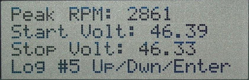


67 59

68 SELECT LOGIN LEVEL This menu selection, allows you to select which access level may enter into the menu system. Use the Up and Down arrow keys to select between each level you wish to enter, and then press the Enter key. Maintenance: This level of security allows for the maintenance person to perform sets / resets of when maintenance was performed. See the Maintenance menu later in this document. Engineering: This level of security allows for a technician to change some of the settings of the Controller. See the Engineering menu later in this document. Password: This level of security will allow you to change the passwords of the Maintenance, Engineering, or do a complete reset of the passwords to default. See the Password Select section later in this document. Each level login has access to the previous level. Maintenance level has access only to that login level. Engineering has access to both Maintenance and Engineering. Password select has access to all levels. There is a 5 minute timeout for the login. If there are no buttons pressed for 5 minutes, the control panel resets to no current login. The Stop and Back Light buttons do not reset the 5 minute timer for the auto logoff. The display does NOT revert back to the main screen at logoff at this time. 60

69 MAINTENANCE PASSWORD ENTRY This item allows you to enter the password for the Maintenance level of menus. Use the Up and Down arrow buttons to increment or decrement the number under the blinking cursor. Use the Enter button to accept that number and advance to the next number. When pressing Enter on the 4 th digit, it will validate the password with the password stored inside the control panel. If the password fails, it will return to the main screen. If the password is accepted, it will advance to the Maintenance menu. The default password for the Maintenance menu is: 0000 This password may be changed in the Password Select section. 61


70 MAINTENANCE MENU The maintenance menu consists of 8 menu screens, shown above. Use the Up and Down arrows to move the blinking cursor up or down to the preferred entry, and then press the Enter button to enter into that menu selection. The last line is always Next or Exit. When selecting Exit, it will bring you back to the main screen. 62


71 RESET MENU ITEMS These menu entries will allow you to reset the run-time accumulated for the selected item. When the oil has been changed, the maintenance person will come into this menu and reset the Oil Change timer. The following resets are available. Oil Change: Resets the counter to display the full time left before the next oil change. Oil Filter Change: Resets the counter to display the full time left before the next Oil Filter change. Air Filter Change: Resets the counter to display the full time left before the next Air Filter change. Fuel Filter Change: Resets the counter to display the full time left before the next Fuel Filter change. Starting Battery Service: Resets the counter to display the full time left before the next service required to the Starting Battery. 63


72 MAINTENANCE SET MENU ITEMS The Maintenance level Set menus allow the maintenance person to change the duration between services. The following items may be changed. Use the Up and Down arrow keys to increment or decrement the values shown on line 2 of the display. Press Enter to store the value. Upon pressing enter, you will be asked if you wish to save the entry. Oil Change: This item will adjust the reference time between oil changes. Oil Filter Change: This item will adjust the reference time between oil filter changes. Air Filter Change: This item will adjust the reference time between air filter changes. Fuel Filter Change: This item will adjust the reference time between fuel filter changes. Starting Battery Service: This item will adjust the reference time between starting battery services. 64


73 SHOW STATUS ITEMS This set of menu items allows you to show or hide entries on the last line of the main screen. Upon entry to each item, the cursor is set to its current setting. When the cursor is blinking next to Yes, then that means that entry will cycle through on the last line of the main window. When the cursor is blinking next to No, then that means that entry will not cycle through on the last line of the main window. While in each entry, the last line will show the current values of that entry. 65
74 Use the Up and Down arrows to move the cursor up or down. Press Enter to store. Available selections are: Fuel level: Shows the percentage of fuel left in the tank. Oil Pressure: Shows the oil pressure from the pressure sensor on the engine, if the engine is equipped with a pressure sensor. Oil pressure switches do not give a value here. Engine Temp: Shows the temperature of the engine, if the engine is equipped with a temperature sensor. Temperature switches do not give a value here. Last KWH: Shows the KWh of the last run of the engine or the currently generated power, if the engine is running and generating power at the time of viewing. Oil Filter: Shows the time left before the oil filter needs to be changed. Values are set / reset via the set / reset menu entries. Oil Change: Shows the time left before the oil needs to be changed. Values are set / reset via the set / reset menu entries. Air Filter: Shows the time left before the air filter needs to be changed. Values are set / reset via the set / reset menu entries. Fuel Filter: Shows the time left before the fuel filter needs to be changed. Values are set / reset via the set / reset menu entries. Starting Battery: Shows the time left before the starting battery needs to be serviced. Values are set / reset via the set / reset menu entries. Starting Battery Voltage: Shows the voltage of the starting battery. Total KWh: Shows the total accumulated KWh that the generator has produced. 66

75 CONTROLLER INFORMATION This item shows the Controller s version and compile flags. Pressing Enter will return you to the Maintenance menu. 67
76 ENGINEERING PASSWORD ENTRY This item allows you to enter the password for the Engineering level of menus. Use the Up and Down arrow buttons to increment or decrement the number under the blinking cursor. Use the Enter button to accept that number, and advance to the next number. When pressing Enter on the 4 th digit, it will validate the password with the password stored inside the control panel. If the password fails, it will return to the main screen. If the password is accepted, it will advance to the Engineering menu. The default password for the Engineering menu is: 8282 This password may be changed in the Password Select section. 68


77 ENGINEERING MENU This set of menus allows you to set various items inside the controller. Use the Up and Down arrows to the desired entry, and press the Enter button to select. The last line will be Next or Exit. Selecting Exit will return you to the main screen. WARNING: Setting some of these settings to values outside their designed range may damage the system! STORAGE CONFIRMATION This window is used to confirm the changes you have made to the set points inside the Engineering menu. Use the Up and Down arrows to select Yes or No. Press Enter to select. 69


78 SET MAX VOLTAGE This option allows you to change the desired max output voltage. Use the Up and Down arrows to increment or decrement the desired voltage. Press the Enter button to advance to the storage confirmation window. Setting this value too high may damage your equipment or the generator! SET MAX CURRENT This option allows you to change the desired max amperage to generate. Use the Up and Down arrows to increment or decrement the desired amperage. Press the Enter button to advance to the storage confirmation window. Setting this value too high may damage your equipment or the generator! 70


79 SET BATTERY CHARGE LIMIT This option allows you to change the desired max amperage to be put into the battery bank. Use the Up and Down arrows to increment or decrement the desired amperage. Press the Enter button to advance to the storage confirmation window. Setting this value too high may damage your equipment or the generator! SET LOW VOLTAGE START This option allows you to change the desired voltage required to trigger the start of the automatic charging cycle. Use the Up and Down arrows to increment or decrement the desired voltage. Press the Enter button to advance to the storage confirmation window. This option is described in more detail in the Controller manual. This option only applies to Automatic mode. 71


80 SET HIGH VOLTAGE STOP This option allows you to change the desired voltage required to trigger the stop of the automatic charging cycle. Use the Up and Down arrows to increment or decrement the desired voltage. Press the Enter button to advance to the storage confirmation window. This option is described in more detail in the controller manual. This option only applies to Automatic mode. SET LOW CURRENT STOP This option allows you to change the desired amperage required to trigger the stop of the automatic charging cycle. Use the Up and Down arrows to increment or decrement the desired amperage. Press the Enter button to advance to the storage confirmation window. This option is described in more detail in the Controller manual. This option only applies to Automatic mode. 72

81 SET WARM-UP TIME This option allows you to change the desired time to run the engine at idle before generating power. Use the Up and Down arrows to increment or decrement the desired time in seconds. Press the Enter button to advance to the storage confirmation window. SET COOL-DOWN TIME This option allows you to change the desired time to run the engine at idle before shutting off. Use the Up and Down arrows to increment or decrement the desired time in seconds. Press the Enter button to advance to the storage confirmation window. This option only applies to Automatic mode. 73
82 SET LOW OIL LOCK-OUT TIME This option allows you to change the desired time to ignore the oil pressure switch and/or oil pressure sensor upon startup of the engine. Use the Up and Down arrows to increment or decrement the desired time in seconds. Press the Enter button to advance to the storage confirmation window. SET START DELAY This option allows you to change the time required for the voltage to be below the Low Voltage Start setting. Use the Up and Down arrows to increment or decrement the desired time in seconds. Press the Enter button to advance to the storage confirmation window. This option only applies to Automatic mode. 74

83 SET STOP DELAY This option allows you to change the time required for the voltage to be above the High Volt Stop setting and below the Low Current Stop setting. Use the Up and Down arrows to increment or decrement the desired time in seconds. Press the Enter button to advance to the storage confirmation window. This option only applies to Automatic mode. SET GLOWPLUG TIME This option allows you to change the time for the glowplug to be on before attempting to start the engine. Use the Up and Down arrows to increment or decrement the desired time in seconds. Press the Enter button to advance to the storage confirmation window. 75


84 SET STARTER CUT-OFF RPM This option allows you to set the minimum RPM the engine must turn before disengaging the starter. Use the Up and Down arrows to increment or decrement the desired RPM. Press the Enter button to advance to the storage confirmation window. Setting this value too high may result in damage to the starter or flywheel! SET IDLE RPM This option allows you to set the RPM to keep the engine at an idle during warm-up or cool-down stages. Use the Up and Down arrows to increment or decrement the desired RPM. Press the Enter button to advance to the storage confirmation window. Setting this value too high may result in lower fuel efficiency and can also force the output voltage too high and damage your equipment or the generator! 76

85 SET MAX RPM This option allows you to set the maximum RPM for the engine to turn before triggering an Over RPM fault and shut off. Use the Up and Down arrows to increment or decrement the desired RPM. Press the Enter button to advance to the storage confirmation window. SET CRANK TIME This option allows you to set the length of time to engage the starter during the engine start sequence. Use the Up and Down arrows to increment or decrement the time in seconds. Press the Enter button to advance to the storage confirmation window. Setting this value too high may result in draining the starting battery if the engine does not start! 77
86 SET CRANK REST This option allows you to set the length of time for the engine to rest between crank attempts. The glowplug is OFF during this time! Use the Up and Down arrows to increment or decrement the time in seconds. Press the Enter button to advance to the storage confirmation window. SET CRANK ATTEMPTS This option allows you to set the number of times to try and start the engine before giving up and setting the Failed Start flag. Use the Up and Down arrows to increment or decrement the number of attempts. Press the Enter button to advance to the storage confirmation window. Setting this value too high may result in draining the starting battery! 78

87 PASSWORD SELECT This item allows you to enter the password for the Password select menu. Use the Up and Down arrow buttons to increment or decrement the number under the blinking cursor. Use the Enter button to accept that number, and advance to the next number. When pressing Enter on the 4 th digit, it will validate the password with the password stored inside the control panel. If the password fails, it will return to the main screen. If the password is accepted, it will advance to the Password Select menu. This password may only be retrieved by contacting: POLAR POWER INC Avalon Blvd. Carson, CA USA Tel: (310) , Fax: (310) You will be required to verify your ownership of the equipment before this password is given! This password is NOT changeable! Below is a section where you may write down passwords you have set inside the control panel, and the password from Polar Power to access the Password Select. Maintenance Password: Default: 0000 Engineering Password: Default:
88 Password Select: Call for password 80

89 PASSWORD SELECT MENU This menu allows you to change the passwords of the Maintenance or Engineering levels and allows you to reset the passwords to factory default. Use the Up and Down buttons to move the cursor to the desired entry, and press the Enter button. Selecting Exit will bring you to the main screen. SET MAINTENANCE PASSWORD This menu item allows you to set the password for the Maintenance menus. Use the Up and Down arrows to increment or decrement the number under the blinking cursor. Press Enter to accept that value and advance the cursor to the next number. Upon pressing enter on the last digit, it will store the password in the control panel. The display WILL NOT give you a validation screen! Write down the password in a safe place! On the prior page there is a section where you can write down your new passwords. 81

90 SET ENGINEERING PASSWORD This menu item allows you to set the password for the Engineering menus. Use the Up and Down arrows to increment or decrement the number under the blinking cursor. Press Enter to accept that value, and advance the cursor to the next number. Upon pressing enter on the last digit, it will store the password in the control panel. The display WILL NOT give you a validation screen! Write down the password in a safe place! Two pages prior to this page there is a section where you can write down your new passwords. RESET ALL PASSWORDS This will reset the Maintenance and Engineering passwords to factory default! The default values are displayed on the appropriate page for each level. Use the Up and Down arrows to move between the Yes and No entries, and press Enter to select to reset the passwords or abort the reset. 82
Exceeding Military Standards without the Cost
 Exceeding Military Standards without the Cost The Supra Digital Control System is a highly integrated control solution that will improve the reliability, serviceability, and remote controllability of DC
User Manual Solar Charge Controller 3KW
 User Manual Solar Charge Controller 3KW Version: 1.3 CONTENTS 1 ABOUT THIS MANUAL... 1 1.1 Purpose... 1 1.2 Scope... 1 1.3 SAFETY INSTRUCTIONS... 1 2 INTRODUCTION... 2 2.1 Features... 2 2.2 Product Overview...
SNMP dedicated to ORVALDI Solar Infini
 SNMP dedicated to ORVALDI Solar Infini User s Manual Management Software for Solar Inverter Table of Contents 1. 2. 3. Overview...1 1.1 Introduction...1 1.2 Features...1 1.3 Overlook...1 1.4 Installation
Idle Timer Controller - ITC515-A Ford Transit Contact InterMotive for additional vehicle applications
 An ISO 9001:2008 Registered Company Idle Timer Controller - ITC515-A 2015-2018 Ford Transit Contact InterMotive for additional vehicle applications Overview The ITC515-A system will shut off gas or diesel
DKG-109 AUTOMATIC MAINS FAILURE UNIT
 Tel: +90-216-466 84 60 Fax: +90-216 364 65 65 datakom@datakom.com.tr http://www.datakom.com.tr DKG-109 AUTOMATIC MAINS FAILURE UNIT FEATURES Automatic mains failure Engine control Generator protection
User Manual. Solar Charge Controller 3KW
 User Manual Solar Charge Controller 3KW 1 CONTENTS 1 ABOUT THIS MANUAL... 3 1.1 Purpose... 3 1.2 Scope... 3 1.3 SAFETY INSTRUCTIONS... 3 2 INTRODUCTION... 4 2.1 Features... 4 2.2 Product Overview... 5
Idle Timer Controller - ITC Freightliner MT45 Contact InterMotive for additional vehicle applications
 An ISO 9001:2008 Registered Company System Operation Idle Timer Controller - ITC805 2013-2018 Freightliner MT45 Contact InterMotive for additional vehicle applications The ITC805 system shuts down idling
SOLAR SMART. 12/24V 20Amp MPPT Solar Charge controller with Ethernet
 SOLAR SMART 12/24V 20Amp MPPT Solar Charge controller with Ethernet Embedded web pages, SNMP support, output port for external Relay board and GSM SMS unit port USER MANUAL PLEASE READ THIS MANUAL CAREFULLY
Idle Timer Controller - A-ITC520-A Ford E Series Ford F250 - F Ford F250 - F550 (*B-ITC520-A) F650/F750
 F650/F750") An ISO 9001:2008 Registered Company Idle Timer Controller - A-ITC520-A 2009-2018 Ford E Series 2008-2016 Ford F250 - F550 2017-2018 Ford F250 - F550 (*B-ITC520-A) 2016-2018 F650/F750 *Uses the Ford 24-Pin
An ISO 9001:2008 Registered Company Idle Timer Controller - A-ITC520-A 2009-2018 Ford E Series 2008-2016 Ford F250 - F550 2017-2018 Ford F250 - F550 (*B-ITC520-A) 2016-2018 F650/F750 *Uses the Ford 24-Pin
ITCEMS950 Idle Timer Controller - Engine Monitor Shutdown Isuzu NPR 6.0L Gasoline Engine
 Introduction An ISO 9001:2008 Registered Company ITCEMS950 Idle Timer Controller - Engine Monitor Shutdown 2014-2016 Isuzu NPR 6.0L Gasoline Engine Contact InterMotive for additional vehicle applications
Section 3 Technical Information
 Section 3 Technical Information In this Module: Engine identification Modes of operation Battery charging and heat manage operation Service and repair procedures Maintenance requirements Engine Identification
DKG-509 AUTOMATIC MAINS FAILURE UNIT
 DKG-509 AUTOMATIC MAINS FAILURE UNIT CANBUS AND MPU VERSIONS DESCRIPTION The controller is a comprehensive AMF unit for single genset standby or dual genset mutual standby operations. The unit is available
Idle Timer Controller - A-ITC620-A Chevrolet Express/GMC Savana
 An ISO 9001:2008 Registered Company Idle Timer Controller - A-ITC620-A1 2009-2018 Chevrolet Express/GMC Savana Contact InterMotive for additional vehicle applications Introduction The A-ITC620-A1 is an
Lingenfelter NCC-002 Nitrous Control Center Quick Setup Guide
 Introduction: Lingenfelter NCC-002 Nitrous Control Center Quick Setup Guide The NCC-002 is capable of controlling two stages of progressive nitrous and fuel. If the NCC-002 is configured only for nitrous,
HGM1780. Automatic Genset Controller USER MANUAL. Smartgen Technology
 HGM1780 Automatic Genset Controller USER MANUAL Smartgen Technology Smartgen Technology Co., Ltd No. 28 Jinsuo Road Zhengzhou Henan Province P. R. China Tel: 0086-371-67988888/67981888 0086-371-67991553/67992951
MAGPOWR Spyder-Plus-S1 Tension Control
 MAGPOWR TENSION CONTROL MAGPOWR Spyder-Plus-S1 Tension Control Instruction Manual Figure 1 EN MI 850A351 1 A COPYRIGHT All of the information herein is the exclusive proprietary property of Maxcess International,
Idle Timer Controller - A-ITC620-A Chevrolet Express/GMC Savana
 Introduction An ISO 9001:2015 Registered Company Idle Timer Controller - A-ITC620-A1 2009-2019 Chevrolet Express/GMC Savana Contact InterMotive for additional vehicle applications The A-ITC620-A1 is an
Sentry Battery Charger. Installation and Operations Manual Section 75
 Sentry Battery Charger Installation and Operations Manual 00-02-0616 03-03-08 Section 75 In order to consistently bring you the highest quality, full featured products, we reserve the right to change our
HGM6320T AUTOMATIC GENERATOR CONTROLLER USER MANUAL
 HGM6320T AUTOMATIC GENERATOR CONTROLLER USER MANUAL Smartgen Technology CONTENT 1 SUMMARY... 4 2 PERFORMANCE AND CHARACTERISTICS... 4 3 SPECIFICATION... 5 4 OPERATION... 6 4.1 LCD DISPLAY... 6 4.2 KEY
Deltran Battery Tender 6V/12V 4Amp 5 & 10 Bank Battery Management System TABLE 1. Length of Cord, Feet AWG Size of Cord
 Deltran Battery Tender 6V/12V 4Amp 5 & 10 Bank Battery Management System Designed for Six-cell and three-cell Flooded/AGM/GEL Lead-Acid Batteries and Four-Cell Lithium Iron Phosphate (LiFePO4) Batteries
DKG-109J AUTOMATIC MAINS FAILURE UNIT
 DKG-109J AUTOMATIC MAINS FAILURE UNIT CANBUS VERSION FEATURES True RMS measurements Automatic mains failure ECU control and monitoring through J1939 CAN J1939 ECU warnings displayed as text Various engine
Product Guide: Series III Pump Control Board Set (RoHS)
") revised 04/08/10 Description: The Series III Pump Control Board Set provides motor drive and pump control for a wide assortment of pumps from Scientific Systems, Inc. The assembly consists of two circuit
revised 04/08/10 Description: The Series III Pump Control Board Set provides motor drive and pump control for a wide assortment of pumps from Scientific Systems, Inc. The assembly consists of two circuit
HGM1780 AUTOMATIC GENERATOR MODULE CONTENT 1. SUMMARY PERFORMANCE AND CHARACTERISTICS SPECIFICATION OPERATION...
 CONTENT 1. SUMMARY...4 2. PERFORMANCE AND CHARACTERISTICS...4 3. SPECIFICATION...5 4. OPERATION...6 4.1. DISPLAY PANEL...6 4.2. LCD ICON INSTRUCTION...7 4.3. DISPLAY INSTRUCTIONS...7 4.4. DISPLAY DESCRIPTION...8
SOLAR INVERTER/CHARGER 1000VA/1500VA/2000VA. Appliances. PC TV Light Electricfan
 SOLAR INVERTER/CHARGER SOLAR INVERTER/CHARGER 1000VA/1500VA/2000VA Appliances 420-00300-02 PC TV Light Electricfan Table Of Contents GENERAL PRECAUTIONS... 1 PERSONNEL PRECAUTIONS... 1 INTRODUCTION...
AT EVO SERIES BATTERY CHARGER
 STANDARD FEATURES 5 YEAR WARRANTY EVO AT Series Battery Charger is HindlePower s next generation SCR-based utility battery charger. This evolutionary product is revolutionary in its design and operation
Model: SE-4020-CA Automatic Battery Charger
 OWNERS MANUAL Model: SE-4020-CA Automatic Battery Charger PLEASE SAVE THIS OWNERS MANUAL AND READ BEFORE EACH USE. This manual will explain how to use the battery charger safely and effectively. Please
HGM6410/6420 AUTOMATIC GENERATOR MODULE WITH J1939 INTERFACE SOFTWARE MANUAL
 HGM6410/6420 AUTOMATIC GENERATOR MODULE WITH J1939 INTERFACE SOFTWARE MANUAL SMARTGEN ELECTRONICS Smartgen Electronic Equipment Co., Ltd No.12 Dongqing Street Zhengzhou Henan Province P.R.China Tel : (0086)-371-67992951
MODEL 520 REMOTE START ENGINE MANAGEMENT SYSTEM
 MODEL 520 REMOTE START ENGINE MANAGEMENT SYSTEM DSE 520 ISSUE 4 4/4/02 MR 1 TABLE OF CONTENTS Section Page INTRODUCTION... 4 CLARIFICATION OF NOTATION USED WITHIN THIS PUBLICATION.... 4 1. OPERATION...
ANALOG CONTROL PANEL
 ANALOG CONTROL PANEL 1. AC VOLTS: Displays generator output in voltage. 2. AC FREQUENCY: Displays the speed of the generator set in Hertz. 3. Percent of Load: Displays percentage of load on the generator.
Guardian Battery Charger Series. Installation and Operations Manual Section 75
 Guardian Battery Charger Series Installation and Operations Manual 00-02-0615 02-29-08 Section 75 In order to consistently bring you the highest quality, full featured products, we reserve the right to
CX-SERIES ADVANCED BATTERY CHARGER
 CX-SERIES ADVANCED BATTERY CHARGER Table of Content 1. IMPORTANT SAFETY INFORMATION... 2 1-1 General Safety Precautions... 2 1-2 Battery Precautions... 2 2. FEATURES... 3 2-1 Battery Charging Curve...
HGM1770 Automatic Generator Control Module OPERATING MANUAL Smartgen Electronic
 HGM1770 Automatic Generator Control Module OPERATING MANUAL Smartgen Electronic CONTENT 1. SUMMARY... 4 2. PERFORMANCE AND CHARACTERISTICS... 4 3. SPECIFICATIONS... 5 4. OPERATION... 6 5. PROTECTION...
Fuel Cell Lab Manual. Non Conventional Energy Systems Facility. Non Conventional Energy Systems Facility. Boiler House
 Fuel Cell Lab Manual Non Conventional Energy Systems Facility Boiler House Department of Mechanical Engineering IIT Kanpur System Description The Nexa system provides up to 1200 watts of unregulated DC
DESCRIPTION AND OPERATION
 Page 1 of 10 DESCRIPTION AND OPERATION AIR DELIVERY DESCRIPTION AND OPERATION The air delivery description and operation is divided into five areas: HVAC Control Components Air Speed Air Delivery Recirculation
PUMP PLUS 2000 PLC MODEL #: PP AUTOMATIC DUAL OUTPUT BATTERY CHARGER INSTRUCTION MANUAL
 INSTRUCTION MANUAL PUMP PLUS 2000 PLC AUTOMATIC DUAL OUTPUT BATTERY CHARGER Supplied with Dual Bar Graph Display MODEL #: 091-237-12-PP INPUT: 120 Volt, 60 Hz, 3.5 Amps OUTPUT BATTERY 1 and 2: 15 or 18
AC CONVERTER / BATTERY CHARGER
 AC CONVERTER / BATTERY CHARGER User s Manual MODEL #: CON120AC12/24VDC Listed to UL 458 and CSA 22.2 NO. 107.1 Standards Contents INTRODUCTION... 3 Important Safety Instructions... 3 1. General Description...
24V HEAVY DUTY JUMP STARTER/ POWER BANK MB3752. Storage. Specifications
 Storage Warning! When not in use store your instruction manual and product in a safe and dry place. Before re-use after storage it is recommended that the product is checked by a suitably qualified person
12V/25A BATTERY CHARGER MAINTAINER / JUMPSTARTER
 12V/25A BATTERY CHARGER MAINTAINER / JUMPSTARTER OWNER S MANUAL Read carefully and understand all ASSEMBLY AND OPERATION INSTRUCTIONS before operating. Failure to follow the safety rules and other basic
EVO SERIES BATTERY CHARGER SERIES BATTERY CHARGER
 EVO SERIES BATTERY CHARGER SERIES BATTERY CHARGER Evo Series battery charger designed with YOU in mind. Evo Series battery charger is a next generation SCR-based utility battery charger. This evolutionary
Energy Division
 Energy Division http://energy.tycoelectronics.com Installation and Operating Manual GEN-TRANS Automatic Generator Transfer Switch Controller with Metering Tyco Electronics UK Limited Crompton Instruments
ATevo SERIES BATTERY CHARGER
 PRODUCT OVERVIEW NEXT GENERATION NEW FEATURES: Interactive LCD display Intelligent self diagnostics NERC Compliant ATevo Battery Charger is the next generation SCR-based utility battery charger. The innovative
Overview of operation modes
 Overview of operation modes There are three main operation modes available. Any of the modes can be selected at any time. The three main modes are: manual, automatic and mappable modes 1 to 4. The MapDCCD
HGM7100N SERIES (HGM7110N/7120N) GENSET CONTROLLER USER MANUAL
 GENSET CONTROLLER USER MANUAL") HGM7100N SERIES (HGM7110N/7120N) GENSET CONTROLLER USER MANUAL SMARTGEN (ZHENGZHOU) TECHNOLOGY CO., LTD. Chinese trademark English trademark SmartGen make your generator smart SmartGen Technology Co.,
HGM7100N SERIES (HGM7110N/7120N) GENSET CONTROLLER USER MANUAL SMARTGEN (ZHENGZHOU) TECHNOLOGY CO., LTD. Chinese trademark English trademark SmartGen make your generator smart SmartGen Technology Co.,
MD10. Engine Controller. Installation and User Manual for the MD10 Engine Controller. Full Version
 MD10 Engine Controller Installation and User Manual for the MD10 Engine Controller. Full Version File: MartinMD10rev1.4.doc May 16, 2002 2 READ MANUAL BEFORE INSTALLING UNIT Receipt of shipment and warranty
12V 160W Folding Portable Solar Panel Kit KDSLR160PNLA User Manual
 12V 160W Folding Portable Solar Panel Kit KDSLR160PNLA User Manual Table of Contents Product Features... 1 Product Components... 2 Product Specifications... 2 LED Indicators... 3 Safety Precautions...
SCC-MPPT Solar Charge Controller
 Solar Charge Controller Quick Guide 200W 300W 400W 600W 850W V. 2.2 1. Introduction solar charge controller uses PWM-based DSP controller to keep the batteries regulated and prevent batteries from overcharging
PowerCommand 2100 digital generator set control
 Specification sheet PowerCommand 2100 digital generator set control Description The PowerCommand 2100 control is a microprocessor-based generator set monitoring, metering and control system. The control
AUTO CHARGE 4000 MODEL #: LOW PROFILE CHARGER AUTOMATIC DUAL OUTPUT BATTERY CHARGER INSTRUCTION MANUAL
 INSTRUCTION MANUAL AUTO CHARGE 4000 LOW PROFILE CHARGER AUTOMATIC DUAL OUTPUT BATTERY CHARGER Unit supplied with this display MODEL #: 091-89-12 INPUT: 120 Volt, 50/60 Hz, 5 Amps OUTPUT: 45 Amps File:
Cannondale Diagnostic Tool Manual
 Cannondale Diagnostic Tool Manual For vehicles (ATV & Motorcycles) equipped with the MC1000 Engine Management System Software CD P/N 971-5001983 Data Cable P/N 971-5001984 POTENTIAL HAZARD Running the
HGM6320T AUTOMATIC GENERATOR CONTROLLER USER MANUAL
 HGM6320T AUTOMATIC GENERATOR CONTROLLER USER MANUAL Smartgen Technology Smartgen Technology Co., Ltd No. 28 Jinsuo Road Zhengzhou Henan Province P. R. China Tel: 0086-371-67988888/67981888 0086-371-67991553/67992951/67992952
Model: OBD-L On-Board-Diagnostics II Memory Saver Detector
 Model: OBD-L On-Board-Diagnostics II Memory Saver Detector OWNERS MANUAL IMPORTANT SAFETY INSTRUCTIONS SAVE THESE INSTRUCTIONS This manual will show you how to use your memory saver detector safely and
SP6. Automatic Battery Charger. Model
 Model SP6 Automatic Battery Charger OWNERS MANUAL PLEASE SAVE THIS OWNERS MANUAL AND READ BEFORE EACH USE. This manual will explain how to use the charger safely and effectively. Please read and follow
Rover Series. Rover 20A 40A Maximum Power Point Tracking Solar Charge Controller
 Rover Series Rover 20A 40A Maximum Power Point Tracking Solar Charge Controller 0 2775 E. Philadelphia St., Ontario, CA 91761 1-800-330-8678 Version 1.5 Important Safety Instructions Please save these
LS1024BP/ LS2024BP. Solar Charge Controller USER MANUAL
 EPSOLAR LS1024BP/ LS2024BP Solar Charge Controller USER MANUAL Thank you very much for selecting our product! This manual offers important information and suggestions with respect to installation, use
Fortress 1 Outdoor Emergency Central Lighting Inverter (CLI) Technical Specifications
 Technical Specifications") Fortress 1 Outdoor Emergency Central Lighting Inverter (CLI) Technical Specifications PART 1 GENERAL 1.1 SUMMARY A. This specification describes a single phase, on-line, double conversion, solid state
Fortress 1 Outdoor Emergency Central Lighting Inverter (CLI) Technical Specifications PART 1 GENERAL 1.1 SUMMARY A. This specification describes a single phase, on-line, double conversion, solid state
DIESEL Engine Fire Pump Controllers Features
 1-1 Printer / Recorder The industrial grade thermal printer is housed in a rugged steel enclosure within the controller. The on/off switch, feed and reset buttons are front accessible. A bi-color status
Model H30 Operation Manual
 Model H30 Operation Manual Model H30 Version 1.0 August 1, 2007 2 135 West Davenport Street Rhinelander WI 54501 Phone: 866.441.7997 Fax: 866.278.0036 info@houstonst.com www.houstonst.com 3 Table of Contents
Models: SP3, SPSS3 Automatic Battery Charger
 OWNERS MANUAL Models: SP3, SPSS3 Automatic Battery Charger PLEASE SAVE THIS OWNERS MANUAL AND READ BEFORE EACH USE. This manual will explain how to use the charger safely and effectively. Please read and
ICON 2 1. FEATURES AND CHARACTEIRICS
 ICON 2 1. FEATURES AND CHARACTEIRICS High end Micro-controller(DSP) technology Wide range of auxiliary supply: 7V to 45Vdc. Low power Consumption : 200 ma @ 12 V DC. Alphanumeric 16X4 or 16X2 LCD display
A39 UNIVERSAL SCR CHARGER
 A39 UNIVERSAL SCR CHARGER ECN/DATE CPN35971 21681 01/18 16816-6/05 15349-03 05/02 14575 02/01 14268 10/00 10400 9/96 106 BRADROCK DRIVE DES PLAINES, IL. 60018-1967 (847) 299-1188 FAX: (847) 299-3061 ISSUE
Installation and Operating Instructions. MPPT Solar System Controller ISC3040
 Installation and Operating Instructions MPPT Solar System Controller ISC3040 ABOUT THIS MANUAL These operating instructions come with the product and should be kept with it as a reference to all user s
Elite Power Solutions Automatic Battery Control (ABC) Operation Manual
 Operation Manual") Elite Power Solutions Automatic Battery Control (ABC) Operation Manual Elite Power Solutions 335 E Warner Rd. STE 3 Chandler, AZ 85225 www.elitepowersolutions.com ABC Operation Manual Page 1 Table of Contents
Elite Power Solutions Automatic Battery Control (ABC) Operation Manual Elite Power Solutions 335 E Warner Rd. STE 3 Chandler, AZ 85225 www.elitepowersolutions.com ABC Operation Manual Page 1 Table of Contents
SCC-MPPT Solar Charge Controller
 Table 3: Charging voltage for 4 types of battery Battery Battery 12V battery system 24V battery system Type Type Code Bulk Floating Bulk Floating Vented 01 14.3 V 13.2 V 28.6 V 26.4 V Sealed 02 14.3 V
4.2 Component Identification
 Digital Control Panels Deep Sea Electronics 5220 4.1 General 4.2 Component Identification 4.3 The YML5220 Controller 4.4 Description of Controls 4.5 Navigation 4.5.1 General Navigation 4.5.2 The Event
Indian Speedometer and Body Control Module Service Tool Users Guide
 Indian Speedometer and Body Control Module Service Tool Users Guide Installing speedometer software to your computer 1. Go to the Indian Motorcycle Website: WWW. Indianmotorcycle.com 2. Log in to Service
Te 803 Electronic Controller. Service, Operation & Technical Information Manual
 Te 803 Electronic Controller Service, Operation & Technical Information Manual WARNING! Technical descriptions and data given in this document are accurate, to the best of our knowledge, but can be subject
HSC940 Genset Controller CONTENTS 1 OVERVIEW PERFORMANCE AND CHARACTERISTICS SPECIFICATION OPERATION KEY FUNCTIONS...
 CONTENTS 1 OVERVIEW... 4 2 PERFORMANCE AND CHARACTERISTICS... 5 3 SPECIFICATION... 7 4 OPERATION... 8 4.1 KEY FUNCTIONS... 8 4.2 INDICATOR LIGHT... 9 4.3 AUTO START/STOP OPERATION... 10 4.4 MANUAL START/STOP
MODEL A96 SERIES. 130Vdc Switchmode Utility Rectifier / Battery Charger. Used with LaMarche Power Cage ECN/DATE
 MODEL A96 SERIES 130Vdc Switchmode Utility Rectifier / Battery Charger Used with LaMarche Power Cage CPN112138 ECN/DATE ISSUE DATE: ECN 17010-12/05 106 BRADROCK DRIVE DES PLAINES, IL. 60018-1967 (847)
SCC-MPPT Solar Charge Controller
 Table 4: Alarm point for low battery voltage table Model Alarm point SCC-MPPT-300 10.5 V SCC-MPPT-600 21.0 V Table 5: Charging hour table for reference Battery Capacity To 90% capacity @ 25A charging current
AUTO CHARGE DUAL MODEL #: AUTOMATIC DUAL OUTPUT BATTERY CHARGER INSTRUCTION MANUAL. Ph: Fax:
 INSTRUCTION MANUAL AUTO CHARGE DUAL AUTOMATIC DUAL OUTPUT BATTERY CHARGER MODEL #: 091-145-12 INPUT: 120 Volt, 50/60 Hz, 3.5 Amps OUTPUT BAT 1: 10 Amps OUTPUT BAT 2: 10 Amps File: IM_091-145-12_revb.indd
EVO AT SERIES BATTERY CHARGER
 EVO AT SERIES BATTERY CHARGER AT SERIES BATTERY CHARGER P R O D U C T PATENT PENDING hindlepowerinc.com 610-330-9000 Evo AT Series battery charger designed with YOU in mind. Evo AT Series battery charger
PUMP PLUS 1000 PLC MODEL #: PP AUTOMATIC SINGLE OUTPUT BATTERY CHARGER INSTRUCTION MANUAL
 INSTRUCTION MANUAL PUMP PLUS 1000 PLC AUTOMATIC SINGLE OUTPUT BATTERY CHARGER Unit supplied with one of these displays MODEL #: 091-215-12-PP INPUT: 120 Volt, 60 Hz, 3.5 Amps OUTPUT BATTERY 1 and 2: 15
SP4 DOCUMENTATION. 1. SP4 Reference manual SP4 console.
 SP4 DOCUMENTATION 1. SP4 Reference manual.... 1 1.1. SP4 console... 1 1.2 Configuration... 3 1.3 SP4 I/O module.... 6 2. Dynamometer Installation... 7 2.1. Installation parts.... 8 2.2. Connectors and
MAXIMIZER-II Progressive Nitrous Controller INSTALLATION AND USER MANUAL. MAXIMIZER-II rev A
 MAXIMIZER-II Progressive Nitrous Controller INSTALLATION AND USER MANUAL i Table of Contents Page 1. Installation Overview...1 1.1 MAXIMIZER-II Power Input...1 1.2 SOLENOID DRIVER Ground...1 1.3 Arming
Application Engineering Europe
 Date of last update: Feb-12 Ref: D7.8.4/0112-0212/E Application Engineering Europe CORESENSE DIAGNOSTICS FOR STREAM REFRIGERATION COMPRESSORS 1/17 1 Introduction CoreSense is an ingredient brand name for
Product Manual. Part Number: MVP-193 Mefi-6 ECU Revision: 1.0
 Product Manual Part Number: MVP-193 Mefi-6 ECU Revision: 1.0 Copyright Controls, Inc. P.O. Box 368 Sharon Center, OH 44274 Phone 330.239.4345 Fax 330.239.2845 www.controlsinc.com TABLE OF CONTENTS PRIOR
Harris IRT Enterprises Digital Resistance Tester Model XP
 Harris IRT Enterprises Digital Resistance Tester Model 5012-06XP Specifications & Dimensions 2 Theory of Operation 3 Operator Controls & Connectors 4 Test Connections 5 Calibration Procedure 6-7 Options
RVS-DN Digital Reduced Voltage Motor Starter
 RVS-DN Digital Reduced Voltage Motor Starter Specification Guide Specification Guide Contents 1.0 Introduction 2.0 Specifications 2.1 Standard Performance Features 2.2 Standard Protection Features 2.3
DKG-707 MULTI GENSET PARALLELLING UNIT WITH J1939 INTERFACE
 DKG-707 MULTI GENSET PARALLELLING UNIT WITH J1939 INTERFACE STANDARD FEATURES Automatic and manual start Multi genset synchronization (up to 8 gensets) Multi genset load sharing (up to 8 gensets) Both
TG350 User Manual. Manual Revision: Min. FW Revision: Date Released: 09/01/ DYNAGEN Technologies Inc
 TG350 User Manual Manual Revision: 1.4.0 Min. FW Revision: 1.42.01 Date Released: 09/01/2014 Table of Contents 1 Introduction 1.1 Specifications... 3 2 Installation 2.1 Terminal s... 6 2.2 Typical Wiring...
Solar Charge Controller
 Table 3: Charging voltage for 4 types of battery Battery Type Battery Type Code SC-600W MPPT Bulk Voltage Floating Voltage Vented 01 28.6 V 26.4 V Sealed 02 28.6 V 26.8 V Gel 03 28.6 V 27.4 V NiCd 04 28.6
Deep Sea Electronics Plc
 Deep Sea Electronics Plc 5120 AUTOMATIC MAINS FAILURE MODULE OPERATING MANUAL Author: Anthony Manton Deep Sea Electronics Plc Highfield House Hunmanby North Yorkshire YO14 0PH England Tel: +44 (0) 1723
Cobra 3 Stand-By Emergency Central Lighting Inverter (CLI) Technical Specifications
 Technical Specifications") Cobra 3 Stand-By Emergency Central Lighting Inverter (CLI) Technical Specifications PART 1 GENERAL 1.1 SUMMARY A. This specification describes a stand-by, three-phase, solid state Lighting Inverter System
Cobra 3 Stand-By Emergency Central Lighting Inverter (CLI) Technical Specifications PART 1 GENERAL 1.1 SUMMARY A. This specification describes a stand-by, three-phase, solid state Lighting Inverter System
Compact Sine Inverter
 Compact Sine Inverter Instructions for installation & use Applies to the following models: Output power: 700watt, 1000 watt, 1500watt, 2000 watt & 3000 watts Output voltage: and output, 50Hz & 60Hz Output
DIN-Rail DC UPS. Powers Loads and Charges Back-Up Battery, Ideal for Automation and Wireless System Transmitter Applications
 DIN-Rail DC UPS Powers Loads and Charges Back-Up Battery, Ideal for Automation and Wireless System Transmitter Applications Combines all system power functions: power supply, battery charger, UPS circuitry
AT30 SERIES BATTERY CHARGER
 STANDARD FEATURES 5 YEAR WARRANTY 5 Year Product Warranty Universal main control board operates in any AT Series charger Alarm assembly with local LEDs and summary relay contact for AC Failure, DC Failure,
Cascade CD101 Auto-Start Controller. Installation and Operations Manual Sections 40 & 75
 Cascade CD101 Auto-Start Controller Installation and Operations Manual 00-02-0594 2018-02-15 Sections 40 & 75 In order to consistently bring you the highest quality, full featured products, we reserve
BATTERY CHARGER CHR-1445
 BATTERY CHARGER CHR-1445 / 2685 TEL:886-4-2238-0698 FAX:886-4-2238-0891 Web Site:http://www.monicon.com.tw E-mail:sales@monicon.com.tw Copyright 2007 Monicon Instruments Co., Ltd. All right reserved. Contents
INSTALLATION INSTRUCTIONS
 INSTALLATION INSTRUCTIONS WARNING: WARNING: www.altronicinc.com DEVIATION DEVIATION FROM THESE FROM INSTRUCTIONS THESE INSTRUCTIONS MAY LEAD MAY TO LEAD IMPROPER TO IMPROPER OP- ERATION OF ENGINE THE MACHINE
An ISO 9001:2008 Registered Company
 An ISO 9001:2008 Registered Company Introduction Engine Monitor System 2009-2018 Ford E Series (EMS501-D) 2008-2010 Ford F250-550 6.2L, 6.8L (EMS506-D) 2011-2016 Ford F250-550 6.2L, 6.8L (EMS507-D) 2017
Defender Mini Online Emergency Central Lighting Inverter (CLI) Technical Specifications
 Technical Specifications") Defender Mini Online Emergency Central Lighting Inverter (CLI) Technical Specifications PART 1 GENERAL 1.1 SUMMARY A. The Defender Mini CLI specification describes a single phase, online, solid state Lighting
Defender Mini Online Emergency Central Lighting Inverter (CLI) Technical Specifications PART 1 GENERAL 1.1 SUMMARY A. The Defender Mini CLI specification describes a single phase, online, solid state Lighting
The Traveler Series: Adventurer
 The Traveler Series: Adventurer RENOGY 30A Flush Mount Charge Controller Manual 2775 E. Philadelphia St., Ontario, CA 91761 1-800-330-8678 Version: 2.2 Important Safety Instructions Please save these instructions.
Installation and Operating Instructions (for chargers shown below)
") Installation and Operating Instructions (for chargers shown below) For additional information please call our Technical Support Group 800.742.2740 PRO CHARGING SYSTEMS, LLC 1551 Heil Quaker Boulevard,
Installation and Operating Instructions (for chargers shown below) For additional information please call our Technical Support Group 800.742.2740 PRO CHARGING SYSTEMS, LLC 1551 Heil Quaker Boulevard,
Installation and Operating Instructions. Solar System Controller ISC3030
 Installation and Operating Instructions Solar System Controller ISC3030 ABOUT THIS MANUAL These operating instructions come with the product and should be kept with it as a reference to all user s of the
OpenEVSE - 40A Charging Station
 OpenEVSE - 40A Charging Station P50 Advanced P50 Standard http://www.openevse.com Read and save these instructions prior to installing and operating your Charging Station. Retain this installation guide
AUTO CHARGE 12 HO MODEL #: MODEL #: MODEL #: AUTOMATIC SINGLE OUTPUT BATTERY CHARGER INSTRUCTION MANUAL
 INSTRUCTION MANUAL AUTO CHARGE 12 HO AUTOMATIC SINGLE OUTPUT BATTERY CHARGER MODEL #: 091-170-6 MODEL #: 091-170-12 MODEL #: 091-170-24 File: IM_091-170-xx_revd.indd Rev: D Revised By: MFG Date: 10-23-2013
CORESENSE DIAGNOSTICS FOR STREAM REFRIGERATION COMPRESSORS
 Date of last update: Apr-15 Ref: D7.8.4/0112-0415/E Application Engineering Europe CORESENSE DIAGNOSTICS FOR STREAM REFRIGERATION COMPRESSORS CoreSense Diagnostics for Stream Refrigeration Compressors...
Using Apollo Solar Remote Monitoring Software
 Using Apollo Solar Remote Monitoring Software Apollo Solar, Inc. 23 F. J. Clarke Circle Bethel, Connecticut 06801 USA +1 (203) 790-6400 www.apollosolar.com 1 Overview We will see how all the components
OPERATING INSTRUCTIONS MCP-MT1
 OPERATING INSTRUCTIONS MCP-MT1 MRM PROCOM Pvt Ltd ISO-9001-2008 certified organization Plot No. : 20-21, Industrial Estate, Sector - 59, Phase-II, Faridabad (Haryana) Ph.: 0129-4700400(10 Lines) Email: