Exceeding Military Standards without the Cost
|
|
|
- Margery Ray
- 6 years ago
- Views:
Transcription


1 Exceeding Military Standards without the Cost The Supra Digital Control System is a highly integrated control solution that will improve the reliability, serviceability, and remote controllability of DC Generator based power systems. The Supra Controller can control power to DC loads and serve as a fuel based programmable battery charging system. The Supra Control System Integrates: Engine Control Alternator Voltage Regulation Auxiliary Power Inputs Operator Interface Remote Site Monitoring and Communications The Supra s high level of circuit integration eliminates separate and independent control modules, simplifying the wire harness and eliminating the typical conflicts between modules integrated from different manufactures. It can be: remotely controlled, monitored, calibrated, and tested, through an industrial modem, cell phone modem, or Ethernet. Communication is accessible locally with a PC Laptop or remotely through the Internet to facilitate site support and reduce costly visits to the site. The Supra provides a complete log of alarms and operating parameters at the completion of a charge cycle or shutdown due to a fault condition. Alarms can be reset and the generator exercised remotely to help identify potential problems before scheduling a site visit. If an unscheduled maintenance is required, the technician can arrive at the site prepared, reducing the need for a second visit. The Supra facilitates Hybrid Systems incorporating other sources of power including solar, wind, hydro, and utility. All connections to the controllers are through Amp/Tyco Circular C type connectors facilitating on-site repair through controller swapping (plug and play). The controller circuits were designed to meet the most stringent Military and Telecommunications requirements for EMI, EMP, and Ripple. The Supra Controller can meet the requirements of any type of grounding requirement: negative, positive, or float.
2 Supra Advantages 1. Optically isolated RS 232 and CAN bus communications allow the generator to be controlled (locally or remotely) through a PC computer with Polar s GUI or the customer s own CAN bus. 2. Precision battery charging using control of both the voltage and current output. Battery charging using a single parameter of voltage control is insufficient because small millivolt changes can cause undesirable, large current fluctuations. 3. User configurable battery charging algorithms for different battery technologies. User configurable: current limit in bulk charge, temperature compensation curves, differentiation of load current and battery charge, and float voltages. 4. Control of Engine: RPM, starter motor, glow plugs, choke, fuel racks, fuel and engine block heaters, and cooling fans. Accurate monitoring of temperatures, pressures, coolant, and fuel levels. 5. Digitally controlled variable parameters: Digital control allows the generators, voltages, currents, engine speeds, and sensor calibrations to be remotely calibrated. All potentiometers were eliminated 6. Set points and recalibration can be performed remotely through the Internet, RS 232, Ethernet, or Cell Phone Modem using Polar s GUI interface. 7. Software is field upgradeable bit A/D converters and optically isolated linear amplifiers provide accurate voltage, current, fuel level, oil pressure, temperature, and engine speed measurements. 9. Sensor and communications ports are isolated, so the failure of an input sensor or communications port will not contribute to system conflicts and issues. 10. High immunity to electrical noise. Sources of noise include the starter motor, spark plugs, lightning, coupling of AC sources, cell phone transmissions, microwave, and radar transmissions. 11. Very low conductance and radiation of EMI: A clean DC Power Source is incorporated for the provisioning of sensors, field coils, and actuators with a resultant effect of a reduced EMI source. This is unlike other controller manufacturers, who typically use an unfiltered PWM source of power. Polar Power also increases EMI suppression by housing the three models 250, 290 and 320 in sealed Aluminum enclosures. 12. Polar s unique circuit provides reliable operation in floating, positive, or negative ground systems. Polar uses switching power supplies to isolate both the positive and negative inputs. Most other controllers use a lower cost 3-pin voltage regulator that creates problems when moving between positive and negative ground systems. 13. The power supplies input and output signals and is fully isolated for up to 1500 Volts, via opto and galvanic couplers. The Supra Control System can tolerate most Hipot testing with controls connected in place. 14. Superior high voltage and current surge immunity from lightning, alternator surges, and load dumps with active voltage clipping circuits. 15. Supra s microprocessor and relays are able to operate under low voltage conditions during engine cranking with a starting battery in poor condition. 16. AMP / Tyco Circular C type connectors are used to maintain a high degree of reliability and provide ease of field service. Signal pins are gold plated and power pins are silver plated, providing low maintenance operation in high humidity, salt fog, and sandy environments. 17. Model 250 and 290 enclosures are gasket sealed to IP Conformally coated circuit boards: all components are soldered in place, except for fuses in the Model 290 module. 2
")
")


3 RS-232 or CAN Bus Communications 320 Operator Interface (remote option) CAN Bus 250 Engine Controller with 320 Operator Interface (local option) Model 290 Engine Interface CAN Bus Battery Temperature, Remote Voltage sense Diode Bridge Assembly Diode Temperature, Engine Speed, Output Current and Output Voltage Alternator Temperature CAN Bus Option Engine Speed Control Engine Temp and Oil Pressure Relays and Switch Contacts Load Current Electrical Load 3


4 Complete Supra Control System 250 Controller 290 Engine Interface 320 Operator Interface Sensors and Cable Harnesses Software Model 250 Controller This module is the heart of the system providing the primary logic control, analog and switches inputs, communication, and the generator output regulation. On board the Model 250 is a 15 amp bipolar power supply controlled by the microprocessor to provide the generator s voltage and current regulation. Regulation is achieved either through controlling the field coil as required by the Model 6200 alternators or through an actuator on the engine for speed control as required by the Model 8000 series. The Model 250 also has two RS-232 ports. These ports are optically isolated from the system voltage and are used for communicating with the: Model 380 Ethernet module, Cell Phone module, PC type Computer, or other customer devices. The Model 250 facilitates Hybrid systems incorporating other charging sources of power including solar, wind, hydro, and utility. Model 290 Engine Interface This assembly contains the relays and switched contact inputs for the engine control as required for fully automated operation. The 290 was designed as a separate module to facilitate access to replaceable fuses used to protect the system against catastrophic damage from shorts, over current, or operator error. Starter solenoids, fans, glow plugs, and fuel valves are typical devices that are fuse protected within the 290 module. Analog to digital converters read the various engine, alternator, and control sensors for temperature, pressure, voltage, current, and speed. Through software, the 8 on board relays and 3 switch inputs can be assigned various functions encompassing: engine speed control, fuel valves, cooling and ventilation fans, engine block heaters, fuel heaters, safety shut down devices, and the normal functions required by a diesel or LPG fueled engine. 5 switch inputs to monitor: intrusion, over temperatures, presence of AC grid, solar or wind power, fuel leaks, or other special requirements. The Model 250 Controller communicates with the 290 Engine Interface, the 320 Operator Interface, and accessory modules through a CAN bus interface. CAN bus interface is open to users for transmitting operational data or receiving control commands from the user s CAN bus system. The CAN bus protocol is unique to Polar Power. 4

5 Complete Supra Control System Model 320 Display / Keyboard Provides the operator an interface for changing parameters and viewing system status via a 4 line, 20 character display screen. The Model 320 can either be installed on the case of the Model 250 Controller or within its own enclosure. The Model 320 can be located up to 35 meters from the Model 250. Model 250 Controller Voltage Control Range The Supra System can operate generator systems with output voltages of 12 to 600 Vdc. An accessory voltage divider module is required for voltages over 70 Vdc. Output Power Control Range There are no maximum power output limitations for Generators operated by the 250 Controller. Input Voltage A 16 to 72 Vdc input is required to power the Model 250 Controller. The Model 250 can derive its operating power from the starting battery or the load battery. The load battery is preferred as the Controller s source of power because it is typically a more reliable source than the starting battery. 12 Vdc systems require a boost converter, and for systems over 70 Vdc a buck converter is required to power the Model 250 Controller. Voltage dividers for voltage and power input conditioning are utilized for high voltage generator systems (70 to 600 Vdc). Quiescent Power Consumption. The Model 250 has very low power consumption requirements are typically less than 2 watts in the idle mode. Wide Range of Sensor and Control Accessories Battery monitor, fuel level or pressure, temperature, pressure sensors, voltage, current, oil pressure, oil level, coolant level, enclosure over temperature, air filter restriction, etc. are available to meet the needs of specific applications. Software Internal to the Supra using C Sharp. The Supra Controller has an optional Graphic User Interface (GUI) that allows complete remote control over the DC generator system. There is the capability to remotely change voltage, current, stop and start parameters, and reset alarms. Our Ethernet module option has password security and offers SNMP communication, which facilitates IT management of the site. Power Required for Engine Speed Control for 8000 Series Alternators When regulating engine speed, the Supra can consume up to 80 watts of power driving the actuator on the fuel rack or the butterfly valve on the carburetor, depending on the type of engine and actuator used. Power Required for the Field Coil for Series 6200 Alternators Using a high efficiency DC-DC power supply the Supra can output up to 350 Watts of power for driving the alternator s field coil. The field coil is used to regulate voltage and current output of the generator. Electrical Isolation The controller has a total of 8 isolated power supplies for the microprocessor / internal logic, analog to digital conversion, sensor / transducers, and communications. Power supplies are fully isolated on both the positive and negative pathways. This feature is essential for Telecom systems operating in positive ground 48 Vdc systems, but is not present in most other systems. Communication between modules The Supra system uses it own CAN bus communication protocol (125 Kbs) to send and receive data and commands 5
6 Model 250 Controller (cont) to the modules in the system. The Supra Controller uses the Microchip MCP2515. Upgrades Serial programming updates with the Polar Bootloader. Current Measurement Hall Effect current transducers are incorporated in the design to replace standard shunts for enhanced electrical isolation, precise measurements, and to eliminate the cooling requirement for hot shunt surfaces. The 250 Controller has multiple current sensor inputs that can be used for generator, battery, solar, wind, or load measurements. Operational Environments The Supra System is rated at -40 to +60 Celsius. All electronic components used in the circuits are rated for a minimum service of -40 to 85 C. The microprocessor is rated to 125 C. The control modules can handle a humidity range from 0% to condensing and altitudes up to 14,000 feet. Durability / Reliability Power components are derated by at least 50% whenever possible (per Military standards). Only 5 electrolytic capacitors are used in the Supra Controller. Avoiding electrolytic capacitors provides for long term reliability and reliable operation over wide temperature ranges. Temperature Measurement A KTY-83 sensor is used for accuracy and enhanced electrical isolation. The 250 Controller has a total of 4 temperature sensor inputs that can be used for engine, alternator, enclosure, and battery temperature compensation. Pressure Measurement Solid state pressure transducers (no moving parts) were selected by Polar for their high reliability and accuracy. Other pressure senders (Bourdon tube and viable resistor) have a shorter life expectancy, especially on diesel engines. Polar incorporates solid state pressure transducers to measure fuel tank level and oil pressure. Fuel Level Monitor Option Polar calculates fuel level in the tank by measuring the column weight of fuel in the tank. A Very accurate (1%) solid state transducer performs this task through a location outside and at the bottom of the fuel tank. Knowing the weight of the fuel column at the top (full) and bottom (empty) of the tank provides us with a percentage of fuel in the tank. The Supra can provide and display an accurate fuel level for any size tank without relying on mechanical devices. The Supra Controller records the fuel level percent at the start and end of each run cycle. The controller also measures the amount of kilowatt hours produced during the run cycle. Generator efficiency can be easily calculated using these two values. The fuel level option can also alert the operator to theft or leakage of fuel. Cooling and Enclosure Purging For safety the Supra Controller can run vent or radiator cooling fan(s) to remove possible flammable vapors from the enclosure before starting the engine. The Supra Controller also monitors the coolant temperature while the generator has cycled off. If the temperature is above the set point the vent fans will run to cool the enclosure and generator. This will prevent the generator from heating up the enclosure after it has shut down. This feature also extends the life and reliability of the generator. While cycled off and exposed to the Sun, the enclosure s temperature can climb to over 100 C, the vent fans can automatically cycle on to reduce the temperature. Kilowatt and Amp Hour Produced The Supra 250 Control System monitors the voltage and current then accumulates Kilowatt and Amp Hour values in the log file. Battery Monitor Option The Battery Monitor harness accessory includes a current transducer, temperature sensor, and two wires for remote voltage sensing. The Battery Monitor remote option also can automatically compensate for line loss. Digital Switch Inputs There are 5 optically isolated switch closure inputs for: fuel leak, enclosure intrusion, low fluids (oil and coolant), fire alarm, low fuel, etc. The CAN Bus Capable of connecting up to 128 nodes in a daisy chain fashion over a distance of up to 100 meters. Signal inputs and control outputs can be expanded via the CAN bus. Engine Speed Engine Speed is measured through the alternator frequency. Most automatic generators use a magnetic pickup on the flywheel s ring gear to sense speed; however, this creates a maintenance and reliability problem when small chips of steel or other iron particle collect on the tip of the pickup sensor and short the measurement. This is not a problem when using the magnets and stator inside the alternator for engine speed sense. 6
 and 24 Vdc (14 to 32 Vdc).")

7 Model 250 Controller Dimensions Model 250 Controller with the model 320 Operator Interface integrated Model 290 Engine Interface Operating Voltage The model 290 derives its power from the starting battery. Available in two versions 12 Vdc (7 to 16 Vdc) and 24 Vdc (14 to 32 Vdc). The low voltage capability of the Model 290 allows it to remain in operation during engine starting with a starter battery in poor condition. Relays The Model 290 has 8 output relays which are controlled by the Supra 250 via the CAN bus. Multiple Model 290 modules can be daisy chained for increased capacity. Each module has 2 signal relays (Gold plated contacts) for alarms and 6 power relays (Silver plated contacts) that can be used for: speed controls, cooling fans, ventilation louvers, ignition, fuel racks, pumps, solenoids, block and enclosure heaters, starter, glow plugs, as well as other system needs. Relay field coils are monitored for open and shorted circuits. Fuses and Switch Currents Power relays have dedicated fuses on the output for safety and system reliability. The 290 module has two 70 amp current relays with fuses, one 40 amp relay with fuse, two 10 The 250 Controller and the 290 Engine Interface have the same dimensions and construction. amp relays with fuses, and one 10 amp relay without a fuse. There are also two signal relays, which are rated at 1 amp and are without fuses. Analog Input The Model 290 measures starting battery voltage. Digital Switch Inputs There are 3 optically isolated switch inputs used for over temperature, oil, and air filter restriction. Model 320 Operator Interface Module Characters: 7 or 8 data bits Parity: Odd, Even, None Stop Bits: 1 or 2 Modem Control Signals: CTS, RTS, DTR/DCD vflow Control: XON/XOFF (software), CTS/RTS (hardware) Programmable IO: 3 GPIO pins (software selectable) Indicators (LED) Link & Activity indicator 7
8 Security SSLv3 and SSHv2 Client & Server, Selectable 128/256/512/1024 Bit certificates Encryption: AES, 3DES and RC4 Authentication: SHA-1, MD5, Base-64 User Access Lists The LCD display on the 320 Module is back-lit with white LEDs. The back light is switch controlled for on / off and brightness. The CAN bus allows the Model 320 to be located up to 100 meters away from the 250 Control module. The Model is powered through the CAN bus power. Model 380 Ethernet Interface Module Our Ethernet module option connects to the RS-232 port on the Model 250 Supra Controller and provides the means of connecting to a hub or switch. Features include: Password security for access restriction to the generator Serial to SNMP Ver. 2c or 3 conversions Dual path communication for SNMP data and Polar GUI Interface Opto couple isolation between the RS-232 and the Ethernet output Power input is fully isolated, 8 to 65 Vdc. On board memory 8MB SDRAM/16MB Flash Serial Interface Software selectable data rates from 300 to 921kbps VIP Access Enabled Seamless integration with ManageLinx remote service enablement platform Software Windows 98/NT/2000/XP/Vista-Based Device Installer ComPort Redirector Secure ComPort Redirector Management Internal Web Manager (SSL Option for secure login) CLI (over Serial Ports, Telnet or SSH) XML Configuration Records via CLI or FTP DeviceInstaller software Firmware: Upgradeable via FTP, Web, and Serial Port Flash wear leveling and erase cycle statistics Internal Web Server Customizable with CGI Web content on local file system and updatable through FTP Power 9 Vdc to 72 Vdc Fully isolated to 1500 Volts Environmental Extended Temp: -40 to 85 C (-40 to 185 F) Regulatory Approvals FCC Part 15, Subpart B, Class B ICES-003 Issue 4 (2004), Class B EN55022:2006 and EN55024: A1: A2:2003 AS/NZS CISPR22:2006 VCCI V-3/ EN :2006, EN :1995+A1:2001+A2:2005 8
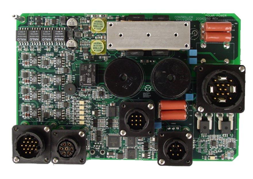
9 250 Controller 9
10 290 Engine Interface 10
11 Charging Control Alternator Voltage Alternator Current Battery High Voltage Stop Battery Low Current Stop Engine Stop Delay (0 32,767) Bat Low Voltage Start Engine Start Delay (0 32,767) Battery Monitor, Optional Temperature Compensation Volts per Degree Reference Temperature Min Temp Compensation Volts Max Temp Compensation Volts Battery Over Temperature Charge Termination Description Sets the voltage output of the alternator Sets the maximum current output Sets the voltage that the battery must reach to start the shutdown sequence, the next stage in shut down is the Low Current Stop Sets the value that the output current must be equal to or below to continue the shutdown sequence Sets the seconds that the generator can continue to run after the High Voltage Stop and the Battery Low Current Stop conditions have been satisfied. This countdown timer completes the charge cycle. The voltage that the battery must be at or below, before starting the timers for a start sequence Sets the seconds that the battery voltage must be at or below the Low Voltage Start, before initiating the start sequence. Description Enabling this option will adjust the Max Voltage output from the alternator, according to the battery temperature. This value is the voltage shift per degree of the battery temperature. This is the baseline temperature value; battery temperature rising above this value will cause the voltage to decrease by the volts per degree value. Temperatures below this value will cause the voltage to increase. This is the lowest voltage that the temperature compensated adjustment will be limited to. This is the highest voltage that the temperature compensated adjustment will be limited to. This is the maximum temperature the batteries can reach, before terminating the charge cycle. This will trigger a Battery Over Temperature Fault Alarm. 11
12 Max Charging Current This is the maximum current charge into the battery. It is calculated from the difference between the output of alternator and the load current. Generator Start / Stop / Run Engine Warm-up Time (0 255) Engine Cool Down Time (0 255) Starter Motor Disengage RPM / Min RPM Low Speed charging suspension Description Seconds to hold the engine at idle (speed controlled engines) or keep the field coil un-energized (fixed RPM engines) after the engine has started Seconds to hold the engine at idle (speed controlled engines) or keep the field coil un-energized (fixed RPM engines) before the engine stops The RPM value that defines that engine has started and disengages the starter. If the engine is in a run sequence and the RPM drops below this level, it will trigger a Low RPM fault alarm. If the engine speed drops below this value, the charging is suspended until the speed recovers and 15 seconds pass. For 6200 Series Alternators only, not necessary for 8000 Series. Max RPM The maximum RPM before triggering the Over RPM fault. The fuel supply and / or the ignition is then shut off and Over-speed alarm is generated. Idle RPM Sets the RPM during the warm up period. This is only available for 8000 Series Alternators. For multi-speed 6200 Alternators this function in within a secondary controller. Crank Time Crank Rest Time Crank Attempts Lube Oil Pressure Ignore Glow Plug Pre-Heat Seconds to keep the starter engaged. If RPM is at or above the Cutoff RPM, it overrides this value and disengages the starter. Sets the seconds between failed starts due to Crank Time expiring. The glow plug is OFF at this time. Sets the number of attempts to start the engine, before aborting and triggering a Failed Start fault Alarm Seconds to ignore the oil pressure switch or oil pressure sensor. If after this time expires and the switch or sensor still shows low oil, the engine will shutdown, and trigger a Low Oil fault alarm. Sets the Glow Plug Pre-Heat duration in seconds. This feature is used only if the Glow Plug Temperature Compensation option is not selected. If the Temperature Compensation is selected, this is the value to keep the glow plug engaged after the engine has started to accelerate warm up. 12
13 Temperature regulated Glow Plug Preheat (1-29 seconds) Auto Vent Fan Temperature The pre-heat for the glow plugs is determined by the engine coolant temperature. At -20 C and lower pre-heat is 29 sec and 40 C and higher the Pre-heat is 1 second. This sets the temperature that the vent or radiator fan(s) will start to cool the generator and / or the enclosure. Once the temperature drops below that value, the vent fan will disengage. The vent fan may come on at any time. Auto Vent Fan Delay Sets the seconds on the vent fan run before starting the generator and how long to keep the vent fan running after the generator has started. If the engine coolant temperature is above the Auto Vent Fan Temperature setting, the count-down timer at the end of the run cycle will not count down until after the engine has cooled off below the set point. Fuel Level Monitor, Optional Description Fuel Level Alarm Set Value The percent at which the fuel tank will trigger a low fuel alarm. Defaults to 25%. Low fuel can either provide maintenance alarm or shutdown engine. Fuel Tank Calibration Sets the empty and full calibration points of the fuel container. The controller and fuel transducer will interpolate the percentages of fuel between the two calibrated points. Engine Analog Inputs, Model 250 Low Oil Pressure, Transducer High Engine Temperature, Sensor Engine Switch Inputs Model 290 Coolant Level Sets the minimum operating oil pressure. If the oil pressure drops below this value, it will trigger a Low Oil fault and an alarm event will shutdown the engine. Sets the maximum coolant temperature. If temperature rises above this value it will trigger an Over Temp fault and an alarm event will halt the engine. Limit 3 Inputs, Description SW6. Through an optional level switch in the radiator, this feature can provide a maintenance warning on low coolant level. Alarm event will provide maintenance warning. 13
14 Hi Temperature, Switch Air Filter Restriction, Switch Low Oil pressure, Switch SW7. Monitors either: engine coolant, oil, or enclosure. Alarm event will shut down engine. SW8. Using a vacuum switch we can sense air restriction in the engine air intake filter. An alarm event will provide a maintenance warning. SW6. Low oil level using pressure switch in place of the oil pressure transducer. An alarm event will shut down engine. System Switch Inputs Model 250 Fuel Tank Leak Limit 5 Inputs, Description With a leak detector switch, this can be hooked up to either SW1 or SW2 to trigger a maintenance warning when it detects a leak. Shut Down Engine Intrusion Alarm Emergency Stop Remote Stop SW3 is used for the presence of alternate power input for charging the batteries. If the unit has started with this switch open and then it closes from an external power detection, it will shut the engine down normally. If the unit has started with this switch closed, the unit will continue to do a full run cycle. Examples of alternate power are: AC line, or Solar / Wind availability SW1 and SW2 are customer customizable in the GUI. SW4 SW5 Weekly/ Monthly Exercise Exercise Rate Exercise Day Exercise Duration Exercise Time This setting has 3 selections: None, Weekly, Monthly. This setting has different values depending on the Exercise Rate setting. Weekly will give the days of the week, and Monthly will give the days of the month. This is the time in minutes to run the system on the scheduled Rate, Day, and Time. These two values set the hour and minute for the system to start the Exercise on the day selected by the Rate and Day settings. 14
15 Service Settings Oil Change Oil Filter Change Air Filter Change Start battery Service Fuel Filter Change Time in Engine Run-time Hours between oil changes Time in Engine Run-time Hours between oil filter changes Time in Engine Run-time Hours between air filter changes Time in Engine Run-time Hours between services of the Starting Battery Time in Engine Run-time Hours between fuel filter changes Data Available on the Display Starting Battery Voltage Controller Version and Compile Flags Date and Time Engine Run-Time Hours RPM KWh Current / Last Run KWh Accumulated Fuel level Oil Pressure Engine Temperature Diode Bridge Temperature Alternator Temperature Controller Temperature This is the actual voltage of the starting battery in the system. This shows the current firmware version of the controller, GUI, and what compile flags were used. Date and Time inside the controller Accumulated hours, minutes, and seconds that the engine has run Actual RPM of the engine This shows how many KWh were produced during the last run, or if it is running, the current KWh for this run. This value goes to 0 upon startup sequence. This shows the total accumulated KWh that the system has produced. This shows the fuel level, in percent, that is left in the fuel container. Actual oil pressure being read by the Oil Pressure Sensor, if equipped Actual temperature of the engine, read by the Engine Temperature Sensor, if equipped Actual temperature of the Diode Bridge Actual temperature of the Alternator Actual temperature inside the controller 15
16 Power Reduction Settings Engine Temperature Supra Controller Over Temp Diode Bridge Temperature Battery Temperature Alternator Temperature Alarm Contacts, Dry Contact Closure Generator Fail Generator Warning Speed control for 6200 Series Only The temperature at which the system will cut the power output in half, to try to lower the engine temperature (in future updates, it will set a warning). Once it is below this value, it will resume full power. If the temperature continues to rise to the second set point, the system will shutdown with an over temperature alarm. The temperature at which the system will cut the power output in half, to try to lower the internal temperature of the controller (in future updates, it will set a warning). Once it is below this value, it will resume full power. The temperature at which the system will cut the power output in half, to try to lower the diode bridge temperature (in future updates, it will set a warning). Once it is below this value, it will resume full power. The temperature that the system will cut the power output in half, to try to lower the battery temperature (in future updates, it will set a warning). Once it is below this value, it will resume full power. The temperature that the system will cut the power output in half, to try to lower the alternator temperature (in future updates, it will set a warning). Once it is below this value, it will resume full power. Either the speed control or Generator Status is available K8 is the fault relay that is tripped when any of the above fault conditions occur. To clear this fault, you must toggle between Automatic and Manual mode. On some models that use multi-speed engine control, this fault relay is not used for faults. K7 is the warning relay that is tripped when any of the above warning conditions occur. This relay will disengage when the warning has cleared, either on its own or by user intervention. On some models that use multi-speed engine control, this warning relay is not used for warnings. On some models, K7 and K8 are used to change the RPM of the engine to a predetermined set speed, via digital output. The values can be: off - off off - on on - off on - on 16
17 Hi Temperature, Switch Air Filter Restriction, Switch Low Oil pressure, Switch SW7. Monitors either: engine coolant, oil, or enclosure. Alarm event will shut down engine. SW8. Using a vacuum switch we can sense air restriction in the engine air intake filter. An alarm event will provide a maintenance warning. SW6. Low oil level using pressure switch in place of the oil pressure transducer. An alarm event will shut down engine. System Switch Inputs Model 250 Fuel Tank Leak Limit 5 Inputs, Description With a leak detector switch, this can be hooked up to either SW1 or SW2 to trigger a maintenance warning when it detects a leak. Shut Down Engine Intrusion Alarm Emergency Stop Remote Stop SW3 is used for the presence of alternate power input for charging the batteries. If the unit has started with this switch open and then it closes from an external power detection, it will shut the engine down normally. If the unit has started with this switch closed, the unit will continue to do a full run cycle. Examples of alternate power are: AC line, or Solar / Wind availability SW1 and SW2 are customer customizable in the GUI. SW4 SW5 Weekly/ Monthly Exercise Exercise Rate Exercise Day Exercise Duration Exercise Time This setting has 3 selections: None, Weekly, Monthly. This setting has different values depending on the Exercise Rate setting. Weekly will give the days of the week, and Monthly will give the days of the month. This is the time in minutes to run the system on the scheduled Rate, Day, and Time. These two values set the hour and minute for the system to start the Exercise on the day selected by the Rate and Day settings. 17
Volume Supra Digital Control System
 Volume 5 Supra Digital Control System PROGRAMMING AND USERS MANUAL P R O G R A M M I N G A N D U S E R S M A N U A L Supra Digital Control System Polar Power Inc. 22520 Avalon Blvd., Carson, CA 90745 Fax:
GCU-10. Automatic Engine Control Unit Operators Manual
 GCU-10 Automatic Engine Control Unit Operators Manual KUTAI ELECTRONICS INDUSTRY CO., LTD. TEL : +886-7-8121771 FAX : +886-7-8121775 Website : www.kutai.com.tw Headquarters : No.3, Lane 201, Chien Fu St.,
ANALOG CONTROL PANEL
 ANALOG CONTROL PANEL 1. AC VOLTS: Displays generator output in voltage. 2. AC FREQUENCY: Displays the speed of the generator set in Hertz. 3. Percent of Load: Displays percentage of load on the generator.
Application Engineering Europe
 Date of last update: Feb-12 Ref: D7.8.4/0112-0212/E Application Engineering Europe CORESENSE DIAGNOSTICS FOR STREAM REFRIGERATION COMPRESSORS 1/17 1 Introduction CoreSense is an ingredient brand name for
CORESENSE DIAGNOSTICS FOR STREAM REFRIGERATION COMPRESSORS
 Date of last update: Apr-15 Ref: D7.8.4/0112-0415/E Application Engineering Europe CORESENSE DIAGNOSTICS FOR STREAM REFRIGERATION COMPRESSORS CoreSense Diagnostics for Stream Refrigeration Compressors...
GENSET CONTROL MODULE LEVEL 0 A120A. User selectable time delays for engine start and engine stop (cool down).
.") Technical Data Sheet GENSET CONTROL MODULE LEVEL 0 A120A Features: One model for both spark ignition and diesel engines. 4-alarm light outputs with automatic lamp-test provision. Overspeed adjustment not
Technical Data Sheet GENSET CONTROL MODULE LEVEL 0 A120A Features: One model for both spark ignition and diesel engines. 4-alarm light outputs with automatic lamp-test provision. Overspeed adjustment not
HGM6410/6420 AUTOMATIC GENERATOR MODULE WITH J1939 INTERFACE SOFTWARE MANUAL
 HGM6410/6420 AUTOMATIC GENERATOR MODULE WITH J1939 INTERFACE SOFTWARE MANUAL SMARTGEN ELECTRONICS Smartgen Electronic Equipment Co., Ltd No.12 Dongqing Street Zhengzhou Henan Province P.R.China Tel : (0086)-371-67992951
MD10. Engine Controller. Installation and User Manual for the MD10 Engine Controller. Full Version
 MD10 Engine Controller Installation and User Manual for the MD10 Engine Controller. Full Version File: MartinMD10rev1.4.doc May 16, 2002 2 READ MANUAL BEFORE INSTALLING UNIT Receipt of shipment and warranty
RVS-DN Digital Reduced Voltage Motor Starter
 RVS-DN Digital Reduced Voltage Motor Starter Specification Guide Specification Guide Contents 1.0 Introduction 2.0 Specifications 2.1 Standard Performance Features 2.2 Standard Protection Features 2.3
AT EVO SERIES BATTERY CHARGER
 STANDARD FEATURES 5 YEAR WARRANTY EVO AT Series Battery Charger is HindlePower s next generation SCR-based utility battery charger. This evolutionary product is revolutionary in its design and operation
DKG-109 AUTOMATIC MAINS FAILURE UNIT
 Tel: +90-216-466 84 60 Fax: +90-216 364 65 65 datakom@datakom.com.tr http://www.datakom.com.tr DKG-109 AUTOMATIC MAINS FAILURE UNIT FEATURES Automatic mains failure Engine control Generator protection
Elite Power Solutions Automatic Battery Control (ABC) Operation Manual
 Operation Manual") Elite Power Solutions Automatic Battery Control (ABC) Operation Manual Elite Power Solutions 335 E Warner Rd. STE 3 Chandler, AZ 85225 www.elitepowersolutions.com ABC Operation Manual Page 1 Table of Contents
Elite Power Solutions Automatic Battery Control (ABC) Operation Manual Elite Power Solutions 335 E Warner Rd. STE 3 Chandler, AZ 85225 www.elitepowersolutions.com ABC Operation Manual Page 1 Table of Contents
MODEL 520 REMOTE START ENGINE MANAGEMENT SYSTEM
 MODEL 520 REMOTE START ENGINE MANAGEMENT SYSTEM DSE 520 ISSUE 4 4/4/02 MR 1 TABLE OF CONTENTS Section Page INTRODUCTION... 4 CLARIFICATION OF NOTATION USED WITHIN THIS PUBLICATION.... 4 1. OPERATION...
Product Guide: Series III Pump Control Board Set (RoHS)
") revised 04/08/10 Description: The Series III Pump Control Board Set provides motor drive and pump control for a wide assortment of pumps from Scientific Systems, Inc. The assembly consists of two circuit
revised 04/08/10 Description: The Series III Pump Control Board Set provides motor drive and pump control for a wide assortment of pumps from Scientific Systems, Inc. The assembly consists of two circuit
ECU-02 Ver2.1 Automatic Engine Control Unit Operators Manual
 ECU-02 Ver2.1 Automatic Engine Control Unit Operators Manual Headquarters : No.3, Lane 201, Chien Fu St., Chyan Jenn Dist., Kaohsiung, TAIWAN Tel : + 886-7-8121771 Fax : + 886-7-8121775 URL : http://www.kutai.com.tw
GENSET CONTROL MODULE A121A / A241A
 Technical Data Sheet GENSET CONTROL MODULE A121A / A241A Features: Models for both 12V and 24V systems. One model for both spark ignition and diesel engines. 4-alarm light outputs with lamp-test provisions.
DKG-509 AUTOMATIC MAINS FAILURE UNIT
 DKG-509 AUTOMATIC MAINS FAILURE UNIT CANBUS AND MPU VERSIONS DESCRIPTION The controller is a comprehensive AMF unit for single genset standby or dual genset mutual standby operations. The unit is available
1. AC VOLTS: Displays generator output in voltage. 2. AC FREQUENCY: Displays the speed of the generator set in Hertz.
 1. AC VOLTS: Displays generator output in voltage. 2. AC FREQUENCY: Displays the speed of the generator set in Hertz. 3. AMMETER/PERCENT OF LOAD: Displays the load on the generator in amps or in percentage.
HGM1780 AUTOMATIC GENERATOR MODULE CONTENT 1. SUMMARY PERFORMANCE AND CHARACTERISTICS SPECIFICATION OPERATION...
 CONTENT 1. SUMMARY...4 2. PERFORMANCE AND CHARACTERISTICS...4 3. SPECIFICATION...5 4. OPERATION...6 4.1. DISPLAY PANEL...6 4.2. LCD ICON INSTRUCTION...7 4.3. DISPLAY INSTRUCTIONS...7 4.4. DISPLAY DESCRIPTION...8
HGM1780. Automatic Genset Controller USER MANUAL. Smartgen Technology
 HGM1780 Automatic Genset Controller USER MANUAL Smartgen Technology Smartgen Technology Co., Ltd No. 28 Jinsuo Road Zhengzhou Henan Province P. R. China Tel: 0086-371-67988888/67981888 0086-371-67991553/67992951
Fuel Cell Lab Manual. Non Conventional Energy Systems Facility. Non Conventional Energy Systems Facility. Boiler House
 Fuel Cell Lab Manual Non Conventional Energy Systems Facility Boiler House Department of Mechanical Engineering IIT Kanpur System Description The Nexa system provides up to 1200 watts of unregulated DC
Section 3 Technical Information
 Section 3 Technical Information In this Module: Engine identification Modes of operation Battery charging and heat manage operation Service and repair procedures Maintenance requirements Engine Identification
HGM6320T AUTOMATIC GENERATOR CONTROLLER USER MANUAL
 HGM6320T AUTOMATIC GENERATOR CONTROLLER USER MANUAL Smartgen Technology CONTENT 1 SUMMARY... 4 2 PERFORMANCE AND CHARACTERISTICS... 4 3 SPECIFICATION... 5 4 OPERATION... 6 4.1 LCD DISPLAY... 6 4.2 KEY
DKG-109J AUTOMATIC MAINS FAILURE UNIT
 DKG-109J AUTOMATIC MAINS FAILURE UNIT CANBUS VERSION FEATURES True RMS measurements Automatic mains failure ECU control and monitoring through J1939 CAN J1939 ECU warnings displayed as text Various engine
GENSET CONTROL MODULE LEVEL 1 A121CM / A241CM. Special logic to re-establish cranking following a false start.
 Technical Data Sheet GENSET CONTROL MODULE LEVEL 1 A121CM / A241CM Features: Models for both 12V and 24V systems. One model for both spark ignition and diesel engines. 5-alarm light outputs with lamp-test
ATevo SERIES BATTERY CHARGER
 PRODUCT OVERVIEW NEXT GENERATION NEW FEATURES: Interactive LCD display Intelligent self diagnostics NERC Compliant ATevo Battery Charger is the next generation SCR-based utility battery charger. The innovative
SOLAR SMART. 12/24V 20Amp MPPT Solar Charge controller with Ethernet
 SOLAR SMART 12/24V 20Amp MPPT Solar Charge controller with Ethernet Embedded web pages, SNMP support, output port for external Relay board and GSM SMS unit port USER MANUAL PLEASE READ THIS MANUAL CAREFULLY
GENSET CONTROL MODULE A121H / A241H. User selectable time delays for engine start and engine stop (cool down).
.") Technical Data Sheet GENSET CONTROL MODULE A121H / A241H Features: Models for both 12V and 24V systems. One model for both spark ignition and diesel engines. 4-alarm light outputs with lamp-test provisions.
Technical Data Sheet GENSET CONTROL MODULE A121H / A241H Features: Models for both 12V and 24V systems. One model for both spark ignition and diesel engines. 4-alarm light outputs with lamp-test provisions.
Model H30 Operation Manual
 Model H30 Operation Manual Model H30 Version 1.0 August 1, 2007 2 135 West Davenport Street Rhinelander WI 54501 Phone: 866.441.7997 Fax: 866.278.0036 info@houstonst.com www.houstonst.com 3 Table of Contents
EVO SERIES BATTERY CHARGER SERIES BATTERY CHARGER
 EVO SERIES BATTERY CHARGER SERIES BATTERY CHARGER Evo Series battery charger designed with YOU in mind. Evo Series battery charger is a next generation SCR-based utility battery charger. This evolutionary
EVO AT SERIES BATTERY CHARGER
 EVO AT SERIES BATTERY CHARGER AT SERIES BATTERY CHARGER P R O D U C T PATENT PENDING hindlepowerinc.com 610-330-9000 Evo AT Series battery charger designed with YOU in mind. Evo AT Series battery charger
GENCORE 5 FUEL CELL SYSTEM System Fundamentals
 GENCORE 5 FUEL CELL SYSTEM System Fundamentals GenCore 5T48 GenCore 5B48 GenCore 5U48 GenCore 5T24 GenCore 5U120 Revision 1 December 1, 2004 GENCORE DESCRIPTION GenCore fuel cell systems are direct hydrogen
AT30 SERIES BATTERY CHARGER
 STANDARD FEATURES 5 YEAR WARRANTY 5 Year Product Warranty Universal main control board operates in any AT Series charger Alarm assembly with local LEDs and summary relay contact for AC Failure, DC Failure,
RVS-DX Digital Reduced Voltage Motor Starter
 RVS-DX Digital Reduced Voltage Motor Starter Specification Guide Specification Guide Contents 1.0 Introduction 2.0 Specifications 2.1 Standard Performance Features 2.2 Standard Protection Features 2.3
ICON 2 1. FEATURES AND CHARACTEIRICS
 ICON 2 1. FEATURES AND CHARACTEIRICS High end Micro-controller(DSP) technology Wide range of auxiliary supply: 7V to 45Vdc. Low power Consumption : 200 ma @ 12 V DC. Alphanumeric 16X4 or 16X2 LCD display
Liebert PowerSure PSI UPS
 Liebert UPS GUIDE SPECIFICATIONS 1000VA to 3000VA Single - Phase Uninterruptible Power Supply Systems 1.1 SUMMARY 1.0 GENERAL This specification defines the electrical and mechanical characteristics and
Model ESV Uninterruptible Power System 1.5 KVA/KW KVA/KW Single Phase
 Model ESV Uninterruptible Power System 1.5 KVA/KW - 14.0 KVA/KW Single Phase 1.0 General General Specification This specification describes the features and design of an on-line, dual conversion, uninterruptible
DESCRIPTION AND OPERATION
 Page 1 of 10 DESCRIPTION AND OPERATION AIR DELIVERY DESCRIPTION AND OPERATION The air delivery description and operation is divided into five areas: HVAC Control Components Air Speed Air Delivery Recirculation
HGM1770 Automatic Generator Control Module OPERATING MANUAL Smartgen Electronic
 HGM1770 Automatic Generator Control Module OPERATING MANUAL Smartgen Electronic CONTENT 1. SUMMARY... 4 2. PERFORMANCE AND CHARACTERISTICS... 4 3. SPECIFICATIONS... 5 4. OPERATION... 6 5. PROTECTION...
DKG-707 MULTI GENSET PARALLELLING UNIT WITH J1939 INTERFACE
 DKG-707 MULTI GENSET PARALLELLING UNIT WITH J1939 INTERFACE STANDARD FEATURES Automatic and manual start Multi genset synchronization (up to 8 gensets) Multi genset load sharing (up to 8 gensets) Both
5220 AUTOMATIC MAINS FAILURE MODULE OPERATING MANUAL
 5220 AUTOMATIC MAINS FAILURE MODULE OPERATING MANUAL > Section DSE Model 5220 Automatic Mains Failure & Instrumentation System Operators Manual TABLE OF CONTENTS
Flight Systems. Replacement for KASSEC DESCRIPTION
 DESCRIPTION The is a universal generator controller that will start, stop, and provide engine protection for most generators. Universal replacement for both the 90353 and 90354 KASSEC Compatible with most
HGM7100N SERIES (HGM7110N/7120N) GENSET CONTROLLER USER MANUAL
 GENSET CONTROLLER USER MANUAL") HGM7100N SERIES (HGM7110N/7120N) GENSET CONTROLLER USER MANUAL SMARTGEN (ZHENGZHOU) TECHNOLOGY CO., LTD. Chinese trademark English trademark SmartGen make your generator smart SmartGen Technology Co.,
HGM7100N SERIES (HGM7110N/7120N) GENSET CONTROLLER USER MANUAL SMARTGEN (ZHENGZHOU) TECHNOLOGY CO., LTD. Chinese trademark English trademark SmartGen make your generator smart SmartGen Technology Co.,
SNMP dedicated to ORVALDI Solar Infini
 SNMP dedicated to ORVALDI Solar Infini User s Manual Management Software for Solar Inverter Table of Contents 1. 2. 3. Overview...1 1.1 Introduction...1 1.2 Features...1 1.3 Overlook...1 1.4 Installation
AT SERIES EVO BATTERY CHARGER
 AT SERIES EVO BATTERY CHARGER AT SERIES BATTERY CHARGER P R O D U C T hindlepowerinc.com 610-330-9000 AT Series evo. A battery charger designed with YOU in mind. AT Series evo is HindlePower s next generation
PowerCommand 2100 digital generator set control
 Specification sheet PowerCommand 2100 digital generator set control Description The PowerCommand 2100 control is a microprocessor-based generator set monitoring, metering and control system. The control
HGM6000K Series Automatic Generator Module OPERATING MANUAL Smartgen Electronic
 HGM6000K Series Automatic Generator Module OPERATING MANUAL Smartgen Electronic CONTENT 1 SUMMARY... 4 2 PERFORMANCE AND CHARACTERISTICS... 4 3 SPECIFICATION... 6 4 OPERATION... 6 4.1 KEY FUNCTION... 6
INSTALLATION GUIDE Table of Contents
 CT-3100 Automatic transmission remote engine starter systems. What s included..2 INSTALLATION GUIDE Table of Contents Door lock toggle mode..... 4 Notice...2 Installation points to remember. 2 Features..2
User Manual Solar Charge Controller 3KW
 User Manual Solar Charge Controller 3KW Version: 1.3 CONTENTS 1 ABOUT THIS MANUAL... 1 1.1 Purpose... 1 1.2 Scope... 1 1.3 SAFETY INSTRUCTIONS... 1 2 INTRODUCTION... 2 2.1 Features... 2 2.2 Product Overview...
Application Engineering
 Application Engineering February, 2009 Copeland Digital Compressor Controller Introduction The Digital Compressor Controller is the electronics interface between the Copeland Scroll Digital Compressor
STANDARD OWNER S MANUAL
 WILLIE 1.0 STANDARD OWNER S MANUAL OPERATION, MAINTENANCE, & TROUBLESHOOTING STANDARD INSTRUCTIONS FOR ALL SYSTEMS DSE 3100 4/28/2011 Willis Power Systems 2950 N Martin Springfield, MO 65803 417.831.2520
Harris IRT Enterprises Digital Resistance Tester Model XP
 Harris IRT Enterprises Digital Resistance Tester Model 5012-06XP Specifications & Dimensions 2 Theory of Operation 3 Operator Controls & Connectors 4 Test Connections 5 Calibration Procedure 6-7 Options
ECO3-601/602 EcoStar III * Chevy Express/GMC Savana Contact Intermotive for additional vehicle applications
 An ISO 9001:2015 Registered Company ECO3-601/602 EcoStar III 2009-2019* Chevy Express/GMC Savana Contact Intermotive for additional vehicle applications * In 2017-2018, the ignition switches on Chevy Express
Cascade CD101 Auto-Start Controller. Installation and Operations Manual Sections 40 & 75
 Cascade CD101 Auto-Start Controller Installation and Operations Manual 00-02-0594 2018-02-15 Sections 40 & 75 In order to consistently bring you the highest quality, full featured products, we reserve
Idle Timer Controller - ITC515-A Ford Transit Contact InterMotive for additional vehicle applications
 An ISO 9001:2008 Registered Company Idle Timer Controller - ITC515-A 2015-2018 Ford Transit Contact InterMotive for additional vehicle applications Overview The ITC515-A system will shut off gas or diesel
4.2 Component Identification
 Digital Control Panels Deep Sea Electronics 5220 4.1 General 4.2 Component Identification 4.3 The YML5220 Controller 4.4 Description of Controls 4.5 Navigation 4.5.1 General Navigation 4.5.2 The Event
DSEULTRA DSE6000 Quick Start Guide Document Number
 n DSEULTRA DSE6000 Quick Start Guide Document Number 057-102 Author : John Ruddock Deep Sea Electronics Plc Highfield House Hunmanby North Yorkshire YO14 0PH ENGLAND Sales Tel: +44 (0) 1723 890099 Sales
HGM6410/6420. Automatic Generator Module. With J1939 Interface OPERATING MANUAL. Smartgen Electronics
 HGM6410/6420 Automatic Generator Module With J1939 Interface OPERATING MANUAL Smartgen Electronics Smartgen Electronic Equipment Co,.Ltd No.12 Dongqing Street Zhengzhou Henan Province P.R.China Tel : (0086)-371-67992951
ITCEMS950 Idle Timer Controller - Engine Monitor Shutdown Isuzu NPR 6.0L Gasoline Engine
 Introduction An ISO 9001:2008 Registered Company ITCEMS950 Idle Timer Controller - Engine Monitor Shutdown 2014-2016 Isuzu NPR 6.0L Gasoline Engine Contact InterMotive for additional vehicle applications
DIESEL Engine Fire Pump Controllers Features
 1-1 Printer / Recorder The industrial grade thermal printer is housed in a rugged steel enclosure within the controller. The on/off switch, feed and reset buttons are front accessible. A bi-color status
Designed for ease of integration with automation systems
 BAS, 200 ~ 600V, 1/2-30HP BUILDING AUTOMATION STARTER SMARTER AND MORE VERSATILE THAN EVER Smartstart Equipped with advanced I/O including Fireman s Override and damper control, the BAS was designed from
DKG-215 MANUAL AND REMOTE START UNIT
 DKG-215 MANUAL AND REMOTE START UNIT FEATURES Manual and remote starting and stopping Zero power consumption at rest Engine control mode available Generator protection Built in alarms and warnings 1 phase
Idle Timer Controller - A-ITC620-A Chevrolet Express/GMC Savana
 An ISO 9001:2008 Registered Company Idle Timer Controller - A-ITC620-A1 2009-2018 Chevrolet Express/GMC Savana Contact InterMotive for additional vehicle applications Introduction The A-ITC620-A1 is an
HGM6100K Series Automatic Generator Module OPERATING MANUAL Smartgen Electronics
 HGM6100K Series Automatic Generator Module OPERATING MANUAL Smartgen Electronics All rights reserved. No part of this publication may be reproduced in any material form (including photocopying or storing
Deep Sea Electronics Plc
 Deep Sea Electronics Plc 550 Operators Manual Author Miles Revell Deep Sea Electronics Plc Highfield House Hunmanby Industrial Estate North Yorkshire YO14 0PH ENGLAND Tel +44 (0) 1723 890099 Fax +44 (0)
INSTALLATION INSTRUCTIONS
 INSTALLATION INSTRUCTIONS WARNING: WARNING: www.altronicinc.com DEVIATION DEVIATION FROM THESE FROM INSTRUCTIONS THESE INSTRUCTIONS MAY LEAD MAY TO LEAD IMPROPER TO IMPROPER OP- ERATION OF ENGINE THE MACHINE
HGM6320T AUTOMATIC GENERATOR CONTROLLER USER MANUAL
 HGM6320T AUTOMATIC GENERATOR CONTROLLER USER MANUAL Smartgen Technology Smartgen Technology Co., Ltd No. 28 Jinsuo Road Zhengzhou Henan Province P. R. China Tel: 0086-371-67988888/67981888 0086-371-67991553/67992951/67992952
DKG-317 MANUAL AND REMOTE START UNIT
 Tel: +54-11-4629-600 Fax:+54-11-4627-3500 http://www.cramelectro.com DKG-317 MANUAL AND REMOTE START UNIT FEATURES Manual starting and stopping Engine control Generator protection Built in alarms and warnings
Idle Timer Controller - A-ITC620-A Chevrolet Express/GMC Savana
 Introduction An ISO 9001:2015 Registered Company Idle Timer Controller - A-ITC620-A1 2009-2019 Chevrolet Express/GMC Savana Contact InterMotive for additional vehicle applications The A-ITC620-A1 is an
Idle Timer Controller - ITC Freightliner MT45 Contact InterMotive for additional vehicle applications
 An ISO 9001:2008 Registered Company System Operation Idle Timer Controller - ITC805 2013-2018 Freightliner MT45 Contact InterMotive for additional vehicle applications The ITC805 system shuts down idling
PF3100 TROUBLESHOOTING SOLUTIONS TO COMMON PROBLEMS. v1.1 Revised Nov 29, 2016
 PF3100 TROUBLESHOOTING SOLUTIONS TO COMMON PROBLEMS v1.1 Revised Table of Contents 1 Common Alarms and Warnings... 1 2 Common Issues... 6 2.1 Communication problems... 6 2.1.1 Controller communication
Idle Timer Controller - A-ITC520-A Ford E Series Ford F250 - F Ford F250 - F550 (*B-ITC520-A) F650/F750
 F650/F750") An ISO 9001:2008 Registered Company Idle Timer Controller - A-ITC520-A 2009-2018 Ford E Series 2008-2016 Ford F250 - F550 2017-2018 Ford F250 - F550 (*B-ITC520-A) 2016-2018 F650/F750 *Uses the Ford 24-Pin
An ISO 9001:2008 Registered Company Idle Timer Controller - A-ITC520-A 2009-2018 Ford E Series 2008-2016 Ford F250 - F550 2017-2018 Ford F250 - F550 (*B-ITC520-A) 2016-2018 F650/F750 *Uses the Ford 24-Pin
 8803214-8803999 DIODE BOARD The diode board is located inside the lower control box. D15 D8 D7 D14 D5 D13 ART_2181 J1 14 8 D9 D10 7 1 R2 R1 R3 R4 TB1 8601 D11 D3 D12 D4 D1 D2 J1 Plug Pin Identification
 DIODE BOARD The diode board is located inside the lower control box. D15 D8 D7 D14 D5 D13 ART_2181 J1 14 8 D9 D10 7 1 R2 R1 R3 R4 TB1 8601 D11 D3 D12 D4 D1 D2 J1 Plug Pin Identification PIN # WIRE # SIGNAL
ENGEN -100/ENGEN -200 ENGINE GENERATOR CONTROLLER
 ENGEN -100/ENGEN -200 ENGINE GENERATOR CONTROLLER The engine/generator controller is an integrated genset controller contained in a single, easy to install package. The controller contains a microprocessor-based
OPERATING INSTRUCTIONS ECON-M
 OPERATING INSTRUCTIONS ECON-M INDEX 1.0 Introduction 2.0 Salient features, Protection & Supervision 3.0 Display/ Front Panel 4.0 Switches Description 5.0 LED Annunciations Description 6.0 Lamp Test 7.0
DKG-207 AUTOMATIC MAINS FAILURE AND REMOTE START UNIT
 DKG-207 AUTOMATIC MAINS FAILURE AND REMOTE START UNIT FEATURES Automatic mains failure, Engine control, Gas engine support, Generator protection, Built in alarms and warnings, 3 phase mains voltage inputs
Special Specification 6058 Battery Back-Up System for Signal Cabinets
 Special Specification Battery Back-Up System for Signal Cabinets 1. DESCRIPTION 2. DEFINITIONS Install a Battery Back-Up System (BBU System) for traffic signals that will provide reliable emergency power
DEEP SEA ELECTRONICS PLC
 COMPLEX SOLUTIONS MADE SIMPLE DEEP SEA ELECTRONICS PLC DSE704 AUTOSTART CONTROL MODULE OPERATING MANUAL 057-042 704 Operating Instructions Issue 2.1 18/06/2007 11:27:00 JR - 1 - Deep Sea Electronics Plc
Application Engineering
 Application Engineering March 2011 Copeland Digital Compressor Controller Introduction The Digital Compressor Controller is the electronics interface between the Copeland Scroll Digital compressor or the
USER MANUAL ZHENGZHOU SMARTGEN TECHNOLOGY CO.,LTD
 HGM400 Series Genset Controller (HGM410/HGM420) USER MANUAL ZHENGZHOU SMARTGEN TECHNOLOGY CO.,LTD CONTENTS 1 OVERVIEW... 5 2 PERFORMANCE AND CHARACTERISTICS... 6 3 SPECIFICATION... 8 4 OPERATION... 9 4.1
R-200A Digital Controller TECHNICAL MANUAL. A new standard of reliability. This manual should remain with the unit.
 R-200A Digital Controller TECHNICAL MANUAL A new standard of reliability This manual should remain with the unit. IMPORTANT SAFETY INSTRUCTIONS Save These Instructions The manufacturer suggests that these
LS1024BP/ LS2024BP. Solar Charge Controller USER MANUAL
 EPSOLAR LS1024BP/ LS2024BP Solar Charge Controller USER MANUAL Thank you very much for selecting our product! This manual offers important information and suggestions with respect to installation, use
702 AUTOMATIC START MODULE OPERATING INSTRUCTIONS
 702 AUTOMATIC START MODULE OPERATING INSTRUCTIONS > TABLE OF CONTENTS 1 DESCRIPTION OF OPERATION... 4 1.1 MANUAL MODE OPERATION... 4 1.2 AUTOMATIC MODE OF OPERATION...
825-P Modular Protection System for motors Specification Guide
 Specification Guide 1.0 General 1.01 The motor protection relay shall have a current operating range of 0.5 and 5000 amperes. 1.02 The motor protection relay shall provide current measurement-based protection
MB A 12V/24V DC PROGRAMMABLE DUAL BATTERY ISOLATOR
 MB-3688 120A 12V/24V DC PROGRAMMABLE DUAL BATTERY ISOLATOR User Manual Warning and Precautions MB-3688 is built with corrosion resistant material and the main electronic assembly is well sealed inside
Energy Division
 Energy Division http://energy.tycoelectronics.com Installation and Operating Manual GEN-TRANS Automatic Generator Transfer Switch Controller with Metering Tyco Electronics UK Limited Crompton Instruments
Deep Sea Electronics Plc
 Deep Sea Electronics Plc 5120 AUTOMATIC MAINS FAILURE MODULE OPERATING MANUAL Author: Anthony Manton Deep Sea Electronics Plc Highfield House Hunmanby North Yorkshire YO14 0PH England Tel: +44 (0) 1723
OPERATING INSTRUCTIONS MCP-MT1
 OPERATING INSTRUCTIONS MCP-MT1 MRM PROCOM Pvt Ltd ISO-9001-2008 certified organization Plot No. : 20-21, Industrial Estate, Sector - 59, Phase-II, Faridabad (Haryana) Ph.: 0129-4700400(10 Lines) Email:
SP4 DOCUMENTATION. 1. SP4 Reference manual SP4 console.
 SP4 DOCUMENTATION 1. SP4 Reference manual.... 1 1.1. SP4 console... 1 1.2 Configuration... 3 1.3 SP4 I/O module.... 6 2. Dynamometer Installation... 7 2.1. Installation parts.... 8 2.2. Connectors and
User Manual. Solar Charge Controller 3KW
 User Manual Solar Charge Controller 3KW 1 CONTENTS 1 ABOUT THIS MANUAL... 3 1.1 Purpose... 3 1.2 Scope... 3 1.3 SAFETY INSTRUCTIONS... 3 2 INTRODUCTION... 4 2.1 Features... 4 2.2 Product Overview... 5
DIN-Rail DC UPS. Powers Loads and Charges Back-Up Battery, Ideal for Automation and Wireless System Transmitter Applications
 DIN-Rail DC UPS Powers Loads and Charges Back-Up Battery, Ideal for Automation and Wireless System Transmitter Applications Combines all system power functions: power supply, battery charger, UPS circuitry
GSC300 Auto Start Engine Controller
 GSC300 Auto Start Engine Controller Revision 2.12 Installation and User Manual for the GSC300 Auto Start Engine Controller File: MAN-0039 R2.12, GSC300 User Manual.doc June 2014 2 of 28 Thank You For Purchasing
SECTION MOTOR CONTROL
 SECTION 26 24 19 MOTOR CONTROL PART 1 - GENERAL 1.1 SECTION INCLUDES A. Manual motor starters B. Magnetic motor starters C. Combination magnetic motor starters D. Solid-state reduced voltage motor starters
Vission 20/20 micro-controller. Operation and service manual Version 2.6
 Vission 20/20 micro-controller Operation and service manual Version 2.6 Important Message READ CAREFULLY BEFORE OPERATING YOUR COMPRESSOR. The following instructions have been prepared to assist in operation
TOWER MAXI T SINGLE CONVERSION ON LINE UPS SYSTEMS
 INSTRUCTION MANUAL TOWER MAXI T SINGLE CONVERSION ON LINE UPS SYSTEMS September 2000 TOWER UPS DISTRIBUTION (PTY) LTD 1 1. INTRODUCTION T A B L E O F C O N T E N T S 1.1 General Description... 3 1.2 Features...
DEEP SEA ELECTRONICS PLC
 COMPLEX SOLUTIONS MADE SIMPLE. DEEP SEA ELECTRONICS PLC DSE5220 AUTO MAINS FAILURE MODULE OPERATING MANUAL Deep Sea Electronics Plc Highfield House Hunmanby North Yorkshire YO14 0PH ENGLAND Sales Tel:
DKG-705 AUTOMATIC MAINS FAILURE AND REMOTE START UNIT WITH PARALLEL TO MAINS AND DUAL GENSET PARALLEL FEATURES
 Genset Automation Control Pte Ltd DKG-705 AUTOMATIC MAINS FAILURE AND REMOTE START UNIT WITH PARALLEL TO MAINS AND DUAL GENSET PARALLEL FEATURES FEATURES Automatic mains failure, Remote start operation,
DGC-2020 DIGITAL GENSET CONTROLLER
 DIGITAL GENSET CONTROLLER Basler Electric s Digital Genset Controller (DGC-2020) is a highly advanced integrated genset control system. The DGC-2020 is perfectly focused, combining rugged construction