M REV. C MARCH 2011 OPERATION MANUAL GPSLR-33 & GPSLR-44
|
|
|
- Toby French
- 5 years ago
- Views:
Transcription

1 M REV. C MARCH 2011 OPERATION MANUAL GPSLR-33 & GPSLR-44 MAXON Lift Corp. 2011
2
3 TABLE OF CONTENTS WARNINGS... 4 LIFTGATE TERMINOLOGY... 5 RECOMMENDED DAILY OPERATION CHECKS... 6 DECALS (WITH SMART STOW)... 8 DECALS (WITHOUT CONTROLLER) FORKLIFT ADVISORY ROADSIDE OPERATION ADVISORY OPERATION WITH SMART STOW WITH NO CONTROLLER LOADING OR UNLOADING PLATFORM... 28
4 WARNINGS! WARNING 1. Incorrect operation of this Liftgate can result in serious personal injury. Comply with WARNINGS and Liftgate operating instructions in this manual. Do not allow untrained persons or children to operate the Liftgate. If you need to replace an Operation Manual, additional copies are available from: MAXON Lift Corp Slauson Ave Santa Fe Springs, CA (800) NOTE: For latest version manuals (and replacements), download manuals from Maxon s website at 2. Do not exceed rated load capacity of the Liftgate, which is 3300 lbs. for the GPSLR-33 and 4400 lbs. for the GPSLR Do not allow any part of your body to be placed under, within, or around any portion of the moving Liftgate or its mechanisms, or in a position that would trap them between the platform and the fl oor of truck body (or between platform and the ground) when Liftgate is operating. 4. Consider the safety and location of bystanders and location of nearby objects when operating the Liftgate. Stand to one side of platform while operating the Liftgate. Be certain that the area the Liftgate will move through during operation is clear of all obstacles. 5. Comply with all attached instruction decals and warning decals. 6. Keep decals clean and legible. If decals are illegible or missing, have them replaced. Get free replacement decals from Maxon. 7. Never drive a forklift on the Liftgate platform. 8. Do not move vehicle unless Liftgate is correctly stowed. 9. Correctly stow platform when not in use. Extended platforms could create a hazard for people and vehicles passing by. 10. A correctly installed Liftgate will operate smoothly and reasonably quiet. The only noticeable noise, during Liftgate operation, is from the power unit while the platform is raised. Listen for scraping, grating and binding noises and have the problem corrected before continuing to operate the Liftgate. 11. Above all, USE GOOD COMMON SENSE when operating the Liftgate. 12. Never use a cell phone while operating the Liftgate. 4
5 LIFTGATE TERMINOLOGY INTERNAL CONTROL SWITCH SLIDER ASSY (INCLUDES MAIN BEAM) HYDRAULIC DRIVE MOTOR FRAME ASSY PLATFORM BUFFERS POWER PACK HYDRAULIC CYLINDER HYDRAULIC LOCK PLATFORM FLIPOVER TILT ARM LIFT ARM CONTROLLER ASSEMBLY (SMART STOW MODELS ONLY) DUAL RETENTION RAMPS 5
6 RECOMMENDED DAILY OPERATION CHECKS NOTE: Before you check the Liftgate, park vehicle on fl at ground and set the parking brake. NOTE: If any of the following operation checks reveal a need to service or repair Liftgate, do not operate the Liftgate until a qualifi ed mechanic services or repairs the Liftgate. Before operating the Liftgate, the operator should do the following: Make sure battery is fully charged and battery terminal connections are clean and tight. Make sure cab cutoff switch is ON, if equipped. Visually check that pump cover is latched closed securely and undamaged. Look for hydraulic fl uid leaking from the pump box. Visually check that control switch is in place and undamaged. Visually check that hydraulic locks are in place and undamaged. Visually check that all decals are in place (see DECAL pages). Also make sure decals are clean, legible, and undamaged. Use the operation instructions in this manual to lower the Liftgate to the ground and open the platform and flipover. Check slider assembly, frame assembly, lift arms, and tilt arms for cracks and bends. Also, make sure all bolts, nuts and pins are in place and undamaged. Make sure slider assembly, frame assembly, lift arms, and tilt arms are clean (no oil, debris, or corrosion). Check the hydraulic cylinders for leaking seals and hose connections. Follow the hydraulic hoses (or return lines for gravity down Liftgates) from the cylinders to pump box. Make sure all hoses are connected at both ends and there are no cracks, chafi ng, and fl uid leaks. 6
7 With the platform unfolded and raised to bed level, check if the platform is level (YES illustration). If the platform looks like the YES illustration, you can operate Liftgate. If the platform is below level line and platform looks like the NO illustration, do not operate the Liftgate. (See NOTE at beginning of the DAILY OPERATION CHECKS.) YES LEVEL LINE NO LEVEL LINE Check the platform and fl ipover for cracks, holes, and bends on the load-carrying surface and side plates. Also, make sure torsion bars, coil springs, and fasteners are in place and undamaged. Make sure platform and fl ipover load-carrying surfaces are clean (no oil, debris, or corrosion). Use the operation instructions in this manual to operate the Liftgate through one cycle without a load on the platform. Raise the platform to vehicle bed height. Next, lower the platform to ground level. When the Liftgate is moving, listen for unusual noises and look for a jerking motion or uneven movement on either side of the platform. If service or repairs are not required (or if completed), stow the Liftgate. 7
8 DECALS (WITH SMART STOW) DECAL B DECAL A DECAL C DECAL G DECAL D DECAL F DECAL P/N SERIAL PLATE (REF) P/N (GPSLR-33) & P/N (GPSLR-44) FIG
9 GPSLR 33 ONLY GPSLR 44 ONLY DECAL SHEET FIG
10 DECALS (WITHOUT CONTROLLER) CAUTION DECAL P/N CAUTION DECAL P/N DECAL A DECAL C DECAL B DECAL G DECAL F OPERATION DECAL P/N SERIAL PLATE (REF) P/N (GPSLR-33) & P/N (GPSLR-44) FIG
11 GPSLR 33 ONLY GPSLR 44 ONLY DECAL SHEET FIG
12 DECALS - Continued DECAL P/N DECAL L DECAL K DECAL I DECAL J DECAL F DECAL A DECAL L DECAL M DECAL L DECAL K DECAL L DECAL B DECAL K DECAL H DECAL M DECAL H DECAL G 12


13 DECAL SHEET P/N FIG
14 FORKLIFT ADVISORY! WARNING Keep forklift OFF of platform. FIG
15 ROADSIDE OPERATION ADVISORY! WARNING Operating the Liftgate by the side of a busy road with vehicle traffic increases the chance of personal injury and damage to Liftgate, cargo & vehicle. Making the loading area more visible to passing traffic can help reduce the chance of injury and damage. NOTE: MAXON recommends placing at least 2 traffi c cones on the traffi c side of the platform loading area as illustrated below. Remove cones after platform is stowed and before moving the vehicle. VEHICLE TRAFFIC APPROACHING FROM THIS SIDE TRAFFIC CONES POSITIONED BY PLATFORM LOADING AREA (GPSLR LIFTGATE SHOWN) FIG
16 1. Turn the power switch to turn on power for the controls (FIGS. 16-1A and 16-1B). OPERATION WITH SMART STOW POWER SWITCH EXTERNAL CONTROL FIG. 16-1B NOTE: The external control requires 2-hand operation. To operate the toggle switch, the 2-hand switch must be held in the on position. TURNING ON POWER WITH EXTERNAL SWITCH FIG. 16-1A NOTE: If necessary, release the toggle switch to stop the platform from moving. 2. Move the platform all the way out as follows. Hold the 2-hand operation switch in the on position (FIG. 16-2). Then, hold the external toggle switch in the OUT position until the platform slides all the way out (FIG. 16-3). TOGGLE SWITCH 2-HAND SWITCH & OUT SWITCH FIG HAND 16 PLATFORM OUT FIG. 16-3
17 OPERATION - Continued NOTE: If necessary, release the toggle switch to stop the platform from moving. 3. Lower the platform to the ground as follows. Hold the 2-hand operation switch in the on position (FIG. 17-1). Then, hold the external toggle switch in the DOWN position until the shackles touch the ground (FIG. 17-2). TOGGLE SWITCH 2-HAND 2-HAND SWITCH & DOWN SWITCH FIG. 17-1! WARNING Never operate control switch while unfolding the flipover. PLATFORM LOWERED TO GROUND FIG Unfold the fl ipover (FIG. 17-3). FLIPOVER 17 FLIPOVER UNFOLDED FIG.17-3
18 Never move the vehicle unless the Liftgate is properly stowed. NOTE: If necessary, release the toggle switch to stop the platform from moving.! WARNING 5. Before moving the vehicle, prepare the Liftgate as follows. Make sure load is removed from platform. If platform is at bed level, lower the platform to ground level as follows. Hold the 2-hand operation switch in the on position (FIG. 18-1). Then, hold the external toggle switch in the DOWN position (FIG. 18-1) until platform is on the ground (FIG. 18-2). TOGGLE SWITCH 2-HAND 2-HAND SWITCH & DOWN SWITCH FIG. 18-1! WARNING Never operate control switch while folding the flipover. 6. Ensure retention ramps are stowed. (See LOADING OR UNLOADING PLAT- FORM.) Then, fold the fl ipover (FIG. 18-3). PLATFORM LOWERED TO GROUND FIG FLIPOVER 18 FOLDING FLIPOVER FIG. 18-3
19 OPERATION - Continued NOTE: If necessary, release the toggle switch to stop the platform from moving. 7. Stow the Liftgate as follows. Hold the 2-hand operation switch in the on position (FIG. 19-1). Then, hold the external toggle switch in the IN position (FIG. 19-1) until platform is stowed under the vehicle body and Liftgate shuts off (FIG. 19-2). TOGGLE SWITCH 2-HAND 2-HAND SWITCH & IN SWITCH FIG BUFFER PLATFORM PLATFORM STOWED FIG Push the power switch to turn off power to the controls (FIG. 19-3). POWER SWITCH TURNING OFF POWER WITH EXTERNAL SWITCH FIG
20 OPERATION WITH NO CONTROLLER 1. Turn the power switch to turn on power for the controls (FIGS. 20-1A and 20-1B). POWER SWITCH CAUTION Damage will occur if Liftgate is not in correct position when operating the slide function. Ensure platform & arms have 6 of ground clearance, at lowest point, before Liftgate is run out from under vehicle. EXTERNAL CONTROL FIG. 20-1B TURNING ON POWER WITH EXTERNAL SWITCH FIG. 20-1A NOTE: The external control requires 2-hand operation. To operate the toggle switch, the 2-hand switch must be held in the on position. TOGGLE SWITCH 2-HAND NOTE: If necessary, release the toggle switch to stop the platform from moving. 2. Hold the 2-hand operation switch in the on position (FIG. 20-2). Then, hold the external toggle switch in the DOWN position (FIG. 20-2) until lowest point of platform and arms are 6 above the ground (FIG. 20-3) HAND SWITCH & DOWN SWITCH FIG LOWEST POINT 6 ABOVE GROUND FIG. 20-3
21 OPERATION - Continued NOTE: If necessary, release the toggle switch to stop the platform from moving. CAUTION Damage will occur if slide mechanism is not operated correctly. Make sure Liftgate is fully extended & latched before raising or lowering. 3. Hold the 2-hand operation switch in the on position (FIG. 21-1). Then, hold the external toggle switch in the OUT position (FIG. 21-2). Slide the platform out until latched as shown in FIG TOGGLE SWITCH 2-HAND SWITCH & OUT SWITCH FIG HAND PLATFORM OUT & LATCHED FIG
22 ! WARNING Never operate control switch while unfolding the flipover. 4. Unfold the fl ipover (FIG. 22-1). FLIPOVER UNFOLDED ABOVE GROUND FIG Lower platform (FIG. 30-2) to ground level to load or unload on the ground. Raise platform (FIG. 30-3) to vehicle bed level to load or unload vehicle. Refer to section about LOADING OR UNLOADING PLATFORM in this manual. PLATFORM LOWERED TO GROUND FIG PLATFORM RAISED TO BED LEVEL FIG
23 OPERATION - Continued Never move the vehicle unless the Liftgate is properly stowed. NOTE: If necessary, release the toggle switch to stop the platform from moving.! WARNING 6. Before moving the vehicle, prepare the Liftgate as follows. Make sure load is removed from platform. If platform is at bed level, lower the platform to ground level as follows. Hold the 2-hand operation switch in the on position (FIG. 23-1). Then, hold the external toggle switch in the DOWN position (FIG. 23-1) until platform is on the ground (FIG. 23-2). TOGGLE SWITCH 2-HAND 2-HAND SWITCH & DOWN SWITCH FIG. 23-1! WARNING Never operate control switch while folding the flipover. 7. Ensure retention ramps are stowed. (See LOADING OR UNLOADING PLAT- FORM.) Then, fold the fl ipover (FIG. 23-3). PLATFORM LOWERED TO GROUND FIG FLIPOVER 23 FOLDING FLIPOVER FIG. 23-3
24 CAUTION Damage will occur if Liftgate is not in correct position when operating the slide function. Ensure platform & arms have 6 of ground clearance, at lowest point, before Liftgate is run in under vehicle. NOTE: If necessary, release the toggle switch to stop the platform from moving. 8. Stow the Liftgate as follows. Hold the 2-hand operation switch in the on position (FIG. 24-1). Then, hold the external toggle switch in the UP position (FIG. 24-1) until the lowest point of platform and arms are 6 above the ground (FIG. 24-2). TOGGLE SWITCH 2-HAND 2-HAND SWITCH & UP SWITCH FIG LOWEST POINT 6 ABOVE GROUND FIG
25 OPERATION - Continued 9. Hold the 2-hand operation switch in the on position (FIG. 25-1). Then, hold the external toggle switch in the IN position (FIG. 25-1). Slide the platform in to stow as shown in FIG TOGGLE SWITCH 2-HAND 2-HAND SWITCH & IN SWITCH FIG SLIDING PLATFORM IN TO STOW FIG
26 CAUTION Damage will occur if slide mechanism is not operated correctly. Liftgate must be fully retracted, latched and stowed before moving vehicle. 10. Hold the 2-hand operation switch in the on position (FIG. 26-1). Then, hold the external toggle switch in the UP position (FIG. 26-1) until platform is stowed securely against bottom of the vehicle body (FIG. 26-2). TOGGLE SWITCH 2-HAND 2-HAND SWITCH & UP SWITCH FIG PLATFORM STOWED & LATCHED FIG Push the power switch to turn off power to the controls (FIG. 26-3). POWER SWITCH 26 TURNING OFF POWER WITH EXTERNAL SWITCH FIG. 26-3
27 THIS PAGE INTENTIONALLY LEFT BLANK 27

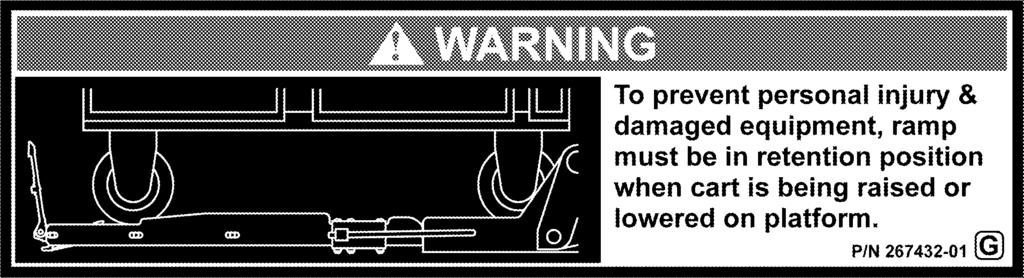
28 LOADING OR UNLOADING PLATFORM!! WARNING To prevent personal injury & damaged equipment, ramp must be in retention position when cart is being raised or lowered on platform. CAUTION To prevent injuries caused by tripping and falling, make sure retention ramps are in the ramp position before walking on and off outboard end of platform. NOTE: To unhook the retention ramp, stand at the RH side of fl ipover. After the retention ramp is unhooked, the recommended place for handling the retention ramp is at the center of the free edge (FIG. 28-2). 1. Unhook retention ramp (FIG. 28-1). To release from the catches, pull retention ramp toward outboard end of fl ipover as shown in FIG HOOK (LIFT HERE) PULL RETENTION RAMP UNHOOKING RETENTION RAMP (RH VIEW OF FLIPOVER) FIG CATCH (2 PLACES) RETENTION RAMP PULL HERE FLIPOVER RELEASING RETENTION RAMP (TOP VIEW OF FLIPOVER) FIG
29 LOADING OR UNLOADING PLATFORM - Cont d.! CAUTION To prevent injuries, stay clear of the retention ramp path as it is moved to ramp position. Go to either side of the ramp and stay out of the way. 2. Continue to pull retention ramp to the retention position (FIG. 29-1) and then to ramp position (FIG. 29-2). RETENTION PULL MOVING TO RETENTION POSITION (RH VIEW OF FLIPOVER) FIG. 29-1! RAMP MOVING TO RAMP POSITION (RH VIEW OF FLIPOVER) FIG WARNINGS A load should never extend past the edges of the platform. Do not place unstable loads on platform and do not allow load to exceed the lifting capacity of the Liftgate. If standing on platform, do not allow your feet to extend beyond the inboard edge of the platform. 3. Load the platform at ground level as follows. Make sure retention ramps are in the ramp position (FIG. 29-3). Next, move carts on the platform as shown in FIG If platform is equipped with cart dishes, ensure the rear wheels of each cart are seated in the dishes. RETENTION RAMPS LOADING PLATFORM AT GROUND LEVEL (RAMP POSITION) FIG
30 4. When carts are on the platform, place the retention ramps in the retention position (FIG. 30-1). Then, stand in the footprint area shown in FIG RETENTION ROTATING TO RETENTION POSITION (RH VIEW OF FLIPOVER) FIG RETENTION RAMPS LOADED PLATFORM FIG
31 LOADING OR UNLOADING PLATFORM - Cont d. NOTE: If necessary, release the toggle switch to stop the platform from moving. 5. Raise the platform to bed level as follows. Hold the internal toggle switch in the UP position (FIG. 31-1B) until the platform reaches bed level (FIG. 31-2). INTERNAL TOGGLE SWITCH FIG. 31-1B INTERNAL TOGGLE SWITCH FIG. 31-1A 6. Move carts from the platform to inside the vehicle body (FIG. 31-2). VEHICLE BODY PLATFORM RAISED TO BED LEVEL FIG
32 Pulling the load from vehicle to platform can result in a fall from platform and serious injury. When unloading vehicle, always push the load out on the platform. 7. Load the platform at bed level as follows. Make sure retention ramps are in the retention position (FIG. 32-1). Then, push carts out of the vehicle body to correct position on the platform. If platform is equipped with cart dishes, ensure the rear wheels of each cart are seated in the dishes. If standing on platform with the carts, stand in the footprint area shown and comply with WARNING on page 28.! WARNING RETENTION RAMPS VEHICLE BODY LOADING PLATFORM AT BED LEVEL (RAMP IN RETENTION POSITION) FIG NOTE: If necessary, release the toggle switch to stop the platform from moving. 8. Lower the platform to ground level as follows. Hold the internal toggle switch in the DOWN position (FIG. 32-2) until platform is sitting on the ground (FIG. 32-3). FIG PLATFORM ON THE GROUND FIG
33 LOADING OR UNLOADING PLATFORM - Cont d. 9. Unload the platform at ground level as follows. Reposition retention ramps to the ramp position (FIG. 33-1). Then, move cart off the platform as shown in FIG RAMP ROTATING TO RAMP POSITION (RH VIEW OF FLIPOVER) FIG RETENTION RAMPS UNLOADING PLATFORM AT GROUND LEVEL (RAMP POSITION) FIG
.")
 FIG.")
34 10. To stow ramps, rotate each retention ramp to the fl at position as shown in FIG Push the retention ramps fully into the catches (FIG. 34-2). Then, make sure retention ramps are hooked to the fl ipover (FIG. 34-3). STOWED ROTATING RAMP TO STOWED POSITION (RH VIEW OF FLIPOVER) FIG CATCH RETENTION RAMP FLIPOVER STOWING THE RAMPS (TOP VIEW OF FLIPOVER) FIG HOOK RETENTION RAMP RAMP HOOKED TO FLIPOVER (RH VIEW OF FLIPOVER) FIG
35
36
M REV. J APRIL 2012 OPERATION MANUAL GPTLR-25, GPTLR-33, GPTLR-44 & GPTLR-55
 M-04-05 REV. J APRIL 2012 OPERATION MANUAL GPTLR-25, GPTLR-33, GPTLR-44 & GPTLR-55 MAXON Lift Corp. 2012 TABLE OF CONTENTS WARNINGS...4 LIFTGATE TERMINOLOGY...5 RECOMMENDED DAILY OPERATION CHECKS...6
M REV. E JUNE 2009 OPERATION MANUAL GPTLR-25, GPTLR-33, GPTLR-44 & GPTLR-55
 M-04-05 REV. E JUNE 2009 OPERATION MANUAL GPTLR-25, GPTLR-33, GPTLR-44 & GPTLR-55 MAXON Lift Corp. 2009 TABLE OF CONTENTS WARNINGS...4 LIFTGATE TERMINOLOGY...5 RECOMMENDED DAILY OPERATION CHECKS...6 DECALS...8
OPERATION MANUAL RA-35 & RA-45
 M-13-02 REV. A NOVEMBER 2015 OPERATION MANUAL RA-35 & RA-45 To fi nd maintenance & parts information for your RA Liftgate, go to www.maxonlift.com. Click the PRODUCTS, SLIDELIFT & RA buttons. Open the
M REV. D AUGUST 2010 OPERATION MANUAL GPT-25, GPT-3, GPT-4, GPT-5, & GPTWR-3
 M-08-34 REV. D AUGUST 2010 OPERATION MANUAL GPT-25, GPT-3, GPT-4, GPT-5, & GPTWR-3 MAXON Lift Corp. 2010 TABLE OF CONTENTS LIFTGATE TERMINOLOGY... 5 RECOMMENDED DAILY OPERATION CHECKS... 6 DECALS (GPT
PRODUCT DOCUMENTATION PARTS PORTAL
 M-16-25 JULY 2017 To find maintenance & parts information for your GPTLR Liftgate, go to www. maxonlift.com. Click the PRODUCTS, TUK-A-WAY & GPTLR buttons. Open the Maintenance Manual in the PRODUCT DOCUMENTATION
M REV. H JUNE 2015 OPERATION MANUAL MTB-25 & MTB-30
 M-00-40 REV. H JUNE 2015 OPERATION MANUAL MTB-25 & MTB-30 To find maintenance & parts information for your MTB-25 & MTB-30 Liftgate, go to www. maxonlift.com. Click the PRODUCTS, MTB- 25 & MTB-30 buttons.
TKL-25 OPERATION MANUAL
 TKL-25 OPERATION MANUAL M-98-09 REV. C FEBRUARY 2004 KEEP THIS MANUAL IN CAB OF VEHICLE For a free copy of other manuals that pertain to this Liftgate, please visit our website at www.maxonlift.com or
OPERATION MANUAL. Me2-Series C LB CAPACITY C LB CAPACITY C LB CAPACITY
 M-14-36 AUGUST 2015 OPERATION MANUAL Me2-Series C2 1300 LB CAPACITY C2 1500 LB CAPACITY C2 1600 LB CAPACITY LIFT CORP. To fi nd maintenance & parts information for your Me2 Liftgate, go to www.maxonlift.com.
M REV. M SEPTEMBER 2013
 M-00-25 REV. M SEPTEMBER 2013 Operation Manual Contains: Warnings Decal & Plate Locations Standard Control Locations Liftgate & Retention Ramp Operation MAXON Lift Corp. 2013 KEEP THIS MANUAL IN CAB OF
INSTALLATION MANUAL RA-35 & RA-45 M REV. D SEPTEMBER 2017
 M-13-01 REV. D SEPTEMBER 2017 INSTALLATION MANUAL RA-35 & RA-45 To fi nd maintenance and parts information for your RA Liftgate, go to www.maxonlift.com. Click the PRODUCTS, SLIDELIFT & RA buttons. Open
M REV. A AUGUST 2008 OPERATION & MAINTENANCE MANUAL
 M-06-35 REV. A AUGUST 2008 OPERATION & MAINTENANCE MANUAL MAXON Lift Corp. 2008 TABLE OF CONTENTS OPERATION... 4 WARNINGS... 5 LIFTGATE TERMINOLOGY... 6 RECOMMENDED DAILY OPERATION CHECKS... 7 DECALS...
M REV. B JANUARY 2013 OPERATION & MAINTENANCE MANUAL
 M-06-35 REV. B JANUARY 2013 OPERATION & MAINTENANCE MANUAL MAXON Lift Corp. 2013 TABLE OF CONTENTS OPERATION... 4 WARNINGS... 5 LIFTGATE TERMINOLOGY... 6 RECOMMENDED DAILY OPERATION CHECKS... 7 DECALS...
GPT-25LM GPT-3LM GPT-4LM GPT-5LM
 M-97-16 REV. 5 APR. 2000 OPERATION MANUAL GPT-25LM GPT-3LM GPT-4LM GPT-5LM 11921 Slauson Avenue. Santa Fe Springs, CA. 90670 (800) 227-4116 C MAXON Lift Corp. 1997 LIFT CORP. 11921 Slauson Ave. Santa Fe
M AUGUST 2018 MAXON
 M-16-40 AUGUST 2018 MAXON Lift Corp. 2018 LIFT CORP. 11921 Slauson Ave. Santa Fe Springs, CA. 90670 CUSTOMER SERVICE: TELEPHONE (562) 464-0099 TOLL FREE (800) 227-4116 FAX: (888) 771-7713 NOTE: For latest
M REV. D APRIL 2008 MAINTENANCE MANUAL GPTLR-25, GPTLR-33, GPTLR-44, & GPTLR-55
 M-04-04 REV. D APRIL 2008 MAINTENANCE MANUAL GPTLR-25, GPTLR-33, GPTLR-44, & GPTLR-55 MAXON Lift Corp. 2008 LIFT CORP. LIFTGATE WARRANTY 11921 Slauson Ave. Santa Fe Springs, CA. 90670 CUSTOMER SERVICE:
M REV. A APRIL 2008 INSTALLATION MANUAL
 M-06-14 REV. A APRIL 2008 INSTALLATION MANUAL MAXON Lift Corp. 2008 TABLE OF CONTENTS WARNINGS... 3 STANDARD LIFTGATE COMPONENTS... 4 GPTWR-3 SERIES INSTALLATION PARTS BAGS... 5 VEHICLE REQUIREMENTS...
M REV. F AUGUST 2014 INSTALLATION MANUAL
 M-06-02 REV. F AUGUST 2014 INSTALLATION MANUAL MAXON Lift Corp. 2014 TABLE OF CONTENTS SUMMARY OF CHANGES: M-06-02, REVISION F... 4 SAFETY INSTRUCTIONS... 5 WARNINGS... 5 MM-1300 LIFTGATE COMPONENTS...
INSTALLATION INSTRUCTIONS
 INSTALLATION INSTRUCTIONS FOR WHEELCHAIR LIFT MODEL NO. WL7-vers. B DOT-Public Use Lift PATENTS PENDING MAXON Lift Corp. 2006 MP-06-01 REV. B AUGUST 2006 PATENTS PENDING TABLE OF CONTENTS INTRODUCTION...4
TE-20 & INSTALLATION MANUAL M REV. F SEPTEMBER 2015
 M-12-04 REV. F SEPTEMBER 2015 INSTALLATION MANUAL TE-20 & 72-150 To find maintenance & parts information for your TE-20 & 72-150 Liftgate, go to www.maxonlift.com. Click the PRODUCTS, TUK-A-WAY and TE-20
M OCTOBER 2017 MAXON
 M-17-08 OCTOBER 2017 MAXON Lift Corp. 2017 LIFT CORP. 11921 Slauson Ave. Santa Fe Springs, CA. 90670 CUSTOMER SERVICE: TELEPHONE (562) 464-0099 TOLL FREE (800) 227-4116 FAX: (888) 771-7713 NOTE: For latest
INSTALLATION MANUAL DMD-22 & DMD-33
 M-12-20 REV. E JULY 2016 INSTALLATION MANUAL DMD-22 & DMD-33 To fi nd maintenance & parts information for your DMD Liftgate, go to www.maxonlift. com. Click the PRODUCTS, RAILIFT & DMD buttons. Open the
M REV. D APRIL 2008 INSTALLATION MANUAL GPTLR-25, GPTLR-33, GPTLR-44, & GPTLR-55
 M-04-06 REV. D APRIL 2008 INSTALLATION MANUAL GPTLR-25, GPTLR-33, GPTLR-44, & GPTLR-55 MAXON Lift Corp. 2008 TABLE OF CONTENTS GPTLR LIFTGATE COMPONENTS... 5 GPTLR-SERIES INSTALLATION PARTS BOX... 6 VEHICLE
2017 MAXON LIFT CORP. M REV B NOVEMBER 2017
 2017 MAXON LIFT CORP. M-16-35 REV B NOVEMBER 2017 LIFT CORP. 11921 Slauson Ave. Santa Fe Springs, CA. 90670 CUSTOMER SERVICE: TELEPHONE (562) 464-0099 TOLL FREE (800) 227-4116 FAX: (888) 771-7713 NOTE:
M REV. C AUGUST 2008
 M-01-22 REV. C AUGUST 2008 Installation Manual Contains: Warnings Requirements - Body Strength & Installed Liftgate Liftgate Installation Components Liftgate Component Installation Instructions Hydraulic
M SEPTEMBER 2017
 M-17-33 SEPTEMBER 2017 To fi nd maintenance & parts information for your TE-15 or TE-20 Liftgate, go to www. maxonlift.com. Click the PRODUCTS, TUK-A-WAY and TE-15/TE-20 buttons. Open the Maintenance Manual
M REV. J JUNE 2014 MAINTENANCE MANUAL GPTLR-25, GPTLR-33, GPTLR-44, & GPTLR-55
 M-04-04 REV. J JUNE 2014 MAINTENANCE MANUAL GPTLR-25, GPTLR-33, GPTLR-44, & GPTLR-55 MAXON Lift Corp. 2014 LIFT CORP. LIFTGATE WARRANTY 11921 Slauson Ave. Santa Fe Springs, CA. 90670 CUSTOMER SERVICE:
INSTALLATION MANUAL TE-33, TE-33L & TEWR-33 M REV. K DECEMBER 2016
 M-11-06 REV. K DECEMBER 2016 INSTALLATION MANUAL TE-33, TE-33L & TEWR-33 To fi nd maintenance information for your TE-33 Liftgate, go to www.maxonlift.com. Click the PRODUCTS, TUK-A-WAY & TE-33 buttons.
M REV. D JANUARY 2003
 M-97-28 REV. D JANUARY 2003 LIFT CORP. 11921 Slauson Ave. Santa Fe Springs, CA. 90670 CUSTOMER SERVICE: TELEPHONE (562) 464-0099 TOLL FREE (800) 227-4116 FAX: (888) 771-7713 NOTE: For latest version Manuals
M REV B SEPTEMBER 2017
 M-16-33 REV B SEPTEMBER 2017 To fi nd maintenance & parts information for your TE-25 or TE-30 Liftgate, go to www. maxonlift.com. Click the PRODUCTS, TUK-A-WAY and TE-25/TE-30 buttons. Open the Maintenance
M APRIL 2012 INSTALLATION MANUAL DMD-22 & DMD-33
 M-11-13 APRIL 2012 INSTALLATION MANUAL DMD-22 & DMD-33 MAXON Lift Corp. 2012 TABLE OF CONTENTS WARNINGS... 3 NOTICE... 4 VEHICLE REQUIREMENTS... 5 BODY STRENGTH... 5 INSTALLED LIFTGATE... 7 LIFTGATE INSTALLATION
M REV. E APRIL 2011 MAINTENANCE MANUAL 2011 MAXON LIFT CORP.
 M-05-13 REV. E APRIL 2011 MAINTENANCE MANUAL 2011 MAXON LIFT CORP. LIFT CORP. 11921 Slauson Ave. Santa Fe Springs, CA. 90670 CUSTOMER SERVICE: TELEPHONE (562) 464-0099 TOLL FREE (800) 227-4116 FAX: (888)
INSTALLATION INSTRUCTIONS FOR WHEELCHAIR LIFT MODEL NO. WL7-vers. C WL7-vers. C-1K
 INSTALLATION INSTRUCTIONS FOR WHEELCHAIR LIFT MODEL NO. WL7-vers. C WL7-vers. C-1K DOT-Public Use Lift PATENTS PENDING FOR INSIDE VEHICLE INSTALLATION ONLY MAXON Lift Corp. 2011 MP-11-01 JULY 2011 PATENTS
M REV. G JANUARY 2003
 M-97-15 REV. G JANUARY 2003 LIFT CORP. 11921 Slauson Ave. Santa Fe Springs, CA. 90670 CUSTOMER SERVICE: TELEPHONE (562) 464-0099 TOLL FREE (800) 227-4116 FAX: (888) 771-7713 NOTE: For latest version Manuals
M REV. B AUGUST 2010 INSTALLATION MANUAL GPTWR-3
 M-08-36 REV. B AUGUST 2010 INSTALLATION MANUAL GPTWR-3 MAXON Lift Corp. 2010 TABLE OF CONTENTS WARNINGS... 3 SAFETY INSTRUCTIONS... 3 STANDARD LIFTGATE COMPONENTS... 4 GPTWR-3 INSTALLATION PARTS BAGS...
M REV. L AUGUST 2012
 M-00-24 REV. L AUGUST 2012 Installation Manual Contains: Warnings Requirements - Body Strength & Installed Liftgate Liftgate Installation Components Liftgate Component Installation Instructions Hydraulic
M JUNE 2008 MAINTENANCE MANUAL GPT-25, GPT-3, GPT-4 & GPT-5
 M-08-04 JUNE 2008 MAINTENANCE MANUAL GPT-25, GPT-3, GPT-4 & GPT-5 MAXON Lift Corp. 2008 LIFT CORP. 11921 Slauson Ave. Santa Fe Springs, CA. 90670 CUSTOMER SERVICE: TELEPHONE (562) 464-0099 TOLL FREE (800)
PRODUCT DOCUMENTATION PARTS PORTAL RAILIFT & DMD MAXON
 M-16-38 JUNE 2018 To fi nd maintenance & parts information for your DMD Liftgate, go to www.maxonlift. com. Click the PRODUCTS, RAILIFT & DMD buttons. Open the Maintenance Manual in the PRODUCT DOCUMENTATION
M REV. B APRIL 2008 MAINTENANCE MANUAL GPT-25, GPT-3, GPT-4 & GPT-5
 M-06-10 REV. B APRIL 2008 MAINTENANCE MANUAL GPT-25, GPT-3, GPT-4 & GPT-5 MAXON Lift Corp. 2008 LIFT CORP. 11921 Slauson Ave. Santa Fe Springs, CA. 90670 CUSTOMER SERVICE: TELEPHONE (562) 464-0099 TOLL
MAINTENANCE MANUAL RCM-1250C RCM-1250C AB RCM-1600C RCM-1600C AB Slauson Avenue Santa Fe Springs, CA (800)
") M-91-18 REV. F DECEMBER 2012 MAINTENANCE MANUAL RCM-1250C RCM-1250C AB RCM-1600C RCM-1600C AB LIFT CORP. 11921 Slauson Avenue Santa Fe Springs, CA 90607 (800) 227-4116 MAXON Lift Corp. 2012 LIFT CORP.
M-91-18 REV. F DECEMBER 2012 MAINTENANCE MANUAL RCM-1250C RCM-1250C AB RCM-1600C RCM-1600C AB LIFT CORP. 11921 Slauson Avenue Santa Fe Springs, CA 90607 (800) 227-4116 MAXON Lift Corp. 2012 LIFT CORP.
M JULY 2017 GPTLR Liftgate www. maxonlift.com PRODUCTS, TUK-A-WAY GPTLR Maintenance Manual PRODUCT DOCUMENTATION PARTS PORTAL TUK-A-WAY GPTLR
 M-16-24 JULY 2017 To find maintenance information for your GPTLR Liftgate, go to www. maxonlift.com. Click the PRODUCTS, TUK-A-WAY & GPTLR buttons. Open the Maintenance Manual in the PRODUCT DOCUMENTATION
M REV. A FEBURARY 2005 MAINTENANCE MANUAL GPTLR-25 & GPTLR-33
 M-0-0 REV. A FEBURARY 2005 MAINTENANCE MANUAL GPTLR-25 & GPTLR-33 LIFT CORP. 11921 Slauson Ave. Santa Fe Springs, CA. 90670 CUSTOMER SERVICE: TELEPHONE (562) 6-0099 TOLL FREE (800) 227-116 FAX: (888)
INSTRUCTION, GPTLR POWER DOWN HAND PUMP KIT
 LIFT CORPORATION Sht. 1 of 29 DSG# M-09-18 Rev. ~ Date: 03/05/14 INSTRUCTION, GPTLR POWER DOWN HAND PUMP KIT GPTLR KIT P/N 283332-01 HAND PUMP MOUNT BRACKET P/N 282381-01 QTY. 1 HAND PUMP HANDLE MOUNT
INSTRUCTION, GPT HAND PUMP KIT INSTALLATION GPT KIT P/N
 LIFT CORPORATION Sht. 1 of 28 DSG# M-09-16 Rev. B Date: 4/22/2014 INSTRUCTION, GPT HAND PUMP KIT INSTALLATION GPT KIT P/N 283330-01 NEEDLE VALVE, ADJUSTABLE, SAE #6 P/N 906739-01 QTY. 1 CONNECTOR, SAE
INSTRUCTIONS, C2 TORSION SPRING REPLACEMENT
 LIFT CORPORATION Sht. 1 of 9 DSG# M-14-47 Rev. - Date: 05/31/16 INSTRUCTIONS, C2 TORSION SPRING REPLACEMENT C2 (27 ) TORSION SPRING PIN KIT, P/N 295446-01 (1220) C2-92 TORSION SPRING KIT, P/N 295487-01
MAINTENANCE MANUAL FOR WHEELCHAIR LIFT MODEL NO. WL7A
 MAINTENANCE MANUAL FOR WHEELCHAIR LIFT MODEL NO. WL7A DOT-Public Use Lift PATENTS PENDING MAXON Lift Corp. 2005 MP-05-12 REV. A DECEMBER 2005 PATENTS PENDING LIFT CORP. 11921 Slauson Ave. Santa Fe Springs,
INSTRUCTIONS, FLASHING LIGHT INSTALLATION KIT
 LIFT CORPORATION Sht. 1 of 9 DSG# M-13-06 Rev. A Date: 03/10/14 INSTRUCTIONS, FLASHING LIGHT INSTALLATION KIT KIT P/N 286755-01 (BMRSD WITH ALUMINUM FLIPOVER & FIXED RAMP) LOCK WASHER, 1/4 P/N 902011-2
M-90-1 REV. F SEPTEMBER 2010 INSTALLATION MANUAL RC-2B RC-3B RC-4B RC-5B RC-6B RC-6K
 M-90-1 REV. F SEPTEMBER 2010 INSTALLATION MANUAL RC-2B RC-3B RC-4B RC-5B RC-6B RC-6K 11921 Slauson Avenue. Santa Fe Springs, CA. 90670 (800) 227-4116 MAXON Lift Corp. 2010 TABLE OF CONTENTS WARNINGS...
M REV. J JULY 2008 MAINTENANCE MANUAL RC-2B RC-3B RC-4B RC-5B RC-6B RC-6K
 M-90-03 REV. J JULY 2008 MAINTENANCE MANUAL RC-2B RC-3B RC-4B RC-5B RC-6B RC-6K 11921 Slauson Avenue. Santa Fe Springs, CA. 90670 (800) 227-4116 MAXON Lift Corp. 2008 LIFT CORP. 11921 Slauson Ave. Santa
INSTALLATION MANUAL M REV. G AUGUST 2016
 M-09-24 REV. G AUGUST 2016 INSTALLATION MANUAL To fi nd maintenance & parts information for your GPC Liftgate, go to www.maxonlift.com. Click the PRODUCTS, CONVENTIONAL & GPC buttons. Open the Maintenance
M REV. M SEPTEMBER 2013
 M-00-26 REV. M SEPTEMBER 2013 Maintenance Manual Contains: Warranty Information Warnings Service Time Chart Periodic Maintenance Checklist Service and Maintenance Instructions Decals Hydraulic & Electrical
M MARCH 2002 Parts Manual Contains:
 M-0- MARCH 00 Parts Manual Contains: Warranty Information Warnings Parts Ordering Information Exploded View Parts Breakdowns LIFT CORP. 9 Slauson Ave. Santa Fe Springs, CA. 900 CUSTOMER SERVICE: TELEPHONE
M REV. B FEBRUARY 2016
 M-14-21 REV. B FEBRUARY 2016 Installation Manual Contains: Warnings & Safety Instructions Requirements - Body Strength & Installed Liftgate Liftgate Installation Components Liftgate Component Installation
Assembly & Operator s Manual
 Assembly & Operator s Manual LiftGator XTR 1200lbs Removable Liftgate TM Visit our website at: www.liftgator.com WARNING: Read the entirety of this manual before using the LiftGator. Failure to do so can
RCM-1250 C RCM-1250 C AB RCM-1600 RCM-1600 C AB
 M-91-17 REV. E AUGUST 2012 INSTALLATION MANUAL RCM-1250 C RCM-1250 C AB RCM-1600 RCM-1600 C AB LIFT CORP. 11921 Slauson Avenue Santa Fe Springs, CA 90607 (800) 227-4116 MAXON Lift Corp. 2012 TABLE OF CONTENTS
72-25(B & LM) 72-30(B & LM)
 72-30(B & LM)") M-95-09 REV. C MARCH 1999 MAINTENANCE MANUAL LIFTGATE SERIES 72-25(B & LM) 72-30(B & LM) LIFT CORP. 11921 Slauson Avenue. Santa Fe Springs, CA. 90670 (800) 227-4116 C MAXON Lift Corp. 1999 LIFT CORP. 11921
M-95-09 REV. C MARCH 1999 MAINTENANCE MANUAL LIFTGATE SERIES 72-25(B & LM) 72-30(B & LM) LIFT CORP. 11921 Slauson Avenue. Santa Fe Springs, CA. 90670 (800) 227-4116 C MAXON Lift Corp. 1999 LIFT CORP. 11921
M OCTOBER 2016
 M-16-12 OCTOBER 2016 Maintenance Manual Contains: Warranty Information Warnings Service Time Chart Periodic Maintenance Checklist Service and Maintenance Instructions Decals Hydraulic & Electrical System
M APRIL 2000 INSTALLATION MANUAL MM Slauson Avenue. Santa Fe Springs, CA (800) LIFT CORP.
 LIFT CORP.") M-00-33 APRIL 2000 INSTALLATION MANUAL MM-1650 LIFT CORP. 11921 Slauson Avenue. Santa Fe Springs, CA. 90670 (800) 227-4116 C MAXON Lift Corp. 2000 LIFT CORP. CUSTOMER SERVICE: (562) 464-0099 (800) 227-4116
M-00-33 APRIL 2000 INSTALLATION MANUAL MM-1650 LIFT CORP. 11921 Slauson Avenue. Santa Fe Springs, CA. 90670 (800) 227-4116 C MAXON Lift Corp. 2000 LIFT CORP. CUSTOMER SERVICE: (562) 464-0099 (800) 227-4116
Owner s Manual PTN 1250 lb. and 1600 lb. Capacity Rail Liftgate
 www.waltco.com Phone: 800.211.3074 sales@waltco.com Fax: 800.211.3075 Owner s Manual PTN 1250 lb. and 1600 lb. Capacity Rail Liftgate Last Change GR02910 Date Page(s) Description 3-2017 10, 14, 18 P10
M REV. H OCTOBER 2005
 M-97-5 REV. H OCTOBER 2005 MAXON Lift Corp. 2005 LIFT CORP. 92 Slauson Ave. Santa Fe Springs, CA. 90670 CUSTOMER SERVICE: TELEPHONE (562) 464-0099 TOLL FREE (800) 227-46 FAX: (888) 77-773 NOTE: For latest
M REV. C AUGUST 2017
 M-16-10 REV. C AUGUST 2017 Installation Manual Contains: Warnings & Safety Instructions Requirements - Body Strength & Installed Liftgate Liftgate Installation Components Liftgate Component Installation
INSTRUCTION, GPT HOSE RETROFIT KIT
 LIFT CORPORATION Sht. 1 of 11 DSG# M-09-20 Rev. ~ Date: 10/14/09 INSTRUCTION, GPT HOSE RETROFIT KIT GPT Kit P/N 283358-01 HP HOSE, 3/8 I.D. X 82 LG, SAE #8 FACE SEAL O-RING P/N 283357-01 HP HOSE, 3/8 I.D.
INSTRUCTION, LVTS KIT, GPTLR KIT P/N
 LIFT CORPORATION Sht. 1 of 17 DSG# M-11-27 Rev. - Date: 07/03/12 INSTRUCTION, LVTS KIT, GPTLR KIT P/N 282326-01 LOW VOLTAGE THERMAL SWITCH (LVTS MODULE) P/N 906530-01 QTY. 1 LOW VOLTAGE THERMAL SWITCH
Parts Manual Contains:
 Parts Manual Contains: M-0- REV. B JANUARY 009 Warranty Information Warnings Parts Ordering Information Exploded View Parts Breakdowns MAXON Lift Corp. 009 LIFT CORP. 9 Slauson Ave. Santa Fe Springs,
INSTRUCTIONS (DROP PIN KIT FOR REPLACEMENT CABLE)
") LIFT CORPORATION Sht. 1 of 6 DSG# M-14-48 Rev. - Date: 06/15/16 INSTRUCTIONS (DROP PIN KIT FOR REPLACEMENT ) C1 DROP PIN ASSEMBLY, P/N 295507-01 (10512) RETAINING RING 5/8 DIA. P/N 905004-07 PIN WELDMENT
LIFT CORPORATION Sht. 1 of 6 DSG# M-14-48 Rev. - Date: 06/15/16 INSTRUCTIONS (DROP PIN KIT FOR REPLACEMENT ) C1 DROP PIN ASSEMBLY, P/N 295507-01 (10512) RETAINING RING 5/8 DIA. P/N 905004-07 PIN WELDMENT
M REV. K SEPTEMBER Parts Manual Contains: Warranty Information Warnings Parts Ordering Information Exploded View Parts Breakdowns
 M-07- REV. K SEPTEMBER 03 Parts Manual Contains: Warranty Information Warnings Parts Ordering Information Exploded View Parts Breakdowns MAXON Lift Corp. 03 LIFT CORP. 9 Slauson Ave. Santa Fe Springs,
M REV. D DECEMBER Parts Manual Contains: Warranty Information Warnings Parts Ordering Information Exploded View Parts Breakdowns
 M-07- REV. D DECEMBER 009 Parts Manual Contains: Warranty Information Warnings Parts Ordering Information Exploded View Parts Breakdowns MAXON Lift Corp. 009 LIFT CORP. 9 Slauson Ave. Santa Fe Springs,
Owner s Manual HLF 2500, 3000, 4000, & 5000 lb. Capacity Flipaway Liftgates
 www.waltco.com Phone: 800.211.3074 sales@waltco.com Fax: 800.211.3075 Owner s Manual HLF 2500, 3000, 4000, & 5000 lb. Capacity Flipaway Liftgates Last Change Date Page(s) Description 1-2013 10,12 & 16
INSTRUCTION, GPT HAND PUMP KIT (BUCHER PUMP) INSTALLATION
 INSTALLATION") LIFT CORPORATION Sht. 1 of 27 DSG# M-15-13 Rev. A Date: 11/04/15 INSTRUCTION, GPT HAND PUMP KIT (BUCHER PUMP) INSTALLATION KIT P/N 296075-01 NEEDLE VALVE, ADJUSTABLE, SAE #6 P/N 906739-01 QTY. 1 CONNECTOR,
LIFT CORPORATION Sht. 1 of 27 DSG# M-15-13 Rev. A Date: 11/04/15 INSTRUCTION, GPT HAND PUMP KIT (BUCHER PUMP) INSTALLATION KIT P/N 296075-01 NEEDLE VALVE, ADJUSTABLE, SAE #6 P/N 906739-01 QTY. 1 CONNECTOR,
INSTRUCTION, BMR AUXILIARY CONTROL
 LIFT CORPORATION Sht. 1 of 10 DSG# M-16-05 Rev. A Date: 01/16/17 INSTRUCTION, BMR AUXILIARY CONTROL GRAVITY DOWN CONTROL KIT, P/N 297080-11 POWER DOWN CONTROL KIT, P/N 297080-12 ELECTRICAL CONTROL TEE
M REV. A DECEMBER 2016
 M-16-10 REV. A DECEMBER 2016 Installation Manual Contains: Warnings & Safety Instructions Requirements - Body Strength & Installed Liftgate Liftgate Installation Components Liftgate Component Installation
K-SERIES PUBLIC USE LIFT OPERATING INSTRUCTIONS
 -PRINT- II. T K-SERIES PUBLIC USE LIFT OPERATING INSTRUCTIONS -TABLE OF CONTENTS- his chapter contains safety precautions, daily safety check instructions, control and indicator descriptions, and operating
INSTRUCTION, CURRENT GPT HOSE RETROFIT KIT
 LIFT CORPORATION Sht. 1 of 11 DSG# M-09-22 Rev. ~ Date: 01/22/10 INSTRUCTION, CURRENT GPT HOSE RETROFIT KIT Kit P/N 283372-01 (FOR GPT-25, GPT-3 & GPTWR-3) HP HOSE, 3/8 I.D. X 36 LG, SAE #6-6 FACE SEAL
INSTRUCTIONS, (FORD) SUPER DUTY INSTALLATION KIT (C2 PICKUP LIFTGATES)
 SUPER DUTY INSTALLATION KIT (C2 PICKUP LIFTGATES)") LIFT CORPORATION Sht. 1 of 20 DSG# M-14-32 Rev. B Date: 05/31/2017 INSTRUCTIONS, (FORD) SUPER DUTY INSTALLATION KIT (C2 PICKUP LIFTGATES) FORD SUPER DUTY F-250 PICKUP TRUCKS, 1999-2016 FORD SUPER DUTY
LIFT CORPORATION Sht. 1 of 20 DSG# M-14-32 Rev. B Date: 05/31/2017 INSTRUCTIONS, (FORD) SUPER DUTY INSTALLATION KIT (C2 PICKUP LIFTGATES) FORD SUPER DUTY F-250 PICKUP TRUCKS, 1999-2016 FORD SUPER DUTY
Important. Contents. Contact us:
 Operator's Manual First Edition Ninth Printing Important Read, understand and obey these safety rules and operating instructions before operating this machine. Only trained and authorized personnel shall
K-Series DOT Public Use Lift
 K-Series DOT Public Use Lift OPERATOR MANUAL 10/10/11 32DSSK05.C 2011 RICON CORPORATION All Rights Reserved U.S. and Foreign Patents Pending Printed in the United States of America This RICON product must
S-SERIES PUBLIC USE OPERATING INSTRUCTIONS
 -PRINT- II. T S-SERIES PUBLIC USE OPERATING INSTRUCTIONS -TABLE OF CONTENTS- his chapter contains safety precautions, daily safety check instructions, control and indicator descriptions and operating instructions
K-Series DOT Private Use Lift
 K-Series DOT Private Use Lift OPERATOR MANUAL -PRINT- 10/15/11 32DSSK03.C 2011 RICON CORPORATION All Rights Reserved U.S. and Foreign Patents Pending Printed in the United States of America -HOME- This
Owner s Manual EM25, EM33
 www.waltco.com Phone: 800.211.3074 sales@waltco.com Fax: 800.211.3075 Owner s Manual EM25, EM33 2500, 3300 lb. Capacity Flipaway Liftgates GR02693 Waltco Lift Corp. Waltco Lift Corp. Waltco Lift Inc. Corporate
Tailgates By THIEMAN WT20, 30 & 40 PLEASE READ AND UNDERSTAND THE CONTENTS OF THIS MANUAL BEFORE OPERATING THE EQUIPMENT. HIEMAN
 WEIGHTLIFTER Tailgates By THIEMAN WT20, 30 & 40 OWNERS MANUAL/PARTS LIST! IMPORTANT! KEEP IN VEHICLE! PLEASE READ AND UNDERSTAND THE CONTENTS OF THIS MANUAL BEFORE OPERATING THE EQUIPMENT. NATIONAL TRUCK
Important. Contents. Contact us:
 Operator's Manual Third Edition Third Printing Important Read, understand and obey these safety rules and operating instructions before operating this machine. Only trained and authorized personnel shall
M REV. F APR MAINTENANCE MANUAL GPT-3LM Slauson Avenue. Santa Fe Springs, CA (800)
") M-97-25 REV. F APR. 2000 MAINTENANCE MANUAL GPT-3LM 92 Slauson Avenue. Santa Fe Springs, CA. 90670 (800) 227-46 C MAXON Lift Corp. 2000 LIFT CORP. 92 Slauson Ave. Santa Fe Springs, CA. 90670 CUSTOMER SERVICE:
M-97-25 REV. F APR. 2000 MAINTENANCE MANUAL GPT-3LM 92 Slauson Avenue. Santa Fe Springs, CA. 90670 (800) 227-46 C MAXON Lift Corp. 2000 LIFT CORP. 92 Slauson Ave. Santa Fe Springs, CA. 90670 CUSTOMER SERVICE:
S-SERIES ADA TRANSIT USE OPERATING INSTRUCTIONS
 -PRINT- II. T S-SERIES ADA TRANSIT USE OPERATING INSTRUCTIONS -TABLE OF CONTENTS- his chapter contains safety precautions, daily safety check instructions, control and indicator descriptions, and operating
INSTRUCTION, BMR STREET-SIDE CONTROL
 LIFT CORPORATION Sht. 1 of 13 DSG# M-16-04 Rev. A Date: 01/13/17 INSTRUCTION, BMR STREET-SIDE CONTROL GRAVITY DOWN CONTROL KIT, P/N 297080-01 POWER DOWN CONTROL KIT, P/N 297080-02 ELECTRICAL CONTROL TEE
Owner s Manual C15, C20, C25
 www.waltco.com Phone: 800.211.3074 sales@waltco.com Fax: 800.211.3075 Owner s Manual C15, C20, C25 1600, 2000, 2500 lb. Capacity Flipaway Liftgates Waltco Lift Corp. Waltco Lift Corp. Waltco Lift Inc.
SL15/20-6 AND SL15/20-10
 STOWAWAY SIDELOADER Tailgates By THIEMAN SL15/20-6 AND SL15/20-10 OWNERS MANUAL/PARTS LIST! NATIONAL TRUCK EQUIPMENT ASSOCIATION Member IMPORTANT! KEEP IN VEHICLE! PLEASE READ AND UNDERSTAND THE CONTENTS
LIFT CORP. CUSTOMER SERVICE: (562) (800) FAX: (888) Slauson Ave. Santa Fe Springs, CA TECHNICAL SERVICE: (800)
 (800) FAX: (888) Slauson Ave. Santa Fe Springs, CA TECHNICAL SERVICE: (800)") M-90-1 REV. B JAN. 2000 INSTALLATION MANUAL RC-2B RC-3B RC-4B RC-5B RC-6B RC-6K 11921 Slauson Avenue. Santa Fe Springs, CA. 90670 (800) 227-4116 C MAXON Lift Corp. 1999 LIFT CORP. CUSTOMER SERVICE: (562)
M-90-1 REV. B JAN. 2000 INSTALLATION MANUAL RC-2B RC-3B RC-4B RC-5B RC-6B RC-6K 11921 Slauson Avenue. Santa Fe Springs, CA. 90670 (800) 227-4116 C MAXON Lift Corp. 1999 LIFT CORP. CUSTOMER SERVICE: (562)
Daily verifications : 1. Function and completeness of all operating and security equipment
 11921 Slauson Avenue. Santa Fe Springs, CA 90670 (800) 227-4116 General information You have decided to purchase a top Slidelift. The Maxon Slidelift is very easy to use and to maintain. It is equipped
Owner s Manual RGL and RBGL 2000 lb lb. Capacity Rail Liftgates
 www.waltco.com Phone: 800.211.3074 sales@waltco.com Fax: 800.211.3075 Owner s Manual RGL and RBGL 2000 lb. - 6000 lb. Capacity Rail Liftgates GR02479 Waltco Lift Corp. Waltco Lift Corp. Waltco Lift Inc.
S-Series Personal Use Lift
 S-Series Personal Use Lift -PRINT- Operator Manual 10/15/11 -HOME- 2011 RICON CORPORATION All Rights Reserved U.S. Patent Nos: 4,534,450; 5,308,215; 5,445,488; 5,605,431; 5,944,473 Australian Patent No:
Slidelift. Operator`s handbook GPS 44 X1 GPS 55 X1. Lift CORP Slauson Avenue. Santa Fe Springs, CA (800)
") Slidelift GPS 44 X1 GPS 55 X1 Lift CORP. 11921 Slauson Avenue. Santa Fe Springs, CA 90670 (800) 227-4116 Sörensen Hydraulik GmbH 28.03.2013 20 910 563 11921 Slauson Avenue. Santa Fe Springs, CA 90670
Slidelift GPS 44 X1 GPS 55 X1 Lift CORP. 11921 Slauson Avenue. Santa Fe Springs, CA 90670 (800) 227-4116 Sörensen Hydraulik GmbH 28.03.2013 20 910 563 11921 Slauson Avenue. Santa Fe Springs, CA 90670
INSTRUCTIONS, SLEEVED CABLE KITS BMRA (INCLUDES BMRA-CS) KIT P/N
 KIT P/N") LIFT CORPORATION Sht. 1 of 14 DSG# M-14-20 Rev. A Date: 11/29/2016 INSTRUCTIONS, SLEEVED KITS BMRA (INCLUDES BMRA-CS) KIT P/N 289857-100 HOSE & ASSEMBLY P/N 289857-01 QTY. 1 PLASTIC TIE, 7 LG P/N 205780
LIFT CORPORATION Sht. 1 of 14 DSG# M-14-20 Rev. A Date: 11/29/2016 INSTRUCTIONS, SLEEVED KITS BMRA (INCLUDES BMRA-CS) KIT P/N 289857-100 HOSE & ASSEMBLY P/N 289857-01 QTY. 1 PLASTIC TIE, 7 LG P/N 205780
IMPORTANT GT-33/44 WARNING. Owners Manual 3300 and 4400 lb. Capacity Sliding Liftgate KEEP IN VEHICLE. Visit us at
 GT-33/44 Visit us at www.waltco.com Owners Manual 3300 and 4400 lb. Capacity Sliding Liftgate IMPORTANT WARNING KEEP IN VEHICLE Improper operation and maintenance of this liftgate could result in severe
PARTS MANUAL. PLR 20S, 2000 lbs. Capacity PLR 25S, 2500 lbs. Capacity PLR 25D, 2500 lbs. Capacity PLR 33D, 3300 lbs.
 PARTS MANUAL PLR 20S, 2000 lbs. Capacity PLR 25S, 2500 lbs. Capacity PLR 25D, 2500 lbs. Capacity PLR 33D, 3300 lbs. Capacity 08/16 Document Part Number: 90-0316-004 / 16-695_90-00_00-04 ECN-M0863, Rev.
INSTRUCTIONS, RAM DUAL REAR WHEEL TRUCKS INSTALLATION KIT (C2 LIFTGATES)
") LIFT CORPORATION Sht. 1 of 23 DSG# M-15-25 Rev. B Date: 05/31/2017 INSTRUCTIONS, RAM DUAL REAR WHEEL TRUCKS INSTALLATION KIT (C2 LIFTGATES) RAM 3500 DUAL REAR WHEEL PICKUP TRUCKS, 2013 TO 2015 KIT P/N
LIFT CORPORATION Sht. 1 of 23 DSG# M-15-25 Rev. B Date: 05/31/2017 INSTRUCTIONS, RAM DUAL REAR WHEEL TRUCKS INSTALLATION KIT (C2 LIFTGATES) RAM 3500 DUAL REAR WHEEL PICKUP TRUCKS, 2013 TO 2015 KIT P/N
This chapter contains safety precautions, daily safety check instructions, control and indicator
 III. OPERATING INSTRUCTIONS This chapter contains safety precautions, daily safety check instructions, control and indicator descriptions and operating instructions for the RICON S-Series Export Use Wheelchair
ILM16 ILM20 ILM30 ILM12AF ILM16AF ILM20AF ILM30AF
 ILM Series Liftgates Read Before Installing INSTALLATION MANUAL For Models: ILM12 ILM16 ILM20 ILM30 ILM12AF ILM16AF ILM20AF ILM30AF Interlift, Inc. a Subsidary of MBB Liftsystems AG 15939 Pluma Avenue
OPERATOR S MANUAL 7(5 & ( 8&. $5.00 P/N REV.B
 OPERATOR S MANUAL &281 2817( 7(5 %$/$1&( /,)7 7758& 8&. $5.00 P/N 901345 REV.B As a lift truck operator, you are responsible for a machine that is useful, powerful, and can be hazardous if not operated
INSTRUCTIONS, NISSAN TITAN TRUCK INSTALLATION KIT (C2 PICKUP LIFTGATES)
") LIFT CORPORATION Sht. 1 of 18 DSG# M-14-33 Rev. A Date: 05/31/2017 INSTRUCTIONS, NISSAN TITAN TRUCK INSTALLATION KIT (C2 PICKUP LIFTGATES) NISSAN TITAN PICKUP TRUCKS, 2004-2015 KIT P/N 295040-01 MOUNTING
LIFT CORPORATION Sht. 1 of 18 DSG# M-14-33 Rev. A Date: 05/31/2017 INSTRUCTIONS, NISSAN TITAN TRUCK INSTALLATION KIT (C2 PICKUP LIFTGATES) NISSAN TITAN PICKUP TRUCKS, 2004-2015 KIT P/N 295040-01 MOUNTING
T6 Owners Manual. Basic Function
 T6 Owners Manual Basic Function The T6 is a frameless aluminum end dump trailer. It is used mainly for hauling sand, gravel and dirt. The material is discharged by extending the hoist which raises the
THE GLIDER 5th Wheel Attachment
 April 2007 APPLICATION: INSTALLATION INSTRUCTIONS MODEL NO. 70460 70046 THE GLIDER 5th Wheel Attachment For use on short bed pickup applications US Patent No. 6247720 COMPLETE PARTS LIST Part Description