PROJECT MERCURY F L I G H T M A N U A L
|
|
|
- Thomasina Flynn
- 5 years ago
- Views:
Transcription


1 F L I G H T M A N U A L
2 REENTRY AN ORBITAL SIMULATOR PROJECT MERCRUY DRAFT UPDATED: 09/29/ P a g e
3 TABLE OF CONTENTS I. INTRODUCTION ABOUT A BRIEF HISTORY MISSION PROFILES CONTROLS... 9 II. MAJOR COMPONENTS THE SPACECRAFT ATTITUDE CONTROL CABIN III. LAUNCH VEHICLES MERCURY-REDSTONE MERCURY-ATLAS IV. ENVIRONMENTAL CONTROL SYSTEM GENERAL OXYGEN COOLING CABIN PRESSURE OPERATION V. FLIGHT CONTROL SYSTEMS GENERAL ATTITUDE CONTROL FLIGHT MODES VI. RETROGRADE ROCKET SYSTEM GENERAL OPERATION RETROGRADE TIMING P a g e
4 VII. SEQUENCER GENERAL EVENTS VIII. ELECTRICAL SYSTEM GENERAL DC POWER AC POWER & INVERTERS LIGHTS FUSES IX. COMMUNICATION GENERAL OPERATION X. NAVIGATIONAL AIDS GENERAL THE PERISCOPE XI. REENTRY & LANDING RETROGRADE REENTRY LANDING XII, CHECKLISTS GENERAL CHECKLISTS Preflight checklist Abbreviated Preflight checklist Full internal power checklist Final check before launch Ascent Orbit Enter fly by wire Manual mode P a g e
5 Rate Command Before Retro Retrograde Reentry Landing P a g e

6 I. INTRODUCTION 5 P a g e
7 I. INTRODUCTION 1. ABOUT Project Mercury for REENTRY is one of the spacecrafts available for flight in the space simulator REENTRY by Wilhelmsen Studios. It comes with an easy to fly arcade version that enables you to simply fly the spacecraft from a 3 rd person perspective using simple controls, and a study level PRO version modelled after the real spacecraft. The goal of the PRO version of the spacecraft is to mimic it to the real spacecraft flown by real astronauts. The capsule is modelled after the Mercury Familiarization Manual SEDR 104 (5/20/1962) used by MA-7 (Carpenter) and MA-8 (Schirra) and contains most of the simple and advanced controls from all the different Mercury Capsule configurations, including the satellite clock, the Earth Path Indicator, the electrical system using 3 main fuel cells, two standby and one isolated and so on. The reason for this choice is that this configuration of the spacecraft got all the systems developed for Project Mercury and can fly all the real scenarios. All training needed to fly the capsule is available in this manual and in-game. If you want to study the spacecraft down to the lowest details, I highly recommended to read the manual by NASA. You can find the manual here: DOWNLOAD The game can be downloaded from - the Mercury Spacecraft is included in this package. JOIN THE CLUB Join the official Astronauts of Reentry club on the GameHub, accessible from the Windows Store page for the game! Share clips, screenshots and meet fellow players! WHAT IS THIS MANUAL? This manual contains most of the information you need to successfully master the Mercury Spacecraft in REENTRY. This manual is specific to the Mercury Spacecraft. For generic REENTRY information, please see the REENTRY User Manual. DONATE TO SUPPORT THE DEVELOPMENT OF THE GAME If you wish to support the development of this game, or if you enjoy playing it, please consider 6 P a g e
8 giving a small donation. Writing an application like this is a lot of fun and challenging, but also this takes up a lot of my spare time and my limited resources to fund it. Any donations will help me cover development costs, assets and asset creation, server hosting, coffee for staying up all night as well as motivation. You can donate from the Main Menu of the game, or online using PayPal on the following page: Want to get your name in the CREDITS screen of the game? I wish to thank everyone who supports the development if this game. If you did a donation, and wish to appear on the Credits screen of the game, please send me an to petriw@gmail.com with the donation details and what name you wish to use (your first name, full name, nickname (needs to be legal). From once space enthusiast to another, thank you again for considering giving a donation! LEGAL Images and information in the manual, as well as in the Project Mercury module for REENTRY is based on information released by NASA. Also, images and references from NASA is used. The images in this guide and game is using public domain images from NASA. The information described here is tailored to the simulation and my implementation of the spacecraft for REENTRY. Both public documents released by NASA and Wikipedia has been used as a reference in my implementation of Project Mercury, as well as writing the education material for the app, including this manual, in-game academy, and mission flow. 2. A BRIEF HISTORY Project Mercury was the first space program of the United States. It started in 1958, and completed in 1963 after six successful manned flights. It had three main objectives: 1) To orbit a manned spacecraft around Earth 2) To investigate man's ability to function in space 3) To recover both man and spacecraft safely 7 P a g e

9 During the last decade, technology had evolved to allow the long-awaited dream of reaching space. Project Mercury was born on October 7, 1958 and lasted for almost 5 years, ending with Coopers long duration mission where he orbited Earth 22 times. The six manned flights of Project Mercury provided a lot of research and knowledge on how both technology and humans react to being in the environment of space and zero gravity for long and short durations. The spaceship was a cone-shaped capsule with room for one pilot. The blunt end was covered with a heat shield to protect it during reentry, and the sharp end had sensors and antennas, as well as an escape tower. The escape tower was used to separate and take the capsule away from the launch vehicle during abort. The Mercury program used two launch vehicles: Redstone for suborbital missions and Atlas for orbital missions. The Mercury 7 was the team of the 7 astronauts who was in the Mercury Program. 3. MISSION PROFILES There are two different types of missions for Project Mercury. The first is a sub-orbital flight where the capsule visits space for a few minutes before reentering again, and the second is orbital mission where the spaceship orbits the Earth. Sub-Orbital mission Fig Sub-Orbital trajectory, NASA. 8 P a g e


10 Orbital mission The orbital mission profile is almost identical as the sub-orbital mission with exception of an additional booster stage during ascent, and the time the retrofire happens. The retrofire phase is usually hours into the flight. The ascent stage also takes a few extra minutes due to the increased velocity needed to enter orbital speed. 4. CONTROLS There are multiple controls you can interact with in the cockpit, as well as a joystick to orient the spacecraft. This section describes how you can use the mouse/keyboard to interact with these controls. Left click the protective cover to remove the cover. If the cover is removed and you want to put it back, right click the button and it will be placed back on. If you press the trigger after removing the cover, the button will be pressed and trigger will execute. The trigger button got a cover on it that needs to be removed before exposing the button. With the cover removed, a left click will execute the trigger. These operations are often irreversible, thus the need for a security cover. A switch can have two or three positions. Left, middle and right, or up, middle and down. Left click will move the switch leftwards, or upwards, while right clock will move it rightwards or downwards. Every fuse got one primary fuse and a secondary fuse for redundancy. A fuse switch can have three positions. Up is in position 1, middle is OFF and down being position 2. Position 1 is the primary fuse, and position 2 is the secondary fuse. 9 P a g e

.")


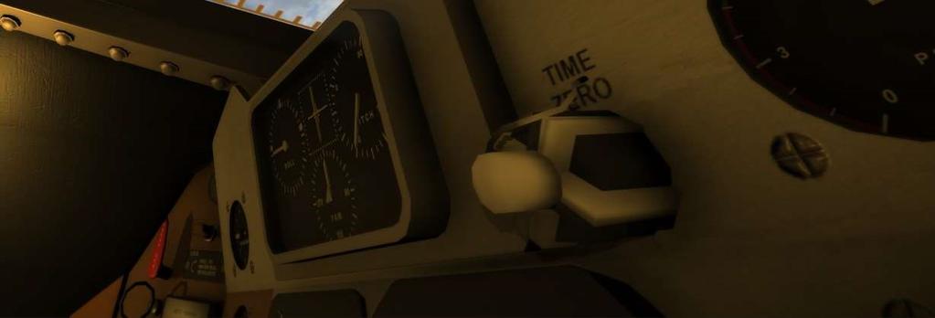
11 A knob can be moved to each selection. Right click moves the selection rightwards (counter-clockwise) and left click moves it leftwards (clockwise). A pull ring is a trigger system that can be pulled to activate the function. The pull/push handles got two positions, either in or out. Left mouse button pushes it in. Right mouse button pulls it out. The pull/push handles got two positions, either in or out. Left mouse button pushes it in. Right mouse button pulls it out. The time control works the same way as the rotator knob 10 P a g e


12 The ECS adjusters works the same way as the knobs The blood pressure buttons work the same way as a trigger buttons. Click once to activate it. They can be activated multiple times. ORIENTATION To orient that spacecraft, either a keyboard or a joystick can be used. W: Pitch down S: Pitch up A: Yaw left D: Yaw right Q: Roll left E: Roll right TOOLS T: Flashlight V: Show/Hide UI 11 P a g e


13 II. MAJOR COMPONENTS 12 P a g e
14 II. MAJOR COMPONENTS The capsule consists of a control panel where all fuses, switches and gauges are located. The capsule can contain one pilot who enter through a bolted hatch. The astronaut is seated in a compact cabin within reach of every switch and gauge needed for capsule orientation. A window just above the panel can be used to orient the spaceship based on the surroundings. The capsule got an antenna on the top, and a heat shield on the blunt side. Once the capsule is separated from the launch vehicle, it got no way of altering the orbit unless the RETRO engines are fired. The RETRO engines are attached to the capsule on the blunt side, just on top of the heat shield. Once the RETROs have fired, it is jettisoned from the capsule, exposing the heat shield for reentry. During ascent, an escape tower is attached on top of the launch vehicle. It is used to separate the capsule from the launch vehicle during launch emergencies. Once the capsule reach space, it is no longer needed and is jettisoned from the capsule. The capsule got one drogue for use when landing. It will correct the attitude of the capsule for landing, as well as decelerating the capsule for main parachute. The main parachute will jettison the antenna and the drogue and slow down the capsule for landing speed. It is attached until landing. A backup reserve chute is used if main chute fails. A landing bag just under the heat shield will pump up after main chute deploy to reduce shock to the structure and capsule during landing. 1. THE SPACECRAFT The Mercury Capsule is the spacecraft itself. A launch vehicle (the rocket) carries the capsule from the launch pad to space, where the launch vehicle is separated, and the capsule was continuing the journey on its own. The spacecraft is a cone shaped capsule attached to a launch vehicle, with a launch escape tower attached to the top of the capsule. It is mounted to the launch vehicle using an adapter. 13 P a g e
15 Fig Capsule, from the SEDR 104 user manual During launch and ascent, both the launch vehicle and the launch escape tower will be jettisoned/separated from the capsule, leaving only the capsule. The capsule proceeded with the mission objectives, and reenters back down through the atmosphere and splashes down in the ocean using drogues and parachutes to slow down after the atmospheric reentry. 14 P a g e
16 Fig The Mercury Capsule after stage separations and launch escape system jettison, SEDR 104 user manual The capsule is equipped with a retro engine used to slow down the capsule, so it can reenter safely, or get out from an orbit. An antenna module is jettisoned before the drogue is activated during reentry. This antenna is used for radio communication during the mission, and is attached on the sharp side of the capsule. During reentry, the drogue provides initial drag and attitude correction before the main chutes are activated. The blunt end of the capsule contains a heat shield used to protect the capsule from the high temperatures during atmospheric reentry, and a landing bag that is activated before splashdown to reduce the structural shock/impact of landing. 15 P a g e
17 Figure Major components of the capsule, SEDR 104 manual 2. ATTITUDE CONTROL The spacecraft can change attitude in flight using a set of attitude thrusters called the reaction control system (RCS). Using a control stick, or automated systems, the capsule can fire the correct thrusters to rotate and change attitude. 16 P a g e
18 Fig Attitude axes, from the SEDR 104 manual The normal flight direction is with the blunt end going forward, meaning that the retro engines is facing the prograde direction/flight direction. The reason for this is that in the case of an emergency, the retro engines could fire quickly and return to Earth. The reaction control system thrusters can change the attitude of the spacecraft in positive and negative Pitch, Yaw and Roll direction, giving full attitude range. 17 P a g e
19 3. CABIN The cabin consists of one chair for the astronaut, a window, a control panel with all the fuses, instruments and switches needed to operate the spacecraft, a hatch to enter and escape the spaceship, and various equipment lockers and so on. 18 P a g e


20 III. LAUNCH VEHICLES 19 P a g e

21 III. LAUNCH VEHICLES During Project Mercury, two different launch vehicles was used. Redstone was the first used Launch Vehicle, and was used in the two first manned spaceflights by the U.S. Using the Redstone LV, the spacecraft could enter a suborbital flight above the atmosphere of Earth. The second LV used during Project Mercury was the Atlas. The Atlas was more powerful than Redstone and could launch the Mercury Spacecraft into orbit around Earth. 1. MERCURY-REDSTONE The Mercury-Redstone Launch Vehicle (LV) was the first American manned space booster. The booster was 25.41m high and carried the spaceship on top of it, including the Launch Escape (the tower on top of the capsule) system. It was derived from the first stage of the U. S. Army s Redstone ballistic missile named Jupiter-C. It was modified to improve the safety and reliability requirements for human spaceflight. The U. S. Army s Redstone ballistic missile was chosen by NASA due to being the oldest one in the US fleet. It had been active since 1953 with many successful test flights. The Mercury-Redstone LV had one stage. It was based on a modified U. S. Army s Redstone ballistic missile stage named Jupiter-C due to its lengthened tanks to carry enough propellant to reach a suborbital trajectory. The designers of the Mercury-Redstone chose the Rocketdyne A-7 engine. The LV used one of these engines, producing 350 kn of thrust. It was fueled with a 75% ethyl alcohol and 25% water solution. This fuel was not as powerful as the what the Jupiter- C originally used, but it was less toxic in cases of emergencies. The fuel tank was pressurized using Nitrogen, so an additional nitrogen tank was placed above the fuel and liquid oxygen tanks. Figure shows the components of the booster. 20 P a g e


22 Fig Mercury-Redstone LV Structure, The Aft Unity housed the electronics, instrumentation equipment, guidance system and the adapter where the Mercury Capsule was attached to. When the booster had launched the capsule in a suborbital trajectory, it was separated from the capsule and the capsule would continue on its own. The Mercury-Redstone LV also had an automated in-flight abort sensing system. In the event of a catastrophic error, the launch escape system would fire its own little engines and pull the capsule away from the malfunctioning launch vehicle. The abort detection system was also a part of the aft section. Another section in the Aft unit is a ballast section. This section was there to prevent excess vibrations during launch. Fig shows a diagram with the booster with the capsule and the launch escape tower attached to it. This is the configuration that was flown on the Mercury- Redstone missions. The total burn time of the Launch Vehicle was seconds, enough to put the capsule in space. 21 P a g e

23 Fig 3.2 The Mercury-Redstone booster, 22 P a g e
24 2. MERCURY-ATLAS The Mercury-Atlas Launch Vehicle was much larger than Mercury-Redstone, and was capable of sending an astronaut into a low Earth orbit. The Mercury-Atlas was a member of the Atlas family of rockets, derived from the SM-65D Atlas missile, manufactured by Convair. It was 28.7 meters high. The choice for using Atlas was that it was the only launch vehicle in the US that could put a spacecraft into orbit, with many test flights. The LV had one and a half stages, with a total of 3 engines. All engines were ignited at lift-off. Two of the engines were attached to the half-stage that was separated after initial boost and was of the type Rocketdyne XLR-89-5 (known as the boosters), producing 1,517.4 kn of thrust with a burn time of 134 seconds. The 3 rd engine was of the type Rocketdyne XLR (known as the sustainer) that produced kn of thrust with a burn time of 5 minutes. In addition to this, there were two Vernier engines on the sides of the launch vehicle used for attitude control. These engines were Rocketdyne LR-101-NA7. The engines were gimballed, meaning they could slightly change the attitude of the rocket. The verniers were also helping with this during launch and after booster jettison. The first half-stage (Stage 0) was jettisoned after about two minutes into the flight, where the Vernier engine continued on its own until orbit insertion and capsule separation. The three main engines used LOX/RP-1 as the propellant. The three main engines were in the bottom of the rocket. The two booster engines was on each side of the sustainer engine, and was jettisoned with the booster stage. The Vernier engine was in the middle and was thrusting throughout the flight. Figure shows the layout of the engines, as well as where the two Vernier engines were attached. 23 P a g e

25 Fig Engine setup in Mercury-Atlas - The Mercury-Atlas also contained an adapter where the capsule was attached, as well as instrumentation and guidance. When the sustainer stage had placed the capsule into orbit, it was separated, and the capsule continued its own. As with the Mercury-Redstone, the same abort launch escape tower system was used. 24 P a g e

26 IV. ENVIRONMENTAL CONTROL SYSTEM 25 P a g e

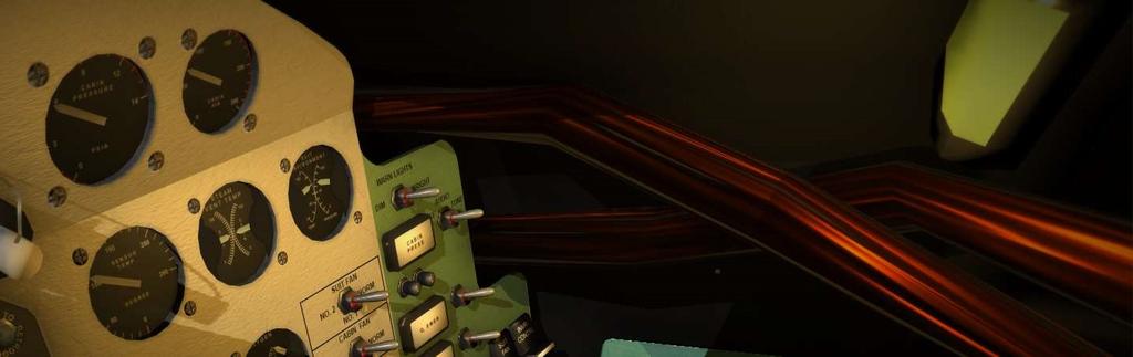
27 IV. ENVIRONMENTAL CONTROL SYSTEM 1. GENERAL The environment in the pressurized cabin is controlled by the ECS, the Environmental Control System. It is operated through automatic systems as well as manually from the control panel. The ECS provides the astronaut with 100% oxygen during flight and landing. It has two independent systems, one for the cabin and one for the pressurized suit the astronaut is wearing. It removes odors, CO2 and moisture from the suit circuit, maintains cabin and suit temperature, and provides oxygen and emergency oxygen. The capsule carries enough oxygen and coolant to sustain life for about 20 orbits. Figure shows the ECS panel, it has 7 gauges for reading the ECS status. Fig ECS Instrumentation 26 P a g e

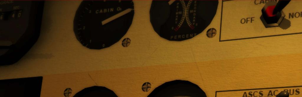
28 2. OXYGEN The ECS consist of two oxygen tanks, one primary and one secondary. These two are identical, except the pressure is lower in the secondary, allowing the primary to deplete first before the secondary takes over. When the primary oxygen tank reaches <10%, the secondary tank takes over. This is fully automatic. The OXYGEN instrument will give you an indication of the amount (percentage) of oxygen left in either of the two oxygen tanks. The two tanks are equal, and gaseous oxygen is stored at 7500 PSI. During launch, the cabin is pressurized with 100% pure oxygen at 16 PSI. This pressure will bleed off during ascent. When the pressure reaches 5.5 PSIA, the regulator will seal the cabin and stop the bleeding. The ECS will try to maintain this pressure for the reminder of the flight. During decent, the ECS will go to emergency mode, using oxygen to quickly circulate air in the cabin and suit. A snorkel will also provide fresh air from outside. The cabin can be decompressed manually by pulling the decompress handle, and repressurized again using the repress handle. This is good in case of fire or toxic gas. If the cabin pressure is out of bounds, a cabin pressure warning light will illuminate. During descent, a SNORKEL is used to open the cabin air inlet so outside air can enter the cabin. This happens automatically but can also be triggered manually by pulling the SNORKEL ring. This is normally used below 20k ft. before landing. 27 P a g e


29 3. COOLING The construction of the cabin is made so it only requires cooling, due to the low head generating equipment and small pressurized compartment. Air is routed through a heat exchanger to cool the air, and a water cooling system cools down the equipment. This water is also passed through heat exchangers, and vented overboard. The heat exchangers temperature can be read using the STEAM VENT TEMP gauge. For the water cooling system, two heat exchangers are used. One is for the cabin circuit, and one for the suit circuit. A water coolant tank provides the cooling water, and temperature controlled on the temperature panel. 28 P a g e

30 Fans are used to force air through the heat exchanger, providing cool air to the system. The cabin circuit got one fan, and the suit circuit got two, one main and one backup. These are operated automatically but can be overridden by the astronaut. If the cabin fan fails, the temperature in the cabin will slowly start to increase. If the suit fan fails, the backup will start automatically. If all the fans fail, an emergency oxygen rate flow is available, and will push oxygen through the circuits at a high rate. This will use the oxygen fast, so if this happens plan an immediate reentry. It is important to monitor the cabin and suit temperature frequently (every 10 minutes), as well as the oxygen quantity and pressure. The CABIN AIR gauge indicates the cabin air temperature, try to keep it below 100 degrees if Fahrenheit. 29 P a g e


31 The SUIT ENVIRONMENT gauge indicates the temperature in the suit circuit. The fans can be controlled using two switches on the main ECS panel, as well as fuses. The SUIT FAN switch controls what suit fan is operational. NORM will let the ECS control the FAN operation. No.1 will manually run the primary fan on the suit circuit, and No.2 will run the secondary/backup fan in the suit circuit. The CABIN FAN switch run the cabin fan. This can be turned off by setting the switch to the OFF position. 30 P a g e


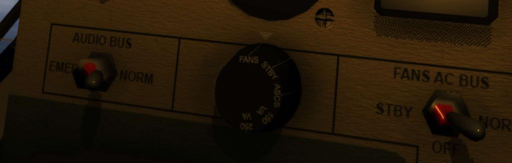
32 A SUIT FAN circuit breaker/fuse controls if any of the fans will be connected to the electrical system. The FANS are using AC power, and is connected to the FANS AC BUS. The FANS AC BUS receives power from the primary or the standby power system. A switch on the electrical panel can be used to connect the FANS AC BUS to the Standby power system if needed. A carbon dioxide filter and odor filter is installed in the circuit. These uses lithium hydroxide and activated charcoal to function, and excess humidity is removed by a sponge that traps water particles. When this sponge is full, it will automatically be squeezed, and the water will flow into a tank. The temperatures can be controlled using the temperature control panel on the right side of the cabin, and the main panel. This panel has 3 rotary switches. Operating these is mandatory during the mission. If you are on the dark side of the Earth, less cooling is needed to keep the environment heated. On the sunny side, more cooling is needed to keep the environment cool. The Emergency O2 handle is also on this panel, and is used if the fans and cooling systems malfunction. 31 P a g e

33 32 P a g e

34 4. CABIN PRESSURE Cabin pressure will bleed during ascent and stabilize at 5.5 PSIA. Cabin Pressure can be monitored using the CABIN PRESSURE gauge: If the cabin pressure cannot be maintained and falls outside of the operating limit, the CABIN PRESS warning light will illuminate, and a tone will sound. This tone can be muted using the switch next to it. In the event of a fire, or any other circumstance where you will need to depressurize the cabin, you can do so by using the two T-handles on the left panel. One is for depressurizing the cabin, and the other is to repressurize it. Keep in mind that repressurizing the cabin needs a lot of oxygen, so pay attention to the oxygen instruments. 33 P a g e


35 5. OPERATION The ECS is fully automatic, and under normal circumstances you only need to check the vital measurements on ECS instrument panel. 4 warning lights with an alarm tone will illuminate when something needs attention. Pay attention to these. 34 P a g e


36 V. FLIGHT CONTROL SYSTEMS 35 P a g e
37 V. FLIGHT CONTROL SYSTEMS 1. GENERAL The capsules attitude and stabilization is controlled by the Automatic Stabilization Control System (ASCS), the Horizon Scanners and the Reaction Control System. Attitude is determined by three gyros indicating pitch, roll and yaw. Three accelerometers are used to detect rate. Three switches control the ASCS. These can configure the capsule to either be controlled automatically, manually or something in-between. The ASCS controls the Reaction Control System (RCS). The RCS is a set of thrusters that can change the capsules attitude. It consists of two systems: System A and System B. System A is meant for automatic modes, and system B is meant for manual modes. 36 P a g e

38 Both system A and B has their own independent fuel tank, and can be monitored using the FUEL gauge: The Horizon Scanners are detecting our attitude relative to the horizon of Earth in front of us. The GYROS can be slaved to these scanners, or be set to FREE mode. In FREE mode, the gyros will change based on thrust input. If the FUEL quantity reached below 25% in any of the tanks, the FUEL QUAN warning light will illuminate. 2. ATTITUDE CONTROL Attitude is sensed by gyros and accelerometers. Two independent systems are used for attitude control, system A and system B. ATTITUDE Attitude is sensed based on your orientation in reference to a stable platform maintained by three gyros. The relative orientation to this platform can be read from the attitude indicators, 37 P a g e

39 and the angular attitude rate is sensed by accelerometers and can be read from the attitude rate indicators. The roll indicator tells you how much you have rolled relative to the stable platform, pitch is your pitch the the stable platform, and yaw is your yaw relative to the stable platform. The square in the middle consists of three arrows. One long horizontal arrow is your pitch rate, while the top vertical arrow is roll rate and the bottom is yaw rate. HORIZON SCANNER & GYROs The GYROs are free, and any stable platform can be set by caging the gyros. Most of the attitude requirements during the mission is relative to Earth. Like the orbit attitude is -34 pitch, 0 yaw and 0 roll. This means that you need to pitch your spacecraft ti -34 relative to Earth. The Earth is detected using Horizon Scanners. These scanners constantly keeps track of the Earth horizon, and the gyros can be slaved to maintain this as the stable platform. The GYRO switch controls your GYRO settings. 38 P a g e

40 GYRO NORM slaves your gyros to the Horizon Scanners, FREE lets the GYROs move based on attitude rate changes, and GYRO CAGE cages the gyros, and returns them to 0,0,0 and keeps them there regardless of attitude or attitude changes. The spacecraft supports orientation 360 degrees in all axes. However, the GYROs don t like this. Moving the spacecraft outside of the gyro operation range will cause them to drift or become unstable. This will give you wrong readings on the attitude indicator. When performing operations outside of the gyro limit, it s advisable to either set the gyros to free, or cage them. This will make you have to realign the gyros again manually. Gyro Operations Limits Pitch: -130 degrees to 90 degrees Yaw: 250 degrees to 70 degrees Roll: -80 degrees to 80 degrees If your GYROs drift, become unstable or stops working, you can use the window as a platform reference, as well as the periscope. It s important to frequently use the gyroscope and window to learn where the horizon is relative to the lines so you know what attitude these indicate. The MANEUVER switch can be used to power down the GYROs. SYSTEM A This system is the AUTOMATIC system, and its fuel are dedicated to the automatic flight controls. There are three automatic flight modes: Automatic Stabilization & Control System, AUX DAMP, and Fly-By-Wire Automatic Stabilization & Control System The ASCS mode orients the spacecraft based on mission phase and the sequencer. It can enter damp mode that damps the attitude rates (like after capsule separation), orient the capsule to 39 P a g e
41 orbit attitude, reentry attitude and so on. The Orbit attitude is the base attitude used through orbital flight. AUX DAMP The AUX DAMP mode will damp out any attitude rates. It will try to hold the spacecraft s orientation in place. This is good if you just want the spacecraft to maintain a given orientation. Fly-By-Wire This system is an electrical orientation system that enables you to use the attitude control stick to change attitude. The thrusters are fired based on what direction to push the control stick. SYSTEM B System B is the MANUAL system. It uses fuel from the MANUAL fuel tank. It can use variable thruster power, and can be used in two different main modes: Manual Proportional and Rate Stabilization & Control System. Manual Proportional You use the attitude control stick to adjust the attitude, and provided variable attitude acceleration. This is the only mode that don t require any electrical power to function. Rate Stabilization & Control System Uses the ASCS as well as the manual control to change the attitude. 3. FLIGHT MODES In section 5.2 we already looked at a few different flight modes. There are more flight modes available using the two flight mode switches mentioned above, and 4 push/pull handles. These handles can be used to combine the different modes. The main handle is MANUAL, witch is needed to enter the MANUAL modes mentioned above. The MANUAL handle switches between the manual (DIRECT) thrusters and the automatic, and the three white handles, one for each axis, is used to cut the fuel supply from the automatic system to these axes. This can be used to let the ASCS control two of the axes, while you control the other. 40 P a g e


42 This section will describe the switch configurations needed to enter the various main flight modes. You can be creative and use others that s not been described here as well. The first switch is named ASCS switch, the 2nd is names RSCS switch and the last is named GYRO switch. 1: FULLY AUTOMATIC The fully automatic mode is using the ASCS only, and provides no manual control. Remember, this mode can fail or the sensors/systems can fail so pay attention and be ready to take over if something happens. CONFIGURATION ASCS to NORM RSCS to AUTO MANUAL handle to PUSH 41 P a g e
43 2: FLY-BY-WIRE The Fly-By-Wire control mode enables you to control the attitude in the automatic mode, thus using fuel from the automatic fuel tank. CONFIGURATION ASCS to FLY-BY-WIRE RSCS to AUTO MANUAL handle to PUSH 3: MANUAL PROPORTIONAL The MP control mode enables you to control the attitude manually, thus using fuel from the manual fuel tank. CONFIGURATION ASCS to AUX or AUTO RSCS to RATE COMD MANUAL handle to PULL DIRECT The ASCS switch can be used to enable AUX damping, or not. 4: RATE COMD This mode allows you to control the attitude of the spacecraft, but when not stick input is detected, the ASCS will fire the thrusters needed to stop the rates. CONFIGURATION ASCS to AUX or AUTO RSCS to RATE COMD MANUAL handle to PUSH RATE COMD 42 P a g e


44 VI. RETROGRADE ROCKET SYSTEM 43 P a g e
45 VI. RETROGRADE ROCKET SYSTEM 1. GENERAL The RETROs are three engines designed to decelerate the capsule in preparation for reentry. It s a critical part of the spacecraft where a lot can go wrong. In short, the retros are the only equipment the spaceship has that can alter the Orbit itself. The attitude controls only changes orientation, but the velocity direction remains unchanged. A lot of caution is needed while operating the retro engines. If you fire them in the wrong orientation, you might alter the orbit in such a way that you never get back to Earth, or reentry too steep and burn up in the atmosphere. The timing of when you fire the retros are also important as it defines where you will land on Earth. You want to fire them so you land in a recovery zone. It can be started automatically by the internal sequencer and TIME TO RETRO or by the astronaut. The three engines will fire for 10 seconds each, with a 5 second time delay between each of them. Once fired, the RETROs will automatically be jettisoned (if RETRO Auto Jett switch is armed), or manually by the astronaut. Due to the importance of these engines, never arm the auto retro squibs unless you plan to jettison them soon, and ensure you have control over the respective fuses. It s a good practice to open and close the fuses based on need. Without the retro engines, you will not have any way of returning to Earth. 2. OPERATION The three retrograde engines are located on the Retrograde Package attached to the blunt end of the capsule. It s attached on the Heat Shield by three straps and explosive bolts. 60 seconds after retrograde, the bolts are detonated and a spring assembly pushes the pack away from the capsule. Each engine is directed relative to the center of gravity to keep the spacecraft stable during retrograde, but some attitude rate can occur. Each rocket delivers about 1000 pounds of thrust for 10 seconds. When they receive the retrofire signal, the No.1 engine will ignite and fire for 10 seconds. 5 seconds after ignition of No.1 engine, No.2 will fire for 10 seconds. 5 seconds after No.2 has ignited, No.3 fires for 10 seconds. Total engine on time is 20 seconds. 44 P a g e
.")


46 The pack also hosts three smaller engines. These are named the posigrade engines and will fire automatically when the capsule is separated from the launch vehicle in the prograde direction. These are only fired for about one second to move the capsule away from the LV. The retrograde engines are fired either automatically based on the TIME TO RETRO timer (Tr). This timer can be set manually, or by the ground station through radio commands. The RETRO SEQUENCE will start when Tr is reached, or manually by pressing the protected RETRO SEQ trigger given that the EMER RETRO SEQ fuse is ON. Left click the protective cover to remove the cover and press the trigger. Once the SEQUENCER initiates the RETRO SEQUENCE, this light will illuminate. At this point you will need to put the capsule in RETROGRADE attitude, and the FIRE RETRO signal is given 30 seconds after. The RETRO DELAY switch can let you choose if the RETRO FIRE signal will happen immediately when the RETRO SEQ has started, or INSTANTLY. NORM is preferred as it gives you time to verify, and use the automatic sequencer to complete the next steps. Use INST only in emergencies. The RETRO ATT will illuminate orange if you are in the wrong attitude. The FIRE RETRO trigger will NOT automatically happen if you are in the wrong attitude. 45 P a g e


47 The switch next to this light allows automatic RETRO ATT event handling to the sequencer. If you put this to bypass, the retros will FIRE regardless of attitude. This is not desired as firing in the wrong direction will make a safe reentry impossible. During ASCS, the ATTITUDE SELECT switch will orient the spacecraft to the selected attitude. 30 seconds before the FIRE RETRO signal is given, a warning light with a tone will trigger to let you know that the engines will soon trigger. At this time, ensure everything is correct and safe, attitude is right and so on just to be sure. When the correct attitude is reached and the RETRO SEQ timer reached 0, the engines will fire given that the RETRO MAN (optional), and NO.1,2,3 RETRO RCKT are ON. 46 P a g e

48 The FIRE RETRO light will be red 10 seconds before the FIRE SIGNAL is given and will switch to green when the retros has fired. If you are not using autopilot here, the RETROS will push the orientation and build up rates. Keep this under control manually. When the retros have fired, it s time to jettison the retro pack as it s no longer needed. To do this, the AUTO RETRO JETT switch and the SQUIBs must be set to ARM. If one of the retros didn t fire due to fuse settings, you can fire it again by enabling the fuse and pressing the manual FIRE RETRO trigger. 60 seconds after the retro fire, the signal to jettison the retros will be given. To manually jettison the retros, you can use the trigger button next to it. The light will turn red two seconds before jettison, and green when complete. The EMER RETRO JETT and RETRO JETT fuses must be on for this to happen. 3. RETROGRADE TIMING The timing of the retro grade fire event varies depending on the altitude and velocity when they are fired, and where in the Orbit you currently are. Missions have preset retrograde times, but these will most likely change. Ground will do this for you, or you can do it manually using the clock. Basically, the lower the altitude, the faster you are going relative to Earth due to the smaller orbit (lower orbit period). At this point, the retros will need to be fired earlier. If you are far out, you are going slower and the retros can be fired later. Generally, the retros are fired about 3000nm miles before the splashdown location. 47 P a g e


49 VII. SEQUENCER 48 P a g e

50 VII. SEQUENCER 1. GENERAL The sequencer is a system that controls all the automatic events, and the sequencer status can be read using the column of lights on the left side of the panel. It indicates what state the capsule is in, what state is being executed, what is completed and what has failed. The sequencer consists of various sensors and switches, relays, time delays to function correctly. It s the state machine of the spacecraft. The sequencer applies power to the various systems, such as the FIRE RETRO signal, or the release of the chutes. It also detects when you separate from the LV, and what mode the ASCS needs to be in. Tower Separation is the first stage and indicates if tower has separated. Capsule separation is the next and indicates if the capsule is separated from the LV. The next set is for RETROs,.05g (atmosphere is detected), DROGUE and MAIN chutes. Each stage can be manually executed by the astronaut, but the sequencer is usually fully automatic. 49 P a g e
51 2. EVENTS The sequencer is operated by using the sequencer panel. Each stage got a light and might have switches or trigger buttons to manually control or aid the sequencer. The sequencer is controlled by the Programmer, so the Programmer fuse must be on for it to operate. Fig shows the Sequencer stages. Fig Sequencer stages, from the SEDR 104 manual At launch, the sequencer will fire the boosters and the sustainer engines. At the right time, the booster engine cutoff will happen (BECO) and it will be jettisoned. 20 seconds after BECO, the tower will be jettisoned, and the TOWER JETT light will illuminate, and the landing system will be armed. Then the sustainer engine will initiate cutoff and the capsule will be separated after a short delay. At cutoff, the posigrade engines will fire to clear some distance from the launch 50 P a g e
52 vehicle. At this point, the ASCS is asked to enter the damp mode, and then perform a 180 yaw turn to attain orbit attitude. Fig Sequence during SECO and Capsule turnaround, from the SEDR 104 manual The retro sequencer will start at the given retro time, and 30 seconds later, then retrograde fire signal will be given. If everything is in order, the retros will fire, and then jettisoned 60 seconds later. At ft. the drogue will be deployed, and the snorkel will be opened. At ft. the main chutes will be deployed, releasing the drogue and jettisoning the antenna, as well as releasing the heat shield and filling the landing bag. 51 P a g e
53 VIII. ELECTRICAL SYSTEM 52 P a g e
54 VIII. ELECTRICAL SYSTEM 1. GENERAL The capsule got both DC and AC power. The DC system is powered by three 3000 watt-hour batteries in series. Two Standby 1500 watt-hour batteries are also available in case of main battery failures. A 1500 watt-hour Isolated battery is also available for squib firing and the emergency audio bus. Prior to launch, power is received through umbilical connection. During failures and emergences, the main DC bus can be connected to the standby DC bus. The Isolated Bus can also be connected to the standby bus. The AC power is created by inverters of 150 and 250 volt-amperes each. Two systems require AC power: The ECS FANS bus and the ASCS bus. A standby 250-volt-ampere inverter can be used in case of failures. If this happens, a warning light will on the panel will let you know - this is fully automatic. Switching the FANS AC or ASCS AC switch from NORM to STBY position control what inverter they are connected to. An ammeter can be used to see how much ampere is being drained from the batteries, a voltmeter can be used to see the status of each battery, and the inverter load. Fuses can turn on or off systems, as well as switches to balance or reduce load on batteries. Battery capacity check can only be done with GROUND by a telemetry radio command. 2. DC POWER The Main Batteries are connected to the Main DC bus through a battery bus. The STBY BTRY switch ties the standby battery bus directly to the Main DC bus. If the Standby Batteries are connected, both the Main batteries and the Standby batteries are powering the Main DC bus. The Isolated Battery is connected to the Isolated Battery bus, powering the Squib Bus and an Emergency Audio bus. The Squib Bus powers the pyros needed for staging and sequencing. If 53 P a g e


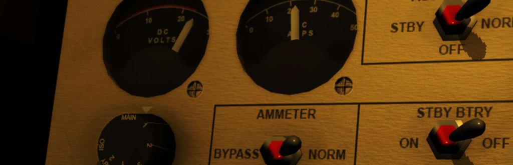
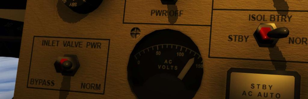
55 this fails, the Isolated bus can be tied to the Standby bus for power using the ISOL BTRY switch. The AUDIO BUS switch can tie the AUDIO BUS to the ISOLATED Battery. The DC Amps load on the various batteries and the Main bus can be read using the Ammeter. The DC Volts indicates the voltage of the selected system, meaning if it s producing power, and how much it produces. The system that you want to look at can be changed using the rotator knob. MAIN shows the volts and load on the MAIN DC bus, 1,2,3 shows battery status, SBY 1,2 shows standby battery status and ISO shows the Isolated Battery status. If a voltage is low, something is wrong. The voltage should display a value around 24 volts. The DC amps shows the load on the system. Turning on or off systems will increase/reduce the power load on the power sources. 54 P a g e


56 The AMMETER switch can either be bypassed (to conserve power if needed) or operate normally in the NORM position. Powering the AMMETER OFF will remove power to the entire MAIN DC bus. 3. AC POWER & INVERTERS Three INVERTERs produce AC power to operate the ASCS AC Bus and the FANS AC bus. The three inverters are the Standby Inverter (250 VA), Main Inverter (150 VA, Fans) and another Main Inverter (250VA, ASCS). AC Volts on the various components can be read by the AC VOLTS gauge, controlled by the AC VOLTS selector rotator switch. The ASCS AC BUS switch can be used to switch the ASCS AC Bus from the main inverter to the standby inverter. The FANS AC BUS switch can be used to switch the FANS AC Bus from the main inverter to the standby inverter. 55 P a g e


57 The STBY AC AUTO light will illuminate if the Standby Inverter is being used. 4. LIGHTS There are a good number of light bulbs in the spacecraft. The chance that any of them might fail is small, but the event can be catastrophic. If a light turns off during a system failure, or turns on during normal operations when it should not a wrong reaction can be triggered. To ensure that all the lights are functional, you can perform a light bulb test using the LIGHT TEST switch. Middle is normal state, while the right is to test all red lights, and left is to test all green lights. Left will also illuminate the red bulbs where no green light exists. 56 P a g e

58 The switch can be found next the the MANEUVER switch on the lower left central panel. 57 P a g e


59 There are two cabin lights. One on the left side and one on the right side. Clicking the light itself when it s on will apply or remove a red filter. The CABIN LIGHT switch allows you to select what light is on or off. 5. FUSES There are is a huge range of fuses, and for the beginners it s best to just leave them on unless told otherwise by the checklists, or during malfunctions. Each fuse switch has three positions. Position 1 is UP, OFF is middle and 2 is down. Each fuse has two fuses, No.1 and No.2, for redundancy. 58 P a g e


60 All the fuses are located on two different panels. One on the left side, and one on the right side. All of the fuses are functional, so you should spend some time locating each, and understanding what system they belong to. 59 P a g e


61 IX. COMMUNICATION 60 P a g e
 for backup and reentry use, and two identical UHF (Ultra High-Frequency) antennas for primary use.")
62 IX. COMMUNICATION 1. GENERAL The capsule has three antennas that is used for communication. One HF (High-Frequency) for backup and reentry use, and two identical UHF (Ultra High-Frequency) antennas for primary use. One high powered amplified UHF antenna is used as primary, and in case of failures, a low powered normal UHF antenna is used. The best range is the amplified UHF antenna. 2. OPERATION The C key on the keyboard will bring up the Radio Command menu, and you can select what commands to send to GROUND. If GROUND sends you a message, it can be read in the communication window. There are many ground stations around the Earth that will be in range with you when you travel around the globe. As they get within range, they will let you know (if your radio is on). If you don t hear anything, you can send a Always ensure (if possible) a communication link with ground is active. You can check connection status by a radio command. If no reply, change radio settings to backup UHF or HF and try again. Telemetry is also seen by ground and you can check status based on this, like battery status and so on. If they can't see telemetry, you can change telemetry settings and try again. A map is available showing you what stations are nearby. Remember, the green ring is an indicator, and the range is usually stretching a bit longer than what it indicates. The Radio is operated using the panel below the Electrical Control Panel. 61 P a g e

63 The UHF switch selects what UHF system you want to use. Either the Main HI PWR antenna, or the backup LO PWR antenna. The HI PWR UHF antenna has the longest range. The Transmit switch selects if the HF radio system should be used, or the selected UHF antenna. Beacon sends out a continues beacon signal for recovery and tracking. VOX can also be used instead of the C key to bring up the radio command menu. 62 P a g e
64 X. NAVIGATIONAL AIDS 63 P a g e

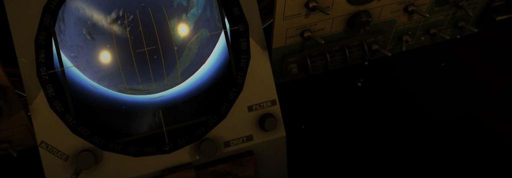
65 X. NAVIGATIONAL AIDS 1. GENERAL The Mercury Capsule comes with a set of equipment that can be used to aid you while operating the spacecraft, and orient the spacecraft if the GYROs or the attitude indicators would fail. This includes the Periscope located in the lower part of the center panel, a satellite clock, the Earth Path Indicator, an Altimeter and a longitudinal altimeter. 2. THE PERISCOPE The Periscope is a tool that can aid you in orienting the spacecraft, check the drift and motion relative to Earth. The periscope is retracted during launch and descent, and extended for the rest of the mission. A fuse can be used to turn it on or off, or a black filter can be applied to avoid any light to enter the cockpit. The periscope panel contains all the controls needed to control it. One knob is used to move bars around the globe to measure the altitude, one for turning the drift lines, one to apply magnification and apply a filter to the light entering the cockpit. A retract light is illuminated when the periscope should be retracted. 64 P a g e
66 Both the FILTER and MAGNIFY knob is added to this panel in Reentry due to accessibility. Fig shows the periscope components. Note that some of the features is not yet implemented. Fig The Periscope, from SEDR 104 manual 65 P a g e
67 The position of Earth can help you understand the attitude. If it s centered, the roll and yaw is level. If it s on the indicated lines on the globe screen, you are in retrograde attitude. The position of Earth in the vertical axis indicates your pitch. 66 P a g e


68 XI. REENTRY & LANDING 67 P a g e
69 XI. REENTRY & LANDING The landing sequence is completely automatic, but manual override controls can be used to do this manually. Landing consists of a few stages, the retrograde phase, the reentry phase and the landing/recovery phase, figure shows this. Figure Landing, from SEDR 104 manual 1. RETROGRADE The retrograde rockets can be fired in multiple ways. As indicated in chapter VI, the retrograde rockets are fired either by automatically or manually. Once the retrograde rockets have fired, the reentry phase of the mission has started and the spaceship has no additional ways to alter the orbit. The retrograde rockets are jettisoned after the retro fire, exposing the headshield. 68 P a g e


70 2. REENTRY Before reentry, the REENTRY switch is places to the REENTRY position. If the capsule is automatically controlled by the ASCS, the attitude will be change to the reentry attitude. If manual control is being used, this attitude must be attained and maintained manually. At this time, the 0.5g sensor is waiting to detect the atmosphere. Once the atmosphere is detected, a 10 deg/s roll is established. If this sensor is not functional, the.05g state may be initiated manually but pressing the.05g trigger button manually. 3. LANDING The automatic landing system consist of a drogue parachute used to decelerate and stabilize the capsule, a main parachute used to decelerate the capsule to a landing speed, and a landing bag that will inflate before impact to reduce the impact force. There are two baroswitches, one is for ft. and another for ft. The ft. baroswitch will trigger the deployment of the drogue chute, while the ft. baroswitch will release the drogue and deploy the main chute. The Drogue is automatically deployed, but can manually be deployed during an emergency by pushing the DROGUE trigger button. A snorkel is used to allow air to enter the cabin during the landing phase. This is also automatically opened, but can manually be opened by pulling the SNORKEL trigger ring. 69 P a g e


71 The main chute is automatically deployed, but can manually be deployed using the MAIN trigger ring, and if this is malfunctioning, a reserve chute is also available and can be deployed by pulling the RESERVE trigger ring. When the main chute are deployed, the antenna and the drogue are released. The landing bag is also automatically deployed, but can be inflated manually using the landing bag switch. This switch has three positions. AUTO will let the sequencer control it. OFF will turn it completely off, and MAN will inflate if manually. If manual control is desired, set it to OFF and then to MAN when you need to inflate it. 70 P a g e
72 Figure shows the sequence of the parachutes manual deploy. Fig Emergency landing flow, from SEDR 104 manual 71 P a g e
73 An overview of the landing and recovery systems can be seen in Figure Figure Landing and Recovery systems, from SEDR P a g e


74 Not all of these systems are modelled or simulated in REENTRY, but the entire sequence can be followed based on the checklists. When the capsuel touches the water, the debrief screen is automatically shown and you get an overview of your completed and not completed mission objectives. 73 P a g e

75 XII. CHECKLISTS 74 P a g e
Statement of Work Requirements Verification Table - Addendum
 Statement of Work Requirements Verification Table - Addendum Vehicle Requirements Requirement Success Criteria Verification 1.1 No specific design requirement exists for the altitude. The altitude is a
6. The Launch Vehicle
 6. The Launch Vehicle With the retirement of the Saturn launch vehicle system following the Apollo-Soyuz mission in summer 1975, the Titan III E Centaur is the United State s most powerful launch vehicle
Welcome to Vibrationdata
 Welcome to Vibrationdata Acoustics Shock Vibration Signal Processing September 2010 Newsletter Cue the Sun Feature Articles This month s newsletter continues with the space exploration theme. The Orion
CHAPTER 2 GENERAL DESCRIPTION TO LM-3C
 GENERAL DESCRIPTION TO LM-3C 2.1 Summary Long March 3C (LM-3C) is developed on the basis of LM-3A launch vehicle. China Academy of Launch Vehicle Technology (CALT) started to design LM-3A in mid-1980s.
Warning! Before continuing further, please ensure that you have NOT mounted the propellers on the MultiRotor.
 Mission Planner Setup ( optional, do not use if you have already completed the Dashboard set-up ) Warning! Before continuing further, please ensure that you have NOT mounted the propellers on the MultiRotor.
REFERENCE: 2861 wings 2044 trunk 4904 total BEW 10,655 BOW 11,185 Max Useful load 5115 MLanding ZFW FUEL BURNS 11min min min
 REFERENCE: 2861 wings 2044 trunk 4904 total BEW 10,655 BOW 11,185 Max Useful load 5115 MLanding 15700 ZFW 13000 FUEL BURNS 11min 357 27min 730 36 min 940 58min 1453 1:17 1800 2:20 2933 2:46 3283 3:00 3600
CRITICAL DESIGN REVIEW. University of South Florida Society of Aeronautics and Rocketry
 CRITICAL DESIGN REVIEW University of South Florida Society of Aeronautics and Rocketry 2017-2018 AGENDA 1. Launch Vehicle 2. Recovery 3. Testing 4. Subscale Vehicle 5. Payload 6. Educational Outreach 7.
CHECKLIST 1969 CESSNA 172-K. NOTE: Verify all information with airplane's POH
 CHECKLIST 1969 CESSNA 172-K NOTE: Verify all information with airplane's POH PRE-FLIGHT INSPECTION 1 CABIN 1 A.R.R.O.W. CHECK Airworthiness Cert. In Clear View Registration In Clear View Radio License
SpaceLoft XL Sub-Orbital Launch Vehicle
 SpaceLoft XL Sub-Orbital Launch Vehicle The SpaceLoft XL is UP Aerospace s workhorse space launch vehicle -- ideal for significant-size payloads and multiple, simultaneous-customer operations. SpaceLoft
Caution Notes. Features. Specifications. Installation. A3 3-axis Gyro & Stabilizer User Manual V1.0
 Caution Notes Thank you for choosing our products. If any difficulties are encountered while setting up or operating it, please consult this manual first. For further help, please don t hesitate to contact
Pre-Launch Procedures
 Pre-Launch Procedures Integration and test phase This phase of operations takes place about 3 months before launch, at the TsSKB-Progress factory in Samara, where Foton and its launch vehicle are built.
How to use the Multirotor Motor Performance Data Charts
 How to use the Multirotor Motor Performance Data Charts Here at Innov8tive Designs, we spend a lot of time testing all of the motors that we sell, and collect a large amount of data with a variety of propellers.
Setup and Programming Manual
 Microprocessor and Handy Terminal Setup and Programming Manual Versions U04 to U19 for Sliding Door Systems P/N 159000 Rev 7-2-07 The manufacturer, NABCO Entrances, Inc. suggests that this manual be given
Strap-on Booster Pods
 Strap-on Booster Pods Strap-On Booster Parts List Kit #17052 P/N Description Qty 10105 AT-24/12 Slotted (Laser Cut) Tube 2 10068 Engine Mount (AT-18/2.75) Tube 2 13029 CR 13/18 2 13031 CR 18/24 4 14352
AERO. Meet the Aero. Congratulations on your purchase of an Aero!
 AERO Congratulations on your purchase of an Aero! Please read the following sections of this manual to get started with your new autonomous aircraft. 1 Meet the Aero 7 Fly-by-wire mode 2 Safety 8 Command
CHAPTER 2 GENERAL DESCRIPTION TO LM-2E
 GENERAL DESCRIPTION TO LM-2E 2.1 Summary Long March 2E (LM-2E) is developed based on the mature technologies of LM-2C. China Academy of Launch Vehicle Technology (CALT) started the conceptual design of
Electrical System B-17 Technical Session for Flight Engineers
 Electrical System B-17 Technical Session for Flight Engineers 7/12/2017 GULF COAST WING---COMMEMORATIVE AIR FORCE Boeing B17 N7227C (Texas Raiders - TR) Prepared by Jim Hower The intent of this guide is
Pilot's Operating Handbook Supplement AS-03
 POH / AFM SECTION 9 Pilot's Operating Handbook Supplement ASPEN EFD1000 PFD This supplement is applicable and must be inserted into Section 9 of the POH when the Aspen Avionics Evolution Flight Display
It has taken a while to get
 HOVERING15 99 15 BASICS HOVERING Hovering It has taken a while to get here, but this is what all the building and planning were for to see light under those skids. But this is also the time when you have
TECHNICAL PAPER 1002 FT. WORTH, TEXAS REPORT X ORDER
 I. REFERENCE: 1 30 [1] Snow Engineering Co. Drawing 80504 Sheet 21, Hydraulic Schematic [2] Snow Engineering Co. Drawing 60445, Sheet 21 Control Logic Flow Chart [3] Snow Engineering Co. Drawing 80577,
NOS -36 Magic. An electronic timer for E-36 and F1S Class free flight model aircraft. January This document is for timer version 2.
 NOS -36 Magic An electronic timer for E-36 and F1S Class free flight model aircraft January 2017 This document is for timer version 2.0 Magic Timers Copyright Roger Morrell January 2017 January 2017 Page
Flight Readiness Review Addendum: Full-Scale Re-Flight. Roll Induction and Counter Roll NASA University Student Launch.
 Flight Readiness Review Addendum: Full-Scale Re-Flight Roll Induction and Counter Roll 2016-2017 NASA University Student Launch 27 March 2017 Propulsion Research Center, 301 Sparkman Dr. NW, Huntsville
CRITICAL DESIGN PRESENTATION
 CRITICAL DESIGN PRESENTATION UNIVERSITY OF SOUTH ALABAMA LAUNCH SOCIETY BILL BROWN, BEECHER FAUST, ROCKWELL GARRIDO, CARSON SCHAFF, MICHAEL WIESNETH, MATTHEW WOJCIECHOWSKI ADVISOR: CARLOS MONTALVO MENTOR:
Reentry Demonstration Plan of Flare-type Membrane Aeroshell for Atmospheric Entry Vehicle using a Sounding Rocket
 AIAA ADS Conference 2011 in Dublin 1 Reentry Demonstration Plan of Flare-type Membrane Aeroshell for Atmospheric Entry Vehicle using a Sounding Rocket Kazuhiko Yamada, Takashi Abe (JAXA/ISAS) Kojiro Suzuki
mz-12 & GR-18 Setup Tutorial
 mz-12 & GR-18 Setup Tutorial INTRODUCTION Thank you for purchasing the mz-12 COPTER radio. This radio is the first of its kind that lets you fly your multirotor without the need of complex setups, computer
FIRST FLYING TECHNIQUES COCKPIT PREPARATION STARTUP TAXI
 1. Introduction FIRST FLYING TECHNIQUES COCKPIT PREPARATION STARTUP TAXI We aim to teach and demonstrate how to operate a general aviation aircraft and show some basic techniques and manoeuvres that every
Super Squadron technical paper for. International Aerial Robotics Competition Team Reconnaissance. C. Aasish (M.
 Super Squadron technical paper for International Aerial Robotics Competition 2017 Team Reconnaissance C. Aasish (M.Tech Avionics) S. Jayadeep (B.Tech Avionics) N. Gowri (B.Tech Aerospace) ABSTRACT The
NASA SL - NU FRONTIERS. PDR presentation to the NASA Student Launch Review Panel
 NASA SL - NU FRONTIERS PDR presentation to the NASA Student Launch Review Panel 1 Agenda Launch Vehicle Overview Nose Cone Section Payload Section Lower Avionic Bay Section Booster Section Motor Selection
Blue Origin Achievements and plans for the future
 Blue Origin Achievements and plans for the future Blue Origin A private aerospace manufacturer and spaceflight services company Founded in 2000 by Amazon.com CEO Jeff Bezos Headquarters in Kent (Seattle),
HPR Staging & Air Starting By Gary Stroick
 Complex Rocket Design Considerations HPR Staging & Air Starting By Gary Stroick 1. Tripoli Safety Code 2. Technical Considerations 3. Clusters/Air Starts 4. Staging 5. Summary 2 1. Complex High Power Rocket.
SP4 DOCUMENTATION. 1. SP4 Reference manual SP4 console.
 SP4 DOCUMENTATION 1. SP4 Reference manual.... 1 1.1. SP4 console... 1 1.2 Configuration... 3 1.3 SP4 I/O module.... 6 2. Dynamometer Installation... 7 2.1. Installation parts.... 8 2.2. Connectors and
DCC-2500 Digital Climate Control for Vintage Air GEN-IV systems
 INSTALLATION AND OPERATOR S MANUAL FOR DCC-2500 Digital Climate Control for Vintage Air GEN-IV systems PARTS INCLUDED WITH THIS SYSTEM Vent sensor housings: 2 1 / 2 housings (x2) 2 housings (x2) Installation/operator
PROJECT AQUILA 211 ENGINEERING DRIVE AUBURN, AL POST LAUNCH ASSESSMENT REVIEW
 PROJECT AQUILA 211 ENGINEERING DRIVE AUBURN, AL 36849 POST LAUNCH ASSESSMENT REVIEW APRIL 29, 2016 Motor Specifications The team originally planned to use an Aerotech L-1520T motor and attempted four full
Antares Rocket Launch recorded on 44 1 Beyond HD DDR recorders Controlled by 61 1 Beyond Systems total
 The 1 Beyond ultra-reliable Event DDR and Storage design won the NASA contract to supply the world s largest HD-DDR event recorder which is critical to the new Antares Rocket countdown and launch control
AIRPLANE FLIGHT MANUAL AQUILA AT01 AIRPLANE FLIGHT MANUAL - SUPPLEMENT AVE28 GLASS COCKPIT. equipped with ASPEN EFD1000 PFD
 SECTION 9 AIRPLANE FLIGHT MANUAL - SUPPLEMENT AVE28 GLASS COCKPIT equipped with ASPEN EFD1000 PFD This AFM supplement is applicable and must be inserted into Section 9 of the Airplane Flight Manual when
Operation Manual. IMPORTANT Read before flying!
 Operation Manual IMPORTANT Read before flying! Contents 01 Meet IRIS 03 Parts 04 Charging the Battery 06 Attaching Propellers 07 Safety and Failsafes 08 Learn to Fly 11 Flight Modes 13 Return to Launch
Cessna 172 Skyhawk. Aircraft Checklist Models: R & S
 Cessna 172 Skyhawk Aircraft Checklist Models: R & S This is an abbreviated checklist. Most explanatory items, notes cautions and warnings have been omitted for brevity. Procedures in red/bold text in this
Automated Control Electronics (ACE ) System Operation and Diagnostics
 System Operation and Diagnostics") Commercial Products Automated Control Electronics (ACE ) System Operation and Diagnostics PART NO. 98962SL This page is intentionally blank. Table of Contents Introduction... 1 Controller Operation and
Commercial Products Automated Control Electronics (ACE ) System Operation and Diagnostics PART NO. 98962SL This page is intentionally blank. Table of Contents Introduction... 1 Controller Operation and
Deployment and Flight Test of Inflatable Membrane Aeroshell using Large Scientific Balloon
 1 Deployment and Flight Test of Inflatable Membrane Aeroshell using Large Scientific Balloon Kazuhiko Yamada, Takashi Abe (JAXA/ISAS) Kojiro Suzuki, Naohiko Honma, Yasunori Nagata, Masashi Koyama (The
V - Speeds. RV-10 V fe Flaps Speeds Trail (0 deg) Half (15 deg) Full (30 deg) 122 kias 96 kias. 80 kias
 Half (15 deg) Full (30 deg) 122 kias 96 kias. 80 kias") RV-10 Check List V - Speeds RV-10 V fe Flaps Speeds Trail (0 deg) Half (15 deg) Full (30 deg) 122 kias 96 kias 87 kias V s1 Stall (Flap Up) 60 kias V s0 Stall (Flap 40 deg) 55 kias Best Glide 80 kias V
RV-10 Check List V - Speeds RV-10 V fe Flaps Speeds Trail (0 deg) Half (15 deg) Full (30 deg) 122 kias 96 kias 87 kias V s1 Stall (Flap Up) 60 kias V s0 Stall (Flap 40 deg) 55 kias Best Glide 80 kias V
24 ELECTRICAL DC ELECTRICAL SYSTEM DESCRIPTION
 24 ELECTRICAL DC ELECTRICAL SYSTEM DESCRIPTION The Direct Current electrical system provides power to most equipment through an electrical bus system. The power may be supplied from one of three sources:
Idle Timer Controller - ITC515-A Ford Transit Contact InterMotive for additional vehicle applications
 An ISO 9001:2008 Registered Company Idle Timer Controller - ITC515-A 2015-2018 Ford Transit Contact InterMotive for additional vehicle applications Overview The ITC515-A system will shut off gas or diesel
CHANGING ENTRY, DESCENT, AND LANDING PARADIGMS FOR HUMAN MARS LANDER
 National Aeronautics and Space Administration CHANGING ENTRY, DESCENT, AND LANDING PARADIGMS FOR HUMAN MARS LANDER Alicia Dwyer Cianciolo NASA Langley Research Center 2018 International Planetary Probe
GENERAL The AuRACLE Engine Management System primary display provides a graphical representation of the following engine instrumentation:
 GENERAL The AuRACLE Engine Management System primary display provides a graphical representation of the following engine instrumentation: o Manifold Pressure (MAP) o RPM o Fuel Flow (FF) o Turbine Inlet
Rocketry and Spaceflight Teleclass Webinar!
 Wednesday August 12, 2015 at 12pm Pacific Name Welcome to the Supercharged Science Rocketry and Spaceflight Teleclass Webinar! You can fill out this worksheet as we go along to get the most out of time
PILOT S GUIDE. for the XX Series Electric Attitude Indicator with Battery Backup
 PILOT S GUIDE for the 4300-6XX Series Electric Attitude Indicator with Battery Backup Mid-Continent Instruments and Avionics 9400 E. 34 th Street N., Wichita, KS 67226 USA Phone 316-630-0101 Fax 316-630-0723
Cessna Citation XLS - Electrical
 GENERAL Electrical power for the Citation XLS comes primarily from DC sources originating with the starter/ generators, the Auxiliary Power Unit (APU) or the battery. A receptacle below the left engine
The Car Tutorial Part 2 Creating a Racing Game for Unity
 The Car Tutorial Part 2 Creating a Racing Game for Unity Part 2: Tweaking the Car 3 Center of Mass 3 Suspension 5 Suspension range 6 Suspension damper 6 Drag Multiplier 6 Speed, turning and gears 8 Exporting
Exploration 4: Rotorcraft Flight and Lift
 Exploration 4: Rotorcraft Flight and Lift Students use appropriate terminology to describe the various stages of flight and discover that the lift force changes with the amount of air moved by the rotor
DCC-3000 Climate Control for Vintage Air GEN-IV systems
 INSTALLATION AND OPERATOR S MANUAL FOR DCC-3000 Climate Control for Vintage Air GEN-IV systems PARTS INCLUDED WITH THIS SYSTEM Vent sensor housings: 2 1 / 2 housings (x2) 2 housings (x2) Installation/operator
ITCEMS950 Idle Timer Controller - Engine Monitor Shutdown Isuzu NPR 6.0L Gasoline Engine
 Introduction An ISO 9001:2008 Registered Company ITCEMS950 Idle Timer Controller - Engine Monitor Shutdown 2014-2016 Isuzu NPR 6.0L Gasoline Engine Contact InterMotive for additional vehicle applications
PILOT S GUIDE. for the XXX Series Electric Attitude Indicator with Battery Backup
 PILOT S GUIDE for the 4300-XXX Series Electric Attitude Indicator with Battery Backup Mid-Continent Instruments and Avionics 9400 E. 34 th Street N., Wichita, KS 67226 USA Phone 316-630-0101 Fax 316-630-0723
Troubleshooting of the LubeTech Grease System
 Troubleshooting of the LubeTech Grease System February 2009 The LubeTech grease system is designed to be a preventative maintenance system that will extend the life of your bearings that are connected
64MM F-16 Fighting Falcon V2
 64MM F-16 Fighting Falcon V2 SIMPLE Simple assembly RIGID STRONG DURABLE EPO STABLE SMOOTH FLYING PERFORMANCE FMSMODEL.COM Table of Contents Introductions 3 Contents of Kit 4 Assemble the plane 5 Battery
LUNAR INDUSTRIAL RESEARCH BASE. Yuzhnoye SDO proprietary
 LUNAR INDUSTRIAL RESEARCH BASE DESCRIPTION Lunar Industrial Research Base is one of global, expensive, scientific and labor intensive projects which is to be implemented by the humanity to meet the needs
Electrical Systems. Introduction
 Electrical Systems Figure 1. Major Components of the Car s Electrical System Introduction Electricity is used in nearly all systems of the automobile (Figure 1). It is much easier to understand what electricity
Vso 61. Vs1 63. Vr 70. Vx 76. Vxse 78. Vy 89. Vyse. 89 (blue line) Vmc. 61 (radial redline) Vsse 76. Va 134) Vno 163
 Vmc. 61 (radial redline) Vsse 76. Va 134) Vno 163") PA34-200T Piper Seneca II Normal procedures V-speeds Knots Vso 6 Vs 63 Vr 70 Vx 76 Vxse 78 Vy 89 Vyse Vmc 89 (blue line) 6 (radial redline) Vsse 76 Va 2-36(@4507lbs 34) Vno 63 Vfe 38 (0*)/2(25*)/07(40*)
PA34-200T Piper Seneca II Normal procedures V-speeds Knots Vso 6 Vs 63 Vr 70 Vx 76 Vxse 78 Vy 89 Vyse Vmc 89 (blue line) 6 (radial redline) Vsse 76 Va 2-36(@4507lbs 34) Vno 63 Vfe 38 (0*)/2(25*)/07(40*)
Attitude And Direction
 CIRRUS AIRPLANE MAINTENANCE MANUAL Attitude And Direction CHAPTER 34-20: ATTITUDE AND DIRECTION GENERAL 34-20: ATTITUDE AND DIRECTION 1. General This section contains information pertaining to those portions
Volvo SCR testing module
 Volvo SCR testing module Brief module description We design this module to test the Volvo SCR system (subsequently SCR) and its components. Using this module, you can test different SCR components, such
AERO. Meet the Aero. Congratulations on your purchase of an Aero!
 AERO Congratulations on your purchase of an Aero! Please read the following sections of this manual to get started with your new autonomous aircraft. 1 Meet the Aero 7 Fly-by-wire mode 2 Safety 8 Command
RR Concepts. The StationMaster can control DC trains or DCC equipped trains set to linear mode.
 Jan, 0 S RR Concepts M tation aster - 5 Train Controller - V software This manual contains detailed hookup and programming instructions for the StationMaster train controller available in a AMP or 0AMP
NASA - USLI Presentation 1/23/2013. University of Minnesota: USLI CDR 1
 NASA - USLI Presentation 1/23/2013 2013 USLI CDR 1 Final design Key features Final motor choice Flight profile Stability Mass Drift Parachute Kinetic Energy Staged recovery Payload Integration Interface
GPS Steering System Installation Manual
 GPS Steering System Installation Manual Supported Vehicles Challenger Massey Ferguson AGCO MT-645C, MT-645D MF-8650 DT-205B MT-655C, MT-655D MF-8660 DT-225B MT-665C, MT-665D MF-8670 DT-250B MT-675C, MT-675D
Bombardier Challenger Auxiliary Power Unit
 GENERAL A Honeywell 36 150(CL) constant-speed gas turbine auxiliary power unit (APU) is installed within a fire-resistant compartment in the aft equipment bay. The APU drives a generator, providing AC
2001 Dodge Durango ACCESSORIES & EQUIPMENT' 'Anti-Theft Systems - Dakota & Durango 2001 ACCESSORIES & EQUIPMENT
 DESCRIPTION VEHICLE THEFT SECURITY SYSTEM 2001 ACCESSORIES & EQUIPMENT Anti-Theft Systems - Dakota & Durango Vehicle Theft Security System (VTSS) provides perimeter protection against unauthorized use
INSTALLATION MANUAL AND OPERATING INSTRUCTIONS XX and XX Series Electric Attitude Indicator
 INSTALLATION MANUAL AND OPERATING INSTRUCTIONS 4300-3XX and 4300-5XX Series Electric Attitude Indicator MID-CONTINENT INST. CO., INC MANUAL NUMBER 9015692 Copyright 2003 Mid-Continent Instrument Co., Inc.
Deployment and Drop Test for Inflatable Aeroshell for Atmospheric Entry Capsule with using Large Scientific Balloon
 , Germany Deployment and Drop Test for Inflatable Aeroshell for Atmospheric Entry Capsule with using Large Scientific Balloon Kazuhiko Yamada, Takashi Abe (JAXA/ISAS) Kojiro Suzuki, Naohiko Honma, Yasunori
FC151. FC151 Flight Control System Instruction Manual. #21436
 Shanghai Dualsky Models co.,ltd. Rm.1016,No.201,Xin Jin Qiao Rd.,Shanghai,China. Tel: +86 21 50322162 Fax: +86 21 50322163 Flight Control System Instruction Manual Made in China 41ZX15F0810 #21436 http://www.dualsky.com
Auburn University. Project Wall-Eagle FRR
 Auburn University Project Wall-Eagle FRR Rocket Design Rocket Model Mass Estimates Booster Section Mass(lb.) Estimated Upper Section Mass(lb.) Actual Component Mass(lb.) Estimated Mass(lb.) Actual Component
Dealing with customer concerns related to electronic throttle bodies By: Bernie Thompson
 Dealing with customer concerns related to electronic throttle bodies By: Bernie Thompson In order to regulate the power produced from the gasoline internal combustion engine (ICE), a restriction is used
EV Display User Guide
 EV Display User Guide CleanPowerAuto LLC Brief Description: EV Display is designed to track battery state of charge and other related data in battery powered Electric Vehicle. EV Display is primarily designed
PF3100 TROUBLESHOOTING SOLUTIONS TO COMMON PROBLEMS. v1.1 Revised Nov 29, 2016
 PF3100 TROUBLESHOOTING SOLUTIONS TO COMMON PROBLEMS v1.1 Revised Table of Contents 1 Common Alarms and Warnings... 1 2 Common Issues... 6 2.1 Communication problems... 6 2.1.1 Controller communication
52 BACKYARDFLYER.COM FLY
 52 BACKYARDFLYER.COM FLY HELIS IN1O EASY STEPS by Klaus Ronge Photography by Hope McCall & Pete Hall Flying model helicopters is exciting and fun and looks very easy, that is, until you try it. Unlike
USE AN ENGINEERED APPROACH TO TAILOR A PERFECT STANDARD GAS SPRING FOR YOUR DESIGN A GUIDE TO GAS SPRING DESIGN AND CUSTOMIZATION WH ITE PA P E R
 WH ITE PA P E R USE AN ENGINEERED APPROACH TO TAILOR A PERFECT STANDARD GAS SPRING FOR YOUR DESIGN A GUIDE TO GAS SPRING DESIGN AND CUSTOMIZATION When your machine design calls for an industrial gas spring,
SAFETY WARNING Please read these before operating your Sky Vector
 www.megatech.com Entire contents Megatech 2002 Congratulations! You have just purchased the EASIEST plane to fly in the world! Learning to fly has never been so fun! Get ready to hand launch into gravity-defying
On Line UPS. LUC 1000E / LUC 2000E / LUC 3000E User Manual
 On Line UPS LUC 1000E / LUC 2000E / LUC 3000E User Manual Save This Manual Please read this manual carefully prior to storage, installation, wiring, operation and maintenance of the UPS. This manual contains
EPAS Desktop Pro Software User Manual
 Software User Manual Issue 1.10 Contents 1 Introduction 4 1.1 What is EPAS Desktop Pro? 4 1.2 About This Manual 4 1.3 Typographical Conventions 5 1.4 Getting Technical Support 5 2 Getting Started 6 2.1
Critical Design Review
 Critical Design Review University of Illinois at Urbana-Champaign NASA Student Launch 2017-2018 Illinois Space Society 1 Overview Illinois Space Society 2 Launch Vehicle Summary Javier Brown Illinois Space
WirelessAIR Advanced Integrated Remote
 Advanced Integrated Remote Gen 3 Kit 72000 Automatic Leveling Digital On-Board Compressor System MN-772 (021112) ECR 7233 INSTALLATION GUIDE For maximum effectiveness and safety, please read these instructions
READ BEFORE STARTING PLEASE INSTALLATION! User Manual
 PLEASE READ BEFORE STARTING INSTALLATION! User Manual Contents 1 Scope of delivery3 2 Overview of the RaceChip 4 3 Installation 5 4 Fine tuning 14 5 Trouble Shooting 16 6 Contact 20 Overview and explanation
Begin to Use The New ESC: Before use the new ESC please carefully check every connections are correct or not. Yellow motor wire B Blue motor wire A
 HIMOTO ZTW Brushless Electronic Speed Control for car or truck Thank you for purchasing ZTW Brushless Electronic Speed Controller(ESC). The ZTW electronic speed control (ESC) is specifically designed for
Tecomotive - tinycwa User Manual
 Tecomotive - tinycwa User Manual Overview Contents - tinycwa controller - Fuse holder - Fuses (15A/30A) - Connector 8 pin (controller) - Connector 4 pin (water pump) - Connector 2 pin (temperature sensor)
XIV.C. Flight Principles Engine Inoperative
 XIV.C. Flight Principles Engine Inoperative References: FAA-H-8083-3; POH/AFM Objectives The student should develop knowledge of the elements related to single engine operation. Key Elements Elements Schedule
QUICK REFERENCE FOR DEPARTURE (updated 05/22/08)
") Mariah QUICK REFERENCE FOR DEPARTURE (updated 05/22/08) The Quick Reference for Departure is just that condensed checklists and reminders. It assumes that the charter guest/operator is experienced and
Mariah QUICK REFERENCE FOR DEPARTURE (updated 05/22/08) The Quick Reference for Departure is just that condensed checklists and reminders. It assumes that the charter guest/operator is experienced and
Operation Manual. IMPORTANT Read before flying!
 Operation Manual IMPORTANT Read before flying! Contents 01 Meet IRIS-M 03 Parts 04 Charging the Battery 05 Battery Safety 06 Attaching Propellers 07 Camera Operation 07 DroneDeploy Account Setup 08 Safety
System Background and Operation
 Pty Limited 1/48 Racecourse Road RUTHERFORD NSW 2320 Telephone: (02) 4932 0111 Facsimile: (02) 4932 0222 E-mail:hyden@hydeneng.com.au ABN: 17 129 010 902 ENVIROSPRAY Manual Manual Number: 06500976A Manual
IDL Dragonfly Manual
 2015 IDL-20003 Dragonfly Manual FIRMWARE VERSION 3.00 IRIS DYNAMICS LTD. IDL-20003 Manual IrisDynamics.com V1.00 December, 2015 IDL-20003 Manual IrisDynamics.com V1.00 December, 2015 Unpacking, Setup,
Idle Timer Controller - A-ITC520-A Ford E Series Ford F250 - F Ford F250 - F550 (*B-ITC520-A) F650/F750
 F650/F750") An ISO 9001:2008 Registered Company Idle Timer Controller - A-ITC520-A 2009-2018 Ford E Series 2008-2016 Ford F250 - F550 2017-2018 Ford F250 - F550 (*B-ITC520-A) 2016-2018 F650/F750 *Uses the Ford 24-Pin
An ISO 9001:2008 Registered Company Idle Timer Controller - A-ITC520-A 2009-2018 Ford E Series 2008-2016 Ford F250 - F550 2017-2018 Ford F250 - F550 (*B-ITC520-A) 2016-2018 F650/F750 *Uses the Ford 24-Pin
Digital Diesel Control Remote control panel for GENVERTER GV4 and GV7i
 OPERATING MANUAL Digital Diesel Control Remote control panel for GENVERTER GV4 and GV7i Art. nr. 40200801 WHISPER POWER BV ENGLISH: PAGE 1 Kelvinlaan 82 9207 JB Drachten NEDERLANDS: PAGINA 41 Netherlands
Aerosoft Twin Otter Extended
 Aerosoft Twin Otter Extended By Thomas Jones FSG Reviewer i7-2600k turboboost to 4.6ghz Nvidia ASUS GTX580 1.5gb 16gb 1600mhz RAM 2x 1TB HDD Windows 7 64 bit NOTE: This review was written before the v1.10
Problems? PLEASE DO NOT TAKE YOUR AIR HOGS INTRUDER TO THE STORE! Call our Flight Technicians at: INTRUDER RADIO-CONTROLLED AIRPLANE
 AIR HOGS INTRUDER INSTRUCTION SHEET TM Get Ready to Rule the Skies! AIR HOGS Intruder can fly through the skies at over 4MPH scale speed. Featuring an onboard computer, Intruder provides you with maximum
To determine which number of fins will enable the Viking Model Rocket to reach the highest altitude with the largest thrust (or fastest speed.
 To determine which number of fins will enable the Viking Model Rocket to reach the highest altitude with the largest thrust (or fastest speed.) You are a mechanical engineer that has been working on a
OPERATING MANUAL Digital Diesel Control Remote control panel for WhisperPower generator sets
 Art. nr. 40200261 OPERATING MANUAL Digital Diesel Control Remote control panel for WhisperPower generator sets WHISPERPOWER BV Kelvinlaan 82 9207 JB Drachten Netherlands Tel.: +31-512-571550 Fax.: +31-512-571599
Safe Braking on the School Bus Advanced BrakingTechniques and Practices. Reference Guide and Test by Video Communications
 Safe Braking on the School Bus Advanced BrakingTechniques and Practices Reference Guide and Test by Video Communications Introduction Brakes are considered one of the most important items for school bus
Mercury VTOL suas Testing and Measurement Plan
 Mercury VTOL suas Testing and Measurement Plan Introduction Mercury is a small VTOL (Vertical Take-Off and Landing) aircraft that is building off of a quadrotor design. The end goal of the project is for
ALFA-Club. Owners Manual Rev 4.0, August Small Systems Specialists 201 N. Lobb Ave. Pen Argyl, PA Memory Checkpoint Clock
 ALFA-Club Memory Checkpoint Clock Dual Odometer/Clock Owners Manual Rev 4.0, August 2018 Small Systems Specialists 201 N. Lobb Ave. Pen Argyl, PA 18072 609-301-0541 ALFA@Rally.cc On the web at www.rally.cc
SRS AIRBAG Toyota RAV4. Supplemental Restraint System - RAV4 PRECAUTION CAUTION:
 2005 RESTRAINTS Supplemental Restraint System - RAV4 SRS AIRBAG PRECAUTION CAUTION: The TOYOTA RAV4 is equipped with SRS that includes a driver airbag, front passenger airbag, side airbag and curtain shield
FLIGHT TEST PROGRAM YOUR AIRPLANE HERE FLIGHT TEST PROGRAM YOUR AIRPLANE HERE
 Flight #: 1 FIRST TEST FLIGHT Validate Engine Reliability Explore Flight Control Characteristics Do not use flaps Do not change throttle settings, mixture, or fuel tanks Remain above the airport Climb
Rocket Activity Advanced High- Power Paper Rockets
 Rocket Activity Advanced High- Power Paper Rockets Objective Design and construct advanced high-power paper rockets for specific flight missions. National Science Content Standards Unifying Concepts and
TIP SHEET. Installation Tips for your RS IB-MUX / PKUMUX (D) + SPDT T1205 v1.2 4/3/14. 1 P a g e
 + SPDT T1205 v1.2 4/3/14. 1 P a g e") Installation Tips for your RS-150 + IB-MUX / PKUMUX (D) + SPDT T1205 v1.2 4/3/14 TIP SHEET Thank you for purchasing your remote start from MyPushcart.com - an industry leader in providing remote starts
Installation Tips for your RS-150 + IB-MUX / PKUMUX (D) + SPDT T1205 v1.2 4/3/14 TIP SHEET Thank you for purchasing your remote start from MyPushcart.com - an industry leader in providing remote starts