READ BEFORE STARTING PLEASE INSTALLATION! User Manual
|
|
|
- Sharlene Ryan
- 6 years ago
- Views:
Transcription


1 PLEASE READ BEFORE STARTING INSTALLATION! User Manual
2 Contents 1 Scope of delivery3 2 Overview of the RaceChip 4 3 Installation 5 4 Fine tuning 14 5 Trouble Shooting 16 6 Contact 20 Overview and explanation of symbols Warnings and important information please read! General information on installation and use Tips to assist installation and use 2

 F")

 Picture may differ from delivered")
3 1 Scope of delivery A C B F G D E A RaceChip GTS Black calibrated specifically for your vehicle E Deactivation plug returns your engine to stock tune B Wiring harness automobile-grade, compatible with your vehicle (1) F User Manual installation and operation C Cable ties 2 x long cable ties 3 x short cable ties G Engine warranty for your peace of mind D Fixing system Pro 4 x 360 fixing clips (1) Picture may differ from delivered product. 3
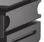
4 2 Overview of the RaceChip A A Digital User Interface for controlling the RaceChip B B +/- buttons for changing the mapping (see Fine tuning) C Power ON light; lights only when the vehicle ignition is on and power is being supplied to the RaceChip D Display showing mapping selected (see Fine tuning) C D E Slot for 360 fixing clips. F FCI plug for connecting to the vehicle s wiring E E F 4
5 3 Installation Step 1 of 7 - Preparation Before installing the RaceChip, please wait for your engine to cool down. Otherwise there is a risk of sustaining burns. 1 Open your vehicle s bonnet, and close and lock the doors. 2 Wait about 10 minutes before starting Step 2, as all current consumers must have switched themselves off. Generally speaking, you do not require special tools to perform the installation. If you need a tool, we will tell you when you get to the relevant step in these instructions. You will probably find wire cutters useful for clipping off the loose ends of cable ties. For cars with Keyless Go : after locking the car, place the key out of signal range (about 10 m from the car). If an alarm system is fitted: disable the alarm before starting installation. Some cars will not lock completely if the bonnet is open and electrical consumers are still active. If this is the case with your car, push the bonnet catch over manually, lock the car again and wait ca. 15 minutes. When you have finished the installation, do not forget to release the catch again by pulling the bonnet release lever. If you have any questions or difficulties during the installation, please refer to Trouble Shooting for hints and tips. Our Customer Service is of course always ready to help. See Contact for details. 5


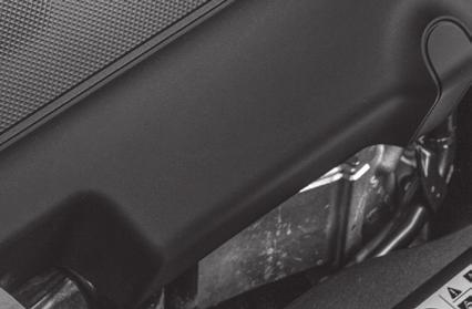


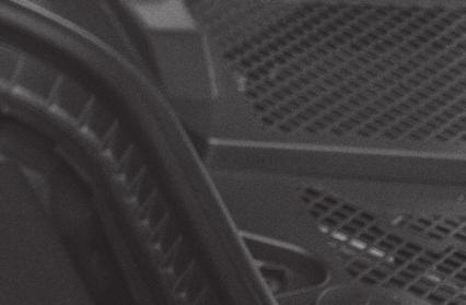
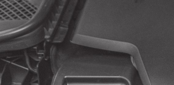
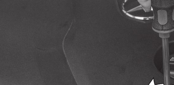
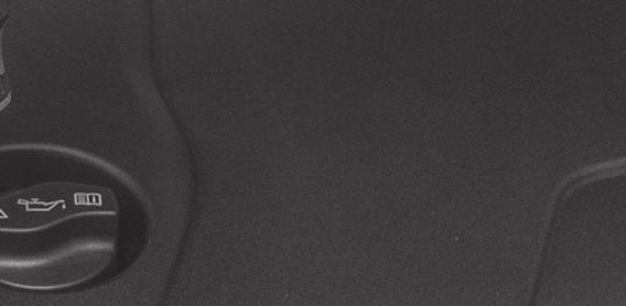


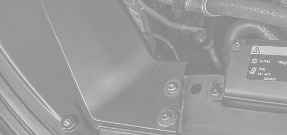
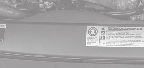
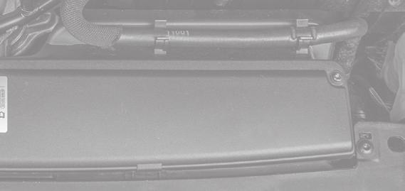
6 3 Installation Step 2 of 7 - Removing the engine cover The pictures on the following pages are for demonstration purposes only details may be in your car s engine bay. However, the installation process is identical. The engine cover is held in place by clips (A) or screws (B) A Remove the engine cover and place it next to the car. You may have to jiggle the cover slightly to release it from the holding clips B In some vehicles it is necessary to loosen one or more screws before you can remove the engine cover If there is no cover on your engine, you can proceed directly to step 3 6


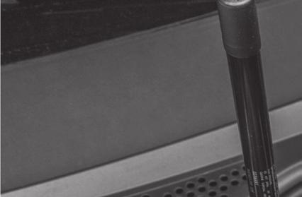
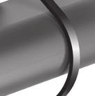
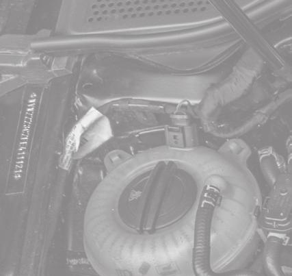
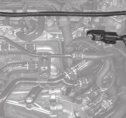
7 3 Installation Step 3 of 7 Connection to common rail sensor 1 Common rail connection First locate the common rail sensor connection in your engine bay. The common rail sensor connection is located either at one of the ends of or centrally on the common rail and can be clearly identified by the large union nut. The best way to find the common rail itself is by following the injection lines. These always lead directly from the injection system to the cylinders, i.e. they can be traced back from the engine block. Setup illustration Common rail connection Common rail connection A Cable with disconnected stock plug Cable from the RaceChip 7


 for")


8 3 Installation 2 Disconnect the plug from the common rail sensor If you experience difficulties disconnecting the common rail sensor, see Detaching the Connector Correctly (separate document) for assistance 3 Now connect the end of the RaceChip wiring harness marked A to the disconnected connector and the other end to the sensor Make sure that the plug s locking clip engages again. You should hear a sharp CLICK. 8


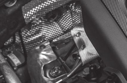
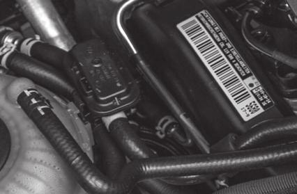
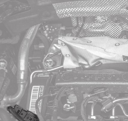
9 3 Installation Step 4 of 7 Connection to turbo boost pressure sensor 1 Turbo boost pressure sensor Once the connection to the common rail is complete, it is time to make the connection to the turbo boost pressure sensor. To begin, locate the turbo boost pressure sensor in your engine bay. Setup illustration Turbo boost pressure connection Turbo boost pressure sensor B Cable from the RaceChip Cable with disconnected stock connector 9


10 3 Installation 2 Disconnect the turbo boost pressure sensor If you experience difficulties disconnecting the turbo boost pressure sensor, see Detaching the Connector Correctly (separate document) for assistance 3 Now connect the end of the RaceChip wiring harness marked B to the disconnected connector and the other end to the sensor Make sure that the plug s locking clip engages again. You should hear a sharp CLICK. 10


11 3 Installation Step 5 of 7 Connecting the RaceChip and first function test 1 2 Disconnect the deactivation plug from the wiring harness Connect the RaceChip If the Digital User Interface lit up as soon as it was connected, this means that there was still power in the system during the installation. In some cases, this can lead to an error message during the first function test. Please refer to Trouble Shooting for a solution 3 Carrying out function test Position the RaceChip and the wiring harness safely in the engine bay. Do not fix anything in place yet. Switch the ignition on DO NOT start the engine Check for the following: - Control lights on the dashboard light up and go out as normal - The Power ON light on the Digital User Interface of your RaceChip lights up (see Overview of the RaceChip) If all the above happens, you can start the engine. It should start as normal and should react to the throttle when idling Switch off the engine and ignition If your car will not start as normal, please refer to Trouble Shooting for hints and tips Our Customer Service is of course always ready to help. See Contact for details 11


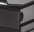


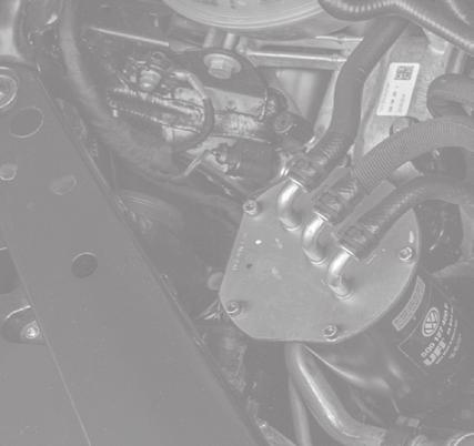


12 3 Installation Step 6 of 7 Fixing RaceChip and wiring harness RaceChip Wiring harness Before fixing the RaceChip in place in the engine bay, ensure that the wiring harness can also be routed and fixed securely without putting it under excessive tension. Use the 360 fixing clips included to fix the RaceChip and thread the cable ties through the fixing clips to hold the wiring harness in place * CLICK * If you need to remove the RaceChip at a later date, you can simply release the clips and do not have to cut any cable ties. 12


.")

 as this could result")


13 3 Installation Route the cable along a suitable path (for example, along existing wiring harness) and then fasten it using the supplied cable tie When selecting a fastening point, make sure that the RaceChip is protected from exposure to water, heat, and vibrations Do not wrap the RaceChip in an airtight bag as this can lead to a built up of condensation Do not route the cable in areas in your vehicle that become overly hot during operation (e.g. the exhaust system, turbocharger, etc.). Do not route the cable along movable parts Never fasten the cable onto hoses (e.g. a brake hose) as this could result in abrasion Step 7 of 7 - Completing the installation Re-attach the cover of your engine and close the bonnet. The installation process is now complete and your RaceChip is ready for use. Take your car for a test drive. If you have any questions, do not hesitate to contact our Customer Service department (see Contact for details) 13
14 4 Fine tuning The RaceChip has been calibrated specifically for the engine in your car, and further adjustment is generally not necessary in order to get the best performance. However, performance tolerances or the condition of the engine sometimes mean that Fine tuning is needed after installing the RaceChip. The Digital User Interface of the RaceChip (see Overview of the RaceChip) lets you carry out the Fine tuning yourself to get the best from your RaceChip-enhanced engine. Fine tuning may be necessary if the following occurs: A Engine idles more roughly than in stock tune. Engine runs roughly, knocks or pinks under load, or the engine warning light comes on. Mapping step -1 Mapping step +1 The Fine tuning mappings can be changed using the +/- buttons only when the ignition is switched on but without the engine running. Mapping 5 is the factory setting. First activate Mapping 1. Take your car for a test drive. If the engine performs as smoothly as you want, i.e. no hesitation or knocking, please activate Mapping 2 and go for another test drive. If the engine still performs as smoothly as you want, repeat the previous step. If the engine does not perform as smoothly as you want with one of the mappings, go back to the previous mapping this is the right one for your engine. If your engine does not run smoothly with any of the mappings or if the engine control light is permanently on after making all the adjustments (and after switching the ignition off and waiting 15 minutes), please contact our Customer Service (see Contact for details). 14
15 4 Fine tuning A Making the enhanced performance more noticeable If the driver does not experience the extra performance, it means the driver cannot feel the difference from stock tuning. Mapping step -1 Mapping step +1 The Fine tuning mappings can be changed using the +/- buttons only when the ignition is switched on but without the engine running. Mapping 5 is the factory setting. First activate Mapping 6. Take your car for a test drive. Activate Mapping 7 only if you do not experience the enhanced performance strongly enough. If the engine does not perform as smoothly as you want, activate the next mapping down the scale (e.g. from 6 to 5). Mapping 0 puts the engine into stock tune with the RaceChip installed. You can also use the deactivation plug to return you car to stock tune without having to remove the wiring harness. In order to use the deactivation plug, you need to remove the RaceChip from the wiring harness connector and replace it with the deactivation plug. Before replacing the RaceChip with the deactivation plug, first ensure that there is no residual charge in the car s electrics (see Step 1). 15
16 5 Trouble Shooting If the RaceChip does not function as it should, you can find some initial assistance here. If the suggestions here do not solve the problem, please contact our Customer Service (see Contact). Description of problem No extra performance or performance not noticeable enough I am not satisfied with the performance level of my vehicle. What to do You can find detailed instructions on how to make the extra performance more noticeable in Fine tuning (section B ). Knocking/ rattling The engine knocks or rattles (diesel engine) more under load. It runs less smoothly than in stock tune. If you have the impression that your engine knocks or rattles more than in stock tune, please take the car for a few test drives to be sure that your first impression was right. On the test drive, pay special attention to the engine s behaviour under load the RaceChip only works then. If your first impression was right, you can find detailed instructions on how to make the engine run smoothly again in Fine tuning (section A ). If the knocking/rattling is very noticeable, you can carry out the steps described in Fine tuning immediately. Jolting With the RaceChip installed, my car jolts, stutters or hesitates in situations where it did not before. You can find detailed instructions on how to make the engine run smoothly again in Fine tuning (section A ). If that does not cure the problem, please contact our Customer Service; if you can describe the circumstances when the problem occurs, our Customer Service can make further adjustments. Quality of gear shift reduced The shift behaviour and/or the shift quality has worsened since the installation of the RaceChip. The gearbox sometimes cannot seem to find the right gear. Using the Digital User Interface (see Overview of the RaceChip), select the next Fine tuning mapping down the scale. Repeat this procedure until you are happy with the gear shifting. If that does not cure the problem, please contact our Customer Service; if you can describe the circumstances when the problem occurs, our Customer Service can make further adjustments. 16
17 5 Trouble Shooting Description of problem Engine fault light or other warning light comes on and stays on after installing the RaceChip. A warning light on the dashboard comes on and stays on after installation of the RaceChip. What to do If a warning light (e.g engine fault light) comes on, it does not automatically mean something is wrong with the engine. The lamp can simply be a measure programmed by the manufacturer to protect the engine; it can be triggered if a cable is disconnected from a sensor when there was still power in the system, for instance. (An indication that this might be the case is if the Digital User Interface lit up as soon as it was connected to the car s electrics; it should only receive power when the ignition is switched on). Please follow the steps below carefully until you have found the cause of the warning lamp and fixed it. De-install the RaceChip wiring harness to the point that you can reconnect all the connections in your car as they were before you started installing the RaceChip. Lock the car and wait ca. 30 minutes before starting the engine. If the warning light still stays on, stopping and restarting the engine several times or waiting for even longer can sometimes help. If the warning lights have gone out, you can re-install the RaceChip. Make sure the ignition is off and wait at least 15 minutes before disconnecting the sensors. When the installation is complete, double check all the connections to ensure the connectors are joined correctly and tightly. Please connect the Deactivation plug to the wiring harness and start the engine again. If the warning lights do not come on, switch off the engine again and wait for 15 minutes. You can now replace the Deactivation plug with the RaceChip and start the engine again. If the warning lights come on again now, please contact our Customer Service (see Contact). Soot generation My car produces (more) soot since installing the RaceChip. You can find detailed instructions on how to make the engine run smoothly again in Fine tuning (section A ). The steps will also help stop the engine producing excess soot. 17
18 5 Trouble Shooting Description of problem Engine fault light comes on after a while and stays on After driving with the RaceChip (including acceleration) for while, the engine fault light comes on and stays on. What to do Please park your car and switch the engine off while leaving the ignition on. Activate Mapping 1 (see Fine tuning, section A ) and then turn the ignition off. Lock the car and wait ca. 30 minutes before starting the engine again. If the warning light does not come on again, you can follow the steps described in Fine tuning (section A ) to activate the right mapping. If the fault light is still on, please activate Mapping 0 or replace the RaceChip with the Deactivation plug (supplied). This returns your car to stock tuning. Lock the car and wait ca. 30 minutes before starting the engine again. Please contact our Customer Service (see Contact) and tell them what you see (warning is on/not on). The car does not start The car s ignition does not work after installing the RaceChip. Something probably went wrong during the installation procedure. Please follow the steps below to check that the RaceChip is installed correctly. De-install the RaceChip wiring harness the point that you can reconnect all the connections in your car as they were before you started installing the RaceChip. (You can leave the wiring harness in the engine bay; the important thing is that it is not connected to the vehicle electrics). Lock the car and wait ca. 30 minutes before trying to start the engine again. If the car starts, you can re-install the RaceChip. Make sure the ignition is switched off and wait at least 15 minutes before disconnecting the sensors in the engine bay. After installing the RaceChip, double check that all the connectors are correctly and firmly fixed. Go through all the steps described in Installation again. Finally, start the engine. If the car still does not start, please contact our Customer Service (see Contact). 18
19 5 Trouble Shooting Description of problem No noticeable fuel savings I do not notice any fuel savings What to do Make sure you are comparing before-and-after fuel consumption based on the vehicle s actual consumption on-board computers often display incorrect values. It is important that your driving style remains the same, i.e. you do not accelerate harder or drive fast more often than before. You will not see any fuel savings either if you often drive at or near maximum load you need to adopt an economical driving style at least some of the time in order to save fuel. If your driving style is at least partly economical and you still do not save fuel, please select the next Mapping up the scale via the Digital User Interface of the RaceChip (see Fine tuning, section B ). After selecting a new mapping, check the actual consumption to see if there has been any reduction. 19


20 6 Contact Our Customer Service is ready to help! Find out how to contact us at: Please have your customer details close by when you contact us. Follow us on: Legal notice RaceChip Chiptuning GmbH & Co. KG Ulmer Str Göppingen Germany Sales tax identification number: DE Registered at District Court of Ulm: HRA Tax number: 63079/11153 Personally liable partner: RaceChip Chiptuning Verwaltungs GmbH Chief executives: Dominic Ruopp, Dr. Daniel Appelhoff, Dirk Bongardt, Manuel Götz Head office: Ulmer Str. 123, Göppingen, Germany Registered at HRB District Court of Ulm: HRB Item number: EBA-ALLG-GTSBLACK-CR-K2-ENG-V1 20
PLEASE READ BEFORE STARTING INSTALLATION!
 PLEASE READ BEFORE STARTING INSTALLATION! User Manual Contents 1 Scope of delivery...3 2 Installation...4 3 Operation...11 4 Trouble Shooting...12 5 Contact...15 Overview and explanation of symbols Warnings
Installation Instructions
 This product has been designed and manufactured to work correctly with installation as described in these instructions. Failure to follow these instructions could result in damage to property, damage to
Installation Instructions
 This product has been designed and manufactured to work correctly with installation as described in these instructions. Failure to follow these instructions could result in damage to property, damage to
Installation Directions for FINGER STICK and Blocker Plate
 Installation Directions for FINGER STICK and Blocker Plate What is a Finger Stick? A Finger Stick is a simple circuit that modifies the MAF signal on LLY and LBZ engines (not LB7 engines) to expected levels
>> System CRD14-System LDK-18 /
 System CRD14-System LDK-18 / 10556218 ENG20006 Table of Contents Scope of delivery / Preliminary 3 General instructions 4 Installation principle 5 Changing Programs 6 Trouble shooting 7 Installation example
Installation Tips for your Remote Start system (for Toyota Camry & Prius C, ) Crimestopper RS0+ EVO-ALL T3468 rev#1.
 Crimestopper RS0+ EVO-ALL T3468 rev#1.") Installation Tips for your Remote Start system (for Toyota Camry & Prius C, 2012-2014) Crimestopper RS0+ EVO-ALL T3468 rev#1.1 1/22/2015 Thank you for purchasing your remote start from MyPushcart.com -
Installation Tips for your Remote Start system (for Toyota Camry & Prius C, 2012-2014) Crimestopper RS0+ EVO-ALL T3468 rev#1.1 1/22/2015 Thank you for purchasing your remote start from MyPushcart.com -
PART NUMBER: D APPLICATIONS:
 PART NUMBER: D440-0121 APPLICATIONS: 2017-19 F22/F23 230i & xdrive 2016-18 F30 330i & xdrive 2016-19 F31/F34 330i & xdrive 2017-19 F32/F33/F36 430i & xdrive 2017-19 G30 530i & xdrive 2018-19 G01 X3 30i
Installation Tips for your Remote Start system (for RS4LX>GMBP for GM vehicles)
") Installation Tips for your Remote Start system (for RS4LX>GMBP for GM vehicles) Thank you for purchasing your remote start from MyPushcart.com - an industry leader in providing remote starts to doit-yourself
Installation Tips for your Remote Start system (for RS4LX>GMBP for GM vehicles) Thank you for purchasing your remote start from MyPushcart.com - an industry leader in providing remote starts to doit-yourself
INSTALLATION MANUAL AP60B INSTALLATION MANUAL
 INSTALLATION MANUAL 2. TOOLS REQUIRED The following is a list of tools required to properly install the cruise control. While this unit may be installed without some of the tools listed, it is recommended
Ventilation System Before Starting
 How Long Should You Crank An Engine Ventilation System Before Starting Any electric start motor should be able to be started using a rope, (unless the motor Someone may have "worked' on it before and flopped
Single Barrel Shotgun HPFP Install Guide
 Single Barrel Shotgun HPFP Install Guide Thank you for purchasing the VTT Single Barrel Shotgun HPFP upgrade kit! PLEASE READ THE ENTIRE GUIDE BEFORE BEGINNING INSTALLATION! The first thing you should
INSTALLATION MANUAL. For: ACURA NSX
 INSTALLATION MANUAL For: ACURA NSX Package contents cable loom Electronics Bridge plug Installation manual Requested Tools Diagonal pliers small screwdriver T30 Torx Bit 1/4 or 3/8 ratchet 10mm Socket
PERFORMANCE UPGRADE? I CHOOSE RACECHIP!
 SIMPLY FASTER. PERFORMANCE UPGRADE? I CHOOSE RACECHIP! Nick Heidfeld has been brand ambassador for RaceChip Chiptuning since April 2017. He currently races in Formula E and was one of the most successful
TIP SHEET T2352, T3396. Installation Tips for RS1 + EVO-ALL 1-BUTTON REMOTE STARTER FOR: Acura RDX PUSH-TO-START / AUTOMATIC
 Installation Tips for RS1 + EVO-ALL 1-BUTTON REMOTE STARTER FOR: Acura RDX 2013-2015 PUSH-TO-START / AUTOMATIC TIP SHEET T2352, T3396 Thank you for purchasing your remote start from MyPushcart.com - an
CHIP V-CR CUSTOMER SERVICE CONTACT DETAILS CONTACT CUSTOMER SERCVICE. GENERAL INSTALALTION INSTRUCTIONS FOR ALL
 CUSTOMER SERVICE CONTACT DETAILS GENERAL INSTALALTION INSTRUCTIONS FOR ALL CHIP V-CR Common-rail system versions [1- and 2-channel tuning] CONTACT Küberl Tuning GmbH Endach 34, A-6330 Kufstein Telephone
Shotgun Single Barrel HPFP install guide
 Shotgun Single Barrel HPFP install guide Thank you for your purchase of the VTT Shotgun Single Barrel HPFP upgrade! First thing to do when you open your box is to make sure all parts are in their respective
Chiptuning CAR. Installation Instructions. Version 2 / Stand / English
 Chiptuning CAR System FSR14-System LLN6 / 10573532 ENG30033 Table of Contents Scope of delivery / Preliminary General instructions Installation principle Changing Programs Trouble shooting Installation
Installation Tips for your Remote Start/Keyless Entry (for Honda/Acura Vehicles) [EVO-ALL] v1.02 updated 9/13/2013
![Installation Tips for your Remote Start/Keyless Entry (for Honda/Acura Vehicles) [EVO-ALL] v1.02 updated 9/13/2013](/thumbs/87/96035180.jpg "Installation Tips for your Remote Start/Keyless Entry (for Honda/Acura Vehicles) [EVO-ALL] v1.02 updated 9/13/2013") Installation Tips for your Remote Start/Keyless Entry (for Honda/Acura Vehicles) [EVO-ALL] v1.02 updated 9/13/2013 Thank you for purchasing your remote start from MyPushcart.com - an industry leader in
Installation Tips for your Remote Start/Keyless Entry (for Honda/Acura Vehicles) [EVO-ALL] v1.02 updated 9/13/2013 Thank you for purchasing your remote start from MyPushcart.com - an industry leader in
LLTek Introduces PowerBox Chip-Tuning Technology
 LLTek Introduces PowerBox Chip-Tuning Technology Fast Do it Yourself Installation With Stealth Technology Applications: for gas turbo or supercharged cars for diesel, turbo diesel or supercharged diesel
Remote Start Kit for GM Installation RS1/3/4/7 + ADS-DL Tip Sheet
 Remote Start Kit for GM Installation RS1/3/4/7 + ADS-DL Tip Sheet rev 1.4 12/16/2013 Thank you for purchasing your remote start from MyPushcart.com - an industry leader in providing remote starts to do-it-yourself
High Idle Kit Dodge Cummins (24 valve) Dodge Cummins (with APPS on motor) PLEASE READ ALL INSTRUCTIONS BEFORE INSTALLATION
 Dodge Cummins (with APPS on motor) PLEASE READ ALL INSTRUCTIONS BEFORE INSTALLATION") U 6 May 2014 (1036620-27) 1998.5-2014 Dodge / GMC High Idle Kit (I-00321) 1 High Idle Kit 1036620 1998.5 2002 Dodge Cummins (24 valve) 2003-2004 Dodge Cummins (with APPS on motor) 1036621 2005-2006 Dodge
U 6 May 2014 (1036620-27) 1998.5-2014 Dodge / GMC High Idle Kit (I-00321) 1 High Idle Kit 1036620 1998.5 2002 Dodge Cummins (24 valve) 2003-2004 Dodge Cummins (with APPS on motor) 1036621 2005-2006 Dodge
An Actual Driving Lesson. Learning to drive a manual car
 An Actual Driving Lesson Learning to drive a manual car Where are the controls that I might have to use in my driving: Knowing where the controls are, and being able to locate and use them without looking
Throttle Sensitivity Booster
 U 1 New version allows for optional control switch. See page 4 for details. Throttle Sensitivity Booster Apps Booster 1057730 (Manual trans only) Vehicle / Year 1998.5-2003 Dodge Cummins DO NOT INSTALL
CAPTUREPRO USER GUIDE
 CAPTUREPRO USER GUIDE Updated: September 2015 Power12 and CapturePro 2013, 2014, 2015 by Power12 Company v1.1 Table of Contents CapturePro Purpose and Design... 3 Why was CapturePro developed?... 3 How
KENSUN HID AUTOMOTIVE HEAD LAMP CONVERSION KIT INSTALLATION MANUAL
 1 KENSUN HID AUTOMOTIVE HEAD LAMP CONVERSION KIT INSTALLATION MANUAL 2 CONTENTS A. Before Installing B. Installing the Bulbs C. Installing the Ballasts D. For Bi Xenon Only: Installing the Relay Harness
Troubleshooting of the LubeTech Grease System
 Troubleshooting of the LubeTech Grease System February 2009 The LubeTech grease system is designed to be a preventative maintenance system that will extend the life of your bearings that are connected
TIP SHEET. Installation Tips for your RS IB-MUX / PKUMUX (D) + SPDT T1205 v1.2 4/3/14. 1 P a g e
 + SPDT T1205 v1.2 4/3/14. 1 P a g e") Installation Tips for your RS-150 + IB-MUX / PKUMUX (D) + SPDT T1205 v1.2 4/3/14 TIP SHEET Thank you for purchasing your remote start from MyPushcart.com - an industry leader in providing remote starts
Installation Tips for your RS-150 + IB-MUX / PKUMUX (D) + SPDT T1205 v1.2 4/3/14 TIP SHEET Thank you for purchasing your remote start from MyPushcart.com - an industry leader in providing remote starts
Instant Chat off the main page of Or simply call our tech team at
 02-07 WRX/STI Air Oil Separator for Top Mounted Intercooler Setups 2013-02- 27 Thank you for purchasing this PERRIN product for your car! Installation of this product should only be performed by persons
Throttle Sensitivity Booster
 U 21 March 2018 1057730-1057737 Throttle Sensitivity Booster (I-00358) 1 DOWNLOAD COLOR INSTALL MANUALS AT dieselperformance.com New version allows for optional control switch. See page 4 for details.
Shotgun Double Barrel HPFP install guide
 Shotgun Double Barrel HPFP install guide Thank you for your purchase of the VTT Shotgun Double Barrel HPFP upgrade! First thing to do when you open your box is to make sure all parts are in their respective
Table of Contents. 4 Getting Started 4 About the Juice 5 Safety Terms 5 Product Registration 6 Important Notes 7 Truck Orientation
 Table of Contents 4 Getting Started 4 About the Juice 5 Safety Terms 5 Product Registration 6 Important Notes 7 Truck Orientation 8 Juice Installation 1999-2003 (7.3L) 8 Supplied Items & Required Tools
Chiptuning CAR. Installation Instructions. >> System FSR14-System LN6 / ENG Version 2 / Stand / English
 System FSR14-System LN6 / 10573554 ENG30060 Table of Contents Scope of delivery / Preliminary General instructions Installation principle Changing Programs Trouble shooting Installation example 3 4 5
Installation & Programming Manual. Quick Reference
 Installation & Programming Manual Getting Started Prepare door, per additional instructions (included) before installing unit. IMPORTANT: Read instructions completely before beginning installation. Refer
Installation Instructions For #64060 Striker I Power Module GMC/Chevrolet Duramax LB7 Diesel
 2501 Ludelle Street Fort Worth, Texas 76105 817-244-6212 Phone 817-244-4024 Fax 888-350-6588 Sales 800-423-9696 Tech E-mail: painless@painlessperformance.com Web: www.painlessperformance.com Installation
AFT mid drive kit Trouble shooting guide For 24v to 48V Kelly Controller KBS 48101L-L 100 A peak
 Date: 2016-13-1 AFT mid drive kit trouble shooting guide Rev 1.7 Page 1 of 17 AFT mid drive kit Trouble shooting guide For 24v to 48V Kelly Controller KBS 48101L-L 100 Table of Contents 1. Safety... 2
CHARGE TANK. Overview. Using The Charge Tank. User Guide
 Overview The Charge Tank effectively triples the on-board charging speed of 2015 and later Zero S, SR, DS and DSR motorcycles when used with level 2 charging stations on the J1772 standard. This dealer-installed
O2 Sensor Testing. If your engine has unexpectedly started to run poorly, an O2 Sensor Test should be performed.
 O2 Sensor Testing If your engine has unexpectedly started to run poorly, an O2 Sensor Test should be performed. IMPORTANT: Testing the O2 sensors using the procedures below REQUIRES that the engine will
BrakeAway Products Inc. wishes you many years of cramp free cruising, ENJOY and ride SAFELY!!!
 Congratulations on the purchase of your new BrakeAway Motorcycle Cruise Control. At BrakeAway Products, we are committed to your complete satisfaction. With proper installation, use, and periodic maintenance,
Introduction. Open Loop vs. Closed Loop. The Purpose of an O 2 Sensor Clamp
 Introduction This O 2 sensor clamp is designed for use with the Greddy emanage Ultimate engine control system. While these instructions are specific to the Mazda MX-5 Miata, the clamp will work on any
CHASSIS DYNAMICS TABLE OF CONTENTS A. DRIVER / CREW CHIEF COMMUNICATION I. CREW CHIEF COMMUNICATION RESPONSIBILITIES
 CHASSIS DYNAMICS TABLE OF CONTENTS A. Driver / Crew Chief Communication... 1 B. Breaking Down the Corner... 3 C. Making the Most of the Corner Breakdown Feedback... 4 D. Common Feedback Traps... 4 E. Adjustment
CAPTUREPRO USER GUIDE FOR TESLA MODEL S, MODEL X, AND MODEL 3. Updated: September Power12 and CapturePro by Power12 Company v1.
 CAPTUREPRO FOR TESLA MODEL S, MODEL X, AND MODEL 3 USER GUIDE Updated: September 2018 Power12 and CapturePro 2013 2018 by Power12 Company v1.2 Table of Contents CapturePro Purpose and Design... 3 Why was
Installation Instructions Console Megashifter
 Installation Instructions Console Megashifter 1968-1969 Camaro Part Number 81035 This B&M Megashifter is designed to fit in the console of a 1968-1969 Chevrolet Camaro. In 1968, these vehicles were equipped
Installation Tips for your Crimestopper/ProStart Remote Start system (for GM vehicles) v1.01 updated 2/27/2012
 v1.01 updated 2/27/2012") Installation Tips for your Crimestopper/ProStart Remote Start system (for GM vehicles) v1.01 updated 2/27/2012 Thank you for purchasing your remote start from MyPushcart.com - an industry leader in providing
Installation Tips for your Crimestopper/ProStart Remote Start system (for GM vehicles) v1.01 updated 2/27/2012 Thank you for purchasing your remote start from MyPushcart.com - an industry leader in providing
N55 Turbo upgrade install guide
 N55 Turbo upgrade install guide Thank you for your purchase of the VTT BMW N55 Stage 2 turbo charger upgrade! First thing to do when you open your box is to make sure all parts are in their respective
Smart Opener Retrofit by Richard Bevan (bimmerfest riku2)
") Smart Opener Retrofit by Richard Bevan (bimmerfest riku2) Document history V 1.0 02.04.2015 Document created. Introduction This document tells how to retrofit the smart opener to a 2011 BMW 5 series (F10).
Smart Opener Retrofit by Richard Bevan (bimmerfest riku2) Document history V 1.0 02.04.2015 Document created. Introduction This document tells how to retrofit the smart opener to a 2011 BMW 5 series (F10).
Please contact BrakeAway Products tech support for additional (503) or
 or") Congratulations on the purchase of your new BrakeAway Motorcycle Cruise Control. At BrakeAway Products, we are committed to your complete satisfaction. With proper installation, use, and periodic maintenance,
Congratulations on the purchase of your new BrakeAway Motorcycle Cruise Control. At BrakeAway Products, we are committed to your complete satisfaction. With proper installation, use, and periodic maintenance,
Installation Instructions QUICKSILVER CONSOLE SHIFTER Fits: Chevelle / El Camino
 WORK SAFELY! For maximum safety, perform this installation on a clean, level surface and with the engine turned off. Place blocks or wedges in front of and behind both rear wheels to prevent movement in
EBIKE DIAGNOSIS FLOWS
 EBIKE DIAGSIS FLOWS 1 SUMMARY Check Tool Instructions 2 Display and Controller check tool 3 Display Holder check tool 7 Motor check tool 8 Battery check tool 9 Torque Sensor check tool 12 Customized controller
Installation Tips for your GMDLBP + Excalibur Remote Start system (for GM vehicles) v1.01 updated 10/09/13
 v1.01 updated 10/09/13") Installation Tips for your GMDLBP + Excalibur Remote Start system (for GM vehicles) v1.01 updated 10/09/13 Thank you for purchasing your remote start from MyPushcart.com - an industry leader in providing
Installation Tips for your GMDLBP + Excalibur Remote Start system (for GM vehicles) v1.01 updated 10/09/13 Thank you for purchasing your remote start from MyPushcart.com - an industry leader in providing
Superior Wheel Installation Guide (No Turbo removal)
") Superior Wheel Installation Guide (No Turbo removal) This is the process used to install the Turbo Wheel without having to remove the Turbo from your Engine. It should take a maximum of 5 hours. Tools:
Superior Wheel Installation Guide (No Turbo removal) This is the process used to install the Turbo Wheel without having to remove the Turbo from your Engine. It should take a maximum of 5 hours. Tools:
Installation Instructions Jeep CJ-7
 Retrofit Steering Column Installation Instructions 1976-86 Jeep CJ-7 For Part # s 1520800010, 152800020, 1520800051 www.ididitinc.com 610 S. Maumee St., Tecumseh, MI 49286 (517) 424-0577 (517) 424-7293
EVAP system, servicing
 Page 1 of 65 20-130 EVAP system, servicing EVAP system components 1 - Cap nut 10 Nm 2 - Cover 3 - Stud For EVAP canister 15 Nm 4 - Sealing piece 5 - Bleed line To EVAP canister purge regulator valve -
Depress each tab as you pull the bezel off. The bezels are tight. L.H. shown.
 2013-2014 Ford Mustang V6 & Boss 302 Lower Valance Fog Light Kit Parts List: Quantity: Tool List: Fog light & bulb with bracket 2 Flat head & Phillips screwdriver Black bezels 2 Ratchet & Socket set OR
TIP SHEET T0937. Installation Tips For RS00/PS00 + ADS-TBSL-PL + SPDT
 Installation Tips For RS00/PS00 + ADS-TBSL-PL + SPDT TIP SHEET T0937 Thank you for purchasing your remote start from MyPushcart.com - an industry leader in providing remote starts to do-it-yourself installers
Stratified Aux fuel system ecoboost 2.0
 Stratified Aux fuel system ecoboost 2.0 Additional Fuel Injection System Installation and User Guide Stratified Aux Fuel System Installation and User Guide -1-0204-0021.1 Thank you and congratulations
TRW Commercial Steering Torque Overlay Diagnostic Tool
 TRW Commercial Steering Torque Overlay Diagnostic Tool Ver. 1.0.0.6 September 16, 2014 Page 1 of 13 The TRW Torque Overlay Diagnostic Tool is intended to assist a service technician answer the following
INSTALLATION INSTRUCTIONS
 INSTALLATION INSTRUCTIONS Accessory Application Publications No. All 12035 SYSTEM 2012 RIDGELINE Issue Date NOV 2011 PARTS LIST Security System Attachment Kit: P/N 08E55-SJC-101 Flange bolt Unit bracket
LANCER FOG LAMP KIT MZ380479EX (for RHD) INSTALLATION AND HANDLING INSTRUCTIONS
 INSTALLATION AND HANDLING INSTRUCTIONS") LANCER FOG LAMP KIT MZ380479EX (for RHD) INSTALLATION AND HANDLING INSTRUCTIONS Fog lamp Thank you for purchasing the Mitsubishi Genuine Accessory. To install and use the product correctly with proper
LANCER FOG LAMP KIT MZ380479EX (for RHD) INSTALLATION AND HANDLING INSTRUCTIONS Fog lamp Thank you for purchasing the Mitsubishi Genuine Accessory. To install and use the product correctly with proper
Table Of Contents TABLE OF CONTENTS INTRODUCTION INSTALLATION OPERATING INSTRUCTIONS APPENDIX ABOUT THE JUICE... 3 SAFETY TERMS...3 INTRODUCTION...
 Ford Juice installation Instructions **read important safety information in this manual** TABLE OF CONTENTS F o r d J u i c e Table Of Contents ABOUT THE JUICE... 3 SAFETY TERMS...3 INTRODUCTION... 3 PRODUCT
CBR250 Fitment Guide
 CBR250 Fitment Guide 35W Bulbs Before 60W GT150 Power2Night Bulbs The mod is designed to allow the headlights to be upgraded from the 35W bulbs to 60W bulbs. Normally, this would cause flat battery trouble
Installation instructions
 Installation instructions Akrapovič Exhaust System: Sound Kit for the Audi R8 5.2 FSI ENGLISH Version 1.0 04/2016 Installation instructions Akrapovič Exhaust System: Sound Kit for the Audi R8 5.2 FSI
Installation Tips for RS1 + EVO-RIDE + SPDT. *(reglar key, automatic transmission vehicles ONLY)*
*") Installation Tips for RS1 + EVO-RIDE + SPDT TIP SHEET T1235 *(reglar key, automatic transmission vehicles ONLY)* Thank you for purchasing your remote start from MyPushcart.com - an industry leader in providing
Installation Tips for RS1 + EVO-RIDE + SPDT TIP SHEET T1235 *(reglar key, automatic transmission vehicles ONLY)* Thank you for purchasing your remote start from MyPushcart.com - an industry leader in providing
INSTALLATION INSTRUCTIONS CATCH CAN KIT
 INSTALLATION INSTRUCTIONS CATCH CAN KIT FORD FIESTA ST Document: 19-0175 Support: info@radiumauto.com STEPS 1-14 COVER THE PCV SIDE CATCH CAN KIT (P/N: 20-0377) STEPS 15-31 COVER THE CRANKCASE CATCH CAN
Throttle Cable Pull - Patent Pending By: NetGain Controls, Inc.
 Throttle Cable Pull - Patent Pending By: NetGain Controls, Inc. Powering the future! Installation Guide 2011 All Rights Reserved NetGain Controls, Inc. 1 of 8 Introduction Thank you for purchasing a NetGain
Installation Instructions Diesel Nitrous System (#82028)
") Installation Instructions Diesel Nitrous System (#82028) Thank you for choosing ZEX. If at any time you have questions regarding this or any of our products, please call our Nitrous Help support line at
Installation Instructions Diesel Nitrous System (#82028) Thank you for choosing ZEX. If at any time you have questions regarding this or any of our products, please call our Nitrous Help support line at
Step 1 Wiring your remote start. Installation Tips for your Remote Start system (for GM vehicles) V3.3 revised 9/12/2013
 V3.3 revised 9/12/2013") Installation Tips for your Remote Start system (for GM vehicles) V3.3 revised 9/12/2013 Thank you for purchasing your remote start from MyPushcart.com - an industry leader in providing remote starts to
Installation Tips for your Remote Start system (for GM vehicles) V3.3 revised 9/12/2013 Thank you for purchasing your remote start from MyPushcart.com - an industry leader in providing remote starts to
INSTRUCTIONS. #82028 Diesel Nitrous System. Thank you for choosing ZEX products; we are proud to be your manufacturer of choice.
 1 INSTRUCTIONS #82028 Diesel Nitrous System Thank you for choosing ZEX products; we are proud to be your manufacturer of choice. Why our nitrous system is better: 2 Performance enthusiasts know the potential
Retro it Steering Column
 Retro it Steering Column INSTALLATION INSTRUCTIONS for 1976-86 CJ5 & CJ7 FOR PART NUMBER S: 1520800010, 1520800020, 1520800051, 1526800010, 1526800020, 1526800051 S I NCE 1986 Instruction # 8000000010
installation instructions
 The product described in the guidance was developed, manufactured and controlled considering the necessary safety reguirements. The product must be installed properly to ensure a proper function and avoid
TRAIL-Control - Manufacturer -
 Installation and Operating Instructions TRAIL-Control - Manufacturer - Release 03-2001 Müller Elektronik GmbH & Co. KG Franz-Kleine-Str. 18 33154 Salzkotten Datei: 302901-02_E(ME015488)_PDF.DOC Contents
Installation Tips for your Excalibur Remote Start (for Honda and Acura Vehicles) rev 11/28/2012
 rev 11/28/2012") Installation Tips for your Excalibur Remote Start (for Honda and Acura Vehicles) rev 11/28/2012 Thank you for purchasing your remote start from MyPushcart.com - an industry leader in providing remote starts
Installation Tips for your Excalibur Remote Start (for Honda and Acura Vehicles) rev 11/28/2012 Thank you for purchasing your remote start from MyPushcart.com - an industry leader in providing remote starts
EFI Harley Davidson 1340 EVO
 Floppy Disc Request Form If you do not have a CD-Rom drive and would like to receive the program and the alternate maps for your model on a 3 1/2 floppy disc, please fax this form to Dynojet at 1-702-399-1431
TRW Commercial Steering Diagnostic Tool
 TRW Commercial Steering Diagnostic Tool Ver. 1.0.1.3 Valid software versions: AP0004-I AP0004-M AP0004-N AP0004-R AP0006-A AP0006-B AP0006-E AP0006-F AP0006-G AP9001-A May 23, 2016 Page 1 of 14 The TRW
1 Function Scope of Delivery Mounting Electrical Connections Initial Setup Troubleshooting...
 Elektronik Sachse MHP GmbH & Co. KG Installation Manual Digital Ignition ZDG 3.23 (Ducati Mille) Item: Z73 version: f4feb00 Contents 1 Function.......................................................................
Stand Alone Fog Lights Installation Instructions
 Tools Required: 1. Trim Removal tool or protected flat screwdriver 2. #2 Phillips Screwdriver 3. 10mm socket 4. 10mm wrench 5. 8mm or 5/16 socket 6. Adjustable Pliers 7. Electrical Tape WARNING!!! Disconnect
Installation instructions
 The product described in the guidance was developed, manufactured and controlled considering the necessary safety reguirements. The product must be installed properly to ensure a proper function and avoid
1 of 2 9/4/ :27 AM
 Ford Mustang IAC IAB - Solving your idle problems http://www.muscularmustangs.com/iac.php 1 of 2 9/4/2010 10:27 AM Solving idle problems part 1 - Cleaning your IAC Does your idle rise and fall over and
Tecomotive - tinycwa User Manual
 Tecomotive - tinycwa User Manual Overview Contents - tinycwa controller - Fuse holder - Fuses (15A/30A) - Connector 8 pin (controller) - Connector 4 pin (water pump) - Connector 2 pin (temperature sensor)
READ AND FOLLOW ALL SAFETY INSTRUCTIONS SAVE THESE INSTRUCTIONS
 7.5 Swift Lock Ready Shape Tree (Patent Pending) Instructions IMPORTANT SAFETY INSTRUCTIONS When using electrical products, basic precautions should always be followed including the following: READ AND
Installation Instructions For #64066 Striker I Power Module Ford Powerstroke 6.0L Diesel Copyright
 Installation Instructions For #64066 Striker I Power Module 2003-2006 Ford Powerstroke 6.0L Diesel 2 nd Edition August 2007 Copyright 2006 by Perfect Performance Products, LLC 2501 Ludelle Street Fort
INSTALLATION MANUAL. For: LAMBORGHINI URUS
 INSTALLATION MANUAL For: LAMBORGHINI URUS Package contents cable loom Electronics Bridge plug Installation manual Requested Tools side cutter small screwdriver ratch with 13 nut Important! To be able to
QUICK START GUIDE 199R10546
 QUICK START GUIDE 199R10546 1.0 Overview This contains detailed information on how to use Holley EFI software and perform tuning that is included within the software itself. Once you load the software,
INSTRUCTIONS. #82044 Race Diesel Nitrous System
 INSTRUCTIONS #82044 Race Diesel Nitrous System Thank you for choosing ZEX products; we are proud to be your manufacturer of choice. Kit Parts List Description Qty. Description Qty. Nitrous Solenoid 2.088
feature 10 the bimmer pub
 feature 10 the bimmer pub BMW E90 Steering Angle Sensor Diagnosis A pattern failure may indeed point you to a bad component, but when the part is expensive you want to be very sure it s the culprit before
DODGE CUMMINS 24V ISB
 19 November 2009 1998-1999 Dodge Cummins OEM Bypass Lift Pump Kit # 1050230-1 - 1998-99 DODGE CUMMINS 24V ISB OEM BYPASS LIFT PUMP KIT I n s t a l l a t i o n I n s t r u c t i o n s Part# 1050230 PLEASE
Installation Instructions for the Plug & Play Remote Start Package (EVOCHR5)
") T6018 v1.1 02/2013 Installation Instructions for the Plug & Play Remote Start Package (EVOCHR5) For DODGE Nitro 2007-2011 Review the remote start installation manual for safety instructions! Overview Your
T6018 v1.1 02/2013 Installation Instructions for the Plug & Play Remote Start Package (EVOCHR5) For DODGE Nitro 2007-2011 Review the remote start installation manual for safety instructions! Overview Your
Last Revision: 30JN THRU 1979 C3 CORVETTE STANDARD (NON-ADJUSTABLE) STEERING COLUMN DISASSEMBLY & REPAIR INSTRUCTIONS PAPER #2
 STEERING COLUMN DISASSEMBLY & REPAIR INSTRUCTIONS PAPER #2") Last Revision: 30JN2007 1969 THRU 1979 C3 CORVETTE STANDARD (NON-ADJUSTABLE) STEERING COLUMN DISASSEMBLY & REPAIR INSTRUCTIONS PAPER #2 Disassembly and Repair Instructions Addressed in this Paper Degree
Last Revision: 30JN2007 1969 THRU 1979 C3 CORVETTE STANDARD (NON-ADJUSTABLE) STEERING COLUMN DISASSEMBLY & REPAIR INSTRUCTIONS PAPER #2 Disassembly and Repair Instructions Addressed in this Paper Degree
Eurocompulsion Camshaft Installation
 Eurocompulsion Camshaft Installation Introduction, please read. The purpose of this article is too assist our customers with installation of a performance camshaft in the Fiat Multiair 1.4 Turbo. The operation
Mexican Beetle 1600i. Fuel Injection System. Ignition Timing
 Mexican Beetle 1600i Fuel Injection System Ignition Timing Version 1.00 Phil Ade 2005 1 Table of Contents 1.0 Introduction 3 1.1 Tools Required 3 1.2 Prerequisites 3 2.0 Setting the Timing on a 1600i Engine
TCI Trans-Scat
 Page 1 of 5 Return to Instruction Sheet index TCI 350000 Trans-Scat Installation Instructions For TURBO HYDRAMATIC 350 This kit will allow you to reprogram your transmission to meet your driving needs
Installation Tips - (Crimestopper RS1/RS2) & (Fortin EVO-ALL 5): *regular key & automatic transmission only*
 & (Fortin EVO-ALL 5): *regular key & automatic transmission only*") Installation Tips - (Crimestopper RS1/RS2) & (Fortin EVO-ALL 5): TIP SHEET T3385f, T3413f *regular key & automatic transmission only* Thank you for purchasing your remote start from MyPushcart.com - an
Installation Tips - (Crimestopper RS1/RS2) & (Fortin EVO-ALL 5): TIP SHEET T3385f, T3413f *regular key & automatic transmission only* Thank you for purchasing your remote start from MyPushcart.com - an
3.4L V6 SUPERCHARGER 7 TH INJECTOR KIT
 Part Number: 00602-17620-260 00602-17620-261 00602-17620-263 00602-17620-264 00602-17620-274 00602-17620-275 00602-17620-276 Section I Installation Preparation Kit Contents Item # Quantity Reqd. Description
Installation Instructions for the Plug & Play Remote Start Package (EVOCHR4)
") T6002 v1.1 02/2013 Installation Instructions for the Plug & Play Remote Start Package (EVOCHR4) For CHRYSLER Town & Country 2008-2012 Review the remote start installation manual for safety instructions!
T6002 v1.1 02/2013 Installation Instructions for the Plug & Play Remote Start Package (EVOCHR4) For CHRYSLER Town & Country 2008-2012 Review the remote start installation manual for safety instructions!
ProRacing ChipBox Digital PD2 Certificate IPC: 7711/21, IEC:
 ProRacing Chipox Digital PD2 Certificate IPC: 7711/21, IEC: 61340-4-1 Table of Contents. 1. ProRacing Chip ox Digital PD2... 3 2. Set contains... 3 3. Principle of operation... 4 4. Pro Power Increase
Installation Tips for your Remote Start/Keyless Entry (for Ford Vehicles) v3.3 Updated 1/13/2013
 v3.3 Updated 1/13/2013") Installation Tips for your Remote Start/Keyless Entry (for Ford Vehicles) v3.3 Updated 1/13/2013 Thank you for purchasing your remote start from MyPushcart.com - an industry leader in providing remote
Installation Tips for your Remote Start/Keyless Entry (for Ford Vehicles) v3.3 Updated 1/13/2013 Thank you for purchasing your remote start from MyPushcart.com - an industry leader in providing remote
Disco 3 Clock Spring / Rotary Coupler replacement
 Disco 3 Clock Spring / Rotary Coupler replacement I recently had to change my Clock spring and thought some folks may find it helpful to see what it entailed. I did lots of reading around but couldn t
USER MANUAL PRODUCT CODE: WC CareCo (UK) Ltd, Hubert Road, Brentwood, Essex, CM14 4JE PAGE 1
 Ltd, Hubert Road, Brentwood, Essex, CM14 4JE PAGE 1") by USER MANUAL PRODUCT CODE: WC01059 CareCo (UK) Ltd, Hubert Road, Brentwood, Essex, CM14 4JE PAGE 1 CONTENTS 1. INTRODUCTION 2. IDENTIFICATION OF PARTS 3. SAFETY REGULATIONS 4. SAFETY WARNINGS 5. USER
by USER MANUAL PRODUCT CODE: WC01059 CareCo (UK) Ltd, Hubert Road, Brentwood, Essex, CM14 4JE PAGE 1 CONTENTS 1. INTRODUCTION 2. IDENTIFICATION OF PARTS 3. SAFETY REGULATIONS 4. SAFETY WARNINGS 5. USER
Peugeot 106 Citroen Saxo Gear Linkage Push Rods 3pc kit with grease seals x 2452/e1 Repair Fix Kit Instruction Install Guide
 Peugeot 106 Citroen Saxo Gear Linkage Push Rods 3pc kit with grease seals 245283 + 2 x 2452/e1 Repair Fix Kit Instruction Install Guide by x8rltd on August 6, 2015 Intro: Peugeot 106 Citroen Saxo Gear
This is a guide to assist you adjust the valve clearance on a 2l V6 MIVEC engine found in a Mitsubishi FTO GPX
 Adjusting the valve clearance on a 2L V6 FTO engine This is a guide to assist you adjust the valve clearance on a 2l V6 MIVEC engine found in a Mitsubishi FTO GPX Disclaimer: This guide is to assist you
Installation Tips for your Remote Start w/ Keyless Entry (Toyota Vehicles) v3.2 Updated 3/14/13
 v3.2 Updated 3/14/13") Installation Tips for your Remote Start w/ Keyless Entry (Toyota Vehicles) v3.2 Updated 3/14/13 Thank you for purchasing your remote start from MyPushcart.com an industry leader in providing remote starts
Installation Tips for your Remote Start w/ Keyless Entry (Toyota Vehicles) v3.2 Updated 3/14/13 Thank you for purchasing your remote start from MyPushcart.com an industry leader in providing remote starts