Battery Chargers - Phase Three Series
|
|
|
- Allyson Webster
- 5 years ago
- Views:
Transcription


1 shoes Battery Chargers DC Converters Inverters Power Supplies Power Stabilizers Inter rs DC Power Conditioners Electrical Panels Meters Digital Instruments Installation Acces 09/10


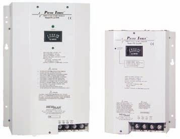
2 Battery Chargers - Phase Three Series Three Stage Smart Chargers Phase Three Smart battery charging technology is now available in a wide range of power levels, allowing you to select the right size, features and flexibility you require for virtually any application from small recreational craft to large live-aboards, workboats and other commercial vessels. These chargers interact with batteries to put them through the optimum three stage charge process which provides for fastest recovery and ideal conditioning, maximizing battery performance and extending battery life. A selector switch adjusts output voltage to adapt for gel-cell/flooded lead-acid/agm battery types. An optional temperature compensation sensor also adjusts output for ideal voltage based on changes in the batteries' ambient temperature. All models are housed in a rugged stainless steel case with a durable white powder coat finish, and the internal circuitry is polyurethane coated for maximum corrosion resistance. Features Smart circuitry provides three stage charging bulk, absorption, float. Wide model range covers battery system ratings from amp-hours Gel-Cell/Flooded Lead-acid/AGM battery type switch selects optimum charge/float voltages. Multiple isolated output banks; ammeter indicates total output current. (except PT-7) Optional sensor adjusts output voltage based on battery temperature. (except PT-7) Current limiting-prevents damage from overloading. Charger status clearly displayed with L.E.D. and/or audible indicators or optional remote panel. Use as a power supply; can power loads without a battery in line. Built to last rugged stainless steel case with a durable white powder coat finish with an optional drip shield and marinized internal circuitry. Numerous Safety and EMC Compliances Two year parts and labor warranty Models 12 Volt 24 Volt 32 Volt PT-7 PT-24-8W PT-32-25W PT-14W PT-24-13W PT-25W PT-24-20W PT-40W PT-24-45U PT-80 PT-24-60W PT-24-95U See next page for detailed specifications. Optional Accessories Remote Indicator Panel, Model: RP (Not available for all models - refer to Specifications on following page) DC Energy Monitor, reads Volts, Amps, Amp Hours (See page 20 for details) Temperature Compensation Sensor, Model: TCS-12/24 shown (see next page for applicable sensor depending on charger model) Phase Three Monitor/Control Unit For ABS Installation This unit, when used in conjunction with certain PT Chargers* creates a system which is fully compliant with American Bureau of Shipping (ABS) Battery Charging standards for commercial installations * For use with all models except PT-7, PT-24-60W, PT-24-95U, and PT Newport Beach, CA USA Incorporates Digital readout of float voltage to 1/10th volt Output float voltage adjustment pot; permits fine tuning from -4% to +5% AC circuit breaker; provides overcur rent protection and manual disconnect AC power ON indicator light 10 wiring harness for easy connection of PT Series charger Model: PT-MCU Size (HxWxD): 8.7 x4.6 x5.5 Weight: 3.5 lbs
3 MODEL: PT-88 INPUT: V DC. 60 HZ 13A, 1000 WATTS OUTPUT: 12VDC 55A CONTINUOUS 3 BANKS BATTERY 6 CELL LEAD ACID OR TYPE: GELL CELL AMP HOURS PROTECTION INPUT FUSE 15A F/O (REPLACE WITH LIKE FUSE) SELF-LIMITING HIGH RATE TIME OUT CIRCUIT TEMPERATUTER COMPENSATION AUTOMATIC RESETTING THERMAL PROTECTION IGNITION PROTECTED PER U.S.C.G.STD FORCED AIR COOLING RECERSE POLARITY TO REDUCE THE RISK OF ELECTRIC SHOCK DO NOT EXPOSE TO RAIN OR SPRAY, DISCONNECT POWER BEFORE OPENING COVER NEWPORT BEACH, CA USA TEL: (714) FAX: (714) FALIURE TO OBSERVE CORRECT POLARITY MAY CAUSE SEVERE DAMAGE Battery Chargers - Phase Three Series Specifications 12 Volt Models 24 Volt Models 32 Volt PT-7 PT-14W PT-25W PT-40W PT-80 PT-24-8W PT-24-13W PT-24-20W PT-24-45U PT-24-60W PT-24-95U PT-32-25W Input VAC or or or or or (50-60 Hz.) Input Full 115 VAC NA VAC N/A P.F. Rating >.65.93@230V @230V.93@230V @230V.7.95@230V.7.98@115V.98@115V.98@115V.98@115V.98@115V Max Output Amps Output Banks Battery Capacity (Amp-Hours) Operating Temp. T-1 T-2 T-4 T-5 T-7 T-2 T-3 T-5 T-8 T-6 T-8 T-6 Rating Reference Case Size Ref. A-1 A-2 A-2 A-3 A-5 A-2 A-2 A-3 A-5 A-6 A-6 A-4 Weight; Lbs./Kg. 3.2/1.5 8/4 8.2/4 12/6 15.2/7 8/4 8.2/4 12/6 12.2/6 24.1/ / /6 Optional Temp. Sensor Model N/A TCS-12/24 TCS-12/24 TCS-12/24 TCS-12/24 TCS-12/24 TCS-12/24 TCS-12/24 TCS-12/24 TP TCS-12/24 TP Remote Panel Model N/A RP RP RP RP RP RP RP RP N/A RP N/A Equalize Option No Yes Yes Yes Yes Yes Yes Yes Yes No Yes No Output Indicator Ref. M-1 M-3 M-3 M-3 M-3 M-3 M-3 M-3 M-3 M-2 M-3 M-2 Compliance Ref. CG, CE CG, CE CG CG, CE CG, CE CG CG, EN, CE EN, CE EN, CE EN, CE CE CE Case Size: D W CONNECT CHARGER LEADS DIRECTLY TO BATTERY BAT.1 BAT. 2 BAT.3 (-) COMM. H Temperature Rating References: T-1-10 C to +45 C; Derate linearly from 0 C to -10 C T-2-10 C to +60 C; Derate linearly from 40 C to 60 C T-3-10 C to +60 C; Derate linearly from 50 C to 60 C T-4-10 C to +60 C; Derate linearly from 40 C to 60 C T-5-40 C to +60 C; Derate linearly from 50 C to 60 C T-6-20 C to +50 C; Full output T-7-20 C to +70 C; Derate linearly from 45 C to 70 C T-8-20 C to +70 C; Derate linearly from 50 C to 70 C Temperature Compensation: - 5 mv per cell per C. Sensor supplied with 25' cable (40 cable optional) and plug-in connector Protection (all models): Input/Output Fuses, Current Limiting, Thermal Protection, Forced Air Cooling, Drip Shield Newport Beach, CA USA Inches Centimeters Ref H W D H W D A A A * * 35.2* * A A A 35 A A A B B 37.6 B B A C C 44.5 C C * Add.75 (1.9 cm) to height and 1.35 (3.4 cm) to depth A Add 1.27 (3.2 cm) to height and 1.1 (2.8 cm) to depth B Add 1 (2.54 cm) to height and.5 (1.27 cm) to depth C Add 2 (5.08 cm) to height and 1 (2.54 cm) to depth Compliance References*: See matrix for applicable models CG USCG CFR (Ignition protected) EN EN , EN Typical Charge Curve % OF CHARGER OUTPUT (AMPS) 100% BATTERY VOLTAGE AMPS VOLTAGE TIME CE Carries the CE Mark * Numerous other Safety and EMC compliances may also apply. Contact factory if further compliance information is required. Output Indicator References: M-1 Charge/Float L.E.D. M-2 Total output ammeter and charger status L.E.D. s/alarms M-3 Total output ammeter and power-on L.E.D. BULK ABSORPTION FLOAT MAINTENANCE MODE Nominal Output Voltages at Gel/Flooded Switch Settings (without Temperature Compensation option installed or at 22.2 C (72 F) with Temperature Compensation option installed.) 12 Volt Models 24 Volt Models 32 Volt Model Charge Float Charge Float Charge Float 50 % amp 50 % amp 50 % amp load Gel-Cell 14.0 VDC 13.6 VDC 28.0 VDC 27.2 VDC Flooded/AGM 14.2 VDC 13.4 VDC 28.4 VDC 26.8 VDC Remote Panel, Model RP: LED's indicate charger output stage. Manual reset button reinitializes three stage charge cycle. Supplied with 25' cable and plug-in connector. Panel dimensions: 3" H x 4.75" W *

4 Battery Chargers - Phase Three Modular A Battery Charging System with Redundant, Easily Replaced Charge Modules Providing High Reliability and Serviceability Reliability Redundant, independent, charger modules increase reliability a malfunction of one does not disable the charging system; remaining modules continue to operate. Serviceability Module change-out takes only minutes, while the system continues to operate Technical personnel not required No need to remove the charger case from the boat or disconnect any wiring No inconvenience of power interruption to the boat Features Three stage smart charging; bulk, absorption, float Battery type selector switch; gel-cell, lead-acid, AGM Temperature compensated output option Numerous diagnostic and system status indicators 12 Volt; amps or 24 Volt; amps Universal input of VAC, Hz. can be used anywhere in the world Powder coated stainless steel case The Phase Three Modular (PTM) Concept Super yachts and commercial vessels have complex electrical systems that support equipment essential to safe operation. These boats are frequently in transit or in remote locations where repair/service is not readily available. Down-time can be very costly and severely impact sailing schedules. Recognizing that all equipment has a finite service life and random component failure can occur at any time, system reliability can be improved by reducing the number of single points of failure, thus diminishing the impact of a solitary fault on the overall system. The PTM series applies this faulttolerant concept to battery chargers, by using multiple independent charger modules within the unit. The PTM consists of a case which serves as connection point to AC input and battery bank output, as well as three front-facing power bays, each accommodating a 550 watt charger module which slides and locks in place. If a module fault occurs, a front panel indicator is activated and the system continues operating. Captains and owners will appreciate this system approach to reliability. A dead charger and dead batteries can disable a vessel, but with the PTM redundant charging system a fault in one of the modules is easily identified and it can be quickly replaced with an on-hand spare or an exchange unit from the factory, while the charging system continues to operate. 4 Newport Beach, CA USA

5 Battery Chargers - Phase Three Modular The Phase Three Modular (PTM) Series is a battery charging system consisting of a wall mount case, which serves as a connection point for AC input and battery bank output that accommodate up to three charging modules which slide and lock into front access power bays. Its redundant charger modules increase reliability, as the system remains operational in the event of a charger module fault. The system is easily and quickly restored to full output by simple module replacement. The system features three stage charging for rapid recharge and optimal battery life. See pages 2 & 3 for a complete description of the three stage charging process. Specifications System Modules Max Output Max Input Amps Model Installed* 115/230 VAC PTMS V 18/9 PTMS V 18/9 General System Specifications Input Voltage/Frequency: VAC, Hz, single phase; derate linearly from 100% 105 VAC to 80% 90 VAC Power Factor: Efficiency: 85% typical Nominal Charge/Float Voltages: Refer to chart on page 3 Temperature Compensation (Option): - 5 mv per cell per C (typical) Temperature Rating: 0-60 C; derate linearly from 100% 50 C to 80% 60 C Recommended Battery Type/Capacity: Gel-Cell, Flooded or Sealed Lead-Acid; 12 Volt Systems: 6 Cell, A-H (per installed module); A-H (per system) 24 Volt Systems: 12 Cell, A-H (per installed module); A-H (per system) Output Battery Banks: 3 Module Bays: 3* Status Indicators: Output OK, No Output, Check System, Battery Too Hot, Total Output Bar Graph, Output Voltage Test Points, Contacts for Optional Remote Alarm Case Material: Powder Coated Stainless Steel Case Size: Refer to diagram at right Weight: Empty: 16 lbs/7.3 kg. - With three modules installed: 34 lbs/15.5 kg. * Note: Charge modules are shipped in the same carton as the PTM case and are then placed in position by the installer. Individual Module Specifications Models: PTM (12 volt); PTM (24 volt) Input Voltage/Frequency: VAC; Hz; derate linearly from 100% 105 VAC to 80% 90 VAC Input Current: 3 230VAC; VAC Power Factor: Efficiency: 85% typical Protection Features: Input Fuse, Output Fuse, Current Limiting, Over Voltage Protection, Cooling Fan, Automatic Thermal Shutdown/Recovery Compliances: CE Mark, UL Recognized; E183223, Level 3 Safety: EN USA, Canada, Europe EMI Radiated and Conducted: FCC Part 15 Level A; EN55022 Class A Status Indicators: Output OK/FAULT Weight: 6 lbs. Output Current: PTM-12-33: 33 amps max PTM-24-22: 22.5 amps max in Bulk Phase; 20 amps max in Absorption/Float Phases Optional Temperature Compensation Sensor - Model TCS-12/24: See pages 2 &3 for details Case Size Inches Centimeters H W D H W D Newport Beach, CA USA


6 Inverter-Chargers A Complete Line of High Power DC-AC Inverters with Built-in Battery Chargers. The circuitry of these Inverter/Chargers incorporates a technology which is field-proven and was carefully refined for years in both harsh industrial and sensitive utility applications. Now this rugged design is offered for marine applications where reliability and performance are paramount, and low noise operation has become a critical factor in the boat owner s choice of power products. While incorporating numerous important features these inverter/chargers are engineered with a high functionality approach that installers will appreciate. All connectors and mounts are heavy duty commercial grade. Ten models are available for use with 12, 24 or 32 volt battery systems and provide continuous rated AC power ranging from 1800 to 4800 watts at 115 VAC-60 Hz. The dual voltage models are a new addition to the line, ideal for large yachts and commercial vessels with power requirements for both 115 and 230 VAC equipment. Called the Perfect Wave Series, these inverter-chargers deliver pure, sinusoidal* AC for flawless operation of all appliances and sensitive electronics. They are ideal for entertainment systems and microprocessor-based equipment such as computers which are intolerant to AC wave distortion. * except model 2500IC, which produces quasi-sine wave All models incorporate a built-in automatic transfer switch which activates multi-stage battery charger for rapid and safe replenishment of the inverter battery bank whenever shore or generator AC power is available. All models feature numerous circuit and safety protections, such as thermally controlled cooling fans, low voltage cutout, thermal and overload protection and ground fault interruption, and are housed in rugged powder coated aluminum cases suitable for permanent horizontal or bulkhead mounting. An optional remote indicator and control panel is available for all models. Features Rugged hostile environment-proven circuitry generates Perfect Wave AC for powering any appliance, from wattage-hungry refrigeration to highly input-sensitive computers, electronic controllers/processors. Built-in high output charger for rapid battery bank replenishment all models feature three stage, temperature compensated charger with output programmable for gel-cell, flooded lead-acid or AGM battery type, and amp-hour capacity selector for proper charging in various applications. Thermally controlled cooling fan prolongs life of components Automatic low voltage shutdown circuit prevents damage to batteries due to over-discharge when using inverter function. Heavy duty powder coated aluminum construction and polyurethane coated internal circuitry built to last in the harsh marine environment. UL listed with full two year warranty Internal charger is activated by an automatic transfer relay via remote sensor whenever external AC power is available. Optional Battery Integrator permits charging of multiple banks (see page 14) Designed for maximum ease of installation and operation installer and user-friendly. Large DC input terminal blocks and front panel GFCI protected outlet receptacles. AC output from the inverter may also be hard-wired. All important aspects of inverter and charger operation clearly displayed with front panel status indicators - optional remote panel available. Numerous safety and circuit protections: short circuit, overload, over-temperature, ground fault protection, output circuit breaker 6 Newport Beach, CA USA Options/Accessories Remote control and indicator panel; ICR-2-25 provided with 25 of cable and ICR-2-50 provided with 50 of cable. Duplicates all status indicators found on unit front panel and allows remote ON/OFF capability Battery Integrator, Models BI-100, BI-200, and BI , enables charging of multiple isolated battery banks. (See page 14) AC and DC energy monitors. (See page 20) Inverter info center panel blanks. (See opposite page) High current fuse assembly. (See page 22) Model: ICR-2-25 & ICR
7 Inverter-Chargers Specifications Model IC IC IC* IC-DV* Inverter Output: VAC 115V, 60 Hz. 115V, 60 Hz. 115V, 60 Hz. 115/230V, 60 Hz. Watts (Surge) Watts (Cont.) Wave Type PS QS PS PS Inverter Input: VDC Max Amps Charger Input: VAC 115V, 60 Hz. 115V, 60 Hz. 115V, 60 Hz. 230V, 60 Hz. Max Amps Charger Output: Max Type three stage three stage three stage three stage Case: Size Reference I-2 I-2 I-3 I-3 Weight: Lbs./Kg. 54/25 54/25 75/35 80/37 Model IC IC IC-DV* IC Inverter Output: VAC 115V, 60 Hz. 115V, 60Hz. 115/230V, 60 Hz. 115V, 60 Hz. Watts (Surge) ,000 14, Watts (Cont.) Wave Type PS PS PS PS Inverter Input: VDC Max Amps Charger Input: VAC 115V, 60 Hz. 115V, 60 Hz. 230V, 60 Hz. 115V, 60 Hz. Max Amps Charger Output: Max Type three stage three stage three stage three stage Case: Size Reference I-2 I-3 I-3 I-2 Weight: Lbs./Kg. 57/26 95/43 80/37 59/27 *Special Order Only Contact Factory Charger Characteristics: Three stage smart charger ; programmable via selector switch for gel, flooded lead-acid or AGM battery type; temperature compensated. Output voltage temperature compensated via provided battery temp sensor with 20 cable Case Size References: Case Inches Centimeters H W D H W D I I Wave Type: PS = Pure Sine QS = Quasi Sine Operating Temperature (all models): -22 C to +40 C (0 F to 104 F) Inverter Regulation: 120 VAC RMS (110V-127V) I-2 & I-3 Case Protection Features (all models): Automatic low battery shutdown Output circuit breaker Auto high temperature shutdown/recovery Short circuit protection Overload protection Mechanical Features (all models): Thermally controlled cooling fan Dual GFCI protected duplex outlet AC hard-wire (optional) Powder coated aluminum case with shelf or bulkhead mounting flanges Polyurethane coated printed circuit boards Newport Beach, CA USA

8 Battery Chargers - ABC Series ABC Series The ABC Series chargers have been in the Newmar line for 30 years. They utilize time tested SCR charging circuitry, individually sensing and regulating each of 2 isolated battery banks, allowing the user to leave the charger operating indefinitely, even under no-load conditions without fear of overcharging. These chargers are ideal for vessels or vehicles which have an intermittent demand for battery power. ABC Features Total output ammeter Dual independently regulated output banks On-off switch and power on indicator light Vibration absorbing mounting grommets ABC 12-8 Anodized aluminum case 115/230 VAC input selector switch Auto-reset thermal breaker Conformal coating of circuit board (For battery systems which require high continuous output, see our Phase Three Chargers on pages 2-3) These chargers are housed in a rugged, black anodized aluminum, heat-sink case which extracts heat without introducing dust and moisture to the inside of the unit. The rugged and reliable ABC charger is employed in hostile environments throughout the world in recreation and commercial marine applications, off-shore oil platforms, in mining equipment, emergency service vehicles and rugged off-road applications. They feature a total output ammeter, on-off power switch, power "on" indicator light, 115/230 VAC input voltage selector switch, factory installed AC power cord with molded plug and shock-resistant rubber mounting grommets. Circuit boards are polyurethane conformal coated for corrosion resistance and all are protected against overheating by an automatically resetting thermal switch. Specifications Amps Output Inches Centimeters Weight Model F. L. Volts Banks Amps H W D H W D (Lbs) (Kg) ABC VAC or 1.5/ /1.5 VAC ABC Hz 5/ H D W Typical Charge Curves ABC Series % OF CHARGER OUTPUT (AMPS) 100% BATTERY VOLTAGE AMPS VOLTS TIME CHARGE PHASE FLOAT PHASE Duty Cycle Ratings: Rated Charging Output 20 min., derate to 50% for continuous output Operating Temperature: 0-40 C Float Voltage: 13.4 VDC UNIT MOUNTING SURFACE NUT LOCK WASHER FLAT WASHER SPACER SHOCK ISO MOUNT Option: Extreme Vibration Mounting Kit The Extreme Vibration Mounting Kit is available to protect NEWMAR power converters from the extreme stresses of shock and vibration when mounted on high vibration vehicles. The kit (pictured here) replaces the standard vibration kit provided with the unit and fits into the unit's mounting flange to act as a "super shock absorber" for electronics in high-vibe applications. It is available to fit all NEWMAR units from 2 to 70 lbs. Specify KIT L for units which weigh 2 15 lbs. and Kit H for units which weigh lbs. 8 Newport Beach, CA USA
 Ideal for powering voice, data and navigation transceivers in mobile and marine applications.")
9 DC-DC Converters - Standard & Isolated Series Standard Series Convert VDC to 12 or 24 VDC output for powering communication/ navigation equipment, on negative ground systems. (See Isolated Series, below for positive ground applications.) Ideal for powering voice, data and navigation transceivers in mobile and marine applications. NEW Newport Beach, CA USA Input Output Output Amps Case Weight Model voltage voltage Intermittent Continuous Size (Lbs) (Kg.) Standard Series C C C C C C C C C C C C C Isolated Series I 10-16* C I 10-16* C I 10-16* C I 10-16* C I C I C I C I C I C I C I C I C *11.5 VDC minimum start-up voltage, then VDC from 1 amp minimum to full load Performance Specifications Standard & Isolated Series Output: 13.6 VDC (internally adjustable ) or 24.5 VDC (or specify) - except Ripple: 150 mv P-P maximum Regulation: Standard: 1% Line/Load Isolated: 2% Line/Load Duty Cycle Ratings* Intermittent - 20 minutes max on 20% duty. Current limit set at approx. 105% of intermittent rating * : 2 minute max. on time Continuous - 24 hours, 100% duty Idle Current: Standard Series: Less than 100 ma (including power ON light ) Isolated Series: approx. 50 ma Operating Temp: 0-50 C, Derate Linearly From 40 C to 50 C Thermal 70 C Case Temperature Model I: Full Output -25 C to +30 C; Derate linearly from +30 C to +50 C Switching Frequency: Standard: 40 Khz Isolated: 70Khz Efficiency: 85% - Typical. Isolation - Output/Chassis: Input/Chassis: 250 VDC Input/Output: 250 VDC (Isolated Series only) Certification: Carries the CE mark (Standard Series only) Excellent Regulation: Output voltage maintained within 1% under all line and load conditions within rating. Heat generated by semi-conductors is extracted and dissipated by large heat sink fins that maximize air contact for cool operation and long life of components. Polyurethane conformal coating on PC boards and corrosion-resistant anodized aluminum case with heavy duty shock mounts assure survival in hostile environments. Numerous converter and load protection circuits: Current limiting*; automatic thermal shutdown; short circuit proof*; reverse polarity and overvoltage protection*. * Except 3 Amp. Model. Carries the CE mark Isolated Series Same features as Standard Series, but with the additional capability of permitting connection of negative ground gear to positive or floating ground battery systems, or vice-versa. Many models may also be used as 12 or 24 volt stabilizers for highly input voltage sensitive equipment (see page 13). Input range:10-56 VDC; positive, negative or floating ground. Output: 12 or 24 VDC, 3 to 35 amps. Options 24 VDC output (see specs at left) Operation as battery charger or parallel redundant operation* derate to continuous duty rating (contact factory) Extreme vibration mounting kit. (See page 10) * Except Model: Case Size Inches Centimeters Ref. H W D H W D C C C C C C C C C C

10 Power Supplies - Heavy Duty Series Specifications Nominal Output Amperage Case Size Weight Model Input VAC Intermittent Continuous Ref. Lbs. Kg. 12 Volt Output / P A 115/ P CD 115/ P Volt Output / P CD 115/ P CD 115/ P Case Size Inches Centimeters H W D H W D P P P P Output Voltage 12 V Models: 13.6 VDC (Internally adjustable VDC) Ripple: 40mV P-P (@ / VAC input) 24 V Models: 24.5 VDC (Internally adjustable VDC) Note: When modified for battery charger operation output voltage is factory set at 27.2 VDC Ripple: 70mV P-P (@ / VAC input) Regulation All Models: 1% Line and Load (@ / VAC input) D W H Heavy Duty Series Designed for powering 12 and 24 VDC communication/navigation equipment aboard commercial vessels where reliability is the primary consideration. Input voltage 115 or 230 VAC selected by slide switch on the front panel. Excellent Regulation and Ripple Spec: Output voltage maintained within 1% under all line and load conditions within rating; Ripple is less than 40 mv P-P. (12 volt) or 70 mv P-P (24-volt). Polyurethane conformal coated PC board and corrosion resistant heavy duty aluminum case with integral shock mounts assures survival in hostile environments. Heat generated by semi-conductors is extracted and dissipated by large heat sink fins that maximize air contact for cool operation and long life of components. Supply and Load Circuit Protection: overvoltage, current limit; 105% of intermittent rating), thermal overload and input/output fusing. Thermally activated cooling fan on CD units. Input Range / VAC (selectable), Hz Derate to 50% output below 110 and 220 VAC Operating Temperature Standard Units 0-50 C, Derate Linearly From 40 C To 50 C Thermal 85 C Case temperature C.D. Units 0-65 C, Derate Linearly From 50 C To 65 C Thermal 85 C Case temperature Duty Cycle Intermittent: 20 minutes max on time, 20% duty Continuous: 24 Hours/Day 100% Duty Options Use as a Battery Charger Output voltage adjust (see Output Voltage for range) Transfer relay for back up battery in event of power failure (ERC option see page 15) UNIT MOUNTING SURFACE NUT LOCK WASHER FLAT WASHER SPACER SHOCK ISO MOUNT 10 Newport Beach, CA USA Option: Extreme Vibration Mounting Kit The Extreme Vibration Mounting Kit is available to protect NEWMAR power converters from the extreme stresses of shock and vibration when mounted on high vibration vehicles. The kit (pictured here) replaces the standard vibration kit provided with the unit and fits into the unit's mounting flange to act as a "super shock absorber" for electronics in high-vibe applications. It is available to fit all NEWMAR units from 2 to 70 lbs. Specify KIT L for units which weigh 2 15 lbs. and Kit H for units which weigh lbs


: 5.3 H x 9.0 W x 10.")
 Integrated Power System Precision-regulated power supply with built-in batteries, status indicators, alarms and low voltage disconnect. Ideal for GMDSS consoles and base stations.")
11 Power Supplies with Built-In Battery Back-up Power-Pac Designed for critical applications such as VHF shore stations that must remain on the air, even during a power outage. The 12 volt supply features built-in back-up batteries which are charged during normal operation and then continue to power radios even when AC power is lost. Highly regulated, low ripple output for noise-free radio operation Battery automatically comes on-line if AC fails Low battery alarm and disconnect, with override switch for emergency power General Specifications Input 115/230 VAC, Hz. Output:13.6 5A cont., 10A Int. Regulation: 1% line and load Ripple: 1% P-P Operating Temp: 0-40 C Models: Power-Pac 7 A/H (w/7 amp/hour battery), 18 lbs. Power-Pac 14 A/H (w/14 amp/hour battery), 24 lbs. Dimensions (both models): 5.3 H x 9.0 W x 10.5 D Options: External battery packs available, contact factory for information on BM Series Also available without batteries installed; contact factory (subtract 15 lbs. from unit weight) Integrated Power System Precision-regulated power supply with built-in batteries, status indicators, alarms and low voltage disconnect. Ideal for GMDSS consoles and base stations. Rear terminals provided to expand back-up capacity by wiring additional batteries. 19" or 23" rackmount standard. Bulkhead/shelf mounting bracket optional. 115/230 VAC, Hz input all models. Model Output Internal Ground Weight Case Size VDC Amps Battery Reference Lbs Kg. Inches Continuous Capacity H x W x D IPS A-H Negative x 17 x 19.5 IPS A-H Negative x 17 x 19.5 IPS A-H Positive x 17 x 19.5 Power Modules & Power Function Manager Power Modules Power Modules function as power supply or battery charger; 12, 24 or 48 volts; positive, negative floating ground. Wire in parallel to create systems from 500-6,000 watts. Optional quick connect wiring kit allows swap-out of modules without system shutdown. 115/230 VAC, Hz input. 19" or 23" rackmount standard. Bulkhead/shelf mounting bracket optional. Power Function Manager Power Function Manager converts ordinary power supplies (or Power Modules, at left) into a fully integrated and ideally functional complete power system. The unit provides control, monitoring, paralleling and protection of 12, 24 or 48 VDC, positive, negative or floating ground power sources. Model Input Amps Output F.L. VDC Amps Lbs Kg. 115/230V V OUT Cont.+ PM / PM / PM / PM / PM */ PM / PM / PM */ For parallel configuration/load sharing derate output 10% Newport Beach, CA USA Heavy duty (400 amp) input power parallel tie point Digital output monitoring of system voltage and amperage System status lights Five distribution circuit breaker capacity Auto low voltage or manual battery disconnect Summary alarm contacts Model: PFM " or 23" rackmount only; 2 RU (3.5") high Case Size - PM and PFM Inches Centimeters H W* D H W* D *19 and 23 mounting brackets provided H W D


12 DC Power Conditioners StartGuard The abrupt DC system voltage drop that accompanies engine starting can cause microprocessor-driven communication and navigation electronics to dump programmed memory. StartGuard solves this problem by providing supplemental voltage to sensitive electronics while the engine is cranked. It contains a sealed rechargeable battery which is switched online to electronics when the starter switch or solenoid is engaged. When the engine is running StartGuard automatically goes offline and the internal battery is recharged by the alternator. Specifications Input Voltage: VDC nominal, 15.5 VDC max. Relay Activation Input Voltage: 7-15 VDC Output: 20 amps max. Battery: 12 VDC, sealed rechargeable, 5-7 year life (typical) 5 amp-hour capacity Certified by DOT and IATA for shipment by air Replacement battery P/N: Back-up Capacity (Fully Charged): (See matrix below) DC INPUT PROBLEMS HERE VOLTAGE DIPS CAUSED BY ENGINE STARTING NO PROBLEMS HERE Model Input Back-Up Capacity Dimensions Weight 1 Minute 2 Minutes Inches Centimeters Lbs Kg. NS VDC Nominal 20 amps 15 amps 8.25 x 4.9 x x 12.5 x VDC Max U.S. PATENT #: NAV-PAC Marine communication/navigation electronics such as programmable data transceivers, GPS and other microprocessor-controlled devices require clean and steady DC input power. Their sensitive circuitry is highly vulnerable to voltage drop from engine start, noise and line spikes from alternators and motors, and conducted noise from various other electronic devices. NAV-PAC prevents these conditions from affecting electronics. Model: NP-12 Input Voltage: VDC nominal, 15.5 VDC max. Output: 20 amps 12 Volt Back-Up Power: 7 Amps for fifteen (15) minutes 10 Amps for eight (8) minutes 15 Amps for two (2) minutes 20 Amps for one (1) minute Battery: Sealed Rechargeable 5.0 Amp-Hour, 5-7 years typical life, can be replaced. Low-voltage disconnect circuit protects battery from total discharge. Certified by DOT and IATA for shipment by air. Replacement battery P/N: Noise Filtering: Audio through 200 MHZ Voltage Spike Protection: Transient energy capability; 100 Joules, 4,000 amps Max (8 x 20 micro seconds) Size ( H x W x D): Weight 5.25" x 6.2" x 7.4" 5.9 lbs., 13.3 x 15.7 x 18.8 cm 2.7 Kg., Panel Dimensions: 3.5 W x 2 H (8.9 x 5.1 cm) RADIO Prevents voltage drop-out to electronics during engine start Absorbs line "spikes" Filters out electrical interference Provides supplemental voltage/battery back-up for up to 15 min. Remote monitor panel included. 12 Newport Beach, CA USA D.G.P.S. DATA TRANSCEIVER


13 New DC Power Stabilizers I I 12 & 24 Volt Stabilizing Converters Feed sensitive electronics with proper voltage regardless of battery condition. These stabilizing converters provide continuous, precisely regulated output over the entire range of a battery's usable voltage. This prevents subjecting loads to fluctuating input voltage which can cause shutdown, diminish performance and possibly damage sensitive circuitry. Input 16 VDC 10 VDC 12 Volt System Output 13.6 VDC Application Benefits Include: Operate electronics at optimal input voltage, even from nearly drained batteries Boost voltage to compensate for voltage drops in long wire runs from batteries Eliminate voltage drops during momentary high current drain from batteries, as during engine start Eliminate voltage fluctuation from charge sources Eliminate voltage overshoot due to sudden removal of high current load Input 30 VDC 20 VDC 24 Volt System Output 27.2 VDC These converters provide total input/output isolation, virtually eliminating conducted line noise and permitting connection of negative ground gear to positive or floating ground systems, or vice versa. The rugged anodized aluminum case is ideal for marine and mobile applications. Case Size Input Output Output Amps Case Weight Model voltage voltage Intermittent Size (Lbs) (Kg.) I C I C I 10-16* C I 10-16* C I C I C I C I C *11.5 VDC minimum start-up voltage, then VDC from 1 amp minimum to full load Inches Centimeters Ref. H W D H W D C C C C C Newport Beach, CA USA


14 Battery Isolators & Integrators Battery Isolators These heavy duty isolators allow charging multiple batteries automatically from one or two alternators, and prevent discharge or 'dumping of one battery into another. Each battery is charged according to its need without overcharging. Rated for volt negative ground DC systems. Feature conservatively rated diodes and a rustproof anodized aluminum heat sink case. Models are available for 70, 120 and 165 amp alternators. Model Alternator Battery Max Amperage Weight Dimensions Sources Bank Input Capacity Lbs Kg L W H in cm in cm in cm in cm in cm in cm in cm Application Note: Battery Isolators may also be used to facilitate N+1 parallel/redundant operation of power supplies. Contact factory. Features: Heavy duty construction Rated for systems up to 48 volts DC, negative ground Rust-proof anodized aluminum case Stainless steel mounting hardware provided Protective covers provided for terminals Performance Specifications Operating temperature: -40 to +80 C Duty cycle: Continuous rating to 50 C Derate linearly to 80 C Temp. rise: 95 C at full rated current (mount vertically for optimum cooling) Voltage drop: 50% load full load Note: These battery isolators are not compatible with self exciting alternators. Please consult the manufacturer of your alternator if you are unsure of your configuration. Battery Integrator Charging multiple battery banks without use of diode isolators dictates that the batteries be connected or integrated only whenever a charge voltage is present so that they may be charged simultaneously, then disconnected or isolated when in use to allow for selective discharge and avoid having the secondary or standby battery drain into the primary battery. Battery Integrators perform this function automatically, acting as a smart switch to connect independent battery banks only when a charging voltage is present. Otherwise, they are isolated, and discharge between banks is prevented. Features Enables charging of two separate banks without voltage drop, yet maintains 100% isolation at all other times. For systems of three banks or more, an additional unit must be installed for each additional bank Heavy duty silver-plated contactor, continuous duty rated Voltage sense circuit, epoxy encapsulated and heavy duty continuous rated solenoid are all designed for use in marine environments 12 volt model has ignition protection rating Easy three-wire hook up for two bank systems (BATT +, BATT +, GROUND) Terminal for optional wiring of remote light indicating when battery banks are integrated Optional internal connection can be wired though key starter or manual over ride switch, tying battery banks together for extra boost during engine start Specifications Models: BI-100; BI-200; BI Battery Integration Connect Point: 13.2 VDC (approx.) 26.4 VDC (approx.) Battery Disconnect Point: 12.8 VDC (approx.) 25.6 VDC (approx.) Maximum Continuous Current: 100 amps (100 amp models) 200 amps (200 amp model) Peak Maximum Current: 400 amps (100 amp models) 600 amps (200 amp model) Operating Temperature: Control: -40 to +85 C Solenoid: -28 to +48 C Terminals: Battery Connections: 5/16" copper alloy stud Dimensions (H x W x D): 3" x 3.25" x 2.5" Weight: 1 lb. APS Newport Beach, CA USA Automatic Power Selector The Automatic Power Selector (APS) is a solid state device which enables installation of a seamless, redundant power system for critical electronic loads. It selects the higher voltage of two isolated DC power sources and routes power to the load. Should one source falter or fail, the other will automatically supply the load with no transfer delay, operation continues uninterrupted. Easy installation, two independent power sources are wired to the APS and routed in a single output to the vital load. Rugged, rust-proof anodized aluminum case. Models: APS-70 Max. Load 70 amps,, 3.25" x 4.5" x 3.1", 2 lbs.. APS-160 Max. Load 160 amps, 9.0" x 4.5" x 3.1", 5 lbs. Voltage Rating: 6-50 VDC, neg. ground Battery or Power Supply 1 Battery or Power Supply 2 Critical Electronics Typical Installation


 LVD 24-50 (Neg.")
 Dimensions (Mounted vertically, all models): 5.25 H x 5.25 W x 3.")
15 DC Power Accessories Low Voltage Disconnect - LVD Discharging batteries beyond a critical low voltage can damage the batteries and/or load, and require a longer recharge interval. A low voltage disconnect prevents this condition. Emergency Relay/Charger - ERC The E.R.C. allows emergency battery tie-in to a radio system that is normally operated by a power supply. Lamp Dimmer System Adjust DC lights to ease eye strain and enhance night vision. Light intensity is easily regulated by remote panel. The LVD contains a sense and control circuit housed in a compact, rugged, vinyl-clad aluminum case. It is installed in-line between the battery and the load. The unit continually monitors battery voltage and if it falls below a preset voltage threshold, the load is automatically disconnected. When batteries are recharged past another pre-set voltage the load is reconnected. Connect and disconnect points are user adjustable. Models: LVD 12-30, LVD (Neg. Ground) LVD (Neg. Ground) LVD (Pos. Ground) Specifications Factory Set Actuation Voltages: 12 VOLT 24 VOLT 48 VOLT Disconnect 10.4 VDC 21.0 VDC 42.0VDC Connect 12.2 VDC 24.5 VDC 49.0VDC Voltage and Contact Current Ratings: Indicated By Model Number (i.e., LVD = 12 Volts, 30 Amps Continuous) Dimensions (Mounted vertically, all models): 5.25 H x 5.25 W x 3.5 D Weight: (All models): 1 LB. Charging Source Typical LVD Installation LVD Radio Under normal conditions the radio is connected through the ERC to the power supply and the back-up battery receives only a trickle charge to keep it in peak condition. In the event of AC power failure a relay automatically connects the radio to the back-up battery, restoring the system within one second. When AC power is restored the radio is automatically reconnected to the power supply and the trickle charge resumes to the battery. Available in 12 or 24 VDC, 15 or 35 Amp ratings, (not ignition protected.) Application notes: 1 sec. switch over delay may not be suitable for data transceivers, use instead a system where the battery is floated on output of power supply see Power-Pac or IPS (pg 11) or APS (pg 14). Trickle charge current will maintain a back up battery and will slowly restore a deeply discharged battery. A separate high current charging source is recommended for deep discharge recovery. Specifications ERC Amps Size-inches Lbs Kg Model Int. Cont. H W D * *Built to order Typical Trickle Charge Current: 1.5 amps will vary depending on power supply voltage and battery condition. Optimal Power Supply Voltage: 12 volt systems: VDC 24 volt systems: VDC + Battery Typical ERC Installation (optional) + + ERC + 12 VDC + Radio Control Panel - LDP 5000 Ohm dimmer control panel adjusts brightness between Off and 85% of full voltage. Black anodized aluminum panel. Size: 3" x 3" (7.6 x 7.6 cm) Dimmer Unit - LD 100 watt capacity, for 12, 24, and 32 VDC systems. Rugged anodized aluminum heat sink case. Size: 9" x 4.5" x 2.75"; 2 lbs x 11.4 x 7cm..9 Kg. Model: LD Panel Control Panel Model: LD Dimmer only (no panel) LAMP DIMMER LOW Typical LD Installation HIGH CONTROL LAMPS RTN Battery Newport Beach, CA USA + Power Supply DC POWER SOURCE

, Weight 8 lbs., (3.6 Kg.")

16 Electrical Panels Elite Series ES-1 DC Master Panel This DC master control panel offers a large DC circuit capacity and full metering. Features: Analog DC volt and ammeter, back illuminated with dimmer. 4 battery bank test switch. DC master breaker (100 Amp standard; 50 or 75 amp optional) 22 branch circuit capacity, 20 installed standard; 3-5A, 5-10A, 6-15A, 6-20A or specify Red circuit "on" indicator lights. LS-III Label set included. Multiple position ground Bus Bar included. Size: 10"W x 15"H x 4" D, (25.4 X 38.1 X 10.2 CM), Weight 8 lbs., (3.6 Kg.) ES-1 Because of their exact height match and style compatibility, the panels below are ideal companions for expanding circuit capacity of the ES-1 or ES-5, or they may be used as stand-alone load centers. ES-6 DC Load Center Features: Accommodates one meter; analog standard. (DC 0-50A ammeter standard), or specify DC volts Master breaker (DC-75 amp standard; 50 or 100 amp optional, single pole) 10 branch circuit capacity, 8 installed standard: 1-5A, 2-10A, 4-15A, 1-20A Indicator lights on every circuit. LS-III set included. Multiple position ground Bus Bar included. Size: 5 1/4" W x 15" H x 4" D, (13.3 x 38.1 x 10.2 cm) ES-7 AC or DC Accessory Panel Features: AC or DC master breaker (AC 50 amp* standard, 30 amp optional, double pole or DC 100 amp standard; 50 or 75 amp optional, single pole.) 16 branch circuit capacity,12 installed standard: ES-7A: 2-10A, 5-15A, 5-20A ES-7D: 2-5A, 3-10A, 5-15A, 2-20A Indicator lights on every circuit. LS-III label set included. Multiple position ground Bus Bar included. Size: 5 1/4" W x 15" H x 4" D, (13.3 x 38.1 x 10.2 cm) Weight: 7 lbs., (3.2 Kg.) ES-6 * Note 50 amp master OK for use on 230 VAC line-to-line systems. For 230 VAC line-to-neutral systems 30 amp is maximum master breaker value. ES-7 Options Meters: Standard installed voltmeters are for 12 VDC or 115 VAC applications. (Ammeter range depends on master breaker value.) Optional voltmeters may be installed for 24 VDC or 230 VAC applications. Contact the factory for a complete list of metering options Alternate Circuit Breaker Configurations: Changing circuit breaker value mix or location is never a problem! Simply advise us of the breaker arrangement you need. (Panel specific illustrated order forms listing all options are available at Please allow 3-5 days additional lead time to complete the modification. Note: There is a mod. fee for special configurations contact factory. Installation Cut-Out Dimensions Model Inches Centimeters (H x W) (H x W) ES-1 9 X X 35.6 ES-3 13 X X 22.4 ES X X 27.4 ES-5 19 X X 33 ES-6D 4.5 X X 33 ES-7A & 7D 4 X X Newport Beach, CA USA
 with reverse polarity warning light.")


17 Electrical Panels Elite Series AC-DC Master Control Locating all AC and DC functions on one panel provides a vessel with a central load distribution and monitoring center. Features common to all models include: Complete metering of voltage and current on AC and DC systems. Back-lit analog meters are standard. AC master breaker(s) with reverse polarity warning light. Power "on" indicator lights on all circuits. Four battery bank voltage test switch Deluxe label set (LS-III) included, 206 functions. Multiple position ground bus bar Rating 115/230 VAC, 65 VDC ES-3 This panel combines AC and DC control into one compact panel. See list of specifications at bottom of page. 13.7" W X 10 H X 4 D, 10 lbs (34.8 X 25.4 X 10.2 cm, 4.5Kg.) ES-3 ES-4 Large 3 1/2" scale meters and an ample circuit breaker capacity makes this the panel of choice for boats in the 35'-45' range. Circuit specifications listed at bottom of page. 17 W X 12 H X 4 D, 12 lbs (43.2 X 30.5 X 10.2 cm 5.5 Kg.) ES-5 Exceptional yachts require an extraordinary panel which incorporates all the aspects of the vessel's electrical system. The ES-5 is such a panel. In addition to its large DC circuit capacity, the AC section includes two load groups and a source selector switch for two shore power lines and a 15kW generator. Pre-heat and start-stop controls are standard. Additional system capacity can be obtained by incorporating model ES-6 or ES-7 (listed on page 16). 20" W x 15" H x 6" D, 20 Lbs. (50.8 X 38.1 X 15.2 cm, 9.1Kg.) ES-5 ES-4 Option For vessels with an onboard generator, the panel may be fitted with a 7.5 kw ship-shore AC source selector switch. Specify ES-4SS option when ordering. Note: There is a modification fee for special configurations - contact factory. Model DC Circuits AC Circuits ES-3 16 Breaker capacity, 12 Installed standard; Master (D.P.) 30 amp standard 50 amp* optional, plus 6 S.P. branch 2-5A, 3-10A, 4-15A, 3-20A or specify capacity, 5 installed standard; 1-10A, 15A, 2-20A or specify ES-4 20 Breaker capacity, 16 Installed standard; Master (D.P.) 50 amp* standard plus 8S.P. branch capacity, 3-5A, 3-10A, 5-15A, 5-20A or specify 6 installed standard; 1-10A, 3-15A, 2-20A or specify ES-4SS Same as above with 7.5 kw, three position (Shore-Off-Gen) ship shore selector switch installed. Special Order Only. ES-5 Master plus 24 breaker capacity, 20 installed standard; Two load groups each consisting of: Master breaker (D.P.) 50 amp* 3-5A, 4-10A, 7-15A, 6-20A or specify standard plus 10 S.P. branch capacity, 8 installed standard; 2-10A, 3-15A, 3-20A or specify *Note (For panels used in 230 VAC applications): 50 amp Master OK for use on 230 VAC line-to-line systems. Not for 230 VAC line-to-neutral systems. Newport Beach, CA USA


18 Electrical Panels NEWMAR offers a wide range of stylishly engineered electrical panels to provide control, protection and monitoring for onboard electrical circuits, ranging from basic meter panels to full-function AC/DC master distribution centers. The panels are manufactured with 1/8" strong black anodized aluminum, feature elegant graphics, and their modular design allows integration of multiple units for a "custom" installation. All panels are pre-wired with bus bars and ground strips for easy installation, and come with extensive circuit identification label sets. The circuit breakers use a "trip-free" magnetic-hydraulic mechanism and are UL recognized and CSA listed. Individual circuit "ON" indicator lights are now standard for all distribution branch circuit breakers. Many models of meter panels and distribution panels are also available as blanks with bus bar, breaker mounting screws, labels and indicator light mounting hardware, allowing the installer to select from a wide array of components for maximum options in electrical system design. Accessory Panels These versatile panels are ideal for smaller vessels with only a limited number of electrical circuits, or for larger systems where their modular design makes for an easy and attractive expansion of existing system capacity. Stock panels with breakers installed come standard with DC indicator lights, but may be factory modified with AC indicator lights instead. Blank versions of the panels come with all necessary hardware to install lights and breakers. All panels are provided with a circuit identification label set of 22 common on-board electrical functions (see below). ACCY-IX: 8 breaker capacity, 5 installed standard; 2-5A, 1-10A, 1-15A, 1-20A or specify. 8 DC circuit "ON" indicator lights installed standard, AC lights optional. Size: 7 1/2" x 5 1/4", Weight: 2 lbs. ACCY-IBX: Blank version of ACCY-IX above. No breakers provided. Label set, light and breaker mounting hardware provided. Weight: 1 lb. ACCY-IIX: Half-height version of ACCY-IX at left. 3 breaker capacity, 3 installed standard; 3 DC ON indicator lights installed standard - AC optional. 1-5A, 1-10A 1-15A or specify. Size: 3 3/4" x 5 1/4", Weight: 1 lb. ACCY-IIBX: Blank version of ACCY-IIX above. No breakers or lights provided. Label set, light and breaker mounting hardware provided. Weight: 1 lb. See page 22 for Panel Back Enclosures. Typical Accessory Panel Wiring Diagram From Power Source + DC or AC Hot - DC or AC Neutral Installation Cut-Out Dimensions* Inches (W x H) Centimeters (W x H) ACCY-IX 4 X X 15.2 ACCY-IBX 4 X X 15.2 ACCY-IIX 4 X X 6.4 ACCY-IIBX 4 X X 6.4 * Allow approximately 3 depth clearance for all panels on this page. To Load (Typical) + DC or AC Hot - DC or AC Neutral Label Set Provided Each panel is provided with a basic set of the following functions listed. Other more extensive label sets (up to 206 functions) are also available separately. To see the complete list, visit and click on Electrical Panel Accessories. Safety Ground Red Light: 12 or 24 VDC Amber Light: 115 or 230 VAC LS-I Standard Set 22 Labels ACCESSORY AFT CABIN ANCHOR BILGE PUMP BOW CABIN LIGHTS ENGINE ROOM FORE CABIN MAIN CABIN MAST NAV/COM OUTLETS REFRIGERATOR RUNNING SPARE SPREADER SUMP PUMP WATER HEATER WATER PRESSURE WINDLASS WINDSHIELD 18 Newport Beach, CA USA
.")
.")
19 Electrical Panels DC Master Panel DC monitor, protection, and control. Dimensional compatibility allows easy expansion of the system by incorporating additional accessory or monitor panels (see pages 18 and 21, respectively). Features an illuminated, expanded scale DC voltmeter with dual battery bank test switch and individual ON indicator lights. A label set of common on-board circuits is provided (see page 18, LS-I, for label list). DC-IIX: Voltmeter with dual battery bank test switch; 11 circuit breaker capacity, 9 installed standard 2-5A, 3-10A, 4-15A or specify. Panel size: 10 1/2" x 7 1/2", (26.7 X 19 cm.); Weight: 4 lbs., (1.8Kg.) Installation Cut-Out Dimensions Inches Centimeters DC-IIX 8.3 X X 16 AC Master Panels Essential control/protection whenever AC from shorepower or generators is on board. A double pole master breaker with power on indicator light protects both hot and neutral legs of the AC circuit. A reverse polarity light provides clear warning when wiring is reversed and poses a shock hazard. Single pole branch circuit breakers (Model AC-IX) and individual ON indicator lights provide control and protection of various AC loads. For 115/230 VAC applications see ratings note. A label set of common on-board circuits is provided (see page 18, LS-I, for label list). AC-IX: 30 amp master breaker (15A or 50 A* optional), 5 branch circuit capacity 4 installed standard 1-10A, 2-15A, 1-20A, or specify. LS-I Label set included. Panel size: 5 1/4" x 7 1/2", (13.3 X 9.5 cm.,) Weight: 2 lbs., (.9 Kg.) See pg 23 for AC Source Selector Switch. AC-II: 30 Amp master breaker (15A or 50A* optional). Panel size: 5 1/4" x 3 3/4" (13.3 X 9.5 cm.), Weight: 1 lb (.5 Kg.) *50A option rating note: OK for use on 230 VAC line-to-line systems. Not rated for 230 VAC line-to-neutral systems. Typical AC Panel Wiring Diagram Shore Power Connector or AC Source Selector Switch Ground (Green) Neutral (White) Safety Ground AC Master Breaker Installation Cut-Out Dimensions Inches Centimeters Hot (Black) AC-IX 4 X X 15.2 AC-II 4 X X 6.4 To AC Load (Typical) Ground Neutral Hot Alternate Circuit Breaker Amperage Ratings Changing circuit breaker value mix or location for any panel shown on these pages is no problem! Simply advise us of the breaker arrangement you need. (Panel specific illustrated order forms listing all options are available at Please allow 3-5 days additional lead time to complete the modification. Note: There is a modification fee for special configurations contact factory. Newport Beach, CA USA


 Total energy monitor can be set for amp-hours or percentof-charge. 3) High/low voltage alarm, plus alarm set-point for low amp-hours remaining. 500 amp shunt included.")
20 Digital Instruments for AC/DC Systems These highly versatile and sleekly designed digital instruments provide comprehensive monitoring of onboard AC and DC electrical systems. They give quick, accurate, up-to-the moment information on all important aspects of electrical system status voltage, current, power consumed, power available, AC frequency, abnormal system conditions, and more. All read-outs and programming of these multiple functions are easily controlled via touch-pads on the instrument face. LCD displays are easily read in bright sunlight and feature five level adjustable red back-lighting for conservation of night vision. High/low voltage and frequency alarms are standard, and DC monitors are NMEA 0183 compatible. Typical accuracy is +/- 1%. DCE ACE DCV DCE: DC Energy Monitor Displays volts, amps, energy used and remaining for 12 or 24 volt systems up to 500 amps and up to 3,000 amp-hour capacity. Makes DC energy management a breeze. Monitor voltage on up to three separate banks. House bank (or battery bank of choice) may be also be programmed for the following functions: 1) Monitor charge/discharge amperage. 2) Total energy monitor can be set for amp-hours or percentof-charge. 3) High/low voltage alarm, plus alarm set-point for low amp-hours remaining. 500 amp shunt included. NMEA 0183 compatible output for data logging. Available in 2 1/2 or 4 1/4 square face. ACE: AC Energy Monitor For 115/230 volt systems. Reads: VAC (True RMS), amps, frequency from Hz and power from 0-45 kw. Features alarm circuits for high/low voltage and high/low frequency. Can be programmed to provide automatic generator shutdown (see Remote Alarm Option below) in the event that voltage or frequency exceed predetermined range. Current and voltage transformers are included. 12 or 24 volt source required to power meter. Available in 2 1/2 or 4 1/4 square face. DCV: DC Voltmeter For three battery banks, 12 and/or 24 volt systems. Reads to the nearest 1/10 volt. Features a programmable high/low voltage alarm circuit for each bank. NMEA 0183 compatible for PC interface. Only available in 2 1/2 version. Instrument Drawings & Mounting Options 2 1/2 model depicted: Large Scale Instruments use identical size mounting hole and hardware configuration 2 3/8" 2 1/8" (55mm) Hole These instruments are waterproof and are suitable for installation in exposed above deck areas, such as open cockpits and flybridges (provided there is no water ingress to the rear of the mounting surface). The meter/touch-pad and surrounding bezel are fully waterproof and the ABS housing is UV stabilized. All models are designed for through-bulkhead mounting; 2 1/2 models may also be installed in NEWMAR s Single Universal Series panel (see page 21). All instruments are pre-calibrated for typical use settings at the factory prior to shipment, however they may be recalibrated via touch pad after installation to suit the special needs or conditions of any particular vessel. Available in 2 Sizes Available in 2 Sizes DCE-VAH-110 Large Scale Models Now Available Our DCE and ACE Digital Instruments are now offered in a large LCD read-out design. Digits are an easy-to-read 1 1/4 tall, allowing monitoring from a distance. Large button keypads make programming and function selection a breeze! All instrument ratings and functions are identical to standard scale instruments described at left. Mounting hole requirements and hardware are also identical to standard scale models. Instrument face dimensions: 4 1/4 x 4 1/4 (110 mm x 110 mm) Models DCE-VAH-110 Large scale version of DCE shown at left ACE-VAF-110 Large scale version of ACE shown at left Remote Alarm Relay Option All instruments shown on this page have programmable alarms. A relay is now available that activates from the instrument alarm signal output terminal allowing remote activation and/ or connection to the vessel s 12 or 24 volt alarm panel. 3 5/8" Threaded Stud May Be Cut Down If Necessary To Minimize Rear Projection Bulkhead Gasket Single And Dual Instrument Panel Blanks Available (Opposite Page) Model: DIR Digital Instrument Relay Input Signal: 5 VDC Relay Rating: 12/24 VDC, 10 amps Size: 2.4 x 1.4 x 1.5 Model: DIR 20 Newport Beach, CA USA
. Analog Meters Easy to read graphics with unit divisions give precise readouts at a glance.")
21 Metering Assemble an electrical monitoring system using these meters and the panel blanks shown below. Meters are now available in Digital and Analog format in 2 1/2 and 3 1/2 sizes. One pre-fab meter panel accommodates the 2 1/2 meters and digital instruments (see page 20). Analog Meters Easy to read graphics with unit divisions give precise readouts at a glance. Designed for easy front or rear panel mounting. See below for meter panel blanks. AC Meters AC Volt AC Volt AC Amp 0-50 w/current transformer AC Amp w/current transformer DC Meters DC Volt 8-16 DC Volt DC Amp 0-50 w/shunt DC Amp w/shunt Replacement Shunts/Current Transformers For Analog Meters Shunt for 0-50 DC ammeter Shunt for DC ammeter Current transformer for 0-50 AC ammeter Current transformer for AC ammeter Meter Face Measurements 3.5 scale: 3 3/4" W x 2 7/8"H (9.5 X 7.3 cm) 2.5 scale: 2.1/2" W x 2 3/8"H (6.3 X 6.0 cm) Meter Panel Blanks Universal Series MPB-SU: Single Universal Panel; accommodates one 2 1/2" meter or one Digital Instrument in front-mount configuration; can be oriented for either horizontal or vertical mounting. Panel dimensions: 3 3/4" x 5 1/4" Newport Beach, CA USA

.")

 DC master breaker position only.")
22 Electrical Panel Accessories Circuit Breakers All circuit breakers offered by NEWMAR are UL recognized and CSA listed for AC and DC systems and meet USCG requirements as a qualified circuit protection device. Standard Series: Single and Double Pole Fit all NEWMAR electrical panels, as well as most other brands Feature magnetic-hydraulic trip-free mechanism 5-30 amp rated to 65 VDC or 277 VAC; 40 and 50 amp rated to 32 VDC or 120 VAC (See rating note below). Mounting screws not provided order separately #10 screw terminals on rear for wiring Options Red, white or black toggle handles Single pole values: 5, 10, 15, 20, 25, 30, 40 or 50 amp. Double pole values: 15, 20, 30 or 50 amp Important Circuit Breaker Rating Note: Standard series breakers shown on this page which are rated higher than 30 amps are acceptable for use in 230 VAC Line-to-Line systems (where each leg is 115 VAC - to - neutral), but are not rated for 230 VAC line-to-neutral systems. #6-32 M3.610" 15.49mm mm.590" 14.99mm DIA. 2" 50.80mm Double Pole Note: Square cut-out mounting configuration fits Elite Series Panel (manufactured 1995 or later) DC master breaker position only. 1/4 studs on rear for wiring Two 6-32 screws required for mounting; not included w/bulk pack order separately Auxiliary alarm contacts (form C) 22 Newport Beach, CA USA High Amperage Series: Single Pole Rated for up to 65 VDC or 120/240 VAC service Feature auxiliary contacts for optional remote monitoring of circuit breaker status Trip-free mechanism Options Current rating of 75 or 100 amps Black or white toggle 1.438" 36.53mm.750" Max mm Label Sets Ideal for custom labeling of switch or circuit breaker positions on any NEWMAR or similarly constructed electrical panel. White lettering on black peel-and-stick mylar. Label size: 1.75" W x.5" H Models: LS-I Standard Set - 22 labels LS-II Electronic Set - 55 labels LS-III Deluxe Set labels (Visit for a complete list of Label Sets) Panel Back Enclosures Secure to the rear of many common electrical panels to protect crew against injury or panel against damage from accidental contact. Heavy duty ABS plastic. May be cut or drilled to suit wiring needs. (Intermediate mounting surface between panel and enclosure required) Model Size (H x W x D) Fits these NEWMAR Panels BE " x 3.2" x 2" ACCY-IIX, AC-II, METER-II BE-855 8" x 5" x 5" ACCY-IX, AC-IX BE " x 8" x 5" DC-II " mm " " mm.75" 19.18mm MAX.170" 4.32mm Single Pole 1.515" 38.48mm MAX High Current Fuses/ Fuseblocks Essential safety item for all inverter installations and other high amperage DC circuit over-current protection. Heavy duty 500 amp, insulated, compact fuse block with corrosion-resistant 5/16 studs Secures to surface with two #10 flat head screws or bolts (not included) Clear lexan cover insulates conductive parts, per ABYC/USCG requirements Accepts industry standard ANL tin-plated copper fuses. Purchase separately. See-through mica element for easy identification of blown fuse Fuseblock Model: AFB-500 Fuse Models (numeral indicates amperage): ANL-50, ANL-100, ANL-150, ANL-200, ANL-250, ANL-300, ANL-350, ANL-400, ANL-500 (All rated to 80 VDC) Indicator Lights Use as "circuit on" or service indicator light on AC or DC systems. Snap-in panel mount in 5/16" hole, 6", 18 AWG leads. Models: 115/230 VAC Amber* 115/230 VAC Red 115/230 VAC Green 12/24 VDC Red* 12/24 VDC Green * standard replacement light for Newmar panels available in skin pack or bulk pack

23 AC Source Switches SS-7.5 INV SS-3.0 An AC source selector switch is an essential item for any boat with an onboard AC generator and/or inverter. The switch eliminates the safety hazard and/or damage that can occur if two AC sources are applied to the same circuit simultaneously. These switches are fitted with a compact escutcheon plate with engraved switch position nomenclature (mounting dimensions below). The switches carry UL and CSA approval, are CE marked, and feature heavy duty contacts and a positive step cam mechanism for low resistance contact closure. May be installed in panel with thickness up to 1/4. Standard Switches Model Amperage Number Switch Positions Standard 115/230 of Poles Markings** SS OFF SHIP-OFF-SHORE SS OFF SHIP-OFF-SHORE SS-7.5 INV OFF OFF-GEN-INV-SHORE SS-15* OFF SHIP-OFF-SHORE *May be configured as a 63 amp, 4 pole switch For vessels with onboard generator and inverter Mounting Flange Dimensions All standard switches, plus 63 and 80 amp special order switches. 100 and 125 amp special order switches only. Special Order Switches If none of the standard switches listed above meet your requirements, NEWMAR will custom configure an AC selector switch for you. Please allow 2 weeks for shipment. Contact factory for pricing..472" 2.52".59" 3.46".216" 1) Determine the following: A) Amperage/kW rating required B) Number of switch positions required C) Number of poles required 196" 1.89" 2.67" 2) Use the chart below to determine model number: Amperage/kw Rating 2 Position Plus Off 3 Position Plus Off 4 Position Plus 120 VAC 2 Pole 3 Pole 2 Pole 3 Pole 2 Pole 3 Pole 63 Amp (7.5 kw) S-622 S-632 S-623 S-633 S-624 S Amp (10 kw) S-822 S-832 S-823 S-833 S-824 S Amp (12.5 kw) S-1022 S-1032 S-1023 S-1033 S-1024 S Amp (15.5 kw) S-1222 S-1232 S-1223 S-1233 S-1224 S-1234 Depth Dimensions SS /8 SS /8 SS-7.5 INV 3 1/2 SS ) Select the desired switch selector position labeling from the following list: SHORE GEN PORT SHORE PORT GEN SHORE 1 GEN 1 STBD SHORE STBD GEN SHORE 2 GEN 2 INV or specify the position labeling you require. If you have need for a specific arrangement of the switch selector position labels, please mention this at the time of ordering. Note: Combination switches similar to one used in our ES-5 panel, (see page 17) also available. Contact factory for more information. Newport Beach, CA USA

 This means a significant savings in boat haul-out fees and zinc replacement costs.")

 NEWMAR GALVANIC ISOLATOR* (BLACK) (WHITE) (GREEN) GI-50 GI-30 SHORE POWER CABLE CONNECTOR POWER INLET ELECTRICALLY INSOLATED FROM THE")
 AC Panels These panels provide essential control and protection for shore and on-board AC sources.")

24 AC Shore Power Accessories GI-100 Galvanic Isolator Sacrificial zincs corrode away as they protect metal thru hulls, shafts and props from damaging electrolysis. Stray, low voltage current flowing between the AC safety ground and DC bonding system is a principal cause of this "galvanic" action. Installing the Galvanic Isolator between the AC safety ground and DC bonding system (see diagram), blocks a majority of the low voltage currents and corrosive action on the zincs is significantly reduced (while the integrity of the critical safety ground path is maintained.) This means a significant savings in boat haul-out fees and zinc replacement costs. For additional safety, all units feature a large capacitor, providing a secondary low impedance path for sending AC current to ground. Three models are offered; rated for 30 amp, 50 amp or 100 amp shorepower. Model SHORE POWER Shore Power Dimensions Weight VAC, Hz Rating, Amps H W D Lb. Kg. GI /230, in cm. GI /230, in cm. GI-100* 115/230, in cm. Typical Wiring SHORE SIDE BOAT SIDE GROUNDING CONDUCTOR (GREEN) NEWMAR GALVANIC ISOLATOR* (BLACK) (WHITE) (GREEN) GI-50 GI-30 SHORE POWER CABLE CONNECTOR POWER INLET ELECTRICALLY INSOLATED FROM THE BOAT MAIN SHORE POWER DISCONNECT CIRCUIT BREAKER *Special order item. Allow 2-3 weeks for delivery TO ENGINE NEGATIVE TERMINAL (BOAT GROUND) AC Panels These panels provide essential control and protection for shore and on-board AC sources. Two pole breakers with single toggle provide maximum protection with easy fingertip disconnect. All models feature a reverse polarity warning. light to provide clear indication when hot/neutral wiring is reversed and presents a shock hazard. Master and branch circuit breakers have power "ON" indicator lights. For 115 or 230 VAC applications. AC-IX: 30 amp double pole master breaker (15A or 50A optional) plus 5 single pole branch capacity, 4 installed standard; 1-10A, 2-15A, 1-20A. Master and branch circuit "ON" and reverse polarity warning indicator lights installed. Label set of 22 common shipboard circuits provided. Size: 7.5" x 5.25", Weight: 2 lbs. AC-II: 30 amp double pole master breaker only (15A or 50A optional). Master AC circuit "ON" and reverse polarity warning indicator lights installed. Size: 3.75" x 5.25", Weight: 1 lb. AC Source Selector Switches *50A option rating note: OK for use on 230 VAC line-to-line systems. Not rated for 230 VAC line-to-neutral systems. Wide range of sizes and styles available. See page Newport Beach, CA USA

 to produce secure and neat wiring assemblies.")


. Conductive parts are captured and recessed away from the mounting surface.")
25 Terminal Strips & Bus Bars Terminal Strips Use as a common negative/neutral bus for AC or DC systems. Dual terminal strips in 4 or 8 screw positions on 3/4 centers are secured to a high density insulated base. All hardware, bus material and fasteners are nickel-plated brass. #8 screws accommodate various size ring terminals and each terminal strip is rated for 100 amps. Interlocking bases allow use of multiple terminal strips and bus bars (described below) to produce secure and neat wiring assemblies. The terminal strip bases have provisions for either #8 or #10 mounting screws, and no conductive parts in the base are exposed to the mounting surface. A clear plastic insulating cover is provided with skin packed units, Specify bulk or skin pack when ordering. TS-2x4 TS-2x8 Model Total # of Base Terminals Size TS-2x /16 x 1 1/2 TS-2x /16 x 1 1/2 Interlocking Feature BB-2 BB-5 BB-2/8 Model Qty. of 5/16 Studs Base Size BB /16 x 1 1/2 BB-2/8 2 plus 8 - #8 screws 6 1/16 x 1 1/2 BB /16 x 1 1/2 BB /16 x 1 1/2 BB-8 Interlocking Feature Bus Bars Ideal as a DC ground tie point or positive bus, these heavy duty, 500 amp rated bus bar assemblies feature 5/16 studs on 1 centers in 1/4 thick copper bar for common connection/ distribution of large wire gauges and accommodate 5/16 ring terminals. One combination model features two 5/16 studs and eight #8 screws, accommodating multiple size wire terminals. All bus material is nickel-plated copper. A clear insulating protective cover is provided to prevent short circuits and provide visibility of lugs. The mounting bases are keyed for interlocking and may be mated with the terminal strips (described above). Conductive parts are captured and recessed away from the mounting surface. Use #8 or #10 screws for mounting. Connector Strips Molded nylon encases 6 or 12 pairs of connectors that use screw compression to secure wires without use of lugs. Ideal for electronic installations. Brass barrels capture wires and are held in place with a stainless steel finger compressed by a screw. The screw does not make contact with the wires, protecting the copper strands from cuts and breakage Meets ABYC standards. (Same connector strip used in BX Series boxes see page 26.) 3 Sizes: ranging from 6 to 16 gauge Strips are easily cut to meet wiring requirements and space limitations. All models clamshell packed for attractive retail display, or bulk packed for contractor use. # of Max Wire Max Size Model Terminal Pairs Gauge Amps* L X W X H CS x.675 x.5 CS x.75 x.75 CS x.875 x.8 *Per set of terminals CS-1 CS-2 Newport Beach, CA USA
 graduated diameter cable entries accommodate")
 IEC Waterproof Rating: IP54 Water projected in jets against the enclosure from any direction shall have no harmful effects.")
26 Thru-Dex Waterproof Boxes PX-3 PX-2 PX-1 Waterproof Junction Boxes PX Series Ideal for making wiring connections above or below decks, even in areas subject to occasional spray Similar to BX Series junction boxes, but made from rugged, non-corrosive, high impact polypropylene Snap-on cover provides watertight seal Universal cut-to -fit (see diagram) graduated diameter cable entries accommodate wide cable range Multiple position connector strips with captive screw compression wire terminals installed meets ABYC standards (same type as CS-1, page 25) Multiple knockouts provided for conduit access (in addition to cable entries) IEC Waterproof Rating: IP54 Water projected in jets against the enclosure from any direction shall have no harmful effects. Graduated Diameter, Flexible Cut-to-fit Cable Entries Model PX-1 PX-2 PX-3 Number of Connector Strips Positions per Strip Max Wire Gauge Number of Cable Entry Ports Number of Cable Entries Installed Spare Cable Entries Provided Cable Diameter Range (inches) Cable Diameter Range (mm) Box Size (inches) 2.95 x 2.95 x x 3.35 x x 4.45 x 2.29 Box Size (cm) 7.5 x 7.5 x x 8.5 x x 11.3 x 5.8 Splashproof Junction Boxes BX-2 BX-3 BX Series Provides for secure, protected below-deck wiring connections, IP rating 54 Rugged cast aluminum box with white enamel finish Easy wiring access through multiple grommeted cable entries Supplied with high quality connector strips - secure wires w/compression fittings no terminals required (See CS-1and CS-2, on opposite page for full description see matrix below for number/gauge of terminals) BX-1 Model BX-1 BX-2 BX-3 Number of Connector Strips Positions per Strip Max Wire Gauge Max amps (Per Position) Cable Entries Max Cable Diameter Box Size (inches) 2 x 2 x x 2.4 x x 3.7 x 1.3 Box Size (cm) 5.1 x 5.1 x x 6.1 x x 9.4 x Newport Beach, CA USA


27 Electrical Enclosures, Cable Entries EX Series Electrical Enclosures These enclosures provide functional and professional protective cases for wire connectors, terminal blocks, relays, solenoids, fuses, etc. The corrosion-resistant polycarbonate cases are ideal for marine applications, and the deep cavity design leaves room for securing wiring and components and making connections. In addition, instruments, switches and panels can be surface mounted to the cover, as there is ample space for rear projection and wiring. EX-474 EX-1074 The enclosures have gasketed covers with captured non-corrosive securing screws and offer various levels of water resistant integrity per installer option, depending on type of cable entry used (see below). Waterproof entries provide IP68 protection while the splash-proof entries are rated at IP54. Two Splash-proof entries are (model SPF-1) included with the enclosures. EX-373 Enclosure mounting points are located in the bottom of the box and caps for waterproof sealing of the mounting holes are provided. Also supplied is an internal base plate with stand-off mounts for securing components inside the enclosure. Knock-outs in numerous sizes are positioned on all four sides of the enclosures, giving the installer many options on cable entry type and location for convenient, professional wiring. (See choices of Cable Entries below.) Application example - EX-474 shown with digital instruments mounted in cover Enclosure Size L x W x D Knock-Outs (size cross-reference below) Model (inches) EX x 3.7 x ea. PG-16 EX x 4.33 x ea. PG-16, 4 ea. PG-21, 2 ea. PG-29 EX x 10.0 x ea. PG-16, 8 ea. PG-21, 4 ea. PG-29 Cable Entries Choose from waterproof or splash-proof enclosure cable entries in various sizes. Waterproof Fittings For complete waterproof assembly (IP68) use these compression fittings. Retaining nut secures fitting to enclosers, compression hub creates waterproof seal around wires. Various sizes are available in a wide range of cable diameters. WPF-3 WPF-2 WPF-1 Model Cable Diameter Mounting Hole EX Enclosure Range Diameter Knock-Out Size Ref. WPF (22.5 mm) PG-16 WPF (29.0 mm) PG-21 WPF (37.5 mm) PG-29 Splash-Proof Fittings Flexible fittings snap into access holes on enclosures. Graduated diameter, cut-to-fit sizing accommodates a wide range of cable diameters. Can also function as a splash-proof plug on knocked-out enclosure access hole. Sold in pairs. SPF-2 SPF-1 Graduated Diameter, Flexible Cut-to-fit Cable Entries Model Cable Diameter Mounting Hole EX Enclosure Range Diameter Knock-Out Size Ref. SPF (22.5 mm) PG-16 SPF (29.0 mm) PG-21 Newport Beach, CA USA


 in length. No drilling required; all necessary hardware provided.")


28 Antenna/Cable Accessories Waterproof Fittings Create a 100% waterproof seal when routing cables through decks and bulkhead Allow installation and/or removal of cable with connector still attached Accommodate wide range of cables Rugged, weatherproof glass-filled nylon Available in two series: DX Series Drill holes and slit cable gland as required to accommodate cable with or without factoryinstalled connector. Multiple cables may be passed through a single fitting. CCX Series Entry hole pre-drilled in seal with slit to edge allowing feed thru of cable with factory-installed connector attached; multiple glands cover a wide range of cable sizes; one CCX fitting required for each cable. Model Cable Max Typical Diameter Connector Connector Range Diameter CCX-R.47"-.59" 1.57" Large Radar Plug CCX-S.35"-.55".83" Small Radar Plugs CCX-T.18" " PL-259, BNC, Wind Instrument Plugs Model Drill Thru Max. Aperture Connector Dia. DX " Diameter 1.18 DX " Diameter 1.57 DX-5* 1.9" Diameter 1.9 * Aluminum Housing RailFast Antenna Mounts Quick, easy installation of antenna on 1" or 7/8" railing. Ideal for G.P.S., VHF radio, and whip antennas, has direct feed-thru hole for coax cable. Ratchet surface permits 360 rotation for adjustment/lay-down. Holds antennas up to 8' (2.4 meters) in length. No drilling required; all necessary hardware provided. (US Patent # ) 311-N Model 311-N Strong, fiberglass filled nylon rail mount for permanent antenna installation with hex-key vertical adjustment. Smooth spherical shape won't catch lines or clothing. Model 311-NLH Similar to 311-N (listed above), but has lay-down handle that permits quick, easy lay-down of antenna. 311-NLH Antenna/Coax Switches Manual Model: CS-201 Two position switch allows manual selection of one of two antennas with a single radio or one of 2 radios with a single antenna. Die cast aluminum case. Power: 1.5 kw peak 1 kw continuous Impedance: 50 ohm Connectors: S0-239/UHF Weight: 1Lb.,.5 Kg. Remote Model: RCS Operates on 12 VDC, single pole, double throw. Permits remote selection of two antennas with a single radio. Power: 1 Kw. Impedance: 48 ohm Coil Current: 250 ma Connectors: SO-239/UHF Weight: 1 Lb.,.5 Kg. 28 Newport Beach, CA USA

 ideal for creating a ground plane in hull. Length: 25 ; Width: 4 May be placed into electronics enclosures to provide an RF barrier.")
 Model Dimensions Ground Area Weight")
29 Grounding & Noise Filters Copper Strap & Copper Screen Sizes Model Width Length Weight GS lbs. 5.1 cm 8 meters 1.4 kg GS lbs. 5.1 cm 17 meters 2.3 kg GS lbs. 5.1 cm 33 meters 3.6 kg GS lbs cm 33 meters 7.3 kg Screen lbs 1.2 meters 8 meters 7.3 kg. Copper Strap Ideal conductor for RF grounding of SSB radios and other noise sensitive transceivers or for bonding of thru-hulls, etc. Flexible easily conforms to vessel contours.01 (25mm) thick see matrix for available lengths and widths Copper Screen Tight copper mesh (.05 x.01 wire spacing) ideal for creating a ground plane in hull. Length: 25 ; Width: 4 May be placed into electronics enclosures to provide an RF barrier. Ground Shoes Provide an excellent noise-free RF ground by making direct contact with water outside hull. Porous copper construction magnifies contact area see matrix for surface area equivalent Silicon bronze hardware provided (Not intended for lightning protection) Model Dimensions Ground Area Weight Inches Centimeters Equivalent Lbs Kg 8A 8 x 2.5 x x 6.3 x sq. ft. 6.1 M C 12 x 3 x x 7.6 x sq. ft M E 18 x 6 x x 15.2 x sq. ft M Noise Filters The interference or electronic noise generated by alternators, ignition systems, motors, etc., can render a vehicle or vessel s radio or other electronic equipment virtually useless. This interference takes the form of popping or static on radios or audio gear and garbled images or hash on video displays. These specialized filters can be used singly or in combination to attenuate conducted line noise, either at the affected equipment or at the noise source. Model Rating Installation Size Weight Location H W D 150-A 150 Amp In the alternator lbs. output lead ( cm 1.4Kg.) PC Amp In the + and lb. power leads ( cm.5Kg.) close to affected equipment PC Amp Same as PC lbs. ( cm.9 Kg.) Filter Features: Heavy duty aluminum construction Operate on 6-48 VDC systems Integral mounting flanges for secure installation Brass stud connectors on alternator filters accommodate high current cables and terminals Color coded wire leads on all other models make in-line installation easy Filtered Frequencies Model 150A: 70 khz 100 MHz Models PC-10 and PC-25: Audio 200 MHz Newport Beach, CA USA


30 Test Equipment Digital Battery Analyzer The Digital Battery Analyzer (model DBA) is an essential tool for all DC system installers, technicians and battery dealers. Simple to use, it performs a complete analysis of battery condition in mere seconds, then displays conclusive data on a large clear LCD readout. The DBA analyzes 12 and 6 volt lead-acid, gel-cell and AGM batteries of all types with ratings from CCA. It provides information on battery voltage, battery condition and available battery power. This gives you empirical data to assure your customers that their batteries are fine, or to support your recommendation that they be replaced. The unit is housed in rugged ABS plastic, yet is light-weight and compact for use in cramped battery compartments and portability in tool kits. It comes equipped with 32 polarity color-coded test leads and quick-connect clamps. The DBA indicates whether the clamps have proper contact with battery posts. Single-battery banks or batteries connected singly in series may be tested without disconnection. Parallel batteries must be disconnected prior to testing. No internal battery nor external AC power source is required. Clear and concise operating instructions are provided. Features: Analyzes 12 volt and 6 volt lead-acid batteries of all types: flooded, gel-cell or AGM; deep-cycle or gen/engine start Simple three step test procedure provides a comprehensive analysis of batteries in seconds. (See Inset.) No need to recharge batteries prior to testing; accurate results for batteries in any state of charge down to 5.5 volts Uses sophisticated conductance technology; will not harm or discharge batteries Rugged, compact, light-weight case; easy to use even in hard-to-access battery compartments Temperature compensation setting when testing batteries below 32 F (0 C) Handy water-resistant carry-case with shoulder strap provided Specifications: Model: DBA - Digital Battery Analyzer Battery Type: 12 or 6 VDC nominal, lead-acid (flooded, gel or AGM), deep-cycle or gen/engine start Battery Capacity: CCA (Cold Cranking Amps) Operating Range: VDC Input Power: Operates on power of battery under test, down to 5.5 VDC Display Type: LCD Temp. Range: F (0-50 C); temperature compensation provided below 32 F Protection: Will not be harmed by accidental reverse polarity connection Case Material: Acid resistant ABS plastic Size: 9" x 4" x 2.5" Weight:.9 lb.,.4 kg. Warranty: Two Years Simple Testing Procedure 1. Clip DBA leads to battery terminals 2. Using touch pad, select battery CCA rating from display menu 3. Press start test button. In less than a minute, the unit analyzes then displays: 1. Battery voltage 2. Available power (in CCA) 3. One of the following battery condition readouts: GOOD BATTERY GOOD-RECHARGE CHARGE & RETEST REPLACE BATTERY BAD CELL-REPLACE BATTERY Electrical System Analyzer An essential tool for any marine electrical system installer or surveyor, the Electrical System Analyzer provides extremely accurate data on all major AC and DC electrical functions in a convenient hand-held device with large easy-to-read LCD display. Measures and Displays: AC Voltage up to 400 VAC AC Current up to 200 Amps Frequency at ,000 Hz DC Voltage up to 400 VDC DC Current up to 200 Amps Electrical Continuity Features: Clamping sensor allows current measurement without disconnecting wiring or shunt installation Long easy-grip color coded needle-type test probes Operates on two AA batteries (provided) Protective carry-case included 30 Newport Beach, CA USA Model: ESA


31 Phone-Com Systems PI-10 The Phone-Com intercom system provides direct, wired, point-to-point communication anywhere on the vessel. Voice contact to any phone in the system is as easy as lifting the receiver and pressing the call button. Phone-Com operates on 12 VDC. They are constructed of high-impact plastic and are available in either bright white or traditional black. Bulkhead mounting bracket is provided. Two versions are available: PI-2: Designed for communication between only two points. A single call button sounds a buzzer and illuminates an indicator lamp on the companion phone. Available singly or as a set with 40' of interconnect wire, fuse, terminal lugs and mounting hardware. PI-10: For multiple station calling capability. Up to 10 phones may be interconnected, and each phone has 10 call buttons. Sold individually-- see wiring requirements below. Phone-Com Wiring: Color-coded multi-conductor interconnect wire (22 AWG) is available from NEWMAR at any length desired with 5, 10 or 15 conductors. For PI-2, use 5 conductor wire. For PI-10, add 3 to the total number of stations to determine minimum number of conductors required. Note: Phones are not waterproof and should be installed in a protected location. PI-2: Two station phone with single call button; sold individually; 2 lbs. PI-2 SET: Two station phone set, 40' interconnect wire, fuse, lugs, mounting hardware; 5 lbs. PI-2 PI-10: Multi-station phone with 10 call buttons, sold individually; 2 lbs. 22 AWG Wire: 5, 10 or 15 conductor; sold per foot. BUZZER: External buzzer for use in high-noise areas, 1 lb. (Specify White or Black when ordering) PI-10 AQ Series Waterproof Radio Covers AQ-10L/R Hand-held radios can be taken anywhere without being damaged by water, dust or sand when the AQ Series waterproof cover is used for protection. Even total immersion will not harm the radio. These covers are certified waterproof to a depth of 33 feet. The case is made of super-tough, UV resistant PVC, which is engineered with enough flexibility to facilitate easy operation of knobs and keypads. Transparent design allows easy reading of digital displays. Sound is virtually unimpeded and RF transmission is unaffected. A quick release clip allows easy insertion and removal of the radio and a handy lanyard provides extra security when hands are wet. But if the radio falls into deep water, no problem! Safely inside the AQ case, it will float! Weight (all models): 1 lb. Models AQ-10L/R For compact hand-held radios. New reversible design accommodates both left and right hand antennas; Replaces AQ-10 AQ-20L/R For standard size hand-helds. New reversible design accommodates both left and right hand antennas; Replaces AQ-20L and AQ-20R AQ-2MXL Larger and longer than AQ- 20 for high power radios with large battery packs Deck Horns/Hailers Dimensions in inches A=Overall height of radio/phone with antenna extended B= Height of radio/phone body C=Combined width and depth of radio/phone body Model A B C AQ-20L/R 15.7" 7.8" 5" AQ-2MXL 21.2" 10.6" 5.3" AQ-10L/R 13" 6.1" 4.1" Clear, distortion free, waterproof deck horns are ideal for shipboard paging, hailing, fog horn and alarm systems. High impact plastic with hook-up wire provided. 8 Ohm. Assembled with stainless steel hardware. C B A PA-60/40 Heavy Duty Commercial Newport Beach, CA USA Model Output Nominal/Peak Weight PA-8W 8 watts / 12 watts 1 lb. PA-30/20 30 watts / 20 watts 3 lbs. PA-40/30 40 watts / 30 watts 5 lbs. PA-60/40 60 watts / 40 watts 8 lbs. Note: Model PA-60/40 is a commercial grade horn which also features excellent sensitivity as a microphone for use in talk-back systems. PA-40/20 PA-8W PA-30/

32 ABC Chargers 8 AC/DC Monitors AC Source Switches 23 Ammeters ANL Fuses 22 Antenna Mounts 28 Antenna Switches 28 AQ Series Waterproof Covers 31 Automatic Power Selector 14 Battery Analyzer 30 Battery Chargers 2-5, 8 Battery Integrators 14 Battery Isolators 14 Bus Bars 25 Cable Fittings/Feed-Thrus Circuit Breakers 22 Clamshell Fittings 28 Coax Switches 28 Connector Strips 25 Copper Strap 29 DC-DC Converters 9, 13 DC Power Conditioners DC Voltage Stabilizers 13 Deck Fittings 28 Deck Horns 31 Digital Battery Analyzer 30 Digital Instruments 20 Dimmer, Lighting 15 Distribution Panels 16-19, 24 Enclosures, Panel 22 Electrical Panels 16-19, 24 Electrical System Analyzer 30 Electronic Filters 29 Emergency Relay/Charger 15 Feed-Thru Fittings Fuses, Fuseblocks 22 Galvanic Isolators 24 Ground Shoes 29 Ground Strap 29 Hailer Horns 31 Indicator Lights 22 Instruments, Digital 20 Integrated Power Systems 11 Inverter-Chargers 6-7 Intercoms 31 Junction Boxes Label Sets 22 Lamp Dimmer 15 Low Voltage Disconnects 15 Meters, AC/DC Meter Panels 21 Microphone Clips 28 NAV-PAC 12 Noise Filters 29 Paging Speakers 31 Panel Blanks 18-19, 21 Panel Enclosures 22 Phase Three Chargers 2-3 Phase Three Modular Chargers 4-5 Phone Intercoms 31 Power Conditioners Power Function Manager 11 Power Modules 11 Power-Pac 11 Power Supply, Bench 11 Power Supplies, Heavy Duty 10 Power Supplies with Battery 11 Railfast Antenna Mounts 28 Ship-Shore Switches 23 Speakers, Paging 31 StartGuard 12 Terminal Strips 25 Voltage Stabilizers 13 Voltmeters Waterproof Fittings Waterproof Junction Boxes Waterproof Radio Covers 31 Waterproof Speakers 31 Distributed By: P.O. Box 1306 Newport Beach, CA West Garry Avenue, Santa Ana, CA Phone: Fax: sales@newmarpower.com nd lato
Battery Chargers - Phase Three Series
 Battery Chargers - Phase Three Series Three Stage Smart Chargers Phase Three Smart battery charging technology is now available in a wide range of power levels, allowing you to select the right size, features
DC Power Onboard Emergency & Specialty VehiclesSM
 SM Mobile Computer Back-up Power Battery Chargers/ Inverters Meters/ Instrumentation Distribution Panels 11/12 Battery Chargers - PT Series Multiple Battery Bank Systems PT Series chargers are ideal for
Powering The Mobile Network
 Powering The Mobile Network Transportation Specialty Public Safety Industrial Mobile DC Power Solutions: DC UPS Battery Chargers Power Supplies Inverters DC Converters DC Power Stabilizers Distribution
SECTION DC POWER SUPPLY/BATTERY CHARGER
 SECTION 26 33 05 PART 1 - GENERAL 1.1 THE REQUIREMENT A. The CONTRACTOR shall provide the single-phase heavy-duty industrial battery charger and all accessories required, complete and operable, in accordance
AT30 SERIES BATTERY CHARGER
 STANDARD FEATURES 5 YEAR WARRANTY 5 Year Product Warranty Universal main control board operates in any AT Series charger Alarm assembly with local LEDs and summary relay contact for AC Failure, DC Failure,
Installation Instructions
 AQU244 & AQU128 Series Installation Instructions Installation Instructions AQU244 24vdc 5A Supervised Power Supply/Charger module AQU128 12vdc 10A Supervised Power Supply/Charger module Both Mounted in
Pure Sine Wave Inverter Charger
 Pure Sine Wave Inverter Charger Renogy 1000W 2000W Pure Sine Wave Inverter Charger Manual 2775 E. Philadelphia St., Ontario, CA 91761 1-800-330-8678 Version 1.6 1 Important Safety Instructions Please save
Powerterm L120C Single Output PSU/Battery Chargers Model C2199A-1 (12V/8A) or Model C2199A-2 (24V/6A)
 or Model C2199A-2 (24V/6A)") A Complete solution for small battery-backed dc instrument power systems. DATASHEET Supply 12Vdc 8A or 24Vdc 6A loads Ideal for RTU s, dataloggers, remote field instrumentation, alarm systems, etc. where
A Complete solution for small battery-backed dc instrument power systems. DATASHEET Supply 12Vdc 8A or 24Vdc 6A loads Ideal for RTU s, dataloggers, remote field instrumentation, alarm systems, etc. where
Dycon D2430 EN54-4 Fire Alarm Power Supply Series
 Dycon D2430 EN54-4 Fire Alarm Power Supply Series Technical Description Installation and Operating Manual Construction Product Regulation 0359-CPR-00434 Page 1 of 14 Contents 1. General... 3 1.1 Product
INVERTER. MECHANICAL DATA Steel with powder paint Dimension (mm) 527 x 228 x 190 Net Weight (kgs) 18 STANDAR. Cont output power at 20ºC. Cos φ 0.
 527 x 228 x 190 Net Weight (kgs) 18 STANDAR. Cont output power at 20ºC. Cos φ 0.") 12 Vdc 1500 W 2000 VA Overload >125% 60 s >110% 15 min Efficiency 89% Standby adjustment 0.2% - 2% Rated Power Zero load power 14 W Zero load power (power save mode) 3.5 W 10 A 12 Vdc Max Output current
12 Vdc 1500 W 2000 VA Overload >125% 60 s >110% 15 min Efficiency 89% Standby adjustment 0.2% - 2% Rated Power Zero load power 14 W Zero load power (power save mode) 3.5 W 10 A 12 Vdc Max Output current
Innovative Circuit Technology Ltd.
 Innovative Circuit Technology Ltd. IntelliCharge Battery Charger Series INSTRUCTION MANUAL 855-342-000 Models: ICT24012-30BC2, ICT24012-30BC2M ICT24012-15BC2, ICT24012-15BC2M ICT24024-15BC2, ICT24024-15BC2M
Special Specification 6058 Battery Back-Up System for Signal Cabinets
 Special Specification Battery Back-Up System for Signal Cabinets 1. DESCRIPTION 2. DEFINITIONS Install a Battery Back-Up System (BBU System) for traffic signals that will provide reliable emergency power
DIN-Rail DC UPS. Powers Loads and Charges Back-Up Battery, Ideal for Automation and Wireless System Transmitter Applications
 DIN-Rail DC UPS Powers Loads and Charges Back-Up Battery, Ideal for Automation and Wireless System Transmitter Applications Combines all system power functions: power supply, battery charger, UPS circuitry
DIN Rail UPS Model: DIN-UPS Installation/Operation Manual
 DIN Rail UPS Model: DIN-UPS 24-10 Installation/Operation Manual Table of Contents Section Page Section Page Quick Start 2 1) General Information 4 Materials Provided 4 Optional Equipment 4 2) Safety Information
INVERTER/CHARGERS Off-Grid Power Solutions
 EVOLUTION SERIES INVERTER/CHARGERS Off-Grid Power Solutions REMOTE LOCATIONS RV/MARINE COMMERCIAL VEHICLES BACKUP POWER www.samlexamerica.com Do you need reliable AC power in a vehicle, remote location
MB A 12V/24V DC PROGRAMMABLE DUAL BATTERY ISOLATOR
 MB-3688 120A 12V/24V DC PROGRAMMABLE DUAL BATTERY ISOLATOR User Manual Warning and Precautions MB-3688 is built with corrosion resistant material and the main electronic assembly is well sealed inside
Astron Power Supplies
 SL SERIES RS-L SERIES 1074 Kenran Industrial Dr. MODEL VS-50M Astron Power Supplies ASTRON POWER SUPPLIES HEAVY DUTY HIGH QUALITY RUGGED RELIABLE SPECIAL FEATURES THREE CONDUCTOR POWER CORD except for
Sola/Hevi-Duty S3K Series Mini-Tower UPS
 Sola/Hevi-Duty S3K Series Mini-Tower UPS GUIDE SPECIFICATIONS 700VA to 1600VA 120V models Single - Phase Uninterruptible Power Supply Systems 1.1 SUMMARY 1.0 GENERAL This specification defines the electrical
DIN Rail UPS DC UPS/Battery Detection System Model: BDS-DIN-UPS Installation/Operation Manual
 DIN Rail UPS DC UPS/Battery Detection System Model: BDS-DIN-UPS 24-10 Installation/Operation Manual Table of Contents Section Page Section Page Quick Start 2 1) General Information 4 Materials Provided
3000W PowerVerter RV Inverter/Charger with Hardwire Input/Output
 3000W PowerVerter RV Inverter/Charger with Hardwire Input/Output MODEL NUMBER: RV3012OEM Description Tripp Lite's RV3012OEM Inverter/Charger is the quiet alternative to gas generators with no fumes, fuel
1967 to s 1967, Kussmaul Engineering is born. In 1975, the first Kussmaul Battery Charger is introduced.
 1967 to 2018 1960-1970 s 1967, Kussmaul Engineering is born. In 1975, the first Kussmaul Battery Charger is introduced. 1980-1990 s In 1985, the first Auto & Air Ejects were developed. 1990 s, the first
User Manual. Solar Charge Controller 3KW
 User Manual Solar Charge Controller 3KW 1 CONTENTS 1 ABOUT THIS MANUAL... 3 1.1 Purpose... 3 1.2 Scope... 3 1.3 SAFETY INSTRUCTIONS... 3 2 INTRODUCTION... 4 2.1 Features... 4 2.2 Product Overview... 5
Art. No. EC-315. Art. No. EC-330. Art. No. EC-340 SWITCH-MODE BATTTERY CHARGER CONTENTS IMPORTANT SAFETY PRECAUTIONS... 2
 SWITCH-MODE BATTTERY CHARGER CONTENTS IMPORTANT SAFETY PRECAUTIONS... 2 DESCRIPTION AND FEATURES... 3 CHARGING STAGES... 4 Art. No. EC-315 Art. No. EC-330 Art. No. EC-340 PROTECTIONS... 5 INSTALLATION...
Document: PRODSPEC-140 Revision: G DCN No Date: October 1, 2014 Product: 10-amp EnerGenius NRG Battery Charger
 Document: PRODSPEC-140 Revision: G DCN No. 106512 Date: October 1, 2014 Product: 10-amp EnerGenius NRG Battery Charger 1. GENERAL DESCRIPTION 1.1 General Description Fully regulated, constant voltage,
VC-4820 Programmable DC-DC Converter with Battery Charger function USER'S MANUAL
 1. INTRODUCTION VC-4820 Programmable DC-DC Converter with Battery Charger function USER'S MANUAL This MCU controlled Step Down DC-DC Converter has a digitally adjustable output in 0.2V increments. This
Item Number Max Output Current Amps Output Volts Banks Price. Mini & Low Power
 SUBHEAD QUICK USA Quick Three stage IUoU battery charging Multiple outputs in order to charge more groups of batteries Charge settings for open or sealed liquid electrolite, GEL, or AGM batteries Integrated
Electronics. Voltage Converters 132. RCD/GPO Inverters 135. Pure Sine Wave Inverters 136. Combi Inverter/Chargers 138. AC to DC Battery Chargers 140
 Voltage Converters 132 RCD/GPO Inverters 135 Pure Sine Wave Inverters 136 Combi Inverter/Chargers 138 AC to DC Battery Chargers 140 DC to DC Battery Chargers 141 Power Supplies 142 Battery Monitor 144
3000W PowerVerter RV Inverter/Charger with Hardwire Input/Output
 3000W PowerVerter RV Inverter/Charger with Hardwire Input/Output MODEL NUMBER: RV3012OEM Highlights 12V DC or 120V AC input; 120V AC output (hardwired) 3000 watts continuous, 4500 watts OverPower and 6000
Power you can rely on
 Master series Power you can rely on High-quality battery chargers and inverters Lightweight High effi ciency Easy to install Always on course with Mastervolt Mastervolt ensures you an electrical system
User s Manual. Automatic Switch-Mode Battery Charger
 User s Manual Automatic Switch-Mode Battery Charger IMPORTANT Read, understand, and follow these safety rules and operating instructions before using this battery charger. Only authorized and trained service
Fortress 1 Outdoor Emergency Central Lighting Inverter (CLI) Technical Specifications
 Technical Specifications") Fortress 1 Outdoor Emergency Central Lighting Inverter (CLI) Technical Specifications PART 1 GENERAL 1.1 SUMMARY A. This specification describes a single phase, on-line, double conversion, solid state
Fortress 1 Outdoor Emergency Central Lighting Inverter (CLI) Technical Specifications PART 1 GENERAL 1.1 SUMMARY A. This specification describes a single phase, on-line, double conversion, solid state
Off-Grid Power Solutions EVOLUTION SERIES INVERTER/CHARGERS COMMERCIAL VEHICLES BACKUP POWER
 Off-Grid Power Solutions EVOLUTION SERIES INVERTER/CHARGERS REMOTE LOCATIONS COMMERCIAL VEHICLES RV/MARINE BACKUP POWER Do you need reliable AC power in a vehicle, remote location or for emergency backup?
Model ESV Uninterruptible Power System 1.5 KVA/KW KVA/KW Single Phase
 Model ESV Uninterruptible Power System 1.5 KVA/KW - 14.0 KVA/KW Single Phase 1.0 General General Specification This specification describes the features and design of an on-line, dual conversion, uninterruptible
Dycon D1532SM. EN50131/PD6662 Grade 3, 12V 2A Power Supply. Technical Description Installation and Operating Manual DYCON POWER SOLUTIONS LTD
 Dycon D1532SM EN50131/PD6662 Grade 3, 12V 2A Power Supply Technical Description Installation and Operating Manual DYCON POWER SOLUTIONS LTD Tel: +44 (0)1443 471 900 Unit A Cwm Cynon Business Park Mountain
twin engine two battery bank split charge system
 twin two battery bank split charge system P2331 12 volt. P2331 part number. 12331-0 24 volt. P2341 part number. 12341-0 contactor current rating continuous... 0 amp @ mv / contact / 0 A start... 0 amp
Powering The Network. Land Mobile Cellular Broadband Microwave. Rectifiers Distribution Panels Inverter-Chargers Batteries & Accessories
 Powering The Network SM Land Mobile Cellular Broadband Microwave Mobile DC UPS Battery Chargers DC Converters Power Supplies DC Power Systems Site Power Monitoring Rectifiers Distribution Panels Inverter-Chargers
Defender Mini Online Emergency Central Lighting Inverter (CLI) Technical Specifications
 Technical Specifications") Defender Mini Online Emergency Central Lighting Inverter (CLI) Technical Specifications PART 1 GENERAL 1.1 SUMMARY A. The Defender Mini CLI specification describes a single phase, online, solid state Lighting
Defender Mini Online Emergency Central Lighting Inverter (CLI) Technical Specifications PART 1 GENERAL 1.1 SUMMARY A. The Defender Mini CLI specification describes a single phase, online, solid state Lighting
User Manual Solar Charge Controller 3KW
 User Manual Solar Charge Controller 3KW Version: 1.3 CONTENTS 1 ABOUT THIS MANUAL... 1 1.1 Purpose... 1 1.2 Scope... 1 1.3 SAFETY INSTRUCTIONS... 1 2 INTRODUCTION... 2 2.1 Features... 2 2.2 Product Overview...
DC TO AC POWER INVERTER
 DC TO AC POWER INVERTER 12V / 24V / 48Vdc Input 115V / 230Vac Output 150W ~ 6000W Output cont. L-Series User Manual Before install and use your Inverter, read the User Manual and safety instructions. Cooler
ATevo SERIES BATTERY CHARGER
 PRODUCT OVERVIEW NEXT GENERATION NEW FEATURES: Interactive LCD display Intelligent self diagnostics NERC Compliant ATevo Battery Charger is the next generation SCR-based utility battery charger. The innovative
DURABLE DEPENDABLE PROVEN. IOTA Engineering tel:
 DURABLE IOTA introduces the Solid-DC Series Power Supply and Battery Charger, engineered for rugged and durable performance and capable of handling the roughest AC power conditions. With integral protection
RU BMS Power Supply and Battery Management System Owners Guide
 RU2-4012- BMS Power Supply and Battery Management System Owners Guide (These instructions are intended for use by a technician familiar with electronic products) RU2-4012- BMS is a continuous duty power
XP600/1100/2000 INSTALLATION AND OPERATION MANUAL
 7317 Jack Newell Blvd North Fort Worth, Texas 76118-71 817-595-4969 voice, 817-595-129 fax 8-886-4683 toll free website wwwexeltechcom Manufacturer of UL Listed Products Copyright 21 Exeltech Inc All rights
User Manual 1KVA/ 2KVA/ 3KVA INVERTER / CHARGER
 User Manual 1KVA/ 2KVA/ 3KVA INVERTER / CHARGER CONTENTS ABOUT THIS MANUAL... 1 Purpose... 1 Scope... 1 SAFETY INSTRUCTIONS... 1 INTRODUCTION... 2 Features... 2 Basic System Architecture... 2 Product Overview...
Table of Contents 文管中心 發行章
 ST600-XXX Series Pure Sine Wave Power Inverter User s Manual Table of Contents 1. Important Safety Instructions 1-1 General Safety Precautions 1 1-2 Battery Precautions. 1 2. Basic Descriptions 2-1 Mechanical
Inverter User Manual
 Inverter User Manual -------------for standard model DC TO AC Power Inverter CONTENTS Safety First 1. Introduction 2. Installation Guidelines 3. Using the inverter 4. Troubleshooting 5. Specifications
Go Power! Manual. GP-1750HD Inverter GP-2500 Inverter
 Go Power! Manual GP-1750HD Inverter GP-2500 Inverter Go Power! Electric Inc. PO Box 6033 Victoria, BC V8P 5L4 Tel: 866-247-6527 Fax: 866-607-6527 Email: info@gpelectric.com Table of Contents 1. INTRODUCTION...
Intelligent Charging System Series
 R Intelligent Charging System Series OWNER S MANUAL ON BOARD BATTERY CHARGERS Models Amperage No. Of Banks Volts 16061 s 1 Bank 12 16102 6,s 2 Banks 12 or 24 16153 6,6,s 3 Banks 12 or 24 or 36 16202 10,10
BRAVO Inverter/Battery Charger. Table of Contents
 BRAVO 1050 Inverter/Battery Charger Table of Contents Introduction... 2 General Description... 2 Specifications... 3 Installation: Hardwire Units... 4 Operation: Hardwire Units... 5-6 Installation: GFCI
MANUAL D250SA SMARTPASS 120. Input Solar panel Earth Connection
 MANUAL CONGRATULATIONS on the purchase of your new CTEK charger providing professional battery care. This charger is included in a series of professional chargers from CTEK SWEDEN AB and represents the
Power Lynx 3 Uninterruptible Power System (UPS) Technical Specifications
 Technical Specifications") Power Lynx 3 Uninterruptible Power System (UPS) Technical Specifications PART 1 GENERAL 1.1 SUMMARY A. This specification describes a three phase, on-line, double conversion, solid state Uninterruptible
Power Lynx 3 Uninterruptible Power System (UPS) Technical Specifications PART 1 GENERAL 1.1 SUMMARY A. This specification describes a three phase, on-line, double conversion, solid state Uninterruptible
Illuminator Series CM. GUIDE SPECIFICATIONS And TECHNICAL DESCRIPTION. 500W, 1000W, 1500W and 2000W Single-Phase Emergency Power System
 Illuminator Series CM GUIDE SPECIFICATIONS And TECHNICAL DESCRIPTION 500W, 1000W, 1500W and 2000W Single-Phase Emergency Power System This description contains all the necessary functional and technical
MODEL NUMBER: APS3636VR
 Position a 300A fuse link less than 18 in. from the battery in the positive line to protect against highcurrent draw that may occur during inverter failure. 3600W PowerVerter APS 36VDC 120V Inverter/Charger
More current on board
 Balmar high output alternators Balmar is the renowned American producer of professional high output alternators, intelligent charge regulators and other accessories. A high output alternator can be an
ELECTRICAL PANELS. Chap.
 ELECTRICAL PANELS 360 Panel System Electrical Panels 360 Panel System Modular Panels DC Electric Panels AC Electric Panels AC/DC Electric Panels Aber Marine Panels IP 67 Watertight Panels Rotary Switch
AT EVO SERIES BATTERY CHARGER
 STANDARD FEATURES 5 YEAR WARRANTY EVO AT Series Battery Charger is HindlePower s next generation SCR-based utility battery charger. This evolutionary product is revolutionary in its design and operation
University of Houston Master Construction Specifications Insert Project Name SECTION ELECTRONIC VARIABLE SPEED DRIVES PART 1 - GENERAL
 SECTION 23 04 10 ELECTRONIC VARIABLE SPEED DRIVES PART 1 - GENERAL 1.1 RELATED DOCUMENTS: A. The Conditions of the Contract and applicable requirements of Division 1, "General Requirements", and Section
1250W 12VDC PowerVerter Ambulance/EMS Inverter/Charger with 2 Hospital Grade Outlets
 1250W 12VDC PowerVerter Ambulance/EMS Inverter/Charger with 2 Hospital Grade Outlets MODEL NUMBER: EMS1250UL Highlights 12V DC or 120VAC input; 120V AC output; 2 NEMA 5-15R hospital-grade outlets 1250
C-CHARGER. INSTALLATION INSTRUCTIONS & OWNER S MANUAL Models: 93 12PREG 93 24PREG 9A 12PREG 9A 24PREG. Marine Electronic Alternator Regulator
 Issue 1 Print 2 C-CHARGER Marine Electronic Alternator Regulator INSTALLATION INSTRUCTIONS & OWNER S MANUAL Models: 93 12PREG 93 24PREG 9A 12PREG 9A 24PREG Issue 1 Print 2 Contents INTRODUCING... THE ALTERNATOR
Inverter/Chargers. Perfect Wave Series Models: IC ICF IC ICF IC. Guided Wave Series Model: IC
 Inverter/Chargers Perfect Wave Series Models: 12-1800IC 12-1801 ICF 24-2200IC 24-2201 ICF 32-2400IC PERFECT WAVE INVERTER/CHARGER Guided Wave Series Model: 12-2500IC INSTALLATION/OPERATION MANUAL CONTENTS
PureSine 150/300 Pure Sine Wave Inverter User s Manual
 PureSine 150/300 Pure Sine Wave Inverter User s Manual 1. Important Safety Instructions WARNING! Before you install and use your Inverter, please read and follow these safety instructions. 1-1. General
SMART 1000 / 2000 SERIES
 SMART 1000 / 2000 SERIES DC/AC Mobile Hybrid Power Systems AC INVERTER VOLTAGE ADJUSTMENT 220-240V ON OFF 0 100 220-240V / 50Hz C.P. 1.2kW / S.P. 3.3kW 200 AC VOLTAGE Mobile Solutions for Renewable Energy
Automatic DC Power Supply/Battery Charger
 Automatic DC Power Supply/Battery Charger PATENTED U.S. 9,270,140; 9,385,556; 9,413,186; 9,509,164 NEW in 2015: Field selectable AC input voltage in high-powered units Automatic battery commissioning mode
Lightweight, On-Board, Power Tender: Models: 12V6A, 24V3A
 Lightweight, On-Board, Power Tender: Models: 12V6A, 24V3A The Tender Light Weight On- Board 12 Volt, 6 Amp 24 Volt, 3 Amp GENERAL DESCRIPTION: The lightweight, on-board, power tender, battery charger is
INTRODUCING THE NEW MINI INVERTERS BY READY-LITE
 INTRODUCING THE NEW MINI INVERTERS BY READY-LITE RELIABILITY THROUGH TECHNOLOGY FOR ECONOMICAL, RELIABLE POWER IN AN EMERGENCY, DEPEND ON MINI INVERTERS LED technology in emergency lighting systems has
Cruising Charger Series OWNER S MANUAL
 R Cruising Charger Series OWNER S MANUAL ON BOARD BATTERY CHARGERS Models DC Amperage No. Of Banks Volts 2614A 5,10 Amps 2 Bank 12/12 2614A-230 2621A 5,5,10 Amps 3 Banks 12/12/12 2621A-230 2622A 10,10
Turbo M Series onboard charger
 Turbo M Series onboard charger Operation Manual Model # Output Bank Max. Output Turbo M106 1 6 Amps Turbo M108 1 8 Amps Turbo M208 2 8 Amps Turbo M212 2 12 Amps Turbo M220 2 20 Amps Turbo M230 2 30 Amps
Item Number Amps Input Banks Price BI $ BI $95.30 BI $ BI $ BI $203.
 SUBHEAD BATTERY ISOLATION Surepower Industries Eliminates multi-battery drain when two or more battery banks are in a charging system Solid-state electronics Each battery discharges and charges according
PUMP PLUS 2000 PLC MODEL #: PP AUTOMATIC DUAL OUTPUT BATTERY CHARGER INSTRUCTION MANUAL
 INSTRUCTION MANUAL PUMP PLUS 2000 PLC AUTOMATIC DUAL OUTPUT BATTERY CHARGER Supplied with Dual Bar Graph Display MODEL #: 091-237-12-PP INPUT: 120 Volt, 60 Hz, 3.5 Amps OUTPUT BATTERY 1 and 2: 15 or 18
Cobra 3 Stand-By Emergency Central Lighting Inverter (CLI) Technical Specifications
 Technical Specifications") Cobra 3 Stand-By Emergency Central Lighting Inverter (CLI) Technical Specifications PART 1 GENERAL 1.1 SUMMARY A. This specification describes a stand-by, three-phase, solid state Lighting Inverter System
Cobra 3 Stand-By Emergency Central Lighting Inverter (CLI) Technical Specifications PART 1 GENERAL 1.1 SUMMARY A. This specification describes a stand-by, three-phase, solid state Lighting Inverter System
Electropneumatic Timing Relays Series 7000 Industrial
 DESIGN FEATURES Available in On-Delay, True Off-Delay, and On/Off-Delay. Timing from 0.1 seconds to 60 minutes, fully calibrated in linear increments. Oversize time-calibrated adjustment knobs, serrated
"EH SERIES" POWER SUPPLIES "PS SERIES" POWER SUPPLIES EH SERIES PUBLIC SAFETY POWER SUPPLIES PS SERIES PUBLIC SAFETY POWER SUPPLIES
 "PS SERIES" POWER SUPPLIES PS SERIES PUBLIC SAFETY POWER SUPPLIES DC and AC Uninterruptible Power Supplies Lockable NEMA 4x enclosure Durable Red Powder Coat Finish NFPA 1221 compliant Form C Dry Contact
Sola 3000 Guide Specifications
 Sola 3000 Guide Specifications CSI 16610 - Static Uninterruptible Power Supply Systems - Sola 3000 Guide Specifications for a 700 to 2200 VA Single - Phase Uninterruptible Power Supply System 1.0 GENERAL
Timer Relays - Fixed & Adjustable
 Solid State Solid State relays are suitable across all applications where reliability is paramount. Unlike conventional relays, Solid State relays use electronics in place of traditional contacts, allowing
Models. Output current max.* Output Power max. Low Line : VAC High Line: VAC 24 VDC / 12 A 240 W. Back up battery
 AC/DC Battery Controller Power Supply TSPC-240UPS Series Compact universal 24 VDC power supply with integrated battery controller module Battery protection for over voltage, deep discharge, short circuit
EVO AT SERIES BATTERY CHARGER
 EVO AT SERIES BATTERY CHARGER AT SERIES BATTERY CHARGER P R O D U C T PATENT PENDING hindlepowerinc.com 610-330-9000 Evo AT Series battery charger designed with YOU in mind. Evo AT Series battery charger
10A 15A 25A 40A 60A 20A 30A
 12V-60A 24V-30A New robust and compact casing 3 Completely isolated battery outputs Easy wiring and connections thanks to the Winsta (Wago) and Phoenix contact connectors Digital management with up to
Fortress 3 Harsh. Harsh Environment. Emergency Central Lighting Inverter (CLI) Technical Specifications
 Technical Specifications") Fortress 3 Harsh Emergency Central Lighting Inverter (CLI) Technical Specifications PART 1 GENERAL 1.1 SUMMARY A. This specification describes a three phase, on-line, double conversion, solid state Lighting
Fortress 3 Harsh Emergency Central Lighting Inverter (CLI) Technical Specifications PART 1 GENERAL 1.1 SUMMARY A. This specification describes a three phase, on-line, double conversion, solid state Lighting
Pure Sine Wave Inverter GP-HS1500. Owner s Manual
 Pure Sine Wave Inverter GP-HS1500 Owner s Manual 2 Table of Contents Introduction 3 Specifications 4 Name and Main Function 5 Installation 7 Operation 9 Operating Limits 13 Troubleshooting 13 Maintenance
Sail Away with Peace of Mind. Dolphin Series II Smart Battery Chargers
 Sail Away with Peace of Mind Dolphin Series II Smart Battery Chargers DOLPHIN II SMART BATTERY CHARGERS OVERVIEW Small Power Chargers (small frame housing) Featuring two selectable outputs for charging
RELIABILITY THROUGH TECHNOLOGY
 INTRODUCING THE NEW MINI INVERTERS BY LUMACELL RELIABILITY THROUGH TECHNOLOGY MAXIMIZE EFFICIENCY AND RELIABILITY WITH MINI INVERTER EMERGENCY POWER As LED technology increases the efficacy of emergency
Heavy Duty, Portable, Single & Dual Output DV Chargers: Models: Single: 12V20A Dual: 12V20A
 Heavy Duty, Portable, Single & Dual Output DV Chargers: Models: Single: 12V20A Dual: 12V20A The Tender Heavy Duty, Portable Dual Output DVD-40 12 Volt, 20 Amp The Tender Heavy Duty, Portable Single Output
USER MANUAL. Copyright 2006, PowerStation, LLC All rights reserved MODEL: PS5000M
 USER MANUAL Copyright 2006, PowerStation, LLC All rights reserved MODEL: PS5000M CONTENTS Warning Information 1 3 Introduction 4 Features 4 Getting to know your PS5000M 5-6 Operation 7 Charging before
User Manual 4KVA/ 5KVA INVERTER / CHARGER. With MPPT Controller
 User Manual 4KVA/ 5KVA INVERTER / CHARGER With MPPT Controller CONTENTS ABOUT THIS MANUAL... 1 Purpose... 1 Scope... 1 SAFETY INSTRUCTIONS... 1 INTRODUCTION... 2 Features... 2 Basic System Architecture...
TECHNICAL SPECIFICATIONS OF 2 KVA POWER CONDITIONING UNIT
 TECHNICAL SPECIFICATIONS OF 2 KVA POWER CONDITIONING UNIT 1.0 PURPOSE: 1. To charge the battery bank through Solar PV source and AC supply. 2. To invert and produce utility quality sine wave. 3. Inverters
THE DLS SERIES BATTERY CHARGING POWER CONVERSION
 THE DLS SERIES IOTA s DLS Series Battery Chargers and Power Converters provide reliable AC/DC power conversion for a variety of application needs. With a record of proven performance throughout several
Industrial Power Supplies
 , Features Switch Mode Power Supplies for DIN-rail Mounting 6 Power Ranges with 2, 3, 6, 12, 20 and 24 A Current (24 VDC Models) Selectable 115/ 230 VAC Input Very low Ripple and Noise EMI complies with
TECH XP600/1100 INSTALLATION AND OPERATION MANUAL. Manufacturer of UL Listed Products.
 http://wwwwholesalesolarcom/invertershtml TECH 7317 Jack Newell Blvd North Fort Worth, Texas 76118-71 8175954969 voice, 817595129 fax 88864683 toll free website wwwexeltechcom R Manufacturer of UL Listed
27.6 Vdc 1 Amp Switch Mode Power Supply for Fire EN54-4:1997 +A1 +A2
 1 27.6 Vdc 1 Amp Switch Mode Power Supply for Fire EN54-4:1997 +A1 +A2 STX2401-C STX2401-T FEATURES 0843-CPR-0213 14 Elmdene International Ltd Tel: +44(0)23 9269 6638 3 Keel Close, Interchange Park, Fax:
EVO SERIES BATTERY CHARGER SERIES BATTERY CHARGER
 EVO SERIES BATTERY CHARGER SERIES BATTERY CHARGER Evo Series battery charger designed with YOU in mind. Evo Series battery charger is a next generation SCR-based utility battery charger. This evolutionary
R series solar charger inverter 1000W to 6000W
 R series solar charger inverter 1000W to 6000W User s Manual Table of Contents: Figures of Unit......3 Line mode specification...3 Inverte mode specification......4 AC charge mode specification..5 Solar
User Manual SOLARMAX 1KVA/ 2KVA/ 3KVA INVERTER / CHARGER
 User Manual SOLARMAX 1KVA/ 2KVA/ 3KVA INVERTER / CHARGER WWW.POWERHIGHWAY.NET CONTENTS ABOUT THIS MANUAL... 1 Purpose... 1 Scope... 1 SAFETY INSTRUCTIONS...... 1 INTRODUCTION... 2 Features... 2 Basic System
750W PowerVerter RV Inverter/Charger with Hardwire Input/Output
 750W PowerVerter RV Inverter/Charger with Hardwire Input/Output MODEL NUMBER: RV750ULHW Highlights 12V DC or 120V AC input; 120V AC output (hardwired) 750 watts continuous, 1125 watts OverPower and 1500
Power Conversion Systems 2005/2006. Schaefer the Power to make it happen.
 Power Conversion Systems 2005/2006 Schaefer the Power to make it happen. Company profile workforce experience customer orientation flexibility reliability Schaefer Elektronik, founded in 1969, has grown
Pure Sine Wave Inverter User Manual
 48-3000RM 2U 19, 2 Post Rack Mount & 4 Post Open Frame Cabinet Mount Pure Sine Wave Inverter User Manual Newmar PO Box 1306 Newport Beach, CA 92663 www.poweringthenetwork.com Tel: 714-751-0488 M-483000RM
Airpax Dimensions, Inc.
 Airpax Dimensions, Inc. 4467 White Bear Parkway (651) 653-7000 St. Paul, MN 55110-7626 Fax (651) 653-7600 121177B OWNERS MANUAL JANUARY 2007 Airpax Dimensions, Inc. Uninterruptible Power System OWNERS
TECH XP600/1100 INSTALLATION AND OPERATION MANUAL
 TECH 7317 Jack Newell Blvd North Fort Worth, Texas 76118-71 8175954969 voice, 817595129 fax 88864683 toll free e-mail address info@exeltechcom e-mail address sales@exeltechcom website wwwexeltechcom Copyright
CONTENTS 1. INTRODUCTION SAFTY INSTRUCTION CABLE CONNECTION SYSTEM DESCRIPTION OPERATION... 9
 USER MANUAL 1 CONTENTS 1. INTRODUCTION... 1 2. SAFTY INSTRUCTION... 3 3. CABLE CONNECTION... 4 4. SYSTEM DESCRIPTION... 5 5. OPERATION... 9 6. TROUBLE SHOOTING GUIDE... 25 7. OPERATION MODES..... 27 8.
Unity Low Voltage Disconnect & Monitor
 Unity Low Voltage Disconnect & Monitor Installation/Operation Manual Model: ULM-100 Table of Contents Page Table of Contents Page 1.0 Overview 2 5.14 LVD Level Mapping 4 2.0 Materials Provided 2 5.2 Meter
CONTENTS 1. INTRODUCTION SAFTY INSTRUCTION CABLE CONNECTION SYSTEM DESCRIPTION INVERTER OPERATION...
 CONTENTS 1. INTRODUCTION...... 1 2. SAFTY INSTRUCTION.......... 2 3. CABLE CONNECTION.......... 4 4. SYSTEM DESCRIPTION............ 5 5. INVERTER OPERATION... 11 6. TROUBLE SHOOTING GUIDE....... 16 7.