TCS Catalog Title REGISTER. Catalog Subtitle. Installation Manual
|
|
|
- Gilbert Walton
- 5 years ago
- Views:
Transcription
1 Catalog Title TCS 3000 REGISTER Catalog Subtitle Installation Manual


2 Table of Contents Table of Contents 2 Receipt & Inspection 3 Notice 3 Introduction 4 System Specifications Meter Meter 8 Remote Mount 10 Electronic Air Eliminator 12 3-Way LPG Valve Single Stage Valve Single Stage Valve Single Stage Valve Stage Valve Stage Valve 20 Vibronic Sensor 21 Timing Relay 22 Temperature Probe 23 Printer 26 Remote Display 33 Daisy Chain (Printer) 34 Daisy Chain (Modem) 36 Standard Wiring 38 Quick Disconnect Wiring 39 Software Update 40 Warranty Information 41 Notes 42 Warning Symbols CAUTION Follow the warning instructions within the following information to avoid equipment failure, personal injury or death. TURN POWER OFF Before performing any maintenance, be sure to turn system power off to avoid any potential electric spark FLAMMABLE Flammable liquids and their vapors may cause a fire or explosion if ignited. EYE PROTECTION Pressurized systems may cause hazardous leaks and spray that may be dangerous for your eyes. Always wear eye protection around pressurized systems and its hazardous liquids. INJURY Wear gloves for protection from hazardous liquids that may cause irritation or burns. READ Read and understand all related manuals thoroughly. The Engineering and OIM manuals will provide the knowledge for all systems, maintenance and operation procedures. If you have any questions, please consult the factory. 2
3 Receipt & Inspection TCS 3000 Installation Upon receipt of register shipment, be sure to inspect the packaging and the register assembly for any damage before signing the receipt of the shipment. Notify the delivery company about possible damage and refuse receipt of the shipment. Registers are individually boxed and are protected with static resistant packing material. Each package is identified with the register assembly part number, description, serial number. Verify the register model is the correct model, size, and configuration as ordered. Contact your distributor if there is any discrepancy or question. Register assemblies should be handled with appropriate methods for the size and weight involved. Appropriate clothing and shoes need to be utilized. Transport the register package to the installation site with appropriate transportation methods, careful not to damage the register. Be careful of any loose or protruding staples from the packaging, as they can be very sharp and may potentially cause injury. If foam has been used to protect register, carefully remove top foam layer before attempting to remove register assembly from box. Foam packaging maybe formed around the register assembly making it difficult to remove. Do not lift the register assembly by wires or anything other than the metal body of the register. Do not insert objects or cables into the register unless stated. Removing register assembly from packaging without adhering these warnings may cause serious injury to you and/or the register. Appropriate precautions should be taken regarding any personal, environmental and material compatibility with the end use system. Notice Total Control Systems (TCS) shall not be liable for technical or editorial errors in this manual or omissions from this manual. TCS makes no warranties, express or implied, including the implied warranties of merchantability and fitness for a particular purpose with respect to this manual and, in no event, shall TCS be liable for special or consequential damages including, but not limited to, loss of production, loss of profits, etc. The contents of this publication are presented for informational purposes only, and while every effort has been made to ensure their accuracy, they are not to be construed as warranties or guarantees, expressed or implied, regarding the products or services described herein or their use or applicability. We reserve the right to modify or improve the designs or specifications of such products at any time. TCS does not assume responsibility for the selection, use or maintenance of any product. Responsibility for proper selection, use and maintenance of any TCS product remains solely with the purchaser and end-user. All rights reserved. No part of this work may be reproduced or copied in any form or by any means graphic, electronic or mechanical without first receiving the written permission of Total Control Systems, Fort Wayne, Indiana USA. 3
4 Introduction The TCS 3000 register is a fully integrated custody transfer flow computer that will control all vehicle delivery operations. The Open Software Architecture provides the option of a simple Pump & Print delivery or a custom measurement solution. The TCS 3000 features a 4.5 x 3.5 full color VGA display screen, multiple delivery screens and a flexible mounting with backlit alpha-numeric keypad for the user interface. Available in flexible mounting configurations of 75 or 90 degree displays for meter mounting, and a remote mounting. As an flow computer with open software architecture, there will always be a need to add features to the register as the industry applications evolve. Therefore please be reminded to contact the factory for periodic updates. The TCS 3000 electronic register is a fully integrated flow computer that will control all delivery operations. The modular design and open software architecture provide you with a tailored system that is expandable for future needs. The TCS 3000 features a large easy view VGA screen, alpha-numeric keypad and open printer interface for simple Pump and Print deliveries. Software features offer complete flexibility of delivery screen information and view, preset, price/tax, ticket format and password protection. Optional GPS, Bluetooth, Wi-Fi and Cellular capability enables the TCS 3000 to improve your product security and ease access to your delivery data to reduce your operation costs. Many additional features are available (multiple product delivery, additive injection, density/temperature correction, multiple valve & pump control, etc.) to enhance your measurement solution. TCS This manual will help guide you with the setup confirmation and calibration of the register. Additional information will be provided for wiring instruction and auxiliary devices to integrate into the register. System Specifications ELECTRICAL Power: 12V, 4A DC INPUT A fuse shall be provided in the field to limit the 12VDC power source to 4 amps max. Current: Solid State Relays: INTERNAL PULSER Pulse Ratio Power Hertz EXTERNAL PULSE INPUT Type Power 1.4 Amp 12/24 Vdc; Passive Solid State 400:1 PPR; Quadrature 5 Vdc Hz Single or Dual Channel (Quadrature) 5 Vdc ENCLOSURE Aluminum die cast with epoxy powder coat Built to Ingress Protection 66 and Nema 4 ratings Temperature Range: -40 F to 158 F (-40 C to 70 C) Ports: Ten 1/2 NPT UL, cul threaded connection ports, ATEX Backlit LED Keypad Calibration optical switch, password and mechanical seal UL/cUL Rating Class 1, Division 2, Group C + D The USB0 and USB1 connectors are for maintenance only. To access these connectors, power to the unit is to be Disconnected or the area known to be free of ignitable gas or equivalent. 4


5 TCS 3000 Installation COMMUNICATION Four RS 485 output, 2-wire half duplex, custom protocol; 9600 baud, 8 bit, no parity, 1 stop bit One RS 232 output, 9600 baud; 8 bit, no parity, 1 stop bit WARNINGS: SUITABLE FOR USE IN CLASS 1, DIVISION 2, GROUPS C AND D HAZARDOUS LOCATIONS, OR UN- CLASSIFIED LOCATIONS. WARNING EXPLOSION HAZARD DO NOT DISCONNECT EQUIPMENT WHILE THE CIRCUIT IS LIVE OR UNLESS THE AREA IS KNOWN TO BE FREE OF IGNITABLE CONCENTRATIONS WARNING EXPLOSION HAZARD SUBSTITUTION OF ANY COMPONENT MAY IMPAIR SUITABILITY FOR CLASS 1, DIVISION 2. 5

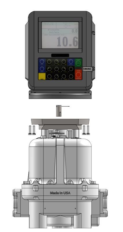
6 Installation Procedure TCS 700 Series Meter Before beginning the installation of the TCS 3000, unpack the entire contents of the packaging in a safe location where you will not misplace any of the parts. Lay out the parts as they would be installed on the truck. This will ensure that you have all the correct parts for the installation. Verifying all the necessary parts were included in the shipment in advance will reduce the truck downtime and avoid any wasted truck preparation work. Installation Procedure: Item Qty TCS P/N Phillips Pan MS M4X8 6 TCS Spring Washer M4 6 TCS Terminal Cover 1 TCS Reg. 7.5 AMP Fuse 1 TCS Reg. Fuse Holder 1 TCS Cable Gland, M12 4 TCS O-Ring, M12 4 TCS USB Fem/Mini Male Cable 1 TCS Resistor 1K OHM 2 TCS /4 28X1 Zinc Bolt 2 TCS /4-28X1 Drilled Bolt 2 TCS68013D 3/64 X 1 Cotter Pin 1 TCS :700 Meter Drive Shaft 1 TCS TCS 3000 to TCS 700 Meter Install Kit (TCS300870) 1. Remove and put aside the four mounting bolts and any mounting adaptor. Remove the existing mechanical register or electronic register, if applicable. Use a box or container to set old equipment and parts in. 2. Remove adjuster dust cover plate from the front of the meter. Remove existing adjuster and drive shaft. Set adjuster dust cover aside in a box or container where it will not be misplaced. Screw the screws back into meter unit. Notice the type of vertical drive shaft in the meter. 3. Using the shaft specific to your installation, slide the Drive Shaft Adaptor on the Pulser and align the holes. Once the holes are aligned insert the Cotter Pin and bend the pin ends back around the Shaft Adaptor. 4. Slide the Adaptor onto the Meter Drive Shaft. 5. Rotate the TCS 3000 until the display is facing in the desired direction and check to see that the meter holes align with the holes at the base of the TCS Secure the bolts. 6


7 7 TCS 3000 Installation

8 Installation Procedure TCS 682 Series Meter Before beginning the installation of the TCS 3000, unpack the entire contents of the packaging in a safe location where you will not misplace any of the parts. Lay out the parts as they would be installed on the truck. This will ensure that you have all the correct parts for the installation. Verifying all the necessary parts were included in the shipment in advance will reduce the truck downtime and avoid any wasted truck preparation work. Item Qty TCS P/N Phillips Pan MS M4X8 6 TCS Spring Washer M4 6 TCS Terminal Cover 1 TCS Reg. 7.5 AMP Fuse 1 TCS Reg. Fuse Holder 1 TCS Cable Gland 4 TCS O-Ring 4 TCS USB Fem/Mini Male Cable 1 TCS Resistor 1K OHM 2 TCS Coupling 682 to LCR II 1 TCS /4 28 X 3/4 Zinc Bolt 2 TCS /4 28 X 3/4 Drilled Bolt 2 TCS68004D Coupling, TCS /4 28 X 1 Zinc Bolt 2 TCS /4 28 X 1 Zinc Drilled Bolt 2 TCS68013D 3/64 X 1 Cotter Pin 1 TCS TCS 3000 to TCS 682 Meter Install Kit (TCS300871) Installation Procedure: 1. Remove and put aside the four mounting bolts and any mounting adaptor. Remove the existing mechanical register or electronic register, if applicable. Use a box or container to set old equipment and parts in. 2. Using the shaft specific to your installation, slide the Drive Shaft Adaptor on the Pulser Shaft and align the holes. Once the holes are aligned insert the Cotter Pin and bend the pin ends back around the Shaft Adaptor. 3. Slide the Adaptor onto the Meter Drive Shaft. 4. Rotate the TCS 3000 until the display is facing in the desired direction and check to see that the meter holes align with the holes at the base of the TCS Secure the bolts. 8

9 9 TCS 3000 Installation


10 Installation Procedure 3000 Remote Mount/Pulser Before beginning the installation of the TCS 3000, unpack the entire contents of the packaging in a safe location where you will not misplace any of the parts. Lay out the parts as they would be installed on the truck. This will ensure that you have all the correct parts for the installation. Verifying all the necessary parts were included in the shipment in advance will reduce the truck downtime and avoid any wasted truck preparation work. Item Qty TCS P/N Metric Phillips Pan MS M4X8 6 TCS Spring Washer M4 6 TCS Terminal Cover 1 TCS Reg. 7.5 AMP Fuse 1 TCS Reg. Fuse Holder 1 TCS Cable Gland 1/2 NPT 4 TCS O-Ring 4 TCS USB Fem/Mini Male Cable 1 TCS Resistor 1K OHM 2 TCS TCS 3000 to Wall Mount Install Kit (TCS300877) TCS P/N NPT Item Qty TCS P/N Pulser 1 TCS Pulser Nut 1/2 32 Hex 1 TCS Terminal Cover 1 TCS O-Ring 013 FKM 1 TCS TCS 3000 Pulser Kit (TCS ) Installation Procedure: 1. Use the wall mount kit to mount the TCS3000 in your desired location. 2. Follow the directions (TCS900030) to install the Pulser on the meter. 3. Once the Pulser is wired, run the corresponding wire cable into the back of the TCS Insert the pulser wiring into the cable gland. Wire the pulser into the correct pulser location on the terminal board. Leave a small amount of slack on the wiring. 5. Compress the cable gland on the TCS3000 until it is snug on the pulser wire. 10


11 11 TCS 3000 Installation


12 Installation Procedure Electronic Air Eliminator Installation Procedure: 1. Locate the air eliminator float wiring in the metering system. 2. Screw the cable gland into the back of the TCS 3000 and tighten into the housing. 3. Run the air eliminator float wiring in the cable gland. Wire the air eliminator float into the correct location on the terminal board. Leave a small amount of slack on the wiring. 4. Compress the cable gland on the TCS3000 until it is snug on the air eliminator float wiring. Air Eliminator Float Wiring 12


13 TCS 3000 Installation Air Eliminator Solenoid 5. Locate the air eliminator solenoid wiring in the metering system. 6. Screw the cable gland into the back of the TCS 3000 and tighten into the housing. 7. Run the air eliminator solenoid wiring in the cable gland. Wire the air eliminator solenoid into the correct location on the terminal board. Leave a small amount of slack on the wiring. 8. Compress the cable gland on the TCS3000 until it is snug on the air eliminator solenoid wiring. 13
 for wiring the solenoid. 3. Mount the 3 Way Valve directly to the TCS3000 and follow the instructions provided with the Valve.")
14 Installation Procedure 3-Way LPG Valve Installation Procedure: 1. Using the bolts and gasket provided, install the valve on the outlet side of the meter. 2. Follow the instructions provided with the valve (TCS ) for wiring the solenoid. 3. Mount the 3 Way Valve directly to the TCS3000 and follow the instructions provided with the Valve. *Note: Use Correct Thread Sealant* 4. Once the solenoid is wired, run the corresponding wire as pictured using a minimum of 22gauge shielded cable into the back of the TCS Insert the solenoid wiring into the cable gland. Wire the solenoid into the correct solenoid location on the terminal board. Leave a small amount of slack on the wiring. 6. Compress the cable gland on the TCS3000 until it is snug on the solenoid wire. *When Calibrating the Unit Set Up Valve Type as 1001* 14

 S2")
15 TCS 3000 Installation Versa Valve S1 (Main) S2 (Bypass) 15
 for wiring the solenoid. 3.")
16 Installation Procedure Single Stage Valve Installation Procedure: 1. Using the bolts and gasket provided, install the valve on the outlet side of the meter. 2. Follow the instructions provided with the valve (TCS ) for wiring the solenoid. 3. Once the solenoid is wired, run the corresponding wire as pictured using a minimum of 22gauge shielded cable into the back of the TCS Insert the solenoid wiring into the cable gland. Wire the solenoid into the correct solenoid location on the terminal board. Leave a small amount of slack on the wiring. 5. Compress the cable gland on the TCS3000 until it is snug on the solenoid wire. 16
 for wiring the solenoid. 3.")
17 TCS 3000 Installation Installation Procedure Single Stage Valve Installation Procedure: 1. Using the bolts and gasket provided, install the valve on the outlet side of the meter. 2. Follow the instructions provided with the valve (TCS ) for wiring the solenoid. 3. Once the solenoid is wired, run the corresponding wire as pictured using a minimum of 22gauge shielded cable into the back of the TCS Insert the solenoid wiring into the cable gland. Wire the solenoid into the correct solenoid location on the terminal board. Leave a small amount of slack on the wiring. 5. Compress the cable gland on the TCS3000 until it is snug on the solenoid wire. 17
18 Installation Procedure Single Stage Valve Installation Procedure: 1. Using the bolts and gasket provided, install the valve on the outlet side of the meter. 2. Follow the instructions provided with the valve (TCS ) for wiring the solenoid. 3. Once the solenoid is wired, run the corresponding wire as pictured using a minimum of 22gauge shielded cable into the back of the TCS Insert the solenoid wiring into the cable gland. Wire the solenoid into the correct solenoid location on the terminal board. Leave a small amount of slack on the wiring. 5. Compress the cable gland on the TCS3000 until it is snug on the solenoid wire. 18
19 TCS 3000 Installation Installation Procedure Stage Valve S1 (Main) S2 (Bypass) Installation Procedure: 1. Using the bolts and gasket provided, install the valve on the outlet side of the meter. 2. Follow the instructions provided with the valve (TCS ) for wiring the solenoid. 3. Once the solenoid is wired, run the corresponding wire as pictured using a minimum of 22gauge shielded cable into the back of the TCS Insert the solenoid wiring into the cable gland. Wire the solenoid into the correct solenoid location on the terminal board. Leave a small amount of slack on the wiring. 5. Compress the cable gland on the TCS3000 until it is snug on the solenoid wire. *When Calibrating the Unit Set Up Valve Type as 1101* 19

20 Installation Procedure Stage Valve S1 (Main) S2 (Bypass) Installation Procedure: 1. Using the bolts and gasket provided, install the valve on the outlet side of the meter. 2. Follow the instructions provided with the valve (TCS ) for wiring the solenoid. 3. Once the solenoid is wired, run the corresponding wire as pictured using a minimum of 22gauge shielded cable into the back of the TCS Insert the solenoid wiring into the cable gland. Wire the solenoid into the correct solenoid location on the terminal board. Leave a small amount of slack on the wiring. 5. Compress the cable gland on the TCS3000 until it is snug on the solenoid wire. *When Calibrating the Unit Set Up Valve Type as 1101* 20


21 TCS 3000 Installation Installation Procedure Vibronic Sensor Installation Procedure: Instructions to follow. 21
22 22 Installation Procedure Timing Relay

23 TCS 3000 Installation Installation Procedure Temperature Probe Installation Procedure: 1. Locate the thermowell in the metering system. 2. Slide the temperature probe jacket over the temperature probe wire until it covers the entire wire. 3. Screw the cable gland into the thermowell and tighten. Squeeze the Copper Anti Sieze on the metal tip of the temperature probe. 4. Slide the temperature probe into the thermowell. Compress the cable gland down onto the temperature probe. 5. Screw the cable gland into the back of the TCS3000 and tighten. 6. Insert the temperature probe wiring into the cable gland. Wire the Temp. Probe into the Temp Probe location on the terminal board. Leave a small amount of slack on the wiring. 7. Compress the cable gland on the TCS3000 until it is snug on the temperature probe wire. 23

24 Installation Procedure Temperature Probe Cont. 8. Run the temperature probe wiring to the back of the TCS Insert the wiring into the third cable gland from the top of the register as pictured on page Leave slack in the temperature probe wiring and tighten the cable gland down on the temperature probe. If Needed the probe wire may be trimmed of excess wire before tightening down the cable gland. 10. Wire the probe into the TCS 3000 as pictured. 24
25 TCS 3000 Installation Item Qty TCS P/N Cable Gland M20X1.5 UL 1 TCS O-Ring Buna M20 Gland 1 TCS Cable Gland, 1/2 MPT UL 1 TCS O-Ring, 1/2NPT Gland 1 TCS Wire Temp Probe SS En 1 TCS Temperature Probe Jacket 1 TCS Capplug T6X 1 TCS Copper Antiseize 2 Gram 1 TCS Thermowell 1/2 Stainless 1 TCS Thermowell 3/8 Stainless 1 TCS TCS 3000 RTD Probe/SS Thermowell Kit (TCS ) Item Qty TCS P/N Cable Gland M20X1.5 UL 1 TCS O-Ring Buna M20 Gland 1 TCS Cable Gland, 1/2 MPT UL 1 TCS O-Ring, 1/2NPT Gland 1 TCS Wire Temp Probe SS En 1 TCS Temperature Probe Jacket 1 TCS Capplug T6X 1 TCS Copper Antiseize 2 Gram 1 TCS TCS 3000 RTD Probe Only Kit (TCS ) Item Qty TCS P/N Cable Gland M20X1.5 UL 1 TCS O-Ring Buna M20 Gland 1 TCS Cable Gland, 1/2 MPT UL 1 TCS O-Ring, 1/2NPT Gland 1 TCS Wire Temp Probe SS En 1 TCS Temperature Probe Jacket 1 TCS Capplug T6X 1 TCS Copper Antiseize 2 Gram 1 TCS Thermowell 1/2 Aluminum 1 TCS Thermowell 3/8 Aluminum 1 TCS


26 Installation Procedure Printer Installation Procedure: 1. Find a suitable location for the printer appropriate to your application. 2. Secure the printer in place with the Velcro strip provided. 3. Wire the power and communication cables into the back of the printer. 4. Run the communication cable to the back of the TCS Screw the cable gland into the back of the TCS3000 and tighten. 6. Insert the printer communication cable into the cable gland and wire into the correct location on the terminal board. 7. Compress the cable gland on the TCS3000 until it is snug on the printer communication cable. The DIP Switch on Pole 3 must be set to ON. NOTE: Once DIP Switch 3 has been moved to position ON; You must cycle power for the Parameter to retain. 26
27 TCS 3000 Installation TCS 3000 Epson Slip 12 VDC Kit (Metric TCS / NPT TCS ) Item Qty Metric TCS P/N NPT TCS P/N Cable Gland M20X1.5 UL 1 TCS O-Ring, Buna M20 Glad 1 TCS O-Ring, 1/2 NPT Gland 1 - TCS VDC Epson Printer Power 1 TCS TCS Wire Printer Comm Cable 1 TCS TCS Velcro 4 X 5 1 TCS TCS Epson Printer 1 TEL TMU TEL TMU Wehof Order Form 1 TCS WEHOF TCS WEHOF TCS 3000 Epson Slip 24 VDC Print Kit (Metric TCS / NPT TCS ) Item Qty Metric TCS P/N NPT TCS P/N Cable Gland M20X1.5 UL 1 TCS O-Ring, Buna M20 Glad 1 TCS O-Ring, 1/2 NPT Gland 1 - TCS Wire Printer Comm Cable 1 TCS TCS Velcro 4 X 5 1 TCS TCS Epson Printer 1 TEL TMU TEL TMU VDC Epson Printer Power 1 TCS TCS Wehof Order Form 1 TCS WEHOF TCS WEHOF TCS 3000 Epson Slip Print 110V Kit (Metric TCS / NPT TCS ) Item Qty Metric TCS P/N NPT TCS P/N Cable Gland M20X1.5 UL 1 TCS O-Ring, Buna M20 Glad 1 TCS Cable Gland, 1/2 NPT UL 1 - TCS O-Ring, 1/2 NPT Gland 1 - TCS Wire Printer Comm. Cable 1 TCS TCS Velcro 4 X 5 1 TCS TCS Epson Printer 1 TEL TMU TEL TMU AC Power Supply w Cord 1 TEL TPS-180 TEL TPS-180 Wehof Order Form 1 TCS WEHOF TCS WEHOF 27
28 TCS 3000 Epson Roll 12 VDC Kit (Metric TCS / NPT TCS ) Item Qty Metric TCS P/N NPT TCS P/N Cable Gland M20X1.5 UL 1 TCS O-Ring, Buna M20 Glad 1 TCS Cable Gland, 1/2 NPT Gland 1 - TCS O-Ring, 1/2 NPT Gland 1 - TCS VDC Epson Printer Power 1 TCS TCS Wire Printer Comm. Cable 1 TCS TCS Velcro 4 X 5 1 TCS TCS Roll Printer 1 TEL TMU220A103 TEL TMU220A103 Wehof Order Form 1 TCS WEHOF TCS WEHOF TCS 3000 Epson Roll 24 VDC Print Kit (Metric TCS / NPT TCS ) Item Qty Metric TCS P/N NPT TCS P/N Cable Gland M20X1.5 UL 1 TCS O-Ring, Buna M20 Glad 1 TCS Cable Gland, 1/2 NPT Gland 1 - TCS O-Ring, 1/2 NPT Gland 1 - TCS Wire Printer Comm Cable 1 TCS TCS Velcro 4 X 5 1 TCS TCS VDC Epson Printer Power 1 TCS TCS Roll Printer 1 TEL TMU220A103 TEL TMU220A103 Wehof Order Form 1 TCS WEHOF TCS WEHOF TCS 3000 Epson Roll 110 VAC Print Kit (Metric TCS / NPT ) Item Qty Metric TCS P/N NPT TCS P/N Cable Gland M20X1.5 UL 1 TCS O-Ring, Buna M20 Glad 1 TCS Cable Gland, 1/2 NPT Gland 1 - TCS O-Ring, 1/2 NPT Gland 1 - TCS Wire Printer Comm Cable 1 TCS TCS Velcro 4 X 5 1 TCS TCS Roll Printer 1 TEL TMU220A103 TEL TMU220A VAC Epson Printer Power 1 TCS TCS Wehof Order Form 1 TCS WEHOF TCS WEHOF 28
29 TCS 3000 Installation * TCS 3000 Printek Bluetooth Kit (Metric TCS / NPT TCS ) Item Qty Metric TCS P/N NPT TCS P/N Cable Gland M20X1.5 UL 1 TCS O-Ring Buna M20 Gland 1 TCS Cable Gland, 1/2 NPT UL 1 - TCS O-Ring, 1/2 NPT Gland 1 - TCS Printek Printer 1 TCS TCS Velcro 4 X 5 1 TCS TCS Bluetooth Modem 1 TCS TCS Printek Charger 1 TCS TCS Printek Blue Tooth Docking 1 TCS TCS Wehof Order Form 1 TCS WEHOF TCS WEHOF * TCS 3000 Printek Bluetooth Kit (Metric TCS / NPT TCS ) Item Qty Metric TCS P/N NPT TCS P/N Cable Gland M20X1.5 UL 1 TCS O-Ring Buna M20 Gland 1 TCS Cable Gland, 1/2 NPT UL 1 - TCS O-Ring, 1/2 NPT Gland 1 - TCS Printek Printer 1 TCS TCS Velcro 4 X 5 1 TCS TCS Bluetooth Modem 1 TCS TCS Printek Charger 1 TCS TCS Printek Blue Tooth Docking 1 TCS TCS Wehof Order Form 1 TCS WEHOF TCS WEHOF * TCS 3000 Citizen Bluetooth Kit (Metric TCS / NPT TCS ) Item Qty Metric TCS P/N NPT TCS P/N Cable Gland M20X1.5 UL 1 TCS O-Ring Buna M20 Gland 1 TCS Cable Gland, 1/2 NPT UL 1 - TCS O-Ring, 1/2 NPT Gland 1 - TCS Velcro 4 X 5 1 TCS TCS Bluetooth Modem 1 TCS TCS Ciztizen Bluetooth Print 1 TCS TCS DC Truck Adapter/Citize 1 TCS TCS Wehof Order Form 1 TCS WEHOF TCS WEHOF *Bluetooth Modem will not pair with other devices, unless TCS Programs the device at the Factory* 29
30 TCS 3000 Citizen Wifi Kit (Metric TCS / NPT TCS ) Item Qty Metric TCS P/N NPT TCS P/N Cable Gland M20X1.5 UL 1 TCS O-Ring Buna M20 Gland 1 TCS Cable Gland, 1/2 NPT Gland 1 - TCS O-Ring, 1/2 NPT Gland 1 - TCS Velcro 4 X 5 1 TCS TCS Bluetooth Modem 1 TCS TCS DC Truck Adapter/Citize 1 TCS TCS Citizen Wifi Printer CM 1 TCS TCS Wehof Order Form 1 TCS WEHOF TCS WEHOF TCS 3000 Epson Slip 12V QD Print Kit (Metric TCS / NPT TCS ) Item Qty Metric TCS P/N NPT TCS P/N Cable Gland M20X1.5 UL 1 TCS O-Ring, Buna M20 Glad 1 TCS Cable Gland, 1/2 NPT Gland 1 - TCS O-Ring, 1/2 NPT Gland 1 - TCS VDC Epson Printer Power 1 TCS TCS Velcro 4 X 5 1 TCS TCS Epson Printer 1 TEL TMU TEL TMU Wehof Order Form 1 TCS WEHOF TCS WEHOF TCS 3000 Epson Slip 24V QD Print Kit (Metric TCS / NPT TCS ) Item Qty Metric TCS P/N NPT TCS P/N Cable Gland M20X1.5 UL 1 TCS O-Ring, Buna M20 Glad 1 TCS Cable Gland, 1/2 NPT Gland 1 - TCS O-Ring, 1/2 NPT Gland 1 - TCS Wire Printer Comm Cable 1 TCS TCS Velcro 4 X 5 1 TCS TCS Epson Printer 1 TEL TMU TEL TMU VDC Epson Printer Power 1 TCS TCS Wehof Order Form 1 TCS WEHOF TCS WEHOF 30

31 TCS 3000 Installation TCS 3000 Epson Slip Print 110V QD Kit (Metric TCS / NPT TCS ) Item Qty Metric TCS P/N NPT TCS P/N Cable Gland M20X1.5 UL 1 TCS O-Ring, Buna M20 Glad 1 TCS Cable Gland, 1/2 NPT Gland 1 - TCS O-Ring, 1/2 NPT Gland 1 - TCS Wire Printer Comm Cable 1 TCS TCS Velcro 4 X 5 1 TCS TCS Epson Printer 1 TEL TMU TEL TMU VAC Epson Printer Power 1 TCS TCS Wehof Order Form 1 TCS WEHOF TCS WEHOF TCS 3000 Epson Roll 12V QD Kit (Metric TCS / NPT TCS ) Item Qty Metric TCS P/N NPT TCS P/N Cable Gland M20X1.5 UL 1 TCS O-Ring, Buna M20 Glad 1 TCS Cable Gland, 1/2 NPT Gland 1 - TCS O-Ring, 1/2 NPT Gland 1 - TCS VDC Epson Printer Power 1 TCS TCS Wire Printer Comm Cable 1 TCS TCS Velcro 4 X 5 1 TCS TCS Roll Printer 1 TEL TMU220A103 TEL TMU220A103 Wehof Order Form 1 TCS WEHOF TCS WEHOF TCS 3000 Epson Roll 24V QD Print Kit (Metric TCS / NPT TCS ) Item Qty Metric TCS P/N NPT TCS P/N Cable Gland M20X1.5 UL 1 TCS O-Ring, Buna M20 Glad 1 TCS Cable Gland, 1/2 NPT Gland 1 - TCS O-Ring, 1/2 NPT Gland 1 - TCS Wire Printer Comm Cable 1 TCS TCS Velcro 4 X 5 1 TCS TCS VDC Epson Printer Power 1 TCS TCS Roll Printer 1 TEL TMU220A103 TEL TMU220A103 Wehof Order Form 1 TCS WEHOF TCS WEHOF 31

 Item Qty Metric TCS P/N NPT TCS P/N Velcro 4 X 5 1 TCS 300721 TCS 300721 Comm. Cable 35 Quick DI 1 TCS 300762 TCS 300762 Bulkhead Conn. For Comm.")
32 TCS 3000 Epson Roll 110V QD Print Kit (Metric TCS / NPT ) Item Qty Metric TCS P/N NPT TCS P/N Velcro 4 X 5 1 TCS TCS Comm. Cable 35 Quick DI 1 TCS TCS Quick Disc Splitter W/2 1 TCS TCS NPT Bulkhead Comm. Fitting 1 TCS TCS AC Power Supply W/Cord 1 TEL TPS-180 TEL TPS-180 Roll Printer 1 TEL TMU220A103 TEL TMU220A103 Wehof Order Form 1 TCS WEHOF TCS WEHOF TCS 3000 Blaster Printer QD Print Kit (Metric TCS / TCS300993) Item Qty Metric TCS P/N NPT TCS P/N Velcro 4 X 5 1 TCS TCS Comm. Cable 35 Quick DI 1 TCS TCS Bulkhead Conn. For Comm. 1 TCS TCS QD Splitter Cable 1 TCS TCS Blaster Printer 1 TCS TCS Wehof Order Form 1 TCS WEHOF TCS WEHOF 32

33 TCS 3000 Installation Installation Procedure Remote Display Installation Procedure: Instructions to follow. 33
34 Installation Procedure Daisy Chain Printer Daisy Chain: Daisy Chain is used for linking multiple registers together to use one printer or to link multiple registers to the database. To Daisy Chain the Registers use a two wire 22 gauge shielded cable. Nominate one Register to be the Host. Once you ve chosen which Register will be the Host the other Registers will be considered the clients. Strip a small amount of wire and run the wire from slot A and B of DAISY CHAIN on the Host Unit to slot A and B of DAISY CHAIN on the Client Unit. To tie the Client to the next Client unit on the Daisy Chain, strip a small amount of wire and run the wire from slot A and B of DAISY CHAIN to slot A and B of the next client s DAISY CHAIN. B A B A B A B A Host Client 2 Client 3 Client 4 The Host will have 2 wires. Client 2 will have 4 wires. Client 3 will have 4 wires. The Last Client will have 2 wires. B B B B A A A A Continue to Daisy Chain until you have tied the chain together, alternating slots on the Daisy Chain until you ve reached the end of the chain. The Host and the last Slave on the chain will be the only two registers on the chain to have a one wire connection. 34
35 Daisy Chain for the Printer TCS 3000 Installation Connect the Printer to the Host Register. To set the Host : Enable the Printer: SYSTEM MENU SYSTEM SETTINGS PRINTER SETTINGS ENABLE/DISABLE PRINTER ENABLE PRINTER Select the Printer: PRINTER SETTINGS SELECT PRINTER [SELECTED PRINTER] ENABLE Selecting the Host Register Select Register as Host: PRINTER SETTINGS DISABLE/ENABLE HOST ENABLE Select the Client Range: PRINTER SETTINGS PRINTER HOST CLIENTS ADDRESS RANGE CLIENTS RANGE START ADDRESS [ Enter 2 and Select] CLIENTS RANGE END ADDRESS [ Enter the number of Registers on the Chain and Select] Selecting the Client Register *Please Note the Host is always # 1. The Client always starts at #2* SYSTEM SETTINGS CONNECTIVITY SETTINGS NETWORK SETTINGS ADDRESS DEVICE ADDRESS [Select the number of the unit you are using ex. 2 if it is the second register on the chain or 3 if it s the third register on the chain.] To Connect to the Chain: SYSTEM SETTINGS CONNECTIVITY SETTINGS NETWORK SETTINGS INTERFACE BRIDGE [Only used when there are 2 Registers tied in the chain] TRANSFER DATA BETWEEN RS232 <-> RS485 INTERFACES ENABLED Continue the Selecting Client Register steps for every Client on the Chain. You may only use the Daisy Chain on five devices at a time. You may not Chain more than five devices together. 35
36 Installation Procedure Daisy Chain Modem Daisy Chain: Daisy Chain is used for linking multiple registers together to use one printer or to link multiple registers to the database. To Daisy Chain the Registers use a two wire 22 gauge shielded cable. Nominate one Register to be the Host. Once you ve chosen which Register will be the Host the other Registers will be considered the clients. Strip a small amount of wire and run the wire from slot A and B of DAISY CHAIN on the Host Unit to slot A and B of DAISY CHAIN on the Client Unit. To tie the Client to the next Client unit on the Daisy Chain, strip a small amount of wire and run the wire from slot A and B of DAISY CHAIN to slot A and B of the next client s DAISY CHAIN. B A B A B A B A Host Client 2 Client 3 Client 4 The Host will have 2 wires. Client 2 will have 4 wires. Client 3 will have 4 wires. The Last Client will have 2 wires. B B B B A A A A Continue to Daisy Chain until you have tied the chain together, alternating slots on the Daisy Chain until you ve reached the end of the chain. The Host and the last Client on the chain will be the only two registers on the chain to have a one wire connection. 36
37 Selecting the Host Register TCS 3000 Installation Select Register as Host: PRINTER SETTINGS DISABLE/ENABLE HOST ENABLE Select the Client Range: PRINTER SETTINGS PRINTER HOST CLIENTS ADDRESS RANGE CLIENTS RANGE START ADDRESS [ Enter 2 and Select] CLIENTS RANGE END ADDRESS [ Enter the number of Registers on the Chain and Select] Selecting the Client Register Enable the Printer:* *Please Note the Host is always # 1. The Client always starts at #2* PRINTER SETTINGS ENABLE/DISABLE PRINTER ENABLE PRINTER Select the Printer:* PRINTER SETTINGS SELECT PRINTER [REMOTE] ENABLE SYSTEM SETTINGS CONNECTIVITY SETTINGS NETWORK SETTINGS ADDRESS DEVICE ADDRESS [Select the number of the unit you are using ex. 2 if it is the second register on the chain or 3 if it s the third register on the chain.] To Connect to the Chain: SYSTEM SETTINGS CONNECTIVITY SETTINGS NETWORK SETTINGS INTERFACE BRIDGE [Only used when there are 2 Registers tied in the chain] TRANSFER DATA BETWEEN RS232 <-> RS485 INTERFACES ENABLED Continue the Selecting Client Register steps for every Client on the Chain. You may only use the Daisy Chain on five devices at a time. You may not Chain more than five devices together. 37
38 Installation Procedure Wiring Diagrams Standard Wiring 38
39 TCS 3000 Installation Quick Disconnect Wiring 39
 Procedure to upload new software is as follows: 1. Load new software upgrade to a USB thumb drive (dongle).")
40 Installation Procedure Software Update FIGURE 1 Mini USB Port Male Mini USB to Female USB USB Thumb Drive with Item Qty TCS P/N USB FEM/Mini Male Cable 1 TCS TCS 3000 USB 1 TCS Installation Procedure: TCS 3000 Software Update Kit (TCS ) Procedure to upload new software is as follows: 1. Load new software upgrade to a USB thumb drive (dongle). NOTE: The new software upgrade should be the ONLY file on the drive. 2. Open the TCS 3000 register. On the front cover of the register, there are 2 mini-usb connections. Using a factory supplied USB cable, attach the thumb drive to the USB port closest to the inside of the register. This port is the highest on the circuit board of the two. See Figure Plug the USB cable into the USB port, and then insert the USB thumb drive into the mating cable (see Figure 1). 4. Under Advanced Functions, locate System Update and press ENTER. 5. The screen will display System Update, press MODE to continue with the update. 6. If the thumb drive is not recognized or there is a faulty cable, the display will respond with NO UPDATE DATA error message. 7. Once the file is recognized, you will be prompted to remove the media. Remove the USB and the register will re boot and begin the update process. This should take approximately 4 minutes. 40
41 TCS 3000 Installation Installation Procedure Warranty Information WARRANTY New 3000 electronic registers, equipment or components manufactured by Total Control Systems, a division of Murray Equipment, Inc. (TCS) with which this warranty is enclosed, are warranted by TCS to the original purchaser only for a period of TWELVE (12) months from installation or eighteen (18) months from the date of shipment, to be free, under normal use and service, from defects in material and workmanship. Defects occurring within the stated warranty period, TCS will repair or replace, at TCS s option; provided that part or parts are returned to TCS transportation charges prepaid, and TCS s examination discloses the parts or workmanship to have been defective upon delivery to the purchaser. EXCLUSIONS Warranty does not cover any parts and equipment not manufactured by TCS, but these items may be covered by separate warranties of their respective manufacturers. This warranty does not extend to any equipment that has been subjected to misuse, negligence or accident or if operated in any manner other than in accordance with TCS s operating instructions and specifications. CLAIM PROCEDURES In order to obtain performance by TCS of its obligations under this warranty, the original purchaser must obtain a Return Goods Authorization (RGA) number from TCS s customer service department within 30 days of discovery of a purported breach of warranty, but not later than the expiration of the warranty period. Once authorization is received, return the defective meter, piece of equipment, or component covered by this warranty, with transportation charges prepaid, to TCS at the address shown below together with a written statement setting forth the nature of the defect and RGA number. LIMITATIONS THERE ARE NO OTHER WARRANTIES OF ANY KIND, EXPRESS OR IMPLIED. TCS SPECIFICALLY DIS- CLAIMS ANY WARRANTY OF MERCHANTABILITY OR OF FITNESS FOR ANY PARTICULAR PURPOSE. TCS will determine if all parts or meter defect falls within the warranty guidelines and will repair or replace within a reasonable time span. TCS is not responsible for any in or out bound freight. TCS's sole obligation that shall represent the buyer's sole and exclusive remedy shall be to repair or at TCS's option to replace any product or part determined to be defective. In no event shall TCS be liable for any special, direct, indirect, incident, consequential or other damages of similar nature, including without limitation, loss of profits, products, production time, or loss of expenses of any nature incurred by the buyer or any third party. TCS has not authorized on its behalf any representation or warranties to be made, nor any liability to be assumed except as expressly provided herein; there is no other express or implied warranty. DESIGN AND EQUIPMENT CHANGES Any changes in design or improvements added shall not create any obligation to install same on equipment previously sold or ordered. 41
42 42
43 43 TCS 3000 Installation
 348-4753 Phone: (260)")
44 TCS REV Charleston Place Fort Wayne, IN Toll Free: (800) Phone: (260) Fax: (260) sales@tcsmeters.com Website:
TCS Installation Manual ELECTRONIC REGISTER. Catalog Title. Catalog Subtitle
 TCS 3000 Catalog Title ELECTRONIC REGISTER Catalog Subtitle Installation Manual Table of Contents Table of Contents 2 Receipt & Inspection 3 Notice 3 Introduction 4 System Specifications 4 Dimensions 5
Installation, Operation & Maintenance Manual
 Cat alog Title Catalog Subtitle TCS 900030, Rev 4 DMP100 / RMP100 Pulse Transmitter Installation, Operation & Maintenance Manual Page 2 NOTES: Page 3 Table of Contents Notes 2 Warning Symbols 3 Notice
Lubricator Gun: 10,000 psi (700 bar) Maximum Delivery Pressure when disconnected from Dispenser
 Maximum Delivery Pressure when disconnected from Dispenser") INSTRUCTIONS-PARTS LIST 30 455 INSTRUCTIONS This manual contains important warnings and information. READ AND KEEP FOR REFERENCE. Rev. C Supercedes B Hand-Operated Portable Grease Dispenser Buckshot Luber
INSTRUCTIONS-PARTS LIST 30 455 INSTRUCTIONS This manual contains important warnings and information. READ AND KEEP FOR REFERENCE. Rev. C Supercedes B Hand-Operated Portable Grease Dispenser Buckshot Luber
LUBRICATOR GUN INSTRUCTIONS-PARTS LIST. 10,000 psi (700 bar) Maximum Delivery Pressure. Detachable-type
 Maximum Delivery Pressure. Detachable-type") INSTRUCTIONS-PARTS LIST 306 460 INSTRUCTIONS This manual contains important warnings and information. READ AND KEEP FOR REFERENCE. Rev. E Supercedes D Detachable-type LUBRICATOR GUN 10,000 psi (700 bar)
INSTRUCTIONS-PARTS LIST 306 460 INSTRUCTIONS This manual contains important warnings and information. READ AND KEEP FOR REFERENCE. Rev. E Supercedes D Detachable-type LUBRICATOR GUN 10,000 psi (700 bar)
Parts Manual V100G Vacuum Machine Part #E (SERIAL #1G G )
") 2006 Perimeter Road. Greenville, SC 29605 Toll Free: 800/435-9340 - Phone: 864/277-5870 Fax: 864/235-9661 - Website address: www.mightymole.com Email address: mmole@mightymole.com Parts Manual V100G Vacuum
2006 Perimeter Road. Greenville, SC 29605 Toll Free: 800/435-9340 - Phone: 864/277-5870 Fax: 864/235-9661 - Website address: www.mightymole.com Email address: mmole@mightymole.com Parts Manual V100G Vacuum
Installation Manual Stand-Alone Dispenser Pan Sensor
 Installation Manual Stand-Alone Dispenser Pan Sensor with Dispenser Control Interface Manual Number 576013-845, Revision C Non-Discriminating Stand-Alone Dispenser Pan Sensor with Dispenser Control Interface
Pressure Roller with 24-inch Fixed Extension - For application of architectural paints and coatings -
 Instructions Important Safety Instructions Read all warnings and instructions in this manual. Save these instructions. 311082D Pressure Roller with 24-inch Fixed Extension - For application of architectural
NEO-DYN MODELS 100T AND 100TC ADJUSTABLE TEMPERATURE SWITCHES; ENCLOSURE 3X FOR WEATHERPROOF APPLICATIONS INSTALLATION AND OPERATION MANUAL
 NEO-DYN MODELS 100T AND 100TC ADJUSTABLE TEMPERATURE SWITCHES; ENCLOSURE 3X FOR WEATHERPROOF APPLICATIONS INSTALLATION AND OPERATION MANUAL PN 610-0012 Rev B Manual No. 610-0012 REV B Neo-Dyn 28150 Industry
TOBi PI Wi-Z. Performance Indicator and Event Logger. Quick Installation Guide
 TOBi PI WiZ Performance Indicator and Event Logger Quick Installation Guide S470180 Revised 6/19/2015 Safety Instructions WARNING BATTERIES CONTAIN LETHAL VOLTAGE LEVELS. INSTALLATION AND SERVICING MUST
CTFRP Series Power Supplies
 CTFRP Series Power Supplies Ferroresonant Non-Standby Power Supplies User Manual Myers Power Products 6/2013 CTFRP Series Manual Chapter 1 General Information The Myers CTFRP Series Power Supply provides
Parts Manual V100G Vacuum Machine Part #E (SERIAL #1G G )
") 2006 Perimeter Road. Greenville, SC 29605 Toll Free: 800/435-9340 - Phone: 864/277-5870 Fax: 864/235-9661 - Website address: www.mightymole.com Email address: mmole@mightymole.com Parts Manual V100G Vacuum
2006 Perimeter Road. Greenville, SC 29605 Toll Free: 800/435-9340 - Phone: 864/277-5870 Fax: 864/235-9661 - Website address: www.mightymole.com Email address: mmole@mightymole.com Parts Manual V100G Vacuum
QSI (Q-Star) Electronics Owner s Manual
 Electronics Owner s Manual") QSI (Q-Star) Electronics Owner s Manual QSI Module (Installs in Plain Cover Plate) QSI2 Shown QSI Module (Installs in Display Mount Cover Plate) QSI2 Shown TABLE OF CONTENTS INTRODUCTION... 2 IMPORTANT
QSI (Q-Star) Electronics Owner s Manual QSI Module (Installs in Plain Cover Plate) QSI2 Shown QSI Module (Installs in Display Mount Cover Plate) QSI2 Shown TABLE OF CONTENTS INTRODUCTION... 2 IMPORTANT
BlinkerBeam Solar Controller
 Blinker Division Solar LED Solutions The Route To Safety, One Solution At A Time BlinkerBeam Solar Controller BlinkerSign, BlinkerBeacon or RRFB 2.0 with 55 W Solar Panel User Guide TAPCO Traffic & Parking
Model , Series A 9 in. (23 cm) roller frame with 45 angle and 12 in. reach 1/2 in. (13 mm) nap roller cover
 roller frame with 45 angle and 12 in. reach 1/2 in. (13 mm) nap roller cover") Operating Instructions 309899 Rev. A This manual contains important warnings and information. READ AND KEEP FOR REFERENCE. INSTRUCTIONS Manufactured by Model 246818, Series A 9 in. (23 cm) roller frame
Operating Instructions 309899 Rev. A This manual contains important warnings and information. READ AND KEEP FOR REFERENCE. INSTRUCTIONS Manufactured by Model 246818, Series A 9 in. (23 cm) roller frame
INSTRUCTIONS PARTS LIST This manual contains important warnings and information. READ AND RETAIN FOR REFERENCE
 INSTRUCTIONS PARTS LIST 308 493 This manual contains important warnings and information. READ AND RETAIN FOR REFERENCE Rev. A Second Gun Hose Kit 100 psi (6.9 bar) Maximum Working Pressure These kits include
LU27 Series Quick Start
 Ultrasonic Liquid Level Transmitter LU27 Series Quick Start 2016 Flowline, Inc. All Rights Reserved Made in USA Flowline, Inc. 10500 Humbolt Street, Los Alamitos, CA 90720 p 562.598.3015 f 562.431.8507
Dispenser Pan Sensors & Containment Sump Sensors
 Manual No: 576013-306 Revision: E Dispenser Pan Sensors & Containment Sump Sensors Installation Guide Notice Veeder-Root makes no warranty of any kind with regard to this publication, including, but not
Cardinal DETECTO. PORTABLE PLATFORM SCALES Digital Type Series 850F Owner s Manual
 Cardinal DETECTO PORTABLE PLATFORM SCALES Digital Type Series 850F Owner s Manual CARDINAL SCALE MFG. CO. PO BOX 151, WEBB CITY, MO 64870 0066-M176-O1 Rev H 10/06 417-673-4631 www.cardinalscale.com Printed
G8 Portable Fuel Transfer Pump Owner s Manual
 G8 Portable Fuel Transfer Pump Owner s Manual GENERAL INFORMATION This pump is designed for use only with gasoline (up to 15% alcohol blends such as E15), diesel fuel (up to 20% biodiesel blends such as
PORTABLE PLATFORM SCALES Digital Type Series 850F Owner s Manual
 PORTABLE PLATFORM SCALES Digital Type Series 850F Owner s Manual Model 850F CARDINAL SCALE MFG. CO. 0066-M176-O1 Rev J 203 E. Daugherty, Webb City, MO 64870 USA 11/14 Ph: 417-673-4631 Fax: 417-673-5001
37SCENE 46SCENE 79SCENE
 Installation and Operation Instructions LED SCENE LIGHT LED SCENE LIGHT 37SCENE 46SCENE 79SCENE 37SCENE 46SCENE Introduction The 37SCENE, 46SCENE, 79SCENE LED Scene Lights are designed for the emergency
Rotary Flow Meter SERVICE MANUAL*
 700-40 Rotary Flow Meter SERVICE MANUAL* * For 700 meters with serial numbers 700000 or higher TOTAL CONTROL SYSTEMS 2515 Charleston Place Fort Wayne, IN 46808 Toll Free: (800) 348-4753 Tel: (260) 484-0382
Model C230 Pump Controller
 MANUAL Model C230 Earthsafe Systems, Inc. 7553 S. Madison Willowbrook, IL 60527 T: (630) 794-5100 F: (630) 794-5106 info@earthsafe.com www.earthsafe.com March 1, 2010 The information contained herein is
PRO ES Test Fixture, High Voltage Test Probe, & KV Meter
 INSTRUCTIONS PARTS LIST 308 217 This manual contains important warnings and information. READ AND RETAIN FOR REFERENCE Rev. B Supersedes A PRO ES Test Fixture, High Voltage Test Probe, & KV Meter To Test
Instructions 3A4793B EN. See page 3 for a complete list of model descriptions and part numbers.
 Instructions Variable Frequency Drives 3A4793B EN Variable frequency drives (VFDs) to power and control electric motor driven agitators. For professional use only. Not approved for use in explosive atmospheres
UniTorq UTQ Quarter-Turn Actuator Installation and Operation Manual
 UniTorq UTQ 1.5 6.4 Quarter-Turn Actuator Installation and Operation Manual Thank you for purchasing our UTQ 1.5-6.0 Electric Actuators Before installation or operation of the actuator carefully review
NEO-DYN MODEL 100P ENCLOSURE 7 ADJUSTABLE EXPLOSION-PROOF PRESSURE SWITCH
 NEO-DYN MODEL 100P ENCLOSURE 7 ADJUSTABLE EXPLOSION-PROOF PRESSURE SWITCH INSTALLATION AND OPERATION MANUAL PN 610-0006 Rev E WARNING CAUTION SPECIAL CONDITIONS FOR SAFE USE NOTE Manual No. 610-0006 Rev
INSTALLATION, CALIBRATION & TROUBLESHOOTING MANUAL
 INSTALLATION, CALIBRATION & TROUBLESHOOTING MANUAL Model 7200 Transducers GP:50 2770 Long Road, Grand Island, NY 14072 Tel: 716-773-9300 Fax: 716-773-5019 Email: sales@gp50.com Website: http://www.gp50.com
Product Owner s Manual. 8 GPM / 30 LPM, 12-volt Fuel Transfer Pump. Model G8P
 Product Owner s Manual EN 8 GPM / 30 LPM, 12-volt Fuel Transfer Pump Model G8P 05/2017 922130-01 Rev. A THANK YOU STATEMENT GOES HERE: Please save these instructions for future reference. Read carefully
Parts Manual Vermeer/ McLaughlin V750 Vacuum Machine (Serial #7G G )
") 2006 Perimeter Road. Greenville, SC 29605 Toll Free: 800/435-9340 - Phone: 864/277-5870 Fax: 864/235-9661 - Website address: www.mightymole.com Email address: mmole@mightymole.com Parts Manual Vermeer/
2006 Perimeter Road. Greenville, SC 29605 Toll Free: 800/435-9340 - Phone: 864/277-5870 Fax: 864/235-9661 - Website address: www.mightymole.com Email address: mmole@mightymole.com Parts Manual Vermeer/
Dispenser Pan Sensors & Containment Sump Sensors
 Manual No: 576013-306 Revision: G Dispenser Pan Sensors & Containment Sump Sensors Installation Guide Notice Veeder-Root makes no warranty of any kind with regard to this publication, including, but not
EchoPod. DL10, DL14, DL24, DS14 & DX10 Series Quick Start. DL14-00 Shown Flowline, Inc. All Rights Reserved Made in USA
 EchoPod Ultrasonic Level Switch, Controller & Transmitter DL10, DL14, DL24, DS14 & DX10 Series Quick Start DL14-00 Shown 2016 Flowline, Inc. All Rights Reserved Made in USA Flowline, Inc. 10500 Humbolt
Extreme Duty Grapple (Rock, Skeleton, Scrap & Tine) Operation and Maintenance Manual
 Operation and Maintenance Manual") Extreme Duty Grapple (Rock, Skeleton, Scrap & Tine) Operation and Maintenance Manual Revision Date: May 12, 2017 Skid Pro PO Box 982 Alexandria, MN 56308 Toll Free: 877-378-4642 www.skidpro.com TABLE OF
Extreme Duty Grapple (Rock, Skeleton, Scrap & Tine) Operation and Maintenance Manual Revision Date: May 12, 2017 Skid Pro PO Box 982 Alexandria, MN 56308 Toll Free: 877-378-4642 www.skidpro.com TABLE OF
BMRX Series ROTARY LEVEL CONTROL
 BMRX Series ROTARY LEVEL CONTROL OPERATING INSTRUCTIONS PLEASE READ CAREFULLY 925-0292 Rev C TABLE OF CONTENTS GENERAL SPECIFICATIONS... 3 SAFETY SUMMARY... 4 1.0 INTRODUCTION... 5 2.0 INSTALLATION...
MFG. CO. INC. DODGE CITY, KANSAS (620) Electric Truck Auger. Owners Manual
 Electric Truck Auger. Owners Manual") MFG. CO. INC. DODGE CITY, KANSAS 67801 (620) 225-0263 4 Electric Truck Auger Owners Manual Sept. 2005 The Farm And Industrial Equipment Institute Safety Alert Symbol BE ALERT! Your Safety is Involved Be
MFG. CO. INC. DODGE CITY, KANSAS 67801 (620) 225-0263 4 Electric Truck Auger Owners Manual Sept. 2005 The Farm And Industrial Equipment Institute Safety Alert Symbol BE ALERT! Your Safety is Involved Be
INW Panel Meter Reading an INW PT12 Sensor
 INW Panel Meter Reading an INW PT12 Sensor PROUDLY MADE IN THE USA ISO 9001:2008 Certified Company Table of Contents Introduction...5 What is an INW Panel Meter for an INW PT12 Smart Sensor?...5 Initial
Thank You. for purchasing an Edelbrock Nitrous Oxide Injection System. Please take the time to read and understand the following.
 Thank You. for purchasing an Edelbrock Nitrous Oxide Injection System. Nitrous Oxide injection is one of the most exciting performance enhancements for the dollar invested on the market today. With the
Model NTX7 Series Automatic Battery Charger User s Manual Rev. 1.0 October 17, 2006
 B R A N D Model NTX7 Series Automatic Battery Charger User s Manual Rev. 1.0 October 17, 2006 For Sales, Support and Service phone: 407-331-4793 fax: 407-331-4708 website: www.xenotronix.com email: information@xenotronix.com
Active Controlled Cooling System
 Active Controlled Cooling System April 2011 3267 Progress Dr Orlando, FL 32826 www.apecor.com Preliminary www.apecor.com Table of Contents General Information... 3 Safety... 3 Introduction... 3 What s
NEUTRALIZATION SYSTEM FOR OPA & GLUTARALDEHYDE MEDI-NEWT. User Manual. Endoscope reprocessing the the way way it it should be be
 NEUTRALIZATION SYSTEM FOR OPA & GLUTARALDEHYDE MEDI-NEWT User Manual Endoscope reprocessing the the way way it it should be be 1 Medi-Newt Neutralization System Instruction Manual 50096-951 Rev C 2011,
Model For petroleum products and other fluids compatible with aluminum and buna-n seals.
 Instructions - Parts List Piston Hand Pump 311308C Model 260407 For petroleum products and other fluids compatible with aluminum and buna-n seals. Model 260406 For herbicides and other chemicals or fluids
Flo-Way. Measure Granular or Powdered Material. Stand Alone or Connect to Other Devices for Blending. Used by Successful Producers World-Wide
 Flo-Way R Solids Impact Flow Meter Measure Granular or Powdered Material Stand Alone or Connect to Other Devices for Blending Used by Successful Producers World-Wide Visit our website: www.beltwayscales.com
MODELS 100T AND 100TC ADJUSTABLE TEMPERATURE SWITCHES,
 NEO-DYN MODELS 100T AND 100TC ADJUSTABLE TEMPERATURE SWITCHES, ENCLOSURE 6N FOR EXPLOSIVE ATMOSPHERES INSTALLATION AND OPERATION MANUAL PN 610-0014 E Manual No. 610-0014 Rev E Neo-Dyn 28150 Industry Drive
II DISTRIBUTION & SUBSTATION TYPE C
 CapCheckIII DISTRIBUTION & SUBSTATION TYPE Ca p a c i t o r C h e c ke r Operating & Instruction Manual 1475 Lakeside Drive Waukegan, Illinois 60085 U.S.A. 847.473.4980 f a x 8 4 7. 4 7 3. 4 9 8 1 w e
BC-9000 OPERATIONS MANUAL BATTERY CHARGER COFKO ELECTRONICS LLC COPYRIGHT 2014 P/N
 BC-9000 BATTERY CHARGER OPERATIONS MANUAL COFKO ELECTRONICS LLC COPYRIGHT 2014 P/N 4169-20 UNPACKING As you unpack your new BC-9000 battery charger, inspect the BC-9000 for signs of shipping damage. If
Parts Manual Vermeer/ McLaughlin Mud System 230P
 2006 Perimeter Road. Greenville, SC 29605 Toll Free: 800/435-9340 - Phone: 864/277-5870 Fax: 864/235-9661 - Website address: www.mightymole.com Email address: mmole@mightymole.com Parts Manual Vermeer/
Switch-Pak. AU13, AV13 & AZ13 Series Owner s Manual. w/ Compact Relay Controller
 Switch-Pak w/ Compact Relay Controller AU13, AV13 & AZ13 Series Owner s Manual Flowline, Inc.. 10500 Humbolt Street, Los Alamitos, CA 90720. p 562.598.3015. f 562.431.8507. w flowline.com MN301430 Rev
Pro Shot Grease Dispense Valve
 Instructions Parts List Pro Shot Grease Dispense Valve 309032J For high pressure grease dispense. 8000 psi (55 MPa, 552 bar) Maximum Working Pressure Model No. 242055, Series B, 1/4 npt Fluid Inlet Model
LU23, LU28 & LU29 Series Quick Start
 Ultrasonic Liquid Level Transmitter LU23, LU28 & LU29 Series Quick Start 2016 Flowline, Inc. All Rights Reserved Made in USA Flowline, Inc. 10500 Humbolt Street, Los Alamitos, CA 90720 p 562.598.3015 f
ASM Maxi Poles. Instruction-Parts B Series. For the application of architectural paints and coatings.
 Instruction-Parts ASM Maxi Poles 312483B For the application of architectural paints and coatings. 3400 Series 4050 psi (27.92 MPa, 280 bar) Maximum Working Pressure Important Safety Instructions Read
Installation Manual Model 3800/3810
 Installation Manual Model 3800/3810 Thermistors & Thermistor Strings No part of this instruction manual may be reproduced, by any means, without the written consent of Geokon, Inc. The information contained
7.3L POWERSTROKE BANJO BOLT KIT Fits L Powerstroke Diesel. Installation Guide
 7.3L POWERSTROKE BANJO BOLT KIT Fits 94-03 7.3L Powerstroke Diesel Installation Guide INSPECT CONTENTS OF THIS KIT THOROUGHLY BEFORE STARTING THE INSTALLATION PROCESS! IF YOU FIND A PROBLEM WITH YOUR PACKAGE:
PUSH BUTTON KEY CABINET
 PUSH BUTTON KEY CABINET Model 95689 INSTALLATION And Operation Instructions Due to continuing improvements, actual product may differ slightly from the product described herein. 3491 Mission Oaks Blvd.,
Battery Back-up BBM Owner's Manual. Please read this manual BEFORE installing your inverter
 Battery Back-up BBM-1225 Owner's Manual Please read this manual BEFORE installing your inverter owner's MAnUAL index section 1 Safety Instructions... 3 section 2 Layout and Dimensions... 4 section 3 Description
Operating and Installation Instructions
 Model Number 20902 Fabricator's Power Module Kit - Aluminum Operating and Installation Instructions CAUTION! This product is to be installed only by persons knowledgeable in the repair and modification
CDS-JOHN BLUE COMPANY
 VRH-1000 HYDRAULIC VARIABLE RATE DRIVE AND MOUNT KIT PARTS AND INSTRUCTION MANUAL CDS-JOHN BLUE COMPANY DIVISION OF ADVANCED SYSTEMS TECHNOLOGY, INC. 290 Pinehurst Drive - Huntsville, Alabama 35806 P.O.
U00X ULTRASONIC LEVEL SWITCH. Ultrasonic Liquid Level Switches INSTALLATION AND OPERATIONS MANUAL. For Models: U002, U003 & U004
 U00X ULTRASONIC LEVEL SWITCH INSTALLATION AND OPERATIONS MANUAL Ultrasonic Liquid Level Switches For Non-Hazardous Locations For Models: U002, U003 & U004 READ THIS MANUAL PRIOR TO INSTALLATION This manual
INSTRUCTIONS PARTS LIST
 INSTRUCTIONS PARTS LIST 30812 This manual contains important warnings and information. READ AND RETAIN FOR REFERENCE See manual 308393 for complete gun washer warnings and instructions. Rev. B AIR SPRAY
Manual No: Revision: F. Mag Probe Assembly Manual
 Manual No: 576013-730 Revision: F Mag Probe Assembly Manual Notice Veeder-Root makes no warranty of any kind with regard to this publication, including, but not limited to, the implied warranties of merchantability
DUSTTRAK AEROSOL MONITOR SOLAR POWER KIT MODEL
 DUSTTRAK AEROSOL MONITOR SOLAR POWER KIT MODEL 854060 (USED FOR POWERING ENVIRONMENTAL ENCLOSURE MODELS MODELS 854030, 8535 AND 8537) OPERATION AND MAINTENANCE MANUAL P/N 6008416, REVISION C JUNE 2017
SUNTURA SOLAR TRACKER
 WindyNation SUNTURA SOLAR TRACKER SOT-TRKS-NF User s Manual Page 1 of 10 WindyNation 08/09/2012 Table of Contents 1 Introduction... 3 1.1 Limited Warranty... 3 1.2 Restrictions... 3 1.3 Warranty Claims
CBC-160-1N and CBC-160-2N Clutch/Brake Controls
 P-239-36 819-04 CBC-160-1N and Clutch/Brake Controls Installation Instructions An Altra Industrial Motion Company Contents Introduction...2 Specifications........................... 2 Installation...3
! "! User Manual Myers Power Products CTEP/G Manual 6/2009
 !"! User Manual Myers Power Products CTEP/G Manual 6/2009 Chapter 1 General Information The Myers Pwer Products (Myers) CTEP/G Series Power Supply Enclosures provide protection for power supplies/ups
Battery Back-up Model: BBM-1225
 Battery Back-up Model: BBM-1225 Owner's Manual Please read this manual before operating your INDEX Safety instructions... 2 Description... 2 Principle of operation...3,4,5,6 Installation... 7,8 Specifications...
RS Gun Front Adapter Kits
 Kit Instructions RS Gun Front Adapter Kits 332520A EN For adapting the internal mix gun for specific field applications. For professional use only. Important Safety Instructions Read all warnings and instructions
Parts Manual Vermeer/ McLaughlin Mud System 230P
 2006 Perimeter Road. Greenville, SC 29605 Toll Free: 800/435-9340 - Phone: 864/277-5870 Fax: 864/235-9661 - Website address: www.mightymole.com Email address: mmole@mightymole.com Parts Manual Vermeer/
SUNC1200 / ITEM #40882 SUBMERSIBLE UTILITY PUMP OPERATIONS MANUAL
 SUNC1200 / ITEM #40882 SUBMERSIBLE UTILITY PUMP OPERATIONS MANUAL WWW.SUNRUNNERPOOL.COM Performance Model HP GPH of Water @ Total Feet Of Lift 0 ft. 5 ft. 10 ft. 15 ft. 20 ft. 25 ft. Max. Lift SUNC1200
VP-4124/VP-4124-E 24/48 VOLT DC SWITCHING POWER SUPPLY
 Issue 5 24/48 VOLT DC SWITCHING POWER SUPPLY INTRODUCTION These instructions provide the specifications, installation and maintenance information for the VP-4124 and VP-4124-E, 24/48 Volt Power Supplies.
Mechanical Physician Scale Installation & Operation Instructions PN
 Mechanical Physician Scale Installation & Operation Instructions PN 102613 The Medical Physician scale is ideal for use in health clinics and doctors practices for height and weight measurement. The scale
AEROMOTIVE Part # FORD POWERSTROKE Fuel System Kit INSTALLATION INSTRUCTIONS
 AEROMOTIVE Part # 11807 08-10 FORD POWERSTROKE Fuel System Kit INSTALLATION INSTRUCTIONS CAUTION: Installation of this product requires detailed knowledge of automotive systems and repair procedures. We
Owner s Manual & Safety Instructions
 Owner s Manual & Safety Instructions Save Save This This Manual Keep Keep this this manual manual for for the the safety safety warnings warnings and and precautions, assembly, assembly, operating, inspection,
SUNC3000 / Item #40885
 SUNC3000 / Item #40885 AUTOMATIC POOL COVER PUMP OPERATIONS MANUAL WWW.SUNRUNNERPOOL.COM 1 . Performance GPH of Water @ Total Feet Of Lift MODEL HP Max. Lift 0 ft. 5 ft. 10 ft. 15 ft. 20 ft. SUNC3000 1/3
INSTALLATION AND MAINTENANCE MANUAL FORM #PM-126 REV A 12/09
 HAND CRANK & MOTORIZED POWER CORD REELS: SERIES 1125PC SERIES: 1125PC HAND CRANK SERIES: 1125PC MOTORIZED COXREELS The technical data and images which appear in this manual are for informational purposes
½ DODGE CUMMINS OEM BYPASS LIFT PUMP KIT Installation Instructions Part #
 29 July 2005 2003-04.5 Dodge Cummins OEM Bypass Lift Pump Kit # 1050227-1 - 2003-04½ DODGE CUMMINS OEM BYPASS LIFT PUMP KIT Installation Instructions Part # 1050227 PLEASE READ ALL INSTRUCTIONS CAREFULLY
Model HPX60 Series Automatic Battery Charger User s Manual Rev. 1.0 October 17, 2006
 B R A N D Model HPX60 Series Automatic Battery Charger User s Manual Rev. 1.0 October 17, 2006 For Sales, Support and Service phone: 407-331-4793 fax: 407-331-4708 website: www.xenotronix.com email: information@xenotronix.com
USB Charge Port Installation Instructions
 USB Charge Port Installation Instructions Lifetime Technical Support support@logolites.com 770-476-7322 www.logolites.com Manual 100-0014C Thank you for purchasing a Logo Lites USB Charge Port! USB Charge
INSTALLATION, INSTRUCTION AND SERVICE MANUAL
 INSTALLATION, INSTRUCTION AND SERVICE MANUAL Actuator/Brake/Trailer Dealer Please provide to consumer. Consumer Read and follow instructions. Keep with trailer for reference. Page 1 of 7 1. Introduction...
EchoPod. UG06 & UG12 Series Quick Start Flowline, Inc. All Rights Reserved Made in USA. Ultrasonic Liquid Level Transmitter
 EchoPod Ultrasonic Liquid Level Transmitter UG06 & UG12 Series Quick Start 2017 Flowline, Inc. All Rights Reserved Made in USA Flowline, Inc. 10500 Humbolt Street, Los Alamitos, CA 90720 p 562.598.3015
Color Change Valve. Instructions Parts List K
 Instructions List Color Change Valve 0K For color changing or distribution of industrial paints and coatings or fluids. 00 psi (0. MPa, bar) Maximum Air Inlet Pressure 00 psi (. MPa, bar) Maximum Fluid
Pressurized oil drain for collection of used lubricants and anti-freeze.
 Instructions - Parts List 24-Gallon (90-Liter) Oil Ace 30864B Pressurized oil drain for collection of used lubricants and anti-freeze. Model 9577 Series A 8 psi (55 kpa,5 bar) Maximum Working Pressure
JOHN DEERE 9970 COTTON PICKERS
 PARTS CATALOG FOR Mud Hog System II Rear Wheel Drive FOR JOHN DEERE 9970 COTTON PICKERS Mud Hog Model Numbers Tread Center OEM Aftermarket JD40005 JD47655 82, 90, 94, 106 TUTHILL Drive Systems 9098 West
SUNTURA HD SOLAR TRACKER
 WindyNation SUNTURA HD SOLAR TRACKER SOT-TRKS-NFHD User s Manual Page 1 of 11 WindyNation 08/09/2012 Table of Contents 1! Introduction... 3! 1.1! Limited Warranty... 3! 1.2! Restrictions... 3! 1.3! Warranty
HATCHGRIP Installation Instructions/Operation and Maintenance Manual
 HATCHGRIP Installation Instructions/Operation and Maintenance Manual Models: HTG-PCG Contact Information Table of Contents: Safety Precautions... 2 Product Information... 2 Operation... 3 Installation
Installation Guide Document N Cleanroom Mirrors Copyright 2016 Terra Universal Inc. All rights reserved. Revised November 2016
 Document N0. 1800-09 Copyright 2016 Terra Universal Inc. All rights reserved. Revised November 2016 Terra Universal, Inc. TerraUniversal.com 800 S. Raymond Ave. Fullerton, CA 92831 TEL: (714) 578-6000
CDS-JOHN BLUE COMPANY
 HYDRAULIC DRIVE KIT FOR VARIABLE RATE OR MANUAL CONTROL SYSTEMS PARTS AND INSTALLATION MANUAL CDS-JOHN BLUE COMPANY DIVISION OF ADVANCED SYSTEMS TECHNOLOGY, INC. 290 Pinehurst Drive - Huntsville, Alabama
User s Guide. EZ-Bar Livestock Scale WEIGH BARS AND DIGITAL INDICATOR. WB-40 Weigh Bars TS-700 WB Digital Indicator. Guide version 1.
 accurate around the world s i n c e 1 8 9 7 User s Guide EZ-Bar Livestock Scale WEIGH BARS AND DIGITAL INDICATOR WB-40 Weigh Bars TS-700 WB Digital Indicator Guide version 1.3 USER S GUIDE Table of Contents
CRD600 Automatic Fitting Inserter
 CRD600 Automatic Fitting Inserter OPERATIONS MANUAL VERSION 2.3 LAST EDITED 12.07.2018 cleanroomdevices.com 1 Table of Contents Title Page.. 1 Table of Contents. 2 1.0 General Product & Safety Information...3
CRD610 Automatic Fitting Inserter
 CRD610 Automatic Fitting Inserter OPERATIONS MANUAL VERSION 1.2 LAST EDITED 12.12.2018 cleanroomdevices.com 1 Table of Contents Title Page. 1 Table of Contents...2 1.0 General Product & Safety Information....3
p.t.o. Slip clutch Read this material before using this product. Failure to do so can result in serious injury. Save this manual.
 p.t.o. Slip clutch 65517 Installation Instructions Distributed exclusively by Harbor Freight Tools. 3491 Mission Oaks Blvd., Camarillo, CA 93011 Visit our website at: http://www.harborfreight.com Read
IAQ-CALC INDOOR AIR QUALITY METER MODEL 7515
 IAQ-CALC INDOOR AIR QUALITY METER MODEL 7515 OPERATION AND SERVICE MANUAL P/N 1980571, REVISION D FEBRUARY 2016 Copyright TSI Incorporated / May 2007-2016 / All rights reserved. Address TSI Incorporated
PARTS AND INSTALLATION MANUAL
 HYDRAULIC DRIVE MOUNTING KIT FOR VARIABLE RATE OR MANUAL CONTROL SYSTEMS PARTS AND INSTALLATION MANUAL BarMount Bracket VRHJD10/15 Kit Shown DirectDrive Bracket 1161391 Kit Shown CDSJOHN BLUE COMPANY DIVISION
DeZURIK 2-24 (50-600mm) KGN-RSB BI-DIRECTIONAL CAST STAINLESS STEEL KNIFE GATE VALVES
 KGN-RSB BI-DIRECTIONAL CAST STAINLESS STEEL KNIFE GATE VALVES") 2-24 (50-600mm) KGN-RSB BI-DIRECTIONAL CAST STAINLESS STEEL KNIFE GATE VALVES Instruction D11023 October 2016 Instructions These instructions provide information about KGN-RSB Knife Gate Valves. They are
2-24 (50-600mm) KGN-RSB BI-DIRECTIONAL CAST STAINLESS STEEL KNIFE GATE VALVES Instruction D11023 October 2016 Instructions These instructions provide information about KGN-RSB Knife Gate Valves. They are
Pneumatic Cylinder 14 Bore X 21 Stroke Part No. P Replaces Part No. P
 Pneumatic Cylinder 14 Bore X 21 Stroke Part No. P -322908-00000 Replaces Part No. P-191067-00000 Service Information WARNING: INSTALLATION AND MOUNTING The user of these devices must conform to all applicable
Battery Charger Retrofit Kit Q-DCCHG1 for DC Cabinet Retrofit Manual
 Battery Charger Retrofit Kit Q-DCCHG1 for DC Cabinet Retrofit Manual 25500181 Rev. A0 415 Printed in U.S.A. Copyright 2015 Federal Signal Corporation Limited Warranty The Alerting and Notification Systems
TRUSS KITS FOR SPOUTING Installation Manual
 TRUSS KITS FOR SPOUTING Installation Manual LAMBTON CONVEYOR LIMITED 102 Arnold Street Wallaceburg, ON N8A 3P4 Canada Telephone: (519) 695-2316 Telephone: (519) 627-8228 ONE SOURCE ONE SOLUTION Toll free:
PART NUMBER: F-706RLSS REVOLUTION LIFT: SLING-SEAT OPTION
 PART NUMBER: F-706RLSS REVOLUTION LIFT: SLING-SEAT OPTION 500 LB. [227 kg] MAXIMUM CAPACITY MANDATORY LEAVE THIS MANUAL WITH LIFT OWNER - WARNING- IMPORTANT SAFETY INSTRUCTIONS 1. READ AND FOLLOW ALL INSTRUCTIONS.
QSB (Q-Star) Electronics for QSE Electromagnetic Meter. Owner s Manual TABLE OF CONTENTS
 Electronics for QSE Electromagnetic Meter. Owner s Manual TABLE OF CONTENTS") Owner s Manual QSB (Q-Star) Electronics for QSE Electromagnetic Meter Plain Cover Plate and Pulse-Out Transmitter (QSB) Display Mount Cover Plate (to mount a Q09 Display) and Pulse-Out Transmitter (QSB)
Owner s Manual QSB (Q-Star) Electronics for QSE Electromagnetic Meter Plain Cover Plate and Pulse-Out Transmitter (QSB) Display Mount Cover Plate (to mount a Q09 Display) and Pulse-Out Transmitter (QSB)
EV-2051-M Electric Motor. Operation and Maintenance Manual
 EV-2051-M Electric Motor Operation and Maintenance Manual Table of Contents Safety... 3 General...3 Safety Notices...6 Cautions, Warnings and Dangers...7 Cautions...8 Warnings...11 Dangers...13 Important
CDS-JOHN BLUE COMPANY
 HYDRAULIC DRIVE KIT FOR VARIABLE RATE OR MANUAL CONTROL SYSTEMS PARTS AND INSTALLATION MANUAL BarMount Bracket DirectDrive Bracket CDSJOHN BLUE COMPANY DIVISION OF ADVANCED SYSTEMS TECHNOLOGY, INC. 290
Buhler Versatile 23XX/24XX, Versatile 9X80, and New Holland Versatile 9X8X SmarTrax MD Installation Manual. P/N Rev A 04/16 E23635
 Buhler Versatile 23XX/24XX, Versatile 9X80, and New Holland Versatile 9X8X SmarTrax MD Installation Manual P/N 016-5030-065 Rev A 04/16 E23635 Copyright 2014, 2016 Disclaimer While every effort has been