onlinecomponents.com Basic Switches Selection
|
|
|
- Allen Morrison
- 5 years ago
- Views:
Transcription

1 Door Switches Standard Sealed/High Temperature Switches SUBMINIATURE/MINIATURE BASIC SWITCHES The U Series of subminiature basic switches are our newest line. The US is the smallest snap-action switch available. The UX and UM are versatile, low cost, full featured products with ample electrical capacity in a compact package. SM subminiature basic switches are a versatile collection of small size and ample electrical capacities, including 11 amp power load handling and 1 4 hp motor load. SX subminiature basic switches are smaller than SM switches, yet are big in performance and selection. They provide up to 7 amp power load capacity. V3 miniature basic switches put a 25 amp power load capacity and a choice of 11 other electrical ratings into a relatively small package with many choices of actuators, contact materials, and terminal designs. V7 miniature basic switches have electrical ratings up to 15 amps. Both commercial and European versions are UL recognized and CSA certified. The latter is also designed to meet all leading European approval agency requirements. TB miniature basic small double-break units can control 2, 3 or 4 isolated circuits. STANDARD BASIC SWITCHES Power load switching and motor handling capacity are among the attractions of thumb-size BZ/BA standard basic switches. Double-pole switching is added by DT switches. Where there s a need for reliable switching of high capacity systems involving DC motors and solenoids, MT magnetic blow-out switches do the job. The 3MN has double-break switching. 6AS assemblies have two tandem mounted standard basic switches under a common actuator. SEALED AND HIGH TEMPERATURE BASIC SWITCHES Specially adapted basic switches include: SE/XE environment-proof switches which protect subminiature SM/SX basic switches within a sealed housing; HM hermetically sealed switches are interchangeable in operating point with the SM switches; HS hermetically sealed switches which parallel the size and mounting scheme of the standard basic switches; and HT high temperature switches for use up to F. Miniature/Subminiature Switches DOOR SWITCHES AC, WW and DM switches automatically cut power when a service door or drawer is opened. Typical Applications...p.2 Index by Product Type...p.3 Selection Guides...p.4to7 Catalog Listings/Order Guides...p.8to93 Reference Data...p.94 Catalog Listing/Page Number Index...p.102 For application help: call Honeywell SensingandControl 1 Selection
2 20 Honeywell Sensing and Control Forapplicationhelp:call Subminiature/Miniature ELECTRICAL DATA AND UL CODES MINIATURE/SUBMINIATURE BASIC SWITCHES Most of the switches in this section are UL recognized and CSA certified. The current and voltage values shown are based on test conditions specified by these agencies. Electrical life of the switch is influenced by each application condition as well as by voltage and current. Circuitry Electrical Data A 5 amps res., 3 amps ind., (sea level), 4 amps res., 2 amps ind., (50,000 feet), 28 vdc 5 amps res. or ind. 115 vac, 60 Hz. UL/CSA rating: 5 amps, 250 vac. B 7 amps res., 4 amps ind., (sea level), 7 amps res., 2.5 amps ind., (50,000 feet), 28 vdc. UL/CSA rating: 7 amps, 250 vac. C 3.5 amps res., 2 amps ind., (sea level), 3.5 amps res., 1.5 amps ind., (50,000 feet), 28 vdc. UL rating: 7 amps, 250 vac. D 1 amp res., 0.5 amp ind., (sea level and 50,000 feet), 28 vdc. UL/CSA rating: 1 amp, 125 vac. E 3 amps res., 2 amps ind., (sea level), 28 vdc. UL rating: 3 amps, 250 vac. F 7 amps res., 4 amps ind., 2.5 amps lamp load, (sea level), 4 amps res., 2.5 amps ind., 2.5 amps lamp load, (50,000 feet), 28 vdc. 7 amps res., 7 amps ind., 2 amps lamp load, 115 vac, 60 Hz (sea level). G 2 amps res., lamp ind., (sea level) 28 vdc. H.010 amp res. and ind., (sea level). 28 vdc. UL/CSA rating: 1 amp, 125 vac. I 7 amps res., 4 amps ind., (sea level), 28 vdc. J 5 amps res., 3 amps ind., (sea level), 5 amps res., 2.5 amps ind., (50,000 feet), 28 vdc. UL rating: 5 amps, 250 vac. K UL rating: 5 amps, 125 or 250 vac. L 1 amp res., 1/2 amp ind., (sea level) 28 vdc. M UL rating: 11 amps and 1/4 hp, 125 or 250 vac. N 1 amp res., 0.5 amp ind., 30 vdc. UL rating: 1 amp, 125 vac. P 1 amp res., 30 vdc. UL rating:.1 amp, 125 vac. R 5 amps res., 3 amps ind., 2.4 amps lamp load (sea level), 5 amps res., 2.5 amps ind., 2.4 amps lamp load, (50,000 feet), 28 vdc. 5 amps res., 5 amps ind., 1.5 amps lamp load, 115 vac. 60 Hz (sea level) Circuitry unless otherwise noted in order guide Two-circuit double-break Four-circuit double-break Electrical Data S UL rating: 4 amps, 250 vac. T UL/CSA rating: 11 amps and 1/3 hp, 125, 250, or 277 vac; 1/2 amp, 125 vdc; 1/4 amp, 250 vdc; 4 amps, 125 vac L (lamp load). TT UL/CSA rating: 10 amps and 1/3 hp, 125 or 250 vac; 1/2 amp, 125 vdc; 1/4 amp, 250 vdc; 4 amps, 125 vac L (lamp load). UU 10 amps res., 10 amps ind., (sea level), 6 amps ind. (50,000 feet), 6 amps motor load, 30 vdc. U UL/CSA rating: 15.1 amps and 1/2 hp, 125 or 250 vac. 1/2 amp, 125 vdc; 1/4 amp, 250 vdc; 5 amps, 120 vac L (lamp load). VV UL/CSA rating: 3 amps-125, 250, 277 vac; 1/10 hp-250 vac V UL/CSA rating: 10 amps and 1/4 hp, 125 or 250 vac; 1/2 amp, 125 vdc; 1/4 amp, 250 vdc; 3 amps, 125 vac L (lamp load). W 10 amps, 250 vac or 28 vdc; 1/2 amp, 125 vdc; 1/4 amp, 250 vdc. X UL rating: 1 amp, 125 vac. Y 10 amps and 1/3 hp, 125 or 250 vac; 4 amps, 125 vac L (lamp load). YY UL/CSA rating: 5 amps-125, 250, 277 vac 1/10 hp-250 vac Z 10 amps, 125 or 250 vac, or 30 vdc. UL/CSA rating: 10 amps, 125 or 250 vac; 1/2 hp, 125 vac. ZZ UL rating: 5 amps and 1/10 hp. 125 or 250 vac. AA UL rating: 20 amps, 277 vac. 1 hp, 125 vac; 2 hp, 250 vac. BB UL rating: 25 amps, 277 vac. 1 hp, 125 vac; 2 hp, 250 vac.

3 46 Honeywell Sensing and Control Forapplicationhelp:call Standard ELECTRICAL DATA AND UL CODES STANDARD BASIC SWITCHES Most of the switches in this section are UL recognized and CSA certified. The current and voltage values shown are based on test conditions specified by these agencies. Electrical life of the switch is influenced by each application condition as well as by voltage and current. For application assistance contact the 800 number. Circuitry Double-pole unless otherwise noted in order guide Electrical Data and UL Codes J 10 amps, 125 or 250 vac; 0.3 amp, 125 vdc; 0.15 amp, 250 vdc. UL Code L59 K Rating established with switch non-polarized 10 amps, 125 vac or vdc; 1 4 hp, 125 vac or vdc. UL Code L 168 Circuitry unless otherwise noted in order guide unless otherwise noted in order guide unless otherwise noted in order guide unless otherwise noted in order guide unless otherwise noted in order guide unless otherwise noted in order guide unless otherwise noted in order guide unless otherwise noted in order guide unless otherwise noted in order guide Electrical Data and UL Codes A 15 amps, 125, 250 or 480 vac; 1 8 hp, 125 vac; 1 4 hp, 250 vac; 1 2 amp, 125 vdc; 1 4 amp, 250 vdc. UL Code L96 B 5 amps, 125, 250 or 480 vac; 1 2 amp, 125 vdc; 1 4 amp, 250 vdc. UL Code L35 C 10 amps, 125, 250 or 480 vac; UL Code L8 D 15 amps, 125, 250 or 480 vac; 1 8 hp, 125 vac; 1 4 hp, 250 vac. UL Code L103 E 15 amps, 125, 250 or 480 vac; 1 4 hp, 125 vac, 1 2 hp, 250 vac; 1 2 amp, 125 vdc; 1 4 amp, 250 vdc. UL Code L67 F 22 amps, 125, 250 or 480 vac; 1 2 hp, 125 vac, 1 hp, 250 vac. UL Code L161 G 20 amps, 125, 250 or 480 vac; 10 amps, 125 vac L (tungsten lamp load); 1 hp, 125 vac; 2 hp, 250 vac; 1 2 amp, 125 vdc; 1 4 amp, 250 vdc. UL Code L23 H Motor Control 25 amps, 125, 250 or 480 vac; 1 hp, 125 vac; 2 hp, 250 vac; Pilot Duty 750 VA, 125, 250, or 277 vac. I 10 amps, 125, 250 or 480 vac; 1 8 hp, 125 vac; 1 4 hp, 250 vac; UL Code L95 Non-polarized: 10 amps res. or 1 4 hp, 125 vdc; 3 amps max. res. 250 vdc. Polarized*: 10 amps res. or 1 2 hp, 125 vdc; 3 amps max. res., 250 vdc. *To polarize, connect negative side of line to common terminal. To achieve the same effect, mount switch with brass screws, using a non-magnetic barrier (at least 1 4 thick) between the switch and mounting surface. M 25 amps, 125, 250 or 480 vac; 3 4 hp, 125 vac; amp, 250 vac. Two-circuit 1 amp, 125 vdc; 1 2 amp, 250 vdc. double-break UL Code L58 P 1 amp, 125 VAC UL Code L22 R 10 amps, 125 or 250 vac; 1 3 hp, 125 vac; 3 4 hp, 250 vac; 1 2 amp, 125 vdc; 1 4 amp, 250 vdc. UL Code L115 S 10 amps, 125 or 250 vac; 1 3 hp, 125 or 250 vac. UL Code L93 T 15 amps, 125, 250 or 480 vac; 1 amp, 125 vdc; 1 2 amp, 250 vdc; 1 4 Two-circuit hp, 125 vac; 1 2 hp, 250 vac double-break UL Code L73 U 5 amps, 250 vac. UL Code L4 V Motor Control 15 amps, 120, 240, 480 or 600 Two-circuit vac; 1 2 double-break hp, 120 vac; 1 hp, 240 vac; 0.8 amp, 115 vdc; 0.4 amp, 230 vdc. single-throw (N.C.) W 20 amps, 125, 250 or 277 vac; 3 4 hp, 125 vac; 1 2 hp, 250 vac UL Code L178B X 15 amps, 125, 250 or 480 vac; 2 amps, 600 vac; 1 8 hp, 125 vac; 1 4 hp, 250 vac; 1 2 amp, 125 vdc; 1 4 amp, 250 vdc. UL Code L74 Y 20 amps, 125, 250 or 480 vac; 3 4 hp, 125 vac; hp, 250 vac; UL Code L17

4 94 Honeywell Sensing and Control Forapplicationhelp:call Operating Characteristics ELECTROMECHANICAL SWITCHES Definitions below explain the meaning of operating characteristics. Characteristics shown in tables throughout catalog were chosen as most significant. They are taken at normal room temperature and humidity. These may vary as temperature and humidity conditions differ. Sketches show how characteristics are measured for in-line plunger actuation. Linear dimensions for in-line actuation are from top of plunger to a reference line, usually the center of the mounting holes. Differential Travel (D.T.) Plunger or actuator travel from point where contacts snap-over to point where they snapback. IN-LINE PLUNGER ACTUATION Free Position (F.P.) Position of switch plunger or actuator when no external force is applied (other than gravity). Full Overtravel Force Force required to attain full overtravel of actuator. Operating Position (O.P.) Position of switch plunger or actuator at which point contacts snap from normal to operated position. Note that in the case of flexible or adjustable actuators, the operating position is measured from the end of the lever or its maximum length. Location of operating position measurement shown on mounting dimension drawings. Operating Force (O.F.) Amount of force applied to switch plunger or actuator to cause contact snap-over. Note in the case of adjustable actuators, the force is measured from the maximum length position of the lever. Overtravel (O.T.) Plunger or actuator travel safely available beyond operating position. Pretravel (P.T.) Distance or angle traveled in moving plunger or actuator from free position to operating position. Release Force (R.F.) Amount of force still applied to switch plunger or actuator at moment contacts snap from operated position to unoperated position. Total Travel (T.T.) Distance from actuator free position to overtravel limit position.
5 Operating Characteristics FULL LOAD AND LOCKED ROTOR CURRENTS FOR SINGLE PHASE AND DC MOTORS Alternating Current Direct Current 115 Volts 230 Volts 115 Volts 230 Volts Full Locked Full Locked Full Locked Full Locked HP Load Rotor Load Rotor Load Rotor Load Rotor For application help: call Honeywell SensingandControl 95 Reference/Index
6 96 Honeywell Sensing and Control Forapplicationhelp:call B Type Switches Performance Information ELECTRICAL DATA CHART Amperes Catalog Current Listing Carrying Inrush Motor Lamp Inductive 2 (contact Capacity N.C. N.O. N.C. N.O. N.C. N.O. Sea 50,000 gap) Voltage Max. 1 Resistive Ckt. Ckt. Ckt. Ckt. Ckt. Ckt. Level Feet VDC BZ-3YT* in ,91 mm VAC BZ-3YT* in ,91 mm VDC BM-2R in ,50 mm VAC BM-2R in ,50 mm VDC BA-2R in ,50 mm VAC BA-2R in ,50 mm VDC BE-2R in ,50 mm VAC BE-2R in ,50 mm VAC BZ-R in ,15 mm VDC BZ-1R in ,25 mm VAC BZ-1R in ,25 mm *Ampere levels for BZ-3YT applicable only if common terminal is not used and switch is used as a shorting bar switch.
7 B Type Switches Performance Information ELECTRICAL DATA CHART, cont. Amperes Catalog Current Listing Carrying Inrush Motor Lamp Inductive 2 (contact Capacity N.C. N.O. N.C. N.O. N.C. N.O. Sea 50,000 gap) Voltage Max. 1 Resistive Ckt. Ckt. Ckt. Ckt. Ckt. Ckt. Level Feet VDC BZ-2R in mm VAC BZ-2R in ,50 mm VDC BZ-3R in ,91 mm VAC BZ-3R in ,91 mm VDC BZ-7R in ,78 mm VAC BZ-7R in ,78 mm Fora86 F (30 C) max. temperature rise at terminals, not opening or closing the load (at sea level). 2 Data established with a 75% power factor on AC loads. TEST CONDITIONS Switch contact life is affected by electrical conditions and other factors, such as: temperature, humidity, airborne contamination, vibration, amount and rate of plunger travel, and cycling rate. Our Evaluation Laboratory tests are conducted using procedures and practices common to UL and Military Specifications. The following conditions generally apply. Temperature: Room Ambient (70 F, 21 C). Humidity: Room Ambient (50%). AC Cycle Rate: 60 operations/minute. DC Cycle Rate: 20 operations/minute. On-off Time: Equal and compatible with above cycling rates. Power Factor (AC): Approximately 75%. Inductance (DC): MIL-I Inductor. Circuit Loading: One throw only on a SPDT switch during any test procedure. Both throws are evaluated separately. Travel Plunger: Full switch travel is used. Actuation: Linear motion. Overtravel Force: 1 to 3 lbs. from spring-loaded actuators. MICRO SWITCH believes that with the following voltage and current values and under the test conditions set forth below switch life of 100,000 closures, 95% survival can be expected. It is a starting point for user evaluation and provides guidelines on the switches identified. Because of the numerous electrical conditions listed, not every current and voltage level has actually been tested on every switch and certain figures have been extrapolated. For specific switch selection, customers should evaluate switches under actual application conditions or by simulating all application conditions and requirements. The information set forth cannot substitute for the customer s own product evaulation. It should never be published by a customer as a rating on their product. For application help: call Honeywell SensingandControl 97 Reference/Index


8 98 Honeywell Sensing and Control Forapplicationhelp:call Definitions of Terms Actuator Mechanism of the switch or switch enclosure which operates the contacts. Auxiliary Actuator A mechanism, sold separately, to provide basic switches with easier means of operation and adjustment and adapt switches to different operating motions by supplying supplemental overtravel. Basic Switch A self-contained switching unit. It can be used alone, gangmounted, built into assemblies or enclosed in metal housings. Bifurcated Contacts A movable contact, generally gold plated, which is forked to provide two contact mating surfaces in a parallel, for more reliable contact. Break To open an electrical circuit. Break Distance The minimum open gap distance between stationary and movable objects. Characteristics This term is used by MICRO SWITCH in a restricted sense and refers only to switch operating characteristics such as pretravel, operating force, etc. Circuit The contact arrangement with switch actuator and contacts in their normal position. Dead break Exists in all mechanical switches. Definition: When the switch plunger is being depressed, dead break is non-contact immediately before the plunger reaches the operating point. When the switch plunger is being released, dead break is non-contact immediately before the plunger reaches the release point. Dead break is expressed in distance of plunger travel during which the non-contact occurs. Manufacturing specifications for most BZ/BA basic switches allow a maximum dead break of in. (0,001 mm) measured at the switch plunger. Switches are evaluated while moving the plunger with the switch installed in a 10 VDC, ampere circuit. This specifiction does not apply to switches that have been in service or have not received proper handling or storage. For applications sensitive to dead break, call Freeport for information on applicable electrical and mechanical conditions. Dead make When the switch plunger is being depressed, dead make is non-contact immediately after the plunger reaches the release point. Dead make is expressed as the distance of plunger travel during which the non-contact occurs. Non contact is a failure of open contacts to close (that is, the switch resistance exceeds the specified value) within the specified range of plunger positions. If a plunger position is specified with respect to time, a non-contact is a contact miss. Double Break Contacts (Twin break). This breaks the circuit in two places. Referred to as form Z circuitry also. Form Z Double-Pole Double-Throw (DPDT) Switches which make and break two separate circuits. This circuit provides a normally open and normally closed contact for each pole. Enclosed Switch A basic switch unit (contact block) enclosed in a durable metal housing. The enclosure protects the switching unit, provides mounting means, and fitting for conduit connection. Environment-Proof Switch A switch which is completely sealed to ensure constant operating characteristics. Sealing normally includes an O ring on actuator shaft and fused glass-to-metal terminal seals or complete potting and an elastomer plunger-case seal. Explosion-Proof Switch A UL listed switch capable of withstanding an internal explosion of a specified gas without igniting surrounding gases. Hermetically Sealed Switch A switch completely sealed to provide constant operating characteristics. All junctures made with metal-to-metal or glass-tometal fusion. Magnetic Blow-Out Switch Contains a small permanent magnet which provides a means of switching high d-c loads. The magnet deflects arc to quench it. Maintained Contact Switch Designed for applications requiring sustained contact after plunger has been released, but with provision for resetting. Make To close or establish an electrical circuit. Momentary Switch A switch with contacts that return from operated condition to normal condition when actuating force is removed. Unless otherwise stated, all switches in this catalog are momentary. Mounting Dimensions All dimensions on the mounting dimension drawings in this catalog are subject to change without notice. Request current drawings from the nearest MICRO SWITCH Sales Office or write to Freeport. Normally Closed Contacts (N.C.) Provide a normally closed circuit when actuator is in free position. Normally Open Contacts (N.O.) Provide a normally open circuit when actuator is in free position. Precision Snap-Acting Switch An electromechanical switch having predetermined and accurately controlled characteristics, and having a spring loaded quick make and break contact action. Projection Contacts A design in which one or more truncated projections are arranged on the stationary contacts. When closed on the smooth, spherical surface of the opposing contact this configuration tends to break thru oxides and other film contaminants to avoid the particulate contaminants. Used with silver contacts, this design can be a useful substitute for the more expensive gold or gold alloy contact material. Pulse Switch Provides a single pulse of current for each cycle of operation. Quick Connect Terminal A plug-in type terminal designed for quick switch wiring. Repeatability Ability of a switch to repeat its characteristics precisely from one operation to the next operation. Single-Pole Double-Throw (SPDT) Switch which may either make or break a circuit, depending on how it is wired. Also referred to as form C circuitry. Form C Single-Pole Single-Throw (SPST) Switch with only one moving and one stationary contact. Available either normally open (N.O.) also referred to as form A circuitry; or normally closed (N.C.) also referred to as form B circuitry. Form A Form B Terminal Enclosure A housing that fits over switch terminals to protect against electrical shock and accidental shorting, and facilitate wiring. Two Circuit Switch In one position, moving contacts complete one circuit, in the other position, contacts complete another separate circuit.
9 8 HoneywelSensing and Control Forapplicationhelp:call Subminiature US Series PC Terminal Version NC NO C FEATURES MICRO SWITCH S smallest snap-action switch Choice of low energy or power duty electrical ratings Variety of integral actuators Temperature Range: 25 to +80 C ( 13 to +176 F) Weight: 0.2 grams (.007 oz.) PC terminal type 0.3 grams (.011 oz.) solder terminal type Form C single-pole (SPDT) circuitry ORDER GUIDE SOLDER TERMINALS ELECTRICAL RATINGS Resistive Load Gold Contacts Silver Contacts Voltage US10 Type US20 Type 30 VDC 0.1 A 0.5 A 125 VAC 0.1 A 0.1 A O.F. max. R.F. min. P.T. max. O.T. min. D.T. max. O.P grams g mm mm mm mm Contact Type Actuator oz. Solder ounces inches inches inches inches Gold, 0.1 Amp A pin plunger 100 US10D10A ,3 0,1 0,1 5,4 ± 0, ±.006 C flat lever 25 US10D10C00 2,0 2,4 0,4 0,7 6,4 ± 0, ±.024 E simulated 30 US10D10E00 2,0 2,2 0,3 0,7 6,7 ± 0,5 roller lever ±.020 Silver, 0.5 Amp A pin plunger 100 US20D10A ,3 0,1 0,1 5,4 ± 0, ±.006 C flat lever 25 US20D10C00 2,0 2,4 0,4 0,7 6,4 ± 0, ±.024 E simulated 30 US20D10E00 2,0 2,2 0,3 0,7 6,7 ± 0,5 roller lever ±.020 ORDER GUIDE PC STRAIGHT TERMINALS O.F. max. PC R.F. min. P.T. max. O.T. min. D.T. max. O.P grams Straight g mm mm mm mm Contact Type Actuator oz. Cross-Line ounces inches inches inches inches Gold, 0.1 Amp A pin plunger 100 US10D20A ,3 0,1 0,1 4,8 ± 0, ±.006 C flat lever 25 US10D20C00 1,0 2,4 0,4 0,7 5,8 ± 0, ±.028 E simulated 30 US10D20E00 1,0 2,2 0,3 0,7 6,1 ± 0,7 roller lever ±.028 Silver, 0.5 Amp A pin plunger 100 US20D20A ,3 0,1 0,1 4,8 ± 0, ±.006 C flat lever 25 US20D20C00 1,0 2,4 0,4 0,7 5,8 ± 0, ±.028 E simulated 30 US20D20E00 1,0 2,2 0,3 0,7 6,1 ± 0,7 roller lever ±.028 OTHER TERMINATION TYPES ARE AVAILABLE For PC right angle, change 2nd set of numbers to 50 (Example: US10D50A00) For PC left angle, change 2nd set of numbers to 60 (Example: US10D60A00)


 in.")
 Pin plunger")
 PC")
 Right angle")
 Flat lever")
 Miniature/ Subminiature")
10 For application help: call Honeywell SensingandControl 9 Subminiature US Series MOUNTING DIMENSIONS mm (for reference only) in. Solder Terminal Switches (with mounting holes) Pin plunger (Type A) Flat lever (Type C) Simulated roller (Type E) PC Board Terminals Switches Pin plunger (Type A) Right angle terminal (Type 50) Left angle terminal (Type 60) Flat lever (Type C) Simulated roller (Type E) Miniature/ Subminiature Mounting screw size is m 1,4. Maximum tightening torque is 1 kg-cm.
11 10 Honeywell Sensing and Control Forapplicationhelp:call Subminiature UX Series C NO NC FEATURES Compact size helps minimize equipment size Choice of low energy or power duty electrical ratings Variety of integral actuators Temperature Range: 25 to +85 C ( 13 to 185 F) Weight: 0.5 grams (.018 oz.) UL/CSA marking designations Form C single-pole (SPDT) circuitry ORDER GUIDE ELECTRICAL RATINGS (in amps) Silver Contacts Gold Contacts Voltage UX40 Type UX30 Type UX10 Type 125 VAC* 3 A 1 A 0.1 A 30 VDC 2 A 1 A 0.1 A 6 VDC 5 ma 12 VDC 2 ma 24 VDC 1 ma *UL/CSA rating. UL File No. E UL Standard 1054.CSA file LR23413M167 Terminals O.F. max. PC Straight R.F. min. P.T. max. O.T. min. D.T. max. O.P grams Self- g mm mm mm mm Rating Actuator oz. Solder Supporting ounces inches inches inches inches Gold, 0.1 Amp 125 VAC Silver, 1 Amp 125 VAC Silver, 3 Amp 125 VAC A pin plunger 75 UX10C10A01 UX10C30A ,5 0,25 0,12 5,5 ± 0, ± UX10E10A01 UX10E30A ,5 0,25 0,12 5,5 ± 0, ±.008 C flat lever 25 UX10C10C01 UX10C30C01 2,5 2,1 0,55 0,50 6,8 ± 1, ± UX10E10C01 UX10E30C01 5,0 2,1 0,55 0,50 6,8 ± 1, ±.039 E roller lever 27 UX10C10E01 UX10C30E01 2,0 2,1 0,50 0,50 9,5 ± 1,0 simulated ± UX10E10E01 UX10E30E01 4,0 2,1 0,50 0,50 9,5 ± 1, ±.039 A pin plunger 75 UX30C10A01 UX30C30A ,5 0,25 0,12 5,5 ± 0, ±.008 C flat lever 25 UX30C10C01 UX30C30C01 2,5 2,1 0,55 0,50 6,8 ± 1, ±.039 E roller lever 27 UX30C10E01 UX30C30E01 2,0 2,1 0,50 0,50 9,5 ± 1,0 simulated ±.039 A pin plunger 150 UX40E10A01 UX40E30A ,5 0,25 0,12 5,5 ± 0, ±.008 C flat lever 50 UX40E10C01 UX40E30C01 5,0 2,1 0,55 0,50 6,8 ± 1, ±.039 E roller lever 55 UX40E10E01 UX40E30E01 4,0 2,1 0,50 0,50 9,5 ± 1,0 simulated ±.039 OTHER TERMINATION TYPES ARE AVAILABLE For PC right angle, change 2nd set of numbers to 50 (Example: UX10C50A01) For PC left angle, change 2nd set of numbers to 60 (Example: UX10C60A01)

 Solder")


 long and simulated roller levers")

 Mounting screw size is")
12 For application help: call Honeywell SensingandControl 11 Subminiature MOUNTING DIMENSIONS (for reference only) mm in. UX Series Pin plunger (Type A) Solder terminals Type 10 PC board terminals Type 30 LEVER ACTUATORS UX Series switches with lever actuators can be operated by cams or slides. They require lower operating forces than pin plunger switches. Flat levers are.520 in. (13,2 mm) long and simulated roller levers are.480 in. (12,2 mm) long. PC board mounting Type 50 Type 60 Miniature/ Subminiature Flat lever (Type C) Simulated Roller Lever (Type E) Mounting screw size is 2 mm. Maximum tightening torque is 1 kg-cm.
13 12 Honeywell Sensing and Control Forapplicationhelp:call Subminiature UM Series C NO NC FEATURES Choice of low energy or power duty electrical ratings Variety of integral actuators Temperature Range: 25 to +85 C ( 13 to 185 F) Weight: 2 grams (.07 oz.) UL/CSA/VDE/SEMKO marking designations Form C single-pole (SPDT) circuitry ORDER GUIDE 0.1 AMP TYPE GOLD CONTACTS ELECTRICAL RATINGS (in amps) UM50E UM40B/D UM10A/B/D/E Silver Contacts Silver Contacts Gold Contacts Voltage Resistive Inductive Resistive Inductive Resistive 125 VAC VAC VDC 5 3* 3 2* 0.1 *Time constant for DC inductive loads: less than 7 msec. UL File No. E12252, CSA File LR23413M167 O.F. max. R.F. min. P.T. max. O.T. min. D.T. max. O.P Actuator grams Terminals g mm mm mm mm Rating Length oz. Solder.110 QC ounces inches inches inches inches A pin plunger 25 UM10A10A01 UM10A70A01 2 0,6 0,4 0,1 8,4 ± 0, ± Amp 50 UM10B10A01 UM10B70A01 7,5 0,6 0,4 0,1 8,4 ± 0,3 250 VAC ± UM10D10A01 UM10D70A ,6 0,4 0,1 8,4 ± 0, ± UM10E10A01 UM10E70A ,6 0,4 0,1 8,4 ± 0, ±.012 B flat lever 10 UM10A10B01 UM10A70B01 0,4 2,5 0,8 0,5 8,8 ± 0,8 18mm ± UM10B10B01 UM10B70B01 1,7 2,5 0,8 0,5 8,8 ± 0, ± UM10D10B01 UM10D70B01 3,5 2,5 0,8 0,5 8,8 ± 0, ± UM10E10B01 UM10E70B01 4,0 2,5 0,8 0,5 8,8 ± 0, ±.031 C flat lever 8 UM10A10C01 UM10A70C01 0,35 2,8 1,2 0,8 8,8 ± 0,8 20mm ± UM10B10C01 UM10B70C01 1,5 2,8 1,2 0,8 8,8 ± 0, ± UM10D10C01 UM10D70C01 3,0 2,8 1,2 0,8 8,8 ± 0, ± UM10E10C01 UM10E70C01 3,5 2,8 1,2 0,8 8,8 ± 0, ±.031 D flat lever 12 UM10B10D01 UM10B70D01 1,2 3,5 1,6 1,0 8,8 ± 1,2 26mm ± UM10D10D01 UM10D70D01 2,5 3,5 1,6 1,0 8,8 ± 1, ± UM10E10D01 UM10E70D01 3,0 3,5 1,6 1,0 8,8 ± 1, ±.047

14 For application help: call Honeywell SensingandControl 13 Subminiature UM Series ORDER GUIDE 0.1 AMP TYPE GOLD CONTACTS cont. O.F. max. R.F. min. P.T. max. O.T. min. D.T. max. O.P Actuator grams Terminals g mm mm mm mm Rating Length oz. Solder.110 QC ounces inches inches inches inches 0.1 Amp J flat lever 6 UM10B10J01 UM10B70J01 0,5 8,5 2,2 2,5 8,8 ± 2,4 250 VAC 60mm ± UM10D10J01 UM10D70J01 1,0 8,5 2,2 2,5 8,8 ± 2, ± UM10E10J01 UM10E70J01 1,0 8,5 2,2 2,5 8,8 ± 2, ± Amp E simulated 16 UM10B10E01 UM10B70E01 1,5 2,8 1,2 0,8 11,65 ± 0,8 250 VAC roller lever, radius ±.031 2,5mm, 19mm 35 UM10D10E01 UM10D70E01 3,0 2,8 1,2 0,8 11,65 ± 0, ± UM10E10E01 UM10E70E01 3,5 2,8 1,2 0,8 11,65 ± 0, ±.031 H simulated 16 UM10B10H01 UM10B70H01 1,5 2,8 1,2 0,8 10,7 ± 0,8 roller lever, radius ±.031 1,3mm, 19mm 35 UM10D10H01 UM10D70H01 3,0 2,8 1,2 0,8 10,7 ± 0, ± UM10E10H01 UM10E70H01 3,5 2,8 1,2 0,8 10,7 ± 0, ± Amp F roller lever 20 UM10B10F01 UM10B70F01 1,7 2,5 0,8 0,5 14,50 ± 0,8 250 VAC 18,00mm ± UM10D10F01 UM10D70F01 3,5 2,5 0,8 0,5 14,50 ± 0, ± UM10E10F01 UM10E70F01 4,0 2,5 0,8 0,5 14,50 ± 0, ±.031 OTHER TERMINATION TYPES ARE AVAILABLE For PC Straight cross-line, change 2nd set of numbers to 20 (Example: UM10A20A01) For PC Straight international, change 2nd set of numbers to 40 (Example: UM10A40A01) For PC Straight right angle, change 2nd set of numbers to 50 (Example: UM10A50A01) For PC Straight left angle, change 2nd set of numbers to 60 (Example: UM10A60A01) Miniature/ Subminiature
15 14 Honeywell Sensing and Control Forapplicationhelp:call Subminiature UM Series ORDER GUIDE 3 AND 5 AMP TYPE SILVER CONTACTS O.F. max. R.F. min. P.T. max. O.T. min. D.T. max. O.P Actuator grams Terminals g mm mm mm mm Rating Length oz. Solder.110 QC ounces inches inches inches inches 3 Amp A pin plunger 50 UM40B10A01 UM40B70A01 7,5 0,6 0,4 0,1 8,4 ± 0,3 250 VAC ± UM40D10A01 UM40D70A01 15,0 0,6 0,4 0,1 8,4 ± 0, ± Amp B flat lever 20 UM40B10B01 UM40B70B01 1,7 2,5 0,8 0,5 8,8 ± 0,8 250 VAC 18mm ± UM40D10B01 UM40D70B01 3,5 2,5 0,8 0,5 8,8 ± 0, ±.031 C flat lever 16 UM40B10C01 UM40B70C01 1,5 2,8 1,2 0,8 8,8 ± 0,8 20mm ± UM40D10C01 UM40D70C01 3,0 2,8 1,2 0,8 8,8 ± 0, ±.031 D flat lever 12 UM40B10D01 UM40B70D01 1,2 3,5 1,6 1,0 8,8 ± 1,2 26mm ± UM40D10D01 UM40D70D01 2,5 3,5 1,6 1,0 8,8 ± 1, ±.047 J flat lever 6 UM40B10J01 UM40B70J01 0,5 8,5 2,2 2,5 8,8 ± 2,4 60mm ± UM40D10J01 UM40D70J01 1,0 8,5 2,2 2,5 8,8 ± 2, ± Amp E simulated 16 UM40B10E01 UM40B70E01 1,5 2,8 1,2 0,8 11,65 ± 0,8 250 VAC roller lever, radius ±.031 2,5mm 19mm 35 UM40D10E01 UM40D70E01 3,0 2,8 1,2 0,8 11,65 ± 0, ±.031 H simulated 16 UM40B10H01 UM40B70H01 1,5 2,8 1,2 0,8 10,7 ± 0,8 roller lever, radius ±.031 1,3mm 19,15mm 35 UM40D10H01 UM40D70H01 3,0 2,8 1,2 0,8 10,7 ± 0, ±.031 F roller lever 20 UM40B10F01 UM40B70F01 1,7 2,5 0,8 0,5 14,50 ± 0,8 18mm ± UM40D10F01 UM40D70F01 3,5 2,5 0,8 0,5 14,50 ± 0, ± Amp A pin plunger 150 UM50E10A01 UM50E70A ,6 0,4 0,1 8,4 ± 0,3 250 VAC ±.012 B flat lever 60 UM50E10B01 UM50E70B01 4,0 2,5 0,8 0,5 8,8 ± 0,8 18mm ±.031 C flat lever 55 UM50E10C01 UM50E70C01 3,5 2,8 1,2 0,8 8,8 ± 0,8 20mm ±.031 D flat lever 45 UM50E10D01 UM50E70D01 3,0 3,5 1,6 1,0 8,8 ± 1,2 26mm ±.047 J flat lever UM50E10J01 UM50E70J01 1,0 8,5 2,2 2,5 8,8 ± 2,4 60mm ±.094 E simulated 55 UM50E10E01 UM50E70E01 3,5 2,8 1,2 0,8 11,65 ± 0,8 roller lever, radius ±.031 2,5mm 19mm H simulated 55 UM50E10H01 UM50E70H01 3,5 2,8 1,2 0,8 10,7 ± 0,8 roller lever, radius ±.031 1,3mm 19mm F roller lever 60 UM50E10F01 UM50E70F01 4,0 2,5 0,8 0,5 14,50 ± 0,8 18mm ±.031 OTHER TERMINATION TYPES ARE AVAILABLE For PC Straight cross-line, change 2nd set of numbers to 20 (Example: UM40B20A01) For PC Straight international, change 2nd set of numbers to 40 (Example: UM40B40A01) For PC Straight right angle, change 2nd set of numbers to 50 (Example: UM40B50A01) For PC Straight left angle, change 2nd set of numbers to 60 (Example: UM40B60A01)


16 For application help: call Honeywell SensingandControl 15 Subminiature UM Series MOUNTING DIMENSIONS (for reference only) mm in. Pin Plunger Type A Solder Cross-line Terminals Type 10 PC Straight Cross-Line Type 20 PC Straight In-line Type 40 PC Right Angle In-line Type 50 PC Left Angle In-line Type 60 QC Quick Connect Type 70 Lever Actuators 4mm (.158) wide 18mm Flat Lever Type B 20mm Flat Lever Type C 26mm Flat Lever Type D 60mm Type J 19mm Simulated Roller Type E/H Type H has 1,3mm radius Type E has 2,5mm radius 18mm Roller Lever Type F 5mm (.197 in.) dia. x 3,2mm (.126 in.) thick roller Miniature/ Subminiature Mounting screw size is m 2,3. Maximum tightening torque is 3 kg-cm.
17 16 Honeywell Sensing and Control Forapplicationhelp:call Sealed Subminiature UM Series IP50-SEALED IP67-SEALED FEATURES Silver or gold contacts Variety of integral actuator styles including pin plunger, flat lever, roller lever, and simulated roller lever IP50 or IP67 type sealing Choice of quick-connect, printed circuit board, solder or leadwire termination Form C single-pole Temperature range: 40 to 85 C ( 40 to 185 F) Weight, approx.:.07 oz. (2g.) for IP50-sealed switches; and.14 oz. (4g.) for IP67-sealed switches, not including leadwires UL, CSA, VDE, and SEMKO marking designations ELECTRICAL RATINGS (in amps) Silver Contacts Gold Contacts Voltage Resistive Inductive Resistive 125 VAC A 250 VAC A 30 VDC A 125 VDC UL File No. E12252, CSA File LR23413M167 IP50-sealed UM switches are the same size as non-sealed UM switches on pages There is an elastomer seal on the switch plunger and a cover-tocase seal. They provide a degree of protection against the entry of dust. IP67-sealed UM switches have the plunger seal and cover-to-case seal. In addition, their AWG #20 leadwires are molded in epoxy resin. They provide a degree of protection against water entry during temporary immersion.
18 For application help: call Honeywell SensingandControl 17 IP50-Sealed Subminiature UM Series C NO NC ORDER GUIDE IP50 SEALED 0.1-AMP GOLD CONTACTS O.F. max. R.F. min. P.T. max. O.T. min. D.T. max. O.P grams Termination grams mm mm mm mm Actuators oz. Solder.110 QC ounces inches inches inches inches A pin plunger 150 UM10E11AS1 UM10E71AS1 20 0,6 0,4 0,1 8,4 ± 0, ±.012 B flat lever 60 UM10E11BS1 UM10E71BS1 4,0 2,5 0,8 0,5 8,8 ± 0, ±.031 C flat lever 55 UM10E11CS1 UM10E71CS1 3,5 2,8 1,2 0,8 8,8 ± 0, ±.031 D flat lever 45 UM10E11DS1 UM10E71DS1 3,0 3,5 1,6 1,0 8,8 ± 1, ±.047 E simulated 55 UM10E11ES1 UM10E71ES1 3,5 2,8 1,2 0,8 11,65 ± 0,8 roller lever ±.031 F roller 60 UM10E11FS1 UM10E71FS1 4,0 2,5 0,8 0,5 14,5 ± 0,8 lever ±.031 ORDER GUIDE IP50 SEALED 2.0-AMP SILVER CONTACTS O.F. max. R.F. min. P.T. max. O.T. min. D.T. max. O.P grams Termination grams mm mm mm mm Actuators oz. Solder.110 QC ounces inches inches inches inches A pin plunger 150 UM35E11AS1 UM35E71AS1 20 0,6 0,4 0,1 8,4 ± 0, ±.012 B flat lever 60 UM35E11BS1 UM35E71BS1 4,0 2,5 0,8 0,5 8,8 ± 0, ±.031 C flat lever 55 UM35E11CS1 UM35E71CS1 3,5 2,8 1,2 0,8 8,8 ± 0, ±.031 Miniature/ Subminiature D flat lever 45 UM35E11DS1 UM35E71DS1 3,0 3,5 1,6 1,0 8,8 ± 1, ±.047 E simulated 55 UM35E11ES1 UM35E71ES1 3,5 2,8 1,2 0,8 11,65 ± 0,8 roller lever ±.031 F roller 60 UM35E11FS1 UM35E71FS1 4,0 2,5 0,8 0,5 14,5 ± 0,8 lever ±.031 TO SPECIFY PC TERMINALS: In the order guides above, change the 2nd set of numbers to 21. Example: UM10E11AS1 converts to UM10E21AS1 with PC terminals


 Pin Plunger Type A PC Terminals mm in.")
19 18 Honeywell Sensing and Control Forapplicationhelp:call IP67-Sealed Subminiature UM Series C NO NC ORDER GUIDE IP67 SEALED 0.1-AMP GOLD AND 2.0-AMP SILVER CONTACTS O.F. max. R.F. min. P.T. max. O.T. min. D.T. max. O.P grams Leadwire Termination grams mm mm mm mm Actuators oz. Gold Contacts Silver Contacts ounces inches inches inches inches A pin plunger 150 UM10E90AS1 UM35E90AS1 20 0,6 0,4 0,1 8,4 ± 0, ±.012 B flat lever 60 UM10E90BS1 UM35E90BS1 4,0 2,5 0,8 0,5 8,8 ± 0, ±.031 C flat lever 55 UM10E90CS1 UM35E90CS1 3,5 2,8 1,2 0,8 8,8 ± 0, ±.031 D flat lever 45 UM10E90DS1 UM35E90DS1 3,0 3,5 1,6 1,0 8,8 ± 1, ±.047 E simulated 55 UM10E90ES1 UM35E90ES1 3,5 2,8 1,2 0,8 11,65 ± 0,8 roller lever ±.031 F roller 60 UM10E90FS1 UM35E90FS1 4,0 2,5 0,8 0,5 14,5 ± 0,8 lever ±.031 MOUNTING DIMENSIONS (For reference only) Pin Plunger Type A PC Terminals mm in. Mounting screw size is m 2,3 Maximum torque is 3 kg/cm. Solder In-line Terminals


20 For application help: call Honeywell SensingandControl 19 IP50-Sealed Subminiature UM Series MOUNTING DIMENSIONS (For reference only) Pin Plunger Type A mm in. Mounting screw size is m 2,3 Maximum torque is 3 kg/cm. QC In-line Terminals Leadwires Lever Actuators 4 mm/.158 in. wide 18 mm Flat Lever Type B 19 mm Simulated Roller Lever Type E 2,5 mm radius 20 mm Flat Lever Type C 18 mm Roller Lever Type F 5 mm/.197 in. dia. x 3,2 mm/.126 in. Thick Roller Miniature/ Subminiature 26 mm Flat Lever Type D


 maximum Sensitive differential travel as low as.")

 for 100 hours Variety of integral and auxiliary actuators Choice of several terminal")
21 For application help: call Honeywell SensingandControl 21 Subminiature SX Series CUT-A-WAY 1SX SUBMINIATURE BASIC SWITCH AVAILABLE TERMINALS SX switches are available with several types of terminations. The T and T2 terminals provide easy solder lead wire attachment. The H58 terminal offers the simplicity of quick-connect and mate with AMP.058-inch receptacles. Pin terminals allow easy attachment to printed circuit boards. T GENERAL INFORMATION SX subminiature basic switches are small size precision snap-action switches from MICRO SWITCH. These switches are ideal where savings in space and weight are important. Unless otherwise noted, all listings have silver contacts. T2 Mounting torque Round head 2-56 UNC 438 screws 2 inch pounds max. H391, H392 H58 STRAIGHT PIN 90 FORMED PIN FEATURES Low operating force to 3 oz. (85 grams) maximum Sensitive differential travel as low as.001 inch maximum Power load switching capability up to 7 amperes silver contacts Optional gold contacts for low energy applications Optional bifurcated gold contacts for maximum reliability Long mechanical life up to 10,000,000 cycles 95% survival for 11SX series 1,000,000 cycles 95% survival for 1SX series Temperature tolerance 65 to +250 F ( 54 to 121 C) on standard construction High temperature designs for up to +400 F (204 C) for 100 hours Variety of integral and auxiliary actuators Choice of several terminal styles MIL-S-8805 qualified products available UL recognized File #E12252, CSA certified file # LR41372 Miniature/ Subminiature Mate with Amp Inc. Part No Std. Dimensions shown are for reference only This section covers only 40 of our most popular SX Series catalog listings. If you don t find what you re looking for, it s likely one of the approximately 200 other active SX listings will meet your needs. Contact the 800 number.
22 22 Honeywell Sensing and Control Forapplicationhelp:call Subminiature SX Series PIN PLUNGER Dim. Dwg. Fig. 1 (Except Fig. 2 for 91SX39-T and 93SX34-T) ORDER GUIDE by ascending electrical capability Electrical Data and O.F. max. R.F. min. P.T. max. O.T. min. D.T. max. O.P.* Catalog UL Code newtons newtons mm mm mm mm Listing Recommended for Page 20 ounces ounces inches inches inches inches 11SX91-T Logic level loads At 1,39 0,28 0,51 0,1 0,1 8,13 5VDC, 2mA; SPNO Left SX2-T Best reliability.010 Amp 0,7 to ,28 0,51 0,1 0,051 8,13 (Bifurcated gold contacts) H 2.5 to SX1-T Applications requiring gold 1 Amp 1,39 0,28 0,51 0,1 0,13 8,13 contacts (1SX type) D SX1-T Best reliability with 1 Amp 1,39 0,28 0,51 0,1 0,076 8,13 higher current rating D (Bifurcated gold contacts) 12SX3-T Lowest differential travel 1 Amp 1,39 0,28 0,51 0,1 0,025 8,13 with bifurcated gold contacts H SX21-T Applications requiring gold 1 Amp 1,39 0,28 0,51 0,1 0,051 8,13 contacts. 11SX type. D SX39-T MIL-S-8805 applications 1 Amp 1,39 0,28 0,51 0,1 0,13 8,13 (MS ) requiring gold contacts D F (82 C) max. use 23SX39-T2 As above, with 1 Amp 1,39 0,28 0,51 0,1 0,13 8,13 (MS ) T2 terminals D SX39-T.156 wide, with gold 1 Amp 1,39 0,28 0,51 0,1 0,13 8,13 M8805/ contacts +180 F (82 C) D SX21-T +400 F (204 C) 1,39 0,28 0,51 0,1 0,13 8,13 G M8805/ for 100 hours SX21-T +400 F (204 C) 1,39 0,28 0,51 0,1 0,051 8,13 L M8805/ for 100 hours SX1-T Lowest differential travel 3 Amps 0,97 0,21 0,51 0,1 0,025 8,13 E SX21-T Most applications 5 Amps 0,7 to 1,39 0,28 0,51 0,1 0,051 8,13 A 2.5 to SX22-T For use in sealed 5 Amps 1,39 0,28 0,51 0,1 0,076 8,13 enclosures. A SX21-T Best stability under varying 5 Amps 1,39 0,28 0,51 0,1 0,051 8,13 humidity. 11SX type. A SX1-T Up to 7 amps load handling 7 Amps 1,39 0,28 0,51 0,1 0,13 8,13 B SX12-T Low differential travel 7 Amps 1,39 0,28 0,51 0,1 0,051 8,13 C SX48-T Added overtravel 7 Amps 1,39 0,28 0,51 0,25 0,13 8,13 B SX1-T Lower force 7 Amps 0,83 0,28 0,51 0,1 0,13 8,13 B SX1-T Operating in temperature 7 Amps 1,39 0,28 0,51 0,1 0,13 8,13 to +400 F (204 C) I for 100 hours 21SX1-T Best stability under varying 7 Amps 1,39 0,28 0,51 0,1 0,13 8,13 humidity (1SX type) B SX39-T MIL-S-8805 application 7 Amps 1,39 0,28 0,51 0,1 0,13 8,13 (MS ) requirements +180 F (82 C) F SX39-T2 MIL-S-8805 application 7 Amps 1,39 0,28 0,51 0,1 0,13 8,13 (MS ) requirements +180 F (82 C) F SX39-T.156 wide version 7 Amps 1,39 0,28 0,51 0,1 0,13 8,13 M8805/ of standard SX +180 F (82 C) F *±0,38 mm ±.015 in.
23 For application help: call Honeywell SensingandControl 23 Subminiature SX Series INTEGRAL LEVERS Dim. Dwg. Fig. 3 Dim. Dwg. Fig. 3 Dim. Dwg. Fig. 4 Dim. Dwg. Fig. 5 ORDER GUIDE Characteristics: O.F. Operating Force; R.F. Release Force; P.T. Pretravel; O.T. Overtravel; D.T. Differential Travel; O.P. Operating Position Electrical Data And O.F. max. R.F. min. P.T. max. O.T. min. D.T. max. O.P. Catalog UL Code newtons newtons mm mm mm mm Listing Description Page 20 ounces ounces inches inches inches inches 311SX1-T 313SX1-T 311SX2-T 313SX2-T 311SX3-T 313SX3-T 311SX4-T 313SX4-T.135 inch (3,43 mm) straight lever As above with gold contacts.505 inch (12,8 mm) straight lever As above with gold contacts.965 inch (24,5 mm) straight lever As above with gold contacts.042 inch (1,1 mm) simulated roller lever As above with gold contacts 5 Amps 0,49 0,09 1,65 0,36 0,51 8,43±1,14 A ± Amp 0,49 0,09 1,65 0,36 0,51 8,43±1,14 D ± Amps 0,31 0,05 2,92 0,64 0,89 8,26±1,91 A ± Amp 0,31 0,05 2,92 0,64 0,89 8,26±1,91 D ± Amps 0,20 0,03 4,70 0,61 1,52 7,75±2,92 A ± Amp 0,20 0,03 4,70 0,61 1,52 7,75±2,92 D ± Amps 0,58 0,11 1,27 0,25 0,38 14,15±0,91 A ± Amp 0,58 0,11 1,27 0,25 0,38 14,15±0,91 D ±.036 Miniature/ Subminiature Dim. Dwg. Fig SX5-T 313SX5-T.459 inch (11,7 mm) simulated roller lever As above, with gold contacts 5 Amps 0,31 0,05 2,67 0,56 0,89 14,86±1,65 A ± Amp 0,31 0,05 2,67 0,56 0,89 14,86±1,65 D ±.065
24 24 Honeywell Sensing and Control Forapplicationhelp:call Subminiature SX AUXILIARY ACTUATORS Switches are not included with actuators. Dim. Dwg. Fig. 7 Dim. Dwg. Fig. 8 Dim. Dwg. Fig. 9 ORDER GUIDE Characteristics: O.F. Operating Force; R.F. Release Force; P.T. Pretravel; O.T. Overtravel; D.T. Differential Travel; O.P. Operating Position; F.P. Free Position. *All characteristics are taken with actuator assembled on Catalog Listing 1SX1-T as shown. Actuator Length A O.F. max. R.F. min. P.T. O.T. D.T. max. O.P. F.P. Catalog mm newtons newtons mm mm mm mm mm Listing Description inches ounces ounces inches inches inches inches inches JX-20 Straight lever ,28 0,04 0,76 0,76 10,8 12, approx. approx. approx. approx. approx. JX-219 Straight lever 18,3 0,28 0,04 0,76 0,76 10,8 12,3 (For higher temp.) approx. approx. approx. approx. JX-25 Roller lever 16,5 0,42 0,04 0,51 0,76 14,9 1, max. JX-220 Roller lever 16,5 0,42 0,04 0,51 0,76 14,9 1,14 16,8 (For higher temp.) max. JX-40 Straight leaf 9,4 1,95 0, ,38 0,64 7,5 12, approx ref. JX-95 Straight leaf 9,4 1,95 0, ,38 0,64 7,5 12,3 (For higher temp.) approx ref. JX-41** Reverse leaf 9,4 1,67 0, ,38 0,64 7,5 9, approx ref. JX-45 Roller leaf 6,1 1,95 0, ,38 0,64 12,2 16, approx ref. JX-96 Roller leaf 6,1 1,95 0, ,38 0,64 12,2 16,5 (For higher temp.) approx ref. JX-51** Reverse roller leaf 7,6 1,67 0, ,38 0,64 12,8 14, approx ref. Dim. Dwg. Fig. 9 Dim. Dwg. Fig. 10 JX-4 Tandem leaf 7,9 4,17 0, ,20 0,76 7,6 9, approx ref. **Switch is mounted with plunger end reversed from JX-40. A measurement is from center of mounting hole nearest tip of lever to the point indicated on drawing. NOTE: Above actuators should be used at temperatures below +300 F (149 C); except listings JX-95, JX-96, JX-219 and JX-220 are for use with the 4SX1-T to 400 F. (204 C). Except where stated ±0,76 mm ±.030 in.


25 For application help: call Honeywell SensingandControl 25 Subminiature SX Series MOUNTING DIMENSIONS (for reference only) PIN PLUNGER INTEGRAL LEVERS INTEGRAL LEVERS AUXILIARY ACTUATORS Dim. A 311SX1-T 3,6/ SX2-T 13,0/.51 Fig. 1 Fig. 2 Fig. 3 Interchangeable with 1SX-1T switch with JX-25 actuator. Fig. 4 Fig. 5 Fig. 6 Miniature/ Subminiature Fig. 7 Fig. 8 Fig. 9 Fig. 10 Switches are not included with actuator. Mounting holes accept pins or screws of.087 diameter (2,21 mm).


 Optional gold contacts for low energy applications Optional bifurcated gold contacts for maximum reliability Long")
 High temperature construction available for use to +400 F (204 C)")

26 26 Honeywell Sensing and Control Forapplicationhelp:call Subminiature SM Series CUT-A-WAY SM SUBMINIATURE BASIC SWITCH AVAILABLE TERMINALS Various terminals are available for most listings. These include: the T and T2 for wrap-around soldering of leadwires; solder terminals for solder connections; H58 terminals and H4 series terminals provide easy quick-connect installation; H2 type, round wire wrap or PC terminals; H6 rectangular wire wrap terminals are also available. Other quick-connect terminals of the Series H types are available. Contact the 800 number for ordering information. GENERAL INFORMATION SM subminiature switches are slightly larger than the SX switches. These switches combine small size and light weight with ample electrical capacity, precision operation and long life. Unless otherwise noted, all listings have silver contacts. T SOLDER T2 H4 H58 H2 FEATURES Low operating force to 2 ounces maximum Sensitive differential travel as low as.001 inch (0,025 mm) maximum Power load switching capability available to 11 amps (VAC) silver contacts Motor load handling capacity to 1/4 hp (VAC) Optional gold contacts for low energy applications Optional bifurcated gold contacts for maximum reliability Long mechanical life 11SM Series 10,000,000 operations 1SM/41SM Series 80,000 operations Bifurcated contacts 1,000,000 operations All at 95% survival Standard temperature range 65 to +185 F( 54 to 85 C) High temperature construction available for use to +400 F (204 C) for 100 hours Variety of integral and auxiliary actuators Choice of several terminal styles Military Standard construction available with three listings on the MIL-S-8805 qualified products list UL recognized File #E12252, CSA certified File #LR41372 Mounting Torque: 2.3 inch pounds max. Mates with Amp Inc. Part No Std. Dimensions shown are for reference only This section covers only 38 of our most popular SM Series catalog listings. If you don t find what you re looking for, it s likely one of the approximately 500 other active SM listings will meet your needs. Contact the 800 number.
27 For application help: call Honeywell SensingandControl 27 Subminiature SM Series Characteristics: O.F. Operating Force; R.F. Release Force; P.T. Pretravel; O.T. Overtravel; D.T. Differential Travel; O.P. Operating Position. PIN PLUNGERS Dim. Dwg. Fig. 1 ORDER GUIDE by ascending electrical capability Electrical Data And O.F. R.F. min. P.T. max. O.T. min. D.T. max. O.P.* Catalog UL Code newtons newtons mm mm mm mm Listing Recommended For Page 20 ounces ounces inches inches inches inches 11SM1077-T Gold alloy contacts.1 Amp 0,83-1,39 0,28 0,51 0,13 0,1 8,38 P SM604-T Bifurcated gold contacts,.1 Amp 0,83-1,39 0,28 0,51 0,076 0,1 8,38 reduced rating P SM23-T Application requiring gold 1 Amp 0,83-1,39 0,28 0,51 0,13 0,1 8,38 contacts N SM4-T Best reliability 1 Amp 0,83-1,39 0,28 0,51 0,076 0,1 8,38 (Bifurcated gold contacts) N SM701-T Lower force 4 Amps 0,56 0,14 0,51 0,13 0,051 8,38 S SM1-T Most applications 5 Amps 0,83-1,39 0,28 0,51 0,13 0,1 8,38 J SM3-T Operating in temperatures 5 Amps 0,83-1,39 0,28 0,51 0,13 0,1 8,38 to +250 F (121 C) J SM244-T Operating in temperatures 5 Amps 0,83-1,39 0,28 0,51 0,13 0,1 8,38 to +400 F (204 C) 100 hrs. * SM401-T Less differential travel 5 Amps 0,97 0,28 0,51 0,13 0,025 8,38 K max. 21SM284-T2 MIL-S-8805 application 5 Amps 0,83-1,39 0,28 0,76 0,13 0,1 8,38 (MS ) requirements R SM284 MIL-S-8805 application 5 Amps 0,83-1,39 0,28 0,76 0,13 0,1 8,38 (MS ) requirements, R solder terminals 22SM1-T Best stability under 5 Amps 0,83-1,39 0,28 0,51 0,13 0,1 8,38 varying humidity J SM1-T Up to 11 ampere 1/4 hp 11 Amps 0,83-1,39 0,28 0,76 0,13 0,1 8,38 (AC) load handling M *For electrical data call SM1 411SM23 Sealed plunger construction As above with gold contacts 5 Amps 0,83-2,09 0,28 0,51 0,13 0,1 8,38 K Amp 0,83-2,09 0,28 0,51 0,13 0,1 8,38 N Except where stated * ±0,38mm ±.015 in. Miniature/ Subminiature
28 28 Honeywell Sensing and Control Forapplicationhelp:call Subminiature SM Series Characteristics: O.F. Operating Force; R.F. Release Force; P.T. Pretravel; O.T. Overtravel; D.T. Differential Travel; O.P. Operating Position. INTEGRAL LEVERS Dim. Dwg. Fig. 4 Dim. Dwg. Fig. 5 Dim. Dwg. Fig. 6 Dim. Dwg. Fig. 7 Dim. Dwg. Fig. 8 ORDER GUIDE Electrical Data And O.F. max. R.F. max. P.T. max. O.T. min. D.T. max. O.P. Catalog UL Code newtons newtons mm mm mm mm Listing Description Page 20 ounces ounces inches inches inches inches 311SM1-T.285 inch (7,24mm) 5 Amps 0,39 0,07 2,16 0,51 0,48 8,64±1,5 straight lever J ± SM23-T As above with gold 1 Amp 0,39 0,07 2,16 0,51 0,48 8,64±1,5 contacts N ± SM701-T.285 inch (7,24mm) 4 Amps 0,16 0,03 2,16 0,51 0,36 8,64±1,5 straight lever. Lower force S ± SM2-T.565 inch (14,35mm) 5 Amps 0,31 0,05 3,05 0,66 0,69 8,51±2 straight lever J ± SM43-T As above with gold 1 Amp 0,31 0,05 3,05 0,66 0,69 8,51±2 contacts N ± SM702-T.565 inch (14,35mm) 4 Amps 0,11 0,02 3,05 0,66 0,38 8,51±2 straight lever. Lower force S ± SM3-T inch (44,8mm) 5 Amps 0,15 0,02 7,87 1,45 2,8 7,11±4,3 straight lever J ± SM17-H58 As above with gold 1 Amp 0,15 0,02 7,87 1,45 2,8 7,11±4,3 contacts N ± SM703-T inch (44,8mm) 4 Amps 0,06 0,01 7,87 1,45 1,78 7,11±4,3 straight lever. Lower force S ± SM4-T.251 inch (6,38mm) 5 Amps 0,39 0,07 2,16 0,46 0,48 11,7±1,5 simulated roller lever J ± SM25-T As above with gold 1 Amp 0,39 0,07 2,16 0,46 0,48 11,7±1,5 contacts N ± SM704-T.251 inch (6,38mm) 4 Amps 0,16 0,03 2,16 0,46 0,33 11,7±1,5 simulated roller lever. S ±.060 Lower force 311SM5-T.535 inch (13,6mm) 5 Amps 0,31 0,05 3,05 0,66 0,69 11,56±2 simulated roller lever J ± SM705-T.535 inch (13,6mm) 4 Amps 0,11 0,02 3,05 0,66 0,38 11,56±2 simulated roller lever. S ±.080 Lower force Dim. Dwg. Fig SM6-T.251 inch (6,38mm) 5 Amps 0,39 0,07 2,16 0,46 0,48 14,2±1,5 roller lever J ± SM68-T As above with gold 1 Amp 0,39 0,07 2,16 0,46 0,48 14,2±1,5 contacts N ± SM706-T.251 inch (6,38mm) 4 Amps 0,16 0,03 2,16 0,46 0,33 14,2±1,5 roller lever. Lower force S ± SM7-T.535 inch (13,6mm) 5 Amps 0,31 0,05 3,05 0,66 0,69 14,1±2 roller lever J ±.080 Dim. Dwg. Fig. 10
29 For application help: call Honeywell SensingandControl 29 Subminiature SM Series INTEGRAL LEAF Dim. Dwg. Fig. 11 ORDER GUIDE Electrical Data And O.F. max. R.F. min. P.T. max. O.T. min. D.T. max. O.P. Catalog UL Code newtons newtons mm mm mm mm Listing Recommended For Page 20 ounces ounces inches inches inches inches 111SM1-T Force and stability of 5 Amps 1,95 0,56 5,54 0,76 0,76 8,89±0,76 flexible leaf actuator J ± SM17-T As above with gold 1 Amp 1,95 0,56 5,54 0,76 0,76 8,89±0,76 contacts N ±.030 Dim. Dwg. Fig SM2-T Flexible leaf with roller 5 Amps 1,95 0,56 5,56 0,76 0,64 14,3±0,76 J ± SM23-T As above with gold 1 Amp 1,95 0,56 5,56 0,76 0,64 14,3±0,76 contacts N ±.030 Miniature/ Subminiature
30 30 Honeywell Sensing and Control Forapplicationhelp:call Subminiature SM Series AUXILIARY ACTUATORS Switches are not included with the actuators. Dim. Dwg. Fig. 14 Dim. Dwg. Fig. 14 Dim. Dwg. Fig. 14 Dim. Dwg. Fig. 16 Dim. Dwg. Fig. 16 ORDER GUIDE Characteristics: O.F. Operating Force; R.F. Release Force; P.T. Pretravel; O.T. Overtravel; D.T. Differential Travel; O.P. Operating Position; F.P. Free Position * All characteristics are taken with actuator assembled to Catalog Listing 11SM3-T as shown. Actuator Length A O.F. max. R.F. min. P.T. max. O.T. min. D.T. max. O.P. F.P. max. Catalog mm newtons newtons mm mm mm mm mm Listing Description inches ounces ounces inches inches inches inches inches JS-2 Straight leaf 16,8 2,78 0,56 1,98 0,38 0,38 8,89±0,38 11, ± JS-5 Roller leaf 15 2,78 0,83 1,98 0,38 0,38 14,2±0,38 16,9 (Bronze roller) ± JS-7 Formed leaf 14,7 2,78 0,56 2,39 0,79 0,38 9,65±0,38 12,1 (Simulated ± roller) JS-220 Straight lever 26,2 0,28 0,04 3,18 0,76 0,76 10, approx approx. JS-246 Roller lever 25,4 0,28 0,04 3,18 0,76 0,76 14,3 (Steel roller) approx approx. JS-221 Formed lever 25,4 0,28 0,04 3,18 0,76 0,76 11,6 (Simulated approx approx. roller) Dim. Dwg. Fig. 16 JS-33** Tandem leaf 5,3 5,00 2,78 2,36 0,15 0,38 8,89±0,38 10, ± JS-31** Tandem roller leaf (Bronze roller) 4,3 11,1 4,45 2,36 0,13 0,38 14,5±0,38 16, ± **Travel characteristics on tandem actuators vary with actual basic switch characteristics. NOTE: Above actuators should be used below +300 F. See page 79 for other actuators that may be used with SM Switches at higher temperatures. A measurement is from the pivot point of lever to the point indicated on drawing.


31 For application help: call Honeywell SensingandControl 31 Subminiature SM Series MOUNTING DIMENSIONS (for reference only) PIN PLUNGER INTEGRAL LEVERS INTEGRAL LEAFS Fig. 1 Fig. 2 Fig. 4 Fig. 5 Fig. 6 Fig. 7 Fig. 8 Fig. 9 Fig. 10 Fig. 11 Fig. 12 Mounting holes accept pins or screws of.087 inch (2,21 mm) max. diameter Miniature/ Subminiature AUXILIARY ACTUATORS Fig. 14 Fig. 16 Switches are not included with the actuators.
 Fig. 1 GENERAL INFORMATION SE and XE switches are the smallest environment-sealed switches offered by MICROSWITCH.")
32 HoneywellSensing and Control USA International Canada 13 Position Sensors Environment-Sealed SE and XE Series ELECTRICAL RATINGS Circuitry Single-Pole Double-Throw SE SWITCHES ORDER GUIDE 1 foot leads (other lengths available) Fig. 1 GENERAL INFORMATION SE and XE switches are the smallest environment-sealed switches offered by MICROSWITCH.Bothtypesenclosebasic switches within a corrosion resistant aluminum housing to seal precision switch contacts from contamination. SE switches include a SM basic switch, and XE switches include the smaller SX basic switch. Switches held depressed for extended periods of time at temperature extremes may experience retarded plunger return upon deactuation. Where such a condition exists in the application, contact the 800 number for special designs that are available. FEATURES Watertight seal per enclosure design symbol 3, MIL-S-8805 Power load switching capability up to 7 amps Temperature tolerance up to +221 F (105 C) High temperature construction for use to +300 F (149 C) Several auxiliary actuators Choice of termination Military standard construction with listings qualified to MIL-S-8805 All 4SE switches are UL recognized and CSA certified 4XE switches are UL recognized Electrical Rating Code A 5 amps res., 3 amps ind., (sea level), 5 amps res., D UL Rating 2.5 amps ind., (50,000 feet) 28 vdc. 7 amps, 250 vac 60 Hz 5 amps res., 5 amps ind., 125 or 250 vac, 60 Hz. B UL and CSA Rating E 7 amps res., 4 amps ind., (sea level), 5 amps, 250 vac, 60 Hz 7 amps res., 2.5 amps ind., (50,000 feet), 28 vdc. C 7 amps res., 4 amps ind., (sea level), R 1 amp res., 0.50 amp ind., 28 vdc. 7 amps res., 2.5 amps ind., (50,000 feet), 28 vdc. 7 amps res., 4 amps ind., (sea level), 115 vac, 400 Hz Characteristics: O.F. Operating Force; R.F. Release Force; P.T. Pretravel; O.T. Overtravel; D.T. Differential Travel; O.P. Operating Position Characteristics Electrical O.F. R.F. min. P.T. max. O.T. min. D.T. max. O.P. Catalog Recommended Rating Newtons Newtons mm mm mm mm Listing For Code ounces ounces inches inches inches inches 1SE1 Most applications A 1,39-4,73 1,11 1,27 0,08 0,1 10, SE2 1SE3 4SE1 5SE1 SPST Normallyclosed A 1,39-4,73 1,11 1,27 0,08 0,1 10, SPST Normallyopen UL and CSA listing and UL and CSA listed lead wire Oil resistant Fluorosilicone seal A 1,39-4,73 1,11 1,27 0,08 0,1 10, B 1,39-4,73 1,11 1,27 0,08 0,1 10, A 1,39-4,73 1,11 1,27 0,08 0,1 10, SE1 Lower force A 1,11-2,22 0,56 1,27 0,08 0,1 10, SE4-T High return force A 1,39-5,28 1,11 1,27 0,08 0,1 10, SE1-T For customer leading A 1,39-4,73 1,11 1,27 0,08 0,1 10, Position Sensors Fig. 2
33 14 HoneywellSensing and Control USA International Canada Position Sensors Environment-Sealed AUXILIARY ACTUATORS FOR SE SWITCHES ORDER GUIDE (Switches are not included with actuators) SE Series Characteristics: O.F. Operating Force; R.F. Release Force; P.T. Pretravel; O.T. Overtravel; D.T. Differential Travel; O.P. Operating Position Fig. 3 Fig. 4 Fig. 5 Fig. 6 Characteristics measured with actuators mounted to a 1SE1 Actuator O.F. R.F. P.T. O.T. D.T. Length A max. min. approx. min. max. O.P. F.P. Catalog mm Newtons Newtons mm mm mm mm mm Listing Description inches ounces ounces inches inches inches inches inches JE-1 JE-4 JE-5 JE-17 Straight leaf (mounting hardware included) Roller leaf. Roller turned 90 to switch axis (mounting hardware included). Roller leaf (mounting hardware included) Roller leaf. Reversed position (mounting hardware included) 16,8 3,34 0,56 3,81 0,38 0,64 11,2 15±0, ± ,8 3,34 0,56 3,81 0,38 0,64 16,3 20, approx. 14,2 3,34 0,56 3,81 0,38 0,64 16,3 20,1±0, ± ,2 3,34 0,56 3,81 0,38 0,64 16,3 20,1±0, ±.030 JE-21 Roller lever 13,7 1,67 0,28 2,54 0,25 0,41 16,3 18,8±0, ±.030 Fig. 7 JE-22 Tandem Roller Lever 17,8 4,73 1,11 2,54 0,15 0,3 16,8±1,3 19,3±1, ± ±.050 Fig. 8
34 HoneywellSensing and Control USA International Canada 15 Position Sensors Environment-Sealed XE SWITCHES ORDER GUIDE XE Series Characteristics: O.F. Operating Force; R.F. Release Force; P.T. Pretravel; D.T. Differential Travel; O.P. Operating Position. 1 foot leads (other lengths available) Characteristics O.F. R.F. P.T. O.T. D.T. O.P. Electrical max. max. max. min. max. mm Catalog Rating Newtons Newtons mm mm mm inches Listing Recommended For Code ounces ounces inches inches inches ±.020 (0,51) 1XE1 (MS ) Most applications MIL-S-8805 requirements C 1,39-4,73 1,11 1,27 0,1 0,13 10, Fig. 9 Fig. 10 1XE201 (MS ) General Use MIL-S-8805 requirements MIL-W-22759/11 wire C 1,39-4,73 1,11 1,27 0,1 0,13 10, XE3 SPST-Normally Open C 1,39-4,73 1,11 1,27 0,1 0,13 10, XE301 (MS ) 4XE1 5XE1 14XE1 14XE1-T 1XE1-T (MS ) Gold Contacts MIL-W-22759/11 wire UL listing and UL and CSA listed leadwire Oil resistant Fluorosilicone seal Less operating force Use to +300 F (149 C) For customer leading Use to +300 F (149 C) R 1,39-4,73 1,11 1,27 0,1 0,13 10, D 1,39-4,73 1,11 1,27 0,1 0,13 10, C 1,39-4,73 1,11 1,27 0,1 0,13 10, E 2,50 0,56 0,76 0,1 0,13 10,9 9 max E 2,50 0,56 0,76 0,1 0,13 10,9 9 max For customer leading C 1,39-4,73 1,11 1,27 0,1 0,13 10, AUXILIARY ACTUATORS FOR XE SWITCHES ORDER GUIDE (Switches are not included with the actuators) Characteristics: O.F. Operating Force; R.F. Release Force; P.T. Pretravel; O.T. Overtravel; D.T. Differential Travel; O.P. Operating Position; F.P. Free Position. Characteristics measured with actuator mounted on a 1XE1 O.F. R.F. P.T. O.T. D.T. max. min. approx. min. max. O.P. F.P. Catalog Newtons Newtons mm mm mm mm mm Listing Description ounces ounces inches inches inches inches inches JM-1 Straight leaf 5,84 0,83 3,18 0,23 0,3 10,8±0,76 14±0, ± ±.030 Position Sensors Fig. 11 JM-5 Roller leaf 5,84 0,83 3,18 0,23 0,3 15,9±0,89 19,1±0, ± ±.035 Fig. 12


35 16 HoneywellSensing and Control USA International Canada Position Sensors Environment-Sealed SE Series SE MOUNTING DIMENSIONS (For reference only) SE switches MOUNTING HOLES WILL ACCEPT PINS OR SCREWS OF 22,1/.087 MAX DIA Fig. 1 Fig. 2 SE auxiliary actuators Fig. 3 Fig. 4 Fig. 5 Fig. 8 Fig. 6 Fig. 7


36 HoneywellSensing and Control USA International Canada 17 Position Sensors Environment-Sealed XE Series XE MOUNTING DIMENSIONS (For reference only) XE switches XE auxiliary actuators Fig. 9 Fig. 10 Fig. 11 Fig. 12 Position Sensors

37 22 HoneywellSensing and Control USA International Canada Position Sensors Hermetically Sealed Switches HS Series GENERAL INFORMATION HS switches are designed for applications where maximum electrical rating and maximum sealing are essential, and where size and weight requirements are less critical. These switches are side mounted through mounting holes that are outside the sealed switching chamber. ELECTRICAL RATINGS Circuitry Electrical Rating Codes Single-Pole M 25ampsres.,8 ampsind.,5ampsmotor, 3amps Double-Throw lamp load, 28 vdc; 1 amp res., 1 amp ind., 115 vac, 60 Hz UL-CSA Rating: 1 amp., 115 vac, 60 Hz. N 15ampsres.,8 ampsind.,28vdc; 1 amp res., 1 amp ind., 115 vac, 60 Hz O 20ampsres.,8 ampsind.,28vdc; 1 amp res., 1 amp ind., 115 vac, 60 Hz UL-CSA Rating: 1 amp, 115 vac, 60 Hz P 10 amps res., 5 amps ind., 28 vdc; 1 amp res., 1 amp ind., 115 vac, 60 Hz UL-CSA Rating: 1 amp., 115 vac, 60 Hz. FEATURES Hermetically sealed per MIL-S-8805, design symbol 5 ( 67 to +180 F or 55 to 82 C) Power load switching capability up to 25 amperes, 28 VDC Temperature tolerance from 67 F to +250 F ( 55 Cto+125 C) High temperature construction for use to +300 F (149 C) Several styles of integral lever actuators Two styles of terminals Military standard construction with listings on the MIL-S-8805 qualified products list UL recognized File #E12252; CSA certified LR 4442


 M 2,78-6,12 1,11 1,65 0,25 0,51 13,5 ± 0,38 10-22 4.065.010.020.530 ±.")
 10-30 4.065.010.020.530 ±.")
 Applications requiring added overtravel MIL-S-8805 requirements. More operating force M 1,11-5,56 0,56 1,57 2,54 13,54 4-20 2.")
38 HoneywellSensing and Control USA International Canada 23 Position Sensors Hermetically Sealed Switches HS ORDER GUIDE HS Series Characteristics: O.F. Operating Force; R.F. Release Force; P.T. Pretravel; O.T. Overtravel; D.T. Differential Travel; O.P. Operating Position. Operating Characteristics Electrical O.F. max. R.F. min. P.T. max. O.T. min. D.T. max. O.P. Catalog Rating Newtons Newtons mm mm mm mm Listing Recommended For Code ounces ounces inches inches inches inches 1HS1 (MS ) Most applications MIL-S-8805 (M8805/47) M 2,78-6,12 1,11 1,65 0,25 0,51 13,5 ± 0, ± HS1 Operating in temperatures to +250 F (121 C) O 2,78-6,12 1,11 1,65 0,25 0,51 13,5 ± 0, ± HS1 Operating in P 2,78-8,34 1,11 1,65 0,25 0,51 13,5 ± 0,38 Fig. 1 temperatures to +300 F (149 C) ±.015 4HS4-118 Lead wire termination N 2,78-6,12 1,11 1,65 0,25 0,51 15, ±.020 Fig. 2 Fig. 3 Fig. 4 Fig. 5 1HS41 1HS6 (MS ) Applications requiring added overtravel MIL-S-8805 requirements. More operating force M 1,11-5,56 0,56 1,57 2,54 13, max approx. M 6,12-7,78 1,11 2,16 0,25 0,51 13,5 ± 0, ±.015 1HS3 Roller lever M 2,78-6,12 1,11 1,65 0,25 0,51 18,3 ± 0, ±.015 HS MOUNTING DIMENSIONS (For reference only) Mounting holes will accept pins or screws of.139 (3,53mm) diameter. Position Sensors Fig. 1 Fig. 2 Fig. 3 Fig. 4 Fig. 5

39 18 HoneywellSensing and Control USA International Canada Position Sensors Miniature Hermetically Sealed Switches HM Series GENERAL INFORMATION HM switches are not generally recommended for 115 VAC, 60 Hz. If you have a 60 Hz application in the milliamp range, contact our 800 number for special design variations that are available. ELECTRICAL RATINGS Circuitry Electrical Rating Code Single-Pole H 1 amp res., 0.25 amp ind., 28 VDC. Double-Throw Single-Pole I 2 amps res., 2 amps ind., 0.5 amps lamp load, 115 VAC, Double-Throw 400 Hz. 4 amps res., 2 amps ind., 1 amp lamp load, 28 VDC Single-Pole J 1 2 amp res., 1 4 amp ind. (sea level or 70,000 ft.), Double-Throw 28 VDC Single-Pole K 3 amps res., 1 amp ind. (sea level or 70,000 ft.), 28 VDC Double-Throw 1 amp res. or ind. (sea level), 115 VAC., 400 Hz. Single-Pole L 3 amp res., 1 amp ind., 28 VDC Double-Throw 1 amp res., 1 amp ind., 115 VAC, 400 Hz. APPLICATION NOTES 1. Honeywelldoesnotrecommendtheuseofsilvercadmiumoxideswitchcontacts in non-arcing loads. Non-arcing loads are generally loads less than 12 volts and/or 0.5 amp. Catalog listings in the 5, 6, 15, and 16HM Series use silver cadmium oxide contacts. If you havespecificquestions, contactthemicroswitchapplicationcenter at For applications involving non-arcing loads, catalog listings in the 9, 10, 19 and 20HM Series are recommended. 3. The 1, 2, 5, and 6HM Series are recommended for use only in 3 to 4 amp range applications. FEATURES Hermetically sealed per enclosure design symbol 5, MIL-S-8805 Power load switching capability up to 4 amperes, 28 VDC and 2 Amps115 VAC, 400 Hz Temperature tolerance from 85 F to +250 F ( 65 Cto+121 C) High temperature construction for use from 85 F to +500 F ( 65 C to +260 C) Variety of auxiliary actuators Choice of terminal styles Gold contacts for special applications Military standard construction with listings on the MIL-S-8805 qualified products list.

40 HoneywellSensing and Control USA International Canada 19 Position Sensors Miniature Hermetically Sealed Switches HM ORDER GUIDE Characteristics: O.F. Operating Force; R.F. Release Force; P.T. Pretravel; O.T. Overtravel; D.T. Differential Travel; O.P. Operating Position. HM Series Fig. 1 Fig. 2 Fig. 3 Fig. 4 Catalog Listing 11HM1 (MS ) 13HM1 9HM1 (MS ) 2HM19-1 (MS ) 2HM19-5 (MS ) 16HM1-1 15HM2 Recommended For Most applications. Exceeds MIL-S-8805 requirements for shock and vibration. Applications requiring gold contacts Bifurcated gold contacts MIL-S-8805 application requirements 1 ft. (305mm) leads 5 foot (1524mm) long leads High temperature to 500 F (260 C) flat spring Operating in temperatures to +500 F (260 C) with weldtabtermination. Electrical Rating Code HM MOUNTING A force spreading plate is recommended to reduce the chance of product damage due to excessive mounting force. MOUNTING PLATE 19PA137-HM O.F. max. Newtons ounces R.F. min. Newtons ounces Operating Characteristics P.T. max. mm inches O.T. min. mm inches D.T. max. mm inches O.P. mm inches ±.015 (0,38 mm) K 1,95 0,28 0,76 0,08 0,15 8, H 1,95 0,28 0,76 0,08 0,15 8, J 1,95 0,28 0,76 0,08 0,15 8, I 1,95 0,28 0,76 0,08 0,15 8, I 1,95 0,28 0,76 0,08 0,15 8, L 1,95 0,28 0,76 0,08 0,15 8, L 1,95 0,28 0,76 0,08 0,15 8, Position Sensors NOTICE Torque on #2 mounting screws must be restricted to 1.5 inch pounds max. to prevent switch damage. The force spreading mounting plate used as shown will allow up to 2.5 inch pounds of mounting torque.
41 20 HoneywellSensing and Control USA International Canada Position Sensors Miniature Hermetically Sealed Switches AUXILIARY ACTUATORS FOR HM SWITCHES ORDER GUIDE (Switches are not included) HM Series Characteristics: O.F. Operating Force; R.F. Release Force; P.T. Pretravel; O.T. Overtravel; D.T. Differential Travel; O.P. Operating Position; F.P. Free Position. Operating Characteristics with Actuator Mounted on a 6HM1-1 O.F. max. R.F. min. P.T. max. O.T. min. D.T. max. O.P. F.P. Catalog Temp. Newtons Newtons mm mm mm mm mm Listing Description (Max.) ounces ounces inches inches inches inches inches JS-254 Leaf 500 F 2,50 0,56 0,76 0,76 8,64 12,2 (260 C) approx..480 approx. Fig. 5 Fig. 6 Fig. 7 JS-151 Roller leaf 500 F 2,50 0,56 0,76 0, ,5 (260 C) approx..690 approx. JS-307 Straight lever 500 F 0,42 0,03 3,18 0,64 1,42 10,3 (260 C) approx. approx. JS-308 Roller lever 500 F 0,42 0,03 3,18 0,64 1,42 14,3 (260 C) approx. approx. Fig. 8 MOUNTING TORQUE: JS inch pounds all others 1.5 inch pounds See optional mounting plate previous page. All standard JS actuators in the SM Section of Catalog 10 can be used with the HM line. However, hardware, insulator, and oil impregnated roller supplied with these actuators may not provide the required service at temperatures above 250 F (121 C).


42 HoneywellSensing and Control USA International Canada 21 Position Sensors Miniature Hermetically Sealed Switches HM Series HM MOUNTING DIMENSIONS (For reference only) Pin plunger switches Fig. 1 MOUNTING HOLES WILL ACCEPT PINS OR SCREWS OF 1,9/.08 DIA Auxiliary actuators Fig. 3 Fig. 5 Fig. 2 Fig. 4 Fig. 6 Position Sensors Fig. 8 Fig. 7


 Roller plunger panel mount 8,34 30 max. 2HT1 Pin plunger side mount 2,78-5,56 10-20 1,67 6 1,67 6 1,65.065 1,27.050 4,78.")
43 24 HoneywellSensing and Control USA International Canada Position Sensors High Temperature GENERAL INFORMATION HT switches will withstand temperatures up to +1000F. The switching element is mounted on a ceramic base within a stainless steel enclosure. HT switches are not classified as sealed switches. HT Series FEATURES Temperature tolerance up to F (538 C) Designed to meet military applications Side and panel mount UL recognized HT ORDER GUIDE Fig. 1 Fig. 2 Fig. 3 ELECTRICAL RATINGS Circuitry Single-Pole Double-Throw Electrical Rating UL Ratings: 3 amps, 1/10 HP, 125 vac. 3 amps, 1/6 HP, 250 vac. Characteristics: O.F. Operating Force; R.F. Release Force; P.T. Pretravel; O.T. Overtravel; O.P. Operating Position O.F. R.F. min. P.T. max. O.T. min. O.P. newtons newtons mm mm mm Catalog Listing Description ounces ounces inches inches inches 1HT1 Straight plunger panel mount 2,78-5, ,67 6 1, , ,7.935 approx. 3HT1 HT MOUNTING DIMENSIONS (For reference only) Roller plunger panel mount 8,34 30 max. 2HT1 Pin plunger side mount 2,78-5, ,67 6 1,67 6 1, , , , , approx. 16,8.66 approx. Fig. 1 Fig. 2 Fig. 3 Mounting holes will accept pins or screws of.139 (3,53 mm) dia.
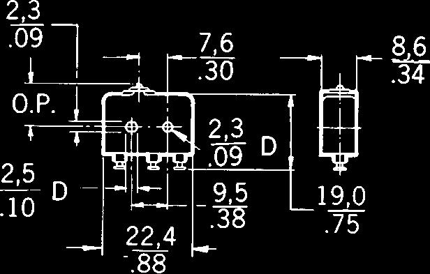
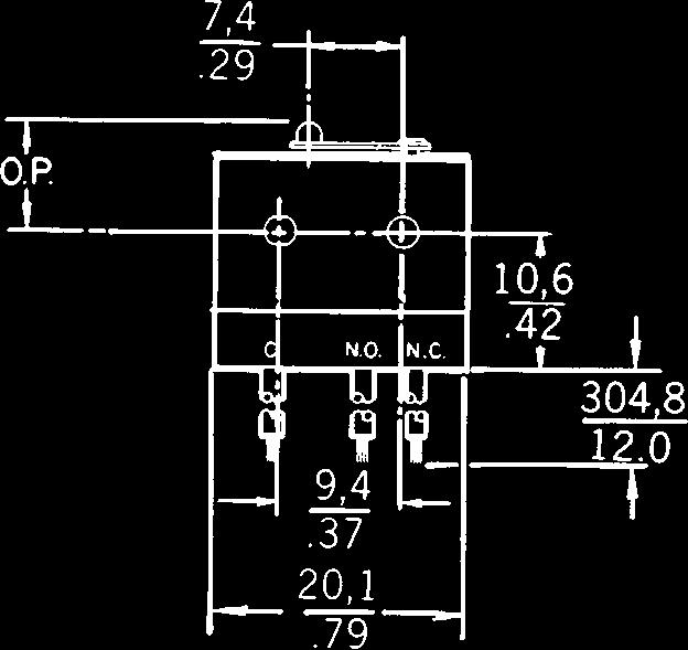
44 70 Honeywell Sensing and Control Forapplicationhelp:call Magnetic Blow-out MT Series FEATURES Arc resistant case Mechanical life of 100,000 operations 95% survival Temperature tolerance to +180 F (82 C) Mounting interchangeability with Z switches UL recognized GENERAL INFORMATION MT (single-pole ) magnetic blow-out switches are designed to switch high capacity (125 and 250 VDC) systems. An integral magnet around the contact gap protects the contacts by deflecting the arc. Vents between the cover and housing allow the hot gas to escape. These switches are designed for the control of DC motors, solenoids, etc. ELECTRICAL RATING Circuitry unless otherwise noted in order guide K Electrical Data and UL Codes Rating established with switch non-polarized 10 amps, 125 vac or vdc; 1/4 hp, 125 vac or vdc. UL Code L 168 Non-polarized: 10 amps res. or 1/4 hp, 125 vdc; 3 amps max. res. 250 vdc. Polarized*: 10 amps res. or 1/2 hp, 125 vdc; 3 amps max. res., 250 vdc. *To polarize, connect negative side of line to common terminal. To achieve the same effect, mount switch with brass screws, using a non-magnetic barrier (at least 1 4 thick) between the switch and mounting surface. ORDER GUIDE AVAILABLE TERMINALS Solder (No listing designation) A NC.218 Screws will accept up to #12 wire. Characteristics: O.F. Operating Force; R.F. Release Force; P.T. Pretravel; O.T. Overtravel; D.T. Differential Travel; O.P. Operating Position. Electrical O.F. R.F. min. P.T. max. O.T. min. D.T. max. O.P. Data and newtons newtons mm mm mm mm Catalog Listing Recommended For UL Codes ounces ounces inches inches inches inches Dim. Dwg. Fig. 1 MT-4R-A28 Pin plunger SPDT 10 Amps K 3,34-5, ,39 5 1, , ,1-0, ,9±0,38.625±.015
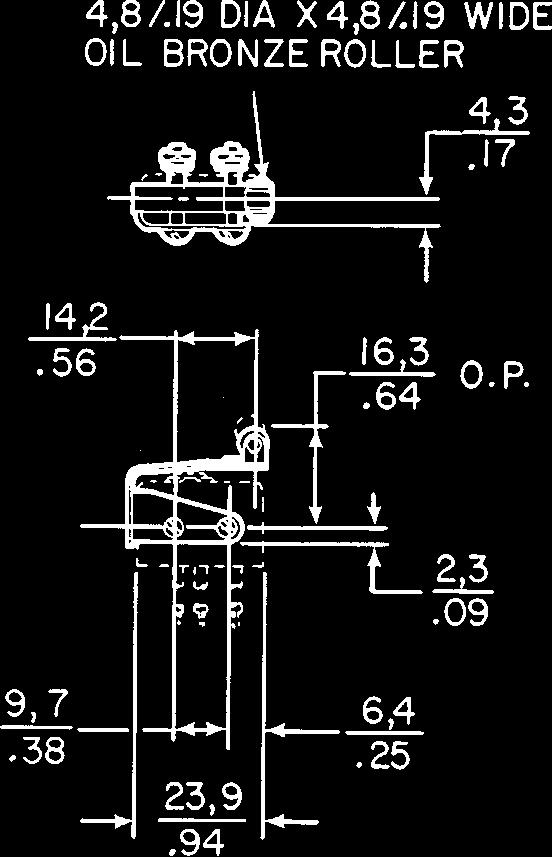
45 For application help: call Honeywell SensingandControl 71 Magnetic Blow-out Dim. Dwg. Fig. 2 Dim. Dwg. Fig. 3 Dim. Dwg. Fig. 4 Dim. Dwg. Fig. 5 ORDER GUIDE MT Series Electrical O.F. max. R.F. min. P.T. max. O.T. min. D.T. max. O.P.* Data and newtons newtons mm mm mm mm Catalog Listing Description UL Codes ounces ounces inches inches inches inches MT-4RV-A28 Straight lever 10 Amps K MT-4RV2-A28 MT-4RV22-A28 MT-4RL-A28 MT-4RL2-A inch (48,3mm) lever with hardened steel roller 1.03 inch (26,2mm) lever with hardened steel roller 1.95 inch (49,5mm) flexible leaf 1.82 inch (46,2mm) flexible leaf with hardened steel roller 10 Amps K 10 Amps K 10 Amps K 10 Amps K 0,56 2 0, , , , , , , , , , ,28 1 0,28 1 1, , , , max. 1, max. 2, , , , , , , , Except where stated * ±0,76 mm ±.030 in. Standard Courtesy of Steven Engineering, Inc.! 230 Ryan Way, South San Francisco, CA ! Main Office: (650) ! Outside Local Area: (800) !
46 72 Honeywell Sensing and Control Forapplicationhelp:call Magnetic Blow-out MOUNTING DIMENSIONS (For reference only) PIN PLUNGER STRAIGHT LEVER Fig. 1 Fig. 2 ROLLER LEVER FLEXIBLE LEAF Fig. 3 Fig. 4 FLEXIBLE ROLLER LEAF Fig. 5 Mounting holes accept pins or screws of.139 (3,53 mm) diameter. MT Series Courtesy of Steven Engineering, Inc.! 230 Ryan Way, South San Francisco, CA ! Main Office: (650) ! Outside Local Area: (800) !


47 32 Honeywell MICRO SWITCH Sensing and Control For application help: call Miniature CUT-A-WAY V3 MINIATURE BASIC SWITCH GENERAL INFORMATION V3 miniature basic switches feature high electrical capacity and long life. Their size and shape meet design requirements in all types of applications. AVAILABLE TERMINALS There is a choice of SPDT, SPNC, and SPNO circuitry. Many lever styles, contact materials, and terminal variations can be furnished. Contact the 800 number for ordering information. V3 Series FEATURES Low operating force to.53 ounce maximum Sensitive differential travel as low as.006 inch maximum Power load switching capability up to 25 amperes silver contacts Gold alloy crosspoint, silver cadmium, and other contact material for special applications Long mechanical life of 10,000,000 cycles 95% survival for V3-100, V3-1100, V3-2100, V Series Temperature tolerance up to +180 F (82 C) on standard construction High temperature construction for use up to +600 F (316 C) 3,1 mm mounting holes available UL recognized File #E12252, CSA certified File #LR41370 SOLDER SHORT SOLDER SCREW D8 QUICK CONNECT.188 wide.020 thick terminals.250 wide.032 thick terminals D9 Dimensions shown are for reference only Mounting torque: 2 inch pounds min. 5 inch pounds max. This section covers only 60 of our most popular V3 Series catalog listings. If you don t find what you re looking for, it s likely one of the approximately 850 other active V3 listings will meet your needs. Contact the 800 number. Courtesy of Steven Engineering, Inc.! 230 Ryan Way, South San Francisco, CA ! Main Office: (650) ! Outside Local Area: (800) !
48 For application help: call Honeywell MICRO SWITCH Sensing and Control 33 Miniature PIN PLUNGERS Dim. Dwg. Fig. 1 Dim. Dwg. Fig. 2 SIMULATED ROLLER Dim. Dwg. Fig. 3 Position. ORDER GUIDE by ascending electrical capability V3 Series Characteristics: O.F. Operating Force; R.F. Release Force; P.T. Pretravel; O.T. Overtravel; D.T. Differential Travel; O.P. Operating Electrical R.F. P.T. O.T. Data And O.F. min. max. min. D.T. O.P.** Catalog UL Code newtons newtons mm mm mm mm Listing Recommended For Page 20 ounces ounces inches inches inches inches V3-343-D8 General use. Gold alloy crosspoint contacts. 1 Amp 2,22 0,56 1,2 1,02 0,15-0,41 14,7 X 8 max V D8 Lowest force. 3 Amps 0,15 1,2 1,27 0,051-0,25 14,7 VV V D8 Lower force. 5 Amps 0,24 1,2 1,27 0,051-0,25 14,7 YY V D8 Most 5 amp applications. 5 Amps 2,22 0,56 1,2 1,02 0,15-0,41 14,7 ZZ V D8 General use. 10 Amps 0,72 max. 0,10 1,2 1,27 0,051-0,25 14,7 TT V D8 Low force. 10 Amps 0,50 max. 0,05 1,2 1,27 0,051-0,25 14,7 V V3-101-D8 Higher force. Most applications. V3-1-D8 Highest force. Up to 15.1 amps load handling with reduced life. V D8 High force. Up to 15.1 amps load handling. V D9 Up to 20 amps load handling V D9 Up to 25 amps load handling V (MS ) V (MS ) V (MS ) V3-129* MIL-S-8805 application requirements (SPDT) MIL-S-8805 application requirements (SPNC) MIL-S-8805 application requirements (SPNO) 11 Amps 2,22 0,56 1,2 1,02 0,15-0,41 14,7 T 8 max Amps 1,67-3,89 1,11 1,21 1,0 0,15-0,4 14,7 U ,1 Amps 1,47 max. 0,15 1,2 1,27 0,051-0,25 14,7 U Amps 0,63-1,22 0,20 1,2 1,27 0,25 14,7 AA max Amps 1,22-2,20 0,31 1,2 1,27 0,25 14,7 BB max Amps 1,67-3,89 1,11 1,2 1,02 0,15-0,41 14,7 UU Amps 1,67-3,89 1,11 1,2 1,02 0,15-0,41 14,7 UU Amps 1,67-3,89 1,11 1,2 1,02 0,15-0,41 14,7 UU Operating in 11 Amps 2,22 0,56 1,2 1,02 0,15-0,41 14,7 temperature to T 8 max F (150 C) V3-245* Operating in 10 Amps 2,78-6,95 1,67 1,2 1,02 0,15-0,41 14,7 temperature to +400 F (204 C) W *For actuators, contact MICRO SWITCH Sales Office. **Tolerances ±0.38 ±0.15 ORDER GUIDE Electrical Length of O.F. R.F. P.T. O.T. D.T. Data And Lever A max. min. max. min. max. O.P.* Catalog UL Code mm newtons newtons mm mm mm mm Listing Recommended For Page 20 inches ounces ounces inches inches inches inches V3L-1123-D8 General use. 10 Amps 32,6 0,39 0,05 2,54 2,03 0,76 18,5 TT V3L-2105-D8 Low force. 10 Amps 32,6 0,33 0,02 2,54 2,03 0,76 18,5 V V3L-121-D8 V3L-5-D8 V3L-3014-D8 High force. Most applications. Highest force. Up to 15.1 amps load handling with reduced life. High force. Up to 15.1 amps load handling. 11 Amps 32,6 1,11 0,14 3,18 1,57 0,81 18,5 T Amps 32,6 2,22 0,28 3,18 1,57 0,81 18,5 U Amps 32,6 0,94 0,07 2,54 1,90 0,76 18,5 U *±1.5 mm ±.060 in. Miniature/ Subminiature Courtesy of Steven Engineering, Inc.! 230 Ryan Way, South San Francisco, CA ! Main Office: (650) ! Outside Local Area: (800) !
49 34 Honeywell MICRO SWITCH Sensing and Control For application help: call Miniature STRAIGHT LEVERS Dim. Dwg. Fig. 4 Dim. Dwg. Fig. 4 Dim. Dwg. Fig. 4 Dim. Dwg. Fig. 4 ORDER GUIDE V3 Series Characteristics: O.F. Operating Force; R.F. Release Force; P.T. Pretravel; O.T. Overtravel; D.T. Differential Travel; O.P. Operating Position. Electrical Length of O.F. R.F. P.T. O.T. D.T. Data And Lever A max. min. max. min. max. O.P. Catalog UL Code mm newtons newtons mm mm mm mm Listing Recommended For Page 20 inches ounces ounces inches inches inches inches V3L-1105-D8 General use. 10 Amps 21,3 0,72 0,10 1,5 1,14 0,33 15,2±0,51 TT ±.020 V3L-2101-D8 V3L-101-D8 V3L-1-D8 V3L-3001-D8 Low force. Added overtravel. Higher force. Most applications. Highest force. Up to 15.1 amps load handling with reduced life. High force. Up to 15.1 amps load handling. 10 Amps 21,3 0,50 0,50 1,5 1,14 0,33 15,2±0,51 V ± Amps 21,3 2,50 0,56 1,5 1,02 0,41 15,2±0,51 T ± Amps 21,3 3,89 0,83 1,5 1,02 0,41 15,2±0,51 U ± Amps 21,3 1,47 0,15 1,5 1,02 0,28 15,2±0,51 U ±.020 V3L-1108-D8 General use. 10 Amps 35,6 0,39 0,04 2,79 2,29 0,76 15,2±1,5 TT ±.060 V3L-2102-D8 Low force. 10 Amps 35,6 0,31 0,02 2,79 2,29 0,76 15,2±1,5 V ±.060 V3L-104-D8 V3L-2-D8 V3L-3005-D8 Higher force. Most applications. Highest force. Up to 15.1 amps load handling with reduced life. High force. Up to 15.1 amps load handling. 11 Amps 35,6 1,11 0,14 3,18 2,29 1,27 15,2±1,5 T ± Amps 35,6 2,22 0,28 3,18 2,29 1,27 15,2±1,5 U ± Amps 35,6.86 0,06 3,05 2,29 0,81 15,2±1,5 U ±.060 V3L-2425-D8 Lower force. 5 Amps 59,4 0,07 5,08 4,06 1,4 15,2±2 YY ±.080 V3L-1122-D8 General use. 10 Amps 59,4 0,22 0,02 5,08 4,06 1,4 15,2±1,8 TT ±.070 V3L-2106-D8 Low force. 10 Amps 59,4 0,16 0,01 5,08 4,06 1,4 15,2±1,8 V ±.070 V3L-131-D8 V3L-6-D8 V3L-3013-D8 Higher force. Most applications. Highest force. Up to 15.1 amps load handling with reduced life. High force. Up to 15.1 amps load handling. 11 Amps 59,4 0,58 0,12 6,6 3,81 2,29 14,7±2 T ± Amps 59,4 1,11 0,14 6,95 3,81 2,29 14,35±1,5 U ± Amps 59,4 0,39 0,03 5,33 4,06 1,52 15,2±1,9 U ±.075 V3L-2472-D8 Lowest force. 3 Amps 69,45 0,03 5,97 5,08 1,60 15,2±2,54 VV ±.100 V3L-1124-D8 General use. 10 Amps 69,45 0,19 0,01 7,74 3,68 1,65 15,31±2,54 TT ±.100 V3L-145-D8 Most applications. 11 Amps 69,45 0,54 0,10 0,76 4,57 2,54 14,48±2,03 T ±.080 V3L-14-D8 Highest force. Up to 15.1 amps load handling with reduced life Amps 69,45 0,83 0,14 8,38 4,32 2,54 13,72±2,03 U ±.080 Courtesy of Steven Engineering, Inc.! 230 Ryan Way, South San Francisco, CA ! Main Office: (650) ! Outside Local Area: (800) !
50 For application help: call Honeywell MICRO SWITCH Sensing and Control 35 Miniature ROLLER LEVERS Dim. Dwg. Fig. 7 Dim. Dwg. Fig. 7 AUXILIARY ACTUATORS Dim. Dwg. Fig. 11 Dim. Dwg. Fig. 11 Dim. Dwg. Fig. 11 ORDER GUIDE V3 Series Electrical Length of Data And Lever A O.F. max. R.F. min. P.T. max. O.T. min. D.T. max. O.P. Catalog Recommended UL Codes mm newtons newtons mm mm mm mm Listing For Page 20 inches ounces ounces inches inches inches inches V3L-1117-D8 General use. 10 Amps 20,6 0,89 0,10 1,2 1,14 0,33 20,6±0,76 TT ±.030 V3L-2103-D8 Low force. 10 Amps 20,6 0,58 0,03 1,42 0,86 0,33 20,6±0,76 V ±.030 V3L-139-D8 Higher force. 11 Amps 20,6 2,22 0,56 1,5 1,02 0,41 20,6±0,76 Most applications. T ±.030 V3L-3-D8 Highest force Amps 20,6 3,89 0,83 1,52 1,02 0,41 20,6±0,76 Up to 15.1 amps U ±.030 load handling with reduced life. V3L-3003-D8 High force Amps 20,6 1,89 0,15 1,2 1,02 0,05-0,25 20,6±0,76 Up to 15.1 amps U ±.030 load handling. V3L-1101-D8 General use. 10 Amps 34 0,44 0,04 3,18 2,16 0,76 20,6±1,5 TT ±.060 V3L-2104-D8 Low force. 10 Amps 34 0,31 0,02 3,18 2,16 0,76 20,6±1,5 V ±.060 V3L-111-D8 Higher force. 11 Amps 34 1,11 0,14 3,18 2,16 1,27 20,6±1,5 Most applications. T ±.060 V3L-4-D8 Highest force Amps 34 2,22 0,28 3,18 2,16 1,27 20,6±1,5 Up to 15.1 amps U ±.060 load handling with reduced life. V3L-3004-D8 Higher force Amps 34 0,89 0,14 3,18 2,16 0,76 20,6±1,5 Up to 15.1 amps U ±.060 load handling. Characteristics: O.F. Operating Force; O.T. Overtravel; D.T. Differential Travel; R.F. Release Force; P.T. Pretravel; O.P. Operating Position; F.P. Free Position. * Characteristics taken with actuator assembled on Catalog Listing V3-1 switch as shown. ORDER GUIDE - SWITCHES ARE NOT INCLUDED WITH ACTUATORS Actuator Length A O.F. max R.F. min. P.T. max. O.T. min. D.T. max. O.P. F.P. max. Catalog mm newtons newtons mm mm mm mm mm Listing Description inches ounces ounces inches inches inches inches inches JV-1 Leaf type 21,3 3,34 1,11 1,19 0,79 0,41 15±0,38 16, ± JV-7 Long leaf 32,3 2,50 1,11 1,57 1,27 0,64 14,5±0,76 17, ± JV-5 Roller leaf 20,6 3,34 1,11 1,52 0,79 0,41 20,3±0,64 22, ± Miniature/ Subminiature Courtesy of Steven Engineering, Inc.! 230 Ryan Way, South San Francisco, CA ! Main Office: (650) ! Outside Local Area: (800) ! NOTE: Contact a MICRO SWITCH Sales Office for application assistance when actuators will be used at temperatures above 300 F (149 C).
51 36 Honeywell MICRO SWITCH Sensing and Control For application help: call Miniature AUXILIARY ACTUATORS Switches are not included with actuators Dim. Dwg. Fig. 14 Dim. Dwg. Fig. 14 Dim. Dwg. Fig. 14 Dim. Dwg. Fig. 11 Dim. Dwg. Fig. 17 Dim. Dwg. Fig. 17 V3 Series Characteristics: O.F. Operating Force; R.F. Release Force; P.T. Pretravel; O.T. Overtravel; D.T. Differential Travel; O.P. Operating Positon; F.P. Free Position * Characteristics taken with actuator assembled on Catalog Listing V3-100 switch as shown. ORDER GUIDE - SWITCHES ARE NOT INCLUDED WITH ACTUATORS Actuator Length A O.F. max. R.F. min. P.T. max. O.T. min. D.T. max. O.P. F.P. max. Catalog mm newtons newtons mm mm mm mm mm Listing Description inches ounces ounces inches inches inches inches inches JV-26 Long lever 44,5 0,39 0,06 8,33 3,58 4,75 12,7±3, ±.125 JV-20 Roller lever 19,1 0,83 0,14 4,78 1,57 1,98 19,5±1,4 23, ± JV-220 Roller lever 17,7 0,83 0,14 4,78 1,57 1,98 19,5±1,1 23, ± JV-30 One-way roller lever 20,6 3,34 1,11 2,03 0,51 0,38 25,7±0,76 27, ± JV-91** Tandem leaf 20,6 5,00 1,67 1,57 0,89 14,9±0,76 16, ± JV-82** Tandem roller leaf 20,6 5,00 1,67 1,57 0,89 20,5±0,76 21, ± NOTE: Contact the 800 number for application assistance when actuators will be used at temperatures above 300 F (149 C). ** Travel characteristics on tandem actuators vary with actual basic switch characteristics. These shown are typical for the assembly. A measurement is from the pivot point of lever to the point indicated on drawing. Courtesy of Steven Engineering, Inc.! 230 Ryan Way, South San Francisco, CA ! Main Office: (650) ! Outside Local Area: (800) !


 PIN PLUNGERS")


52 For application help: call Honeywell MICRO SWITCH Sensing and Control 37 Miniature MOUNTING DIMENSIONS (for reference only) PIN PLUNGERS Fig. 1 Fig. 2 SIMULATED ROLLER STRAIGHT LEVER ROLLER LEVER AUXILIARY ACTUATORS Fig. 3 Fig. 4 Fig. 7 Fig. 17 Fig. 11 Fig. 14 NOTE: Operate point dimensions taken at top of lever/roller. V3 Series Miniature/ Subminiature Courtesy of Steven Engineering, Inc.! 230 Ryan Way, South San Francisco, CA ! Main Office: (650) ! Outside Local Area: (800) !
53 BASIC SWITCHES V5 Series Miniature Straight /ever Typ e V5 Series are used for simple or 1, 6 precision on/off, end of limit, presence/absence, (P.T.) pressure, temperature and manual operato r A interface application needs. Voltage : 250 Vac Operating temperature : Standard -55 C to 85 C -67 F to 185 F High temperature -55 C to 150 C -67 F to 302 F Termination : 6,3 mm x 0,8 mm Quick connect (QC ) Contact type : Silver/silver cadmium oxid e Electrical rating : V5 A 20 A V5B/P/ R 16 A Type C V5C/ D 10 A V5S 22 A 3.2 Switching options : SPDT P I Single Pole Double Throw OPTIONS Top pin plunger i2,8r s.1-14,1-, APPROVALS REFERENC E CE ENEC V5A010C B CE, CSA, ENEC, UL V5BO10C8 3 CE, CSA, UL 4,8 mm x 0,5 mm OC V5BO10FB3 CE, ENEC Solder terminals V5BO10T 0 CE, ENEC High temperature V5B210C B CE, ENEC V5CO10B B CE, CSA. ENEC. UL 4,8 mm x 0,5 mm OC V5C010EB 3 CE, CSA. ENEC. UL Solder terminals V5CO10TB 3 CE, ENEC V5PO10CB 15, 3 (O.P.) APPROVALS CE, CSA, ENEC, U L 15, 3 (O.P.) APPROVAL S CE, ENE C Type APPROVAL S CE, ENEC 35,6 2 2 High temperature 59, 5 20, 6 (O.P. ) APPROVALS REFERENCE REFERENCE CE, CSA, ENEC. UL High temperature V5B210CB3 D V5CO10BB3B CE, CSA. ENEC. UL V5C010BB3 D REFERENC E V5B210CB1 C REFERENC E V5CO10BB1 G Type E APPROVALS REFERENC E CE. CSA, ENEC. UL Lever position 2 V5A010CB4 E CE. ENEC High temperature V5B210CB1 E 3, 2 (P.T.) 20.6 (O.P.) (Th a 20, APPROVALS SWITCHING OPTIONS REFERENC E CE ENEC SPNO V5DO30B B CE. ENEC SPNO V5R030C B CE, BEAB SPNC V5S020C B CE, BEAB SPNO V5SO30CB Honeywel l

54 38 Honeywell Sensing and Control Forapplicationhelp:call Miniature V7 Series CUTAWAY V7 MINIATURE BASIC SWITCH FEATURES Quick-connect and printed wiring board termination Proven V3 switching mechanism Physically interchangeable with existing V3 switches All existing V3 lever options available UL recognized File # E12252; CSA certified File # LR41370 International listings carry VDE approval Power load switching capability up to 21 amps Temperature tolerance 40 to 185 F ( 40 to 85 C) High temperature construction available 350 F APPLICABLE EUROPEAN SYMBOLS µ = microgap construction. (The measurement between open contacts is less than 3mm).** = alternating current (used with value of voltage source: 250V ). T = maximum rated use temperature; followed by the temperature value in C (example T 85). +++ = switch is rated for at least 50,000 cycles at its rated current. (Sometimes referred to as frequent operation.) 10(3) = first number represents resistive rating. Second number represents inductive (motor) rating. GENERAL INFORMATION The V7 Series is available in two versions, the Timesaver series and the International series. The Timesaver series is UL recognized and CSA certified. Timesaver series switches use readily available high-volume components to provide especially responsive delivery performance. The International V7 provides VDE approval in addition to UL recognition and CSA certification. The V7 offers a choice of four quick-connect and two printed wiring board terminal types. Three quick-connect types are offset to meet international 3mm spacing requirements and one is designed for use with molded connectors. Contact material choice includes gold alloy, silver alloy or silver for handling various electrical loads. There are two mounting hole sizes available. Standard.114 or 3mm to meet European design requirements. Terminal variations and switch dimensions of the European designed version conform to applicable DIN standards. These V7s mate with both standard domestic and international industry standard receptacles and connectors. The plastic enclosure meets VDE KC250 arc tracking requirement and is approvable under the Refrigeration Industry Taste and Odor test. OPERATING FORCES 175 grams (V rating only) 150 grams (Not applicable to Electrical Rating V) 75 grams (Not applicable to Electrical Rating C or V) 50 grams (Not applicable to Electrical Rating B, C, V) 25 grams (Not applicable to Electrical Rating B, C, E, V) 15 grams (Not applicable to Electrical Rating A, B, C, E, S, V) Mounting Torque: 2 inch pounds min. 5 inch pounds max. ELECTRICAL RATINGS A B C* D E F S V 5 amps, 125, 250 or 277 VAC; 1 10 hp, 250 VAC 11 amps and 1 3 hp, 125, 250 or 277 VAC; 1 2 amp, 125 VDC; 1 4 amp, 250 VDC; 4 amps, 125 VAC L X 6 amps; 1 8 HP 125, 250 or 277 VAC W 15.1 amps, 125, 250 or 277 VAC International Series Only 10 (3) V T85 µ 15.1 amps and 1 2 hp, 125, 250 or 277 VAC; 1 2 amp, 125 VDC; 1 4 amp, 250 VDC; 5 amps, 120 VAC L * Available only when specifying 150 gram operating force. NOTE: L denotes lamp load. 1 amp, 125 VAC 10 amps and 1 3 hp 125 or 250 VAC; 1 2 amp, 125 VDC; 1 4 amp, 250 VDC; 4 amps, 125 VAC L 5 (2) V T85 µ 3 amps, 125, 250 or 277 VAC; 1 10 hp, 250 VAC.1 amp, 125 VAC 21 amps 125, 250 or 277 VAC, 1 HP 125, 250, 277 VAC; 2 HP, 250, 277 VAC (4) 250V T85 µ 50E3 SPNO only **The microgap construction (M) means contact gap is less than 3mm. Therefore, these products are suitable for secondary circuit use but not primary circuit use which requires a 3mm gap.


55 For application help: call Honeywell SensingandControl 39 Miniature V7 Series AVAILABLE TERMINALS Quick-connect D8* E8 E9.187 Wide.187 Wide.250 Wide.020 Thick.020 Thick.032 Thick NOTE: D8 and E8 terminals are European approved when used with electrical ratings B, D, or E. E9 terminals are European approved when used with electrical ratings B, C, D, or E. Printed Wiring Board Printed wiring board terminals interface with snap-on receptacles and other components from AMPMODU interconnection system. Dimensions shown are for reference only. PO2 * International approving agencies will require that switches with these terminals have insulated receptacles or connector. PO1 PO7 Miniature/ Subminiature This section covers only 48 of our most popular V7 Series catalog listings. If you don t find what you re looking for, it s likely one of the approximately 300 other active V7 listings will meet your needs. Contact the 800 number.
56 Miniature TIMERSAVER SERIES PIN PLUNGERS ORDER GUIDE - SPDT* V7 Series Characteristics: O.F. Operating Force; R.F. Release Force; P.T. Pretravel; O.T. Overtravel; D.T. Differential Travel. Dim. Dwg. Fig. 1 STRAIGHT LEVERS Dim. Dwg. Fig. 2 Dim. Dwg. Fig. 5 Elect. O.F. max. R.F. min. P.T. max. O.T. min. D.T. Catalog Rating grams grams mm mm mm Listing P. 38 ounces ounces inches inches inches V7-1S17D8 1 Amp ,19 1,27 0,05-0,25 S V7-3S17E9 1 Amp ,19 1,27 0,05-0,25 S V7-3A17E9 5 Amps ,19 1,27 0,05-0,25 A V7-2B17D8 11 Amps ,19 1,27 0,05-0,25 B V7-2B17E9 11 Amps ,19 1,27 0,05-0,25 B V7-1C17D Amps ,19 1,27 0,05-0,25 C V7-9W1AE Amps ,19 1,27 0,25 W (350 F) max. V7-1V19E9 21 Amps ,19 1,27 0,05-0,25 V ORDER GUIDE - SPDT*.87 LEVER TIMESAVER SERIES V7-3S17D Amp ,52 0,89 0,33 S V7-1A17D Amps , ,38 A V7-2B17D Amps ,52 0,89 0,38 B V7-1C17E Amps ,52 0,89 0,36 C V7-1V19E Amps ,65 0,89 0,38 V LEVER TIMESAVER SERIES V7-3S17D Amp ,04 2,16 0,76 S V7-1A17E Amps ,04 1,52 0,76 A V7-1X2AD Amps ,40 0,76 0,38 X (350 F) V7-1B17D Amps ,04 1,7 0,68 B V7-1C17E Amps ,04 1,7 0,76 C V7-1V19E Amps ,3 1,78 0,76 V LEVER TIMESAVER SERIES V7-3S17D Amp ,97 3,0 1,27 S V7-2B17D Amps , ,27 B V7-1C17E Amps ,97 1,65 1,29 C V7-9W1AE Amps ,35 3,15 1,37 W (350 F) * For SPST (N.O. & N.C.) circuitry, contact the 800 number. NOTE: Catalog listings in V7 Order Guides have standard.114 mounting holes. For 3mm size holes, contact the 800 number. 40 Honeywell Sensing and Control Forapplicationhelp:call


57 For application help: call Honeywell SensingandControl 41 Miniature SIMULATED ROLLER LEVERS ORDER GUIDE - SPDT* 1.29 LEVER TIMESAVER SERIES V7 Series Characteristics: O.F. Operating Force; R.F. Release Force; P.T. Pretravel; O.T. Overtravel; D.T. Differential Travel. Elect. O.F. max. R.F. min. P.T. max. O.T. min. D.T. max. Catalog Rating grams grams mm mm mm Listing P. 38 ounces ounces inches inches inches 1.29 LEVER TIMESAVER SERIES Dim. Dwg. Fig. 3 Dim. Dwg. Fig. 4 Dim. Dwg. Fig. 7 ORDER GUIDE ACCESSORIES V7-1S17D Amp ,79 1,9 0,76 S V7-1B17D Amps ,79 1,52 0,76 B V7-1C17D Amps ,79 1,54 0,61 C ROLLER LEVER TIMERSAVER SERIES V7-2S17D Amp ,19 1,02 0,38 S V7-2B17D Amps ,3 1,04 0,3 B V7-1C17E Amps ,3 0,81 0,3 C V7-1V19E Amps ,42 0,81 0,33 V ROLLER LEVER TIMESAVER SERIES V7-3S17D Amp ,79 2,03 0,76 S V7-2A17D Amps ,92 1,52 0,64 A V7-1C17E Amps ,84 1,63 0,64 C V7-1V19E Amps ,07 1,65 0,76 V * For SPST (N.O. & N.C.) circuitry, contact the 800 number. NOTE: Catalog listing in V7 Order Guides have standard.114 mounting holes. For 3mm size holes, contact the 800 number. Catalog Listing Description Catalog Listing Description 15PA176-V7 Connector/Receptacle packet - Includes 25 connectors and 75 receptacles with 18, blue 16 gauge PVC insulated, stranded wire. (To be used with D8 terminals only). 15PA177-V7 Insulator packet (500 pcs.).018 thick varnished fiberglass. Miniature/ Subminiature 15PA260 Plunger boot seal. Elastomer dust and splash resistant plunger seal. Dimensions shown are for reference only.
58 42 Honeywell Sensing and Control Forapplicationhelp:call Miniature INTERNATIONAL SERIES PIN PLUNGER ORDER GUIDE - SPDT* INTERNATIONAL SERIES V7 Series Characteristics: O.F. Operating Force; R.F. Release Force; P.T. Pretravel; O.T. Overtravel; D.T. Differential Travel. Dim. Dwg. Fig. 1 STRAIGHT LEVERS Dim. Dwg. Fig. 5 SIMULATED ROLLER LEVERS Dim. Dwg. Fig. 3 ROLLER LEVERS Dim. Dwg. Fig. 4 Elect. O.F. max. R.F. min. P.T. max. O.T. min. D.T. Catalog Rating grams grams mm mm mm Listing P. 38 ounces ounces inches inches inches V7-1B11E9 11 Amps ,19 1,27 0,05-0,25 B V7-2B11D8 11 Amps ,19 1,27 0,05-0,25 B V7-2B11PO2 11 Amps ,19 1,27 0,05-0,25 B V7-3E11D8 10 Amps ,19 1,27 0,05-0,25 E V7-3E11E9 10 Amps ,19 1,27 0,05-0,25 E LEVER INTERNATIONAL SERIES V7-1B11E Amps ,79 2,28 0,76 B V7-2B11E Amps ,79 2,28 0,76 B V7-3E11D Amps ,79 2,28 0,76 E LEVER INTERNATIONAL SERIES V7-2B11D Amps ,54 1,9 0,76 B V7-3E11E Amps ,54 1,9 0,76 E ORDER GUIDE - SPDT*.81 LEVER INTERNATIONAL SERIES V7-2B11D Amps ,19 1,02 0,38 B V7-3E11D Amps ,19 1,02 0,38 E LEVER INTERNATIONAL SERIES V7-2B11E Amps ,54 2,16 0,76 B NOTE: Catalog listings in V7 Order Guides have standard.114 mounting holes. For 3mm size holes, contact the 800 number. Dim. Dwg. Fig. 7

 PIN PLUNGER Fig. 1 Fig.")

 Miniature/ Subminiature Fig.")
 (Style-048)")
 wide. Rollers are 0.")
59 For application help: call Honeywell SensingandControl 43 Miniature V7 Series MOUNTING DIMENSIONS (for reference only) PIN PLUNGER Fig. 1 Fig. 2 Straight Lever Fig. 3 Simulated Roller Fig. 4 Roller Lever (Style-002) (Style-263) (Style-201) Miniature/ Subminiature Fig. 5 Straight Lever Fig. 6 Straight Lever Fig. 7 Roller Lever (Style-022) (Style-048) (Style-207) NOTE: All levers are 0.17 (4,31 mm) wide. Rollers are 0.19 (4,82 mm) wide. NOTE: Operate point dimensions taken at top of lever/roller.
60 BASIC SWITCHES ZM, ZX, ZV and ZW Series Subminiatur e Basic Switche s ZM, ZX, ZV and ZW Series Subminiature are cost - effective devices used for simple on/off applications. These switche s combine small size and light weight with ample electrical capability an d long life. Plastic lever capability is available on the ZV Series. Straight /ever Electrical rating : Voltage : Operating temperature : Termination : Contact type : Switching options : ZM Series Approvals : Electrical rating : OPTIONS Top pin plunger Wln D_ ism m ~ , _ A, 3 A, 5 A or 10.1 A 125/250 Va c 25 C to 85 C [-13 F to 185 F] Quick connect, solder, PC B Gold or silve r SPDT UL/CS A 0.1 A, 5 A or 10.1 A TERMINATION ELECTRICAL RATING CONTACT TYPE REFERENC E Quick connect 5A silver ZM50E70AO 1 Solder 5A silver ZM50E1OA0 1 PCB 10.1 A silver ZM90G2OAO 1 Solder 0.1 A gold ZM10BI0A01 TERMINATION Quick connect Solder T1 ~w1 ll' `rj I 9S I ELECTRICAL RATIN G 5 A 5A Simulated roller lever TERMINATION Quick connec t Solder 0205' CONTACT TYPE REFERENCE silver ZM50E70DO 1 silver ZM50E10DO ELECTRICAL RATING CONTACT TYPE REFERENC E 5A silver ZM50E70EO1 5A silver ZM50E10EO1 Honeywel l g
61 _ 92 BASIC SWITCHES ZX Series Simulated roller leve r Approvals : Electrical rating : U L/C S A 0.1 A or 3 A L OPTIONS Top pin plunger 0 1 I I I TERMINATION PCB Solder Straight lever ELECTRICAL RATING CONTACT TYPE 3A silve r 0.1 A gold REFERENCE ZX40E30AO1 ZX10C10AO TERMINATION PCB Solder ZV Series Approvals : Electrical rating : OPTIONS I _ L 5.08 I _ Top pin plunge r ELECTRICAL RATING 3A 3A Ig) D dra o 0 oo' I t o P.05 1 '' '0 e -121 J0 CONTACT TYP E silve r silver al Pt: J -I ~ REFERENC E ZX40E30EO 1 ZX40E10E0 1 UL/ENE C 0.1 A, 5 A or 10.1 A 0 TERMINATIO N PCB Solder ELECTRICAL RATING CONTACT TYPE 3 A silve r 3A silver REFERENCE ZX40E30001 ZX40E10001 TERMINATIO N PC B Solde r Quick connect ELECTRICAL RATING CONTACT TYPE REFERENC E 5A silver ZV50E20A01 5 A s3vvr ZV50E10A A gold ZVI OB70AO 1 Honeywel l IA
62 BASIC SWITCHES Straight lever ZW Sealed Series S Approvals : Electrical rating : OPTIONS UL/ENE C 0.1 Aor5A ~ L- Ir~ - ft. Top pin plunger ~~S~ A 02' 5 I +0. 1!-,02.4-,O ' ' I TERMINATION ELECTRICAL RATING CONTACT TYPE REFERENC E Solder 5A silver ZV50E10B0 1 Quick connect 5A silver ZV50E Roller lever TERMINATION PCB Quick connect I II 2Io C / ELECTRICAL RATING CONTACT TYPE REFERENC E 5A silver ZV50E20FO1 5A silver ZV50E70FO1 90, I.2 3z TERMINATION ELECTRICAL RATING CONTACT TYPE Solder 5 A silve r Straight lever REFERENC E ZW50F15AD C TERMINATION ELECTRICAL RATING CONTACT TYPE REFERENC E Solder 0.1 A gold ZW1OE15CD1 Honeywell g
63 (t ( 5 Honeywell m Roller leve r I S Y 1 0} O S a TERMINATION Wire leads CON : BLACK NO,CYAN 5.2 I NC_ 0R A Y ELECTRICAL RATING CONTACT TYPE 0.1 A gold REFERENCE ZW10E90FW 1 J01.0.BJ
64 44 Honeywell Sensing and Control Forapplicationhelp:call Miniature Double-break TB Series Dim. Dwg. Fig. 1 Dim. Dwg. Fig. 2 ORDER GUIDE FEATURES Power load switching capability up to 10 amperes Motor handling capacity of 1 2 horsepower, 125 VAC Two- and four-circuit double-break Several auxiliary actuators Choice of terminal styles UL recognized, CSA certified Momentary action GENERAL INFORMATION TB miniature switches are basic doublebreak units which offer a means of controlling isolated circuits. Each circuit can be driven by independent voltage sources. These switches find many uses in modern control systems because of their circuitry. The terminals of two- and four-circuit double break switches must be wired to identical voltage sources and the same polarity so that a voltage potential is not set up between adjacent terminals. A voltage potential between adjacent terminals could promote dielectric breakdown at high energy levels. The loads should be on the same sides of the line. Characteristics: O.F. Operating Force; R.F. Release Force; P.T. Pretravel; O.T. Overtravel; D.T. Differential Travel; O.P. Operating Position. Electrical Data And O.F. R.F. min. P.T. max. O.T. min. D.T. O.P.** Catalog UL Code newtons newtons mm mm mm mm Listing Description Page 20 ounces ounces inches inches inches inches 1TB1-1 Two-circuit, doublebreak 10 Amps 1,95-3,61 1,11 1,52 0,25 0,25-0,64 11,7 end screw terminals Z TB1-2 Two-circuit, doublebreak end solder terminals 10 Amps 1,95-3,61 1,11 1,52 0,25 0,25-0,64 11,7 Z Dim. Dwg. Fig. 3 1TB1-3 Two-circuit, doublebreak front solder terminals 10 Amps 1,95-3,61 1,11 1,52 0,25 0,25-0,64 11,7 Z TB5-3 Four-circuit, doublebreak front solder terminals 10 Amps 5,56-10,0 2,22 1,78 0,25 0,64-1,14 4,70 Z Dim. Dwg. Fig. 4 * ±0,38 mm ±.015 in


 Catalog Listing")

65 For application help: call Honeywell SensingandControl 45 Miniature Double-break TB Series AUXILIARY ACTUATORS For use with 1TB1-1 and 1TB1-2 switches ORDER GUIDE JT-1 JT-5 Switches are not included with the actuators. MOUNTING DIMENSIONS (For reference only) Catalog Listing JT-1 JT-5 Leaf actuator Roller leaf actuator Description Fig. 1 Fig. 2 Miniature/ Subminiature Fig. 3 Fig. 4


66 For application help: call Honeywell SensingandControl 47 Standard STANDARD BASIC SWITCH CUT-A-WAY The cut-a-way shown is representative of the standard basic switches described in this catalog. GENERAL INFORMATION MICRO SWITCH standard basic switches are precision snap-action mechanisms enclosed in accurately molded plastic cases. These switches are carefully manufactured and thoroughly inspected. They are industry known for their compactness, light weight, accurate repeatability and long life. MOUNTING DIMENSIONS Mounting dimensions are included at the end of each product section. They are shown in English and metric equivalents. These dimensions are for reference only. For exacting layout work, request an engineering layout work, request an engineering drawing from the 800 number. Mounting holes for Types BZ, BM, BA, BE, DT, MT, and 6AS switches accept pins or screws of.139 inch (3,53 mm) diameter. RECOMMENDED TORQUE (max.) Mounting screws...3in./lbs.* Terminal screws...4in./lbs. Panel mount bushing...4-6in./lbs. * Note: Tightening mounting screws above 3 in./lbs. changes operating characteristics and increases the possibility of cracking the case. The type BZ switch design meets most applications needs. Modifications of the standard silver contact design and material, spring configuration, and plunger locations give the type BM, BA and BE switches greater electrical load handling capacity. Other changes in materials and switch design provide operating characteristics, temperature tolerances, and sealing to cover a wide range of special requirements. GENERAL SWITCH IDENTIFICATION First letter in catalog listing designates: B = W = single-throw (normally closed) Y = single-throw (normally open) Second letter in catalog listing designates: Z = Standard 15-amp version M = 22-amp version A = Standard 20-amp version E = 25-amp version BZ/BA Series FEATURES Operating force as low as 4 oz. (113 grams) maximum Sensitive differential travel as low as.0002 to.0003 inches (0,005 to 0,008 mm) Power load switching capability to 25 amperes Motor handling capacity to 2 horsepower at 250 VAC Long mechanical life High temperature constructions for up to +400 F (204 C) Momentary or maintained contact action Alloy contacts available for special application needs Variety of integral actuators Variety of auxiliary actuators Variety of terminal designs Optional sealed plunger and cover Stainless steel snap spring available Military standard construction available with over 50 listings on the MIL- S-8805 Qualified products list UL recognized, CSA certified Characteristics as stated are taken at normal room temperature and humidity. These may vary as temperature and humidity conditions differ. This section covers only over 100 of our most popular BZ/BA type Series catalog listings. If you don t find what you re looking for, it s likely one of the approximately 1800 other active listings will meet your needs. Contact the 800 number. Standard UL/CSA Our basic switches are Component Recognized by Underwriters Laboratories, Inc. and certified by Canadian Standards Association. The BA, BZ, and BM line is covered as Special Use Switches to UL Standard1054; the BE line is covered as an Industrial Motor Controller to UL Standard 508. Agency File References are: BA UL File E12252, issued BM UL File E12252, issued BZ UL File E12252, issued BE-1,2,5 UL File E22779, Vol. 4, Sec. 1 BE-R UL File E22779, Vol. 4, Sec. 2


 Use up to #14 wire D6.")
 thick quick-connect ACTUATORS")


 T Bottom facing 218 screw")


67 48 Honeywell Sensing and Control Forapplicationhelp:call Standard BZ/BA Series AVAILABLE TERMINALS Most of the BZ/BA catalog listings have A2 type terminals. Several other terminal styles are shown and others are available. Specific information should be requested from the 800 number or local Authorized Distributor. Solder (No suffix) Use up to #14 wire D6.250 (6,35 mm) wide.032 (0,81 mm) thick quick-connect ACTUATORS BA, BE, BM and BZ standard basic switches use the actuators described. Pin plunger; in-line motion A2 Bottom facing 6-32 NC.218 screw with cup washers A4 (Same as A2 except #8 screws) T Bottom facing 6-32 NC.218 screw with Sems lockwashers P4 Side facing screw with cup washers D5.250 (6,35 mm) wide.030 (7,62) thick quick-connect PC2 Self lifting pressure plate terminals and plastic barriers for added dielectric protection Overtravel plunger; in-line applications requiring additional overtravel Added overtravel in a panel mount roller plunger; Actuation by cams Leaf; Low-force, slow moving cams or slides Roller lever; Very low force, fast moving cams Roller leaf; Low-force, large movement actuation Lever; Very low force, slow cams and slides Added overtravel in a panel-mount plunger; Heavy-duty in-line applications or slow cams. Cam rise should not exceed 30
68 For application help: call Honeywell SensingandControl 49 Standard BZ/BA Series Characteristics: O.F. Operating Force; R.F. Release Force; P.T. Pretravel; O.T. Overtravel; D.T. Differential Travel; O.P. Operating Position. ORDER GUIDE by ascending electrical capability PIN PLUNGER BZ/BA TYPE Dim. Dwg. Fig. 1 SEALED TYPE Dim. Dwg. Fig. 2 BA/BE TYPE Dim. Dwg. Fig. 3 Electrical Data And O.F. R.F. min. P.T. max. O.T. min. D.T. O.P.** Catalog UL Codes newtons newtons mm mm mm mm Listing Recommended For Page 46 ounces ounces inches inches inches inches BZ-2R72-A2 BZ-2R A2 BZ-2R244-A2 Applications requiring gold alloy contacts Gold alloy contacts Dustproof and splash resistant seal Operating in temp. to +400 F (204 C) for 100 hours 1 Amp 2,5-3,61 1,11 0,38 0,13 0,01-0,05 15,88 P Amp 2,22-4,17 1,11 0,13 0,01-0,06 15,88 P Amps 2,5-3,61 1,11 0,38 0,13 0,01-0,05 15,88 B BZ-R21-A2 Lower force 10 Amps 1,11 0,7 0,30 0,13 0,005-0,013 15,88 C BZ-2R-A2 Most applications 15 Amps 2,5-3,61 1,11 0,38 0,13 0,01-0,05 15,88 SPDT A WZ-2R-A2 SPST (normally 15 Amps 2,5-3,61 1,11 0,38 0,13 0,01-0,05 15,88 closed) A YZ-2R-A2 SPST (normally open) 15 Amps 2,5-3,61 1,11 0,38 0,13 0,01-0,05 15,88 A BZ-R-A2 Less differential travel 15 Amps 1,95-2,5 1,11 0,30 0,13 0,005-0,008 15,88 D BZ-R19-A2 Best repeatability 15 Amps 1,95-3,34 1,11 0,30 0,13-0,2 0,005-0,02 16,26 D BZ-2R24-A2 Operating in temp. to 15 Amps 2,5-3,61 1,11 0,38 0,13 0,01-0,05 15, F (121 C) A BZ-2RT04 (8805/1-004) BZ-2R05-A2 BZ-2R5551-A2 BZ-2R55-A2-S BA-2R-A2 BA-2R24-A2 BM-1R-A2 BE-2R-A4 MIL-S-8805 application requirements Best stability under varying humidity Dustproof and splash resistant seal Best service for sealed construction. Stainless steel internal snap spring. Up to 20 ampere load handling Operating in temperature to +250 F (121 C) Up to 22 ampere load handling Up to 25 ampere load handling 15 Amps 2,5-3,61 1,67 0,38 0,13 0,01-0,05 15,88 A Amps 2,5-3,61 1,11 0,38 0,13 0,01-0,05 15,88 A Amp 2,5-4,17 1,11 0,13 0,01-0,06 15,88 A Amps 2,5-4,17 1,11 0,13 0,01-0,06 15,88 A Amps 3,89-6,12 2,78 1,27 0,25 0,05-0,19 16,26 G Amps 3,89-6,12 2,78 1,27 0,25 0,05-0,19 16,26 G Amps 1,95-2,78 1,11 0,38 0,13 0,013-0,025 15,88 F Amps 3,89-6,12 2,78 1,27 0,25 0,05-0,19 16,26 H Standard Dim. Dwg. Fig. 4 BZ-RX WA-1RX-A4 *Reset characteristics. Manual reset (maintained contact) applications, solder terminals Manual reset SPST- NC, A4 terminals 15 Amps 1,95-2,5 0,30 0,13 15,88 E ,56-2,78* 0,38* Amps 5,56 0,25 0,20 16,26 W ,95* 27,9* All catalog listings shown are not necessarily stock items. Stocking depends on sales experience. Except where stated ** ±0,38mm ±.015 in. Auxiliary actuators see p
69 50 Honeywell Sensing and Control Forapplicationhelp:call Standard BZ/BA Series OVERTRAVEL PLUNGER Dim. Dwg. Fig. 11 Dim. Dwg. Fig. 12 Dim. Dwg. Fig. 13 ORDER GUIDE Characteristics: O.F. Operating Force; R.F. Release Force; P.T. Pretravel; O.T. Overtravel; D.T. Differential Travel; O.P. Operating Position. Electrical Data and O.F. R.F. min. P.T. max. O.T. min. D.T. O.P.* UL Codes newtons newtons mm mm mm mm Catalog Listing Recommended For Page 46 ounces ounces inches inches inches inches BZ-2RD72-A2 BZ-2RD-A2 BZ-2RD24-A2 BM-1RD-A2 BZ-2RDS A2 BZ-2RDS5551-A2 BA-2RB-A2 BE-2RB-A4 BZ-2RS72-A2 BZ-2RS-A2 BZ-2RS24-A2 BZ-2RST04 (M8805/1-012) Applications requiring gold alloy contacts Added overtravel. For manual operation and slow 20 (max) cam rise Operating in temperature to +250 F (121 C) Up to 22 ampere load handling Applications requiring gold alloy contacts plus dustproof and splash resistant seal Dustproof and splash resistant seal Up to 20 ampere load handling Up to 25 ampere load handling Applications requiring gold alloy contacts Added overtravel. For in-line operation and with JR auxiliary actuators 1 Amp P 15 Amps A 15 Amps A 22 Amps F 1 Amp P 15 Amps A 20 Amps G 2,5-3, ,5-3, ,5-3, ,95-2, ,61-5, ,61-5, ,89-6, Operating in temperature to +250 F (121 C) MIL-S-8805 application requirements Dim. Dwg. Fig. 14 BZ-RSX Manual reset solder terminals BM-1RS-A2 Up to 22 ampere load handling 25 Amps H 1 Amp P 15 Amps A 15 Amps A 15 Amps A 15 Amps E 22 Amps F 3,89-6, ,5-3, ,5-3, ,5-3, ,5-3, ,95-2, ,95-2, ,11 4 1,11 4 1,11 4 1,11 4 0, , , , ,11 4 1,11 4 2, , ,11 4 1,11 4 1,11 4 1,67 6 1,11 4 1, , , , , , , , , , , , , , , , , , , , , , ,01-0, ,01-0, ,01-0, ,013-0, ,01-0, ,01-0, ,05-0, ,05-0, ,01-0, ,01-0, ,01-0, ,01-0, ,013-0, , , , , , , , , , , , , , , BZ-2RS A2 Applications requiring gold alloy contacts plus dustproof and splash resistant seal 1 Amp P 2,5-4, ,11 4 1, ,01-0, , Dim. Dwg. Fig. 15 BZ-2RS5551-A2 Dustproof and splash resistant seal 15 Amps A 2,5-4, ,11 4 1, ,01-0, , *±0,51 mm ±.020 in.
70 For application help: call Honeywell SensingandControl 51 Standard BZ/BA Series OVERTRAVEL PLUNGER Dim. Dwg. Fig. 16 BZ/BM TYPE Dim. Dwg. Fig. 17 BA TYPE Dim. Dwg. Fig. 18 Dim. Dwg. Fig. 19 ORDER GUIDE Electrical Data and O.F. R.F. min. P.T. max. O.T. min. D.T. O.P.** UL Codes newtons newtons mm mm mm mm Catalog Listing Recommended For Page 46 ounces ounces inches inches inches inches BZ-2RQ-A2 BZ-2RQ24-A2 BZ-2RQ172-A2 BZ-2RQ1-A2 BZ-2RQ1T04 (M8805/1-020) BZ-2RQ124-A2 BZ-2RN702 BZ-RQ1X BA-2RQ1-A2 BM-1RQ1-A2 BZ-2RQ1872-A2 BZ-2RQ18-A2 BZ-2RQ1824-A2 BZ-2AQ18T1 BM-1RQ18-A2 Added overtravel. For manual in-line operation and for slow 30 (max) rise cams Operating in temperature to ±250 F (121 C) Applications requiring gold alloy contacts BZ-2RQ-A2 type applications with panel mount MIL-S-8805 application requirements Operating in temperature to ±250 F (121 C) Furnished with unassembled seal boot. Manual reset. Solder terminals Up to 20 ampere load handling Up to 22 ampere load handling Applications requiring gold alloy contacts 15 Amps A 15 Amps A 1 Amp P 15 Amps A 15 Amps A 15 Amps A 15 Amps X 15 Amps E 2,5-3, ,5-3, ,5-3, ,5-3, ,5-3, ,5-3, ,5-3, ,67-2, Added overtravel. Roller plunger for rapid cam (30 max) rise and slide operation. Panel mount Operating in temperature to ±250 F) (121 C) Double-break circuitry Up to 22 ampere load handling 20 Amps G 22 Amps F 1 Amp P 15 Amps A 15 Amps A 15 Amps T 22 Amps F 3,89-6, ,95-2, ,5-3, ,5-3, ,5-3, ,89-6, ,95-2, ,11 4 1,11 4 1,11 4 1,11 4 1,67 6 1,11 4 1,11 4 2, ,11 4 1,11 4 1,11 4 1,11 4 1,11 4 1,11 4 0, , , , , , , , , , , , , , , , , , , , , , , , , , , , , , ,01-0, ,01-0, ,01-0, ,01-0, ,01-0, ,01-0, ,01-0, ,05-0, ,013-0, ,01-0, ,01-0, ,01-0, ,03-0, ,013-0, ,10±0, ± ,10±0, ± , , , , ,4±0, ± ,42±1,14.922±.045 7,14*.281* 21, , ,32±1, ± ,32±1, ± ,32±1, ± ,35±1, ± ,32±1, ±.045 Standard BZ-2RQ181-A2 Applications requiring roller plunger 90 to major axis of switch 15 Amps A 2,5-3, ,11 4 0, , ,01-0, ,32±1, ±.045 Dim. Dwg. Fig. 20 * Reset characteristics. Except where stated ** ±0,76 mm ±.030 in.
71 52 Honeywell Sensing and Control Forapplicationhelp:call Standard STRAIGHT LEVER ORDER GUIDE BZ/BA Series Characteristics: O.F. Operating Force; R.F. Release Force; P.T. Pretravel; O.T. Overtravel; D.T. Differential Travel; O.P. Operating Position. BZ/BM TYPE Dim. Dwg. Fig. 21 BA TYPE Dim. Dwg. Fg. 23 ADJUSTABLE Electrical Data and O.F. max. R.F. min. P.T. max. O.T. min. D.T. O.P.** Recommended UL Codes newtons newtons mm mm mm mm Catalog Listing For Page 46 ounces ounces inches inches inches inches BZ-2RW8072-A2 BZ-2RW A2 BZ-2RW8244-A2 BZ-RW8435-A2 BZ-2RW876T BZ-2RW80-A2 BZ-2RW84-A2 BZ-2RW A2 BZ-2RWT04 (M8805/1-044) BZ-2RW824-A2 BZ-RW80X BZ-2RW863-A2 BA-2RV-A2 Applications requiring gold alloy contacts Best stability under varying humidity. Gold alloy contacts with seal Operating in temp. to +400 F (204 C) for 100 hours Lowest operating force (without external return spring) 1.25 inch lever requirements 2.5 inch lever requirements Lower force (without external return spring) Dustproof and splash resistant seal MIL-S-8805 application requirements Operating in temperature to +250 F (121 C) Manual reset solder terminals 1 Amp P 1 Amp P 5 Amps B 10 Amps I 15 Amps A 15 Amps A 15 Amps A 15 Amps A 15 Amps A BM-1RW84-A2 BE-2RV-A4 * Reset characteristics. 6 inch lever requirements Up to 20 ampere load handling Up to 22 ampere load handling Up to 25 ampere load handling 15 Amps A 15 Amps E 15 Amps A 20 Amps G 22 Amps F 25 Amps H 0, , , , ,67 6 0, ,28 1 0, ,28-0, , , , , , , , , , , , , , , ,28 1 0, ,28 1 0, , , , , , , , , , , , , , , , , ,18-1, ,18-1, ,18-1, ,08-0, ,10-0, ,18-1, ,18-1, ,18 1, , ,18-1, , , , , , , , , , , , , ,38* 7,14* , , , , ,46-3, , ,13-0, , max. 19,1±1,52.750± , , ,1.750 BZ-2RW899-A2 Adjustable operating point (17 mm to 22 mm).670 to Amps A , ,18-1, ,02-22, Dim. Dwg. Fg. 22 BZ-2RM-A2 17 mm From O.P..670 in. Reverse acting actuator (switch plunger depressed in free position) 15 Amps A 1,67 6 0,28 1 5, , ,10-0, ,1.750 Except where stated ** ±0.76 mm ±.030 in. Dim. Dwg. Fig. 24
72 For application help: call Honeywell SensingandControl 53 Standard BZ/BA Series SIMULATED ROLLER ORDER GUIDE Dim. Dwg. Fig. 27 Electrical O.F. R.F. P.T. O.T. Data And max. min. max. min. D.T. O.P.** Catalog UL Code newtons newtons mm mm mm mm Listing Recommended For Page 46 ounces ounces inches inches inches inches BZ-2RW80147-A2 BZ-2RW80196-A inch (26,7 mm) (simulated roller) lever applications 1.90 inch (48,3 mm) (simulated roller) lever applications ROLLER LEVER BZ-2RW82272-A2 Applications requiring gold alloy contacts BZ-2RW A2 Applications requiring gold alloy BZ/BM TYPE contacts plus dustproof and splash resistant seal BZ-2RW822-A inch (26,7 mm) (steel roller) lever applications Dim. Dwg. Fig. 25 Dim. Dwg. Fig. 28 BA/BE TYPE 15 Amps 1,67 0,42 2,39 0,08-0,51 30,17 A Amps 0,97 0,21 3,96 0,10-1,0 30,17±0,76 A ± Amp 1,67 0,42 2,39 0,08-0,51 30,17 P Amp 1,67 0,42 2,39 0,08-0,51 30,17 P Amps 1,67 0,42 2,39 0,08-0,51 30,17 A BZ-2RW8222-A2 Roller turned Amps 0,7-1,81 0,35 3,58 0,08-0,51 30,75 A max BZ-2RW82224-A2 Operating in 15 Amps 1,67 0,42 2,39 0,08-0,51 30,17 temperature to +250 F (121 C) A BZ-2RW A2 Dustproof and 15 Amps 1,67 0,42 2,39 0,08-0,51 30,17 splash resistant seal A BZ-2RW82255-A2-S Best service for 15 Amps 1,67 0,42 2,39 0,08-0,51 30,17 sealed construction. A Stainless steel internal snap spring. BA-2RV22-A2 Up to 20 ampere 20 Amps 1,67 0,42 6,35 0,76 1,14 29,77 load handling G max BM-1RW822-A2 Up to 22 ampere 22 Amps 1,67 0,42 2,39 0,025-0,33 30,17 load handling F BE-2RV22-A4 Up to 25 ampere 25 Amps 1,67 0,42 6,35 0,76 1,14 29,77 load handling H max BZ-2RW82299-A2 BZ-2RW8299-A2 Adjustable operating point. Roller lever 1.05 inch (26,7 mm) Adjustable operating point. Roller lever 1.90 inch (48,3 mm) 15 Amps 1,67 0,42 1,02 0,08-0,51 29,77-30,56 A Amps 0,97 0,21 2,16 0,10-1,0 29,2-31,5 A Standard Dim. Dwg. Fig. 26 Except where stated * ±0,38 mm ±.015 in.
73 54 Honeywell Sensing and Control Forapplicationhelp:call Standard BZ/BA Series ROLLER LEVER ORDER GUIDE Characteristics: O.F. Operating Force; R.F. Release Force; P.T. Pretravel; O.T. Overtravel; D.T. Differential Travel; O.P. Operating Position. BZ/BM TYPE Dim. Dwg. Fig. 29 BA/BE TYPE Dim. Dwg. Fig. 30 Dim. Dwg. Fig. 31 Dim. Dwg. Fig. 32 Electrical O.F. R.F. P.T. O.T. Data And max. min. max. min. D.T. O.P.* Catalog Recommended UL Code newtons newtons mm mm mm mm Listing For Page 46 ounces ounces inches inches inches inches BZ-2RW A2 BZ-2RW82-A2 BZ-2RW A2 BZ-2RW8224-A2 BA-2RV2-A2 BM-1RW82-A2 Applications requiring gold alloy contacts, plus dustproof, and splash resistant seal 1.90 inch (48,3 mm) (steel roller) lever applications Dustproof and splash resistant seal Operating in temperature to +250 F (121 C) Up to 20 ampere load handling Up to 22 ampere load handling 1 Amp 0,97 0,21 3,96 0,10-1,0 30,17±0,76 P ± Amps 0,97 0,21 3,96 0,10-1,0 30,17±0,76 A ± Amps 0,97 0,21 3,96 0,10-1,0 30,17±0,76 A ± Amps 0,97 0,21 3,96 0,10-1,0 30,17±0,76 A ± Amps 0,97 0,14 11,89 1,52 2,16 30,17±0,76 G ± Amps 0,97 0,21 3,96 0,08-0,56 30,17±0,76 F ±.030 BE-2RV2-A4 Up to 25 ampere load 25 Amps 0,97 0,14 11,89 1,52 2,16 30,17±0,76 handling H max ±.030 NOTE: For adjustable operate point and simulated roller lever switches, refer to previous page. BZ-RW922-A2 Best repeatability and O.P. stability BZ-2RW826-A2 One-way roller (9,4 mm 3,8 mm).37 dia..15 wide roller BZ-2RW825-A2 One-way roller (4,83 mm 4,83 mm).19 dia..19 wide roller 10 Amps 3,34 1,11 0,38 2,54 0,013-0,025 31,37 I Amps 1,67 0,42 2,39 0,08-0,51 41,34 A Amps 2,22 0,42 1,52 0,38 28,96 A Except where stated * ±0,38 mm ±.015 in.
74 For application help: call Honeywell SensingandControl 55 Standard BZ/BA Series FLEXIBLE LEAF ORDER GUIDE BZ TYPE Dim. Dwg. Fig. 33 BA/BE TYPE Dim. Dwg. Fig. 34 FLEXIBLE ROLLER LEAF BZ TYPE Dim. Dwg. Fig. 35 BA/BE TYPE Dim. Dwg. Fig. 36 Electrical Data and O.F. max. R.F. min. P.T. max. O.T. min. D.T. max. O.P.** UL Codes newtons newtons mm mm mm mm Catalog Listing Recommended For Page 46 ounces ounces inches inches inches inches BZ-2RL-A2 BZ-2RL5551-A2 BZ-2RLT04 (M8805/1-001) BZ-2RL24-A2 BZ-RLX BA-2RL-A2 BE-2RL-A4 ORDER GUIDE Force and stability of the flexible leaf actuator Dustproof and splash resistant seal MIL-S-8805 application requirements Operating in temperature to +250 F (121 C) Manual reset. Solder terminals Up to 20 ampere load handling Up to 25 ampere load handling 15 Amps A 15 Amps A 15 Amps A 15 Amps A 15 Amps E 20 Amps G 25 Amps H 1,39 5 1,95 7 1,39 5 1,39 5 0,83 3 2,5 9 2,5 9 0, , , , , , , , , , , , ,28 1 0, , , , , , , ,38* 7,14* Electrical Data and O.F. max. R.F. min. P.T. max. O.T. min. D.T. max. O.P.* UL Codes newtons newtons mm mm mm mm Catalog Listing Recommended For Page 46 ounces ounces inches inches inches inches BZ-RL24-A2 BZ-2RL2-A2 BZ-2RL25551-A2 BZ-2RL2T04 (M8805/1-036) BA-2RL2-A2 BE-2RL2-A4 * Reset characteristics Operating in temp. to +250 F (121 C) for 100 hours Force and stability of the flexible leaf with roller Dustproof and splash resistant seal MIL-S-8805 application requirements Up to 20 ampere load handling Up to 25 ampere load handling 5 Amps B 15 Amps A 15 Amps A 15 Amps A 20 Amps G 25 Amps H 1,39 5 1,39 5 1,95 7 1,04-1, ,5 9 2,5 9 0, , , , ,28 1 0,28 1 1, , , , , , , , , , , , , , , , , , , , , , , , ** ±0.76 mm ±.030 in. Standard


75 56 Honeywell Sensing and Control Forapplicationhelp:call Standard BZ/BA Series GENERAL INFORMATION SPECIAL CIRCUITRY SWITCHES Special sequence switches provide unusual circuit control. A make-beforebreak switch provides circuit continuity while switching from N.C. to N.O. In another make-before-make switch, upon actuation, one circuit is made an interval before the second circuit. Another switch provides a single pulse or momentary closure of the contacts with each cycle of operation. Double break versions can interrupt greater inductive loads and feature shorting bar construction. A split contact version allows control of the two isolated circuits. PIN PLUNGER Dim. Dwg. Fig 5 ORDER GUIDE Characteristics: O.F. Operating Force; R.F. Release Force; P.T. Pretravel; O.T. Overtravel; D.T. Differential Travel; O.P. Operating Position. Electrical Data and O.F. R.F. min. P.T. max. O.T. min. D.T. O.P.* UL Codes newtons newtons mm mm mm mm Catalog Listing Recommended For Page 46 ounces ounces inches inches inches inches BZ-2G-A2 Make-before-break contact action 10 Amps C 5,56 20 max. Unoperated Intermediate Fully Intermediate Fully Operated Release Released 6BS1-B 2,22 8 0, , , Make-before-make contact action 10 Amps R 9,73 35 max. 15, ,78 10 Dim. Dwg. Fig. 6 *±0,38 mm ±.015 in. 10BS210 Adjustable differential travel 20 Amps Y 3,10-5, , , at max. setting 0,04-0, , at max. setting 16,3.64 Dim. Dwg. Fig. 4-A
76 For application help: call Honeywell SensingandControl 57 Standard BZ/BA Series PIN PLUNGER SPECIAL CIRCUITRY ORDER GUIDE Electrical Data and O.F. R.F. min. P.T. max. O.T. min. D.T. O.P.* UL Codes newtons newtons mm mm mm mm Catalog Listing Recommended For Page 46 ounces ounces inches inches inches inches Dim. Dwg. Fig. 8 Dim. Dwg. Fig. 9 Dim. Dwg. Fig. 10 BZ-3AT BZ-2AW80T BZ-2AW82T BZ-2AW822T BA-3ST BZ-3YT (MS ) BZ-3YWT80 BZ-3YWT82 BZ-3YWT822 Double-break, low voltage DC applications As above, with 2.5 inch lever As above, with 1.9 inch roller lever As above, with 1.05 inch roller lever Double-break, low voltage DC applications MIL-S-8805 application requirements. (split contact) As above, with 2.50 inch lever 15 Amps T 15 Amps T 15 Amps T 15 Amps T 25 Amps M 5 Amps U 4,45-7, , , , ,23-10, As above, with 1.9 inch roller lever As above, with 1.05 inch roller lever 5 Amps U 5 Amps U 5 Amps U 4,45-7, , , ,95 7 1,11 4 0, , , , ,11 4 0,14.5 0, , , , , , , , , , , , , ,051-0, , ,38-1, ,20-2, ,18-0, ,025-0, ,51-2, ,38-1, ,20-1, , ,05±0,76.750± ,18±0, ± ,18±0, ± , , ,05±0,76.750± ,18±0, ± , Standard Except where stated * ±0,38 mm ±.015 in.


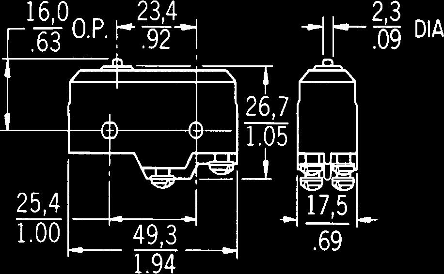

77 58 Honeywell Sensing and Control Forapplicationhelp:call Standard BZ/BA Series MOUNTING DIMENSIONS (For reference only) PIN PLUNGERS BZ/BM BA/BE PIN PLUNGERS SPECIAL CIRCUITRY Fig. 1 Fig. 2 Fig. 3 Fig. 4 Fig. 4-A Fig. 5 Fig. 6 Fig. 7 Fig. 8 Fig. 9 Fig. 10 Mounting holes accept pins or screws of.139 (3,53 mm) diameter.

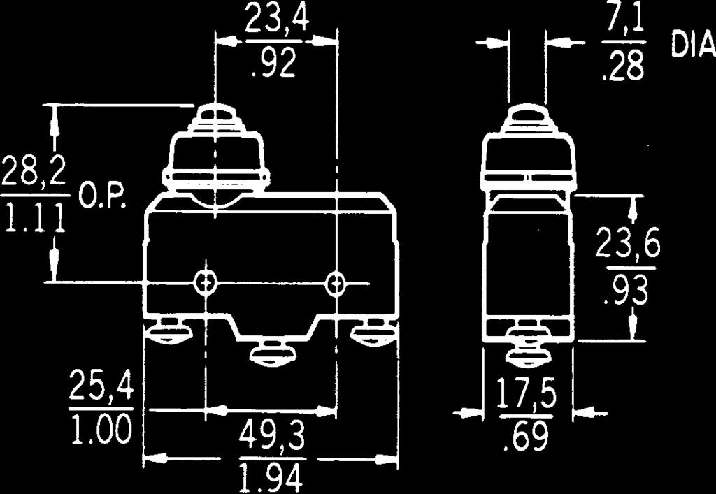


78 For application help: call Honeywell SensingandControl 59 Standard BZ/BA Series MOUNTING DIMENSIONS (For reference only) OVERTRAVEL PLUNGERS Fig. 11 Fig. 12 Fig. 13 Fig. 14 Fig. 15 Fig. 16 *Fig. 17 Standard * Threaded bushings are 15/32-32ns. *Fig. 18 *Fig. 19 *Fig. 20

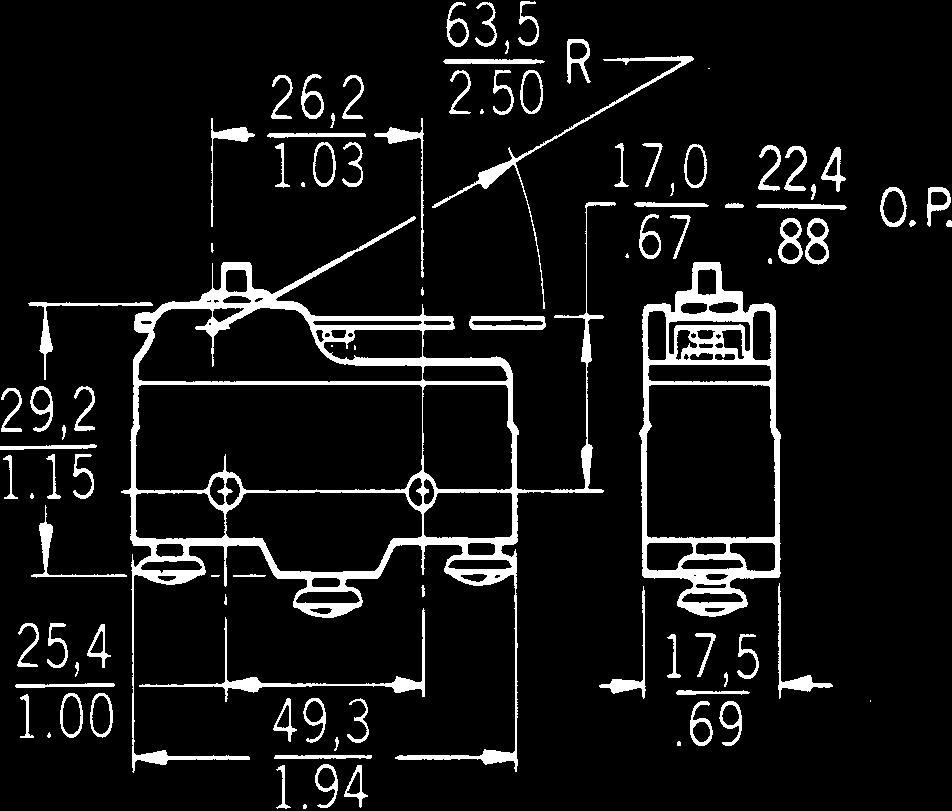

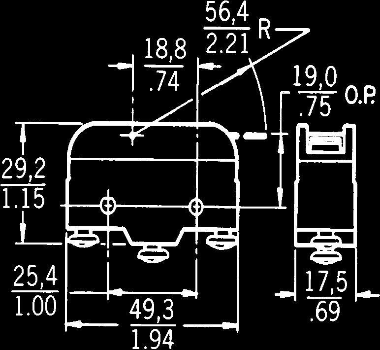

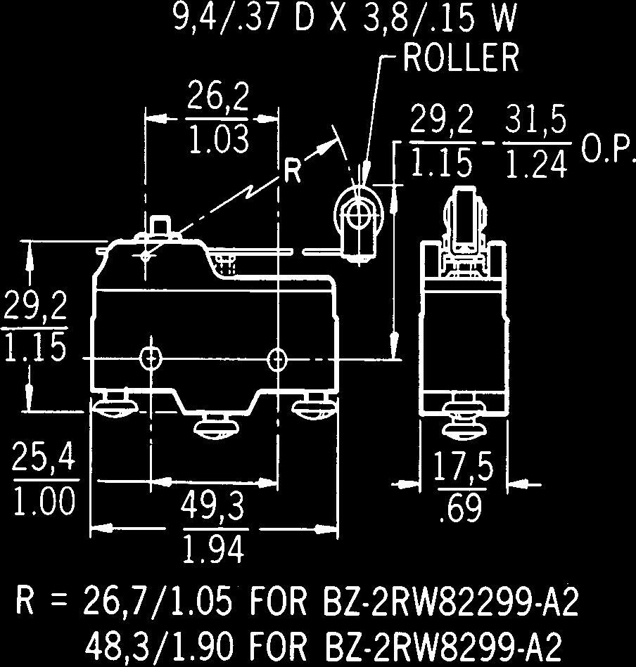


79 60 Honeywell Sensing and Control Forapplicationhelp:call Standard BZ/BA Series MOUNTING DIMENSIONS (For reference only) STRAIGHT LEVERS Fig. 21 Fig. 22 Fig. 23 Fig. 24 Fig. 25 Fig. 26 FLEXIBLE LEAF ACTUATOR Fig. 33 Fig. 34


80 For application help: call Honeywell SensingandControl 61 Standard BZ/BA Series MOUNTING DIMENSIONS ROLLER LEVERS FLEXIBLE ROLLER LEAF Fig. 27 Fig. 28 Fig. 29 Fig. 30 Fig. 31 Fig. 32 Mounting holes accept pins or screws of.139 (3,53 mm) diameter. Standard Fig. 35 Fig. 36


81 62 Honeywell MICRO SWITCH Sensing and Control For application help: call Auxiliary Actuators Standard Basic FEATURES Additional overtravel Quick, easy installation Corrosion resistance MIL-S-8805 listed units NOTE: Switches shown are not included with the actuator. All actuators are for use with pin plunger types only except catalog listing JR. GENERAL INFORMATION Auxiliary actuators adapt the plungertype standard basic switches to many application needs. Auxiliary actuators minimize the need for a large inventory of switch types. Actuators and switches are sold as separate items and must be ordered separately. Mounting hardware is furnished with the actuator. Fig. 1 Fig. 2 ORDER GUIDE Description Roller lever for S plunger type BZ and DT switches only. Permits cam operation. Adjustable roller lever. Tang on top of actuator can be bent to adjust O.P. and F.P. Catalog Listing Use Only With Characteristics: O.T. Overtravel; O.P. Operating Position; F.P. Free Position. O.T. min. mm inches O.P.* mm inches JR BZ ,45±3,18 DT ±.125 AD5721R (8805/59) AN ADA3721R ADD3721R BZ BM BA BE DT MT 11,1.437 approx. 9, approx. 9, approx. 31,75-41, , approx. 39, approx. F.P. max. mm inches 39,6-43, , , Straight plunger. Panel mount. MC2711 (8805/59) AN MCA2711 MCD2711 BZ BM BA BE DT MT 4, , , , , , , , , Fig. 3 Dimensions shown are for reference only. Except where stated * ±1,14 mm ±.045 in.


 BM.812 2.719 2.781 AN3167-1 MCA7711 BA 19,84 69,44 71,42 BE.781 2.734 2.")
82 For application help: call Honeywell nsingandcontrol 63 Auxiliary Actuators Standard Basics Fig. 4 ORDER GUIDE Use O.T. min. O.P.* F.P. max. Catalog Only mm mm mm Description Listing With Inches Inches Inches Sealed straight plunger. Panel mount. Elastomer seal boot keeps out liquid splash and dirt. Furnished unassembled. MC2711H BZ 4,78 28,98 29,4 BM MCA2711H BA 4,37 27,38±0,76 29,56 BE ± MCD2711H DT ,79 30,18 MT Fig. 5 Fig. 6 Roller plunger. Panel mount. Roller parallel to long axis of the switch. Cross roller plunger. Panel mount. Roller perpendicular to long axis of the switch. MD3211Q BZ 3,18 35,7 37,69 BM approx. MDA3711Q BA 3,18 36,12 37,69 BE MD3211Q DT 3,18 35,7 37,69 MT MD3211Q1 BZ 3,18 35,7 37,69 BM approx. MDA3711Q1 BA 3,18 36,12 37,69 BE MD3211Q1 DT 3,18 35,7 37,69 MT Standard Fig. 7 High overtravel plunger. Panel mount. MC7711 BZ 20,62 69,1 70,64 (8805/58) BM AN MCA7711 BA 19,84 69,44 71,42 BE MCD7711 DT 18,26 69,1 71,42 MT Except where stated* ±1,14 mm ±.045 in.


 centers.")

83 64 Honeywell Sensing and Control Forapplicationhelp:call Accessories Standard Basics DIE CAST ZINC ENCLOSURES Width of opening.74 (18,8 mm) FEATURES Protect switch from physical abuse Protect personnel from contact with exposed terminals Provide rugged mounting means 1/2-14NPT internal thread conduit hub 3PA1 *Width of base is inches (54 mm) and mounting hole centers are inches (41,3 mm) apart. PLASTIC TERMINAL ENCLOSURES 5PA1 ORDER GUIDE 3PA2* Catalog Listing Description 3PA1 Side mount enclosure Can be mounted from either side through.140 (3,55mm) dia. holes on 1 (25,4mm) centers. 3PA28 Side mount enclosure Can be mounted from either side through.140 (3,55mm) dia. holes on 1 (25,4mm) centers. 1/2-14 NPSM internal thread conduit hub. 3PA2 Flange mount enclosure Switch is first secured in enclosure; two (4,37mm) dia. holes in the flange accept #8 machine screws for mounting on (41,3mm) centers. 3PA6 Side mount enclosure For use with actuator Fig. 2 page 58. FEATURES Easy to use Screw and solder terminal versions Protect personnel from contact with exposed terminals 5PA1 WITH SWITCH ASSEMBLY ORDER GUIDE 5PA2 Catalog Listing 5PA1 5PA2 5PA3 Description For solder terminal switches For screw terminal switches For solder or screw terminal switches with auxiliary actuators assembled. Dimensions shown are for reference only. Switches are not included with enclosures.

 by loosening the locking screw, inserting a screwdriver in the adjusting slot, and twisting.")
84 For application help: call Honeywell SensingandControl 65 Accessories Standard Basics ADJUSTABLE MOUNTING BRACKETS FEATURES Sturdy plated steel construction Fast, easy screwdriver adjustment Can be used with all standard basic switches ORDER GUIDE GENERAL INFORMATION The operation point of a basic switch can be regulated up to.080 (2 mm) by loosening the locking screw, inserting a screwdriver in the adjusting slot, and twisting. 8MA1 WITH SWITCH ASSEMBLED MOUNTING DIMENSIONS CONVERSION MOUNTING BRACKET 17MA1-B 17MA1-B WITH SWITCH ASSEMBLED MOUNTING DIMENSIONS Catalog Listing 8MA1 8MA2 A Dimension for BZ Type 3,6/.14 BA Type 7,8/.31 FEATURES Converts standard basic switches from side to top mount Corrosion resistant Snaps into switch mounting holes without tools ORDER GUIDE Catalog Listing 17MA1-B Description Adjustable mounting bracket, adjustment slot on the left. Adjustable mounting bracket, adjustment slot on the right. Description Conversion mounting bracket. Standard Switches are not included with bracket.

 UL recognized, CSA certified AVAILABLE TERMINALS B6 6-32 UNC.188 (No. 5 pan head screws) A7 4-40 UNC.125 Screws with lockwashers.")
85 66 Honeywell Sensing and Control Forapplicationhelp:call Double-pole Double-throw DT Series ELECTRICAL RATING Circuitry Double-pole DOUBLE-POLE DOUBLE THROW Dim. Dwg. Fig. 1 Dim. Dwg. Fig. 9 J Electrical Data and UL Codes 10 amps, 125 or 250 vac; 0.3 amp, 125 vdc; 0.15 amp, 250 vdc. UL Code L59 ORDER GUIDE FEATURES Two independent single-pole doublethrow circuits on one housing Design permitting several wiring combinations Savings in space and weight Mounting interchangeability with type Z switches Temperature tolerance to +180 F (82 C) UL recognized, CSA certified AVAILABLE TERMINALS B UNC.188 (No. 5 pan head screws) A UNC.125 Screws with lockwashers. Fiberglas insulator isolates terminals and prevents accidental shorting. Characteristics: O.F. Operating Force; R.F. Release Force; P.T. Pretravel; O.T. Overtravel; D.T. Differential Travel; O.P. Operating Position. O.F. R.F. P.T. D.T. max. Electrical max. min. max. O.T. min. O.P.* Data and newtons newtons mm mm mm mm Catalog Listing Description UL Code ounces ounces inches inches inches inches DT-2R-A7 MS Pin plunger 10 Amps 3,34-5,56 0,56 1,91 0,13 1,02-1,52 15,6 J ±.015 DT-2RS1-A7 Straight plunger 10 Amps 3,34-5,56 0,28 1,91 0,51 1,02-1,52 28,2±0,38 J ±.015 Dim. Dwg. Fig. 3 DT-2RV3-A7 Straight lever Reversed lever position 10 Amps 1,11-1,95 0,14 6,86 0,25 2,92-4,83 18,3 J Dim. Dwg. Fig. 2 DT-2RV-A7 Straight lever 10 Amps 0,97-1,67 0,28 25,4 1,57 12,4-19,2 21,8 J Except where stated * ±0,76 mm ±.030 in.

86 For application help: call Honeywell SensingandControl 67 Double-pole Double-throw DT Series ORDER GUIDE Electrical O.F. max. R.F. min. P.T. max. O.T. min. D.T. max. O.P.* Data and newtons newtons mm mm mm mm Catalog Listing Recommended For UL Codes ounces ounces inches inches inches inches DT-2RV216-A7 Roller lever (centered steel roller) 10 Amps J 11,1 2.5 lbs. 1,11 4 1, , ,51-0, Dim. Dwg. Fig. 8 DT-2RV22-A inch (26,2mm) roller lever (steel roller) 10 Amps J 2,5-3, Dim. Dwg. Fig. 5 DT-2RV212-A7 Roller lever 10 Amps Reversed lever position J 2,5-4, ,83 3 0, , , , ,95-7, ,27-2, Dim. Dwg. Fig. 7 DT-2RV23-A7 Roller lever Reversed lever position 10 Amps J 1,53-2, , , , ,16-3, Dim. Dwg. Fig. 6 30,2±0, ± , , Standard DT-2RV2-A inch (48,3 mm) roller lever (steel roller) 10 Amps J 1,25-2, , , ,27-14, , Except where stated * ±0,76 mm ±.030 in. Dim. Dwg. Fig. 4 Auxiliary actuators see page


87 68 Honeywell Sensing and Control Forapplicationhelp:call Double-pole Double-throw DT Series MOUNTING DIMENSIONS (For reference only) PIN PLUNGER STRAIGHT LEVER Fig. 1 Fig. 2 STRAIGHT LEVER ROLLER LEVER Fig. 3 Fig. 4


 ROLLER LEVER ROLLER")

88 For application help: call Honeywell SensingandControl 69 Double-pole Double-throw DT Series MOUNTING DIMENSIONS (For reference only) ROLLER LEVER ROLLER LEVER Fig. 5 Fig. 6 ROLLER LEVER ROLLER LEVER Fig. 7 Fig. 8 STRAIGHT PLUNGER Standard Fig. 9
89 70 Honeywell Sensing and Control Forapplicationhelp:call Magnetic Blow-out MT Series FEATURES Arc resistant case Mechanical life of 100,000 operations 95% survival Temperature tolerance to +180 F (82 C) Mounting interchangeability with Z switches UL recognized GENERAL INFORMATION MT (single-pole ) magnetic blow-out switches are designed to switch high capacity (125 and 250 VDC) systems. An integral magnet around the contact gap protects the contacts by deflecting the arc. Vents between the cover and housing allow the hot gas to escape. These switches are designed for the control of DC motors, solenoids, etc. ELECTRICAL RATING Circuitry unless otherwise noted in order guide K Electrical Data and UL Codes Rating established with switch non-polarized 10 amps, 125 vac or vdc; 1/4 hp, 125 vac or vdc. UL Code L 168 Non-polarized: 10 amps res. or 1/4 hp, 125 vdc; 3 amps max. res. 250 vdc. Polarized*: 10 amps res. or 1/2 hp, 125 vdc; 3 amps max. res., 250 vdc. *To polarize, connect negative side of line to common terminal. To achieve the same effect, mount switch with brass screws, using a non-magnetic barrier (at least 1 4 thick) between the switch and mounting surface. ORDER GUIDE AVAILABLE TERMINALS Solder (No listing designation) A NC.218 Screws will accept up to #12 wire. Characteristics: O.F. Operating Force; R.F. Release Force; P.T. Pretravel; O.T. Overtravel; D.T. Differential Travel; O.P. Operating Position. Electrical O.F. R.F. min. P.T. max. O.T. min. D.T. max. O.P. Data and newtons newtons mm mm mm mm Catalog Listing Recommended For UL Codes ounces ounces inches inches inches inches Dim. Dwg. Fig. 1 MT-4R-A28 Pin plunger SPDT 10 Amps K 3,34-5, ,39 5 1, , ,1-0, ,9±0,38.625±.015
90 For application help: call Honeywell SensingandControl 71 Magnetic Blow-out MT Series ORDER GUIDE Electrical O.F. max. R.F. min. P.T. max. O.T. min. D.T. max. O.P.* Data and newtons newtons mm mm mm mm Catalog Listing Description UL Codes ounces ounces inches inches inches inches Dim. Dwg. Fig. 2 MT-4RV-A28 Straight lever 10 Amps K 0,56 2 0, , , , ,1.750 Dim. Dwg. Fig. 3 Dim. Dwg. Fig. 4 Dim. Dwg. Fig. 5 MT-4RV2-A28 MT-4RV22-A28 MT-4RL-A28 MT-4RL2-A inch (48,3mm) lever with hardened steel roller 1.03 inch (26,2mm) lever with hardened steel roller 1.95 inch (49,5mm) flexible leaf 1.82 inch (46,2mm) flexible leaf with hardened steel roller 10 Amps K 10 Amps K 10 Amps K 10 Amps K 0, , , , , ,28 1 8, , ,28 1 0,28 1 0, , , max. 1, max. 1, , , , , , Except where stated * ±0,76 mm ±.030 in. Standard
91 72 Honeywell Sensing and Control Forapplicationhelp:call Magnetic Blow-out MT Series MOUNTING DIMENSIONS (For reference only) PIN PLUNGER STRAIGHT LEVER Fig. 1 Fig. 2 ROLLER LEVER FLEXIBLE LEAF Fig. 3 Fig. 4 FLEXIBLE ROLLER LEAF Fig. 5 Mounting holes accept pins or screws of.139 (3,53 mm) diameter.

92 For application help: call Honeywell SensingandControl 73 Double-break 3MN Series ELECTRICAL RATING Circuitry Two-circuit double-break Dim. Dwg. Fig. 1 Electrical Data and UL Codes V Motor Control 15 amps, 120, 240, 480 or 600 vac; 1/2 hp, 120 vac; 1 hp, 240 vac; 0.8 amp, 115 vdc; 0.4 amp, 230 vdc. ORDER GUIDE MOUNTING DIMENSIONS (For reference only) FEATURES.080 inch minimum overtravel Power load switching capability up to 15 amperes Motor handling capacity of 1 horsepower at 240 vac. Long mechanical life of 10,000,000 cycles 95% survival Arc resistant plastic More space between terminals to reduce possibility of shorting #8 Terminal screws UL recognized, CSA certified GENERAL INFORMATION 3MN switches are for use with limit or control mechanisms on machine tools, presses or other industrial equipment. These switches provide easy gang mounting. The terminals of double-break switches must be wired to identical voltage sources and the same polarity. The loads should be on the same sides of the lines. Characteristics: O.F. Operating Force; R.F. Release Force; P.T. Pretravel; O.T. Overtravel; D.T. Differential Travel; O.P. Operating Position. R.F. P.T. O.T. Electrical O.F. min. max. min. D.T. O.P.* max. Catalog Data and newtons newtons mm mm mm mm Listing Description UL Codes ounces ounces inches inches inches inches 3MN1 For most 15 Amps 3,34-5,56 1,67 1,52 2,03 0,38-0,63 2,16 applications V MN6 Lower force 15 Amps 1,95-3,1 1,11 1,52 2,03 0,38-0,63 2,16 V * ±0,38 mm ±.015 in. Standard Fig. 1
93 74 Honeywell Sensing and Control Forapplicationhelp:call Tandem Switch Assemblies 6AS Series FEATURES Variety of actuators Choice of circuitries and electrical ratings Choice of terminations Field adjustable operating point on one or both basic switches GENERAL INFORMATION 6AS switches are two standard basic switches ganged together and actuated by a single actuator. Operating characteristics will depend on the type of individual switches and actuators. ELECTRICAL RATING Circuitry unless otherwise noted in order guide unless otherwise noted in order guide Dim. Dwg. Fig. 1 Electrical Data and UL Codes A 15 amps, 125, 250 or 480 vac; 1/8 hp, 125 vac; 1/4 hp, 250 vac; 1/2 amp, 125 vdc; 1/4 amp, 250 vdc. UL Code L96 G 20 amps, 125, 250 or 480 vac; 10 amps, 125 vac L (tungsten lamp load); 1 hp, 125 vac; 2 hp, 250 vac; 1/2 amp, 125 vdc; 1/4 amp, 250 vdc. UL Code L23 ORDER GUIDE Characteristics: O.F. Operating Force; R.F. Release Force; P.T. Pretravel; O.T. Overtravel; D.T. Differential Travel; O.P. Operating Position. Lever O.F. R.F. O.T. D.T. Length Electrical max. min. min. max. O.P.* Catalog mm Type Data and newtons newtons mm mm mm Listing Description inches Terminals UL Codes ounces ounces inches inches inches 6AS32 Centered lever. Adjustment over 58,72 15 Amps 2,22 0,14 0,51 2,77 18,29 both switches Solder A adj. 6AS54 Short lever. Adjustment over 20,47 15 Amps 3,34 0,83 0,25 3,96 18,24 switch D..806 Solder A max. 6AS25 Centered lever. Adjustment over 32,26 20 Amps 3,89 1,11 1,02 18,67 switch D A2 G Unless otherwise noted * ±0,76 mm ±.030 in.


94 For application help: call Honeywell SensingandControl 75 Tandem Switch Assemblies 6 AS Series ORDER GUIDE Dim. Dwg. Fig. 2 Dim. Dwg. Fig. 3 Lever O.F. R.F. O.T. D.T. Length Electrical max. min. min. max. O.P.* Catalog mm Type Data and newtons newtons mm mm mm Listing Description inches Terminals UL Codes ounces ounces inches inches inches 6AS13 Centered lever. Adjustment over switch D. 6AS18 Centered lever. Adjustment over both switches. 6AS36 Lever over switch C. Adjustment over switch D. 6AS35 Lever and adjustment over switch D. 6AS16 Centered lever. Adjustment over switch D. 6AS69 Centered lever. Adjustment over switch D. 6AS112 Centered lever. Adjustment over switch D. 6AS5 Centered leaf. No adjustment. Switches operate within.030 of each other. MOUNTING DIMENSIONS (For reference only) 30,56 15 Amps 2,22 0,14 0,51 2,77 29, Solder A ,56 15 Amps 2,22 0,14 0,51 2,77 29, Solder A adj. 30,56 15 Amps 2,22 0,14 0,51 2,77 29, A2 A ,56 15 Amps 2,22 0,14 0,51 2,77 29, A2 A ,56 20 Amps 3,89 1,11 1,02 3,96 30,96±1, A2 G ± ,25 25 Amps 30,96±1, T M 1.219± ,56 25 Amps 3,89 1,11 1,02 3,96 30,96±1, A2 H ± ,35 15 Amps 0,76-1, A2 A STRAIGHT LEVER ROLLER LEVER LEAF Unless otherwise noted * ±0,76 mm ±.030 in. Standard Fig. 1 Fig. 2 Fig. 3 Mounting holes accept pins or screws of.139 (3,53 mm) diameter.
SOLDER SHORT SOLDER SCREW
 32 Honeywell MICRO SWITCH Sensing and Control For application help: call 1-800-537-6945. CUT-A-WAY V3 MINIATURE BASIC SWITCH GENERAL INFORMATION V3 miniature basic switches feature high electrical capacity
Environment-Sealed Basic Switches
 HoneywellSensing and Control 1-800-537-6945 USA 1-815-235-6847International 1-416-293-8111Canada 13 Environment-Sealed Basic Switches GENERAL INFORMATION SE and XE switches are the smallest environment-sealed
Interactive Catalog Replaces Catalog Pages
 Interactive Catalog Replaces Catalog Pages Honeywell Sensing and Control has replaced the PDF product catalog with the new Interactive Catalog. The Interactive Catalog is a power search tool that makes
the Interactive Catalog
 Interactive Catalog Supplements Catalog PDFs If you need detailed product information, or help choosing the right product for your application, see our Interactive Catalog Use the Interactive Catalog to
the Interactive Catalog
 Interactive Catalog Supplements Catalog PDFs If you need detailed product information, or help choosing the right product for your application, see our Interactive Catalog Use the Interactive Catalog to
the Interactive Catalog
 Interactive Catalog Supplements Catalog PDFs If you need detailed product information, or help choosing the right product for your application, see our Interactive Catalog Use the Interactive Catalog to
Ordering Information. Snap Action Switch D2F. Subminiature Snap Action Switch D2F- Model Number Legend. Snap Action Switch D2F 31
 Snap Action Switch Subminiature Snap Action Switch Switches 3 A loads (general-purpose), 1 A loads (low force general-purpose) and 0.1 A loads(microvoltage/ microcurrent) Long life span assured by high-precision
the Interactive Catalog
 Interactive Catalog Supplements Catalog PDFs If you need detailed product information, or help choosing the right product for your application, see our Interactive Catalog Use the Interactive Catalog to
Safety Limit Switch
 Safety Limit Switch D4B-@N CSM_D4B-_N_DS_E_5_1 Snap-action contact with certified direct operation certification. Maintenance, seal, and resistance to shock increased and direct mechanism added. Three-conduit
D2SW-AQ. Sealed Subminiature Basic Switch Conforming to IP67 (Excluding the terminals on terminal models) Model Number Legend
 Model Number Legend") Sealed Subminiature Basic Switch Conforming to IP67 (Excluding the terminals on terminal ) Use of epoxy resin assures stable sealing, making this switch ideal for places subject to water spray or excessive
Sealed Subminiature Basic Switch Conforming to IP67 (Excluding the terminals on terminal ) Use of epoxy resin assures stable sealing, making this switch ideal for places subject to water spray or excessive
HL (AZH) LIMIT SWITCHES
 LIMIT SWITCHES") COMPACT SIZE LIMIT SWITCHES LIMIT SWITCHES U L PRODUCT TYPE 1. Limit Switches Actuator Type Push plunger Roller plunger Cross roller plunger Panel mount push plunger Panel mount roller plunger Panel mount
COMPACT SIZE LIMIT SWITCHES LIMIT SWITCHES U L PRODUCT TYPE 1. Limit Switches Actuator Type Push plunger Roller plunger Cross roller plunger Panel mount push plunger Panel mount roller plunger Panel mount
Subminiature Basic Switch
 Subminiature Basic Switch Subminiature Basic Switch Offers Long Life and High Reliability A design that combines simplicity and stability by the use of two split springs ensures a long durability of 30,000,000
High sensitivity. Low current load type. type. Short plunger ~ Fine plunger ~ ~ Lever ~ Roller lever ~ Short roller lever ~
 6 BZ, BA, BE Series Specifications Standard Basic Switches FEATURES These Switches are Used Extensively and Have Earned the High Respect of Our Customers. Standard basic switches (BZ, BA, BE Series) are
3SE03 North American Limit Switches
 General Information Features Modular plug-in Prewired receptacle with pin connector Prewired cable Features UL Listed, CSA Certified. UL File: E47512 All Metal Captive Screws. Keyed, Four-Directional Head.
HL (AZH) Limit Switches
 Limit Switches") COMPACT SIZE LIMIT SWITCHES HL (AZH) Limit Switches Wide selections of actuators, terminals and bodies to meet any application Excellent environmental resistance Die casting caseiec IP67 Plastic caseiec
COMPACT SIZE LIMIT SWITCHES HL (AZH) Limit Switches Wide selections of actuators, terminals and bodies to meet any application Excellent environmental resistance Die casting caseiec IP67 Plastic caseiec
TURQUOISE SWITCHES J TYPE (ABJ)
") HIGH ENVIRONMENTAL RESISTANCE TURQUOISE SWITCHES J TYPE (ABJ) Dust protected type Immersion protected type (wire leads bottom type) (Mounting hole 2.3mm.091inch type) (Mounting hole 2.3mm.091inch type)
HIGH ENVIRONMENTAL RESISTANCE TURQUOISE SWITCHES J TYPE (ABJ) Dust protected type Immersion protected type (wire leads bottom type) (Mounting hole 2.3mm.091inch type) (Mounting hole 2.3mm.091inch type)
D2SW-P. Sealed Subminiature Basic Switch. Ordering Information D2SW-P
 Sealed Subminiature Basic Switch Sealed Basic Switch with Simplified Construction, Mounting Compatible with SS and D2SW Series. Sealing by using rubber packing means the switch can be used in dust-proof
TURQUOISE SWITCHES J TYPE (ABJ)
") HIGH ENVIRONMENTAL RESISTANCE ABJ1,2,3,4,5 TURQUOISE SWITCHES J TYPE (ABJ) Dust protected type Immersion protected type (wire leads bottom type) (Mounting hole 2.3mm.091inch type) (Mounting hole 2.3mm.091inch
HIGH ENVIRONMENTAL RESISTANCE ABJ1,2,3,4,5 TURQUOISE SWITCHES J TYPE (ABJ) Dust protected type Immersion protected type (wire leads bottom type) (Mounting hole 2.3mm.091inch type) (Mounting hole 2.3mm.091inch
TF2 Series Miniature Snap-acting Switches
 Miniature Snapacting Switches Features/Benefits Broad range of operating forces Ratings up to 10 AMPS Wide variety of actuator styles Quick connect terminations Typical Applications Motor controls Thermostatics
Model Number Structure
 Small Sealed Switch D4E-@N Slim and Compact Switch with Better Seal and Ensuring Longer Service Life than D4E Flat springs with an improved lever ratio of the built-in switch ensure smooth snap action
VL Series. General Purpose Compact Limit Switches. Sensing and Control
 FEATURES Gold plated silver contacts Compact design for small mounting space. Special design for easy wiring with ample wiring space Two-circuit double-break Diecast base and plastic cover Standard mounting
onlinecomponents.com VL Series General Purpose Compact Limit Switches Sensing and Control
 FEATURES Gold plated silver contacts Compact design for small mounting space. Special design for easy wiring with ample wiring space Two-circuit double-break Diecast base and plastic cover Standard mounting
Limit Switches E47 Precision Switches
 1 PG.0C.0.T.E July 0 E47 Precision The Cost-Effective Solution for Highly Accurate Switching Applications Contents Overview...................... 1 Model Selection, Basic Switches................ 2 Model
Enclosed Switch. Ordering Information. Economical, High Utility Enclosed Switch. Model Number Legend D4MC- List of Models
 Enclosed Switch Economical, High Utility Enclosed Switch High precision and long life (10,000,000 mechanical operations) through employment of the moving spring used in OMRON Z Basic Switch. Sealed with
Switches. SERIES FEATURE ACTUATION MAX RATING SEAL RATING MOUNTING CIRCUITRY 115VAC, 28VDC)
") SWITCH SELECTION GUIDE Toggle Switches SERIES FEATURE ACTUATION MAX RATING SEAL RATING MOUNTING CIRCUITRY (Resistive @ 115VAC, 28VDC) T1 2 or 3 Position, Momentary, 8A MIL-PRF-83731 15/32" or 1/4" dia.
SWITCH SELECTION GUIDE Toggle Switches SERIES FEATURE ACTUATION MAX RATING SEAL RATING MOUNTING CIRCUITRY (Resistive @ 115VAC, 28VDC) T1 2 or 3 Position, Momentary, 8A MIL-PRF-83731 15/32" or 1/4" dia.
Ordering Information. General-purpose Basic Switch X. Direct Current Switch with Built-in Magnetic Blowout. Model Number Legend
 General-purpose Basic Switch X Direct Current Switch with Built-in Magnetic Blowout Incorporates a small permanent magnet in the contact mechanism to deflect the arc to effectively extinguish it. Ideal
KX Series Precision Sine Switches
 Precision Sine Switches FEATURES Hermetic seal provides exceptional operational freedom from environmental conditions Compactly designed to fit small, narrow spaces Available with either screw or solder
HL (AZH) Limit Switches
 Limit Switches") COMPACT SIZE LIMIT SWITCHES HL (AZH) Limit Switches Compact, high-performance limit switch with superior environmental resistance. Broad lineup covers from die casting cases to economical plastic cases.
COMPACT SIZE LIMIT SWITCHES HL (AZH) Limit Switches Compact, high-performance limit switch with superior environmental resistance. Broad lineup covers from die casting cases to economical plastic cases.
TURQUOISE SWITCHES ABJ TYPE
 HIGH ENVIRONMENTAL RESISTANCE ABJ1,2,3,4,5 TURQUOISE SWITCHES ABJ TYPE.5 12.8 Dust protected type Iersion protected type (wire leads bottom type) (Mounting hole 2.3 type) (Mounting hole 2.3 type) FEATURES
37T Series Moisture Resistant Temperature Controls
 37T Series Moisture Resistant Temperature Controls Moisture Resistant Temperature Control The 37T series of 3/4 (19mm) bimetal disc temperature controls from Therm-O-Disc offers proven reliability in a
l YZ-2R-A2 SPST (normally open) $8.05 l BZ-R-A2 Less differential travel l BZ-2R24-A2 Operating in temp. to
 $8.05 l BZ-R-A2 Less differential travel l BZ-2R24-A2 Operating in temp. to") Description l GSCA03S1 Safety hinge switch, 1-N.O. and 1-N.C., right $71.74 side hinge metal l GSCA03S3 Safety hinge switch, 1-N.O. and 1-N.C., left 71.74 side hinge metal l GSDA03S1 Safety hinge switch,
Description l GSCA03S1 Safety hinge switch, 1-N.O. and 1-N.C., right $71.74 side hinge metal l GSCA03S3 Safety hinge switch, 1-N.O. and 1-N.C., left 71.74 side hinge metal l GSDA03S1 Safety hinge switch,
Basic, Toggle, and Rocker Switches Product Range Guide
 Basic, Toggle, and Rocker Switches Product Range Guide For innovation that s well apart, there s only Honeywell With more than 50,000 products ranging from snap-action, limit, toggle, and pressure switches
SERIES 16, 18, 26 & 19N MICROSWITCH RANGES
 SERIES 16, 18, 26 & 19N MICROSWITCH RANGES SERIES 16, 26 & 18 - MICROSWITCH SERIES 16 & 26 FEATURES Form Z contacts to cover all switching requirements Snap action for positive switching Solder terminals
3SE03 North American Limit Switches
 General Information Features Modular plug-in Prewired receptacle with pin connector Prewired cable Features UL Listed, CSA Certified. UL File: E47512 All Metal Captive Screws. Keyed, Four-Directional Head.
Technical Guide for Basic Switches
 Terms for Basic Switches Technical Guide for Basic Switches General Terms (1) General Terms Basic Switch: A small-size switch with a very small contact gap and snap-action mechanism and with a contact
Limit Switch D4D- N. Small, Economical Switch Featuring a Positive Opening Mechanism and Conforming to the CE Mark
 Limit Switch Small, Economical Switch Featuring a Positive Opening Mechanism and Conforming to the CE Mark Features positive opening mechanism (NC contacts only) that opens contacts, thus preventing faulty
Snap-Action, Toggle, & Rocker Switches SENSING AND CONTROL. Product Range Guide
 Snap-Action, Toggle, & Rocker Switches SENSING AND CONTROL Product Range Guide 1 For innovation that s well apart, there s only Honeywell Sensing and Control. With more than 50,000 products ranging from
Distinctive Characteristics
 Distinctive Characteristics Full face or spot illumination with incandescent lamps or multi-element LEDs, with or without resistors. Short Body Pushbuttons Series YB Choice of super bright LEDs in white,
D2VW. Sealed Miniature Basic Switch. Ordering Information Model Number Legend D2VW- -
 Sealed Miniature Basic Switch D2VW Sealed Miniature Basic Switch Conforms to IP67 (Molded Lead Wire Type Only) Use of epoxy resin assures stable sealing, making this switch ideal for places subject to
Pressure Controller. Cataloge K Code Characteristics Index. K00-2 Pressure Controller Brief Introduction
 K Pressure Controller Cataloge Code Characteristics Index K00-2 Pressure Controller Brief Introduction KC32 Screw Tube Differential Pressure Controller K01 KY10 Bellows Type Differential Pressure Controller
Installation and Service Instructions for EX Series Explosion-proof Switches
 Installation and Service Instructions for EX Series Explosion-proof Switches ISSUE 4 50009662 WARNING PERSONAL INJURY DO NOT USE these products as safety or emergency stop devices or in any other application
AM5 (QV) SWITCHES AM5
 SWITCHES AM5") MINIATURE SWITHES WITH HIGH PREISION (QV) SWITHES 5.9 FEATURES High precision as a result of designing ideal spring by using computer analysis O.P. 4.7±0.4mm Reliable design with shock resistance min.
MINIATURE SWITHES WITH HIGH PREISION (QV) SWITHES 5.9 FEATURES High precision as a result of designing ideal spring by using computer analysis O.P. 4.7±0.4mm Reliable design with shock resistance min.
BZSeries. Basic Switches
 Basic Switches BZSeries These switches have been used extensively and have earned the high respect of our cusmers. Standard basic switches BZ Series are representative of Yamatake basic switches for their
D2SW. Sealed Subminiature Basic Switch. Ordering Information Model Number Legend D2SW-
 Sealed Subminiature Basic Switch Sealed Subminiature Basic Switch Conforming to IP67 (Molded Lead Wire Type Only) Use of epoxy resin assures stable sealing, making this switch ideal for places subject
Robust General-Purpose Limit Switch WL
 Robust General-Purpose Limit Switch WL Wide Selection of Two-Circuit Double-Break Limit Switches Rugged diecast housing High mechanical strength Oiltight, waterproof, dustproof construction Overtravel
BZSeries. Basic Switches
 Basic Switches BZSeries These switches have been used extensively and have earned the high respect of our cusmers. Standard basic switches BZ Series are representative of Yamatake basic switches for their
2NC (slow-action) Direct. Model. opening
 Direct. Model. opening") Small Safety Limit Switch CSM DS_E_3_1 Smallest Class of Safety Limit Switches in the World Note: Contact your sales representative for details on models with safety standard certification. The world's
Small Safety Limit Switch CSM DS_E_3_1 Smallest Class of Safety Limit Switches in the World Note: Contact your sales representative for details on models with safety standard certification. The world's
PCB Relay. Ordering Information. SPST-NO Type Breaks 10-A Loads; SPST-NO + SPST-NC Type Breaks 8-A Load G6C - - VDC
 PCB Relay SPST-NO Type Breaks 10-A Loads; SPST-NO + SPST-NC Type Breaks 8-A Load Compact: 20 15 10 mm (L W H). Low power consumption: 200 mw. Flux protection or fully sealed construction available. Unique
Lighted Pushbutton Switch
 Lighted Pushbutton Switch General Purpose and Micro-Voltage/Current Load Switch Requires only 22 mm mounting depth All LEDs, lamps, legends and pushbutton units replaceable without tools Oil-resistant
Safety Limit Switch
 Safety Limit Switch D4B-@N CSM_D4B-_N_DS_E_4_1 Snap-action contact with certified direct operation certification. Maintenance, seal, and resistance to shock increased and direct mechanism added. Three-conduit
D4B- N. Safety Interlock Switches. Safety Limit Switch. Specifications. Standards and EC Directives. Certified Standard Ratings D4BN
 Safety Interlock Switches D4B- N D4BN Safety Limit Switch Snap-action contact with certified direct operation. mechanism (NC contacts only) added to enable contacts when faults occur, such as fused contacts.
D2VW. Sealed Miniature Basic Switch Conforms to IP67 (Excluding the terminals on terminal models) Model Number Legend. Sealed Miniature Basic Switch
 Model Number Legend. Sealed Miniature Basic Switch") Sealed Miniature Basic Switch Conforms to IP67 (Excluding the terminals on terminal models) Use of epoxy resin assures stable sealing, making this switch ideal for places subject to water spray or excessive
Sealed Miniature Basic Switch Conforms to IP67 (Excluding the terminals on terminal models) Use of epoxy resin assures stable sealing, making this switch ideal for places subject to water spray or excessive
MINIATURE SWITCHES. Sensitive Snap-Action Pushbutton Switches Solder and P.C. Terminals (Momentary Action)
") Sensitive Snap-Action Pushbutton Switches Solder and P.C. Terminals (Momentary Action) MINIATURE SWITCHES PS SERIES 5 AMP. (S.P.) 1 AMP (D.P.) 0.4 VA DIRECT PANEL MOUNT Basic P/N Terminal Type Poles Cap
Sensitive Snap-Action Pushbutton Switches Solder and P.C. Terminals (Momentary Action) MINIATURE SWITCHES PS SERIES 5 AMP. (S.P.) 1 AMP (D.P.) 0.4 VA DIRECT PANEL MOUNT Basic P/N Terminal Type Poles Cap
A22NK. Key-type Selector Switches
 Key-type Selector Switches -mm dia. Key-type Selector Switches Control panel miniaturization through a more compact design and modified wiring direction. Addition of Push-In Plus terminal blocks for easy
Electropneumatic Timing Relays Series 7000 Industrial
 DESIGN FEATURES Available in On-Delay, True Off-Delay, and On/Off-Delay. Timing from 0.1 seconds to 60 minutes, fully calibrated in linear increments. Oversize time-calibrated adjustment knobs, serrated
2NC (slow-action) Direct. Model. opening
 Direct. Model. opening") Small Safety Limit Switch D4F CSM_D4F_DS_E_5_2 Smallest Class of Safety Limit Switches in the World Note: Contact your sales representative for details on models with safety standard certification. The
Small Safety Limit Switch D4F CSM_D4F_DS_E_5_2 Smallest Class of Safety Limit Switches in the World Note: Contact your sales representative for details on models with safety standard certification. The
Model Number Structure
 Power Relay G7J Electromechanical Relays A High-capacity, High-dielectric-strength, Multi-pole Relay Used Like a Contactor Miniature hinge for maximum switching power for motor loads as well as resistive
60T Series Snap-Action Temperature Controls
 60T Series Snap-Action Temperature Controls Snap-Action Temperature Control The 60T line of 3/4 (19mm) bimetal disc temperature controls from Therm-O-Disc offers proven reliability in a versatile, cost-effective
DIM. A (+ 0,05 0,51) .437 ±.020 (11,10 ± 0,51) DIM. F ±.015 (0,38) INTEGRAL ASSEMBLY NUT, DO NOT REMOVE
 .437 ±.020 (11,10 ± 0,51) DIM. F ±.015 (0,38) INTEGRAL ASSEMBLY NUT, DO NOT REMOVE") Multi-Deck SERIES,, and " Diameter, Amp, Standard, Military SR0 FEATURES Rugged Construction Insures Switch Operation for the Life of Your Equipment Many Circuitry Options MIL Qualified Versions MIL-S-/0
Multi-Deck SERIES,, and " Diameter, Amp, Standard, Military SR0 FEATURES Rugged Construction Insures Switch Operation for the Life of Your Equipment Many Circuitry Options MIL Qualified Versions MIL-S-/0
Multiple Lever Types. Proximity Limit Switch. Circuitry. The Proximity Limit Switch utilises magnetic switching to sense and trigger off ferrous
 Proximity Limit Switch The Proximity Limit Switch utilises magnetic switching to sense and trigger off ferrous metals. All components are sealed and protected within the rugged brass housing eliminating
Coil Data Nominal Current MA Nominal VA Sealed Single Pole Normally Open (SPNO) White Rodgers Q
 White Rodgers Q") 14/03/08 A136 Relay - General Purpose 90-293Q Enclosed fan relays used for switching single or two speed fan motors, solenoids, relays, resistive loads, heating and cooling applications and general purpose
14/03/08 A136 Relay - General Purpose 90-293Q Enclosed fan relays used for switching single or two speed fan motors, solenoids, relays, resistive loads, heating and cooling applications and general purpose
Cylinder Position Sensors
 TECHNOLOGY IN ACTION Stroke-to-GO LEVERLESS LIMIT SWITCH GO Switch Stroke-to-GO cylinder position sensors use three permanent magnets and push-pull plunger assembly to control a set of dry contacts. A
SERIES FEATURE ACTUATION MAX RATING SEAL RATING MOUNTING CIRCUITRY (Resistive)
") SWITCH SELECTION GUIDE Trim Switches SERIES FEATURE ACTUATION MAX RATING SEAL RATING MOUNTING CIRCUITRY (Resistive) MT T1 Quiet Operation, Momentary 10mA @ 5VDC IP64, IP68S 11/16 dia. Threaded SPST (x2)
SWITCH SELECTION GUIDE Trim Switches SERIES FEATURE ACTUATION MAX RATING SEAL RATING MOUNTING CIRCUITRY (Resistive) MT T1 Quiet Operation, Momentary 10mA @ 5VDC IP64, IP68S 11/16 dia. Threaded SPST (x2)
D4DS. Compact Interlock Safety Door Switch. Compact Safety Switch Saves Space and is Ideal for a Variety of Doors. Refer to Precautions on page 9.
 Compact Interlock Safety Door Switch Compact Safety Switch Saves Space and is Ideal for a Variety of Doors Positive opening mechanism and double insulation approved by TÜV and BIA. Five-direction Operation
SAFETY INTERLOCK SWITCH CONSTRUCTED WITH DUAL RESTORATION SPRINGS FEATURES
 SAFETY INTERLOCK SWITCH CONSTRUCTED WITH DUAL RESTORATION SPRINGS FEATURES mm inch or more is assured as insulation distance between contacts (Snap-in mounting and 3 Form A type) Durability of 100,000
Industrial Control Transformers
 6 Industrial Control Transformers Section 6 Industrial Control Transformers provide a low and safe control voltage for the operation of electromagnetic devices, such as motor starters, contactors, solenoids
Hinged Safety Door Switch
 Hinged Safety Door Switch Polymer housing, IP65, and slow-action contacts with positive opening. Two actuator types are available: Shaft Arm lever Arm lever type can be adjusted to allow a right (180 ),
Small Limit Switch D4V
 Small Limit Switch DV Compact Vertical Models Sized for Asian Standards Compact new design approximately / the size of OMRON vertical Limit Switches. Structure enables the terminal section to be fully
60T Series Snap-Action Temperature Controls
 Series SnapAction Temperature Controls SnapAction Temperature Control The line of 3/4 (19mm) bimetal disc temperature controls from ThermODisc offers proven reliability in a versatile, costeffective design.
SL (AZ3) Micro Limit Switches
 Micro Limit Switches") SUBMINIATURE SIZE LIMIT SWITCHES SL (AZ3) Micro Limit Switches Quickly upgraded to limit switches with lamps by mounting an LED lamp socket. Rubber cover type (roller ) Compliance with RoHS Directive FEATURES
SUBMINIATURE SIZE LIMIT SWITCHES SL (AZ3) Micro Limit Switches Quickly upgraded to limit switches with lamps by mounting an LED lamp socket. Rubber cover type (roller ) Compliance with RoHS Directive FEATURES
Mounting type Contact form PCB terminals Screw terminals Quick-connect terminals
 Power Relay A High-capacity, High-dielectric-strength, Multi-pole Relay Used Like a Contactor Miniature hinge for maximum switching power for motor loads as well as resistive and inductive loads. No contact
Distinctive Characteristics
 Distinctive Characteristics Carefully designed light diffusion and filtering system produce bright, full surface illumination with front panel relamping. Spot illumination available in single and bicolor
MICRO SWITCH Weather-Sealed, Explosion-Proof Switches. CX Series. Datasheet
 MICRO SWITCH Weather-Sealed, Explosion-Proof Switches CX Series Datasheet MICRO SWITCH CX Series Weather-Sealed, Explosion-Proof Switches MICRO SWITCH CX switches are built especially for outdoor use in
Power PCB Relay. Type Contact material Contact form Construction Part number General purpose AgCdO SPDT Semi-sealed G2R-1
 Power PCB Relay Creepage distance of 8.0 mm (0.31 in) min. between coil and contact Dual-winding latching type available Plug-in and quick-connect terminals available High sensitivity (360 mw) and high
SERIES SINGLE AND DOUBLE-POLE ROCKER SWITCHES
 TO 1 (4) A 50 V AC ROCKER SWITCHES PRODUCT FEATURES 100 million times proven switching principle High, fl exible design variety Excellent actuating characteristic Illuminated and non-illuminated variants
Compact plastic limit switches with positive opening mechanism
 Compact limit switches with positive opening mechanism LJK-N Series Positive opening mechanism Positive opening mechanism meets standards worldwide. A wide variety of actuators is available. The LJK-N
Load Resistive load (p.f. = 1) Inductive load (p.f. = 0.40, L/R = 7 ms) Rated load 5 A at 250 VAC, 30 VDC 2 A at 250 VAC, 30 VDC
 Inductive load (p.f. = 0.40, L/R = 7 ms) Rated load 5 A at 250 VAC, 30 VDC 2 A at 250 VAC, 30 VDC") Power PCB Relay G6D-ASI Reduced board space ideal for high-density mounting (45% smaller than the surface area of G6B). Slim package: measures 6.5 W x 17.5 L x 12.5 H mm Switches loads up to 5 A, 250 VAC/30
Power PCB Relay G6D-ASI Reduced board space ideal for high-density mounting (45% smaller than the surface area of G6B). Slim package: measures 6.5 W x 17.5 L x 12.5 H mm Switches loads up to 5 A, 250 VAC/30
PERFORMANCE SPECIFICATION SHEET SWITCHES, SENSITIVE, SPDT, UNSEALED
 INCH-POUND 14 June 2010 SUPERSEDING 22 May 2006 PERFORMANCE SPECIFICATION SHEET SWITCHES, SENSITIVE, SPDT, UNSEALED This specification is approved for use by all Departments and Agencies of the Department
Limit Switches. Reference Information. Proper Application of Limit Switches General Information. Definition of Limit Switch Terms.
 Reference Proper Application of General switches are used to convert a mechanical motion into an electrical control signal. The mechanical motion is usually in the form of a cam, a machine component or
Low-torque Basic Switch
 Low-torque Basic Switch Highly Reliable Rotary-action Switch for Low Torque Operation (0.5 m N m {5.1 gf cm}) 0.5-A rated model employs crossbar gold-alloy contacts for excellent contact reliability in
Life PERFORMANCE Catalog listing Standards Structure Electrical performance Mechanical performance Ambient operating conditions Recommende tightening
 SPATTER-GUARDED SWITCHES Model LS Effective countermeasures against the adhesion of spatter. UL/CSA/GB(CCC marking)-approved. (excluding some models) ORDER GUIDE Actuator Name Roller lever type Shape Max.
Safety-door Switch D4NS. Model Number Structure. Model Number Legend
 Safety-door Switch D4NS Multi-contact, Labor-saving, Environmentfriendly, Next-generation Safety-door Switch Lineup includes MBB models and three contact models with 2NC/1NC and 3NC contact forms in addition
VL (AZ8) Limit Switches
 Limit Switches") COMPACT SIZE LIMIT SWITCHES VL (AZ8) Limit Switches A compact and accurate vertical limit switch. Switches with indicator lamp available for convenient maintenance; either a neon AC powered lamp or an
COMPACT SIZE LIMIT SWITCHES VL (AZ8) Limit Switches A compact and accurate vertical limit switch. Switches with indicator lamp available for convenient maintenance; either a neon AC powered lamp or an
D4BS. Safety-door Switch. Model Number Structure. Switch D4BS - S Operation Key D4BS - K. Ordering Information
 Safety-door Switch Safety-door Switch s Special Operation Key Directly Pulls Apart the Contacts from Each Other and Contributes to the Safety of the Production Site Conforms to EN (TÜV) standards corresponding
D2HW. Sealed Ultra Subminiature Basic Switch. Ordering Information
 Sealed Ultra Subminiature Basic Switch Smallest sealed snap-action switch in the industry with a very long stroke for reliable ON/OFF action. The case dimensions are 78% of conventional models, contributing
MICRO SWITCH Heavy-Duty Limit Switch (Stainless Steel) HDLS LS2 Series
 HDLS LS2 Series") MICRO SWITCH Heavy-Duty Limit Switch (Stainless Steel) HDLS LS2 Series DESCRIPTION When the application requires an industrial grade limit switch where wet, dust, or corrosive environments may be present,
MICRO SWITCH Heavy-Duty Limit Switch (Stainless Steel) HDLS LS2 Series DESCRIPTION When the application requires an industrial grade limit switch where wet, dust, or corrosive environments may be present,
Basic Switches. BZ Series APPLICATIONS SELECTION GUIDE. High-quality switches with UL certification. *C-UL approval number: E96090.
 Basic Switches BZ Series These switches have been used extensively and have earned the high respect of our cusmers. Standard basic switches BZ Series are representative of Azbil basic switches for their
l Snap-Action Switches
 Connect - Contact - Control 2 Brochure l Snap-Action Switches Snap-action switches I Page 2 Page 3 I Snap-action switches Double Safety A sky diver's life depends on his equipment. In case of emergency
Miniature Basic Switches
 Miniature Basic Switches V-5000 Series Long-life, high-reliability models with a wide range of applications, from industrial products to household products. A wide range of models is available from high-capacity
PCB Relay. Contact form Terminal Single-side stable Single-winding latching
 PCB Relay Subminiature, Sensitive SPDT Signal Switching Relay High sensitivity: 98 mw pickup coil power. Impulse withstand voltage meets FCC Part 68 requirements. Plastic-sealed construction. Unique moving
Miniature Enclosed Limit Switch D4MC. Ordering Information. Economical, General-Purpose, Enclosed Switch. H High precision and long life (10,000,000
 R Miniature Enclosed Limit Switch Economical, General-Purpose, Enclosed Switch H High precision and long life (,000,000 mechanical operations) H Gasket diaphragm seal provides high environmental resistance
DL (AZD1) Mini Limit Switches
 Mini Limit Switches") COMPACT SIZE LIMIT SWITCES DL (1) Mini Limit Switches (with forced contact opening mechanism) An economic compact limit switch equipped with a forced contact opening mechanism and excellent environment
COMPACT SIZE LIMIT SWITCES DL (1) Mini Limit Switches (with forced contact opening mechanism) An economic compact limit switch equipped with a forced contact opening mechanism and excellent environment
Limit Switches with Positive Opening Mechanism
 Limit Switches with Positive Opening Mechanism LJA Series Positive opening mechanism Snap action limit switches with positive opening mechanism enables general industrial machines to comply with EC directives
Standard Plug-in/solder SPDT LY1 LY1F DPDT LY2 LY2F LY2Z LY2ZF 3PDT LY3 LY3F 4PDT LY4 LY4F PCB SPDT LY1-0 DPDT LY2-0 LY2Z-0
 General Purpose Relay LY Arc barrier equipped. High dielectric strength (2,000 VAC). Long dependable service life assured by Ag-Alloy contacts. Choose models with single or bifurcated contacts, LED indicator,
C&K 7000 Series Miniature Toggle Switches
 Miniature Switches eatures/benefits Multi-pole and multi-position Wide variety of actuator and termination options Epoxy sealed terminals prevent contamination during soldering Typical Applications Telecommunications
D4B-N. uce. Safety Limit Switch. Positive Action Limit Switches with Direct Drive Contacts for Critical Switching Applications
 Safety Limit Switch Positive Action Limit Switches with Direct Drive Contacts for Critical Switching Applications H Snap-action contact for accurate switching with safe operation via direct drive positive
Compact plastic limit switches with positive opening mechanism
 Compact limit switches with positive opening mechanism LJK-NSeries Positive opening mechanism Positive opening mechanism meets standards worldwide. A wide variety of actuators is available. The LJK-N conforms
Adjustable Dead Band Pressure Switches
 Form 281 The adjustable dead band pressure switch should be used when there is a requirement for an adjustable and wide dead band between the increasing and decreasing set points. Function Alarm: Hi Lo
8500 Series Subminiature Pushbutton Switches
 Subminiature Switches Features/Benefits Pre-travel or over-travel models available Ratings up to 3 AMPS Reliable contact design RoHS compliant Typical Applications Detection Telecommunications and networking
Distinctive Characteristics
 Distinctive Characteristics Full face or spot illumination with incandescent lamps or multi-element LEDs, with or without resistors. Choice of super bright LEDs in white, green, and blue as well as bright