Torq-Tronics Digital Torque Tester
|
|
|
- Hortense Malone
- 5 years ago
- Views:
Transcription
, 6 Nm (10392), 12 Nm (10393), 34 Nm (10394),")


1 Torq-Tronics Digital Torque Tester Owners Manual Revision A 5/2004 P/N: A For Models: 1 Nm (10391), 6 Nm (10392), 12 Nm (10393), 34 Nm (10394), 80 (10195), 150 (10196), 250 (10197), 600 (10198) Sturtevant RIchmont Division of Ryeson Corporation 555 Kimberly Drive Carol Stream, IL Phones: 800/ / Fax: 1-847/ CustomerService@srtorque.com Web: ISO Accredited Laboratory, ISO 9001 Registered Company
2
3 Table of Contents Section Page Safety Recommendations Meet Your Torq-Tronics Chapter 1 - Features Chapter 2 - Installation Chapter 3 - Testing Torque Wrenches and Torque Screwdrivers Chapter 4 - Power Tool Testing Overview Chapter 5 - Joint Simulators and Power Tool Testing Chapter 6 - Filters Chapter 7 - Testing Power Tools Chapter 8 - Calibration Chapter 11 - Frequently Asked Questions Specifications Page 1


4 Safety Recommendations For your safety and the safety of others, read and understand the safety recommendations before installing or operating the Torq-Tronics. Torq-Tronics Digital Torque Testers are designed and constructed to provide the user with a safe and reliable means of calibrating torque wrenches and power tools. Should a fault occur which impairs its function and/or compromises its safe use, immediately disconnect the unit from its power source and secure against unitended operation. Under no circumstances should repair be attempted by persons not qualified in the service of electronic instrumentation. When testing tool torque, always wear protective equipment: For additional information on eye and face protection, refer to Federal OSHA Regulations, 29CFR , Eye and Face Protection, and American National Standards Institute, ANSI Z87.1, Occupational and Educational Eye and Face Protection. Z87.1 is available from the American National Standards Institute, Inc., 11 West 42nd Street, New York, NY Hearing protection is recommended in high noise areas of 85 dba or greater. The operation of other tools and equipment in the area, reflective surfaces, process noises and resonant structures can substantially contribute to, and increase the noise level in the area. Excessive air pressure above 90 PSIG or worn motor components can also increase sound level emitted by the tool. Proper hearing conservation measures, including annual audiograms and training in the use and fit of hearing protection devices may be necessary. For additional information on hearing protection, refer to CFR , Occupational Noise Exposure, and American National Standards Institute, ANSI S12.6, Hearing Protectors. Page 2


5 Torq-Tronics Digital Torque Testers should be mounted and located such that inadvertent movement will not allow the unit to be dislodged, possibly causing personal injury or damage to the unit. Should the unit be dropped, it should be checked by someone qualified in the service of electronic instrumentation. WARNING: Shock Hazard. Disconnect power to the unit before attempting to service. Any internal adjustments should be carried out only by skilled persons who are aware of the hazards of dealing with live circuitry. The cabinet which houses the circuitry provides protection against dust and falling dirt. This unit should be used only indoors. Do not use in explosive atmospheres. WARNING: Shock Hazard. Damaged cords or plugs are dangerous, and should be repaired or replaced as necessary. CAUTION: Tripping Hazard. Electrical cords and tool cables must be organized and located in such a manner as to reduce the likelihood of the user others of tripping or becoming entangled in electrical cords and cabled used with this product. Route electrical cord so that it is not subject to chafing, crushing, or severing. Page 3


6 Page 4
 10 Fuse Page")
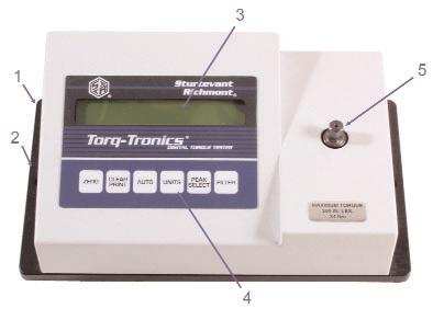
7 Meet Your Torq-Tronics 1 Back Plate 2 Mounting Hole (2 or 4 locations, depending on capacity) 3 Backlit LCD Display 4 Keys Zero Key Clear/Print Key Auto Key Units Key Peak Select Key Filter Key 5 Transducer Drive 6 Power Switch 7 Serial Port 8 Battery Compartment Cover 9 6 VDC Power Input (from supplied 120 VAC Adapter) 10 Fuse Page 5
8 Page 6 This page intentionally left blank.
9 Chapter 1 - Features Back Plate The Back Plate of your Torq-Tronics unit provides primary structural strength for it and a means by which the unit may be installed. Mounting Holes The Mounting Holes in the Back Plate provide a means of securing the unit in its' installed location. The holes are designed for use with 3/8" (or metric equivalent) bolts, and it is important to use bolts in all holes when installing your Torq-Tronics. Backlit LCD Display The 16-character Backlit LCD Display is your "information center" when operating your Torq-Tronics unit. It provides such information as software version, mode of operation, units of measure, direction of torque, automatic or manual printing/display clearing status, and warning of low battery power. Note: To conserve battery power, backlight operates only when charger is connected. Zero Key The Zero Key is used to return the unit to zero when changing torque test direction, or to zero when drift occurs. It is also used during the calibration process. It is important not to press the Zero key when torque is applied to the transducer. Clear/Print Key The Clear/Print key performs two functions. When pressed, it sends the torque measurement on the display to the serial port for communication to a computer or printer, then it clears the display for the next torque measurement. Auto Key The Auto key is a toggle switch which activates and deactivates the automatic status of the Clear/Print function. When the automatic print/automatic clear function is active, an "A" will appear behind the measurement units on the LCD display. When the automatic print/automatic clear function is deactivated, the displayed measurement must be printed and cleared manually by pressing the Print/Clear key, and no "A" will be displayed. Units Key The Units key is used to page through the measurement units the tester offers. The measurement units available on each tester are given in the Specifications chapter of this manual. Each time this key is pressed, it pages to the next measurement unit available in the series. Page 7
10 Peak Select Key The Peak Select key is used to select from among the four modes of operation: Track, Peak, Initial Peak, and Power Tool. When turned on, your Torq-Tronics always boots into Track mode. Each time this key is pressed, it pages to the next mode of operation. Track mode is used for calibration of the Torq-Tronics unit. When the tester is in Track mode, "Tk" will be displayed at the far right of the LCD. Peak mode is used for testing dial and beam torque wrenches. When the tester is in this mode, "PK" will be displayed at the far right side of the LCD. Initial Peak mode is used for testing clicker-type torque wrenches and torque screwdrivers. This mode captures the torque at which the torque stopped rising due to activation of the torque-limiting mechanism inside. When the tester is in this mode, "IP" will be displayed at the far right of the LCD. Power Tool mode is used for testing power tools. Torq-Tronics is suitable for testing continuous drive and non-continuous drive power tools of all types except impact wrenches. Impact wrenches may not be tested with it; attempting to test impact wrenches on your Torq-Tronics may damage the unit. In Power Tool mode filter selection is activated. Filter Key Filters are electronic devices which "clean up" the analog electrical signal coming from the torque transducer before the signal is measured and the measurement converted to torque. This filtering removes some of the top of the wave peak and the bottom of the wave trough in the signal from the transducer. There are five of these filters in the Torq-Tronics tester, and they are numbered "0" through "4". The lower the filter number, the more of the peak and valley is discarded before the signal is sent on for processing. The Filter Key pages through the four available filters in sequence. More about filters may be found in the chapter on filters and power tool testing. Transducer The transducer is the device which uses Hooke's Law and Ohm's Law to convert applied torque into an electrical signal. The front of the transducer has either a male hex drive (on units of 300 inch-pound capacity or less) or a female square drive (units of greater than 300 inch-pounds capacity). It is the transducer to which the torque tool is connected for testing. Battery Compartment Cover Retains the rechargeable AA nickel cadmium batteries. This cover should only be removed to replace batteries. Power Switch The power switch is used to turn on the tester for use or turn it off when testing has been completed. Page 8
11 Fuse Your Torq-Tronics tester has a ½ ampere Buss fuse in the fuse holder. Serial Port The serial port is a 9-pin port for serial communications with either a computer or serial printer. Data is sent to the port for transmission when the display is cleared, whether automatically or manually. 6 VDC Power Input The 6 VDC Power Input is provided for connection of the supplied 120 VAC to 6 VDC Adapter (240 VAC to 6 VDC in Europe) to the tester. Page 9
12 Page 10 This page intentionally left blank.
13 Chapter 2 - Installing Your Torq-Tronics Mounting - Location Selection There are several items that must be considered when selecting the location where your Torq-Tronics will be mounted. These are: Tool proximity. Do you want to test tools at or near their use location or do you want to bring the tools to a central location? Will you be using a computer and Torque Tool Manager (TTM) software with your Torq-Tronics? Solidity of mount. Your Torq-Tronics unit must be secured to a solid support to function properly. If the tester can move when a torque tool is tested, the motion will degrade the accuracy of the torque measurement, and over time the motion may damage the unit or the support the unit is attached to. The selected mounting location must also be equal to or larger than the base plate of the tester - full support of the base plate is required to achieve the required rigidity. See the Safety Recommendations at the front of this manual. Electricity source. Your Torq-Tronics requires a source of electricity to power the unit and recharge the batteries. The backlight of the LCD will only work when the unit is plugged into the proper power source. If you will be using a PC running TTM with your unit, electric power will be required for it as well. The installation must be close to an appropriate power source. See the Safety Recommendations at the front of this manual. Tester orientation. Units 34 Nm capacity and belows have been optimized for installation in the horizontal plane. Orienting the tester so the bottom of the faceplate faces the operator will make the tester easier to read and use. This orientation also minimizes the gravitational effect when the tool is engaged to the drive, enhancing accuracy. Higher capacity units are designed for either horizontal or vertical (as on a column or available stand) mounting. Power/Communications access. Your Torq-Tronics uses NiCd rechargeable batteries and a battery charger as electric power sources. The batteries will need to be replaced periodically. This requires removal and reinstallation of the battery plate cover on the side or rear of the Torq-Tronics unit. This is also the location of the charger receptacle, serial port, and power switch. It is important that sufficient clearance be maintained around the unit that access and workspace for battery replacement and power/communications connections be available. Note: Do not use other types of batteries. If power tools are to be tested, access to the air or electricity needed to drive them must be available, along with the space around the unit to maneuver them during testing. Connections to the power sources must be located such that the hoses or cables will not interfere with the tester operation. Page 11
14 Mounting to Selected Support Once the installation location has been determined, the actual installation process can begin. 1. Place your Torq-Tronics in the selected mounting location, supported as necessary to assure stability of the location and safety. 2. Mark the location of the mounting holes on the surface to which the tester is to be mounted. 3. Remove the Torq-Tronics from the installation location, and drill or drill and tap mounting holes. 4. Your Torq-Tronics may be mounted with bolts and nuts or with bolts into a drilled and tapped hole. Regardless of method, the Torq-Tronics is designed to be mounted with 3/8" (or metric equivalent) diameter bolts. Bolts should be at least SAE Grade 5, with SAE Grade 8 preferred. Drill, and if necessary, tap the holes. 5. Place the Torq-Tronics over the holes and install the bolts, and if necessary, nuts. Check to insure that the tester does not move after the fasteners have been installed. Electrical Connection 1. The first step in providing power is installation of the four (4) AA NiCd batteries. a. Remove the two Phillips head screws holding the battery cover in place on the Torq-Tronics unit. Use a #1 Phillips screwdriver. b. Gently remove the battery cover and attached battery pack from the Torq-Tronics unit. Do not move the cover and battery pack any further from the unit than is necessary to install the batteries! The wires from the battery pack to the internal electronics are small and soldered inside. Placing excessive tension on them will break the wires and necessitate returning the unit for repair! c. Open the package containing the supplied batteries. d. Following the battery orientation shown inside the battery pack, install all four batteries into it. It is important that proper battery orientation be maintained! e. Gently push the wires connecting the battery pack to the internal electronics into the unit while replacing the battery cover back in its' original position. f. Reinstall the two Phillips head screws used to retain the battery cover in place. The screws should only be tightened snug. 2. The second step in providing power to your Torq-Tronics is connection to the AC power source. a. Unwrap the AC to DC Adapter supplied with your Torq-Tronics. b. Plug the charger pin into the 6 VDC power input on the rear of the unit. c. Plug the other end of the charger into a properly wired 120 VAC (240 VAC in Europe) outlet. Page 12
15 Computer Communications (Optional) If you will be using your Torq-Tronics with a computer and TTM software or a serial printer, this is the time to establish communications. 1. Gently insert the male end of your 9-pin serial cable into the serial port on your Torq- Tronics unit. 2. Thread the externally-threaded fasteners on either side of the cable terminal into the internally-threaded securing nuts on either side of the serial port. Tighten fasteners just enough to secure cable terminus in position. 3. Connect the other end of the serial cable to the serial port on your computer or serial printer. 4. Serial communications parameters are: 4800 baud, No parity, 8-bit, 1 stop bit. Test Installation The last step in the installation process is checking to insure the unit works as installed. 1. Testing Electrical Power Supply a. Move the power switch to the on position. If the batteries are properly installed and AC power is connected, the backlit LCD display will come on, a series of messages will be displayed, and the unit will finish in Track mode at zero torque value in English units of measurement. If the backlights on the LCD are not lit, it means the unit is not properly connected to an AC power source. Check power to the AC outlet, that the charger is firmly plugged into the outlet, and that the charger pin is fully inserted into its' receptacle in the Torq-Tronics unit. b. Unplug the charger from the 120VAC (240 VAC in Europe) outlet. If the backlight on the LCD goes out but the characters remain displayed, the batteries have been properly installed. If the backlight goes out and the characters do not remain displayed, the batteries have either not been installed or have been improperly installed. To correct this, move the power switch to the off position, remove the battery pack cover, remove and properly reinstall the batteries, then reinstall the battery pack. Move the power switch to the on position and the characters will be displayed. c. Move the power switch to the off position and reconnect the charger to the 120 VAC (240 VAC in Europe) power outlet. 2. Testing communications (Optional) a. Computer Communications Test i. Activate terminal software. ii. Move the power switch on the Torq-Tronics to the on position. iii. The message "Sturtevant Richmont" then "System 7 Ver 2.0" then "TORQTRONICS [Model]" will appear in the terminal software window if the Torq-Tronics is properly connected and the proper serial port is selected and properly configured. If these letters do not appear, check for proper cable connection, proper port selection, and proper port configuration. Serial communications specifications may be found in the Specifications section of this manual. Page 13
16 Page 14 b. Serial Printer Test i. Move the power switch on the Torq-Tronics unit to the on position. ii. Turn on the printer. iii. The message "Sturtevant Richmont" then "System 7 Ver 2.0" then "TORQTRONICS [Model]" will print if the printer is properly connected and the power is on. If this does not occur, check printer power, printer settings, and serial cable connections.
17 Chapter 3 - Testing Torque Wrenches & Manual Torque Screwdrivers This section covers the testing of clicker-type torque wrenches and manual torque screwdrivers using your Torq-Tronics. These tool types have a specified accuracy of ± 4% to ± 6% Indicated Value (I.V.) or less, and are suitable for testing on the Torq-Tronics, which has an accuracy of ± 1% I.V. Tools of accuracy tighter than ± 4% I.V. can be tested, but not certified with this tester. This includes most dial- and beam-type torque wrenches. If you have a need to certify such tools, contact Sturtevant Richmont for assistance in selecting an appropriate torque measurement system. This section assumes yourtorq-tronics has been properly installed, and that any communications connections have been made. If these steps have not been performed, please perform them according to the instructions in the preceding chapter. A clicker-type torque wrench will be used as the first example in this chapter. The procedure for testing a torque screwdriver is the same as that used for the clicker-type torque wrench. Starting the Torq-Tronics 1. Move the power switch to the ON position. 2. Allow the Torq-Tronics to boot up. During this process, two messages will be displayed on the LCD. a. "System 7 Ver 2.0" b. "TORQTRONICS [Model #]" 3. After these two messages have been displayed and cleared, the tester will display its operating status on the LCD. This will consist of: a. A plus (+) or minus (-) sign in front of b. a torque value at or near zero, followed by c. the units of measure currently in use. d. There will then be one or two blanks, followed by e. "TK" to indicate the tester is in Track mode. 4. If the displayed torque value is not zero, press the Zero key to return the tester to zero value. 5. Press the Peak Select key twice to page from Track mode to Initial Peak mode. The last two characters on the display will change to "IP" when the tester has entered this mode. 6. If you wish the test results to automatically print and clear from the LCD within a few seconds of test completion, press the Auto key once. An "A" will be displayed immediately behind the units of measure. If you wish the torque measurement to be displayed until you wish it cleared, you need do nothing. Clearing each measurement from the display will require pressing the Clear/Print key after each display when in manual mode. Page 15
18 Page 16 Preparing the Torque Wrench Check that the torque wrench to be tested is of equal or lesser torque capacity than the tester. Under no circumstances should the Torq-Tronics be used beyond its' rated capacity! Adjust the torque wrench to the desired torque level for testing. If your Torq-Tronics has a male hex drive; put a socket of the same size on the front of the torque wrench, so the transducer drive can be engaged by the tool. If an interchangeable head torque wrench is being tested, use a head with a hex opening equal to the size of the hex drive. If your tester has a square drive, engage the tool directly to the tester. Use a square drive adapter if needed. Testing the torque wrench. Grasp the torque wrench at its' load point, and apply slowly increasing force steadily until it clicks. Stop applying force immediately, and allow the torque wrench to reset. The measurement will be displayed on the LCD. Testing a Dial or Beam Torque Wrench 1. Move the power switch to the ON position. 2. Allow the Torq-Tronics to boot up. During this process, two messages will be displayed on the LCD. a. "System 7 Ver 2.0" b. "TORQTRONICS [Model #]" 3. After these two messages have been displayed and cleared, the tester will display its operating status on the LCD. This will consist of: a. A plus (+) or minus (-) sign in front of b. a torque value at or near zero, followed by c. the units of measure currently in use. d. There will then be one or two blanks, followed by e. "TK" to indicate the tester is in Track mode. 4. If the displayed torque value is not zero, press the Zero key to return the tester to zero value. 5. Press the Peak Select key twice to page from Track mode to Peak mode. The last two characters on the display will change to "Pk" when the tester has entered this mode. 6. If you wish the test results to automatically print and clear from the LCD within a few seconds of test completion, press the Auto key once. An "A" will be displayed immediately behind the units of measure. If you wish the torque measurement to be displayed until you wish it cleared, you need do nothing. Clearing each measurement from the display will require pressing the Clear/Print key after each display when in manual mode. Testing the torque wrench. Grasp the torque wrench at its' load point, and apply slowly increasing force steadily until it reaches the test point. Stop applying force immediately, and allow the torque wrench to return to zero. The measurement will be displayed on the LCD. Compare tool memory needle to tester reading.
19 Chapter 4 - Power Tool Testing Overview Types of Power Tools Power tool types may be broken down into two basic categories: continuous drive and noncontinuous drive. Continuous drive tools are those that drive until a selected torque is reached. Clutch and stall tools are examples of continuous drive tools. Non-continuous drive tools are those where the power is not continuously applied. Examples of this type are impact wrenches and pulse tools. Of the non-continuous drive tools, only pulse tools may be tested on your Torq-Tronics. Impact tools are not to be tested on the Torq-Tronics family of testers. Doing so will invalidate the tester warranty and probably damage the tester. Automatic Shutoff Tools (Stall, Clutch, Continuous Drive) All automatic shutoff tools use the joint for feedback to the shutoff mechanism. This means that the joint is part of the control loop which determines the shutoff point, and the final torque, achieved on the fastener by the tool. The tool affects the joint by tightening the fastener, which affects the tool by resisting further rotation, which affects the shutoff mechanism. This loop starts when the tool is activated while engaged with the fastener, and ends shortly after the shutoff mechanism activates. The tool and joint do not stop interacting the instant the tool shuts off. All of the rotating components in the tool have momentum from the rotation. Once the power shuts off, these components (motor shaft, drivetrain components, chuck, and bit or socket) continue to interact with the fastener until all momentum is dissipated. This is one of the primary reasons that filters and joint simulators are used. Non-Shutoff Power Tools (Pulse, Discontinuous Drive) Non-shutoff or manual power tools continue to apply torque as long as power is present and the tool is activated. The torque actually transmitted to the fastener will not perpetually increase, even when the tool is activated for a long period of time. Once the fastener torque has increased to the maximum output of the tool, either the tool will stall, the clutch will slip, or the applied torque will simply stop moving the fastener because the torque is less than that already on it. Pulse Tools - Special Considerations A pulse tool is essentially an impact tool with a buffer between the hammer and the anvil. Due to the impacting pulses on the joint, these tools are typically joint sensitive. The actual torque transmitted to the joint is a function of the peak output of the tool and the joint rate Page 17
20 (hardness or softness). Within limits, the harder the joint, the higher will be the torque on the fastener at the same torque setting on the tool. Pulse tool manufacturers use varying design approaches. Pulse tools of Japanese manufacture tend to differ in approach from those of American or European manufacture. In the chapter on Filters a general guide is given to filter selection for testing the various types of tools, including pulse tools. Page 18
21 Chapter 5 - Joint Simulators and Power Tool Testing Joint Hardness Joint hardness is the rate at which a joint develops clamping force as torque is applied to the fastener. Any given joint may be "hard", "soft", or somewhere in between. Note: Joint hardness is classified in accordance with the ISO 5393 standard. A "hard" joint is one which requires very little fastener rotation to develop the joint preload (clamping force) desired for the assembly. Stated another way, there are very few degrees of fastener rotation, and very little time, from the moment the fastener develops a small percentage (10%) of the fastener preload desired to the moment the fastener develops 100% of the desired preload. TORQUE This is depicted in the first diagram. In this diagram, the horizontal axis is time or rotation angle, and the vertical axis is the torque which results in clamping force. The very rapid rise in torque and clamping force over very little time is what defines a hard joint. TIME/ANGLE TORQUE The next diagram is of a medium joint. Notice that the rise in torque and clamping force takes more time - fastener rotation - than it did in a hard joint. The angle of rotation is between 30º and 270º. TIME/ANGLE Page 19
22 TORQUE The third diagram is of a soft joint. Notice the slow rise in torque; it takes more time - and fastener rotation - to reach the same installation torque. The angle of fastener rotation is greater than 270º. TIME/ANGLE Joint Hardness and Power Tool Calibration Almost all continuous drive power tools rely on the reaction of the joint to determine when to shut off. The tool affects the joint by tightening the fastener. The joint affects the tool by varying torque feedback. The feedback is as much a part of the torque control as is the clutch or valve that triggers the tool shutoff. If a power tool is tested or calibrated on a joint that is feeding back information significantly different from the feedback the power tool will receive when used on the assembly line, the results may be markedly different from each other. The tester will show a torque output of one level, but a test of the fastener torque on the assembly after the tool is used will show a different torque. It is for this reason that rundown fixtures were developed, and are used in most power tool calibrations. Rundown Fixtures A rundown fixture is a device intended for use in power tool torque testing on torque transducers. It is designed to emulate the reaction of a wide range of joint hardnesses. By doing this, it permits the user to obtain test results that are more predictive of actual tool performance on the line. Rundown fixtures typically contain: A means of being attached to the torque transducer drive. A set of Belleville washers (or a spring) which can be configured to emulate the joint response. Only joint simulators with Belleville washers are adjustable for joint rate simulation. Joint simulators with springs have a joint rate fixed by the spring rate, and can only be adjusted by spring replacement. A means of compressing the washers while transmitting the applied torque to the torque transducer. If you encounter a problem with testing continuous drive power tools and changing the filter selection does not solve it, installing a rundown fixture to the tester transducer drive and configuring it to match the joint rate is probably needed. Page 20
23 Chapter 6 - Filters Purpose The electronic filters in the Torq-Tronics Digital Torque Testers perform two key functions: preventing electronic noise from causing inaccurate torque readings, and assisting in the discrimination of the true applied torque signal from the extraneous signals generated by power tool mechanisms. The first of these filtering functions is straightforward. These testers are often used in electronically "noisy" environments. Lights, electric motors, and power lines are just some of the sources of electronic noise present in factories and laboratories. The wires in the Torq- Tronics can pick up this noise, and send it to the torque analysis circuitry. Part of the purpose of the filters is to eliminate this problem. The second purpose of the filters is to enable the user to separate the mechanical actions of the power tool which perform the work of applying torque from those actions which result in signals but which do not actually apply torque to the fastener. Filtering Concept In Chapter 5, concept drawings were used to explain the relationship of time and degrees of rotation to the applied torque and the clamping force it generates. For the sake of clarity, these drawings were simplified to straight lines. The next drawing is more typical of the actual performance of a power tool in use, as shown on an oscilloscope. In this drawing, time is the horizontal axis, and voltage is the vertical axis. The horizontal line is the starting voltage from which torque is measured. The horizontal line = no torque. The erratic line is the voltage coming from torque transducer, unfiltered In this drawing, the power tool has been used to run down a single fastener. The tool shut off when it reached the shutoff torque. The slope of the line (#1) during the rundown of the fastener is not a smooth line; the rundown is not as smooth as it appears to the human eye. The acceleration and deceleration of the torque application rate is the result of the inevitable imperfections in the fasteners, the power tool, the joint components, and how they interact during the rundown phase of the power tool use. Page 21
24 The tool actually shut off at the peak labeled point #2. Once the power driving the bit was shut off, regardless of the means, the bit rebounded off the drive of the fastener, and created a backlash through the drive mechanism of the tool. This created torque in the opposite direction, as displayed by the line running from point #2 to point #3. The components of the tool drive continued to rebound off each other, as shown in points #4, #5, and the rest of the line to the right of them, until it stabilized at zero. The graph discloses a number of peaks during fastener rundown, as well as those occurring at and after tool shutoff. This type of action - not identical, but similar - occurs with all non-impacting power tool types on all joints. There are many variables involved: the power tool type, the individual tool, the fasteners, the joint rate, the tool power supply, rundown speed, the tool's shutoff mechanism, and the broad variety of the interactions between them. These sources of mechanical "noise" create the electronic noise that must be eliminated to determine what will be the actual applied torque on the fastener. It is the filter, augmenting the joint rate emulation of the rundown fixture, which permits effective off-line calibration with confidence the results on the tester will correlate with the results in the assembly process. There are five (5) filters provided on each Torq-Tronics. The filters are numbered 0, 1, 2, 3, and 4. Each filter provides a different amount of noise reduction, with Filter 0 having the most filtering and Filter 4 the least. Since there are only five filters, and there are an extraordinary variety of joints and power tools on which the tester might be used (and more power tools and applications coming out every year), learning to balance the joint simulator and the filters is a key to assuring a successful power tool testing program. The following list is provided as a guide to filter selection in power tool testing. It is a guide intended for use as a start point. The actual filter that provides the most accurate test results will vary by power tool type, configuration, and joint, and will have to be determined by experimentation. Filter Hz Suggested Application (Start Point Only) Clutch-type tools having dramatic clutch bounce ISO 5393, clutch- or stall--type tools - recommended filter Pulse tools of Japanese design and manufacture Pulse tools of American/European design and manufacture Pulse tools of American/European design and manufacture Filter values above are +/- 5%. Experiment to find the filter that produces results that correlate with post-assembly joint audit results. Usually one of the filters will work. If not, a rundown fixture is likely needed. Page 22
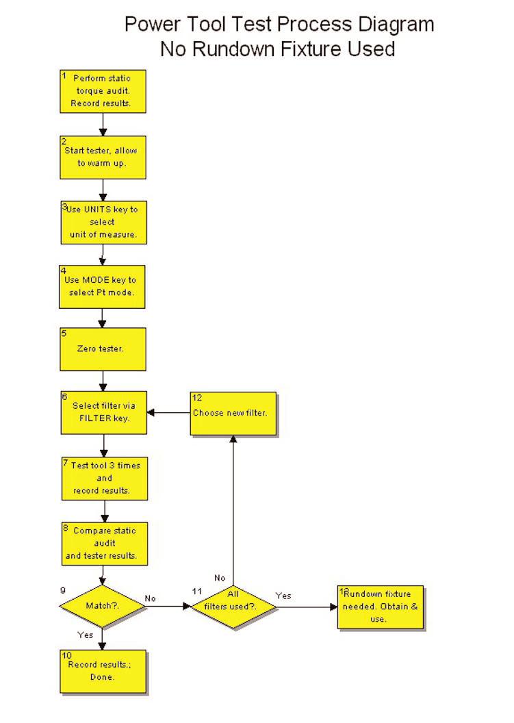
25 Chapter 7 - Testing Power Tools Power tools of 10 inch-pound capacity or less should not be tested using a rundown fixure. Tools ranging upwards from there may require the use of a rundown fixture as well as the filters on the Torq-Tronics. This procedure assumes the tester has been installed per the instructions in Chapter 2 of this manual. The procedure given below assumes exact measurement of the individual joint/tool combination is desired. This procedure may be modified as needed for a correlative approach. Procedure 1) Measure Joint a) Perform a static audit of the joint the tool is used on. b) Record the data. It will be used as comparison data for the results obtained from the tester. 2) Start the Torq-Tronics tester. a) Use the Power Switch to turn on the tester, and allow it to boot up. b) Allow the tester to warm up for 10 minutes. c) If a rundown fixture will be used, configure it for the test and install it on the transducer hex drive. 3) Use the Units key to select the units of measure to be used. 4) Use the Mode key to select the Power Tool mode (Pt). The tester will automatically select Filter 0 as the default. 5) Use the Filter key to select the filter to be used during the test. If the correct filter is not known, use the table on the preceeding page as a guide to a good start point. To change the filter, simply press the filter key and page through them until the desired filter is displayed. Stop pressing the key and the tester will revert to the Power Tool test mode after a couple of seconds. 6) Press the Zero key to assure the tester is zeroed prior to the test. 7) Test the tool. a) Test power tool; directly if no rundown fixture is used, or by running down the fastener if one is used. b) Record the torque displayed on the LCD of the tester. 1) Loosen the fastener back to its' original position if a rundown fixture is used. d) Press the Clear/Print key to clear the display. e) Repeat the above four steps two more times. Page 23
26 8) Compare the results to the actual applied torque obtained from the joint. a) If the results agree with the actual output of the tool on the joint, record the information on the rundown fixture configuration and filter used for this test for future use with this tool. Testing complete. b) If the results do not agree with the actual output of the tool on the joint, and all filters have not yet been tried, another filter may be better to use with this combination of tool and joint. Go to step 9. c) If the results do not agree with the actual output of the tool on the joint, and all five filters have been tried, then a rundown fixture (if one was not used) or an adjustment to the rundown fixture (if one was used) will be needed. i) Use the Power Switch to turn off the tester. ii) Remove the rundown fixture from the tester. iii) Adjust the rundown fixture to emulate a harder or softer joint. iv) Return to Step 3 of this procedure. 9) If the test results do not match the tool output, and all four filters have not yet been tried, it may be that the rundown fixture is correct but a different filter may be needed. a) Press the Filter button on the Torq-Tronics tester to change to the next filter. b) Repeat steps 6, 7, and 8 of this procedure. Page 24
27 Page 25
28 Page 26 This page intentionally left blank.
29 Chapter 8 - Calibration The calibration procedure for each model differs primarily in the arm and weight combination required to reach the calibration points for the model's torque capacity. Each procedure requires the use of: * A computer equipped with a serial port and terminal software. * A serial cable. * Calibration weights, drive squares, arms, and platforms for the model to be tested. * Refer to the "Calibration Table - Torq-Tronics Models" at the end of this chapter. Calibration Procedure 1) Turn on the Torq-Tronics unit. Allow it to warm up for one (1) hour in Track mode. 2) Connect Torq-Tronics unit to computer via serial cable. 3) Start terminal software. 4) For a summary of the calibration commands, type :CM into the terminal software, then press the "Enter" key. 5) Press the ZERO key on the Torq-Tronics unit, then type :CM2 into the terminal software and press the Enter key. Observe acknowledgement of calibration zero. 6) Obtain the proper calibration arm. The correct arm can be found in the "Calibration Table -Torq-Tronics Models" at the end of this chapter. 7) Make certain the calibration arm is properly counterbalanced. 8) Attach the drive square of the calibration arm to the drive of the tester in the clockwise direction, and press the Zero key. 9) Hang the weight platform (hook) and the full-scale weights (100%) (found in the "Calibration Table - Torq-Tronics Models") on the calibration arm - gently, and imparting as little motion to the weights as possible. Wait until the weights have completely stopped moving, then remove the full-scale load. 10) Wait one minute, then press the ZERO key on the tester. 11) Repeat steps 9 and 10 two more times, then proceed to step ) Hang the 1st calibration point (10%) weights, as found in the "Calibration Table - Torq-Tronics Models", on the arm, gently. Wait for the arm to completely stop moving, then enter :CM1 into the terminal software and press the Enter key. Observe acknowledgement of the 10% clockwise calibration point. Page 27
30 13) Again hang the weight platform (hook) and the full-scale weights (100%) (found in the "Calibration Table - Torq-Tronics Models") on the calibration arm - gently, and imparting as little motion to the weights as possible. Wait for the arm to completely stop moving, then enter :CM0 into the terminal software and press the Enter key. Observe acknowledgement of the 100% clockwise calibration point. 14) Remove weights and reverse calibration arm to the counter-clockwise direction, and press the Zero key. 15) Hang weight platform and full-scale (100% load as found in the "Calibration Table - Torq-Tronics Models") load on the arm, gently. Wait until the arm has completely stopped moving, then remove the weights and platform. 16) Wait one minute, then press the ZERO button on the tester. 17) Repeat steps 14, 15, and 16 two more times, then proceed to step ) Hang weight platform and 10% weights on the calibration arm, gently. Wait until the arm has completely stopped moving. 19) Type :CM3 into the terminal program and press the Enter key. Observe acknowledgement of calibration 10% counter-clockwise. 20) Hang weight platform and 10% weights on the calibration arm, gently. Wait until the arm has completely stopped moving. 21) Type :CM4 into the terminal program and press the Enter key. Observe acknowledgement of calibration 100% counter-clockwise. 22) To save calibration, type :CM5 into the terminal program and press the Enter key. Observe acknowledgement of calibration save. Calibration Verification Procedure 1) Disconnect the RS-232 serial cable from the tester. 2) Reverse calibration arm from counter-clockwise direction to clockwise direction, and press the Zero key. 3) Hang weight platform and full-scale (100% load as found in the "Calibration Table - Torq-Tronics Models") load on the arm, gently. Wait until the arm has completely stopped moving, then remove the weights and platform. 4) Wait one minute, then press the ZERO button on the tester. Page 28
31 5) Hang weight platform and 10% weights on the calibration arm, gently. Wait until the arm has completely stopped moving. 6) The torque displayed on the LCD's should be within the accuracy tolerance for the 10% calibration point for the unit. 7) Repeat steps 5 and 6 with the 20%, 50%, 80%, and 100% loads as specified in the "Calibration Table - Torq-Tronics Models" at the end of this chapter. 8) Remove and reverse calibration arm to the counter-clockwise direction, and press the Zero key. 9) Repeat steps 3, 4 and 5 in the counter-clockwise direction. Page 29
32 Model Calibration Percent of Calibration Weight (Lbs.) & Range Points Capacity Arm Length (Inc. Platform) 1 Nm/10 in.lbs. 1 in. lb. 10 4" in. lbs in. lbs in.lbs in. lbs Nm/50 in. lbs. 5 in. lbs " in.lbs in. lbs in. lbs in. lbs Nm/100 in.lbs. 10 in. lbs " in. lbs in. lbs in. lbs in.lbs Nm/300 in.lbs. 30 in. lbs " in.lbs in.lbs in. lbs in. lbs ft. lbs 8 ft. lbs " ft. lbs ft. lbs ft. lbs ft. lbs ft. lbs. 15 ft. lbs " ft. lbs ft. lbs ft. lbs ft. lbs ft. lbs. 25 ft. lbs " ft. lbs ft. lbs ft. lbs ft. lbs ft. lbs. 60 ft. lbs " ft. lbs ft. lbs ft. lbs ft. lbs Page 30
33 Chapter 9 - Frequently Asked Questions Can Torq-Tronics be used to test dial or beam-type torque wrenches? Yes, but not to calibrate them. There is a critical 4:1 ratio that must be maintained or exceeded when calibrating torque wrenches and torque screwdrivers. The tester must be at least four times as accurate as the torque wrench or torque screwdriver to be calibrated with it. Since Torq-Tronics has an accuracy of ± 1% Indicated Value, it should only be used to calibrate tools of ± 4% I.V. accuracy or less. If you have (or acquire) dial or beam-type torque wrenches and wish to calibrate them, look at the S/R System 4/5 Digital Torque Testers. They provide excellent platforms for testing all types of torque tools. What is Torque Tool Manager? Torque Tool Manager is software designed by Sturtevant Richmont to enable owners of our various digital torque testers to immediately and economically create a torque calibration system meeting all ISO and QS-9000 requirements. This software runs on any PC running Windows 3.1 or later, and with the addition of a serial cable: * Create a database containing the make, model, serial number, test procedure, and calibration interval for each torque tool the user owns. * Store the N.I.S.T. traceability numbers for the tester and each transducer used with the tester. * Immediately access the record for each tool, start a new calibration, feed the data directly from the tester to the software, record the name of the Inspector, and date of calibration, then generate and ISO and QS-acceptable certification with one click of the mouse button. * Save the record of calibration electronically for proof of performance. Those owners who seek to attain compliance with ISO or QS 9000 requirements in their calibration of torque tools find this software quite worthwhile. Is the backlight on the Torq-Tronics display adjustable? There is no adjustment for brightness or contrast on the display. The display operates with no backlight when the unit is used without AC power supplied. The purpose of this is to conserve battery power for maximum utility when used as a portable tester. The backlight is accessible, at only one brightness level, when AC power is used. Page 31
34 Page 32 How often should Torq-Tronics be calibrated? At least annually, more often if subjected to heavy use. Immediately if damaged or overtorqued. Your experience with the tester will determine whether it should be calibrated more frequently or less frequently.
35 Specifications The specifications contained herein are applicable solely to the models listed on the front cover and having Version 2.0 software. Software version is displayed on unit startup. Specifications subject to change without notice. General Characteristic Accuracy Accuracy Range Accuracy Direction Modes Display Controls Filter Communication Voltage Charger Batteries Battery Life Full Charge Time Specification +/- 1% Indicated Value 10% - 100% Capacity Bi-Directional, Clockwise and Counter-Clockwise Track, Peak, Initial Peak, Power Tool 3/4" High, Backlit, 16-Character LCD Six (6) button keypad: Zero, Clear/Print, Auto, Units, Peak Select, Filter Five (5) user-selectable cutoff frequencies in Peak mode. RS-232C Serial Port, 9-Pin. Baud Rate 4800, Stop Bits 1, Parity None 120 VAC Trickle charger, standard. Four (4) each NiCd, 1000mA (max.) 1.5 VDC Five (5) hours Twenty (20) hours with supplied 120 VAC to 6 VDC Adapter. Range and Drive Sizes Model Range Drive Size 1 Nm 1-10 in.-lbs./ dnm 1/4" Male Hex 6 Nm 5-50 in.-lbs./ dnm 1/4" Male Hex 12 Nm in.-lbs./ Nm 3/8" Male Hex 34 Nm in.-lbs./ Nm 3/8" Male Hex ft. lbs/ Nm.5 Female Square ft. lbs./ Nm.5 Female Square Ft. Lbs/ Nm.75 Female Square ft. lbs./ Nm.75 Female Square * 3/8 Female Square Adapter included. ** 1/2 Female Square Adapter included. Page 33
36 Units of Measure Model Units of Measure 1Nm In-Oz, In-lb, cnm, dnm, Nm 6Nm In-Oz, In-lb, dnm, Nm 12Nm In-lb, Ft-lb, dnm, Nm 34Nm In-lb, Ft-lb, Nm 80 In-lb, Ft-lb, Nm, kgf-cm 150 In-lb, Ft-lb, Nm, kgf-cm 250 In-lb, Ft-lb, Nm, kgf-cm 600 In-lb, Ft-lb, Nm, kgf-cm Options/Accessories Part No. Model Description VAC Adapt 240 VAC to 6 VDC Adapter RDF 1Nm Rundown Fixture, 1 Nm capacity, 1/4 F hex RDF 3Nm Rundown Fixture, 3 Nm capacity, 1/4 F hex RDF 6Nm Rundown Fixture, 6 Nm capacity, 1/4 F hex RDF 17Nm Rundown Fixture, 17 Nm capacity, 3/8 F hex RDF 34Nm Rundown Fixture, 34 Nm capacity, 3/8 F hex RDF 34Nm Rundown Fixture, 34 Nm capacity, 1/2 M hex RDF 68Nm Rundown Fixture, 68 Nm capacity, 1/2 M hex RDF 109Nm Rundown Fixture, 109 Nm capacity, 1/2 M hex RDF 204Nm Rundown Fixture, 204 Nm capacity, 1/2 M hex RDF 339Nm Rundown Fixture, 339 Nm capacity, 3/4 M hex Adapter 1/4"F Adapter, 1/4"F square to 3/8"M square Adapter 3/8"F Adapter, 3/8"F square to 1/2"M square Adapter 1/2"F Adapter, 1/2"F square to 3/4"M square Batt AA Batteries, NiCD, "AA" size, 1000mA TTM Torque Tool Manager software CA 2.5 Calibration Arm (wheel), CA 4 Calibration Arm (wheel), CA-10 1/4 Calibration Arm, 10, 1/4 Female hex drive CA-10 3/8 Calibration Arm, 10, 3/8 female hex drive CA-48 1/2 Calibration Arm, 48, 1/2 M square drive Platform 4oz Weight Platform, 4 oz Platform, 8oz Weight Platform, 8 oz Platform, 1 lb. Weight Platform, 1 lb Platform, 5 lb Weight Platform, 5 lb., 27 length Weight, 4 oz Slotted Weight, 4 oz Weight, 8 oz Slotted Weight, 8 oz Weight, 1 lb Slotted Weight, 1 lb Weight, 2 lb Slotted Weight, 2 lb Weight, 5 lb Slotted Weight, 5 lb Weight, 10 lb Slotted Weight, 10 lb Weight, 20 lb Slotted Weight, 20 lb Weight, 50 lb Slotted Weight, 50 lb. Note: Quick battery chargers for the batteries used in Torq-Tronics are available through Radio Shack and other electroncis distributors. Page 34
37 Page 35
Sturtevant Richmont Presents: Error Proof Your Error Proofing With A Complete Torque Verification Program
 Sturtevant Richmont Presents: Error Proof Your Error Proofing With A Complete Torque Verification Program Quality programs and processes are all about eliminating variables and replacing them with accurate
Sturtevant Richmont. PST 1000 (P/N 10478) Owners Manual
 Owners Manual") Sturtevant Richmont Global Reach. Local Support. 555 Kimberly Drive Carol Stream, IL 60131 Phone: 847/455-8677 800/877-1347 Fax: 847/455-0347 E-Mail: CustomerService@srtorque.com Website: www.srtorque.com
Sturtevant Richmont Global Reach. Local Support. 555 Kimberly Drive Carol Stream, IL 60131 Phone: 847/455-8677 800/877-1347 Fax: 847/455-0347 E-Mail: CustomerService@srtorque.com Website: www.srtorque.com
Operating and Service Manual 1250-Series Exacta 2 Digital Torque Wrench
 Sturtevant Richmont Accurate Reliable Durable: Tools You Trust CustomerService@srtorque.com 555 Kimberly Drive Carol Stream, IL 60881 Worldwide: +1-847/455-8677 US Toll Free 800/877-1347 Fax: 847/455-0347
Larson Systems Inc. V200, V750 and V1500 Digital Valve Spring Tester User Manual. Current for Software Version 6.9
 Larson Systems Inc. V200, V750 and V1500 Digital Valve Spring Tester User Manual Current for Software Version 6.9 About This Manual This manual could contain technical inaccuracies or typographical errors.
System 8. Digital Torque Tester. Our most accurate digital torque tester with Fail Safe Engineering! Page 48 Sturtevant Richmont
 System 8 Digital Torque Tester Our most accurate digital torque tester with Fail Safe Engineering! Page 48 www.srtorque.com Sturtevant Richmont The ultimate in torque tool calibration. The SYSTEM 8 Digital
MPT-250B SPECIFICATIONS AND OPERATING INSTRUCTIONS
 1. SAFETY The MPT-250B Wire Crimp Pull Tester is a force measurement device, and as such should be operated with due caution. Operators should wear safety glasses for eye protection because the crimp under
SLTC24-FM (2.4GHz) Torque Wrench Operating Instructions
 Torque Wrench Operating Instructions") Sturtevant Richmont The Tools You Trust SLTC24-FM (2.4GHz) Torque Wrench Operating Instructions 555 Kimberly Drive Carol Stream, IL 60188 Phones Worldwide: +1 847/455-8677 Toll Free US Only: 800/877-1347
Sturtevant Richmont The Tools You Trust SLTC24-FM (2.4GHz) Torque Wrench Operating Instructions 555 Kimberly Drive Carol Stream, IL 60188 Phones Worldwide: +1 847/455-8677 Toll Free US Only: 800/877-1347
Product Guide: Series III Pump Control Board Set (RoHS)
") revised 04/08/10 Description: The Series III Pump Control Board Set provides motor drive and pump control for a wide assortment of pumps from Scientific Systems, Inc. The assembly consists of two circuit
revised 04/08/10 Description: The Series III Pump Control Board Set provides motor drive and pump control for a wide assortment of pumps from Scientific Systems, Inc. The assembly consists of two circuit
Intelligent torque meter tester
 Intelligent torque meter tester Before using this product, please read the instructions carefully, which will help improve the efficiency of your use of this product Contents 一 About HP Series Torque Meter...2
Industrial Torque Solutions. Contact:
 Industrial Torque Solutions Contact: Who we are One Company, Total Support, Complete Solutions Over many years Hydratight has provided world class bolted joint solutions and continues to set international
Installation and User Manual. with RAIN SENSOR.
 with RAIN SENSOR www.solarsmartopener.com Revision..0 TABLE OF CONTENTS Features In The Box Further Items Required Basic Operation Solar Panel and Operator Installation Operator Installation Solar Panel
Industrial Torque Solutions
 Industrial Torque Solutions Who we are One Company, Total Support, Complete Solutions Over many years Hydratight has provided world class bolted joint solutions and continues to set international standards
Hand Held Pull Tester Instruction Manual Order No
 Instruction Manual Order No. 63801-9700 Doc. No: TM-638019700 Release Date: 02-21-12 UNCONTROLLED COPY Page 1 of 13 Safety Warnings and Information Read and understand all of the instructions and safety
Advanced Force / Torque Indicator
 32-1128 Advanced Force / Torque Indicator The 5i advanced digital force / torque indicator is designed to work with a wide range of Mark-10 remote force and torque sensors (see page 3). With exclusive
RD712 & RD712XL Remote Displays. Model 615 / 615XL Indicator User s Manual
 RD712 & RD712XL Remote Displays Model 615 / 615XL Indicator User s Manual EUROPEAN COUNTRIES WARNING This is a Class A product. In a domestic environment this product may cause radio interference in which
Larson Systems Inc. Digital Hand Tester User Manual
 Larson Systems Inc. Digital Hand Tester User Manual ECT Electronic Compression Tester CDHT Compression Digital Hand Tester FDHT, FDHT 1500 Force Digital Hand Tester DHT, DHT 1500 Digital Hand Tester CST
VOLTAGE CONNECTOR CORCOM S VOLTAGE SELECTING AND FUSED CONNECTOR
 IMCO.US MADE IN USA VOLTAGE CONNECTOR CORCOM S VOLTAGE SELECTING AND FUSED CONNECTOR Developed for the manufacturer who markets his products worldwide, the Voltage Connector eliminates the need for internal
The RCS-6V kit. Page of Contents. 1. This Book 1.1. Warning & safety What can I do with the RCS-kit? Tips 3
 The RCS-6V kit Page of Contents Page 1. This Book 1.1. Warning & safety 3 1.2. What can I do with the RCS-kit? 3 1.3. Tips 3 2. The principle of the system 2.1. How the load measurement system works 5
18VDC ESB6 Series Cordless Screwdrivers Operation Manual
 18VDC ESB6 Series Cordless Screwdrivers Screwdriver Models : ESB6-8, ESB6-12, ESB6-15, ESB6-22 CAUTION - Please read, understand, and follow all operating and safety instructions in this manual before
Model 7400 OPERATOR MANUAL
 Model 7400 OPERATOR MANUAL DORAN SCALES, INC. 1315 PARAMOUNT PKWY. BATAVIA, IL 60510 1-800-262-6844 FAX: (630) 879-0073 http://www.doranscales.com MANUAL REVISION: 1.0 MAN0198 10/3/2005 INTRODUCTION Introducing
RATE CONTROLLED TORQUE WRENCH TESTER
 RATE CONTROLLED TORQUE WRENCH TESTER OPERATOR S HANDBOOK (PART NO. 34078) ISSUE 8 NORBAR TORQUE TOOLS LTD, Beaumont Road, Banbury, Oxfordshire, OX16 1XJ, UNITED KINGDOM Tel : + 44 (0) 1295 270333, Fax
OPERATION AND MAINTENANCE MANUAL
 WREN IBT SERIES HYDRAULIC TORQUE WRENCHES IBT SQUARE DRIVE SERIES OPERATION AND MAINTENANCE MANUAL FOR WREN Products: POINT 75, 1IBT, 3IBT, 5IBT, 8IBT, 10IBT, 20IBT, 25IBT, 35IBT, 50IBT SQUARE DRIVE HYDRAULIC
TOOLS TORQUE. The information in this chapter is organized as follows:
 A torque wrench is a precision instrument used to apply or predetermine tension on bolts, nuts, lugs, and fasteners for assembled parts. Torque wrenches are offered in different variations: click or needle
HexPro Series Low Profile Wrenches
 HexPro Series Low Profile Wrenches Operation and Maintenance Manual Model 2HP 4HP 8HP 14HP 30HP www.torquetoolsinc.com Use the HEXPRO Series Low Profile Wrenches Model 2HP 4HP 8HP 14HP 30HP to install
MPT-200A SPECIFICATIONS AND OPERATING INSTRUCTIONS
 MPT-200A SPECIFICATIONS AND OPERATING INSTRUCTIONS DATASHEET 1. SAFETY The MPT-200A Wire Crimp Pull Tester is a force measurement device, and as such should be operated with due caution. Operator should
Rosemount 8750WA Magnetic Flowmeter System For Water and Wastewater Industries
 Product Data Sheet January 214 813-1-475, Rev FA Rosemount 875WA Magnetic Flowmeter System For Water and Wastewater Industries THE 875WA MAGNETIC FLOWMETER Rosemount reliability in a customized offering
TRAVEL CORDSET AND WALL STATION TEST REPORT
 GENERAL MOTORS TRAVEL CORDSET AND WALL STATION TEST REPORT REVISION 4 EVSE Model: Click here to enter text. Serial Number: Click here to enter text. Test Engineer: Click here to enter text. Date: Click
Model 8000XL OPERATOR MANUAL
 Model 8000XL OPERATOR MANUAL DORAN SCALES, INC. 1315 PARAMOUNT PKWY. BATAVIA, IL 60510 1-800-262-6844 FAX: (630) 879-0073 http://www.doranscales.com MANUAL REVISION: 1.0 MAN0191 10/3/2005 INTRODUCTION
Advanced Torque Products
 Advanced Torque Products Torque Cart Operation Manual 1 Click It or Risk It How many times do you believe the average operator uses a click-style torque wrench over the course of a day? Every time a torque
P-15 & MP-15 SERIES POWER TOOL ANALYZER
 Operation & Service Manual 8373 /0 P-5 & MP-5 SERIES POWER TOOL ANALYZER XX-5 Series: P-5 Inch Pounds Newton-Meters (4-60) (.5-8) Order Number: 8000 MP-5 Centimeter-Kilograms (5-80) 805 Newton-Meters (.5-8)
RUFNEX Series Low Profile Wrenches Operation and Maintenance Manual
 RUFNEX Series Low Profile Wrenches Operation and Maintenance Manual http://www.torsionx.com Use the RUFNEX Series Ultra-Low Profile Wrenches to install and remove large bolts that have minimal wrench clearance.
Low Profile Wrenches Operation and Maintenance Manual
 Low Profile Wrenches Operation and Maintenance Manual http://www.torquetoolsinc.com Use the HEXPRO Series Low Profile Wrenches Model 2HP 4HP 8HP 14HP 30HP to install and remove large bolts that have minimal
Model 2500 Horsepower Computer System User Manual
 Model 2500 Horsepower Computer System User Manual Manufacturered by: Ries Labs, Inc. 2275 Raven Road Farina, IL 62838 Phone: (618) 238-1400 email: admin@rieslabs.com Table of Contents Description ----------------------------------------------------------------
Installation and Maintenance Instructions. World Leader in Modular Torque Limiters. PTM-4 Load Monitor
 World Leader in Modular Torque Limiters Installation and Maintenance Instructions PTM-4 Load Monitor 1304 Twin Oaks Street Wichita Falls, Texas 76302 (940) 723-7800 Fax: (940) 723-7888 E-mail: sales@brunelcorp.com
Warning! General Maintenance 4-11
 For maximum safety, the battery charger has a Pending status LED, which lights momentarily when the head is first placed on the charger. If a battery is very low, or is out of a specific temperature range,
DIGITAL TORQUE GAUGE MODEL BTGE-G
 DIGITAL TORQUE GAUGE MODEL BTGE-G OPERATING INSTRUCTION BTGE-G BTGE-G Model To use this product properly and safely, please read this manual carefully before use. If you have any question about the product
Torque Wrenches
 - 171 - Digital Torque Wrenches Digital Torque Wrenches The new AmPro digital torque wrenches are designed for simple and precise measurement of industrial, automotive, aerospace and many other applications.
SB 2000 PUSH TO SEARCH NEXT STAG E. Aerotech, Inc. FORM: QM 1320
 Inlet Controller SB 2000 USER'S MANUAL AUTO OPEN MANUAL PUSH TO SEARCH NEXT STAG E CLOSE Aerotech, Inc. FORM: QM 1320 4215 Legion Dr. Mason, MI 48854-1036 USA Rev. 3, Sept. 1997 Ph. (517) 676-7070 Fax
PORT-A-WEIGH CRANE SCALES
 MSI4260 PORT-A-WEIGH CRANE SCALES User Guide Quality Industrial Weighing and Force Measurement Equipment Measurement Systems International Page 2 MSI-4260 Port-A-Weigh User Guide TABLE OF CONTENTS Introduction...
KEWTECH. KT56 digital multi function tester. Instruction manual
 KEWTECH KT56 digital multi function tester Instruction manual Contents 1 Safety Notice 1 2 Features and Principles of Measurement 3 3 Introduction 6 4 Specifications 7 5 Instrument layout 9 6 Operating
SPECIFICATION SHEET Pulse tool / Impact Wrench Testing System MODEL : IWT-101
 Applications Calibration of Impact tools Calibration oil pulse tools And also any type of manual wrenches Importance of Torque tool calibration: Controlling torque of a torque tool is important for companies
VARIABLE RESISTANCE REFERENCE PAR-809C. User Manual
 VARIABLE RESISTANCE REFERENCE PAR-809C User Manual Table of Contents PROSTAT PAR-809C VARIABLE RESISTANCE REFERENCE Section Topic Page I. Introduction 4 II. Cautions & Warnings 4 III. Inspection & Preparation
Mini Multimeter with Non-Contact Voltage Detector (NCV)
") Owner s Manual Mini Multimeter with Non-Contact Voltage Detector (NCV) Model No. 82314 CAUTION: Read, understand and follow Safety Rules and Operating Instructions in this manual before using this product.
Owner s Manual Mini Multimeter with Non-Contact Voltage Detector (NCV) Model No. 82314 CAUTION: Read, understand and follow Safety Rules and Operating Instructions in this manual before using this product.
1. INTRODUCTION AND SYSTEM DESCRIPTION BLOCK DIAGRAM GENERAL INFORMATION GLOSSARY... 7
 TABLE OF CONTENTS 1. INTRODUCTION AND SYSTEM DESCRIPTION... 4 2. BLOCK DIAGRAM... 4 3. GENERAL INFORMATION... 5 3.1 The Significance of Water Consumption... 5 3.2 Ground Service... 6 3.3 Summary... 6 4.
 Operation and Maintenance Manual http://www.torsionx.eu Use the MaxDrv Series Square Drive Torque Wrench Model.75, 1, 3, 5, 8, 10, 20, 25, 35, 50 to install and remove threaded fasteners requiring precise
PRSalpha Air Drill (Double Valve)
") 888-680-4466 ShopBotTools.com PRSalpha Air Drill (Double Valve) Copyright 2016 ShopBot Tools, Inc. page 1 Copyright 2016 ShopBot Tools, Inc. page 2 Table of Contents Overview...5 Spindle Mounting Plate...6
888-680-4466 ShopBotTools.com PRSalpha Air Drill (Double Valve) Copyright 2016 ShopBot Tools, Inc. page 1 Copyright 2016 ShopBot Tools, Inc. page 2 Table of Contents Overview...5 Spindle Mounting Plate...6
FOR YOUR PERMANENT FILE
 FOR YOUR PERMANENT FILE WRENCH MODEL NUMBER: operation manual computorq 3 electronic WRENCH WRENCH SERIAL NUMBER: For Warranty Claims, Contact CDI Torque Products at (626) 965-0668. LIMITED WARRANTY The
Alternating Current Revolution per minute Protective Earth Ground. Protected from dripping water Fuse Attention, Consult Accompanying Document
 GLOSSARY OF SYMBOLS: (Symbols and descriptions) Alternating Current Revolution per minute Protective Earth Ground Direct Current On (Power connection Off (power to the mains) disconnection from the mains)
Digital Scale. Revision 1.0 August 17, Contents subject to change without notice.
 Digital Scale Revision 1.0 August 17, 2000 Contents subject to change without notice. Salter Brecknell Weighing Products 1000 Armstrong Drive Fairmont, MN 56031 Tel (800) 637-0529 Tel (507) 238-8702 Fax
Installation Manual. AutoSteer. Gleaner Combine. AutoGuide 2 Steer Ready. Supported Models A66 A76 R66 R76 S67 S77 PN: A
 Installation Manual AutoSteer Gleaner Combine AutoGuide 2 Steer Ready Supported Models A66 A76 R66 R76 S67 S77 PN: 602-0312-01-A LEGAL DISCLAIMER Note: Read and follow ALL Instructions in this manual carefully
Variable Regulated Voltage Power Supply Instruction Manual Model XP-605 / XP-752A
 Variable Regulated Voltage Power Supply Instruction Manual Model XP-605 / XP-752A Copyright Elenco Electronics, Inc. REV-D DC POWER SUPPLY 1 2 4 5 CURRENT VOLTAGE 13 3 6 C.C. C.V. 7 FINE COARSE FINE COARSE
Subsea PowerDrill. User s Manual. E.H. Wachs Part No MAN Rev , April Revision History: Original September 2008 Rev.
 User s Manual E.H. Wachs 600 Knightsbridge Parkway Lincolnshire, IL 60069 www.wachsco.com E.H. Wachs Part No. 08-018-MAN Rev. 1-0409, April 2009 Revision History: Original September 2008 Rev. 1 April 2009
CGD8800X CGD8800X220 Combustible Gas Detector
 CGD8800X CGD8800X220 Combustible Gas Detector Background and Purpose The CGD8800X Combustible Gas Detector offers significantly improved hydrocarbon detection while featuring visual concentration indicators
PNEUTORQUE PTM, PTME & TRUKTORQUE TM SERIES STALL TOOLS
 PNEUTORQUE PTM, PTME & TRUKTORQUE TM SERIES STALL TOOLS OPERATORS HANDBOOK (PART NO. 34321) Issue 3 Original Instructions (ENGLISH) NORBAR TORQUE TOOLS LTD, Beaumont Road, Banbury, Oxfordshire, OX16 1XJ,
IBT Series Square Drive Torque Wrenches
 IBT Series Square Drive Torque Wrenches Operation and Maintenance Manual Model.75, 1, 3, 5, 8, 10, 20, 25, 35, 50 http://www.torsionx.com Use the IBT Series Square Drive Torque Wrenches Model.75, 1, 3,
 Operation and Maintenance Manual Model.75,, 3, 5, 8, 0, 0, 5, 35, 50 http://www.torsionx.com Use the MaxDrv Series Square Drive Torque Wrench Model.75,, 3, 5, 8, 0, 0, 5, 35, 50 to install and remove threaded
WRENCHES TORQUE. Motorq Professional Torque Wrenches
 WRENCHES Motorq Professional Torque Wrenches The Motorq professional range of torque wrenches offer accuracy, comfort and ease of use. The push-through ratchet has been designed for strength with 24 or
TSN (Cam-Over Wrench) Operating Instructions Rev 2.2 (4/13/2017)
 Operating Instructions Rev 2.2 (4/13/2017)") TSN Cam-Over Torque Wrenches The TSN is a preset torque wrench that's ideal for maintenance and production applications where over-torque conditions are not tolerated. The use of cam-over wrenches takes
TSN Cam-Over Torque Wrenches The TSN is a preset torque wrench that's ideal for maintenance and production applications where over-torque conditions are not tolerated. The use of cam-over wrenches takes
Portable Metal Detectors By: MODEL P-4000 MANUAL PORTABLE
 MODEL P-4000 PORTABLE METAL DETECTOR MODEL P-4000 MANUAL PORTABLE All solid state circuitry. Factory direct repair service. Two year warranty RENS Metal Detectors reserves the right to make changes in
FB1100/FB1200 Flow Computer Battery Field Replacement Guide
 FB1100/FB1200 Flow Computer Battery Field Replacement Guide For Part Numbers (Kits): 399103-01-5 Battery Pack (lithium) 399186-01-8 Battery Pack (lead Acid) 399457-00-0 Battery Pack (lead acid-enersys)
Back-UPS 650 VA 230 V with AVR (BX650CI-ZA)
") Back-UPS 650 VA 230 V with AVR (BX650CI-ZA) Overview Do not install the unit in direct sunlight, in areas of excessive heat or humidity, or in contact with fluids ON/OFF button Battery connector Circuit
Back-UPS 650 VA 230 V with AVR (BX650CI-ZA) Overview Do not install the unit in direct sunlight, in areas of excessive heat or humidity, or in contact with fluids ON/OFF button Battery connector Circuit
AURORA SERIES GAUGES FUEL GAUGE SUGGESTED TOOLS AND MATERIALS. 3 3 /8 in (85.7 mm) PARTS LIST
 PARTS LIST") GAUGE INSTALLATION. Select mounting locations for the fuel gauge. 2. Cut a 2 /6 (52 mm) diameter hole for the gauge and test for proper fitmate. 3. Tighten the gauge with the enclosed Aurora Mounting Clamp
GAUGE INSTALLATION. Select mounting locations for the fuel gauge. 2. Cut a 2 /6 (52 mm) diameter hole for the gauge and test for proper fitmate. 3. Tighten the gauge with the enclosed Aurora Mounting Clamp
GPS AutoSteer System Installation Manual
 GPS AutoSteer System Installation Manual Supported Vehicles Case IH Vehicles Case 2577 Combines Case 2588 Combines Accuguide Ready PN: 602-0233-01-A LEGAL DISCLAIMER Note: Read and follow ALL instructions
Introduction. Installation. Maintenance. Bill of Materials
 Table of Contents Introduction Specitications... 3 Operation... 4 Installation New Installations... 6 Retrofit Installations... 6 Flow Control Switch... 7 Dimensions... 8 E-7 Valve... 28 E-7 Valve with
High Speed Handheld Valve Operator
 High Speed Handheld Valve Operator User s Manual E.H. Wachs 455 Comanche Circle Harvard, IL 60033 www.wachsco.com E.H. Wachs Part No. U10-010-MAN Rev. 0-0310, March 2010 Revision History: Original March
User Manual Back-UPS BX650CI-MS 230 Vac with AVR
 User Manual Back-UPS BX650CI-MS 230 Vac with AVR Overview Safety and General Information Inspect the package contents upon receipt. Notify the carrier and dealer if there is any damage. Read the Safety
D24-53 Series Electric Non-Spring Return Actuators 53 lb in Models (6 N m)
") Installation Instructions D24-53 Issue Date November 4, 23 D24-53 Series Electric Non-Spring Return Actuators 53 lb in Models (6 N m) Installation IMPORTANT: The D24-53 Series actuator is intended to control
Installation Instructions D24-53 Issue Date November 4, 23 D24-53 Series Electric Non-Spring Return Actuators 53 lb in Models (6 N m) Installation IMPORTANT: The D24-53 Series actuator is intended to control
18VDC ESB6-X Series Cordless Screwdrivers Operation Manual
 18VDC ESB6-X Series Cordless Screwdrivers Screwdriver Models : ESB6-X3.5, ESB6-X3.5F, ESB6-X5F ESB6-X6, ESB6-X9, ESB6-X12 CAUTION - Please read, understand, and follow all operating and safety instructions
METROLOGIC INSTRUMENTS, INC. MX001 Industrial Control Interface Installation and User s Guide
 METROLOGIC INSTRUMENTS, INC. MX001 Industrial Control Interface Installation and User s Guide Copyright 2007 by Metrologic Instruments, Inc. All rights reserved. No part of this work may be reproduced,
Cougar B Series Electric Vibrators 3 Frame
 Cougar B Series Electric Vibrators 3 Frame Go to Cougar B Series Electric Vibrators web page Operator s Manual M3929 Important MARTIN ENGINEERING HEREBY DISCLAIMS ANY LIABILITY FOR: DAMAGE DUE TO CONTAMINATION
FOR YOUR PERMANENT FILE
 FOR YOUR PERMANENT FILE WRENCH MODEL NUMBER: operation manual torque and angle electronic WRENCH WRENCH SERIAL NUMBER: For Warranty Claims, Contact CDI Torque Products at (626) 965-0668. LIMITED WARRANTY
Switching DC Power Supply
 99 Washington Street Melrose, MA 02176 Phone 781-665-1400 Toll Free 1-800-517-8431 Visit us at www.testequipmentdepot.com Model 1693, 1694 Switching DC Power Supply INSTRUCTION MANUAL 1 Safety Summary
Driver s Display. ALFA-Elite & ALFA-Pro. Owners Manual. Rev 1.2, July (Preliminary) (September 21, 2012) Small Systems Specialists
 (September 21, 2012) Small Systems Specialists") Driver s Display ALFA-Elite & ALFA-Pro Owners Manual Rev 1.2, July 2010 (Preliminary) (September 21, 2012) Small Systems Specialists P.O. Box 310 Windsor, NJ 08561 Phone 609-301-0541 Email ALFA@Rally.cc
Driver s Display ALFA-Elite & ALFA-Pro Owners Manual Rev 1.2, July 2010 (Preliminary) (September 21, 2012) Small Systems Specialists P.O. Box 310 Windsor, NJ 08561 Phone 609-301-0541 Email ALFA@Rally.cc
16 37 TM INTEGRATED RADIO CONTROL INSTRUCTION MANUAL
 16-37 TM IRC Instruction Manual (99903542) 16 37 TM INTEGRATED RADIO CONTROL INSTRUCTION MANUAL 01.01 2007 IOWA MOLD TOOLING CO., INC. GARNER, IA 50438 1. Introduction... 2 2. The Components of the IRC-System...
Product Description. Product Numbers. Warning/Caution Notations. Required Tools. Wiring. Prerequisites
 Document No. 155-302N VE 598 Electronic Flowrite Valve Field Assembly Product Description The VE 598 Electronic Valve Assemblies consist of an electronic actuator, linkage kit, and a valve body assembly.
Table of Contents HAVE A QUESTION? WE RE HERE TO HELP. CALL US AT OR VISIT JACOINC.COM/SUPPORT
 25-0186 Rev 02 Table of Contents 500 SERIES, MODEL & PART NUMBERS... 2 SYMBOL INFORMATION... 3 PRODUCT LABELING... 3 GENERAL MOBILE CART SPECIFICATION... 4 SAFETY RECOMMENDATIONS AND WARNINGS... 5 PROPER
DMR 3005 WM ONE ZONE WIRELESS DIMMER RECEIVER
 E363518 DMR 3005 WM ONE ZONE WIRELESS DIMMER RECEIVER 20725 NE. 16 AVE. #A-33 MIAMI, FLORIDA 33179 Tel: (305) 652-2599 Fax: (305) 650-8812 www.lumiron.com Email: sales@lumiron.com 1 Benefits and Features
PAGE 1 OF 5 HEALTH, SAFETY & ENVIRONMENTAL MANUAL PROCEDURE: S360 Overhead Cranes & Lifts Procedure REV 4.0 8/14/2012
 PAGE 1 OF 5 PURPOSE: OVERHEAD CRANES AND LIFTS PROCEDURE The purpose of this procedure is to define the safety and training requirements for use of overhead cranes and lifts. Procedure: Definitions Designated
Flashlights Unlimited Xenopus Electronix Deep Purple 405 Multimode Inspection Lantern Operations Guide
 Flashlights Unlimited Xenopus Electronix Deep Purple 405 Multimode Inspection Lantern Operations Guide The new Deep Purple Multimode Inspection Lantern offers all of these advantages over our earlier models:
GPS AutoSteer System Installation Manual
 GPS AutoSteer System Installation Manual John Deere Track Supported Models 8295RT 8320RT 8345RT PN: 602-0255-01-A LEGAL DISCLAIMER Note: Read and follow ALL instructions in this manual carefully before
ECT Display Driver Installation for AP2 Module
 ECT Display Driver Installation for AP2 Module Overview The ECT Display Driver is a small module with a removable wire harness that mounts behind the driver's foot well cover. All wiring connections are
ReadStar & CapStar Range Torque Readouts & Torque Testers. Crane Electronics Inc The force in torque management
 ReadStar & CapStar Range Torque Readouts & Torque Testers Crane Electronics Inc The ReadStar range enables the measurement and collection of torque data. The ReadStar range comprises ReadStar II, ReadStar
GPS Steering System Installation Manual
 GPS Steering System Installation Manual Supported Vehicles Challenger Massey Ferguson AGCO MT-645C, MT-645D MF-8650 DT-205B MT-655C, MT-655D MF-8660 DT-225B MT-665C, MT-665D MF-8670 DT-250B MT-675C, MT-675D
SPC Series. Digital Scale. Operation Manual
 SPC Series Digital Scale Operation Manual Revision 1.0 August 17, 2000 ! WARNING Use only the AC adapter which comes with the scale. Other adapters may cause damage. Internal service to this product should
XS400 Load Bank. Read all instructions before using the load bank. Contents
 Read all instructions before using the load bank Contents 1) Components... 3 Total Assembly... 3 2) Specifications... 4 3) Receiving... 4 4) Safety... 5 a) Grounding cam... 6 b) Power connections... 6
MAGPOWR Spyder-Plus-S1 Tension Control
 MAGPOWR TENSION CONTROL MAGPOWR Spyder-Plus-S1 Tension Control Instruction Manual Figure 1 EN MI 850A351 1 A COPYRIGHT All of the information herein is the exclusive proprietary property of Maxcess International,
Instruction Manual AVTM for. Strip Chart Recorder Catalog Nos and
 AVTM220003 Rev. B January 2003 Instruction Manual AVTM220003 for DC µa Strip Chart Recorder Catalog Nos. 220003 and 220003-47 PO Box 9007 Valley Forge, PA 19485-1007 U.S.A. 610-676-8500 Shipping Address:
Snapshot LX5 USER MANUAL. OK on Dimmer Outdoor OK Sound Activated DMX512 Master/Slave 115V/230V Switch Replaceable Fuse User Serviceable Duty Cycle
 LX5 Snapshot OK on Dimmer Outdoor OK Sound Activated DMX512 Master/Slave 115V/230V Switch Replaceable Fuse User Serviceable Duty Cycle USER MANUAL Chauvet, 5200 NW 108th Avenue, Sunrise, FL 33351 U.S.A.
VECTRIX VX-2 SERVICE MANUAL. Version 1.0/May 2011 VECTRIX, LLC
 www.vectrix.com CONTENTS SECTION A: Tools 1 Tools Needed SECTION B: Mechanical Parts 1 Front Fairing 2 Front Console Cover 3 Speedometer Cover 4 Front Vertical Panel Cover-Lower 5 Front Vertical Panel
TABLE OF CONTENTS. Auto Shut-Off 12V Electric Screwdrivers Nm ( in-lbs)
") TABLE OF CONTENTS 3 4 6 Auto Shut-Off 12V Electric Screwdrivers.1.34 Nm (.7 3.8 in-lbs) Auto Shut-Off 32V Electric Screwdrivers.2 2.94 Nm (.2 26. in-lbs) 7 Slow Start & I/O Control Modules 8 Counting Controllers
TABLE OF CONTENTS 3 4 6 Auto Shut-Off 12V Electric Screwdrivers.1.34 Nm (.7 3.8 in-lbs) Auto Shut-Off 32V Electric Screwdrivers.2 2.94 Nm (.2 26. in-lbs) 7 Slow Start & I/O Control Modules 8 Counting Controllers
Cordless Screwdriver
 ENGLISH Cordless Screwdriver MODEL 6796D MODEL 6796FD MODEL 6797D MODEL 6797FD MODEL 6798D MODEL 6798FD 00260 I N S T R U C T I O N M A N U A L WARNING: For your personal safety, READ and UNDERSTAND before
GPS AutoSteer System Installation Manual
 GPS AutoSteer System Installation Manual Supported Vehicles New Holland Combines CR 9040 CX 9040 CR 9050 CX 9050 CR 9060 CX 9060 CR 9070 CX 9070 CR 9080 CX 9080 IntelliSteer Ready PN: 602-0231-01-A LEGAL
Adjustable Angled Incline Conveyor Owners Manual with Operating Instructions
 Adjustable Angled Incline Conveyor Owners Manual with Operating Instructions Revision 012211 Table of Contents Basic Conveyor Features 3 Getting Started 4 Setting Up the Incline Conveyor 5 Belt Removal
Capture Torque Analyzer Operation Instructions Rev 1.0 (6/30/2014)
") Page 1 Features - Enables calibration and analysis of hand and power torque tools. - Selection of three operation modes: Track, Peak & First Peak - Seven units of torque measurements: (ozf.in, lbf.in,
Page 1 Features - Enables calibration and analysis of hand and power torque tools. - Selection of three operation modes: Track, Peak & First Peak - Seven units of torque measurements: (ozf.in, lbf.in,
Patient Lift Scale Indicator Owner s Manual
 Patient Lift Scale Indicator Owner s Manual Item # 13046 INTRODUCTION Thank you for purchasing the Model PL600DM Patient Lift Scale Indicator. It has been manufactured with quality and reliability. This
OPERATING AND MAINTENANCE MANUAL. Primary Current Injection Test Set. 750ADM-H mk2
 OPERATING AND MAINTENANCE MANUAL Product: Type: Primary Current Injection Test Set 750ADM mk2 750ADM-H mk2 DESIGNED AND MANUFACTURED BY: T & R Test Equipment Limited 15-16 Woodbridge Meadows, Guildford,
Harris IRT Enterprises Digital Resistance Tester Model XP
 Harris IRT Enterprises Digital Resistance Tester Model 5012-06XP Specifications & Dimensions 2 Theory of Operation 3 Operator Controls & Connectors 4 Test Connections 5 Calibration Procedure 6-7 Options
Model. Torque accuracy ±3% No load speed/ rpm Machine screw mm / in. Available Screw. Machine screw mm / in
 After use Storage and maintenance: when the unit is to be stored for a long period, remove the power supply and bit, open the carbon brush cover and blow out any accumulated carbon brush dust with compressed
DIGITAL LINE CHECKER
 DIGITAL LINE CHECKER LC20N (LC200, LC200-A), LC200N (LC2000, LC2000-A) LC1000N (LC10000, LC10000-A) PATENTED OPERATING INSTRUCTION LC20N, LC200N LC20N, LC200N Models LC1000N LC1000N Model To use this product
User Manual SatStation Extreme Dock - Blue for IRIDIUM 9575
 User Manual SatStation Extreme Dock - Blue for IRIDIUM 9575 INDEX Page 2 Index 2 What s included 3 Installation warnings 4 Power Cable Installation 5 Stereo mute 5-6 Mounting of Cradle 6-7 Inserting &