Quick Start Guide , Rev CB March Rosemount DP Level Transmitters and 1199 Diaphragm Seal Systems
|
|
|
- Toby Nash
- 5 years ago
- Views:
Transcription


1 Quick Start Guide , Rev CB Rosemount DP Level Transmitters and 1199 Diaphragm Seal Systems
2 Quick Start Guide NOTICE This guide provides basic guidelines for the Rosemount DP Level Transmitters and 1199 Diaphragm Seal Systems Reference Manual. It does not provide instructions for configuration, diagnostics, maintenance, service, or troubleshooting. Refer to the appropriate reference manual for more instruction. This guide are also available electronically on Emerson.com/Rosemount. WARNING The products described in this document are NOT designed for nuclear-qualified applications. Using non-nuclear qualified products in applications that require nuclear-qualified hardware or products may cause inaccurate readings. For information on Rosemount nuclear-qualified products, contact your local Emerson Sales Representative. Contents Introduction Preface General handling overview Mechanical installation Ranging the transmitter Rosemount 1199 seal types


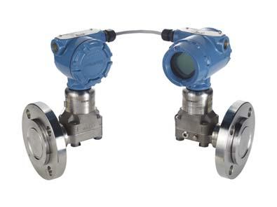
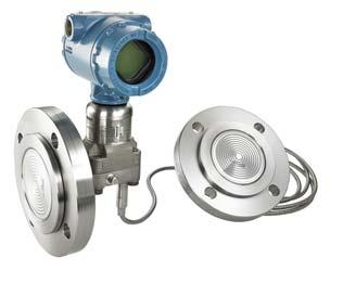
3 1.0 Introduction Quick Start Guide A remote seal system consists of a pressure transmitter, a remote seal, and either a direct mount or capillary style connection filled with a secondary fill fluid. During operation, the thin, flexible diaphragm and fill fluid separate the pressure sensor of the transmitter from the process medium. The capillary tubing or direct mount flange connects the diaphragm to the transmitter. When process pressure is applied, the diaphragm is displaced, transferring the measured pressure through the filled system, by way of the capillary tubing, to the transmitter. This transferred pressure displaces the sensing diaphragm in the pressure sensor of the transmitter. This displacement is proportional to the process pressure and is converted electronically to an appropriate output current and/or digital protocol. Figure 1. Path of Pressure in a Standard DP Level Seal System E C A B D A A. Pressure B. Process isolating diaphragm C. Transmitter diaphragm D. Fill fluid E. Transmitter pressure sensor 2.0 Preface This guide is designed to assist with general handling and installation instructions for the Rosemount DP Level Transmitters and 1199 Diaphragm Seal Systems. The Rosemount DP Level Transmitters and 1199 Diaphragm Seal Systems Reference Manual contains supplemental information about the seal system assemblies that are not covered in the corresponding transmitter manuals. 3
4 Quick Start Guide 3.0 General handling overview Check if equipment received conforms to the order. If any issues, contact your local Emerson sales representative immediately. When unpacking or handling seal system assemblies, do not lift the seal or transmitter by gripping the capillaries, doing so could result in disconnecting the seal and/or capillary from the transmitter, which will void the warranty. The material of a remote seal is designed to withstand pressure and wear from process material, but outside of process connection conditions, remote seals are delicate and should be handled with care. The protective cover should remain on the seal until the moment before installation. Try to avoid touching the diaphragm with fingers or objects and refrain from setting the diaphragm side of the seal down on a hard surface. Even minor dents or scratches in the diaphragm material may impair the performance of the seal system assembly. Avoid sharply bending or crimping the capillary tubing. The minimum bending radius of the capillary tubing is 3-in. (8 cm). When using heat or steam tracing, exercise caution if PVC coating is added onto capillary. The PVC coating on the armor will break down at temperatures around 212 F (100 C). Best practice for heat and steam tracing is to regulate the temperature above the maximum ambient temperature for a consistent result. To avoid accuracy effects and thermal stress, the capillary should not be partially heated. 4.0 Mechanical installation NOTICE Never attempt to disconnect the seals or capillaries from the transmitter or loosen bolts. Doing so will result in loss of fill fluid and will void the product warranty. 4.1 Mounting the seal system in vacuum applications Mounting the pressure transmitter at or below the bottom vessel tap is an important factor to ensure a stable measurement with vacuum applications. The static pressure limit for a differential pressure transmitter is 0.5 psia (25 mmhga), which ensures the transmitter sensor module fill fluid remains within the liquid phase of the vapor pressure curve. If the vessel static limit is below 0.5 psia, mounting the transmitter below the bottom tap provides a capillary fill fluid head pressure on the module. A general rule in vacuum applications is to mount the transmitter approximately 3 ft. (1 m) below the bottom tap of the vessel. Capillaries are to be securely fastened in order to avoid false readings. 4

5 Quick Start Guide 4.2 Insulation considerations with a Thermal Range Expander seal system The Thermal Range Expander System uses the heat from the process in order to keep both fluids within the system functioning properly, therefore insulation is not always required. However, it is always best practice to insulate systems to keep them functioning with optimum performance. The Thermal Range Expander should never be insulated above the line marked on the seal itself, see the figure below for reference. Figure 2. Thermal Range Expander System Insulation Considerations 4.3 Flanged type seals Gaskets When installing remote seal systems which employ a gasket or a gasket and flushing connection ring, make sure the gasket is aligned properly on the gasket sealing surface. Failure to properly install the gasket may cause process leaks, which can result in death or serious injury. In addition, make sure the gasket does not press down upon the diaphragm face. Anything pressing on the diaphragm will be read by the transmitter as pressure. A misaligned gasket may cause a false reading or damage the diaphragm. The diaphragm gasket is supplied when a lower housing or flushing connection is provided. The default gaskets are listed below, based on seal type. The process gasket must be supplied by the end user. Tantalum diaphragms are not supplied with default gasket, so a gasket option must be selected when applicable. 5
6 Quick Start Guide Table 1. Gasket Materials Seal type Gaskets Flanged seals assemblies FFW Thermo-Tork TN-9000 RFW Klinger C-4401 EFW PFW Thermo-Tork TN-9000 FCW RCW Klinger C-4401 FUW/FVW Threaded seal assemblies RTW Klinger C-4401 HTS Hygienic seal assemblies SCW (1) SSW STW EES VCS (1) SVS (1) SHP SLS (1) MLS (1) Specialty seals Ethylene propylene O-ring Ethylene propylene O-ring WSP Klinger C-4401 UCP Barium-Sulfate filled PTFE O-ring CTW TFW WFW Klinger C Ensure to use EHEDG approved gasket for EHEDG conformity. 6
7 Quick Start Guide Maximum working pressure (MWP) Verify the MWP as marked on the transmitter neck label meets or exceeds the expected maximum process pressure the transmitter/seal assembly could experience once installed. If a flushing ring is used, its MWP should also be verified. Bolt torquing When connecting the process and mating flange, the bolts should be torqued to the applicable flange requirements. Required torque is a function of the gasket material and surface treatment of the bolts and nuts which are customer supplied. 4.4 Pancake type seal options Capillary support tube A common option for the pancake type seal (PFW) is the capillary support tube. Due to the side capillary-to-seal connection, the support tube provides a handle for aligning the pancake seal during installation. The support tube should not be used for supporting any weight above that of the remote seal. Process flange Emerson offers the option of supplying the process flange, otherwise the process flange is furnished by the customer. For certain pancake seal assemblies, the Emerson supplied process flange has a machined hole through the center of the flange. This hole corresponds to a threaded connection in the back of the pancake seal upper housing. The flange can, therefore be connected to the seal prior to installation to make handling easier. 4.5 Threaded type seals Lower housing installation procedure The lower housing of the remote seal has either a male or female thread connection for attachment to a process pipe nipple. When threading the lower housing to the process pipe, care should be taken not to overtighten. The applied torque should comply to ANSI B for NPT connections or applicable torque requirements for pipe connections. Upper housing installation procedure The threaded seal is supplied with carbon steel, bolts, and nuts. 304 SST or 316 SST bolts and nuts can be ordered as options. The torque specifications for the RTW seal can be found in the table below. Gasket installation Threaded seals with flushing connection rings come with a sealing gasket. When connecting the remote seal, gasket, and flushing connection ring make sure the gasket is properly aligned on the gasket sealing surface. 7
8 Quick Start Guide Table 2. Gasket Specifications PSIG rating Bolt material Torque specification 2500 CS or SST 23 ft-lbs 5000 CS 53 ft-lbs 5000 SST 50 ft-lbs CS (SST N/A) 105 ft-lbs Alternative system installation procedure An alternative to threading the entire seal system assembly to the process piping is to unbolt the seal upper and lower housing and thread the lower housing to the hard piping separately. Bolt the upper and lower housings together to the required torque specification. Note that gaskets need to be replaced once they have been torqued. Thus this alternative system installation procedure requires gasket replacement. 4.6 Hygienic type seals Hygienic approvals Supplied 3-A approved hygienic seals are marked with a 3-A symbol. Supplied EHEDG approved hygienic seals are marked with a EHEDG symbol. Clamp style tank spud For clamp style tank spud seals the procedures for welding the tank spud to the tank vessel are shipped with the tank spud. For the welding procedure refer to Rosemount DP Level Transmitters and 1199 Diaphragm Seal Systems Reference Manual for proper welding tank spud guidelines. The clamp and gasket are furnished by the user. Maximum pressure rating of the system is dependent upon the clamp device. The clamp and O-ring are provided with the tank spud seal. Attach the clamp and hand-tighten the connection. Flange style tank spud When connecting the process and mating flange, the bolts should be torqued to the specifications outlined by ANSI B16.5 or applicable flange requirements. 4.7 Saddle type seals Lower housing installation procedure For 4-in. line size, the lower housing is welded directly into the process pipe. For 2- and 3-in. line sizes, the lower housing is welded onto the process pipe. The upper housing must be removed from the system when welding the lower housing into the process pipe. Allow the pipe connection to cool before installing the seal upper housing. 8
9 Quick Start Guide Upper housing installation procedure The torque specifications for the saddle seal upper housings is 180 in-lb. (20 N-m) for all bolting material. As it is necessary for the customer to torque the upper housing bolts during installation, each saddle seal includes a torque label with the specified torque. Gasket installation The saddle type seal comes standard with a sealing gasket. When connecting the upper and lower housings make sure the gasket is aligned properly on the gasket sealing surface. 4.8 TFS wafer style in-line seal Connection styles The in-line flow-through seal is attached to the process piping by flange, clamp, or male threaded connections. Flanged type connection The flow-through seal comes between the two process flanges due to the flanged process connection. The bolts should be torqued to the specifications outlined by ANSI B16.5 or EN , JIS B 2210 flange torque requirements. Required torque is a function of the gasket material and surface treatment of the bolts and nuts, which are customer supplied. 5.0 Ranging the transmitter Rosemount DP Level Transmitters and 1199 Diaphragm Seal Systems Reference Manual for proper ranging guidelines for open tank-single seal and pressurized tank-two seals. 6.0 Rosemount 1199 seal types 6.1 Flanged seal assemblies FFW Flush Flanged Seal RFW Flanged Seal EFW Extended Flanged Seal PFW Pancake Seal FCW Flush Flanged Seal - Ring Type Joint (RTJ) Gasket Surface RCW Ring Type Joint (RTJ) Flanged Seal FUW and FVW Flush Flanged Type Seals 6.2 Threaded seal assemblies RTW Threaded Seal HTS Male Threaded Seal 9
10 Quick Start Guide 6.3 Hygienic seal assemblies SCW Hygienic Tri-Clover Style Tri Clamp Seal SSW Hygienic Tank Spud Seal STW Hygienic Thin Wall Tank Spud Seal EES Hygienic Flanged Tank Spud Extension Seal VCS Tri Clamp In-Line Seal SVS VARIVENT Compatible Hygienic Connection Seal SHP Hygienic Cherry-Burrell I Line Seal SLS Dairy Process Connection - Female Thread Seal per DIN Specialty seal assemblies WSP Saddle Seal UCP Male Threaded Pipe Mount Seals and PMW Paper Mill Sleeve Seals CTW Chemical Tee Seal TFS Wafer Style In-Line Seal WFW Flow-Thru Flanged Seal 10
11 Quick Start Guide 11
12 * * Quick Start Guide , Rev DA Global Headquarters Emerson Automation Solutions 6021 Innovation Blvd. Shakopee, MN 55379, USA or North America Regional Office Emerson Automation Solutions 8200 Market Blvd. Chanhassen, MN 55317, USA or Latin America Regional Office Emerson Automation Solutions 1300 Concord Terrace, Suite 400 Sunrise, FL 33323, USA Europe Regional Office Emerson Automation Solutions Neuhofstrasse 19a P.O. Box 1046 CH 6340 Baar Switzerland +41 (0) (0) Asia Pacific Regional Office Emerson Automation Solutions 1 Pandan Crescent Singapore Enquiries@AP.Emerson.com Middle East and Africa Regional Office Emerson Automation Solutions Emerson FZE P.O. Box Jebel Ali Free Zone - South 2 Dubai, United Arab Emirates RFQ.RMTMEA@Emerson.com Linkedin.com/company/Emerson-Automation-Solutions Twitter.com/Rosemount_News Facebook.com/Rosemount Youtube.com/user/RosemountMeasurement Google.com/+RosemountMeasurement Standard Terms and Conditions of Sale can be found on the Terms and Conditions of Sale page. The Emerson logo is a trademark and service mark of Emerson Electric Co. Rosemount and Rosemount logotype are trademarks of Emerson. VARIVENT is a registered trademark of GEA Process Engineering Limited. Thermo-Tork is a registered trademark of Armstrong World Industries, Inc. All other marks are the property of their respective owners Emerson. All rights reserved.
, General Instructions for Handling and Installation of Rosemount 1199 Seal Systems
 Quick Installation Guide August 2011 Rosemount 1199 General Instructions for Handling and Installation of Rosemount 1199 Seal Systems Start Introduction Preface General Handling Overview Mechanical Installation
Rosemount 405 Compact Primary Element. Quick Start Guide , Rev HA June 2016
 Rosemount 405 Compact Primary Element 00825-0100-4810, Rev HA NOTICE This guide provides basic guidelines for Rosemount 405. It does not provide instructions for configuration, diagnostics, maintenance,
Rosemount Manifolds. Product Data Sheet April , Rev PC. Factory assembled, leak-tested, and calibrated
 Product Data Sheet pril 2015 00813-0100-4733, Rev PC Rosemount Manifolds Factory assembled, leak-tested, and calibrated Full breadth of offering including integral, conventional, and in-line designs Integral
Quick Start Guide , Rev FB June Rosemount 485 Annubar Flanged Flo-Tap Assembly
 Quick Start Guide 00825-000-809, Rev FB Rosemount 85 Annubar Flanged Flo-Tap Assembly Quick Start Guide NOTICE This guide provides basic guidelines for Rosemount 85 Annubar. It does not provide instructions
Quick Start Guide , Rev AB June Rosemount 585 Annubar Flanged Assembly
 Quick Start Guide 00825-0100-585, Rev AB Rosemount 585 Annubar Flanged Assembly Quick Start Guide NOTICE This guide provides basic guidelines for Rosemount 585 Annubar Assembly. It does not provide instructions
Rosemount Smart Pressure Gauge
 Rosemount Smart Pressure Gauge Product Data Sheet September 2017 00813-0100-4145, Rev AA The Rosemount Smart Pressure Gauge from Emerson utilizes industry-proven Rosemount pressure sensor technology to
Rosemount 3095FC MultiVariable Mass Flow Transmitter
 Quick Start Guide 00825-0100-4832, Rev CA Rosemount 3095FC MultiVariable Mass Flow Transmitter with Modbus Protocol Quick Start Guide NOTICE This guide provides basic guidelines for the Rosemount 3095FC
Rosemount DP Level Transmitters and Remote Seals
 FOR ROSEMOUNT 3051S, 3051, AND 2051 TRANSMITTERS APPLICATIONS Level, Flow, Pressure, Interface, Density Extreme hot and cold temperatures Corrosive, clogging, or viscous processes Hygienic requirements
Rosemount Manifolds. Rosemount Manifolds. Product Data Sheet , Rev NB January Contents
 Product Data Sheet Factory assembled, leak-tested, and calibrated Full breadth of offering including integral, conventional, and inline designs Integral design enables flangeless valve integration 2, 3,
Rosemount Manifolds. Product Data Sheet October , Rev PB. Factory assembled, leak-tested, and calibrated
 Product Data Sheet October 2014 00813-0100-4733, Rev PB Rosemount Manifolds Factory assembled, leak-tested, and calibrated Full breadth of offering including integral, conventional, and in-line designs
Rosemount Manifolds. Product Data Sheet September , Rev PA. Factory assembled, leak-tested, and calibrated
 Product Data Sheet September 2014 00813-0100-4733, Rev PA Rosemount Manifolds Factory assembled, leak-tested, and calibrated Full breadth of offering including integral, conventional, and in-line designs
Rosemount Manifolds. Rosemount Manifolds. Product Data Sheet , Rev MA August Contents
 Product Data Sheet Factory assembled, leak-tested, and calibrated Full breadth of offering including integral, conventional, and inline designs Integral design enables flangeless valve integration 2, 3,
Installation/Start-up Manual CMB_MAN_ABR_CH88 September CH88 In-Situ Combustion O2. Analyzer System
 CH88 In-Situ Combustion O2 Analyzer System Section 1: Section 2: Section 3: Section 4: Section 5: Section 6: Contents General Information Essential Instructions... 2 Symbols used... 3 Overview... 4 System
Endurance TM Conductivity Sensors
 Endurance TM Conductivity Sensors For additional information, please visit our website at EmersonProcess.com/LiquidAnalysis. Quick Start Guide Part Number: 51A-400/400VP, Rev. S March 2016 Sensor/process
Rosemount 228. Toroidal Conductivity Sensor. Product Data Sheet July Series LIQ-PDS-228
 LIQ-PDS-228 Product Data Sheet Rosemount 228 Toroidal Conductivity Sensor A Versatile Conductivity Sensor for Solving Diverse Application Challenges Rosemount 228 toroidal conductivity sensors reliably
Selection and Types of 1199 Remote Mount Seal Systems
 General Specifications and Datasheet 1199 Diaphragm Seal GSD- 1199DS-EV01 Selection and Types of 1199 Remote Mount Seal Systems Product Introduction Differential pressure transmitter assembly with remote
Rosemount 485 Annubar Threaded Flo-Tap Assembly
 Quick Installation Guide 00825-0500-809, Rev DB Threaded Flo-Tap 85 Annubar Rosemount 85 Annubar Threaded Flo-Tap Assembly Step 1: Location and Orientation Step 2: Weld Mounting Hardware Step 3: Install
Rosemount 585 Annubar Flanged Flo-Tap Assembly
 Quick Installation Guide 00825-0200-585, Rev AA Flanged Flo-Tap 585 Annubar Rosemount 585 Annubar Flanged Flo-Tap Assembly Start Step 1: Location and Orientation Step 2: Weld Mounting Hardware Step 3:
Triple offset technology for lower pressures.
 Triple offset technology for lower pressures. Vanessa Series 30-RS Triple Offset Valves A triple offset valve designed for the specific needs of general applications in lower pressure classes. Emerson.com/FinalControl
Rosemount 485 Annubar Flanged Assembly
 Quick Installation Guide 00825-0100-809, Rev DB Flanged 85 Annubar Rosemount 85 Annubar Flanged Assembly Start Step 1: Location and Orientation Step 2: Drill Holes into Pipe Step 3: Assemble and Check
Sanitary Seals. Dimensional Drawing for VCS Sanitary In-Line Diaphragm Seal Process wetted surface finish max. Ra of 32 µ in. 1.
 Sanitary Seals TRI-LMP IN-LINE (VS) SEL Dimensional Drawing for VS Sanitary In-Line Diaphragm Seal Process wetted surface finish max. Ra of 32 µ in. 1.5 (38,1) O dod L 3.54 (90,0) Dimensions are in inches
Rosemount 285 Annubar Pak-Lok Assembly
 Quick Installation Guide 0025-0100-02, Rev AA Pak-Lok 25 Annubar Rosemount 25 Annubar Pak-Lok Assembly Start Step 1: Location and Orientation Step 2: Drill Holes into Pipe Step 3: Weld Mounting Hardware
SHDP/GP Differential Pressure/Pressure Transmitter with Remote Diaphragm seals
 SHDP/GP Differential Pressure/Pressure Transmitter with Remote Diaphragm seals SHDP/GP Differential Pressure/Pressure Transmitter with Remote Diaphragm seals provides a kind of reliable measuring way to
Rosemount 485 Annubar Pak-Lok Assembly
 Quick Installation Guide 00825-0300-809, Rev EA Pak-Lok 85 Annubar Rosemount 85 Annubar Pak-Lok Assembly Start Step 1: Location and Orientation Step 2: Drill Holes into Pipe Step 3: Weld Mounting Hardware
Innovation in actuation.
 Innovation in actuation. Keystone EPI-2 Quarter Turn Electric Actuators Control your low-torque quarter turn valves and dampers more effectively, even in the largest plants. A world of experience Keystone
Rosemount Manifolds. Rosemount Manifolds. Product Data Sheet , Rev LA Catalog Contents
 Product Data Sheet Factory assembled, leak-tested, and calibrated Full breadth of offering including integral, conventional, and inline designs Integral design enables flangeless valve integration 2, 3,
Rosemount DP Level Transmitters and 1199 Seal Systems
 Product Data Sheet FOR ROSEMOUNT 3051S, 3051, AND 2051 TRANSMITTERS APPLICATIONS Level, Flow, Pressure, Interface, Density Extreme hot and cold temperatures Corrosive, clogging, or viscous processes Hygienic
Rosemount Pipe Clamp RTD Sensor
 Product Data Sheet Platinum RTD Temperature Sensors with silver or nickel tip Non intrusive design for measurement on pipe applications Temperature-sensor matching provides increased measurement accuracy
Rosemount DP Level Transmitters and 1199 Diaphragm Seal Systems
 Rosemount DP Level Transmitters and 1199 Diaphragm Seal Systems Product Data Sheet December 2017 00813-0100-4016, Rev RF Applications Level, flow, pressure, interface, density Extreme hot and cold temperatures
Rosemount 2160 Wireless Vibrating Fork Liquid Level Switch
 Technical Note Communicate Rosemount 2160 Rosemount 2160 Wireless Vibrating Fork Liquid Level Switch The Rosemount 2160 Wireless Level Switch is based on vibrating short fork technology, and is designed
Rosemount DP Level Transmitters and 1199 Remote Seals
 Product Data Sheet FOR ROSEMOUNT 3051S, 3051, AND 2051 TRANSMITTERS APPLICATIONS Level, Flow, Pressure, Interface, Density Extreme hot and cold temperatures Corrosive, clogging, or viscous processes Hygienic
Rosemount DP Level Transmitters and 1199 Diaphragm Seal Systems
 Rosemount DP Level Transmitters and 1199 Diaphragm Seal Systems Product Data Sheet March 2017 00813-0100-4016, Rev RD Applications Level, flow, pressure, interface, density Extreme hot and cold temperatures
Rosemount TM 222 Toroidal Flow-Through Conductivity Sensor. Instruction Manual LIQ-MAN-222 Rev.D June 2017
 Rosemount TM 222 Toroidal Flow-Through Conductivity Sensor Instruction Manual LIQ-MAN-222 Rev.D June 2017 SPECIFICATIONS Wetted Materials: Teflon-lined carbon steel pipe, with carbon steel outer flanges.
Rosemount Compact Vibrating Fork Liquid Level Switch. Product Data Sheet July , Rev EA
 Product Data Sheet 00813-0100-4029, Rev EA Compact Vibrating Fork Liquid Level Switch Virtually unaffected by turbulence, foam, vibration, coating, or changing liquid properties Built in diagnostics continuously
Rosemount 1810 Flush Mount Pressure Transmitter ROSEMOUNT 1810 FEATURES:
 Rosemount 1810 Rosemount 1810 Flush Mount Pressure Transmitter ROSEMOUNT 1810 FEATURES: A cleanable and compact stainless steel design An innovative patented venting configuration that prevents gauge reference
Rosemount 3051S Electronic Remote Sensor (ERS) System
 System") Rosemount 3051S Electronic Remote Sensor (ERS) System The Rosemount 3051S ERS System is a flexible, 2-wire 4-20 ma ART architecture that calculates differential pressure (DP) electronically using two pressure
Rosemount 3051S Electronic Remote Sensor (ERS) System The Rosemount 3051S ERS System is a flexible, 2-wire 4-20 ma ART architecture that calculates differential pressure (DP) electronically using two pressure
Rosemount 285 Annubar Primary Element Series
 0013-0100-02, Rev CA Rosemount 25 Annubar Primary Element Series Designed for general purpose applications Increased plant uptime with the maintenance-free design Energy savings gained through minimal
DRAFT. Installation, Operation and Maintenance Instructions for Emerson KBG-V Series
 Part Number: KBG-V.IOM.1001, Rev. 0 Release: February 2017 Installation, Operation and Maintenance Instructions for Emerson KBG-V Series DRAFT Part Number: KBG-V.IOM.1001, Rev. 0 Table of Contents February
Rosemount DP Level Transmitters and 1199 Seal Systems
 Rosemount DP Level Transmitters and 1199 Seal Systems Product Data Sheet November 2013 00813-0100-4016, Rev NA Applications Level, Flow, Pressure, Interface, Density Extreme hot and cold temperatures Corrosive,
Rosemount 402 and 402VP
 Rosemount 402 and 402VP Contacting Conductivity Sensors Instruction Manual LIQ-MAN-402 Rev. M May 2017 hasgkas Essential Instructions Read this page before proceeding! Emerson designs, manufactures and
Rosemount 9901 Chamber for Process Level Instrumentation
 Product Data Sheet Rosemount 9901 Rosemount 9901 Chamber for Process Level ation Allows external mounting of process level instrumentation Enables live maintenance Designed to ASME 31.3 Process Piping
1495 Orifice Plate 1496 Flange Union 1497 Meter Section Installation & Operation Manual
 00809-0100-4792 DS-4127 English Rev. AA 1495 Orifice Plate 1496 Flange Union 1497 Meter Section Installation & Operation Manual COMPLETE POINT SOLUTIONS PRINTED Product Manual Model 1495 Orifice Plate
Disassembly and Reassembly for WG Series Worm Gear Operator. User Instructions Part Number: XXXXXX, Rev. 0 Release: February 2017
 Disassembly and Reassembly for WG Series Worm Gear Operator User Instructions Part Number: XXXXXX, Rev. 0 Release: February 2017 User Instructions Doc. Number: XXXXXXXX Table of Contents February 2017,
Rosemount 9901 Chamber for Process Level Instrumentation
 Product Data Sheet Rosemount 9901 Rosemount 9901 Chamber for Process Level ation Allows external mounting of process level instrumentation Enables live maintenance Designed to ASME 31.3 Pressure Equipment
Rosemount Wireless Pressure Gauge
 Product Data Sheet January 2018 00813-0100-4045, Rev DA Rosemount Wireless Pressure Gauge with WirelessHART Protocol The Rosemount Wireless Pressure Gauge from Emerson utilizes industry-proven Rosemount
Technical Data Sheet PS , Rev C May Micro Motion R-Series Coriolis Flow and Density Meters
 Technical Data Sheet PS-001945, Rev C May 2017 Micro Motion R-Series Coriolis Flow and Density Meters R-Series Coriolis Flow Meters May 2017 Detailed Specifications R-Series accuracy Model Liquid mass
Type 289RC Exhaust Booster
 Instruction Manual D102588X012 Type 289RC January 2018 Type 289RC Exhaust Booster Figure 1. Type 289RC Exhaust Booster Introduction Scope of the Manual This manual describes the principles of operation
Rosemount DP Level Transmitters and 1199 Seal Systems
 Rosemount DP Level Transmitters and 1199 Seal Systems Product Data Sheet March 2015 Applications Level, Flow, Pressure, Interface, Density Extreme hot and cold temperatures Corrosive, clogging, or viscous
Top Mount Installation for DP Flowmeters in Steam Service
 00870-0200-4809 July 2009 Page 1 Top Mount Installation for DP Flowmeters in Steam Service This paper discusses installation of Rosemount Annubar and Compact Primary Element products above the pipe in
Safety and Relief Valves for Industrial and Commercial Applications.
 Safety and Relief Valves for Industrial and Commercial Applications. Kunkle Safety and Relief Valve Products Overview Kunkle Safety and Relief Valve Products Overview Contents Models 1 and 2 Brass Safety
RTD and Thermocouple Assemblies Reference Manual
 RTD and Thermocouple Assemblies Reference Manual www.rosemount.com RTD and Thermocouple Mounting and Installation Advice for Resistance Thermometers and Thermocouple Assemblies NOTICE Read this manual
Rosemount 3095FC MultiVariable Mass Flow Transmitter with MODBUS Protocol
 Quick Installation Guide Rosemount 3095FC Rosemount 3095FC MultiVariable Mass Flow Transmitter with MODBUS Protocol Step 1: Mount the Transmitter Step 2: Connect Wiring Step 3: Set Jumpers and Apply Power
Baumann 24000F Wafer Control Valve
 Instruction Manual 24000F Valves Baumann 24000F Wafer Control Valve Contents Introduction... 1 Scope of Manual... 1 Safety Precautions... 2 Maintenance... 2 Installation... 3 Air Piping... 3 Disassembly...
Rosemount Multipoint Thermocouple and RTD Profiling Sensors
 Product Data Sheet FEATURES Efficiently monitor a temperature profile for a wide range of applications, including hot-spot detection in reactors Single process insertion for up to 60 independent measurement
Micro Motion F-Series Coriolis Flow and Density Sensors. Installation Manual , Rev CC December 2010
 Micro Motion F-Series Coriolis Flow and Density Sensors Installation Manual 20002298, Rev CC December 2010 Safety and approval information This Micro Motion product complies with all applicable European
Rosemount 1195 Integral Orifice Primary Element
 September 2014 Rosemount DP Flow Rosemount 1195 Integral Orifice Primary Element Rosemount 1195 Integral Orifice Primary Element utilizes a self centering orifice plate design to eliminate installation
DIAPHRAGM SEALS Measuring your world since 1965
 INSTRUMENTS Measuring your world since 1965 DIAPHRAGM SEALS MADE IN THE USA Measuring your world since 1965 REOTEMP DIAPHRAGM SEALS WHY A DIAPHRAGM SEAL? Diaphragm seals are used in applications where
Rosemount 3095FT MultiVariable Flow Data Logger
 Quick Installation Guide Rosemount 3095FT Rosemount 3095FT MultiVariable Flow Data Logger Step 1: Mount the Transmitter Step 2: Consider Housing Rotation Step 3: Set Jumpers and Switches Step 4: Connect
Pressure Measurement Remote seals for transmitters and pressure gauges
 Siemens pplication The remote seals MF.. can be fitted to SITRNS P transmitters for pressure (SITRNS P, P, DSIII and P), absolute pressure (SITRNS P and DSIII) and differential pressure and flow (SITRNS
Types 1808 and 1808A Pilot-Operated Relief Valves or Backpressure Regulators
 Instruction Manual Form 5116 Types 1808 and 1808A July 2010 Types 1808 and 1808A Pilot-Operated Relief Valves or Backpressure Regulators! Warning Failure to follow these instructions or to properly install
Installation, Operation and Maintenance Manual DOC.IOM.MO.E October MO-Series Manual Override Gearboxes
 Installation, Operation and Maintenance Manual DOC.IOM.MO.E October 2017 MO-Series Manual Override Gearboxes EL Matic TM Installation, Operation and Maintenance Manual Table of Contents DOC.IOM.MO.E Rev.
289 Series Relief Valves
 Instruction Manual Form 174 89 Series May 013 89 Series Relief Valves! WARNING Failure to follow these instructions or to properly install and maintain this equipment could result in an explosion and/or
Rosemount Orifice Series Differential Pressure Flow
 Rosemount Orifice Series Differential Pressure Flow Innovative Offering for Better Measurement Revolutionizing the Industry Workhorse Orifice Plate Technology It s no coincidence that orifice plates are
Bettis RGS Q-Series. Quarter-Turn Spring-Return (SR) and Double-Acting (DA) Pneumatic Actuators. Product Data Sheet April 2016 RGS Rev.
 and Double-Acting (DA) Pneumatic Actuators. Product Data Sheet April 2016 RGS Rev.") Quarter-Turn Spring-Return (SR) and Double-Acting (DA) Pneumatic Actuators Output Torques to 21,000 in-lb (2373 N m) Ductile Iron or Stainless-Steel Construction Temperatures from -60 F to 450 F (-51 C
Quarter-Turn Spring-Return (SR) and Double-Acting (DA) Pneumatic Actuators Output Torques to 21,000 in-lb (2373 N m) Ductile Iron or Stainless-Steel Construction Temperatures from -60 F to 450 F (-51 C
Fisher 644 and 645 Differential Pressure Pump Governors
 Instruction Manual 644 and 645 Pump Governors Fisher 644 and 645 Differential Pressure Pump Governors Contents Introduction... 1 Scope of Manual... 1 Description... 1 Specifications... 2 Educational Services...
Baumann Way Control Valve
 Instruction Manual 24003 Valve Baumann 24003 3-Way Control Valve Contents Introduction... 1 Scope of Manual... 1 Safety Precautions... 2 Educational Services... 3 Maintenance... 3 Installation... 3 Air
Pressure control solutions for your industry. Aerospace & Defense
 Pressure control solutions for your industry. Aerospace & Defense Years of experience innovative solutions TESCOM is an experienced provider of high quality regulators, valves, manifolds, custom assemblies
Electromagnetic Flow Meter Owner s Manual HARDWARE
 Electromagnetic Flow Meter Owner s Manual HARDWARE Compact Magnetic Flowmeter (Flange Connection) Sanitary Magnetic Flowmeter (Tri clamp Connection) Part No. 910000 Rev.C Content 1. GENERAL INFORMATION...2
Type 310A-32A Pressure Reducing Regulator
 Bulletin 71.2 D102066X012 Type 310A February 2017 Type 310A-32A Pressure Reducing Regulator Figure 1. Type 310A Regulator with Type 32A Pilot Introduction The Type 310A pilot-operated high-pressure regulator
TYPE 2100 ELASTOMER BELLOWS UNITIZED SEAL Technical Specification
 A Face/Primary Ring B Seat/Mating Ring C Drive Band D Bellows E Spring D E B C A Product Description The Type 2100 is a compact, unitized, single spring, elastomer bellows mechanical seal. For centrifugal,
ES-665 Series Spring-Loaded Thief Hatch
 Instruction Manual D10416X01 ES-66 Series December 017 ES-66 Series Spring-Loaded Thief Hatch Table of Contents Introduction...1 Specifications... Principle of Operation... Tagging Information... Installation...
type 122a three-way Switching Valve
 Instruction Manual Form 2279 Type 122A January 2016 type 122a three-way Switching Valve! WarnIng Failure to follow these instructions or to properly install and maintain this equipment could result in
Fisher CAV4 Control Valve
 CAV Valve Product Bulletin Fisher CAV Control Valve The Fisher CAV control valve with Cavitrol IV trim is designed specifically for liquid applications, such as boiler feedwater recirculation, where pressure
Y610A, Y611A, and Y612A Series Vacuum Service Equipment and Relief Valves
 Y610A, Y611A, and Y612A Series Vacuum Service Equipment and Relief Valves July 2013 W1094_1 Figure 1. Type Y610A or Y610AP Vacuum Breaker Introduction The Y610A, Y611A, and Y612A Series devices (Figures
Railroad Ball Valves Series 5REB3
 Railroad Ball Valves Series 5REB3 4" (DN 00) Installation, Maintenance and Operating Instructions IMO-R4 /05 IMO-R4 Table of Contents GENERAL.................................... 3. Scope of the Manual........................
CombiTemp Temperature Measuring System
 CombiTemp Temperature Measuring ystem Flexible building block concept All wetted parts in acid-proof, stainless steel ome hygienic connections conform to -A standards, FDA demands and EHEDG guidelines
Fisher TBX Hydro Plug Fixture
 Instruction Manual TBX Hydro-Plug Fixture Fisher TBX Hydro Plug Fixture Contents Introduction... 1 Scope of Manual... 1 Description... 2 Educational Services... 2 Principle of Operation... 2 Maintenance...
CBA300 Series Pneumatic Actuators Improved Design - Compact, Lightweight To Suit All Applications And Environment
 CBA300 Series Pneumatic Actuators Improved Design - Compact, Lightweight To Suit All Applications And Environment Design and Construction Emerson is the global leader in valve automation, providing reliable
F-4600 INLINE ULTRASONIC FLOW METER Installation and Operation Guide
 F-4600 INLINE ULTRASONIC FLOW METER Installation and Operation Guide 11451 Belcher Road South, Largo, FL 33773 USA Tel +1 (727) 447-6140 Fax +1 (727) 442-5699 1054-7 / 34405 www.onicon.com sales@onicon.com
Rosemount 405 Compact Orifice Series
 Reference Manual Rosemount 405 Compact Rosemount 3051SFC Compact Orifice Flowmeter Rosemount 3095MFC Compact Orifice Mass Flowmeter www.rosemount.com Reference Manual Rosemount 405 Compact Rosemount 405
Micro Motion T-Series Straight-Tube Mass Flow and Density Meters. Product Data Sheet PS July 2001
 Micro Motion T-Series Straight-Tube Mass Flow and Density Meters Product Data Sheet PS-00371 July 2001 Micro Motion T-Series Straight-Tube Meters Micro Motion is proud to offer you the first single-straight-tube
Instrumentation Products Monoflanges & VariAS-Blocks
 Instrumentation Products Monoflanges & VariAS-Blocks Introduction Introduction The AS-Schneider Monoflanges and VariAS- Blocks are designed to overcome the problems of traditional assemblies on primary
Fisher 9500 Butterfly Control Valve
 9500 Product Bulletin Fisher 9500 Butterfly Control The Fisher 9500 butterfly valve is a fully lined valve for use with corrosive fluids and where tight shutoff is required. The nitrile or PTFE liner totally
Resistance Temperature Sensors for Hygienic and Sanitary Applications
 Product Data Sheet Resistance temperature sensors for applications in the food and beverage, pharmaceutical and life-science industries Aseptic process connections suitable for CIP and SIP dead-pocked
Line Blank Specification
 1.0 Purpose Line Blank Specification Page 1 of 14 1.1 This document provides specifications for line blanks (a.k.a. slip blanks, pancakes, paddle blanks) NPS 1/2 through NPS 24 up through Class 1500 and
Type 289P Pilot-Operated Relief Valve
 Instruction Manual D102680X012 Type 289P July 2017 Type 289P Pilot-Operated Relief Valve Figure 1. 1 NPT Type 289P Pilot-Operated Relief Valve Figure 2. 2 NPT Type 289P Pilot-Operated Relief Valve Introduction
Fisher CAV4 Control Valve
 Product Bulletin D10197X012 Fisher CAV Control Valve CAV Valve The Fisher CAV control valve (figure 1) with Cavitrol IV trim is designed specifically for liquid applications, such as boiler feedwater recirculation,
Y690A Series Pressure Reducing Regulators
 Instruction Manual Form 5463 Y690A Series February 2009 Y690A Series Pressure Reducing Regulators! Warning Fisher regulators must be installed, operated, and maintained in accordance with federal, state,
Rosemount Twisted Square Thermowells
 Product Data Sheet November 2017 00813-0300-4952, Rev AA Rosemount Twisted Square Thermowells Wide variety of industry standard process connections including flanged, threaded, welded, and Van Stone Large
Bettis GH-Series Pneumatic Spring-Return Actuator Torque Chart Imperial
 VA-DC-000-0179 Rev. 2 June 2017 Pneumatic Chart Imperial Copyright Emerson. The information in this document is subject to change without notice. Updated data sheets can be obtained from our website www.emerson.com/bettis
Fisher CVX Hydro Plug Fixture
 Instruction Manual CVX Hydro-Plug Fixture Fisher CVX Hydro Plug Fixture Contents Introduction... 1 Scope of Manual... 1 Description... 1 Educational Services... 2 Principle of Operation... 2 Maintenance...
Process Industry. Diaphragm Seal Solutions
 Process Industry Diaphragm Seal R Overview Diaphragm Seal Systems Provide Protection to Ensure Safety, Reliability Diaphragm seal systems protect gauges from hot, viscous, contaminated or corrosive media.
DIAPHRAGM SEALS. MHP SERIES MINI HIGH PRESSURE Mini diaphragm seal for pressures up to 6000 psi
 DIAPHRAGM SEALS seals, also referred to as isolators or chemical seals, are used to protect instruments from viscous, corrosive or very high temperature process media. PIC stocks, fills and calibrates
Mobrey MLT100. Displacer Level Transmitter. Product Data Sheet February 2015 IP119, Rev CA. Level, contents or interface measurement transmitter
 Product Data Sheet February 2015 IP119, Rev CA Displacer Level Transmitter Level, contents or interface measurement transmitter Direct or external chamber mounting 4 20 ma HART output ATEX Intrinsically
Model 3051 Sensor Module Replacement
 Model 3051 Sensor Module Replacement 00809-0400-4001 English Rev. BA SAFETY MESSAGES Procedures and instructions in this manual may require special precautions to ensure the safety of the personnel performing
Bettis TEC2 Electric Actuator with Model 500 Quick-Start Guide. Quick-Start Guide E2K Rev. 2 October 2017
 Bettis TEC2 Electric Actuator with Model 500 Quick-Start Guide Quick-Start Guide Quick-Start Guide Welcome to TEC2 Welcome to TEC2 The TEC2 actuator s Local Display Module (LDM) and Remote Display Module
Rosemount 1067 Compact Sensor and 1097 Thermowell
 Product Data Sheet Rosemount 1067 and 1097 Rosemount 1067 Compact Sensor and 1097 Thermowell RTD and Thermocouple single and dual sensor models (1067 Model) Wide selection of materials available for thermowells
EIM TEC2 Electric Actuator with Model 500 Quick-Start Guide
 Quick-Start Guide EIM TEC2 Electric Actuator with Model 500 Quick-Start Guide (Model 500 Discontinued) Quick-Start Guide Welcome to TEC2 Welcome to TEC2 The TEC2 actuator s Local Display Module (LDM)
Fisher RSS Lined Globe Valve
 Instruction Manual D0990 November 009 RSS Valve Fisher RSS Lined Globe Valve Contents Introduction............................... Scope of Manual.......................... Description...............................
IMO-200EN 09/2010. Trunnion mounted forged ball valves Model FF and GG. Installation, Maintenance and Operating Instructions IMO-200EN 09/2010
 IMO-200EN 09/2010 Trunnion mounted forged ball valves Model FF and GG Installation, Maintenance and Operating Instructions IMO-200EN 09/2010 2 IMO-200EN Table of Contents I GENERAL INFORMATION...................