TNV TIER3 INTRODUCTION
|
|
|
- Lester Barrett
- 5 years ago
- Views:
Transcription

1 TNV TIER3 INTRODUCTION

2 ECO governor system operation Actuator Eco-Governor Fuel Pomp Rack position Speed Intake EGR-Valve Re-circulation Exhaust Inj.Nozzle Liner Piston Key Switch Switch Starting Aid CW Temp. Display Starter Accelerator
= DisplacementLitre NV1 NV2 NV3 ECU Electronic")

3 NOx Reduce Measure ECO governor system operation =EGR (Exhaust Gas Recirculation)= DisplacementLitre NV1 NV2 NV3 ECU Electronic Control EGR Electronic Control EGR Valve Coolant temp. Intake Air Exhaust Gas Engine Speed Engine Load Output EGR domain Engine Speed
4 ECO governor system operation EGR valve EGR valve is operated by step motor. Valve opens with 54 steps and is controlled pending on engine speed and load factor (=determined as percentage from rack idl, max, min and Ract (relative to Rmin). Load factor is delivered as PWM signal from the E-ECU. Below 60 C EGR valve will not be opened.
5 ECO governor system operation CW Temp. CSD Accelerat or Actuator Act Fuel Spring Act Fuel Actuator Amp. Rack Position Speed Revolution Gear Rack
6 Battery Fuse:80A B S Fuse:10A Fuse:10A Fuse:60A R B BR C Key SW Pre Off On R B BR C ECO governor system operation Starter ( Yanmar genuineness) IG P Alternator Yanmar genuineness Starter Relay Main Relay Sub Relay Start Panel Starting aid Relay Air heater(500w) Rack actuator Relay Accel. sensor After heat option E7 E34 E20 E8 E10 E44 E38 E35 IGNSW MAIN-RLY APP-OP1 PREHT-LMP STARTSW RENRPM AIRHT-RLY AVCC APS VB E48 SHUDNSW FAIL- LMP LOAD- M NRPM -M E15 E23 E12 E32 E22 Engine stop 1 Pre- heat lamp Failure lamp Load monitor Engine speed monitor Fuel Injection Pump Rack Actuator Rack position Engine speed CSD E33 E42 E43 E36 E19 E18 E41 RACK- RLY RACKSOL AVB RPS NRPM NRPM - GND CSD- CL APP- OP2 APP- IP1 APP- IP7 APP- IP2 APP- IP3 APP- IP4 E2 E24 E13 E14 E9 E17 Speed selection lamp Droop switch Rmax1 switch Rmax2 switch Engine speed1 switch Engine speed2 switch CW Temp EGR Valve Marked w/ are necessary for engine control. E16 E28 E31 E21 E11 E1 E37 E26 E27 E25 RET GND- A STPM -A D REAN TAIR TEGR TW APP- IP5 APP- IP6 CANH RECAN CANL RxD TxD N.C. N.C. E5 E6 E40 E30 E39 E3 E4 E29 E46 Reverse Droop switch Speed selection switch Service tool Coupler Painting parts are necessary. GND E45 GND- P E47
7 (dis)advantages NEW technology Torque curve regulation Selective Governor Mode Img. Droop Const. regulation Iso-chronous Mech. Governor Droop Output ON = isochronous Speed Regulation is 0% on the speed (constant)
8 (dis)advantages NEW technology Torque curve regulation Selective Governor Mode Img. Droop Const. regulation Iso-chronous Mech. Governor Droop Output OFF = droop Speed Regulation is approx. 7% (=standard)
9 ECO governor system operation Transition control (avoid spill of fuel) Fuel Increase for Engine Start Fuel Injection Amount Mech.Gov. at Full - Throttle ECO Gov Engine Speed min -1 Excessive Fuel

10 ECO governor system operation Starter control Complete Rack Rack Self Test Self Test Starter Starter Starter Control Control ON maximum 1.0 Complete Engine Start min -1 Key SW Starting Aid Control Standard

 Speed Control External SW Setting CAN Sig. Compatible only NO type = terminal E13 Emg. Stop Speed Enable SW Turn.")
11 ECO governor system operation Engine SHDW Vcc Ext. SW Immobilizer NC Contact Engine STOP ECU Speed Control Function CAN Sig. Speed External SW Accelerator Speed Control / speed selection Deceleration Const. Speed 12 (ex:1800min ECU -1 ) Deceleration 2 Fail Safe Action Immobilizer Open : Engine STOP Emergency (option) E15 Short : Engine STOP STOP (STD) E13 Acceleration Accelerator Position Const. Speed 1 Const. One Touch Speed (ex:low idle) Speed Control External SW Setting CAN Sig. Compatible only NO type = terminal E13 Emg. Stop Speed Enable SW Turn.Back Deceleration Speed 1 SW Auto/One Touch Deceleration Speed 2 SW Speed Control off Engine STOP off Accelerator off off Deceleration 1 on on on off off on Deceleration 2 Const. Speed 1 on on Const. Speed 2 :Option :Generator Standard
12 ECO governor system operation Low (up) High (down) idle-speed Control option Cold State Shorten Warm up Reduce White Smoke WO Temp. WO Temp. Hi-idle Speed Purpose Speed Automatically Low-idle Manually Idle Speed Hi-idle Speed Down Low-idle Speed Up Accelerator Position WO Temp.
 t=80or Air Heater CW Pre Temp10 Heat ON Time is controlled by CW")

13 ECO governor system operation Starting Aid Control Standard Easy Cold Start After Heat ON (option) t=80or Air Heater CW Pre Temp10 Heat ON Time is controlled by CW Temp. Reduce Starting White Aid Smoke Lamp Pre Heat Time CW Temp. Air Heater Grow Glow PlugON Engine Key Under Start SW Starting Complete ON Air Heater Key SW CW Temp.
14
 Replacement Service tool and diagnostics Individual Control Controlled by model program map Comp.")
15 1 All the data including injection quantity is stored in Product Data Management(PDM) before shipping, therefore when replacing FOP, new compensation data shall be re-stored in PDM. FOP Database (PDM) Replacement Service tool and diagnostics Individual Control Controlled by model program map Comp. data Feedback Compensation data 2 Download Control program Map Compensation data Blank ECU When replacing ECU with new one in the field, the data shall be transferred from old one to new one or download the data for applicable engine serial number.
16 Service tool and diagnostics Function of Service tool Diagnosis Tool Yanmar s unique tool Converter Microsoft Windows PC (2000/XP) Tool software (CD-ROM etc. Adoption of KWP 2000 Keyword Protocol 2000 diagnosis Monitor display Error code display Test for diagnosis Data logging Special signal converter is required. Software can be distributed by CD-ROM and the Internet.
 WindowsPC Trouble Details Diagnostics Indicate in other")
17 Service tool and diagnostics Trouble Fail Safe Limp Home Engine Shut Down Customer Panel as much as possible keep running Blink Engine Trouble Lamp Indicate Trouble Group Service Tool Connector Adapter (USB-CAN) WindowsPC Trouble Details Diagnostics Indicate in other ECU
18 Service tool Customer Panel Service tool and diagnostics Blink Engine Trouble Lamp Indicate Trouble Group
19 Service tool Customer Panel Service tool and diagnostics Blink Engine Trouble Lamp Indicate Trouble Group Please explain what kind of failure is indicated?


![[ Configuration ]](/docs-images/84/89683904/images/20-2.jpg "Signal converter")

20 Service tool and diagnostics Service tool Diagnostic & monitoring software [ Configuration ] Signal converter Diagnosis tool kit Connecting wire CD-ROM Windows ECU
21 Service tool and diagnostics Historical Data Monitor Diagnostics Test
22 Service tool and diagnostics System details (Engine / FIE / ECU) ECU system / ECU ID information
23 troubleshooting What to do with the indicated failures? Indicated failure (=DTC or flash pattern) DTC detection conditions Operation condition Failure condition Test time Flash pattern required system setting. system / failure condition which causes the fault. minimum time needed to activate DTC number of flashes indicated Check point which parts / item to check
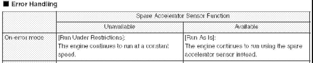
24 troubleshooting What to do with the indicated failures? Fault handling On-error mode Engine running mode when failure is active. as-is / restricted / stop Limited operation described how operation is restricted Fail release which setting is required to release the failure.


25 Indicated failure P0122/4 troubleshooting Low voltage for accelerator sensor
26 Indicated failure P0122/4 troubleshooting Low voltage for accelerator sensor Possible causes Accelerator sensor faulty Accelerator sensor signal wires disconnected or grounded. Input voltage (5V) signal disconnected or grounded Ground wire short cuts to power supply Check method Check accelerator sensor function (resistance value /continuity) Check accelerator sensor connection (disconnected or shortcut) Check E38 pin (disconnected or grounded) Check E28 pin (power supplied to pin)
27 Indicated failure P0122/4 troubleshooting Low voltage for accelerator sensor
28 troubleshooting Indicated failure P117/4 Indicated failure P0562/1 Low voltage for CW sensor Low power supply for ECU
series Complies with EPA Tier3 Complies Optionally ELECTRONIC CONTROL SYSTEM
 series ELECTRONIC CONTROL SYSTEM Complies with EPA Tier3 Complies Optionally Section 14 ELECTRONIC CONTROL SYSTEM TNV Application Manual Page Precautions on the use of electronic control components...
ENGINE CONTROL SYSTEM. 1. General ENGINE 3VZ FE ENGINE
 ENGINE 3VZ FE ENGINE 69 ENGINE CONTROL SYSTEM 1. General The engine control system for the 3VZ FE engine has the same basic construction and operation as for the 2VZ FE engine. However, the sequential
Diag. Code 71 EGR System Malfunction CIRCUIT DESCRIPTION. TR-92 ENGINE TROUBLESHOOTING - Circuit Inspection
 TR-92 EINE TROUBLESHOOTI - Circuit Inspection Diag. Code 71 EGR System Malfunction CIRCUIT DESCRIPTION The EGR system is designed to recirculate the exhaust gas properly controlled according to the driving
Hyundai - Specific Trouble Codes
 Hyundai - Specific Trouble Codes P1100 Map Sensor - Malfunction P1101 Map Sensor - Abnormal P1102 Map Sensor - Low Input P1103 Map Sensor - High Input P1104 Air Flow P1105 Air Flow - Abnormal P1106 Air
1. ENGINE ECU AND OTHER COMPONENTS
 09-3 EGINE CONTROL SYSTEM 1. ENGINE ECU AND OTHER COMPONENTS ECU/Barometric Sensor Camshaft Position Sensor HFM Sensor / Intake Air Temperature Sensor Fuel Filter (Water Sensor) Preheating Relay Accelerator
8/18/2017 Throttle Position Sensor TSB Title: 10-FL /18/2010 Engine Controls - MIL ON/DTC's P2135/P0638
 Vehicle» Powertrain Management» Computers and Control Systems» Throttle Position Sensor» Technical Service Bulletins» All Technical Service Bulletins» Engine Controls - MIL ON/DTC's P2135/P0638 Group:
SERVICE MANUAL. Common Rail System for NISSAN YD1-K2 Type Engine. Operation. For DENSO Authorized ECD Service Dealer Only
 For DENSO Authorized ECD Service Dealer Only Diesel Injection Pump No. E-03-01 SERVICE MANUAL Common Rail System for NISSAN YD1-K2 Type Engine Operation June, 2003 00400013E Foreword To meet the high pressurization
Diagnostic Trouble Code (DTC) List - Vehicle
 List - Vehicle") Document ID# 850406 2002 Pontiac Firebird Diagnostic Trouble Code (DTC) List - Vehicle DTC DTC 021 and/or 031 DTC 022 and/or 032 DTC 023 or 033 DTC 24/34 DTC 025 and/or 035 DTC 041 DTC 042 DTC 043 DTC
Document ID# 850406 2002 Pontiac Firebird Diagnostic Trouble Code (DTC) List - Vehicle DTC DTC 021 and/or 031 DTC 022 and/or 032 DTC 023 or 033 DTC 24/34 DTC 025 and/or 035 DTC 041 DTC 042 DTC 043 DTC
G - TESTS W/CODES - 2.2L
 G - TESTS W/CODES - 2.2L 1994 Toyota Celica 1994 ENGINE PERFORMANCE Toyota 2.2L Self-Diagnostics Celica INTRODUCTION If no faults were found while performing F - BASIC TESTING, proceed with self-diagnostics.
CANDO Diagnostic List Cummins_v8.27
 CANDO Diagnostic List Cummins_v8.27 Remark: 1. : means that the system has this function 2. - : means that the system does not have this function 3.compared with the last version, the new added function
SERVICE MANUAL. for MITSUBISHI L200/TRITON 4D56/4M41Engine OPERATION. Diesel Injection Pump DENSO INTERNATIONAL THAILAND CO., LTD.
 Diesel Injection Pump SERVICE MANUAL Common Rail System (HP3) for MITSUBISHI L200/TRITON 4D56/4M41Engine OPERATION June, 2005 DENSO INTERNATIONAL THAILAND CO., LTD. TG00400010E 2005 DENSO INTERNATIONAL
EMISSION CONTROL SYSTEM
 XJ EMISSION CONTROL SYSTEM 25-1 EMISSION CONTROL SYSTEM TABLE OF CONTENTS ON-BOARD DIAGNOSTICS 2.5L DIESEL ENGINE... 1 EXHAUST EMISSION CONTROLS 2.5L DIESEL ENGINE... 6 ON-BOARD DIAGNOSTICS 2.5L DIESEL
MULTIPOINT FUEL INJECTION (MPI) <4G9>
 <4G9>") MULTIPOINT FUEL INJECTION (MPI) 13C-1 MULTIPOINT FUEL INJECTION (MPI) CONTENTS GENERAL................................. 2 Outline of Changes............................ 2 GENERAL INFORMATION...................
MULTIPOINT FUEL INJECTION (MPI) 13C-1 MULTIPOINT FUEL INJECTION (MPI) CONTENTS GENERAL................................. 2 Outline of Changes............................ 2 GENERAL INFORMATION...................
DIAGNOSIS SYSTEM DESCRIPTION CHECK ENGINE WARNING LIGHT CHECK
 FI146 EFI SYSTEM (3VZE) DIAGNOSIS SYSTEM DESCRIPTION The engine (engine and ECT) ECU contains a builtin, selfdiagnosis system which detects troubles within the engine signal network and flashes the warning
EMISSION CONTROL SYSTEM
 XJ EMISSION CONTROL SYSTEM 25-1 EMISSION CONTROL SYSTEM CONTENTS EXHAUST EMISSION CONTROLS 2.5L DIESEL ENGINE... 6 ON-BOARD DIAGNOSTICS 2.5L DIESEL ENGINE... 1 ON-BOARD DIAGNOSTICS 2.5L DIESEL ENGINE INDEX
PRE CHECK 1. DIAGNOSIS SYSTEM
 DI710 w/o Tachometer: w/ Tachometer: F18894 PRECHECK ANTILOCK BRAKE SYSTEM DI8CS03 1. DIAGNOSIS SYSTEM (a) Check the indicator. When the ignition switch is turned, check that the ABS warning light is on
TROUBLESHOOTING FOR EFI ELECTRONIC CIRCUIT WITH VOLT/OHMMETER
 FI118 TROUBLESHOOTING FOR EFI ELECTRONIC CIRCUIT WITH VOLT/OHMMETER HINT: Because the following troubleshooting procedures are designed for inspection of each separate system, the actual troubleshooting
EG1 189 EFI SYSTEM 5S FE ENGINE DIAGNOSIS SYSTEM
 5SFE ENGINE EG1189 DIAGNOSIS SYSTEM DESCRIPTION The ECU contains a builtin selfdiagnosis system by which troubles with the engine signal network are detected and a CHECK engine warning light on the combination
A rotary solenoid type ISC system is used, which controls the fast idle and idle speeds.
 44 ENGINE 5S FE ENGINE ENGINE CONTROL SYSTEM 1. General Basic functions of the engine control system of the new 5S FE engine for the new Camry are the same as those in the 5S FE engine for the 90 model
DTC P0401 Exhaust Gas Recirculation Flow Insufficient Detected
 DIAGNOSTICS DI95 DI07W03 DTC P040 Exhaust Gas Recirculation Flow Insufficient Detected CIRCUIT DESCRIPTI The EGR system recirculates exhaust gas, which is controlled to the proper quantity to suit the
Error Codes TOYOTA SUPRA MA70
 Code Error 11 (+B) Error Codes TOYOTA SUPRA MA70 Momentary interruption in power supply to. Ignition switch circuit Ignition switch Main relay circuit Main relay 12 RPM Signal No "NE" or "G" signal to
COMMON RAIL SYSTEM (CRS)
") MITSUBISHI 4N13, 4N14 ENGINES COMMON RAIL SYSTEM (CRS) Issued : November 2010 Applicable Vehicle : Vehicle Manufacturer MITSUBISHI Vehicle Name LANCER ASX OUTLANDER 50000023E 2010 DENSO CORPORATION All
MITSUBISHI 4N13, 4N14 ENGINES COMMON RAIL SYSTEM (CRS) Issued : November 2010 Applicable Vehicle : Vehicle Manufacturer MITSUBISHI Vehicle Name LANCER ASX OUTLANDER 50000023E 2010 DENSO CORPORATION All
13A-1 FUEL CONTENTS MULTIPOINT FUEL INJECTION (MPI) FUEL SUPPLY... 13B
 FUEL SUPPLY... 13B") 13A-1 FUEL CONTENTS MULTIPOINT FUEL INJECTION (MPI)... 13A FUEL SUPPLY... 13B 13A-2 MULTIPOINT FUEL INJECTION (MPI) CONTENTS GENERAL INFORMATION... 3 SERVICE SPECIFICATIONS... 6 SEALANT... 6 SPECIAL TOOLS...
13A-1 FUEL CONTENTS MULTIPOINT FUEL INJECTION (MPI)... 13A FUEL SUPPLY... 13B 13A-2 MULTIPOINT FUEL INJECTION (MPI) CONTENTS GENERAL INFORMATION... 3 SERVICE SPECIFICATIONS... 6 SEALANT... 6 SPECIAL TOOLS...
GROUP 13Ab. 13Ab-2 CONTENTS TROUBLESHOOTING STRATEGY.. DATA LIST REFERENCE TABLE... 13Ab-29 TROUBLE CODE DIAGNOSIS...
 13Ab-1 GROUP 13Ab CONTENTS TROUBLESHOOTING STRATEGY.. 13Ab-2 DATA LIST REFERENCE TABLE... 13Ab-29 TROUBLE CODE DIAGNOSIS..... 13Ab-2 FAIL-SAFE FUNCTION REFERENCE TABLE........................ 13Ab-20 DIAGNOSTIC
ENGINE CONTROL SYSTEM
 08 5 ECU According to input signals from various sensors, engine ECU calculates driver s demand (position of the accelerator pedal) and then controls overall operating performance of engine and vehicle
VACUUM MODULATOR COMPOSITION. Layout. EGR valve. Turbocharger actuator. Vacuum pump hose Vacuum pump. Turbocharger vacuum modulator
 42 04 VACUUM MODULATOR COMPOSITION Layout Turbocharger actuator EGR valve Vacuum pump hose Vacuum pump Turbocharger vacuum modulator EGR vacuum modulator Vacuum Modulator for VGT Turbocharger Actuator
Manual. Engine SOLO type i
 for the Engine SOLO type Serial - no.... Manufactured... Aircraft - type... Registration no.... Owner... Log of revisions no. Edition date revised page no. date of entry 1 01.09.2010 1-9 01. September
DTC P0401 Exhaust Gas Recirculation Flow Insufficient Detected
 DIAGNOSTICS EINE (JZGTE) DI17 DI4T301 DTC P0401 Exhaust Gas Recirculation Flow Insufficient Detected CIRCUIT DESCRIPTION The EGR system recirculates exhaust gas, which is controlled to the proper quantity
ENGINE (DIAGNOSTICS) EN(SOHC)
 EN(SOHC)") EN(SOHC) Page 1. Basic Diagnostic Procedure...2 2. Check List for Interview...4 3. General Description...6 4. Electrical Components Location...9 5. Engine Control Module (ECM) I/O Signal...22 6. Engine
EN(SOHC) Page 1. Basic Diagnostic Procedure...2 2. Check List for Interview...4 3. General Description...6 4. Electrical Components Location...9 5. Engine Control Module (ECM) I/O Signal...22 6. Engine
G - TESTS W/CODES Nissan 240SX * PLEASE READ THIS FIRST * INTRODUCTION SELF-DIAGNOSTIC SYSTEM DESCRIPTION HARD FAILURES INTERMITTENT FAILURES
 G - TESTS W/CODES 1990 Nissan 240SX 1990 ENGINE PERFORMANCE Self-Diagnostics Nissan 240SX and Axxess * PLEASE READ THIS FIRST * NOTE: This article has been revised according to Technical Service Bulletin
DTC P0401 Exhaust Gas Recirculation Flow Insufficient Detected (Only for 3RZ FE)
") DIAGNOSTICS EINE (2RZFE, 3RZFE) DI101 DI12Y16 DTC P0401 Exhaust Gas Recirculation Flow Insufficient Detected (Only for 3RZFE) CIRCUIT DESCRIPTION The EGR system recirculates exhaust gas, which is controlled
DIAGNOSTICS EINE (2RZFE, 3RZFE) DI101 DI12Y16 DTC P0401 Exhaust Gas Recirculation Flow Insufficient Detected (Only for 3RZFE) CIRCUIT DESCRIPTION The EGR system recirculates exhaust gas, which is controlled
DIAGNOSTIC TROUBLE CODE CHART (SAE Controlled)
") 1MZFE ENGINE EG2404 (SAE Controlled) HINT: Parameters listed in the chart may not be exactly the same as your reading due to the type of instrument or other factors. DTC No. Detection Item Diagnostic Trouble
1MZFE ENGINE EG2404 (SAE Controlled) HINT: Parameters listed in the chart may not be exactly the same as your reading due to the type of instrument or other factors. DTC No. Detection Item Diagnostic Trouble
3. Engine Control System Diagram
 ENGINE - 2UZ-FE ENGINE 59 3. Engine Control System Diagram Ignition Switch Fuel Pump Relay Fuel Pump Resister Circuit Opening Fuel Relay Filter Intake Temp. Mass Air Flow Meter Throttle Position Fuel Pump
L (LU4, LJ3, L88) used in Saab 9-5 ENGINE DIAGNOSTIC PARAMETERS
 used in Saab 9-5 ENGINE DIAGNOSTIC PARAMETERS") Catalytic Converter Monitoring P0420 Front vs. Rear O2 sensor signal Evaluated data 1,75 times FTP std 80 (unitless) Coolant temp Throttle Delta load, positive Delta load, negative Engine speed, man. trans
Catalytic Converter Monitoring P0420 Front vs. Rear O2 sensor signal Evaluated data 1,75 times FTP std 80 (unitless) Coolant temp Throttle Delta load, positive Delta load, negative Engine speed, man. trans
 Pagina 1 di 1 INSPECTION In-car air sensor is located at crash pad. It is installed with humidity sensor. It will detect interior, which will be used for discharge control, sensor failsafe, door control,
DI 3 ENGINE DIAGNOSTICS DI PRE CHECK
 FI0534 PRECHECK DI3 DI09603 1. DIAGNOSIS SYSTEM (a) Description When troubleshooting OBD II vehicles, the only difference from the usual troubleshooting procedure is that you connect to the vehicle the
Diesel Injection Pump SERVICE MANUAL COMMON RAIL SYSTEM (CRS) FOR ISUZU 6DE1 ENGINE OPERATION. April, E
 FOR ISUZU 6DE1 ENGINE OPERATION. April, E") Diesel Injection Pump SERVICE MANUAL COMMON RAIL SYSTEM (CRS) FOR ISUZU 6DE1 ENGINE OPERATION April, 2006 00400558E 2006 DENSO CORPORATION All Rights Reserved. This book may not be reproduced or copied,
Diesel Injection Pump SERVICE MANUAL COMMON RAIL SYSTEM (CRS) FOR ISUZU 6DE1 ENGINE OPERATION April, 2006 00400558E 2006 DENSO CORPORATION All Rights Reserved. This book may not be reproduced or copied,
Supplement to Yanmar Kit Installation Instructions SAFETY
 Supplement to Yanmar Kit Installation Instructions SAFETY This product is designed and intended only for use with a YANMAR engine. All safety and warning information contained in the Yanmar Operation Manual
SERVICE MANUAL. Common Rail System for HINO J08C/J05C Type Engine Operation. For DENSO Authorized ECD Service Dealer Only
 For DENSO Authorized ECD Service Dealer Only Diesel Injection Pump No. E-03-03 SERVICE MANUAL Common Rail System for HINO J08C/J05C Type Engine Operation June, 2003-1 00400024 GENERAL The ECD-U2 was designed
DTC P0401 Exhaust Gas Recirculation Flow Insufficient Detected (Only for 3RZ-FE)
") DI68 EINE (2RZFE, 3RZFE) DI12Y12 DTC P0401 Exhaust Gas Recirculation Flow Insufficient Detected (Only for 3RZFE) CIRCUIT DESCRIPTI The EGR system recirculates exhaust gas, which is controlled to the proper
DI68 EINE (2RZFE, 3RZFE) DI12Y12 DTC P0401 Exhaust Gas Recirculation Flow Insufficient Detected (Only for 3RZFE) CIRCUIT DESCRIPTI The EGR system recirculates exhaust gas, which is controlled to the proper
Kubota Engine Training: WG1605, spark ignited
 Kubota Engine Training: WG1605, spark ignited WG1605 Engine Training: System Overviews Mechanical Components Electronic Components and Sensors Operation Service Tool Fuel System Overview: Fuel System Overview:
ENGINE CONTROL (5VZ-FE)
") ENGINE CONTROL (VZ-FE) SYSTEM OUTLINE The engine control system utilizes a microcomputer and maintains overall control of the engine transmission etc. An outline of engine control is given here.. INPUT
ENGINE CONTROL (VZ-FE) SYSTEM OUTLINE The engine control system utilizes a microcomputer and maintains overall control of the engine transmission etc. An outline of engine control is given here.. INPUT
ELECTRONIC POWER STEERING SYSTEM
 POWER STEERING ELECTRONIC POWER STEERING SYSTEM 1 ELECTRONIC POWER STEERING SYSTEM PRECAUTION 1. HANDLING PRECAUTION (a) When handling the electronic parts: Avoid any impact to electronic parts such as
DATA LIST / ACTIVE TEST
 1GRFE ENGINE CONTROL SYSTEM SFI SYSTEM 49 DATA LIST / ACTIVE TT 1. DATA LIST HINT: By reading the DATA LIST displayed on an intelligent tester, you can check values, including those of the switches, sensors,
EDIA Diagnostics program
 EDIA Diagnostics program 2008.05.20 Engine BG CS Team Software & hardware Windows XP / vista version (1) USB driver Part No. EF.120-256 EF.120-307 EF.120-308 Part Name Gateway, EDIA USB Connector, EDIA
DIAGNOSIS SYSTEM DESCRIPTION EG2 170
 EG2170 DIAGNOSIS SYSTEM DESCRIPTION The ECM contains a builtin self diagnosis system by which troubles with the engine signal network are detected and a malfunction indicator lamp on the combination meter
MULTIPOINT FUEL INJECTION (MPI) <4G63-Turbo>
 <4G63-Turbo>") 13B-1 GROUP 13B MULTIPOINT FUEL INJECTI (MPI) CTENTS GENERAL INFORMATI........ 13B-2 SENSOR....................... 13B-8 THROTTLE VALVE OPENING ANGLE CTROL.............. 13B-9 FUEL INJECTI
13B-1 GROUP 13B MULTIPOINT FUEL INJECTI (MPI) CTENTS GENERAL INFORMATI........ 13B-2 SENSOR....................... 13B-8 THROTTLE VALVE OPENING ANGLE CTROL.............. 13B-9 FUEL INJECTI
NEW FEATURES 3E E ENGINE. 1. Description 12 TERCEL NEW FEATURES
 12 TERCEL NEW FEATURES NEW FEATURES 3E E ENGINE 1. Description The 3E E engine is based on the 1.5 liter, 12 valve, OHC 3E engine, but with fuel injection, ignition timing and other engine functions controlled
Component Location. NOTE The figure shows LHD vehicle. For RHD vehicle, parts with (*) are installed at the opposite side. 12* 7 d.
 are installed at the opposite side. 12* 7 d.") 1A-12 Engine General Information and Diagnosis: Electronic Control System Components Location Component Location Edited by Foxit PDF Editor Copyright (c) by Foxit Software Company, 2004 NOTE The figure
1A-12 Engine General Information and Diagnosis: Electronic Control System Components Location Component Location Edited by Foxit PDF Editor Copyright (c) by Foxit Software Company, 2004 NOTE The figure
1. DO NOT HANDLE REFRIGERANT IN AN ENCLOSED AREA OR NEAR AN OPEN FLAME
 2006 Toyota 4Runner 4.0L Eng Limited 1Search AIR CONDITIONER REQUESTED INFORMATION PRECAUTION 1. DO NOT HANDLE REFRIGERANT IN AN ENCLOSED AREA OR NEAR AN OPEN FLAME 2. ALWAYS WEAR EYE PROTECTION Fig 1:
DATA LIST / ACTIVE TEST
 2UZFE ENGINE CONTROL SYSTEM SFI SYSTEM 43 DATA LIST / ACTIVE TT 1. DATA LIST HINT: Using the intelligent tester's DATA LIST allows switch, sensor, actuator and other item values to be read without removing
ENGINE IMMOBILISER SYSTEM
 ENGINE IMMOBILISER ENGINE IMMOBILISER SYSTEM 1 ENGINE IMMOBILISER SYSTEM PRECAUTION NOTICE: When disconnecting the cable from the negative (-) battery terminal, initialize the following systems after the
DATA LIST/ACTIVE TEST
 05-406 DATA LIST/ACTIVE TEST 1. DATA LIST HINT: DIAGNOSTICS - SFI SYSTEM (3MZ-FE)(From August, 2004) Using the hand-held tester DATA LIST allows switch, sensor, actuator and other item values to be read
CRUISE CONTROL SYSTEM
 CRUISE CONTROL CRUISE CONTROL SYSTEM CRUISE CONTROL SYSTEM PRECAUTION 1 1. HANDLING PRECAUTION FOR CRUISE CONTROL SYSTEM (a) Turn the cruise control main switch OFF when not using the cruise control system.
DTC P1120/19 Accelerator Pedal Position Sensor Circuit Malfunction
 DIAGNOSTICS EINE (2JZGE) DI103 DI2SE04 DTC P1120/19 Accelerator Pedal Position Sensor Circuit Malfunction CIRCUIT DESCRIPTION Accelerator pedal position sensor is mounted on the throttle body and it have
TNV Series. 2TNV Output : 9.9 kw (13.3 hp) 3TNV Output : 15.5 kw (20.8 hp) kw (36.5 hp) 4TNV Output : 35.7 kw (47.9 hp) kw (83.
 3TNV Output : 15.5 kw (20.8 hp) kw (36.5 hp) 4TNV Output : 35.7 kw (47.9 hp) kw (83.") 2TNV Output : 9.9 kw (13.3 hp) TNV Series WATER-COOLED DIESEL ENGINES 3TNV Output : 15.5 kw (20.8 hp) - 27.1 kw (36.5 hp) 4TNV Output : 35.7 kw (47.9 hp) - 62.5 kw (83.8 hp) THE TNV ADDS A WHOLE RANGE
2TNV Output : 9.9 kw (13.3 hp) TNV Series WATER-COOLED DIESEL ENGINES 3TNV Output : 15.5 kw (20.8 hp) - 27.1 kw (36.5 hp) 4TNV Output : 35.7 kw (47.9 hp) - 62.5 kw (83.8 hp) THE TNV ADDS A WHOLE RANGE
Electronic control system
 Electronic control system Date 28 March 2013 Vico de Bres Customer Service Department Yanmar Europe B.V. Content 1. Overview 2. ECU connections 3. Sensors Page1 Overview Page2 Engine sensors and actuators
TO INDEX IGNITION SYSTEM
 TO INDEX IGNITION SYSTEM IG IGNITION SYSTEM CIRCUIT... IG 2 SPARK TEST... IG 4 SPARK PLUG... IG 4 POWER SUPPLY... IG 5 CRANK ANGLE SENSOR... IG 7 CAM ANGLE SENSOR... IG 8 EFI ECU... IG 8 IGNITION TIMING...
Diagnostic Trouble Code (DTC) Descriptions
 Descriptions") Diagnostic Subroutines 4-107 Code Short Description Off Running Continuous Memory B1213 Less than two keys See Note 1 programmed to the system B1342 ECU damaged See Note 2 (EEPROM in PCM not working, replace
Diagnostic Subroutines 4-107 Code Short Description Off Running Continuous Memory B1213 Less than two keys See Note 1 programmed to the system B1342 ECU damaged See Note 2 (EEPROM in PCM not working, replace
EvoX EFI ECU Pinouts Last Updated Tuesday, 24 April :40
 HOW TO: Reset your Fuel trims... Open your bonnet, open the fuse box, pull out 7.5A number 2 fuse, this is battery backup for your main ECU, remove for 2 seconds, and replace. Your fuel trims and learned
EGR System EGR System Eg 1
 ... Eg 1 Eg-1 EGR Flow Insufficient MONITOR DESCRIPTION If the ECM does not sense the opening of the EGR valve during the diagnostic test, it will conclude that there is a fault in either the EGR valve
Model H30 Operation Manual
 Model H30 Operation Manual Model H30 Version 1.0 August 1, 2007 2 135 West Davenport Street Rhinelander WI 54501 Phone: 866.441.7997 Fax: 866.278.0036 info@houstonst.com www.houstonst.com 3 Table of Contents
DIAGNOSIS SYSTEM DESCRIPTION
 EFI SYSTEM FI21 DIAGNOSIS SYSTEM DESCRIPTION The ECU contains a builtin selfdiagnosis system by which troubles with the engine signal network are detected and a CHECK engine warning light on the instrument
On Board Diagnostics II Diesel PCED
 Page 1 of 6 1997 PCED On Board Diagnostics II Diesel SECTION 6C: Reference Values PCM Pin Descriptions and Expected Values 49 State Except Econoline Control System Diagnostic Sheet Reference Pin # Name
MULTIPOINT FUEL INJECTION (MPI) <4G63-Non-Turbo>
 <4G63-Non-Turbo>") 13A-1 GROUP 13A MULTIPOINT FUEL INJECTI (MPI) CTENTS GENERAL INFORMATI........ 13A-2 FUEL INJECTI CTROL...... 13A-6 IDLE SPEED CTROL (ISC)..... 13A-7 IGNITI TIMING AND DISTRIBUTI CTROL........
13A-1 GROUP 13A MULTIPOINT FUEL INJECTI (MPI) CTENTS GENERAL INFORMATI........ 13A-2 FUEL INJECTI CTROL...... 13A-6 IDLE SPEED CTROL (ISC)..... 13A-7 IGNITI TIMING AND DISTRIBUTI CTROL........
#97-T-20A: MIL (Service Engine Soon Telltale Lamp) On and EGR DTCs P0401, P0404, P0405, P1404 and/or P1406 in PCM Memory - (Jan 6, 2003)
 On and EGR DTCs P0401, P0404, P0405, P1404 and/or P1406 in PCM Memory - (Jan 6, 2003)") #97-T-20A: MIL (Service Engine Soon Telltale Lamp) On and EGR DTCs P0401, P0404, P0405, P1404 and/or P1406 in PCM Memory - (Jan 6, 2003) Subject: Malfunction Indicator Lamp (SERVICE ENGINE SOON Telltale
#97-T-20A: MIL (Service Engine Soon Telltale Lamp) On and EGR DTCs P0401, P0404, P0405, P1404 and/or P1406 in PCM Memory - (Jan 6, 2003) Subject: Malfunction Indicator Lamp (SERVICE ENGINE SOON Telltale
DIAGNOSTIC TROUBLE CODE CHART HINT:
 DIAGNOSTICS DIAGNOSTIC TROUBLE CODE CHART HINT: SFI SYSTEM (1MZFE) 05241 Parameters listed in the chart may not be exactly the same as your reading due to the type of instrument or other factors. If a
SYTY Trouble Code: ALDL INFORMATION
 SYTY Trouble Code: ALDL INFORMATION A -- Ground G -- Fuel Pump B -- Diagnostic Terminal H -- Brake Sense Speed Input F -- TCC M -- Serial Data (special tool needed - Do Not Use) For ECM Trouble Codes,
GM Enhanced Parameters
 GM Enhanced Parameters # of 4x Ref Pulses between CAM Counter # OF EGR ADAPTIVE LEARN MATRIX CELLS OUT OF RANGE High # OF EGR ADAPTIVE LEARN MATRIX CELLS OUT OF RANGE LOW 1-2 Adapt High Cell 1-2 Adapt
TROUBLESHOOTING WITH VOLT OHMMETER LOCATION OF FUSES AND FUSIBLE LINKS FI 27
 HINT: The following troubleshooting procedures are designed for inspection of each separate system, and therefore the actual procedure may vary somewhat. However, troubleshooting should be performed referring
ENGINE CONTROL SECTION EC CONTENTS
 ENGINE CONTROL SECTION EC CONTENTS PRECAUTIONS... EC-3 On Board Diagnostic (OBD) System of Engine... EC-3 Precaution... EC-3 PREPARATION... EC-6 Special Service Tools... EC-6 DESCRIPTION... EC-7 Description...
SHIFT SELECTOR OPERATION AND CODE MANUAL
 SHIFT SELECTOR OPERATION AND MANUAL How to use the shift selector to read oil level and diagnostic codes on 3000/4000 Series Allison transmissions P.O. Box 894, Speed Code 462-470-PF3 Indianapolis, Indiana
DIAGNOSTIC TROUBLE CODE CHART
 DI158 DIAGNOSTIC TROUBLE CODE CHART HINT: ENGINE (2JZGTE) Parameters listed in the chart may not be exactly the same as your reading due to the type of instrument or other factors. If a malfunction code
P Fuel Volume Regulator Control Circuit P Fuel Volume Regulator Control Circuit Range/Performance P Fuel Volume Regulator Control
 P0001 - Fuel Volume Regulator Control Circuit P0002 - Fuel Volume Regulator Control Circuit Range/Performance P0003 - Fuel Volume Regulator Control Circuit Low P0004 - Fuel Volume Regulator Control Circuit
DTC P0657 Actuator Supply Voltage Circuit / Open
 1GR-FE EINE CONTROL SYSTEM SFI SYSTEM 277 DTC P0657 Actuator Supply Voltage Circuit / Open MONITOR DCRIPTION The ECM monitors the output voltage to the throttle actuator. This self-check ensures that the
FOUR-WHEEL ANTI-LOCK BRAKE SYSTEM (4ABS)
") 35B-1 GROUP 35B FOUR-WHEEL ANTI-LOCK BRAKE SYSTEM (4ABS) CONTENTS GENERAL INFORMATION 35B-2 35B-6 SENSOR 35B-6 ACTUATORS 35B-6 ABS-ECU 35B-7 35B-2 The ABS that ensures directional stability and controllability
35B-1 GROUP 35B FOUR-WHEEL ANTI-LOCK BRAKE SYSTEM (4ABS) CONTENTS GENERAL INFORMATION 35B-2 35B-6 SENSOR 35B-6 ACTUATORS 35B-6 ABS-ECU 35B-7 35B-2 The ABS that ensures directional stability and controllability
DI 3 ENGINE DIAGNOSTICS DI00H 22 PRE CHECK
 PRECHECK DI3 DI00H22 1. DIAGNOSIS SYSTEM (a) Description When troubleshooting OBD II vehicles, the only difference from the usual troubleshooting procedure is that you connect to the vehicle the OBD II
H - TESTS W/O CODES Nissan 240SX INTRODUCTION TROUBLE SHOOTING SYMPTOMS DIAGNOSIS WILL NOT START
 H - TESTS W/O CODES 1990 Nissan 240SX 1990 ENGINE PERFORMANCE Trouble Shooting - No Codes Nissan; 240SX, Axxess, Maxima, Pathfinder, Pickup, Pulsar, Sentra, Van, INTRODUCTION Before diagnosing symptoms
COMMON RAIL SYSTEM (CRS) SERVICE MANUAL: Operation
 SERVICE MANUAL: Operation") N04C-# Engine COMMON RAIL SYSTEM (CRS) SERVICE MANUAL: Operation Issued : March 2007 Revised : December 2009 Applicable Vehicle : Manufacturer TOYOTA HINO Vehicle Name DYNA COASTER DUTRO 00400058EB Revision
N04C-# Engine COMMON RAIL SYSTEM (CRS) SERVICE MANUAL: Operation Issued : March 2007 Revised : December 2009 Applicable Vehicle : Manufacturer TOYOTA HINO Vehicle Name DYNA COASTER DUTRO 00400058EB Revision
DTC P0171/25 Fuel Trim System too Lean (Air Fuel Ratio Lean Malfunction, Bank1)
") EINE (2JZGE) DI71 DI9HM01 DTC P0171/25 Fuel Trim System too Lean (Air Fuel Ratio Lean Malfunction, Bank1) DTC P0174/25 Fuel Trim System too Lean (Air Fuel Ratio Lean Malfunction, Bank2) CIRCUIT DESCRIPTION
EINE (2JZGE) DI71 DI9HM01 DTC P0171/25 Fuel Trim System too Lean (Air Fuel Ratio Lean Malfunction, Bank1) DTC P0174/25 Fuel Trim System too Lean (Air Fuel Ratio Lean Malfunction, Bank2) CIRCUIT DESCRIPTION
2.8 Liter VR6 2V Fuel Injection & Ignition, Engine Code(s): AAA m.y
: AAA m.y") 2.8 Liter VR6 2V Fuel Injection & Ignition, Engine Code(s): AAA m.y. 1996-1997 01 - On Board Diagnostic (OBD) On Board Diagnostic (OBD II) Malfunction Indicator Lamp (MIL) On Board Diagnostic (OBD II),
2.8 Liter VR6 2V Fuel Injection & Ignition, Engine Code(s): AAA m.y. 1996-1997 01 - On Board Diagnostic (OBD) On Board Diagnostic (OBD II) Malfunction Indicator Lamp (MIL) On Board Diagnostic (OBD II),
ENGINE AND EMISSION CONTROL
 17-1 GROUP 17 ENGINE AND EMISSION CONTROL CONTENTS ENGINE CONTROL 17-2 GENERAL INFORMATION 17-2 AUTO-CRUISE CONTROL SYSTEM 17-3 GENERAL INFORMATION 17-3 CONSTRUCTION AND OPERATION 17-5 17-7 GENERAL INFORMATION
1. SPECIFICATIONS 01-2
 01-2 1. SPECIFICATIONS Description Specification Heater Core size (mm²) 200 x 165.5 x 25 Capacity (kcal/h) 4,700 Evaporator Core size (mm²) 254.8 x 196.7 x 60 Capacity (kcal/h) 4,700 Blower Supplied power
CHECK MODE PROCEDURE ES 41
 1GRFE ENGINE CONTROL SYSTEM SFI SYSTEM 41 CHECK MODE PROCEDURE DLC3 CAN VIM Intelligent Tester Intelligent tester only: Compared to normal mode, check mode is more sensitive to malfunctions. Therefore,
ATASA 5 th. Engine Performance Systems. Please Read The Summary. ATASA 5 TH Study Guide Chapter 25 Pages Engine Performance Systems 100 Points
 ATASA 5 TH Study Guide Chapter 25 Pages 725 763 100 Points Please Read The Summary 1. Engine systems are those responsible for how an engine runs. Performance Emission Control Electronic 2. The correct
2 OPERATION 2.1 DDEC BENEFITS FEATURES DDEC SYSTEM--HOW IT WORKS DDEC RELATED PUBLICATIONS...
 2 OPERATION Section Page 2.1 DDEC BENEFITS... 2-3 2.2 FEATURES... 2-4 2.3 DDEC SYSTEM--HOW IT WORKS... 2-5 2.4 DDEC RELATED PUBLICATIONS... 2-23 (Rev. 2/03) All information subject to change without notice.
CMI Lite. Diagnostic connector
 CMI Lite CMI (Control Module Interface) Lite is a hand-held service tool for EFI-equipped Buell motorcycles. This tool allows the user to read ECM historic trouble codes, clear historic codes, check the
Powertrain DTC Summaries EOBD
 Powertrain DTC Summaries Quick Reference Diagnostic Guide Jaguar S-TYPE V6, V8 N/A and V8 SC 2002.5 Model Year Refer to pages 2 9 for important information regarding the use of Powertrain DTC Summaries.
Function of Preglow System
 15-0705 Function of Preglow System General On a diesel engine, combustion occurs when the fuel is injected into the highly compressed and thus greatly heated combustion air and selfignites. When the engine
MULTIPORT FUEL SYSTEM (MFI)
") 13A-1 GROUP 13A CONTENTS GENERAL INFORMATION...13A-2 CONTROL UNIT...13A-7 SENSOR...13A-9 ACTUATOR...13A-26 FUEL INJECTION CONTROL...13A-31 IGNITION TIMING AND CONTROL FOR CURRENT CARRYING TIME...13A-36
13A-1 GROUP 13A CONTENTS GENERAL INFORMATION...13A-2 CONTROL UNIT...13A-7 SENSOR...13A-9 ACTUATOR...13A-26 FUEL INJECTION CONTROL...13A-31 IGNITION TIMING AND CONTROL FOR CURRENT CARRYING TIME...13A-36
DTC P0401 Exhaust Gas Recirculation Flow Insufficient Detected
 DI84 DIAGNOSTICS IN DI01510 DTC P0401 xhaust Gas Recirculation Flow Insufficient Detected CIRCUIT DSCRIPTION The GR system recirculates exhaust gas, which is controlled to the proper quantity to suit the
DTC P1415 Secondary Air Injection (AIR) System Bank 1
 System Bank 1") Page 1 of 5 2000 GMC Truck GMC K Sierra - 4WD Sierra, Silverado, Suburban, Tahoe, Yukon (VIN C/K) Service Manual Document ID: 546887 DTC P1415 Secondary Air Injection (AIR) System Bank 1 Circuit Description
Page 1 of 5 2000 GMC Truck GMC K Sierra - 4WD Sierra, Silverado, Suburban, Tahoe, Yukon (VIN C/K) Service Manual Document ID: 546887 DTC P1415 Secondary Air Injection (AIR) System Bank 1 Circuit Description
DTC P0102 Mass Air Flow (MAF) Sensor Circuit Low Frequency
 Sensor Circuit Low Frequency") Page 1 of 5 1997 Pontiac Grand Prix Grand Prix (VIN W) Service Manual Engine Engine Controls - 3.8L Diagnostic Information and Procedures Document ID: 106986 DTC P0102 Mass Air Flow (MAF) Sensor Circuit
Page 1 of 5 1997 Pontiac Grand Prix Grand Prix (VIN W) Service Manual Engine Engine Controls - 3.8L Diagnostic Information and Procedures Document ID: 106986 DTC P0102 Mass Air Flow (MAF) Sensor Circuit
Prins autogassystemen b.v. Veldhoven
 Prins autogassystemen b.v. Veldhoven MOUNTING INSTRUCTION ENGINE CONVERSION SET MAKE OF AUTOMOBILE: TYPE: ASTRA PISTON DISPLACEMENT: 2000 cc MT NUMBER OF VALVES: 16V ENGINE NUMBER: X20XEV INJECTION SYSTEM:
AUTOMATIC TRANSMISSION (DIAGNOSTICS)
") AUTOMATIC TRANSMISSION (DIAGNOSTICS) Basic Diagnostic Procedure 1. Basic Diagnostic Procedure A: PROCEDURE Is the unit that is thought to Go to step 2. influence the AT problem working properly? 1 CHECK
AUTOMATIC TRANSMISSION (DIAGNOSTICS) Basic Diagnostic Procedure 1. Basic Diagnostic Procedure A: PROCEDURE Is the unit that is thought to Go to step 2. influence the AT problem working properly? 1 CHECK
Auto Idle System Trouble Shooting
 Kubota Construction Machinery Auto Idle System Trouble Shooting KX91-3, KX101-3, KX121-3, KX161-3, U35-3, U45-3 09.11.2004 d. Auto Idle(AI) version: Trouble diagnosis with lamp (1)General On the AI type
Trouble Shooting. Symptom Possible Cause Solution Power switch ON but switch Light is Off. Main power to unit Off. Switch light defective.
 Trouble Shooting TE: Should the OAM Purger shut down on a FAULT condition, DO T POWER OFF THE PURGER until you have first removed the electrical panel cover and recorded the status of the indicator LED
UIF Technology CO.,LTD.
 CONTENTS 1. INTRODUCTION MEMOScanner is newly developed by UIF TECH, specially designed for car owners or DIYs. With an MEMOScanner, you may quickly find out trouble causes of electronically controlled
P0046 Turbo/Super Charger Boost Control Solenoid Circuit Range/Performance P0069 MAP/BARO Correlation P0096 Intake Air Temperature Sensor 2 Circuit
 P0046 Turbo/Super Charger Boost Control Solenoid Circuit Range/Performance P0069 MAP/BARO Correlation P0096 Intake Air Temperature Sensor 2 Circuit Range/Performance P0097 Intake Air Temperature Sensor
DTC P0300/93 Random/Multiple Cylinder Misfire Detected (European spec.) DTC P0301/93 Cylinder 1 Misfire Detected (European spec.)
 DTC P0301/93 Cylinder 1 Misfire Detected (European spec.)") DI7 DI63Z0 DTC P0300/93 Random/Multiple Cylinder Misfire Detected (European spec.) DTC P030/93 Cylinder Misfire Detected (European spec.) DTC P030/93 Cylinder Misfire Detected (European spec.) DTC P0303/93
DI7 DI63Z0 DTC P0300/93 Random/Multiple Cylinder Misfire Detected (European spec.) DTC P030/93 Cylinder Misfire Detected (European spec.) DTC P030/93 Cylinder Misfire Detected (European spec.) DTC P0303/93