Valve Train Components. Technology and Failure Diagnosis
|
|
|
- Veronica Shana Parks
- 5 years ago
- Views:
Transcription


1 Valve Train Components Technology and Failure Diagnosis
2 The content of this brochure shall not be legally binding and is for information purposes only. To the extent legally permissible, Schaeffler Automotive Aftermarket GmbH & Co. KG assumes no liability out of or in connection with this brochure. Copyright Schaeffler Automotive Aftermarket GmbH & Co. KG September 2012 All rights reserved. Any copying, distribution, reproduction, making publicly available or other publication of this brochure in whole or in extracts without the prior written consent of Schaeffler Automotive Aftermarket GmbH & Co. KG is prohibited.
3 Contents Contents Page 1 History 4 2 Valve train Requirements Designs Valve lash Valve lash adjustment 7 3 Design and operating principle of valve lash adjustment components Bucket tappet Finger follower with pivot element Rocker arm with insert element End pivot rocker arm with insert element OHV control system Switching valve lash adjustment components 18 4 Camshaft phasing systems General information Summary of camshaft phasing systems Camshaft phasing components and their operating principle Camshaft phasing units Solenoid valve 29 5 Maintenance and service Replacement of mechanical bucket tappets Replacement of hydraulic bucket tappets Replacement of finger followers with hydraulic pivot element Replacement of rocker arms with hydraulic insert element General repair and maintenance guidelines Air bleeding of hydraulic valve lash adjustment components recommendations Replacement of camshaft phasing units recommendations 36 6 Failure diagnosis and damage assessment General information on damage assessment Residual dirt Failure diagnosis of valve train components 38 3

4 1 History 1 History The beginning of hydraulic valve lash adjustment components dates back to the early 1930s, when the idea was born and patents were first registered in the USA. By the 1950s, hydraulic valve lash adjustment components were already a standard feature in 80 % of US passenger car engines. and since 1989 French and Italian car builders have also been using this innovative technology. When designing new engines, engineers and echnicians are confronted with ever-growing demands, especially in terms of: Environmental friendliness Noise emission Reliability Economy Ease of maintenance Performance Each of these requirements has an impact on the setting of the valve timing and the design of the system components, no matter what engine type is used (OHV or OHC). Whatever concept is realized, it is essential to rule out valve play and to keep engine output characteristics stable throughout its service life. In systems with mechanical valve timing, thermal expansion and wear of the valve train components lead to unintentional variations of the valve clearance resulting in the valve timing deviating from the optimal setting. INA hydraulic valve lash adjustment components are designed to meet the requirements of state-of-the-art engine timing systems. For economic reasons, European manufacturers at the time designed high-revving engines with relatively small capacity. In 1971, volume production of hydraulic valve lash adjustment components was launched in the Federal Republic of Germany. In 1987 a large number of German, English, Swedish, Spanish and Japanese vehicle models were already fitted with hydraulic valve lash adjustment components. Their market share is steadily increasing They make engines: Low-pollutant By optimizing its design, engine timing and thus exhaust emissions remains practically constant throughout the entire engine service life and under all operating conditions. Quiet-running The engine noise level is reduced as excessive valve clearance is eliminated. Durable Wear is minimized, as the valve train components are always frictionally engaged, thereby ensuring consistently low valve seating velocity. Economic No valve clearance setting is required during initial assembly. Maintenance-free No re-adjusting of the valve clearance throughout the entire engine service life. Speed-tolerant The unique INA lightweight design allows for permanently high engine speeds. 4


5 2 Valve train 2 Valve train Internal combustion engines require a cyclic supply of fresh air and the exhaust air produced during combustion must be removed. In a 4-stroke combustion engine, the intake of fresh air and removal of exhaust air is called charge exchange. In the course of several charge exchange cycles, the cylinder control devices (inlet and outlet ports) are periodically opened and closed by shut-off devices (intake and exhaust valves). Shut-off devices fulfill special tasks. They have to: Clear the largest possible opening diameter Perform opening and closing processes rapidly Have a streamlined design to minimize pressure loss Ensure effective sealing when closed Provide advanced durability characteristics 2.1 Requirements The valve train is subjected to high acceleration speeds in alternation with deceleration periods. As the engine speed accelerates, the resulting inertia forces also increase and apply high stress on the structure. In addition, the exhaust valve must be designed to withstand high temperatures resulting from hot exhaust gases. In order to operate reliably under these extreme conditions, valve train components must satisfy a number of requirements, such as: Overhead Camshaft Providing advanced resistance characteristics (over the entire service life of the engine) Ensuring friction-free operation Providing good heat removal capacity of the valves (particularly of the exhaust valves) Furthermore, it is essential that the valve train components do not induce an impulse into the system and that the non-positive coupling between the valve train components is disconnected. The upper camshaft is mounted above the separating line of cylinder head and engine block. With only one camshaft, this set-up is called overhead camshaft (OHC). Overhead Valves Double Overhead Camshaft The lower camshaft is mounted below the separation line of cylinder head and engine block. This design is called overhead valve (OHV). If two camshafts are mounted, the arrangement is called double overhead camshaft (DOHC). 5


6 2 Valve train 2.2 Designs There are different types of valve train designs. Their common feature is that they are all driven by the camshaft. These can be distinguished according to: The number of valves driven The number and position of camshafts driving the valve train Camshafts can be mounted in the engine in two ways; accordingly, they are referred to as the upper and lower camshaft. Types of valve timing systems OHV control system Figure 1: This shows the OHV control system with valve pushrod and lower camshaft. This design requires many transmission components in order to transmit the cam stroke to the valve: plunger, pushrod, rocker arm, rocker arm bearing. The further refinement of car engines always entailed increased engine rpm in order to make them more powerful, compact and less heavy. The pushrod-type OHV construction was soon at its speed limits owing to its poor overall stiffness. The logical consequence was to reduce the number of moving parts in the valve train. Figure 1 Figure 2 Figure 2: The camshaft is now located in the cylinder head, making the pushrod redundant. OHC control system Figure 3: In OHC control systems no lifter is required and the camshaft is mounted at a much higher position, thus allowing for the direct transmission of the cam stroke via rocker arms or finger followers. Figure 3 Figure 4: This rocker arm-type control system represents the stiffest construction of a lever-type valve timing system. Figure 5: OHC control systems with directly operated valves via bucket tappets are able to transmit even the highest engine speeds. In this design, rocker arms or finger followers are not required. Figure 4 6 All of the above construction principles (figures 1 to 5) can be found on high-volume production engines. Depending on the construction priorities performance, torque, capacity, packaging, manufacturing costs etc. engineers have to carefully weight up the benefits and drawbacks of the respective design. Any of the described valve timing systems, from pushrod design to compact OHC control systems with directly operated valves, can therefore be the ideal solution for state-of-the-art engines. Figure 5
7 2.3 Valve lash With the valve closed, a valve control system must have a precisely defined clearance, the so-called valve lash or valve play. The valve clearance is required to compensate for changes in length and dimension of the valve train components, caused by wear and tear and thermal fluctuations and occurring as a result of: Temperature differential between the various engine components (e.g. in the cylinder head) Different coefficients of thermal expansion of the materials used Wear of contact surface between camshaft and valve 2.4 Valve lash adjustment With mechanical valve lash adjustment components, valve play has to be set manually during initial installation and re-adjusted at regular intervals by means of adjusting screws and shims. In parallel with mechanical solutions, automatically controlled hydraulic valve lash adjustment mechanisms have been developed, where overlap variation of the lift curves is reduced for all operating conditions of the engine over its entire service life, thereby ensuring consistently low exhaust emissions. Insufficient valve lash Valve opens earlier and closes later Because of the shorter closing time, heat cannot dissipate from the valve head to the valve seat rapidly enough. Valve head and exhaust valve stem heat up until, in extreme cases, the valve breaks. Engine failure! Valve does not close properly This involves the risk of improper closing of the exhaust valve or intake valve when the engine is warm. The exhaust valve sucks in exhaust gas and flames fire back into the intake tract through the intake valve. Losses in gas and performance reduce the engine output. Poor emission behavior! The constant leakage of hot exhaust gases overheats the valves and burns the valve seats. The consequences of insufficient or excessive valve clearance range from noise emission in the valve train to a total engine failure. No less important are the detrimental effects on the environment due to poor exhaust emission behavior. The following summary gives an outline of potential damage caused by insufficient or excessive valve lash. Excessive valve lash Valve opens later and closes earlier This results in shorter opening times and smaller opening diameters. The amount of fuel mixture in the cylinder is insufficient, engine output decreases. Poor emission behavior! High mechanical stress applied on the valve Noise in the valve train. Distortion of the valve neck. Engine failure! Further information on valve lash adjustment by means of bucket tappets, finger followers and rocker arms is provided in the following chapter 3, Design and Operating Principle of Valve Lash Adjustment Components. Valve subjected to high mechanical stress Noise in the valve train. 7


8 3 Design and operating principle of valve lash adjustment components 3 Design and operating principle of valve lash adjustment components 3.1 Bucket tappet In bucket-tappet valve trains, valves are actuated directly. No transmission mechanism is required between valve and camshaft. The cam stroke is transmitted directly to the valve via the bottom of the bucket tappet. Systems with direct valve actuation stand out by their high rigidity and small moving masses. Owing to these characteristics, they ensure excellent performance at high engine speeds. Bucket tappets are actuated by sliding contact, causing friction losses between tappet crown and cam lobe. Matching appropriate materials can help to minimize these losses. In order to further reduce normal wear and tear, beveled cam lobes are mounted opposite the tappet in lateral misalignment, making the tappet rotate by several degrees at each stroke. Figure: Bucket tappet valve train Mechanical bucket tappet Characteristics Steel body Direct valve actuation Mechanical valve lash adjustment Mechanical bucket tappet with top adjusting shim Characteristics The adjusting shim is: Loosely inserted in the tappet body Supplied in various thicknesses Individually selectable according to the material and heat treatment requirements Responsible for maintaining the pre-set valve clearance A by means of its thickness A Adjusting shim Bucket tappet body Draft groove Mechanical bucket tappet with bottom adjusting shim Characteristics Pre-set clearance between cam base circle and tappet crown outside surface by means of adjusting shim thickness Very low mass of the bucket tappet reduces valve spring forces and thus friction losses Increased contact area to cam lobe A Pre-set clearance Adjusting shim Tappet crown outside surface Bucket tappet body Mechanical bucket tappet with graded bottom thickness Characteristics Valve lash adjustment by means of graded tappet crown thickness A Bucket tappet design with lowest mass Reduced valve spring forces and thus less friction loss Increased contact area to cam lobe Very cost-effective production A Bucket tappet body 8


9 Hydraulic bucket tappet Characteristics Direct valve actuation Very high valve train rigidity Automatic valve lash adjustment Maintenance-free for life Very quiet valve train Consistently low exhaust emissions for life of the engine Anti-drain bucket tappet Characteristics Oil cannot drain out of the outer reservoir while the engine is switched off improved operating behavior during multiple engine start-ups Bottom drain bucket tappet Characteristics Oil reservoir volume can be used more effectively improved operating behavior during multiple engine start-ups Labyrinth-type bucket tappet Characteristics Combines anti-drain and bottom drain mechanisms Considerably improved operating behavior during multiple engine start-up 3CF-bucket tappet (3CF = cylindrical cam contact face) Characteristics With cylindrical cam contact face anti-rotation mechanism Easy oil supply Accelerated opening and closing velocity 80% reduction in oil throughput by means of plunger guidance Low surface pressures in cam contact area Enhanced valve lift characteristics possible with smaller plunger diameter, allowing for: Very low tappet mass Very high rigidity Minimized friction losses 9
 The bucket tappet is loaded by the engine valve spring force and inertia forces.")

10 3 Design and operating principle of valve lash adjustment components 3.1 Bucket tappet Hydraulic valve lash adjustment by means of bucket tappet Sink-down phase (cam lift) The bucket tappet is loaded by the engine valve spring force and inertia forces. The distance between piston and inner housing is reduced, thereby forcing small amounts of oil from the high pressure chamber through the leakage gap A, which are then returned to the oil reservoir B. At the end of the sink-down phase a small valve clearance is generated. Small amounts of oil-gas mixture are forced out via the intake bore and/or the guiding gap C B A C 1 Outer housing 2 Piston 3 Inner housing 4 Valve ball 5 Valve spring 6 Valve cap 7 Return spring 6 7 Oil Oil under engine oil pressure under high pressure Adjustment phase (base circle) The return spring separates the piston from the inner housing until valve clearance is adjusted. The ball-type non-return valve opens as a result of the pressure differential between the high-pressure chamber and oil reservoir (piston). Oil flows from the reservoir 10 via the oil overflow, oil reservoir 9 and ball-type non-return valve into the high-pressure chamber D D The ball-type non-return valve closes; non-positive engagement in the valve train is re-established Oil overflow 9 Oil reservoir (piston) 10 Oil reservoir (outer housing) 11 Leakage gap 12 Guiding gap 13 High-pressure chamber 14 Oil feed groove 15 Intake bore Oil under engine oil pressure 10


11 3.2 Finger follower with pivot element Finger followers are preferably made from sheet metal. Contact between the cam and finger follower is typically ensured by by means of a roller-type finger follower. Additionally, finger followers made from precision-cast steel are available. Compared to bucket tappets, short levers create a lower mass moment of inertia. This allows for designs with reduced masses on the valve side. In terms of stiffness, roller-type finger followers significantly fall short of bucket tappets. Each design of valve train requires differently shaped cams. When compared to the cams used in a bucket tappet valve train, those used on roller-type finger followers have a larger lobe radius, concave flanks and, depending on the transmission ratio, smaller cam lift. The camshaft is located above the roller, which is preferably mounted centrally between the valve and pivot element. Owing to this design, finger followers are particularly well suited for four-valve diesel engines. In this type of engine, the valves are positioned either in parallel or slightly at an angle to each other, requiring the use of finger followers to ensure sufficient distance between the camshafts. Characteristics of finger followers: Contact between finger follower and cam preferably by means of rolling bearing cam roller Very low valve train friction Very simple assembly of cylinder head Very easy oil supply to the cylinder head Very little installation space required Camshafts Roller-type finger follower Valve spring Hydraulic pivot element Valve Sheet steel finger follower Characteristics Formed from sheet steel Height of guiding tab on valve freely selectable Optionally with oil feed hole Optionally with retaining clip for simplified cylinder head assembly Very large load-bearing surfaces in the recess area and valve contact surface Very cost-effective Cast finger follower Characteristics Complex lever geometry possible High load-carrying capacity High stiffness, depending on design Low mass moment of inertia, depending on design Hydraulic pivot element Characteristics Anti-split protection by means of polygon ring Reliable support of high transverse forces 11
 The hydraulic pivot element is loaded by the engine valve spring force and")

12 3 Design and operating principle of valve lash adjustment components 3.2 Finger follower with pivot element Hydraulic valve lash adjustment by means of finger follower Sink-down phase (cam lift) The hydraulic pivot element is loaded by the engine valve spring force and inertia forces, as a result of which the distance between piston and housing is reduced. Small amounts of oil are forced from the high-pressure chamber through the leakage gap and are then returned to the oil reservoir via the leakage collecting groove and intake bore. At the end of the sink-down phase a small valve clearance is generated. Small amounts of oil-gas mixture are forced out through the intake bore and/or leakage gap. B A 4 7 Oil Oil under engine oil pressure under high pressure 1 Cam roller 2 Oil feed hole 3 Retaining clip (optional) 4 Guiding tab 5 Piston 6 Housing 7 Retaining ring (polygon ring) 8 Ventilation hole/ pressure relief hole A Sheet steel finger follower B Pivot element Adjustment phase (base circle) The return spring separates the piston from the housing until valve clearance is adjusted. The non-return valve opens as a result of the pressure differential between the high-pressure chamber and oil reservoir. Oil flows from the reservoir via the non-return valve into the highpressure chamber. The non-return valve closes and nonpositive engagement in the valve train is re-established. B A Oil under engine oil pressure
.")

 and valve must always be located at the end of the valve stem.")
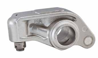
13 3.3 Rocker arm with insert element In rocker-arm valve trains the camshaft is positioned below the rocker arm at one of its ends. The cam stroke is transmitted to the lever either by means of sliding contact or by a roller (roller-type rocker arm). In order to minimize friction losses, modern rocker arms use needle bearing cam rollers. Either a hydraulic valve lash adjustment component (e.g. hydraulic insert element) or an adjusting screw for mechanical valve clearance adjustment are attached to the other end of the rocker arm. This part of the rocker arm operates the intake and/or exhaust valves. The point of contact between adjusting element (insert element) and valve must always be located at the end of the valve stem. Due to the reciprocation movements of the rocker arm, the contact surface between insert element and valve actuating element must be shaped in a slight curve (or spherical). This reduces the contact area and, consequently, the surface pressures applied to the valve stem end. In the event of excessive surface pressure, insert elements with contact pad are used. The contact pad is attached to the insert element using a ball/socket joint, thus ensuring even contact on the valve stem end. The contact surface is increased, thus reducing the contact pressure on the valve stem end. Rocker arm Hydraulic insert element Camshaft Valve Valve spring Characteristics of hydraulic insert elements Automatic valve lash adjustment Maintenance-free Very quiet Consistently low exhaust gas emissions throughout the entire service life Oil supply of the insert element is provided via the rocker arm shaft by oil feed holes leading from the rocker arm to the insert elements Hydraulic insert element without contact pad Characteristics Little installation space Low weight (low moving masses) Very cost-effective Hydraulic insert element with contact pad Characteristics Supported with a swivel facility on the insert element using a ball/socket joint Contact pad made from hardened steel Very low surface pressure in the valve contact area Rocker arm Characteristics The main body of the rocker arm is preferably made from aluminum. It accommodates: A needle bearing cam roller A hydraulic pivot element Rocker-arm valve trains operate at very low friction levels. In addition, they require little installation space, as all valves can be actuated by a single camshaft. Contact pad Main body Pivot element Cam roller 13
 The hydraulic pivot element is loaded by the engine valve spring force and inertia")

14 3 Design and operating principle of valve lash adjustment components 3.3 Rocker arm with insert element Hydraulic valve lash adjustment by means of rocker arm Sink-down phase (cam lift) The hydraulic pivot element is loaded by the engine valve spring force and inertia forces, as a result of which the distance between piston and housing is reduced. Small amounts of oil are forced from the high-pressure chamber through the leakage gap and are then returned to the oil reservoir via the oil collection groove and intake bore. At the end of the sink-down phase a small valve clearance is generated. Small amounts of oil-gas mixture are forced out through the ventilation hole and/ or leakage gap. B A 1 Oil Oil under engine oil pressure under high pressure 1 Cam roller 2 Oil channel 3 Support shim 4 Piston 5 Housing 6 Retaining cage (sheet metal or plastic) 7 Contact pad A Rocker arm B Insert element Adjustment phase (base circle) The return spring separates the piston from the housing until valve clearance is adjusted. The ball-type non-return valve opens as a result of the pressure differential between high-pressure chamber and oil reservoir. Oil flows from the reservoir via the ball-type non-return valve into the high-pressure chamber. The ball-type non-return valve closes and non-positive engagement in the valve train is re-established. B A 1 Oil under engine oil pressure 14
 mounted in the lever, act on two or three insert elements.")


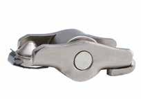
15 3.4 End pivot rocker arm with insert element End pivot rocker arm valve train In end pivot rocker arm valve trains, the camshaft is positioned above the valves and operates several lifters simultaneously using two cams which, by means of two rollers (roller-type end pivot rocker arm) mounted in the lever, act on two or three insert elements. The design with two insert elements is also referred to as dual end pivot rocker arm, with three insert elements as triple end pivot rocker arm. This type of valve train is typically used on multi-valve diesel engines. Although in this case the valves are mounted inversely, the system allows all valves to be operated by a single camshaft while leaving sufficient installation space to accommodate the injection nozzles. End pivot rocker arm characteristics The main body of the end pivot rocker arm is preferably made from aluminum. It accommodates: Needle bearing cam roller Hydraulic insert elements: One per valve Automatic valve lash adjustment Maintenance-free Very quiet Consistently low exhaust gas emissions throughout the entire service life It is also extremely speed-tolerant and minimizes friction loss. Triple end pivot rocker arm Main body Insert element Dual end pivot rocker arm Main body Insert element 15
 The hydraulic insert element is loaded by the valve spring")

16 3 Design and operating principle of valve lash adjustment components 3.4 End pivot rocker arm with insert element Hydraulic valve lash adjustment by means of end pivot rocker arm Cam lift phase (front view) The hydraulic insert element is loaded by the valve spring force and inertia forces, as a result of which the distance between piston and housing is reduced. Small amounts of oil are forced from the high-pressure chamber through the leakage gap and are then returned to the oil reservoir via the oil collection groove and intake bore. At the end of the sink-down phase small valve clearance is generated. Small amounts of oil-gas mixture are forced out through the ventilation hole and/or leakage gap A B Oil Oil under engine oil pressure under high pressure 1 Cam roller 2 Oil channel 3 Piston of the insert element 4 Housing of the insert element 5 Contact pad of the insert element A Triple end pivot rocker arm B Insert element Base circle phase (side view) The return spring separates the piston from the housing until valve clearance is adjusted. The ball-type non-return valve opens as a result of the pressure differential between high-pressure chamber and oil reservoir. Oil flows from the reservoir via the ball-type non-return valve into the high-pressure chamber. The ball-type non-return valve closes and non-positive engagement in the valve train is re-established. A Öl unter Motoröldruck B


 Improves dry-running properties in the")

17 3.5 OHV control system OHV control system In engines with a lower camshaft the distance between cam and lever is relatively large, requiring a pushrod to transmit the cam lift to the lever. Pushrods are used in combination with special types of cam followers and/ or valve lifters. The latter connect to the cam by means of sliding contact (flat-base or mushroom tappets) or by roller contact (roller-type tappets) and perform the task of guiding the pushrod. 1 Hydraulic roller tappet 2 Rocker arm 3 Cam roller 4 Housing 5 Piston 6 Anti-rotation element 7 Pushrod 8 Rocker arm bearing mounting 9 Needle bearing Hydraulic roller tappet Characteristics Designed with unique internal oil circulation system (labyrinth design) Improves dry-running properties in the event of insufficient pressure oil supply Automatically adjusts valve lash Maintenance-free Very quiet Consistently low exhaust gas emissions throughout the entire engine service life Rocker arm with rocker arm bearing mounting Characteristics Supplied as ready-to-fit lever/lever bearing unit Pivoted rocker arm mounting Rocker arm supported by needle roller bearing on rocker arm bearing mounting Low-friction motion Rocker arm Rocker arm bearing mounting 17


18 3 Design and operating principle of valve lash adjustment components 3.6 Switching valve lash adjustment components Since the beginning of the 20th century, engine designers and thermodynamics engineers have been searching for mechanisms to transmit variable lift curves to the valve the great number of filed patents gives evidence of this. Switching mechanical bucket tappet Pressure to meet strict exhaust emission and fuel consumption standards, and demands for increased driving comfort in terms of performance, torque and responsiveness call for more flexibility in the valve train. Today, volume production of variable valve timing systems, including cam followers such as rocker arms, finger followers or bucket tappets, is a reality. Variable valve timing is used to make different valve lift curves possible depending on the operating point, thus allowing for the optimal setting of the respective valve lift at all times. For each alternative valve lift such a system requires a corresponding cam to be the strokegiving element, except if the alternative is zero lift, meaning deactivation of the valve. The element engaged in the valve is supported at the base circle cam. Switching pivot element Cylinder or valve deactivation systems are predominantly used in high-capacity multi-cylinder engines (for example 8, 10 or 12 cylinders) aiming at reducing charge exchange losses (pump or throttle losses) and/or shifting the operating point. Due to the equidistant firing sequences, common V8 and V12 engine/transmission units can be switched to straight-four or straight-six engines. Tests on a stationary operating V8 engine have proved that the use of a cylinder deactivation system allows for fuel economy improvements between 8 % and 15 % during normal driving cycles. Valve deactivation is achieved by abandoning the second cam lobe driving the cam follower. Thus, the cam lift transmitting component is disconnected from the valve. The motion of the transmitting element is therefore idle, which is also referred to as lost motion. Since the connection to the valve spring is interrupted, the respective mass moments of inertia must be sustained by an additional spring, also called a lostmotion spring. The reciprocating movement continues to be performed by those parts of the valve train which are not deactivated. On the deactivated cylinders, the camshaft is only working against lost-motion spring forces, which are lower than the respective valve spring forces by a factor of 4 to 5. This minimizes friction losses. Switching roller tappet 18


 The pair of outer cams directs the outer lifter downward against the support spring.")
19 Operating principle of the switching bucket tappet Base circle phase (switching phase) The support spring pushes the outer lifter against the end stop of the inner lifter. The inner lifter touches the inner cam; a small clearance is generated between the outer cam and the outer lifter. At reduced engine oil pressure, the outer and inner lifters are linked via the spring-loaded locking piston. As the engine oil pressure exceeds the switching oil pressure, the locking piston is pushed back into the outer lifter by the operating piston. The hydraulic adjusting element positioned in the inner lifter adjusts valve clearance Cam lift phase, decoupled (zero or partial lift) The pair of outer cams directs the outer lifter downward against the support spring. The movement of the engine valve follows the outline of the inner cam. If all engine valves of a cylinder are deactivated (outer lifter decoupled), the cylinder will be deactivated, which allows for considerable fuel economies. 1 Outer cam 2 Inner cam 3 Operating piston 4 Locking piston 5 Inner lifter 6 Outer lifter 7 Support spring 8 Adjusting element 9 Support plate 10 Guiding groove 11 Anti-rotation device Throttled engine oil pressure Oil under engine oil pressure Oil under high pressure Cam lift phase, locked (full lift) The pair of outer cams directs the outer and inner lifters, which are coupled to each other, downward, and opens the engine valve. The hydraulic adjusting component is put under load. Small amounts of oil are forced from the highpressure chamber through the leakage gap. Having reached the base circle phase, valve clearance is set to zero. Decoupled Locked

 Cam lift phase, locked (full lift) 5 6 3 4 7 5")

 Decoupled (zero lift) Locked (full lift)")
20 3 Design and operating principle of valve lash adjustment components 3.6 Switching valve lash adjustment components Switching phases of a switching mechanical bucket tappet Base circle phase Cam lift phase, decoupled (partial lift) Cam lift phase, locked (full lift) Piston 2 Cam roller 3 Return spring 4 Locking piston 5 Inner lifter 6 Outer lifter 7 Support spring (lost motion spring) Switching pivot element Switching roller tappet Locked (full lift) Decoupled (zero lift) Locked (full lift) Decoupled (zero lift) 20


 Independent phasing of intake and exhaust camshaft (DOHC) Reduced")
21 4 Camshaft phasing systems 4 Camshaft phasing systems 4.1 General information The purpose of camshaft phasing systems is the variation of the gas exchange valve timing in an internal combustion engine. There are systems for variable intake and exhaust phasing, and also a combination of the two. By adjusting camshaft phasing, exhaust emissions and fuel consumption can be reduced. Typically, adjustment angles range from 20 to 30 at the camshaft and 40 to 60 at the crankshaft. Camshaft phasing systems are available for both the belt drive and the chain drive. And there are various compact design solutions to match individual installation space requirements. 4.2 Summary of camshaft phasing systems Each phasing concept has its benefits: Intake phasing Concept Advantages Reduced emissions Reduced fuel consumption Improved driving comfort (decreased idling speed) Optimized engine torque and output Gas exchange valve lift curves Exhaust phasing Reduced emissions Reduced fuel consumption Improved driving comfort (decreased idling speed) Independent phasing of intake and exhaust camshaft (DOHC) Reduced emissions Reduced fuel consumption Improved driving comfort (decreased idling speed) Optimized engine torque and output Synchronous phasing of intake and exhaust camshaft (DOHC/SOHC) Reduced emissions Reduced fuel consumption Unit in retarded timing position Unit in advanced timing position Unit in controlled position (with fixed adjustment angle) EO Exhaust open EC Exhaust closed IO Intake open IC Intake closed 21

22 4 Camshaft phasing systems 4.3 Camshaft phasing components and their operating principle Camshaft phasing unit Trigger disk and sensor, camshaft Solenoid valve Trigger disk and sensor, crankshaft Engine control unit Chamber connected to engine oil pressure Chamber decoupled/oil return Camshaft phasing control loop The camshaft is continuously adjusted in a closed control loop. The control system is driven by engine oil pressure. The desired adjustment angle of the inlet and exhaust valves, which depends on the load condition, temperature and engine rpm, is retrieved from a data map stored in the engine control unit. The engine control unit calculates the actual adjustment angle of the inlet and exhaust valves read by the sensors at the camshaft and crankshaft, and compares it against the desired angle. In the engine control unit the deviation of the actual angle from the desired angle is calculated constantly at high frequency. Advantages of the control loop: Deviation from the desired angle is almost immediately adjusted The desired angle is maintained with high angle precision If the actual angle differs from the desired angle, the power supply of the solenoid valve is modified such that oil from the engine oil circuit flows to the oil chamber in the phasing unit, increasing it in size, and oil from the oil chamber to reduce it in size goes back to the engine sump. 22 Depending on the oil volume flow, a more or less rapid rotation of the camshaft relative to the crankshaft is initiated, i.e. the shifting of the gas exchange valve timing to either advanced or retarded opening and closing position.

 on the camshaft (in the camshaft bearing area) are frequently used. Alternatively, oil can be fed to the camshaft via simple grooves in the plain bearing.")
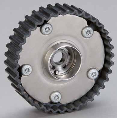
23 4.4 Camshaft phasing units There are currently two types of camshaft phasing units used in volume production: axial piston camshaft adjusters and vane-type camshaft adjusters. Axial piston camshaft adjuster Core components of an axial-piston camshaft adjuster Characteristics Axial piston camshaft adjusters are available for both chain-drive and belt-drive timing systems. Impellor Depending on the function and installation space requirements, the lines feeding the oil to the phasing unit chambers have different degrees of sealing ability: Seal rings (steel or plastic rings) on the camshaft (in the camshaft bearing area) are frequently used. Alternatively, oil can be fed to the camshaft via simple grooves in the plain bearing. Adjustment piston Drive hub The axial piston phasing unit is mounted on the camshaft by means of a central screw. Oil is delivered via the first camshaft bearing and the camshaft. Central screw This type of phasing unit is characterized by its robust design, minimized oil leakage and advanced control precision. 23


24 4 Camshaft phasing systems 4.4 Camshaft phasing units Axial piston camshaft adjuster Operating principle of an axial piston camshaft adjuster Depending on the requirements, applying current to the solenoid activates the hydraulic slider integrated into the hydraulic section of the solenoid valve to regulate the oil flow in one of the two oil chambers of the phasing unit. Impellor and drive hub are connected to each other in pairs by means of a helical spline. Axial displacement of the adjustment piston, which serves as linking element between the impellor and the drive hub, enables relative rotation between camshaft and crankshaft. Typical adjustment ranges are between 20 and 30 cam angle, and 40 and 60 crank angle. The adjustment piston, which holds a permanent angle position, is hydraulically locked in the controlled mode, with oil pressure being applied from both ends. 1 Impellor 2 Adjustment piston 3 Drive hub 4 Camshaft trigger disk 5 Seal ring 6 Solenoid valve, hydraulic section 7 Solenoid valve, solenoid 8 Hydraulic slider 9 Spring B Control position C Cam angle 4 5 A Basic position Chamber connected to engine oil pressure Chamber decoupled/oil return 24


25 Vane-Type camshaft adjuster Vane-type camshaft adjuster for the chain drive Characteristics Vane-type adjusters are available for both chain-drive and belt-drive timing systems. The stator is linked to the crankshaft via the timing drive, and the rotor is connected to the camshaft by means of the central screw. The rotor is radially mounted between two end stops in the stator. Typical adjustment ranges are between 20 and 30 cam angle, or 40 and 60 crank angle. The spring-supported slot-in vanes and the stator segments link up to form oil chamber pairs, which are fully filled with oil during operation. Chain drive Stator (impellor) 2 Rotor (drive hub) 3 Vane 4 Locking device Vane-type camshaft adjuster for the belt drive Belt drive Characteristics Torque transmission from the stator to the rotor is ensured via the hydraulically locked vanes. The typical amount of vanes is 3-5, depending on the required adjusting time and the overall load applied to the system. The locking device provides a secure mechanical connection between the drive and output during engine start-up. It is hydraulically released as soon as the phasing unit starts to move from its basic position


26 4 Camshaft phasing systems 4.4 Camshaft phasing units Distinctions between Camshaft Phasing Units in the chain drive and belt drive Chain drive phasing unit Chain drive Camshaft phasing units in the belt drive must provide absolute oil-tightness. This is not required for chain drive camshaft units, as the chain drive itself is protected by a cover. Belt drive phasing unit Belt drive Sealing of the belt drive phasing unit is ensured by seal elements in the adjuster, by the rear cover which serves as contact surface to the shaft seal ring, and by the front protective cover which seals the adjuster towards the front after the central screw is fixed. 26


27 Distinctions between Intake and exhaust phasing Intake phasing by means of a vane-type camshaft adjuster in the chain drive Adjuster in basic position A Valve timing is in retarded position. The locking device is engaged. At the same time, oil in the oil chamber puts the vanes under single-sided pressure, thereby keeping them at the end stop. The solenoid valve is not energized. Adjuster in controlled mode B Current is applied to the solenoid valve. Oil flows into the second chamber A. The oil unlocks the locking element and turns the rotor. This shifts the camshaft to advanced position. To arrest the phasing unit in an intermediate position the solenoid valve is switched to control position. The oil chambers are then almost completely closed, compensating only for oil leakage. B Control position Stator 2 Rotor 3 Vane 4 Locking device 5 and 6 Oil chambers 7 Oil pump 8 Return Chamber connected to engine oil pressure Chamber decoupled/oil return A Basic position


28 4 Camshaft phasing systems 4.4 Camshaft phasing units Distinctions between Intake and exhaust phasing Exhaust phasing by means of vane-type camshaft adjuster in the belt drive Adjuster in basic position A Valve timing is in advanced or retarded position. The locking device is engaged. The dragging friction at the camshaft has a decelerating impact towards the retarded position. The spiral-coiled spring moment is higher than the friction moment of the camshaft. The spiral-coiled spring is attached to the cover and connected in the center to the rotor by means of a support sheet as part of the central screw clamp-type joint. Adjuster in controlled mode B Current is applied to the solenoid valve. Oil flows into the second chamber. The oil unlocks the locking element and turns the rotor. This moves the camshaft to retarded position. B Control position Stator 2 Rotor 3 Seal elements 4 Rear cover 5 Shaft seal ring 6 Front protective cover 7 Spring 8 Cover 9 Support sheet 10 Oil pump 11 Return 12 and 13 Oil chambers Chamber connected to engine oil pressure Chamber decoupled/ oil return A Basic position
 and the position of the seal between wet hydraulic section and dry plug-in section are flexibly")

29 4.5 Solenoid valve Plug-In valve Core components of a plug-in valve Characteristics The valve is compact but of a modular design and permits modification to match the particular application. The position and type of the plug and the bolting flange, the type of oil feed (lateral or end face) and the position of the seal between wet hydraulic section and dry plug-in section are flexibly selectable. There are two variants of plug-in solenoid valves: Integrated directly into the cylinder head Connected via an intermediate housing The valve is electrically connected to the engine control unit. The hydraulic slider is located in a bore providing connection to the oil feed, working chambers of the camshaft phasing unit and the oil return. The control slider is axially loaded by spring force in the basic position, and directed against this spring force when current flows through the solenoid: Oil flow to and from both chambers varies In control position the oil flow is practically interrupted, so that the rotor is stiffly locked in the camshaft phasing unit Hydraulic section Solenoid The control valve is a proportional valve with four connections, with one connection each to the: Oil pump P Return T Working chamber A of the camshaft phasing unit Working chamber B of the camshaft phasing unit 29

30 4 Camshaft phasing systems 4.5 Solenoid valve Plug-In valve Operating principle of a plug-in valve When current is applied to the solenoid, this directs the internal control slider against a spring force in the hydraulic section and thus switches the oil pressure between the working chambers I and II. The working chamber, which is decoupled from oil pressure after a predetermined period of time, is connected to the return. In order to fix a timing position, the valve is held in the central position, where it is almost entirely decoupled from all connections. 1 Solenoid 2 Control slider 3 Oil chamber inlet 4 Return T 5 Engine control unit 6 Connection to the crankshaft sensor 7 Connection to the camshaft sensor 8 Oil pump B Control position 1 2 II I C Cam angle A Basic position 8 5 I II 3 Chamber connected to engine oil pressure Chamber decoupled/oil return 30
.")
31 Central valve Core components of a central valve Characteristics The separate central magnet is coaxially positioned in front of the central valve. The central valve is screwed into the camshaft. The camshaft phasing unit is solidly connected to the camshaft (by welding). Short oil flow distances between central valve and camshaft phasing unit allow for reduced oil pressure loss and high adjustment velocity. Operating principle When current is applied to the coaxially mounted electromagnet, this directs the internal control slider against a spring force in the hydraulic section and thus switches the oil pressure between the working chambers. The working chamber, which is decoupled from oil pressure after a predetermined period of time, is connected to the return. In order to fix a timing position, the valve is held in a central position, where it is almost entirely decoupled from all connections. Hydraulic section Solenoid The central valve is a proportional valve with five connections, with one connection each to the: Oil pump P Return T (2x) Working chamber A of the camshaft phasing unit Working chamber B of the camshaft phasing unit 31


32 5 Maintenance and service 5 Maintenance and service Important: To avoid malfunction resulting from contamination with foreign matter, CLEANLINESS is imperative! Even the slightest contamination can impair the functioning of the components and eventually cause total engine failure! Make sure the parts are installed correctly (mount recess on ball head and valve contact surface on valve stem). Ensure that the rocker arm is in the correct mounting position (offset). This varies according to the individual design. Hydraulic valve lash adjustment components must not be disassembled, to avoid impairment of the high-precision mechanism. Only engine oils authorized by the manufacturer must be used. 5.1 Replacement of mechanical bucket tappets During initial assembly, manufacturing tolerances between cam base circle and valve seating are adjusted using adjusting shims of different thicknesses. Important: With the correct setting there is still a defined basic clearance between base cam circle and adjusting shim. This basic clearance serves to compensate for length differences in the valve train as a result of: Thermal expansion Compression set Wear and tear Mechanical bucket tappet with top adjusting shim If the setting dimensions differ from the manufacturer s specifications (excessive or insufficient valve clearance), the adjusting shim has to be replaced (removal of the camshaft is not necessary!). Mechanical bucket tappet with bottom adjusting shim If the setting dimensions differ from the manufacturer s specifications (excessive or insufficient valve clearance), the adjusting shim and the bucket have to be replaced (in this case, removal of the camshaft is required!). Mechanical bucket tappet with graded bottom thickness If the setting dimensions differ from the manufacturer s specifications (excessive or insufficient valve clearance), the bucket has to be replaced (in this case, removal of the camshaft is required!). 32


33 5.2 Replacement of hydraulic bucket tappets Important: When replacing hydraulic components, the manufacturer s specifications must be followed at all times. The methods described in this section generally apply to all types of bucket tappets. All hydraulic bucket tappets are different! Even if some types look identical from the outside, they differ significantly on the inside. So remember that hydraulic bucket tappets are not automatically interchangeable. The reasons are: Different sink-down times of the hydraulic element Different oil consumption Different oil specifications Different finishing of the cup bottom (e.g. case hardened or nitrated) Different oil pressure Different tappet design (labyrinth-type, with anti-drain protection or with internal return) Different spring forces of the non-return valve Different valve lift (in mm) 5.3 Replacement of finger followers with hydraulic pivot element In order to avoid repeated repairs and subsequent additional costs for the customer, it is strongly recommended to replace the complete finger follower set. If a new pivot element is mounted on a used finger follower, the head of the pivot element will not fit properly in the recess of the finger follower, which causes excessive wear and premature failure. Important: The most important difference between the various hydraulic pivot elements is in their sink-down time. Matching the wrong hydraulic pivot element and finger follower can entail serious malfunction in the valve train even complete engine failure. 33
34 5 Maintenance and service 5.4 Replacement of rocker arms with hydraulic insert element Defective rocker arms must always be replaced together with the hydraulic insert element! The reasons are: The fit size of the mounting bore for the rocker arm precisely matches the outer diameter of the hydraulic insert element (toleranced dimensions). To extract the hydraulic insert element from the rocker arm, force must be applied by a tool (e.g. pliers), which causes pinching, and thus damage, to the locating bore of the hydraulic insert element. If the oil feed holes and channels are clogged with old oil deposits, the oil supply of the hydraulic insert elements is no longer guaranteed. The cam roller (needle bearing) of the rocker arm is subjected to constant wear generated at the contact surface of the cam lobe. Important: The most important difference between the various hydraulic pivot elements is in their sink-down time. Matching the wrong hydraulic insert element and rocker arm can lead to total engine breakdown. 5.5 General repair and maintenance guidelines Note: These general guidelines must be observed when repair or maintenance work is being performed on the valve train. Adhere to the manufacturer s specifications at all times. Replacement every 120,000 km When overhauling engines with more than 120,000 driven kilometers, be sure to replace the hydraulic valve lash adjustment components. Due to the narrow system tolerances, hydraulic components have then generally reached or even exceeded their wear limit. Always replace in a set If one or more hydraulic valve lash adjustment component(s) is damaged, the whole set of components should be replaced. If only single components are replaced, the valve lift may not be equal for all parts due to different amounts of oil released through the leakage gap. This may result in faulty valve closure, and eventually in a burnt valve seating. In order to avoid repeated repairs and subsequent additional costs for the customer, we strongly recommend replacing the complete finger follower set. New camshaft new hydraulic bucket tappet When replacing hydraulic bucket tappets, the camshaft must always be replaced as well and vice versa. Due to the wear pattern on the bucket tappet bottom and cam track, matching new and worn parts will result in short service life of the components. Choice of hydraulic components The main criteria for the choice of a suitable hydraulic component must be actual assembly length (may differ from overall length of the hydraulic element), outer diameter as well as dimension and arrangement of the oil grooves. Always only use the hydraulic elements included in parts lists and catalogs. Please be sure to never install standard-size hydraulic bucket tappets in over-sized bores of the cylinder head. 34

35 Filling of hydraulic components Some manufacturers offer valve lash adjustment components for the aftermarket, which are already prefilled with the required amount of oil or contain at least an amount sufficient for the running-in phase. Partly filled valve lash adjustment components ensure that the hydraulic piston is automatically in the right position during start-up of the overhauled engine. In this short period of time the hydraulic elements auto-air bleed, unlike initially filled components, emitting a ticking noise in the cylinder head area until the part is filled to the required oil level by the engine oil circuit. Since hydraulic elements are shipped in transport position, they do not settle to their individual installation position until they have been mounted and loaded in the camshaft. Do not rotate the camshaft during this period. The sinkdown phase normally requires 2-10 minutes at ambient temperature, after which the camshaft can be rotated and the engine started. General fitting instructions Drain the engine oil Purify the oil system, in particular the oil channels leading to the hydraulic components, disassemble and purify the engine sump and oil screen, if necessary Mount a new oil filter Check the oil level and oil supply Assemble the cylinder head Wait for the hydraulic components to sink down before rotating the camshaft and starting the engine 5.6 Air bleeding of hydraulic valve lash adjustment components recommendations Valve train noise can occur under certain operating conditions (multiple start-ups, cold start, engine initial assembly). Observe the following instructions to ensure rapid bleeding of the high-pressure chamber and reservoir of the hydraulic element: Keep the engine running at a constant speed of approx. 2,500 rpm or at variable speeds in the 2,000 to 3,000 rpm range for at least 4 minutes. Then keep the engine idling for approx. 30 seconds. The system is bled if no more noise is audible. If valve train noise persists, repeat steps 1 and 2. In 90 % of cases, valve train noise is eliminated after the first air bleeding cycle. In very few cases, it may be necessary to repeat the procedure up to 5 or 6 times. If valve train noise is still perceptible after the fifth bleeding cycle, it is recommend to replace the relevant parts and perform additional tests. 35


36 5 Maintenance and service 5.7 Replacement of camshaft phasing units recommendations Timing pin Some types of camshaft phasing units are equipped with a timing pin. When installing these, ensure that the pin is precisely aligned to the hole in the camshaft to prevent tilting of the phasing unit. Failure to do so results in malfunction and inaccurate guiding of the belt or chain. Camshaft seal When replacing the camshaft phasing unit, it is also strongly recommended to replace the camshaft seal which protects the connection between camshaft and cylinder head. Central screw Screw plug Central screw When replacing the camshaft phasing unit, the central screw, which connects the phasing unit to the camshaft, should also be replaced, as the screw is plastically deformed when the specified tightening torque is applied, which varies depending on the vehicle manufacturer and must be observed at all times. Therefore, re-using the screw is not advisable. Screw plug When replacing the camshaft phasing unit, it is also recommended to replace the screw plug, which seals the phasing unit towards the outside. It is fitted with a seal ring, which may be damaged by unscrewing. 36
37 6 Failure diagnosis and damage assessment 6 Failure diagnosis and damage assessment 6.1 General information on damage assessment Under mixed friction conditions abrasive and adhesive wear occurs between metallic friction partners. Both types of wear including fatigue wear, which leads to pitting formation at the surface, often result in the total failure of the friction partners. Wear can also be the result of different kinds of corrosion. Abrasion generally describes rubbing or scraping processes. Adhesion occurs where main body and counter body are in direct contact with each other. Several parameters can influence wear: Materials (combination of materials, heat treatment, coating) Contact geometries (macro/micro geometries, molding accuracy, roughness, percentage contact area) Load (forces, moments, Hertzian pressure) Kinematic parameters (relative velocity, hydrodynamic velocity, surface pressure) Lubrication (oil, viscosity, amount, additivity, contamination, ageing) Noise emission during warm-up phase Noise emission caused by inflation Possible causes: Defective, fatigued or wrong valve spring (wrong parts mounted together) Defective valve guide or valve stem Engine overrev As a result of this the valve train components are separated at the contact surfaces, which in turn generates disproportionate piston lift. Consequently, only an insufficient amount of oil can be displaced in this short period of time. Result: The valve does not close properly, causing performance loss and even burning of the valve. In addition, valves hitting the piston crown can cause severe engine damage. Owing to the narrow system tolerances, valve lash adjustment components are very sensitive to engine oil contamination. In addition, dirt particles do not only lead to increased wear of the moving parts, but also cause ticking noise in hydraulic valve lash adjustment components. In the majority of cases, noise during engine warm-up is not grounds for complaint. When the engine is turned off, some valves can remain in the opened position where valve spring force is applied to adjust valve lash. As a result, oil is forced out of the high-pressure chamber, which is then gradually refilled during engine warm-up. The air cushion generated in the open hydraulic element is being compressed, which is the source of the ticking noise. Noise emitted by warm engine Frequently, the root cause of noise emitted by a warm engine is insufficient oil supply. Possible causes are: Hydraulic piston seized resulting from oil contamination Oil foaming caused by engine oil level being too high or too low Leakage on the oil pump intake side Insufficient oil pressure due to oil line leak 37


38 6 Failure diagnosis and damage assessment 6.2 Residual dirt Aluminum residues from cylinder head machining Large quantities of residual dirt particles are frequently found when examining returned defective parts. These foreign particles, e.g. aluminum, result from cylinder head machining. Combustion deposits in diesel engines Lint from cleaning cloths or combustion deposits from diesel engines may be found in the engine oil. 6.3 Failure diagnosis of valve train components 38 Important: When examining and assessing damage to hydraulic components, the manufacturer s instructions must be observed at all times. The methods described in this section generally apply to all types of valves. Visual examination Always replace hydraulic components showing external damage, such as scoring, scratching or seizing marks. Also examine the mating surface in the valve train. Pay particular attention to the bucket tappet bottom. Its contact surface is the highest-loaded area in the engine. In new condition, the phosphated crown of VW tappets is spherical. The coating wears off during the break-in period. The criterion for damage assessment on a bucket tappet is therefore not the pattern on the coating, but the outline of the tappet crown. If the contact surface has become concave, the bucket tappets and the camshaft have to be replaced. Manual examination A simple yet effective examination method of hydraulic valve lash adjustment components under workshop conditions is their ability to be compressed. A filled component should be difficult to compress by hand. This test must be performed with great caution, so as not to press oil out of the leakage gap. If the filled element can be compressed quickly without applying much force, it must be replaced. Thorough function tests of hydraulic elements are only possible using extensive testing procedures, including, for example, measurement of the sink-down time, which can only be carried out at the manufacturer s facilities.


39 Damage assessment bucket tappets Wear to the bucket crown Normal wear and tear Normal running surface profile of a bucket tappet. The circular marks are caused by the rotation of the tappet and are not grounds for complaint. Remedy No remedial measure required the surface is in good working condition. Increased wear Heavily worn bucket crown. Such a running surface profile implies heavy abrasion of the bucket tappet crown. Remedy Bucket tappet and camshaft must be replaced. Heavy wear Adhesive-abrasive wear causing complete failure. Remedy The bucket tappet must be replaced. Additionally, thorough inspection of the camshaft position is required. Scoring on the bucket tappet housing and guiding bore Cause Engine oil contaminated by excessive residual dirt. Bucket tappet Guiding bore Result Bucket tappet seized in the locating bore. Remedy Clean (scavenge) the engine. Pay attention to cleanliness when installing the new bucket tappet. 39


40 6 Failure diagnosis and damage assessment 6.3 Failure diagnosis of valve train components Damage assessment finger followers Wear to the finger follower and pivot element Note: Direction of view in the figures 1 to 4. Normal wear and tear Smoothing marks in the contact area of the rocker arm recess. Normal wear and tear as occurring during operation. Smoothing marks in the contact area of the ball head. Remedy No remedial measure required the surface is in good working condition. 1 2 Increased wear Critical degree of highly abrasive wear of the ball head resulting in distorted ball head geometries. Critical degree of highly abrasive wear of the recess resulting in distorted recess geometries. Remedy The hydraulic pivot element and its finger follower must be replaced


41 Wear to the valve contact face of the finger follower Note: Direction of view in the figures 1 to 4. Normal wear and tear Minor smoothing marks on the valve contact face resulting from the relative movement between finger follower and valve. Normal wear and tear as occurring during operation. Remedy No remedial measure required the surface is in good working condition. 1 Heavy wear Highly abrasive wear of the valve contact face. Clearly visible edges at the outer contact face imply that wear depth is several tenths of a millimeter. Continued operation involves the risk of lever fracture. Remedy The hydraulic pivot element and its finger follower must be replaced. The valve stem must be checked. 2 Wear of the outer ring of the cam roller Normal wear and tear Outer diameter of the cam roller is not visibly damaged. The circular marks result from minute foreign particles trapped between cam roller and cam. Normal wear and tear as occurring during operation. Remedy No remedial measure required the surface is in good working condition. 3 Heavy wear Heavy wear of the outer diameter of the cam roller including significantly deformed geometries of the cam roller. Remedy The hydraulic pivot element and its finger follower must be replaced. The position of the relevant camshaft must be checked. 4 41


42 6 Failure diagnosis and damage assessment 6.3 Failure diagnosis of valve train components Damage assessment finger followers Wear to the finger follower roller shaft Examination of the radial play of the roller bolt To check the radial play the rocker is simply moved up and down in a radial direction. If the radial play is several tenths of a millimeter, the load zone of the roller shaft is worn and the part must be replaced. Heavy wear The load zone of the roller shaft is heavily worn. Final stage of wear: The needles in the roller shaft have become loose. Remedy The hydraulic pivot element and its finger follower must be replaced. Improper functioning of the pivot element Non-return valve of the pivot element Cause Contamination with foreign particles washed into the valve lash adjustment component by engine oil. Result Improper functioning of the non-return valve. 42 Caution! The manufacturer s warranty expires if the parts are disassembled at the garage during the warranty period. In order to ensure proper functioning of the high-precision adjustment mechanism of hydraulic pivot elements, parts which have been disassembled must not be re-installed as this is detrimental to the system s overall operational reliability.
 the engine and change oil. Replace phasing unit.")

43 Damage assessment camshaft phasing Rattling noise in the phasing unit area at engine start-up Cause Excessive locking play. Remedy The phasing unit needs to be replaced. Limited or no function of the phasing unit. Cause Oil sludge build-up or oil contamination. Remedy Clean (scavenge) the engine and change oil. Replace phasing unit. Solenoid valve for camshaft phasing Solenoid valve does not work Cause Dirt particles in the engine oil impair the function of the control valve piston, the piston is seized. Intermittent contact at the control valve electrical connection. Remedy The solenoid valve needs to be replaced. The electrical connection must be examined and repaired, if necessary. Note: If the solenoid valve piston does not reach the required end positions, the engine control unit generates a corresponding error message ( Failure to reach desired angle ). 43
Valve lash adjustment elements. Product Information
 Valve lash adjustment elements Product Information Valve lash adjustment elements Foreword Modern engines nowadays have to satisfy far greater demands than even just 10 years ago. One of the main reasons
Self-Adjusting Clutch (SAC) Technology Special tools / User instructions
 Technology Special tools / User instructions") Self-Adjusting Clutch (SAC) Technology Special tools / User instructions The content of this brochure shall not be legally binding and is for information purposes only. To the extent legally permissible,
Self-Adjusting Clutch (SAC) Technology Special tools / User instructions The content of this brochure shall not be legally binding and is for information purposes only. To the extent legally permissible,
ENGINE MECHANICAL <134>
 11A-1 GROUP 11A ENGINE MECHANICAL CONTENTS GENERAL INFORMATION........ 11A-2.................. 11A-3 11A-2 The newly developed 1.1L 134910 engine features 3-cylinder, 12-valve, and double overhead
Variable Valve Timing
 Service. Self-study programme 246 Variable Valve Timing with fluted variator Design and Function The demands on combustion engines continue to grow. On one hand, customers want more power and torque, while
Modern Auto Tech Study Guide Chapters 13 & 14 Pages Engine Construction 52 Points
 Modern Auto Tech Study Guide Chapters 13 & 14 Pages 182-216 Engine Construction 52 Points Automotive Service 1. The engine top end includes the cylinder, valve cover and intake & exhaust. Head, Manifolds
FAG Wheel Bearing Repair Solution for Light Commercial Vehicles
 FAG Wheel Bearing Repair Solution for Light Commercial Vehicles Mercedes-Benz Sprinter, Viano, Vito and Volkswagen Crafter Front Axle The content of this brochure shall not be legally binding and is for
Precision Degree Wheel Kit
 555-81621 Precision Degree Wheel Kit Instruction Booklet Instructions for 81621 Camshaft Degree Kit Thank you for purchasing the Jegs Camshaft Degree Kit. Please follow these detailed instructions to properly
The D series CONTENTS. the single-cylinder diesel engine with revolutionary technology 4. -SILENT PACK environmentally friendly perspectives 5
 D series The D series CONTENTS the single-cylinder diesel engine with revolutionary technology 4 -SILENT PACK environmentally friendly perspectives 5 Engine data, installation data 6 Power output, torque,
Tips & Technology For Bosch business partners
 Tips & Technology For Bosch business partners Current topics for successful workshops No. 02 Trucks High-pressure pumps in the common rail system for commercial vehicles Requirements and tasks The high-pressure
three different ways, so it is important to be aware of how flow is to be specified
 Flow-control valves Flow-control valves include simple s to sophisticated closed-loop electrohydraulic valves that automatically adjust to variations in pressure and temperature. The purpose of flow control
SPECIFICATIONS TEST AND ADJUSTMENT SPECIFICATIONS SPECIFICATIONS ENGINE FD620D, K SERIES
 ENGINE FD620D, K SERIES SPECIFICATIONS SPECIFICATIONS TEST AND ADJUSTMENT SPECIFICATIONS Engine Oil Pressure Sensor Activates............................... 98 kpa (14.2 psi) Oil Pressure While Cranking
Failure Diagnosis. The LuK guide to troubleshooting clutch system failures and malfunctions on agricultural vehicles
 Failure Diagnosis The LuK guide to troubleshooting clutch system failures and malfunctions on agricultural vehicles Contents Page Failure diagnosis / causes of failures Clutch fault diagnosis What is clutch
ENGINE & WORKING PRINCIPLES
 ENGINE & WORKING PRINCIPLES A heat engine is a machine, which converts heat energy into mechanical energy. The combustion of fuel such as coal, petrol, diesel generates heat. This heat is supplied to a
The Life of a Lifter, Part 2
 Basics Series: The Life of a Lifter, Part 2 -Greg McConiga Last time we looked at some complicated dynamics and compared flats to rollers. Now for the hands-on. 6 FEATURE This off-the-shelf hydraulic lifter
AGN 076 Alternator Bearings
 Application Guidance Notes: Technical Information from Cummins Generator Technologies AGN 076 Alternator Bearings BEARING TYPES In the design of STAMFORD and AvK alternators, the expected types of rotor
SECTION 6A1-2 - ENGINE MECHANICAL - V6 SUPERCHARGED
 SECTION 6A1-2 - ENGINE MECHANICAL - V6 SUPERCHARGED CAUTION: This vehicle will be equipped with a Supplemental Restraint System (SRS). A SRS will consist of either seat belt pre-tensioners and a driver
SPECIFICATIONS TEST AND ADJUSTMENT SPECIFICATIONS SPECIFICATIONS ENGINE FD620D, K SERIES
 TEST AND ADJUSTMENT Engine Oil Pressure Sensor Activates............................... 98 kpa (14.2 psi) Oil Pressure While Cranking (Minimum).......................... 28 kpa (4 psi) Oil Pressure.....................................
LuK Repair Solution for manual transmissions. Disassembly and assembly Special tool/failure diagnosis VW 02J
 LuK Repair Solution for manual transmissions Disassembly and assembly Special tool/failure diagnosis VW 02J The content of this brochure shall not be legally binding and is for information purposes only.
Installation Procedures
 For the precision ball and roller bearings supplied by MRC Bearings, skill and cleanliness while handling, mounting and dismounting are necessary to ensure satisfactory bearing performance. As precision
RACK JACK. Synchronous Lifting Systems
 RACK JACK Synchronous Lifting Systems RACK JACK (ROUND RACK TYPE) Operation The Rack Jack from WMH Herion provides simple synchronous lifting motion. The system of rack and pinion transforms linear motion
VALVE TIMING DIAGRAM FOR SI ENGINE VALVE TIMING DIAGRAM FOR CI ENGINE
 VALVE TIMING DIAGRAM FOR SI ENGINE VALVE TIMING DIAGRAM FOR CI ENGINE Page 1 of 13 EFFECT OF VALVE TIMING DIAGRAM ON VOLUMETRIC EFFICIENCY: Qu. 1:Why Inlet valve is closed after the Bottom Dead Centre
ENGINE MECHANICAL <2.0L ENIGNE>
 11A-1 GROUP 11A ENGINE MECHANICAL CONTENTS GENERAL DESCRIPTION......... 11A-2.................. 11A-3 11A-2 This model is equipped with a newly developed 4B11 engine. It is a 4-cylinder,
Sensor-Bearing Units Steer-By-Wire Modules Mast Height Control units Other sensorized units
 Mechatronics Sensor-Bearing Units... 957 Steer-By-Wire Modules... 967 Mast Height Control units... 969 Other sensorized units... 971 955 Sensor-Bearing Units SKF Sensor-Bearing Units... 958 SKF Explorer
TRANSLATION (OR LINEAR)
") 5) Load Bearing Mechanisms Load bearing mechanisms are the structural backbone of any linear / rotary motion system, and are a critical consideration. This section will introduce most of the more common
5) Load Bearing Mechanisms Load bearing mechanisms are the structural backbone of any linear / rotary motion system, and are a critical consideration. This section will introduce most of the more common
Chapter 6. Supercharging
 SHROFF S. R. ROTARY INSTITUTE OF CHEMICAL TECHNOLOGY (SRICT) DEPARTMENT OF MECHANICAL ENGINEERING. Chapter 6. Supercharging Subject: Internal Combustion Engine 1 Outline Chapter 6. Supercharging 6.1 Need
Hi-Tech & Pro Magnum Roller Rocker Arms
 Hi-Tech & Pro Magnum Roller Rocker Arms Thank you for choosing COMP Cams products; we are proud to be your manufacturer of choice. Please read this complete instruction sheet carefully (including the application
Vickers 45. VMQ Series 30 Vane Pumps. Fixed Displacement, For Industrial and Mobile Applications (4.188)
") [ (4.188) 49,4 (1.94) /21,8 /.86) 174,7/172,3 (6.88/6.78) 332,9/33,5 (13.11/13.1) "M" is marked if metric port threads No marking if inch port threads AS-568-152 O-ring Vickers 45 65,3 (2.57) 13 (5.1 VMQ
[ (4.188) 49,4 (1.94) /21,8 /.86) 174,7/172,3 (6.88/6.78) 332,9/33,5 (13.11/13.1) "M" is marked if metric port threads No marking if inch port threads AS-568-152 O-ring Vickers 45 65,3 (2.57) 13 (5.1 VMQ
Shaft Couplings Flange-Couplings Rigid Shaft Couplings Flexible Couplings
 Shaft Couplings Flange-Couplings Rigid Shaft Couplings Flexible Couplings 44 Edition 2013/2014 RINGSPANN Registered Trademark of RINGSPANN GmbH, Bad Homburg 2 Table of Contents Flange-Couplings Page Flange-Couplings
Introducing the Sea-Doo 4-TEC SUPERCHARGED
 Introducing the Sea-Doo 4-TEC SUPERCHARGED 185HP & MASSIVE TORQUE iame41-1.doc 29Mar03 Page 1 of 2 Another Sea-Doo watercraft first and only. Introducing the 185hp, GTX 4-TEC SUPERCHARGED PWC. The 4-TEC
FTE automotive Innovation drives. Transmission actuation. hydraulic and electromechanical components for automatic transmissions
 FTE automotive Innovation drives Transmission actuation hydraulic and electromechanical components for automatic transmissions 1 Innovative elements for the current development trend Transmission actuators
Variable Valve Drive From the Concept to Series Approval
 Variable Valve Drive From the Concept to Series Approval New vehicles are subject to ever more stringent limits in consumption cycles and emissions. At the same time, requirements in terms of engine performance,
Tips & Technology For Bosch business partners
 Tips & Technology For Bosch business partners Current topics for successful workshops No. 05 Trucks Starters and starter systems Part 2 Moderately heavy commercial vehicles with diesel engines having a
Our products for water transmission Double-eccentric butterfly valves Air valves Non-return valves Connection systems
 Water transmission Lengths of over 100 kilometres and nominal widths of over DN 100 are not unusual for large scale water transmission systems. Often they are installed as parallel pipelines. They ensure
Breakthrough in Linear Generator design
 Breakthrough in Linear Generator design Rotary Linear Generator (stroke-rotor generator) By Physicist Wolfhart Willimczik ABSTRACT The law of inductions demands high speed for the moveable electrical parts,
Starting up hydraulic systems
 General / Installation A hydraulic system that operates economically, safely, and trouble-free requires careful planning, as well as proper installation and start-up. Conscientious maintenance has a considerable
UNIT 2 POWER PLANTS 2.1 INTRODUCTION 2.2 CLASSIFICATION OF IC ENGINES. Objectives. Structure. 2.1 Introduction
 UNIT 2 POWER PLANTS Power Plants Structure 2.1 Introduction Objectives 2.2 Classification of IC Engines 2.3 Four Stroke Engines versus Two Stroke Engines 2.4 Working of Four Stroke Petrol Engine 2.5 Working
Handout Activity: HA170
 Basic diesel engine components Handout Activity: HA170 HA170-2 Basic diesel engine components Diesel engine parts are usually heavier or more rugged than those of similar output gasoline engines. Their
Design specifications
 Design specifications Design To relevant standards: IEC, VDE, DIN, ISO, EN With squirrel-cage or slipring rotor Degree of protection IP 55 / IP 65 Cooling method IC511, suitable for both indoor and outdoor
SECTION 4A BRAKE SYSTEM TABLE OF CONTENTS
 SECTION 4A BRAKE SYSTEM TABLE OF CONTENTS Description and Operation... 4A-2 Braking System Testing... 4A-2 Hydraulic Brake System... 4A-2 Brake Pedal... 4A-2 Master Cylinder... 4A-2 Brake Booster... 4A-3
3. BEARING ARRANGEMENT DESIGN
 3. BEARING ARRANGEMENT DESIGN 3.1 GENERAL PRINCIPLES OF ROLLING BEARING ARRANGEMENT DESIGN Rotating shaft or another component arranged in rolling bearings is guided by them in radial as well as in axial
GSG Diffuser Style Barrel Pump ISO (API 610) Type BB5
 Type BB5") GSG Diffuser Style Barrel Pump ISO 13709 (API 610) Type BB5 Sulzer Sulzer is a world leader in reliable products and innovative pumping solutions. Our advanced research and development, detailed process
GSG Diffuser Style Barrel Pump ISO 13709 (API 610) Type BB5 Sulzer Sulzer is a world leader in reliable products and innovative pumping solutions. Our advanced research and development, detailed process
Gerotor pump, fixed displacement volume
 Gerotor pump, fixed displacement volume RE 10545/12.11 1/12 Type GZ Component series 1X Maximum operating pressure 15 bar Maximum displacement 140 cm³ H7572_d Table of contents Contents age eatures 1 Ordering
NZQA unit standard version 5 Page 1 of 6. Demonstrate knowledge of engine design factors and machining practices
 Page 1 of 6 Title Demonstrate knowledge of engine design factors and machining practices Level 4 Credits 20 Purpose People credited with this unit standard are able to demonstrate knowledge of engine design
Oregon Fuel Injection
 2001 2006 Dodge Mercedes - Freightliner Sprinter Diagnostics In order to do proper diagnostics you will need a scan tool and some special tools available from Mopar Special Tools http://mopar.snapon.com.
Heavy Duty Ball Screw Linear Actuators
 Heavy Duty Ball Screw Linear Actuators Thrust From 2,000 to 25,000 lbf Heavy Wall Steel Construction Longest Life Simultaneous High Thrust with High Speed Piston with Rugged Anti Rotation Feature Sealed
 Page 1 of 9 303-01C Engine 6.0L Diesel 2004 F-Super Duty 250-550/Excursion DESCRIPTION AND OPERATION Procedure revision date: 08/06/2003 Engine Printable View Engine Description The 6.0L diesel engine
INSTALLATION, OPERATION AND MAINTENANCE INSTRUCTIONS
 INSTALLATION, OPERATION AND MAINTENANCE INSTRUCTIONS Contents Section 1. General Observations... 2 2. Operation... 4 3. Control During Operation... 5 4. Trouble Shooting... 6 5. Maintenance... 7 Please
SAMPLE STUDY MATERIAL
 IC Engine - ME GATE, IES, PSU 1 SAMPLE STUDY MATERIAL Mechanical Engineering ME Postal Correspondence Course Internal Combustion Engine GATE, IES & PSUs IC Engine - ME GATE, IES, PSU 2 C O N T E N T 1.
NUMBER: S.M. REF.: Refer to 2.5 ENGINE: 60 DATE: January 2007
 NUMBER: 1 60 07 S.M. REF.: Refer to 2.5 ENGINE: 60 DATE: January 2007 SUBJECT: N3 ELECTRONIC INJECTOR PUBLICATION: 6SE483 The Series 60 Service Manual has been revised. Engine models built from December
PRESSRELEASE. Technical Information. Optimization focus: Engine mechanics. Less friction in the engine reduces fuel consumption
 PRESSRELEASE Technical Information Optimization focus: Engine mechanics Less friction in the engine reduces fuel consumption Stuttgart/Germany, September 2009 In the combustion engine, an important engineering
EMC-HD. C 01_2 Subheadline_15pt/7.2mm
 C Electromechanical 01_1 Headline_36pt/14.4mm Cylinder EMC-HD C 01_2 Subheadline_15pt/7.2mm 2 Elektromechanischer Zylinder EMC-HD Short product name Example: EMC 085 HD 1 System = ElectroMechanical Cylinder
REDESIGNED MODULES FOR THE SECTOR AUTOMOBILE UNDER MODULAR EMPLOYABLE SKILLS (MES)
") REDESIGNED MODULES FOR THE SECTOR OF AUTOMOBILE UNDER MODULAR EMPLOYABLE SKILLS (MES) Redesigned in - 2014 By Government of India Directorate General of Employment & Training Ministry of Labour & Employment
REDESIGNED MODULES FOR THE SECTOR OF AUTOMOBILE UNDER MODULAR EMPLOYABLE SKILLS (MES) Redesigned in - 2014 By Government of India Directorate General of Employment & Training Ministry of Labour & Employment
A basic layout diagram of a papermaking machine is shown below :
 Introduction : A papermaking machine consists of the following sections : A wire and press section (the wet section) A drier section A calender & 4. A reeler A basic layout diagram of a papermaking machine
PACKING, HANDLING, TRANSPORTING AND STORING MOTORS
 PACKING, HANDLING, TRANSPORTING AND STORING MOTORS Make sure that the shaft of the motor is not loaded in any way and is protected from knocks. Axial loads or shocks may easily damage the bearings inside
UNIT IV INTERNAL COMBUSTION ENGINES
 UNIT IV INTERNAL COMBUSTION ENGINES Objectives After the completion of this chapter, Students 1. To know the different parts of IC engines and their functions. 2. To understand the working principle of
H35/40G(V) /7 Call Center. Engine Power Plant Sales Dep t Tel : 86)
 /7 Call Center. Engine Power Plant Sales Dep t Tel : 86)") http://www.soarpower.com http://www.soarpower.com H35/40G(V) Copyright 2014 Hyundai Heavey Industries Engine Power Plant Sales Dep t Tel : 86) 4006-690 588 E-mail : sale@soar.hk 24/7 Call Center 9 +8-4008111308
http://www.soarpower.com http://www.soarpower.com H35/40G(V) Copyright 2014 Hyundai Heavey Industries Engine Power Plant Sales Dep t Tel : 86) 4006-690 588 E-mail : sale@soar.hk 24/7 Call Center 9 +8-4008111308
2006 MINI Cooper S GENINFO Starting - Overview - MINI
 MINI STARTING SYSTEM * PLEASE READ THIS FIRST * 2002-07 GENINFO Starting - Overview - MINI For information on starter removal and installation, see the following articles. For Cooper, see STARTER WITH
Unit V HYDROSTATIC DRIVE AND ELECTRIC DRIVE
 Unit V HYDROSTATIC DRIVE AND ELECTRIC DRIVE HYDROSTATIC DRIVE In this type of drives a hydrostatic pump and a motor is used. The engine drives the pump and it generates hydrostatic pressure on the fluid.
Advanced Auto Tech. ASE A 1 Test Preparation Engine Upper End Theory & Service
 Advanced Auto Tech ASE A 1 Test Preparation Engine Upper End Theory & Service Torque to yield bolts stretch to their yield point when tightened and should not be reused. True or False The sealing lip &
FUNCTION OF A BEARING
 Bearing FUNCTION OF A BEARING The main function of a rotating shaft is to transmit power from one end of the line to the other. It needs a good support to ensure stability and frictionless rotation. The
ENGINES ENGINE OPERATION
 ENGINES ENGINE OPERATION Because the most widely used piston engine is the four-stroke cycle type, it will be used as the example for this section, Engine Operation and as the basis for comparison in the
Roller Camshaft Installation
 Installation Instructions Roller Camshaft Installation For more information, see www.cranecams.com READ CAREFULLY AND COMPLETELY BEFORE INSTALLATION Prior to installation, immerse lifters in a premium
CYCLICALLY OPERATING VALVES FOR MACHINES OR ENGINES (valves in general F16K)
") F01L CYCLICALLY OPERATING VALVES FOR MACHINES OR ENGINES (valves in general F16K) Valve-gear or valve arrangements, e.g. lift-valve gear; Lift-valve, i.e. cut-off apparatus with closure members having
F01L CYCLICALLY OPERATING VALVES FOR MACHINES OR ENGINES (valves in general F16K) Valve-gear or valve arrangements, e.g. lift-valve gear; Lift-valve, i.e. cut-off apparatus with closure members having
Development of an End-Pivot Type Mechanical Lash Adjuster
 NTN TECHNICAL REVIEW No.75 27 Technical Paper Development of an End-Pivot Type Mechanical Lash Adjuster Eiji MAENO Hiroshi BUNKO Katsuhisa YAMAGUCHI NTN has developed a Mechanical Lash Adjuster (MLA) that
SERVICING SPECIFICATIONS (1) ENGINE BODY
 ENGINE BODY") SERVICING SPECIFICATIONS (1) ENGINE BODY Lubricating oil capacity Oil pan depth 110 mm (4.33 in.) 5.7 L 1.5 U.S.gals (1/14) Oil pan depth 125 mm (4.92 in.) 5.1 L 1.3 U.S.gals Oil pan depth 130 mm (5.12
SERVICING SPECIFICATIONS (1) ENGINE BODY Lubricating oil capacity Oil pan depth 110 mm (4.33 in.) 5.7 L 1.5 U.S.gals (1/14) Oil pan depth 125 mm (4.92 in.) 5.1 L 1.3 U.S.gals Oil pan depth 130 mm (5.12
Introduction to I.C Engines CH. 1. Prepared by: Dr. Assim Adaraje
 Introduction to I.C Engines CH. 1 Prepared by: Dr. Assim Adaraje 1 An internal combustion engine (ICE) is a heat engine where the combustion of a fuel occurs with an oxidizer (usually air) in a combustion
Operating Instruction
 Operating Instruction Drive element LEWA - ecosmart type LCA with manual stroke adjustment, motor mounted vertically Table of contents 1 General information / safety 1.1 Important preliminary information
THE WOLSELEY "VIPER" AERO ENGINE. (Hispano-Suiza W.4.A*)
") 13 THE WOLSELEY "VIPER" AERO ENGINE. (Hispano-Suiza W.4.A*) General description. The engine referred to in this article is the Hispano-Suiza 180 hp W.4.A* Aero Engine, as made by Wolseley Motors Ltd. The
13 THE WOLSELEY "VIPER" AERO ENGINE. (Hispano-Suiza W.4.A*) General description. The engine referred to in this article is the Hispano-Suiza 180 hp W.4.A* Aero Engine, as made by Wolseley Motors Ltd. The
Disassembly and Assembly
 SENR9973-01 September 2007 Disassembly and Assembly 400C Industrial Engine HB (Engine) HD (Engine) HH (Engine) HL (Engine) HM (Engine) HN (Engine) HP (Engine) HR (Engine) Important Safety Information Most
Performer-Plus 5.0L Hydraulic Roller Lifter Camshaft only CATALOG #3722 MODEL: 5.0 Litre Ford V8, 1985 & later INSTRUCTIONS
 Performer-Plus 5.0L Hydraulic Roller Lifter Camshaft only CATALOG #3722 MODEL: 5.0 Litre Ford V8, 1985 & later INSTRUCTIONS PLEASE study these instructions carefully before installing your new camshaft.
Flexible Couplings 44
 Flexible Couplings 44 RINGSPANN Registered Trademark of RINGSPANN GmbH, Bad Homburg MTY (81) 83 54 10 18 Why RINGSPANN Flexible Couplings? No connection of shafts without clutches It is a well-known fact
Topic 1. Basics of Oil Hydraulic Systems
 Topic 1. Basics of Oil Hydraulic Systems Fluid power Fluid power is the technology that deals with the generation, control and transmission of forces and movement of mechanical element or system with the
Installation and Operational Instructions for EAS -Compact overload clutch, Type 49_. 4._ Sizes 4 and 5
 Please read these Operational Instructions carefully and follow them accordingly! Ignoring these Instructions may lead to malfunctions or to clutch failure, resulting in damage to other parts. Contents:
Installation Manual. Model T675A Engine Brakes. For Mack 6 Cylinder, 2 valve Head ENDT-673, 675, 676 & E6 Series Engines.
 Engine Brakes Installation Manual Model T675A Engine Brakes For Mack 6 Cylinder, 2 valve Head ENDT-673, 675, 676 & E6 Series Engines TecBrake P.O. Box 27822 Houston, Texas 77227 INSTALLATION MANUAL TECBRAKE
Air Management System Components
 AIR M anagement Sys tem Air Management System Components Air Management System Features Series Sequential The series sequential turbocharger is a low pressure/high pressure design working in series with
Table 6-1. Problems and solutions with pump operations. No Fluid Delivery
 Table 6-1. and solutions with pump operations No Fluid Delivery Fluid level in the reservoir is low. Oil intake pipe or inlet filter is plugged. Air leak in the inlet line prevents priming or causes noise
SECTION D Engine 6.0L Diesel
 303-01D-i Engine 6.0L Diesel 303-01D-i SECTION 303-01D Engine 6.0L Diesel CONTENTS PAGE DESCRIPTION AND OPERATION Engine... 303-01D-2 303-01D-2 Engine 6.0L Diesel 303-01D-2 DESCRIPTION AND OPERATION Engine
ENGINE MECHANICAL SPECIFICATIONS
 GENERAL DESCRIPTION The 1955 Cadillac engine is of the V-8,overhead valve design, with a 3-13/16" bore and a 3-5/8" stroke to provide a piston displacement of 331 cubic inches. The compression ratio is
CHAPTER 6 IGNITION SYSTEM
 CHAPTER 6 CHAPTER 6 IGNITION SYSTEM CONTENTS PAGE Faraday s Law 02 The magneto System 04 Dynamo/Alternator System 06 Distributor 08 Electronic System 10 Spark Plugs 12 IGNITION SYSTEM Faraday s Law The
CH.4 Basic Components of Hydraulic and Pneumatic System/16 M HAP/17522/AE5G
 Content : 4.1 Hydraulic and Pneumatic actuators. 10 Marks Hydraulic Actuators - Hydraulic cylinders (single, double acting and telescopic) construction and working, Hydraulic motors (gear and piston type)
LOCKED SERIES. Machine Failures. General Information. set up. maintenance. reconditioning. repair 30.4%
 General Information LOCKED SERIES 2 Lowering machinery process costs is key in today s world. According to a recent study approximately a third of all machine stoppages result in unexpected damage and
Service Instruction ENGINE COMPONENTS, INC.
 Title: Service Instruction S.I. No.: 89-5-1 Page: 1 of 5 Issued: 05/05/89 Revision: 1 (09/01/01) Technical Portions of FAA DER Approved. FAILURE OF ENGINE TO START 27 points 1. Lack of fuel 2. Ignition
MANUAL TRANSMISSION SERVICE
 MANUAL TRANSMISSION SERVICE Introduction Internal combustion engines develop very little torque or power at low rpm. This is especially obvious when you try to start out in direct drive, 4th gear in a
Input, Control and Processing elements
 PNEUMATIC & HYDRAULIC SYSTEMS CHAPTER FIVE Input, Control and Processing elements Dr. Ibrahim Naimi Valves The function of valves is to control the fluid path or the pressure or the flow rate. Depending
Lifters - Mechanical Roller
 Mechanical Roller Lifters Crane roller lifters are the standard by which all others are judged. From our first horizontal locking bar version, with patented roller shield body, to our latest Ultra Pro-
NOTICE. The above identified patent application is available for licensing. Requests for information should be addressed to:
 Serial No.. Filing Date July Inventor Richard Bonin NOTICE The above identified patent application is available for licensing. Requests for information should be addressed to: OFFICE OF NAVAL RESEARCH
Chapter 11 Rolling Contact Bearings
 Chapter 11 Rolling Contact Bearings 1 2 Chapter Outline Bearing Types Bearing Life Bearing Load Life at Rated Reliability Bearing Survival: Reliability versus Life Relating Load, Life, and Reliability
LOBE RATED DURATION IN LOBE TAPPET LIFT THEORETICAL VALVE 0 Lash CAMSHAFT TYPE NUMBER DURATION DEGREES TDC ROCKER ARM RATIO
 A look into the COMP Cams Master Lobe Library Since 1977, COMP Cams main goal has been to be the best in camshaft design and technology. The techniques and ideas incorporated in our camshaft designs have
New Development of Highly Efficient Front-Wheel Drive Transmissions in the Compact Vehicle Segment
 New Development of Highly Efficient Front-Wheel Drive Transmissions in the Compact Vehicle Segment Introduction Dr. Ing. Ansgar Damm, Dipl.-Ing. Tobias Gödecke, Dr. Ing. Ralf Wörner, Dipl.-Ing. Gerhard
Removal and Installation of Fuel Injection Pumps
 Page 16 of 126 worn considerably. Fig. C shows how the flat end of a new plunger makes poor contact with a worn lifter, resulting in rapid wear to both parts. An injection pump can have a good fuel flow
Advantages and Disadvantages of Rolling Contact Bearings Over Sliding Contact Bearings
 Advantages and Disadvantages of Rolling Contact Bearings Over Sliding Contact Bearings Advantages 1. Low starting and running friction except at very high speeds. 2. Ability to withstand momentary shock
ARTICULATED RHOMBIC PRISM PISTON ENGINES
 ARTICULATED RHOMBIC PRISM PISTON ENGINES Italian patent filed on 18/11/2008, N TO 2008 A 000847 Vittorio Scialla, Via Cibrario 114, 10143 Torino vittorio.scialla@strumentiperleaziende.com ARTICULATED RHOMBIC
CENTAC Inlet and Bypass Valve Positioners
 CENTAC Inlet and Bypass Valve Positioners INGERSOLL-RAND AIR COMPRESSORS INLET AND BYPASS VALVE POSITIONERS Copyright Notice Copyright 1992, 1999 Ingersoll-Rand Company THIS CONTENTS OF THIS MANUAL ARE
1/ Single-Stage 5-Speed Manual Passenger Car Gearbox; VW MQ
 12.1 Passenger Car Transmissions 481 12.1.1 Manual Passenger Car Transmissions (MT) 4-speed manual gearboxes were standard for passenger cars in Europe until the early 1980s. As engine power and vehicle
Hydro-Max Hydraulic Brake Booster and Master Cylinder. Technical Manual
 Hydro-Max Hydraulic Brake Booster and Master Cylinder Technical Manual * 5+0 Important Service Notes The information in this publication was current at the time of printing. The information presented in
GN Telescope-Linear motion bearings
 GN 2410 Telescope-Linear motion bearings technical informations Specification Rail / Runner Heat treatable steel - zinc plated, blue passivated - Raceways hardened Balls Anti-friction bearing steel, hardened
 Page 1 of 7 1965 Ford Mustang 4.7L Eng VIN A Base Service Manual: 221", 260", 289" V8 ENGINES Print Date: ENGINE NOTES 1962-65 COOLANT LOSS OR WATER PUMP & FRONT COVER CORROSION CORRECTION: May be caused
Active launch systems. For passenger cars up to 1,000 Nm
 Active launch systems For passenger cars up to 1,000 Nm 2 3 Powertrain components and systems for passenger cars and LCV Performance comfort environmental protection. Powertrain components and systems
Module 13: Mechanical Fuel Injection Diagnosis and Repair
 Terms and Definitions Parts of Injection Nozzles Types of Nozzle Valves Operation of an Injection Nozzle Fuel Flow Through the Unit Injector Optional Features on Fuel Injection Pumps Main Parts of a Distributor-Type
 Page 1 of 12 Section 2.3 N2 Electronic Unit Injector The N2 Electronic Unit Injector (EUI) is a lightweight, compact unit that injects diesel fuel directly into the combustion chamber. See Figure "N2 Electronic