Dual-Cooled Blanket Modular Replacement Design Approach
|
|
|
- Antonia Beasley
- 5 years ago
- Views:
Transcription
1 Dual-Cooled Blanket Modular Replacement Design Approach Presented by X.R. Wang Contributors: S. Malang, A.R. Raffray, and The ARIES Team ARIES Meeting General Atomics, San Diego February 24-25, 2005
2 Outline Introduction Modular Dual Coolant Blanket Design -Overall layout of the blanket module -Lead-lithium flow scheme -Helium flow scheme -Initial thermal-hydraulic analysis results Mechanical Attachment of the Blanket Replacement Layout of the Coolant Supply/Return Pipes and Manifolds Summary 2
3 Introduction For Phase II, we decided to focus on: Maintenance Schemes: (1) Field-period based replacement including disassembly of modular coil system. (2) Replacement of a small blanket modules through a few ports(using articulated boom). Blanket concepts: (1) -Dual coolant blanket with He cooled FW and blanket structure with RAFS(Reduced Activation Ferritic Steel) and self-cooled Pb-Li breeding zone. (2) Pb-17Li+SiC/SiC blanket. 3


4 Overall Layout of the DCLL Blanket Module Major radius 8.25 m Total FW area 824 m 2 Total number of blanket module 206 Maximum neutron wall load 4.7MW/m 2 Thermal power of the module 24.6 MW Heat to be removed with Pb-17Li (~60% of total heat) 15 MW Heat to be removed with He 10 MW Helium system pressure 8 MPa Example He inlet/outlet temperatures 350/450 o C Examples Pb-17Li inlet/outlet temperatures 4 460/700 o C
5 Radial Build of the Blanket Module Zone Description First wall FW cooling channel Second wall SiC insert Breeding channel 1 SiC insert Separation plate SiC insert Breeding channel 2 SiC insert Back plate Total Thickness (cm)
6 Exploded View of the DCLL Blanket Module 6

. Example lead-lithium inlet/outlet")


7 Layout of the Lead-Lithium Cooling System ~60% of module power is assumed to be removed with Pb-17Li ( up to ~15 MW). Example lead-lithium inlet/outlet temperatures ~ 460/700 o C. Thickness of FCI(flow channel insert, SiC-composite) is assumed about 5 mm, and the gap between the FCI and steel wall(filled with Pb-17Li) is about 1 mm. The FCI is not shown in the 3D CAD drawings. 7


8 Lead-Lithium Flow Scheme 8

.")

9 Layout of the Helium Cooling System ~40% of module power is assumed to be removed with He ( up to ~10 MW). Helium inlet pressure ~8 MPa. Example Helium inlet/outlet temperatures ~ 350/450 o C. 9
10 Overall Helium Flow Scheme The entire helium flow is entering the blanket box through the inner tube of a concentric pipe(purple), attached in radial direction to the back plates of the box. There is a toroidal manifold arranged at the corner between back and bottom plates, distributing the helium flow to the two poloidal inlet/outlet manifolds arranged at the corners between side wall and the back plate. Helium from these inlet manifolds is routed through side wall and first wall alternatively, and the flow is collected in the poloidal inlet/outlet manifolds. There is a tapered dividing wall arranged in the poloidal inlet/outlet manifolds, separating the inlet flow to the SW/FW from the outlet flow coming from SW&FW. There is a toroidal manifold arranged in the corner between top and back plates which is connected to one poloidal outlet manifold, and the helium flow(~50% of total flow rate) in this manifold is distributed to the poloidal cooling channels in the grid plates and back plate. The helium flow(~50% total flow rate) from another poloidal outlet manifold will be distributed to the toroidal cooling channels in the separation plate, top & bottom plates. 10
11 Overall Helium Flow Scheme(Cont.) 11


12 Helium Flow Scheme in FW and Side Wall 450 C 12


13 Helium Flow Scheme in Grid & Back Plates 13


14 Helium Flow Scheme in the Top, Bottom and Separation Plates 14
15 Example Brayton Cycle Considered T Set parameters for example calculations: - Blanket He coolant used to drive power cycle - Minimum He temperature in cycle (heat sink) = 35 C - 3-stage compression - Optimize cycle compression ratio (but < 3.5; not limiting for cases considered) - Cycle fractional P ~ Turbine efficiency = Compressor eff. = Recuperator effectiv.= ' 7' 5' Intercoolers B 1 2 2' S 1B' P out To/from In-Reactor Components or Intermediate Heat Exchanger 9 10 Recuperator 3 ε rec T out T in 1 Compressor Turbine P in HP IP Compressors η C,ad LP ηt,ad 1B Generator 4 *Presented by Rene at ARIES-CS Meeting at UCSD, March 8, 2004 Pre-Cooler 2 15
16 Initial Thermal Hydraulic for Helium Cooling System Blanket module(toroidal x poloidal x radial ), m 3 2 x 2 x Maximum neutron wall loading, MW/m Blanket energy multiplication factor 1.2 FW surface heat flux, MW/m Total thermal power of one blanket module, MW 24.6 Thermal power to be removed with helium, MW 10 Coolant inlet pressure, MPa 8.0 Coolant inlet temperature, C 350 Coolant outlet temperature, C 450 Total flow rate of one blanket module, m 3 /s 2.86 Assuming volumetric heating in the FW(Solider Breeding Blanket): First wall steel, MW/m First wall cooling channel, MW/m Second wall steel, MW/m Total FW heat to be removed, MW 4.33
17 Example Thermal Hydraulic Results Helium inlet temperature,tin, o C Helium outlet temperature, o C Pb-17Li Inlet temperature, o C Pb-17Li outlet temperature, o C Max. FW temperature, o C Max. Interface FS/Pb-Li temperature, o C Pressure drop in module, MPa Pumping power in module, MW Ratio of the Pumping Power to Thermal Power Brayton Cycle efficiency % ~40.8% 17
18 Example Cycle Efficiency as a Function of Neutron Wall Loading Under Given Constraints For a fixed blanket thickness of m(required for breeding), a maximum Γ of 5 MW/m 2 can be accommodated with: T max,fs <<553 o C; η=40.5% The max. η correspond to Γ of 3 MW/m 2 : T max,fs <<558 o C; η=42% Cycle Efficiency T LiPb,out =700 o C;T max,fw =800 o C T ave,fw =700 o C;T FS/LiPb =500 o C P pump /P thermal << Maximum Neutron Wall Loading, MW/m 2 18
19 Example Cycle Efficiency as a Function of Interface FS/Pb-17Li Temperature For a fixed maximum neutron wall loading ~4.7 MW/m 2, -the max. η~38.8%, T max,fs <<550 o C for an interface FS/LiPb temperature of 475 o C; -the max. η~41.5%, T max,fs <<563 o C for an interface FS/LiPb temperature of 510 o C. Cycle Efficiency T LiPb,out =700 o C;T max,fw =800 o C T ave,fw =700 o C; P pump /P thermal << Max. Interface FS/LiPb Temperature, o C 19


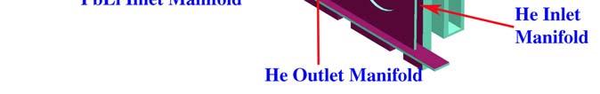
20 Mechanical Attachment of the Modular Blanket There are one helium access tube and one Pb-17Li access tube per blanket module to connect to the manifold behind shield. Each module needs two manifolds to provide the helium and Pb-17Li flows, the manifold with dimension of 35 x 25 cm, and inside manifold with a 23 cm O.D. tube. 20


21 Blanket Module Replacement Is Based on Cutting/Rewelding of the Outer Tube of the Concentric Pipes from the Outside after Removing the Neighboring Blanket Module or the Divertor 21


22 Steps to Cut the Coolant Connections from the outside through the Open Window Back View (From the Shield) 1.Remove the bottom piece in the radial direction. 22


23 Steps to Cut the Coolant Connections from the outside through the Open Window (cont.) 2.Lower the middle piece down vertically, then remove it in the radial direction. 23
 3.")

24 Steps to Cut the Coolant Connections from the outside through the Open Window(cont.) 3.Turn the top piece 90 degree, and lower it down to position of the bottom piece, 24 then remove it in the radial direction.


25 Steps to Cut the Coolant Connections from the outside through the Open Window(cont.) 4. Repeat the same procedures to remove the three pieces of shield around Pb- 17Li connection tube, then use tools to cut the both helium and Pb-17Li 25 connection tubes.

26 Alternative Way to Cut the Coolant Connection from the Open Window Alternative way(two cuts required for each tube) 26
27 Defining the Coolant Manifolds for the Modular Approach Maximum neutron wall load 4.5MW/m 2 Peak /Average ratio 1.62 Average neutron wall loading 2.78 Blanket energy multiply factor 1.10 Volumetric heating 2.52x10 3 MW Surface heat flux 0.5 MW/m 2 Total thermal power 2.93x10 3 Number of supply and return pipes per field-period(2 for LM, 2 for He) 4 Number of penetration through VV per field-period 4 Number of access tubes per module 2 Total number of access tube 502 Toroidal Pb-17Li supply/return pipe Thickness of the inner wall 0.5 cm I.D of the inner tube 48 cm Thickness of the outer tube 1.0 cm O.D. of the outer tube 72 cm Velocity 2.0 m/s Toroidal Helium supply/return pipe Thickness of the inner wall 0.5 cm I.D. of the inner tube 46 cm Thickness of the outer wall 1.5 cm O.D. of the outer tube 68 cm Velocity 100 m/s


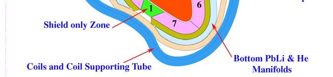
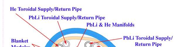
28 Layout of the Coolant Manifold and Supply/Return Pipes(Cross Section at 0 o ) There are 10 blanket modules. Supply/return pipes are placed inside of VV to reduce the penetrations of coolant access tubes through the VV. The Top PbLi & He Manifolds provide PbLi flow and He flow to blanket module #1 to module #5. Radial thickness of the manifold is assumed to be 45 cm. The Bottom PbLi & He Manifolds provide PbLi and He flows to blanket module # 6 to module #10. The Radial thickness of the manifolds are the same as the top manifolds. Cross-section at 0 o 28
 The Top PbLi & He")


29 Layout of the Coolant Manifolds and Supply/Return Pipes(Cross Section at 10 o ) The Top PbLi & He Manifolds supply PbLi flow and He flow to blanket module #1 to module #. Radial thickness of the manifold is assumed to be 35 cm. The Bottom PbLi & He Manifolds supply PbLi and He flows to blanket module # 5 to module #8. The Radial thickness of the manifolds are the same as the top manifolds. 29


30 Layout of the Coolant Manifolds and Supply/Return Pipes(Cross Sections at 20 o and 30 o ) 20 o 30 o 30


31 Layout of the Coolant Manifolds and Supply/Return Pipes(Cross Section at 40 o, 50 o and 60 o ) 40 o 50 o 60 o 31
32 Summary Dual-cooled blanket module design for the modular maintenance schemes is proposed. For an example max. Γ of 4.7 MW/m 2 and a limit of interface FS/LiPb temperature of 500 o C: η~40.7%, T max,fs <<554 o C, P pump /P thermal << 0.05 Blanket module replacement is based on cutting/re-welding of the outer tube of the concentric pipes from the outside after removing the neighboring blanket module or the divertor. Both helium and lead-lithium supply/return pipes are arranged inside of VV in order to reduce numbers of penetration through the VV. 32
PRELIMINARY ACT-2 POWER CORE DESIGN DEFINITION
 PRELIMINARY ACT-2 POWER CORE DESIGN DEFINITION X.R. Wang, C. Koehly, M. S. Tillack, S. Malang and F. Najmabadi ARIES-Pathways Project Meeting Germantown, DC May 21-22, 2013 OVERALL LAYOUT OF THE ACT-2
INTEGRATION OF THE MODULAR DUAL COOLANT PB-17LI BLANKET CONCEPT IN THE ARIES-CS POWER PLANT
 INTEGRATION OF THE MODULAR DUAL COOLANT PB-17LI BLANKET CONCEPT IN THE ARIES-CS POWER PLANT X.R. Wang 1, S. Malang 2, L.A. El-Guebaly 3, A. R. Raffray 1 and the ARIES Team 1 University of California, San
CONFIGURATION DESIGN AND MAINTENANCE APPROACH FOR THE ARIES-CS STELLARATOR POWER PLANT
 CONFIGURATION DESIGN AND MAINTENANCE APPROACH FOR THE ARIES-CS STELLARATOR POWER PLANT X.R. Wang 1, S. Malang 2, A. R. Raffray 1 and The ARIES Team 1 University of California, San Diego, CA, 9500 Gilman
Preliminary ARIES-RS-DCLL Radial Build for ASC
 Preliminary ARIES-RS-DCLL Radial Build for ASC L. El-Guebaly Fusion Technology Institute University of Wisconsin - Madison http://fti.neep.wisc.edu/uwneutronicscenterofexcellence Contributors: C. Kessel
UPDATES ON ARIES-ACT1 POWER CORE CONFIGURATION
 UPDATES ON ARIES-ACT1 POWER CORE CONFIGURATION AND SYSTEM INTEGRATION X.R. Wang, M. S. Tillack, S. Malang, C. Koehly, F. Najmabadi and the ARIES Team ARIES-Pathways Project Meeting UC San Diego January
DEMO FUSION CORE ENGINEERING: Blanket Integration and Maintenance
 DEMO FUSION CORE ENGINEERING: Blanket Integration and Maintenance 1.) Overview on European Blanket Concepts and Integration principles 2.) Large Module Integration 3.) Multi Module Segment (MMS) Integration
Approaches to Maintenance. S. Malang
 Approaches to Maintenance S. Malang FNST Meeting, UCLA, August 12-14, 2008 Areas involved in the selection of methods for blanket maintenance: (Emphasis may be different for FNF and DEMO) - Segmentation
Impact of Medium-Temperature Magnet and 2-FP Configuration on Radial Build
 Impact of Medium-Temperature Magnet and 2-FP Configuration on Radial Build Laila El-Guebaly Fusion Technology Institute University of Wisconsin - Madison With input from: L. Bromberg (MIT), J. Lyon (ORNL),
Alternative Design Options for a Dual-Cooled Liquid Metal Blanket for ARIES-ACT2
 University of California, San Diego UCSD-CER-13-02 Alternative Design Options for a Dual-Cooled Liquid Metal Blanket for ARIES-ACT2 C. Koehly, X. R. Wang, M. S. Tillack and F. Najmabadi August 2013 Center
Neutronic Performance Issues of the Breeding Blanket Options for the European DEMO Fusion Power Plant
 Neutronic Performance Issues of the Breeding Blanket Options for the European DEMO Fusion Power Plant U. Fischer, KIT Contributors C. Bachmann EUROfusion/PMU, Garching, Germany J. C. Jaboulay CEA Saclay,
Preliminary Neutronics Assessment of Molten Salt Blanket Concepts
 Preliminary Neutronics Assessment of Molten Salt Blanket Concepts Mohamed Sawan Fusion Technology Institute University of Wisconsin, Madison, WI ITER TBM Meeting UCLA Feb. 23-25, 2004 1 Preliminary Neutronics
State-of-the-Art 3-D Assessment of Elements Degrading TBR of ARIES-ACT SiC/LiPb Blanket
 State-of-the-Art 3-D Assessment of Elements Degrading TBR of ARIES-ACT SiC/LiPb Blanket L. El-Guebaly, A. Jaber, L. Mynsberge and the ARIES-ACT Team Fusion Technology Institute University of Wisconsin-Madison
Costing of Test Articles Ancillary Equipment and Costing Methodology
 Costing of Test Articles Ancillary Equipment and Costing Methodology 0.504 m x 1.71 m x 0.413 m C. Wong, S. Malang, M. Youssef, N. Morley, M. Ulrickson and the TBM design team US ITER-TBM Meeting August
ITER Shield Blanket Design Activities At SWIP
 1 ITER Shield Blanket Design Activities At SWIP F. Zhang 1), W. S. Kang 1), J. H. Wu 1), Y. K. Fu 1), J. M. Chen 1) F. Elio 2) 1) Southwestern Institute of Physics, P. O. Box 432 Chengdu, 610041, China
A Helium Cooled Particle Fuelled Reactor for Fuel Sustainability. T D Newton, P J Smith, Y Askan. Serco Assurance. Work Sponsored by BNFL
 Serco Assurance A Helium Cooled Particle Fuelled Reactor for Fuel Sustainability T D Newton, P J Smith, Y Askan Work Sponsored by BNFL Background New generation of reactor designs to meet the needs of
High Availability Remote Maintenance Approach for the European DEMO Breeder Blanket options
 1 High Availability Remote Maintenance Approach for the European DEMO Breeder Blanket options T. Ihli 1, D. Nagy 2, C. Koehly 1, J. Rey 1 1 Forschungszentrum Karlsruhe, Postfach 36 40, 76021 Karlsruhe,
Heat Exchangers (Chapter 5)
") Heat Exchangers (Chapter 5) 2 Learning Outcomes (Chapter 5) Classification of heat exchangers Heat Exchanger Design Methods Overall heat transfer coefficient LMTD method ε-ntu method Heat Exchangers Pressure
Heat Exchangers (Chapter 5) 2 Learning Outcomes (Chapter 5) Classification of heat exchangers Heat Exchanger Design Methods Overall heat transfer coefficient LMTD method ε-ntu method Heat Exchangers Pressure
IMPROVED BWR CORE DESIGN USING HYDRIDE FUEL
 Joint Reactor Seminar University of Tokyo (GoNERI) and UC Berkeley March 5, 2009 IMPROVED BWR CORE DESIGN USING HYDRIDE FUEL Massimiliano Fratoni, Alessandro Piazza, Ehud Greenspan University of California,
Re evaluation of Maximum Fuel Temperature
 IAEA Technical Meeting on on Re evaluation of Maximum Operating Temperatures and Accident Conditions for High Temperature Reactor Fuel and Structural Materials, 10 12 July 2012, Vienna, Austria Re evaluation
EU Procurement of In Vessel Components for ITER
 EU Procurement of In Vessel Components for ITER State of progress and next steps Patrick Lorenzetto ITER Business Forum 2013, Toulon, 21 22 March 2013 1 Content Blanket First Wall Procurement Package Blanket
PF Coil 2-6 Supply. Main technical aspects. P. Valente
 PF Coil 2-6 Supply Main technical aspects P. Valente PF Coils EI Information Meeting Cadarache, 19 February 2013 This presentation is intended for reference purposes only and is not a legally binding document
Single-phase Coolant Flow and Heat Transfer
 22.06 ENGINEERING OF NUCLEAR SYSTEMS - Fall 2010 Problem Set 5 Single-phase Coolant Flow and Heat Transfer 1) Hydraulic Analysis of the Emergency Core Spray System in a BWR The emergency spray system of
Key Stellarator Engineering Issues and Constraints
 Key Stellarator Engineering Issues and Constraints P. Heitzenroeder for the NCSX Engineering Team ARIES Meeting at PPPL - October, 2002 1 How The Engineering of a Compact Stellarator Differs from Most
CFD analysis of WCLL breeding blanket module design
 EUROFUSION WPBB-CP(16) 15521 A. Giovinazzi et al. CFD analysis of WCLL breeding blanket module design Preprint of Paper to be submitted for publication in Proceedings of 29th Symposium on Fusion Technology
1: CANDU Reactor. B. Rouben McMaster University Nuclear Reactor Physics EP 4D03/6D Sept-Dec September 1
 1: CANDU Reactor B. Rouben McMaster University Nuclear Reactor Physics EP 4D03/6D03 2015 Sept-Dec 2015 September 1 Outline A quick look at the design of CANDU Reactors: Reactor Assembly Pressure Tubes
Neutronics of Prismatic Fluoride Salt Cooled High Temperature Reactors
 Neutronics of Prismatic Fluoride Salt Cooled High Temperature Reactors Workshop on Advanced Reactors Concepts PHYSOR 2012 Knoxville, TN April 15, 2012 Dan Ilas IlasD@ornl.gov Main Neutronic Design Characteristics
Report No. IDO APPENDIX B ML-1 PLANT CHARACTERISTICS 1. GENERAL Mu to gas; 3.41 Mw total Cycle efficiency. Gross elect. wr. Net elect.
 ... Report No. IDO-28653 APPENDIX B ML-1 PLANT CHARACTERISTICS 0 Design performance at 100 F Gross electrical output Net electrical output 1. GENERAL Reactor thermal power 2.98 Mu to gas; 3.41 Mw total
ITER Vacuum Vessel Loads. Jake Blanchard October 2011
 ITER Vacuum Vessel Loads Jake Blanchard October 2011 Introduction As we consider alternative materials for our vacuum vessel, it is natural to compare to the ITER vessel To make appropriate use of their
GENERAL ATOMICS ITER CEnTRal SolEnoId ModulE FabRICaTIon September 2018
 GENERAL ATOMICS ITER Central Solenoid Module Fabrication September 2018 ITER Central Solenoid The heart of the international fusion energy device The Central Solenoid (CS) is the heart of ITER. The 5-story,
GENERAL ATOMICS ITER CENTRAL SOLENOID MODULE FABRICATION
 GENERAL ATOMICS ITER CENTRAL SOLENOID MODULE FABRICATION January 2018 ITER Central Solenoid The heart of the international fusion energy device The Central Solenoid (CS) is the heart of ITER. The 5-story,
CHAPTER 3 DESIGN OF THE LIMITED ANGLE BRUSHLESS TORQUE MOTOR
 33 CHAPTER 3 DESIGN OF THE LIMITED ANGLE BRUSHLESS TORQUE MOTOR 3.1 INTRODUCTION This chapter presents the design of frameless Limited Angle Brushless Torque motor. The armature is wound with toroidal
Supported by. NSTX Liquid Lithium Divertor Status, Plans, and Future Liquid Lithium R&D Needs
 NSTX Supported by NSTX Liquid Lithium Divertor Status, Plans, and Future Liquid Lithium R&D Needs College W&M Colorado Sch Mines Columbia U CompX General Atomics INEL Johns Hopkins U LANL LLNL Lodestar
Overview of the ITER In-Vessel coil (IVC)
") Overview of the ITER In-Vessel coil (IVC) 1. Purpose of the market survey With the present survey we would like to get from the Domestic Agencies a list of potential suppliers around the world for the
Overview of the ITER In-Vessel coil (IVC) 1. Purpose of the market survey With the present survey we would like to get from the Domestic Agencies a list of potential suppliers around the world for the
FUNDAMENTAL SAFETY OVERVIEW VOLUME 2: DESIGN AND SAFETY CHAPTER E: THE REACTOR COOLANT SYSTEM AND RELATED SYSTEMS
 PAGE : 1 / 13 4. PRESSURISER 4.1. DESCRIPTION The pressuriser (PZR) is a pressurised vessel forming part of the reactor coolant pressure boundary (CPP) [RCPB]. It comprises a vertical cylindrical shell,
Costing of Test Articles Ancillary Equipment and Costing Methodology
 Costing of Test Articles Ancillary Equipment and Costing Methodology 0.504 m x 1.71 m x 0.413 m C. Wong, S. Malang, M. Youssef, N. Morley, M. Ulrickson and the TBM design team US ITER-TBM Meeting August
Status of HPLWR Development
 Status of HPLWR Development Thomas Schulenberg SCWR System Steering Committee Karlsruhe Institute of Technology Germany What is a Supercritical Water Cooled Reactor? PH HP IP LP PH Produces superheated
Low Beta Cryomodule Development at Fermilab. Tom Nicol March 2, 2011
 Low Beta Cryomodule Development at Fermilab Tom Nicol March 2, 2011 Concepts of SC CW 3GeV, 1mA Linac H - gun RFQ MEBT SSR0 SSR1 SSR2 β=0.6 β=0.9 ILC RT (~15m) 325 MHz 2.5-160 MeV 650 MHz 0.16-2 GeV 1.3
Status of ITER at the Transition to Construction
 Status of ITER at the Transition to Construction Guenter Janeschitz Deputy Head of Central Integration Office ITER Organisation Page 1 Outline Fusion Basics and History of ITER (very brief): ITER and its
ANALYSIS OF BREST-OD-300 SAFETY DURING ANTICIPATED OPERATIONAL OCCURRENCES
 ANALYSIS OF BREST-OD-300 SAFETY DURING ANTICIPATED OPERATIONAL OCCURRENCES D.V. Didorin, V.A. Kogut, A.G. Muratov, V.V. Tyukov, A.V. Moiseev (NIKIET, Moscow, Russia) 1. Brief description of the aim and
GT-Suite Users Conference
 GT-Suite Users Conference Thomas Steidten VKA RWTH Aachen Dr. Philip Adomeit, Bernd Kircher, Stefan Wedowski FEV Motorentechnik GmbH Frankfurt a. M., October 2005 1 Content 2 Introduction Criterion for
Progress of the JT-60SA Project
 Progress of the JT-60SA Project P. Barabaschi, Y. Kamada, H. Shirai For the JT-60SA Integrated Project Team EU: F4E-CEA-ENEA-CNR/RFX-KIT-CIEMAT-SCKCEN JA: QST C.R.FRASCATI- ITALY 1 JT-60SA Project Agreement
NATIONAL NUCLEAR SECURITY ADMINISTRATION GLOBAL THREAT REDUCTION INITIATIVE Core Modifications to address technical challenges of conversion
 NATIONAL NUCLEAR SECURITY ADMINISTRATION GLOBAL THREAT REDUCTION INITIATIVE Core Modifications to address technical challenges of conversion G17 G18 G19 G20 G21 G16 F15 F16 G22 F17 F14 9.76 9.85 9.91 F18
KSTAR Assembly. National Fusion Research Center, Daejeon, Korea
 1 FT/2-2 KSTAR Assembly H. L. Yang, H. K. Kim, K. M. Kim, J. W. Sa, S. T. Kim, H. T. Kim, K. H. Hong, W. C. Kim, K. H. Kim, Y. S. Kim, J. Y. Kim, C. H. Choi, Y. K. Oh, Y. M. Park, M. Kwon, J. S. Bak, G.
Section 10 Chapter 20
 Section 10 Chapter 20 24 Valve, 8.3 Liter Engine Specifications Note: All coding used in the 8.3 Liter and 9 Liter engine manuals are Cuins engine codes. These engine codes have no meaning to New Holland
Design Study for Passive Shutdown System of the PGSFR
 Design Study for Passive Shutdown System of the PGSFR 2015. 10. 20 Lee, Jae-Han Koo, Gyeong-Hoi 20151021 IAEA TM on passive shutdown system 1 1. Reactor Control and Shutdown Concepts of PGSFR 6 Primary
THE Gersh Budker Prize PRIZE FOR.THE SUCCESSFUL CONSTRUCTION AND COMMISSIONING OF THE SPALLATION NEUTRON SOURCE
 THE Gersh Budker Prize PRIZE FOR.THE SUCCESSFUL CONSTRUCTION AND COMMISSIONING OF THE SPALLATION NEUTRON SOURCE EPAC08, Genoa (Italy) 26 June 2008 1451 1506 1918 1977 Norbert Holtkamp Principal Deputy
Advanced Cooling Technologies, Inc. Low-Cost Radiator for Fission Power Thermal Control NETS Conference
 Advanced Cooling Technologies, Inc. Low-Cost Radiator for Fission Power Thermal Control 2015 NETS Conference Advanced Cooling Technologies, Inc. Taylor Maxwell Calin Tarau Bill Anderson Vanguard Space
Heat Transfer Modeling using ANSYS FLUENT
 Lecture 7 Heat Exchangers 14.5 Release Heat Transfer Modeling using ANSYS FLUENT 2013 ANSYS, Inc. March 28, 2013 1 Release 14.5 Outline Introduction Simulation of Heat Exchangers Heat Exchanger Models
Rocketdyne Development of the Supercritical CO 2 Power Conversion System
 Rocketdyne Development of the Supercritical CO 2 Power Conversion System Michael McDowell Program Manager Reactor & Liquid Metal Systems Hamilton Sundstrand, Space Land & Sea-Rocketdyne Page 1 Rocketdyne
ABB POWER SYSTEMS CONSULTING
 ABB POWER SYSTEMS CONSULTING DOMINION VIRGINIA POWER Offshore Wind Interconnection Study 2011-E7406-1 R1 Summary Report Prepared for: DOMINION VIRGINIA POWER Report No.: 2011-E7406-1 R1 Date: 29 February
Pumping Systems for ITER, FIRE and ARIES
 Pumping Systems for ITER, FIRE and ARIES P. W. Fisher Oak Ridge National Laboratory C. A. Foster Cryogenic Applications F, Inc. March 6, 2001 1 ITER Vacuum System Tritium compatible batch regenerating
Power and Particle Control in JT-60SA to Support and Supplement ITER and DEMO
 Power and Particle Control in JT-60SA to Support and Supplement ITER and DEMO Shinji Sakurai and JT-60SA design team Division of Advanced Plasma Research, Japan Atomic Energy Agency, Naka, Japan Abstract:
Recent Predictions on NPR Capsules by Integrated Fuel Performance Model
 Massachusetts Institute of Technology Department of Nuclear Engineering Advanced Reactor Technology Pebble Bed Project Recent Predictions on NPR Capsules by Integrated Fuel Performance Model Jing Wang
Evaluation of sealing performance of metal. CRIEPI (Central Research Institute of Electric Power Industry)
") 0 Evaluation of sealing performance of metal gasket used in dual purpose metal cask subjected to an aircraft engine missile CRIEPI (Central Research Institute of Electric Power Industry) K. SHIRAI These
0 Evaluation of sealing performance of metal gasket used in dual purpose metal cask subjected to an aircraft engine missile CRIEPI (Central Research Institute of Electric Power Industry) K. SHIRAI These
Pressurized Air Cooled Generators
 PGI Orlando Dec. 13, 2016 Pressurized Air Cooled Generators Mike Zborovsky New App Generator Portfolio Owner siemens.com Pressurized Air-Cooled Generator (SGenX-2000P) Table of content Introduction 3 Portfolio
Thermal analysis of IRT-T reactor fuel elements
 Thermal analysis of IRT-T reactor fuel elements A Naymushin, Yu Chertkov, I Lebedev and M Anikin National Research Tomsk Polytechnic University, TPU, Tomsk, Russia E-mail: agn@tpu.ru Abstract. The article
Installation Instructions
 2011-2013 LML DURAMAX COMPOUND-ADD 2011-2015 LML A Duramax TURBO KIT Add INSTALL A Turbo INSTRUCTIONS Compound Kit Installation Instructions 1-800-955-0476 - www.industrialinjection.com - info@industrialinjection.com
The Establishment and Application of TRACE/FRAPTRAN Model for Kuosheng Nuclear Power Plant
 The Establishment and Application of /FRAPTRAN Model for Kuosheng Nuclear Power Plant S. W. Chen, W. K. Lin, J. R. Wang, C. Shih, H. T. Lin, H. C. Chang, W. Y. Li Abstract Kuosheng nuclear power plant
Sustainable Energy Mod.1: Fuel Cells & Distributed Generation Systems
 Sustainable Energy Mod.1: Fuel Cells & Distributed Generation Systems Dr. Ing. Mario L. Ferrari Thermochemical Power Group (TPG) - DiMSET University of Genoa, Italy : fuel cell systems (hybrid systems)
Includes: 1. Upgraded Tube Type EGR Cooler 2. Silicone Hoses
 Includes: 1. Upgraded Tube Type EGR Cooler 2. Silicone Hoses CAUTION: Never work on a hot vehicle. The hot exhaust system or hot engine can cause serious injury in the form of burns. If the vehicle has
ITER G A0 FDR R1.0
 2.1 Magnets 2.1.1 Magnet System General Description 1 2.1.1.1 System Description and Main Parameters 1 2.1.1.2 Physical and Functional Interfaces 4 2.1.1.3 Heat Loads 6 2.1.2 Magnet Structures 7 2.1.2.1
SUPERCHARGER AND TURBOCHARGER
 SUPERCHARGER AND TURBOCHARGER 1 Turbocharger and supercharger 2 To increase the output of any engine more fuel can be burned and make bigger explosion in every cycle. i. One way to add power is to build
The further development of WWER-440 fuel design performance. Authors: V.B.Lushin, I.N.Vasilchenko, J.A.Ananjev, G.V.Abashina OKB "GIDROPRESS".
 The further development of WWER-440 fuel design performance Authors: V.B.Lushin, I.N.Vasilchenko, J.A.Ananjev, G.V.Abashina OKB "GIDROPRESS". 1 Introduction VVER fuel development is determined by two main
Gas Power System. By Ertanto Vetra
 Gas Power System 1 By Ertanto Vetra Outlines Introduction Internal Combustion Engines Otto Cycles Diesel Cycles Gas Turbine Cycles Gas Turbine Based Combined Cycles Gas Turbines for Aircrafts Turbojets
NEW TECHNOLOGIES IN COLD CHAMBER DIE CASTING PROCESS ACCORDING TO INDUSTRY 4.0
 NEW TECHNOLOGIES IN COLD CHAMBER DIE CASTING PROCESS ACCORDING TO INDUSTRY 4.0 Jürgen Lamparter Director Sales Cold Chamber Die Casting Machines Oskar Frech GmbH + Co. KG, 73614 Schorndorf, Germany AGENDA
Fueling System Proposal for KSTAR
 Fueling System Proposal for KSTAR D.A. Rasmussen, L.R. Baylor, S. K. Combs, M.J. Cole, P.B. Parks* Oak Ridge National Laboratory KSTAR fueling system parameters Parameter Gas Fueling System Pellet Fueling
Evaluation of the Adequacy of Lithium Resources for Fusion Reactor with the Aspect of Li-ion Battery-Driven Vehicles
 Evaluation of the Adequacy of Lithium Resources for Fusion Reactor with the Aspect of Li-ion Battery-Driven Vehicles Chao Wang Contributed by FDS Team Key Laboratory of Neutronics and Radiation Safety
M. A. Green, and S. Yu Lawrence Berkeley National Laboratory, Berkeley CA 94720, USA
 LBNL-48445 SCMAG-749 SUPERCONDUCTING MAGNETS FOR INDUCTION LINAC PHASE-ROTATION IN A NEUTRINO FACTORY M. A. Green, and S. Yu Lawrence Berkeley National Laboratory, Berkeley CA 94720, USA ABSTRACT The neutrino
GENERAL ATOMICS ITER CEnTRal SolEnoId ModulE FabRICaTIon August 2016
 GENERAL ATOMICS ITER Central Solenoid Module Fabrication August 2016 ITER Central Solenoid The heart of the international fusion energy program The Central Solenoid (CS) is the heart of ITER. The 5-story,
Sensitivity of an Operating Supercritical Carbon Dioxide Brayton Cycle to Compressor and Turbine Inlet Temperature
 Bechtel Marine Propulsion Corporation Bettis Atomic Power Laboratory West Mifflin, PA Sensitivity of an Operating Supercritical Carbon Dioxide Brayton Cycle to Compressor and Turbine Inlet Temperature
Revision 9 January 9, 2019
 Kalsi Seals Handbook Chapter C5 Enhanced Lubrication Kalsi Seals Revision 9 January 9, 2019 Individual chapters of the Kalsi Seals Handbook are periodically updated. To determine if a newer revision of
Advantages of a Magnetically Driven Gear Pump By Steven E. Owen, P.E.
 Advantages of a Magnetically Driven Gear Pump By Steven E. Owen, P.E. Introduction Before considering a magnetically driven pump for use in a fluid system, it is best to know something about the technology
Paper No: 05-IAGT-1.1 INDUSTRIAL APPLICATION OF GAS TURBINES COMMITTEE
 Paper No: 05-IAGT-1.1 INDUSTRIAL APPLICATION OF GAS TURBINES COMMITTEE Mercury 50 Field Evaluation and Product Introduction by David Teraji of Solar Turbines Incorporated San Diego, California, USA 1 AUTHORS
A Linear Magnetic-geared Free-piston Generator for Range-extended Electric Vehicles
 A Linear Magnetic-geared Free-piston Generator for Range-extended Electric Vehicles Wenlong Li 1 and K. T. Chau 2 1 Department of Electrical and Electronic Engineering, The University of Hong Kong, wlli@eee.hku.hk
MODULAR WATER CHARGE AIR COOLING FOR COMBUSTION ENGINES
 DEVELOPMENT Thermal management MODULAR WATER CHARGE AIR COOLING FOR COMBUSTION ENGINES Valeo shows which considerations were taken into account with the development of a modular water charge air cooling
Application of Serpent in EU FP7 project FREYA: Fast Reactor Experiments for hybrid Applications
 Application of Serpent in EU FP7 project FREYA: Fast Reactor Experiments for hybrid Applications E. Fridman Text optional: Institutsname Prof. Dr. Hans Mustermann www.fzd.de Mitglied der Leibniz-Gemeinschaft
Interconnected Power Systems with Superconducting Magnetic Energy Storage
 Extended Summary pp.251 256 Interconnected Power Systems with Superconducting Magnetic Energy Storage Shinichi Nomura Member (Tokyo Institute of Technology, shin@nr.titech.ac.jp) Takushi Hagita Non-member
Installation Instructions
 BD DODGE CUMMINS PERFORMANCE E X H A U S T M A N I F O L D Installation Instructions Application List 2007-2015 6.7L / HE351 OE Turbo 1045965 2007-2015 6.7L / T4 S400 Turbo s 1045965-T4 PLEASE READ ALL
GENERAL The Honeywell model TFE731-40AR turbofan engine is a lightweight, two-spool, geared-stage, front-fan, jet engine.
 ENGINE GENERAL The Honeywell model TFE731-40AR turbofan engine is a lightweight, two-spool, geared-stage, front-fan, jet engine. The cross section of the engine is shown in Figure 7-71-1, page VII-71-3.
Experimental study of DHC. cladding and implications. dry storage conditions
 17th ASTM International Symposium Zirconium in the Nuclear Industry 03-07 February, 2013, Hyderabad, India Experimental study of DHC of unirradiated d and irradiated d fuel cladding and implications to
STUDY ON COMPACT HEAT EXCHANGER FOR VEHICULAR GAS TURBINE ENGINE
 Proceedings of Fifth International Conference on Enhanced, Compact and Ultra-Compact Heat Exchangers: Science, Engineering and Technology, Eds. R.K. Shah, M. Ishizuka, T.M. Rudy, and V.V. Wadekar, Engineering
Modeling of Underfloor Air Distribution (UFAD) Systems
 Systems") Modeling of Underfloor Air Distribution (UFAD) Systems Tom Webster, Fred Bauman, Center for the Built Environment (CBE) Fred Buhl, Lawrence Berkeley National Laboratory (LBNL) Allan Daly, Taylor Engineering
Modeling of Underfloor Air Distribution (UFAD) Systems Tom Webster, Fred Bauman, Center for the Built Environment (CBE) Fred Buhl, Lawrence Berkeley National Laboratory (LBNL) Allan Daly, Taylor Engineering
The Heating Mode Of Cable Transformer With Cooling System
 The Heating Mode Of Cable Transformer With Cooling System Titkov, V.V., Tukeev P.D. Department of High Voltage Engineering, Electrical Insulation and Cable Technology, Institute of Power Engineering and
STEAM TURBINE CALCULATION SHEET Page : 1
 STEAM TURBINE CALCULATION SHEET Page : 1 STEAM CONSUMPTION 1 EXTRACTION TURBINE 2 Turbine type CURTIS+REACTION 3 Control stage : Curtis 4 CONDENSING TURBINE 5 REQUIRED CONDITION 6 Normal Rated 7 Steam
Numerical Simulation of the Thermoelectric Model on Vehicle Turbocharged Diesel Engine Intercooler
 Research Journal of Applied Sciences, Engineering and Technology 6(16): 3054-3059, 013 ISSN: 040-7459; e-issn: 040-7467 Maxwell Scientific Organization, 013 Submitted: January 1, 013 Accepted: January
M-8100EP. Installation Guide ENGINEERED PLASTIC MANIFOLD SERIES. Introduction. A. Assemble Manifold Components
 Introduction The Pro Manifolds with Integrated adaptor are designed for use in Hydronic radiant panel heating and cooling applications. They are available in various sizes, configurations, and options
A1-F402B-MMI February 2003 Page A
 1 February 2003 Page A NUMERICAL INDEX OF EFFECTIVE WORK PACKAGES/PAGES List of Current Changes Original...0...1 February 2003 (IRACs 4 thru 8 Inc.) Only those pages assigned to the manual are listed in
Operation Results of a Closed Supercritical CO2 Simple Brayton Cycle
 Operation Results of a Closed Supercritical CO2 Simple Brayton Cycle JaeEun Cha*, Seong Won Bae*, Jekyoung Lee**, Song Kuk Cho**, JeongIk Lee**, Joo Hyun Park*** * Korea Atomic Energy Research Institute
COMPRESSOR STATION OPERATIONS
 CONTENTS FIGURES AND TABLES... viii PREFACE... xi ACKNOWLEDGEMENTS... xiii CHAPTER 1. INTRODUCTION... 1 Scope and Outline... 1 Types of Stations... 2 Production Stations... 2 Storage Stations... 3 Transmission
Permanent Magnet Machines for Distributed Generation: A Review
 Permanent Magnet Machines for Distributed Generation: A Review Paper Number: 07GM0593 Authors: Tze-Fun Chan, EE Department, The Hong Kong Polytechnic University, Hong Kong, China Loi Lei Lai, School of
HERCULES-2 Project. Deliverable: D8.8
 HERCULES-2 Project Fuel Flexible, Near Zero Emissions, Adaptive Performance Marine Engine Deliverable: D8.8 Study an alternative urea decomposition and mixer / SCR configuration and / or study in extended
Improvement of Irradiation Capability in the Experimental Fast Reactor Joyo
 IAEA Technical Meeting November, 2008 Improvement of Irradiation Capability in the Experimental Fast Reactor Joyo Tomonori Soga Fast Reactor Technology Section Experimental Fast Reactor Department O-arai
Oil/Air Cooler Units. Mobile application and Hydraulic motor OK ELH Type. Test procedure certified following EN 1048
 MOBILE OIL / AIR COOLERS NEW COMPACT DESIGN WITH HYDRAULIC MOTOR AND HIGH COOLING PERFORMANCE Application These coolers are designed specifically for mobile hydraulic applications where high performance
Idealizations Help Manage Analysis of Complex Processes
 8 CHAPTER Gas Power Cycles 8-1 Idealizations Help Manage Analysis of Complex Processes The analysis of many complex processes can be reduced to a manageable level by utilizing some idealizations (fig.
The Performance Optimization of Rolling Piston Compressors Based on CFD Simulation
 Purdue University Purdue e-pubs International Compressor Engineering Conference School of Mechanical Engineering 2004 The Performance Optimization of Rolling Piston Compressors Based on CFD Simulation
IMP Klima. Swirl diffusers. Variable swirl diffusers
 Swirl diffusers Variable swirl diffusers OD-4 OD-11, OD-11V OD-17 OD-7 OD-9 OD-5 OD-14 KD-8 OD-8 OD- 180 242 263 2.7 276 342 368 342 4 4 442 442 560 560 460 460 295x295 295x295 0 395x395 395x395 0 495x495
We are IntechOpen, the first native scientific publisher of Open Access books. International authors and editors. Our authors are among the TOP 1%
 We are IntechOpen, the first native scientific publisher of Open Access books 3,350 108,000 1.7 M Open access books available International authors and editors Downloads Our authors are among the 151 Countries
CONTROL SYSTEM DESIGN FOR A SMALL PRESSURIZED WATER REACTOR
 CONTROL SYSTEM DESIGN FOR A SMALL PRESSURIZED WATER REACTOR Peiwei Sun and Jianmin Zhang Xi'an Jiaotong University No. 28 Xianing Road West, Xi'an, Shaanxi 710049, China sunpeiwei@mail.xjtu.edu.cn; zhangjm@mail.xjtu.edu.cn
A Homopolar Inductor Motor/Generator and Six-step Drive Flywheel Energy Storage System
 A Homopolar Inductor Motor/Generator and Six-step Drive Flywheel Energy Storage System Perry Tsao, Matt Senesky, Seth Sanders University of California, Berkeley Perry s thesis defense presented www-power.eecs.berkeley.edu
New propulsion systems for non-road applications and the impact on combustion engine operation
 Research & Technology, New Propulsion Systems (TR-S) New propulsion systems for non-road applications and the impact on combustion engine operation London, 14 th March 2014, Benjamin Oszfolk Content 1