Installation and Operations Manual
|
|
|
- Roxanne Newman
- 5 years ago
- Views:
Transcription


1 FoamLogix Models 3.3 / 5.0 / 6.5 Electronic Foam Proportioning System Installation and Operations Manual tm Hale Products Inc. A Unit of IDEX Corporation 700 Spring Mill Avenue Conshohocken, PA U.S.A. Telephone: FAX: Web: Manual
2 APPARATUS INFORMATION ENGINE TRANSMISSION MAXIMUM CAFS ENGINE RPM CAFS ENGINE SPEED RANGE NOTICE! Class1 cannot assume responsibility for product failure resulting from improper maintenance or operation. Class1 is responsible only to the limits stated in the product warranty. Product specifications contained in this manual are subject to change without notice. All Class1 products are quality components -- ruggedly designed, accurately machined, precision inspected, carefully assembled and thoroughly tested. In order to maintain the high quality of your unit, and to keep it in a ready condition, it is important to follow the instructions on care and operation. Proper use and good preventive maintenance will lengthen the life of your unit. ALWAYS INCLUDE THE UNIT SERIAL NUMBER IN YOUR CORRESPONDENCE. ECO NO REV CHANGE FROM BY DATE APVD A Initial Release, for Printing PRW 05/02/2003 MAL B Updated PRW 06/30/2003 MAL 0032 C Updated to Latest Mfg. Build LwH 04/20/2005 MAL D Revised Drawing Update LwH 06/14/2007 MAL HALE PRODUCTS, INC. A Unit of IDEX Corporation Conshohocken, PA USA DRAWN BY LwH ISSUE DATE COPYRIGHT CHECKED BY PRW 06/14/2007 NOT TO BE REPRODUCED OR USED TO MAKE OTHER DRAWINGS OR MACHINERY. Manual, Rev. -D Printed in U.S.A. Hale Products, Inc All Rights Reserved
3 Table of Contents Contents Page FoamLogix 3.3 / 5.0 / 6.5 Installation and Operations How to use this manual Safety Precautions Guidelines System Overview Rotary Gear Pump Control Unit Water FLow Sensor Feed Back Sensor Table 2-1: Maximum Foam Solution Flows Tank Selector Valves Air Dual Tank Selector (ADT)...19 Manual Dual Tank Selector (MDT II)...19 Manual Single Tank (MST) Low Pressure Strainer Hale FS Series Strainers Ordering Information Hale Foam System Specifications Figure 2-2: Foam Pump Installation Envelope Dimensions...23 Figure 2-3: Foam Pump Installation Envelope Dimensions, ADT Option Only System Configuration Hale Foam Proportioner System, Models 3.3 or Figure 2-4: FoamLogix Available Models...25 Figure 2-5: Hale Foam Proportioner Systems, Models 3.3 and Cable Harness Main Cable Harness, Single Tank...26 Figure 2-6: Single Tank Cable Harness...26 Main Cable Harness, Dual Tank...27 Figure 2-7: Dual Tank Cable Harness...27 Figure 2-8: Power Connection Wire Harness
4 Table of Contents Contents - continued Page 2.11 Dual Foam Concentrate Tank System Options Figure 2-9: Dual Tank Foam Concentrate Tank System Options Dual Foam Concentrate Tank Options Single Foam Concentrate Tank Options Strainer Options Low Tank Level Sensor Options Flow Sensors Check Valve Manifolds Remote Activation Switch Option Check Valves, Flanges, Gaskets Elbows and Mini Manifolds Hale Foam System Layout Drawings Figure 2-10: Typical Single Foam Concentrate Tank Figure 2-11: Single Foam Tank with MST and In-Line Strainer/Valve Assembly Figure 2-12: Single Foam Tank with MST and FS Series Strainers Figure 2-13: Dual Foam Concentrate Tanks, with MDT II and In-Line Strainer/Valve Assembly...42 Figure 2-14: Dual Foam Concentrate with MDT II and FS Series Strainer Assembly Figure 2-15: Dual Foam Concentrate Tanks, with ADT and In-Line Strainer/Valve Assemblies Figure 2-16: Dual Foam Concentrate Tanks with ADT and FS Series Strainer Assemblies Installation Foam Pump and Motor Assembly Foam Concentrate Strainer Control Unit / Instruction Placard Installer Supplied Components Foam Concentrate Suction Hose Recommended Components Recommended Components Foam Concentrate Discharge Hose...51 Recommended Components
5 Table of Contents Contents - continued Page 3.4 Installer Supplied Components - continued Foam Concentrate Bypass Hose...52 Recommended Components...52 Check Valves...52 Flushing Water Hose...53 Foam Discharge Drains...54 Electrical Requirements...54 Figure 3-1: Recommended Relay Wiring Schematic...55 Table 3-2: Primary Power Cable Sizes...55 FoamLogix Display...56 Foam Concentrate Tanks(s)...56 Table 3-3: Recommended Foam Tank Capacity...57 Foam Pump Mounting...57 Figure 3-4: FoamLogix Pump Installation...57 Figure 3-5: Base Plate Mounting Hole Locations...58 Plumbing Installation...59 Water and Foam Solution Plumbing...59 Figure 3-6: Typical Check Valve Manifold Installation...59 Optional Hale Piping Components...60 Figure 3-7: Typical Midship Pump Installation...61 Figure 3-8: 4 (102mm) Check Valve Installation...61 Waterway Check Valves...62 Flow Sensor...62 Figure 3-9: Flow Sensor Tee Position Range...62 Table 3-10: Pipe Size vs. Minimum Straight Run...63 Figure 3-11: Typical Reduced Size Sensor Piping Arrangement...63 Figure 3-12: Flow Sensor Placement...64 Saddle Clamp Installation...64 Figure 3-13: Flow Sensor/Saddle Clamp Installation...65 Foam Pump Flush System...65 Dual Tank System...65 Single Tank System...65 No Tank Option...65 Foam Concentrate Plumbing...66 Foam Strainer Connection (In-Line Strainer/Valve)...66 Figure 3-14: In-Line Strainer/Valve Installation...67 To Install the In-Line Strainer/Valve Assembly...67 Figure 3-15: In-Line Strainer Mounting Bracket Layout
6 Table of Contents Contents - continued Page 3.4 Installer Supplied Components - continued FS Series Strainer To Install FS Series Strainers Figure 3-16: FS Strainer Orientation Figure 3-17: FS Strainer Mounting Dimensions Check Valve/Injector Fitting Figure 3-18: Check Valve/Injector Fitting Orientation Figure 3-19: Check Valve/Injector Fitting Installation Foam Concentrate Injection Hose Figure 3-20: Injection and Bypass Hose Connections Bypass Hose Connection Figure 3-21: Bypass Valve Assembly ADT Option Air Connections Figure 3-22: ADT Option Panel Placard Layout Dimensions Figure 3-23: ADT Air Hose Connections, Part Figure 3-24: ADT Option Air Hose Connections, Part System Plumbing Diagrams Figure 3-25: Typical Single Foam Concentrate Tank Figure 3-26: Typical Single Foam Tank with MST and In-Line Strainer/Valve Assembly...79 Figure 3-27: Typical Single Foam Tank, with MST and FS Series Strainers Figure 3-28: Single Foam Tank with MST II and In-Line Strainer/Valve Assembly Figure 3-29: Typical Single Foam Tank with MST II and FS Series Strainers Figure 3-30: Typical Single Foam Tank with ADT and In-Line Strainer/Valve Assemblies Figure 3-31: Typical Dual Foam Tanks, with ADT and FS Series Strainer Assemblies Electrical Single and Dual Tank Electrical Harness Overview Figure 3-32: Single Tank Electrical Harness Overview Figure 3-33: Dual Tank Electrical Harness Overview Control / Display Unit Figure 3-34: Control/Display Unit Mounting Dimensions Figure 3-35: Control Cable Harness Connections, Single Tank Shown Figure 3-36: Distribution Box Connections Distribution Box Ground / Primary Power...91 RFI / EMI Figure 3-37: Extra Cable Storage
7 Table of Contents Contents - continued Page 3.6 Electrical - continued Flow Sensor Connections...93 Low Level Sensor Installation (Foam Tank)...93 Figure 3-38: Low Level Sensor Mounting Options...93 Figure 3-39: Side Mount Sensor Location Dimensions...94 Figure 3-40: Top Mount Sensor Dimensions...95 Figure 3-41: Top Mount Low Level Sensor Assembly...97 Low Level Sensor Wiring...98 Remote Activation Switch Option Figure 3-42: Remote Activation Switch Installation Dimensions Start Up Check List Electrical Liquid Foam Pump Optional ADT Installation and Delivery Check List System Installer Start-UP Initial System Power Check Figure 3-43: Initial Start-Up, System Ready Displays System Operation Check Figure 3-44: Simulated Flow Mode Display User Setup and Calibration Initial End User Setup Figure 4-1: Initial Start-Up, System Ready Displays System Power Check Priming the Foam Pump Figure 4-2: Simulated Flow Mode Display User Calibration Entering Passwords Figure 4-3: Password Sequence Restoring Factory Defaults Figure 4-4: Password and Calibration Modes - Display Calibration Flow Sensor Calibration Figure 4-5: Flow Sensor Calibration - Display
8 Table of Contents Contents - continued Page 4.2 User Calibration - continued Record Calibration Factors Figure 4-6: Flow Sensor Calibration Factor Simulated Flow Figure 4-7: Simulated Flow Calibration Foam Concentrate Injection Rate Figure 4-8: Foam Concentrate Injection Rate Default Value, Tank A Shown Foam Pump Feedback Calibration Figure 4-9: Foam Pump Feedback Calibration, Tank A Shown Figure 4-10: Foam Concentrate Collection Figure 4-11: Feedback Calibration Factor, Tank A Shown Exit and Save Calibration Figure 4-12: Exit and Save Calibration Relief Valve Figure 4-13: Relief Valve English to Metric Units Operation Description Figure 5-1: Control Unit Identification Control Display Unit Control Unit Functions Figure 5-2: Function Modes Reset Functions Foam Concentrate Injection Rate Flush Figure 5-3: Flush Warning Messages Low Foam Tank Level Message Figure 5-4: Low Foam Tank Message, Tank A Shown Priming Message High Ambient Temperature Message Figure 5-5: Priming, HIGH Temperature and LOW Battery Messages Priming the Foam Pump
9 Table of Contents Contents - continued Page 5.8 Normal Operation Summary Energize System Select Foam Tank Figure 5-6: Normal Operation Summary Chart Begin Foam Injection Change Injection Rate Read Injection Rate Read Total Water or Foam Solution Read Total Foam Concentrate Reset Totalized Values End Foam Injection Simulated Flow Mode Operation Simulated Flow Sequence Figure 5-7: Simulated Flow Display Sequence Dual Tank System Selection Figure 5-8: Dual Tank Selector Operating Positions Flushing Hale FoamLogix Figure 5-9: Hale MST Selector Operation Remote On/Off Switch Option To operate: Figure 5-10: Remote Activation Switch Maintenance Maintenance Procedures After each use Monthly Every Two (2) Months Annually Troubleshooting User Diagnostics Figure 7-1: Distribution Box Overview System Overview Figure 7-2: FoamLogix, Closed Loop Flow Diagram Distribution Box Pump / Motor Bar Graph Summary
10 Table of Contents Contents - continued Page 7.3 Problem Isolation Flow Charts Chart 7-3: Hale FoamLogix System Troubleshooting Flow Chart Chart 7-4: Power System Troubleshooting Appendix A: Foam Concentrate Compatibility Chart A-1: Hale Class A Foam Concentrate Compatibility Chart A-2: Hale Class B Foam Concentrate Compatibility Reference Express Warranty Hale Products, Inc Illustrated Parts Breakdown General Abbreviations Air Dual Tank Valve (ADT) Option Harness Components Dual Foam Concentrate Tank Options Single Foam Concentrate Tank Options Low Tank Level Sensor Options Flow Sensors Main Cable Harness, Single and Dual Tank Check Valve Manifolds Remote Activation Switch Option Check Valves, Flanges, Gaskets Elbows and Mini Manifolds Plate Drawings
11 How To Use This Manual How to use this manual This manual is divided into eight (8) sections for clarity and ease of use. Each of the following sections can be stand alone or used in conjunction with each other. 1 SAFETY This section must be carefully read, understood and adhered to strictly by all installer/builders, operators and service personnel using the Hale Foam- Logix, Models 3.3 and 5.0, Foam Proportioning System. Do not use or install the system until you have thoroughly read this section. Failure to comply could cause serious injury to yourself and others, or damage to the system. 2 INTRODUCTION System overview provides an introduction to the Hale FoamLogix Proportioning System along with guidelines for designing and ordering a complete system. 3 INSTALLATION This section offers installer/builder installation procedures, plumbing overview diagrams, electrical installation and startup and delivery check lists, to assist the OEM with installation and initial setup of Hale FoamLogix Proportioning System on an apparatus. 4 USER CALIBRATION User calibration is used by the installer and the end user for start-up and calibration of the Hale FoamLogix Proportioning System to produce the proper foam flow. 11
12 How To Use This Manual 5 OPERATION The Operation section primarily used by the apparatus user for proper operation and maintenance of the Hale FoamLogix Proportioning System. It is a guide to the operation of the system and includes operating procedures for the most commonly used options. 6 GENERAL MAINTENANCE This section describes the routine inspection and maintenance requirements for the Hale FoamLogix System. 7 TROUBLESHOOTING If a problem develops, see this section for troubleshooting procedures. 8 PARTS IDENTIFICATION Section 8 includes a parts breakdown of the most commonly used parts of the FoamLogix 3.3 and 5.0 Systems. Also see Plate Drawings for parts identification and system layout. 12
13 Safety Precautions 1 Safety Precautions IMPORTANT! THE HALE FOAMLOGIX MODELS 3.3 AND 5.0 ELECTRONIC FOAM PRO- PORTIONING SYSTEMS ARE DESIGNED FOR OPTIMUM SAFETY OF ITS OPERATORS AND TO PROVIDE RELIABLE AND SAFE FOAM CONCENTRATE INJECTION. FOR ADDED PROTECTION AND BEFORE ATTEMPTING INSTAL- LATION OR OPERATION PLEASE FOLLOW THE SAFETY GUIDELINES LISTED IN THIS SECTION. ADHERE TO ALL WARNING, DANGER, CAUTION AND IMPORTANT NOTES FOUND WITHIN THIS GUIDE. THIS SECTION ON SAFETY MUST BE CAREFULLY READ, UNDERSTOOD AND ADHERED TO STRICTLY BY ALL INSTALLERS AND SYSTEM OPERA- TORS BEFORE ATTEMPTING TO INSTALL OR OPERATE THE FOAMLOGIX FOAM PROPORTIONING SYSTEM. WHEN DEVELOPING DEPARTMENTAL APPARATUS OPERATING PROCE- DURES, INCORPORATE THE WARNINGS AND CAUTIONS AS WRITTEN. FoamLogix is a trademark of Hale Products, Incorporated. All other brand and product names are the trademarks of their respective holders. 1.1 GUIDELINES READ ALL INSTRUCTIONS THOROUGHLY BEFORE BEGINNING ANY INSTALLATION OR OPERATION PROCESS. Installation should be performed by a trained and qualified installer, or your authorized Hale Products Service Representative. Be sure the installer has sufficient knowledge, experience and the proper tools before attempting any installation. Make sure proper personal protective equipment is used when operating or servicing the apparatus. A foam tank low level sensor must be utilized to protect the Hale foam proportioner from dry running. Failure to use a low level sensor with the Hale Foam System voids warranty. DO NOT permanently remove or alter any guard or insulating devices, or attempt to operate the system when these guards are removed. Make sure all access/service panels and covers are installed, closed and latched tight, where applicable. 13
14 Safety Precautions DO NOT remove or alter any hydraulic or pneumatic connections, electrical devices, etc. DO NOT tamper with or disconnect safety features or modify protective guards (such as covers or doors). DO NOT add or remove structural parts. Doing so voids the warranty. Any of the above could affect system capacity and/or safe operation of the system and is a serious safety violation which could cause personal injury, could weaken the construction of the system or could affect safe operation of the FoamLogix Proportioning System. WARNING! NO MODIFICATIONS OR ADDITIONS MAY BE MADE TO THE FOAMLOGIX PROPORTIONING SYSTEM WITHOUT PRIOR WRITTEN PERMISSION FROM: Hale Products, Incorporated Fire Suppression Division 700 Spring Mill Avenue Conshohocken, PA Telephone: Fax: To prevent electrical shock always disconnect the primary power source before attempting to service any part of the Hale FoamLogix System. All electrical systems have the potential to cause sparks during service. Take care to eliminate explosive or hazardous environments during service and/or repair. To prevent system damage or electrical shock the main power supply wire is the last connection made to the Hale Foam Proportioner Distribution Box. Release all pressure then drain all concentrate and water from the system before servicing any of its component parts. Do not operate the system at pressures higher than the maximum rated pressure. Use only pipe, hose, and fittings from the foam pump outlet to the injector fitting, which are rated at or above the maximum pressure rating at which the water pump system operates. Hale Foam proportioning systems are designed for use on negative ground direct current electrical systems only. Do not mount radio transmitters or transmitter cables in direct or close contact with the FoamLogix Control Unit. 14
15 Safety Precautions Before connecting the cord sets and wiring harnesses, inspect the seal washer in the female connector. If the seal washer is missing or damaged, water can enter the connector causing corrosion. This could resulting in possible system failure. Always disconnect the power cable, ground straps, electrical wires and control cables from the control unit or other Hale Foam system equipment before electric arc welding at any point on the apparatus Failure to do so could result in a power surge through the unit that could cause irreparable damage. DO NOT connect the main power lead to small leads that are supplying some other device, such as a light bar or siren. The Hale FoamLogix, Models 3.3 and 5.0, require 60 AMP minimum current. When operating the Hale FoamLogix in Simulated Flow Mode, an outlet for the foam concentrate must be provided to prevent excessive pressure buildup in the discharge piping or hoses. Unless engaged in Class B foam operations, the air dual tank (ADT) toggle switch, or the manual dual tank (MDT) II selector handle must be in the TANK A or FLUSH position. If either is in the FLUSH position when the foam system is started, the foam pump runs for approximately twenty (20) seconds, then SHUTS DOWN. Make sure the foam tank and foam concentrate suction hoses are clean before making final connections to the foam pump. If necessary flush the tank and hoses prior to making connection. Check all hoses for weak or worn conditions after each use. Ensure that all connections and fittings are tight and secure. Ensure that the electrical source of power for the unit is a negative ( ) ground DC system, of correct input voltage, with a reserve minimum current available to drive the system. The in-line strainer/valve assembly is a low pressure device and CAN- NOT withstand flushing water pressure in excess of 45 PSI (3 BAR). When installing the in-line strainer in systems equipped with the Hale MDT II or MST, make sure the in-line strainer/valve assembly is installed on the inlet side of the valve. If the strainer is subjected to flushing water, install Hale FS Series strainers. When determining the location of the Hale FoamLogix System components keep in mind piping runs, cable routing and other interferences that could hinder or interfere with proper system performance. 15
16 Safety Precautions Always position the check valve/injector fitting at a horizontal or higher angle to allow water to drain away from the fitting. This avoids the possibility of sediment deposits or the formation of an ice plug. The cord sets provided with each Hale Foam system are 100% electrically shielded assemblies. NEVER attempt to shorten or lengthen the molded cables. If necessary, order longer or shorter cord sets to suit your application needs. Each cord sets provided is indexed to ensure correct receptacle installation (they insert one way only). When making cord set connections DO NOT force mismatched connections as damage can result in improper system operation. Make sure all connections are sound, and that each connection is correct. The cables shipped with each Hale Foam system are 100% tested at the factory with the unit. Improper handling and forcing connections can damage these cables which could result in other system damage. There are no user serviceable parts inside Hale Foam system electrical/ electronic components. Opening the distribution box, control unit, foam multiplexing display unit, etc., voids the warranty. Use mounting hardware that is compatible with all foam concentrates to be used in the system. Use washers, lock washers and cap screws made of brass or 300 series stainless steel. When making wire splice connections, make sure they are properly insulated and sealed using an adhesive filled heat shrink tubing. ALWAYS connect the primary positive power lead from the terminal block to the master switch terminal or the positive (+) battery terminal. Use a minimum 4 AWG type SGX (SAE J1127) chemical resistant battery cable and protect with wire loom. Prevent corrosion of power and ground connections by sealing these connections with the silicone sealant provided. Prevent possible short circuit by using the rubber boot provided to insulate the primary power connection at the Hale FoamLogix Distribution Box. 16
17 Introduction 2 System Overview The Hale FoamLogix Models 3.3 and 5.0 Foam Proportioning Systems are completely engineered, factory matched foam proportioning systems that provide reliable, consistent foam concentrate injection for Class A and Class B foam operations. Hale FoamLogix Foam Systems accurately deliver from 0.1% to 10.0% foam concentrate through a check valve/injector fitting, directly into the water discharge stream. It is then fed as foam solution into a standard fog nozzle, an air aspirated nozzle, or CAFS equipment, through the apparatus discharge piping. A properly configured and installed foam system with Hale recommended components virtually eliminates contamination of the booster tank, fire pump and relief valve with foam concentrate. 2.1 ROTARY GEAR PUMP The heart of the Hale FoamLogix 3.3 and 5.0 systems is an electric motor driven rotary gear pump. The pump is constructed of bronze and stainless steel and is compatible with almost all foam concentrates. The pump is close coupled to the electric motor thereby eliminating maintenance of an oil-filled gearbox. A relief valve mounted on the foam pump and constructed of stainless steel, protects the foam pump and foam concentrate discharge hoses from over pressurization and damage. 2.2 CONTROL UNIT The control unit, mounted on the operator panel, is the single control point for the FoamLogix system. Pressing the ON button starts foam concentrate injection. A super bright digital LED display shows the: Water flow rate Total water flow Foam concentrate injection percentage Total foam concentrate used, depending on the display mode selected A bar graph indicates the approximate system capacity being used. Adjustment of the foam concentrate injection rate is accomplished by pressing the appropriate button while the system is operating. 17
18 Introduction The control unit display also warns the operator if errors or abnormal operations occur in the system, such as low foam level. 2.3 WATER FLOW SENSOR The foam concentrate injection rate is controlled by a computer chip in the control unit for accurate, repeatable, reliable foam concentrate injection. A water flow sensor constantly monitors water flow through the discharge piping. The information from the flow sensor is provided to the control unit by a shielded cable. When the FoamLogix system is activated at the control unit a signal is sent through the control cable to the distribution box to begin foam concentrate injection. The distribution box then provides power to the electric motor. As the motor rotates the pump, foam concentrate flows through the foam pump discharge to the one piece check valve/injector fitting into the water discharge stream. Note: All Hale FoamLogix Foam systems require a flow sensor for operation. 2.4 FEED BACK SENSOR A feedback sensor in the foam pump discharge measures foam concentrate flow. The water flow rate and foam concentrate flow rate are constantly compared by the computer chip in the control unit. Injection Rate (Percent %) Maximum Foam Solution Flows Model 3.3 Model 5.0 GPM LPM GPM LPM 0.1 3,300 12,492 5,000 18, ,650 6,245 2,500 9, ,100 4,164 1,667 6,310 The motor speed is constantly ,498 1,000 3,785 adjusted to maintain the operator selected foam concentrate injection rate. Since the system is flow based, injection rate remains constant regardless , , of changes in system pressure or the number of discharges Table 2-1: Maximum Foam Solution Flows that are open (within the limits of the system). There are two models of Hale Foam systems covered by this manual. The Hale FoamLogix Model 3.3 (3.3GPM/12.5LPM) and Model 5.0 (5.0GPM/ 19LPM). The maximum rated foam concentrate flow in gallons per minute is denoted by the model number. Table 2-1: Maximum Foam Solution Flows shows system capacities at various foam concentrate injection rates for each Hale FoamLogix Model. 18
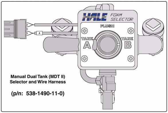
19 Introduction The maximum rated foam concentrate flow, in gallons per minute (and liters per minute), is denoted by the model number. Table 2-1: Maximum Foam Solution Flows on page 18 shows the system capacity at various foam concentrate injection rates for both models. The Hale FoamLogix 3.3 and 5.0 system configuration is shown in Figure 2-2: Foam Pump Installation Envelope Dimensions on page 23. Also see Figure 2-3: Foam Pump Installation Envelope Dimensions, ADT Option Only on page TANK SELECTOR VALVES Selection of the desired foam concentrate tank with the ADT panel mounted toggle switch or MDT II selector automatically changes the foam concentrate injection rate to the preset default rate for the selected foam tank. No further operator intervention is required. The ADT, MDT II and MST include the check valves and connection points to provide foam pump flushing capabilities. Air Dual Tank Selector (ADT) The Air Dual Tank (ADT) valve is an air operated foam tank selector valve that enables selection of foam concentrate dependent on fire ground operational demands. The ADT is an integral part of the foam pump and provides an electrical interlock for the low tank level sensors and concentrate injection rate. A panel mounted selector toggle switch with indicator lights controls foam concentrate tank selection and shows which foam concentrate tank is in use. Manual Dual Tank Selector (MDT II) The Manual Dual Tank (MDT II) selector valve is available for the Hale Foam systems with dual tanks. The MDT II is a panel mounted, manually operated selector that provides selection of foam concentrate dependent on fire ground operational demands. The MDT II also provides an electrical interlock for the low tank level sensors and concentrate injection rate. The MDT II is not suitable for top mount operator panel installations and some side operator panels due to gravity feed requirements of foam concentrate to the foam pump. 19
20 Introduction Manual Single Tank (MST) Single tank foam systems can be configured with a Manual Single Tank (MST) selector, which provides a flush function connection to the foam system electronic controls. 2.6 LOW PRESSURE STRAINER A low pressure foam concentrate strainer is mounted at the inlet of the foam pump. The strainer protects the pump from debris that might accumulate in the foam concentrate tank. The strainer and valve assembly has a composite nonmetallic housing with stainless steel mesh strainer element and includes a service shut-off valve and mounting bracket. The assembly uses a 1-1/4 (32mm) NPT thread and is supplied with fittings for connection of either 1-1/4 (32mm) ID, 1 (25mm) ID or 3/4 (19mm) ID foam concentrate suction hose. The in-line strainer and valve assembly is suitable for use with both Class A and Class B foam concentrates and is designed for installations where the strainer is mounted in the foam pump suction line. The strainer and valve are low pressure devices and are designed for installations where the strainer IS NOT subject to HIGH pressure flushing water. Hale FS Series Strainers Hale FS series strainers (FS15 and FS25) are panel mounted with a 500 PSIG (34 BAR) pressure rating, suitable for use where flushing water pressure must pass through the strainer. The FS15 strainer uses 3/4 (19mm) NPT connection ports and a 1-1/2 NST cap. It is suitable for use with Class A and low viscosity Class B foam concentrates. The FS25 strainer uses 1 (25mm) NPT connection ports and a 2-1/2 NST cap. It is suitable for use with both Class A and Class B foam concentrates. 2.7 ORDERING INFORMATION Use the current Hale FoamLogix Foam System Price List and Order Form to help ensure a complete matched system is provided to the end user. 20
21 Introduction Use the following procedure when ordering a Hale FoamLogix Foam System. Follow all steps to ensure that a complete system is ordered: 1. Check Hale Foam system product information update (Bulletin #961) for the latest information and advice for foam system selection. A copy of Bulletin #961 is located at the back of this manual. 2. Determine the type of foam concentrate being used in the system and ensure system compatibility by referring to the Hale Foam Concentrate Compatibility Chart. Also see Heading Appendix A: Foam Concentrate Compatibility on page Determine the Hale Foam system needed. Model 5.0 Model VDC 24 VDC motor 4. Determine tank selector needed based on the number of foam concentrate tanks installed. ADT... for dual tank systems MDT II... for dual tank systems MST... for single tank systems No Select.. for single tank systems - System installer/builder must provide flushing water connection to the foam pump. 5. Determine strainers needed. In-line Strainer and Valve Assembly FS 15 Strainer FS 25 Strainer 6. Determine the low tank level sensors needed. Side Mount Bottom Mount Top Mount Assembly 7. Select the flow sensor, then the mounting weld fitting or saddle clamp based on discharge pipe size. 21
22 Introduction 8. Select harness length. 10 feet flow sensor x 15 feet controller 15 feet flow sensor x 20 feet controller 9. Additional Hale components available to enhance system operation and ease installation include: Waterway Check Valves Manifolds Flanges Foam Tanks, etc. 10. Components shown in bold type represent the best value performance system. All components listed have been engineered and tested with Hale foam systems to provide optimum system performance. Using the information provided and the detailed ordering procedures on the option order form ensures a complete Hale foam system is ordered, thus eliminating delays caused by missing components. 11. System components are shown in the following heading Hale Foam System Specifications. 2.8 HALE FOAM SYSTEM SPECIFICATIONS (See Figure 2-2: Foam Pump Installation Envelope Dimensions, on page 23.) Also see Figure 2-3: Foam Pump Installation Envelope Dimensions, ADT Option Only on page 24. Foam Pump... Rotary Gear Positive Displacement Rated Foam Concentrate Output Model GPM (13 LPM) Model GPM (19 LPM) Maximum System Operating Pressure Model PSI (28 BAR) Model PSI (17 BAR) Maximum Operating Temperature F (71 C) Pump Motor Standard...3/4 HP (0.6 kw), 12 VDC Optional...3/4 HP (0.6 kw), 24 VDC 22
 Figure 2-2: Foam Pump Installation Envelope Dimensions (Configured for use with MDT II,")
23 Introduction Operating Ampere Draw AMPS at 12 VDC (15 AMPS at 24 VDC) Maximum Ampere Draw AMPS at 12 VDC (30 AMPS at 24 VDC) Figure 2-2: Foam Pump Installation Envelope Dimensions (Configured for use with MDT II, MST or No Tank Selection Options.) 23

24 Introduction Figure 2-3: Foam Pump Installation Envelope Dimensions, ADT Option Only 24
25 Introduction 2.9 SYSTEM CONFIGURATION Hale Foam Proportioner System, Models 3.3 or 5.0 All Hale Foam systems include a: Foam Pump/Motor Assembly, Control Unit, Main Harness and Check Valve/Injector Fitting. Also see Section 8 Illustrated Parts Breakdown on page 159. Control Unit p/n: Foam Pump/Motor Assembly (Shown with Bypass Valve when configured for MDT II, MST or No Tank Selector Option) FoamLogix Model Part Number Model 5.0, with 12VDC Motor Model 5.0 with 24VDC Motor Check Valve/Injector Fitting Model 3.3 with 12VDC Motor Model 3.3 with 24VDC Motor Figure 2-4: FoamLogix Available Models Figure 2-5: Hale Foam Proportioner Systems, Models 3.3 and
26 Introduction 2.10 CABLE HARNESS (See Figure 2-6: Single Tank Cable Harness. ) Also see Figure 2-7: Dual Tank Cable Harness on page Dual Tank Harness, 10 x 15 (3 x 4.6m) 10 - Flow Sensor x 15 - Controller Dual Tank Harness, 15 x 20 (3 x 6.1m) 15 - Flow Sensor x 20 - Controller Single Tank Harness, 10 x 15 (3 x 4.6m) 10 - Flow Sensor x 15 - Controller Single Tank Harness, 15 x 20 (3 x 6.1m) 15 - Flow Sensor x 20 - Controller Main Cable Harness, Single Tank Figure 2-6: Single Tank Cable Harness 26

27 Introduction Main Cable Harness, Dual Tank Figure 2-7: Dual Tank Cable Harness Figure 2-8: Power Connection Wire Harness 27

28 Introduction 2.11 DUAL FOAM CONCENTRATE TANK SYSTEM OPTIONS Figure 2-9: Dual Tank Foam Concentrate Tank System Options 28

29 Introduction 2.12 DUAL FOAM CONCENTRATE TANK OPTIONS 29

30 Introduction 2.13 SINGLE FOAM CONCENTRATE TANK OPTIONS 30

31 Introduction 2.14 STRAINER OPTIONS Note: For Hale FS Series Strainers, use when Strainer is subjected to flushing water pressure. 31
32 Introduction 2.15 LOW TANK LEVEL SENSOR OPTIONS 32
33 Introduction 2.16 FLOW SENSORS Each Hale foam system requires a flow sensor to operate. Pipe size must be selected based on the minimum and maximum water flow in the foam capable discharge. Following is a list of pipe size and rated flow ranges along with flow sensor saddle clamp part numbers. In all instances a weld fitting may be substituted for the saddle clamp. Pipe Size GPM Flow Range LPM 1½ (38mm) ,249 2 (50mm) ,082 2½ (64mm) ,028 3 (76mm) 50-1, ,732 4 (102mm) 75-1, ,814 SCV or DCV ,839 33
34 Introduction 2.17 CHECK VALVE MANIFOLDS The check valve manifolds include flow sensors, check valve/injector fittings and single or dual waterway check valve flappers. End connections for the manifolds are 3 (76mm) Vitaulic. 34

35 Introduction 2.18 REMOTE ACTIVATION SWITCH OPTION 35
 115-0080-00-0 2-1/2 (64mm) 115-0070-00-0 2 (51mm) 115-0060-00-0 Blank")
36 Introduction 2.19 CHECK VALVES, FLANGES, GASKETS Threads Part Number 3 (76mm) /2 (64mm) (51mm) Blank Threads Part Number 4 (102mm) (76mm) /2 (64mm) Blank

37 Introduction 2.20 ELBOWS AND MINI MANIFOLDS 37
38 Introduction Notes 38
39 System Layout 2.21 HALE FOAM SYSTEM LAYOUT DRAWINGS Figure 2-10: Typical Single Foam Concentrate Tank 39
40 System Layout Figure 2-11: Single Foam Tank with MST and In-Line Strainer/Valve Assembly 40
41 System Layout Figure 2-12: Single Foam Tank with MST and FS Series Strainers 41

42 System Layout Figure 2-13: Dual Foam Concentrate Tanks, with MDT II and In-Line Strainer/Valve Assembly 42

43 System Layout Figure 2-14: Dual Foam Concentrate with MDT II and FS Series Strainer Assembly 43
44 System Layout Figure 2-15: Dual Foam Concentrate Tanks, with ADT and In-Line Strainer/Valve Assemblies 44

45 System Layout Figure 2-16: Dual Foam Concentrate Tanks with ADT and FS Series Strainer Assemblies 45
46 System Layout Notes 46
47 Installer Installation 3 Installation Carefully review the procedures that follow to ensure the system is properly designed. This section lists components that have been tested with Hale Foam- Logix and provide the best system performance. Using the recommended materials and specified parts ensures a virtually maintenance free installation. Differences in apparatus plumbing and foam system configuration make it impractical to show exactly how the Hale FoamLogix 3.3 or 5.0 system is installed on a particular apparatus. The information contained in this section applies to most situations and should be used when designing and installing a Hale FoamLogix 3.3 or 5.0 system. System plumbing and electrical diagrams are provided to assist with installation. Before proceeding with system installation, carefully review the procedures that follow to ensure the system is properly designed. The Hale FoamLogix system is supplied with six major components that must be located on the apparatus. Foam pump and motor assembly Control unit In-Line foam strainer/valve assembly Instruction/system diagram placard Flow Sensor Check valve injector fitting Notes: The flow sensor and check valve injector fitting may be pre-mounted, if a manifold or pre-configured package is ordered. Optional components that require mounting on the apparatus include: ADT operating switch and indicator lights Flanged elbows Foam tank(s) FS-15 or FS-25 panel mounted foam strainers Manual dual tank (MDT II) selector valve Manual single tank (MST) selector valve Mini Manifold Remote activation switch 47
48 Installer Installation IMPORTANT! WHEN DETERMINING THE LOCATION OF THE HALE FOAMLOGIX COMPO- NENTS BEING INSTALLED KEEP IN MIND PIPING RUNS, CABLE ROUTING AND OTHER INTERFERENCES THAT COULD HINDER OR INTERFERE WITH PROPER SYSTEM PERFORMANCE. 3.1 FOAM PUMP AND MOTOR ASSEMBLY Ideally, the foam pump and motor assembly should be located in an area that is protected from road debris and excessive heat buildup. The back of a compartment or a compartment shelf is often an ideal location. The foam system master power switch and bypass valve are located on the foam pump and motor assembly. Access to these components must be provided. The foam pump and motor assembly must be mounted below the discharge of the foam tank(s) to provide for gravity feed to the foam pump. The foam tank(s) must be located where refilling can be easily accomplished with 5 gallon (19 liter) pails and other methods suitable to the end user. Most water tank manufacturers build the foam tank into the booster tank. When specifying a foam tank(s), make sure provisions are made for: Installation of the low tank level sensor Foam suction connections Tank drainage Proper fill openings, per NFPA requirements In addition, a foam tank refill system may be required. See Hale EZFill Foam Tank Refill System for these installation requirements. 3.2 FOAM CONCENTRATE STRAINER Determine a location on the apparatus to mount the foam strainer. CAUTION! THE IN-LINE STRAINER/VALVE ASSEMBLY IS A LOW PRESSURE DEVICE THAT WILL NOT WITHSTAND FLUSHING WATER PRESSURE. WHEN INSTALLING THE IN-LINE STRAINER IN SYSTEMS EQUIPPED WITH HALE MDT II OR HALE MST, MAKE SURE THE IN-LINE STRAINER/VALVE ASSEMBLY IS IN THE HOSE ON THE INLET SIDE OF THE VALVE. 48
49 Installer Installation CAUTION! - continued IF THE STRAINER IS SUBJECT TO FLUSHING WATER PRESSURE, USE HALE FS SERIES STRAINERS. Mount the in-line foam strainer/valve assembly in the foam concentrate hose from the foam tank to the foam pump suction connection, ADT, MDT II or MST. If panel mounted FS series strainers are installed, mount the strainer in the foam concentrate hose that supplies concentrate to the ADT, MDT II or MST. The FS series strainer may also be mounted in the outlet hose of the MDT II or MST. IMPORTANT! WHEN DETERMINING THE STRAINER LOCATION KEEP IN MIND THE REQUIREMENT FOR GRAVITY FEED OF FOAM CONCENTRATE TO THE FOAM PUMP THROUGH THE STRAINER AND AVOID AIR TRAPS IN THE HOSES. ALSO, CLEARANCE MUST BE PROVIDED TO ALLOW REMOVAL OF THE BOWL ASSEMBLY TO CLEAN THE STAINLESS STEEL MESH, TO MAKE HOSE CONNECTIONS TO THE STRAINER AND FOR OPERATION OF THE SERVICE VALVE. The installer must provide a strainer service isolation valve in the foam concentrate hose to prevent spillage during service. An MST or MDT II can serve this purpose. 3.3 CONTROL UNIT / INSTRUCTION PLACARD Determine a location on the operator panel of the apparatus for the control unit and instruction/system diagram placard, if provided. These components must be located at the main pump operator position in close proximity to each other. Consideration must be given for routing the control cable from the control unit to the distribution box on the foam pump and motor assembly. If necessary, order longer or shorter cable assemblies to suit the location demands. 49
50 Installer Installation 3.4 INSTALLER SUPPLIED COMPONENTS Due to the many differences in apparatus configurations and design requirements, the Hale FoamLogix system installer must supply components, such as, Mounting brackets Piping Hoses Fittings Electrical wiring The following guidelines are recommendations for selection of additional components for a complete system installation. These recommendations reflect materials and components that are tested extensively with Hale FoamLogix systems and provide proven reliable performance. Foam Concentrate Suction Hose The system installer must supply fittings and hoses from the foam tank to the inlet of the foam pump. All components selected transfer foam concentrate, therefore they must be compatible with the foam concentrates being used in the system. Hoses for Class A foam concentrates have minimum 3/4 (19mm) inside diameter. Hoses for Class B foam concentrates must have a minimum 1 (25.4mm) inside diameter due to higher viscosity of the concentrate. Note: Certain types of Class B AFFF-ARC or ATC concentrates require a 1-1/4 or 1-1/2 (32mm or 38mm) ID foam concentrate supply line. Hoses for the foam concentrate suction that are not subject to high pressure, i.e., flushing water or foam concentrate discharge, must have a rating of 23 (584.2mm) Hg vacuum and 50 PSI (3.5 BAR) pressure or greater. Note: NFPA requires that foam concentrate suction hose be clear to observe foam concentrate flow during foam pump operations. Recommended Components Hose: PVC, Kuriyama Kuri-Tec K7130 series Fittings: Hose Barb Type; Brass, Stainless Steel or Nylon 50
51 Installer Installation Foam concentrate suction hose subjected to flushing water pressure must be rated for 23 in (584.2mm) Hg vacuum and the maximum discharge pressure of the fire pump (500 PSI [34 BAR] minimum). These hoses include the hose from the outlet of the MDT II or MST to the foam pump inlet. Recommended Components Hose: Aeroquip 2580 Series or equivalent reinforced hydraulic hose Fittings: Brass or stainless steel hose end crimp or reusable type (Aeroquip 412 Series or equivalent) A foam tank shut-off valve and drain valve should be provided in the foam tank suction hose to allow strainer service, tank drainage and easier priming. These components are subject to the same material characteristics and pressure ratings as stated above. When the In-line strainer/valve assembly option is installed the shut-off valve is included. A separate valve is not required. Foam Concentrate Discharge Hose The system installer must supply fittings and hoses from the foam pump inject connection to the check valve/injector fitting inlet. All components must be compatible with the foam concentrates being used in the system. The foam pump discharge connection and the check valve injector fitting connection port is 1/2 (13mm) NPT threads. Hoses and fittings of 1/2 (13mm) inside minimum diameter rated at 500 PSI (34.5 BAR) working pressure or maximum discharge pressure of the fire pump must be used. Fittings and hoses must be compatible with all foam agents being used. Recommended Components Hose: Aeroquip or equivalent reinforced hydraulic hose Fittings: Brass or stainless steel hose end crimp or reusable type (Aeroquip or equivalent) Note: Although air brake tubing has been used for foam concentrate discharge hose, it is not as flexible as the hydraulic hose and readily kinks during installation. Additionally, the air brake tubing may not meet NFPA 500 PSI (34 BAR) test requirements. 51
52 Installer Installation Foam Concentrate Bypass Hose The foam concentrate bypass hose connection is 1/2 (13mm) NPT threads. Hoses and fittings of nominal 1/2 (13mm) inside diameter must be used as bypass hose. Since the bypass hose is used for calibration and draining the system it does not see high operating pressures; therefore, a hose with a lower pressure rating than the inject hose may be used. Fittings and hoses used must be compatible with all foam agents expected to be used. Use fittings made of brass or 300 series stainless steel compatible with all foam concentrates. Recommended Components Hose: Low pressure hydraulic hose (or air brake tubing. See Note on preceding page) Fittings: Brass or stainless steel It is recommended that the foam concentrate bypass hose be long enough to extend past the apparatus running board to reach five (5) gallon (19 liter) containers, making foam pump setup and calibration simpler. Check Valves Check valves must be installed on the apparatus to prevent contamination of the foam concentrate with water and contamination of the fresh water tank with foam. For a typical system layout, see heading 2.21 Hale Foam System Layout Drawings on page 39. NFPA standards require a check valve in the foam concentrate injection line at the injection point. The Hale p/n: Integral Check Valve/ Injector Fitting, a standard component included with the Hale FoamLogix 3.3 or 5.0 system and installed when a manifold kit is ordered, meets these requirements and threads directly into the foam injection port on Hale manifolds. Check valves must be installed in all water piping locations where foam concentrate could drain back into pumps or other components of the fire apparatus. As a minimum one check valve must be installed where the water piping that supplies foam solution connects to the fire pump discharge. To more effectively keep foam contamination out of the fire pump and water tank, double check valves should be used. Separate two check valves by at least 6 to 8 (152 to 203mm) of piping to form a dead zone between the valves. 52
53 Installer Installation Individual drain lines should be used on each check valve. The waterway check valves must be rated for 500 PSIG (34.5 BAR) test pressure. Hale 3 (76mm) 115 flange-type check valves (p/n: ) can be used for most installations on pumps with 115 style flanges. The Hale 115 flange type check valve has a 4-3/8 (111mm) bolt circle that fits standard Hale 115 flanges, as well as 4-3/8 (111mm) bolt circle discharge flanges on other pumps. These check valves are rated for pressures up to 500 PSI (34 BAR) and flows up to 750 GPM (2,839 LPM). Use 2-1/2 or 3 (64mm or 76mm) NPT threaded 115 flanges for mounting these check valves in piping runs. Where higher flows and larger diameter piping is required, Hale offers a 4 (102mm) 2433 flange-type check valve (p/n: ). The 2433 valve has an 8 bolt, 5-3/4 (146mm) bolt circle and fits pump discharge openings and flanges having this configuration. The 2433 check valve has a pressure rating of 500 PSI (34 BAR) and a flow rating of 1,250 GPM (4,731 LPM). The Hale 2433 style flange (p/n: ) has an 8 bolt, 5-3/4 (146mm) bolt circle and 4 (102mm) NPT threads for in-line mounting of the 4 (102mm) check valve. Flushing Water Hose Flushing water connections for the Hale ADT, MDT II or MST require using 1/2 (13mm) inside diameter tubing and appropriate fittings. The tubing and fittings used must be capable of withstanding the maximum fire pump discharge pressure (500 PSI [34 BAR] minimum) and must be compatible with foam concentrates being used in the system. When the ADT, MDT II or MST is installed, a check valve is used integral to the flushing water line connection. This provides protection against water system contamination with foam concentrate. Note: The installer/builder should provide an additional check valve and shut-off valve where the flushing water hose connects to the water pump. Hale recommends the use of one of the above selector options to provide foam system flushing capabilities. However, if the Hale FoamLogix system is ordered with the no tank option the system installer must maintain NFPA compliance. To be NFPA compliant, when flushing is required, the system installer must provide proper Hoses Shut-off valves Check valves 53
54 Installer Installation Reducer/regulator Connections for flushing water for the system Additionally, when the Hale FoamLogix is installed without a Hale provided selector some operating and system protection features are not available. Foam Discharge Drains Drains must be provided from foam capable discharge piping components to prevent freezing in cold weather. When designing the drain system care must be taken to prevent contamination of the water system with foam and the foam concentrate with water. Some multiple drain systems that allow individual drain lines to communicate also allow foam to bypass the installed check valves causing contamination of fire pump and the water or foam concentrate storage tanks. Hale offers an optional manual or air-operated 6-port drain valve, Class1 Model MMD6 (p/n: ). The valve provides individual drains with a single control and is used for applications where a single point for multiple drains is required. If a Hale MMD6 drain valve is not used, individual drain lines and valves for foam capable discharge piping is recommended. Electrical Requirements The system installer must provide the primary power wire and a ground strap for the Hale FoamLogix system. Primary power must be supplied from the main apparatus battery to the motor connectors on the foam pump and motor assembly. The Hale Foam- Logix 3.3 or 5.0 requires minimum 60 AMP electrical service. Primary electrical power must be supplied directly from the battery or the battery master disconnect switch or solenoids to the Hale FoamLogix. IMPORTANT! OTHER ELECTRICAL COMPONENTS MUST NOT BE SUPPLIED FROM THIS WIRE. DO NOT CONNECT THE PRIMER AND HALE FOAMLOGIX TO THE SAME POWER WIRE. 54
55 Installer Installation The primary power connection must be made so that power is supplied to the Hale FoamLogix when the main apparatus electrical system is energized and the pump is in gear. Use of a solenoid with a 150 AMP peak, 85 AMP continuous rating is recommended. (See Figure 3-1: Recommended Relay Wiring Schematic, on page 55.) Figure 3-1: Recommended Relay Wiring Schematic Note: This ensures immediate operation when the operator places the apparatus in PUMP mode, and to prevent battery power drain when the apparatus is not running. With Hale FoamLogix 3.3 or 5.0, cable lengths up to 6 (1.8 meters) require a minimum 4 AWG type SGX (SAE J1127) battery cable. (See Table 3-2: Primary Power Cable Sizes. ) Use solder lugs on cable ends with a 5/16 (8mm) diameter hole. Recommended Primary Power Cable Sizes Wire Gauge Maximum Length 4 AWG (21.1mm2) 6 Feet (1.8 meters) or Less 0 AWG (53.5mm2) 00 AWG (67.5mm2) 6 Feet (1.8 meters) to 15 Feet (4.6 meters) 15 Feet (4.8 meters) or Longer When planning cable runs Table 3-2: Primary Power Cable Sizes make sure the primary wires are routed by the shortest most direct route. A braided flat ground strap connected to the apparatus chassis is recommended for the ground connection. This limits the RFI/EMI interference encountered with radios, computers or other sensitive electronic equipment. 55
56 Installer Installation The ground strap should be a minimum of 1-1/4 (32mm) wide and no longer than 18 (457mm). It must have soldered flat lug ends with 3/8 (10mm) diameter holes. If the ground strap length exceeds 18 (457mm), a wider ground strap should be used or use a double thickness of 1-1/4 (32mm) wide ground strap. The ground strap must be connected to the chassis. Use minimum 5/16 (8 mm) diameter bolt or mounting to secure the strap. Make sure the ground is attached directly to the chassis frame and not to the apparatus body work. IMPORTANT! BEFORE MAKING GROUND CONNECTIONS REMOVE ALL PAINT, GREASE AND COATINGS FROM THE CONNECTION AREA. AFTER MAKING CONNEC- TION, SEAL AGAINST CORROSION. WHEN A FLAT GROUND STRAP IS NOT AVAILABLE USE A BATTERY CABLE ONE SIZE LARGER THAN THE POWER CABLE USED. FoamLogix Display Power must be supplied to the FoamLogix display. The power required should be a clean power supply and should only be provided after the pump is placed in gear. Make display power and ground connections. Use minimum 16 AWG Type SXL or GXL (SAE J1127) wire. Using the harness provided: Connect the BLACK wire to a chassis ground stud Connect the RED wire to a minimum 5 AMP fused dedicated circuit. If a dedicated circuit is not available, connect to a terminal that has LOW current load items, such as ENFO IV, governor and tank level gauge, etc. Foam Concentrate Tanks(s) A foam concentrate tank(s) must be supplied to suit the capacity required for the apparatus application. The tank(s) must meet NFPA minimum standards for their design capacity, including: Filler size Vapor pressure venting 56
 fire suppression. (See Table 3-3: Recommended Foam Tank Capacity. ) Model 5.0 Model 3.")
57 Installer Installation Baffling Drain facilities FoamLogix Recommended Tank Capacity Foam tank capacities for the Hale FoamLogix 3.0 or 5.0 are based on NFPA requirements for flammable liquid (Class B ) fire suppression. (See Table 3-3: Recommended Foam Tank Capacity. ) Model 5.0 Model Gallons (379 Liters) 66 Gallons (250 Liters) Table 3-3: Recommended Foam Tank Capacity Foam Pump Mounting Position the foam pump and motor assembly in the desired location on the apparatus. When installing the foam pump and motor assembly, the assembly must be kept in a HORIZONTAL position with the base plate on the bottom. (See Figure 3-4: FoamLogix Pump Installation. ) Although the system is sealed and designed to be resistant to the harsh environment of fire fighting apparatus, a compartment with easy operator access is recommended. The base plate of the foam pump and motor assembly must be anchored to a surface or structure that is rigid and of adequate strength to withstand the vibration and stresses of apparatus operation. For mounting envelope dimensions of the FoamLogix 3.3 or 5.0 foam pump and motor assembly see Figure 2-2: Foam Pump Installation Envelope Dimensions on page 23. Figure 3-4: FoamLogix Pump Installation Also see Figure 2-3: Foam Pump Installation Envelope Dimensions, ADT Option Only on page
58 Installer Installation Position the foam pump so the bypass valve is easily accessible. When the Hale FoamLogix system is ordered without the ADT option, a separate bypass valve is included that may be removed from the foam pump and mounted on a truck panel for easier access. When ordered with the ADT option, the operating knob may be removed from the bypass valve actuator and an extension rod installed to permit remote operation. In either instance, the foam pump and motor assembly must be located to permit proper operation of the bypass valve. Make sure the foam concentrate hoses are properly routed to the inlet and outlet on the foam pump. Foam concentrate must gravity feed to the foam pump inlet from the foam tank(s). The foam pump must be mounted in an area to avoid excessive engine exhaust system heat or accessory heat buildup. The base of the foam pump and motor assembly includes 5/16 (8mm) diameter predrilled mounting holes. The apparatus mounting location must to be drilled accordingly. The base plate may be used as a template to mark mounting hole location. (See Figure 3-5: Base Plate Mounting Hole Locations. ) Figure 3-5: Base Plate Mounting Hole Locations 58

59 Installer Installation Plumbing Installation Hale FoamLogix System plumbing diagrams are located in this section. The diagrams provide recommended guidelines for the installation of system components that handle water, foam concentrate and foam solution. The sequence in which the plumbing installation is performed depends on your individual installation requirements. IMPORTANT! AFTER INSTALLATION, MAKE SURE ALL PIPES, HOSES AND TUBES ARE PROPERLY SUPPORTED USING THE BEST INDUSTRY PRACTICES. USE A SUITABLE PIPE SEALING COMPOUND AT ALL JOINTS. Water and Foam Solution Plumbing When installing water and foam solution piping runs use the best industry practices. Use a suitable pipe sealing compound at all joints. Check Valve Manifold Figure 3-6: Typical Check Valve Manifold Installation 59
60 Installer Installation The Hale pre-made stainless steel foam manifolds are recommended. The manifolds are available in kits and eliminate the extra labor and leaks from large pipe thread connections. The manifolds use 3 (76mm) Victaulic connections and are available in single or dual check valve configurations. (See Figure 3-6: Typical Check Valve Manifold Installation, on page 59.) Note: When the manifold is installed, the drain tap must be placed in the down position and plumbed to an individual drain. When properly mounted, the flow sensor and check valve/injector fitting are on the side of the manifold and one of the drain ports is on the bottom. The flow sensor should point upwards slightly to allow drainage of water and sediment. (See Figure 3-9: Flow Sensor Tee Position Range, on page 62.) Optional Hale Piping Components Hale piping components, such as 3 (76mm) and 4 (102mm) wafer-type check valves, 115 and 2433 series flanges, mini manifold, etc. are available to simplify installation of water and foam solution discharge piping. The arrangement shown in Figure 3-7: Typical Midship Pump Installation on page 61, provides accurate proportioning across a wide range for up to four discharges from the mini manifold. The Hale mini manifold provides a 1 (25.4mm) NPT tap for installation of the check valve/injector fitting. The Hale mini manifold and elbow components offer 4-3/8 (111mm) diameter bolt circles and minimize fabrication and pipe work. Figure 3-8: 4 (102mm) Check Valve Installation on page 61 shows a suggested installation arrangement using Hale 4 check valves, pipe and Hale 2433 flanges. 60

 Check Valve")
61 Installer Installation Figure 3-7: Typical Midship Pump Installation Figure 3-8: 4 (102mm) Check Valve Installation 61
62 Installer Installation Waterway Check Valves Check valves in the waterway, rated at 500 PSI (34.5 BAR), are required to keep foam solution out of the main pump and allow pump priming without drawing foam into the piping. Using double check valves, separated by at least 6 to 8 (152 to 203mm) of pipe before the foam injection point ensures that the pump and tank water remain uncontaminated. Flow Sensor The Hale FoamLogix flow sensor is specially designed to enable quick and easy sensor inspection and maintenance. The flow sensor paddle wheel is installed on a saddle clamp or weld fitting to the foam-capable discharge piping of the apparatus. In horizontal piping runs, the flow sensor is mounted within the range shown in Figure 3-9: Flow Sensor Tee Position Range. The flow sensor is installed in the piping before the foam concentrate injection point. Figure 3-9: Flow Sensor Tee Position Range When selecting a flow sensor, it is important to consider the minimum and maximum flow requirements during operation. Also see Table 3-10: Pipe Size vs. Minimum Straight Run on page 63. Some applications may require flow sensor accuracy that is not within the range specified for the discharge piping. This is true in applications where the foam system needs to supply a 3 (76mm) deck gun, as well as a 1 (25.4mm) booster line. Pipe size for flow sensor mounting must be selected to provide accuracy at the lowest flow rate. Mounting the flow sensor in a short section of pipe, one pipe size smaller (e.g., 4 to 3 ; 3 to 2-1/2, etc.), provides better accuracy at the lower flows. 62

63 Installer Installation Refer to Table 3-10: Pipe Size vs. Minimum Straight Run for pipe size. Selecting the next smaller pipe permits reducing the straight pipe run the required distance prior to the flow sensor paddle wheel. In the short length of reduced pipe pressure loss is minimal and there is minimal pressure loss through elbows and fittings. (See Figure 3-11: Typical Reduced Size Sensor Piping Arrangement. ) Pipe Sizes Minimum Recommended Straight Run Pipe 1-1/2" (38mm) 9" (229mm) 2" (51mm) 12" (305mm) 2-1/2" (64mm) 15" (381mm) 3" (76mm) 18" (457mm) 4" (102mm) 24" (610mm) Table 3-10: Pipe Size vs. Minimum Straight Run Excessive turbulence in the flow sensor may produce unstable and inaccurate flow readings. The length of straight pipe prior to the flow sensor must be sufficient to reduce any turbulence in the pipe. The following guidelines help attain the best readings, and maintain Hale FoamLogix system accuracy. Figure 3-11: Typical Reduced Size Sensor Piping Arrangement A minimum of 6 times the pipe diameter of straight run pipe without any fittings is necessary prior to the flow sensor paddle wheel. (See Figure 3-12: Flow Sensor Placement, on page 64.) 63
64 Installer Installation The downstream piping length is not as critical, but there must be a short length of straight pipe with no fittings or valves immediately after the flow sensor paddle wheel. Two to three times the pipe diameter is recommended. Do not mount a flow sensor directly after an elbow or valve. Valves create severe turbulence when they are gated. Figure 3-12: Flow Sensor Placement Saddle Clamp Installation (See Figure 3-13: Flow Sensor/Saddle Clamp Installation, on page 65.) IMPORTANT! THE PADDLE WHEEL SHOULD BE INSTALLED AS CLOSE TO UPRIGHT AS POSSIBLE WITHIN THE RANGE SHOWN FIGURE 3-9: FLOW SENSOR TEE POSITION RANGE ON PAGE 62. FOR PROPER OPERATION DO NOT LET THE FLOW SENSOR ROTATE MORE THAN 85 IN EITHER DIRECTION. Installation of the Paddle Wheel Flow Sensor using a saddle clamp requires a /1.390 (35/35.3mm) bored hole in the pipe. A minimum of six (6) times the pipe diameter of straight run pipe without any fittings is necessary prior to the position of this hole. The flow sensor requires a spacer and eight stainless steel internal hex head screws. These are supplied with the sensor. Four 6-32 x 1/2 screws attach the spacer to the saddle clamp mount, and four 6-32 x 3/4 screws with lock washers attach the paddle wheel to the spacer. 64
. Align the paddle wheel indexing pin to the indexing hole in the spacer and secure using four 3/4 screws and lock washers. Torque to 7.5 in.-lbs. (0.9 N-m).")
65 Installer Installation Align the indexing pin of the saddle clamp to the indexing hole of the spacer to align the saddle clamp mount. Secure with four 1/2 (13mm) machine screws, without lock washers. Torque to 8.5 in.- lbs. (1.0 N-m). Align the paddle wheel indexing pin to the indexing hole in the spacer and secure using four 3/4 screws and lock washers. Torque to 7.5 in.-lbs. (0.9 N-m). Apply a small amount of grease to the saddle clamp gasket before the final installation of the assembly onto the pipe. Firmly tighten the saddle clamp onto the pipe. Foam Pump Flush System Figure 3-13: Flow Sensor/Saddle Clamp Installation Dual Tank System Flushing water must be provided to flush the system of foam concentrate after each use. This prevents adverse reactions of some foam concentrates should they mix together. The Hale ADT and MDT II each have provisions for connecting flushing water to the foam concentrate injection system. Single Tank System The Hale MST provides a selector valve and gives the system flush capabilities for NFPA compliance. A fitting provided on the Hale MST simplifies the flushing water connection. No Tank Option The system installer must provide a flushing water supply to comply with NFPA standards. The flushing water hose must be a minimum of 1/2 (12 mm) inside diameter and capable of withstanding the maximum fire pump discharge pressure, 500 PSI (34 BAR) minimum. The flush water supply should be provided from one of the pressure taps on the discharge of the fire pump. 65
66 Installer Installation It is recommended that a check valve be installed at the pressure tap to prevent contamination. Flush water thread connections are: ADT - 1/2 (13mm) NPT MDT II and MST - 1/4 (6.4mm) NPT The system installer must provide proper fittings for these connections. Foam Concentrate Plumbing CAUTION! MAKE SURE THE FOAM TANK AND FOAM CONCENTRATE SUCTION HOSES ARE CLEAN BEFORE MAKING FINAL CONNECTIONS TO FOAM PUMP. FLUSH TANK AND HOSES PRIOR TO MAKING CONNECTIONS. MAKE SURE FOAM CONCENTRATE IS GRAVITY FED FROM THE TANK TO THE PUMP. Foam concentrate plumbing consists of: Foam concentrate suction hose Foam strainer Foam concentrate discharge hose Check valve/injector fitting Foam Strainer Connection (In-Line Strainer/Valve) CAUTION! THE IN-LINE STRAINER/VALVE ASSEMBLY, MOUNTED ON THE FOAM PUMP INLET, IS A LOW PRESSURE DEVICE. IT CANNOT WITHSTAND FLUSHING WATER PRESSURE. WHEN INSTALLING THE IN-LINE STRAINER EQUIPPED WITH HALE MDT II OR MST, MAKE SURE THE IN-LINE STRAINER/VALVE ASSEMBLY IS IN THE HOSE ON THE INLET SIDE OF THE VALVE. IF THE STRAINER IS SUBJECT TO FLUSHING WATER PRESSURE, USE HALE FS SERIES STRAINERS. 66

67 Installer Installation The strainer/valve assembly has 1-1/4 (32mm) NPT female threaded ports. Fittings are supplied for connection to the following inside diameter hose, depending on the viscosity of foam concentrates used. (See Figure 3-14: In-Line Strainer/Valve Installation, on page 67.) 3/4 (19mm) 1.00 (25mm) 1-1/4 (32mm) Use 3/4 (19mm) inside diameter hose for Class A foam and a 1.00 (25mm) inside diameter hose for Class B foams. For high viscosity Class B foam concentrates use 1-1/4 (32mm) or 1-1/2 (38mm) inside diameter hose. (See Figure 3-14: In-Line Strainer/Valve Installation, on page 67.) A bracket is included to permit installation on the apparatus. Figure 3-14: In-Line Strainer/Valve Installation To Install the In-Line Strainer/Valve Assembly 1. Choose a location on the apparatus that allows gravity feed from the foam tank to the strainer inlet and from the strainer outlet to the foam pump suction connection. Notes: When selecting the strainer location make sure there is sufficient space above and below the strainer. A minimum of 5 (127 mm) below for removal of the strainer basket and screen for cleaning 2 (51 mm) above to permit operation of the service valve 67
68 Installer Installation 2. Mark 4 holes to mount the foam strainer bracket. Drill tapped holes for 1/4-20 UNC screws (#7 drill for ¼-20 UNC tap)...or...drill clearance holes for 9/32 (7 mm) for 1/4-20 UNC screws. (See Figure 3-15: In- Line Strainer Mounting Bracket Layout. ) 3. Secure the bracket and strainer/valve assembly to the apparatus. 4. Select the appropriate fittings from the bag attached to the strainer assembly. Two of each fitting are included with the strainer assembly. For fitting selection vs. type of foam concentrate see Figure 3-14: In-Line Strainer/Valve Installation. 5. Coat all fitting threads with Permatex #80724 Figure 3-15: In-Line Strainer Mounting Bracket Layout (or equal) plastic pipe thread sealant. Install the fittings into the strainer/ valve assembly ends and tighten. 6. Install the clear plastic hose from the foam tank outlet to the inlet of the strainer/valve assembly. (See Figure 3-14: In-Line Strainer/Valve Installation, on page 67.) Wet the ends of the hose and fittings to make the installation easier. CAUTION! MAKE SURE THE FOAM TANK AND FOAM CONCENTRATE SUCTION HOSES ARE CLEAN BEFORE MAKING FINAL CONNECTION TO FOAM PUMP. IF NECESSARY FLUSH THE TANK AND HOSES PRIOR TO MAKING THE CONNECTION. 7. Install the clear plastic hose from the in-line strainer/valve assembly outlet to the inlet of the Hale MDT II, Hale MST, foam concentrate pump, or the correct fitting on Hale ADT. 68
. To Install FS Series Strainers 1.")
69 Installer Installation FS Series Strainer When a pressurized water flush is provided to the strainer from one of the discharges, Hale FS series strainers are required. The plumbing exposed to the flush water pressure must be rated at or above the operating pressure of all other discharge plumbing components (500 PSI/34 BAR minimum). To Install FS Series Strainers 1. Choose a location on the apparatus that allows gravity feed from the foam tank to the strainer inlet and from the strainer outlet to the foam pump suction connection. 2. When selecting the strainer location make sure there is sufficient space behind the pump panel to attach hoses and fittings. Also make sure the inlet connection port is oriented correctly. (See Figure 3-16: FS Strainer Orientation. ) Figure 3-16: FS Strainer Orientation 3. Remove the strainer cap, mounting screws and nameplate from the strainer assembly. 4. Mark holes for mounting the foam strainer by using the nameplate as a guide, or see Figure 3-17: FS Strainer Mounting Dimensions on page Select the appropriate fittings to attach the hoses to the strainer. Two of each fitting are included with the strainer assembly. The fittings and hoses must be capable of withstanding the vacuum generated by the foam pump (23 inches [584 mm] Hg) and the maximum flushing water pressure (500 PSI [34 BAR]). 6. For FS-15 strainers use 3/4 (19mm) NPT x 3/4 hose fittings. For FS- 25 strainers use 1 (25mm) NPT x 1 hose fittings. 7. Coat all fitting threads with a suitable thread sealant. DO NO USE Teflon Tape. Install the fittings into the strainer/valve assembly ends and tighten. 69
 Apply Loctite #242 Threadlock Compound (or equal) to the screws, then secure the strainer body and nameplate to the apparatus. Install the strainer cap. 9.")
70 Installer Installation Figure 3-17: FS Strainer Mounting Dimensions 8. Make sure the strainer is properly oriented. (See Figure 3-16: FS Strainer Orientation. ) Apply Loctite #242 Threadlock Compound (or equal) to the screws, then secure the strainer body and nameplate to the apparatus. Install the strainer cap. 9. Install the clear plastic hose from the foam tank outlet to the inlet of the strainer. (See Figure 3-14: In-Line Strainer/Valve Installation, on page 67.) Wet the ends of the hose and fittings to make the installation easier. CAUTION! MAKE SURE THE FOAM TANK AND FOAM CONCENTRATE SUCTION HOSES ARE CLEAN BEFORE MAKING FINAL CONNECTION TO FOAM PUMP. IF NECESSARY FLUSH TANK AND HOSES PRIOR TO MAKING CONNECTION. 10. Install the clear plastic hose from the strainer outlet to the inlet of the Hale FoamLogix foam pump, or the selector valve. 70

 Note: Always position the check valve/injector fitting at a horizontal or higher angle to allow water to drain away from the fitting.")
71 Installer Installation Check Valve/Injector Fitting The Hale check valve/ injector fitting, supplied with the Hale FoamLogix system, meets NFPA requirements for a nonreturn device in the foam injection system. It prevents back flow of water into the foam concentrate tank. When properly installed the brass and stainless steel construction check valve/injector fitting ensures foam concentrate is injected into the center of the water flow for better mixing. (See Figure 3-18: Check Valve/ Injector Fitting Orientation. ) Note: Always position the check valve/injector fitting at a horizontal or higher angle to allow water to drain away from the fitting. This avoids sediment deposits or the formation of an ice plug. The check valve/injector fitting must be mounted in a location that is common to all discharges which require foam concentrate. (See Figure 3-19: Check Valve/Injector Fitting Installation. ) The Hale FoamLogix system DOES NOT permit a separate injection point for each foam capable discharge. The check valve/injector fitting has 1 NPT (25.4mm) threads on the outside, to fit into the 1 NPT threaded connection on the Hale mini manifold, a pipe tee, or a 1 NPT weld fitting installed in the discharge piping of the fire pump. (See Figure 3-19: Check Valve/Injector Fitting Installation. ) Figure 3-18: Check Valve/Injector Fitting Orientation The inlet connection of the check valve/injector fitting uses a 1/2 (13mm) NPT female threads. Figure 3-19: Check Valve/Injector Fitting Installation 71

72 Installer Installation Foam Concentrate Injection Hose Connect a hose from the foam pump inject port to the inlet of the check valve injector fitting. (See Figure 3-20: Injection and Bypass Hose Connections. ) Figure 3-20: Injection and Bypass Hose Connections The hose and fittings from the INJECT port to the check valve injector fitting should have a minimum 1/2 (13 mm) inside diameter and be rated at 500 PSI (34 BAR) working pressure (Aeroquip or equal). Bypass Hose Connection A bypass port is provided on the discharge side of the ADT, or a 1/4 turn bypass valve is mounted on the discharge of the foam pump when the ADT option is not installed. (See Figure 3-21: Bypass Valve Assembly, on page 73.) The bypass handle must be accessible by the pump operator during normal operations. (See Figure 3-20: Injection and Bypass Hose Connections. ) The bypass is a 3-way directional valve. Determine which port is the INJECT port and which port is the BYPASS. (See Figure 3-21: Bypass Valve Assembly, on page 73.) Bypass hose connections are 1/2 (13mm). Hose fittings compatible with all foam concentrates must be provided. The hose from the BYPASS port is plumbed to the atmosphere and should not receive HIGH pressure. 72

73 Installer Installation This hose is used for calibrating the foam pump, pumping the concentrate into a container to empty the foam tank or to assist in priming of the foam pump. The hose from the BYPASS port, must be long enough to reach a container outside the truck. Note: If the handle or placard is removed from the bypass valve for repairs or to facilitate remote mounting make sure they are installed on the valve correctly. Make sure the tang on the handle engages the cast stops. (See Figure 3-21: Bypass Valve Assembly. ) Figure 3-21: Bypass Valve Assembly ADT Option Air Connections If the ADT option is used, install the operating switch and indicator light placard on the apparatus operator panel. A mounting cutout diagram is provided. (See Figure 3-22: ADT Option Panel Placard Layout Dimensions. ) After mounting the placard assembly install the air hoses from the ADT to the placard assembly. Make sure proper connections are made at the placard assembly. (See Figure 3-23: ADT Air Hose Connections, Part 1, on page 74.) A color coded decal attached to the ADT valve assembly along with an optional color coded air hose harness simplifies air hose connections. If the optional air hose harness is not used, 1/4 (6mm) inside diameter air brake tubing can be substituted. Make sure the air brake tubing selected has the proper DOT approval. (See Figure 3-23: ADT Air Hose Connections, Part 1, on page 74.) Also see Figure 3-24: ADT Option Air Hose Connections, Part 2 on page 75. When cutting the air harness or air brake tubing to size make sure the ends are square using a tubing cutter or razor knife. 73

74 Installer Installation Figure 3-22: ADT Option Panel Placard Layout Dimensions Figure 3-23: ADT Air Hose Connections, Part 1 74

75 Installer Installation Figure 3-24: ADT Option Air Hose Connections, Part 2 75
76 Installer Installation Notes 76
77 Plumbing Installation 3.5 SYSTEM PLUMBING DIAGRAMS The following pages contain sample Hale FoamLogix system plumbing diagrams for various system configurations. Due to variations in apparatus configuration and individual component locations, the lengths of hoses and piping is not provided. The material described and component sizes shown provide optimum performance for a Hale FoamLogix system. These diagrams are intended as guidelines to assist the system installer with the selection of hoses and fittings along with the connections required. 77
78 Plumbing Installation Figure 3-25: Typical Single Foam Concentrate Tank 78
79 Plumbing Installation Figure 3-26: Typical Single Foam Tank with MST and In-Line Strainer/Valve Assembly 79
80 Plumbing Installation Figure 3-27: Typical Single Foam Tank, with MST and FS Series Strainers 80

81 Plumbing Installation Figure 3-28: Single Foam Tank with MST II and In-Line Strainer/Valve Assembly 81

82 Plumbing Installation Figure 3-29: Typical Single Foam Tank with MST II and FS Series Strainers 82

83 Plumbing Installation Figure 3-30: Typical Single Foam Tank with ADT and In-Line Strainer/Valve Assemblies 83

84 Plumbing Installation Figure 3-31: Typical Dual Foam Tanks, with ADT and FS Series Strainer Assemblies 84
85 Electrical Installation 3.6 ELECTRICAL See Figure 3-32: Single Tank Electrical Harness Overview, on page 87. Also see Figure 3-33: Dual Tank Electrical Harness Overview on page 88. Complete system electrical diagrams are provided at the end of this manual. Refer to these diagrams for proper installation of each of the electrical components. The Hale FoamLogix 3.3 or 5.0 system is designed to be installed with a minimum of electrical connections. Cables are provided with each Hale FoamLogix system to make the flow sensor, control unit and motor distribution box connections. The system installer must supply primary power wire, low tank level sensor wire and flat braided ground straps. CAUTION! Review the Safety section of this manual, beginning on page 13, in its entirety before proceeding with electrical connections. To prevent system damage or electrical shock the main power supply wire must be the last connection made to the Hale FoamLogix motor distribution box. Also see heading Hale Foam System Layout Drawings on page 39. The cables provided with each Hale FoamLogix system contain shielded assemblies. NEVER attempt to shorten or lengthen these shielded cables. If necessary order longer or shorter cables from Hale Products to suit your particular installation. The cables are indexed so they connect to the correct receptacle one way only. The cables shipped with each Hale FoamLogix system are tested at the factory with the specific unit. When making cable connections DO NOT force mismatched connections as damage can result, causing improper system operation. The system can only perform when the electrical connections are sound. Make sure each electrical connection is correct. Hale FoamLogix systems are designed for use on direct current, negative ( ) ground apparatus electrical systems only. 85
86 Electrical Installation CAUTION! - continued Do not mount a radio transmitter or transmitter cables in direct or close contact with the Hale FoamLogix unit. Before connecting the cables, inspect the O-ring seal in the female connector. If the seal washer is missing or damaged, water can enter the connector causing corrosio, resulting in possible system failure. The ground strap must be a minimum of 1-1/4 (32mm) wide and no longer than 18 (457mm). A longer ground strap must be wider or a double thickness strap must be used. Make sure the ground strap is attached to the chassis frame. Grounding to the body IS NOT acceptable. Always disconnect the power cable, ground straps, electrical wires and cables from the control unit or other Hale FoamLogix equipment before electric arc welding at any point on the apparatus. Failure to do so could result in a power surge through the unit that could cause irreparable damage. There are no user serviceable parts inside Hale FoamLogix system electrical/electronic components. Opening of these components (motor distribution box or control unit) voids the warranty. 86

87 Electrical Installation Single and Dual Tank Electrical Harness Overview Figure 3-32: Single Tank Electrical Harness Overview 87
88 Electrical Installation Figure 3-33: Dual Tank Electrical Harness Overview Control / Display Unit The control/display unit mounts in the operator panel of the apparatus. The display is secured with four #10 socket head screws. (See Figure 3-34: Control/Display Unit Mounting Dimensions on page 89.) 88
 minimum clearance from the back of the operator panel to allow proper cable connection.")
89 Electrical Installation Figure 3-34: Control/Display Unit Mounting Dimensions The display requires a 7.00 (178mm) minimum clearance from the back of the operator panel to allow proper cable connection. Once the control unit is mounted on the operator panel, attach the 14 pin AMP connector on the cable assembly to the back of the display. (See Figure 3-35: Control Cable Harness Connections, Single Tank Shown on page 90.) Also see Figure 3-36: Distribution Box Connections on page 90. Notes: Ensure that the panel where the control unit is mounted has an adequate ground. For stainless steel and vinyl coated panels a ground strap, 1/2 (13mm) wide, must be attached from one of the four screws securing the control unit in place to the frame of the fire truck to ensure adequate grounding. Add a service loop to avoid strain on the wires or connectors during body and frame flex. Also see Figure 3-37: Extra Cable Storage on page


90 Electrical Installation Figure 3-35: Control Cable Harness Connections, Single Tank Shown Figure 3-36: Distribution Box Connections 90
91 Electrical Installation Control / Display Unit Connection The main control cable harness connects to the 14-pin AMP connector or pigtail on the back of the control unit. (See Figure 3-35: Control Cable Harness Connections, Single Tank Shown on page 90.) Also see Figure 3-34: Control/Display Unit Mounting Dimensions on page 89. Distribution Box Ground / Primary Power CAUTION! CONNECT THE PRIMARY POSITIVE LEAD FROM THE TERMINAL BLOCK TO THE MASTER SWITCH TERMINAL OR RELAY TERMINAL USING MINIMUM 4 AWG TYPE SGX (SAE J1127), CHEMICAL RESISTANT, BATTERY CABLE AND PROTECT WITH WIRE LOOM. PREVENT CORROSION OF POWER AND GROUND CONNECTIONS BY SEAL- ING THESE CONNECTIONS WITH THE SILICONE SEALANT PROVIDED. Ground Connection Be sure the Hale FoamLogix system is grounded to the chassis. Use a short length of wide flat ground strap, at least 1-1/4 (32mm) wide and less than 18 (457 mm) long, to reduce the potential of RFI emitted by this connection. A stud is located on the mounting base, labeled NEG (-), to attach the chassis ground strap to the Hale FoamLogix system. (See Figure 3-36: Distribution Box Connections on page 90.) When making the ground strap connections make sure lugs are soldered to the strap ends for trouble free connections. Seal all connection against corrosion. When the length of the ground strap exceeds 18 (457mm) use a wider strap or a double thick strap. CAUTION! DO NOT CONNECT THE MAIN POWER LEAD TO SMALL LEADS THAT ARE SUPPLYING SOME OTHER DEVICE, SUCH AS A LIGHT BAR OR SIREN. THE HALE FOAMLOGIX MODELS 3.3 AND 5.0 REQUIRE 60 AMP MINIMUM CURRENT. 91
92 Electrical Installation Primary Power Supply Connection Make sure adequate switched electrical power from the battery + terminal to the battery connection stud on the motor distribution box is provided. (See Table 3-2: Primary Power Cable Sizes on page 55.) Use 4 AWG minimum type SGX (SAE J1127) battery cable directly to the battery, battery switch or solenoids for cable runs up to 6 (1.8 meters) long. Longer wire runs may require larger battery cable for proper operation. DO NOT connect power to the same connection as the pump primer. Display Power Connection Use 16 AWG minimum type SGX (SAE J1127) wire for the display power and ground connections. Using the harness provided, Hale p/n: : Connect the BLACK wire to a chassis ground stud Connect the RED wire to a minimum 5 AMP fused dedicated circuit. If a dedicated circuit is not available, connect to a terminal that has LOW current load items, such as ENFO IV, governor and tank level gauge, etc. Connect this harness to connector C5 on the FoamLogix main harness. RFI / EMI A 100% electrically shielded main cable harness is provided with the Hale FoamLogix system to eliminate the potential problem of RFI / EMI. Proper installation of system components and cables, along with proper grounding, limits radio interference caused by the Hale FoamLogix system. Additionally, make sure radio cables and hardware are not located in the immediate area where the FoamLogix system is mounted. Making round coils of extra control and flow sensor cables in the pump compartment can act as an antenna. While the control and flow sensor cables cannot be shortened, various lengths of cable are available to minimize the extra cable in the apparatus. When routing control and flow sensor cables take care to avoid routing them next to antenna wires, radio power lines and radio components. When there is extra cable, double the cable back on itself and secure with plastic wire ties in a flat bundle instead of making a round coil. (See Figure 3-37: Extra Cable Storage on page 93.) 92
93 Electrical Installation Make sure the flow sensor tee is grounded. If metal piping is used sufficient grounding may be present. However, Victaulic joints, plastic pipe and rubber mounted pumps interfere with proper grounding and an additional ground strap may be required. If necessary, connect a flat braided ground strap at least 1/4 (7mm) wide from the flow sensor tee to the apparatus frame to ensure proper grounding. Figure 3-37: Extra Cable Storage The #6-32 UNC screw that holds the spade terminal to the flow sensor tee can be used to attach the ground strap to the tee. (See Figure 3-13: Flow Sensor/Saddle Clamp Installation on page 65.) Flow Sensor Connections The control cable harness (connector C3) connects to the 3-pin connector on the flow sensor. (See Figure 3-35: Control Cable Harness Connections, Single Tank Shown on page 90.) Low Level Sensor Installation (Foam Tank) The foam low tank level sensor(s) must be installed and wired to monitor the foam concentrate level. (See Figure 3-38: Low Level Sensor Mounting Options. ) CAUTION! FOAM TANK LOW LEVEL SENSORS MUST BE USED TO PROTECT THE HALE FOAMLOGIX FROM DRY RUNNING. FAILURE TO USE LOW LEVEL SEN- SORS WITH THE HALE FOAMLOGIX SYSTEM VOIDS THE WARRANTY. Figure 3-38: Low Level Sensor Mounting Options 93
94 Electrical Installation Side Mount Installation A side mount low tank level sensor is used if the bottom of the foam tank is not accessible. 1. The sensor has 1/2 (13mm) NPT threads. If tank design and construction allows, the side mount sensor is threaded directly into the side of the tank at the proper height. (See Figure 3-39: Side Mount Sensor Location Dimensions. ) Figure 3-39: Side Mount Sensor Location Dimensions Also, the sensor can be mounted on the foam tank using a 1/2 x 1 (13 x 25mm) NPT bushing and a bulkhead fitting with 1 (25mm) FNPT threads. 2. The center of the switch must be located at least 1-½ to 2 inches (38 to 51 mm) from the bottom of the foam tank with the float positioned on top of the switch to allow up and down movement. Note: When the side mount low level sensor senses a low concentrate condition the system operates for an additional one minute unless the foam concentrate level is restored. If the foam concentrate level is not restored the system SHUTS DOWN. When locating the side mount low tank level sensor on the tank sufficient foam concentrate should be present for one minute of operation at the rated flow. 3. Coat the threads of the sensor with a suitable sealant and insert into tank fitting. Tighten sensor making sure the float is on the top of the sensor. (See Figure 3-38: Low Level Sensor Mounting Options on page 93.) 4. After installation, check operation of the side mount low tank level sensor with a powered test light. With no foam in the tank, the light should be ON. If light does not illuminate, rotate the side mount low tank level sensor until the test light is ON. 94
 1.")
95 Electrical Installation Bottom Mount Installation The bottom mount foam tank low level sensor must be mounted into the bottom of the foam tank. (See Figure 3-38: Low Level Sensor Mounting Options on page 93.) 1. The sensor, as supplied, is threaded into a bushing (1 [25mm] NPT threads) and is designed to be installed from the outside of the foam tank through a bulkhead fitting or boss with 1 (25mm) FNPT threads. 2. Mount the sensor in the bottom of the foam tank in an upright position. Use a suitable sealant to prevent concentrate leakage. (See Figure 3-38: Low Level Sensor Mounting Options on page 93.) 3. Check low tank level sensor operation with a powered test light. With no foam in the tank, the light should be ON. 4. If not, remove the clip from the end of the sensor. Remove float and reinstall 180 out of position. Re-install clip. Top Mount Installation The top mount low level sensor assembly is available for installations where the sides or bottom of the foam tank are not accessible or sensor service is required without draining the foam tank. The sensor assembly is flange mounted in an access hole at the top of the foam tank. The two section telescoping assembly permits adjustment of the low tank level sensor position for various foam tank depths, from 31-1/2 to 60 (800mm to 1,524mm). Flange cutout dimensions are shown in Figure 3-40: Top Mount Sensor Dimensions. The flange gasket can also be used as a template to mark hole location. Figure 3-40: Top Mount Sensor Dimensions 95
96 Electrical Installation 1. Layout and drill holes in the top of the foam tank. (See Figure 3-40: Top Mount Sensor Dimensions on page 95.) 2. The center of the sensor should be located at least 1-1/2 to 2 (38 to 51mm) from the sides of the foam tank. Note: The minimum depth of the foam tank for installation of the top mount sensor is 31-1/2 (800mm). If the tank depth is less than 31-1/2 (800mm) cut the tubing accordingly. (See heading Resizing the Top Mount Low Level Sensor on page 96.) 3. Determine the approximate length of the low tank sensor extension by measuring from the top of the foam tank at the flange opening to the bottom of the tank. 4. When properly installed the center of the sensor float should be 1-1/2 to 2 (38 to 51mm) above the bottom of the foam tank. 5. Loosen the strain relief gland nut to allow the sensor wire to slide through the strain relief. 6. Adjust the telescoping section until the desired length is achieved as measured from the bottom of the flange to the bottom of the sensor. Tighten the compression fittings on the union to lock length setting. (See Figure 3-41: Top Mount Low Level Sensor Assembly on page 97.) 7. Tighten the strain relief around the sensor wire. CAUTION! USE MOUNTING HARDWARE THAT IS COMPATIBLE WITH ALL FOAM CON- CENTRATES BEING USED IN THE SYSTEM. USE WASHERS, LOCK WASH- ERS AND CAP SCREWS MADE OF BRASS OR 300 SERIES STAINLESS STEEL. 8. Insert the sensor assembly through the 1.31 (33mm) hole and align the screw holes on the flange and gasket with the holes on the tank. Secure the assembly in place using four 1/4-20 UNC x 1 (25mm) long cap screws, 1/4 (7mm) washers and lock washers. Resizing the Top Mount Low Level Sensor Certain applications may require the top mounted sensor to be shorter than factory length. (See Figure 3-41: Top Mount Low Level Sensor Assembly on page 97.) 96
97 Electrical Installation To resize - (See Figure 3-41: Top Mount Low Level Sensor Assembly. ) 1. Loosen and remove the strain relief gland nut and strain relief from the top of the sensor assembly. 2. Loosen and remove the 1/ 4 (6mm) FNPT x 1/2 (13mm) tube compression fitting from the bottom of the assembly. 3. Slide the sensor assembly out from the bottom being careful not to damage the wiring as it is pulled from the assembly. DO NOT separate the 1/2 inch tube from the 5/8 tube. 4. Loosen the compression Figure 3-41: Top Mount Low Level Sensor Assembly nut from the 1/ 2 (13mm) FNPT x 5/8 (16mm) tube compression fitting at the top of the assembly. 5. Using a tubing cutter, remove an equal amount from the end of each tube (5/8 and 1/2 ). You must cut off the ferrule from both ends. Deburr the cuts using a fine emery paper. 6. Install a new 1/2 (13mm) compression ferrule on the end of the 1/2 O.D. tube. Carefully thread the sensor wire through the tube assembly. 97
98 Electrical Installation 7. Attach the 1/4 (6mm) FNPT x 1/2 (13mm) tube compression fitting, with sensor attached, to the end of the tube. 8. Install and tighten the 1/2 compression nut. (See Figure 3-41: Top Mount Low Level Sensor Assembly on page 97.) 9. Install a new 5/8 (16mm) compression ferrule on the end of the 5/8 O.D. tube. Carefully thread the sensor wire through the flange and gasket assembly and install strain relief and strain relief gland nut. DO NOT tighten. 10. Install and tighten the 5/8 (16mm) tube compression nut. 11. Slide the 1/2 diameter tube in the 5/8 (16mm) diameter tube and adjust the telescoping section until the desired length is achieved, as measured from the bottom of the flange to the bottom of the sensor. Tighten the compression fittings on the union to lock length setting. 12. Tighten the strain relief gland nut and strain relief. Low Level Sensor Wiring CAUTION! WHEN EXTENDING THE LOW TANK SENSOR WIRES MAKE SURE THE SPLICES ARE PROPERLY SEALED USING AN ADHESIVE FILLED HEAT SHRINK TUBING. Single Foam Tank System See Figure 3-35: Control Cable Harness Connections, Single Tank Shown, on page 90. Also see Figure 3-32: Single Tank Electrical Harness Overview on page 87. Use a minimum 16 AWG type SXL or GXL (SAE J1128) wire to extend the low tank sensor wire to the 2-pin Packard WeatherPack connector C10 of the main cable harness. Low tank level sensors are not polarity sensitive therefore terminal connections are not specific. When splicing wires make sure the splices are sealed using an adhesive filled heat shrink tubing. Where two wires exit the heat shrink tubing pinch the tubing while heating the it to make sure the adhesive seals around both wires. 98
99 Electrical Installation CAUTION! USE THE SILICONE SEALER PROVIDED TO INSULATE AND PREVENT CORROSION. A connector kit (Hale p/n: ) is available that contains a Packard WeatherPack 2-contact shroud half, two (2) gauge male terminals and two (2) gauge cable seals. Assemble these components to the end of the low tank sensor wires. Snap the two halves of the WeatherPack connector together making sure they are sealed. Note: If a Hale MST is not used, install the tank select jumper plug, Hale p/n: , to connector C8. (See Figure 3-32: Single Tank Electrical Harness Overview on page 87.) Dual Foam Tank System (See Figure 3-35: Control Cable Harness Connections, Single Tank Shown on page 90.) Also see Figure 3-33: Dual Tank Electrical Harness Overview on page 88. CAUTION! BEFORE RUNNING WIRES FROM THE LOW TANK SWITCHES TO THE MAIN CABLE HARNESS MAKE SURE THE WIRES FROM TANK A ARE IDENTI- FIED AND PROPERLY LABELED. Use a minimum 16 AWG type SXL or GXL (SAE J1128) wire to extend the low tank sensor wires to the 2-pin Packard WeatherPack the following connectors of the main cable harness: Tank A - C10 Tank B - C11 Low tank level sensors are not polarity sensitive therefore terminal connections are not specific. When splicing wires make sure the splices are sealed using an adhesive filled heat shrink tubing. Where two wires exit the heat shrink tubing pinch the tubing while heating the it to make sure the adhesive seals around both wires. 99
100 Electrical Installation CAUTION! USE THE SILICONE SEALER PROVIDED TO INSULATE AND PREVENT CORROSION. A connector kit (Hale p/n: ) is available that contains a Packard WeatherPack 2-contact shroud half, two (2) gauge male terminals and two (2) gauge cable seals. Assemble these components to the end of the low tank sensor wires. Snap the two halves of the WeatherPack connector together making sure they are sealed. Remote Activation Switch Option (See Figure 3-42: Remote Activation Switch Installation Dimensions. ) Figure 3-42: Remote Activation Switch Installation Dimensions 100
101 Electrical Installation Choose a location in the apparatus personnel compartment for mounting the remote activation switch. Make sure the switch is accessible to the operator without interfering with other controls on the apparatus. Install the remote activation switch as follows: 1. Cutout the panel and drill the four inch (5mm) diameter through holes. (See Figure 3-42: Remote Activation Switch Installation Dimensions on page 100.) 2. Insert switch assembly through the panel cutout and secure to using the #10-24 UNC x 1/2 (13mm) screws and nuts provided. Note: When making cable connections, make sure the cable is routed by the shortest most direct route. A maximum of 40 feet (12 meters) of remote cable may be used. 3. Connect the remote activation switch cable from the main cable harness connector C2. (See Figure 3-32: Single Tank Electrical Harness Overview on page 87.) Also see Figure 3-33: Dual Tank Electrical Harness Overview on page
102 Electrical Installation Notes 102
103 Start-Up Check List 3.7 START UP CHECK LIST Before energizing the apparatus and the Hale FoamLogix system for the first time make sure the following items are checked: Electrical Refer to the following for an overview of electrical connections: Figure 3-33: Dual Tank Electrical Harness Overview on page 88 Figure 3-34: Control/Display Unit Mounting Dimensions on page 89 Figure 3-35: Control Cable Harness Connections, Single Tank Shown on page 90 Figure 3-36: Distribution Box Connections on page 90 Tank LOW level sensor wires extended, if necessary, and connected to main cable harness (C10, C11). Tank LOW level sensor wires sealed against moisture with silicone sealant provided. Tank LOW level sensor(s) function properly. For single tank operation, if the Hale MST is not used, check that the tank select jumper plug is installed at connector C8. Control cable connection at distribution box is correct and tight. Flow sensor cable properly connected to main cable harness (C3). All cables and wires are secured and protected from damage during operation. Control and flow sensor cables properly folded and secured; radio antennas, power lines and equipment away from cables. Foam pump and motor assembly properly grounded using flat ground strap. Correct voltage provided. Direct current, negative ( ) ground. Adequate current, 60 AMPS minimum, available. Main power direct to battery, battery switch or solenoid without primer or other accessories tied in. Primary electrical and ground connections tight and protected from corrosion with silicone sealant. Splices in wires sealed from moisture using adhesive filled heat shrink tubing. 103
104 Start-up Check List If ADT, MST or MDT II are used, check electrical cable connects. If the Remote Activation Switch is used, check electrical cable connections from the On/OFF switch. Liquid Refer to the following heading for overview drawings of typical plumbing arrangements: See Section 3.5 System Plumbing Diagrams on page 77. See Section Plumbing Installation on page 59. Flow sensor mounted with flow arrow in the correct direction for water flow. Check valves are properly mounted in water and foam concentrate lines. Strainer mounted for proper concentrate flow direction in foam tank to pump hose. Foam tank to foam pump valve is in place and open. Check valve/injector fitting lines are the proper size and connections are tight. Bypass valve is properly mounted and oriented for direction of concentrate flow. Foam concentrate gravity feeds to foam pump from foam concentrate tank. All hoses free of kinks and sharp bends. No sharp bends that can trap air exist in system. Flush water connections correct and tight. MST properly positioned with respect to the Foam Tank, or MDT II to Tank A Discharge piping hydro tested in accordance with NFPA/UL requirements. Bypass valve handle is in the INJECT position. 104
105 Start-Up Check List Foam Pump Refer to the following heading for overview drawings of typical plumbing arrangements: See Section 3.5 System Plumbing Diagrams on page 77. See Section 3.1 Foam Pump and Motor Assembly on page 48. Foam pump and motor assembly mounted in horizontal position with base plate down. Foam pump and motor assembly properly secured using proper mounting hardware. Foam pump suction and discharge hoses connected to proper ports. Foam pump suction and discharge hose fittings tight. Optional ADT See Section ADT Option Air Connections on page 73. Panel placard mounted on the operator panel. Air hose connected and all connections are tight. Selector switch is in the TANK A position Bypass valve handle is in the INJECT position. 105
106 Start-up Check List 3.8 INSTALLATION AND DELIVERY CHECK LIST Installation After the Hale FoamLogix system is installed, use the following check list to verify installation and ensure proper system setup when the apparatus is delivered to the end user. Date Initials System properly installed. See Section 3.7 Start Up Check List on page 103. Tank level sensor function verified. See Section 3.7 Start Up Check List on page 103. Foam pump operation checked. See Section 3.7 Start Up Check List on page 103. Foam tank and hoses drained of water. See Section 3.7 Start Up Check List on page 103. Flow sensor function checked and calibrated. See Section 4.2 User Calibration on page 113. Delivery Date Initials Foam tank filled with user specified foam concentrate. See Section Low Foam Tank Level Message on page 128. Also see heading Appendix A: Foam Concentrate Compatibility on page 151. Foam pump priming checked. See Section 5.7 Priming the Foam Pump on page 130. Flow sensor calibration verified with Pitot. See Section 4.2 User Calibration on page 113. Default simulated flow value set to end user specification. See Section 4.2 User Calibration on page 113. Default foam concentrate injection rate set to end user specification. See Section 4.2 User Calibration on page 113. Foam concentrate feedback value verified and calibrated with end user specified foam concentrate. See Section 4.2 User Calibration on page 113. Proper Hale FoamLogix system operation demonstrated to end user in accordance with manual procedures. See Section 5 Operation on page 123. End user trained in proper operation of Hale FoamLogix system in accordance with manual procedures. See Section 4.2 User Calibration on page 113. Warranty registration card filled out by end user and mailed to Hale Products Inc. Two copies of Installation and Operation manual provided to end user. 106
107 Start-Up Check List 3.9 SYSTEM INSTALLER START-UP When energizing the Hale FoamLogix system at the system installer facility for the first time the following procedures shall be used. Initial System Power Check Observe the display on the control unit while energizing the apparatus electrical system. On initial power up of the apparatus, the Hale FoamLogix system begins a brief self-diagnostic routine. When completed, the system enters the STANDBY or System Ready mode. (See Figure 3-43: Initial Start-Up, System Ready Displays. ) Check the control unit readout FLOW, TOTAL FLOW, % FOAM, TOTAL FOAM and that all bar graph LEDs illuminate along with for several seconds. HALE CLASS scrolls across the display during the selfdiagnostics, followed by the default display. The default display is zero on the digital readout (if no water is flowing) and FLOW LED. (See Figure 3-43: Initial Start-Up, System Ready Displays. ) If the system ready display does not appear, see Section 7 Troubleshooting on page 143 for more information. Note: Pressing the DISPLAY button ( i ) cycles through the four functions as indicated by the red LED illuminating under each function (FLOW, %, TOTAL FLOW and TOTAL FOAM). Figure 3-43: Initial Start-Up, System Ready Displays 107
108 Start-up Check List System Operation Check After initial system power-up, low tank level sensor operation, foam pump operation and flow sensor calibration must be checked. CAUTION! WATER IS USED AT THE SYSTEM INSTALLER FACILITY TO VERIFY LOW TANK LEVEL SENSOR OPERATION AND FOAM PUMP OPERATION AS THE END USER SPECIFIED FOAM CONCENTRATES MAY NOT BE READILY AVAILABLE. DO NOT PUMP WATER WITH THE HALE FOAMLOGIX FOAM PUMP FOR MORE THAN ONE MINUTE PER FOAM TANK. DO NOT ATTEMPT TO CALIBRATE FOAM PUMP FEEDBACK SENSOR WITH OTHER THAN END USER SPECIFIED FOAM CONCENTRATE. MAKE SURE THE BYPASS VALVE IS IN THE BYPASS POSITION WHEN PUMPING WATER WITH THE FOAM PUMP. 1. On initial power-up with the foam tanks empty, the display on the control unit alternates between O and Lo A indicating the foam tank is empty. Fill foam concentrate tank A with water. The Lo A indication should disappear from the display, indicating the low tank level sensor in Tank A is operating properly. 2. If the system is equipped with an ADT or MDT II, move the selector to the TANK B position and observe the display. The display should alternate between O and Lo B indicating this foam tank is empty. Fill foam concentrate tank B with water. The Lo B indication should disappear from the display, indicating the low tank level sensor in Tank B is operating properly. 3. If the system is equipped with an ADT, MDT II or MST, place the selector in the FLUSH position. FLUSH and O should alternate on the display. 4. With proper operation verified, place the selector to TANK A position (or FOAM TANK position on MST). Note: The bypass valve pull handle on the ADT has two detents that the valve must pass through to be fully open. Make sure the bypass valve is fully opened before attempting to operate foam pump. 108

109 Start-Up Check List 5. Place the BYPASS valve in the BYPASS position to check foam pump operation. Place a calibrated five gallon container at the discharge of the bypass hose. 6. Place the system in simulated flow mode by selecting the FLOW display and pressing both and buttons simultaneously. Set simulated flow value to 100 GPM by pressing the or buttons. (See Figure 3-44: Simulated Flow Mode Display. ) Figure 3-44: Simulated Flow Mode Display 7. The display show S at the left most position to indicate the simulated flow mode is selected. 8. Press the SELECT DISPLAY button until the LED under % FOAM illuminates. Set foam concentrate injection rate to 1.0 by pressing the or buttons. 9. Press the SELECT DISPLAY button until the LED under TOTAL FOAM illuminates. 10. Engage the Hale FoamLogix system by pressing the ON button. Observe the discharge of the bypass hose to make sure the foam pump is operating. 11. After one minute press the i button to stop the foam pump. There should be approximately one gallon of water in the container and TOTAL FOAM reading on the display should show approximately
110 Start-up Check List Note: If the system is equipped with an ADT or MDT II, move the selector to TANK B position and repeat steps 8 through 10 for Tank B. 12. After foam pump operation has been checked with both foam tanks exit simulated flow mode by selecting the FLOW display and depressing both up and down buttons simultaneously. 13. Drain water from foam tanks and concentrate lines and return the bypass valve to the INJECT position. 14. Verify operation of and calibrate flow sensor(s) as required using flow sensor calibration procedures in the user calibration section. This completes the Hale FoamLogix system operation checks that can be accomplished at the system installer facility. Foam pump feedback calibration along with setting of user specified default simulated flow and concentrate injection rates should be accomplished upon delivery to the end user using actual end user specified foam concentrates and default values. 110
 must be filled with the specified foam concentrate(s).")
111 Setup and Calibration 4 User Setup and Calibration 4.1 INITIAL END USER SETUP When the apparatus is delivered to the end user facility the foam tank(s) must be filled with the specified foam concentrate(s). Make sure the proper foam concentrate is put into the correct tank. The system must then be adjusted to operate with the end user foam concentrate(s) for best accuracy. Also see heading Appendix A: Foam Concentrate Compatibility on page 151. System Power Check Observe the display on the control unit while energizing the apparatus electrical system. On initial power up of the apparatus, the Hale Foam- Logix system begins a brief selfdiagnostic routine. When completed, the system enters the STANDBY or System Ready mode. (See Figure 4-1: Initial Start-Up, System Ready Displays. ) Check the control unit readout FLOW, TOTAL FLOW, % FOAM, TOTAL FOAM and that all bar graph LEDs illuminate along with for several seconds. HALE CLASS , followed by the software revision level (e.g., r x.x) scrolls across the display during the self-diagnostics, followed by the default display. The default display is zero on the digital readout (if Figure 4-1: Initial Start-Up, System Ready Displays no water is flowing) and FLOW LED. (See Figure 4-1: Initial Start-Up, System Ready Displays. ) If the system ready display does not appear, see Section 7 Troubleshooting on page 143 for more information. 111
112 Setup and Calibration Note: Pressing the DISPLAY button ( i ) cycles through the four functions as indicated by the red LED illuminating under each function (FLOW, %, TOTAL FLOW and TOTAL FOAM). Priming the Foam Pump After the foam tank(s) are filled with the proper foam concentrate and the system is powered up, foam concentrate flow must be checked to verify the foam pump is primed. CAUTION! WHEN OPERATING THE HALE FOAMLOGIX IN SIMULATED FLOW MODE AN OUTLET FOR THE FOAM CONCENTRATE MUST BE PROVIDED TO PREVENT EXCESSIVE PRESSURE BUILDUP IN DISCHARGE PIPING OR HOSES. 1. Make sure the bypass valve is in the BYPASS position. Route the bypass hose into a suitable container to collect the discharged foam concentrate. Note: If dual foam tank system is used select TANK A. Make sure there is foam concentrate in both foam tanks. 2. Place the system in simulated flow mode by selecting the FLOW display and pressing both and buttons simultaneously. (See Figure 4-2: Simulated Flow Mode Display. ) Figure 4-2: Simulated Flow Mode Display 112
113 Setup and Calibration Increase the simulated flow value by pressing button to allow easier priming (above factory default value of 150 GPM). The display shows S at the left most position to indicate the simulated flow. 3. Engage the Hale FoamLogix system by pressing the ON button. The left LED on the horizontal bar graph illuminates to indicate the system is on. 4. As the foam pump begins to run the bar graph LEDs to the right illuminate, indicating foam concentrate is being pumped. If no concentrate is flowing the pump increases to maximum speed in an attempt to prime itself. All LEDs illuminate and FLASH. The pump runs at full speed until a feedback signal is indicated or for a maximum of thirty (30) seconds. If no feedback signal is present after 30 seconds the system shuts down and the display show nopri (no prime). Repeat this step one more time to attempt to prime the pump. 5. If the foam pump does not prime after the second try: Make sure all foam concentrate valves are open. Make sure there are no restrictions in the hose from the foam concentrate tank to the inlet of the foam pump. Make sure there are no air traps in the hose from the foam concentrate tank to the inlet of the foam pump. Make sure there are no leaks in the plumbing where air can enter. 6. If the system is installed properly, foam concentrate should flow readily to the pump. Observe the clear foam suction line to verify foam is flowing. 7. If a dual tank system is installed, switch to TANK B and repeat priming procedure for this tank. 8. Once foam flow is established from both tanks, turn the system OFF and set the bypass valve to the INJECT position. Proceed with user calibration. 4.2 USER CALIBRATION The complete Hale FoamLogix 3.3 and 5.0 System; foam pump and motor assembly, control unit and flow sensor, is tested at the factory before shipping to the installer. If the Hale FoamLogix system is properly installed, further calibration is not necessary until delivery to customer. 113
114 Setup and Calibration The system allows easy checking of component calibration to assure accurate operation. The calibration process verifies the calibration process and allows adjustments to the flow sensor and feedback sensor display readings, to allow for variations in apparatus piping configurations and end user selected foam concentrate. Default values for simulated flow and the foam concentrate injection rate may be set to end user specifications while in the calibration mode. Note: The Hale FoamLogix system is calibrated at the factory to U.S. measurement (GPM, PSI, GALLONS, etc.) units. The system may be set to Metric units. See heading English to Metric Units on page 122. However, the same unit of measurement must be used throughout the calibration process to ensure proper proportioning by the system. Recalibration of the system may be required ONLY after major repairs or component changes are made to the Hale FoamLogix foam system. Different viscosity foam concentrates may also require recalibration. CAUTION! WATER IS USED AT THE SYSTEM INSTALLER FACILITY TO VERIFY LOW TANK LEVEL SENSOR OPERATION AND FOAM PUMP OPERATION, AS THE END USER SPECIFIED FOAM CONCENTRATES MAY NOT BE READILY AVAILABLE. DO NOT PUMP WATER WITH THE HALE FOAMLOGIX FOAM PUMP FOR MORE THAN ONE (1) MINUTE. DO NOT ATTEMPT TO CALIBRATE FOAM PUMP FEEDBACK SENSOR WITH OTHER THAN END USER SPECIFIED FOAM CONCENTRATE. MAKE SURE THE BYPASS VALVE IS IN THE BYPASS POSITION WHEN PUMPING WATER WITH THE FOAM PUMP. Entering Passwords Entering a password is accomplished using the up and down arrow buttons on the display unit. 1. To enter passwords, press and hold the DISPLAY button. The display briefly shows PASS, then clears. Mode Password Sequence ENTER User Calibration RESTORE Factory Default Values Figure 4-3: Password Sequence 2. While continuing to hold the display button press the or buttons sequentially to enter the password. (See Figure 4-3: Password Sequence. ) 114
 Once the password is entered correctly the control unit displays FAC and returns to normal operation. Factory default values: Simulated Flow -150 GPM (568 LPM) % FOAM - 0.")
115 Setup and Calibration Restoring Factory Defaults To return to the factory default values, enter the restore factory values password ( ). (See Figure 4-3: Password Sequence. ) Once the password is entered correctly the control unit displays FAC and returns to normal operation. Factory default values: Simulated Flow -150 GPM (568 LPM) % FOAM - 0.5% Class A (See Figure 4-4: Password and Calibration Modes - Display. ) Calibration 1. To enter a calibration password, press and hold the SELECT DISPLAY button ( i ). The display shows PASS, then clears. 2. While holding i Figure 4-4: Password and Calibration Modes - Display pressed, enter the calibration password ( ). 115
116 Setup and Calibration 3. The display shows CAL for several seconds, followed by CO (or LO when display is set to metric). (See Figure 4-4: Password and Calibration Modes - Display on page 115.) 4. The FLOW LED (Water Flow Sensor Calibration) also illuminates. Flow Sensor Calibration Verify flow sensor calibration during NFPA/UL testing of the apparatus and delivery to end user. (See Figure 4-5: Flow Sensor Calibration - Display. ) IMPORTANT! AN ACCURATE FLOW MEASURING DEVICE MUST BE USED TO MEASURE THE WATER FLOW WHEN CALIBRATING THE FLOW SENSOR. USE A SUIT- ABLE SIZE, SMOOTH BORE, NOZZLE AND AN ACCURATE AND CALIBRATED PITOT GAUGE INSTRUMENT. HAND HELD PITOT GAUGES ARE USUALLY NOT VERY ACCURATE. MAKE SURE THE SYSTEM IS CALIBRATED WITH AN ACCURATE FLOW MEA- SURING DEVICE. 1. Determine the water flow normally expected from the discharge outlet and establish flow. 2. Make sure the water flow established is within the range of the flow sensor monitoring the discharge. For example, establish a flow rate of 150 GPM (568 LPM) of water through a nozzle and Pitot system. Compare the calculated flow value to the value shown on the control unit display. 3. Press the or button and set the reading to match the actual flow calculated from the Pitot gauge reading. Figure 4-5: Flow Sensor Calibration - Display 4. Decrease fire pump pressure by approximately one half (1/2) and recalculate water flow rate. 116
 2.")
 and, if necessary, may be adjusted")
117 Setup and Calibration Verify that the reading on the control unit is within 5% of the actual value. 5. STOP the water flow when adjustments are completed. Record Calibration Factors 1. Press and release the i button. The display shows F xx.x, which is the water flow sensor calibration factor. (See Figure 4-6: Flow Sensor Calibration Factor. ) 2. Record this value for future reference. This factor can be programmed into the existing display if the display is ever replaced or to provide a baseline calibration point. Figure 4-6: Flow Sensor Calibration Factor WATER FLOW SENSOR CALIBRATION FACTOR: Simulated Flow The default Simulated Flow value is factory set to 150 GPM (568 LPM) and, if necessary, may be adjusted while in the user calibration mode. 1. Press the i button. The default simulated flow rate is shown. (See Figure 4-7: Simulated Flow Calibration. ) Figure 4-7: Simulated Flow Calibration 117

118 Setup and Calibration 2. Adjust the setting to the required rate by pressing the or buttons (e.g., S 150). Foam Concentrate Injection Rate When the Hale FoamLogix system is powered ON, the foam concentrate injection rate stored in memory is the default setting. The user specific default concentrate injection rate is adjusted in the calibration mode. 1. Press the i button. The display shows the current default concentrate injection rate stored in memory for the selected foam concentrate tank. (See Figure 4-8: Foam Concentrate Injection Rate Default Value, Tank A Shown. ) 2. If the factory default values have not been changed the display shows PA 0.5. for Tank A or PB 1.0 for Tank B. Figure 4-8: Foam Concentrate Injection Rate Default Value, Tank A Shown 3. Use the or buttons to set the user specified default concentrate injection rate. (See Figure 4-8: Foam Concentrate Injection Rate Default Value, Tank A Shown on page 118.) Foam Pump Feedback Calibration IMPORTANT! FOAM PUMP FEEDBACK IS CALIBRATED AFTER INSTALLATION TO VERIFY VALUES WITH THE ACTUAL FOAM CONCENTRATE(S) BEING USED. ONLY CALIBRATE USING ACTUAL FOAM CONCENTRATES. DO NOT USE WATER, TRAINING OR TEST FOAMS FOR FEEDBACK CALIBRA- TION VERIFICATION. 118
 3. Set the bypass valve to the BYPASS position. 4. Place a graduated measure container at the outlet of the bypass hose, capable of containing the expected volume of foam concentrate, 5 gallons (19 liters) minimum.")

119 Setup and Calibration 1. Press the i button. 2. The display shows A x.xx for Tank A, or B x.xx for Tank B for the total volume of foam concentrate pumped during the last calibration run. (See Figure 4-9: Foam Pump Feedback Calibration, Tank A Shown. ) 3. Set the bypass valve to the BYPASS position. 4. Place a graduated measure container at the outlet of the bypass hose, capable of containing the expected volume of foam concentrate, 5 gallons (19 liters) minimum. (See Figure 4-10: Foam Concentrate Collection on page 119.) Note: If an accurate calibrated container is not available, use an accurate scale to weigh the foam concentrate pumped. The total volume of foam concentrate can then be calculated from the weight and the density of the foam from the MSDS sheet. 5. Start the Hale FoamLogix foam pump by pressing the red ON button. The LEDs on the horizontal bar graph light as the foam pump begins operating at approximately two-thirds speed, pumping foam concentrate into the container. The display shows the volume of foam concentrate being pumped. Figure 4-9: Foam Pump Feedback Calibration, Tank A Shown 6. STOP the foam pump and accurately measure the amount of foam concentrate collected. (See Figure 4-10: Foam Concentrate Collection. ) Figure 4-10: Foam Concentrate Collection 119

120 Setup and Calibration 7. Adjust the reading on the display to match the volume actually pumped using the or button. 8. Repeat the procedure as necessary to verify the setting is correct. 9. Set the bypass valve handle back to the INJECT position. Record Foam Feed Back Factor 1. Press and release the i button. 2. The display shows FA xxx for Tank A, or FB xxx for Tank B for the foam pump feedback calibration factor. (See Figure 4-11: Feedback Calibration Factor, Tank A Shown. ) 3. Record this value for future reference on the next page. This Figure 4-11: Feedback Calibration Factor, Tank A Shown factor can be programmed into the display if the display is ever replaced or to provide a baseline calibration point. CLASS A FOAM PUMP FEEDBACK CALIBRATION FACTOR: CLASS B FOAM PUMP FEEDBACK CALIBRATION FACTOR: Exit and Save Calibration 1. To exit the calibration mode and save the set values, press and hold the i button. 2. The display shows PASS, then clears. 3. While continuing to hold the display button enter the password ( ). 120

121 Setup and Calibration 4. The display shows SCAL for several seconds then cycles through the start-up sequence followed by the flow display O. (See Figure 4-12: Exit and Save Calibration. ) 5. This completes verification and adjustment of the system. The Hale FoamLogix system is now ready to be placed in service. Figure 4-12: Exit and Save Calibration Relief Valve The pressure relief valve is factory tested and set to Model PSI (21 BAR) Model PSI (28 BAR) (See Figure 4-13: Relief Valve. ) During normal installation and operation, the relief valve does not require adjustment. If adjustment is necessary during field installation, contact Hale Products Inc. at for Relief Valve Service information. Figure 4-13: Relief Valve 121
122 Setup and Calibration English to Metric Units The FoamLogix Display offers both English and Metric readouts. The Hale FoamLogix system is calibrated at the factory for ENGLISH - U.S. measurement units (GPM, PSI, GALLONS, etc.). To switch from English to Metric and back again, 1. Press and hold the i button. The display show PASS, then clears. 2. While continuing to hold the display button, enter the password ( ). 3. The display shows IN to indicate Metric units are selected. Note: Switching back to English is accomplished by repeating Steps 1 through 3. The display shows EN to indicate English units. 122

123 Operation 5 Operation 5.1 DESCRIPTION Operation of Hale FoamLogix system is controlled by the Digital Display Control Unit, provided with four push buttons (pads). (See Figure 5-1: Control Unit Identification. ) Figure 5-1: Control Unit Identification The Hale FoamLogix system constantly monitors the water and foam concentrate flow values, maintaining foam injection at the specified concentrate injection rate. The system responds to variations in water flow by increasing or decreasing the speed of the foam pump. On initial power up of the apparatus, the Hale FoamLogix system begins a brief self-diagnostic routine. When completed, the system enters the STANDBY mode. The FLOW LED illuminates and the display shows the current water flow rate in the monitored discharge pipe. (See Figure 5-2: Function Modes, on page 125.) Pressing the DISPLAY button ( i ) cycles through the four functions as indicated by the red LED illuminating under each function (FLOW, %, TOTAL FLOW and TOTAL FOAM). 123
124 Operation Note: TOTAL FLOW and TOTAL FOAM values may be reset any time while they are displayed. When the % FOAM LED is ON, or in any other function mode, the foam concentrate injection rate may be set to the desired value, if different from the default value. This may be adjusted prior to or during foam operations by pressing the or arrow buttons. Also see heading Control Unit Functions on page 124. When the ON button is pressed, the FLOW LED illuminates indicating that the system is ready. If water flow is present the foam pump starts and begins injecting foam concentrate into the discharge stream. Also see Figure 5-1: Control Unit Identification on page 123. The bar graph illuminates, left-to-right, when foam is being injected and indicates system capacity. When the ON button is pressed again, the LEDs extinguish, indicating that the system is in STANDBY mode and the foam pump STOPS. However, other system monitoring functions continue. 5.2 CONTROL DISPLAY UNIT The five-digit display on the control unit shows the value of the selected function and provides WARNINGS messages to the operator during system operation. A function is selected by pressing the DISPLAY button ( i ). Each time the button is pressed a new function mode is selected and displayed. LEDs directly below the selected function illuminate to denote which function is selected. (See Figure 5-1: Control Unit Identification, on page 123.) Note: Pressing the DISPLAY button ( i ) changes the control unit functions but does not affect injection rate. Control Unit Functions (See Figure 5-2: Function Modes, on page 125.) Flow Selecting FLOW shows the current flow rate of the water or foam solution, per minute, in Hale flow sensor monitored discharges. (See Figure 5-2: Function Modes, on page 125.) 124

125 Operation % Foam Selecting % FOAM shows the foam concentrate injection rate setting. For example, with a single tank system or when the dual tank system selector is in the TANK A position the display shows A 0.5. When the dual tank system selector is in the TANK B position the display shows B 1.0. (See Figure 5-2: Function Modes. ) When the system includes an MST, MDT II or ADT and the selector is in the FLUSH position the display reads FLUSH. (See Figure 5-3: Flush, on page 127.) Total Flow Selecting TOTAL FLOW shows the total amount of water or foam solution pumped through flow sensor monitored discharges. This totalized value may be reset - see heading 5.3 Reset Functions on page 126. Total Foam Selecting TOTAL FOAM shows the total amount of foam concentrate pumped. The value is in the same unit of measure as the water flow. This totalized value may be reset - see heading 5.3 Reset Functions on page 126. For example, the display may show 9.5, indicating 9.5 gallons Figure 5-2: Function Modes (36 liters) of foam concentrate have been used. (See Figure 5-2: Function Modes. ) 125
126 Operation Bar Graph (See Figure 5-1: Control Unit Identification, on page 123.) The bar graph consists of a ten (10) LED array. When the ON button is pressed the left-most LED illuminates to indicate the system is ON and ready to inject foam concentrate. When water is flowing, the LEDs to the right on the bar graph illuminate indicating foam concentrate is being injected. The number of LEDs illuminated indicates the approximate pump capacity being used (percentage of foam being pumped). If the water flow requirements exceed the capacity of the pump, the pump speed increases to its maximum rate. All bar graph LEDs illuminate and the right-most LED FLASHES, warning the operator that the system capacity is being exceeded and the system is running lean on foam concentrate percentage. If the flow decreases such that the required injection rate is less than the lowest rating of the pump, the pump speed decreases to its minimum rate. The first bar graph LED to the left FLASHES, warning the operator that the system capacity is being exceeded and is running rich on foam concentrate percentage. 5.3 RESET FUNCTIONS The totalized values for water and foam concentrate being pumped are cleared from memory by performing the RESET function. 1. Using the DISPLAY button ( i ), select either TOTAL WATER or TOTAL FOAM. 2. By pressing and holding both the and buttons simultaneously, the value shown is cleared and the display shows zero (0). 3. Additionally the totalized values for the water and foam concentrate reset to zero (0) automatically when the apparatus power is turned OFF. 5.4 FOAM CONCENTRATE INJECTION RATE When % FOAM is selected, the or buttons respectively increase or decrease foam concentrate percentage. 126
 seconds.")
127 Operation While operating in any function, with the exception of FLOW during simulated flow operation, whenever the or buttons are momentarily pressed, the display switches to the % FOAM display and shows the current injection rate for two (2) seconds. In any display mode, if either the or button is held down for a period of two (2) seconds or more, the injection rate value increases or decreases accordingly. Once released, the display returns to the last selected display after two (2) seconds. When a RESET is performed while in the % FOAM mode, the foam concentrate injection rate returns to the default value. 5.5 FLUSH Also see heading Flushing Hale Foam- Logix on page 137. Also see Figure 5-3: Flush. If the Hale FoamLogix system is equipped with an ADT, MDT II or MST and the operating controls for these selectors are in the FLUSH position, the foam pump motor increases to approximately 80% capacity. The system operates for twenty (20) seconds when water is flowing, then switches to the STANDBY mode. When in FLOW or TOTAL FLOW mode Figure 5-3: Flush the display alternates between FLUSH and the value of the selected function. These modes function normally when in FLUSH mode. When in % FOAM or TOTAL FOAM mode, FLUSH is shown steady on the display. These modes do not function while in FLUSH mode. 5.6 WARNING MESSAGES Several safety features are incorporated into the Hale FoamLogix system to protect the foam concentrate pump, electric motor and apparatus wiring while maintaining personnel safety. These are described beginning on the next page. 127
 minute.")
128 Operation Messages appearing on the display alert the operator to adverse conditions that could cause damage to Hale FoamLogix system components, the apparatus and cause personnel injury. Low Foam Tank Level Message The Hale FoamLogix foam pump is interlocked with the foam concentrate tank LOW level switch. If the tank is empty, the pump runs for one (1) minute. A low foam concentrate tank level message is shown (Lo A or Lo B) alternating with the normal selected function on the display. (See Figure 5-4: Low Foam Tank Message, Tank A Shown. ) If one minute of low concentrate level is detected, no A for Tank A or no B for Tank B is shown and the pump STOPS. The left-most LED extinguishes until the foam level is restored and the ON button is pressed. Figure 5-4: Low Foam Tank Message, Tank A Shown If the ON button is pressed before refilling the foam tank, the system runs for approximately thirty (30) seconds before shutting down again. Priming Message (See Figure 5-5: Priming, HIGH Temperature and LOW Battery Messages, on page 129.) In the event there is no feedback signal being received when the foam pump starts, indicating a lack of foam concentrate flow, the foam pump motor runs at full speed attempting to establish foam concentrate flow. 128

129 Operation If the system operates for a period of thirty (30) seconds without a feedback signal the system switches to the STANDBY mode and the display flashes no Pr (no prime), indicating there is no foam concentrate flow. High Ambient Temperature Message (See Figure 5-5: Priming, HIGH Temperature and LOW Battery Messages. ) If the Hale FoamLogix system is operating in an environment of excessive ambient temperatures, the display shows HIGH. If the circuitry in the Hale FoamLogix system is being affected by a drop in power supply voltage the display shows Lo SP. Note: This is not necessarily an indication of apparatus battery level or condition. It is only an indication of adverse system operating conditions. For instance, a bad battery cable can cause the system to see LOW power even though the batteries are fully charged. In either case the system continues to run. If conditions deteriorate to the point of potential system damage, due to heat or low power, the system switches to the STANDBY mode and the error message remains until ON is pressed again. Figure 5-5: Priming, HIGH Temperature and LOW Battery Messages 129
130 Operation 5.7 PRIMING THE FOAM PUMP When the Foam Tank Runs Dry In some instances, the foam tank could run dry while operating the Hale FoamLogix system. When the fire pump is running the foam pump may not pump efficiently against 100 to 150 PSI (7 to 10 BAR) back pressure. To re-establish foam concentrate flow quickly: 1. Turn the bypass valve to the BYPASS position. 2. With the fire pump flowing water from foam discharge and the Hale FoamLogix ON, observe the hose from the bypass valve. 3. When foam concentrate flows from the hose turn the bypass valve back to the INJECT position. 4. The pump is now primed and ready for normal operation. 130


131 Operation 5.8 NORMAL OPERATION SUMMARY Operation Action Display Energize System. Energize the apparatus. The Hale FoamLogix enters initial start up and a brief self-diagnostic mode. Select Foam Tank. If system is equipped with dual foam tanks, place selector to proper tank. Figure 5-6: Normal Operation Summary Chart 131


 seconds. Read Total Water or Foam Solution.")
132 Operation Operation Action Display Begin Foam Injection. Establish water flow and press ON button. Change Injection Rate. Press and HOLD and for two (2) seconds. Release once desired rate is set. Read Injection Rate. Press and release or. The display shows the injection rate and returns to the selected function after two (2) seconds. Read Total Water or Foam Solution. Press i until LED below TOTAL FLOW illuminates. Figure 5-6: Normal Operation Summary Chart 132


133 Operation Operation Action Display Read Total Foam Concentrate Press i until LED below TOTAL FOAM illuminates. Reset Totalized Values End Foam Injection While in TOTAL FLOW or TOTAL FOAM, press and release or. Press ON. Figure 5-6: Normal Operation Summary Chart 5.9 SIMULATED FLOW MODE OPERATION The Simulated Flow mode of the Hale FoamLogix system allows operation of the foam pump without discharging water through a foam capable discharge or when the flow sensor is not functioning. (See Figure 5-7: Simulated Flow Display Sequence, on page 134.) The simulated flow mode is used to drain the foam tank for: Cleaning Checking calibration of the feedback sensor 133
134 Operation Verifying foam pump operation Manually controlling foam injection if the flow sensor malfunctions. The factory default simulated flow rate is 150 GPM (568 LPM). The simulated flow rate and the concentrate injection percentage rate are set by the rate adjustment buttons on the control unit display, while in SIMULATED FLOW mode. The simulated flow function provides manual operation of the foam injection system required by NFPA standards. CAUTION! WHEN OPERATING THE HALE FOAMLOGIX IN SIMULATED FLOW MODE AN OUTLET FOR THE FOAM CONCENTRATE MUST BE PROVIDED TO PREVENT EXCESSIVE PRESSURE BUILDUP IN DISCHARGE PIPING OR HOSES. Simulated Flow Sequence Figure 5-7: Simulated Flow Display Sequence 1. Uncoil and place the end of the bypass hose into a suitable container to collect the foam concentrate. 2. Place the BYPASS valve in the BYPASS position. 134
135 Operation 3. Energize the apparatus electrical system and press Hale FoamLogix DISPLAY button to turn ON the system. 4. The Hale FoamLogix enters the STANDBY mode. (See Chapter 4, Figure 4-7: Simulated Flow Calibration, on page 117.) 5. When the FLOW LED illuminates, press and release the and buttons simultaneously. 6. The display shows S 150 (or other preset default value) and the FLOW LED illuminates. (See Figure 5-7: Simulated Flow Display Sequence, on page 134.) 7. Press the ON button. The left-most LED on the bar graph illuminates and the foam pump begins running. 8. Foam concentrate flows out of the end of the bypass hose. To End Simulated Flow a. Press the ON button to STOP the foam pump. b. Press the DISPLAY button ( i ) button until the FLOW LED illuminates. c. Press and release the and buttons simultaneously. The display shows the current water flow value and the FLOW LED illuminates. d. De-energize the apparatus electrical system. e. Place the bypass valve to the INJECT position. f. Secure bypass hose in the appropriate compartment. g. Return apparatus to normal ready condition DUAL TANK SYSTEM SELECTION The following procedures are provided for operation with the Hale ADT or MDT II Selectors. 135
 SECONDS, THEN SHUTS DOWN.")
136 Operation CAUTION! UNLESS ENGAGED IN CLASS B FOAM OPERATIONS, THE HALE FOAM- LOGIX ADT TOGGLE SWITCH OR HALE FOAMLOGIX MDT II SELECTOR HANDLE MUST BE IN THE TANK A POSITION. IF THE TOGGLE SWITCH OR SELECTOR HANDLE IS IN THE FLUSH POSITION WHEN THE FOAM PUMP IS STARTED, THE FOAM PUMP RUNS FOR ONLY TWENTY (20) SECONDS, THEN SHUTS DOWN. Figure 5-8: Dual Tank Selector Operating Positions Make sure the Hale FoamLogix is operating and foam solution is being discharged. (See Figure 5-8: Dual Tank Selector Operating Positions, on page 136.) 1. Set the Hale ADT toggle to the desired TANK, or turn the Hale Foam- Logix MDT II handle until the indicator points toward the desired TANK. 136
137 Operation 2. When changing toggle switch or selector handle position, move smoothly from the TANK A position through the FLUSH position to TANK B position in one motion without stopping. With the fire pump discharging water and the Hale FoamLogix operating, a small volume of water is provided to separate the two foam types helping to prevent possible adverse reactions. 3. After completion of Class B foam operations, briefly FLUSH the foam pump and return the Hale FoamLogix to the ready condition by returning to the TANK A position and flowing a small amount of Class A foam concentrate. (See Figure 5-8: Dual Tank Selector Operating Positions, on page 136.) IMPORTANT! MAKE SURE THE HALE FOAMLOGIX DUAL TANK SYSTEM IS IN THE TANK A POSITION WHEN APPARATUS IS PLACED IN THE READY CONDITION FLUSHING HALE FOAMLOGIX When returning the apparatus to the ready condition after foam operations using Class B foam, the Hale FoamLogix foam pump must be FLUSHED. Some Class B foam concentrates deteriorate rapidly and residue cannot be left in the lines. Note: Approved Class A foam concentrates do not deteriorate rapidly like Class B concentrates. As long as an approved Class A foam concentrate is used and the system is operated within weeks no flushing is required. When Class B foam concentrate is used, always FLUSH the system, then switch back to Class A. See Figure 5-8: Dual Tank Selector Operating Positions, on page 136. Also see Figure 5-9: Hale MST Selector Operation on page Energize the apparatus and establish water flow through a foam capable discharge. Set the fire pump for a LOW discharge pressure, 50 to 75 PSI (3.4 to 5.2 BAR). 2. Energize the Hale FoamLogix by pressing the ON push button, allowing foam solution to discharge. Note: When the Hale ADT, MDT Ι Ι or MST is in the FLUSH position the Hale FoamLogix foam injection system runs for about twenty (20) seconds. 137
138 Operation 3. Place the Hale ADT, MDT II or MST to the FLUSH position. (See Figure 5-9: Hale MST Selector Operation. ) 4. Observe the discharge hose and allow Hale FoamLogix and discharge to run for several seconds. Figure 5-9: Hale MST Selector Operation 5. After several seconds place the Hale ADT or MDT II to the TANK A position and allow the system to run until all foam solution is discharged through the foam capable hose line. Note: When the Hale MST is used for Class B foam concentrates DO NOT allow the foam pump to run in the FOAM TANK position after flushing foam pump. 6. Place the Hale MST to the FOAM TANK position and allow Hale Foam- Logix to run until Class A foam solution is discharged through the foam capable hose line. If Class B foam concentrate is used, shut down Hale FoamLogix immediately after switching to the FOAM TANK position. 7. Shut down Hale FoamLogix allowing the foam capable discharge to continue to flush out the fire pump discharge manifold as required. Once clear water flows, close foam capable discharge and shut down the apparatus. 8. Perform required maintenance checks on the Hale FoamLogix and apparatus to return the apparatus to the ready condition. IMPORTANT! MAKE SURE THE HALE ADT OR MDT II IS IN THE TANK A POSITION AND THE HALE MST IS IN THE FOAM TANK POSITION WHEN APPARATUS IS PLACED IN THE READY CONDITION. 138

139 Operation 5.12 REMOTE ON/OFF SWITCH OPTION The remote ON/OFF switch is used to activate the Hale FoamLogix system from the driver compartment or a location other than the control unit. The switch activates and deactivates the Hale FoamLogix system. It does not permit adjustment of the injection rate. (See Section 3, Figure 3-42: Remote Activation Switch Installation Dimensions, on page 100.) To operate: 1. Press the switch down and release to activate. The LED illuminates, indicating the Hale FoamLogix is in the STANDBY mode. (See Figure 5-10: Remote Activation Switch. ) 2. When the foam capable discharge nozzle is opened the LED BLINKS, indicating foam concentrate is being injected. When the nozzle is closed the LED stops flashing. Figure 5-10: Remote Activation Switch 3. Pressing the switch again deactivates the Hale FoamLogix system and the LED shuts OFF. (See Figure 5-10: Remote Activation Switch. ) 139
140 Operation Notes 140
141 General Maintenance 6 Maintenance 6.1 MAINTENANCE PROCEDURES After each use 1. Inspect wiring, hoses, flow sensors and connections for tightness, corrosion, leaks and/or damage. See heading System Plumbing Diagrams on page 77. Also see heading Electrical on page Flush the foam pump if a non-approved foam concentrate is used. Also see heading Appendix A: Foam Concentrate Compatibility on page 151. Monthly Verify water flow calibration. Every Two (2) Months If an approved foam concentrate has been left in the system, operate the FoamLogix system to move the foam concentrate and prevent jelling. Annually Verify foam feedback calibration. 141
142 Generla Maintenance Notes 142

143 Troubleshooting 7 Troubleshooting 7.1 USER DIAGNOSTICS Power indicator LEDs are provided on the distribution box and on the feedback sensor and illuminate when power is supplied to the FoamLogix system. (See Figure 7-1: Distribution Box Overview. ) The LED on the feedback sensor FLASHES when the feedback sensor is receiving pulses from the flow sensor. These LEDs help to ease tracing of power supply faults and eliminates some of the guesswork in troubleshooting. If the system malfunctions make sure ALL the following conditions are checked: All hose connections are correct and tight. (See Section 3.5, System Plumbing Diagrams, on page 77 for more information.) All electrical connections correct and tight. (See Section 3.6, Electrical, on page 85 for more information.) Apparatus electrical system is energized with power supplied to pump panel and Hale FoamLogix. Figure 7-1: Distribution Box Overview 143
 Once all the above conditions are met proceed to the system troubleshooting section to determine cause of malfunction.")
144 Troubleshooting Hale FoamLogix is activated by pressing the power push button ( i ) on the control display unit. (See Figure 5-1: Control Unit Identification, on page 123.) Once all the above conditions are met proceed to the system troubleshooting section to determine cause of malfunction. NOTE: Hale FoamLogix system electronic components have no user serviceable components inside and are replaced as a unit. Opening of Hale FoamLogix electronic components voids the manufacturer s warranty. 7.2 SYSTEM OVERVIEW (See Figure 7-2: FoamLogix, Closed Loop Flow Diagram. ) Hale FoamLogix systems consist of individual subsystems working together to provide finished foam solution at the proper percentage. The system is designed using modular components simplifying troubleshooting and repair. The FoamLogix 3.3 and 5.0 is a closedloop system. The brains behind the system is the computercontrolled FoamLogix Control Display Unit. As an electronic system, the flow of data runs the system. Water flow data is fed to the control unit. Since the injection rate (%) is preset, the control unit calculates the required motor speed for the foam pump and sends this data to the motor. The output of Figure 7-2: FoamLogix, Closed Loop Flow Diagram the pump is measured by a foam flow feedback sensor. The foam flow feedback sensor tells the control unit how much foam is actually pumped so the control unit can make the required motor speed adjustments. This closed-loop runs several times per second for optimum accuracy. 144
145 Troubleshooting Note: The FoamLogix system has a SIMULATYED FLOW function. (See Section 5.9, Simulated Flow Mode Operation, on page 133 for more information.) This allows troubleshooting without flowing water. Distribution Box The Distribution Box, part of the pump/motor assembly, sends data to the control unit for LOW tank warnings, TANK A or B selection status, as well as foam concentrate flow feedback. Selector valves are connected to the main cable harness and provide the appropriate data to the control unit, i.e., is the unit in TANK select or FLUSH mode. Note: If no accessory is used, a connector plug is installed to lock the system in the TANK A mode. (See Figure 3-35: Control Cable Harness Connections, Single Tank Shown, on page 90.) Removing this plug or disconnecting the MST accessory cable places the system in the FLUSH mode. Pump / Motor The discharge of the foam pump directs foam to the rotary lobe flow meter. The rotors are a composite material containing small stainless steel targets. As the foam is being pumped, a target lines up with the sensor in the pump head. The sensor sees the target and sends this signal to the control unit, through the distribution box. An indicator lamp on the sensor FLASHES as the target passes the sensor. Depending on how much foam is being pump determines the flashing speed, which could be so fast that the indicator light actually appears to be constant. Bar Graph The bar graph, on the control display unit, indicates the system capacity by illuminating LEDs form right-to-left, and is a good troubleshooting tool. If the controller does not see foam feedback data, indicating foam is being pumped, the all bar graph LEDs FLASH. The control unit then increases pump speed attempting to prime the pump and achieve the proper foam concentrate flow. 145
146 Troubleshooting If the control unit does not receive data that foam concentrate is flowing, it displays the No Pri error message, indicating no prime, and turns the system OFF. Pressing ON starts the cycle again. There must be water flow or the unit must be in the simulated flow mode. (See Section 5, Operation, on page 123 for more information.) Summary FoamLogix replacement parts are plug-and-play type devices that do not require specialized equipment to service. Normal water flow and foam calibration is usually necessary after a major component service. The procedures that follow provide a logical flow path to isolate and correct system failures. 7.3 PROBLEM ISOLATION The first step in troubleshooting is to determine which subsystem caused the system failure. Operate the apparatus and Hale FoamLogix system in accordance with standard operating procedures and isolate where the problem occurs. Use the troubleshooting charts (See Chart 7-3: Hale FoamLogix System Troubleshooting Flow Chart, on page 148.), together with Chart 7-4: Power System Troubleshooting, on page 149, to diagnose or trace a field problem to a particular component repair and/or replace accordingly. Also review the following steps. 1. Setup the apparatus for normal operation. 2. Power-up the apparatus and energize the pump operator panel. Take notice of the Hale FoamLogix control unit. If the display is NOT illuminated proceed to Chart 7-3: Hale FoamLogix System Troubleshooting Flow Chart, on page If the Hale FoamLogix control unit is illuminated, engage the apparatus water pump and establish discharge. If water flow CANNOT be established, troubleshoot the water pump system. 146
147 Troubleshooting 4. If there is no indication of water flow on the control unit display troubleshoot the flow sensor. 5. If water flow is established, turn the Hale FoamLogix system ON to flow foam. 6. Observe foam pump discharge. If foam is NOT flowing troubleshoot the foam pump. 7. Check accuracy of system using the calibration procedures and making adjustments as required. (See Section 4.2, User Calibration, on page 113 for more information.) Do Not remove or alter any hydraulic or pneumatic connections, electrical devices, etc. Do Not tamper with or disconnect safety features or modify protective guards (such as covers or doors). Do Not add or remove structural parts. Doing so voids the warranty. WARNING! ANY OF THE ABOVE COULD AFFECT SYSTEM CAPACITY AND/OR SAFE OPERATION OF THE SYSTEM AND IS A SERIOUS SAFETY VIOLATION WHICH COULD CAUSE PERSONAL INJURY, COULD WEAKEN THE CON- STRUCTION OF THE SYSTEM OR COULD AFFECT SAFE OPERATION OF THE FOAMLOGIX PROPORTIONING SYSTEM. 147
148 Troubleshooting 7.4 FLOW CHARTS Chart 7-3: Hale FoamLogix System Troubleshooting Flow Chart 148
149 Troubleshooting Chart 7-4: Power System Troubleshooting 149
150 Troubleshooting Notes 150
151 Hale Foam Concentrate Compatibility Chart Appendix A: Foam Concentrate Compatibility The following foam concentrates are approved for use in Hale Foam Proportioning Systems. The Class A foam concentrates are approved for use in all Hale Foam Proportioning Systems (i.e., Hale FoamLogix 5.0, 3.3, 2.1 and Hale V Series). Type of Foam Concentrate Manufacturer Brand Name CLASS A FOAM US Forestry Service Ansul Silvex Class A Foam Concentrate Approved Reference * and ** Kidde Fire Fighting / National Foam ForeXpan S (0.1% - 1.0%) Note: This list of compactible foam concentrate is updated regularly. For latest information see Kidde Fire Fighting / National Foam Kidde Fire Fighting / National Foam Monsanto Hi Combat Class A 91st Defense Class A Cold Water Foam) Knock-Down PhosCheck WD881 Chemonics Fire-Trol Fire Foam 103 Chemonics Fire-Trol Fire Foam 104 3M Light Water FT-1150 * For use in FoamLogix Model 5.0, 3.3, 2.1 and Hale V-Series. ** USFS approved foams have been tested for corrosion and biodegradability toxicity by the US Forest Service in addition to the Hale testing described on page 153. Non US Forestry Service Approved Chemguard Class A Plus Unifoam Co. Lid. UniA 1% Reference * 3M Kidde Fire Fighting / National Foam Kidde Fire Fighting / Angus Foam Light Water SFFF Responder FirePower Class A Chart A-1: Hale Class A Foam Concentrate Compatibility 151
152 Hale Foam Concentrate Compatibility Chart Type of Foam Concentrate CLASS B FOAM Manufacturer Brand Name * The Class B Foam, Specialty foam and Fire Fighting Additive Concentrates are approved for use in FoamLogix Models 5.o and 3.3 Foam Proportioning System only. AFFF - Alcohol Resistant Concentrate Reference * Note: This list of compactible foam concentrate is updated regularly. For latest information see AFFF 3M Ansul ChemGuard ChemGuard ChemGuard Kidde Fire Fighting / Angus Foam Kidde Fire Fighting / Angus Foam Kidde Fire Fighting / Angus Foam US Foam US Foam Kidde Fire Fighting / National Foam SPECIALTY FOAM CONCENTRATES Protein 3% Alcohol Type AFFF Concentrate (p\n: ) 3 x 3 Low Viscosity Alcohol Resistant Concentrate AR 3% - 6% (p/n: CAR36P) Ultraguard 1% - 3% (p/n: C-133) AR-AFFF 3% x 3% (p/n: C-333) Alcohoseal 3 x 3 Universal Gold 3% AR-AFFF Universal Gold, 1% - 3% AR-AFFF 1% 03% Alcohol Resistant AFFF (p/n: US-AR13) 1% - 3% Alcohol Resistant AFFF (p/n: US-FCAR36) 1% Aero-Water Kidde Fire Fighting / National Foam Terra Foam 3% CF Chemonics Durra Foam 3% FIRE FIGHTING WATER ADDITIVE Hazard Control Technologies Inc. SPL Control LLC F-500 (1%, 3%, 6%) Pyrosolv (FF Agent - 6% Solution (p/n: 72038, MSDS#) Chart A-2: Hale Class B Foam Concentrate Compatibility 152
153 Hale Foam Concentrate Compatibility Chart Reference The preceding foam concentrates have been tested by Hale Products to ensure compatibility with Hale FoamLogix models 5.0 and 3.3 Foam Proportioning Systems. These chemicals were run for several hundred hours over several months to make sure they do not harm the Foam System. This list is solely intended to assist the end user in selection of foam concentrate(s) compatible with a Hale FoamLogix Model 5.0 and 3.3 and is not a determination of the fire fighting effectiveness of one product over another. Always consult with NFPA standards, U.L. Listings, Federal, State, and local regulations pertaining to application and environmental regulations before selecting a foam concentrate. (Refer to FoamLogix User Manual for additional information.) Many fire fighting foam chemical manufacturers have specific instructions on handling and use of their products including, but not limited to, shelf life, tank life, and intervals between use. Always follow manufacturer s instructions for use. This Appendix applies to Hale FoamLogix foam pumps built after April 17, For Hale FoamMaster foam pumps built prior to April 17, 1997, refer to Bulletin 650, Rev-2. If a particular foam concentrate you wish to use does not appear on this list, please contact your Hale representative for information concerning compatibility with Hale FoamLogix Model 5.0 or 3.3 Foam Proportioning Systems. As further testing is completed, Hale Products Inc. updates this list and expands capabilities and features to keep the Hale FoamLogix the best system available for all fire fighting. Revised 02/10/
154 Hale Foam Concentrate Compatibility Chart Hale Products Inc. A Unit of IDEX Corporation 700 Spring Mill Avenue Conshohocken, PA U.S.A. Telephone Fax Web...
155 Limited Warranty Express Warranty EXPRESS WARRANTY: Hale Products, Inc. (HALE) hereby warrants to the original Buyer that products manufactured by Hale are free of defects in material and workmanship for one (1) year. The Warranty Period commences on the date the original Buyer takes delivery of the product from the manufacturer. LIMITATIONS: Hale s obligation is expressly conditioned on the Product being: Subjected to normal use and service. Properly maintained in accordance with Hale s Instruction Manual as to recommended services and procedures. Not damaged due to abuse, misuse, negligence, or accidental causes. Not altered, modified, serviced (non-routine) or repaired other than by an Authorized Service Facility. Manufactured per design and specifications submitted by the original Buyer. THE ABOVE EXPRESS LIMITED WARRANTY IS EXCLUSIVE. NO OTHER EXPRESS WARRANTIES ARE MADE. SPECIFICALLY EXCLUDED ARE ANY IMPLIED WARRANTIES INCLUDING, WITHOUT LIMITATIONS, THE IMPLIED WARRANTIES OF MERCHANTABILITY OF FITNESS FOR A PARTIC- ULAR PURPOSE OR USE; QUALITY; COURSE OF DEALING; USAGE OF TRADE; OR PATENT INFRINGEMENT FOR A PRODUCT MANUFACTURED TO ORIGINAL BUYER S DESIGN AND SPECIFICATIONS. EXCLUSIVE REMEDIES: If Buyer promptly notifies HALE upon discovery of any such defect (within the Warranty Period), the following terms shall apply: Any notice to HALE must be in writing, identifying the Product (or component) claimed defected and circumstances surrounding its failure. HALE reserves the right to physically inspect the Product and require Buyer to return same to HALE s plant or other Authorized Service Facility. In such event, Buyer must notify HALE for a Returned Goods Authorization Number and Buyer must return the product F.O.B. within thirty (30) days thereof. If determined defective, HALE shall, at its option, repair or replace the Product, or refund the purchase price (less allowance for depreciation). Absent proper notice within the Warranty Period, HALE shall have no further liability or obligation to Buyer therefore. THE REMEDIES PROVIDED ARE THE SOLE AND EXCLUSIVE REMEDIES AVAILABLE. IN NO EVENT SHALL HALE BE LIABLE FOR INCIDENTAL OR CONSEQUENTIAL DAMAGE INCLUDING, WITHOUT LIMITATION, LOSS OF LIFE; PERSONAL INJURY; DAMAGE TO REAL OR PERSONAL PROPERTY DUE TO WATER OR FIRE; TRADE OR OTHER COMMERCIAL LOSSES ARISING, DIRECTLY OR INDIRECTLY, OUT OF PRODUCT FAILURE. Hale Products, Inc. Limited Warranty 155

156 Hale Products, Inc. A Unit of IDEX Corporation 700 Spring Mill Avenue Conshohocken, PA U.S.A. Telephone Fax Web...

157 FoamLogix tm Models 3.3 and 5.0 Electronic Foam Proportioning System Parts Identification and Drawing Package Hale Products Inc. A Unit of IDEX Corporation 700 Spring Mill Avenue Conshohocken, PA U.S.A. Telephone: FAX: Web... Manual
158 APPARATUS INFORMATION ENGINE TRANSMISSION MAXIMUM CAFS ENGINE RPM CAFS ENGINE SPEED RANGE NOTICE! Class1 cannot assume responsibility for product failure resulting from improper maintenance or operation. Class1 is responsible only to the limits stated in the product warranty. Product specifications contained in this manual are subject to change without notice. All Class1 products are quality components -- ruggedly designed, accurately machined, precision inspected, carefully assembled and thoroughly tested. In order to maintain the high quality of your unit, and to keep it in a ready condition, it is important to follow the instructions on care and operation. Proper use and good preventive maintenance will lengthen the life of your unit. ALWAYS INCLUDE THE UNIT SERIAL NUMBER IN YOUR CORRESPONDENCE. ECO NO REV CHANGE FROM BY DATE APVD A Initial Release, for Printing PRW 05/02/2003 MAL B Updated PRW 06/30/2003 MAL 0032 C Updated to Latest Mfg. Build LwH 04/20/2005 MAL HALE PRODUCTS, INC. A Unit of IDEX Corporation Conshohocken, PA USA DRAWN BY LwH ISSUE DATE COPYRIGHT CHECKED BY PRW 04/20/2005 NOT TO BE REPRODUCED OR USED TO MAKE OTHER DRAWINGS OR MACHINERY. Manual, Rev. -C Printed in U.S.A. Hale Products, Inc All Rights Reserved
159 Illustrated Parts Breakdown 8 Illustrated Parts Breakdown GENERAL This section contains the parts breakdown for the serviceable assemblies, components and most commonly used options for the EZFill Foam Tank Refill System. ABBREVIATIONS The following abbreviations may be used in this IPB: A/R...As required Cm...Centimeters Cont....Continued Dia....Diameter EMI...Electro-Magentic Interference Ext...Exrternal FNPT...Fine National Pipe Thread Fwd...Forward Ga...Gauge Grd, Gr...Grade when hardware lists a grade rating, it is imperative to maintain that rating when replacing parts. Hp, HP...Horsepower HS...Hardened Steel Hex...Hexagonal Id, ID...Inner diameter IPB...Illustrated Parts Breakwown JIC...Joint Industry Conference an industry standard used to describe a fitting. Kw (kw)...killowatt Lh, LH...Left Hand Max... Maximum Min... Minimum MM... Millimeters Mtg... Mounting n/s... Not Shown parts that are not shown but are servicable. No... Number NFPA... National Fire Protection Agency NPT... National Pipe thread NPTF... National Pipe Thread, Fine OD... Outer diameter p/n... Part number Ref... Reference Rev... Reverse Rh, RH... Right hand RFI... Radio Frequency Interference Str... Straight usually to describe a hy-draulic or pneumatic fitting (vs. elbow) Thru... Through Typ.... Type FoamLogix 3.3/5.0 Illustrated Parts Breakdown 159
160 Illustrated Parts Breakdown 8.1 AIR DUAL TANK VALVE (ADT) OPTION Item Part No. Qty. Description Display Power Connection, 12 (305mm) Long, Wiring Harness) Tank Select Plug 160 FoamLogix 3.3/5.0 Illustrated Parts Breakdown
161 Illustrated Parts Breakdown Figure 8-1: Air Dual Tank Valve Option FoamLogix 3.3/5.0 Illustrated Parts Breakdown 161
162 Illustrated Parts Breakdown 8.2 HARNESS COMPONENTS Item Part No. Qty. Description Tank Select Plug Display Power Connection, 12 (305mm) Long, Wiring Harness) Figure 8-2: Harness Components 162 FoamLogix 3.3/5.0 Illustrated Parts Breakdown
163 Illustrated Parts Breakdown 8.3 DUAL FOAM CONCENTRATE TANK OPTIONS FoamLogix 3.3/5.0 Illustrated Parts Breakdown 163


164 Illustrated Parts Breakdown 8.4 SINGLE FOAM CONCENTRATE TANK OPTIONS Note: For Hale FS Series Strainers, use when Strainer is subjected to flushing water pressure. 164 FoamLogix 3.3/5.0 Illustrated Parts Breakdown

165 Illustrated Parts Breakdown 8.5 LOW TANK LEVEL SENSOR OPTIONS FoamLogix 3.3/5.0 Illustrated Parts Breakdown 165
166 Illustrated Parts Breakdown 8.6 FLOW SENSORS Each Hale foam system requires a flow sensor to operate. Pipe size must be selected based on the minimum and maximum water flow in the foam capable discharge. Following is a list of pipe size and rated flow ranges along with flow sensor saddle clamp part numbers. In all instances a weld fitting may be substituted for the saddle clamp. Pipe Size GPM Flow Range LPM 1½ (38mm) ,249 2 (50mm) ,082 2½ (64mm) ,028 3 (76mm) 50-1, ,732 4 (102mm) 75-1, ,814 SCV or DCV , FoamLogix 3.3/5.0 Illustrated Parts Breakdown
167 Illustrated Parts Breakdown 8.7 MAIN CABLE HARNESS, SINGLE AND DUAL TANK FoamLogix 3.3/5.0 Illustrated Parts Breakdown 167
168 Illustrated Parts Breakdown 8.8 CHECK VALVE MANIFOLDS The check valve manifolds include flow sensors, check valve/injector fittings and single or dual waterway check valve flappers. End connections for the manifolds are 3 (76mm) Vitaulic. 168 FoamLogix 3.3/5.0 Illustrated Parts Breakdown


169 Illustrated Parts Breakdown 8.9 REMOTE ACTIVATION SWITCH OPTION FoamLogix 3.3/5.0 Illustrated Parts Breakdown 169
FoamLogixTM. Model 2.1A Class A Electronic Foam Proportioning System Description, Installation and Operation Manual
 FoamLogixTM Model 2.1A Class A Description, Installation and Operation Manual HALE PRODUCTS, INC. A Unit of IDEX Corporation 700 Spring Mill Avenue Conshohocken, PA 19428 U.S.A. Telephone: 610-825-6300
2001, 2002 and 2002HP
 Form 825 02/02 Systems 2001, 2002 and 2002HP INSTALLATION AND OPERATION MANUAL Unit Serial Number All quality FoamPro products are ruggedly designed, accurately machined, carefully assembled, thoroughly
System 1600 and 1601
 Form 850 11/17 System 1600 and 1601 INSTALLATION AND OPERATION MANUAL Unit Serial Number All quality FoamPro products are ruggedly designed, accurately machined, carefully assembled, thoroughly inspected
System 2060 INSTALLATION AND OPERATION MANUAL. Unit Serial Number
 Form 904 5/15 System 2060 INSTALLATION AND OPERATION MANUAL Unit Serial Number All quality FoamPro products are ruggedly designed, accurately machined, carefully assembled, thoroughly inspected and tested.
5 Operation 5.1 DESCRIPTION
 Operation 5 Operation 5.1 DESCRIPTION Operation of Hale FoamLogix system is controlled by the Digital Display Control Unit, provided with four push buttons (pads). (See Figure 5-1: Control Unit Identification.
Manual Concentrate Management System
 Form 887 05/15 Manual Concentrate Management System with Automatic Flush INSTALLATION AND OPERATION MANUAL Unit Serial Number All quality FoamPro products are ruggedly designed, accurately machined, carefully
AQUIS Foam System. Installation, Operation, and Maintenance Instructions AQUIS 1.5, AQUIS 3.0, and AQUIS 6.0
 Form Number: F-1031 Issue Date: Aug 1, 2017 Section: 2447 Revision Date: Sept 7, 2018 AQUIS Foam System Installation, Operation, and Maintenance Instructions AQUIS 1.5, AQUIS 3.0, and AQUIS 6.0 Waterous
MGA and RGA SERIES SPLIT-SHAFT PTO DRIVE GEARBOX INSTALLATION MANUAL
 11/07/2008 MGA and RGA SERIES SPLIT- PTO DRIVE GEARBOX All Hale products are quality components: ruggedly designed, accurately machined, precision inspected, carefully assembled and thoroughly tested.
Systems 1600 and 1601
 Form 850 02/02 s 1600 and 1601 INSTALLATION AND OPERATION MANUAL Unit Serial Number All quality FoamPro products are ruggedly designed, accurately machined, carefully assembled, thoroughly inspected and
System Models 3020/3040/3060 INSTALLATION AND OPERATION MANUAL. Unit Serial Number
 Form 860 06/07 System 3000 Models 3020/3040/3060 INSTALLATION AND OPERATION MANUAL Unit Serial Number All quality FoamPro products are ruggedly designed, accurately machined, carefully assembled, thoroughly
AccuMax Multi-Point Injection System
 Form 847 Rev. 11/14 AccuMax Multi-Point Injection System Models 3040, 3060, 3090, 3150, 3300 INSTALLATION AND OPERATION MANUAL Unit Serial Number All quality FoamPro products are ruggedly designed, accurately
AccuMax Multi-Point Injection System
 Form 847 Rev. 11/17 AccuMax Multi-Point Injection System Models 3040, 3060, 3090, 3150, 3300 INSTALLATION AND OPERATION MANUAL Unit Serial Number All quality FoamPro products are ruggedly designed, accurately
AccuMax. Single-Point Injection Systems Models 3020/3040/3060/3090/3150/3300 INSTALLATION AND OPERATION MANUAL. Unit Serial Number
 Form 903 Rev. 11/17 AccuMax Single-Point Injection Systems Models 3020/3040/3060/3090/3150/3300 INSTALLATION AND OPERATION MANUAL Unit Serial Number All quality FoamPro products are ruggedly designed,
2017 Price List Foam proportioning base pump, 3.3 gpm, 12V $6, G
 All prices are U.S. Dollars and FCA Ocala, FL USA. Hale Products reserves the right to make improvements in design and/or materials as well as pricing changes without notice. In order to receive discounted
Aquis 1.5 Foam System Operation / Installation Guide
 Aquis 1.5 Foam System Operation / Installation Guide Table of Contents SECTION 1. SAFETY, Everyone s Concern... 3 SECTION 2. INSTALLATION PLANNING... 4 SECTION 3. PLUMBING COMPONENTS... 6 A. Motor / Pump
AccuMax 3060 Multi-Point Detailed Specifications
 AccuMax 3060 Multi-Point Detailed Specifications A FoamPro AccuMax, part number S111-3060A electronic/hydraulic foam proportioning system shall be provided. The system shall be demand based, fully automatic
Introduction... 2 Water/Foam Solution Distribution Components... 3, 4 Lubrication:
 Eclipse Compressed Air System with Advantus Installation Instructions Form No. F-1031 Section 3025 Issue Date Rev. Date 10/05/07 4/3/17 Table of Contents Introduction......................................
SmartFOAM. Electronic Foam Proportioning Systems. Models: Class A only 1.7AHP, 2.1A Class A/B 3.3, 5.0, 6.5 FOAM OPERATION QUICKSTART FSG-MNL-00179
 Electronic Foam Proportioning Systems Models: Class A only 1.7AHP, 2.1A Class A/B 3.3, 5.0, 6.5 FOAM OPERATION QUICKSTART FSG-MNL-00179 HALE PRODUCTS, INC / CLASS 1 607 NW 27th Avenue Ocala, FL 34475 U.S.A.
Aquis 2.5 Foam System Operation / Installation Guide
 Aquis 2.5 Foam System Operation / Installation Guide Table of Contents Read through the installation instructions carefully. SECTION 1. SAFETY, Everyone s Concern 3 SECTION 2. INSTALLATION PLANNING 4 SECTION
F-4600 INLINE ULTRASONIC FLOW METER Installation and Operation Guide
 F-4600 INLINE ULTRASONIC FLOW METER Installation and Operation Guide 11451 Belcher Road South, Largo, FL 33773 USA Tel +1 (727) 447-6140 Fax +1 (727) 442-5699 1054-7 / 34405 www.onicon.com sales@onicon.com
PPM EO-100 TM. Operation Manual
 PPM EO-100 TM Open Loop Electric Prewet Power Module Operation Manual Rev A Page 1 2/23/2010 Copyright 2008 by Cirus Controls, LLC. All Rights Reserved. No part of this material may be reproduced in any
STYLE 9300 FLOW/PRESSURE METER INSTALLATION & OPERATING INSTRUCTIONS
 STYLE 9300 FLOW/PRESSURE METER INSTALLATION & OPERATING INSTRUCTIONS INTRODUCTION The Style 9300 Flow/Pressure Meter from Akron is designed to offer reliable and accurate service with an easy to install,
ESP Primer System (Includes: SPV and PVG Valves)
") ESP Primer System (Includes: SPV and PVG Valves) Installation, Operation and Service Maintenance Manual Hale Products Inc. A Unit of IDEX Corporation 700 Spring Mill Avenue Conshohocken, PA 19428 U.S.A.
ESP Primer System (Includes: SPV and PVG Valves) Installation, Operation and Service Maintenance Manual Hale Products Inc. A Unit of IDEX Corporation 700 Spring Mill Avenue Conshohocken, PA 19428 U.S.A.
Advantus 3.0 Foam System Operation / Installation Guide
 Advantus 3.0 Foam System Operation / Installation Guide Table of Contents SECTION 1. SAFETY, Everyone s Concern 3 SECTION 2. INSTALLATION PLANNING 4 SECTION 3. PLUMBING COMPONENTS 6 A. Motor / Pump Assembly
Eclipse GEN 2.0 CAFSystem, Model 150-ECL CAFS PTO Kit Installation Instructions
 Eclipse GEN 2.0 CAFSystem, Model 150-ECL CAFS PTO Kit Installation Instructions Read Read through the the safety installation information instructions overhaul carefully instructions before carefully beginning
Installation Suggestions
 Installation Suggestions P/N 52200-98 Suggestions For Installing The Balboa 05-28-14 Introduction The Balboa consists of a controller that opens and closes valves that supply water to four groups of jets.
Darley UHP-HV Diesel Specification 1
 Darley UHP-HV Diesel Specification 1 This dual pump is designed for either a powerhead type unit or a full module. The module provides a self-contained diesel powered slide-in type ultra high pressure
Installation & Operation Manual. IMPORTANT: This manual contains important information. READ AND KEEP FOR REFERENCE.
 Elecronic Preset Meter 2 Industrial Handheld Series Model EPM2-IND Standard Series IMPORTANT: This manual contains important information. READ AND KEEP FOR REFERENCE. IOM-139-02-EN (1-12) 53400-139 Rev.
Eclipse GEN 2.0 CAFSystem, Model 150-ESECL as used with TC20 Series PTO Installation Instructions
 Eclipse GEN 2.0 CAFSystem, Model 150-ESECL as used with TC20 Series PTO Installation Instructions Read Read through the the safety installation information instructions overhaul carefully instructions
Priming Systems Installation Instructions
 Priming Systems Installation Instructions System Components: Single Priming Pump: Single VAP Valve Systems: Control Panel Activated... 2 Auto Prime (Pressure Switch) Activated... 3 Multiple VAP Valve Systems...
Operating and Installation Instructions
 Model Number 40401-c (-sp) Electronic Fuel Pump Operating and Installation Instructions This Product is Patent Pending. Application available upon request CAUTION! This product is to be installed only
LIQUIDYNAMICS Light Viscosity Bulk Transfer Cart
 This manual contains important warnings and information. READ AND KEEP FOR REFERENCE. LIQUIDYNAMICS Light Viscosity Bulk Transfer Cart Instruction & Parts Manual This Manual Covers P/N 33271 P/N 33271
DEMA 258BD-200C and 258BT-200C DRAIN MASTER Jr. INSTALLATION INSTRUCTION SHEET
 I-736 Pg. 1 of 10 Summary The 258BD-200C Drain Master is designed to feed chemicals into drains and grease traps to break up grease, detergent buildup and eliminate odors. The 258BT-200C Trash Master is
12 Volt DC Diaphragm Pumps Series 400
 Page 1 of 6 12 Volt DC Diaphragm Pumps Series 400 More Information Index Description of Included Models Safety Listings Available Options Accessories Performance Flow Curve Fluid Compatibility Dimensions
Turbo Stream. Models S , S H, and S INSTALLATION AND OPERATION MANUAL. Unit Serial Number
 Form 925 Rev. 10/17 Turbo Stream Models S108-4008, S108-4008H, and S109-4008-10 INSTALLATION AND OPERATION MANUAL Unit Serial Number All quality FoamPro products are ruggedly designed, accurately machined,
DIRECT INJECTION FOAM PROPORTIONING SYSTEM MODELS: TFC100, TFC200, TFC300, TFC400
 Document Number: XE-TFCPM-R0A TFC00 Rev8025 DIRECT INJECTION FOAM PROPORTIONING SYSTEM WITH ELECTRIC FOAM CONCENTRATE PUMP MODELS: TFC00, TFC200, TFC300, TFC400 TFC00 TFC200 TFC300 TFC400 FIRE RESEARCH
Foam Control Installation & Operation Instructions. Advantus 3 Rev 6
 Foam Control Installation & Operation Instructions Advantus 3 Rev 6 Unit Serial Number Waterous, Arizona Operations 7612 North 74th Ave. Glendale, Arizona 85303 623-979-3398 Fax: 623-979-6949 www.waterousco.com
Technical Information for PVX Series Pumps
 Technical Information for PVX Series Pumps TM 604 PROGRESS DRIVE, HARTLAND, WI 53029 USA Phone: (262) 367-4299 FAX: (262) 367-5645 URL: www.hartmanncontrols.com E-mail: sales@hartmanncontrols.com PVX pumps
SINGLE-STAGE INJECTOR MODELS 200-3C, 200C, 201C, 202C, 203C, 204C, 206C, 208C
 D E M A SINGLE-STAGE MODELS SINGLE-STAGE MODELS 1. PARTS A. Injector B. Backup washer (Models 204C & smaller). C. Ceramic Weight. D. Tubing 8 long w/ foot strainer. E. Three brass nozzle bushings Metering
Model &
 PumpAgents.com - Click here for Pricing/Ordering Model 31765-0092 & 31765-0094 Dual Sensor Max VSD WATER PRESSURE SYSTEM AUTOMATIC TWO STAGE WATER SYSTEM WITH PUMPGARD STRAINERS IDEAL FOR PLEASURE AND
Foam Supply Kits FOAM EDUCTORS FOAM EDUCTORS FOAM EDUCTORS FOAM SUPPLY KITS
 FOAM SUPPLY KITS Foam Supply Kits Elkhart offers two supply kits. Both kits include: One.75" quarter-turn, inlet valve assembly with elbow Quick-connect female coupling Quick-connect plug with chain Brushed
P239-1 Supply Pumper Instructions
 P239-1 Supply Pumper Instructions STOP! READ THIS SECTION NOW. The following information is critical to the proper installation and operation of this Oil Supply System! Read it carefully before starting
S200-P Series Centrifugal Fire Pumps Operation and Maintenance Instructions
 S200-P Series Centrifugal Fire Pumps Operation and Maintenance Instructions Table of Contents Read through the safety information and operating instructions carefully before using your S200-P Series Fire
Operation & Service Manual
 Operation & Service Manual Model: 5B20 Hydraulic Power Unit 07/2011 - Rev. 06 Includes Illustrated Parts Lists 1740 Eber Rd Tronair, Inc. Phone: (419) 866-6301 Holland, OH 43528-9794 www.tronair.com 800-426-6301
AEROMOTIVE Part # HP Hot Rod EFI Kit INSTALLATION INSTRUCTIONS
 AEROMOTIVE Part # 17150 700HP Hot Rod EFI Kit INSTALLATION INSTRUCTIONS CAUTION: Installation of this product requires detailed knowledge of automotive systems and repair procedures. We recommend that
STYLE 3491 Severe Duty Electric Mining Water Cannon INSTALLATION, AND OPERATING INSTRUCTIONS
 STYLE 349 Severe Duty Electric Mining Water Cannon INSTALLATION, AND OPERATING INSTRUCTIONS Australian Only The following is intended to provide the basic instructions for installation, operating and maintenance
Operation & Maintenance Manual HUSKY 12 GPM FOAM SYSTEM Pierce Manufacturing Inc. Part No. PM-F-OM
 HUSKY 12 GPM FOAM SYSTEM Operation & Maintenance Manual 2009 Pierce Manufacturing Inc. Part No. PM-F-OM130-1109 TABLE OF CONTENTS FOREWORD 1 PURPOSE OF MANUAL... v 2 SCOPE... v 3 CUSTOMER ASSISTANCE INFORMATION...
ILCS EDGE System Installation Manual
 ILCS EDGE System Installation Manual 0900885 Rev: A (12/06) Page 1 of 12 TABLE OF CONTENTS System Overview... 3 System Components... 3 System Diagram... 4 Pre-Installation... 5 Control Box & Power Supply
Model No. LG55-3PT 55 Gallon Sprayer 3 Point Lawn & Garden Sprayer Model No. LG27-3PT 25 Gallon Sprayer GENERAL INFORMATION
 5300587 Model No. LG27-3PT 25 Gallon Sprayer 5300576 Model No. LG55-3PT 55 Gallon Sprayer 3 Point Lawn & Garden Sprayer Join the center boom to the carrier frame with the two u-bolts, and flange locknuts.
WORKHORSE. Assembly / Operation Instructions / Parts
 WORKHORSE S P R A Y E R S Assembly / Operation Instructions / Parts by, a Division of Green Leaf, Inc ATV 2522 MODEL # ATV 2522 DELUXE ATV 2 NOZZLE SPRAYER GENERAL INFORMATION WARRANTY / PARTS / SERVICE
Seed-Squirter. Installation Guide. APPLICATION SYSTEMS FOR PROFESSIONALS. How Can We Help?
 Installation Guide APPLICATION SYSTEMS FOR PROFESSIONALS TM www.capstanag.com How Can We Help? 855-628-7722 prodsupport@capstanag.com P/N 115700-007 Rev. A Revised 02/2018 2018 Capstan Ag Systems, Inc.
Prodigy HDLV System Troubleshooting - Generation III
 Prodigy HDLV System Troubleshooting - Generation III Instruction Sheet P/N 1081071-05 Use the procedures listed in this document to isolate and correct common problems with Prodigy HDLV Systems. Refer
Portable Pumps Transportable MaxStream Diesel Floating Pumps Pro Kit Skid and Trailer
 Portable Pumps Transportable MaxStream Diesel Floating Pumps Pro Kit Skid and Trailer Hale Portable Pumps Hale pumps are rugged, tough, and engineered to perform. Our portable pumps are built to last over
DIESEL EXHAUST FLUID PUMPING ACCESSORIES INSTALLATION GUIDE
 DIESEL EXHAUST FLUID PUMPING ACCESSORIES INSTALLATION GUIDE The information in this publication is provided for reference only. While every effort has been made to ensure the reliability and accuracy of
Operation and Maintenance. S100 Series Centrifugal Fire Pumps. Table of Contents. Visit us at F /22/02 6/21/18
 S100 Series Centrifugal Fire Pumps Operation and Maintenance Form No. F-1031 Section 2117 Issue Date 02/22/02 Rev. Date 6/21/18 Table of Contents Safety Information-----------------------------------------------
HP FUEL PUMPS P/N & Installation Instructions 199R10569
 HP FUEL PUMPS P/N 12-700 & 12-890 Installation Instructions 199R10569 WARNING! THESE INSTRUCTIONS MUST BE READ AND FULLY UNDERSTOOD BEFORE BEGINNING INSTALLATION. FAILURE TO FOLLOW THESE INSTRUCTIONS MAY
Installation Manual FTI-10A & FTI-20A SINGLE TANK. Automated Fuel Maintenance System FUEL TECHNOLOGIES INTERNATIONAL
 Installation Manual Automated Fuel Maintenance System FTI-10A & FTI-20A SINGLE TANK FUEL TECHNOLOGIES INTERNATIONAL 05/01/2016 Rev A Fuel Technologies FTI-10A & FTI-20A Single Tank Installation Manual
PowerFLO 7800 Series 12 Volt DC Motor-Driven Diaphragm Pumps
 Installation Operation Repair Parts PowerFLO 7800 Series 12 Volt DC Motor-Driven Diaphragm Pumps Specifications Motor Type: 12 VDC, permanent magnet, totally enclosed, non-ventilated Leads: 14 AWG, 12
Installation, Operation and Maintenance Manual
 Installation, Operation and Maintenance Manual Manual Polymer Makedown Systems Manufacturers of Quality Pumps, Controls, and Systems Standard Product Operations 27101 Airport Rd., Punta Gorda, FL 33982
Wet pipe low flow foam/water manifold system
 December 6, 2010 Foam 15a 1. Description With the Wet Pipe Low Flow Foam/Water Manifold System, multiple risers can be supplied from a single proportioning device. A riser manifold is installed with various
Tracer VMA with AutoReg
 Tracer with AutoReg Flowmeter with Automatic Flow Regulation Operating Instructions RoHS Compliant General The Tracer Flowmeter with AutoReg provides: Analog Flow Output (Selectable 0 to 3.5V, 0 to 5V
Foam Supply Kits FOAM EDUCTORS FOAM EDUCTORS FOAM EDUCTORS FOAM SUPPLY KITS
 FOAM SUPPLY KITS Foam Supply Kits Elkhart offers two supply kits. Both kits include: One.75 quarter-turn, inlet valve assembly with elbow Quick-connect female coupling Quick-connect plug with chain Brushed
ICS Integrated Cleaning System. Rechargeable Battery
 ICS 8900 Integrated Cleaning System Rechargeable Battery THANK YOU FOR CHOOSING OUR PRODUCTS Hydro Systems manufactures quality chemical proportioners. Please use this equipment carefully and observe all
HP FUEL PUMPS P/N ERL & ERL Installation Instructions 199R11108
 HP FUEL PUMPS P/N 1200600ERL & 1200890ERL Installation Instructions 199R11108 WARNING! THESE INSTRUCTIONS MUST BE READ AND FULLY UNDERSTOOD BEFORE BEGINNING INSTALLATION. FAILURE TO FOLLOW THESE INSTRUCTIONS
PumpAgents.com - Click here for Pricing/Ordering Fuse Size (A) Open Flow GPM (LPM)
 Open Flow GPM (LPM)") PumpAgents.com - Click here for Pricing/Ordering Models 41700 / 51700 - Series Washdown Pump WASHDOWN PUMP 0 PSI (5.5 BAR) 7.5 GPM (29 LPM) 6.0 GPM (23 LPM) FEATURES High Pressure / High capacity Pumpgard
PumpAgents.com - Click here for Pricing/Ordering Models 41700 / 51700 - Series Washdown Pump WASHDOWN PUMP 0 PSI (5.5 BAR) 7.5 GPM (29 LPM) 6.0 GPM (23 LPM) FEATURES High Pressure / High capacity Pumpgard
DEMA MODELS 606T INSTALLATION INSTRUCTIONS
 I. PARTS: A. Select-O-Spray Assembly B. 2 Pcs. Foot Strainers & 1/4" ID Tubing C. 4 Pcs. Mounting Screws & Anchors D. 1 Pc. 100-15K Metering Tip Kit TABLE 1 Hose I.D. 3/8" 1/2" 5/8" Max. Length 15 ft.
Electronic Concentrate Management System
 Form 828 7/18 Electronic Concentrate Management System with Automatic Flush 1" Multi-Tank P/N 3435-0132 (12VDC) 1" Multi-Tank P/N 3435-0133 (24VDC) 1-1/2" Multi-Tank P/N 3435-0154 (12VDC) 1-1/2" Multi-Tank
Model LA 4400 Time Delay OFF Controller
 ISIMET LA Series Model LA 4400 Time Delay OFF Controller Installation, Operation and Maintenance Manual Application: The Time Delay OFF Controller with integral 24-hr. programmable time clock operates
Installation Operation Maintenance ADDENDUM BULLETIN No. PS-IOM-HYP-0203-H
 Installation Operation Maintenance ADDENDUM BULLETIN No. PS-IOM-HYP-0203-H USER NOTE: This addendum serves as additional information for Pulsafeeder PULSAR and PULSAR Shadow metering pumps equipped with
QuickServe Online ( ) ISB6.7 CM2350 B101 Service Manual
 ISB6.7 CM2350 B101 Service Manual") Page 1 of 31 (/qs3/pubsys2/xml/en/manual/2883567/2883567-titlepage.html) Select Service Tools Recommended Cummins Service Tools 0.043 inch orificed diagnostic fuel line, Part Number 3164621 Diagnostic
Page 1 of 31 (/qs3/pubsys2/xml/en/manual/2883567/2883567-titlepage.html) Select Service Tools Recommended Cummins Service Tools 0.043 inch orificed diagnostic fuel line, Part Number 3164621 Diagnostic
Sprayer Control. Manual for SprayLink Cable Installations. Tank. Jet Agitator. Agitator Valve. Diaphragm Pump. Pressure Transducer.
 Sprayer Control Plumbing & Installation Manual for SprayLink Cable Installations Tank Jet Tank Shut-Off Diaphragm Pump Electric Ball s Transducer Strainer Relief Regulating Copyrights 2012 TeeJet Technologies.
Installation. Part A, Section 3. This section covers the following unit configurations. Voltage 1, 2, 3. Vista Standard (V) A3EN-04-[3V-A-AAXV]-11
![Installation. Part A, Section 3. This section covers the following unit configurations. Voltage 1, 2, 3. Vista Standard (V) A3EN-04-[3V-A-AAXV]-11](/thumbs/87/95082297.jpg "Installation. Part A, Section 3. This section covers the following unit configurations. Voltage 1, 2, 3. Vista Standard (V) A3EN-04-[3V-A-AAXV]-11") Part A, Section 3 This section covers the following unit configurations. Model All Voltage 1, 2, 3 Pump All Manifold All Control Vista Standard (V) A 3-0 A 3-1 Section A 3 WARNING: Allow only qualified
Part A, Section 3 This section covers the following unit configurations. Model All Voltage 1, 2, 3 Pump All Manifold All Control Vista Standard (V) A 3-0 A 3-1 Section A 3 WARNING: Allow only qualified
STYLE 3463 FireFox. With Position Feedback Potentiometer
 STYLE 3463 FireFox INSTALLATION, OPERATING and MAINTENANCE INSTRUCTIONS With Position Feedback Potentiometer The following is intended to provide the basic instructions for installation, operating and
Installation, Operation, Repair and Parts Manual
 Self-Priming Adaptor Form L-1516 (3-08) Installation, Operation, Repair and Parts Manual Description Self-priming adaptor (SPA) is a low pressure tank that provides air separation from the liquid being
THE JOB PRO PARTS LIST FOR JP-1002/1502-0ME1. Motor Horsepower: Nozzle Size: Copyright 2003, Mi-T-M Corporation
 THE JOB PRO PARTS LIST FOR JP-1002/1502-0ME1 Motor Horsepower: jp-1002-0me1: jp-1502-0me1: Pump Oil Grade: Pump Oil Capacity: Nozzle Size: jp-1002-0me1: jp-1502-0me1: 1.5 H.P. 2.0 H.P. Mi-T-M Pump Oil
These installation and maintenance instructions must be read in full and completely understood before the installation!
 These installation and maintenance instructions must be read in full and completely understood before the installation! 1. General information on the installation and maintenance instructions These instructions
Principals of Operation... 1 Rotary Vane Priming Pump VPE and VPES... 2 Rotary Vane Priming Pump VPO and VPOS Priming Valve...
 Priming Systems Installation Priming Systems Operation & Maintenance Form No. F 1031 Section 2312 Issue Date 10/07/94 Rev. Date 02/27/06 Table of Contents Illustrations Principals of Operation...........................
fusion RF Control Handle
 SERVICE BULLETIN SB3088 Rev B 04/15 fusion 2.4 - RF Control Handle Model 3331-021...2.4 GHz RF Control Handle Thoroughly read and understand this manual before installing, operating or servicing this equipment.
VARNA Products 15 GPM (57 LPM) Prelube Kit for MTU 4000 Series Marine Engines
 Prelube Kit for MTU 4000 Series Marine Engines") VARNA Products 15 GPM (57 LPM) Prelube Kit for MTU 4000 Series Marine Engines Installation and Users Manual For the following Prelube Kits: VARNA Products P/N 6423 Kit for 208 VAC 3 Phase VARNA Products
VARNA Products 15 GPM (57 LPM) Prelube Kit for MTU 4000 Series Marine Engines Installation and Users Manual For the following Prelube Kits: VARNA Products P/N 6423 Kit for 208 VAC 3 Phase VARNA Products
LIQUEFIED GAS PUMP INSTALLATION
 LIQUEFIED GAS PUMP INSTALLATION Z400C ENGINEERING DATA AND DESIGN HANDBOOK THE APPLICATION OF PUMPS TO LIQUEFIED GAS TRANSFER Although we cannot change the nature of the liquefied gas, there are many things
HOLLEY VR2 FUEL PUMPS P/N & Installation Instructions 199R10975
 HOLLEY VR2 FUEL PUMPS P/N 12-3000 & 12-3000-2 Installation Instructions 199R10975 WARNING! THESE INSTRUCTIONS MUST BE READ AND FULLY UNDERSTOOD BEFORE BEGINNING INSTALLATION. FAILURE TO FOLLOW THESE INSTRUCTIONS
TABLE OF CONTENTS SPECIFICATIONS 3 INSTALLATION 4. Direct Mount 4. Ducted Installations 5. Installing Plenum 5. Machine Mount Stand 5.
 TABLE OF CONTENTS PAGE SPECIFICATIONS 3 INSTALLATION 4 Direct Mount 4 Ducted Installations 5 Installing Plenum 5 Machine Mount Stand 5 Ceiling Mount 6 Pedestal Stand 7 Drain Installation 7 Electrical 8
S P R AY E R VA L V E S AND C O N T ROL S C AT A L OG
 Q UA L I T Y VA LV E S A N D C O N T R O L S. TO D AY A N D TO M O R R O W. Texas Industrial Remcor, Inc. CATALOG NO. 33 The new RC2 control system: Ensures no potential leaks in the tractor cab when using
MODEL 660 AUTOMATIC FASTENING CENTER OPERATOR S MANUAL
 MODEL 660 AUTOMATIC FASTENING CENTER OPERATOR S MANUAL Copyright: January 13, 2003 Revised: 080612 Serial No. 0506113. 1 TABLE OF CONTENTS INTRODUCTION..3 OPERATOR SAFETY... 3 SYSTEM REQUIREMENTS..4 INSTALLATION
DOMINATOR FUEL PUMPS P/N & Installation Instructions 199R10573
 DOMINATOR FUEL PUMPS P/N 12-1400 & 12-1800 Installation Instructions 199R10573 WARNING! THESE INSTRUCTIONS MUST BE READ AND FULLY UNDERSTOOD BEFORE BEGINNING INSTALLATION. FAILURE TO FOLLOW THESE INSTRUCTIONS
US Water ph Booster-Reducer Injection System
 US Water ph Booster-Reducer Injection System 410-PHBOOST 410-PHREDUCER US Water Systems, Inc. 1209 Country Club Road Indianapolis, IN 46234 1-800-608-8792 info@uswatersystems.com www.uswatersystems.com
Overview. Selection of System Components VT BBK/CWH. Chart LNG Vehicle Tank and Fuel System Installation Guidelines
 Overview The information contained in this bulletin is intended to provide general installation guidelines and recommended specifications. It will aid an up-fitter or OEM in system design and/or installation
TECHNICAL PAPER 1002 FT. WORTH, TEXAS REPORT X ORDER
 I. REFERENCE: 1 30 [1] Snow Engineering Co. Drawing 80504 Sheet 21, Hydraulic Schematic [2] Snow Engineering Co. Drawing 60445, Sheet 21 Control Logic Flow Chart [3] Snow Engineering Co. Drawing 80577,
Model LA 4100 Time Delay OFF Controller
 ISIMET LA Series Model LA 4100 Time Delay OFF Controller Installation, Operation and Maintenance Manual Application: The Time Delay OFF Controller operates as a single output controller where the application
HL Series Centrifugal Fire Pumps Operation and Maintenance Instructions
 HL Series Centrifugal Fire Pumps Operation and Maintenance Instructions Table of Contents Read through the safety information and operating instructions carefully before using your Waterous HL Series Fire
MANUAL FOAM SYSTEM MODELS: MFA200 CLASS A FOAM MFA201 CLASS B FOAM MFA220 CLASS A and B FOAM
 Document Number: XM-MFA2PM-R0A MFA200 Rev150814 MANUAL FOAM SYSTEM MODELS: MFA200 CLASS A FOAM MFA201 CLASS B FOAM MFA220 CLASS A and B FOAM FIRE RESEARCH CORPORATION www.fireresearch.com 26 Southern Blvd.,
SHURFLO HIGH FLOW SYSTEM II 10.0 GPM MARINE FRESH WATER SYSTEM PRODUCT TECHNICAL DATA SHEET
 SHURFLO HIGH FLOW SYSTEM II 10.0 GPM MARINE FRESH WATER SYSTEM PRODUCT TECHNICAL DATA SHEET OEM: AFTERMARKET: 4558-153-E75 4558-153-E75 APPLICATION: Multi-fixture Marine fresh water system installation.
HM860 FLOWMETER OPERATOR S MANUAL DO NOT USE OR OPERATE THIS EQUIPMENT UNTIL THIS MANUAL HAS BEEN READ AND THOROUGHLY UNDERSTOOD
 HM860 FLOWMETER OPERATOR S MANUAL DO NOT USE OR OPERATE THIS EQUIPMENT UNTIL THIS MANUAL HAS BEEN READ AND THOROUGHLY UNDERSTOOD PART NUMBER 393-008-020 Rev. C Table of Contents TABLE OF CONTENTS 393-008-020
DESCRIPTION MECHANICAL FUEL PUMP FUEL FILTER HIGH PRESSURE (35-90 PSI) HIGH PRESSURE (35-90 PSI) (STEEL/INCLUDED)
 HIGH PRESSURE (35-90 PSI) (STEEL/INCLUDED)") Edelbrock EFI Universal Fuel Sump System - Adjustable Part #36031, 36032, 36033, 36034 INSTALLATION INSTRUCTIONS PLEASE study these instructions carefully before beginning this installation. This installation
Edelbrock EFI Universal Fuel Sump System - Adjustable Part #36031, 36032, 36033, 36034 INSTALLATION INSTRUCTIONS PLEASE study these instructions carefully before beginning this installation. This installation
Model LA 4300 Time Delay OFF Controller
 ISIMET LA Series Model LA 4300 Time Delay OFF Controller Installation, Operation and Maintenance Manual Application: The Time Delay OFF Controller operates as a single output controller where the application
Polypropylene Piston Drum Pumps
 Please read and save this Repair Parts Manual. Read this manual and the General Operating Instructions carefully before attempting to assemble, install, operate or maintain the product described. Protect
BASIC FOAM FIREFIGHTING OPERATIONS Red and Green Systems
 BASIC FOAM FIREFIGHTING OPERATIONS Red and Green Systems Page 730.60 Each of the Red and Green Foam Systems consists of one 3000 gallon foam concentrate storage tank, two foam concentrate pumps, a balanced
ECLIPSE Laundry Dispenser Controller
 ECLIPSE Laundry Dispenser Controller Reference Manual Programming and Operation Online and downloadable Product Manuals and Quick Start Guides are available at www.hydrosystemsco.com Please check online
NEOTECHA NTB-NTC BALL VALVES INSTALLATION AND MAINTENANCE INSTRUCTIONS
 Before installation these instructions must be fully read and understood 2 SAFETY Please also read through these notes carefully. 2.1 General potential danger due to: a. Failure to observe the instructions
AUTOGAS 150 SERIES PUMPS INSTALLATION GUIDELINES FOR UNDERGROUND TANK APPLICATIONS
 Application Bulletin A Unit of IDEX Corporation No. 13 June 21 AUTOGAS 1 SERIES PUMPS INSTALLATION GUIDELINES FOR UNDERGROUND TANK APPLICATIONS CORKEN, INC. A Unit of IDEX Corporation P.O. Box 12338, Oklahoma