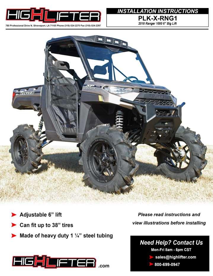
INSTALLATION INSTRUCTIONS *When referring to left and right positions during the installation process, it is from the seated position*
|
|
|
- Griselda McKenzie
- 5 years ago
- Views:
Transcription
1 1

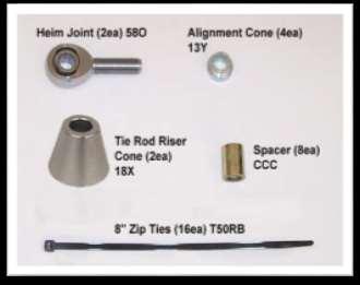
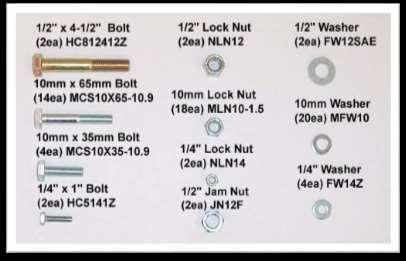
2 PARTS DIAGRAMS 2

3 3
4 4


5 INSTALLATION INSTRUCTIONS *When referring to left and right positions during the installation process, it is from the seated position* FRONT LIFT INSTALLATION 1. Place a jack under the center of the UTV front end until the front wheels clear the ground. Be careful to support it properly so that it is secure, but so that the a-arms and shocks can drop to full extension. NOTE: Make sure that the jack is tall enough to raise the ATV high enough to reinstall the tires after the lift is installed. 2. Remove the front wheels. 3. Disconnect the calipers from the knuckles and the brake lines from the a-arms, but do not disconnect the brake lines from the calipers at this time. Save all the stock hardware to reinstall the calipers. Zip ties are provided to reattach the brake lines to the new a-arms. 4. Remove the cotter pin and castle nut that secure the brake rotor and axle to the hub assembly. 5


6 5. Before removing the upper and lower arms from the front hub assembly. You will first need to disconnect: A. Lower sway bar link end B. Tie rod C. Lower shock end D. Upper Ball joint A B C D 6. Now disconnect the lower ball joint from the knuckle assembly. You will need a 6mm hex key to hold the stud in place while removing the nut. NOTE: You will need to reuse the hardware that connects the hub assembly to the new upper and lower control arms. 6


7 7. Pull the stock axles out of the differential. 8. Disconnect the upper end of the front shocks from the UTV. 9. Unclip the brake lines from the control arms. Tie the calipers up out of the way. 7


8 10. Remove the factory upper and lower control arms from the frame. NOTE: You will need to reuse the factory bolts and nuts that connect the arms to the frame. 11. Repeat the same steps for the other side and make sure both sides of the UTV are completely disassembled. Do this so that the installation will go easier. 12. Next you will need to follow the steps to remove the front sway bar. NOTE: If you have a winch or winch plate, you may have to loosen the bolts or remove it to so you can remove the sway bar. 13. Disconnect the upper end of the sway bar link (and the lower if you haven t already done so). 14. Remove the lock nuts and bolts that attach the bar to the front frame. 8


9 15. Remove the front grill insert to gain access to the sway bar. 16. Slide the sway bar out and through the other end. Then reconnect the front grill insert. 17. Before you prepare to attach the new arms, you need to install the steering stop kit. 18. Start with the driver s side as this has the least amount of room to get your hands in and once you install the spacer on the passenger side you will have less play on the driver s side. 19. Turn the steering wheel all the way to the right. If you are working on the passenger side turn it all the way to the left. NOTE: In order to re-secure the boot you will need to turn the steering wheel closer to the center to give you some play in the boot. 9


.")
10 20. The boots on the rack and pinion are held on by zip ties. You will need to cut the zip tie that secures the boots to the inside of the rack and pinion. Pull the boot back to expose the inner tie rod joint. 21. Place the steering stop clip (10U) between the inner tie rod joint and the rack and pinion. It is a tight fit, so you may have to force it on this is to ensure that the spacer stays in place 22. Pull boot back over the ball joint and steering stop and refasten with an (8 zip tie). Be sure to verify the zip tie is tight so prevent material from getting into the boot. 10


11 23. Before installing the new lower control arms, you will need to remove some material from the inner frame tab nearest to the axle. Remove just enough so the axle can clear the tab when it s at full droop. This is required on both driver and passenger sides. 24. Prepare the new front arms and shocks for installation. 25. You will need to reuse your factory pivot caps, bushings, sleeves, and ball joints. Make sure that you inspect your bushings and ball joints for wear. Replace them as needed. 26. You will need to remove the pivot caps, sleeves, and bushings from the factory arms. NOTE: Take care when removing the bushing from the collars! There is a stop built into the factory arm that prevents the bushing from pushing out when installed. Because of this, the bushing must be pushed out from the opposite side!! A center punch is recommended to remove the bushings. 11


12 27. Remove the ball joints from the STOCK control arms. You will need to reuse these in the new kit. a. Remove snap ring from ball joint. b. Using a press or a vise is suggested for removing and replacing the ball joints. 28. Reinstall ball joints into the NEW control arms. NOTE: A press is suggested for removing and replacing the ball joints. If you press in the ball joint crooked, DO NOT TRY TO FORCE IT IN! If you try to force it straight you can egg the opening. Press the ball joint out and reinsert it into the opening with a press. Verify that the clip snaps into place after installing the ball joints into the new arm. You should always double check the ball joint snap ring for proper fit. Even if you use snap ring pliers, it may not seat. You can use a flathead screwdriver and a hammer to tap the snap ring to ensure that it is seated into the grove. 12


13 29. Now reinstall the bushings, sleeves, and pivot caps into the new arms. If you place some grease on them it makes the installations easier. NOTE: Once the bushing is inserted, you will need to use a socket to help push it in all the way! 30. You will need a spring compressor to install the spring spacers onto the factory shocks. NOTE: The spring spacers are an option. Depending on the ride quality you are wanting, these can be removed if after installation you feel that the quality of the ride is too stiff. We also include steps for adjusting the lift at the shock mounting positions. See step 59! 31. Using a spring compressor, remove the retaining clip and stock spring from the shock. 13
")


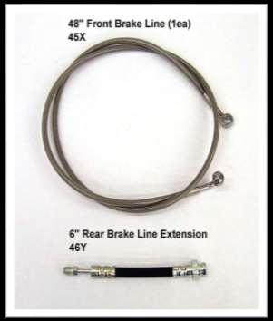
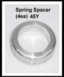
14 32. Next place the spring spacer (45Y) onto the shock. 33. Place spring back on the shock, compress it, and then reinstall the retaining clip. 34. Before you install the new arms and shocks, install the new brake line on the front right passenger side. 14


15 35. Disconnect the brake line from the caliper and free the line from any retaining clips or ties that hold it in place on the right side upper control arm. 36. Next disconnect the line from the master cylinder on the left driver side. Make sure to save the washers from the factory that separate the two front lines. Remove the line from the UTV. 15


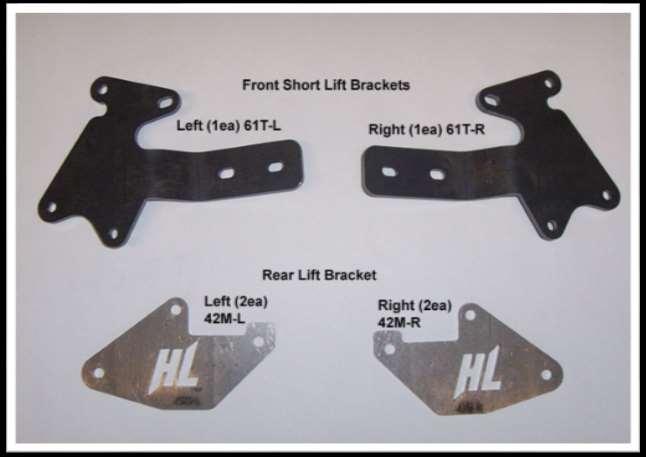
16 37. Now install the new longer 48 brake line (45X) on the right side of the UTV. Run the line back through to the right side front control arm caliper and reconnect it with the factory hardware. 38. Use the existing factory right brake line that you removed to replace the factory left brake line. The factory left line will not be long enough once the new control arms are installed. Then connect all the lines back to the master cylinder using the factory hardware. 39. In the next steps, you are going to install the front lift brackets. 16


17 40. Before you insert the long lift bracket into the center of the UTV, you will need to unclip some wires around the upper shock mount tabs that will be in the way of the installation. 41. When you have unclipped the wires, run the long front lift bracket (61S) behind the wires and along the frame support bars to the other side. You will insert the bracket into the center of the two shock mount tabs on both sides of the UTV when it s ready to bolt on. 17


 and (four 10mm flat washers).")


. 44.")
18 42. Place the left lift bracket (61T-L) to the outside of the front shock mount tab. It needs to be on the side that faces the front of the UTV. Connect the bracket using (two 10x65mm hex bolts) and (four 10mm flat washers). Insert the two bolts through the bracket, then place two washers on each bolt. Insert the bolts through the shock mount tabs. 43. Insert a spacer (CCC) on each of the bolts. Now place the front long lift bracket to the inside of the inner shock mount tab. Push the two bolts all the way through and loosely fasten it with (two 10mm lock nuts). 44. Use (two 10mm x 35mm bolts) to secure the short front lift brackets to the long front lift bracket. 18
 provided. 46.")


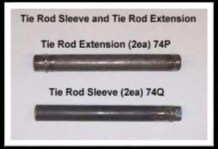
19 45. Insert the bolts from the front to the back and fasten them with the (10mm lock nuts) provided. 46. Do not connect the top of the shock at this time. 47. Repeat the steps for the opposite side. Once both sides are in place, fasten all hardware tight. 48. Next you are going to connect the new tie rod sleeve and tie rod extension to the factory tie rod. NOTE: You may need to clean the paint off the threads of the sleeve and extension before connecting. 49. First remove the factory tie rod end and jam nut. You will not reuse these. 19

 to")


20 50. Slide the tie rod sleeve (74Q) over the factory tie rod and tighten all the way. 51. Attach the tie rod extension (74P) to the factory tie rod and tighten all the way. Note: The right hand side of the rod has a rounded end and the left hand side has an angle cut. The right hand threads will connect the extension to the factory tie rod. The left hand threads will connect the extension to the heim joint. 20
 that will connect to the tie rod")


 first. 55.")
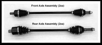
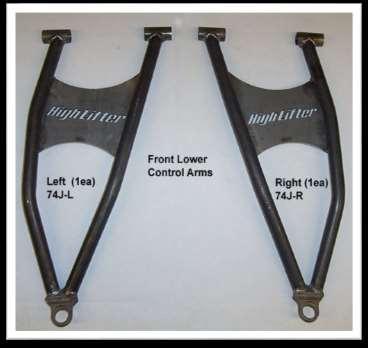
21 52. Provided in the kit is a new heim joint (58O) and (jam nut) that will connect to the tie rod extension. Go ahead and screw the jam nut onto the heim. We recommend that you run the jam nut all the way down the threads and attach to the tie rod extension. This will be adjusted later. 53. Once you have connected the tie rods on both sides, connect the upper and lower control arms. You will use the factory hardware to connect the arms to the frame. 54. Connect the lower control arm (74J-L) first. 55. When you have the lower arm in place, insert the new front axles into the differential. 21


 to the frame")
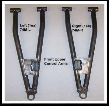
22 56. With the axles in place, reassemble and slide the hub assembly over the axle and connect it to the lower control arm. Use the factory hardware and use the two axle washers and nut provided with the new axle. 57. Torque to factory specs, use a punch and slightly hammer the axle nut at the gap to secure it and prevent it from backing off the threads. 58. Next, connect the upper control arm (74M-L) to the frame and then to the hub assembly. Use the factory hardware. 22


.")
 between the right")
23 59. You have two options for connecting the upper end of the shock to the front lift brackets. By changing the angle of the shocks, you can increase or decrease the stiffness of the ride. If you installed the spring spacers you may want to go with the less lift softer riding position. 60. Now connect the upper portion of the shock to the lift brackets. Insert a (10mm x 65mm bolt) through the bracket and slide on a (10mm washer). Slide the bolt through the shock eyelet. Place another (10mm washer) between the right side of the shock eyelet and bracket. Secure with a (10mm lock nut). 23


 provided in")
24 61. Connect the lower portion of the shock to the new control arm using the factory hardware. 62. Connect the caliper to the hub assembly. Make sure that you reroute the brake lines so that they do not come in contact with moving parts and will not get pinched. Use the (8 zip ties) provided in the kit to secure the brake lines. 24


, and the large cone (18X).")


25 63. Now you will need to connect the tie rod to the hub assembly. You will need to use a ½ drill bit to drill out the factory hole where the original tie rod connected. 64. Once you have drilled the hole, use the (½ x 4-1/2 hex bolt) and the two high alignment bushings, large cone and connect the heim joint to the knuckle. 65. Slide the bolt through the alignment bushing (13Y), the heim, the second alignment bushing (13Y), and the large cone (18X). Then Insert the bolt through the knuckle assembly. 66. Place the (½ washer) and (½ lock nut) on the bolt and torque tight. 67. When you have completed the tie rod installation on both sides you will need to adjust to achieve the proper alignment. Do this before putting the wheels back on. 25
 Take a tape measure and measure from inside to inside on the front and back ends of the rotors. c) They must both be the same distance.")


26 68. Aligning the front wheels: a) Make sure that the brake rotors are straight to sight. b) Take a tape measure and measure from inside to inside on the front and back ends of the rotors. c) They must both be the same distance. If they do not then you will need to adjust the tie rods in or out. This is setting the toe to zero. NOTE: A slight toe out makes the steering less sensitive and the UTV more stable. When adjusting the toe, be sure to take the time to adjust both ends half the required distance. 69. When you have achieved your desired setting, lock the tie rod in place with the jam nut. 70. Once you have done these steps, place the tires back on the ATV and torque lugs to factory specifications. 71. Make sure to check all nuts and bolts to ensure that they are all tight before you proceed to the rear installation. REAR LIFT INSTALLATION 72. Place a jack under the center of the UTV rear end until the rear wheels clear the ground. Be careful to support it properly so that it is secure, but so that the a-arms and shocks can drop to full extension. NOTE: Make sure that the jack is tall enough to raise the ATV high enough to reinstall the tires after the lift is installed. 73. Remove the rear wheels. 74. Disconnect the brake caliper from the hub assembly, leaving the brake line attached to the caliper. Unclip the brake line from the lower control arm and secure the caliper out of the way so it does not interfere with the installation process. 26


27 75. Disconnect and remove the factory cotter pin and castle nut on the rear axles. Then remove the brake rotor assembly. 76. Disconnect the upper and lower control arms from the hub assembly and remove the hub assembly. And disconnect the lower end of the rear shock. 27


28 77. Remove the nuts that secure the sway bar to the sway bar rod. You will completely remove the sway bar, sway bar connecting brackets, and rods from the UTV. They are not used in conjunction with the big lift kit. 78. Unclip all brake lines from the control arms. You will need to use a drill bit to drill out the factory p-clamps until they snap off. Remove the clamps. 28


29 79. Disconnect the rear shock from the upper frame and control arms. 80. Pull the stock axles out of the differential. 81. Remove the upper and lower rear control arms from the UTV. You will reuse the factory hardware to reconnect the new control arms to the frame. 82. At this time it will be easier for you to extend the brake line. Included in the kit is a 6 brake line extension for the rear left side. 83. Locate the brake line junction fitting on the rear lower left side of the frame. 84. Disconnect the brake line from the junction fitting. Connect the new 6 extension (46Y) to the brake line at this time. 29


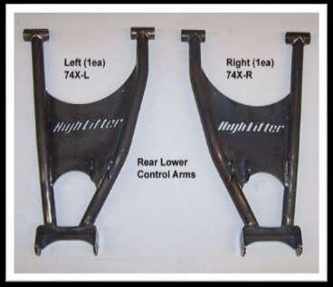
30 85. Reconnect the new brake extension lines to the brake line junction. You may need to do some re-routing at a later point to ensure that there is no pinching of the brake lines. 86. Now prepare the new arms for installation. 87. You will need to reuse your factory bushings and sleeves. Make sure that you inspect your bushings for wear. Replace them as needed. Repeat steps used previously on the front arms. 88. Once you have removed the stock bushings and sleeves from the factory arms, install them into the new arms in the kit. If you place some grease on them it makes the installation easier. 89. You will need a spring compressor to install the spring spacers onto the factory shocks. Repeat steps used previously on the front shocks. 90. When you have prepared the arms, it s time to install. For the rear it will be best to start from the bottom and work your way up to the top. 91. Install the new max clearance lower control arm (74X-L) to the frame, using the factory hardware. 30


 to the")


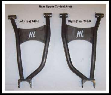
31 92. Next install the rear axles into the differential. 93. Install the new max clearance upper control arm (74S-L) to the frame, using the factory hardware. 94. Now, slide the hub assembly over the axle end. Connect the upper and lower arms to the hub assembly using the factory hardware. 95. Place the rotor onto the hub and axle assembly. Fasten the rotor using the 3 axle washers, castle nut, and cotter pin provided in the kit. 31


.")

32 96. Repeat steps for the opposite side. 97. Next, install the rear upper lift brackets. There are left and right plates. From the rear, the logo should read from left to right. 98. Place the one rear lift bracket (42M-L) to the outside of the rear shock mount. It needs to be on the side that faces the front of the UTV. Connect the bracket using (two 10x65mm hex bolts). Place (two 10mm washers) on each bolt then insert the two bolts through the bracket. Insert the bolts through the shock mount tabs. 99. Now insert a spacer (CCC) on each of the bolts and the other rear lift bracket to the inside of the outer shock mount tab. Loosely fasten it with (two 10mm lock nuts). 32
 and (10mm")


 and (10mm lock nut)")

33 100. Connect the top of the shock to the lift brackets using one (10x65mm hex bolt) and (10mm lock nut). Once all the bolts are in place fasten them tight. Repeat the steps for the opposite side Connect the lower portion of the shock to the control arm. Us the (10mm x 65mm bolt) and (10mm lock nut) provided Fasten the caliper to the hub assembly Make sure that you run the brake lines in a manner that they do not come in contact with moving parts and they do not become pinched. 33
 provided. 105.")


34 104. Fasten and secure the left rear brake line to the upper control arm using the (8 zip ties) provided For the right rear factory brake line. You will need to pull the slack out from where the line runs under the rear differential. Make sure the line is still running through the two clamps attached to the bottom and clear from touching the rear drive shaft Now fasten and secure the line to the upper arm using the (8 zip ties) provided. 34

 between the frame bracket and the bed.")
 and (1/4 lock nut). Reconnect the wire. 110.")


 When the steering is zeroed, check the steering wheel to make")
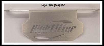
35 107. Once you have completed both sides place the wheels back on the Ranger and torque lugs to factory specifications Install the rear logo plate Lift the bed up to gain access to the rear frame bracket. Disconnect and unclip the wire. Slide the logo plate (61Z) between the frame bracket and the bed. Slide a (1/4 x 1 bolt) and (1/4 washer) through the logo plate and into each hole on the frame. Fasten the bolts with a (1/4 washer) and (1/4 lock nut). Reconnect the wire You may need to check the factory steering. NOTE: The steering from the factory for the Polaris Ranger 1000 may not be centered. This can cause the tie rod ends to have more engagement on one side and less on the other. This also causes the steering wheel to not be centered. If your steering is already centered then you WILL NOT have to follow these next steps Setting the steering to ZERO: a) When the steering is zeroed, check the steering wheel to make sure that it is properly positioned or not. If the steering wheel is not centered, you will need to remove the center cap with a flat head screwdriver to gain access to the steering wheel nut. 35

 Once you break free and loosen the nut.")


 Now will be the time to adjust the steering wheel accordingly.")

36 b) Using a ratchet, turn the steering nut counter clockwise. Continue this until the steering wheel locks at full turn, and then loosen the nut. Do not remove the nut yet. c) Once you break free and loosen the nut. Back it off just enough leaving a few threads left. Next, take a hammer and tap on the nut while pulling up on the steering wheel until it breaks loose. But DO NOT hammer too hard, it could damage the nut or threads. Now remove the nut and steering wheel. NOTE: You may need a puller to remove the steering wheel if you can t break the wheel free with a hammer. d) Now will be the time to adjust the steering wheel accordingly. Replace the wheel and make sure the wheels are turned back straight. The steering wheel should be straight up and down. NOTE: Rolling vehicle back and forth may help straighten the wheels. e) Now thread back on the steering wheel nut. Turn the nut clockwise until the steering wheel locks at full turn, and tighten the nut. Then replace the center cap. NOTE: You may want to apply loctite to the nut. 36

37 This product has a dual warranty. The suspension components have a life time warranty and the axles have a limited replacement. Please see information on the following pages. 37
38 Read before Installation This product is designed for use on RUVs for extreme mud riding conditions. Purchasers should be aware that use of this product will increase the frequency of required maintenance, part wear, will raise the center of gravity on your RUV, will increase stopping distance, will decrease turning radius and will increase risk of roll-over, injury and death on all types of terrain. It is your responsibility to always inform other operators and passengers of this vehicle and about the added risks. Adding or modifying any OEM or aftermarket part will usually void factory warranty. This product could interfere with other aftermarket accessories. If the user has aftermarket products on machine, contact High Lifter Products to verify that they will work together. It is up to the end user or installer to verify this product works in conjunction with all other accessories installed. Adding aftermarket suspension components and/or more aggressive tires can cause breakage of other OEM driveline components such as differentials, axles or drive shafts. We recommend that wider tires and/or wheel spacers be used to achieve a wider stance and to improve stability of the RUV. Riders should be advised that the handling characteristics of a taller ATV or RUV are different and require extra care when riding, particularly on side hills, off-camber situations, turning and stopping. If you further raise the center of gravity by adding taller tires, heavy loads, or by any other means, the RUV must be operated with even more care, at slower speeds and on relatively flat ground. All turns should be done at a slow speed, even on level ground. Operation of an RUV with or without modified suspension components, while or shortly after consuming alcohol or drugs, subjects the rider to the risk of serious bodily harm or possible death. This risk is compounded if the rider does not wear an approved helmet and other safety gear. High Lifter urges that all approved safety gear be worn when riding an RUV as a driver or passenger. By purchasing and installing this product, user agrees that should damages occur, High Lifter Products will not be held responsible for loss of time, use, labor fees, replacement parts, or freight charges. High Lifter Products will not be held responsible for any direct, indirect, incidental, special, or consequential damages that result from any product purchased from High Lifter Products. The total liability of seller to user for all damages, losses, and causes of action, shall not exceed the total purchase price paid for the product that gives rise to the claim. Since this is an extreme product, the manufacturer specifically disclaims any liability for consequential damages or accidents injuries, or death, in connections with the use of this product. If this product is not what you expected, or is not consistent with your intended use, you should return the product immediately to the seller, before installation, for a refund of the purchase price; less any fees. After installation, product is warranted to the original user and vehicle for the life of that vehicle for defects in workmanship and materials. Axles have a one year warranty for one break. Additional breaks will be charged a repair fee depending on the problem. High Lifter Products will warranty only parts provided by High Lifter Products. Any damage or problems with OEM housings, bearings, seals, or other manufacturer s products will not be covered by High Lifter Products. Parts and products will not be warranted if item was not installed properly, misused, or modified. Dealers and other Installers You are responsible for informing your customer and end user of the information contained above and the increased potential hazards of operating an RUV equipped with modified suspension components. If you install any suspension modifying components, it is your responsibility to also install the warning label prominently in view of the driver and passenger. They should also be instructed to notify anyone operating the vehicle, as well as any passengers, that said vehicle is modified. As discussed above, it is critically important that they be instructed in the need for slower speed operation, regardless of terrain, after this kit is installed. 38
39 High Lifter Outlaw RCV Big Lift Axle Warranty Program Thank you for purchasing a High Lifter Products Big Lift equipped with a set of Outlaw RCV Big Lift Axles. Our axles have been engineered to provide superior performance for use on your ATV/UTV. LIMITED WARRANTY: HIGH LIFTER PRODUCTS, INC. warrants to the ORIGINAL purchaser of any High Lifter Big Lift Equipped with 4-Outlaw RCV Big Lift Axles for a total of one (1) axle warranty claim or breakage Per set of 4 axles (not (1) warranty claim or breakage for each individual axle) for a period of one (1) year from the original date of purchase. This warranty covers defects in materials or workmanship or failures in normal services. Repair services will be available after the warranty has expired for an additional cost (repair costs will be determined by the actual components that need to be replaced). If you need repair service for your Outlaw RCV axle please contact your High Lifter representative at for an estimate. The limited warranty is subject to the following conditions: a) The product is properly installed. b) HIGH LIFTER is not liable for any incidental or consequential damages to anything other than the axle covered by this warranty, including labor costs to remove/reinstall, loss of use of machine, damage to housings, or damage to OEM supplied parts. c) If the axle has been disassembled or modified by a third party, or has OEM parts installed on the axle, the warranty is null and void. d) Any axle damaged in a collision is excluded from this warranty. However, they may be refurbished for standard costs pending authorization by the owner. e) Warranty is non-transferable from the ORIGINAL purchaser. f) HIGH LIFTER reserves the right to inspect the axle and determine any defects in installation to determine the validity of a warranty s claim. This may include the ORIGINAL purchaser providing photographs of the ATV/UTV and its installed lift kit. g) Boots damaged by CV joint failures are covered under this warranty. Boots damaged by punctures or tears from trail obstructions are not covered under this warranty. Boot inspection should be a part of regular ATV/UTV maintenance. REFUSED SHIPMENTS/ORDER CANCELLATION: Refused shipments are subject to a 25% restocking fee plus return freight. If a customer wishes to cancel an order (provided it is not a special order product), it is the responsibility of the customer to cancel the order prior to the product being shipped. If a customer cancels an order after product has been shipped, the refused shipment, cancellation, or return will be subject to a 25% restocking fee and any freight charges incurred. For orders outside the United States, any fees associated with customs or duties are non refundable. DAMAGED SHIPMENTS: All claims for damaged shipments must be made within 72 hours of delivery to the point of destination. Any damage to package should be noted with carrier at the time of delivery if possible. We will not be responsible for damage claims made over 72 hours after delivery to the point of destination. OBTAINING A WARRANTY CLAIM: All returns for warranty must be pre-approved by calling After warranty approval has been granted and a Return Merchandise Authorization (RMA) number issued, the axle must be received by HIGH LIFTER PRODUCTS within 15 calendar days. The RMA number must be clearly displayed on the return box or the return will be refused. An RMA number does not imply a replacement or refund on any product, but only that we will inspect the axle for warranty claims. For orders outside the United States, any fees associated with customs or duties are non-refundable. All claims must be accompanied by the sales receipt detailing date and place of purchase, a written explanation of the problem, a phone number, and address. A copy of this receipt must be included with the axle submitted for warranty repair or replacement. The purchaser is responsible for any freight charges on a warranty claim or repair service after the warranty expires, including incoming freight to High Lifter and return freight to the purchaser. 39

40 High Lifter Lifetime Warranty From the beginning, High Lifter has engineered and manufactured some of the toughest, most durable products on the market. That s why this product comes with a Lifetime Warranty. It s our promise that High Lifter will never let you down. The Lifetime Warranty covers products sold to the original purchaser only and is not transferable. The term of the warranty is for the lifetime of the vehicle in question. Normal wear and tear items and finishes, such as, but not limited to: Heim joints, tie rod ends, ball joints, bearings, seals, bushings, bushing sleeves, zinc plating, powder coating, or chipping and discoloration of any finish is not covered. High Lifter will ship the replacement product after the returned product has been inspected by High Lifter staff. The warranty shall not include claims for damages, installation time or labor charges, economic losses, inconvenience, transportation, towing, down time, direct or indirect or consequential damages or delay resulting from any defect. The warranty does not apply to products that have been improperly applied or improperly installed. Making a warranty claim 1. All claims must be accompanied by the part and the original sales receipt or other acceptable proof of purchase from the original owner. 2. All warranties must be accompanied with a Return Merchandise Authorization (RMA) number. (Contact High Lifter at or for an RMA number) 3. When shipping the damaged product: a. Write the RMA number on the outside of the box. b. Also include the RMA number, proof of purchase and any notes inside the box. c. Please keep your tracking number and shipment information. 4. The customer is responsible for shipping the product to High Lifter--return shipping within the lower 48 states will be paid by High Lifter products. With all warranty claims, only standard shipping services apply. 5. High Lifter will process your order within 24 business hours of receiving the returned item. 6. Ship to: High Lifter Products, 780 Professional Drive North, Shreveport, Louisiana For axle warranty see additional information sheet! 40
2. Remove front wheels.
 1 PARTS DIAGRAM 2 Installation Instructions: (PASSENGER SIDE) 1. Place jack under center of RUV front end and lift until front wheels clear the ground. Be careful to support the RUV properly so that it
It is your responsibility to always inform other operators and passengers of this vehicle and about the added risks.
 780 Professional Drive N. Shreveport, LA 71105 Phone (318)-524-2270 Fax (318)-524-2297 www.highlifter.com Read before Installation This product is designed for use on RUVs for extreme mud riding conditions.
4. Remove the cotter pin that secures the castle nut to the axle. Once you have done this remove the castle nut and pull off the hub/rotor assembly.
 780 Professional Drive N. Shreveport, LA 71105 Phone (318)-524-2270 Fax (318)-524-2297 Max Clearance Honda Pioneer 1000 Front Forward Arched Control Arm Kit Read before Installation This product is designed
NOTE: IF RUNNING FACTORY RANGER ALUMINUM WHEELS OR AFTERMARKET ALUMINUM WHEELS THEN SPACERS ARE NOT REQUIRED.
 780 Professional Dr. North, Shreveport, LA. 318-524-2270 Polaris Ranger Lift Kit Installation Instructions PLK1000R-51 Read before Installation This product is designed for use on ATVs and/or RUVs to increase
780 Professional Drive N. Shreveport, LA Phone (318) Fax (318) Lift Kit Installation Instructions
 Fax (318) Lift Kit Installation Instructions") 780 Professional Drive N. Shreveport, LA 71105 Phone (318)-524-2270 Fax (318)-524-2297 www.highlifter.com Polaris Mid-Size 570 RANGER Models Lift Kit Installation Instructions Read before Installation
780 Professional Drive N. Shreveport, LA 71105 Phone (318)-524-2270 Fax (318)-524-2297 www.highlifter.com Polaris Mid-Size 570 RANGER Models Lift Kit Installation Instructions Read before Installation
NOTE: IF RUNNING FACTORY RANGER 900 ALUMINUM WHEELS OR AFTERMARKET ALUMINUM WHEELS THEN SPACERS ARE NOT REQUIRED.
 780 Professional Dr. North, Shreveport, LA. 318-524-2270 Polaris 900 XP Ranger Lift Kit Installation Instructions Read before Installation This product is designed for use on ATVs and/or RUVs to increase
780 Professional Drive N. Shreveport, LA Phone (318) Fax (318) Kawasaki Teryx 4-Seater
 Fax (318) Kawasaki Teryx 4-Seater") 780 Professional Drive N. Shreveport, LA 71105 Phone (318)-524-2270 Fax (318)-524-2297 Kawasaki Teryx 4-Seater Read before Installation This product is designed for use on ATVs and/or RUVs to increase
780 Professional Drive N. Shreveport, LA 71105 Phone (318)-524-2270 Fax (318)-524-2297 Kawasaki Teryx 4-Seater Read before Installation This product is designed for use on ATVs and/or RUVs to increase
Max Clearance Polaris RZR 900 S 60 Rear Lower Arched Control Arm Kit
 780 Professional Drive N. Shreveport, LA 71105 Phone (318)-524-2270 Fax (318)-524-2297 Max Clearance Polaris RZR 900 S 60 Rear Lower Arched Control Arm Kit Read before Installation This product is designed
780 Professional Drive N. Shreveport, LA Phone (318) Fax (318)
 Fax (318)") 780 Professional Drive N. Shreveport, LA 71105 Phone (318)-524-2270 Fax (318)-524-2297 www.highlifter.com Polaris RZR 570 Lift Kit Installation Instructions Read before Installation This product is designed
780 Professional Drive N. Shreveport, LA 71105 Phone (318)-524-2270 Fax (318)-524-2297 www.highlifter.com Polaris RZR 570 Lift Kit Installation Instructions Read before Installation This product is designed
(318) (318) & 800 RANGER IRS
 (318) & 800 RANGER IRS") 780 Professional Drive N. Shreveport, LA 71105 Phone (318)-524-2270 Fax (318)-524-2297 Polaris 700 & 800 RANGER IRS Models Lift Kit Installation Instructions Read before Installation This product is designed
780 Professional Drive N. Shreveport, LA 71105 Phone (318)-524-2270 Fax (318)-524-2297 Polaris 700 & 800 RANGER IRS Models Lift Kit Installation Instructions Read before Installation This product is designed
780 Professional Dr. North, Shreveport, LA Polaris Ranger Lift Kit Installation Instructions CLKCMX3-02
 780 Professional Dr. North, Shreveport, LA. 318-524-2270 Polaris Ranger Lift Kit Installation Instructions CLKCMX3-02 Read before Installation This product is designed for use on ATVs and/or RUVs to increase
FRONT LIFT INSTALLATION *When referring to left and right positions during the installation process, it is from the seated position*
 1 Parts Diagram 2 FRONT LIFT INSTALLATION *When referring to left and right positions during the installation process, it is from the seated position* 1. Place UTV transmission in park. Place jack under
Max Clearance Polaris Sportsman Arched A-arm Kit
 780 Professional Drive N. Shreveport, LA 71105 Phone (318)-524-2270 Fax (318)-524-2297 Max Clearance Polaris Sportsman Arched A-arm Kit Read before Installation This product is designed for use on ATVs
780 Professional Drive N. Shreveport, LA Phone (318) Fax (318) Suzuki King Quad 750/500Lift Kit Installation Instructions
 Fax (318) Suzuki King Quad 750/500Lift Kit Installation Instructions") 780 Professional Drive N. Shreveport, LA 71105 Phone (318)-524-2270 Fax (318)-524-2297 Suzuki King Quad 750/500Lift Kit Installation Instructions Read before Installation This product is designed for use
780 Professional Drive N. Shreveport, LA 71105 Phone (318)-524-2270 Fax (318)-524-2297 Suzuki King Quad 750/500Lift Kit Installation Instructions Read before Installation This product is designed for use
780 Professional Drive N Shreveport, LA Phone (318) Polaris Ranger RZR 1000 XP Upper Radius Bars
 Polaris Ranger RZR 1000 XP Upper Radius Bars") 780 Professional Drive N Shreveport, LA 71105 Phone (318)524-2270 Polaris Ranger RZR 1000 XP Upper Radius Bars Read before Installation This product is designed for use on ATVs and/or RUVs to increase
780 Professional Drive N Shreveport, LA 71105 Phone (318)524-2270 Polaris Ranger RZR 1000 XP Upper Radius Bars Read before Installation This product is designed for use on ATVs and/or RUVs to increase
Max Clearance Honda Front Lower Arched Control Arm Kit
 780 Professional Drive N. Shreveport, LA 71105 Phone (318)-524-2270 Fax (318)-524-2297 Max Clearance Honda Front Lower Arched Control Arm Kit Read before Installation This product is designed for use on
Honda 700 Pioneer Lift Kit
 780 Professional Drive N. Shreveport, LA 71105 Phone (318)-524-2270 Fax (318)-524-2297 www.highlifter.com Honda 700 Pioneer Lift Kit Read before Installation This product is designed for use on ATVs and/or
780 Professional Drive N. Shreveport, LA Phone (318) Fax (318) Lift Kit Installation Instructions
 Fax (318) Lift Kit Installation Instructions") 780 Professional Drive N. Shreveport, LA 71105 Phone (318)-524-2270 Fax (318)-524-2297 Yamaha Grizzly 700 Lift Kit Lift Kit Installation Instructions Read before Installation This product is designed for
780 Professional Drive N. Shreveport, LA 71105 Phone (318)-524-2270 Fax (318)-524-2297 Yamaha Grizzly 700 Lift Kit Lift Kit Installation Instructions Read before Installation This product is designed for
780 Professional Drive N. Shreveport, LA Phone (318) Fax (318) Honda Lift Kit Installation Instructions
 Fax (318) Honda Lift Kit Installation Instructions") 780 Professional Drive N. Shreveport, LA 71105 Phone (318)-524-2270 Fax (318)-524-2297 www.highlifter.com Honda Lift Kit Installation Instructions Read before Installation This product is designed for
780 Professional Drive N. Shreveport, LA 71105 Phone (318)-524-2270 Fax (318)-524-2297 www.highlifter.com Honda Lift Kit Installation Instructions Read before Installation This product is designed for
Polaris Ranger RZR 1000 XP Radius Bars PSRA-RZR1
 780 Professional Drive N Shreveport, LA 71105 Phone (318)524-2270 Polaris Ranger RZR 1000 XP Radius Bars PSRA-RZR1 Read before Installation This product is designed for use on ATVs and/or RUVs to increase
780 Professional Drive N. Shreveport, LA Phone (318) Fax (318) Kawasaki Mule Pro FXT
 Fax (318) Kawasaki Mule Pro FXT") 780 Professional Drive N. Shreveport, LA 71105 Phone (318)-524-2270 Fax (318)-524-2297 www.highlifter.com Kawasaki Mule Pro FXT Read before Installation This product is designed for use on ATVs and/or
780 Professional Drive N. Shreveport, LA 71105 Phone (318)-524-2270 Fax (318)-524-2297 www.highlifter.com Kawasaki Mule Pro FXT Read before Installation This product is designed for use on ATVs and/or
780 Professional Drive N. Shreveport, LA Phone (318) Fax (318) Honda 420 Installation Instructions
 Fax (318) Honda 420 Installation Instructions") 780 Professional Drive N. Shreveport, LA 71105 Phone (318)-524-2270 Fax (318)-524-2297 www.highlifter.com Honda 420 Installation Instructions Read before Installation This product is designed for use on
780 Professional Drive N. Shreveport, LA 71105 Phone (318)-524-2270 Fax (318)-524-2297 www.highlifter.com Honda 420 Installation Instructions Read before Installation This product is designed for use on
780 Professional Drive N. Shreveport, LA Phone (318) Fax (318)
 Fax (318)") 780 Professional Drive N. Shreveport, LA 71105 Phone (318)-524-2270 Fax (318)-524-2297 www.highlifter.com KLKM610-00 Read before Installation This product is designed for use on ATVs and/or RUVs to increase
780 Professional Drive N. Shreveport, LA 71105 Phone (318)-524-2270 Fax (318)-524-2297 www.highlifter.com KLKM610-00 Read before Installation This product is designed for use on ATVs and/or RUVs to increase
780 Professional Drive N. Shreveport, LA Phone (318) Fax (318) Polaris RZR TURBO XP
 Fax (318) Polaris RZR TURBO XP") 780 Professional Drive N. Shreveport, LA 71105 Phone (318)-524-2270 Fax (318)-524-2297 www.highlifter.com Polaris RZR TURBO XP Read before Installation This product is designed for use on ATVs and/or RUVs
780 Professional Drive N. Shreveport, LA 71105 Phone (318)-524-2270 Fax (318)-524-2297 www.highlifter.com Polaris RZR TURBO XP Read before Installation This product is designed for use on ATVs and/or RUVs
780 Professional Drive N. Shreveport, LA Phone (318) Fax (318)
 Fax (318)") 780 Professional Drive N. Shreveport, LA 71105 Phone (318)-524-2270 Fax (318)-524-2297 Yamaha YXZ 1000 Lift Kit Installation Instructions Read before Installation This product is designed for use on ATVs
780 Professional Drive N. Shreveport, LA 71105 Phone (318)-524-2270 Fax (318)-524-2297 Yamaha YXZ 1000 Lift Kit Installation Instructions Read before Installation This product is designed for use on ATVs
SPORTSMAN 800/500 INSTALLATION NOTES FOR 2011 MODELS:
 780 Professional Drive N Shreveport, LA 71105 Phone: 318-524-2270 Polaris Sportsman Lift Kit Read before Installation This product is designed for use on ATVs and/or RUVs to increase ground clearance and
780 Professional Drive N. Shreveport, LA Phone (318) Fax (318) KLKM
 Fax (318) KLKM") 780 Professional Drive N. Shreveport, LA 71105 Phone (318)-524-2270 Fax (318)-524-2297 www.highlifter.com KLKM3000-00 Read before Installation This product is designed for use on ATVs and/or RUVs to increase
780 Professional Drive N. Shreveport, LA 71105 Phone (318)-524-2270 Fax (318)-524-2297 www.highlifter.com KLKM3000-00 Read before Installation This product is designed for use on ATVs and/or RUVs to increase
It is your responsibility to always inform other operators and passengers of this vehicle and about the added risks.
 780 Professional Drive N. Shreveport, LA 71105 Phone (318)-524-2270 Fax (318)-524-2297 www.highlifter.com Read before Installation This product is designed for use on RUVs for extreme mud riding conditions.
It is your responsibility to always inform other operators and passengers of this vehicle and about the added risks.
 780 Professional Drive N. Shreveport, LA 71105 Phone (318)-524-2270 Fax (318)-524-2297 www.highlifter.com Read before Installation This product is designed for use on ATVs and/or RUVs for extreme mud riding
Max Clearance Arctic Cat Forward Front Upper & Lower Arched Control Arm Kit
 780 Professional Drive N. Shreveport, LA 71105 Phone (318)-524-2270 Fax (318)-524-2297 Max Clearance Arctic Cat Forward Front Upper & Lower Arched Control Arm Kit The Max Clearance Control Arm Kit is designed
Suzuki 500 (98+) Lift Kit Installation Instructions
 Lift Kit Installation Instructions") 780 Professional Drive N. Shreveport, LA 71105 Phone (318)-524-2270 Fax (318)-524-2297 www.highlifter.com Suzuki 500 (98+) Lift Kit Installation Instructions Read before Installation This product is designed
780 Professional Drive N. Shreveport, LA 71105 Phone (318)-524-2270 Fax (318)-524-2297 www.highlifter.com Suzuki 500 (98+) Lift Kit Installation Instructions Read before Installation This product is designed
780 Professional Drive N. Shreveport, LA Phone (318) Fax (318)
 Fax (318)") 780 Professional Drive N. Shreveport, LA 71105 Phone (318)-524-2270 Fax (318)-524-2297 Read before Installation This product is designed for use on ATVs and/or RUVs for extreme mud riding conditions. Purchasers
780 Professional Drive N. Shreveport, LA 71105 Phone (318)-524-2270 Fax (318)-524-2297 Read before Installation This product is designed for use on ATVs and/or RUVs for extreme mud riding conditions. Purchasers
High Lifter Products, Inc.
 High Lifter Products, Inc. Phone 318-524-2270 780 N Professional Dr Fax 318-524-2297 Shreveport, LA 71105 www.highlifter.com Proseries Polaris Forward A-arm Kit The Proseries A-arm kit is designed to permit
Max Clearance Polaris Ranger 900 XP Front Forward Arched Control Arm Kit
 780 Professional Drive N. Shreveport, LA 71105 Phone (318)-524-2270 Fax (318)-524-2297 Max Clearance Polaris Ranger 900 XP Front Forward Arched Control Arm Kit The Max Clearance Control Arm Kit is designed
This lift allows you to convert from lifted to unlifted positions!
 780 Professional Drive N. Shreveport, LA 71105 Phone (318)-524-2270 Fax (318)-524-2297 Polaris Ranger RZR 900 XP This lift allows you to convert from lifted to unlifted positions! Read Before Installation
Polaris RZR 900 XP Arched Trailing Arms PSATA-RZR9
 780 Professional Drive N Shreveport, LA 71105 Phone (318)524-2270 Polaris RZR 900 XP Arched Trailing Arms PSATA-RZR9 Read Before Installation This product is designed for use on ATVs and/or RUVs to increase
Arctic Cat Wild Cat Upper Radius Bars
 780 Professional Drive N Shreveport, LA 71105 Phone (318)524-2270 Arctic Cat Wild Cat Upper Radius Bars Read Before Installation This product is designed for use on ATVs and/or RUVs to increase ground
PARTS DIAGRAM INSTALLATION INSTRUCTIONS
 SBLK-RZR1-R 1 PARTS DIAGRAM INSTALLATION INSTRUCTIONS (LH) - LEFT HAND (RH) - RIGHT HAND 1. First, you need to preassemble the new heavy duty High Lifter sway bar link. 2. If not already done, fasten the
Suzuki 700 Lift Kit Lift Kit Installation Instructions
 High Lifter Products, Inc. 318-524-2270 780 N Professional Drive 318-524-2297 Shreveport, LA 71105 Suzuki 700 Lift Kit Lift Kit Installation Instructions Read Before Installation This product is designed
6 Lift Kit - Kawasaki Teryx4
 2753 Michigan Road Madison, Indiana 47250 855-743-3427 INSTALLATION INSTRUCTIONS 6 Lift Kit - Kawasaki Teryx4 1 Spacers are required if running stock Wheels Driver C A D B Passenger Item Description A
SPECIAL TOOLS REQUIRED:
 INSTALLATION INSTRUCTIONS FOR 2010-15 TOYOTA 4RUNNER WITH XREAS SUSPENSION 3 SUSPENSION LIFT KIT PART NUMBER 432X WARNING!!! READ AND UNDERSTAND ALL INSTRUCTIONS BEFORE PROCEEDING. MAKE SURE THAT YOU HAVE
Gen 2 Portal Gear Hubs for Polaris Ranger Crew 570/900
 2753 Michigan Road Madison, Indiana 47250 855-743-3427 INSTALLATION INSTRUCTIONS Gen 2 Portal Gear Hubs for Polaris Ranger Crew 570/900 A Item Description Qty A Rotor 4 B Gear Box, L 2 C Gear Box, R 2
Verify, and adjust if necessary, centering of Rack and Pinion before installing.
 Verify, and adjust if necessary, centering of before installing. measurement 1: face of Tie Rod End inside of 1. Measure distance from inside of Rack and Pinion to face of Tie Rod End. 2. Measure distance
INSTALLATION INSTRUCTIONS FOR FORD 4WD SUPER DUTY F /2 COIL SPRING SUSPENSION SYSTEM
 INSTALLATION INSTRUCTIONS FOR 2005-07 FORD 4WD SUPER DUTY F250-350 4 1/2 COIL SPRING SUSPENSION SYSTEM Requires the following parts (sold separately) for a complete installation: KIT PART NUMBER (6345
3 Lift Kit: for Polaris General
 INSTALLATION INSTRUTIONS 740B lifty Drive Madison, Indiana 47250 812-574-7777 3 Lift Kit: for Polaris General Item Description Qty A Rear Shock Bracket Brace 1 B Shock Bracket 1 Rear Shock Bracket 2 D
FRONT DRIVELINE MODIFICATION MAY BE NECESSARY!!!!
 INSTALLATION INSTRUCTIONS FOR 2009 DODGE 2500/3500 4WD & 1500 Mega Cab 6 SUSPENSION SYSTEM PART NUMBER 7206 Requires the following parts (sold separately) for a complete installation: Front Coil Spring
" CHEVY / GMC WD BASIC KIT
 84302 2007-2013 6" CHEVY / GMC 1500 4WD BASIC KIT 100% Bolt On 6 Spindle Kit Front Differential Is Dropped A Full 6 To Maintain Proper CV Axle Angles Impact Struts To Distribute Front Suspension Impact
INSTALLATION INSTRUCTIONS FOR FORD 4WD SUPER DUTY F COIL SPRING SUSPENSION SYSTEM
 INSTALLATION INSTRUCTIONS FOR 2008-10 FORD 4WD SUPER DUTY F250-350 6 COIL SPRING SUSPENSION SYSTEM Requires the following parts (sold separately) for a complete installation: KIT PART NUMBER (6860) REQUIRES
3 Lift Kit: for Polaris General
 INSTALLATION INSTRUCTIONS 2753 Michigan Road Madison, Indiana 47250 855-743-3427 3 Lift Kit: for Polaris General Item Description Qty A Rear Shock Bracket Brace 1 B Front Shock Bracket 1 C Rear Shock Bracket
Installation manual. Toyota Tundra 4WD & 2WD. 2.5 Suspension kit. Part # Part # Important customer information:
 Installation manual 2007-2016 Toyota Tundra 4WD & 2WD 2.5 Suspension kit Part # 53070 sj11082011rev.03 Part # 53070 2007-2016 Toyota Tundra 4WD & 2WD 2.5 Suspension kit Part # Description Qty. 53070-01
Verify, and adjust if necessary, centering of Rack and Pinion before installing.
 Verify, and adjust if necessary, centering of Rack and Pinion before installing. 1. Measure distance from inside of Rack and Pinion to face of Tie Rod End. 2. Measure distance from face of Tie Rod End
CHEVY / GMC 1500HD / 2500HD 2WD 8 LUG 7 BASIC KIT
 85101 2000-2010 CHEVY / GMC 1500HD / 2500HD 2WD 8 LUG 7 BASIC KIT C8510-4 MAIN BOX KIT W/ HARDWARE 1) FRONT X MEMBER 1) REAR X MEMBER 2) TORSION BAR DROPS 1) LEFT BUMP STOP 1) RIGHT BUMP STOP 2) SWAY BAR
PARTS LIST INCLUDED IN KIT TORQUE SPECIFICATIONS PRODUCT SAFETY LABEL MUST BE INSTALLED INSIDE CAB IN PLAIN VIEW OF ALL OCCUPANTS.
 INSTALLATION INSTRUCTIONS FOR 2010-15 TOYOTA 4RUNNER SR5 AND SPORT (Non-Air Leveling & Non-X-REAS) AND FOR 2010-14 TOYOTA FJ CRUISER 2WD & 4WD 3 SUSPENSION LIFT KIT PART NUMBER 432 WARNING!!! READ AND
WARNING!!! READ AND UNDERSTAND ALL INSTRUCTIONS BEFORE PROCEEDING. MAKE SURE THAT YOU HAVE ALL TOOLS AND PARTS BEFORE BEGINNING THE INSTALLATION.
 INSTALLATION INSTRUCTIONS FOR 2005-2015 TOYOTA TACOMA 4 X 4 AND PRERUNNER, 2003-2015 4RUNNER, 2007-2014 FJ CRUISER 1.5" FRONT LEVELING KIT PART NUMBER 415 WARNING!!! READ AND UNDERSTAND ALL INSTRUCTIONS
(800) MON-FRI 7AM-5PM PST OR WEBSITE: ReadyLIFT.COM **Please retain this document in your vehicle at all times**
 MON-FRI 7AM-5PM PST OR WEBSITE: ReadyLIFT.COM **Please retain this document in your vehicle at all times**") IF your ReadyLIFT product has a damaged or missing part, please contact customer service directly. For warranty issues please return to the place of installation and contact ReadyLIFT. A NEW REPLACEMENT
IF your ReadyLIFT product has a damaged or missing part, please contact customer service directly. For warranty issues please return to the place of installation and contact ReadyLIFT. A NEW REPLACEMENT
RHINO SUSPENSION SYSTEM INSTALLATION INSTRUCTIONS
 PARTS INCLUDED: 2 FRONT UPPER A-ARMS 2 FRONT LOWER A-ARMS 2 UNI-BALL JOINTS 2 UNI-BALL JOINT STUDS 2 UNI-BALL JOINT CAPS 2 RETAINING RINGS 1 FRONT SHOCK ASSEM. 2 DELRON STEERING STOPS 2 SHOCK MOUNT SPACERS
INSTALLATION MANUAL TOYOTA TUNDRA 5 SUSPENSION SYSTEM PART # 55905
 PART NUMBER : 55905 1999 2003 TOYOTA TUNDRA 5 SUSPENSION SYSTEM PARTS LIST: Part # Description Qty. 55900-01 Driver Side Spindle 1 55900-02 Passenger Side Spindle 1 55905-03 Rear brake proportioning valve
2007 AND UP GM 4 LIFT 2WD/4WD TRUCK/SUV
 IF your ReadyLIFT product has a damaged or missing part, please contact customer service directly. For warranty issues please return to the place of installation and contact ReadyLIFT. A NEW REPLACEMENT
INSTALLATION MANUAL TOYOTA TACOMA 5 SUSPENSION SYSTEM PART # 54900
 PART NUMBER : 54900 1996 2004 TOYOTA TACOMA 5 SUSPENSION SYSTEM PARTS LIST: Part # Description Qty. 55900-01 Driver Side Spindle 1 55900-02 Passenger Side Spindle 1 54900-01 Rear brake proportioning valve
TOYOTA FJ CRUISER 6 SUSPENSION KIT
 92177000 TOYOTA FJ CRUISER 6 SUSPENSION KIT Thank you for choosing Rough Country for your suspension needs. Rough Country recommends a certified technician installs this system. In addition to these instructions,
Installation manual 3 suspension system Toyota Tacoma 4 x 4 & PreRunner Part # sj rev.03
 Part #: 52904 1995-2004 Toyota Tacoma 4 x 4 & PreRunner 3 suspension system Parts list: Part # Description Qty. 52904-01 Rear brake proportioning valve bracket 1 52907-02 Front pre load spacer 2 52904-03
Installation manual Toyota Tundra 4WD & 2WD - 2 front leveling kit Toyota Sequoia 4WD & 2WD - 2 front leveling kit Part # 52070
 Part # 52070 2007-2016 Toyota Tundra 4WD & 2WD 2008-2011 Toyota Sequoia 4WD & 2WD 2 front leveling kit Part # Description Qty. 52070-01 Front strut spacers 2 52070NB Hardware bag 1 52070INST Instruction
Thank You For Choosing. INSTALLATION INSTRUCTIONS Power Steering Kit for Polaris Ranger 570 B C. Need help with your installation?
 2753 Michigan Road Madison, Indiana 47250 855-743-3427 INSTALLATION INSTRUCTIONS Power Steering Kit for Polaris Ranger 570 Item A B C D E F G Description Motor Mount Upper Shaft Lower Shaft ECU Mount Connectors
(WILL NOT FIT VEHICLES WITH X-REAS SUSPENSION)
") 2003-2016 TOYOTA 4RUNNER/2007-2014 FJ CRUISER 4WD INSTRUCTIONS 3 SUSPENSION LIFT KIT P/N 40021 (WILL NOT FIT VEHICLES WITH X-REAS SUSPENSION) WARNING!!!! PRODUCT SAFETY LABEL MUST BE INSTALLED INSIDE THE
2003-2016 TOYOTA 4RUNNER/2007-2014 FJ CRUISER 4WD INSTRUCTIONS 3 SUSPENSION LIFT KIT P/N 40021 (WILL NOT FIT VEHICLES WITH X-REAS SUSPENSION) WARNING!!!! PRODUCT SAFETY LABEL MUST BE INSTALLED INSIDE THE
INSTALLATION INSTRUCTIONS FOR 2016 TOYOTA TACOMA 4 X 4 AND PRE RUNNER 3 SUSPENSION LIFT KIT PART NUMBER
 INSTALLATION INSTRUCTIONS FOR 2016 TOYOTA TACOMA 4 X 4 AND PRE RUNNER 3 SUSPENSION LIFT KIT PART NUMBER 427 WARNING!!! READ AND UNDERSTAND ALL INSTRUCTIONS BEFORE PROCEEDING. MAKE SURE THAT YOU HAVE ALL
(877) MON-FRI 7AM-5PM PST OR WEBSITE: ReadyLIFT.COM **Please retain this document in your vehicle at all times**
 MON-FRI 7AM-5PM PST OR WEBSITE: ReadyLIFT.COM **Please retain this document in your vehicle at all times**") IF your ReadyLIFT product has a damaged or missing part, please contact customer service directly. For warranty issues please return to the place of installation and contact ReadyLIFT. A NEW REPLACEMENT
IF your ReadyLIFT product has a damaged or missing part, please contact customer service directly. For warranty issues please return to the place of installation and contact ReadyLIFT. A NEW REPLACEMENT
TOYOTA 4-RUNNER KIT 5 KIT
 92173600 1990-1995 TOYOTA 4-RUNNER KIT 5 KIT Thank you for choosing Rough Country for all your suspension needs. Rough Country recommends a certified technician install this system. In addition to these
INSTALLATION INSTRUCTIONS
 INSTALLATION INSTRUCTIONS 2005-2012 Nissan Xterra/Frontier / Pathfinder PART NUMBERS: NP17500, NP17525, NP17550 FRONTIER PARTS & CORRESPONDING HARDWARE LIST XTERRA PATHFINDER ABOVE LISTED 1/2 Metal Lock
TOYOTA TUNDRA 4WD BASIC KIT
 86409 2007-2013 8 TOYOTA TUNDRA 4WD BASIC KIT Component Box 1 86408-1 1) Front X Member 1) Rear X Member 1) Left Compression Strut 1) Right Compression Strut 2) Sway Bar Drops 2) Strut Spacers Component
'64-72 Chevelle/ A Body Rear Coilover Conversion Kit
 Nov 3, 2017 '64-72 Chevelle/ A Body Rear Coilover Conversion Kit Includes instructions for Currie Brand Axles The following instructions are intended for professional installers and are guidelines only.
Installation Manual Ram x4 4 Lift w/upper control arms. Part # Part # 34105
 Installation Manual 2009 2018 Ram 1500 4x4 4 Lift w/upper control arms Part # 34105 ss09172014 Part # 34105 2009-2018 Ram 1500 4x4 4 suspension system w/upper control arms Part # Description Qty. 34105-01
INSTALLATION MANUAL 4.5 I.F.S. SUSPENSION CURR. FORD F150 W/4.2 OR 4.6 LITER PART # 24940
 INSTALLATION MANUAL 4.5 I.F.S. SUSPENSION 1997- CURR. FORD F150 W/4.2 OR 4.6 LITER PART # 24940 SJ101402 PART NUMBER : 24940 1997 CURR. FORD F150 W/4.2 OR 4.6 LITER 4.5 SUSPENSION SYSTEM WITH FRONT SPINDLES
2017-Present Can-Am Maverick X3 XRS Front Upper A-Arm Kit *Installation Instructions*
 2017-Present Can-Am Maverick X3 XRS Front Upper A-Arm Kit *Installation Instructions* PART# 370-90350 Introduction - Installation requires a qualified mechanic. - Read instructions carefully and study
7929 Lincoln Ave, Riverside, CA Ph ICON Fx
 7929 Lincoln Ave, Riverside, CA 92504 Ph 951.689.ICON Fx 951.689.1016 Instruction Sheet: Part No. 6-7000 7 Suspension System 2005-2007 Ford F250/F350 4WD (2) Coil Springs (1) Pan Rod Drop Bracket (2) Radius
Installation manual 3 front / 2 rear suspension system FJ / Runner Part # sj110607rev.03
 Part #: 52000 2007-2014 Toyota FJ / 2003-2009 4Runner 3 front / 2 rear suspension system Parts list: Part # Description Qty. 52907-01 Pre load spacer 2 52907-02 Strut spacer 2 MO3531BK-01 Rear coil spring
PRE-INSTALLATION. INSTALLATION INSTRUCTIONS STEP 1: Park vehicle on level surface and chock rear wheels.
 2007-2013 7.5" GMC/Chevrolet 1500 4WD Suspension Lift kit PRE-INSTALLATION 15004 2 - Cross-member (Fr/Rr) 2 - Sway Bar Drop Bracket 2 - Knuckle (Dr/Pass) 1 - Driver Diff. Bracket 1 - Passenger Diff. Bracket
PRE-INSTALLATION. INSTALLATION INSTRUCTIONS Front Dodge Ram WD 6" Suspension Lift Kit
 2012-2015 Dodge Ram 1500 4WD 6" Suspension Lift Kit PRE-INSTALLATION 35015 2 - Knuckle (Driv/Pass) 2 - Crossmember (Front/Rear) 2 - Differential Bracket (Driv/Pass) 1 - Diff. Brace Bracket (Pass) 2 - Front
Xtreme Products Inc.
 12/8/15 Xtreme Products Inc. Polaris Ranger 900XP 2016 High Lifter Edition Kit No. XTPIRS4 3 1/2 INCH Read these instructions carefully. Xtreme recommends, a professional mechanic perform the installation.
INSTALLATION INSTRUCTIONS FOR FORD 4WD SUPER DUTY 6 SUSPENSION SYSTEM
 INSTALLATION INSTRUCTIONS FOR 1999-2004 FORD 4WD SUPER DUTY 6 SUSPENSION SYSTEM Requires the following parts for a complete installation: Front Leaf Springs P/N 60SD6 Hardware Kit P/N 6000H Vehicle specific
INSTALLATION INSTRUCTION 88581
 INSTALLATION INSTRUCTION 88581 FOR RANCHO SUSPENSION SYSTEM RS6581B: DODGE RAM READ ALL INSTRUCTIONS THOROUGHLY FROM START TO FINISH BEFORE BEGINNING INSTALLATION Rev C IMPORTANT NOTES! WARNING: This suspension
DODGE DIESEL KIT DODGE DIESEL KIT
 69120 2009-2013 DODGE 2500 8 DIESEL KIT 2009-2012 DODGE 3500 8 DIESEL KIT Heavy Duty Long Arm Construction For Superior Ride Quality And Travel Lower Arms Constructed Of 1.75 DOM Tubing W/ Urethane Bushing
INSTALLATION MANUAL 4 I.F.S. SUSPENSION CURR. CHEVY SUBURBAN / YUKON XL (WITH 5 LINK REAR END) PART # 14965
 PART # 14965") PART NUMBER : 14965 2000 CURR. SUBURBAN W/ REAR COIL SPRINGS 4 SUSPENSION SYSTEM WITH FRONT SPINDLES PARTS LIST: Part # Description Qty. C4I1SN-07 Passenger Side Differential Drop 1 C4I1SN-23 Driver Side
PART NUMBER : 14965 2000 CURR. SUBURBAN W/ REAR COIL SPRINGS 4 SUSPENSION SYSTEM WITH FRONT SPINDLES PARTS LIST: Part # Description Qty. C4I1SN-07 Passenger Side Differential Drop 1 C4I1SN-23 Driver Side
PRE-INSTALLATION. INSTALLATION INSTRUCTIONS Front Ford F150 4WD 4" Suspension Lift Kit
 2015 Ford F150 4WD 4" Suspension Lift Kit PRE-INSTALLATION 2 - Knuckle (Driv/Pass) 2 - Crossmember (Front/Rear) 2 - Differential Bracket (Driv/Pass) 1 - Diff. Brace Bracket (Pass) 2 - Front Brake Line
For the 4 lift application we recommend an 18 wheel not to exceed 9 in width with 5 of backspacing/ 0 offset and a 275/65-18 tire.
 921221200F *1221BAG16* 1221BAG16 2015-18 Colorado/ Canyon 4 and 6 Lift Kit Thank you for choosing Rough Country for all of your suspension needs. Rough Country recommends a certified technician installs
INSTALLATION INSTRUCTION Rev A
 INSTALLATION INSTRUCTION 88587 Rev A FOR RANCHO SUSPENSION SYSTEM RS6587B: 2009 DODGE RAM 1500 READ ALL INSTRUCTIONS THOROUGHLY FROM START TO FINISH BEFORE BEGINNING INSTALLATION IMPORTANT NOTES! WARNING:
Carrier Bearing. Thank You For Choosing INSTALLATION INSTRUCTIONS. (installation performed on Polaris RZR XP Turbo) Need help with your installation?
 Need help with your installation?") 2753 Michigan Road Madison, Indiana 47250 812-574-7777 INSTALLATION INSTRUCTIONS Carrier Bearing (installation performed on Polaris RZR XP Turbo) Read instructions and view illustrations before beginning.
2753 Michigan Road Madison, Indiana 47250 812-574-7777 INSTALLATION INSTRUCTIONS Carrier Bearing (installation performed on Polaris RZR XP Turbo) Read instructions and view illustrations before beginning.
QTY PRELOAD SPACERS 2 ALIGNMENT CAMS 4
 INSTALLATION INSTRUCTIONS FOR 2005-2014 NISSAN XTERRA 4 X 4 2 SUSPENSION LIFT KIT PART NUMBER 840 WARNING!!! READ AND UNDERSTAND ALL INSTRUCTIONS BEFORE PROCEEDING. MAKE SURE THAT YOU HAVE ALL TOOLS AND
04-08 FORD F150 6 KIT
 957600 THANK YOU FOR CHOOSING ROUGH COUNTRY FOR YOUR SUSPENSION NEEDS. 0-08 FORD F50 6 KIT Rough Country recommends a certified technician install this system. In addition to these instructions, professional
04 & 14 F FRONT 1.0 REAR LEVELING KIT INSTALLATION
 INSTRUCTION PART NO 15312 KIT NO 3836 04 & 14 F-150 2.0 FRONT 1.0 REAR LEVELING KIT INSTALLATION READ INSTRUCTIONS COMPLETELY THROUGH BEFORE STARTING. FAILURE TO ADHERE TO THE INSTRUCTIONS WILL VOID ANY
INSTALLATION MANUAL 6 I.F.S. SUSPENSION CURR. CHEVY HEAVY DUTY WD PART # / WITH OUT SHOCKS PART # / WITH SHOCKS
 INSTALLATION MANUAL 6 I.F.S. SUSPENSION 2001 - CURR. CHEVY HEAVY DUTY 2500 2WD PART # 16987 / WITH OUT SHOCKS PART # 16988 / WITH SHOCKS SJ031502 Tuff Country EZ-Ride Suspension highly recommends that
RANGER WD/4WD KIT PACKING SLIP
 RANGER +2.5 2WD/4WD KIT PACKING SLIP DYNAMICS Thank you for puchasing our long travel kit. We pride ourselves on designing and fabricating our parts in our shop located in Las Vegas, Nevada. If you have
FRONT DRIVELINE MODIFICATION MAY BE NECESSARY!!!!
 DODGE 2500/3500 4WD 4.5 SUSPENSION SYSTEM Requires the following parts (sold separately) for a complete installation: Front Coil Spring Box depending on Gas or Diesel/V0: Gas (Hemi) P/N 7004GS Diesel/V0
Installation manual. 3 suspension system Toyota Tacoma. 4x4 and 2WD PreRunner. Part # Part # Important customer information:
 Installation manual 3 suspension system 2005 2018 Toyota Tacoma 4x4 and 2WD PreRunner Part # 52907 sj11112011rev.05 Part # 52907 2005-2018 Toyota Tacoma 4x4 and 2WD PreRunner 3 suspension system Part #
1107 Tubular Upper A-Arms Camaro/Firebird
 1107 Tubular Upper A-Arms 67-69 Camaro/Firebird Thank you for your purchase from our new line of F-Body parts. Please call us at (877) 4NO - ROLL if you have any questions regarding the service or installation
*1576BAG9* 1576BAG FORD F KIT C THANK YOU FOR CHOOSING ROUGH COUNTRY FOR YOUR SUSPENSION NEEDS.
 957600C THANK YOU FOR CHOOSING ROUGH COUNTRY FOR YOUR SUSPENSION NEEDS. 0-08 FORD F50-6 KIT Rough Country recommends a certified technician install this system. In addition to these instructions, professional
Colorado/ Canyon 4, 5, and 6 Lift Kit
 *1221BAG3* 1221BAG3 921221200B 2015-16 Colorado/ Canyon 4, 5, and 6 Lift Kit Thank you for choosing Rough Country for all of your suspension needs. Rough Country recommends a certified technician installs
5) The trailing arm should then pivot smoothly on the chassis. 6) Install the rear bolt. 7) Place one drop of blue Loctite
 The trailing arm should then pivot smoothly on the chassis. 6) Install the rear bolt. 7) Place one drop of blue Loctite") INSTALLATION INSTRUCTIONS 1301 / 1302 / 1305 / 1306 THANK YOU FOR CHOOSING HOTCHKIS PERFORMANCE PRODUCTS Removal of Stock Lower Trailing Arms 1) Place car on level surface. 2) Support rear of the car on
INSTALLATION INSTRUCTIONS 1301 / 1302 / 1305 / 1306 THANK YOU FOR CHOOSING HOTCHKIS PERFORMANCE PRODUCTS Removal of Stock Lower Trailing Arms 1) Place car on level surface. 2) Support rear of the car on
UPPER TRAILING ARM REMOVAL
 #1204 MUSTANG UPPER TRAILING ARMS Thank you for your purchase. Please call us at (562) 907-7757 if you have any questions regarding your Hotchkis Performance products. Visit us online @ www.hotchkis.net
Thank You For Choosing. INSTALLATION INSTRUCTIONS High Clearance Front A-Arms for Honda Pioneer 1000
 740 Clifty Drive Madison, Indiana 47250 812-574-7777 INSTLLTION INSTRUCTIONS High Clearance Front -rms for Honda Pioneer 1000 Item C D Description Upper -rm, Passenger Lower -rm, Passenger Upper -rm, Driver
INSTALLATION MANUAL 4 I.F.S. SUSPENSION SYSTEM DOOR TAHOE / LUG PART # 14830
 INSTALLATION MANUAL 4 I.F.S. SUSPENSION SYSTEM 1992-1998 2 DOOR TAHOE / 1500 6 LUG PART # 14830 SJ100702 PART NUMBER : 14830 1992-1998 / 2 DOOR TAHOE / 1500 6 LUG 4 SUSPENSION SYSTEM WITH FRONT SPINDLES