780 Professional Drive N. Shreveport, LA Phone (318) Fax (318)
|
|
|
- Simon Ray
- 5 years ago
- Views:
Transcription

1 780 Professional Drive N. Shreveport, LA Phone (318) Fax (318) Read before Installation This product is designed for use on ATVs and/or RUVs for extreme mud riding conditions. Purchasers should be aware that use of this product will increase the frequency of required maintenance, part wear, will raise the center of gravity on your ATV and/or RUV, will increase stopping distance, will decrease turning radius and will increase risk of roll-over, injury and death on all types of terrain. It is your responsibility to always inform other operators and passengers of this vehicle and about the added risks. Adding or modifying any OEM or aftermarket part will usually void factory warranty. This product could interfere with other aftermarket accessories. If the user has aftermarket products on machine, contact High Lifter Products to verify that they will work together. It is up to the end user or installer to verify this product works in conjunction with all other accessories installed. Adding aftermarket suspension components and/or more aggressive tires can cause breakage of other OEM driveline components such as differentials, axles or drive shafts. We recommend that wider tires and/or wheel spacers be used to achieve a wider stance and to improve stability of the ATV or RUV. Riders should be advised that the handling characteristics of a taller ATV or RUV are different and require extra care when riding, particularly on side hills, off-camber situations, turning and stopping. If you further raise the center of gravity by adding taller tires, heavy loads, or by any other means, the ATV or RUV must be operated with even more care, at slower speeds and on relatively flat ground. All turns should be done at a slow speed, even on level ground. Operation of an ATV and/or RUV with or without modified suspension components, while or shortly after consuming alcohol or drugs, subjects the rider to the risk of serious bodily harm or possible death. This risk is compounded if the rider does not wear an approved helmet and other safety gear. High Lifter urges that all approved safety gear be worn when riding an ATV or RUV as a driver or passenger. By purchasing and installing this product, user agrees that should damages occur, High Lifter Products will not be held responsible for loss of time, use, labor fees, replacement parts, or freight charges. High Lifter Products will not be held responsible for any direct, indirect, incidental, special, or consequential damages that result from any product purchased from High Lifter Products. The total liability of seller to user for all damages, losses, and causes of action, shall not exceed the total purchase price paid for the product that gives rise to the claim. Since this is an extreme product, the manufacturer specifically disclaims any liability for consequential damages or accidents injuries, or death, in connections with the use of this product. If this product is not what you expected, or is not consistent with your intended use, you should return the product immediately to the seller, before installation, for a refund of the purchase price; less any fees. After installation, product is warranted for one year for defects in workmanship and materials. Axles have a one year warranty for one break. Additional breaks will be charged a repair fee depending on the problem. High Lifter Products will warranty only parts provided by High Lifter Products. Any damage or problems with OEM housings, bearings, seals, or other manufacturer s products will not be covered by High Lifter Products. Parts and products will not be warranted if item was not installed properly, misused, or modified. Dealers and other Installers You are responsible for informing your customer and end user of the information contained above and the increased potential hazards of operating an ATV or RUV equipped with modified suspension components. If you install any suspension modifying components, it is your responsibility to also install the warning label prominently in view of the driver and in prominent view of the driver and passenger on RUVs and multi-passenger ATVs. They should also be instructed to notify anyone operating the vehicle, as well as any passengers, that said vehicle is modified. As discussed above, it is critically important that they be instructed in the need for slower speed operation, regardless of terrain, after this kit is installed. 1


2 Parts Diagrams 2

 DHT-XL-C1OL-FL")


3 Also included extended length heavy duty axles: Front Left (1ea) DHT-XL-C1OL-FL Front Right (1ea) DHT-XL-C1OL-FR Rear Left (1ea) DHT-XL-C1OL-RL Rear Right (1ea) DHT-XL-C1OL-RR 3

4 Front Installation In order to make the installation easier here is a bullet list of things you need to do and have on hand before the installation starts Place the ATV on jack stands or blocks high enough so that you can remove all the factory wheels and install the kit along with the tires/wheels at the end. It is a tall kit, keep that in mind! You will need to completely remove all factory brake lines. Because Can-Am front brake lines are all fused together you will need to remove the entire assembly. You will need to remove the plastic in some areas to make this happen. Included in the kit are all new brake lines and a junction box so you will be able to assemble the new lines easier into the frame and handle bars. This is the most difficult part of the installation! The rear trailing arms, at this point you have two options! You can order replacement bearings and seals. We highly recommend this first option! The bearings in the part of the rear stock trailing arm that connects to the frame are extremely difficult to remove! The second option is to remove the factory bearings. If you choose this option then you need to be aware that is it extremely difficult to remove these bearings and not damage them! We are not going to include steps on how to remove the factory bearings due to the degree of difficulty in removing them. There is no easy way to do it! Have a grease gun so you can grease all fittings. Have a tape measure for measuring the brake lines. 1. Place a jack under the center of the ATV front end until the front wheels clear the ground. Be careful to support the ATV properly so that it is secure, but so that the a-arms and shock can drop to full extension. NOTE: Make sure that the jack is tall enough to raise the ATV high enough to reinstall the tires after the lift is installed. 2. Remove the front wheels. 3. Disconnect the calipers from the knuckles and the brake lines from the a-arms and calipers. Zip ties are provided to reattach the brake lines to the new a-arms. 4. Disconnect the upper and lower arms and tie rods from the front hub assembly. NOTE: You will need to reuse the bolts that connect the hub assembly to the new upper and lower control arms. 4
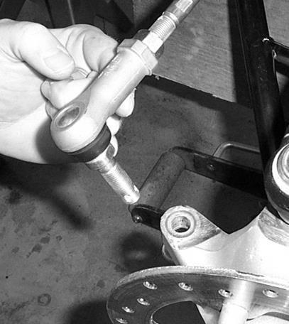
5 5. Disconnect the front shocks from the ATV. 6. Disconnect the factory tie rod from the ATV. 7. Remove the upper and lower control arms. 5


6 8. Remove the hub from the factory axles and pull the axles from the differential. 9. You will need to reuse your factory bushings, sleeves, and ball joints. Make sure that you inspect your bushings and ball joints for wear. Replace them as needed. NOTE: A press or a vise is suggested for removing and replacing the ball joints. Verify that the clip snaps into place after installing the ball joints into the new A-arm 10. Install the 90 grease fittings supplied in the kit into all new arms, front and rear. DO NOT OVER TORQUE FITTINGS! 11. Once you have removed the stock bushings, sleeves, and ball joints from the factory arms install them into the new arms in the kit. If you place some grease on them it makes the installations easier. NOTE: A press is suggested for removing and replacing the ball joints. If you press in the ball joint crooked, DO NOT TRY TO FORCE IT IN! If you try to force it straight you can egg the opening. Press the ball joint out and reinsert it into the opening with a press. Verify that the clip snaps into place after installing the ball joints into the new arm. You should always double check the ball joint snap ring for proper fit. Even if you use snap ring pliers, it may not seat. You can use a flathead screwdriver and a hammer to tap the snap ring to ensure that it is seated into the grove. 12. Remove the factory brake lines. 6


7 13. You need to disconnect the banjo bolt connecting the brake line to the brake lever on the handle bars. Save the hardware to reconnect the new lines. 14. Disconnect the front brake line from the rear master cylinder. You can also remove the rear brake line at this time too. Just don t forget where each one was attached. The rear attaches to the top and the front attaches to the bottom of the master cylinder. 15. There is a junction box located under the handle bars. It is where the lines from the rear master cylinder, left and right front calipers and hand brake meet. You will need to remove the front rack and plastic beneath the handle bars to locate it. If you follow the steering stem down there the wiring harness connects to the fuse box you will find behind the harness the junction box. Disconnect the bolt that holds the junction box in place. Remove the entire brake line assembly. 16. Next you need to identify all the new lines. Locations are determined from the seated position. Here are the measurements: Handle Bar Brake Lever Line 38 (Will have a curved fitting on one end) Front Left Caliper Line 36 Front Right Caliper Line 34 Master Cylinder Line 61 Rear Right Caliper Line The new junction block needs to be located and attached at the frame right behind the fan and fan shroud. Attach it only when you have finished running all the front brake lines. 18. For the brake lever line, run it up through the center of the ATV like the factory line was routed. Connect it to the handle bar brake lever using the factory hardware. 7


8 19. Connect the master cylinder line to the master cylinder using the factory hardware. 20. The master cylinder line will follow along the frame to the front of the ATV. You will use zip ties to connect the line to the frame or wiring harness. (Avoid any moving parts) 8


9 21. For the front caliper lines, run each line from the outside to the inside where the junction block will be located. 22. When all the lines are routed to the junction block location attach them to the junction block. 23. Attach the handle bar and master cylinder lines first and then the caliper lines. 24. The master cylinder line and handle bar brake handle line will be connected to the two holes that are side by side on the front of the block. 25. Left and Right caliper lines will be connected to either side of the block. 26. Once you have the brake lines routed and connected to the junction, connect all front control arms. NOTE: Do not connect to the calipers and brake lines until you have attached the arms and properly routed the brake lines ensuring that they do not come into contact with moving parts. 9


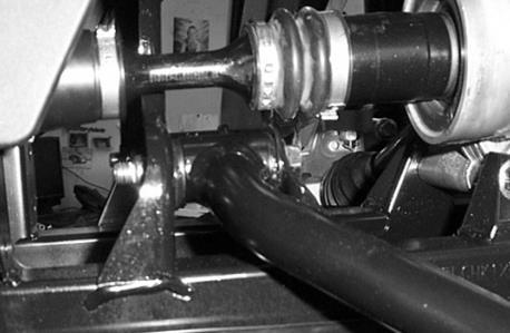
10 27. Use the factory nuts and bolts to connect the new A-arms to the frame. Start with the lower arms first. 28. Next insert the new axles into the differential. 29. Connect the upper control arm using the factory hardware. 30. Insert the axle into the hub assembly and connect the hub to the lower arm. 10


11 31. Connect the hub to the upper arm. Reattach the rotor to the hub assembly. 32. Included in the kit are new axle washers and a new crimp nut. You need to use two washers per axle. Fasten the axle to the hub assembly with the new crimp nut, using a punch to lock the axle nut in place. 33. Insert the long front lift bracket in between the shock mounting tabs, but do not connect at this time. 11


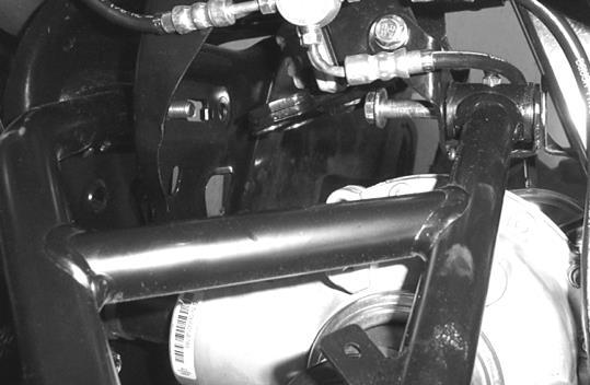
12 34. You will need to relocate the vent tube that is connected the front differential. It will interfere with the bracket and how it mounts. The vent tube is located on the left side of the ATV. 35. Disconnect it from the differential, cut the zip ties holding it in place, and pull it up through the hole near where the shock mounts to the frame. 36. Relocate it to the back side of the frame opposite from where it was running and reconnect it to the differential and secure the line with the zip ties provided. 37. Once you have relocated the vent tube, connect the long bracket to the frame. 38. Using a 10x65mm hex bolt and the front SS spacer connect the bracket to the frame. 39. Place the front JJ small spacer on the outside of the shock mount on the end of the bolt. 12


13 40. Loosely attach the small front lift plate to the front of the frame and secure it with a 10mm lock nut. 41. Insert a 10x65mm hex bolt into the lift bracket, then place the front 31D spacer on the bolt then place the small front lift bracket on the bolt to the outside of the shock mount tabs. Loosely attach a 10mm lock nut 42. Insert a second 10x65mm hex bolt into the lift bracket, then place the front 31D spacer on the bolt then loosely connect it to the small front lift bracket with a 10mm lock nut. 13


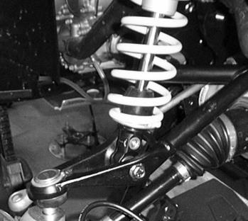
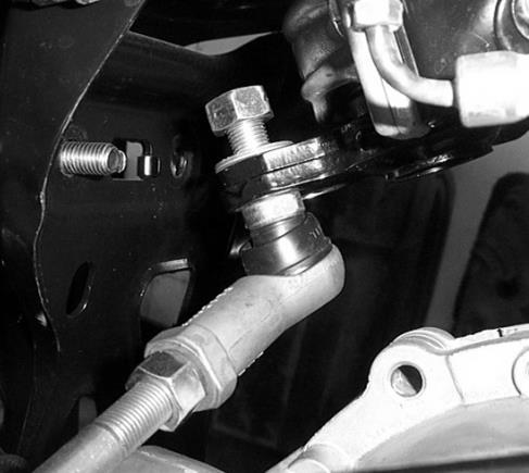
14 43. Insert a third 10x65mm hex bolt into the lift bracket, then place the front 31D spacer on the bolt then loosely connect it to the small front lift bracket with a 10mm lock nut. 44. Now, connect the top of the shock to the brackets using a 10x65 hex bolt, two 10mm washers and10mm lock nut. Place a 10mm washer on either side of the shock eyelet and secure it with the 10mm x 65mm bolt and 10mm lock nut. 45. Connect the bottom of the shock to the new control arm using a 10mm x 65mm bolt and 10mm lock nut. 46. Repeat steps for opposite side and tighten all bolts, and then you can replace the inner fender. 47. Next you will replace the stock tie rods with the new angled rods provided. NOTE: The long end of the rod connects to the steering stem and the short end connects to the knuckle/hub assembly! 14


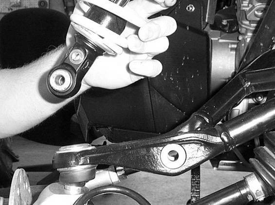
15 48. Place the 12mm right jam on all heim joints at this time. Run the nut all the way down the threads. 49. Connect the heim joints to the tie rods. 50. Connect the short end of the tie rod to the hub assembly with a 12mm x 75mm bolt. Insert onto the 12mm x 75mm bolt a heim alignment cone. 51. Insert the bolt through the heim eye and then place a second heim alignment cone on the bolt. 15


16 52. Connect the tie rod to the hub assembly with a 12mm lock nut. 53. Connect the long end of the tie rod to the steering stem. Place on a 12mm x 75mm bole a heim alignment cone. 54. Insert the bolt through the heim eye and then place a second heim alignment cone on the bolt. 55. Connect the tie rod to the steering stem pushing bolt from the bottom of the stem and fastening it on top with a 12mm lock nut. 56. Connect the calipers to the hub assembly. 57. Route the brake lines to the calipers and connect them using the factory hardware. NOTE: Route the brake lines so that they do not come on to contact with moving parts or get wrapped in the axles! 16


17 58. Use the zip ties provided to secure the lines to the control arms. 59. Make sure to secure the brake line junction block into place once the brake lines have been secured to the control arms. Use zip ties provided in the kit to hole the block in place. 60. You will need to bleed the brakes when you have finished the rear installation. So do not place tires and wheels on at this time. 17


18 Aligning the front wheels 1. Take a tape measure and measure the front and back side of the brake rotors. They must both be the same distance. If they do not then you will need to adjust the rods in or out. This is setting the toe to zero. NOTE: A slight toe out makes the steering less sensitive and the ATV more stable. After setting the toe to zero, you can adjust to your preference. When adjusting the toe, be sure to take the time to adjust both ends half the required distance. 2. The tie rods are designed with a bend in them so that when you turn the handlebars to either full left or right it does not come in contact with the front differential or other components. Make sure when you have finished adjusting the rods and before you secure them tight with the jam nut, that you have verified that the rods do not come in contact with the differential or other parts. Turn the handlebars full left and full right. 3. If the rods come into contact with other parts, spin the rod to achieve clearance and lock it in place with the jam nut. 4. Once you have done these steps, place the tires back on the ATV and torque lugs to factory specifications. Rear Installation 1. Remove the rear trailing arms and shocks. 2. If you have not done so already you need to remove the factory brake line on the rear right trailing arm. 3. Disconnect the brake lines. Save the hardware some of it will be reused! 4. Connect the new brake line to the master cylinder, but not to the caliper! 18


19 5. Next, we recommend that you use two people to disassemble / remove the stock arms and reassemble/install new arms. It takes two people to install the new arms. 6. The following steps must be complete on both sides before you remove the pivot axle that connects both rear trailing arms to the frame 7. Disconnect the caliper/knuckle/hub assembly and brake lines from the factory trailing arms. 8. Next, disconnect the arm from the shock at the shock mount point. Disconnect the shock form the ATV. 9. Disconnect the sway-bar links from the trailing arms. You will reuse the bushings and sleeves in the stock arms. 19


20 10. Now, disconnect the arm from the frame by removing the nut from the left side of the pivot axle on the ATV. Then pull out the pivot axle on the right side of the ATV. It takes two people to do this step! 11. Once you have removed the arm you need to decide if you are going to buy new bearings or try and remove the factory bearings. NOTE: At this point you have two options! You can order replacement bearings and seals. We highly recommend this first option! The bearings in the part of the stock trailing arm that connects to the frame are extremely difficult to remove! The second option is to remove the factory bearings. If you choose this option then you need to be aware that is it extremely difficult to remove these bearings and not damage them! We are not going to include steps on how to remove the factory bearings due to the degree of difficulty in removing them. NOTE: A press or a vise is suggested for removing and replacing the bearings. If you press in the bearing crooked, DO NOT TRY TO FORCE IT IN! If you try to force it straight, you can egg the opening. Press the bearing out and reinsert it into the opening, pressing it in with a vise. When applicable, verify that the retaining clip snaps into place after installing the bearings. You should always double check retaining clips for proper fit. Even if you use snap ring pliers, they may not seat. You can use a flathead screwdriver and a hammer to tap the snap ring to ensure that it is seated into the grove Installation Note: To make the bearings go in easier you can place them in the freezer for several hours. This will shrink the metal enough to help them go in easier. 20


21 12. If you reuse your factory bearing, bushings, seal, sleeves, and retaining clip located in the factory arm. We recommend that you check it for wear. Now insert all into the new High Lifter Trialing Arm. 13. Remove the factory retaining ring that holds the hub bearing in place on the factory arm. Starting with the hub end of the High Lifter Trailing Arm, insert the hub bearing and factory clip. Put a little grease on the outside of the bearing and press it in the trailing arm using a vise. Secure it with retaining ring. 14. Now, install the 4 bearings, 1 sleeve, and 2 seals on the frame end of the trailing arm. This will be difficult!!! Start by installing two of the bearings in one side of the arm. Then insert the sleeve in the opposite end. Next install the remaining bearings. Place the seals and factory spacers on both ends. 21


22 15. Remove the factory bushings and sleeves from the sway bar mount in the stock trailing arm and insert them into the sway bar mount on the High Lifter Trailing Arm. 16. Install the straight grease fitting into the predrilled hole in the sway bar mount. DO NOT OVER TORQUE THE FITTINGS. Make sure to fill with factory approved grease. 17. Before you connect the trailing arm to the ATV you need to install the upper lift brackets and install the spring stiffener on the shock. 18. If you have not done so already, disconnect and remove the rear shock from the ATV. NOTE: If you have an XMR model the spring spacer steps do not apply for your application. This is only for ATV s that are not equipped with FOX or FOX Style adjustable shocks. 22


 back")

23 19. Using a spring compressor, compress the shock and remove the stock spring. 20. Next, insert the spring stiffener onto the shock. 21. Place the stock spring(s) back onto the shock. 22. Now you need to install the upper rear lift brackets. 23


24 23. There are two bolts that secure the fender support brackets to the frame. You need to remove the two bolts. 24. Next you need to insert the rear inner lift bracket. Connect it to the frame using a 10mm x 60mm bolt and 31C spacer between the shock mount tabs. Secure it to the frame loosely with a 10mm lock nut. 25. Connect the outer lift bracket to the inner bracket and to the fender support bracket. There are left and right brackets. Make sure that the holes on the outer lift bracket line up with the hole on the fender support bracket. 24


25 26. Insert into the outer lift bracket two 8mmx 30mm bolts. Place on the back side of the bracket two AA spacers and then connect the bracket to the fender support using the factory bolt holes. 27. Connect the top of the shock to the rear lift brackets with a 10mm x 60mm bolt, two 10mm washers, and 10mm lock nut. Insert the bolt through the bracket, place a 10mm washer on either side of the shock eyelet, and secure it together with the 10mm lock nut. 28. Repeat these for the opposite side at this time. 29. Insert the new axles into the rear differential. 25


26 30. When you have installed the bearings, sleeves, bushings, seal and retaining clip, connect the new trailing arms to the frame using the stock nut and pivot axle that held the factory trailing arm in place. Insert the axle into the trailing arm before you connect it to the frame. 31. Connect the shock to the new trailing arm using a 10mm x 60mm bolt and 10mm nut. 26


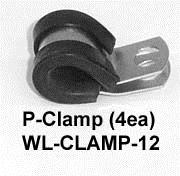
27 32. Connect the rear knuckle assembly and brake calipers to the new trailing arm. 33. Included in the kit are new axle washers and a new crimp nut. You need to use two washers per axle. Fasten the axle to the hub assembly with the new crimp nut, using a punch to lock the axle nut in place. 34. Next attached the factory sway bar link to the new trailing arm using the factory hardware. 35. Attach brake line to the new trailing arm by using the factory hardware, P-clamps, and zip ties provided in the kit. When connecting the P-clamps to the arms use the 6mm x 12mm bolts and 6mm lock nuts provided. 27


28 36. Repeat the steps for the opposite side. 37. Reattach any rack or fenders that were removed at this time. Double check all your brake lines to ensure they are all attached and clear of any moving parts. 38. Once you have all the brake lines in place follow the steps for brake line bleeding. When you have finished bleeding the brakes, attach the wheels torque lugs to factory specification. Brake Line Bleeding Attach the 1 man bleeder bottle, or slip a small hose/tube over the end of the bleed screw and place the other end in a bottle/jar with a little brake fluid in it. That way as air bubbles out it can't return air back up the hose. The only thing being sucked up the hose will be brake fluid. 28
29 Make sure that all brake fluid reservoirs are filled to full level that is indicated on the reservoir container. With the hose in place, open the bleeder screws on all calipers and let the system gravity bleed for about 30 minutes. After the 30 minutes close each bleeder screw then start the second bleeding process. Refill both reservoirs to the full mark. Being careful not to splash brake fluid everywhere, or to let the master cylinder go dry (therefore letting air back into the top of the system) depress the brake lever to force clean brake fluid into the brake line from the master cylinder. Do this 5-6 times for each caliper and refill the master cylinder reservoirs as needed. You will find that you have to refill the master cylinder often as these are long brake lines and small master cylinders. NOTE: Make sure that the cover to the master cylinder is on before you start pumping the brakes!!! When you are confident that all the old fluid and air is purged from the line, close the bleed screw and move on. After all calipers are bled, recap the master cylinders. You should now have good stiff brake levers at the hand and the foot. It will probably take a whole pint sized bottle to do all 4 wheel cylinders. Don't try to save the extra fluid and dispose of used fluid properly. Master Cylinder/Brake Fluid An over-full master cylinder may cause brake drag or brake lock-up, which could result in an accident. Maintain brake fluid at the recommended level. Do not overfill. Never store or use a partial bottle of brake fluid. Brake fluid is hygroscopic, meaning it rapidly absorbs moisture from the air. The moisture causes the boiling temperature of the brake fluid to drop, which can lead to early brake fade and the possibility of brake failure, which could result in an accident. After opening a bottle of brake fluid, always discard any unused portion. Check the brake fluid in the master cylinder before each ride. 1. Position the ATV on a level surface. 2. Position the handlebars so the master cylinder is level. 3. View the brake fluid level through the indicator window on the top of the master cylinder. The eye will appear dark when the fluid level is full. When fluid is low, the eye will be clear. 4. If the fluid level is low, remove the cover screws and add fluid to the fill line. Do not overfill. Use DOT 4 brake fluid only. 5. Reinstall the cover. Torque screws to 7 in-lbs (.8 Nm) 29
30 This product has a dual warranty. The suspension components have a life time warranty and the axles have a limited replacement. Please see information on the following pages. 30

31 High Lifter Lifetime Warranty From the beginning, High Lifter has engineered and manufactured some of the toughest, most durable products on the market. That s why this product comes with a Lifetime Warranty. It s our promise that High Lifter will never let you down. The Lifetime Warranty covers products sold to the original purchaser only and is not transferable. The term of the warranty is for the lifetime of the vehicle in question. Normal wear and tear items and finishes, such as, but not limited to: Heim joints, tie rod ends, ball joints, bearings, seals, bushings, bushing sleeves, zinc plating, powder coating, or chipping and discoloration of any finish is not covered. High Lifter will ship the replacement product after the returned product has been inspected by High Lifter staff. The warranty shall not include claims for damages, installation time or labor charges, economic losses, inconvenience, transportation, towing, down time, direct or indirect or consequential damages or delay resulting from any defect. The warranty does not apply to products that have been improperly applied or improperly installed. Making a warranty claim 1. All claims must be accompanied by the part and the original sales receipt or other acceptable proof of purchase from the original owner. 2. All warranties must be accompanied with a Return Merchandise Authorization (RMA) number. (Contact High Lifter at or for an RMA number) 3. When shipping the damaged product: a. Write the RMA number on the outside of the box. b. Also include the RMA number, proof of purchase and any notes inside the box. c. Please keep your tracking number and shipment information. 4. The customer is responsible for shipping the product to High Lifter--return shipping within the lower 48 states will be paid by High Lifter products. With all warranty claims, only standard shipping services apply. 5. High Lifter will process your order within 24 business hours of receiving the returned item. 6. Ship to: High Lifter Products, 780 Professional Drive North, Shreveport, Louisiana For axle warranty see additional information sheet! 31
32 High Lifter Outlaw DHT XL Big Lift Axle Warranty Program Thank you for purchasing a High Lifter Products Big Lift equipped with a set of Outlaw DHT XL Big Lift Axles. Our axles have been engineered to provide superior performance for use on your ATV/UTV. LIMITED WARRANTY: HIGH LIFTER PRODUCTS, INC. warrants to the ORIGINAL purchaser of any High Lifter Big Lift equipped with 4-Outlaw DHT XL Big Lift Axles for a total of one (1) axle warranty claim or breakage per set of 4 axles for a period of one (1) year from the original date of purchase. This warranty covers defects in material, workmanship or failure in normal service. This warranty is not for each individual axle, but for the set of (4). Your 1-year warranty period starts from the date of original purchase. You are allowed 1 approved axle warranty claim or breakage during your 1-year warranty period. If there is additional DHT XL Big Lift axle breakage, you may follow our DHT XL Big Lift axle warranty claim process. This allows you to purchase a replacement High Lifter DHT XL Big Lift axle at a reduced price of $75.00 per axle plus all applicable shipping charges. After your 1-year warranty expires, a replacement axle can be purchased at High Lifter s full standard published pricing. The limited warranty is subject to the following conditions: a) The product is properly installed. b) If a lift kit requires or suggests the need for extended-length axles, those axles must meet requirements. c) HIGH LIFTER is not liable for any incidental or consequential damages to anything other than the axle covered by this warranty, including labor costs to remove/reinstall, loss of use of machine, loss of time, damage to housings, or damage to any OEM supplied parts. d) If the axle has been disassembled or modified by a third party, or has OEM parts installed on the axle, the warranty is null and void. e) Any axle damaged in a collision is excluded from this warranty. f) Warranty is non-transferable from the ORIGINAL purchaser. g) HIGH LIFTER reserves the right to inspect the axle and determine any defects in installation to determine the validity of a warranty s claim. This may include the ORIGINAL purchaser providing photographs of the ATV/UTV and its installed lift kit. h) Boots damaged by CV joint failures are covered under this warranty. Boots damaged by punctures or tears from trail obstructions are not covered under this warranty. Boot inspection should be a part of regular ATV/UTV maintenance. i) This warranty does not apply to and will not cover any products installed on vehicles used for any type of commercial use, rental use, lease use or ATV/UTV Racing. REFUSED SHIPMENTS/ORDER CANCELLATION: Refused shipments are subject to a 25% restocking fee plus return freight. If a customer wishes to cancel an order (provided it is not a special order product), it is the responsibility of the customer to cancel the order prior to the product being shipped. If a customer cancels an order after product has been shipped, the refused shipment, cancellation, or return will be subject to a 25% restocking fee and any freight charges incurred. For orders outside the United States, any fees associated with customs or duties are non refundable. 32
33 DAMAGED SHIPMENTS: All claims for damaged shipments must be made within 72 hours of delivery to the point of destination. Any damage to package should be noted with carrier at the time of delivery if possible. We will not be responsible for damage claims made over 72 hours after delivery to the point of destination. OBTAINING A WARRANTY CLAIM: All returns for warranty must be pre-approved by calling After warranty approval has been granted and a Return Merchandise Authorization (RMA) number issued, the axle must be received by HIGH LIFTER PRODUCTS within 15 calendar days. The RMA number must be clearly displayed on the return box or the return will be refused. An RMA number does not imply warranty service, warranty replacement or a refund will be issued or provided on any product, but only that we will inspect the axle for warranty claims. For orders outside the United States, any fees associated with customs or duties are non-refundable. All DHT XL Big Lift axles being considered for warranty repair or replacement must be returned to High Lifter for inspection and approval before a warranty claim can be processed. No replacement product will be sent before an axle with a pending warranty claim has properly went through our warranty claims process and has been received, inspected and approved for warranty by High Lifter. All claims must be accompanied by a copy of the original sales receipt or invoice detailing date and place of purchase, as well as a written explanation of the problem, a valid phone contact number, and address. A copy of this original sales receipt or invoice must be included with EVERY axle being returned for warranty repair or replacement consideration. The purchaser is responsible for all freight charges, taxes, duties or fees on a warranty claim, including incoming freight to High Lifter and return freight to the purchaser. 33
34 High Lifter Products Outlaw DHT XL Big Lift Axle Warranty Claim Name: Address: Phone Number: Address: Axle Product Number: Place of Purchase: Date of Purchase: Reason for Return: Reminder This claim must be accompanied by a copy of the original receipt. 34
It is your responsibility to always inform other operators and passengers of this vehicle and about the added risks.
 780 Professional Drive N. Shreveport, LA 71105 Phone (318)-524-2270 Fax (318)-524-2297 www.highlifter.com Read before Installation This product is designed for use on RUVs for extreme mud riding conditions.
It is your responsibility to always inform other operators and passengers of this vehicle and about the added risks.
 780 Professional Drive N. Shreveport, LA 71105 Phone (318)-524-2270 Fax (318)-524-2297 www.highlifter.com Read before Installation This product is designed for use on ATVs and/or RUVs for extreme mud riding
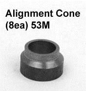
2. Remove front wheels.
 1 PARTS DIAGRAM 2 Installation Instructions: (PASSENGER SIDE) 1. Place jack under center of RUV front end and lift until front wheels clear the ground. Be careful to support the RUV properly so that it
4. Remove the cotter pin that secures the castle nut to the axle. Once you have done this remove the castle nut and pull off the hub/rotor assembly.
 780 Professional Drive N. Shreveport, LA 71105 Phone (318)-524-2270 Fax (318)-524-2297 Max Clearance Honda Pioneer 1000 Front Forward Arched Control Arm Kit Read before Installation This product is designed
It is your responsibility to always inform other operators and passengers of this vehicle and about the added risks.
 780 Professional Drive N. Shreveport, LA 71105 Phone (318)-524-2270 Fax (318)-524-2297 www.highlifter.com Read before Installation This product is designed for use on RUVs for extreme mud riding conditions.
Max Clearance Polaris RZR 900 S 60 Rear Lower Arched Control Arm Kit
 780 Professional Drive N. Shreveport, LA 71105 Phone (318)-524-2270 Fax (318)-524-2297 Max Clearance Polaris RZR 900 S 60 Rear Lower Arched Control Arm Kit Read before Installation This product is designed
Max Clearance Polaris Sportsman Arched A-arm Kit
 780 Professional Drive N. Shreveport, LA 71105 Phone (318)-524-2270 Fax (318)-524-2297 Max Clearance Polaris Sportsman Arched A-arm Kit Read before Installation This product is designed for use on ATVs
INSTALLATION INSTRUCTIONS *When referring to left and right positions during the installation process, it is from the seated position*
 1 PARTS DIAGRAMS 2 3 4 INSTALLATION INSTRUCTIONS *When referring to left and right positions during the installation process, it is from the seated position* FRONT LIFT INSTALLATION 1. Place a jack under
Max Clearance Honda Front Lower Arched Control Arm Kit
 780 Professional Drive N. Shreveport, LA 71105 Phone (318)-524-2270 Fax (318)-524-2297 Max Clearance Honda Front Lower Arched Control Arm Kit Read before Installation This product is designed for use on
780 Professional Drive N. Shreveport, LA Phone (318) Fax (318)
 Fax (318)") 780 Professional Drive N. Shreveport, LA 71105 Phone (318)-524-2270 Fax (318)-524-2297 www.highlifter.com Polaris RZR 570 Lift Kit Installation Instructions Read before Installation This product is designed
780 Professional Drive N. Shreveport, LA 71105 Phone (318)-524-2270 Fax (318)-524-2297 www.highlifter.com Polaris RZR 570 Lift Kit Installation Instructions Read before Installation This product is designed
780 Professional Drive N. Shreveport, LA Phone (318) Fax (318) Suzuki King Quad 750/500Lift Kit Installation Instructions
 Fax (318) Suzuki King Quad 750/500Lift Kit Installation Instructions") 780 Professional Drive N. Shreveport, LA 71105 Phone (318)-524-2270 Fax (318)-524-2297 Suzuki King Quad 750/500Lift Kit Installation Instructions Read before Installation This product is designed for use
780 Professional Drive N. Shreveport, LA 71105 Phone (318)-524-2270 Fax (318)-524-2297 Suzuki King Quad 750/500Lift Kit Installation Instructions Read before Installation This product is designed for use
780 Professional Drive N Shreveport, LA Phone (318) Polaris Ranger RZR 1000 XP Upper Radius Bars
 Polaris Ranger RZR 1000 XP Upper Radius Bars") 780 Professional Drive N Shreveport, LA 71105 Phone (318)524-2270 Polaris Ranger RZR 1000 XP Upper Radius Bars Read before Installation This product is designed for use on ATVs and/or RUVs to increase
780 Professional Drive N Shreveport, LA 71105 Phone (318)524-2270 Polaris Ranger RZR 1000 XP Upper Radius Bars Read before Installation This product is designed for use on ATVs and/or RUVs to increase
FRONT LIFT INSTALLATION *When referring to left and right positions during the installation process, it is from the seated position*
 1 Parts Diagram 2 FRONT LIFT INSTALLATION *When referring to left and right positions during the installation process, it is from the seated position* 1. Place UTV transmission in park. Place jack under
780 Professional Drive N. Shreveport, LA Phone (318) Fax (318) Lift Kit Installation Instructions
 Fax (318) Lift Kit Installation Instructions") 780 Professional Drive N. Shreveport, LA 71105 Phone (318)-524-2270 Fax (318)-524-2297 Yamaha Grizzly 700 Lift Kit Lift Kit Installation Instructions Read before Installation This product is designed for
780 Professional Drive N. Shreveport, LA 71105 Phone (318)-524-2270 Fax (318)-524-2297 Yamaha Grizzly 700 Lift Kit Lift Kit Installation Instructions Read before Installation This product is designed for
Polaris Ranger RZR 1000 XP Radius Bars PSRA-RZR1
 780 Professional Drive N Shreveport, LA 71105 Phone (318)524-2270 Polaris Ranger RZR 1000 XP Radius Bars PSRA-RZR1 Read before Installation This product is designed for use on ATVs and/or RUVs to increase
780 Professional Drive N. Shreveport, LA Phone (318) Fax (318) Honda Lift Kit Installation Instructions
 Fax (318) Honda Lift Kit Installation Instructions") 780 Professional Drive N. Shreveport, LA 71105 Phone (318)-524-2270 Fax (318)-524-2297 www.highlifter.com Honda Lift Kit Installation Instructions Read before Installation This product is designed for
780 Professional Drive N. Shreveport, LA 71105 Phone (318)-524-2270 Fax (318)-524-2297 www.highlifter.com Honda Lift Kit Installation Instructions Read before Installation This product is designed for
780 Professional Drive N. Shreveport, LA Phone (318) Fax (318) Honda 420 Installation Instructions
 Fax (318) Honda 420 Installation Instructions") 780 Professional Drive N. Shreveport, LA 71105 Phone (318)-524-2270 Fax (318)-524-2297 www.highlifter.com Honda 420 Installation Instructions Read before Installation This product is designed for use on
780 Professional Drive N. Shreveport, LA 71105 Phone (318)-524-2270 Fax (318)-524-2297 www.highlifter.com Honda 420 Installation Instructions Read before Installation This product is designed for use on
NOTE: IF RUNNING FACTORY RANGER 900 ALUMINUM WHEELS OR AFTERMARKET ALUMINUM WHEELS THEN SPACERS ARE NOT REQUIRED.
 780 Professional Dr. North, Shreveport, LA. 318-524-2270 Polaris 900 XP Ranger Lift Kit Installation Instructions Read before Installation This product is designed for use on ATVs and/or RUVs to increase
780 Professional Dr. North, Shreveport, LA Polaris Ranger Lift Kit Installation Instructions CLKCMX3-02
 780 Professional Dr. North, Shreveport, LA. 318-524-2270 Polaris Ranger Lift Kit Installation Instructions CLKCMX3-02 Read before Installation This product is designed for use on ATVs and/or RUVs to increase
780 Professional Drive N. Shreveport, LA Phone (318) Fax (318) Kawasaki Teryx 4-Seater
 Fax (318) Kawasaki Teryx 4-Seater") 780 Professional Drive N. Shreveport, LA 71105 Phone (318)-524-2270 Fax (318)-524-2297 Kawasaki Teryx 4-Seater Read before Installation This product is designed for use on ATVs and/or RUVs to increase
780 Professional Drive N. Shreveport, LA 71105 Phone (318)-524-2270 Fax (318)-524-2297 Kawasaki Teryx 4-Seater Read before Installation This product is designed for use on ATVs and/or RUVs to increase
780 Professional Drive N. Shreveport, LA Phone (318) Fax (318) Lift Kit Installation Instructions
 Fax (318) Lift Kit Installation Instructions") 780 Professional Drive N. Shreveport, LA 71105 Phone (318)-524-2270 Fax (318)-524-2297 www.highlifter.com Polaris Mid-Size 570 RANGER Models Lift Kit Installation Instructions Read before Installation
780 Professional Drive N. Shreveport, LA 71105 Phone (318)-524-2270 Fax (318)-524-2297 www.highlifter.com Polaris Mid-Size 570 RANGER Models Lift Kit Installation Instructions Read before Installation
780 Professional Drive N. Shreveport, LA Phone (318) Fax (318)
 Fax (318)") 780 Professional Drive N. Shreveport, LA 71105 Phone (318)-524-2270 Fax (318)-524-2297 www.highlifter.com KLKM610-00 Read before Installation This product is designed for use on ATVs and/or RUVs to increase
780 Professional Drive N. Shreveport, LA 71105 Phone (318)-524-2270 Fax (318)-524-2297 www.highlifter.com KLKM610-00 Read before Installation This product is designed for use on ATVs and/or RUVs to increase
Honda 700 Pioneer Lift Kit
 780 Professional Drive N. Shreveport, LA 71105 Phone (318)-524-2270 Fax (318)-524-2297 www.highlifter.com Honda 700 Pioneer Lift Kit Read before Installation This product is designed for use on ATVs and/or
(318) (318) & 800 RANGER IRS
 (318) & 800 RANGER IRS") 780 Professional Drive N. Shreveport, LA 71105 Phone (318)-524-2270 Fax (318)-524-2297 Polaris 700 & 800 RANGER IRS Models Lift Kit Installation Instructions Read before Installation This product is designed
780 Professional Drive N. Shreveport, LA 71105 Phone (318)-524-2270 Fax (318)-524-2297 Polaris 700 & 800 RANGER IRS Models Lift Kit Installation Instructions Read before Installation This product is designed
780 Professional Drive N. Shreveport, LA Phone (318) Fax (318) Polaris RZR TURBO XP
 Fax (318) Polaris RZR TURBO XP") 780 Professional Drive N. Shreveport, LA 71105 Phone (318)-524-2270 Fax (318)-524-2297 www.highlifter.com Polaris RZR TURBO XP Read before Installation This product is designed for use on ATVs and/or RUVs
780 Professional Drive N. Shreveport, LA 71105 Phone (318)-524-2270 Fax (318)-524-2297 www.highlifter.com Polaris RZR TURBO XP Read before Installation This product is designed for use on ATVs and/or RUVs
NOTE: IF RUNNING FACTORY RANGER ALUMINUM WHEELS OR AFTERMARKET ALUMINUM WHEELS THEN SPACERS ARE NOT REQUIRED.
 780 Professional Dr. North, Shreveport, LA. 318-524-2270 Polaris Ranger Lift Kit Installation Instructions PLK1000R-51 Read before Installation This product is designed for use on ATVs and/or RUVs to increase
780 Professional Drive N. Shreveport, LA Phone (318) Fax (318)
 Fax (318)") 780 Professional Drive N. Shreveport, LA 71105 Phone (318)-524-2270 Fax (318)-524-2297 Yamaha YXZ 1000 Lift Kit Installation Instructions Read before Installation This product is designed for use on ATVs
780 Professional Drive N. Shreveport, LA 71105 Phone (318)-524-2270 Fax (318)-524-2297 Yamaha YXZ 1000 Lift Kit Installation Instructions Read before Installation This product is designed for use on ATVs
780 Professional Drive N. Shreveport, LA Phone (318) Fax (318) Kawasaki Mule Pro FXT
 Fax (318) Kawasaki Mule Pro FXT") 780 Professional Drive N. Shreveport, LA 71105 Phone (318)-524-2270 Fax (318)-524-2297 www.highlifter.com Kawasaki Mule Pro FXT Read before Installation This product is designed for use on ATVs and/or
780 Professional Drive N. Shreveport, LA 71105 Phone (318)-524-2270 Fax (318)-524-2297 www.highlifter.com Kawasaki Mule Pro FXT Read before Installation This product is designed for use on ATVs and/or
780 Professional Drive N. Shreveport, LA Phone (318) Fax (318) KLKM
 Fax (318) KLKM") 780 Professional Drive N. Shreveport, LA 71105 Phone (318)-524-2270 Fax (318)-524-2297 www.highlifter.com KLKM3000-00 Read before Installation This product is designed for use on ATVs and/or RUVs to increase
780 Professional Drive N. Shreveport, LA 71105 Phone (318)-524-2270 Fax (318)-524-2297 www.highlifter.com KLKM3000-00 Read before Installation This product is designed for use on ATVs and/or RUVs to increase
SPORTSMAN 800/500 INSTALLATION NOTES FOR 2011 MODELS:
 780 Professional Drive N Shreveport, LA 71105 Phone: 318-524-2270 Polaris Sportsman Lift Kit Read before Installation This product is designed for use on ATVs and/or RUVs to increase ground clearance and
Max Clearance Arctic Cat Forward Front Upper & Lower Arched Control Arm Kit
 780 Professional Drive N. Shreveport, LA 71105 Phone (318)-524-2270 Fax (318)-524-2297 Max Clearance Arctic Cat Forward Front Upper & Lower Arched Control Arm Kit The Max Clearance Control Arm Kit is designed
Suzuki 500 (98+) Lift Kit Installation Instructions
 Lift Kit Installation Instructions") 780 Professional Drive N. Shreveport, LA 71105 Phone (318)-524-2270 Fax (318)-524-2297 www.highlifter.com Suzuki 500 (98+) Lift Kit Installation Instructions Read before Installation This product is designed
780 Professional Drive N. Shreveport, LA 71105 Phone (318)-524-2270 Fax (318)-524-2297 www.highlifter.com Suzuki 500 (98+) Lift Kit Installation Instructions Read before Installation This product is designed
Polaris RZR 900 XP Arched Trailing Arms PSATA-RZR9
 780 Professional Drive N Shreveport, LA 71105 Phone (318)524-2270 Polaris RZR 900 XP Arched Trailing Arms PSATA-RZR9 Read Before Installation This product is designed for use on ATVs and/or RUVs to increase
This lift allows you to convert from lifted to unlifted positions!
 780 Professional Drive N. Shreveport, LA 71105 Phone (318)-524-2270 Fax (318)-524-2297 Polaris Ranger RZR 900 XP This lift allows you to convert from lifted to unlifted positions! Read Before Installation
High Lifter Products, Inc.
 High Lifter Products, Inc. Phone 318-524-2270 780 N Professional Dr Fax 318-524-2297 Shreveport, LA 71105 www.highlifter.com Proseries Polaris Forward A-arm Kit The Proseries A-arm kit is designed to permit
Arctic Cat Wild Cat Upper Radius Bars
 780 Professional Drive N Shreveport, LA 71105 Phone (318)524-2270 Arctic Cat Wild Cat Upper Radius Bars Read Before Installation This product is designed for use on ATVs and/or RUVs to increase ground
Max Clearance Polaris Ranger 900 XP Front Forward Arched Control Arm Kit
 780 Professional Drive N. Shreveport, LA 71105 Phone (318)-524-2270 Fax (318)-524-2297 Max Clearance Polaris Ranger 900 XP Front Forward Arched Control Arm Kit The Max Clearance Control Arm Kit is designed
Suzuki 700 Lift Kit Lift Kit Installation Instructions
 High Lifter Products, Inc. 318-524-2270 780 N Professional Drive 318-524-2297 Shreveport, LA 71105 Suzuki 700 Lift Kit Lift Kit Installation Instructions Read Before Installation This product is designed
PARTS DIAGRAM INSTALLATION INSTRUCTIONS
 SBLK-RZR1-R 1 PARTS DIAGRAM INSTALLATION INSTRUCTIONS (LH) - LEFT HAND (RH) - RIGHT HAND 1. First, you need to preassemble the new heavy duty High Lifter sway bar link. 2. If not already done, fasten the
" CHEVY / GMC WD BASIC KIT
 84302 2007-2013 6" CHEVY / GMC 1500 4WD BASIC KIT 100% Bolt On 6 Spindle Kit Front Differential Is Dropped A Full 6 To Maintain Proper CV Axle Angles Impact Struts To Distribute Front Suspension Impact
6 Lift Kit - Kawasaki Teryx4
 2753 Michigan Road Madison, Indiana 47250 855-743-3427 INSTALLATION INSTRUCTIONS 6 Lift Kit - Kawasaki Teryx4 1 Spacers are required if running stock Wheels Driver C A D B Passenger Item Description A
3 Lift Kit: for Polaris General
 INSTALLATION INSTRUCTIONS 2753 Michigan Road Madison, Indiana 47250 855-743-3427 3 Lift Kit: for Polaris General Item Description Qty A Rear Shock Bracket Brace 1 B Front Shock Bracket 1 C Rear Shock Bracket
3 Lift Kit: for Polaris General
 INSTALLATION INSTRUTIONS 740B lifty Drive Madison, Indiana 47250 812-574-7777 3 Lift Kit: for Polaris General Item Description Qty A Rear Shock Bracket Brace 1 B Shock Bracket 1 Rear Shock Bracket 2 D
SPECIAL TOOLS REQUIRED:
 INSTALLATION INSTRUCTIONS FOR 2010-15 TOYOTA 4RUNNER WITH XREAS SUSPENSION 3 SUSPENSION LIFT KIT PART NUMBER 432X WARNING!!! READ AND UNDERSTAND ALL INSTRUCTIONS BEFORE PROCEEDING. MAKE SURE THAT YOU HAVE
INSTALLATION INSTRUCTIONS FOR FORD 4WD SUPER DUTY F /2 COIL SPRING SUSPENSION SYSTEM
 INSTALLATION INSTRUCTIONS FOR 2005-07 FORD 4WD SUPER DUTY F250-350 4 1/2 COIL SPRING SUSPENSION SYSTEM Requires the following parts (sold separately) for a complete installation: KIT PART NUMBER (6345
INSTALLATION INSTRUCTIONS FOR FORD 4WD SUPER DUTY F COIL SPRING SUSPENSION SYSTEM
 INSTALLATION INSTRUCTIONS FOR 2008-10 FORD 4WD SUPER DUTY F250-350 6 COIL SPRING SUSPENSION SYSTEM Requires the following parts (sold separately) for a complete installation: KIT PART NUMBER (6860) REQUIRES
INSTALLATION INSTRUCTIONS FOR FORD 4WD SUPER DUTY 6 SUSPENSION SYSTEM
 INSTALLATION INSTRUCTIONS FOR 1999-2004 FORD 4WD SUPER DUTY 6 SUSPENSION SYSTEM Requires the following parts for a complete installation: Front Leaf Springs P/N 60SD6 Hardware Kit P/N 6000H Vehicle specific
Installation manual 3 suspension system Toyota Tacoma 4 x 4 & PreRunner Part # sj rev.03
 Part #: 52904 1995-2004 Toyota Tacoma 4 x 4 & PreRunner 3 suspension system Parts list: Part # Description Qty. 52904-01 Rear brake proportioning valve bracket 1 52907-02 Front pre load spacer 2 52904-03
INSTALLATION INSTRUCTION Rev A
 INSTALLATION INSTRUCTION 88587 Rev A FOR RANCHO SUSPENSION SYSTEM RS6587B: 2009 DODGE RAM 1500 READ ALL INSTRUCTIONS THOROUGHLY FROM START TO FINISH BEFORE BEGINNING INSTALLATION IMPORTANT NOTES! WARNING:
INSTALLATION INSTRUCTION 88581
 INSTALLATION INSTRUCTION 88581 FOR RANCHO SUSPENSION SYSTEM RS6581B: DODGE RAM READ ALL INSTRUCTIONS THOROUGHLY FROM START TO FINISH BEFORE BEGINNING INSTALLATION Rev C IMPORTANT NOTES! WARNING: This suspension
INSTALLATION MANUAL 4 I.F.S. SUSPENSION CURR. CHEVY SUBURBAN / YUKON XL (WITH 5 LINK REAR END) PART # 14965
 PART # 14965") PART NUMBER : 14965 2000 CURR. SUBURBAN W/ REAR COIL SPRINGS 4 SUSPENSION SYSTEM WITH FRONT SPINDLES PARTS LIST: Part # Description Qty. C4I1SN-07 Passenger Side Differential Drop 1 C4I1SN-23 Driver Side
PART NUMBER : 14965 2000 CURR. SUBURBAN W/ REAR COIL SPRINGS 4 SUSPENSION SYSTEM WITH FRONT SPINDLES PARTS LIST: Part # Description Qty. C4I1SN-07 Passenger Side Differential Drop 1 C4I1SN-23 Driver Side
Installation manual. Toyota Tundra 4WD & 2WD. 2.5 Suspension kit. Part # Part # Important customer information:
 Installation manual 2007-2016 Toyota Tundra 4WD & 2WD 2.5 Suspension kit Part # 53070 sj11082011rev.03 Part # 53070 2007-2016 Toyota Tundra 4WD & 2WD 2.5 Suspension kit Part # Description Qty. 53070-01
INSTALLATION MANUAL TOYOTA TUNDRA 5 SUSPENSION SYSTEM PART # 55905
 PART NUMBER : 55905 1999 2003 TOYOTA TUNDRA 5 SUSPENSION SYSTEM PARTS LIST: Part # Description Qty. 55900-01 Driver Side Spindle 1 55900-02 Passenger Side Spindle 1 55905-03 Rear brake proportioning valve
Gen 2 Portal Gear Hubs for Polaris Ranger Crew 570/900
 2753 Michigan Road Madison, Indiana 47250 855-743-3427 INSTALLATION INSTRUCTIONS Gen 2 Portal Gear Hubs for Polaris Ranger Crew 570/900 A Item Description Qty A Rotor 4 B Gear Box, L 2 C Gear Box, R 2
Verify, and adjust if necessary, centering of Rack and Pinion before installing.
 Verify, and adjust if necessary, centering of before installing. measurement 1: face of Tie Rod End inside of 1. Measure distance from inside of Rack and Pinion to face of Tie Rod End. 2. Measure distance
UPPER TRAILING ARM REMOVAL
 #1204 MUSTANG UPPER TRAILING ARMS Thank you for your purchase. Please call us at (562) 907-7757 if you have any questions regarding your Hotchkis Performance products. Visit us online @ www.hotchkis.net
RHINO SUSPENSION SYSTEM INSTALLATION INSTRUCTIONS
 PARTS INCLUDED: 2 FRONT UPPER A-ARMS 2 FRONT LOWER A-ARMS 2 UNI-BALL JOINTS 2 UNI-BALL JOINT STUDS 2 UNI-BALL JOINT CAPS 2 RETAINING RINGS 1 FRONT SHOCK ASSEM. 2 DELRON STEERING STOPS 2 SHOCK MOUNT SPACERS
FRONT DRIVELINE MODIFICATION MAY BE NECESSARY!!!!
 INSTALLATION INSTRUCTIONS FOR 2009 DODGE 2500/3500 4WD & 1500 Mega Cab 6 SUSPENSION SYSTEM PART NUMBER 7206 Requires the following parts (sold separately) for a complete installation: Front Coil Spring
INSTALLATION INSTRUCTIONS
 INSTALLATION INSTRUCTIONS 2005-2012 Nissan Xterra/Frontier / Pathfinder PART NUMBERS: NP17500, NP17525, NP17550 FRONTIER PARTS & CORRESPONDING HARDWARE LIST XTERRA PATHFINDER ABOVE LISTED 1/2 Metal Lock
CHEVY / GMC 1500HD / 2500HD 2WD 8 LUG 7 BASIC KIT
 85101 2000-2010 CHEVY / GMC 1500HD / 2500HD 2WD 8 LUG 7 BASIC KIT C8510-4 MAIN BOX KIT W/ HARDWARE 1) FRONT X MEMBER 1) REAR X MEMBER 2) TORSION BAR DROPS 1) LEFT BUMP STOP 1) RIGHT BUMP STOP 2) SWAY BAR
FORD F-250/350 SUPER DUTY 4WD FTS22142 FRONT DUAL SHOCK SYSTEM
 2011-2015 FORD F-250/350 SUPER DUTY 4WD FTS22142 FRONT DUAL SHOCK SYSTEM FTS22142 2011 F250/350 MULTI SHK KIT FT30446 Hardware Kit 1 FT30167BK UPPER HOOP DRVR 05 FORD SD 10 1/2-13 X 3 HEX CAP SCREW ZINC
INSTALLATION MANUAL TOYOTA TACOMA 5 SUSPENSION SYSTEM PART # 54900
 PART NUMBER : 54900 1996 2004 TOYOTA TACOMA 5 SUSPENSION SYSTEM PARTS LIST: Part # Description Qty. 55900-01 Driver Side Spindle 1 55900-02 Passenger Side Spindle 1 54900-01 Rear brake proportioning valve
Installation Manual Ram x4 4 Lift w/upper control arms. Part # Part # 34105
 Installation Manual 2009 2018 Ram 1500 4x4 4 Lift w/upper control arms Part # 34105 ss09172014 Part # 34105 2009-2018 Ram 1500 4x4 4 suspension system w/upper control arms Part # Description Qty. 34105-01
(800) MON-FRI 7AM-5PM PST OR WEBSITE: ReadyLIFT.COM **Please retain this document in your vehicle at all times**
 MON-FRI 7AM-5PM PST OR WEBSITE: ReadyLIFT.COM **Please retain this document in your vehicle at all times**") IF your ReadyLIFT product has a damaged or missing part, please contact customer service directly. For warranty issues please return to the place of installation and contact ReadyLIFT. A NEW REPLACEMENT
IF your ReadyLIFT product has a damaged or missing part, please contact customer service directly. For warranty issues please return to the place of installation and contact ReadyLIFT. A NEW REPLACEMENT
INSTALLATION MANUAL 4.5 I.F.S. SUSPENSION CURR. FORD F150 W/4.2 OR 4.6 LITER PART # 24940
 INSTALLATION MANUAL 4.5 I.F.S. SUSPENSION 1997- CURR. FORD F150 W/4.2 OR 4.6 LITER PART # 24940 SJ101402 PART NUMBER : 24940 1997 CURR. FORD F150 W/4.2 OR 4.6 LITER 4.5 SUSPENSION SYSTEM WITH FRONT SPINDLES
Verify, and adjust if necessary, centering of Rack and Pinion before installing.
 Verify, and adjust if necessary, centering of Rack and Pinion before installing. 1. Measure distance from inside of Rack and Pinion to face of Tie Rod End. 2. Measure distance from face of Tie Rod End
5) The trailing arm should then pivot smoothly on the chassis. 6) Install the rear bolt. 7) Place one drop of blue Loctite
 The trailing arm should then pivot smoothly on the chassis. 6) Install the rear bolt. 7) Place one drop of blue Loctite") INSTALLATION INSTRUCTIONS 1301 / 1302 / 1305 / 1306 THANK YOU FOR CHOOSING HOTCHKIS PERFORMANCE PRODUCTS Removal of Stock Lower Trailing Arms 1) Place car on level surface. 2) Support rear of the car on
INSTALLATION INSTRUCTIONS 1301 / 1302 / 1305 / 1306 THANK YOU FOR CHOOSING HOTCHKIS PERFORMANCE PRODUCTS Removal of Stock Lower Trailing Arms 1) Place car on level surface. 2) Support rear of the car on
'64-72 Chevelle/ A Body Rear Coilover Conversion Kit
 Nov 3, 2017 '64-72 Chevelle/ A Body Rear Coilover Conversion Kit Includes instructions for Currie Brand Axles The following instructions are intended for professional installers and are guidelines only.
Installation manual 6 Suspension system Chevy or GMC 1500 Heavy Duty Part # 16958
 Part # 16958 2001 2005 Chevy or GMC 1500 Heavy Duty 6 Suspension system Parts contained in Box 1 of 3 Part # Description Qty. 16985-04 One piece lower sub frame 1 16985-12 Lateral compression arms 2 16985NB
WARNING!!! READ AND UNDERSTAND ALL INSTRUCTIONS BEFORE PROCEEDING. MAKE SURE THAT YOU HAVE ALL TOOLS AND PARTS BEFORE BEGINNING THE INSTALLATION.
 INSTALLATION INSTRUCTIONS FOR 2005-2015 TOYOTA TACOMA 4 X 4 AND PRERUNNER, 2003-2015 4RUNNER, 2007-2014 FJ CRUISER 1.5" FRONT LEVELING KIT PART NUMBER 415 WARNING!!! READ AND UNDERSTAND ALL INSTRUCTIONS
2236 Sway Bar Installation Instructions
 2236 Sway Bar Installation Instructions Thank you for your purchase of this Hotchkis Performance product. Your stabilizer bar set was designed with the performance and durability you ve come to expect
Rhino Long Travel Spindle Kit Yamaha Rhino FTR10072
 4331 EUCALYPTUS AVE. ~~ CHINO, CA 91710 909-597-7800 Fax 909-597-7185 Rhino Long Travel Spindle Kit 2005-08 Yamaha Rhino FTR10072 PARTS LIST: QTY. Part # Description 1 FTS95061D Rhino Spindle Driver 1
PARTS LIST INCLUDED IN KIT TORQUE SPECIFICATIONS PRODUCT SAFETY LABEL MUST BE INSTALLED INSIDE CAB IN PLAIN VIEW OF ALL OCCUPANTS.
 INSTALLATION INSTRUCTIONS FOR 2010-15 TOYOTA 4RUNNER SR5 AND SPORT (Non-Air Leveling & Non-X-REAS) AND FOR 2010-14 TOYOTA FJ CRUISER 2WD & 4WD 3 SUSPENSION LIFT KIT PART NUMBER 432 WARNING!!! READ AND
DODGE DIESEL KIT DODGE DIESEL KIT
 69120 2009-2013 DODGE 2500 8 DIESEL KIT 2009-2012 DODGE 3500 8 DIESEL KIT Heavy Duty Long Arm Construction For Superior Ride Quality And Travel Lower Arms Constructed Of 1.75 DOM Tubing W/ Urethane Bushing
INSTALLATION MANUAL 4 I.F.S. SUSPENSION SYSTEM CHEVY / GMC LUG PART # 14810
 INSTALLATION MANUAL 4 I.F.S. SUSPENSION SYSTEM 1988-1998 CHEVY / GMC 1500 6 LUG PART # 14810 Sj051904rev.03 PART NUMBER : 14810 1988-1998 CHEVY / GMC 1500 6 LUG 4 SUSPENSION SYSTEM WITH FRONT SPINDLES
Installation Instructions FRONT SUSPENSION INSTRUCTIONS: 1) Disconnect the negative terminal on the battery.
 Disconnect the negative terminal on the battery.") 75004 75001-5 COPONENT BOX 1 1) Rear Cross Member 1) Front Cross Member 1) Left Strut Spacer 1) Right Strut Spacer 2) Sway Bar Drops 1) Left Compression Strut 1) Right Compression Strut 2) Tie rods T538
75004 75001-5 COPONENT BOX 1 1) Rear Cross Member 1) Front Cross Member 1) Left Strut Spacer 1) Right Strut Spacer 2) Sway Bar Drops 1) Left Compression Strut 1) Right Compression Strut 2) Tie rods T538
INSTALLATION MANUAL 4 I.F.S. SUSPENSION SYSTEM DOOR TAHOE / LUG PART # 14830
 INSTALLATION MANUAL 4 I.F.S. SUSPENSION SYSTEM 1992-1998 2 DOOR TAHOE / 1500 6 LUG PART # 14830 SJ100702 PART NUMBER : 14830 1992-1998 / 2 DOOR TAHOE / 1500 6 LUG 4 SUSPENSION SYSTEM WITH FRONT SPINDLES
TOYOTA FJ CRUISER 6 SUSPENSION KIT
 92177000 TOYOTA FJ CRUISER 6 SUSPENSION KIT Thank you for choosing Rough Country for your suspension needs. Rough Country recommends a certified technician installs this system. In addition to these instructions,
Torque Settings INSTALLATION MANUAL 3 I.F.S. SUSPENSION TOYOTA TACOMA PART # 52904
 INSTALLATION MANUAL 3 I.F.S. SUSPENSION 1995-2002 TOYOTA TACOMA PART # 52904 SJ010702 PART NUMBER : 52904 1995-2002 TOYOTA TACOMA 3 SUSPENSION SYSTEM PARTS LIST: Part # Description Qty. TT212-02 Rear Brake
Suspension System RS6582B
 Suspension System RS6582B Tahoe/Yukon READ ALL INSTRUCTIONS THOROUGHLY FROM START TO FINISH BEFORE BEGINNING INSTALLATION IMPORTANT NOTES! WARNING: This suspension system will enhance the off-road performance
Item Description Qty. C Mounting Bracket Support 1 D* ECU Mount 1
 2753 Michigan Road Madison, Indiana 47250 855-743-3427 INSTALLATION INSTRUCTIONS Power Steering Kit: for Can-Am ATV s Item Description Qty A Motor Mount 1 B Mounting Bracket Side Support 1 Item Description
Installation manual 3 front / 2 rear suspension system FJ / Runner Part # sj110607rev.03
 Part #: 52000 2007-2014 Toyota FJ / 2003-2009 4Runner 3 front / 2 rear suspension system Parts list: Part # Description Qty. 52907-01 Pre load spacer 2 52907-02 Strut spacer 2 MO3531BK-01 Rear coil spring
2017-Present Can-Am Maverick X3 XRS Front Upper A-Arm Kit *Installation Instructions*
 2017-Present Can-Am Maverick X3 XRS Front Upper A-Arm Kit *Installation Instructions* PART# 370-90350 Introduction - Installation requires a qualified mechanic. - Read instructions carefully and study
Installation manual Toyota Tundra 4WD & 2WD - 2 front leveling kit Toyota Sequoia 4WD & 2WD - 2 front leveling kit Part # 52070
 Part # 52070 2007-2016 Toyota Tundra 4WD & 2WD 2008-2011 Toyota Sequoia 4WD & 2WD 2 front leveling kit Part # Description Qty. 52070-01 Front strut spacers 2 52070NB Hardware bag 1 52070INST Instruction
1109 Tubular Lower A-Arms Camaro/Firebird
 1109 Tubular Lower A-Arms 67-69 Camaro/Firebird Tubular Lower A-Arms: Thank you for your purchase from our new line of F-Body parts. Please call us at (877) 4NO - ROLL if you have any questions regarding
INSTALLATION INSTRUCTION 89400
 INSTALLATION INSTRUCTION 89400 FOR RANCHO SUSPENSION SYSTEM RS66400B: 2012 RAM 1500 4WD. READ ALL INSTRUCTIONS THOROUGHLY FROM START TO FINISH BEFORE BEGINNING INSTALLATION Rev B IMPORTANT NOTES! WARNING:
DISC BRAKE/DUAL MASTER CYLINDER CONVERSION. Tools, Equipment and Supplies Needed:
 Please take the time to read the enclosed instructions carefully. If you have any questions, call our Product Assistance personnel for clarification. It is important to note that these instructions contain
TOYOTA TUNDRA 4WD BASIC KIT
 86409 2007-2013 8 TOYOTA TUNDRA 4WD BASIC KIT Component Box 1 86408-1 1) Front X Member 1) Rear X Member 1) Left Compression Strut 1) Right Compression Strut 2) Sway Bar Drops 2) Strut Spacers Component
Installation manual. 4.5 suspension system June 2007 Dodge Ram 2500 / Part # Part # Important customer information:
 Installation manual 4.5 suspension system 2003 - June 2007 Dodge Ram 2500 / 3500 Part # 34003 sj11407rev.03 Part # 34003 2003 - June 2007 Dodge Ram 2500 / 3500 4.5 suspension system Part # Description
Tubular Lower A-Arms GM A-Body Tubular Lower A-Arms GM F-Body
 1104 - Tubular Lower A-Arms 64-72 GM A-Body 1108 - Tubular Lower A-Arms 70-81 GM F-Body Tubular Lower A-Arms: Thank you for your purchase from our new line of A-Body parts. Please call us at (877) 4NO
Torque Settings. 5/ ft lbs. 3/ ft lbs. 7/ ft lbs. 1/ ft lbs. 9/ ft lbs. 5/ ft lbs. 3/ ft lbs.
 INSTALLATION MANUAL 6 FRONT AND REAR SPRING SUSPENSION SYSTEM CHEVY PICKUP 3/4 TON 1973 1987 PART # 16721 SJ052102 PART NUMBER : 16721 1973 1987 CHEVY PICK UP 3/4 TON 6 SUSPENSION SYSTEM FRONT AND REAR
INSTALLATION INSTRUCTIONS FOR FORD 4WD SUPER DUTY 2-1/2 SUSPENSION SYSTEM
 INSTALLATION INSTRUCTIONS FOR 1999-2004 FORD 4WD SUPER DUTY 2-1/2 SUSPENSION SYSTEM Requires the following parts for a complete installation: Front Leaf Springs P/N 60SD25 Vehicle specific Box Kit depending
NOTICE TO DEALER AND VEHICLE OWNER
 921751200 *1751BAG1* 1751BAG1 Thank you for choosing Rough Country for all your suspension needs. This kit will fit both 4WD and 2WD models, all brackets will be used for 4WD models. On 2WD models the
Installation manual Hummer H3 4 suspension system Part # Part # Important customer information Hummer H3 4 Suspension system
 Installation manual Hummer H3 4 suspension system 2006 Part # 14040 sj022807rev.03 Part # 14040 2006 Hummer H3 4 Suspension system Parts list: Part # Description Qty. 14040-01 DS knuckle 1 14040-02 PS
Cognito Motorsports, Inc., GM 2011-present 8-Lug truck Pitman/Idler Arm Support Kit SKU# PISK3008 **UTILITY PATENT US 7,475,891 B2**
 Cognito Motorsports, Inc., GM 2011-present 8-Lug truck Pitman/Idler Arm Support Kit SKU# PISK3008 **UTILITY PATENT US 7,475,891 B2** Introduction - This application is for stock and lifted applications
Installation manual. 4 Suspension system Ford Super Duty F250 / F350. Part # Part # 24975
 Installation manual 4 Suspension system 2005-2016 Ford Super Duty F250 / F350 Part # 24975 SS05272014 Part # 24975 2005-2016 Ford Super Duty F250 / F350 4 Suspension system Part # Description Qty. 24975-CL01
Installation manual. 4 suspension system Ford Ranger 4WD. Part # Part # Important customer information: Ford Ranger
 Installation manual 4 suspension system 1983-1997 Ford Ranger 4WD Part # 24860 sj05032011rev.01 Part # 24860 1983-1997 Ford Ranger 4 suspension system Part # Description Qty. R401 Front axle pivot relocation
04 & 14 F FRONT 1.0 REAR LEVELING KIT INSTALLATION
 INSTRUCTION PART NO 15312 KIT NO 3836 04 & 14 F-150 2.0 FRONT 1.0 REAR LEVELING KIT INSTALLATION READ INSTRUCTIONS COMPLETELY THROUGH BEFORE STARTING. FAILURE TO ADHERE TO THE INSTRUCTIONS WILL VOID ANY
INSTALLATION MANUAL 6 I.F.S. SUSPENSION CURR. CHEVY HEAVY DUTY WD PART # / WITH OUT SHOCKS PART # / WITH SHOCKS
 INSTALLATION MANUAL 6 I.F.S. SUSPENSION 2001 - CURR. CHEVY HEAVY DUTY 2500 2WD PART # 16987 / WITH OUT SHOCKS PART # 16988 / WITH SHOCKS SJ031502 Tuff Country EZ-Ride Suspension highly recommends that
Installation Manual Jeep JL 4 door 4 Suspension Lift Kit. Part # Part # installation Jeep JL 4 Door 4 Suspenson Lift kit
 Installation Manual 2018 Jeep JL 4 door 4 Suspension Lift Kit Part # 44100 SS12122018 Part # 44100 2018 Jeep JL 4 Door 4 Suspenson Lift kit Part # Description Qty. 44100-01 Front upper control arm 2 44100-02