G E N E R A L C A T A L O G
|
|
|
- Baldric Black
- 5 years ago
- Views:
Transcription

1 GENERAL CATALOG 2016 C O N T R O L S & I N S T R U M E N T A T I O N
2
3 2016 Catalog Controls and Instrumentation In order to consistently bring you the highest quality, full-featured products, we reserve the right to change our specifications and designs at any time. MURPHY products and the Murphy logo are registered and/or common law trademarks of Enovations Controls, LLC. This document, including textual matter and illustrations, is copyright protected by Enovation Controls, LLC, with all rights reserved. (c) 2016 Enovation Controls, LLC. A copy of the warranty may be viewed or printed by going to
4 Notes

 317-4100. Document Number Every bulletin has a document number.")

5 How To Use The Catalog The 2016 Murphy Catalog features a style to assist you in finding the right product for your needs. Here are some of the key elements, you will find on most of the bulletins included. Brief Description Each bulletin has a brief description of the product and its features. For more information on any product, please visit our website. For more information on any product, please visit our website at If you have questions, please call us at (918) Document Number Every bulletin has a document number. This number can be helpful when speaking with a sales representative to ensure you are referring to the same product. Some bulletins reference these numbers to indicate products that can be used in conjunction with other parts. Section Sidebar This convenient bar identifies the section each bulletin is in and allows for quick location of each section. Important Features Quickly find the features pertinent to your job with easy-to-find headers. How To Order Most bulletins will feature a list of product numbers to assist you in ordering. Others may have a matrix to guide you through creating the specific part you require. All combinations may not be available. Please call Enovation Controls for more information and availability. In order to consistently bring you the highest quality, full-featured products, we reserve the right to change our specifications and designs at any time. MURPHY products and the Murphy logo are registered and/or common law trademarks of Enovations Controls, LLC. This document, including textual matter and illustrations, is copyright protected by Enovation Controls, LLC, with all rights reserved. (c) 2016 Enovation Controls, LLC. A copy of the warranty may be viewed or printed by going to
6 Section 05 Pressure/Vacuum 2 Inch and 2.5 Inch Swichgage and Murphygage Instruments Inch and 2.5 Inch Vacuum Swichgage 20, 25, A20 and A25 Series Inch and 2.5 Inch Differential Pressure Gage for Filter Restriction 20DP, 25DP, A20DP and A25DP Series Inch and 2.5 Inch Pressure Swichgage 20 and 25 Series Pressure Swichgage Instrument A20 and A25 Series B-Series Murphygage Instrument Direct Mount Pressure Switch Model PSB Swichgage and Murphygage Instruments Pressure Gage and Swichgage Instruments OPL Series 4-1/2 in. (114 mm) Diameter Dial Pressure Switchgage 45APE Series Lead Line Pressure Swichgage Instrument Model PT167EX 4-1/2 in. (114 mm) Diameter Dial Pressure Transmitters Pressure Transmitters PXT-K Series Section 10 Temperature 2 and 2.5 Swichgage and Murphygage Instruments Temperature Swichgage A20 and A25 Series and 25 Series Temperature Swichgage 2 and 2-1/2 in. (51 and 64 mm) Dial Direct Mount Temperature Switch Model TSB Accessories for 2 and 2.5 Gages 8428 Sensing Bulb/Scale/Capillary Length Combinations for 20, 25, A20 and A25 Series Temperature Swichgage and Murphygage Instruments Pyrometers 9011 Exhaust Pyrometers for Diesel Engines Models and SDB Series Temperature Swichgage Instruments 7543 Direct Mount Temperature Swichgage SDB Series Swichgage and Murphygage Instruments (114 mm) Dial Temperature Swichgage SPL and 45TE Series Digital Temperature Swichgage Instrument 8911 Dual Temperature Swichgage Model Series MDTM Temperature Scanners 9106 Temperature Swichgage Scanner/Pyrometer Model TDX Temperature Scanner/Pyrometer TDXM Model Temperature Sensors Thermocouple, RTD, and RTD Transmitter with Thermowell
7 TC, RTD, and RTDT Series Thermocouple, Stainless Steel Tube Type 1/4 in. Diameter Air Temperature Sensor Model Section 15 Fluid Level Level Switch System - Bilge Bilge Level Switch System BLSK1 Series Level Switches - Tank Level Hydrostatic Head Level Switches DF Series Level Swichgage Instruments - Coolant Level Swichgage Instrument for Engine Liquids L150/EL150K1 Series Level Maintainers Lube Level Maintainer LM500/LM500-TF Level Maintainer LM300 Series Oil Level Regulators for Lubricators LR500 Series Maintain Lube Level Model LR Level Swichgage Instruments - Oil Float Actuated Oil Level Swichgage for Small Engines and Pumps Level Swichgage Instruments - Lube 6572 Lube Level Swichgage Instrument L Level Switches - Crankcase 7229 Crankcase Level Switch L971 Series Level Switches - Scrubber Liquid Level Switches MLS Series Liquid Level Switches LS200 Series Level Valves - Scrubber Dump Valves DVU Series Level Swichgage Instruments - Tank Level /2 in. (114 mm) Dial Level Swichgage OPLH/OPLHACS Series Section 20 Vibration, Time and Overspeed Tachometers - Digital 9004 Selectronic Digital Tachometer MT90 Model Digital Tachometer and Hourmeter with Adjustable Overspeed Set Point MTH Digital Tachometer/Hourmeter with Adjustable Overspeed Trip Point SHD30 and SHD30-45 Models Speed Switches Electronic Speed Switches HD9063 Series, OS77D Series and SS300 Series
8 Hourmeters - Electromechanical Hourmeters TM Series Timers - Mechanical Time Switches Models 5T, 15T, 12T and 24T Vibration Switches Shock and Vibration Switch VS2 Series Shock and Vibration Switch VS94 Model Section 25 Magnetic Switches & Annunciators Remote Alarm / Annunciators Selectronic Tattletale Remote Alarm Annunciators ST Series Magnetic Switches Tattletale Annunciators and Magnetic Switches Section 30 Engine Panels Engine Panel Accessories 8904 Selectronic Flasher Alarm and Mini-siren TL7 and SAH Series Swichgage Shutdown Panels for Mobile Equipment of All Kinds WAI Series Swichgage Kits for Engines WD100 Series Swichgage Shutdown Panels with Open Back for Diesel Engines WD300 Series Electric Gage Shutdown WDU Series Panels for Deutz 1011/2011, 912/913 and 914 Engines WHB Series Swichgage Shutdown Panels for High Plains and Other Irrigation Engines Shutdown Panel Kits for Deutz and Other Engines W0156 and W0169 Series Swichgage Shutdown Panel Kit W0168 and WO Swichgage Shutdown Panel Kit Model WO MurphyLink PowerView Panels ML25 Panel MurphyLink Series ML50 Panel MurphyLink Series ML100 Panel MurphyLink Series ML150 Panel MurphyLink Series ML300 Panel MurphyLink Series MLC380 Panel ML1000-4X Panel ML2000 Panel MurphyLink Series Murphy Industrial Harnesses MurphyLink Series Marine Engine Panels Marine Engine Panel Series Local and Remote
9 Section 40 Engine and Motor Controls Engine and Generator Controls Keystart 9620 Series Engine/Generator Controls CANstart 9630 Series Engine/Generator Controls Cascade Controller Auto-Start/Stop Automatic Engine Controller Model AEC Digital Engine Controller PowerCore MPC ML1000-4X Panel PowerCore MPC ML 2000 Panel MurphyLink Series EMS Pro Engine Monitoring System Controller EMS Pro Lite Engine Monitoring System Controller Electric Motor Controllers Murphymatic TR Series Transformer Relay Assemblies Ignition Controls IntelliSpark Ignition Controller System CD Ignition System Ignition Control Detonation Sensing Interface System Model DSI Ignition Coils Ignition Control Systems Murphy Brushless Alternators Power Supply Air/Fuel Ratio Controls AFR-1R Rich Burn Air/Fuel Ratio Control System AFR-9R Rich-Burn Air/Fuel Ratio Controller AFR-64R Rich Burn Air/Fuel Ratio Control System AFR-64L Lean Burn Air/Fuel Ratio Control System EICS Engine Integrated Control System Rack Pullers Pull/Push DC Solenoids for Diesel Engines RP Series Rack Puller for Diesel Engines Model RP Throttle Controller Murphymatic Engine Throttle Controller Model AT Clutch Controller Electric Motor Driven Clutch Operator for Engine Automation Systems Section 50 Compressor Controls and Panels Annunciators 8535 LCDT Selectronic Tattletale System TTD Series Configurable Fault Annunciator
10 96122 SeriesS1501 Selectronic Microcontroller/Annunciator Controllers Centurion Configurable Controller Centurion PLUS Full-Featured Controller Panels TTD Annunciator Panel Centurion Configurable Control Panel Centurion PLUS Control Panel Control Systems & Services Section 55 Valves Check/Relief Valves Diesel Fuel 7867 Diesel Fuel Check Valves CKV and PRV Series Shutoff Valves Diesel Fuel Shutoff Valves SV Series Electromechanical Fuel Shutoff Valves M25 and M50 Series Pneumatic Valves for Fuel Gas Shutoff Models M2582-P and M5180-P Pulsation Dampener Valves Pulsation Dampener PD8100 Series Section 70 Electric Gauges Electric Gages EG Series Electric Gage and Swichgage Instrument Pressure Senders Temperature Senders Senders Fuel Senders Annunciators Four Function Tattletale Annunciator EN204 Series Tachometers - Analog Tachometers and Tach/Hourmeters AT and ATH Series Magnetic Pickups Models MP3298, MP7905 and MP Section 75 Genset Controls Keystart 9620 Series Engine/Generator Controls CANstart 9630 Series Engine/Generator Controls Cascade Controller Auto-Start/Stop Murphy Generator Control Panels (MGC)
11 Battery Chargers Sentinel 150 Series Automatic Battery Charger Sentinel 300P Programmable Switch Mode Battery Chargers Section 78 MurphyLink J1939 PowerView Displays PowerView PV25 Engine and Diagnostic Display PowerView PV101 Engine and Diagnostic Display PowerView PV101-A-HAZ & PV101-C-HAZ PowerView PV350 Engine and Diagnostic Display PowerView PV380 Engine and Diagnostic Display PowerView PV450 Engine and Diagnostic Display PowerView PV780 Engine and Diagnostic Display HelmView Displays HelmView HV450 Commercial Marine Display PowerView PVA Gages and Accessories PowerView CAN Gages PowerView Analog Gages PVA Series Wiring Harness Accessories PowerView PV101 Module and PVA Analog Gages PowerView PVM Gages and Accessories PowerView Gages PVM Series Wiring Harness Accessories PowerView PV101 and PVM Gages PVS-5 Power Supply Section 80 CAN I/O Modules CAN/IO Modules SenderCAN SAE J1939 Input/Output Module MeCAN Mechanical Engine to J1939 CAN Interface FuelCAN Fuel Level Sender to J1939 Transmitter PowerCore Intelligent Xpansion IX3212 Power Distribution Module (PDM) XM500 I/O Module CANdrive CAN bus J1939 to Electric Gage Interface Terms and Conditions of Sale Enovation Controls Limited Warranty
12
13 Section 05 Pressure/Vacuum 2 Inch and 2.5 Inch Swichgage and Murphygage Instruments Inch and 2.5 Inch Vacuum Swichgage 20, 25, A20 and A25 Series Inch and 2.5 Inch Differential Pressure Gage for Filter Restriction 20DP, 25DP, A20DP and A25DP Series Inch and 2.5 Inch Pressure Swichgage 20 and 25 Series Pressure Swichgage Instrument A20 and A25 Series B-Series Murphygage Instrument Direct Mount Pressure Switch Model PSB Swichgage and Murphygage Instruments Pressure Gage and Swichgage Instruments OPL Series 4-1/2 in. (114 mm) Diameter Dial Pressure Switchgage 45APE Series Lead Line Pressure Swichgage Instrument Model PT167EX 4-1/2 in. (114 mm) Diameter Dial Pressure Transmitters Pressure Transmitters PXT-K Series
14 This Page Has Intentionally Been Left Blank 2
 and the 25 Series (2 1/2 inch/64 mm dial) Swichgage instruments are diaphragm-actuated, vacuum-indicating gages")
15 3 sect rev. 2014/10/04 2 Inch and 2.5 Inch Vacuum Swichgage 20, 25, A20 and A25 Series The 20 Series (2 inch/51 mm dial) and the 25 Series (2 1/2 inch/64 mm dial) Swichgage instruments are diaphragm-actuated, vacuum-indicating gages with built-in electrical switches. These switches are used for tripping alarms and/or shut-down devices. The 20 and 25 series gage mechanism is enclosed in a steel case coated to resist corrosion. A-Series gages have a polycarbonate case and are sealed from the environment. All gages feature a polycarbonate, break-resistant lens and a polished, stainless steel bezel to help protect these rugged, builtto-last instruments. The gage pointer acts as a pressure indicator and as one switch pole which completes a circuit when it touches the adjustable limit contact. Contacts have a self-cleaning motion to ensure electrical continuity. Gage-only models without contacts (Murphygage instruments) are also available. A pulsation dampener (PD2160) is included with each Swichgage to help eliminate pointer flutter. When monitoring intake manifold vacuum, the PD2160 is mounted in the manifold. The PD2160 has a 1/8-27 NPT connection. Commonly used to measure loading of spark-ignition engines through intake manifold vacuum, the gages also can serve as overspeed protection from sudden loss of load on these engines. Use anywhere the vacuum source is compatible with port materials. Specifications Dial: White on black, dual scale; U.S.A. standard scale is Inches of Hg/kPa Case (mounting clamp included): 20 and 25 Series: Plated steel A20 and A25 Series: Polycarbonate/glass filled Bezel: Polished stainless steel, standard; others are available (see How to Order) Lens: Polycarbonate, high-impact Process Connection: 1/8-27 NPTM brass Sensing Element: Beryllium copper diaphragm Gage Accuracy: ±2% of scale in operating range (mid 1/3 of scale) Adjustable Limit Contacts: 2-SPST contacts; pilot- duty only, 2 30 VAC/DC. Contacts are gold flashed silver. Limit Contact Adjustment: by a 1/16 in. hex wrench Limit Contact Wire Leads (20 and 25 Series): 18 AWG (1.0 mm2) x 12 in. (305 mm) Limit Contact Terminals: A20 Series number 4 screw terminals; A25 Series number 6 screw terminals Products covered by this bulletin comply with EMC Council directive 89/336/ EEC regarding electromagnetic compatibility except as noted. Unit Weight: 20 Series: 8 oz. (0.23 kg) 25 Series: 11 oz. (0.31 kg) A20 Series: 6 oz. (0.17 kg) A25 Series: 10 oz. (0.28 kg) Unit Dimensions: 20 and A20 Series: 3 x 3 x 3 in. (76 x 76 x 76 mm) 25 and A25 Series: 4-3/4 x 4-3/4 x 2-3/4 in. (121 x 121 x 70 mm)


16 Dimensions 20 Series Models 25 Series Models A20 Series Models A25 Series Models How to Order Part Number Model and Description Notes V-20: Vacuum Swichgage 20 Series Model V-30: Vacuum Swichgage 20 Series Model V-30: Vacuum Swichgage 25 Series Model A20V-30: Vacuum Swichgage A20 Series Model A25V-30: Vacuum Swichgage A25 Series Model 4
 and the 25DP and A25DP Series (2-1/2 inch/64 mm dial)")

17 5 sect rev. 2015/09/23 2 Inch and 2.5 Inch Differential Pressure Gage for Filter Restriction 20DP, 25DP, A20DP and A25DP Series The 20DP and A20DP Series (2 inch/51 mm dial) and the 25DP and A25DP Series (2-1/2 inch/64 mm dial) Swichgage instruments are diaphragm-actuated, differential pressure-indicating gages with a builtin electrical switch. This switch is used for tripping alarms and/or shutting down equipment. These gages are intended to monitor and indicate oil, fuel or water filter restriction and can reduce the risk of dangerously high pressure which may rupture the filter, resulting in contaminants entering the system. The 20DP and 25DP series mechanism is enclosed in a steel case coated to resist corrosion. The A20DP and A25DP series have a polycarbonate case and are sealed from the environment. All feature a polycarbonate, break-resistant lens and a polished, stainless steel bezel to help protect these rugged, builtto-last instruments. The gage pointer acts as a pressure indicator and as one switch pole which completes a circuit when it touches the adjustable limit contact. Contacts have self-cleaning motion to ensure electrical continuity. Additional features: Constant visual indication of the condition of your filter is shown on the dial. Two instruments in one with an accurate indicating gage and adjustable p.s.i.d. limit switch reduces inventory and installation time. Adjustable contact lets you set the monitoring range of the gage. The contact is tamper proof and can be set only with a 1/16 Allen-head wrench. All gages are made of durable materials allowing them to withstand rugged applications. Early filter changes cost you money and increase the risk of contaminants entering the system. A Murphy filter restriction Swichgage instrument will let you know when to change the filter and maintain peak efficiency. Base Models 20DP, 25DP, A20DP and A25DP Swichgage instrument The gage pointer makes with an adjustable contact to complete a pilot-duty circuit. 20DPE, 25DPE, A20DPE and A25DPE Swichgage instrument 20DPE (was 20DPEO), 25DPE (was 25DPEO), A20DPE (was A20DPEO) and A25DPE (was A25DPEO). Features an internal snap-acting SPDT switch, instead of the single pole/pointer contacts. When the switch closes on rising pressure, it becomes set, as pressure falls the switch resets. 20DPG, 25DPG, A20DPG and A25DPG Murphygage instrument gage without contact(s). Products covered by this bulletin comply with EMC Council directive 89/336/ EEC regarding electromagnetic compatibility except as noted. Dimensions 20P Series A20DP Series 25DP Series A25DP Series A 2-7/32 (56) 2-9/64(54) 2-1/8 (54) 1-51/64 (46) B 2-15/64 (57) 2-1/4 (57) 3-1/8 (79) 2-29/32 (74) C 1-5/16 (33) 1-27/64 (36) 1-3/8 (35) 1-27/64 (36) D 2-1/16 (53) 2-1/16 (53) 2-11/16 (68) 2-11/16 (68) Note: 20 and 25 Series have 18 AWG (1.0 mm 2 ) wire. A20 Series has #4 screw terminals, and A25 Series has #6 terminals. Dimensions are inches and (millimeters)

18 Specifications Dial: White on black, dual scale; U.S.A. standard scale is psi/kpa. Other scales available Case: 20DP and 25DP Series: plated steel. A20DP and A25DP Series: polycarbonate Bezel: Polished stainless steel, standard; others are available. Lens: Polycarbonate, high-impact Temperature Range: Ambient: -40 to 150 F (-40 to 66 C) Process: -40 to 250 F (-40 to 121 C) Process Connection: 1/8-27 NPTM brass Sensing Element: Beryllium copper diaphragm Gage Accuracy: ±3% maximum across scale Snap-Switch Rating (DPE models): SPDT, 3 30 VDC inductive; VAC inductive Adjustable Limit Contact: SPST contact; pilot duty only, 2 30 VAC/DC; closed when the low limit is met, open when pointer is in normal operating range. Contacts are gold flashed silver. Limit Contact Adjustment: by 1/16 in. hex wrench through 100% of scale. Limit Contact Wire Leads (20DP and 25DP Series): 18 AWG (1.0 mm2) x 12 in. (305 mm) Limit Contact Terminals: A20DP Series #4 screw terminals. A25DP Series #6 screw terminals Unit Weight: 20DP and A20DP Series: 9 oz. (0.25 kg); 25DP and A25DP Series: 11 oz. (0.29 kg) Unit Dimensions: 20DP and A20DP Series: 3 x 2-3/4 x 2-3/4 in. (76 x 70 x 70 mm). 25DP and A25DP Series: 4-3/4 x 4-3/4 x 2-3/4 in. (121 x 121 x 70 mm) Operating Characteristics Port A connects to the input side of the filter. Pressure pushes diaphragm C forward thus pushing the button D which turns the crank arm E which in turn moves pointer F to register the amount of pressure on dial G. Port B connects to the outlet side of the filter. Pressure is exerted through tube H and pushes on the diaphragm thus applying pressure on both sides of the diaphragm. The pointer displays pressure in the amount that the input pressure is greater than the outlet pressure. As the filter is restricted by contaminants and the pressure difference reaches the critical point, the pointer touches the preset limit contact and shuts down the system or activates a visual or audible signal to alert the operator. Internal Wiring Ranges and Factory Settings Ranges* Available 0-15 (0-103) [0-1.0] 0-30 (0-207) [0-2.0] 0-50 (0-345) [0-3.5] 0-75 (0-517) [0-5.0] (0-690) [0-7.0] Max. Static Pressure Max. Differential Pressure Contact Setting 50 (345) [3.4] 30 (207) [2.0] 10 (69) [0.8] 150 (1.0) [10] 60 (414) [4.0] 20 (138) [1.0] 300 (2.1) [20] 100 (690) [7.0] 30 (207) [2.0] 300 (2.1) [20] 150 (1.0) [10] 50 (345) [3.5] 300 (2.1) [20] 200 (1.4) [14] 60 (414) [4.0] * Values are shown in psi, (kpa/mpa) and [bar]. Values in kpa/mpa and bar are mathematical conversions from psi. They do not reflect actual second scale change. 6
19 How to Order Options listed at right. All configurations may not be available. Call your sales representative or Enovation Controls for more information
20 This Page Has Intentionally Been Left Blank 8
 and the 25 Series (2-1/2 inch/64 mm dial) Swichgage models are diaphragm-actuated, pressure-indicating gages with built-in")
21 9 sect rev. 2014/10/04 2 Inch and 2.5 Inch Pressure Swichgage 20 and 25 Series The 20 Series (2 inch/51 mm dial) and the 25 Series (2-1/2 inch/64 mm dial) Swichgage models are diaphragm-actuated, pressure-indicating gages with built-in electrical switches. These switches exceed SAE standards and are used for tripping alarms and/or shut-down devices. Ranges are available from 0-15 psi (103 kpa) [1.0 bar] through psi (2.8 MPa) [28 bar]. The gage mechanism is enclosed in a steel case coated to resist corrosion. A polycarbonate, breakresistant lens and a polished, stainless steel bezel help protect this rugged, built-to-last instrument. Accuracy and protection from moderate overpressure is assured by a unique, unitized diaphragm chamber. A built-in pulsation dampener helps eliminate pointer flutter and is removable for cleaning. For models 20P and 25P, the gage pointer acts as a pressure indicator and as one switch pole which completes a circuit when it touches the adjustable limit contact. Contacts are grounded through the case and have self-cleaning motion to ensure electrical continuity. Models 20PE and 25PE have internal snap-acting SPDT switches. Gage-only models without the switches (Murphygage ) are also available. The Swichgage was specifically designed to protect engines/equipment in oil field, marine, irrigation, construction and trucking applications to monitor engine lube pressure, water pump pressure, hydraulic pressure, air pressure, etc. Base Models 20P and 25P Series Swichgage The gage pointer makes with an adjustable contact to complete a pilot-duty circuit. 20PE and 25PE Swichgage 20PE (was 20EO) and 25PE (was 25EO) Features internal snap-acting SPDT switches, instead of the single pole/pointer contacts. When the switch closes on falling pressure, it becomes set, as pressure rises the switch resets. 20PABS and 25PABS Swichgage Same as 20P and 25P with internal SPDT snap-switch for prealarm. 20P7 and 25P7 Lockout Swichgage Same as 20P and 25P Series. They also include a front, semi-automatic lockout for startup override. This built-in device holds the pointer away from the contact on startup. When pressure exceeds the set point, the lockout is automatically disengaged (see following pages for details). 20PG and 25PG Murphygage Gage without contact(s) Products covered in this bulletin comply with EMC Council directive 89/336/ EEC regarding electromagnetic compatibility except as noted. Specifications Dial: White on black, dual scale; U.S.A. standard scale is psi/kpa; U.K. standard scale is psi/bar; others available (see How to Order). Case: Plated steel; mounting clamp included (except for direct mount models) Bezel: Polished stainless steel, standard; others are available. Lens: Polycarbonate, high-impact Oil: Silicon Oil Temperature Range: Ambient: -40 to 150 F (-40 to 66 C) Process: -40 to 250 F (-40 to 121 C) Process Connection: 1/8-27 NPTM brass Sensing Element: Beryllium copper diaphragm Gage Accuracy (% of Full Scale): Range Lower 1/4 Middle 1/2 Upper 1/4 300 psi (20 Bar) ±3% ±2% ±3% 400psi (28 Bar) ±3% ±3% ±5% Maximum Pressure: See Pressure Ranges and Factory Settings table next page Adjustable Limit Contact (20P and 25P): SPST contact; pilotduty only, 2 30 VAC/DC; Normally Close (NC) when the low limit is met. Normally Open (NO) when pointer is in normal operating range. Contacts are gold flashed silver. Limit Contact Adjustment: By a 1/16 in. hex wrench through 100% of the scale Limit Contact Wire Leads: 18 AWG (1.0 mm2) x 12 in. (305 mm) Snap-Switch Rating (20PE and 25PE): SPDT, 3 A@ 30 VDC inductive; VAC inductive Snap-Switch Wire Leads: 20 AWG (0.75 mm2) x 12 in. (305 mm) Unit Weight: 20 Series: 8 oz. (0.23 kg); 25 Series Models: 11 oz. (0.31 kg) Unit Dimensions: 20 Series: 3 x 3 x 3 in. (76 x 76 x 76 mm); 25 Series Models: 4-3/4 x 4-3/4 x 2-3/4 in. (121 x 121 x 70 mm)
![Dimensions Pressure Ranges and Factory Settings Ranges Standard High Settings 20PABS and 25PABS Settings Available Maximum Settings Low Alarm psi (kpa) [bar] Pressure psi (kpa) [bar] psi (kpa) [bar]](/docs-images/83/87981307/images/22-0.jpg "psi (kpa) [bar] psi (kpa) [bar] 0-15 (103) [1.0] 2 x scale 3 (21) [0.2] 12 (83) [0.8] 3 (21) [0.2] 6 (41) [0.3] 0-30 (103) [1.0] 2 x scale 7 (48) [0.4] 24 (165) [1.6] 7 (48) [0.4] 10 (69) [0.")
![6] 0-50 (345) [3.5] 2 x scale 10 (69) [0.8] 40 (276) [2.8] 10 (69) [0.8] 13 (90) [1.0] 0-75 (517) [5.0] 2 x scale 15 (103) [1.0] 60 (414) [4.0] 15 (103) [1.0] 18 (124) [1.5] 0-100 (690) [7.](/docs-images/83/87981307/images/22-1.jpg "0] 2 x scale 20 (138) [1.5] 80 (552) [5.5] 20 (138) [1.0] 23 (159) [1.5] 0-150 (1.0 MPa) [10] 2 x scale 30 (207) [2.0] 120 (827) [8.0] 30 (207) [1.5] 33 (228) [2.0] 0-200 (1.")
22 Dimensions Pressure Ranges and Factory Settings Ranges Standard High Settings 20PABS and 25PABS Settings Available Maximum Settings Low Alarm psi (kpa) [bar] Pressure psi (kpa) [bar] psi (kpa) [bar] psi (kpa) [bar] psi (kpa) [bar] 0-15 (103) [1.0] 2 x scale 3 (21) [0.2] 12 (83) [0.8] 3 (21) [0.2] 6 (41) [0.3] 0-30 (103) [1.0] 2 x scale 7 (48) [0.4] 24 (165) [1.6] 7 (48) [0.4] 10 (69) [0.6] 0-50 (345) [3.5] 2 x scale 10 (69) [0.8] 40 (276) [2.8] 10 (69) [0.8] 13 (90) [1.0] 0-75 (517) [5.0] 2 x scale 15 (103) [1.0] 60 (414) [4.0] 15 (103) [1.0] 18 (124) [1.5] (690) [7.0] 2 x scale 20 (138) [1.5] 80 (552) [5.5] 20 (138) [1.0] 23 (159) [1.5] (1.0 MPa) [10] 2 x scale 30 (207) [2.0] 120 (827) [8.0] 30 (207) [1.5] 33 (228) [2.0] (1.4 MPa) [14] 2 x scale 50 (345) [3.0] 150 (1 MPa) [10] 50 (345) [3.0] 53 (365) [4.0] (2.1 MPa) [20] 1-2/3 x scale 75 (517) [5.0] 225 (1.6 MPa) [15] 75 (517) [5.0] 78 (538) [5.0] (2.8 MPa) [28] 1-1/4 x scale 150 (1.0 MPa) [7.0] 300 (2.1 MPa) [20] 75 (517) [5.0] 150 (1 MPa) [10] Features A. Process Connection and Port: Machined from brass bar stock; together with the diaphragm forms the diaphragm chamber. B. Diaphragm: Beryllium copper; material is die formed and heat treated to very close physical and metallurgical specifications. C. Pulsation Dampener: Designed to minimize undesirable pointer chatter. It is removable for cleaning. D. Dial: White letters on a black background, dual scale (psi & kpa) standard; others available on request (see How to Order). E. Case: Steel with zinc and iridite; mounting clamp included (except for direct mount models). F. Bezel: Polished stainless steel standard, black bezel also available G. Lens: Made of polycarbonate glass, high-impact treated H. Pointer: Tempered nickel silver for continuity and corrosion resistance. It is mounted on a machined brass post. I. Limit Contact: SPST contact; N.C. when low limit is met. N.O. when pointer operates above limit. J. Limit Contact Adjustment: By 1/16 in. hex type wrench through 100% of the scale. Easy adjustment knob available. K. Wire Leads: 12 in. (305 mm) long, 18 AWG (1.0 mm2) for face-adjustable contacts. 20 AWG (0.75 mm2) for snap-switches models. Warranty A limited warranty on materials and workmanship is given with this Murphy product. A copy of the warranty may be viewed or printed by going to 10


 The Swichgage low limit contact can be bypassed on start-up by pushing this optional lockout button.")
23 Magnetic Switch INDUCTIVE AND HIGH CURRENT LOADS REQUIRE THE USE OF A MAGNETIC SWITCH. The Swichgage contacts are for light-duty electrical switching to operate alarms or control devices. Enovation Controls manufactures the Magnetic Switch for protection of the light-duty Swichgage limit contacts. Tattletale Magnetic Switches show the cause of shutdown for applications that include: capacitor discharge or magneto ignitions, battery systems and electric motor driven equipment. Typical wiring diagrams are shown. Start-Up Lockout (P7 Versions) The Swichgage low limit contact can be bypassed on start-up by pushing this optional lockout button. It holds the pointer away from the shut-down contact while the engine starts. The lockout will disengage automatically on rising pressure
24 How to Order Options listed below. All configurations may not be available. Call your sales representative or Enovation Controls for more information. 12
 [1.0 bar] through 0-400 psi (2.8 MPa) [28 bar].")
 [2 bar] are sealed from the external environment (except PE Series). Ranges of 30 psi and lower have a small weep hole in the bottom of the case.")
25 Pressure Swichgage Instrument A20 and A25 Series The A20 Series (2 inch/51 mm dial) and the A25 Series (2-1/2 inch/64 mm dial) Swichgage instruments are diaphragm-actuated, pressure-indicating gages with built-in electrical switches for tripping alarms and/or shut-down devices. Ranges are available from 0-15 psi (103 kpa) [1.0 bar] through psi (2.8 MPa) [28 bar]. These rugged, built-to-last instruments are face sealed from the environment by the unique combination of a polycarbonate case and lens, a polished stainless steel bezel and O-ring seals. Ranges above 30 psi (207 kpa) [2 bar] are sealed from the external environment (except PE Series). Ranges of 30 psi and lower have a small weep hole in the bottom of the case. Accuracy and protection from moderate overpressure is assured by a unique, unitized diaphragm chamber. A built-in pulsation dampener helps eliminate pointer flutter and is removable for cleaning. For series A20P and A25P, the gage pointer acts as a pressure indicator and as one switch pole which completes a circuit when it touches the adjustable limit contact. Contacts have self-cleaning motion to ensure electrical continuity. Models A20PE and A25PE have internal snap-acting SPDT switches for three wire control and can be wired to make or to break a circuit. Gage-only models without switches (Murphygage instrument) are also available. A20/A25 Series applications include: engines/ equipment in oil field, marine, irrigation, construction and trucking for lube oil pressure, water pump pressure, hydraulic pressure, air pressure, etc. Base Models A20P and A25P Series Swichgage The gage pointer makes with an adjustable contact to complete a pilot duty circuit. A20PE and A25PE Swichgage A20PE (was A20EO) and A25PE (was A25EO). Features internal snap-acting SPDT switches, instead of the single pole/pointer contacts. When the switch closes on falling pressure, it becomes set, as pressure rises the switch resets (refer to wiring diagram). Model A25PE is CSA listed for non-hazardous areas. Model A25PE-EX is CSA listed for Class I, Division 1, Groups C and D hazardous areas. A20PABS and A25PABS Swichgage instrument Same as A20P and A25P with internal SPDT snapswitch for pre-alarm A20PG and A25PG Murphygage instrument Gage without contact(s) 13 A20 Series Specifications sect rev. 2014/10/10 A25 Series Products covered by this bulletin comply with EMC Council directive 89/336/EEC regarding electromagnetic compatibility except as noted. Dial: White on black, dual scale; U.S.A. standard scale is psi/kpa; U.K. standard scale is psi/bar. Case: Polycarbonate/glass filled, corrosion-resistant; steel mounting clamp included Bezel: Polished stainless steel, standard; others are available. Pointer: Tempered nickel silver; Red tip Lens: Polycarbonate, high-impact Oil: Silicone Oil Temperature Range: Ambient: -40 to 150 F (-40 to 66 C) Process: -40 to 250 F (-40 to 121 C) Process Connection: 1/8-27 NPTM brass Sensing Element: Beryllium copper diaphragm Gage Accuracy (% of Full Scale): Range Lower 1/4 Middle 1/2 Upper 1/4 300psi (20 Bar) ±3% ±2% ±3% 400psi (28 Bar) ±3% ±3% ±5% Maximum Pressure: See Pressure Ranges and Factory Settings table. Adjustable Limit Contact (A20P and A25P): SPST contact; pilot-duty only, 2A@30 VAC/DC; Closed when the low limit is met. Open when pointer is in normal operating range. Contacts are gold flashed silver. Limit Contact Adjustment: by a 1/16 in. hex wrench through 100% of the scale. Wiring: A20P: Number 4 screw terminals; A25P: Number 6 screw terminals Snap-Switch Rating (A20PE and A25PE): SPDT, 3 A@ 30 VDC inductive; VAC inductive Wiring: A20PE: Number 4 screw terminals; A25PE: Number 6 screw terminals. Unit Weight: A20 Series: 8 oz. (0.23 kg); A25 Series Models: 11 oz. (0.31 kg). Unit Dimensions: A20 Series: 3 x 3 x 3 in. (76 x 76 x 76 mm); A25 Series Models: 4-3/4 x 4-3/4 x 2-3/4 in. (121 x 121 x 70 mm)


26 Dimensions A20 Series Models A25 Series Models Pressure Ranges and Factory Settings NOTES Values in ( ) are mathematical conversions from psi to kpa/mpa they do not reflect actual second scale range. U.S.A. standard scale is psi/kpa; U.K. standard scale is psi/bar exact setpoint shown. Consult factory for other scales. For models A20PE and A25PE, the switch trip point cannot be set at either the low or high extreme of the scale. The trip point must allow for the reset differential. Only certain models are adjustable. For adjustable switch models, the trip point is adjustable only over the lower half of the scale. Ranges Standard 20PABS and 25PABS Settings Available Maximum High Settings Settings Low Alarm Pressure psi (kpa) [bar] psi (kpa) [bar] psi (kpa) [bar] psi (kpa) [bar] psi (kpa) [bar] 0-15 (103) [1.0] 30 psi (207) 3 (21) [0.2] 12 (83) [0.8] 3 (21) [0.2] 6 (41) [0.3] 0-30 (207) [2.0] 60 psi (413) 7 (48) [0.4] 24 (165) [1.6] 7 (48) [0.4] 10 (69) [0.6] 0-50 (345) [3.5] 100 psi (690) 10 (69) [0.8] 40 (276) [2.8] 10 (69) [0.8] 13 (90) [1.0] 0-75 (517) [5.0] 150 psi (1.0 MPa) 15 (103) [1.0] 60 (414) [4.0] 15 (103) [1.0] 18 (124) [1.5] (690) [7.0] 200 psi (1.4 MPa) 20 (138) [1.5] 80 (552) [5.5] 20 (138) [1.0] 23 (159) [1.5] (1.0 MPa) [10] 300 psi (2.1 MPa) 30 (207) [2.0] 120 (827) [8.0] 30 (207) [1.5] 33 (228) [2.0] (1.4 MPa) [14] 400 psi (2.8 MPa) 50 (345) [3.0] 150 (1 MPa) [10] 50 (345) [3.0] 53 (365) [4.0] (2.1 MPa) [20] 500 psi (3.4 MPa) 75 (517) [5.0] 225 (1.6 MPa) [15] 75 (517) [5.0] 78 (538) [5.0] (2.8 MPa) [28] 500 psi (3.4 MPa) 150 (1.0 MPa) [7.0] 300 (2.1 MPa) [20] 75 (517) [5.0] 150 (1 MPa) [10] Features A. Process Connection and Port: Machined from brass bar stock. Together with the diaphragm forms the diaphragm chamber. B. Diaphragm (not shown): Beryllium copper die formed and heat treated to very close physical and metallurgical specifications. C. Pulsation Dampener: Designed to minimize undesirable pointer chatter. It is removable for cleaning. D. Dial: White letters on a black background, dual scale; others available on request. E. Case: Polycarbonate/glass filled, corrosion resistant; mounting clamp included. F. Bezel: Polished stainless steel standard, black bezel also available. G. Lens: Made of high-impact resistant treated polycarbonate. H. Pointer: Tempered nickel silver for continuity and corrosion resistance mounted on a machined brass post. Red tip. I. Limit Contact: SPST contact; N.C. when low limit is met. N.O. when pointer operates above limit. J. Limit Contact Adjustment: by 1/16 in. hex type wrench through 100% of the scale. Easy adjustment knob available. K. Electrical Connections: Number 4 screw terminals for A20 Series; and number 6 screw terminals for A25 Series models. 14
27 Magnetic Switch INDUCTIVE AND HIGH CURRENT LOADS REQUIRE THE USE OF A MAGNETIC SWITCH. The Swichgage contacts are for light-duty electrical switching to operate alarms or control devices. Enovation Controls manufactures the Magnetic Switch for protection of the pilot-duty Swichgage limit contacts. Pre-Alarm Using A20/A25PABS The A20PABS and A25PABS feature a standard limit contact for equipment shutdown on low pressure. They also have an internal SPDT snap-switch to signal an alarm before shutting down. When the snap-switch trips (preset point) on falling pressure, the switch completes a circuit to activate an alarm. If the pressure continues to fall, the face-adjustable pointer contact will make and Tattletale Magnetic Switches show the cause of shutdown for applications that include: capacitor discharge or magneto ignitions, battery systems and electric motor driven equipment. Typical wiring diagrams are shown below. the shut-down circuit will be completed (see the typical diagram below for reference). The front contact shut-down limit setting (which is adjustable) and the snap-switch are preset at the factory. Refer to Pressure Ranges and Factory Settings table. For alternative alarm before shutdown, see Magnetic Switch model 760A or 761APH. Typical Internal Wiring Diagrams Pointer shown in the shelf position. Pointer type contact rating: pilot-duty 2 30 VAC/VDC resistive. Snap-acting switch rating: 3 30 VDC inductive VAC inductive
28 How to Order Options listed below. All configurations may not be available. Call your sales representative or Enovation Controls for more information. Part Number Description Notes A20 Series Clamp Lite Assembly; 12V Illumination Order Separately A20 Series Clamp Lite Assembly; 24V N/A A25 Series 16

29 B-Series Murphygage Instrument The B-Series Murphygage instrument is a highquality, diaphragm-actuated indicating gage. Built by Enovation Controls with the same heavy-duty design as the standard 20 series and 25 series Swichgage instrument, the B-gage is more compact and is the optimum instrument for gage-only applications. It has a high impact polycarbonate lens, sturdy steel case and a polished, low-profile stainless steel bezel. Accuracy and protection from moderate over-pressure/overtemperature are assured by a unique, unitized diaphragm chamber, superior quality materials and the design of the gage movement. Pressure Murphygage instrument Pressure changes at the diaphragm convert to accurate mechanical movements that are indicated on an easy-toread analog dial. A pulsation dampener in the pressure port helps eliminate pointer flutter. It can be removed for cleaning to maintain the gage s response and accuracy. Vacuum Murphygage instrument Available in 0 to 20 or 0 to 30 in. Hg. (0 to -68 or 0 to -102 kpa) vacuum. Temperature Murphygage instrument As temperature rises, the fluid in the sensing bulb vaporizes to apply pressure on the diaphragm. The movement translates this vapor pressure to a calibrated reading of temperature on the dial. The standard capillary is copper with a PVC armor. Optional armor covering is galvanized steel or 316 stainless steel (specify). Optional bulb types, adaptor nuts and thermowells are available. The B-Series can be utilized in industrial engines and equipment in the oil field, marine, irrigation, construction and trucking industries as well as monitoring engine coolant, crankcase oil and transmission oil. 17 Specifications sect rev. 2014/10/10 Products covered by this bulletin comply with EMC Council directive 89/336/ EEC regarding electromagnetic compatibility except as noted. Dial: White on black; U.S.A. standard scale is dual scale; others available. Gage Accuracy: Pressure/Vacuum (% of Full Scale): Range Lower 1/4 Middle 1/2 Upper 1/4 300 psi (24 bar) ±3% ±2% ±3% 400 psi (28 bar) ±3% ±3% ±5% Temperature: See chart. Temperature Range: Pressure/Vacuum: Ambient: -40 to 150 F (-40 to 66 C) Process: -40 to 250 F (-40 to 121 C) Temperature: See chart on reverse side. Maximum Panel Thickness: 1/4 in. (6 mm) Port: Brass Case: Plated steel; mounting clamp included (except for direct mount models) Bezel: Polished stainless steel, standard; optional bezels are available. Pointer: White (black dial); black (white dial) Lens: Polycarbonate, high-impact Sensing Element: Beryllium copper diaphragm

30 Comparison of Murphy Gages to Most Other Gages The basic difference between the Murphygage instrument and most other gages is the internal design. The Murphygage instrument does not rely on the gage case to serve as part of the sensing chamber. The diaphragm (A) which must expand and contract consistently with changing pressures and temperatures, is held firmly in place by the back plate (B) and the mounting plate (C). In most other gages, the diaphragm (D) and an expansion retarding plate (E) are soldered directly into the case port and held in place by a locater ring (F). Should the case receive any damage in this area the diaphragm operation could be affected. However, in the Murphygage instrument, the diaphragm is protected and securely locked in position. Another feature of the Murphygage instrument is the removable pulsation dampener (pressure instruments only) (G) which provides for periodic cleaning when being used with liquids which might cause clogging. Other gages are usually equipped with a non-removable dampener (H). NOTE: For optional temperature capillary lengths, engine adaptors,sensing bulbs and range combinations, see Murphy bulletint-8428b. Dimensions Temperature Accuracy/Range Chart Celsius measurements are shown in parentheses. Range Lower 1/3 Scale Middle 1/3 Upper 1/ (0-49) ±12 (±6 ) ±5 (±2.4 ) ±6 (±3 ) (0-71) ±20 (±10 ) ±8 (±4.4 ) ±7 (±4 ) (54-104) ±6 (±3 ) ±3 (±1.6 ) ±4 (±2 ) (54-121) ±9 (±5 ) ±5 (±2.4 ) ±4 (±2 ) (60-149) ±10 (±5.2 ) ±6 (±3 ) ±5 (±2.4 ) (71-160) ±10 (±5.2 ) ±5 (±2.4 ) ±5 (±2.4 ) (82-177) ±12 (±6 ) ±5 (±2.4 ) ±5 (±2.4 ) ( ) ±9 (±5 ) ±5 (±2.4 ) ±4 (±2 ) Range Maximum Process Temperature 250 (120 ) 120 % of Full Scale 300 (140 ) 350 (198 ) 320 (160 ) 120% of Full Scale 18

31 How to Order Options listed below. All configurations may not be available. Call your sales representative or Enovation Controls for more information
32 This Page Has Intentionally Been Left Blank 20


33 Direct Mount Pressure Switch Model PSB The PSB switch is a direct-mount switch for critical pressure points. It has one limit contact that can be used to activate an alarm, actuate indicator lights or shut down equipment. The construction of this instrument is the same as Murphy s time-proven Swichgage instrument. A precision machined brass mounting plate and port captures a high-quality, stamped beryllium copper diaphragm. The single-pole, double-throw (SPDT) snapswitch is operated directly from the diaphragm for quick acting and positive switching. Trip point is factory preset according to your specifications. Housing is weather sealed to prevent entry of moisture, dust, etc. A glass-filled nylon terminal block with screw terminal connections gives the PSB switch a real advantage in industrial engine applications. The PSB is ideal when reading is not desired, but pressure is critical to operational efficiency. Intended for use in general purpose non-classified areas. Applications include: Engine lubrication Water pumps Compressors Oil field systems Irrigation systems Construction equipment Marine engines Generators Light-duty mobile equipment Features include: Fits all engine applications SPDT snap-switch Activates indicator lights, alarms or shuts down equipment Time-proven Swichgage construction Easy wiring terminal block Steel housing specially coated to resist corrosion Factory preset to your specifications Dimensions 21 * Specifications sect rev. 2015/09/24 * Products covered by this bulletin comply with EMC Council directive 89/336/EEC regarding electromagnetic compatibility except as noted. Housing: Plated steel Pressure Connection: 1/8-27 NPT, brass Diaphragm: Formed beryllium copper (heat treated) Pulsation Dampener: Brass (removable for cleaning) Terminal Block: Three #4-40 screws Accuracy: Trip point: ±3% of full scale Switch reset differential: ±7% of full scale Repeatability: ±1% of full scale Contact Rating: SPDT 3 30 VDC inductive Maximum Pressure: See Trip Point Chart Temperature Range: Ambient= -40 to 150 F (-40 to 66 C) Process= -40 to 250 F (-40 to 121 C) Factory Trip Point Setting: See Trip Point Chart Pressure Range: Specify from psi (0.21 kpa MPa) [ bar]. See Trip Point Chart Contact: Operates on rising or falling pressure (specify) Shipping Weight: 8 oz. (0.25 kgs) Shipping Dimensions: 3 x 2-3/4 x 2-3/4 in. (76 x 70 x 70 mm) NOTE: No customer replacement parts
34 Base Model Ranges available psi (kpa/mpa) [bar] Factory setting psi (kpa/mpa) [bar] Falling Maximum pressure psi (kpa/mpa) [bar] 0-15 (0-103) [0-1.03] 3 (21) [.21] 30 (207) [2.07] 0-30 (0-207) [0-2.07] 7 (48) [.48] 60 (414) [4.14] 0-50 (0-345) [0-3.45] 10 (69) [.69] 100 (0-689) [0-6.89] 0-75 (0-517) [0-5.17] 15 (103) [1.03] 150 (0-1.03) [ ] (0-689) [0-6.89] 20 (138) [1.38] 200 (0-1.38) [ ] (0-1.03) [ ] 30 (207) [2.07] 300 (0-2.07) [ ] (0-1.38) [ ] 50 (345) [3.45] 400 (0-2.76) [ ] (0-2.07) [ ] 75 (517) [5.17] 500 (3.45) [34.50] (0-2.76) [ ] 150 (1.03) [10.34] 500 (3.45) [34.50] How to Order Options listed at right. All configurations may not be available. Call your sales representative or Enovation Controls for more information. 22
 Diameter Dial The OPL-series pressure Swichgage instruments are combination pressure indicating gages with adjustable low and high limit switches.")
35 23 sect rev. 2015/09/24 Pressure Gage and Swichgage Instruments OPL Series 4-1/2 in. (114mm) Diameter Dial The OPL-series pressure Swichgage instruments are combination pressure indicating gages with adjustable low and high limit switches. Limit switches can be wired directly to electric pilot circuits to operate alarms, shutdown or the start/stop of engines and electric motors. Surface mount or panel mount enclosure is available for most versions. All versions feature a 4-1/2 in. (114 mm) dial for easy viewing. Adjustable limit switches are accessible from the front of the Swichgage instrument. Limit contacts have self-cleaning motion to enhance electrical continuity. Other versions available (details on next page): Gage only without contacts (Murphygage instrument); Swichgage instrument with built-in latching relay for start-stop operations. Specifications Case: Die cast aluminum; weatherproof Contacts: See details in the Electrical section, for contact ratings. Dial: 4-1/2 in. (114 mm) white on black, dual scaled psi /kpa Other dial configurations available. Consult factory Gage Accuracy: ±2% for the first and last quarters of the scale, the middle half is ±1%. Geared Movement: 302 and 304 stainless steel Lens: Optically clear polycarbonate Pointer: High visibility with a pointer calibration hub Process Connection: Available in 1/4 NPT and 1/2 NPT. See Table B. Sensing Element: Select from bronze or 316 stainless steel bourdon tube. See Table B for bourdon tube/socket combinations Selected configurations are third-party listed. Consult factory for details. 2 Options not available on all models or configurations. 3 Products covered by this bulletin comply with EMC Council directive 89/336/EEC regarding electromagnetic compatibility as noted. Product Selection Information WARNING: Selection of the proper gage/swichgage instrument should include consideration for the service application, the medium being measured, electrical ratings, hazardous area requirements and general operating conditions. Improper selection and/or application may be detrimental to the gage/swichgage instrument and could cause failure in the operating system and possibly personal injury or property damage. If in doubt, consult our sales/engineering staff


36 Base Models OPLC, OPLCE and OPLG The OPLC is a surface mount, indicating pressure gage and switch. Adjustable high and low limit, ungrounded contacts are used to operate alarm, shutdown or start-stop circuits. Pointer closure against either of the adjustable contacts completes the pilot-duty circuit. An SPST toggle switch is provided to override the low limit contact for equipment startup. Suitable for engines or electric motors with appropriate Murphy magnetic switch or transformer relay assembly. The OPLCE features a panel mount square case. It has all the features of the OPLC except the low limit contact lockout. The OPLG is an indicating-only pressure Murphygage instrument. Same as the OPLC except without switch (limit) contacts OPLFC and OPLFG The OPLFC is a panel mounting version of the OPLC. It has all of the features of the OPLC except the low limit contact lockout. The lockout must be done externally through the control circuit. The OPLFC is typically used in control panels for compressors, pumps, etc. This version can be environmentally sealed with either the ES or OS options. Contact lead termination is by pigtail wires. The OPLFG is an indicating only pressure Murphygage instrument. Same as the OPLFC except without switch (limit) contacts. 1 3 OPLBP and OPLBPE The OPLBP is a specialized version of the OPL series designed for start-stop operation of engines and electric motors. The pilot-duty limit switches are connected to an internal latching control relay for ON/OFF automation. Available for various voltages. The OPLBPE is the same as the OPLBP except it has a panel mount square case Selected configurations are third-party listed. Consult factory for details. 2 Options not available on all models or configurations. 3 Products covered by this bulletin comply with EMC Council directive 89/336/EEC regarding electromagnetic compatibility as noted. 24
37 Electrical Dimensions
 [6.9 through 344.7 bar].")
 in 5 ft. (1.5 m) increments are available. Oil well lead lines and pumps with highly viscous liquids are typical applications.")

38 Options and Accessories P4 and P6 Options The P4 (was PT147) option provides a remote seal mechanism to protect the Swichgage instrument sensing element from line pressures of highly viscous and mildly corrosive fluids. Ranges are 100 through 5,000 psi (689 kpa through 34.5 MPa) [6.9 through bar]. A sealed stainless steel capillary tube with stainless steel armor transmits the pressure from the diaphragm seal to the Swichgage instrument. Standard capillary length is 5 ft. (1.5 m). Optional lengths to 50 ft. (15 m) in 5 ft. (1.5 m) increments are available. Oil well lead lines and pumps with highly viscous liquids are typical applications. If required, customer should provide a pulsation dampener. The P6 (was PT167) option is a diaphragm sealed to a 2 NPT housing which attaches directly to the pressure gage connection. The gage sensing element and the diaphragm chamber are filled with a silicone fluid so that pressure against the diaphragm causes the gage to respond. The diaphragm housing is plated machined steel. Typical application is for oil well lead lines. Ranges are 100 through 1,000 psi (689 kpa through 6.8 MPa) [6.89 through 68.9 bar]. The P4 and P6 can be ordered as optional features to the Swichgage or indicating-only Murphygage instrument. See How to Order. Tamper-proof Contact Accessory Pulsation Dampener Eliminate pointer contact flutter on pressure Swichgage and Murphygage instruments which are subject to pulsating pressure from reciprocating pumps or compressors. Allow close high-low contact settings for more accurate pressure indication and equipment control. Decrease wear on internal geared movement and increase the life of your instrument by eliminating excessive strain and unnecessary pointer movement. Available in brass, carbon steel and stainless steel. Must be ordered separately. 26
39 How to Order Options listed below. All configurations may not be available. Call your sales representative or Enovation Controls for more information. Selecting a Model: 1. Select a Base Part Number from Table A 2. Select Bourdon Tube and Socket code from Table B 3. Select BP Relay Voltage code (applies to BP models only) from Table C 4. Select Range code from Table D 1 5. Select Options from Table E For metric only dials specify scale and unit of measure; example: kpa or bar. 2 - List options in alphabetical order (A to Z) followed by numeric in ascending order. Place a dash (-) between each option. See example above. Table A: Base Models Model OPLC OPLCE OPLFC OPLBP* OPLBPE* OPLG OPLFG Description Swichgage, surface mount, with low limit lockout switch Swichgage, panel mount square case Swichgage, panel mount Swichgage, surface mount, with latching control relay Swichgage, panel mount square case, with latching control relay Murphygage, surface mount Murphygage, panel mount *This version not covered by the CE mark. Table B: Bourdon Tube and Socket Code Process Connection Tube Type A 4 1/4 NPT Drawn C-Tube S 5,6 1/4 NPT Drawn C-Tube 1/2 NPT Drawn Helical Range Selection Limits psi (MPa) [bar] Through 1,000 psi (6.89 MPa) [68.95 bar] Through 1,000 psi (6.89 MPa) [68.95 bar] 1,500/10,000 psi (10.3/68.9 MPa) [103.42/700 bar] 4 Standard through 1,000 psi (6.89 MPa) [68.95 bar] 5 Standard 1,500 psi (10.3 MPa) [ bar] through 10,000 psi (68.9 MPa) [700 bar] 6 Optional all ranges 27 OPLBP - S Table C: BP Relay Voltage Code Voltage Blank VAC 2 12 VDC 4 24 VDC NOTE: Relay Voltage applies to BP models only. 3: No code is required for 120 VAC voltage. Bourdon Tube and Tip Material (all joints TIG welded except A) Grade A Phosphor Bronze Tube (Brass Tip, Silver Brazed) Socket Material Brass 316 Stainless Steel 316 Stainless Steel
40 Table D: Ranges Code Vacuum/psi kpa/mpa bar 30HV60H 30 Hg/Vac 60 Hg/Press kpa 203 kpa V 30 vac 0 psi -101 kpa 0 kpa V15 30 vac 15 psi -101 kpa 103 kpa V30 30 vac 30 psi -101 kpa 207 kpa V vac 100 psi -101 kpa 689 kpa V vac 200 psi -101 kpa 1.38 MPa V vac 300 psi -101 kpa 2.07 MPa psi kpa psi kpa psi kpa psi kpa psi MPa psi MPa psi MPa psi MPa psi MPa psi MPa psi MPa psi MPa psi MPa psi MPa ,000 psi MPa Dials All dials are dual scaled psi and kpa/mpa. Single scale dials and custom dials available. Additional charges may apply. Gages All 4-1/2 inch (114 mm) Swichgage instruments are available for Class I, Division 1, Groups C & D hazardous applications. Division 2 locations can also be covered by our Non- Incendive or Intrinsically Safe systems. Contact any Enovation Controls representative for complete details. Table E: Options 7 Option Description Option Description BC Back connected bourdon tube P6 (PT167) PT167 pressure transmitter, direct mounting ES Environmentally sealed TA (TCA) Tickler contact EX Explosion-proof: Swichgage enclosed within explosion-proof case; Class I, Div. 1, Groups C & D EL (EXLC) Explosion-proof less case LC Less case OS Oil sealed case (PT147) Pressure transmitter with 5 ft. (1.5m) capillary* (Pulsation dampener no longer supplied.) P4L *For capillary greater than 5 ft., specify in 5 ft increments following designator; example: P4L15 7 Options not available on all models or configurations. Shipping Information* Shipping Weights: OPLC: 5 lbs 9 oz (2.5 kg) OPLG: 5 lbs 6 oz (2.4 kg) OPLFC and OPLCE: 3 lbs 4 oz (1.5 kg) OPLFG: 3 lbs 4 oz (1.5 kg) OPLBP and OPLBPE: 5 lbs 11 oz (2.6 kg) * Some options could alter shipping weights and dimensions. Consult factory. Shipping Dimensions: OPLC, OPLG and OPLFG: 9-1/2 x 9-1/4 x 5-3/4 in. (241 x 235 x 146 mm) OPLFC and OPLCE: 9-1/4 x 8-1/4 x 5-1/2 in. (235 x 210 x 140 mm) OPLBP and OPLBPE: 9-1/4 x 8-1/4 x 5-1/2 in. (235 x 210 x 140 mm) 28
 [-1 bar] thru 10,000 psi (138 MPa) [1379 bar].")
41 Pressure Swichgage 45APE Series The 45APE Series Swichgage instrument is a mechanical gage for pressure indication. It includes two adjustable SPDT switches. These snap-acting switches can be used for start and stop, to trip alarms and to shut down equipment. Ranges are available from 30 VAC (-100 kpa) [-1 bar] thru 10,000 psi (138 MPa) [1379 bar]. The 45APE Series utilizes a bourdon tube sensing unit with a stainless steel dual-sector geared movement. Each of the sectors drives separate pointers when pressure is applied to the bourdon tube. The indicating pointer (visible pointer) shows actual pressure reading, including below and beyond the low and high trip points. The low and high trip points are adjustable independently on the gage front lens. The switch operator pointer (behind the dial) is calibrated to follow the indicating pointer. The low and high trip point indicators arrest the switch operator pointer. As pressure decreases or increases through the principal of lost motion, the respective snap-switch is tripped. The 45APE Series models are widely used in applications requiring pressure indication and Form C low and high pressure switches. Specifications Dial: White on black, dual scale, psi and kpa standard, 4-1/2 in. (114 mm) diameter Case: Die cast aluminum, surface or panel mount Overrange: Do not exceed 10% FS above full range Process Connection: 1/4 NPTM thru 1000 psi; 1/2 NPTM ,000 psi; back connection optional Sensing Element: Bronze or 316 stainless steel bourdon tube Gage Accuracy: Indicating pointer within switch points with hysteresis of <1%: ±2% for first and last quarters of scale; middle half of scale is ±1%. Indicating pointer above or below trip point: Range Accuracy (+/-) above & below to trip point only < 100 (except 15 psi) Reading based on testing performed with switch point at mid scale which represents worst case. Switch accuracy ±1.5%. Pressure Relief Disc: Back of case (except EX models) Switch Reset Deadband: Approximately 10% FS 29 sect rev. 2014/10/11 Certain models listed for non-hazardous locations. Pending for hazardous location. Basic Models 45APE Series Swichgage instrument Surface mount (square case) version 45APEF Series Swichgage instrument Panel mount (round case) version 45APEBP Latching Control Relay Series These models have a latching control relay for automatic ON/OFF control. They are designed to start and stop electric motor driven equipment. 45APEE and 45APEBPE These models (square case) have the same features as the 45APE/45APEBP but are suitable for panel mounting. Snap-Acting Switches: 2-SPDT; VAC Dry Relay Contact (BP Models): VDC or VAC Wire Connections (Surface Mount): 1/2 NPTF conduit/ terminal block Wire Connections (Panel Mount): Wire leads, 18 AWG (1.0 mm2) x 9 in. (229 mm) long Wire Connections (-ES, -OS): 1/2 NPTM conduit and wire leads, 24 AWG (0.22 mm2) x 30 in. (762 mm) long Weight: 5 lbs 6 oz (2.4 kg) approximately Explosion-proof models: 21 lb. (9.5 kg) approx. Dimensions: 10 x 9 x 6 in. (254 x 229 x 152 mm) approximately Explosion-proof models: 12 x 12 x 9 in (305 x 305 x 229 mm) approximately CSA Certified Models: 45APE Series models with pressure range thru 5000 psig (34.4 MPa) [344 bar] are CSA approved for non-hazardous locations, except options BC, ES, LC and OS. Explosion-proof EX models with pressure range thru 5000 psig (34.4 MPa) [344 bar] are CSA approved for Hazardous locations Class I, Groups, C & D. 45APEBP and 45APEBPE models are not CSA certified


42 Dimensions Typical Wiring Diagram Surface Mount Models Panel Mount Models How to Order Options listed below. All configurations may not be available. Call your sales representative or Enovation Controls for more information. 30
 Diameter Dial The Murphy PT167EX is a pressure Swichgage instrument connected to a threaded pressure diaphragm housing.")

43 31 sect rev. 2014/10/11 Lead Line Pressure Swichgage Instrument Model PT167EX 4-1/2 in. (114 mm) Diameter Dial The Murphy PT167EX is a pressure Swichgage instrument connected to a threaded pressure diaphragm housing. The Swichgage instrument is enclosed in an explosion-proof case and is CSA rated for Class I, Division 1, Groups C and D. A Swichgage instrument is a pressure-indicating gage with adjustable low and high pressure limit switches. When the gage pointer touches the low or high limit switches, an electrical circuit is completed which can operate alarms and/or shut down equipment. The 2 NPT, sealed diaphragm housing is attached directly to the Swichgage connection. The diaphragm housing is filled with a silicone fluid so that pressure against the diaphragm causes the Swichgage instrument to respond. The housing seals the Swichgage sensing element from the medium being measured. Applications include highly viscous liquids such as crude oil on lead line applications. Other applications have included asphalt, sludge, abrasive materials, etc. Dimensions * * The PT167EX is CSA listed for ranges 100 to 5000 psi (689 kpa to 34.5 MPa) [6.89 to bar]. Products covered by this bulletin comply with EMC Council directive 89/336/EEC regarding electromagnetic compatibility as noted. Specifications Case: Explosion-proof, sand cast aluminum. Lens is removable. CSA Listed for Class I, Division 1, Groups C and D. Contact Rating: 1 A, 125 VAC Dial: 4-1/2 in. (114 mm) white on black, dual scaled psi/kpa. Other dial configurations available. Consult factory. Ranges: See How to Order Gage Accuracy: ±3% full scale Process Connection: 2 NPT Maximum Pressure: 30% overpressure Diaphragm Housing: Plated steel, Ni-Span ; silicon filled Diaphragm Fluid: Silicone 200 Shipping Weight: 16.5 lb (7.5 kg) Shipping Dimensions: 12 x 12 x 9 in. (305 x 305 x 229 mm)


44 Typical Installation Internal Wiring This photo shows the PT167EX installed in a lead line. For optimum effectiveness, the PT167EX should be installed ahead of all other devices or valves. By positioning it immediately adjacent to the well outlet, the Swichgage instrument monitors the entire lead line, sensing any blockage whether build up of sludge in the line or an accidental closed valve. The pressure transmitter threads into a 2 NPT T on the lead line. How to Order Options listed below. All configurations may not be available. Call your sales representative or Enovation Controls for more information. Part Number Description Notes Tamper-proof Contact Accessory 32

45 Pressure Transmitters PXT-K Series The PXT-K Series pressure transmitters are stateof-the-art instruments providing 4-20 ma output. Each Piezoresistive Pressure Transmitter contains a transducer comprised of a piezoresistive silicon chip mounted on a glass-metal feed-through header welded into a stainless steel housing and filled with silicone oil. The very thin laser-welded stainless steel isolationdiaphragm completes the front side. Media pressure is transferred from the stainless steel isolation-diaphragm via the oil inside the cell to the silicon measuring chip. This construction, combined with the advanced internal signal conditioning circuitry, results in a rugged instrument with extremely small temperature error and class-leading EMI/RFI resistance. The enclosure and all wetted parts are made of 316L stainless steel to comply with NACE MR0175. PXT-K Series Pressure Transmitters can be used in applications such as compressors, engines, process control, liquid level and pumps. Operating Range Supply voltage for the PXT-K must be within range of 8-30 VDC. The graph below shows the minimum supply voltage (VDC) required for a given load resistance (R). 33 Specifications sect rev. 2015/01/13 Operating Pressure Range: See How to Order under the PXT-K Series Model Number Matrix. Operating Temperature: -40 to 180 F (-40 to 82 C) Compensated Temp Range: -20 to 160 F (-29 to 71 C) Physical Characteristics Process Connection: 1/4 NPT female with 7/8 Hex nut Electrical Connection (PXT-K-XXX): 1/2 NPT male conduit connection with 60 long cable, vented Enclosure: NEMA 4/IP65 or better Body: 316L stainless steel. Complies with NACE MR0175 Wetted Parts: 316L stainless steel Environmental Effect (Humidity): No effect for 0-95%, non-condensing Mounting: Transmitter can be installed in any axis. Transmitter position has negligible effect on performance as long as it is perpendicular to the flow being monitored. Shock Resistance: 1000g per IEC (Mechanical Shock) Vibration Resistance: 20G per IEC (Vibration under resonance) Wiring Protection: Protected against reverse polarity and short circuit, 48 VDC Maximum Supply Voltage: 8-30 VDC (Typically 24 VDC) Transmitter Output: 4-20 ma, two wire configurations with load characteristics Insulation: Greater than VDC Electromagnetic Compatibility (EMC): Standards; EN :2005, EN :2007, EN :2006 Voltage Surge/Spike Protection: Protection against a 600 volt spike per IEC 60-2 Shipping Weight: 6.5 ounces Applicable Standards NACE MR0175 Compliant with the requirements CSA (c/us): Class I / II / III, Div 1, Groups A-F T4 Class I / II / III, Div 2, Groups A-D,F,G T4 ATEX: IBExU 10 ATEX 1124 X II 1G Ex ia IIC T6-T4 II 3G Ex na IIC T
 Operating Temperature +/- 2.5% of span T.E.B. Compensated Temperature +/- 1.7% of span T.E.B. Response Time <5mS * Accuracy Tolerance to be applied at 25 C.")

46 Specifications (continued) Accuracy: % of Span (BFSL) +/- 0.25% of span* Zero/Span Setting Tolerance +/- 2.5% of full scale* max. (30V30WC only) +/- 0.25% of span* typical, +/-0.5% of span* max (all other ranges) Operating Temperature +/- 2.5% of span T.E.B. Compensated Temperature +/- 1.7% of span T.E.B. Response Time <5mS * Accuracy Tolerance to be applied at 25 C. PXT and PXT-K Series Transmitter Cabling Identification The PXT Series Pressure Transmitters have been changed. Previous pressure transmitters in this series were identified as PXT Pressure Transmitters. The newest version is the PXT-K Series Pressure Transmitters. Identification of electrical cable color is NOT interchangeable between the two series of pressure transmitters. This section contains information to assist you in identifying the pressure transmitter unit you have and the correct electrical cable colors to avoid wiring mistakes. PXT Series PXT-K Series Cable Color Connection Cable Color Connection RED POWER RED POWER BLUE SIGNAL BLUE N/A BLACK CASE GROUND BLACK SIGNAL ORANGE, YELLOW, WHITE N/A ORANGE, YELLOW, WHITE N/A Installation Instructions Installation Manual Installation Diagram Installation Diagram Shield drain wire is isolated from case. Shield drain wire is common to case. 34
47 Dimensions How to Order Options listed a right. All configurations may not be available. Call your sales representative or Enovation Controls for more information. Murphy two wire Pressure Transmitter with Flying Lead Connection, 0-600psig range, 4-20 madc output. If no digit follows the pressure range, it is automatically a 4-20mAdc output signal. K KM KD PXT (Flying Lead) PXM (M12 x 1 Connector) PXD (DIN Connector) 35 Output Signal 4-20 madc BLANK 30V30WC (-30 H2O TO +30 H20) 30V30 (-30 Hg to +30 psig) 30V100 (-30 Hg to +100 psig) 15 (psig)
48 This Page Has Intentionally Been Left Blank 36
49 Section 10 Temperature 2 and 2.5 Swichgage and Murphygage Instruments Temperature Swichgage A20 and A25 Series and 25 Series Temperature Swichgage 2 and 2-1/2 in. (51 and 64 mm) Dial Direct Mount Temperature Switch Model TSB Accessories for 2 and 2.5 Gages 8428 Sensing Bulb/Scale/Capillary Length Combinations for 20, 25, A20 and A25 Series Temperature Swichgage and Murphygage Instruments Pyrometers 9011 Exhaust Pyrometers for Diesel Engines Models and SDB Series Temperature Swichgage Instruments 7543 Direct Mount Temperature Swichgage SDB Series Swichgage and Murphygage Instruments (114 mm) Dial Temperature Swichgage SPL and 45TE Series Digital Temperature Swichgage Instrument 8911 Dual Temperature Swichgage Model Series MDTM Temperature Scanners 9106 Temperature Swichgage Scanner/Pyrometer Model TDX Temperature Scanner/Pyrometer TDXM Model Temperature Sensors Thermocouple, RTD, and RTD Transmitter with Thermowell TC, RTD, and RTDT Series Thermocouple, Stainless Steel Tube Type 1/4 in. Diameter Air Temperature Sensor Model
50 This Page Has Intentionally Been Left Blank 38
 through 300-440 F (160-220 C).")
51 Temperature Swichgage A20 and A25 Series The A20 Series (2 inch/51 mm dial) and the A25 Series (2-1/2 inch/64 mm dial) Swichgage models are diaphragm-actuated, temperature-indicating gages, with built-in electrical switches for tripping alarms and/ or shutdown devices. Ranges are available from F (0-45 C) through F ( C). All models of these rugged, built-to-last instruments are fully sealed from the environment by the unique combination of a polycarbonate case and lens, a polished stainless steel bezel and O-ring seals. These vapor/pressure actuated gages feature a sealed capillary tube and a sensing bulb. When subjected to heat, the liquid in the sensing bulb changes to vapor creating pressure against a diaphragm mechanism. The diaphragm translates this vapor pressure into a mechanical gage reading. For series A20T and A25T, the gage pointer acts as a temperature indicator and as one switch pole which completes a circuit when it touches the adjustable limit contact. Contact(s) are isolated from ground. They have a self-cleaning motion to enhance electrical continuity. Models A20TE and A25TE have internal snap-acting SPDT switches. Gage-only models, without contacts (Murphygage ) are also available. Applications for A20 and A25 Series temperature Swichgage instruments include: engines and equipment in the oil field, marine, irrigation, construction and trucking industries, monitoring engine coolant temperature, crankcase oil, transmission oil. Base Model Coolant or Oil Temperature A20T and A25T Series Swichgage: For these models the gage pointer makes with an adjustable contact to complete a pilot-duty circuit. A20TL and A25TL Swichgage: For use on Ford Worldwide engines. Supplied with special sensing bulb. A20TE and A25TE Swichgage: A20TE (was A20ESR) and A25TE (was A25ESR). Models with internal SPDT snap-switches, instead of the single pole/pointer contact(s). When the switch closes on rising temperature, it becomes set. As temperature decreases the switch resets. Model A25TE is CSA listed for non-hazardous areas. Model A25TE-EX is CSA listed for Class I, Division 1, Groups C & D hazardous areas. A20TABS and A25TABS Swichgage: Same as A20 and A25T with internal SPDT snap-switch for pre-alarm. Cylinder Head Temperature A20TH and A25TH Swichgage: A20TH (was A20TL8133) and A25TH (was A25TL8133). For use on air-cooled engines. Gage Only Models A20TG and A25TG Murphygage: Gage without contact(s). Specifications 39 sect rev. 2014/11/08 A20T Series Products covered by this bulletin comply with EMC Council directive 89/336/ EEC regarding electromagnetic compatibility except as noted. Dial: White on black; U.S.A. standard scale is dual scale F/ C; others available Case: Glass filled/polycarbonate, corrosion-resistant; steel mounting clamp included Bezel: Polished stainless steel, standard; others are available. Pointer: Tempered nickel silver; red tip Lens: Polycarbonate, high-impact Sensing Element: Beryllium copper diaphragm Capillary: PVC armored copper; 4 ft. (1.2 m).* Stainless steel armor optional Sensing Bulb: Copper* Gage Accuracy: See accuracy chart Maximum Temperature: See Temperature Ranges and Factory Settings table Maximum Ambient Temperature: -40 F (-40 C) through 150 F (66 C) Adjustable Limit Contact (A20T and A25T): SPST contact; pilot-duty only, 2 30 VAC/VDC; isolated from case ground Closed when the high limit is met. Normally Open when pointer is in normal operating range. Contacts are gold flashed silver. Limit Contact Adjustment: by a 1/16 in. hex wrench through 100% of the scale. Wiring: A20T: Number 4 screw terminals; A25T: Number 6 screw terminals. Snap-Switch Rating (A20TE and A25TE): SPDT, 3 A@ 30 VDC inductive; VAC inductive Wiring: A20TE: Number 4 screw terminals; A25TE: Number 6 screw terminals Unit Weight: A20 Series: 11.9 oz. (0.370 kg); A25 Series Models: 13.3 oz. (0.413 kg) Unit Dimensions: A20 Series: 4-3/4 x 4-3/4 x 3 in. (121 x 121 x 76 mm); A25 Series Models: 4-3/4 x 4-3/4 x 2-3/4 in. (121 x 121 x 70 mm) *For optional capillary lengths, engine adapters, sensing bulbs and range combinations, see Murphy bulletin
 are mathematical conversions from F to C they do not reflect actual second scale range. U.S.A. standard scale is F/ C. 2.")
52 Dimensions A20 Series Models (typical) A25 Series Models (typical) Temperature Ranges and Factory Settings NOTES 1. Values in ( ) are mathematical conversions from F to C they do not reflect actual second scale range. U.S.A. standard scale is F/ C. 2. For models A20TE and A25TE; the switch trip point cannot be set at either the low or high extreme of the scale. The trip point must allow for the reset differential. Only certain models are adjustable. 3. For adjustable switch models, the trip point is adjustable only over the upper half of the scale. Ranges Available Max Std. Settings* Hi/Lo Settings 20TABS and 25TABS Settings Dual Scale Dial Single Scale Temp. Low High Alarm Shutdown F ( C) C only F ( C) F ( C) C only F ( C) F ( C) F ( C) C only F ( C) C only (0-49) (85) 110 (43) (0) 110 (43) 100 (38) (43) (0-71) (102) 150 (66) (0) 150 (66) 140 (60) (66) (54-104) (127) 210 (99) (71) 210 (99) 200 (93) (99) (54-121) (154) 210 (99) (71) 210 (99) 200 (93) (99) (60-149) (173) 275 (135) (93) 275 (135) 265 (129) (135) (71-160) (192) 300 (149) (93) 300 (149) 290 (143) (149) (82-177) (209) 330 (166) (116) 330 (166) 320 (160) (166) ( ) (260) 400 (204) (149) 400 (204) 390 (199) (204) ---- * Standard setting for A20T, A25T, A20TE and A25TE models. SPDT snap-switch is the alarm switch. Temperature Accuracy Chart Temperature Range Lower 1/3 of Scale Middle 1/3 of Scale Upper 1/3 of Scale F (0-49 C) ±12 F (±6 C) ±5 F (±2.4 C) ±6 F (±3 C) F (0-71 C) ±20 F (±10 C) ±8 F (±4.4 C) ±7 F (±4 C) F ( C) ±6 F (±3 C) ±3 F (±1.6 C) ±4 F (±2 C) F ( C) ±9 F (±5 C) ±5 F (±2.4 C) ±4 F (±2 C) F ( C) ±10 F (±5.2 C) ±6 F (±3 C) ±5 F (±2.4 C) F ( C) ±10 F (±5.2 C) ±5 F (±2.4 C) ±5 F (±2.4 C) F ( C) ±12 F (±6 C) ±5 F (±2.4 C) ±5 F (±2.4 C) F ( C) ±9 F (±5 C) ±5 F (±2.4 C) ±4 F (±2 C) Warranty A limited warranty on materials and workmanship is given with this Murphy product. A copy of the warranty may be viewed or printed by going to 40

53 Magnetic Switch INDUCTIVE AND HIGH CURRENT LOADS REQUIRE THE USE OF A MAGNETIC SWITCH. The Swichgage contacts are for light-duty electrical switching to operate alarms or control devices. Enovation Controls manufactures the Magnetic Switch for protection of the pilot-duty Swichgage limit contacts. Tattletale Magnetic Switches show the cause of shutdown for applications that include: capacitor discharge or magneto ignitions, battery systems and electric motor driven equipment. Typical wiring diagrams are shown. Pre-Alarm using A20/A25TABS The A20TABS and A25TABS feature a standard limit contact for equipment shutdown on high temperature and an internal SPDT snap-switch to signal an alarm before shutting down. When the snap-switch trips (preset point) on rising temperature, the switch completes a circuit to activate an alarm. If the temperature continues to increase, the face-adjustable pointer contact will make and the shutdown circuit will be completed (see the typical diagram). The front contact shutdown limit setting (which is adjustable) and the snap-switch are preset at the factory. Refer to Temperature Ranges and Factory Settings table for settings. For alternative alarm before shutdown, see Magnetic Switch model 760A or 761APH. Typical Internal Wiring Diagrams Pointer shown in the shelf position. Pointer type contact rating: pilot-duty 2 30 VAC/VDC resistive. Snapacting switch rating: 3 30 VDC inductive VAC inductive
54 How to Order Options listed below. All configurations may not be available. Call your sales representative or Enovation Controls for more information. Part Number Model and Description Notes A20 Series Clamp Lite Assembly; 12V A20 Series Clamp Lite Assembly; 24V N/A A25 Series 42
 Dial The 20 Series (2 inch/51 mm dial) and the 25 Series (2-1/2 inch/64 mm dial) Swichgage models are diaphragmactuated, temperature-indicating gages with built-in electrical switches")
55 43 sect rev. 2014/11/13 20 and 25 Series Temperature Swichgage 2 and 2 1/2 in. (51 and 64 mm) Dial The 20 Series (2 inch/51 mm dial) and the 25 Series (2-1/2 inch/64 mm dial) Swichgage models are diaphragmactuated, temperature-indicating gages with built-in electrical switches for tripping alarms and/or shut-down devices. Ranges are available from F (0-45 C) through F ( C). The gage mechanism is enclosed in a steel case coated to resist corrosion. A polycarbonate, breakresistant lens and a polished, stainless steel bezel help protect this rugged, built-to-last instrument. These vapor-actuated gages feature a sealed capillary tube and a sensing bulb. When subjected to heat, the liquid in the sensing bulb changes to vapor creating pressure against the diaphragm mechanism. The diaphragm translates this vapor pressure into a mechanical gage reading. For series 20T and 25T, the gage pointer acts as a temperature indicator and as one switch pole which completes a circuit when it touches the adjustable limit contact. Contact(s) are grounded through the Swichgage case. They have a self-cleaning motion to enhance electrical continuity. Models 20TE and 25TE have internal snap-acting SPDT switches. Gage-only models without contacts (Murphygage instrument) are also available. These instruments are used on industrial engines and equipment in oil field, marine, irrigation, construction and trucking industries and for monitoring engine coolant, crankcase oil and transmission oil. Base Models Coolant or Oil Temperature 20T and 25T Series Swichgage For these models the gage pointer makes with an adjustable contact to complete a pilot-duty circuit. 20TL and 25TL Swichgage instrument For use on Ford Worldwide engines. Supplied with special sensing bulb. 20TE and 25TE Swichgage instrument internal snap-switch 20TE (was 20ESR) and 25TE (was 25ESR) Models with internal SPDT snap-switches, instead of the single pole/pointer contact(s). When the switch closes on rising temperature, it becomes set. As temperature decreases, the switch resets. 20TABS and 25TABS Swichgage instrument Same as 20/25T with internal SPDT snap-switch for pre-alarm Products covered by this bulletin comply with EMC Council directive 89/336/EEC regarding electromagnetic compatibility as noted. 2 Model 25TE is CSA listed for non-hazardous areas. Model 25TE-EX is CSA listed for Class I, Division 1, Groups C & D hazardous areas. Cylinder Head Temperature 20TH and 25TH Swichgage instrument 20TH (was 20TL8133) and 25TH (was 25TL8133). For use on air-cooled engines. Direct Mount Models 20TD Swichgage instrument Same as 20T. Available ranges: 220 F (104 C) or 250 F (121 C). Includes 1/4 x 4 in. (6 x 102 mm) sensing bulb. 20SD Swichgage instrument Same as 20T. Available ranges: 220 F (104 C) or 250 F (121 C). Includes 11/32 x 1-1/2 in. (9 x 38 mm) sensing bulb. Gage Only Models 20TG and 25TG Murphygage Gages without contact(s)
56 Specifications Dial: White on black; U.S.A. standard scale is dual scale F/ C; others available (see How to Order) Case: Plated steel; mounting clamp included (except direct mount models) Bezel: Polished stainless steel, standard; others available (see How to Order) Pointer: Tempered nickel silver Lens: Polycarbonate, high-impact Sensing Element: Beryllium copper diaphragm Capillary: PVC armored copper; 4 ft. (1.2 m). Stainless steel armor optional Sensing Bulb: Copper* Gage Accuracy: See Temperature Accuracy Chart Maximum Temperature: See Temperature Ranges and Factory Settings Table Maximum Ambient Temperature: -40 F (-40 C) through 150 F (66 C) Temperature Ranges and Factory Settings Adjustable Limit Contact (20T and 25T): SPST contact; pilot duty only, 2 30 VAC/ VDC; Ground path through encasement. Normally Closed (NC) when the high limit is met. Normally Open (NO) when pointer is in normal operating range. Contacts are gold flashed silver. Limit Contact Adjustment: By a 1/16 in. hex wrench through 100% of the scale Limit Contact Wire Leads: 18 AWG (1.0 mm) 2 x 12 in. (305 mm) Snap-Switch Rating (20TE and 25TE): SPDT, 3 30 VDC inductive; VAC inductive Snap-Switch Wire Leads: 20 AWG (0.75 mm2) x 12 in. (305 mm) Unit Weight: 20 Series: 12.7 oz. (0.39 kg); 25 Series Models: 13.8 oz. (0.43 kg) Unit Dimensions: 20 Series: 4-3/4 x 4-3/4 x 2-3/4 in. (121 x 121 x 70 mm) 25 Series Models: 4-3/4 x 4-3/4 x 3 in. (121 x 121 x 76 mm) * For optional capillary lengths, engine adaptors, sensing bulbs and range combinations, visit NOTES Values in ( ) are mathematical conversions from F to C they do not reflect actual second scale range. U.S.A. standard scale is F/ C. For models 20TE and 25TE, the switch trip point cannot be set at either the low or high extreme of the scale. The trip point must allow for the reset differential. Only certain models are adjustable. For adjustable switch models, the trip point is adjustable only over the upper half of the scale. Ranges Available Dual Scale Dial Single Scale Fahrenheit ( Celsius) Celsius only Hi/Lo Settings 20TABS and 25TABS Settings Max. Low High Alarm+ Shutdown Temp. Std. Settings* F ( C) F ( C) C only F ( C) F ( C) F ( C) C only F ( C) C only (0 49) 185 (85) 110 (43) 32 (0) 110 (43) 100 (38) 110 (43) (0 71) (102) 150 (66) (0) 150 (66) 140 (60) (66) (54 104) (127) 210 (99) (71) 210 (99) 200 (93) (99) (54 121) (154) 210 (99) (71) 210 (99) 200 (93) (99) (60 149) (172) 275 (135) (93) 275 (135) 265 (129) (135) (71 160) (192) 300 (149) (93) 300 (149) 290 (143) (149) (82 177) 400 (209) 330 (166) 240 (116) 330 (166) 320 (160) 330 (166) ( ) 500 (260) 400 (204) 300 (149) 400 (204) 390 (199) 400 (204) * Standard setting for 20T, 25T, 20TE and 25TE models. + SPDT snap-switch is the alarm switch. Temperature Accuracy Chart Temperature Range Lower 1/3 of Scale Middle 1/3 of Scale Upper 1/3 of Scale 32 to 120 F (0 to 49 C) ± 12 F (± 6 C) ± 5 F (± 2.4 C) ± 6 F (± 3 C) 32 to 160 F (0 to 71 C) ± 20 F (± 10 C) ± 8 F (± 4.4 C) ± 7 F (± 4 C) 130 to 220 F (54 to 104 C) ± 6 F (± 3 C) ± 3 F (± 1.6 C) ± 4 F (± 2 C) 130 to 250 F (54 to 121 C) ± 9 F (± 5 C) ± 5 F (± 2.4 C) ± 4 F (± 2 C) 140 to 300 F (60 to 149 C) ± 10 F (± 5.2 C) ± 6 F (± 3 C) ± 5 F (± 2.4 C) 160 to 320 F (71 to 160 C) ± 10 F (± 5.2 C) ± 5 F (± 2.4 C) ± 5 F (± 2.4 C) 180 to 350 F (82 to 177 C) ± 12 F (± 6 C) ± 5 F (± 2.4 C) ± 5 F (± 2.4 C) 300 to 440 F (149 to 227 C) ± 9 F (± 5 C) ± 5 F (± 2.4 C) ± 4 F (± 2 C) 44


, on rising temperature, the switch completes a circuit to activate an alarm.")
57 Dimensions Magnetic Switch INDUCTIVE AND HIGH CURRENT LOADS REQUIRE THE USE OF A MAGNETIC SWITCH. The Swichgage contacts are for light-duty electrical switching to operate alarms or control devices. Enovation Controls manufactures the Magnetic Switch for protection of the light-duty Swichgage limit contacts. Tattletale Magnetic Switches show the cause of shutdown for applications that include: capacitor discharge or magneto ignitions, battery systems and electric motor driven equipment. Typical wiring diagrams are shown below. Pre-Alarm using 20/25TABS The 20TABS and 25TABS feature a standard limit contact for high temperature equipment shutdown and an internal SPDT snap-switch to signal an alarm before shutting down. When the low side of the snap-switch trips (preset point), on rising temperature, the switch completes a circuit to activate an alarm. If the temperature continues to increase, the face-adjustable pointer contact will make, and the shutdown circuit will be completed (see the typical diagram below for reference). The front contact shutdown limit setting (which is adjustable) and the snap-switch are preset at the factory. Refer to Temperature Ranges and Factory Settings table for settings. For alternative alarm before shutdown, see Magnetic Switch model 760A or 761APH

58 Typical Internal Wiring Diagrams Pointer shown in the shelf position. Pointer type contact rating: pilot duty 2 30 VAC/VDC. Snap-acting switch rating: 3 30 VDC inductive VAC inductive. How to Order Options listed below. All configurations may not be available. Call your sales representative or Enovation Controls for more information. 46

 snap-switch is operated directly from the diaphragm, for quick acting and positive switching. Trip point is factory preset according to your specifications.")
59 Direct Mount Temperature Switch Model TSB The TSB switch is a direct-mount switch for temperature sensing. It has one limit contact that can be used to activate an alarm, actuate indicator lights or shut down equipment. The construction of this instrument is the same as our time-proven Swichgage. A precision machined brass mounting plate and port captures a high quality stamped beryllium copper diaphragm. The single-pole, double-throw (SPDT) snap-switch is operated directly from the diaphragm, for quick acting and positive switching. Trip point is factory preset according to your specifications. Housing is weather sealed to prevent entry of moisture, dust, etc. A glass-filled nylon terminal block with quickscrew terminal connections gives the TSB switch a real advantage in industrial engine applications. The TSB is ideal when reading is not desired but temperature is critical to operational efficiency. Intended for use in general purpose non-classified areas. Applications include: Engine coolant Irrigation systems Compressors Oil field systems Engine lubrication Construction equipment Mobile equipment Marine engines Generators Electric motors Dimensions 47 * Specifications sect rev. 2015/09/24 *Products covered by this bulletin comply with EMC Council directive 89/336/EEC regarding electromagnetic compatibility except as noted. Housing: Plated steel Connections: Popular NPT and metric (specify) Diaphragm: Formed beryllium copper (heat treated) Sensing Bulb: Copper Terminal Block: Three # 4-40 screws Accuracy Trip Point Switch Reset Differential Repeatability Switch Trip Point Range F ( C) ±3 F (1.7 C) ±15 F (9 C) ±3 F (1.7 C) Contact Rating: SPDT 3 30 VDC inductive Maximum Temperature: See chart Factory Trip Point Setting: 210 F (99 C) Rising. Other trip point setting must be specified at time of order. Contact: Operates on rising or falling temperature (specify) Approximate Shipping Weight: 10 oz. (0.31 kg) Approximate Shipping Dimensions: 4-3/4 x 4-3/4 x 2-5/8 in. (121 x 121 x 67 mm) NOTE: No customer replacement parts
60 How to Order Options listed below. All configurations may not be available. Call your sales representative or Enovation Controls for more information. 48
61 49 sect rev. 2014/11/08 Sensing Bulb/Scale/Capillary Length Combinations for 20, 25, A20 and A25 Series Temperature Swichgage and Murphygage Instruments APPLICATION NOTE: Murphy vapor pressure actuated temperature Swichgage and Murphygage instruments indicate the temperature as measured at the sensing bulb. If the sensing bulb is not fully immersed in the medium being measured, an inaccurate reading will occur. This is particularly important when applying bulb types C, F and H since the attaching nut can be positioned at various depths along the length of the sensing bulb. For best results, be sure that the sensing bulb is fully immersed. For further important details see appropriate installation sheet for Murphy temperature devices or contact a representative. Bulb Type A B C D 1 E F Bulb Dimensions Standard bulb 20BTG, 20/25T, A20/25T Standard bulb 20BTG, 20/25T, A20/25T Optional bulb Standard bulb 20/25TL, A20/25TL, 20/25TH, A20/25TH Standard bulb 20BTG, 20/25T, A20/25T Optional bulb Part Number Adaptor Nut Group Thermowell Group I II IV III Capillary Tube Length 2-30 feet ( meters) 2-7 feet ( meters) feet ( meters) 8-23 feet ( meters) 2-25 feet ( meters) 2-4 feet ( meters) 2-16 feet ( meters) 2-4 feet ( meters) feet ( meters) feet ( meters) feet ( meters) feet G ( meters) Optional Bulb 1 Standard bulb for air-cooled engine models (example 20TH) and Ford worldwide engines (example 20TL) NOTES: Bulb Type A, B, E & K are provided as standard on T & TE series based on scale and capillary length. Bulb Type D is provided as standard on TL & TH series based on scale and capillary length. Any bulb used where it is standard, based on model, scale and capillary length, must not be specified in the model number. Any bulb used where it is not standard must be specified in the model number. Temperature Ranges F C , , , , , , , , , , , , , , , , , , , , , , , , , , , , , , , , , , , , , , , , , , , , , , , , , , , , , , , , , , , , , , Warranty A limited warranty on materials and workmanship is given with this Murphy product. A copy of the warranty may be viewed or printed by going to
62 Bulb Type H Bulb Dimensions Optional bulb Part Number Adaptor Nut Group Thermowell Group IV Capillary Tube Length 2-25 feet ( meters) 2-4 feet ( meters) Temperature Ranges F C , , , , , , , , J Standard bulb 20/25TJD, A20/25TJD and part number feet ( meters) K feet ( meters) Standard bulb 20/25T, A20/25T Part Number Description Notes /4-18 NPT /8-18 NPT /8-19 BSPT /2-14 NPT /2-14 BSPT /8-18 UNF /4-14 NPT /8-9 UNC Optional Adapter Group mm x mm x mm x mm x mm x mm x /8-18 NPT /2-14 NPT /4-14 NPT Optional Adapter Group /8-9 UNF mm x /8-27 NPT mm x 1.5 Optional Adapter Group mm x /8-27 NPT mm x 1.5 Optional Adapter Group mm x /2-14 NPT, Carbon Steel, Nickel Plate /2-14 NPT, 304 Stainless Steel /2-14 NPT, Carbon Steel, Nickel Plate Optional Thermowells Group I /8-9 UNC, Carbon Steel, Nickel Plate /2-14 NPT, 304 Stainless Steel Optional Thermowells Group II /2-14 NPT, Carbon Steel, Nickel Plate /2-14 NPT, 304 Stainless Steel Optional Thermowells Group III Consult factory for non-listed options and combinations. 50

63 51 sect rev. 2014/11/13 Exhaust Pyrometers for Diesel Engines Models and Excessive exhaust temperature is a major damaging factor to all engines. The best way to monitor this temperature is with the use of a pyrometer. Excessive exhaust temperature is caused by an upset fuel/air ratio or more fuel in the engine than there is air to support it. This condition can occur as a result of over throttling, a dirty air cleaner, different fuels, a malfunctioning fuel system, change of altitude, an out-of-tune engine and many other causes. But whatever the cause, a pyrometer indicates this condition before serious damage occurs. The Single and Dual Port Pyrometers monitor exhaust temperatures in all types of engines. The Dual Port Pyrometer can monitor each bank of a V-type engine allowing you to compare readings at all times. Both pyrometers feature an easyto-read illuminated dial with scales in both Fahrenheit and Celsius. They require no outside power (except for dial lighting). Spring-loaded jewels and alloy pivots increase durability. Murphy offers pyrometer accessories such as thermocouples and wire lead assembly suitable for stationary or mobile engines, power units, agricultural and construction equipment, as well as marine and trucking. Features Large sweep scales for maximum legibility Internal illumination for night use Accuracy: 2% full scale Sealed housing Ambient temperature compensation Calibrated permanently at 2/3 scale Flush type mounting on any plane Benefits of Using a Pyrometer Longer engine life Better fuel economy Less lubrication oil dilution Lubrication oil stays clean much longer Exhaust emissions drop to a minimum Malfunctions indicated before excessive damage occurs Specifications Dial Scale Single: 300 to 1300 F (150 to 700 C) Dual: 300 to 1200 F (150 to 649 C)* Dial Sweep (both models): 100 Accuracy: Full scale 2% Illumination: Internal 12 or 24 VDC Bezel: Polished stainless steel + Case: PVC Pointer(s): Fire Orange * Celsius only dials available + Black Bezel available. See special order
.")
64 Dimensions Accessories Type K thermocouples can mount in the engine manifold or in 2 to 3-1/2 in. (51 to 89 mm) diameter exhaust ports. In turbocharged engines, a thermocouple mounts between the engine and the turbo. Thermocouple is a grounded, type K (Chromel Alumel). Thermocouple is ungrounded type K (Chromel Alumel). Thermocouple Specifications Element K: type (NiCr/Ni) solid wire Hot Junction: fusion welded Protecting Tube: inconel for no carbon absorption, end closed by heliarc melt down Wire Insulation: Q-glass with stainless steel overbraid Wire Lead Assembly is a 14 ft. (4.27 m) extension with mating plug connections for the and thermocouples. The wire is PVC covered, non-shielded, 18 AWG (1.0 mm 2 ), with heat shrinkable sleeve provided for insulating terminals after installation. Extension up to 100 ft. (30.48 m) can be made with 18 AWG (1.0 mm 2 ) or larger copper wire at the gage head. How to Order Part Number Model and Description Notes Dual Pyrometer Single Pyrometer ft. (4.27m) Wire Lead Assembly Thermocouple, grounded, Type K, 3/8 NPT * Thermocouple, ungrounded, Type K, 1/4 NPT * /8 NPT Adaptor Accessories /8 NPT Adaptor /4 NPT Adaptor /2 NPT Adaptor *1/8 NPT, 1/4 NPT and 1/2 NPT adaptors available. 52

65 53 sect rev. 2014/11/08 Direct Mount Temperature Swichgage SDB Series (For Gas Compressor Cylinder Discharge Temperatures) The SDB Series are direct-mounting temperature Swichgage devices. They provide an accurate directreading gage with an adjustable limit switch to activate alarms and/or shutdown. A knob on front of the Swichgage instrument allows you to adjust the limit switch trip point. Pointer movement is actuated by a bimetallic sensing element. Models SDB500, SDB501 and SDB500EX have a temperature range of 100 to 500 F (40 to 260 C). SDB500EX enclosure is explosion-proof and CSA listed for Class I, Group C and D hazardous locations. The SDB1000 has a temperature range of 200 to 1000 F (100 to 500 C). The most common use of the SDB Series is to monitor gas compressor temperatures. Engine exhaust temperature can also be monitored to indicate overloading or lean fuel mixtures, or use the SDB to help coordinate loads on twin-engine installations. Specifications Temperature Ranges: SDB500, SDB500EX and SDB501: 100 to 500 F (40 to 260 C) SDB1000: 200 to 1000 F (100 to 500 C) Sensing Bulb Material and Size: 304 stainless steel; 1/2 in. dia. x 4 in. insertion depth (13 x 102 mm) Maximum Bulb Pressure: 285 psi (1.97 MPa) [19.7 bar] at 625 F (329 C) NOTE: Use of a thermowell is recommended. Process Connection: 1/2 NPTF; 3/4 NPT adapter available Sensing Element: High torque bi-metal element in heliarc welded stainless steel bulb Contact Rating: SDB500, SDB501 and SDB1000: 2 30 VAC SDB500EX: VAC Limit Contact Adjustment: By knob through full range Maximum Unit Temperature: SDB500, SDB500EX, SDB501: 625 F (329 C) SDB1000: 1250 F (677 C) Case Material: SDB501: Die-cast aluminum; SDB500, SDB1000, SDB500EX: Sand-cast aluminum Swichgage Accuracy: ± 3% of full scale; NOTE: All models are calibrated for use with a thermowell. Specify when a thermowell is NOT to be used when ordering. Wire: 18 AWG (1.0 mm 2 ). See Dimensions for lengths. Dial: Black print on stainless steel. Dials are scaled in degrees Fahrenheit and Celsius. Approximate Shipping Weight: SDB501: 1 lb. 4 oz. (0.57 kg) SDB500 and SDB1000: 2 lb. (1.0 kg) SDB500EX: 2 lb. 5 oz. (1.05 kg) Approximate Shipping Dimensions: SDB501: 8-1/4 x 4-1/4 x 4-1/2 in. (210 x 108 x 114 mm) SDB500 and SDB1000: 8-1/4 x 4-1/4 x 4-1/2 in. (210 x 108 x 114 mm) SDB500EX: 9 x 5-1/2 x 6 in. (229 x 140 x 152 mm) * Products covered by this bulletin comply with EMC Council directive 89/336/EEC regarding electromagnetic compatibility except as noted. Dimensions SDB500, SDB500EX and SDB1000 SDB501 Warranty A limited warranty on materials and workmanship is given with this Murphy product. A copy of the warranty may be viewed or printed by going to *
 must be incorporated into the system.")
66 Basic Operation Wiring Diagrams SDB500, SDB501 and SDB1000: When the indicating pointer on the SDB touches the adjustable contact, a one-wire-to-ground circuit is completed to shut down the equipment and/or actuate audible or visual alarms. Proper relays or Tattletale annunciators (magnetic switches) must be incorporated into the system. SDB500EX: When the temperature rises to the preset trip point, the pointer engages an internal SPDT snapswitch to close/open circuits. Optional Thermowells Thermowells (separable sockets) are available to facilitate maintenance of a temperature Swichgage instrument and to protect the temperature sensing bulb from extreme amounts of system pressure. For system pressures exceeding 285 psi (1.97 MPa) [19.7 bar] at 625 F (329 C) an optional thermowell is recommended for use with the SDB series. The thermowell protects the SDB bulb from system pressures up to 3000 psi (20.68 MPa) [206.8 bar] at 300 F (149 C). Two thermowell options are available: 1/2 NPT and 3/4 NPT. Thermowells can be ordered with the SDB Series Swichgage instrument or ordered separately. See How to Order. How to Order Options listed below. All configurations may not be available. Call your sales representative or Enovation Controls for more information. Part Number Model and Description Notes Thermowell for 1/2 NPT Optional Thermowells Thermowell for 3/4 NPT 54

67 55 sect rev. 2014/11/ (114 mm) Dial Temperature Swichgage SPL and 45TE Series The 4-1/2 (114 mm) size dial Swichgage is a mechanical gage for temperature indication. It is a combination indicating gage and critical temperature limit switches. High and low temperature limit contacts are visible. It includes adjustable, electrical contacts that can be used for start and stop, to trip alarms and to shut down equipment. Panel and wall-mount versions are available as well as latching control relay versions. Ranges are available from 15 to 250 F (9 to 121 C) through 260 to 450 F (127 to 232 C). Typical applications include: Gas compressors Engine coolant temperature Heaters and coolers Process temperature Water pump temperature Specifications Dial: White on black, dual scale, F and C standard, 4-1/2 in. (114 mm) diameter Case: Die-cast aluminum, surface or panel mount Capillary: PVC-armored copper tube, 5 ft. long (1.5 m) standard see options Sensing Bulb: Copper bulb: 1/2 in. (13 mm) OD Length: 7 in. (178 mm) Minimum bulb insertion see corresponding chart Pressure Rating: 600 psi (4.1 MPa) [41 bar]. Connection: 1/2 NPT compression fitting Overrange: Do not exceed 10% above full range Limit Contacts (SPLC and SPLFC): 1-SPDT, Center off; pilot-duty; 2 30 V; VAC. Contacts are gold-plated silver. Snap-Acting Switches (45TE and 45TEF): 2-SPDT; VAC Dry Relay Contact (BP Models): VDC or VAC Wire Connections: Surface-mount models: 1/2 NPT conduit and terminal block Panel mount models: Wire leads, 18 AWG (1.0 mm 2 ) x 9 in. (229 mm) long OS models: 1/2 NPT conduit and wire leads, 18 AWG (1.0 mm 2 ) x 9 in. (229 mm) long Item Weight: 8 lb. (3.6 kg) approximately; Explosion-proof models: 22 lb. (10 kg) approx. Item Dimensions: 16 x 11 x 5-1/2 in. (406 x 279 x 140 mm); Explosion-proof models: 12 x 12 x 9 in. (305 x 305 x 229 mm) 1 2 Basic Models 45TE Model 1 Products covered by this bulletin comply with EMC Council directive 89/336/EEC regarding electromagnetic compatibility except as noted. 2 Selected configurations are third-party listed. Call Enovation Controls for details. SPLC Series Swichgage: Surface-mount version of the Swichgage. For these models the gage pointer makes with two adjustable contacts to complete a pilot-duty circuit. SPLFC Series Swichgage: Panel-mounting (round case) version of the SPLC. SPLBP Latching Control Relay Swichgage: This version of the SPLC Series is designed to start and stop electric motor driven equipment. The pilot-duty contacts of the SPLBP are connected to a latching control relay for automatic ON/OFF control, either directly or through a motor starter. 45TE Series Snap-Acting Swichgage: Surfacemount version of the Swichgage. These models offer internal snap-acting SPDT switches, instead of the single pole contacts. 45TEF Series Swichgage: This is the panel-mounting (round case) version of the 45TE series. 45TEBP Snap-Acting and Latching Control Relay Swichgage: Same as 45TE includes an internal latching control relay for automatic ON/OFF control either directly or through a motor starter. Enovation Controls offers square case configurations altered to fit round panel openings, see Dimensions


68 Basic Operation This vapor-actuated gage features a sealed capillary tube and sensing bulb. When subjected to heat, the liquid in the sensing bulb expands to vapor creating pressure against a bourdon tube mechanism. The bourdon tube translates this vapor pressure into a mechanical gage reading. For models SPLC and SPLFC, the gage pointer acts as a pressure indicator and as one switch pole, which completes a circuit when it touches the adjustable limit contacts. Contacts have self-cleaning motion to ensure electrical continuity. A toggle switch is provided on SPLC models to override the low contact for equipment start-up. Models 45TE and 45TEF have internal snap-acting SPDT switches. Dimensions Surface-Mount Models Panel-Mount Models Ranges and Accuracy Sensing Bulb Insertion Temperature Ranges Accuracy (SPL and 45 Series Models) Available (dual scale dials) Fahrenheit Celsius First 1/3 Middle 1/3 Upper 1/3 Minimum Sensing Bulb Insertion into Process 15 to to 121 ±8 F/±4 C ±2 F/±1 C ±2 F/±1 C 5 in. (127 mm) 130 to to 177 ±8 F/±4 C ±2 F/±1 C ±3 F/±1.5 C 2-1/2 in. (64 mm) 260 to to 232 ±8 F/±4 C ±2 F/±1 C ±3 F/±1.5 C 2-1/2 in. (64 mm) Using a Thermowell Installing a thermowell is recommended for high pressure applications or corrosive environments. It also allows sensing bulbs to be changed or adjusted without opening the connection to process. Enovation Controls offers thermowells for a variety of applications. Start-Up Lockout The SPLC Swichgage low limit contact can be bypassed for equipment start up. A toggle switch is provided for this purpose. The toggle switch must be manually reset when temperature rises above the low limit. 56

 are field adjustable by simply turning the fingertip-type knob to the desired point on the scale dial. This graphic shows details of a typical SPLFC Swichgage model.")
69 How the SPL Works SPLC and SPLFC Swichgage temperature indicator gages include two pilot-duty, pointer-type limit contacts (one for high and one for low) that can be used for alarm and/or shutdown. The SPLC and SPLFC models will complete a circuit when the gage pointer and either limit contact meet. This provides an electrical signal to alert the operator of critical temperature conditions or when required, to shut down the equipment. Both limit contacts (high and low) are field adjustable by simply turning the fingertip-type knob to the desired point on the scale dial. This graphic shows details of a typical SPLFC Swichgage model. (BP) Latch Relay Contact Models Primarily designed to maintain a specific temperature range by turning ON or OFF heaters or coolers having 125 VAC circuitry, the SPLBP and 45TEBP Swichgage models are applicable to a variety of situations where variable temperatures are controlling factors. As the pointer touches a preset high or low limit contact/snap-switch, the How the 45TE Works The 45TE Series Swichgage incorporates two SPDT snap-switches instead of the pointer-type contacts of the SPL. Unlike the SPL that completes an electrical circuit as soon as the pointer touches the contact, the 45TE trip point indicators will stop the pointer movement slightly before the switches operate. As temperature continues to increase (reaching high set point) or to decrease (reaching low set point), the electrical circuit is then made. It provides the ability to set the trip point exactly with the indicator needle no guessing or equipment calibration is needed as on blind switches. The 45TE trip points (high and low) can be easily set using its stacked-knob adjustment. See the schematic below for details. magnetic latching relay sets or resets to latch a heater or cooler ON or OFF. The relay unlatches (resets), when the opposite contact operates. Pictured is a typical application. For applications with higher voltages, a Murphy TR assembly can be used in conjunction with any 4-1/2 in. (114 mm) dial Swichgage
70 How to Order Options listed below. All configurations may not be available. Call your sales representative or Enovation Controls for more information. Part Number Model and Description Notes Tamper-proof Contact Accessory 58

71 Dual Temperature Swichgage Model Series MDTM89 Murphy s model MDTM89 is an electronic, dualtemperature monitor. It monitors two thermocouples, displays the temperature of the thermocouple selected and has adjustable trip points for each input. A toggle switch provides for selection of the thermocouple to be displayed and/or the temperature trip point to be checked/adjusted. If either trip point is reached, the associated output turns on and can be used as a control signal or to initiate alarms and/or shutdown. A Push to Read button, located below the selector switch, allows the operator to check the trip point and to see its value as adjustments are made. Two potentiometers, one on each side of the thermocouple selector switch, are provided for field adjustment of the trip points. There are four basic models. Two of the models are powered by capacitor discharge ignition and have either an FET or an SCR output. One model operates from 12- or 24-VDC and has an FET output. Standard display is in degrees Fahrenheit; degrees Celsius is optional. Applications Applications include the following: Compressor suction/discharge temperature Engine/compressor jacket water temperature Engine exhaust temperature Compressor cylinder temperature After cooler temperature Bearing temperature Thermocouple Type Either J or K type UNGROUNDED THERMOCOUPLE is accepted. Specify type in part number for each MDTM89 unit (see How to Order). Order thermocouples as a separate item. Continuous & Trip Point Display The selector switch is used to choose the thermocouple or trip point temperature to be displayed. The selected temperature is continuously displayed during normal operation. Depressing the Push to Read push button displays the trip point temperature of the selected thermocouple sect rev. 2014/11/14 1 When used with approved ignition or VDC. Contact Enovation Controls for details. 2 Approved for CD ignition, VDC Open Thermocouple Input An open thermocouple input forces the monitor into upscale overrange. The monitor indicates an overrange by displaying the numeral 1 in the left most digit of the display. An overrange will turn on the high trip point output. Trip Point Operation Monitored trip points are independent of the thermocouple selector switch. Both set points are always active. When the thermocouple temperature reaches the trip point temperature, the MDTM89 is triggered. After approximately 0.5 seconds the trip point output turns on. Trip points are set by depressing the Push to Read push button while rotating a trip point potentiometer until the desired trip point temperature is displayed. Automatic Cold Junction Cold junction reference point compensation is an integral feature of the monitor. The compensator circuit monitors case temperature and automatically compensates for changes in ambient temperatures. Compensation will allow maximum of 2 degrees change in the temperature reading from 32 to 122 F (0 to 50 C)
 MDTM89-C: 12 to 24 + VDC, negative ground, 15 milliwatts (FET outputs) Power Consumption: CD ignition: 350 μa @ 100V;")
72 Specifications Power Requirements (Operating Voltages): MDTM89-A: 100 to 350* VDC, CD ignition, negative ground (FET outputs) MDTM89-E: 100 to 350*, CD ignition, negative ground (FET outputs) MDTM89-B: 100 to 350* VDC, CD ignition, negative or positive ground (SCR outputs) MDTM89-C: 12 to 24 + VDC, negative ground, 15 milliwatts (FET outputs) Power Consumption: CD ignition: V; 120 VAC: 0.6 watts; 24 VDC: 0.5 watts Outputs: Model B: output turns on above trip point; output turns off when power is switched off; two (2) isolated SCR outputs, 0.5 VDC Models A, C and D: output turns on above trip point; output turns off below trip point; two (2) isolated FET outputs, VDC Model E: output one turns on above trip point, output turns off below trip point: output 2 turns on below trip point, output turns off above trip point: two (2) isolated FET outputs, VDC Ambient Cold Junction Compensation Range: 32 to 122 F (1 C from 0 to 50 C) Operating Temperature: -4 to 158 F (-20 to 70 C) Storage Temperature: -40 to 300 F (-40 to 150 C) Case: Die cast aluminum Reset Differential: FET models: Decreases 3 ( F or C). SCR model: turn input power off to reset. Measurement Range: Monitor Range F or C (specify F or C in part number) Accuracy: With J-type thermocouple: from F ( C) ±1.5% of reading. With K-type thermocouple: from F ( C) ±1.5% of reading. At calibration temperature. Laboratory Approvals: CSA and Factory Mutual* approved for Class I, Division 2, Group D, hazardous locations). Thermocouple Lead Length: 150 ohm lead resistance affects monitor accuracy less than 1 Trip Point Accuracy: ±3 F (±2 C) of reading Trip Point Adjustment Range: Degrees Shipping Weight: 48 oz. (1.4 kg) Shipping Dimensions: 10 x 9-1/2 x 6 in. (254 x 241 x 152 mm) * Approved for CD ignition, VDC. + When used with approved ignitions or VDC. Contact Enovation Controls for details. Dimensions MDTM89 Interface Capabilities Model Power Source Rating LCDT CD Ign., 120 VAC, 12/24 VDC Cl.I, Div. 1, Gr. D, Haz areas* S VAC or 12/24 VDC Cl.I, Div. 1, Gr. D, Haz areas* TTD CD Ign., 12/24 VDC Cl.I, Div. 2, Gr. D, Haz areas** TATTLETALE CD Ign., 120 VAC, 12/24 VDC Non-Hazardous areas PLCs, various Non-Murphy annunciators - contact Enovation Controls. * An isolation barrier is needed between the MDTM89 and an Annunciator rated for Class I, Division 1, Group D, Hazardous areas. ** When used with approved ignition. Contact Enovation Controls for details. 60

73 How to Order Options listed below. All configurations may not be available. Call your sales representative or Enovation Controls for more information
74 This Page Has Intentionally Been Left Blank 62


75 Temperature Swichgage Scanner/Pyrometer Model TDX6 The TDX6 is an advanced design six-point temperature scanner and pyrometer. It continually scans up to six thermocouples and sequentially displays the thermocouple number and its reading. Each sensor input has a field settable trip point for alarm, shutdown or control. A read/scan selector allows the operator to set and view each trip point. With the selector in the scan mode, a thermocouple read push button provides a means to manually toggle through the six channels and to lock in on a specific channel. Normal scanning will resume approximately three seconds after releasing the push button. All trip points are continually armed and active during the scanning process. Type J or K, grounded or ungrounded thermocouples are accommodated. Other types are available upon request. The TDX6 can interface with other Murphy Selectronic Tattletale annunciators and microcontrollers. It is rated for Class I, Division 2, Group D, hazardous areas* and is available for operation from CD ignition, 120 VAC or 24 VDC. NOTE: Using grounded thermocouples introduces the risk of odd currents or voltages being imposed on the thermocouple signal which can affect the accuracy of the reading. This is an inherent problem of grounded thermocouples and the reason why we prefer ungrounded thermocouples. Applications Gas Compressor Suction/Discharge Temperature Engine/Compressor Jacket Water Temperature Process Temperatures Generators Pumps Engine Exhaust Temperature TDX Interface Capabilities Models Power Source Ratings LCDT CD Ign., 120 VAC, 12/24-VDC C Cl.I, Div.1, Gr.D, Haz. areas* S VAC or 12/24-VDC Cl.I, Div.1, Gr.D, Haz. areas * TTD CD Ignition (neg. grnd), 12/24-VDC Cl.I, Div.2, Gr.D, Haz. areas Tattletale CD Ign., 120 VAC, 12/24-VDC Non-Hazardous areas An isolation barrier is needed between the TDX6 and an Annunciator rated for Class I, Division 1, Group D, Hazardous Areas. PLCs, various non-murphy annunciators contact factory Dimensions 2 sect rev. 2015/03/04 1 When used with power requirements described below. 2 When used with approved ignition. Contact Enovation Controls for details
 outputs; 0.5 A @ 250 VDC; switches on (applies ground) above trip point and switches off (removes ground) when power is switched off.")
76 Specifications Typical Wiring Diagram Power Requirements (Operating Voltages): 120 VAC or VDC, CD ignition or 24 VDC Outputs: Models TDX6-A and TDX6-C: Six isolated Silicon Controlled Rectifier (S.C.R.) outputs; VDC; switches on (applies ground) above trip point and switches off (removes ground) when power is switched off. Models TDX6-B and TDX6-D: Six isolated Field-Effect Transistor (F.E.T.) outputs; VDC; switches on (applies ground) above trip point and switches off (removes ground) below trip point. Operating Temperature: -4 to 158 F (-20 to 70 C) Storage Temperature: -40 to 300 F (-40 to 150 C) Case: ABS 1/4 DIN (90 x 90 mm) Scanning Speed: Complete scan in 30 seconds Reset Differential: F.E.T. models: Decreases 3 Degrees ( F or C) S.C.R. models: Turn input power off to reset Display Update Time: Updates temperature every 0.3 seconds Start-up Time Delay: Unit is locked out for 10 seconds after ignition voltage is sensed. Ambient Cold Junction Compensation Range: 2 F from 32 F to 122 F (1 C from 0 C to 50 C) Measurement Range: Monitor Range F or C (specify F or C in part number) Accuracy: With J-type thermocouple: from F (10-66 C) +3 F(+2 C) from F ( C) ±1.0% of reading With K-type thermocouple: from F ( C) ±1.0% of reading Trip Point Accuracy: ±3 F (±2 C) of reading Trip Point Adjustment Range: Degrees Open Thermocouple Input: A number 1 appears in the display to the right of the channel number and the trip point operates. Shipping Weight: 2 lb. (0.91 kg) Shipping Dimensions: 5-1/2 x 9 x 6 in. (140 x 229 x 152 mm) PWR How to Order Options listed below. All configurations may not be available. Call your sales representative or Enovation Controls for more information. 64
, easy-to-read characters. Also located on the faceplate are membrane keys for easy configuring.")

77 Temperature Scanner/Pyrometer TDXM Model The TDXM now gives you a unique configurable temperature scanner/pyrometer with a built-in power supply. A new design features a 7-character, 7-segment Liquid Crystal Display window with 1/2 inch (13 mm), easy-to-read characters. Also located on the faceplate are membrane keys for easy configuring. Highly reliable and versatile, the TDXM accepts up to 24 type J or K grounded or ungrounded thermocouples. Each channel has three adjustable set points SP1, SP2 and SP3. The SP1, SP2 and SP3 set points correspond to the SP1, SP2 and SP3 outputs. Additionally it has the selectable feature to monitor and alarm or shut down on deviation from an average for up to two groups of temperatures (GRP/DEV; deviation from average). One group could be exhaust temperatures, and another group could be bearing temperatures. The TDXM is capable of communicating with controllers, PLCs, computers or SCADA (Supervisory Control & Data Acquisition) systems by a built-in RS485 serial communications port. The TDXM-DC is available for VDC systems. Dimensions Important: For outdoor use, the TDXM should be mounted in a weatherproof enclosure. 65 sect rev. 2015/09/
78 Features User Interface (Faceplate) The User Interface includes a numeric LCD and a five-button membrane keypad for readout and channel configuration. Thermocouple types can be selected and set points entered through a series of setup menus. Thermocouple Types Each of the 24 channels on the TDXM can be configured as either J or K type thermocouples and temperature units can be selected as F or C readout for each channel. Unused channels can be set to Ignore and will not be seen in the display and will not cause fault trips. Control Options Each TDXM model features three outputs: two Field Effect Transistor (FET) outputs and one Form-C Relay output. Each channel has three set points; one for each output. This allows for greater system flexibility by grouping sets of channels through one output. Set Point History The TDXM stores the last set point trip for each output in non-volatile memory. For instance, if SP1 of channel 1 was the last SP1 tripped, the LCD display will read: SP1 1 when the set point History is accessed for SP1. Sensor Inputs and Terminals The TDXM accepts up to 24 either J or K type grounded or ungrounded* thermocouples using 24 pairs of screw type connections. Each pair has a jumper from the factory. Any tripped set point is detected within two seconds after the set point is exceeded. RS485 Serial Port The RS485 serial port (MODBUS RTU slave) on the back of the module is provided for communicating with micro-controllers, PCs, PLCs and SCADA systems. It is recommended that a termination resistor (customer supplied) be used when the TDXM is the last device connected in a daisy-chain configuration. The Baud rate, number of stop bits and slave node number can be set using the keypad. Communication is half-duplex. MODBUS RTU function codes 3 and 6 are supported. * We recommend the use of ungrounded thermocouples. Errors in readings with grounded thermocouples can be the result of differences in grounding between different devices. Specifications Power Input (Operating Voltages): 10-32VDC, 750 mw max Sensor Inputs: Up to 24 type J or K grounded or ungrounded thermocouples Outputs: Two (2) Output.5 A, 350 VDC, FET-sink to ground to trip One (1) Form C Solid State Relay Output A, 350 VDC/240 VAC NOTE: The form C relay output is de-energized for a trip condition. The NC terminal is closed, and the NO terminal is open for trip Communications: RS485 Serial Port, MODBUS RTU slave Operating, Storage and Display Temperature: -40 to 185 F (-40 to 85 C) We recommend the use of ungrounded thermocouples. Errors in readings with grounded thermocouples can be the result of differences in grounding between different devices. Sensor Scan Rate: Scans all channels in 2 seconds Range: Type K: F ( C) Type J: F (0-837 C) Display Type: Custom 7-segment, 7-character, backlit type with temperature units indication and set point trip indication Accuracy: Cold junction: Better than ± 1.0 F (0.5 C) Type J or K: ± 2 F (1 C); F ( C) Cold Junction Compensation: -40 to 185 F (-40 to 85 C) Open Thermocouple Detection: Drives channel reading high Shipping Weight (all Models): 3 lb. (1.36 kg) approximately Shipping Dimensions (all Models): 5-1/2 x 9 x 9-1/2 in. (140 x 229 x 241 mm) approximately How to Order Part Number Model and Description Notes TDXM-DC: 24-channel model, VDC powered TDXM-DC W/SP3 Latch: TDXM-DC with SP3 latch feature Head/Module Call for part MConfig: TDXM configuration software available number Software Plug, kit, TDXM: Terminal Plug replacement kit Replacement Parts 66
")

79 67 sect rev. 2014/11/08 Thermocouple, RTD and RTD Transmitter With Thermowell TC, RTD and RTDT Series Enovation Controls offers a variety of highly reliable thermocouple and RTD (Resistance Temperature Detector) assemblies and 4-20 ma DC output RTD transmitters. Their innovative features include a 304 stainless steel thermowell that provides protection to the springloaded element. The cast aluminum connecting head meets NEMA 4 requirements and includes an RTD transmitter or a thermocouple/ RTD terminal block mounted on ceramic Steatite and rated NEC Class 2. The complete assemblies are offered in 2-1/2, 4-1/2 or 7-1/2 in. (63, 114 or 191 mm) thermowell insertion lengths. Specifications Thermowell: 304 SS; 7000 psi (48.2 MPa) [482 bar] 70 F Connecting Head: Cast Aluminum; 400 F (204 C) max. operating temp Thermocouple: Ungrounded, Magnesium Oxide (MgO) insulated 96% purity; element sheath of 304 SS (stainless steel) Type J operating temp.: 900 F (482 C) max Type K operating temp.: 1800 F (982 C) max RTD: C Platinum element; 3-wire; 400 F maximum; temperature coefficient; 316L stainless steel element sheath RTD Transmitter: 100 ohms Platinum RTD; 400 F maximum; Ranges: 0 to 400 F and -60 to 140 F. Linearized 4-20 ma DC output. Loop powered typically 24 VDC, when using the Loop Resistance Graph, VDC. For use with 100 ohms Platinum RTD elements, temp. coefficient Thermocouple Accuracy (J/K): 0.5% RTD Accuracy: ±0.12% RTD Transmitter Accuracy: ±0.1% Terminal block: Ceramic Steatite; thermocouples have: 4 terminals; RTDs: 6 terminals. 28 to 14 AWG wire size, (8-32 SS screws) Shipping Weights (listed by insertion length): 2-1/2 in. (63 mm) model: 2 lb. (0.907 kg) 4-1/2 in. (114 mm) model: 2 lb. 8oz. (1.24 kg) 7-1/2 in. (191 mm) model: 3 lb. 6oz. (1.67 kg) Shipping Dimensions (listed by insertion length): 2-1/2 and 4-1/2 in (63 and 114 mm) models: 12 x 7 x 5-1/2 in. (305 x 178 x 140 mm) 7-1/2 in. (191 mm) models: 16 x 11 x 5-1/2 in. (406 x 280 x 144 mm) Optional Thermocouple Extension Wire: (Sold separately see How to Order section) Individual Conductor Insulation: Extruded PFA Duplex Conductor Insulation: Twisted; Extruded PFA Overall Temperature Rating: Continuous -450 to 500 F (-267 to 260 C) Abrasion Resistance: Good Moisture Resistance: Excellent Shielding: Metallic Shield Gage: 20 AWG (0.5 mm 2 ) Ohms per Double Foot Type J: Ohms per Double Foot Type K: Loop Resistance Graph Supply voltage for RTDT must be within VDC. The graph shows the minimum supply voltage (VDC) required for a given load resistance (RL). Thermocouple Assemblies with Thermowell Available in types J or K, the thermocouple assemblies have ungrounded elements in a 304 stainless steel spring-loaded sheath. For product compatibility see next page (replacement parts and thermocouple extension wire are available). RTD Assemblies with Thermowell Resistance temperature detector (RTD) assemblies are available with a 100 ohm platinum element, 3-wire leads and spring-loaded 316L stainless steel element sheath. RTD Transmitter Assemblies with Thermowell RTDT assemblies transmit process variable temperatures. Available as part of the temperature sensor assemblies or as a separate units, the RTDTs accept 2- or 3-wire, 100 ohm RTDs. The RTD transmitters are loop powered. They feature linearized 4-20 ma DC outputs and have reversed polarity protection

80 Dimensions How to Order Model Number Model and Description Notes Thermocouple Assemblies (thermowell included) TCJ-225 J Type underground thermocouple, 1/2 NPT TCK-225 K Type underground thermocouple, 1/2 NPT 2-1/2 in. (63 mm) TCJ-325 J Type underground thermocouple, 3/4 NPT insertion length TCK-325 K Type underground thermocouple, 3/4 NPT TCJ-245 J Type underground thermocouple, 1/2 NPT TCK-245 K Type underground thermocouple, 1/2 NPT 4-1/2 in. (114 mm) TCJ-345 J Type underground thermocouple, 3/4 NPT insertion length TCK-345 K Type underground thermocouple, 3/4 NPT TCJ-275 J Type underground thermocouple, 1/2 NPT TCK-275 K Type underground thermocouple, 1/2 NPT 7-1/2 in. (191 mm) TCJ-375 J Type underground thermocouple, 3/4 NPT insertion length TCK-375 K Type underground thermocouple, 3/4 NPT RTD Assemblies (thermowell included) RTD ohm Pt RTD 400 o F (204 o C) max., 1/2 NPT 2-1/2 in. (63 mm) RTD ohm Pt RTD 400 o F (204 o C) max., 3/4 NPT insertion length RTD ohm Pt RTD 400 o F (204 o C) max., 1/2 NPT 4-1/2 in. (114 mm) RTD ohm Pt RTD 400 o F (204 o C) max., 3/4 NPT insertion length RTD ohm Pt RTD 400 o F (204 o C) max., 1/2 NPT 7-1/2 in. (191 mm) RTD ohm Pt RTD 400 o F (204 o C) max., 3/4 NPT insertion length RTD Transmitter Assemblies (thermowell included) RTDT ohm Pt 4-20 ma RTD Transmitter, 1/2 NPT, o F ( o C) RTDT RTDT RTDT RTDT RTDT RTDT RTDT RTDT RTDT RTDT RTDT ohm Pt 4-20 ma RTD Transmitter, 1/2 NPT, o F ( o C) 100 ohm Pt 4-20 ma RTD Transmitter, 3/4 NPT, o F ( o C) 100 ohm Pt 4-20 ma RTD Transmitter, 3/4 NPT, o F ( o C) 100 ohm Pt 4-20 ma RTD Transmitter, 1/2 NPT, o F ( o C) 100 ohm Pt 4-20 ma RTD Transmitter, 1/2 NPT, o F ( o C) 100 ohm Pt 4-20 ma RTD Transmitter, 3/4 NPT, o F ( o C) 100 ohm Pt 4-20 ma RTD Transmitter, 3/4 NPT, o F ( o C) 100 ohm Pt 4-20 ma RTD Transmitter, 1/2 NPT, o F ( o C) 100 ohm Pt 4-20 ma RTD Transmitter, 1/2 NPT, o F ( o C) 100 ohm Pt 4-20 ma RTD Transmitter, 3/4 NPT, o F ( o C) 100 ohm Pt 4-20 ma RTD Transmitter, 3/4 NPT, o F ( o C) 2-1/2 in. (63 mm) insertion length 4-1/2 in. (114 mm) insertion length 7-1/2 in. (191 mm) insertion length Model Number Model and Description Replacement Parts (order separately) TCHA Cast aluminum head with terminal blocks for thermocouples TCJE-25 Type J elements only for 2-1/2 in wells* TCKE-25 Type K elements only for 2-1/2 in wells* TCJE-45 Type J elements only for 4-1/2 in wells* TCKE-45 Type K elements only for 4-1/2 in wells* TCJE-75 Type J elements only for 7-1/2 in wells* TCKE-75 Type K elements only for 7-1/2 in wells* PTW-225 1/2 NTP x 2-1/2 in. thermowell PTW-325 3/4 NTP x 2-1/2 in. thermowell PTW-245 1/2 NTP x 4-1/2 in. thermowell PTW-345 3/4 NTP x 4-1/2 in. thermowell PTW-275 1/2 NTP x 7-1/2 in. thermowell PTW-375 3/4 NTP x 7-1/2 in. thermowell RTDE ohm Pt RTD element only for 2-1/2 in. wells RTDE ohm Pt RTD element only for 4-1/2 in. wells RTDE ohm Pt RTD element only for 7-1/2 in. wells RTDTX ohm Pt RTD Transmitter only o F ( o C) RTDTX ohm Pt RTD Transmitter only o F ( o C) Thermocouple Extension Wire Type J 100 ft. roll Type K 100 ft. roll Product Compatibility Notes all elements are spring loaded all elements are spring loaded Model Power Source Temp Sensor MDTM89 CD Ign. 12/24 VDC,120 VAC JK ungrounded thermocouples TDX6 CD Ign. 12/24 VDC,120 VAC JK grounded/ungrounded tc. TDXM 12/24 VDC JK grounded/ungrounded tc. 68


81 69 sect rev. 2014/11/08 Thermocouple, Stainless Steel Tube Type 1/4 Inch Diameter The thermocouples are encased in a 1/4 inch diameter 316 stainless steel tubing sheath with stainless steel Bell Spring for strain relief. The initial offerings are K type thermocouples with 6-inch and 10-inch long 1/4- inch diameter probes. The thermocouples are shipped straight but can be bent with standard tubing benders anywhere along its length to a 90 angle to minimize clearance required and help prevent damage due to personnel working on the unit. The thermocouple is tip sensitive to minimize ambient temperature influence and should be inserted between 25% and 75% of the piping inside diameter or enough to minimize any skin temperature affect on the tip of the probe when installed in vessels. Features Stainless steel transition sealing gland with a stainless steel Bell Spring for strain relief. Standard bore through stainless steel compression fitting for securing the thermocouple in the thermowell at the appropriate depth. Can be inserted directly into a low-pressure application process through a standard 1/4-inch stainless steel bore through tubing compression fitting. Enables a run from the point of measurement to the nearest conduit entry, junction box or all the way to the panel housing the readout and monitoring instrument. Can also be installed in a cable tray. The thermowell assembly comes with a stainless steel bore through compression fitting and ferrule saving installation time and money. Thermowell Thermowells are available in 2-inch, 4-1/2 inch or 7-1/2 inch lengths for insertion depth and have a 1/2-inch NPT process connection. They are supplied with a standard stainless steel compression fitting for securing the thermocouple in the thermowell at the appropriate depth. In low pressure applications the thermocouple can be inserted directly into the process through a standard 1/4-inch SS tubing compression fitting. Extension Wire The Type K, 20 AWG stranded extension wire encased in a rugged cable meets demanding environments. The industry standard yellow Teflon allows easy identification of K type thermocouple wires so they can be separated from high voltage wires following good installation practices
82 How to Order Part Number Description Notes Thermocouple, Type K, 1/4 Dia. Tube x 6 in. L w/5 ft. Thermocouple Extension Wire Thermocouple, Type K, 1/4 Dia. Tube x 6 in. L w/15 ft. Thermocouple Extension Wire Thermocouple, Type K, 1/4 Dia. Tube x 6 in. L w/30 ft. Thermocouple Extension Wire Thermocouple, Type K, 1/4 Dia. Tube x 6 in. L w/50 ft. Thermocouple Extension Wire Thermocouple, Type K, 1/4 Dia. Tube x 6 in. L w/100 ft. Thermocouple Extension Wire Thermocouple, Type K, 1/4 Dia. Tube x 10 in. L w/5 ft. Thermocouple Extension Wire Thermocouple, Type K, 1/4 Dia. Tube x 10 in. L w/15 ft. Thermocouple Extension Wire Thermocouple, Type K, 1/4 Dia. Tube x 10 in. L w/30 ft. Thermocouple Extension Wire Thermocouple, Type K, 1/4 Dia. Tube x 10 in. L w/50 ft. Thermocouple Extension Wire Thermocouple, Type K, 1/4 Dia. Tube x 10 in. L w/100 ft. Thermocouple Extension Wire Thermowell, 1/2 in. NPT, 1/4 in. T, 2.0 in. L Assembly 304SS Thermowell, 1/2 in. NPT, 1/4 in. T, 4.5 in. L Assembly 304SS Thermowell, 1/2 in. NPT, 1/4 in. T, 7.5 in. L Assembly 304SS 70
 resolution when used with an 8-bit analog input. Temperature Sensing Range VDC Out C F 0.00-18 0 0.25-14.5 5.8 0.50-11.4 11.5 0.75-8.2 17.3 1.00-5 23.0 1.25-1.8 28.8 1.50 1.4 34.5 1.75 4.6 40.")

83 Air Temperature Sensor Model 12 The Model 12 Air Temperature Sensor is intended for use in applications that monitor slowly changing temperature. The unit gives approximately.5 F (.25 C) resolution when used with an 8-bit analog input. Temperature Sensing Range VDC Out C F How to Order 71 Wire Diagram Specifications Part Number Model and Description Notes Model 12: Air Temperature Sensor sect rev. 2014/11/07 Temperature Capability Useful Operating Temperature Range: 0 F to 115 F (-18 C to 46 C) Component Temperature Range: -85 F to 300 F (-65 C to 150 C) Accuracy: 2% of full scale with software offset correction. Voltage Power Input Voltage: 9 to 28 VDC Current Draw: 1mA Cable: 2 foot length, 22 AWG, stranded Clamp: 1/2 ID, provided (P/N )
84 This Page Has Intentionally Been Left Blank 72
85 Section 15 Fluid Level Level Switch System - Bilge Bilge Level Switch System BLSK1 Series Level Switches - Tank Level Hydrostatic Head Level Switches DF Series Level Swichgage Instruments - Coolant Level Swichgage Instrument for Engine Liquids L150/EL150K1 Series Level Maintainers Lube Level Maintainer LM500/LM500-TF Level Maintainer LM300 Series Oil Level Regulators for Lubricators LR500 Series Maintain Lube Level Model LR Level Swichgage Instruments - Oil Float Actuated Oil Level Swichgage for Small Engines and Pumps Level Swichgage Instruments - Lube 6572 Lube Level Swichgage Instrument L Level Switches - Crankcase 7229 Crankcase Level Switch L971 Series Level Switches - Scrubber Liquid Level Switches MLS Series Liquid Level Switches LS200 Series Level Valves - Scrubber Dump Valves DVU Series Level Swichgage Instruments - Tank Level /2 in. (114 mm) Dial Level Swichgage OPLH/OPLHACS Series
86 This Page Has Intentionally Been Left Blank 74

87 Bilge Level Switch System BLSK1 Series The BLSK1 Bilge Level Switch System operates bilge pumps or alarms. The kit includes all items and fittings necessary to install in your bilge. You order only the parts you want, and you provide brackets, tubing and mounting hardware. Using the proven Air Cell actuating system, all moving parts and switching are remote from bilge liquids and are not affected by corrosion, rust, etc. All wetted parts are of non-corrosive materials. As bilge level rises, a column of air is captured in the MAC1 Air Volume Cell. The rising bilge level compresses the column of air creating pressure against the large diaphragm in the BLS1 Bilge Level Switch and the switch trips. Switch set point is adjustable. The switch resets as the bilge is pumped out and the air cell recharges itself during normal operation. The BLS1 is constructed of materials not affected by marine atmospheres: aluminum or bronze body and cover, Buna-N diaphragm. Specifications BLS1 Bilge Level Switch Snap-Switch SPDT (standard) 5 125, 250, or 480 VAC 1/2 125 VDC, 1/4 250 VDC NOTE: A pilot relay may be used for higher contact ratings (see Typical Wiring Diagram) Case/Lid: Aluminum (std) Bottom Plate: Glass-filled nylon Process Connection: 1/4 NPTF Max. Pressure: 25 psi (172 kpa) [1.72 bar] Conduit Connection (electrical): 1/2 NPT BLS1 Weight: 3 lb. (1.4 kg) BLS1 Dimensions: 6-1/4 x 6-1/4 x 6-1/4 in. (159 x 159 x 159 mm) Optional mounting bracket: 16 ga., 304 stainless steel (see Dimensions) MACT1 Tube Kit (fittings included): 4 ft. (1.21 m) flexible non-corrosive tubing, 1/4 in. (6 mm) dia. (cut to fit) MACT1 Weight: 0.5 lb. (0.23 kg) MACT1 Dimensions: 6 x 6 x 6 in. (152 x 152 x 152 mm) MAC1 Air Cell (Volume Cell): Made of non-corrosive materials (2) 1/4-20 stainless steel hex bolts and nuts MAC1 Weight: 2 lb. (1 kg) MAC1 Dimensions: 6 x 6 x 6 in. (152 x 152 x 152 mm) 75 Dimensions A A sect rev. 2015/09/
88 Typical Installation and Wiring Install flyback diode across K-1 relay or DC power is used. How to Order Part Number Model and Description Notes BLS1: Bilge level switch BLSK1: Bilge level switch kit includes BLS1, MACT1 tubing kit and MAC1 air cell BLS1 mounting bracket A snap-switch and movement assembly Diaphragm assembly Piston Knob for limit adjustment MACT MAC1 SPDT, 5A Switch, aluminum case and lid Kit Accessories and replacement parts 76

 repeatability.")
89 Hydrostatic Head Level Switches DF Series The DF series are diaphragm-operated hydrostatic head pressure level switches. A pressure sensitive diaphragm operates a snap-switch that can be wired directly to electric pilot circuits to control pumps at predetermined levels. Typical application is to start and stop electric driven pump(s) to maintain tank levels. It is also applicable to engine-driven pumps. The nitrile sensing diaphragm is impervious to most liquids and is sensitive enough to control levels with 1/4 in. (6 mm) repeatability. See model descriptions for limits of switch trip point adjustability. Materials include aluminum body, glass-filled nylon bottom plate and a special alloy leaf snap switch as standard. This simple level switch is highly reliable and can be worked into almost any new or existing system without major modification or special tools. DF755 and DF757 are suitable for atmospheric tanks in a non-hazardous area. The SPDT snap-switch for the DF755 is preset for a 4 in. (102 mm) differential in liquid level. The DF757 trip point is adjustable over a 108 in. (2743 mm) differential. Specifications Snap Switch Ratings SPDT , 250 VAC Case/Lid: Aluminum Bottom Plate: Glass-filled Nylon Process Connection: 1 NPT Maximum Pressure Rating: 25 psi (172 kpa [1.72 Bar]) Conduit Connection (electrical): 1/2 NPT Shipping Weights: DF755: 3 lb. (1.4 kg) DF757: 3 lb. (1.4 kg) Shipping Dimensions: 6-1/4 x 6-1/4 x 6-1/4 in. (159 x 159 x 159 mm) 77 Dimensions sect rev. 2015/09/

90 Applications Saltwater Disposal Systems Cooling Towers Crude Oil Tanks Waterflood Systems Diesel Day Tanks Sumps Typical Water Flood Control System Typical Tank Mounting Methods (DF755) The diagram above displays eight DF Series switches installed on a Raw Water tank and a Clear Water tank. When raw water rises to predetermined level, DF#1 stops the supply pump. As the tank level falls below the predetermined level, DF#2 starts the supply pump. If the tank level continues to fall, DF#3 initiates shutdown of the supply pump. DF#4 stops the transfer pump before the raw water tank is completely pumped out. When clear water reaches the predetermined level, DF#5 stops the transfer pump. As the tank level falls to a predetermined low level, DF#6 starts the transfer pump. If the tank level continues to fall due to the failure of the filters section, DF#7 initiates shutdown of the transfer pump. (DF755 located at this level will also operate backwash equipment). DF#8 stops the injection pump before the tank pumps completely out. An OPL Series Pressure Swichgage stops injection pump when pressure reaches predetermined high or low pressure 78


 and 6 in.")
91 Typical Wiring Starts at Low Level, Stops at High Start motor when predetermined low level is reached and stops when high level is reached. Keeps tank level within selected limits. Motor starter equipped with H.O.A. Single Magneto Shutdown Shut down single ignition engine when fluid reaches low level. Simple wiring of magneto to N.O. switch terminal will shut down engine at predetermined high level. Basic Operation Starts at High Level, Stops at Low Start motor when predetermined high level is reached and stops when low level is reached. Motor starter equipped with H.O.A. Dual Magneto Shutdown Shut down dual magneto engines using Murphy MS2120 Magnetic Switch. Diagram shows hookup for low level shutdown. Simple wiring changes and mounting locations are necessary for high level shutdowns. As the liquid level rises, hydrostatic head pressure is applied to the diaphragm A. The diaphragm is forced upward forcing the actuator arm B to activate the snap switch C. Model DF755 is factory set and operates at approximately 2 in. (51 mm) and 6 in. (152 mm) above the level at which the diaphragm is mounted. The trip point(s) for Model DF757 are adjustable between 2 in. (51 mm) and 110 in. (2794 mm) for high and low (make/break) operation by knobs, D
92 Accessories Enovation Controls offers the MAC-1 Volume Air Cell that can be attached to the DF755 to monitor water levels on a sump. It activates alarms or starts a pump directly. The MAC-1 Volume Air Cell is noncorrosive and provides 1/4-20 stainless steel mounting studs. The MACT-1 Tubing Kit provides 4 ft. (1.2 m) flexible, non-corrosive 1/4 in. (6 mm) tubing (cut to fit). The kit includes necessary fittings to attach tubing. Volume Cell Operation As liquid rises around the volume cell, it compresses air inside the cell and forces it up in the sensor line. As air pressure increases due to the water level continuing to rise, sufficient pressure will be applied to activate the internal snap-switch, which in turn starts the pump. As the liquid level is pumped down, pressure decreases and the above procedure is reversed. The pump is stopped and held in a standby condition. An air purge may be required in the sensor line. Consult factory. How to Order Part Number Model and Description Notes DF755: Hydrostatic head level switch, SPDT snap-switch DF757: Hydrostatic head level switch, adjustable trip point DF Series switch Diaphragm Repair Kit DF Series service part Snap switch and insulator assembly Snap switch, insulator and movement assembly DF755 Series service part Snap switch and bracket assembly DF757 Series service part Accessories and service parts are sold separately and are available from Enovation Controls. Accessories available: MAC-1: air volume cell MACT-1: air volume cell tube kit 80
 an indicating dial with pointer and (3) a low-level contact.")
93 Level Swichgage for Engine Liquids L150 and EL150K1 Series The L150 Series Level Swichgage instrument is a combination liquid level gage and low-limit switch; each unit includes (1) a chamber with pivotal float, (2) an indicating dial with pointer and (3) a low-level contact. When properly installed and maintained, the float operates the pointer which, in turn, both indicates level during normal operation and closes a switching circuit if the level falls to the low-limit set point. Applications The primary use of the L150/EL150K1 is for engine cooling systems, surge or expansion tanks, condenser radiator or vapor phase systems, pressurized or atmospheric systems. The Level Swichgage instrument can also be used to monitor lube oil, hydraulic fluid or diesel fuel reservoirs and activates alarms and/or shut down at a predetermined minimum level. These instruments are built for low pressure systems with a maximum of 25 psi (172 kpa) [1.72 bar]. Dimensions L150 EL150K sect rev. 2014/10/25 1 EL150EX Models are CSA Listed for Class I, Division 1, Group C & D Hazardous Locations. 2 Products covered by this bulletin comply with EMC Council directive 89/336/EEC regarding electromagnetic compatibility except as noted. EL150EX Standard Electrical Diagrams WARNING: This typical wiring diagram is shown for clarity only. It is not intended for use as installation instructions
94 Specifications L150 Case: Die cast aluminum, polyurethane coated; approximate dimensions; 4-1/2 x 4-3/4 x 2-3/4 in. (114 x 121 x 70 mm) Mounting Holes: (2) 9/32 in. (7 mm) diameter at 4-1/2 in. (114 mm) on center Float: Brass Lens: Polycarbonate O-rings: Saturated Nitrile, are suitable for coolant or hydrocarbons Maximum temperature: 250 F (121 C) Gasket: Nitrile Vent Tube: 1/4 x 5 in. (6 x 127 mm) copper cane with 1/4 NPT x 1/4 in. (6 mm) tube fitting Contact Rating: 2 30 VAC/DC. Wire: (1) 16 AWG x 26 in. (1.5 mm 2 x 660 mm) with terminals Shipping Weight: 29 oz. (0.82 kg.) Shipping Dimensions: 5-1/4 x 5-1/4 x 5-1/2 in. (133 x 133 x 140 mm) Radiator Fittings EL150K1 Case: Die cast aluminum, polyurethane coated; approximate dimensions; 5 x 4-3/4 x 2-3/4 in. (127 x 121 x 70 mm) Enclosure Rating: IP35 Mounting Holes: (2) 9/32 in. (7 mm) diameter at 4-1/2 in. (114 mm) on center Float: Brass Lens: Polycarbonate O-rings: Saturated Nitrile, are suitable for coolant or hydrocarbons Maximum temperature: 250 F (121 C) Gasket: Nitrile Vent Tube: 1/4 x 5 in. (6 x 127 mm) copper cane with 1/4 NPT x 1/4 in. (6 mm) tube fitting Snap-Switch: SPDT rated VAC; VDC; 10 A 30 VDC Wire: (3) 18 AWG x 14 in. (1 mm2 x 356 mm) Shipping Weight: 42 oz. (1.2 kg.). Shipping Dimensions: 5-1/4 x 5-1/4 x 5-1/2 in. (133 x 133 x 140 mm) EL150EX Case: Sand cast aluminum, painted; approximate dimensions; 6-1/2 x 5-3/4 x 5-1/4 in. (165 x 146 x133 mm) Mounting Holes: (2) 5/16 in. (8 mm) diameter at 5-1/2 in. (140 mm) on center Float: 304 Stainless steel Lens: Tempered glass O-rings: Saturated Nitrile, suitable for coolant or hydrocarbons Maximum temperature: 250 F (121 C) Gasket: Nitrile Vent Tube: 1/4 x 5 in. (6 x 127 mm) copper cane with 1/4 NPT x 1/4 in. (6 mm) tube fitting and 1/2 NPT to 1/4 NPT reducer fitting Snap-Switch: SPDT rated VAC; VDC; 10 A 30 VDC Wire: Wired to terminal block Laboratory Approvals: CSA Listed for Hazardous Locations Class I, Division 1, Groups C & D Shipping Weight: 5 lbs. (2.26 kg.) Shipping Dimensions: 6-1/2 x 6-3/4 x 6-3/8 in. (165 x 171 x 162 mm) Murphy PS, PS Barbed and PS-D fittings allow the installation of the L150 / EL150K1 to the radiator when a fitting is not available. How to Order Part Number Model and Description Notes All parts except case and body Case/body assembly All parts except case and body Case/body assembly Lens/switch assembly Cover and float assembly Lid assembly Switch/terminal assembly Radiator fitting (PS), thin wall, 1/4 in. (6 mm) tube fitting Radiator fitting (PS-D), for diesel or oil, thick wall (to 1/4 in. [6 mm]), accepts 1/2 in. (13 mm) I.D. hose or 1/4 in. (6 mm) O.D. tubing Radiator fitting (PS Barbed), thin wall, 1/4 in. (6 mm) tubing or hose Visor Kit, EL150K1 (knob guard) L150 Repair Kits EL150K1 Repair Kits EL150EX Repair Kits Accessories 82
 contact allows a controller/annunciator to be wired as a closedloop system, resulting in a reliable fault-sensitive circuit.")
95 Lube Level Maintainer LM500/LM500-TF The LM500 maintains oil level on any size engine. It also supports installations that require a three-wire, snap-action switch. The form C (three-wire) contact allows a controller/annunciator to be wired as a closedloop system, resulting in a reliable fault-sensitive circuit. Refer to LM500 Series Flow Rate Chart for application data. The Murphy LM500-TF Oil Level Maintainer includes a test feature that confirms both the float and switch are operating correctly with a single press of the test button. The LM500 series maintains the crankcase oil level of an engine, pump or compressor. Adjusted to the correct running oil level, it will replenish oil as it is used. The low-level switch will alarm and/or shut-down the equipment, if supply oil is lost and the equipment continues to use oil. As crankcase oil level drops, the LM500 float also drops and opens the Thumb-Valve. This allows oil to flow from the supply tank through the LM500 and into the crankcase. When proper level is achieved in the crankcase, the LM500 float rises causing the Thumb- Valve to close off further oil flow. The simple and unique Thumb-Valve is non-clogging and provides a positive, leak-free seal. If the clean oil supply is depleted and oil level continues to fall, the low-level switch will operate an alarm or equipment shutdown. Specifications Crankcase Balance Vent Connection: 1/2 NPTF (top) Inlet Connection: 1/2 NPTF removable screen (side) Outlet Connection: 2 x 3/4 NPTF (side) 1 x 3/4 NPTF (bottom) Thumb-Valve Material: Viton Snap-switch: SPDT rating 10 A, 125 VAC; 0.5 A, 125 VDC; 10 A, 30 VDC Wire leads: 18 AWG x 14 in. ± 2 in. (355 mm) length Conduit Connection: 1/2 inch conduit (female, top) Case: Die cast aluminum Lens: Clear Frog Eye non-staining, high-impact, high temperature polycarbonate; UV and heat stabilized Dial: High visibility white background with solid green band for normal level indication Maximum Inlet Pressure: 9.50 psi/25 ft. oil (head pressure) Maximum Case Pressure: 15 psi (103 kpa) Maximum Differential: 2 in. (51 mm) between running and stopped Maximum Ambient Temperature: 250 F (121 C) Float: 304 Stainless Steel Flow Rates: Refer to LM500 Series Flow Rates chart for application data Dimensions: Overall 6-9/16 in. (H) x 6-3/16 in. (W) x 3-1/2 in. (D) LM500/LM500-TF Shipping Dimensions: 9.5 (W) x 7.5 (D) x 11 in. (H) (241.3 (W) x 190 (D) x mm (H)) LM500/LM500-TF Shipping Weight: 3 lbs oz (1.74 kg) 83 sect rev. 2015/11/30 Thumb-Valve Operation LM500 Series Flow Rates Mounting Brackets with Hardware In addition to the direct mounting option, Enovation Controls offers two mounting brackets for the LM500. The pipe bracket fits a 7/8 in. (22 mm) diameter pipe (see typical installation). The Universal Flange Kit allows various mounting methods. For exact dimensions, visit

96 Typical Installations Universal Mount Pipe Mount How to Order Options listed at right. All configurations may not be available. Call your sales representative or Enovation Controls for more information. Part Number Description Notes Vent Fittings Kit one tubing vent, one 1/4 x 1/2 NPT connector Hose Kit /2 NPT x 1/2 in. Hose Barbed Fitting /4 NPT x 1 in. Hose Barbed Fitting Pipe Bracket Kit Universal Flange Kit Bubble Lens Kit Fittings Kit one - 1/2 in. (13 mm) I.D. x 3 ft. (914 mm) hose one - 1 in. (25 mm) I.D. x 3 ft. (914 mm) hose two - 1/2 in. (13 mm) worm gear clamp two - 1 in. (25 mm) worm gear clamp two - 1/2 NPT x 1/2 in. (13 mm) barbed fitting two - 3/4 NPT x 1 in. (25 mm) barbed fitting one tubing vent; one hose barb, 1/2 NPT to 1/2 Hose; one hose barb, 1 ID hose x 3/4 NPT; one connector, 1/4 x 1/2 NPT 84

.")
97 Level Maintainer LM300 Series The LM300 Series Level Maintainer automatically adds oil to the crankcase as needed to keep the lube level normal. Most models have built-in switches that will alarm and/or shut-down the equipment, if the makeup supply is depleted and engine oil level falls or if overfill conditions exist. LM300 series explosion-proof models are CSA certified for Class I, Division 1 Hazardous areas. The LM300 can be used in engines, compressors, pumps and coolers. Dimensions Mounting Brackets with Hardware 85 * sect rev. 2014/10/25 *Products covered by this bulletin comply with Directive: 2004/108/EC (European Electromagnetic Compatibility). European Harmonised standard: EN :2007 (Emissions). EN :2005 (Immunity) The dimensions below are for the optional EX model enclosure. The standard model enclosure dimensions are the same except the height and width which are: 7 in. (178 mm) H, 7-7/8 in. (200 mm) W
98 Specifications Case/Cover: Die cast aluminum Switch Housing: Aluminum Approval Rating: LM301 through LM305: CSA certified for non hazardous locations. Enclosure Type 4 certified LM301-EX through LM305-EX: CSA certified for Class I, Groups C and D; Class II, Groups F and G hazardous locations. Enclosure Type 4 certified. Float: Rigid polyurethane foam; Polyurethane coated Max. Ambient Temperature: 250 F (121 C) Oil Inlet Connection: Top entry 1/2-14 NPT with built-in filter screen (removable for cleaning) Inlet Orifices: 1/4 in. (6 mm) standard; 1/8 in. (3 mm) available Wire (switch models): 18 AWG x 13 in. (1.0 mm 2 x 330 mm) Max. Inlet Pressure (MIP): 30 psi (207 kpa) [2.07 bar] with 1/8 in. (3 mm) orifice 15 ft oil (4.6 m oil) with 1/4 in. (6 mm) orifice Max. Differential: 2 in. (51 mm) between running and stationary oil level Max. Case Pressure (MCP): 15 psi (103 kpa) [1.03 bar] Orifice Seal : Buna-N Thumb-Valve Switch Contact: Silver, SPDT snap-acting, rated at , 250 VAC; VDC (1 only for low level; 2 only for high and low; or 2 only for low level with alarm before shutdown) Base Models LM300: Level Maintainer only (no switches). LM301: Low switch contacts for low-level shutdown or alarm. Four wires, SPDT. LM302: Two switches for low-and high-level shutdown or alarm. Four wires, DPST, wired N.O. in normal operating ranges. LM303: Two switches for low-and high-level shutdown or alarm. Four wires, DPST, wired N.C. in normal operating ranges. Flow Rate Test: Using SAE 32 F (0 C) Orifice Diameter Pressure Flow Rates 1/4 in. (6 mm) * 4 ft. oil 15 ft. oil (1.2 m oil 4.6 m oil) 1/8 in. (3 mm) 10 psig 30 psig (68.9 kpa 207 kpa) [ bar] * Standard 4.7 GPH GPH (17.8 LPH LPH) 16.9 GPH GPH (63.7 LPH LPH) NOTE: Friction losses due to piping not considered Outlet Connection: 3/4-14 NPT left side, right side and bottom Crankcase Balance Vent Fitting: 1/2-14 NPT Mounting: Accepts Murphy pipe mounting bracket or universal mounting bracket Lens: Clear Frog Eye non-staining, high-impact, high-temperature nylon; UV and heat stabilized Dial: High visibility white background with green and white index lines for normal level indication Test Knob: Rotate to test switch operation. Turn clockwise for low level test and turn counterclockwise for high level test. LM304: Two switches. Alarm before shutdown on low level and shutdown on low-low level. Four wires, DPST, wired N.O. in normal operating ranges. LM305: Two switches. Alarm before shutdown on low level and shutdown on low-low level. Four wires, DPST, wired N.C. in normal operating ranges. How to Order Options listed at right. All configurations may not be available. Call your sales representative or Enovation Controls for more information. Part Description Number Optional Hose Kit 1 1/2 in. (13 mm) I.D. x 3 ft. (914 mm) long hose 1 1 in. (25 mm) I.D. x 3 ft. (914 mm) long hose 2 1/2 in. (13 mm) worm gear clamp 2 1 in. (25 mm) worm gear clamp 2 1/2 NPT x 1/2 in. (13 mm) barbed fitting 2 3/4 NPT x 1 in. (25 mm) barbed fitting Shipping Weights: LM300 Series non-ex models: 6 lbs. 6 oz. (2.89 kg) LM300 Series EX models: 6 lbs. 12 oz. (3.06 kg) Shipping Dimensions (all LM300 Series models): 10-5/8 x 8-7/8 x 6-3/4 in. (270 x 225 x 171 mm) 86

99 Oil Level Regulators for Lubricators LR500 Series The LR500 Series Level Regulators automatically add oil to a lubricator to maintain the factory-recommended level. This function eliminates the work time necessary for manual checks and refills. Each model has a low-level shut-down switch to protect equipment when oil supply is lost. If the lubricator oil level drops below the minimum operations level, the low-level switch will operate an alarm and/or shut down the equipment. Model LR579 is for Lincoln lubricators. It features an adjustable low-level shut-down contact. LR589 is for Lincoln lubricators, and the LR589NC is the normally closed-wired version of the LR589. Dimensions LR579 Shipping Weight and Dimensions Shipping Weight: 13 oz. (368 g) Shipping Dimensions: 4-3/4 x 4-3/4 x 3-1/4 in. (121 x 121 x 83 mm) 87 sect rev. 2014/10/25 LR589/LR589NC Shipping Weight: 12 oz. (340 g) Shipping Dimensions: 4-3/4 x 4-3/4 x 2-3/4 in. (121 x 121 x 70 mm)
100 Installation WARNING! Before beginning installation of this Murphy product: Disconnect ALL electrical power to the machine. Make sure the machine CANNOT operate during installation. Follow all safety warnings of the machine manufacturer. Read and follow all installation instructions. 1. Remove the cover on a vacant cell of the lubricator (DO NOT install in bays next to crank arm). 2. Bolt the level regulator in place using the bolts that held the cover. 3. Connect the flex hose from the oil reservoir to the oil inlet at the level regulator. Oil reservoir must be at least two feet (0.61 meters) above the level regulator. 4. Wire switch for alarm and/or shutdown. One switch can be used to shut down all equipment supplied by a common oil reservoir. Typical Wiring for LR579 Typical Wiring for LR589 How to Order Part Number Model and Description Notes LR579 Specify Model LR589 When Ordering LR589NC 88

101 Maintain Lube Level Model LR857 Murphy LR857 Lube Level Regulator maintains the crankcase oil level of an engine, pump or compressor. Adjusted to the correct running oil level, the LR857 will replenish oil as it is used. An integral, low-level switch will alarm and/or shut down the equipment, if supply oil is lost and the equipment continues to use oil. The LR857 maintains oil level on any size engine but is recommended for small- to medium-volume applications and installations that require a three-wire, snap-action switch. As crankcase oil level drops, the LR857 float also drops and opens the Thumb-Valve. This allows oil to flow from the supply tank through the LR857 and into the crankcase. When proper level is attained in the crankcase, the LR857 float rises causing the Thumb- Valve to close off further oil flow. The simple and unique Thumb-Valve is non-clogging and provides a positive, leak-free seal. Flow rate through the 1/8 inch (3 mm) orifice is significant to allow crankcase refill through the LR857. Thumb-Valve Operation Dimensions 89 * sect rev. 2014/10/25 * Products covered by this bulletin comply with EMC Council directive 89/336/EMC regarding electromagnetic compatibility except as noted
 I.D.")
: Oil with 0.")
102 Mounting Brackets with Hardware Enovation Controls offers two mounting brackets for the LR857. The Pipe Bracket Kit fits a 7/8 in. (22 mm) diameter pipe (see typical installation). The universal Flange Kit allows various mounting methods. LR857 Typical Installation Specifications Inlet Connection: 5/8 in. (16 mm) I.D. hose Outlet Connection: 3/8 NPT Snap-switch: SPDT rating VAC; VDC; VDC Conduit Connection: 1/2 NPT Case: Die cast aluminum Lens: Polycarbonate Float: Brass Flow Rates (see chart below): Oil with 0.9 specific 70 F (21 C) LR857 Shipping Dimensions: 9 x 5-1/2 x 6 in. (229 x 140 x 152 mm) LR857 Shipping Weight: 3 lbs. 6 oz. (1.5 kg) How to Order Fittings Kit: The kit is sold separately. It includes the following items: Quantity Description 1 1/4 in. (6 mm) O.D copper cane tube (vent connection) 1 1/4 in. (6 mm) tube x 1/4 male pipe fitting 1 1/2 in. (13 mm) I.D. hose fitting (outlet connection) Part Number Model and Description Notes Specify Model No. LR Fittings Kit Pipe Bracket Kit Accessories Universal Flange Kit Inlet Valve Assembly Glass and Switch Assembly Lid Assembly Replacement Parts Float Assembly (Brass-std) 90
 to where the float contacts the limit screw.")
103 Float Actuated Oil Level Swichgage For Small Engines and Pumps The Float Actuated Oil Level Swichgage instruments are a combination oil level sight gage and adjustable, low and/or high limit switch. The limit switches are normally open during operation yet closed if the level drops (or rises) to where the float contacts the limit screw. The contact completes a circuit to ground a magneto or trip a Murphy magnetic switch. The magnetic switch can be used to activate alarms and/ or shut down. Models are also available without limit switches. The level instruments can be used on a variety of crankcases, pump gearcases or oil reservoirs primarily on small engines and pumps. Installation is simple, and these instruments save on reduced downtime and repair costs. The following list displays the model and its typical application: L100 : Small engines and pumps with non-vented crankcase L100W : Small engines and pumps with vented crankcase L120: Machined surface on crankcase such as Witte, National-Oilwell/Garland L127: Machined surface on crankcase, specifically, Fairbanks-Morse ZC Series and Bell Engines L128: Machined surface on crankcase, specifically, Arrow and Continental Emsco/Climax Typical Wiring Below is a typical wiring diagram for a level Swichgage instrument. A Swichgage instrument can be connected to a Murphy magnetic switch or magneto. Switch Contact Rating is 2 30 VAC/DC resistive. Models available with high and low options. Specifications 91 * sect rev. 2015/04/13 * Products covered by this bulletin comply with EMC Council directive 89/336/EEC regarding electromagnetic compatibility as noted. Maximum Pressure Rating (all models): 30 psi (207 kpa) [2.07 bar] L100 and L100W Case: Die cast aluminum Float: Brass Rating: 2 30 VAC/DC Vent Fitting: 1/4 in. (6 mm) tube x 1/8 NPT Inlet Fitting: Hex Nipple 1/4 NPT Hardware (shipped loose) L100: Copper Tubing: 1/4 x 48 in. dia. (6 mm x 1.2 m) Reducer Bushing: 1/2 NPT x 1/4 NPT Close Nipple: 1/2 NPT Tee: 1/2 NPT, black pipe Wire: 16 AWG x 24 in. (1.5 mm 2 x 610 mm) L100W: Vent Tube: 1/4 x 3-3/8 in. (6 x 86 mm) Reducer Bushing: 3/4 NPT x 1/4 NPT Close Nipple: 3/4 NPT Tee: 3/4 NPT, black pipe Wire: 16 AWG x 24 in. (1.5 mm 2 x 610 mm) L120 Case: Cast Aluminum Float: Brass Rating: 2 30 VAC/DC Mounting Bolts: 1/4-20 UNC 2A (4 required) L127 and L128 Case: TROGAMID Nylon Float: Brass Rating: 2 30 VAC/DC Wire: 16 AWG x 48 in. (1.5 mm 2 x 1.2 m) Mounting Bolts: L127: 1/4-20 NC x 2 in. (4 required) L128: 3/8-16 NC x 3/4 in. (2 required)
 L100W: 2 lbs. (0.91 kg) L120: 1 lb. 8 oz. (0.68 kg) L127: 8 oz. (0.23 kg) L128: 10 oz. (0.36 kg) Shipping Dimensions: L100: 5-1/4 x 5-1/4 x 5-1/2 in.")
104 Dimensions L100 and L100W L120 L127 and L128 How to Order Options listed at right. All configurations may not be available. Call your sales representative or Enovation Controls for more information. Shipping Weight: L100: 2 lbs. (0.91 kg) L100W: 2 lbs. (0.91 kg) L120: 1 lb. 8 oz. (0.68 kg) L127: 8 oz. (0.23 kg) L128: 10 oz. (0.36 kg) Shipping Dimensions: L100: 5-1/4 x 5-1/4 x 5-1/2 in. (133 x 133 x 140 mm) L100W: 4-3/4 x 4-3/4 x 3-1/4 in. (121 x 121 x 83 mm) L120: 4-3/4 x 4-3/4 x 3-1/4 in. (121 x 121 x 83 mm) L127 and L128: 4-3/4 x 4-3/4 x 3-1/4 in. (121 x 121 x 83 mm) Warranty A limited warranty on materials and workmanship is given with this Murphy product. A copy of the warranty may be viewed or printed by going to 92

105 Lube Level Swichgage Instrument L129 Series The L129 Series Lube Level Swichgage instrument is a combination lube level indicating gage and adjustable low and high limit switches. It provides protection against low oil level or high level caused by overfill or fuel or water seepage into the crankcase. A 6-3/4 inch (171 mm) deep sight gage allows you to check the condition and level of your oil without shutting down the equipment. Fingertip adjustable limit contacts, through 4-7/8 inch (122 mm) range, make it simple to set high and low limit contacts. If the float touches the high or low limit contact, a normally open circuit will be completed which can activate alarms and/or shut down the equipment. There are two models in the L129 Series: L129 and L129CK1. The L129 model is designed for grounded, low voltage electrical systems. It features a one-wireto-ground electrical circuit. The L129CK1 was designed for applications requiring a three-wire, above ground electrical circuit. It features ungrounded contacts and a conduit hub to protect electrical wiring. Options are available for both models. A flow restrictor plug is available that restricts oil flow from the crankcase to the L129 Series switch and vice versa. It is typically used on applications where the engine is not stationary such as marine and mobile equipment. When properly installed and maintained, the L129 Series Lube Level Swichgage can monitor and protect engines and pumps from improper lubrication level, which can result in extensive damage. The L129 Series is recommended for engines and pumps with larger crankcase capacity. Although designed primarily for stationary engines, the L129 Series is often used in mobile applications such as marine, rail and some large off-highway trucks. Specifications Case: Die-cast aluminum Lens: Tempered glass Maximum Working Pressure: 10 psi (68.9 kpa) Process Connection: 1/2 NPT Float Material: Brass Contact Rating: 2 30 VAC/DC, pilot duty Shipping Weight: L129: 3 lb. (1.4 kg) L129CK1: 3 lb. 9 oz. (1.6 kg) Shipping Dimensions (both models): 12 x 4-1/2 x 4-3/4 in. (305 x 114 x 121 mm) 93 * Wiring sect rev. 2014/10/25 * Products covered by this bulletin comply with EMC Council directive 89/336/EMC regarding electromagnetic compatibility except as noted. These diagrams are shown with the float in the full position. Contact Rating: 2 30 VAC/DC, pilot duty
 for date code T2 and later For")

106 Dimensions L129 L129CK1 How to Order Part Number Description Notes Full repair kit (less castings and glass assembly) for date code T2 and later For L Bezel, glass and gasket set for date code W7 and later Glass and gasket set for all date codes Restrictor plug for all date codes 94

107 Crankcase Level Switch L971 Series The Murphy L971 Series Level Switch detects low oil level in a compressor s crankcase. As oil level in the crankcase depletes, the float on the L971 switch falls, and when reaching the predetermined limit, it will trip the internal snap-switch sounding an alarm or initiating shutdown. The L971 is designed for Ingersoll-Rand Type 30, Type 40 and ESH compressors, yet it can be adapted to fit other compressors that have an inspection plate extending below normal operating oil level. It installs with minimal downtime and has a two-year limited warranty. The L971 has a 1/2 NPT process connection and features an explosion-proof enclosure, durable SPDT snap-switch and rigid polyurethane foam float. A 304 stainless steel float is available on certain configurations. Specifications Operating Temperature Range: -15 to 275 F (-26 to 135 C) Maximum Working Pressure: 30 psi (206 kpa) [2.06 bar] Switch Rating: VAC Case: Aluminum (explosion-proof) Mounting Adaptor: Brass Floats: Rigid polyurethane. 304 stainless steel available on L971-C only Other Wetted Parts: 303, 304, and 316 stainless steel O-Ring Seals: Viton and Buna Process Connection: 1/2 NPT Hazardous Location Rating: UL and CSA listed for Class I, Groups C & D; Class II, Groups F & G. Enclosure Type / Ingress Protection Rating: IP66 per IEC Conduit Connection: 1/2 NPT Wire: 18 AWG (0.75 mm 2 ) Shipping Weight: 1 lb. 10 oz. (0.7 kg) Shipping Dimensions: 8-1/4 x 4-1/4 x 4-1/2 in. (210 x 108 x 114 mm) Wiring 95 sect rev. 2014/10/25 Diagrams are shown in the shelf position with no force acting upon float. L971-A All Other Models Warranty A limited warranty on materials and workmanship is given with this Murphy product. A copy of the warranty may be viewed or printed by going to * * Products covered by this bulletin comply with EMC Council directive 89/336/EEC regarding electromagnetic compatibility except as noted
 5-7/8 (149) 30 (762) 2-1/2 (64) 2-27/32 (72) L971-A 2-5/8 (67) 5-7/8 (149) 30 (762) 2-1/2 (64) 2-27/32 (72) L971-B 4-13/16 (122) 8-1/16 (205) 30 (762) 4-5/8 (117)")
108 Dimensions Dimensions are inches (millimeters). Model A B C D E L /8 (67) 5-7/8 (149) 30 (762) 2-1/2 (64) 2-27/32 (72) L971-A 2-5/8 (67) 5-7/8 (149) 30 (762) 2-1/2 (64) 2-27/32 (72) L971-B 4-13/16 (122) 8-1/16 (205) 30 (762) 4-5/8 (117) 2-27/32 (72) L971-C 2-13/16 (71) 6-1/16 (154) 30 (762) 2-7/8 (73) 3-1/8 (79) L971-D 3-7/8 (98) 7-1/8 (181) 30 (762) 3-3/4 (95) 2-27/32 (72) L971-E 4-13/16 (122) 8-1/16 (205) 30 (762) 5-1/8 (130) 2-27/32 (72) L971-F 2-5/8 (67) 5-7/8 (149) 40 (1016) 2-1/2 (64) 2-27/32 (72) L971-G 2-5/8 (67) 5-7/8 (149) 40 (1016) 2-1/2 (64) 2-27/32 (72) How to Order Options listed at right. All configurations may not be available. Call your sales representative or Enovation Controls for more information. To order the L971 Series Level Switch to fit your application, use this diagram. Part Number Description Notes Float kit for L971 Accessory 96

 Operates in 0.")
 [138 bar] working pressure Trip on rising and falling without need to rotate body Electric model only available All models screw directly into the scrubber or can be mounted via a Murphy")
109 Liquid Level Switches MLS Series MLS Series Liquid Level Switches are float activated to operate an electrical SPDT reed switch for annunciation/ pilot signal for indication of high level to an annunciator, controller or PLC. The MLS connects directly into the gas scrubber wall and can be used with a Murphy weld collar or Murphy external float chamber. The MLS Series is available in both 1 1/2 and 2 in. NPT models. Features of the MLS Series includes: Clean magnet design virtually eliminates iron filing accumulation on the magnet Seal-free construction ANSI/ISA compliant (Single Seal) Operates in 0.50 specific gravity or heavier fluids Designed for harsh gas compressor scrubber applications 304 cast equivalent SS body and 304 SS float Rated for 2000 psi (13.8 MPa) [138 bar] working pressure Trip on rising and falling without need to rotate body Electric model only available All models screw directly into the scrubber or can be mounted via a Murphy External Float Chamber CSA C/US Class I, Div. 1, Grp. B, C & D locations Canadian registered Dimensions 97 Specifications sect rev. 2014/10/25 Process Connection: 2 NPT (MLS-020); 1-1/2 NPT (MLS-015) Fluid Density (SG): 0.50 MIN (no extension) 0.65 MIN (1 inch extension) Pressure Rating: 2000 psig (13.8 MPa) [138 bar] Body: ASTM A351 CF8 (304 SS) Cover: ASTM A351 CF8 (304 SS) Other Wetted Parts: 303, 304 and 316 SS Process Temperature: -20 to 300 F (-29 to 149 C) Electrical: 30VAC/VDC 75mA Form C SPDT Conductor cross section AWG/kcmil min.: 26 Conductor cross section AWG/kcmil max.: 16 Canadian Registration Number: 0F C (all provinces and territories)
 [138 bar] 15050375 Weld Collar Operating Temperature: 400 F (204 C) 15000892 1-inch Float Extension Kit Approximate Shipping Weight: MLS-015: 5 lbs. (2.27 kg) MLS-020: 5.5 lbs. (2.49 kg) External Float Chamber: 18 lbs.")
110 Electrical Wiring How to Order Part Number Description Notes MLS /2 in. NPT MLS in. NPT External Float Chamber Operating Pressure: 2000psi (13.8MPa) [138 bar] Weld Collar Operating Temperature: 400 F (204 C) inch Float Extension Kit Approximate Shipping Weight: MLS-015: 5 lbs. (2.27 kg) MLS-020: 5.5 lbs. (2.49 kg) External Float Chamber: 18 lbs. (8.2 kg) Weld Collar: 6 lbs. (2.7 kg) Approximate Shipping Dimensions: MLS-015 and MLS-020: 14 x 5 x 3.5 in. (356 x 127 x 89 mm) Refer to MLS installation and operation manuals for additional information. 98

 [138 bar] working pressure Listed for Class I, Div. 1, Grp.")
111 Liquid Level Switches LS200 Series Designed for harsh gas compressor scrubber applications, the LS200 Series Liquid Level Switches feature a robust design that trips on rising liquid level only. With both electric and pneumatic models available, the instruments screw directly into the vessel or can be mounted via an external float chamber. The nickelplated body provides enhanced corrosion protection while the 304 stainless steel float operates in 0.55 specific gravity and heavier fluids. Additional features include: Rated for 2000 psi (13.8 MPa) [138 bar] working pressure Listed for Class I, Div. 1, Grp. C & D locations Canadian registered Stainless steel models available for corrosive atmospheres The LS200 Series replaces the Murphy Series L1200 Liquid Level Switches. The MSLS (Scrubber Level System) replaces the LS200 high-level shut-down switch with the MLS-020 magnetic level switch. Models LS200 Liquid Level Switches with 2 in. NPT mounting are float activated to operate an electrical SPDT snapswitch (optional DPDT on some models) for alarm or shutdown of an engine or electric motor. The LS200 connects directly into the vessel wall and can be used with a Murphy weld collar or Murphy external float chamber. LS200NDVOR is a float-activated, pneumatic-vent level device used to operate DVU Series dump valves or similar devices. It provides a 2 in. NPT mounting with a pneumatic output for interfacing with pneumatic devices such as the Murphy pneumatic dump valve or other pneumatic instrumentation. LS200NDVO is the Dump Valve Operator (DVO) without the pressure regulator for those applications where the system provides a filter regulator for instrument-quality air or gas as the control medium. LS200N is the pneumatic level switch without the DVO or filter regulator. Please note: pneumatic media devices require clean, dry, instrument-quality air or gas. Dimensions LS200, L sect rev. 2015/09/25 Electric Model Pneumatic Model LS200 L1100* A in (258 mm) 11 in. (279 mm) B 3.44 in. (87 mm) 3.50 in. (189 mm) C 1.75 in. (44 mm) 1.56 in. (40 mm) D 2.80 in. (71 mm) 3.4 in. (71 mm) E 2 NPT 1-1/2 NPT * The L1100 has been discontinued and remains in the table for reference purposes only
112 Application Data Nom. Size (inches) O.D. (inches) Pipe Data Schedule Number Wall Thickness (inches) Inside Diameter (inches) ST XS ST XS Minimum Clearance Insertion Depth (inches) Vertical Clearance (inches) Product Std. w/ 1 Extension Std. w/ 1 Extension LS LS200N L L1200N L Models L1200, L1200N and L1100 are discontinued and remain in the table for reference purposes only. LS200N, LS200NDVO and LS200NDVOR with Dump Valve Operator, Pressure Regulator and Gage CAUTION: LS200 Series parts are not interchangeable with the L1200 Series. Accessories Refer to LS200 installation and operation manual for additional information. External Float Chamber Operating Pressure: 2000 psi (13.8 MPa) [138 bar] Operating Temperature: 400 F (204 C) Weld Collar Operating Pressure: 2000 psi (13.8 MPa) [138 bar] Operating Temperature: 400 F (204 C) Float Shaft Extension LS200 Series: 1 in. LS200 Minimum Allowable Specific Gravity Model Float Extension Length (inches) Pressure (psi) Specific Gravity LS LS200NDVO Note: The minimum allowable SG will decrease with a decrease in operating pressure. 100
113 Specifications All Models Body: Nickel-plated; optional 316 stainless steel Float: 304 stainless steel Pressure Rating: 2000psig (13.8 MPa) [138 bar] Canadian Registration Numbers (issued by ABSA): LS200: 0F L1200, L1200N and L1100 Series: 0F LS200 O-ring: Viton Process Connection: 2 NPT Temperature Rating: -20 to 300 F (-29 to 149 C) Electrical: SPDT std. Wiring: 18 AWG x 36 in. (1.0 mm 2 x 916 mm) LS200NDVOR Process Connection: 2 NPT DVO Valve: 3-way N.C. w/manual operator, all connections 1/8 NPT (minimum 30 psig required) Filter/Pressure Regulator Set: Regulator: 0 to 75 psig (0 to 517 kpa) [0 to 5.17 bar] range Maximum Input Pressure: 300 psig (2.07 MPa) [20.7 bar] LS200NDVO Process Connection: 2 NPT DVO Valve: 3-way N.C. w/manual operator, all connections 1/8 NPT How to Order LS200N Process Connection: 2 NPT Vent Valve: 2-way N.C. w/ 1/16 in. (2 mm) orifice and Viton seat; Inlet: 1/8 NPT; Outlet: 3/8 NPT 101 Electrical Options listed below. All configurations may not be available. Call your sales representative or Enovation Controls for more information. Part Number Description Notes External Float Chamber Weld Collar Shipping Weight: 6 lb. (2.7 kg) in. Float Shaft Extension LS200 Series in. Float Shaft Extension L1100 Series Note: Refer to for replacement parts
114 This Page Has Intentionally Been Left Blank 102

![Diaphragm actuated, the DVU series dump valves operate at 30 70 psi (207 483 kpa) [2.07 4.83 bar] and up to 2000 psi (13.8 MPa) [138 bar] vessel pressure (depending on the model).](/docs-images/83/87981307/images/115-1.jpg "A key benefit of this design is a hex union that provides the ability to replace the seat without removing the valve from piping. The DVU Series is compatible with Murphy level controllers.")
115 Dump Valves DVU Series The DVU Series features pneumatically controlled dump valves. The valves open and close automatically by pneumatic control from a Murphy level controller and dump valve operator. Diaphragm actuated, the DVU series dump valves operate at psi ( kpa) [ bar] and up to 2000 psi (13.8 MPa) [138 bar] vessel pressure (depending on the model). A key benefit of this design is a hex union that provides the ability to replace the seat without removing the valve from piping. The DVU Series is compatible with Murphy level controllers. They feature a soft seat valve and manual valve operator. Designed for gas compressor scrubbers, the DVU Series can be used to dump any liquids compatible with its materials of construction. Specifications Operating Temperature: -30 to 250 F (-34.4 to +121 C) Valve Operating Pressure: See How to Order Maximum Working Pressure: DVU150/175 (STD & SS): 1800 psi (12.4 MPa) [124 bar] DVU2105: 500 psi (3.44 MPa) [34 bar] DVU2115: 1500 psi (10.3 MPa) [103 bar] DVU2120: 2000 psi (13.8 MPa) [138 bar] Shipping Weights: DVU150 and DVU175: 9 lbs. (4 kg) DVU150SS and DVU175SS: 9 lbs. (4 kg) DVU2105, DVU2115, DVU2120: 14 lbs. (6.4 kg) Shipping Dimensions: 8 x 8 x 12 in. (203 x 203 x 305 mm) Wetted Parts Standard Models: Body/Union Nut: 12L14 carbon steel, electroless nickel-plated Stem: ANSI 303 SS Stuffing Box: ANSI 303 SS Seat: ANSI 303 SS Plug/Seal: ANSI 303 SS / 95 durometer urethane Stainless Steel Models: Body/Union Nut: ANSI 316 SS Stem: ANSI 316 SS Stuffing Box: ANSI 316 SS Seat: ANSI 316 SS Plug/Seal: ANSI 316 SS / 95 durometer urethane 103 Dimensions in. (mm) A B C D E F G DVU (191) 8.0 (203) 2.75 (70) 1.0 (25) NPT NPT.81 (20.57) DVU (191) 8.0 (203) 2.75 (70) 1.0 (25) NPT NPT.81 (20.57) DVU (191) 8.0 (203) 2.75 (70) 1.0 (25) NPT NPT.81 (20.57) sect rev. 2015/09/22 DVU (191) 6.75 (171) 2.0 (51) 1.0 (25) NPT 3/4-14 NPT 0.73 (19) DVU (191) 6.75 (171) 2.0 (51) 1.0 (25) NPT 1/2-14 NPT 0.73 (19)
 MSLS2120: Includes DVU2120 valve MSLS175: Includes DVU175 valve MSLS150: Includes DVU150 valve")

 Max. Press. DVU2120 2 NPT 1 NPT 0.500 (12.7) 2000 psi DVU2115 2 NPT 1 NPT 0.571 (14.5) 1500 psi DVU2105 2 NPT 1 NPT 0.791 (20.09) 500 psi DVU175 1 NPT 3/4 NPT 0.")
116 Scrubber Level Systems (SLS) (Includes LS200, LS200NDVOR and DVU valve) SLS2120: Includes DVU2120 valve SLS2115: Includes DVU2115 valve SLS2105: Includes DVU2105 valve SLS175: Includes DVU175 valve SLS150: Includes DVU150 valve -LR: Less regulator option (Includes MLS-020, LS200NDVOR and DVU valve) MSLS2120: Includes DVU2120 valve MSLS175: Includes DVU175 valve MSLS150: Includes DVU150 valve -LR: Less regulator option How to Order Part Number Model and Description DVU2120 DVU2115 DVU2105 DVU175 DVU175SS DVU150 DVU150SS DVU2120 Seal Kit DVU2120 Diaphragm Kit DVU2115 Seal Kit DVU2115 Diaphragm Kit DVU2105 Seal Kit DVU2105 Diaphragm Kit DVU150/175 Seal Kit DVU150/175 Diaphragm Kit DVU150/175 End Seal Kit DVU150SS/175SS Seal Kit DVU150SS/175SS Diaphragm Kit DUV150ss/175SS End Seal Kit Use Model Number Notes Service Parts Models Working Model Inlet Outlet Trim Size inches (mm) Max. Press. DVU NPT 1 NPT (12.7) 2000 psi DVU NPT 1 NPT (14.5) 1500 psi DVU NPT 1 NPT (20.09) 500 psi DVU175 1 NPT 3/4 NPT (9) 1800 psi DVU175SS 1 NPT 3/4 NPT (9) 1800 psi DVU150 1 NPT 1/2 NPT (9) 1800 psi DVU150SS 1 NPT 1/2 NPT (9) 1800 psi 104
 Dial Level Swichgage OPLH/OPLHACS Series The OPLHC/OPLHACS Series Level Swichgage instruments are combination level-indicating gages with adjustable low- and high-limit switches.")
117 sect rev. 2014/10/26 4-1/2 in. (114 mm) Dial Level Swichgage OPLH/OPLHACS Series The OPLHC/OPLHACS Series Level Swichgage instruments are combination level-indicating gages with adjustable low- and high-limit switches. Limit switches can be wired directly to electric pilot circuits to operate alarms, shut down or start/stop pumps to maintain predetermined levels. Surface-mount or panel-mount enclosures are available for both model series. All models feature a 4-1/2 in. (114 mm) dial for easy viewing. Adjustable limit switches are accessible from the front of the Swichgage instrument. Specialized models are available for specific applications involving engines or electric motors. OPLHC/OPLHACS Series Swichgage instruments include two adjustable, pilot duty, pointer type contacts. Contacts have self-cleaning motion to enhance electrical continuity. Models are available with a rugged bourdon tube or a 316 stainless steel bellows sensing element for greater accuracy and sensitivity in lower ranges. OPLHBP/OPLHABPS Internal latching control relays are available to provide ON/OFF automation for electric motor applications. OPLHC and OPLHACS series are available in indication only Murphygage models (OPLHAGS). See the following pages to determine the model for your application. Basic Operation The OPLHC/OPLHACS Series operates from static head pressure. Pressure is transmitted to the process connection of the Swichgage instrument. From here, the pressure flexes the bourdon tube or operates the 316 stainless steel bellows (depending on which model you have). The bourdon tube/bellows operates the stainless steel rotary geared movement, which in turn operates the indicating pointer on the face of the dial. When the pointer (A) closes with the limit contact (B), a control circuit (C) is completed and signals an alarm and/or shutdown or starts/stops a pump. Selected configurations are third-party listed. Consult Enovation Controls for details. Saltwater Disposal Systems Waterflood Systems Diesel Day Tanks Oil Storage Tanks Internal Wiring 105 Applications

118 Dimensions Typical Applications 106

119 Specifications * 107 * Bourdon tube, 316 SS optional
120 How to Order Options listed below. All configurations may not be available. Call your sales representative or Enovation Controls for more information. Part Number Model and Description Notes Tamper-proof Contact Accessory Shipping Dimensions: 16 x 11 x 5-1/2 in. (406 x 279 x 140 mm) Explosion-proof models: 12 x 12 x 9 in. (305 x 305 x 229 mm) Shipping Weights: Item Weight: 8 lb. (3.6 kg) approximately Explosion-proof models: 22 lb. (10 kg) approximately 108
121 Section 20 Vibration, Time and Overspeed Tachometers - Digital 9004 Selectronic Digital Tachometer MT90 Model Digital Tachometer and Hourmeter with Adjustable Overspeed Set Point MTH Digital Tachometer/Hourmeter with Adjustable Overspeed Trip Point SHD30 and SHD30-45 Models Speed Switches Electronic Speed Switches HD9063 Series, OS77D Series and SS300 Series Hourmeters - Electromechanical Hourmeters TM Series Timers - Mechanical Time Switches Models 5T, 15T, 12T and 24T Vibration Switches Shock and Vibration Switch VS2 Series Shock and Vibration Switch VS94 Model
122 This Page Has Intentionally Been Left Blank 110


123 Selectronic Digital Tachometer MT90 Model The Murphy Selectronic MT90 digital tachometer offers high accuracy and dependability resulting from use of a quartz crystal time-base and digital, solid-state electronics. Tachometer power is supplied by either a Murphy magnetic pickup mounted at the flywheel ring-gear of an engine or by a 12-, 24- or 32-volt DC battery system. RPM data is supplied by either a Murphy magnetic pickup or by the alternator in your battery charging circuit. The MT90 tachometer also has backlighting for easy readings in low-lit areas. This lighting requires a battery power source. The MT90 is calibrated to engine RPM by setting a series of calibration rotary switches on the back of the tachometer. The proper switch sequence for the engine is determined by (1) the number of ring gear teeth for the magnetic pickup or (2) by the ratio of alternator to engine pulley diameter and the number of poles of the alternator. Typical applications include: generators, compressors, industrial engines, oil field equipment, marine vessels, vehicles, farm equipment and construction equipment. Specifications Signal Input Voltage: 4 to 35 Vrms from a magnetic pickup or alternator* Pulses per Revolution: 3 to 999 Power Requirements Pickup Power: 4-35Vrms* Battery Power: 8-40 VDC (12, 24, 32 volt) Current: Tach backlight Off, 40 VDC Tach backlight On, VDC Case: 1018 polycarbonate/polyester blend Lens: Polycarbonate Bezel: #430 Stainless Steel Display: LCD, 4-digit, seven segment Operating Temperature: -4 to 158 F (-20 to 70 C) Storage Temperature: -13 to 185 F (-25 to 85 C) Mounting Hole: 3-7/16 in. (87 mm) Shipping Weight: 14 oz. (0.4 kg) Shipping Dimensions: 5-1/2 x 5-1/2 x 5-1/2 in. (140 x 140 x 140 mm) 111 Dimensions sect rev. 2014/10/
124 Magnetic Pickups Pickup Models Total Length Threaded Length Thread Size MP3298* 3 in. (76 mm) 3 in. (76 mm) 5/8-18 UNF MP in. (76 mm) 3 in. (76 mm) 3/4-16 UNF MP7905± 4-1/2 in. (114 mm) 4-1/2 in. (114 mm) 3/4-16 UNF * Replaces and MP100. Lead wire hookup (12 in. [305 mm]) + Replaces Lead wire hookup (12 in. [305 mm]) ± Replaces Lead wire hookup (12 in. [305 mm]) How to Order Options listed below. All configurations may not be available. Call your sales representative or Enovation Controls for more information. 112


125 113 sect rev. 2014/10/28 MTH6 - Digital Tachometer and Hourmeter With Adjustable Overspeed Set Point This microprocessor-based digital tachometer and hourmeter with a built-in overspeed switch is highly accurate and dependable. It measures speed and running hours and can give an alarm or shut down the engine on overspeed. The MTH6 case is polycarbonate, and its dial measures 3-1/2 in. (89 mm) in diameter. RPM data for the tachometer and overspeed switch is supplied by a magnetic pickup or battery charging alternator. The magnetic pickup is installed into the flywheel housing of an internal combustion engine. The starter ring gear acts upon the magnetic pickup to generate a voltage pulse each time a gear tooth passes the end of the sensor. During normal operation, the MTH6 displays RPM. Its five-digit, liquid crystal display is updated every second. When the MTH6 is displaying hours and a speed signal is present, the far left digit and decimal point will flash indicating the hourmeter is operating. The overspeed set point and running hours can be viewed by manipulating three membrane switches located on the MTH6 front panel. When the overspeed set point is met, an LED located on the front panel lights. Specifications Power Requirements: 8-40 VDC (12, 24 or 32 VDC systems) Maximum Current: 12 VDC: A, backlight Off; A, backlight On 24 VDC: A, backlight Off; A, backlight On 32 VDC: A, backlight Off; A, backlight On Operating Temperature: -4 to 158 F (-20 to 70 C) Storage Temperature: -40 to 185 F(-40 to 85 C) Case: 1018 Polycarbonate/Polyester blend Mounting Hole Dimensions: 3-3/8 in. (86 mm) Dia Speed Input: 4.5 Vrms minimum Overspeed Switch Rating: 2 A, 50 VDC Overspeed Range: 0 to 9000 RPM Pulses per Revolution: 4 to 255 Tachometer Range: 0 to 65,535 RPM Tachometer Accuracy: ±1% of the display reading or -2 RPM whichever is greater Input Frequency Range: 25 Hz to 20 khz Hourmeter Range: 0 to hrs Hourmeter Resolution: ±0.1 Hour up to ; ±1 hour 10,000 and up Reset Hourmeter: Apply temporary ground to terminal #5 to reset hours to zero Shipping Weight: 14 oz. (435 g) Shipping Dimensions: 5-1/2 x 5-1/2 x 5-1/2 in. (140 x 140 x 140 mm) Applications Industrial Engines Generators Compressors Oil Field Equipment Marine Engines Dimensions Vehicles Farm Equipment Construction Equipment

126 Easy Calibration The MTH6 calibration is simple. The operator enters the number of pulses per engine revolution and the overspeed set point value using the membrane-switches located on the front of the MTH6. Typical Wiring Diagram Overspeed Load Momentary 2A, 50 Vdc How to Order Options listed below. All configurations may not be available. Call your sales representative or Enovation Controls for more information. 114

127 115 sect rev. 2015/09/28 Digital Tach/Hourmeter w/adjustable Overspeed Trip Point SHD30 and SHD30-45 Models The SHD30 and SHD30-45 are microprocessor-based tachometers with hourmeter and an overspeed trip point. The trip point can be connected as either a form C relay output or as a normally open SCR output for alarm or shutdown on overspeed. The SHD30 features a panel-mounting design, plastic enclosure that is 5-1/16 (129 mm) long and 4-1/4 in. (108 mm) high. The SHD30-45 has the same enclosure, but it also has a backplate with studs to mount like an OPLFC. The SHD30 models power and RPM data are supplied by either a magnetic pickup or a capacitor discharge (CD) ignition. The hourmeter is adjustable to a preset time and resettable to zero. Should power be lost, onboard batteries maintain the run hours display and allow for resetting the overspeed relay output. When a tach signal is present the SHD30 models display RPM. When a tach signal is not present, the display is blank unless the Read Hours membrane key on the faceplate is pressed and held. The five-digit, liquid crystal display is updated every second. The run hours, overspeed set point and current pulses per engine revolution can be displayed by manipulating the membrane switches. Run hours can be displayed even after power is lost. The run hours display can be configured to alternate with the RPM display. Ease of Calibration The SHD30 models calibration is accomplished by entering the number of pulses per engine revolution using the Pulses per Revolution and Overspeed Set point membrane keys on the faceplate. The number of pulses is determined by the number of cylinders, cycles and ignition features. It is also determined by the number of ring gear teeth of the engine s flywheel on a magnetic pickup system. Presetting and resetting running hours is done from the back and front of the SHD30 models. Applications Gas Compressors Oil Field Equipment Industrial Engines Generators * * When installed per Murphy drawing Specifications Power input: CD ignition: 90 to 350 VDC 150 µa 90 VDC VDC Magnetic Pickup: 5 to 120 Vrms 325 µa 5 Vrms, 100 Hz 450 µa 5 Vrms, 1 khz 1 ma 5 Vrms, 5 khz 2 ma 5 Vrms, 10 khz 15 mw 5 Vrms, 10 khz 2.8 W 120 Vrms, 10 khz Backup Batteries: 2 replaceable, long-life Lithium batteries, Panasonic CR2032 or equivalent, 3 V, 220 mah power. Shelf life expectancy 10 years Operating Temperature: -4 to 158 F (-20 to 70 C) Storage Temperature: -40 to 300 F (-40 to 150 C) Case Material: Plastic Ignition Frequency Range: 3 to 666 Hz Magnetic Pickup Frequency Range: 1 to 10 khz Overspeed Output: Connected to S.C.R. (Silicon Controlled Rectifier) terminals: 0.5 A, 350 VDC continuous Connected to Form C Relay terminals: Relay Contact, 0.5 A, 30 VDC, 125 VAC resistive Tachometer Accuracy: ±0.5% of the display reading or ±1 RPM whichever is greater Hourmeter Range: 0 to hrs Hourmeter Accuracy: ±15 minutes per year Laboratory Approvals: CSA (Canadian Standards Association) approved for Class I, Division 2, Groups C & D hazardous areas Shipping Weight: 1 lb (0.5 kg) Shipping Dimensions: 9-1/4 x 8-1/4 x 5-1/4 in. (235 x 210 x 133 mm)


128 Dimensions SHD30 SHD30-45 Typical Wiring Diagram WARNING: In hazardous areas the overspeed relay contact is certified for use ONLY with Murphy non-incendive or intrinsically safe products. In non-hazardous areas overspeed relay contact may be used to switch electromechanical Tattletale or Magnetic Switches that do not exceed the relay contact rating: 1 A, 30 VDC; 0.3 A, 110 VDC; 0.5 A, 125 VAC. However, the preferred output to switch electromechanical Tattletale or Magnetic Switches is the N.O. SCR. How to Order Part Number Model and Description Notes SHD30 Tach/Hourmeter with Overspeed Specify Model Number SHD30-45 Tach/Hourmeter with Overspeed to mount like SHD45 or OPLFC Panasonic CR2032 or equivalent backup battery (2 required) 116

129 Electronic Speed Switches HD9063, OS77D and SS300 Series Murphy Electronic Speed Switches are available in various configurations to cover a wide variety of applications. These compact devices receive their input signal from various sources depending upon the particular speed switch model and application. They are available in single or dual switch point models, and the switch point(s) are field adjustable. Models are available in self-contained enclosures and as PC-board design for inclusion in your control cabinet. All Murphy speed switches are designed to operate in harsh environments and have high electrical noise immunity. Series Models Available SS300 Series: Single set point speed switch with SPDT relay dry contact output. OS77D Series: Single set point speed sensing module with a transistor output. HD9063 Series: Dual set point speed switch in a PC board configuration and relay outputs. Selecting a Speed Switch 117 Applications sect rev. 2014/10/31 Murphy speed switches applications include operating alarms and equipment shutdown. They are ideal for disconnecting starter cranking on auto start systems or overspeed switching: Generators Compressors Industrial Engines Pumps Vehicles Farm Equipment In selecting the best Speed Switch for your application, the following factors should be considered: Number of Switch Points How many switch points are needed to perform the speed switching function you require? Available Signal Sources The signal source must provide a minimum frequency and a minimum, but less than maximum, voltage as required by the selected speed switch. What Is the Frequency Output of the Signal Source? The following signal sources can be used with most Murphy Electronic Speed Switches. Note: they may additionally provide the signal and/or power source for some Murphy Tachometer/ Tachswich instruments. Magnetic Sensor: The sensor is usually mounted through the flywheel housing so that the sensor tip is in close proximity to the ring gear teeth. Output voltage is dependent upon the amount of the gap between the sensor tip and the gear tooth. Set Point Frequency in Hz = No. Gear Teeth x RPM Set Point 60 Alternator Output: Most industrial engine alternators have an auxiliary or tachometer tap. This tap can provide the signal source for speed switches and tachometers. Set Point Frequency in Hz = Pulley Ratio x No. of Alternator Poles x RPM Set Point 120 Ignition Output: This battery ignition signal is commonly used on gasoline and natural gas fueled type engines. The tap is usually located either on the distributor or on the ignition coil. The ignition can be breaker point type or all electronic. For 2 Cycle: Set Point Frequency in Hz = No. of Cylinders x RPM Set Point 60 For 4 Cycle: Set Point Frequency in Hz = No. of Cylinders x RPM Set Point 120 HD9063 OS77D Signal Generators: Add-on signal generators produce a voltage and frequency output. Match this output to the requirements of the speed switch selected. SS
130 SS300 Series The SS300 Series are single set point speed switches with SPDT relay dry contact output. The trip point is set by a potentiometer. An LED indicates when the signal source is present. A second LED turns on when the trip point is reached. See Table 1 for available models and requirements. An optional time delay is on board to delay operation of the relay for 2-6 seconds after the set point has been reached. The SS300 Series speed switch is intended for installation within a weatherproof enclosure to protect it from rain, dust, etc. Application Overspeed shutdown. Shuts down the engine if RPM exceeds the preset limit. Speed sensitive pull-in/drop-out. Engage or disengage PTOs, four-wheel drives, other switch points, etc. according to the engine speed being monitored. Engine and transmission alarms/shutdowns. Oil pressure in some engines and transmissions varies widely between running and idle speeds. The SS300 Series can select between two pressure switch set points according to speed of the engine or transmission and thus give maximum protection to the equipment while at operating RPM and eliminate nuisance alarms when at idle. Adjustable differential model. The AD can be adjusted to change the speed range over which the pull-in and drop-out differential of the relay will operate. A typical application is to ensure that engine speed is above a minimum RPM before applying a load but allows a drop in speed of several hundred RPM without disconnecting the load. Table 1: Models Available and Input Signal Model No. Distributor Ignition Magnetic Pickup Alternator Voltage SS300 (std. model) X X X SS300-LF (low frequency) X X X X SS300-AD (adjustable differential) X X X SS300-AD-LF (low frq. & Adjst. diff.) X X X X Specifications Dimensions Power Requirements: 12 VDC (9-16 VDC) 24 VDC (18-30 VDC) Frequency Signal: Voltage (all models): Minimum Input Voltage Signal: 4.5 Vrms Maximum Input Voltage Signal: 50 Vrms Maximum Current 12V 24V Pull In 46 ma 46 ma Pickup Only 10.5 ma 16 ma Frequency Range in Hz Model Number SS300-LF, SS300-AD-LF SS300-AD, SS300 Reset Differential Magnetic Pickup Signal Models: Standard Models: 2 Hz Differential AD Models (Adjustable Differential): Hz Adjustable Reset Differential Alternator Models: LF Models (Low Frequency): 2 Hz Differential AD-LF Models (Adjustable Differential Low Frequency): Hz Adjustable Output: Relay contact, SPDT, resistive load, 6 A, 30 VDC Time Delay: When terminal 7 is grounded, the relay operation is delayed for 2-6 seconds after RPM set point is reached. Adjustment: 20 turn potentiometer(s) Temperature Range: -4 to 185 F (-20 to 85 C) Relative Humidity: 0 to 95% Non-condensing Case: Black, ABS plastic 118

131 HD9063 Series The HD9063 Series is a unitized two set point speed switch with SPDT relay outputs. HD9063 is a PC-board configuration with standoffs for mounting in a control panel or cabinet. The HD9063 provides crank disconnect and overspeed functions. Trip points can be field adjusted on all models. LEDs next to the set point potentiometers indicate that the trip point has been reached and the relay(s) have operated. An overspeed test circuit is built-in. It will actuate the output relay at a point 10 percent below the actual overspeed set point. Application Crank disconnect/overspeed are functions where the HD9063 is used to disconnect the starter on automatic start engine applications and to shut down the engine if an overspeed situation occurs. Re-engagement of the starter is inhibited until RPM returns virtually to zero. Typical applications include: standby generator sets, pumps and compressors. Specifications Power Supply: Voltage: 8-30 VDC Maximum Current: 150 ma Frequency Signal: (Voltage, Magnetic Pickup Signal Models): Minimum: 0.35 Vrms Maximum: 60 Vrms Maximum Signal: 4.8 µa Adjustment Range: Crank Disconnect: 250-6,000 Hz Overspeed: 1,100-10,000 Hz Reset Differential, Magnetic Pickup Signal Models Crank Disconnect: Dropout 160 Hz ± 5% Overspeed: 200 Hz Differential Output: Relay Contact, SPDT, Resistive Load: (2) 5 A 30 VDC Adjustment: (2) 270 turn potentiometer Temperature Range: 14 to 158 F (-10 to 70 C) OS77D Series The OS77D Series single set point speed switch is a compact all-electronic speed sensing module. It can be panel mounted via its trip set point potentiometer. It is field adjustable and gives a transistor output when tripped. Relay models available. Models are available with Normally Open or Normally Closed circuit and with or without re-crank feature, which inhibits starter re-engagement until the engine speed is near zero RPM. Application Overspeed shutdown. Activates engine shut-down circuit on engine overspeed. Operate PTOs or drive circuits. Engage or disengage engine PTO, four-wheel drives or other control circuits according to RPM monitored. Disconnect engine cranking when engine starts. 119 Mounting Dimensions / Wiring
132 Specifications Dimensions Power Supply: Voltage: 7-28 VDC Maximum Current: 100 ma Frequency Signal: Voltage, Magnetic Pickup Signal Models Minimum: 1.2 Vrms Maximum: 30 Vrms Voltage, Distributor Ignition Models Minimum: 6 Vrms Maximum: 30 Vrms Maximum Signal Current, Magnetic Pickup Signal Models: 0.12 ma Maximum Signal Current, Distributor Ignition Models: 0.12 ma Adjustment Range, Magnetic Pickup Signal Models: ,000 Hz Adjustment Range, Distributor Ignition Models: Hz Reset Differential, Magnetic Pickup Signal Models Non-recrank model: 10 Hz Differential Recrank model: dropout 54 Hz Reset Differential, Distributor Ignition Models Non-recrank model: 10 Hz Differential Recrank model: Dropout 2.4 Hz Output: Transistor Sink to Ground Resistive Load: 2 A, 28 VDC Adjustment: 270 turn potentiometer Temperature Range: -13 to 185 F (-25 to 85 C) How to Order Part Number Model and Description Notes Specify Model Number and Voltage Specify Model Number SS300 Series See Table 1 HD9063 Series OS77D-900NTO OS NTO OS77D-900NTC OS77D-900RTC Two set points, PC board mounting, crank disconnect and overspeed Normally Open; ,000 Hz, magnetic sensor input Normally Open; Hz, distributor ignition input Normally Closed; ,000 Hz, magnetic sensor input Normally Closed; ,000 Hz, max. with recrank feature 120
. They can record up to 99,999.9 hours (9,999.")

133 Hourmeters TM Series The TM Series hourmeters record the operating time of vehicles or powered equipment. They are electromechanical and have a quartz base time counter that ensures accuracy (better than ±0.02% over the entire range). They can record up to 99,999.9 hours (9,999.9 for TM612/624) and include an automatic recycle to zero hours feature. The TM Series models have a shock-proof and tamper-proof, totally sealed case made of an engineered plastic. These small, lightweight time meters are rugged and durable. They are the answer to applications requiring a low DC power and reliable hourmeter. The TM612/624 model includes a three-hole mounting shock ring for extreme shock protection. These hourmeters can be used on any engine where operating time needs to be recorded. All it requires is a DC power source (refer to Specifications). Outstanding Features Solid-State Electronic Drive Circuit Quartz-Crystal for Accurate Timing Quiet Operation Permanently Lubricated High-Impact, Tamper-proof Plastic Case Sealed Against Moisture and Dirt Indicates Operating Time in Hours and Tenths No Battery Back Up Required Made in the U.S.A. Specifications Power Input: 12 to 24 VDC Power Consumption: Less than VDC; VDC Accuracy: ±0.02% over entire range Temperature Range: -40 to 185 F (-40 to +85 C) Dial (Face Plate): White numerals (over black background) Time Scale: TM models: 6-digits 99,999.9 hours TM612/624 models: 5-digits 9,999.9 hours Automatic recycle to zero Vibration Resistance: Withstands 10 to 75 Hz@ 1 to 8 Gs Case Material: Plastic Bezel: Stainless Steel Terminations: 1/4 in. (6 mm) male blade terminals TM4592/4595 Shipping Weight: 5 oz. (140 g) Shipping Dimensions: 3-1/8 x 3 x 3 in. (79 x 76 x 76 mm) approximately TM612/624 Shipping Weight: 8 oz. (230 g) TM612/624 Shipping Dimensions: 5 x 5 x 3-1/4 in. (127 x 127 x 83 mm) approximately Available Bezels 121 * Basic Models sect rev. 2014/11/02 * Products covered by this bulletin conform with European Council electromagnetic compatibility directive 89/336/EEC, except as noted. The CE mark does not apply to the TM612 and TM624 models 6-Digits Hourmeters Model Bezel Type TM4592 Bright Stainless Steel Bezel TM4593 Black Stainless Steel Bezel TM4594 SAE Bright Stainless Steel Bezel TM4595 SAE Stainless Steel Black Bezel 5-Digits Hourmeter with Shock Ring Mounting TM612/624 3-Hole Mount, Black Bezel


134 Dimensions Typical Wiring Diagram WARNING: Turn the power source OFF before wiring. How to Order Part Number Model and Description Notes TM digits w/bright Stainless Steel Bezel TM digits w/black Stainless Steel Bezel TM digits w/sae Bright Stainless Steel Bezel Bezel TM digits w/sae Stainless Steel Black Bezel TM612/624 5 digits w/shock Ring Mount Black Bezel Shock Ring only for TM612/624 Shock Ring 122

135 Time Switches Models 5T, 15T, 12T and 24T Murphy Time Switches can automatically start or stop engines or electrical motors after a predetermined time. These time switches can be wired for an open or closed circuit when time expires. They require no electrical current to operate and have an SPDT contact arrangement. These switches feature a precision movement that gives years of reliable service. The switches precision movement can be set to zero anytime, and a built-in stop prevents overwinding. Two versions are available: an hour switch for setting run time and shutdown of equipment; and a minute switch for short interruption of Swichgage circuits on test or start up. The 12T (12 hour) and 24T (24 hour) time switches are enclosed in a NEMA 4 weatherproof enclosure. A hinged, gasketed cover and 1/2 NPT conduit connection allow for a dust-tight installation. The enclosure includes a clasp and eye for a padlock to prevent unauthorized operation. Instructions for popular engine applications are secured inside of the lid. The 5T (5 minute) and 15T (15 minute) timers mount directly in control panels for short range timing with manual reset. These switches are perfect for disconnecting shutdown circuits while equipment is being started. Murphy Time Switches are designed for use in the oil field, irrigation systems or anywhere equipment must operate or be controlled for a predetermined time. Mounted on a post or in a panel away from vibration and shock, these time switches give accurate, longterm service. Dimensions 12T and 24T 5TWP and 15TWP Specifications 123 sect rev. 2014/11/01 12T (cover not shown) 15T Range: 12T: 0-12 hours in 15 minute intervals 24T: 0-24 hours in 30 minute intervals 5T: 0-5 minutes 15T: 0-15 minutes Operating Temperature Range: 32 to 185 F (0 to 85 C) Contact (all models): SPDT, rated VAC; VAC; VDC Shipping Weight: 12T, 24T: 4 lbs. 12 oz. (2.15 kg); 5T and 15T: 6 oz. (11.66 g) Shipping Dimensions: 12T, 24T: 9-1/4 x 8-1/4 x 5-1/2 in. (235 x 210 x 140 mm); 5T and 15T: 3 x 2-3/4 x 2-3/4 in. (76 x 70 x 70 mm) 5T and 15T
136 Typical Wiring How to Order Part Number Model and Description Notes T: 5 minute timer T: 15 minute timer T: 12 hour timer Time switch T: 24 hour timer T & 24T Repair Kit, case and lid assembly Service 124

137 Shock and Vibration Switch VS2 Series The VS2 Series switches are shock-sensitive mechanisms for shutdown of engine or electric motor powered equipment. It is designed to detect shock/ vibration in three planes of motion. These fully adjustable switches use a magnetic latch to ensure reliable operation. Explosion-proof EX models for hazardous locations are available. Ideal for use on engines, pumps, compressors, heat exchangers and pumping units, the VS2 Series can be used where shut-down protection from damaging shock/vibration is desired. Switches are field adjustable to the sensitivity required in each application. Specifications Normal Operating Temperature: -40 to 185 F (-40 to 85 C); For UL and CSA applications, applicable temperature specification is de-rated to -40 to 140 F (-40 to 60 C) VS2 and VS2C Case: Environmental Protection: Ingress protected to IP54 (when mounted on a horizontal surface with drain holes down). Suitable for non-hazardous areas. VS2C: C-clamp mount, includes 45 ft. (13.7 m) 2-conductor cable and 5 cable clamps Contacts: SPDT-double make leaf contacts, 240 VAC; VAC; 32 VDC Shipping Weight: VS2: 2 lb. 8 oz. (1.1 kg); VS2C: 7 lb (3.2 kg) Shipping Dimensions: VS2: 8-1/4 x 9-1/4 x 5 in. (210 x 235 x 127 mm); VS2C: 12 x 7 x 5-1/2 in. (305 x 178 x 140 mm) VS2EX Case: Base mount, explosion-proof aluminum alloy housing; meets IP54 specifications; Class I, Division 1, Groups C & D; UL and CSA listed Certification: CSA, UL Snap switches: 2-SPDT snap switches; 480 VAC; 2A resistive, 1A inductive, up to 30 VDC Shipping Weight: 4 lb. 8 oz. (2 kg) Shipping Dimensions: 8-1/4 x 9-1/4 x 5 in. (210 x 235 x 127 mm) VS2EXR Case: Same as VS2EX Certification: CSA, UL Snap switch: 1-SPDT snap switch and reset coil; 480 VAC; 2A resistive, 1A inductive, up to 30 VDC Remote Reset: 115 VAC or 24 VDC (specify) Shipping Weight: 5 lb. 8 oz. (2.2 kg) Shipping Dimensions: 8-1/4 x 9-1/4 x 5 in. (210 x 235 x 127 mm) VS2EXRB Case: Explosion-proof aluminum alloy housing; designed to meet Class I, Division 1, Group B hazardous areas Certification: No third-party certification Snap switch: 1-SPDT snap switch with reset coil (option available for 2-SPDT switches); 480 VAC; 2A resistive, 1A inductive, up to 30 VDC Remote Reset: 115 VAC or 24 VDC (specify) Shipping Weight: 17 lb. 8 oz. (7.9 kg) Shipping Dimensions: 12 x 12 x 10 in. (305 x 305 x 254 mm) 125 * Basic Operation VS2EX * Selected configurations are third-party listed. Remote Reset Operation (VS2EXR and VS2EXRB) sect rev. 2014/12/02 VS2 Pushing the reset button moves the tripping latch into a magnetically held position. A shock/vibration will move the magnet beyond this holding position, thus freeing the spring loaded tripping latch to transfer the contacts and shut down the machinery (see dimensional diagrams or visual representation of parts). The remote reset option includes a built-in electric solenoid which allows reset of tripped unit from a remote location. Available for 115 VAC or 24 VDC

138 Dimensions Environmental Protection: Ingress protected to IP54 (when mounted on a horizontal surface with drain holes down). VS2 and VS2C The VS2 and VS2C are designed for use in non-hazardous locations. They have leaf type SPDT, double make contacts that can be used for shutdown and/or alarm. They have a slotted sensitivity adjustment located on the side of the case (see drawing). VS2EX IP54 Specifications Snap switch Contacts Tattletale Reset Button Model VS2EX is housed in an explosion-proof enclosure with threaded cover. This enclosure is CSA and UL listed for Class I, Division 1, Groups C & D hazardous locations. In place of the leaf type contacts, 2-SPDT snap-switches are used in this model. Sensitivity is externally adjustable, and when tripped, the VS2EX gives a Tattletale indication on the reset button. It is constructed to meet IP54 specifications. 126

 Snap-switch Contacts DPDT Feature Optional Model VS2EXRB is constructed for use in Class I, Division 1, Group B, hazardous locations.")
139 Dimensions - continued VS2EXR Remote Reset Feature IP54 Specifications Snap-switch Contacts Tattletale Reset Button Model VS2EXR features an electric remote reset feature in addition to the Tattletale reset button. The VS2EXR uses only one SPDT snap-switch and is CSA and UL listed for Class I, Division 1, Groups C & D hazardous locations. It is constructed to meet IP54 specifications. VS2EXRB For Group B Locations (not certified) Snap-switch Contacts DPDT Feature Optional Model VS2EXRB is constructed for use in Class I, Division 1, Group B, hazardous locations. It has as standard a SPDT snapswitch and an electric remote reset. Option is available for DPDT snap-switch
140 How to Order Options listed at right. All configurations may not be available. Call your sales representative or Enovation Controls for more information. Service Part Number Description Notes Movement assembly Glass and gasket assembly Reset push button assembly Mounting clamp Cable clamp assembly (1 each) Conductor electrical cable, 45 feet (13.7 meters) clamps and 45 feet (13.7 meters) of cable Movement assembly Cover Cover gasket Snap-switch and insulator kit (1 switch per kit) prior to Sept. 1, 1995.* Snap-switch and insulator kit (1 switch per kit) for models manufactured after Sept. 1, 1995.* C-clamp conversion mounting kit Movement assembly Cover Cover gasket Snap-switch and insulator kit (1 switch per kit) prior to Sept. 1, 1995.* Snap-switch and insulator kit (1 switch per kit) for models manufactured after Sept. 1, 1995.* Reset solenoid assembly (115 VAC) Reset solenoid assembly (24 VDC) C-clamp conversion mounting kit Snap-switch and insulator kit (1 switch per kit) prior to Sept. 1, 1995.* Snap-switch and insulator kit (1 switch per kit) for models manufactured after Sept. 1, 1995.* Inside snap-switch and insulator kit (1 switch per kit) for model VS2EXRB-D prior to Sept. 1, 1995.* VS2 and VS2C VS2C VS2EX VS2EXR VS2EXRB *Models with date 0895 and before use old switch. Dated 0995 and after, use straight snap-switch arm, no rollers. 128

141 Shock and Vibration Switch VS94 Model VS94 Series is an electro-mechanical device designed to protect equipment from damaging shock or vibration. This sensitive mechanism can detect excessive shock or vibration and shut down the equipment before further damage occurs. A set of contacts is held in a latched position through a magnetic latch mechanism. As the level of shock or vibration increases, an inertia mass exerts force against the latch arm and forces it away from the magnetic latch causing the latch arm to separate and to operate the contacts. Sensitivity is obtained by adjusting the amount of air gap between the magnet and latch arm plate. The VS94 Series is housed in a NEMA 4/4X glass-filled polyester enclosure and has a base mount. It is for applications in non-hazardous locations. VS94 models are rated up to 480 VAC. (See How to Order for models and options available.) Applications for the VS94 include all stationary types of machinery or equipment where excessive shock/ vibration can be damaging or poses a threat to normal operations in: Cooling fans Engines Pump jacks Pumps Specifications Compressors Rotating and Reciprocating Machinery Case: Polyester fiberglass reinforced; NEMA type 4X; IP66; CSA types 4 and 12 Conduit Fitting: 3/4 NPT conduit fitting connection Normal Operating Ambient Temperature: 0 to 140 F (-18 to 60 C) Snap-switches: 2-SPDT snap acting switches; 480 VAC; 2A resistive, 1A inductive, up to 30 VDC Range adjustment: 0-7 Gs; Hz /0.100 in. displacement Space Heater (optional): Option Operating Current H VAC H VDC Remote Reset (optional): Option Operating Current R VAC R VDC Time Delay (optional): Option Operating Current Standby Current T VAC VAC T VDC VDC Time Delay/Remote Reset: Adjustable 20-turn potentiometer from 5 seconds to 6-1/2 minutes (15 seconds per turn approximately) Shipping Weight: 4.35 lb. (2 kg) Shipping Dimensions: 9 x 8 x 4-11/16 in. (229 x 203 x 119 mm) 129 Features sect rev. 2014/11/01 Electromechanical Design Detects Shock or Vibration in Three Planes of Motion NEMA 4/4X (CSA types 4 and 12) Weatherproof Enclosure Reliable Magnetic Latch Feature Micro Fine, Easy-to-Adjust Sensitivity Adjustment Manual Reset (Standard) Remote Reset (Optional) Adjustable Start-up Time Delay (Optional) Space Heater Circuit to Prevent Housing Moisture Condensation (Optional) Two versatile SPDT snap-switches rated up to 480 VAC Options Remote Reset This option of the VS94 includes a built-in electric solenoid which allows reset of tripped unit from a remote location. Available for 115 VAC or 24 VDC. Time Delay Overrides trip operation on start-up. The time delay option is field-adjustable from 5 seconds up to 100 seconds with an easy-to-adjust 20-turn potentiometer. Available for 115 VAC or 24 VDC. Space Heater This optional circuit prevents moisture condensation inside the VS94 housing
142 Dimensions How to Order Options listed below. All configurations may not be available. Call your sales representative or Enovation Controls for more information. 130
143 Section 25 Magnetic Switches & Annunciators Remote Alarm / Annunciators Selectronic Tattletale Remote Alarm Annunciators ST Series Magnetic Switches Tattletale Annunciators and Magnetic Switches
144 This Page Has Intentionally Been Left Blank 132


145 Selectronic Tattletale Remote Alarm Annunciators The ST Series Selectronic Tattletale annunciators are a simple and inexpensive answer to your remote alarm annunciator needs. These compact Tattletale annunciators announce by a flashing LED which variable malfunctioned. It may feature a pulsating Mini-Siren to audibly alert to the malfunction, which is silenced by depressing the alarm silence button. The visual signal remains in operation until the fault is corrected and the contacts are cleared. When an alarm sensor trips, the LED flashes, and if equipped, the Mini-Siren sounds. At the same time, an output circuit will activate which allows you to connect an external relay to operate a general alarm, operate a shutdown device, etc. A test push button tests all alarm LEDs. Basic models accept 8-32 VAC or 8-40 VDC input voltage. Others are available for either 12-VDC or 24- VDC input. Preprinted peel and stick nameplates for common faults are supplied with each unit. Most of the Selectronic Tattletale annunciators accept either Dimensions ST5ASF ST8F and ST10ASF 133 sect rev. 2014/09/27 normally open (N.O.) or normally closed (N.C.) contacts. You can mix N.O. and N.C. contacts on the same unit. Two mounting styles are offered: a recessed panel mounting flange and a freestanding gimbal mounting. (Model STA16 is available only in flange mount). All models except STA16 have a time delay available to lock out the audible alarm on startup. These unique alarm panels have wide ranging applications and can be grouped in many configurations. Gimbal Mounting (G Option) STA


146 BASIC: ST5AS, ST10AS and ST5DAS Series Murphy Basic ST-Series Selectronic Tattletale annunciators are used wherever a remote alarm and annunciation is required. Typical applications are in marine pilot houses to alert the crew of problems developing in engine, gear, bilge, auxiliary power plants, etc. Repeater panels can be added for additional locations such as flybridge, on deck, galley or engineer s quarters. Each repeater panel can be acknowledged individually, or alternate wiring allows for one master control to silence all repeater panels. Other applications include power plant control rooms, building maintenance, remote drilling rigs, construction sites, agricultural and construction equipment. When a fault occurs, the contact operation causes the appropriate LED to flash and the audible Mini-Siren to pulse. At the same time, an output signal is generated, which allows an external relay to be wired to operate a general alarm such as a bell or horn. Pressing the Alarm Silent button quiets the local audible alarm and disconnects the output for the remote alarm. The flashing LED remains in operation until the fault is corrected and the contacts reset. An Alarm Silence/Test button allows you to test all LEDs. Preprinted peel and stick nameplates for common faults are supplied with each unit. 5-Points ST5ASF (flange mount) and ST5ASG (gimbal mount) Provides 5 alarm points and output for remote alarm relay Accepts N.O. and/or N.C. contacts Use individually or gang for multiple applications Input voltage 8-32 VAC or 8-40 VDC 10-Points ST10ASF (flange mount) and ST10ASG (gimbal mount) Provides 10 alarm points and output for remote alarm relay Accepts N.O. and/or N.C. contacts Use individually or gang for multiple applications Input voltage 8-32 VAC or 8-40 VDC Dual 5-Points ST5DASF (flange mount) and ST5DASG (gimbal mount) Provides two separate sets of 5 alarm points in one package. Each set of 5 points is powered separately from the other but share the same negative of the power source. Primary application is on twin engine boats. Because each set of alarm points is powered separately, if only one engine is running there is no alarm on the engine not running. Accepts N.O. and/or N.C. contacts Input voltage 8-32 VAC or 8-40 VDC Warranty A limited warranty on materials and workmanship is given with this Murphy product. A copy of the warranty may be viewed or printed by going to fwmurphy.com/support/warranty.htm 134


147 FIRST OUT FAULTS: ST8 Series First Out Fault Tattletale tells you which monitored variable malfunctioned first. The fault is annunciated and locked in until reset by the operator. Applications include process monitoring such as compressors, pumps, generators, etc. Preprinted peel and stick nameplates for common faults are supplied with each unit. 8 First Out ST8F (flange mount) and ST8G (gimbal mount) Provides 8-point first out cause of shutdown Tattletale. A flashing LED indicates the cause of shutdown identified by the nameplate. Accepts N.O. and/or N.C. contacts Includes SPDT dry contact output rated 2 28 VDC Selectable sensor lockout for delay on start up Input voltage 8-32 VAC or 8-40 VDC GENERATORS: STA16 Series The STA16 is a multifunctional visual and audible 16-point alarm typically applied as a remote alarm. Its picture frame bezel allows for flush mounting into a control panel or customer supplied wall mounted pull box. Preprinted peel and stick nameplates for all common engine and generator functions allow for generic applications or for NFPA-110 Requirements. 16-Points STA16 is a 16-point annunciator for generator sets. Provides 16 points of visual and audible alarms including built-in sensing for low battery voltage and battery charger malfunction Accepts N.O. switch inputs Negative switch input


148 Specifications Accessories and Options TDST3-5 and TDST8-10 TDST3-5 and TD8-10 single point time delays inhibit sensor input to ST Series annunciators for 3 to 5 or 8 to 10 seconds. Compensates for momentary contact operation due to vessel movement, etc. Gimbal and Flange Mounting Kits These kits are available for change-over mounting and as service parts. They fit all LM (less mounting) configurations. 136
149 How To Order Options listed below. All configurations may not be available. Call your sales representative or Enovation Controls for more information. Accessories and Options Part Number Description Notes TDST second time delay TDST second time delay Gimbal mount kit Flange mount kit 137 Fits ST5ASLM Gimbal mount kit Fits ST10ASLM, ST5DASLM and Flange mount kit ST8LM
150 This Page Has Intentionally Been Left Blank 138

151 Tattletale Annunciators and Magnetic Switches Tattletale annunciators and magnetic switches are the nerve centers that translate Swichgage contact operations into decisions and operate the alarm or shutdown device. These switches are the electrical load carrying devices for the alarm or shutdown device. Tattletale annunciators indicate which monitored function failed leading to the alarm or shutdown; magnetic switches do not. Magnetic switches operate basically as a latching relay. Application Magnetic switches and Tattletale annunciators are available for use with engines or electric motors. Various circuits, time delays and contact configurations are available to match the power source and mode of operation required for alarm only, alarm before shutdown or shutdown only. For distributor ignition engines, the magnetic switch opens the distributor coil circuit to cause shutdown. For magneto or CD ignitions the magnetic switch grounds the ignition output. Some models can also trip fuel valves instead of or in addition to grounding the ignition. Diesel engines are shut down by either closing off the fuel or air supply. Magnetic switches and Tattletale annunciators can make or break circuits for these engines. For electric motor application, various magnetic switches are available to operate the motor starter, holding coil directly or in conjunction with appropriate Murphy Transformer-Relay assembly. Features Magnetic switches and Tattletale annunciators described in this bulletin are electrically tripped relay type devices. Models are available to operate from battery power, 120 VAC, conventional magnetos and 139 sect rev. 2014/09/27 capacitor discharge type ignitions. Energized to run models allow Closed Loop circuitry. Others draw momentary power to trip. Configurations are available for contact make or contact break to cause shutdown. Some models have both make and break contacts. All models have a weather-resistant case with screw terminals for ease of customer hookup. Manually reset models have a face mounted reset push button which also serves as a fault indicator in the Tattletale version. In this application, one or more Tattletale/magnetic switches are used to advise operating personnel which monitored function caused shutdown. Only the Tattletale connected to that function sensor trips causing the reset push button to pop out. Electrically reset models perform the same functions as the manually reset models and are reset by cycling the power supply off and then on. Time delay models use reliable solid state time circuits to lockout operated switch contacts for start-up and/ or to allow operation of alarms before shutdown occurs. Specific models allow application of power to a shutdown circuit and automatic disconnect of power after a given time delay

152 Specifications NOTES This chart indicates features/configurations available for each model. 1. Coil Voltage Coils are specific voltage rated or multiple voltage rates. 2. Contacts This is the control circuit output. In the latched position, the NCH contact has a hot output. In the tripped position, the NOH contact has a hot output. In the latched position, the NCG has a grounded output. In the tripped position, the NOG has a grounded output. 3. Latch Type Refers to whether the magnetic coil is momentarily energized to trip or requires continuous power in the operating mode and de-energizes to trip. 4. Reset Type Refers to manual or electric reset; manual indicating type is a Tattletale. 5. Time Delay Indicates operation of the time delay. 6. Coil Resistances In OHMS or coil and resistor 1.) )18 3.)30 4.)72 5.)90/190 for 12/24 6.)288 7.)339/678 for 12/24 8.)339/618 for 12/24 Models Model Description Illustration 117/117PH Use to shutdown 12V through 32V distributor ignition or diesel engines. Breaks circuit when tripped. Opens distributor coil circuit or power circuit to diesel run device. Automatically disconnects from battery after trip. Contacts 10 amps 32 VDC. 14 amp fuse. MS2100 Multipurpose Tattletale with dry contacts that can be used to make two circuits and break another when tripped. Operates from 120 VAC or capacitor discharge ignition. The operating coil is intermittent duty and must be disconnected by an external circuit when tripped. The MS2100 is a replacement for 100PH, 307CD, 307PHCD and 224CD. MS2110 Multipurpose Tattletale with dry contacts that can be used to make two circuits and break another when tripped. Operates from 12 or 24 VDC or 24 VAC. The operating coil is intermittent duty and must be disconnected by an external circuit when tripped. The MS2110 is a replacement for 221PH, 169PH, 274 and 274PH. Warranty A limited warranty on materials and workmanship is given with this Murphy product. A copy of the warranty may be viewed or printed by going to fwmurphy.com/support/warranty.htm 140

.")
. 12 Volt only.")


153 Model Description Illustration MS PH 518APH 518E 520APH 521PH MS2111 Multipurpose Tattletale with dry contacts that can be used to make two circuits and break another when tripped. Operates from magneto ignition. The operating coil is intermittent duty and must be disconnected by an external circuit when tripped. The MS2120 is a replacement for 307, 307PH and 224. Allows for Swichgage and/or N.C. contacts to be wired closed loop (in series). Any contact open or Swichgage contact close in the circuit shunt trips the 518PH. Specify 12 or 24 VDC. Contacts 10 amps 24V. 14 amp fuse. Allows for Swichgage and/or N.C. contacts to be wired closed loop (in series).any contact open or Swichgage contact close in the circuit trips the 518APH. Specify 12 or 24 VDC. Contacts 10 amps 24V. 14 amp fuse. Same as 518APH but recommended for high vibration application where nuisance shutdowns typically occur due to higher than normal vibrations (i.e. wood chippers). 12 Volt only. Same as 518PH except with 30 second time delay before trip on one Swichgage contact input but immediate trip on the second Swichgage contact input. Typical use is for immediate stop of engine from oil pressure or coolant temperature but delayed shutdown from alignment switches on center pivot irrigation system. Specify 12 or 24 VDC and length of time delay. Time delays are available from 5 to 120 seconds. Contacts 10 amps 24 V. 14 amp fuse. Use with N.C. Swichgage or switches to ground magneto or CD ignition when tripped. Trip coil energized to shutdown when N.C. contacts open. Specify 12 or 24 VDC. Contacts 10 amps 24V. Replaces 221PH with 72 ohm coil. Used with NICS-78 non-incendive control system. Service part only


154 Model Description Illustration 760A/ 760AF/ 761APH Use for distributor ignition or diesel. Time delay lockout of Swichgage contacts on start up only. Customer wired for delay or immediate trip on shutdown. Breaks and makes circuits when tripped. 760A resets automatically when the shutdown signal is removed or power is removed. 761APH has manual reset. 760AF is 760A with in-line fuse. Must specify 12 or 24 VDC and length of time delay. Option time delays: 15, 30 (standard) or 60 seconds. Contacts 10 amps 24 V. 14 amp fuse. Models 760A and 761APH carry the CE mark. Note: The 760A cannot be adequately protected by a circuit breaker in a dead short condition with a battery as the power source. The circuit breaker will take a finite amount of time to react, during which time the circuit board of the 760A will be damaged beyond repair. Fuses are the optimal method for protecting 760A. 822PH Used in Murphy TR assemblies as master disconnect. 24VAC coil energizes when Swichgage contact closes to ground; breaks and makes circuit when tripped. Manual reset M4264 Series Detects loss of magneto/cd ignition output and transfers contacts for customer use. Contacts 10 amps; 48 VAC/ VDC. M42641CS transfers SPDT dry contacts when tripped. R129A A SPDT relay with 10 amp dry contacts. Specify 12 or 24 VDC. Contacts 10 amps 24 VDC. 14 amp fuse. Always provide proper circuit protection with fuses or circuit breakers. 142

155 How to Order Options listed below. All configurations may not be available. Call your sales representative or Enovation Controls for more information. * Add the letter F to the base model to indicate an in-line fuse instead of a base-mounted fuse. ** 12 Volt negative ground version only Configurations Available Part Number Description Notes Weather cap Clear, flexible dust boot for push button Single unit mounting plate In-line fuse holder with 14 amp fuse 143 Accessories
156 This Page Has Intentionally Been Left Blank 144
157 Section 30 Engine Panels Engine Panel Accessories 8904 Selectronic Flasher Alarm and Mini-siren TL7 and SAH Series Swichgage Shutdown Panels for Mobile Equipment of All Kinds WAI Series Swichgage Kits for Engines WD100 Series Swichgage Shutdown Panels with Open Back for Diesel Engines WD300 Series Electric Gage Shutdown WDU Series Panels for Deutz 1011/2011, 912/913 and 914 Engines WHB Series Swichgage Shutdown Panels for High Plains and Other Irrigation Engines Shutdown Panel Kits for Deutz and Other Engines W0156 and W0169 Series Swichgage Shutdown Panel Kit W0168 and WO Swichgage Shutdown Panel Kit Model WO MurphyLink PowerView Panels ML25 Panel MurphyLink Series ML50 Panel MurphyLink Series ML100 Panel MurphyLink Series ML150 Panel MurphyLink Series ML300 Panel MurphyLink Series MLC380 Panel ML1000-4X Panel ML2000 Panel MurphyLink Series Murphy Industrial Harnesses MurphyLink Series Marine Engine Panels Marine Engine Panel Series Local and Remote
158 This Page Has Intentionally Been Left Blank 146


159 147 sect rev. 2014/11/1 Selectronic Flasher Alarm and Mini-Siren TL7 and SAH Series The Model TL7 is a panel-mounted flashing alarm light and audible alarm driver. The TL7 helps protect the Murphy Swichgage contacts from the very high inrush current of the lamp. It is available in 12- or 24-VDC for negative ground systems. The SAH Mini-siren provides an audible alarm when fault conditions are detected by a Swichgage instrument. It can be panel mounted and operates on 6 28 VDC. Application The TL7 Flasher/Light is used as a warning device on various types of industrial and mobile equipment. The Mini-siren will give an audible warning when the TL7 operates, or it can be wired directly to the Swichgage contacts for audible only alarm. Features Red polycarbonate lens 12 VDC or 24 VDC negative ground Tin-plated male push-on type terminals SAH terminal designed to drive piezo electric audible alarm rated VDC such as Murphy SAH Series Mini-siren Specifications TL7 Power Requirements: Voltage: 12 or 24 VDC, negative ground (specify voltage) Current: - Sensor switch < 60 ma - 12 VDC, 360 ma with lamp on - 24 VDC, 200 ma with lamp on - 12 or 24VDC, 5 ma standby, lamp off Outputs (see replacement lamps): Lamp output: VDC SAH terminal: VDC resistive Enclosure: Red polycarbonate lens with aluminum retaining nut Temperature Range: -40 to 165 F (-40 to 74 C) Terminal Connections: Four tin plated 1/32 x 1/4 in. (0.8 x 6 mm) male push-on type terminal Mounting Hole: 1-1/8 in. (29 mm) diameter Maximum Panel Thickness: 1/4 in. (6 mm) SAH Type: PIEZO electric transducer Operating Voltage: 6 8 VDC Output Level: at 28 VDC 1 meter, 90± 5 db Current Drain: at 28 VDC, 20 ma MAX Mounting Hole: 1-1/8 in. (29 mm) diameter Maximum Panel Thickness: 1/8 in. (3 mm) Dimensions TL7 SAH
160 Typical Wiring Diagram WARNING Before beginning installation of this Murphy product: Disconnect ALL electrical power to the machine. Make sure the machine CANNOT operate during installation. Follow all safety warnings of the machine manufacturer. Read and follow all installation instructions. Below is a typical circuit diagram for the TL7 Flasher/Light and SAH Mini-siren. When the switch closes, the lamp will flash and the optional Mini-siren will pulse at the same frequency. NOTE: Typical wiring with negative ground. Although designed to be used with Murphy Swichgage, the TL7 can be used with any dry contact type switch. Always provide proper circuit protection with fuses or circuit breakers. How to Order Part Number Model and Description Notes TL7-12N: 12 VDC, negative ground TL7-24N: 24 VDC, negative ground Alarm light and audible alarm SAH: Mini siren steady tone SAH-A: Mini siren pulse tone Audible alarm 148

161 Swichgage Shutdown Panels for Mobile Equipment of All Kinds WAI Series WAI Series Murphy panels offer engine protection for on- and offroad mobile equipment. The panels provide accurate engine readings and time-delayed automatic shutdowns. Flashing light and mini-siren signal a warning before a shutdown. Alarmonly panels (without shut-down capabilities) are also available. WAI panels are easy to install and function test without the need for expensive auxiliary equipment. Each is a cost-competitive and effective system for engine protection. The WAI Series Panels are complete diagnostic, engineprotection systems. Any vehicle or engine can be monitored, and in case of potentially damaging conditions, an alarm will operate before the engine is shut down. WAI Panels feature direct reading, mechanical Swichgage instruments Models WAI-2: Completely enclosed and convenient under-dash mounting provides Swichgage instruments for low oil pressure and high coolant temperature; visual and audible alarms before automatic shutdown. Includes a 270 pivoting, mounting bracket. WAI-3: Same as WAI-2 panel with a third Swichgage instrument for block coolant pressure (0-15 psi) WAI-8 (gage and limit switch in one) and Selectronic relays and alarms. Swichgage instruments are internally lighted for night illumination. Applications include: trucks, buses, WAI-4: Same as WAI-2 panel with a third Swichgage instrument for transmission temperature ( F / C) WAI-7: Open style panel same as WAI-2 WAI-8: Open style panel provides Swichgage instruments for low oil pressure, coolant pressure and high coolant temperature; visual and audible alarms before automatic shutdown 149 WAI-271 sect rev. 2014/11/01 fork lifts, loaders, earth-movers any engine-powered mobile unit, such as delivery vans, farm and construction equipment and street sweepers. WAI-9: Open style panel same as WAI-8 with transmission temperature Swichgage instrument instead of coolant pressure WAI-271: Open style panel similar to WAI-7 but for alarm-only Warranty A limited warranty on materials and workmanship is given with this Murphy product. A copy of the warranty may be viewed or printed by going to
 WAI-3 / WAI-4 Enclosed Panels Oil Pressure Swichgage instrument")
 Mini-siren FL3/TL2 flasher and light 760AF Magnetic Switch with 30 second time delay for")
 WAI-8 / WAI-9")
 Coolant Temperature* Swichgage instrument Mini-siren TL7 Flasher Alarm Light 760AF Magnetic")

162 WAI-2 Enclosed Panel Oil Pressure Swichgage instrument Coolant Temperature* Swichgage instrument Mini-siren FL3/TL2 flasher and light 760AF Magnetic Switch with 30-second time delay for alarm before shutdown; 12-VDC, (optional 24-V) WAI-3 / WAI-4 Enclosed Panels Oil Pressure Swichgage instrument Coolant Temperature* Swichgage instrument Block Coolant Pressure* Swichgage instrument (WAI-3 only 0-15psi) Transmission Temp.* Swichgage instrument (WAI-4 only F / C) Mini-siren FL3/TL2 flasher and light 760AF Magnetic Switch with 30 second time delay for alarm before shutdown; 12-VDC, (optional 24-V) WAI-7 Open Style Panel Oil Pressure Swichgage instrument Coolant Temperature* Swichgage instrument Mini-siren TL7 Flasher Alarm Light 760AF Magnetic Switch with 30 second time delay for alarm before shutdown; 12-VDC, (optional 24-V) WAI-8 / WAI-9 Open Style Panel Oil Pressure Swichgage instrument Coolant Pressure* Swichgage instrument (WAI-8 only 0-15psi) Transmission Temp.* Swichgage instrument (WAI-9 only F / C) Coolant Temperature* Swichgage instrument Mini-siren TL7 Flasher Alarm Light 760AF Magnetic Switch with 30 second time delay for alarm before shutdown; 12-VDC, (optional 24-V) WAI-271 Alarm-Only, Open Style Panel Oil Pressure Swichgage instrument Coolant Temperature* Swichgage instrument Mini-siren TL7 Flasher Alarm Light Available for 12-VDC or 24-VDC * Temperature capillary length is standard 6 ft. (1.8 m). Specify longer lengths. 150
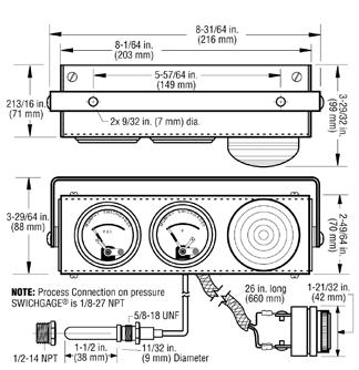


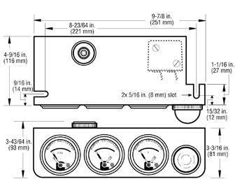

163 Dimensions WAI-2 WAI-7 WAI WAI-3 / WAI-4 WAI-8 / WAI

164 Standard Panel Assemblies and Kits Reference Guide How to Order Part Number Model Number Notes Use Model Number for Ordering WAI-2 WAI-3 WAI-4 WAI -7 WAI-8 WAI-9 WAI

 an accurate indicating gage with (2) a built-in, adjustable limit switch.")
165 Swichgage Kits for Engines WD100 Series The WD100 Series Swichgage kits provide engine monitoring that shuts down farm, construction or other engine-powered equipment when dangerous pressures or temperatures occur. The control center for each of these kits is the compact and adjustable Universal Mounting Panel. This panel holds two Swichgages and a Tattletale magnetic switch as well as a shut-down device where appropriate. Specifications Murphy Swichgage products are two-instruments-in-one: (1) an accurate indicating gage with (2) a built-in, adjustable limit switch. 518PH Tattletale magnetic switch is designed to shut down engines by operating as a circuit breaker to interrupt the ignition circuit to a distributor or to close a solenoid fuel valve on diesels. Temperature capillary tubes are 6 ft. (1.8 m) standard but can be ordered in any length. Standard Swichgage ranges*: Pressure: psi (0-689 kpa) [ bar] Temperature: 100 to 250 F (37 to 121 C) *Other ranges available on request. Kit Combinations These kits are available for virtually any engine application, any engine type or can be custom ordered to meet a specific use. 153 WD100 Series Kits Kit WD100 includes: A and B Suitable for use on distributor ignition engines or on diesels having a shutdown solenoid in the fuel pump Approximate Shipping Weight: 4.75 lbs. (2.2 kg) Approximate Shipping Dimensions: 9-3/4 x 9-1/4 x 5-3/4 in. (248 x 235 x 146 mm) Kit WD150 includes: A, B, C and E Suitable for most liquid cooled diesel engines Approximate Shipping Weight: 6.15 lbs. (2.8 kg) Approximate Shipping Dimensions: 9-3/4 x 9-1/4 x 5-3/4 in. (248 x 235 x 146 mm) sect rev. 2014/11/01 Depending upon the kit selected, the following components are supplied: A. Universal Mounting Panel which consists of: 20P oil pressure Swichgage instrument 20T temperature Swichgage instrument with 6 ft. (1.8 m) capillary, or 20TH temperature Swichgage instrument for WD175 kit 518PH Tattletale magnetic switch B. Bracket mounting bolts, washers and nuts C. CKV2336 fuel reverse flow/check valve D. PRV50 fuel pressure relief valve E. SV Series fuel shut-off solenoid valve (1/4 NPT X 1/4 NPT) Specify 12-VDC or 24-VDC Kit WD175 includes: A, B, C and E Suitable for air-cooled diesel engines; 10 mm 1.5 adaptor and special head temperature bulb. Includes SV Series fuel valve Approximate Shipping Weight: 6.15 lbs. (2.8 kg) Approximate Shipping Dimensions: 9-3/4 x 9-1/4 x 5-3/4 in. (248 x 235 x 146) Kit WD185 includes: A, B, C, D and E Suitable for engines with geardriven transfer pump. (SV Series is not required on engines with built-in shutdown in the injector pump.) Approximate Shipping Weight: 6.20 lbs. (2.8 kg) Approximate Shipping Dimensions: 9-3/4 x 9-1/4 x 5-3/4 in. (248 x 235 x 146 mm)
![Typical Wiring to Diesel Engine Special Notes: Murphy Pressure Relief Valve (model PRV50) is factory set to start opening at 25 psi (172 kpa) [1.72 bar].](/docs-images/83/87981307/images/166-2.jpg "This is done to protect the fuel filter canister from bursting due to high pressure. Install the Murphy Check Relief Valve (model CKV2336) as close as possible to the injection pump.")
166 Typical Wiring to Diesel Engine Special Notes: Murphy Pressure Relief Valve (model PRV50) is factory set to start opening at 25 psi (172 kpa) [1.72 bar]. This is done to protect the fuel filter canister from bursting due to high pressure. Install the Murphy Check Relief Valve (model CKV2336) as close as possible to the injection pump. When the CKV2336 is installed properly, it should prevent the injection pump from siphoning fuel which halts operation after the SV valve closes. Install the SV Series fuel valve as close as possible to the injection pump inlet port. All fittings must be air tight. Dimensions * Always provide proper circuit protection with fuses or circuit breakers. Rotating/Tilting Panel This panel may mount in many different positions (Swichgage instruments can be rotated and the panel tilted) that allows for instrument visibility without a difficult installation or interference with other engine equipment. How to Order To determine the kit that will suit your application, refer to descriptions. When you have selected a kit, the model number and voltage must be specified when ordering. Order oil line assembly separately. 154


167 Swichgage Shutdown Panels with Open Back for Diesel Engines WD300 Series WD300 Series The universally applicable WD300 Series panels are the ideal control solution for a wide variety of diesel engines without shut-down solenoid in the injection pump. The standard WD300 Series panel includes basic engine protection for low oil pressure and high coolant temperature. It also includes Murphy s SV Series solenoid fuel shut-off valve, (see bulletin SV-99026B). WD300LV Models For engines that have the fuel shutoff solenoid built into the injection pump. This model is also applicable to battery ignition engines. Panel Kits Include: Low lube oil pressure Swichgage instrument High coolant/temperature Swichgage instrument 117PH magnetic switch SV Series solenoid fuel shutoff valve PB128S emergency stop push button Specifications Low Lube Oil Pressure Swichgage: psi (0-689 kpa) [ bar] 1/8 NPT process connection High Coolant Swichgage: F ( C) 48 in. (1.2 m) capillary 1/2 NPT process connection 117PH Magnetic Switch SV Series Solenoid Fuel Shutoff Valve: 12 or 24 volt (specify) Approximate Shipping Weight: 8 lbs. 8 oz. (3.9 kg) Approximate Shipping Dimensions: 8.5 x 5.25 x 5.5 in. (216 x 133 x 140 mm) 155 WD300-LV Dimensions sect rev. 2015/05/
168 How to Order Options listed below. All configurations may not be available. Call your sales representative or Enovation Controls for more information. Notes: * = Standard Component or Range and is not required for ordering. See section notes if section has two parts to specify. WD300LV: Does not include an SV Fuel Valve. WD300: Includes an SV Fuel Valve. (WD = 12-volt valve and WD = 24-volt valve) If requirements are outside of the matrix, order panel with free-formed text and use the product number of the base model. 156

169 157 sect rev. 2014/11/02 Electric Gage Shutdown WDU Series Panels for Deutz 1011/2011, 912/913 and 914 Engines Deutz engines that come factory equipped with electric-switched oil pressure and temperature senders can now be outfitted with a standard line of electric gage plug-and-go panels that take the work and time out of the installation process. Two bolts mount the panel to the engine s bell housing, and the included wiring allows for fast plug-and-go assembly. Simply remove two screws and the front hinged panel drops down allowing access to all the internal components. These panels are offered in three versions to accommodate all wiring and mounting requirements for DEUTZ 1011/2011, 912/913 and 914 Engines. The panels are designed to compliment Deutz engines supplied with pre-installed factory-set electric switched senders. Protection against low oil pressure and high engine temperature is achieved with the Murphy 760A Time Delayed Magnetic Switch. A panel mounted 10 amp fuse protects the sensitive instrumentation from any over-current situation and stops the engine if blown. The Deutz pre-installed electric switched senders supply all shut-down signals directly to the Murphy 760A providing reliable and proven engine protection in harsh environments. Critical engine information is provided with Murphy s environmentally sealed, LED illuminated EG Series electric gages. Known for their reliable performance and constructed of corrosion resistive materials, these rugged gages exceed SAE J1810 standards for use in tough off-road and industrial power unit applications. A unique spin-on gage clamp keeps the gages tight even in high vibration applications. Murphy s alternator driven ATHA 4000 RPM tachometer provides accurate display of engine speed with its back-lit dial, while the digital hour meter records the elapsed engine run time. The heavy-duty key switch constructed of corrosion resistant materials and heavy gage wiring exceeds the current requirements of the starter and engine pre-heat circuit. A red lamp mounted on the front panel indicates when the pre-heat circuit is active. All components are assembled into a robust black powder-coated enclosure with text indicating key position. The plug-and-go external wire harness connects to the rear of the panel and has all the engine side connections pre-wired. The panel mounting bracket comes pre-assembled to the enclosure with three vibration isolators, making installation fast and simple. Features Pressure Gage: 0-80 PSI (0-500 kpa) Engine Temperature Gage: F ( C) Volt Meter (8-18 VDC) Tachometer/Hourmeter ( RPM) Key Switch (Heavy-Duty) Engine Preheat with Red Indicator Lamp Murphy 760A Safety Shutdown (Automatic Time Delayed for Start-up) Panel Mount Fuse Recessed and Protected Front Panel Durable Powder-Coat Finished Enclosure and Mounting Bracket Labor Saving Install Features Pre-wired External Harness (Includes all connectors and terminals) Mating connectors match Deutz Engine wiring for fast plug-and-go connection Pre-assembled: Enclosure, Rubber Isolation Mounts and Mounting Bracket Simple Bolt-on/Plug-in Installation

170 WDU0814 Dimensions (includes Enclosure, Mounting Bracket and Shock Mounts) Wiring Always provide proper circuit protection with fuses or circuit breakers. 158
171 WDU0815 Dimensions (includes Enclosure, Mounting Bracket and Shock Mounts) WDU0815 Wiring Always provide proper circuit protection with fuses or circuit breakers

172 WDU0816 Dimensions (includes Enclosure, Mounting Bracket and Shock Mounts) WDU0816 Wiring Always provide proper circuit protection with fuses or circuit breakers. 160
173 WDU0865 Wiring for Deutz 914 Tier 3 Engine Always provide proper circuit protection with fuses or circuit breakers
174 Specifications Voltage: 12 VDC Shipping Weight: 16 lb. (7.3 kg) Shipping Dimensions: 14 x 15-3/4 x 9-1/2in. (356 x 400 x 242 mm) How to Order Part Number Model and Description Notes WDU0814 Panel Number used on DEUTZ 1011/2011 Engine WDU0815 Panel Number used on DEUTZ 912/913 Engine WDU0816 Panel Number used on DEUTZ 914 Engine WDU865 Panel Number used on Deutz 914 TIER 3 engines Includes Attached Wire Harness Pigtail with engine connector, battery (+), starter, preheat and ground wires. Mounting bracket has an additional plate to accommodate specific engine mount location. Includes Loose External Wire Harness that plugs into back of panel, starter and preheat wires. Deutz-supplied engine harness also plugs into back of panel. Includes a relay housed internal to the panel for the fuel solenoid. Includes Loose External Wire Harness that plugs into back of panel, starter and pre-heat wires. Deutz-supplied engine harness also plugs into back of panel. Includes a relay housed internal to the panel for the fuel solenoid. Includes Loose External Wire Harness that plugs into back of panel, starter and pre-heat wires. Deutz-supplied engine harness also plugs into back of panel. 162

175 163 sect rev. 2014/11/04 WHB Series Swichgage Shutdown Panels for High Plains and Other Irrigation Engines The WHB Series open type panels are the industry standard for High Plains irrigation engines. These panels bolt directly to the engine flywheel housing. They include Swichgage protection for low engine oil pressure and high coolant or high oil temperature and have provision to add additional Swichgage instruments, such as a pump discharge pressure, voltage regulator, throttle cable and start button or switch. For diesel engines without shut-down solenoid in the injection pump, add a Murphy SV Series solenoid fuel shut-off valve or RP2300 series rack puller solenoid (for details visit Swichgage products are two instruments in one: (1) an accurate indicating gage with (2) a built-in, adjustable limit switch. Panel Kits include: Low Lube Oil Pressure Swichgage instrument High Coolant/ Temperature Swichgage instrument 117PH Magnetic Switch PB128S Emergency Stop Push Button Ammeter Dimensions Specifications Low Lube Oil Pressure Swichgage instrument: psi (0-689 kpa) [ bar] 1/8 NPT process connection High Coolant/Oil Temperature Swichgage instrument: F ( C) 48 in. (1.2 m) capillary 1/2 NPT process connection 117PH Ammeter: Shipping Weight: 8 lbs. 8 oz. (3.9 kg) Shipping Dimensions: 9.5 x 9 x 5 in. (241 x 229 x 127 mm)
176 How to Order Options listed below. All configurations may not be available. Call your sales representative or Enovation Controls for more information. Notes: * = Standard Component or Range and is not required for ordering. See section notes if section has two parts to specify. If requirements are outside of the matrix, order panel with free-formed text and use the 3050xxxx product number of the base model. 164


177 165 sect rev. 2014/11/04 Shutdown Panel Kits for Deutz and Other Engines W0156 and W0169 Series The W0156 and W0169 panel kits were developed specifically for air-cooled and liquid-cooled engines where a weatherproof engine panel is required. Both kits feature Swichgage protection for low engine oil pressure and high cylinder head or high oil temperature. Shock-mounted panel bolts directly to the flywheel housing or bracket of your design. These kits were originally designed for Deutz FL912 and FL913 Series engines but can be used on a variety of engines. Internal wiring mates with a standard Deutz circuit. Panel kits include: Low Lube Oil Pressure Swichgage instrument Cylinder Head/Oil Temperature Swichgage instrument 518PH Magnetic Switch Alternator failure light Ignition key switch Provisions for additional Swichgage instruments such as irrigation pump pressure or voltmeter/ ammeter etc. Provisions for tachometer Swichgage products are two instruments in one: (1) an accurate indicating gage with (2) a built-in, adjustable limit switch. A 518PH Magnetic Switch provides a closed-loop circuit to ensure proper operation at all times. The 518PH allows the system to be sensitive to open circuits, broken wires, false grounds, corrosion, loss of power and other factors which could otherwise prevent the protective controls from operating. The mounting panel is enclosed. Panel Kits are prewired, ready to install and are available for 12- or 24- VDC systems.* Dimensions (dimensions are for both panel kits) CAUTION: Certain danger to human and to equipment such as applied in a mobile or marine application may occur if some equipment is stopped without pre-warning. It is therefore, recommended that monitored functions be limited to alarm only or to alarm before shutdown in such applications. * NOTE: 12-volt kit is standard. If you require a 24-volt kit, specify when ordering
178 Typical Wiring Diagram for Deutz Specifications Always provide proper circuit protection with fuses or circuit breakers. Low Lube Pressure Swichgage: psi (0-689 kpa) [ bar] 1/8 NPT process connection 518PH Magnetic Switch: 12 or 24 volt (specify) Shipping Weight: 14 lbs. (6.4 kg) Shipping Dimensions: 14-7/8 x 14-7/8 x 6-3/4 in. (378 x 378 x 171 mm) Temperature Swichgage: Cylinder Head Temperature (W0156): F ( C), M10 x 1.5 process connection Oil Temperature (W0169): F ( C), 1/2NPT process connection (see Murphy General Catalog for optional sizes) 48 in. (1.2 m) capillary How to Order Part Number Model and Description Notes Specify Model W0156 For air-cooled engines Number W0169 For liquid-cooled engines 166

179 Swichgage Shutdown Panel Kit Models WO168 and WO241 The W0168 and W0241 panel kits are universal-fit instrument panels for most industrial engines. They include Swichgage protection for low engine oil pressure and high coolant or high oil temperature. These Panel Kits are similar the W0168 has a start/ stop key switch and the W0241 has a start push button. The Swichgage product is two instruments in one: (1) an accurate indicating gage with (2) a built-in, adjustable limit switch. A 518PH Magnetic Switch provides a closed-loop circuit to ensure proper operation at all times. The 518PH allows the system to be sensitive to open circuits, broken wires, false grounds, corrosion, loss of power and other factors which could otherwise prevent the protective controls from operating. The universal mounting panel is enclosed on all four sides with an open back. An optional back cover is available for both kits. Panel Kits are pre-wired and ready to install and are available for 12- or 24-VDC systems. Features Low Lube Oil Pressure Swichgage instrument High Coolant/Oil Temperature Swichgage 518PH Magnetic Switch Emergency stop push button Ignition key switch for start/stop (W0168) Push button for start (W0241) Ammeter Provisions for additional Swichgage controls, such as irrigation pump pressure or engine oil temperature Provisions for tachometer and throttle cable Specifications Low Lube Oil Pressure Swichgage Instrument: psi (0-689 kpa) [ bar] 1/8 NPT process connection High Coolant/Oil Temperature Swichgage Instrument: F ( C) 48 in. (1.2 m) capillary 1/2 NPT process connection 518PH Magnetic Switch: 12 or 24 volt (specify) Ammeter: Shipping Weight: 8 lbs. 8 oz. (3.9 kg.) Shipping Dimensions: 16 x 11 x 5-1/2 in. (406 x 279 x 140 mm) 167 Dimensions sect rev. 2014/11/
180 Typical Wiring Diagram How to Order Always provide proper circuit protection with fuses or circuit breakers. Part Number Model and Description Notes WO168: Panel Kit, start/stop key switch 12-volt kit is standard. If Specify Model WO168B: Panel Kit with back cover, start/stop key switch you require 24-volt kit - Number WO241: Panel Kit, start push button specify when ordering 168


181 Swichgage Shutdown Panel Kit Model WO270 The W0270 is a compact, low-profile Swichgage shutdown panel kit. It is designed to fit the following power units: Caterpillar 3054 and 3056 Perkins 1004 and 1006 Detroit Diesel 1000 Series. A universal shock-mounted bracket allows mounting on either side of the engine or on top for your power unit configurations. The kit is ready for quick, easy installation with provision for installing customer supplied ignition/start key switch. All wiring is included in the panel. This panel kit is ideal for all types of power unit applications irrigation pumps, grain dryers, compressors, generators, etc. Features Engine oil pressure monitoring Swichgage instrument (20P-F) Coolant temperature monitoring Swichgage instrument (20T-F) Voltmeter (VM12/VM24) Closed-loop 518PH Magnetic Switch Emergency stop button (PB128S) Provision for throttle cable Provision for customer supplied key switch (loom is pre-wired mount and plug-in) Dimensions 169 sect rev. 2014/11/07 Provision for optional tachometer or hourmeter (loom is pre-wired) Provision for one additional Swichgage instrument such as irrigation pump discharge pressure monitoring All items pre-wired including tachometer or hourmeter Complete external wiring harness including wiring for pre-heat and shutdown solenoid
182 Dimensions continued Bottom View How to Order Part Number Model and Description Notes Specify Model WO270: Panel Kit Number Order oil line assembly separately 170

183 ML25 Panels MurphyLink Series The MurphyLink Series ML25 Panels feature the PowerView PV25, an engine and diagnostic display in an economical and compact package. This J1939- compliant device provides electronic engine parameter data, is simple to install and matches the PowerView line of rugged displays. The PV25 can be powered by 12- or 24-volt systems. The PV25 is equipped with two push buttons to quickly access a convenient menu. In addition, a back lit graphic display and two LEDs indicate Active-fault Alarm or Shutdown status. Active and Stored Fault messages display the SPN (Suspect Parameter Number), FMI (Failure Mode Indicator) and the OC (Occurrence Count) using the SAE J1939 protocol. Features Tier 4/Stage IIIB/IV Compliant/Ready Compact J1939-compliant device for electronically controlled engines Displays up to 20 standard J1939 parameters Active and stored diagnostic trouble codes Provides enhanced visual alarm indication using bright alarm and shutdown LEDs Specifications Operating Voltage: 12/24 VDC (6.5-32VDC Minimum and Maximum Voltage) Operating Current: 850mA MAX Mounting: Rubber Isolated Shockmounts Starting Method: KeySwitch Stopping Method: KeySwitch Display: PowerView Model 25 Indication Lamps: One red, One Amber via PV25 Display Enclosure Material: Powder-Coated Cold Rolled Steel Wiring Interface: 1-Deutsch HDP 21pin Connector Throttle Method: Rocker Switch (Digital Inputs to ECU) Tier 4 Regeneration: CAN Enabled (via PV25) or Rocker Switch (via Digital Input to ECU) Operational Temperature: -40 to +158 F (-40 to +70 C) Storage Temperature: -67 to +185 F (-55 to +85 C) Box Dimensions: 15.4 X 13.4 X 8.5 (340.6 mm X mm) Shipping Weight: 9.5 lbs (4.3 kg) 171 Dimensions sect rev. 2014/11/
184 How to Order Part Number Model and Description Notes ML25-FP: PV25 flat only, PTO Ramp throttle method, 12/24 VDC Flat panel ML25: PV25 enclosed, PTO Ramp throttle method, 12/24 VDC Enclosed panel ML25-T4-FP: PV25 flat only w/ T4 switch, PTO Ramp T4 Rocker throttle method, 12/24 VDC ML25-T4: PV25 enclosed w/ T4 switch, PTO Ramp T4 Rocker throttle method, 12/24 VDC Flat panel Enclosed panel 172

185 ML50 Panels MurphyLink Series The MurphyLink Series ML50 Panels feature PVCAN gages and the PowerView PV25, an engine and diagnostic display in an economical and compact package. This J1939-compliant device provides electronic engine parameter data, is simple to install and matches the PowerView line of rugged displays. The PV25 can be powered by 12 or 24 volt systems. The PV25 is equipped with two push buttons to quickly access a convenient menu. In addition, a back lit graphic display and two LEDs indicate Active-fault Alarm or Shutdown status. Active and Stored Fault messages display the SPN (Suspect Parameter Number), FMI (Failure Mode Indicator) and the OC (Occurrence Count) using the SAE J1939 protocol. Features Tier 4/Stage IIIB/IV Compliant/Ready Compact J1939-compliant device for electronically controlled engines Displays up to 20 standard J1939 parameters Active and stored diagnostic trouble codes Analog gages Provides enhanced visual alarm indication using bright alarm and shutdown LEDs Specifications Operating Voltage: 12/24 VDC (6.5-32VDC Minimum and Maximum Voltage) Operating Current: 1.2A MAX Mounting: in. Rubber Isolated Shockmounts Starting Method: KeySwitch Stopping Method: KeySwitch Display: PowerView Model 25 Indication Gages 1) Engine Temperature 2) Engine Oil Pressure 3) Engine Speed (Analog Tachometer) Indication Lamps: One red, One Amber via PV25 Display Enclosure Material: Powder-Coated Cold Rolled Steel Wiring Interface: 1-Deutsch HDP 21pin Connector Throttle Method: Rocker Switch (Digital Inputs to ECU) Tier 4 Regeneration: CAN Enabled (via PV25) or Rocker Switch (via Digital Input to ECU) Operational Temperature: -40 to +158 F (-40 to +70 C) Storage Temperature: -55 to +185 F (-67 to +85 C) Box Dimensions: 15.4 X 13.4 X 8.5 (391 X X 216 mm) Shipping Weight: 10.5 lbs (4.8 kg) 173 Dimensions sect rev. 2014/11/
186 How to Order Part Number Model and Description Notes ML50-FP: PV25 with gages flat only, PTO Ramp throttle method, 12/24 VDC ML50: PV25 with gages enclosed, PTO Ramp throttle method, 12/24 VDC ML50-T4-FP: PV25 with gages flat only w/ T4 switch, PTO Ramp T4 Rocker throttle method, 12/24 VDC ML50-T4: PV25 with gages enclosed w/ T4 switch, PTO Ramp T4 Rocker throttle method, 12/24 VDC Flat panel Enclosed panel Flat panel Enclosed panel 174
. This basic panel contains a key switch, increment/ decrement throttle and the PowerView.")
187 ML100 Panels MurphyLink Series The MurphyLink Series ML100 Panel features the PV101-C display, which was developed to meet the needs for instrumentation and control on electronically controlled engines communicating using the SAE J1939 Controller Area Network (CAN). This basic panel contains a key switch, increment/ decrement throttle and the PowerView. This standard panel can be ordered with or without an enclosure, because all of the components are assembled to a stand-alone flat panel. Optional mounting kits are offered for the enclosure, which provide packagers and operators numerous mounting solutions to meet multiple applications. Panel designs are offered to meet the needs of specific engine models. In addition, Murphy offers standard wiring harnesses for quick plugand-go operation that interface with all the secondgeneration MurphyLink PowerView panels. The PV101 Display is a multifunction tool that enables equipment operators to view many different engine or transmission parameters and service codes. The PowerView includes a graphical, backlighted LCD screen. It has excellent contrast and viewing from all angles. The display can show either a single parameter or a quadrant display for viewing four parameters simultaneously. Diagnostic capabilities include fault codes with text translation for the most common fault conditions. The PowerView has four buttons using touchsensitive technology, which eliminates the concern for push button wear and failure. In addition, operators can navigate the display with ease. Enhanced alarm indication uses ultra bright alarm and shutdown LEDs (amber and red). The PowerView has a wide operating temperature range of -40 to185 F (-40 to +85 C), display viewing -20 to185 F (-29 to +85 C) and environmental sealing to +/- 5 PSI. Features Tier 4/Stage IIIB/IV Compliant/Ready Standard Panel Designed for Modern Electronic Engines and Equipment Applications Using SAE J1939 Controller Area Network (CAN) PowerView Model 101 Displays More Than 50 Standard SAE J1939 Parameters Broadcast by Major Engine and Transmission Manufacturers ECUs Display Active Faults and ECU-Stored Faults with Text Description on Most Common Faults for Diagnosing Equipment Malfunctions Standard Harnesses Available for Most Major Engine Manufacturers ECUs Enclosed Design or Flat Panel Option 175 Dimensions sect rev. 2014/11/
188 Specifications Operating Voltage: 12/24 VDC (6.5-32VDC Minimum and Maximum Voltage) Operating Current: 1A MAX Mounting: Rubber Isolated Shockmounts Starting Method: KeySwitch Stopping Method: KeySwitch Display: PowerView Model 101-C Indication Lamps: One red, One Amber via PV101-C Display Enclosure Material: Powder-Coated Cold Rolled Steel Wiring Interface: 1-Deutsch HDP 21pin Connector Throttle Method: Rocker Switch (Digital Inputs to ECU) TSC1 CAN Throttling (via PV101) Tier 4 Regeneration: CAN Enabled (via PV101) or Rocker Switch (via Digital Input to ECU) Operational Temperature: -40 to +185 F (-40 to +85 C) Viewable Temperature: -20 to +185 F (-29 to +85 C) Storage Temperature: -40 to +185 F (-40 to +85 C) Box Dimensions: 15.4 X 13.4 X 8.5 (391 X X 216 mm) Shipping Weight: 9.5 lbs (4.3 kg) How to Order Part Number Model and Description Notes ML100-FP: PV101 Flat only, PTO Ramp throttle Flat panel ML100: PV101 Enclosed, PTO Ramp throttle Enclosed panel ML100-T4-FP: PV101 Flat only w/ T4 switch, PTO Ramp T4 Rocker throttle ML100-T4: PV101 Enclosed w/ T4 switch, PTO Ramp T4 Rocker throttle Flat panel Enclosed panel 176

189 ML150 Panels MurphyLink Series The MurphyLink Series ML150 Panels include the PowerView PV101-C display and the M-Link PowerView Analog gages. They are part of the J1939 MurphyLink Family developed to meet the needs for instrumentation and control on electronically controlled engines communicating using the SAE J1939 Controller Area Network (CAN). The PV101 display is a multifunction tool that enables equipment operators to view many different engine or transmission parameters and service codes. The panels provide a window into modern electronic engines. The PowerView includes a graphical backlighted LCD screen. It has excellent contrast and viewing from all angles. The display can show either a single parameter or a quadrant display for viewing four parameters simultaneously. Diagnostic capabilities include fault codes with text translation for the most common fault conditions. Other components in the panels are microprocessorbased M-Link PowerView Analog Gages for displaying critical engine data broadcast by an electronic engine: engine RPM, oil pressure and coolant temperature. The ML150 Series panels are available in an enclosure or stand-alone flat panel option that can be dropped into a dash or console. This standard panel can be ordered with or without an enclosure. Optional mounting kits are offered for the enclosure, which provide packagers and operators numerous mounting solutions to meet multiple applications. Features Standard Panel Designed for Modern Electronic Engines and Equipment Applications Using SAE J1939 Controller Area Network (CAN) PowerView Model 101 Displays More Than 30 Standard SAE J1939 Parameters Broadcast by Major Engine and Transmission Manufacturers ECUs Display Active Faults and ECU-Stored Faults with Text Description on Most Common Faults for Diagnosing Equipment Malfunctions Standard Harnesses Available for Most Major Engine Manufacturers ECUs Enclosed Design or Flat Panel Option 177 Dimensions sect rev. 2014/11/
190 Specifications Operating Voltage: 12/24 VDC (8-32VDC Minimum and Maximum Voltage) Operating Current: 1.4A MAX Mounting: Rubber Isolated Shockmounts Starting Method: KeySwitch Stopping Method: KeySwitch Display: PowerView Model PV101-C Indication Lamps: One red, One Amber via PV101-C Display Enclosure Material: Powder-Coated Cold Rolled Steel Wiring Interface: 1-Deutsch HDP 21pin Connector Throttle Method: Rocker Switch (Digital Inputs to ECU) or Hand Throttle (PWM or 0-5V) TSC1 CAN Throttling (via PV101) Tier 4 Regeneration: CAN Enabled (via PV101) or Rocker Switch (via Digital Input to ECU) Operational Temperature: -40 to +185 F (-40 to +85 C) Viewable Temperature: -29 to +185 F (-20 to +85 C) Storage Temperature: -40 to +185 F (-40 to +85 C Box Dimensions: 21.5 X 13.5 X 8.5 (546 X 343 X 216 mm) Shipping Weight: 16.0 lbs (7.3 kg) How to Order Part Number Model and Description Notes ML150-FP: PV101 Flat only, PTO Ramp throttle Flat panel ML150: PV101 Enclosed, PTO Ramp throttle Enclosed panel ML150-T4-FP: PV101 Flat only w/ T4 switch, PTO Ramp T4 Rocker throttle ML150-T4: PV101 Enclosed w/ T4 switch, PTO Ramp T4 Rocker throttle ML150-ES-MT5V-FP: PV101 Flat only Stop Button, Morse 5V, PWM Morse & E-Stop throttle ML150-ES-MT5V: PV101 Enclosed Stop Button, Morse 5V, PWM Morse & E-Stop throttle ML150-T4-ES-MT5V-FP: PV101 Flat only Stop Button, Morse 5V w/ T4 switch, PWM Morse & E-Stop throttle ML150-T4-ES-MT5V: PV101 Enclosed Stop Button, Morse 5V w/ T4 switch, PWM Morse & E-Stop throttle ML150-ES-MTPWM-FP: PV101 Flat only Stop Button, Morse PWM, 0-5V Morse & E-Stop throttle ML150-ES-MTPWM: PV101 Enclosed Stop Button, Morse PWM, 0-5V Morse & E-Stop throttle ML150-T4-ES-MTPWM-FP: PV101 Flat only Stop Button, Morse PWM w/ T4 switch, 0-5V Morse & E-Stop throttle ML150-T4-ES-MTPWM: PV101 Enclosed Stop Button, Morse PWM w/ T4 switch, 0-5V Morse & E-Stop throttle Flat panel Enclosed panel Flat panel Enclosed panel Flat panel Enclosed panel Flat panel Enclosed panel Flat panel Enclosed panel 178
 QVGA monochrome LCD.")
191 ML300 Panels MurphyLink Series The MurphyLink Series ML300 Panels include the new PowerView PV300, a robust, multifunction control panel that provides advanced monitoring of electronic engines designed to meet Tier 4/Euro Stage IV emissions requirements. The model PV300-P monitors multiple engine and machine parameters on an easy-toread 3.8-inch (97 mm) QVGA monochrome LCD. The panel is capable of handling sophisticated engine diagnostics as well as basic engine alarm/shutdown with integrated throttle control. The PV300 provides monitoring of Tier 4/Euro Stage 4 compliant electronic engines, monitors multiple J1939 parameters and provides basic engine alarm/shutdown with integrated throttle control. Throttling communicates through TSC1 on the J1939 CAN network. The regeneration commands for inhibit and forced-regeneration communicate through J1939 CAN protocol. Features Tier 4/Euro Stage IV ready Superior Display Visibility Even in Bright Sunlight Back-Mounted Display for Seamless Panel Integration Integrated CAN Communication Using SAE J1939 Rugged Enclosure Using Industry Standard Deutsch Connectors Circuit Protection and Diagnostics 179 Dimensions sect rev. 2014/11/
192 Specifications Operating Voltage: 12/24 VDC (9-32VDC Minimum and Maximum Voltage) Operating Current: 1.2A MAX Mounting: Rubber Isolated Shockmounts Starting Method: KeySwitch Stopping Method: KeySwitch Display: PowerView Model 300 Indication Lamps: One red, One Amber via PV300 Display Enclosure Material: Powder Coated Cold Rolled Steel Wiring Interface: 1-Deutsch HDP 21pin Connector Throttle Method: TSC1 CAN Throttling (via PV300 Tactile Rocker) - Increment/Decrement - Idle/Run - Idle, Run 1, Run 2 Tier 4 Regeneration: CAN Enabled (via PV300 Tactile Rocker) Operational Temperature: -40 to +185 F (-40 to +85 C) Storage Temperature: -40 to +185 F (-40 to +85 C) Box Dimensions: 15.4 X 13.4 X 8.5 (391 X X 216 mm) Shipping Weight: 10.0 lbs (4.5 kg) How to Order Part Number Model and Description Notes ML300: 12/24-Volt Enclosed panel 180

193 MLC380 Panel MurphyLink Series The MurphyLink Series MLC380 Panel, engineered and built by Enovation Controls Industrial Panel Division, is a superior panel offering that includes the powerful, yet simple-to-configure PV380 1 display. This display is part of the Murphy PowerView family and provides monitoring of Tier 4/Euro Stage 4 compliant electronic engines. The PV380 monitors multiple J1939 parameters and provides basic engine alarm/shut-down information. The MLC380 panel has the ability for the software to be fully configured from the front user interface. If the default parameters set by Enovation Controls are not the desired set points, the packager or operator has the ability to change these settings. The configuration tool also allows for the splash screen to incorporate a company logo when powered on. The flexibility of the MLC380 allows for the same panel to be used across many applications. This provides the operator familiarity with the display and panel in any application. The panel utilizes industry standard Deutsch connectors and is compatible for use on the simplest mechanical engine to the most advanced, fully Specifications PV380 Display Operating Voltage: 6-36 VDC; reverse polarity protected (display only) Operating Temperature: -40 to +85 C (-40 to 185 F) Storage Temperature: -40 to +85 C (-40 to 185 F) Total Current Consumption: 10W Max (display only) Viewing Area: 3.8 (97mm) QVGA (320 x 240 pixels); monochrome transflective LCD with white LED backlight and heater Viewing Angle: ±55 horizontally; +45 / -60 vertically Enclosure: Powder-coated cold rolled steel Alarms: Red and amber warning LEDs; Set point triggered output for external piezo buzzer or shut-down relay Mating Connectors: 21 Position, Deutsch HDP SE 31 Position, Deutsch HDP SE Sealing: IP66 and 67 (Display only) Vibration and Shock: 7.86g random vibe (5-2000Hz) and ±50g shock in 3 axes (Display only) 181 sect rev. 2015/09/02 electronic Tier 4 engines, when used with the correct Murphy Industrial Harness 2 or John Deere OEM engine harnessing. This panel is available in a rugged powder-coated cold rolled steel enclosure that can be mounted on or near the engine. 1 Please see fwmurphy.com/pv380 for additional information regarding this display model. 2 Please see fwmurphy.com/mih for additional information regarding harnessing. Communications: CAN (SAE J1939) and RS-485 Modbus Languages: English Outputs (2): (1) 500 ma; switched low-side (1) 5V supply (70mA); protected Inputs (8): (4) Resistive Analog (2) 4-20mA (1) Digital Input Ground (1) Frequency (2Hz - 10KHz, 3.6VAC-120VAC) EMC/EMI: 2004/108/EC and 2006/95/EC directives EN :2001 (emission) EN :2001 (immunity) EN and EN12895 SAE J1113/2, 4, 11, 12, 21, 24, 26 and
194 Product and Mounting Dimensions MLC380 Panel inches [mm] How to Order Part Number Model and Description Notes MLC380-12V 12 Volt MLC380-24V 24 Volt Mechanical Sender Kit* Optional *Mechanical Sender Kit includes: ES2P-100 Pressure Sender ES2T-250/300-1/2 Temperature Sender MP3298 Magnetic Speed Sensor ES2F Fuel Level Sender 182
195 ML1000-4X Panel MurphyLink Series The MurphyLink Series ML1000-4X Panel, engineered and built by Enovation Controls Industrial Panel Division, is a superior panel offering which includes the powerful, yet simple-to-configure MPC-10 Controller. The MPC-10 is a general, all-purpose manual/auto start and manual/auto throttling engine controller designed with rental applications in mind. The controller is purposed primarily for applications where a wide array of inputs and outputs are not required. The MPC- 10 supports J1939 CAN protocols for electronically governed engines as well as analog sensors on mechanical engines for fault and safety shutdowns. The MPC-10 follows a standard operating sequence of 22 machine states that happen in a predetermined order. Machine states can be set to zero if not needed or adjusted to fit the application. The menu structure is incredibly versatile, with the ability to change many parameters and settings from the face without the need of a PC tool, if desired. The flexibility of the MPC-10 controller allows for the same control panel to be used across many applications. This provides the operator familiarity with the controller and control panel in any application. Specifications MPC-10 Controller Operating Voltage: 8-32VDC, reverse polarity, load dump protection Operating Temperature: -40 to +85 C (-40 to 185 F) Storage Temperature: -40 to +85 C (-40 to 185 F) Total Current Consumption: Power on in stopped state; 117 ma at 12 VDC. Power on in standby mode; 52 ma at 12 VDC. Enclosure: Polycarbonate NEMA 4X Mating Connectors: 21 Position, Deutsch HDP SE, 31 Position, Deutsch HDP SE Communications: (1) CAN J1939 (1) RS485, Modbus RTU How to Order sect. 30 & rev. 2015/09/21 The Control Panel utilizes industry-standard Deutsch connectors and is compatible for use on the simplest mechanical engine to the most advanced, fully electronic Tier 4 engines, when used with the correct Murphy Industrial Harness 1 (MIH) or John Deere OEM engine harnessing. A free-of-charge PC Configuration tool is available to allow customers to change default settings and provide three levels of passcode protection. The ML1000-4X panel can be mounted directly to the engine or engine/application cover. The enclosure has a clear door for protection from foreign debris contacting the face of the controller when desired. 1 Please contact Industrial Panel Sales for application specifics and MIH harnessing. (1) USB 2.0B for Programming Outputs (13): (3) Relays: 10A, SPDT, Form C (30 10A max.), 30 A max 85C (2) Low-side (1A) (2) High-side (1A) (1) Dedicated Alternator Excite (provides Charge Fail Fault if unable to excite alternator) Inputs (15): (5) Digital, configurable (high/low) (3) Analog, configurable (4-20 ma, 0-5 V, resistive) (1) Frequency, supporting Magnetic pickup (30 Hz - 10 khz, 2.0 VAC-120 VAC) and Engine Alternator (30 Hz - 10 khz, 4.5 VRMS - 90 VRMS) Languages: English, Spanish, German, French, Italian Dimensions: x 9.30 x 6.09 in. (259 x 236 x 155mm) (WxHxD) Part Number Model and Description Notes ML1000-4X, Polycarbonate, NEMA 4X Control Panel Engine Harness, 21 Position Connector 10 Whip Harness (3m approx.) I/O Harness, 31 Position Connector 10 Whip Harness (3m approx.) Deutsch Connector Kit, 21-pin & 31-pin, Panel Connector Kit Deutsch Connector kit, 21-pin, Panel Connector Kit, Engine Only Deutsch Connector kit, 31-pin, Panel Connector Kit, I/O Only USB Programming Harness
196 Product and Mounting Dimensions ML1000-4x Connectors Deutsch 21 pin Connector Engine Deutsch 31 pin Connector I/O PIN Function PIN Function A 1 Ignition Signal B Battery + 2 C 3 D Starter Solenoid 4 E Battery - 5 F 6 G Fuel/ECU 7 H 8 J Alternator Excite 9 Analog Input 3 K 10 L 11 M 12 N 13 Not in Auto P 14 Float Stop (Digital Input 3) R Throttle Decrement 15 S Throttle Increase 16 T Frequency Input 17 Relay 3 (Common) U J1939 CAN LO 18 Relay 3 (NC) V J1939 CAN HI 19 Relay 3 (NO) W Temperature Sender 20 Oil Level (Digital Input 5) X Pressure Sender 21 Digital Input Float Start (Digital Input 2) 24 Engine Running Signal Aux battery negative Coolant Level (Digital Input 4) 30 RS RS
197 ML2000 Panel MurphyLink Series The MurphyLink Series ML2000 Panel, engineered and built by Enovation Controls Industrial Panel Division, is a superior panel offering which includes the powerful, yet simple-to-configure MPC-20 Controller. This controller is part of the Murphy PowerCore family and was developed to meet the need of manual or automatic control whether it s starting/stopping, throttling or both. This controller also has the flexibility to be used on either mechanically or electronically governed engines supporting SAE J1939 CAN communications. The ML2000 panel has the ability for the software to be fully configured from the front user interface or PC configuration tool. If the default parameters set by Enovation Controls are not the desired set points for a factory default reset, the packager or operator has the ability to change these settings with the PC configuration tool then load with a USB thumb drive 1 and USB programming harness 1. The configuration tool also allows for the splash screen to incorporate a company logo when powered on. The flexibility of the MPC-20 controller allows for the same control panel to be used across many applications. This provides the operator familiarity with the controller and control panel in any application. The Control Panel utilizes industry standard Deutsch connectors and is compatible for use on the simplest mechanical engine to the most advanced, fully electronic Tier 4 engines, when used with the correct Murphy Industrial Harness 2 (MIH) or John Deere OEM engine harnessing. The ML2000 Series panels are available in two rugged enclosures or a stand-alone flat panel option that can be dropped into an existing panel or engine surround/ dog house. The enclosure types to choose from are powder-coated cold rolled steel or polycarbonate NEMA 4X. Optional mounting kits are offered for the sheet-metal enclosure, which provide packagers and operators numerous mounting solutions to meet multiple applications. 1 USB thumb drive and programming harness sold separately from the control panel. 2 Please contact Industrial Panel Sales for application specifics and MIH harnessing. 185 Specifications sect. 30 & rev. 2014/11/10 MPC-20 Controller Operating Voltage: 8-32VD Operating Temperature: -40 to +85 C (-40 to 185 F) Storage Temperature: -40 to +85 C (-40 to 185 F) Total Current Consumption: 18W Max without 2 2A High-sides active, 146W Max with 2 2A High-sides active Enclosure: Powder-coated cold rolled steel or polycarbonate Mating Connectors: 21 Position, Deutsch HDP SE, 31 Position, Deutsch HDP SE Shipping Weights: ML2000: 13 lbs (5.9kg) ML2000-FP: 7 lbs (3.17kg) ML2000-4X: 11 lbs (4.99kg) Communications: CAN (SAE J1939) and RS-485 Modbus Outputs (13): (2) 1A Max Low-side (2) 2A Max High-side (2) 200mA Max 5VDC (1) 0-5VDC Analog (6) 10A Max Form C Relays Inputs (15): (8) Analog, configurable as Resistive, 0-5VDC or 4-20mA (6) Digital, Configurable as Battery or Ground (1) Frequency, (2Hz - 10KHz, 3.6VAC-120VAC)
198 Product and Mounting Dimensions ML2000 ML2000-4X How to Order Part Number Model and Description Notes ML2000, Metal Control Panel ML2000-4X, Polycarbonate, NEMA 4X Control Panel ML2000-FP, Flat Control Panel ML2000, Metal Control Panel (Spanish) ML2000-4X, Polycarbonate, NEMA 4X Control Panel (Spanish) ML2000-FP, Flat Control Panel (Spanish) Deutsch Connector Kit, 21-pin & 31-pin, Panel Connector Kit Deutsch Connector kit, 21-pin, Panel Connector Kit, Engine Only Deutsch Connector kit, 31-pin, Panel Connector Kit, I/O Only Harness, ML2000, Mechanical, 10 Blunt, 21 Pos, 10 Mechanical Engine Whip Harness Harness, ML2000, I/O, 10 Blunt, 31 Pos, 10 I/O Whip Harness ML2000 USB Programming Harness, 6PIN to USB Programming Harness English Spanish 186

199 Murphy Industrial Harnesses MurphyLink Series The MurphyLink Series ML Panels are universal to all engines. The adaptation to the engines will be through the MIH Harness, which is built to the specifications of each engine manufacturer and customer. When requesting the MIH Harness, specific information will be obtained so that the correct harness may be built for your engine. Features Connect any MurphyLink Panel to Major Engine Manufacturers Engines Customizable Per Specific Customer Application and Requirement Standard 21-Pin Deutsch Connector Interface Manufactured in the USA Built to Strict Quality Standards for Long-Term Reliability How to Order 187 sect rev. 2015/08/26 Part Number Model and Description Engine MFG MIH-CA-40P-T2-ADEM3-6: CAT W/PTO MIH-CA-64P-T3-A4E2-6: Works with C4.4 & MIH-CA-70P-IT4-A4E4-6: Works with CAT C MIH-CA-70P-IT4-A4E4-6-12VDC: Works with IT4 C9.3, C13, C15, C18 (<750 hp) MIH-CA-70P-IT4-A4E4-6-24VDC: Works with IT4 C9.3, C13, C15, C18 (<750 hp) MIH-CA-70P-IT4-C4.4-12VDC: Works with only IT4 C4.4 Caterpillar MIH-CA-70P-IT4-C VDC: Works with only IT4 C MIH-CA-70P-T3-A4-6: Works with C series tier 3 except 4.4 and MIH-CA-86P-T4-C4.4-6: Works with FT4 C4.4 only MIH-CA-70P-FT4-C7.1-6: Works with FT4 C7.1 only MIH-CA-70P-T4-C9.3-C18: Works with FT4 C only MIH-CU-50P-T2-CM570-12: Works with QSM/QSX MIH-CU-50P-T2-CM570-6: Works with QSM/QSX MIH-CU-50P-T3-CM850-12: Works with QSB, QSC, QSL Cummins MIH-CU-60P-IT4-CM2250-6: Works with QSB6.7, QSL9, QSX11.9, QSX MIH-DD-30P-T3-DDECIII/DDECIV-6: Works with DDEC III/IV ECM MIH-DD-68P-T3-DDECV-6: Works with 50/60 Series, DDEC V ECM Detroit Diesel MIH-JCB-62P-T4-DCM3.3-6: Works with it4 and FT4 JCB MIH-SCANIA-8P/6P-DC-13-24V: Works with it MIH-SCANIA-8P-FT4-EMS-XPI-6: Works with FT4 Scania Table continued on next page
200 How to Order, cont. Part Number Model and Description MIH-CA-40P-T2-ADEM3-6: Works with CAT w/pto MIH-CA-64P-T3-A4E2-6: Works with C4.4 & MIH-CA-70P-IT4-A4E4-6: Works with CAT C MIH-CA-70P-IT4-A4E4-6-12VDC: Works with IT4 C9.3, C13, C15, C18 (<750 hp) MIH-CA-70P-IT4-A4E4-6-24VDC: Works with IT4 C9.3, C13, C15, C18 (<750 hp) MIH-CA-70P-IT4-C4.4-12VDC: Works with IT4 C4.4 only MIH-CA-70P-IT4-C VDC: Works with IT4 C7.1 only MIH-CA-70P-T3-A4-6: Works with C Series Tier 3 except 4.4 and MIH-CA-86P-T4-C4.4-6: Works with FT4 C4.4 only MIH-CA-70P-FT4-C7.1-6: Works with FT4 C7.1 only MIH-CA-70P-T4-C9.3-C18: Works with FT4 C only MIH-PK-94P-IT4/T4-C3.4/P854F-: Works with IOPU and ML Panel Connection MIH TO IOPU JUMPER HARNESS: Jumper Harness MIH-IOPU-CA-70P-FT4-C7.1: Not yet released MIH-IOPU-CA-86P-FT4-C4.4: Not yet released MIH-PK-94P-IT4/T4-C3.4/P854F-: Works with IOPU and ML Panel Connection MIH, extension harness, 6 feet long MIH, extension harness, 12 feet long MIH, extension harness, 20 feet long MIH, extension harness, 40 feet long Engine MFG Perkins-854 IOPU Harnesses Extension Harnesses 188


201 Marine Engine Panel Series Local and Remote 189 sect rev. 2014/11/6 Maximize the monitoring and alarm capabilities for your mechanical engine with Murphy s panel solutions designed specifically for commercial marine applications. The 100 Series and 300 Series provide the durability, reliability and functionality essential for your engine and offer a broad range of features from which to choose. Designed Specifically for Commercial Marine, Mechanical Engine Applications Full and Broad Compliment of Features and Functionality High-Quality Construction and Components Designed to Withstand the Rigors of Marine Life Local and Remote Panel Options MLP100 Indication Gages: Water Temperature (Engine Coolant Temperature) Oil Pressure (Engine Oil Pressure) Voltage (Voltmeter) Engine Speed (Analog Tachometer/ Digital Hour Meter) Inputs: Battery (+) Battery (-) Magnetic Pickup Engine Oil Pressure Engine Temperature Outputs: Engine Crank Engine Stop Signal MRP100 Indication Lamps: 5-First Out Fault Indication Lamps Utilizing Murphy s ST5 Annunciator 1-Power On Lamp Utilizing Murphy s ST5 Annunciator Indication Gages: Engine Speed (Analog Tachometer/ Digital Hour Meter) Inputs: Battery (+) Battery (-) Magnetic Pickup Remote Stop Signal Line In Warning Oil Pressure Warning Coolant Temperature Mounting: Shock Mounts Panel Material: Polycarbonate Style: Enclosed Voltage: 12-V or 24-V Max Current Draw: 13 Amps Starting Method: Key Switch Stopping Method: Key Switch or Engine Stop Button Wiring Interface: 1-Deutsch HDP 21 pin & 1 Deutsch HDP 31 pin Connectors Remote/ Local Switch: Toggle Switch for Switching Between Local and Remote Modes of Operation Outputs: Remote Start Remote Stop Signal Mounting: Countersunk Screw Holes (size 6 to 8 screws) Panel Material: Polycarbonate Style: Flat Panel Voltage: 12-V or 24-V Max Current Draw: 13 Amps Starting Method: Key Switch Stopping Method: Key Switch or Engine Stop Button Wiring Interface: 1-Terminal Block 16 Position
 Oil Pressure (Engine Oil Pressure) Voltage (Voltmeter) Engine Speed (Analog Tachometer/ Digital Hour Meter) Gear Oil")

202 MLP300 Indication Lamps: System Power Green Incandescent Lamp Water Temperature High Red Incandescent Lamp Overspeed Red Incandescent Lamp Oil Pressure Low Red Incandescent Lamp Warning Red Incandescent Lamp Indication Gages: Water Temperature (Engine Coolant Temperature) Oil Pressure (Engine Oil Pressure) Voltage (Voltmeter) Engine Speed (Analog Tachometer/ Digital Hour Meter) Gear Oil Pressure Exhaust (Pyrometer) Crankcase Pressure (Water Column Pressure) Inputs: Battery (+) Battery (-) Magnetic Pickup Engine Temperature Outputs: Engine Crank Engine Stop Signal Mounting: Shock Mounts Panel Material: Polycarbonate Style: Enclosed Voltage: 12-V or 24-V Max Current Draw: 13 Amps Starting Method: Key Switch Stopping Method: Engine Stop Push Button Wiring Interface: 1-Deutsch HDP 21 pin & 1 Deutsch HDP 31 pin Connectors Remote/ Local Switch: Toggle Switch for Switching Between Local and Remote Modes of Operation MRP300 Indication Lamps: 10-First Out Fault Indication Lamps Utilizing Murphy s ST10 Annunciator 1-Power On Lamp Utilizing Murphy s ST10 Annunciator 1-Engine Warning Red Incandescent Lamp Indication Gages: Water Temperature (Engine Coolant Temperature) Oil Pressure (Engine Oil Pressure) Engine Speed (Digital Tachometer) Gear Oil Pressure + D14 Inputs: Battery (+) Battery (-) Magnetic Pickup Remote Stop Signal Line In Warning Oil Pressure Warning Coolant Temperature Warning Gear Oil Pressure Warning Crankcase Pressure Warning Overspeed Engine Oil Pressure Engine Coolant Temperature Gear Oil Pressure Outputs: Remote Start Remote Stop Signal Mounting: Countersunk Screw Holes (size 6 to 8 screws) Panel Material: Polycarbonate Style: Flat Panel Voltage: 12-V or 24-V Max Current Draw: 13 Amps Starting Method: Key Switch Stopping Method: Engine Stop Push Button Dimmer: Local Dimmer knob (Adjustment to Gage Backlights) Wiring Interface: 1- Terminal Block 16 Position How to Order Part Number Model and Description Notes MLP100: Marine Local Panel 12-V MRP100: Marine Remote Panel 12- or 24-V MLP300: Marine Local Panel 12-V MRP300: Marine Remote Panel 12-V MLP100-24V: Marine Local Panel 24-V MRP300-24V: Marine Remote Panel 24-V MLP300-24V: Marine Local Panel 24-V 190
203 Section 40 Engine and Motor Controls Engine and Generator Controls Keystart 9620 Series Engine/Generator Controls CANstart 9630 Series Engine/Generator Controls Cascade Controller Auto-Start/Stop Automatic Engine Controller Model AEC Digital Engine Controller PowerCore MPC ML1000-4X Panel PowerCore MPC ML 2000 Panel MurphyLink Series EMS Pro Engine Monitoring System Controller EMS Pro Lite Engine Monitoring System Controller Electric Motor Controllers Murphymatic TR Series Transformer Relay Assemblies Ignition Controls IntelliSpark Ignition Controller System CD Ignition System Ignition Control Detonation Sensing Interface System Model DSI Ignition Coils Ignition Control Systems Murphy Brushless Alternators Power Supply Air/Fuel Ratio Controls AFR-1R Rich Burn Air/Fuel Ratio Control System AFR-9R Rich-Burn Air/Fuel Ratio Controller AFR-64R Rich Burn Air/Fuel Ratio Control System AFR-64L Lean Burn Air/Fuel Ratio Control System EICS Engine Integrated Control System Rack Pullers Pull/Push DC Solenoids for Diesel Engines RP Series Rack Puller for Diesel Engines Model RP Throttle Controller Murphymatic Engine Throttle Controller Model AT Clutch Controller Electric Motor Driven Clutch Operator for Engine Automation Systems
204 This Page Has Intentionally Been Left Blank 192
205 Keystart 9620 Series Engine/Generator Controls Keystart 9620 and 9621 control modules provide manual start/stop and automatic fault protection for generators, pumps and other engine-driven applications. Outputs allow control of engine fuel (energized to run), starter motor and preheat. The Keystart also has an alarm output for remote or audible warning of faults. Six LEDs and icons indicate engine status and faults. Four switch inputs (closing to negative on fault) enable automatic shutdown on engine low oil pressure, high coolant temperature and auxiliary faults. Model 9621 has a fully adjustable engine overspeed shutdown feature, configurable for either generator AC or magnetic pickup speed signals. Charge alternator excitation and a charge fail warning LED are standard. Electrical connection is by quick-connect, springclamp terminal blocks. A universal 7 to 30VDC power supply permits operation with 12 or 24VDC engine batteries, with standard engine crank-dip voltage protection. Keystarts are mounted in the front through a standard cutout and secured at the rear with quick-fit clips. Epoxy resin case encapsulation gives superior vibration/ shock resistance and environmental protection. Specifications Power Supply Operating voltage, steady state: 7 to 30VDC Operating voltage, brown out/cranking: 5VDC minimum Current consumption: <100mA Inputs Fault switch inputs: close to negative DC during fault Generator AC input (model 9621 only): VAC rms, <50 to >60 Hz nominal Magnetic pickup input (model 9621 only): VAC rms, <2000 to >6500 Hz nominal Outputs (all ratings non-reactive) Run (fuel): positive DC, NO relay contacts, 10A 24VDC Start (crank): positive DC, keyswitch contacts, 10A 24VDC Alarm: negative DC (open collector transistor), 300 ma max Speed calibration: to suit 0-1mA, 75 Ohm meter, output=0.75ma at rated engine speed. Adjustable settings Preheat timer: 0 or 10 secs, default = 0 secs Fault override timer: 2 to 20 secs (VR1), default = 10 secs Overspeed trip level (model 9621 only): 100 to 130% (VR3) of nominal calibrated speed, default = 110% (of 50 or 60 Hz) Physical Case material: polycarbonate / polyester Overall dimensions: (w x h x d): 3.8 x 3.8 x 3.7 in. (96 x 96 x 95 mm) Panel cut-out size: DIN 3.6 x 3.6 in. (92 x 92 mm) Weight: approx 0.7 lb. / 300g Operating temperature: -31 to 131 F / -35 to 55 C Electromagnetic compatibility: EN55022, class B 193 sect. 40 & rev. 2015/08/31 Typical Connections
206 Operation, Connections and Settings Front View and Operation Rear View, Connection & Settings LED Indication run (fuel) on - green preheat on - amber low oil pressure fault shutdown - red high engine temperature fault shutdown - red overspeed/aux 2 fault fault shutdown - red charge fail warning - red aux 1 fault shutdown - red 4 Position Keyswitch Off/Reset. Removes power, stops the engine and resets any O latched shut-down fault. Key is only removable in this position. Run. Activates the run output and (if enabled) the timed I preheat output. Once the engine is fully running, and after the override time, keystart immediately shuts down the engine on detection of a fault. Start/crank. Maintains the run output, and activates the start II (crank) output. Shut-down fault inputs are disabled and the fault override timer is reset. This position spring-returns to I (run) on release. Auxiliary. III Keyswitch auxiliary output, positive DC How to Order Configuration Use a 3 mm/0.1 in. flat head screwdriver for potentiometers VR1- VR3 Models 9620 and 9621: J3 & J4: preheat output timing - J4 ON: no preheat - J4 OFF, J3 OFF: preheat 10 secs fixed, unaffected by cranking - J4 OFF, J3 ON: preheat 10 second max, de-activated by cranking VR1: Fault override, 2-20 secs, clockwise to increase. Model 9621 only: J1 & J2: speed sensing source (pins 13 and 14): - both links ON for generator AC, 50/60Hz - both links OFF for magnetic pickup, Hz VR2: Speed calibration. Set J1 and J2 correctly, run engine to nominal speed, adjust VR2 to give (pin 11) calibration output of 0.75mA VR3: Overspeed, % of VR2 setting, clockwise to increase Part Number Model / Description Notes KEY9620 K2 KEY9620 (without overspeed protection) Only available from our UK office. Keyswitch Type K2, rubberized KEY 9621 (with overspeed protection, selectable AC generator or magnetic pickup sensing)* Keyswitch Type K2, rubberized Spare mounting clips (pack of 4) Spare keyswitch (K2 type), includes key Accessories / Spares Spare key (K2 type) Keystart 9620/9621 Installation Instructions Further Information *Factory default setting is for AC generator sensing, calibrated to either 50 or 60 Hz nominal. Non-standard (NS) setting options are available to order. 194
207 CANstart 9630 Series Engine/Generator Controls CANstart 9631 and 9632 modules provide operator start/stop control, panel gage driving, fault indication, and auxiliary shut-down protection for ECU-controlled, CAN bus SAE J1939 compatible engines. These compact controllers can be used with generators, pumps and other engine-driven applications. Operator control is through a four-position keyswitch. The key is common to all CANstarts and is removable only in the stop/reset position. Six LEDs and icons indicate engine/ecu status and faults. Two of these LEDs (with associated inputs) provide for auxiliary fault shutdown and charge alternator fail excitation. CANstart has two protected (positive DC) FET outputs for the control of ECU engine run and starter motor. Three additional outputs drive analog panel gages (Murphy, VDO or Datcon) based on ECU-transmitted data for engine speed, oil pressure or coolant temperature. All units include adjustable engine overspeed protection: model 9631 provides automatic overspeed shutdown for variable speed applications; model 9632 is configured for fixed-speed 1500/1800 RPM genset use. DIP switches at the rear allow set up of control and gage output options. Electrical connection is by spring-clamp terminals, including a universal 8-32VDC power supply for operation with 12 or 24VDC engine batteries. Engine cranking supply brownout protection is standard. CANstart is panel-front mounted through a standard cutout and secured at the rear with quick-fit clips. Epoxy resin case gives superior vibration/shock resistance and environmental protection. Typical Connection Specifications 195 sect. 40 & rev. 2014/10/28 Power Supply Operating Voltage, steady state: 8 to 32 VDC Operating Voltage, brownout / cranking: 5 VDC minimum Current consumption: < 100 ma Inputs CAN bus: SAE J1939 protocol, switchable 120 Ohm terminating resistor Auxiliary Shutdown (x2): close to negative DC during fault Outputs (all ratings non-reactive) Run (ECU), start (crank): positive DC (protected FET), 6A 32 VDC Alarm: negative DC (open collector transistor), 250mA 32 VDC Oil pressure gage: suitable for Murphy, VDO 5 or 10 Bar, Datcon 7 or 10 Bar. Engine temperature gage: suitable for Murphy, VDO or Datcon Tachometer: for use with charge alternator driven tachometers Adjustable Settings Model 9631 (variable speed engines) Overspeed level: RPM (50 RPM increments) or off Model 9632 (fixed speed engines/gensets) Nominal speed: 1500 or 1800 RPM Overspeed level: 1-15% of nominal speed (1% increments) or off Physical Electromagnetic capability: 2004/108/EC Case Material: polycarbonate / polyester Overall dimensions (w x h x d): 3.8 x 3.8 x 5.2 in. (96 x 96 x 131mm) Panel cutout size: DIN 3.6 x 3.6 in. (92 x 92 mm) Weight: approx. 0.6 lb / 240g Operating Temperature: -4 to 167 F / -2 to 75 C
208 Operation, Connections and Settings Front View and Operation 4 Position Keyswitch Off/Reset. Removes power, stops the engine and resets any latched shutdown fault. Run. Activates the run output and (if enabled) the timed preheat output. Once the engine is fully running, and after the override time, Keystart immediately shuts down the engine on detection of a fault. Start/crank. Maintains the run output and activates the start (crank) output. Shutdown fault inputs are disabled and the fault override timer is reset. This position spring-returns to I (run) on release. Auxiliary. Keyswitch auxiliary output, positive DC Rear View, Connection & Settings Connection 1 -DC power supply 2 +DC power supply 3 run (ECU) output, +DC, 6A max 4 start (crank) output, +DC, 6A max 5 alarm output, -DC, 250 ma max 6 charge fail (alternator WL) 7 aux 1 input, -DC to activate 8 aux 2 input, -DC to activate 9 oil pressure gage output 10 coolant temp gage output 11 tachometer output 12 CAN screen 13 CAN high 14 CAN low S1 - S5 DIP Switch Settings Note: switch S6 reserved for future use. DP1 digital potentiometer setting (with S5 above) Overspeed shutdown set point: see installation instructions for details. How to Order Part Number Model and Description Notes CST9632 K2 CST9631: Keyswitch K2 (Type 2, rubberized) Default overspeed setting is 1250 RPM. (For variable speed engines, overspeed setting range RPM.) CST9632: Keyswitch K2 (Type 2, rubberized) Default overspeed setting is 110% of 1500 or 1800 RPM (please specify). (For fixed speed engines/gensets, overspeed setting range % of 1500/1800 RPM.) Spare mounting clips (pack of 4) Spare keyswitch (K2 type), incl. key Spare key (K2 type) Non-standard (NS) settings/options are available to order. Only available from the UK office. Non-standard (NS) settings/options are available to order. Accessories and spare parts 196
209 Cascade Controller Auto-Start/Stop The Cascade controller offers automatic start and stop control with easy configuration for a broad number of applications. This auto-start controller is designed to fit any engine-driven application requiring a simple and robust automatic start and stop sequence. Pumps, compressors, grinders, power units and generators are just a few of the industrial applications for the controller. The Cascade controller is fully compatible with all major engine types. Whether you are running mechanical or J1939 engines, the controller will work with your application. Murphy offers unique features at a competitive price with the Cascade controller. Features Durability: Encapsulated to protect it against dirt, water and dust, along with a compression gasket to fully seal it to the panel. Cascade is rated NEMA4 and IP65. Low Battery Blackouts: Operates in total blackout for a minimum of two seconds. Compatibility: Accepts MPU, AC Frequency and ECU speed signals and can operate with standard and J1939 engines. Inputs and Outputs: The Cascade Inputs and Outputs are ruggedly protected and fault tolerant. J1939 Ready: Works directly with Murphy s J1939- ready PowerView gages, just plug and go. No sender is required. CD101 Cascade Configuration Tool: Allows quick setup and loading of parameters into a Murphy standard Cascade via a PC software tool. Dimensions 197 sect. 40 & rev. 2014/10/
210 Specifications Power input: 9-35VDC continuous - operates during total black out for 2 seconds minimum. Power consumption: Sleep Mode (Manual): 1mA typical; Sleep mode (Automatic): 4mA typical. Running mode (manual): 20mA typical; Running mode (Automatic): 24mA typical. Operating/Storage temperature: -40 to 185 F (-40 to 85 C) Humidity: 0-100%, non-condensing Housing: UV stabilized black polycarbonate and epoxy encapsulation. Weather tight and includes sealing gasket to keep moisture and debris out of enclosure. Properly mounted controller will maintain NEMA4 / IP65 rating of enclosure. Vibration: Rated to 6G Impact: Rated to 10G Inputs: Dedicated digital inputs for low oil pressure, high engine temperature, remote start, DC charge fail/alternator fail. Two auxiliary inputs are configurable for multiple functions. Outputs: 7 4 auxiliary, configurable (1A DC protected). 3 dedicated outputs for crank, fuel/ecu, alternator excitation Crank attempts: 3, 5, 10, Continuous Crank Rest: 5-60 seconds, adjustable Shutdown lockout time delay: 5, 10, 15, 20, 25, 30 seconds Crank disconnect speed setting: Field settable RPM (16-60Hz AC freq input). Overspeed/underspeed trip point setting: ±5 to 50% of nominal. Speed sensing inputs: Magnetic pickup (5-120VAC RMS / 0-10 khz) and AC frequency (30-600VAC RMS / Hz) CAN bus interface: Directly reads engine speed and engine status data from SAE-J1939 enabled engines MODBUS interface: In J1939 applications, drives PVA series analog gages Shipping Weight: 1 lb. (453 g) approximately Shipping Dimensions: 5.1 x 6.7 x 1.6 inch (130 x 10 x 41 mm) approximately How to Order Part Number Model and Description Notes CD101 Cascade Controller Controller CD101 Cascade Configuration Kit Accessories 198

211 Automatic Engine Controller Model AEC101 The AEC101 Automatic Engine Controller provides simple, yet sophisticated engine automation. It features basic automatic start/stop capabilities plus other features found on more advanced and expensive controllers, all in an easy-to-install panel. The AEC101 operates from 12- or 24-volt systems. It includes crank and rest cycles, sensing circuits for crank disconnect and overspeed, overcrank and re-crank on false starts. The top LED for engine running indicates when crank disconnect occurs. Four of the up to six shut-down LEDs are dedicated for low oil pressure, high engine temperature, overspeed and underspeed. Two remaining LEDs can be established for first-out shutdown indication through auxiliary inputs 1 and 2. The built-in oil pressure and water temperature Swichgage instruments provide visual indication and can be set to initiate shutdown. The electromechanical quartz-based hourmeter can record up to 9,999.9 hours. It is housed in a shock-proof case and built to be rugged and durable for a long life. The Cascade controller allows manual or automatic selection of the operation sequence. Additional features of the AEC101 are an adjustable shutdown lockout delay, engine running indication LED, advanced microprocessor technology and a convenient hat bracket design for simple engine mounting. Specifications Operating Voltage: 9-35VDC operates during total blackout for 2 seconds minimum Environmental Operating Temperature: -40 to 85 C (-40 to 185 F) Storage Temperature: -40 to 85 C (-40 to 185 F) Humidity: 0-100%, non-condensing Inputs: dedicated digital inputs for low oil pressure, high engine temperature, remote call to run, DC charge fail/alternator fail. Two auxiliary inputs are configurable for multiple functions. Outputs: (7 total): Four configurable auxiliary sinking outputs (1A DC protected), three dedicated outputs for crank, fuel, alternator excitation. How to Order 199 Dimensions MAN OFF AUTO ENGINE RUNNING ECU STATUS REMOTE START/CRANK REST LOW OIL PRESSURE HIGH ENGINE TEMPERATURE OVERSPEED UNDERSPEED OVERCRANK/START FAIL CHARGE FAIL AUXILIARY1 AUXILIARY2 LED s ON OFF sect rev. 2014/10/21 Crank Attempts: 3, 5, 10, Continuous Crank Rest: 5-60 seconds, Adjustable Shutdown lockout time delay: 5, 10, 15, 20, 25, 30 sec. Speed sensing input: Magnetic pickup (5-120VAC RMS / 0-10 khz) AC frequency (30-600VAC RMS / Hz) Crank disconnect speed setting: Field programmable RPM (16-60 Hz AC freq input) Housing: Powder-coated 14 gage cold rolled steel Shipping Weights: 7 lb. (3175 g) approximately Shipping Dimensions: 12 x 12 x 5.5 in. (305 x 305 x 140 mm) approximately Part Number Model Notes AEC
212 Sequence of Operation The following sequence is pre-programmed into the AEC101: Operation sequence with panel in Auto: When the AEC101 receives an automatic start signal, the engine will begin to crank and the Shutdown Lockout time delay will begin. The Shutdown Lockout Delay has two functions: 1) it allows the AEC101 to disregard signals from the low oil pressure and high temperature Swichgage at engine start-up, and 2) if the engine false starts, the recrank will be delayed to allow the engine to stop moving before engaging the starter. If the engine fails to start after the set number of crank and rest attempts, the AEC101 will indicate an Overcrank LED. The engine will be locked out from any further start attempts. NOTE: All shutdown conditions can be reset by pressing the OFF button followed by pressing the Auto button to initiate auto sequence. Once Crank disconnect speed is reached the Engine Running LED will turn on steady. The engine will also run at full governed speed while in operation. If the speed exceeds the Overspeed set point, the AEC101 will initiate an engine shutdown, and the Overspeed LED will turn on. The engine will be locked out from any further start attempts. If low oil pressure or high temperature conditions occur while the engine is running, the AEC101 will shutdown the engine, and the appropriate LED will turn on. The engine will be locked out from any further start attempts. NOTE: The Shutdown Lockout Delay must have expired to get a shutdown on low oil pressure or high engine temperature. Operation sequence with panel in Manual: When the Manual button on the Cascade controller is pressed, an automatic start signal is simulated. Therefore, the controller will operate the same as it does in Auto. However, it will continue to run as long as there are no signals from monitored conditions or until the Off or Auto buttons are pushed. Keep in mind, it will still shutdown the engine if a monitored condition occurs such as low oil pressure, high engine temperature or loss of speed signal. Typical Wiring Diagram NOTE: This diagram represents a typical wiring scenario and is not the schematic to the panel. Everything shown except Cascade module, 20T, 20P and Hourmeter are customer supplied. * Hourmeter + - *Always provide proper circuit protection with fuses or circuit breakers. 200


213 PowerCore MPC-10 The Murphy PowerCore MPC-10 Controller is a general, all-purpose manual/auto start and manual/ auto throttling engine controller designed with rental applications in mind. The controller is purposed primarily for applications where a wide array of inputs and outputs are not required. This is a powerful and rugged controller that supports J1939 CAN protocols for electronically governed engines as well as analog sensors on mechanical engines for fault and safety shutdowns. While reprogrammable, the MPC-10 follows a standard operating sequence. This operating sequence is a set of 22 machine states that happen in a predetermined order. Machine states can be set to zero if not needed or adjusted to fit the application. The menu structure is incredibly versatile, with the ability to change many parameters and settings from the face without the need of a PC tool, if desired. The MPC-10 is flexible in many aspects, with the ability to: use the same controller on 12VDC or 24VDC systems; assign multiple levels of passcode protection to the menu using the free of charge PC Configuration Tool; change the input sensor type for the analog inputs; use analog inputs as digital ground inputs; be mounted in all-weather environments; be customer mounted in panel of choice. Specifications Power Input: 8-32 VDC, reverse polarity and load dump protection Cranking Power Holdup: 0 VDC up to 50 ms (also good for brownout/blackout instances) Total Current Consumption: Power on in stopped state; 117 ma at 12 VDC. Power on in standby mode; 52 ma at 12 VDC. Display: 2.7 WQVGA Monochrome HR-TFT 400 x 240 Keypad: 11 Tactile Feedback Buttons LEDs: (1) Red, Shutdown, (1) Amber, Warning, (1) Green, Auto Mode or Running Loaded State Outputs: (3) Relays: 10 A, SPDT, Form C (30 10 A max.), 30 A max 85C (2) Low-side (1A) (2) High-side (1A) (1) Dedicated Alternator Excite (provides Charge Fail Fault if unable to excite alternator) Inputs: (5) Digital, configurable (high/low) (3) Analog, configurable (4-20 ma, 0-5 V, resistive) (1) Frequency, supporting Magnetic pickup (30 Hz - 10 khz, 2.0 VAC-120 VAC) and Engine Alternator (30 Hz - 10 khz, 4.5 VRMS - 90 VRMS) 201 * sect rev. 2015/09/25 *Approved by CSA for non-hazardous locations (Group Safety Publication IEC Third Edition. Products covered in this document comply with European Union electromagnetic compatibility directive 2004/108/EC and electrical safety directive 2006/95/EC. Dimensions
214 Specifications (continued) Communications: (1) CAN J1939 (1) RS485, MODBUS RTU (1) USB 2.0B for Programming Dimensions: Width: 6.57 in. ( mm) Height: 5.24 in. ( mm) Depth: 2.55 in. (64.81 mm) Mass: 1lb. 1oz. (0.5 kg) Operating Temperature: -40 F to 185 F (-40 C to 85 C) Storage Temperature: -40 F to 185 F (-40 F to 85 C) EMI/EMC: SAE J1113 Shock: ± 50G in 3 axes Connectors Vibration: Random, 7.86 Grms ( Hz), 3 axes Sealing: IP67 front and back, IP66 Panel Seal with Gasket Case: Polycarbonate/ABS Mating Connector: Deutsch Wedge Lock W12S-P012: Gray DT06-12SA-P012 Black DT06-12SB-P012 Green DT06-12SC-P012 USB 6 pin Shipping Weight: 2lbs. 7.1 oz. (1.11 kg) Shipping Dimensions: 8 x 8 x 5-11/16 in. (204 x 204 x 127mm) (WxHxD) Languages: English, Spanish, German, French, Italian Deutsch 12 pin Connector Gray Deutsch 12 pin Connector Black Deutsch 12 pin Connector Green Deutsch 6 pin Connector USB PIN Function PIN Function PIN Function PIN Function 1 Battery (+) 1 Battery (+) 1 Battery (-) 1 USB1_VBUS 2 RS485 (H) 2 Not Used 2 Battery (+) 2 USB_DP_OUT 3 RS485 (L) 3 Digital Out 2 HS 1A 3 Battery (+) Switched 3 USB_DM_OUT 4 Relay 3 NC 4 Digital Out 1 HS 1A 4 Alt Excite 4 USB_ID_OUT 5 Relay 3 COM 5 Digital Out 2 LS 1A 5 CAN (H) 5 USB_SHLD 6 Relay 3 NO 6 Digital Out 1 LS 1A 6 CAN (L) 6 USB_GND 7 Analog In 3 7 Analog In 1 7 Relay 1 NO 8 Digital In 3 8 Analog In 2 8 Relay 1 COM 9 Digital In 4 9 Digital In 1 9 Relay 1 NC 10 Digital In 5 10 Digital In 2 10 Relay 2 NO 11 Not Used 11 Frequency In 11 Relay 2 COM 12 Battery (-) 12 Battery (-) 12 Relay 2 NC How to Order Part Number Model/Description MPC-10 Controller Panel Gasket, IP66, MPC PowerCore 3X12 Position Connector Kit PowerCore 3X12 Position 3 Conn Whip Harness (1m approx.) USB Programming Harness 202

215 ML1000-4X Panel MurphyLink Series The MurphyLink Series ML1000-4X Panel, engineered and built by Enovation Controls Industrial Panel Division, is a superior panel offering which includes the powerful, yet simple-to-configure MPC-10 Controller. The MPC-10 is a general, all-purpose manual/auto start and manual/auto throttling engine controller designed with rental applications in mind. The controller is purposed primarily for applications where a wide array of inputs and outputs are not required. The MPC- 10 supports J1939 CAN protocols for electronically governed engines as well as analog sensors on mechanical engines for fault and safety shutdowns. The MPC-10 follows a standard operating sequence of 22 machine states that happen in a predetermined order. Machine states can be set to zero if not needed or adjusted to fit the application. The menu structure is incredibly versatile, with the ability to change many parameters and settings from the face without the need of a PC tool, if desired. The flexibility of the MPC-10 controller allows for the same control panel to be used across many applications. This provides the operator familiarity with the controller and control panel in any application. Specifications MPC-10 Controller Operating Voltage: 8-32 VDC, reverse polarity and load dump protected Operating Temperature: -40 to +85 C (-40 to 185 F) Storage Temperature: -40 to +85 C (-40 to 185 F) Total Current Consumption: Power on in stopped state; 117 ma at 12 VDC. Power on in standby mode; 52 ma at 12 VDC. Enclosure: Polycarbonate NEMA 4X Mating Connectors: 21 Position, Deutsch HDP SE, 31 Position, Deutsch HDP SE Communications: (1) CAN J1939 (1) RS485, Modbus RTU How to Order sect. 30 & rev. 2015/09/21 The Control Panel utilizes industry-standard Deutsch connectors and is compatible for use on the simplest mechanical engine to the most advanced, fully electronic Tier 4 engines, when used with the correct Murphy Industrial Harness 1 (MIH) or John Deere OEM engine harnessing. A free-of-charge PC Configuration tool is available to allow customers to change default settings and provide three levels of passcode protection. The ML1000-4X panel can be mounted directly to the engine or engine/application cover. The enclosure has a clear door for protection from foreign debris contacting the face of the controller when desired. 1 Please contact Industrial Panel Sales for application specifics and MIH harnessing. (1) USB 2.0B for Programming Outputs (13): (3) Relays: 10A, SPDT, Form C (30 10A max.), 30A max 85C (2) Low-side (1A) (2) High-side (1A) (1) Dedicated Alternator Excite (provides Charge Fail Fault if unable to excite alternator) Inputs (15): (5) Digital, configurable (high/low) (3) Analog, configurable (4-20 ma, 0-5V, resistive) (1) Frequency, supporting Magnetic pickup (30 Hz - 10 khz, 2.0 VAC-120 VAC) and Engine Alternator (30 Hz - 10 khz, 4.5 VRMS - 90 VRMS) Languages: English, Spanish, German, French, Italian Dimensions: x 9.30 x 6.09 in. (259 x 236 x 155mm) (WxHxD) Part Number Model and Description Notes ML1000-4X, Polycarbonate, NEMA 4X Control Panel Engine Harness, 21 Position Connector 10 Whip Harness (3m approx.) I/O Harness, 31 Position Connector 10 Whip Harness (3m approx.) Deutsch Connector Kit, 21-pin & 31-pin, Panel Connector Kit Deutsch Connector kit, 21-pin, Panel Connector Kit, Engine Only Deutsch Connector kit, 31-pin, Panel Connector Kit, I/O Only USB Programming Harness
216 Product and Mounting Dimensions ML1000-4x Connectors Deutsch 21 pin Connector Engine Deutsch 31 pin Connector I/O PIN Function PIN Function A 1 Ignition Signal B Battery + 2 C 3 D Starter Solenoid 4 E Battery - 5 F 6 G Fuel/ECU 7 H 8 J Alternator Excite 9 Analog Input 3 K 10 L 11 M 12 N 13 Not in Auto P 14 Float Stop (Digital Input 3) R Throttle Decrement 15 S Throttle Increase 16 T Frequency Input 17 Relay 3 (Common) U J1939 CAN LO 18 Relay 3 (NC) V J1939 CAN HI 19 Relay 3 (NO) W Temperature Sender 20 Oil Level (Digital Input 5) X Pressure Sender 21 Digital Input Float Start (Digital Input 2) 24 Engine Running Signal Aux battery negative Coolant Level (Digital Input 4) 30 RS RS


217 PowerCore MPC-20 Murphy s PowerCore MPC-20 is an all-purpose industrial controller that stands up to some of the harshest environments. This powerful controller is targeted for engine-driven pumps and irrigation, with the versatility to work in most engine-driven applications. The controller can be mounted in a sealed control box but is entirely sealed to meet and/or exceed an IP67 rating. Easily viewable in full-sun conditions, the MPC-20 has a large 3.8-inch monochrome transflective LCD. Interim and Final Tier 4 ISO symbols appear with engine and application information without the appearance of a cluttered screen. The MPC-20 is configurable by the user to meet the most versatile applications. The ease of initial setup of the I/O does not leave the user feeling paralyzed when an input is needed for a specific function. This allows for quicker uptime and less headache while on the manufacturing floor or in the field. Although a configuration tool is not required, it provides the ability to configure the controller s set points on the PC and save them in a file for future loading. A standard set point configuration tool is included as a free download to allow customized default settings for building application- or customer-specific configurations. The MPC-20 s design has been proven through internal and external testing including HALT (Highly Accelerated Life Testing) and third-party approvals. Specifications Display: 3.8 Monochrome LCD, Transflective, 320 x 240 QVGA with White Backlight Keypad: 11 Tactile Feedback Buttons LEDs: (1) Red, Shutdown, (1) Amber, Warning, (1) Green, Auto Mode Outputs: (2) 1A Max Low-side (2) 2A Max High-side (2) 200mA Max 5 VDC (1) 0-5 VDC Analog (6) 10 A Max Form C Relays Inputs: (8) Analog, Configurable as Resistive, 0-5VDC, 4-20mA or Digital Ground (6) Digital, Configurable as Battery or Ground (1) Frequency, (2 Hz - 10 K Hz, 3.6 VAC-120 VAC) Communications: (1) CAN 2.0B, 250 kbps, J1939 (1) RS485, MODBUS RTU (1) USB, Programming Power Input: 8-32 VDC, Reverse Polarity & Load Dump Protection 205 * sect rev. 2015/06/01 *Approved by CSA for non-hazardous locations (Group Safety Publication IEC Third Edition. Products covered in this document comply with European Council electromagnetic compatibility directive 2004/108/EC and electrical safety directive 2006/95/EC. Dimensions
218 Specifications (continued) Total Current Consumption: 18W Max without 2 2A High-sides active 146W Max with 2 2A High-sides active Dimensions: Width: 8.2 in. (208.7 mm) Height: 7.5 in. (189.7 mm) Depth: 2.3 in. (57.5 mm) Mass: 0.9 kg (2.0 lb) Operating Temperature: -40 F to 185 F (-40 C to 85 C) Storage Temperature: -40 F to 185 F (-40 C to 85 C) EMI/RFI: SAE J1113 Shock: 50G in X, Y, Z Axes Vibration: Random, 7.86 Grms (5-2000Hz), 3 Axes Sealing: IP67 Complete Controller, IP66 Panel Mount with Gasket (Minimum 14 Ga Metal Plate) Case: Polycarbonate Mating Connector: Delphi, SICMA 90 Position Shipping Weight: 2lbs. 7.1 oz (1.11 kg) Shipping Dimensions: 9.5 x 9 x 5 in. (241 x 229 x 127 mm) How to Order Part Number Model/Description MPC-20 Controller MPC-20 Controller, Spanish version Panel Gasket, IP66, MPC PowerCore 90 Position Connector Kit PowerCore 90 Position 3 ft. Conn Whip Harness Hand Crimper for PowerCore 90 Position Connector Connectors Delphi SICMA 90 Way Connector 1-30 Delphi SICMA 90 Way Connector Delphi SICMA 90 Way Connector PIN Function PIN Function PIN Function 1 Switched Power (+) 31 Power (+) 61 Power (+) 2 Ground (-) 32 Ground (-) 62 Ground (-) 3 Analog Input 1 (Resistive,0-5V,4-20mA) 33 Digital Input 1 (Power or Ground) 63 Digital Input 2 (Power or Ground) 4 Analog Input 2 (Resistive,0-5V,4-20mA) 34 Digital Input 3 (Power or Ground) 64 Digital Input 4 (Power or Ground) 5 Analog Input 3 (Resistive,0-5V,4-20mA) 35 Digital Input 5 (Power or Ground) 65 Digital Input 6 (Power or Ground) 6 Analog Input 4 (Resistive,0-5V,4-20mA) 36 Reserved 66 High-side FET 1 (2A Max) 7 Analog Input 5 (Resistive,0-5V,4-20mA) 37 Reserved 67 High-side FET 2 (2A Max) 8 Analog Input 6 (Resistive,0-5V,4-20mA) 38 Reserved 68 Reserved 9 Analog Input 7 (Resistive,0-5V,4-20mA) 39 Reserved 69 Frequency Input 10 Analog Input 8 (Resistive,0-5V,4-20mA) 40 Analog Output 70 Ground (-) 11 Reserved 41 Reserved 71 Reserved 12 RS485 Low 42 Reserved 72 CAN Low 13 RS485 High 43 Reserved 73 CAN High 14 Reserved 44 Reserved 74 Reserved 15 Reserved 45 Reserved 75 Reserved 16 USB D+ 46 USB D- 76 USB VBUS 17 USB Ground 47 USB Shield 77 USB ID 18 Relay 4 Normally Closed 48 Reserved 78 Relay 1 Normally Closed 19 Relay 4 Common 49 Reserved 79 Relay 1 Common 20 Relay 4 Normally Open 50 Reserved 80 Relay 1 Normally Open 21 Reserved 51 Reserved 81 Reserved 22 Relay 5 Normally Closed 52 Reserved 82 Relay 2 Normally Closed 23 Relay 5 Common 53 Reserved 83 Relay 2 Common 24 Relay 5 Normally Open 54 Reserved 84 Relay 2 Normally Open 25 Reserved 55 Reserved 85 Reserved 26 Relay 6 Normally Closed 56 Reserved 86 Relay 3 Normally Closed 27 Relay 6 Common 57 Reserved 87 Relay 3 Common 28 Relay 6 Normally Open 58 Reserved 88 Relay 3 Normally Open 29 Low-side FET 1 (1A Max) 59 Reserved 89 5VDC Output 1 (200mA Max) 30 Low-side FET 2 (1A Max) 60 Reserved 90 5VDC Output 2 (200mA Max) 206

219 ML2000 Panel MurphyLink Series The MurphyLink Series ML2000 Panel, engineered and built by Enovation Controls Industrial Panel Division, is a superior panel offering which includes the powerful, yet simple-to-configure MPC-20 Controller. This controller is part of the Murphy PowerCore family and was developed to meet the need of manual or automatic control whether it s starting/stopping, throttling or both. This controller also has the flexibility to be used on either mechanically or electronically governed engines supporting SAE J1939 CAN communications. The ML2000 panel has the ability for the software to be fully configured from the front user interface or PC configuration tool. If the default parameters set by Enovation Controls are not the desired set points for a factory default reset, the packager or operator has the ability to change these settings with the PC configuration tool then load with a USB thumb drive 1 and USB programming harness 1. The configuration tool also allows for the splash screen to incorporate a company logo when powered on. The flexibility of the MPC-20 controller allows for the same control panel to be used across many applications. This provides the operator familiarity with the controller and control panel in any application. The Control Panel utilizes industry standard Deutsch connectors and is compatible for use on the simplest mechanical engine to the most advanced, fully electronic Tier 4 engines, when used with the correct Murphy Industrial Harness 2 (MIH) or John Deere OEM engine harnessing. The ML2000 Series panels are available in two rugged enclosures or a stand-alone flat panel option that can be dropped into an existing panel or engine surround/ dog house. The enclosure types to choose from are powder-coated cold rolled steel or polycarbonate NEMA 4X. Optional mounting kits are offered for the sheet-metal enclosure, which provide packagers and operators numerous mounting solutions to meet multiple applications. 1 USB thumb drive and programming harness sold separately from the control panel. 2 Please contact Industrial Panel Sales for application specifics and MIH harnessing. 207 Specifications sect. 30 & rev. 2014/11/10 MPC-20 Controller Operating Voltage: 8-32VD Operating Temperature: -40 to +85 C (-40 to 185 F) Storage Temperature: -40 to +85 C (-40 to 185 F) Total Current Consumption: 18W Max without 2 2A High-sides active, 146W Max with 2 2A High-sides active Enclosure: Powder-coated cold rolled steel or polycarbonate Mating Connectors: 21 Position, Deutsch HDP SE, 31 Position, Deutsch HDP SE Shipping Weights: ML2000: 13 lbs (5.9kg) ML2000-FP: 7 lbs (3.17kg) ML2000-4X: 11 lbs (4.99kg) Communications: CAN (SAE J1939) and RS-485 Modbus Outputs (13): (2) 1A Max Low-side (2) 2A Max High-side (2) 200mA Max 5VDC (1) 0-5VDC Analog (6) 10A Max Form C Relays Inputs (15): (8) Analog, configurable as Resistive, 0-5VDC or 4-20mA (6) Digital, Configurable as Battery or Ground (1) Frequency, (2Hz - 10KHz, 3.6VAC-120VAC)
 40700501 ML2000-4X, Polycarbonate, NEMA 4X Control Panel (Spanish) 40700502 ML2000-FP, Flat Control Panel")

220 Product and Mounting Dimensions ML2000 ML2000-4X How to Order Part Number Model and Description Notes ML2000, Metal Control Panel ML2000-4X, Polycarbonate, NEMA 4X Control Panel ML2000-FP, Flat Control Panel ML2000, Metal Control Panel (Spanish) ML2000-4X, Polycarbonate, NEMA 4X Control Panel (Spanish) ML2000-FP, Flat Control Panel (Spanish) Deutsch Connector Kit, 21-pin & 31-pin, Panel Connector Kit Deutsch Connector kit, 21-pin, Panel Connector Kit, Engine Only Deutsch Connector kit, 31-pin, Panel Connector Kit, I/O Only Harness, ML2000, Mechanical, 10 Blunt, 21 Pos, 10 Mechanical Engine Whip Harness Harness, ML2000, I/O, 10 Blunt, 31 Pos, 10 I/O Whip Harness ML2000 USB Programming Harness, 6PIN to USB Programming Harness English Spanish 208

221 EMS Pro Engine Monitoring System Controller The EMS PRO is a flexible all-in-one customizable unit that meets the needs of engine-driven pumping equipment applications. The EMS PRO is a dedicated microprocessor-based, single-engine controller. It offers field-adjustable operating parameters that can be changed without the need for a computer. It is also able to support both mechanical and J1939 electronic engines. The EMS PRO has selectable auto start/stop features with several throttling options. The auto start/stop options (single contact, floats, momentary, transducer and clock) are available at the touch of a button. The transducer start/stop option includes three settings: pressure, level and temperature. In addition, there are many performance-enhancing features, all of which are available through an operator interface that is easy to learn and use. The EMS PRO is ideal for use with a remote modem or in a SCADA system offering MODBUS RTU protocol on either the RS232 or RS485 port. The EMS PRO has the ability to withstand a wide ambient temperature range, comes standard in a NEMA 4 rated enclosure and is secured by four rubber shock mounts. Inside is a backlit graphical display that is visible day or night in all conditions. Additional features include: Shut-down history file First-out shutdowns and/or alarm indicating LEDs Supports TSC1 throttle messaging Wide operating temperature range IP66 rated Internet ready utilizing MODBUS RTU with auxiliary equipment Real-time clock in 24-hour format NEMA 4 enclosure with optional clear door Communications The EMS PRO has RS485, RS232 and J1939 CAN communication ports. The standard unit uses RS485 or RS232 for MODBUS RTU. At the same time, the CAN port allows J1939 communication with the engine ECU to display engine parameters and control the throttle via TSC1, if supported by the engine. 209 Shown with optional clear door. Specifications sect rev. 2014/10/23 *Approved by CSA for Non-hazardous locations (Group Safety Publication IEC ) Operating Voltage (12 and 24 systems): 8 VDC minimum to 32 VDC maximum Environmental Operating Temperature: -40 to 176 F (-40 to 80 C) NOTE: Care should be taken when selecting the clear door option when used in applications involving sunlight exposure. Direct sunlight can cause premature component failure by allowing the sealed enclosure temperature to exceed the rated 80 C/175 F. Storage Temperature: -40 to 176 F (-40 to 80 C) Environmental Sealing: IP66 NOTE: Meets IP66 when the door is closed and latched. Relative Humidity: 60 C Standby Current: (@ 12VDC) 220mA (@ 24VDC) 255mA CAN bus: SAE J1939 compliant Enclosure: Polycarbonate NEMA 4 (UL Certified) Inputs Analog Inputs: (12) designated via program; sender/ground digital, 4-20mA, 0-5 VDC. Digital Inputs: (8) high/low Frequency: 1 optically-isolated input for speed reference, magnetic pick-up. (2VAC-50VAC RMS) Fuel Sender Input: 33 Ohm full, 240 Ohm empty Outputs Digital Outputs: (3) FET B+ (rated at 1A) Relays: 1 SPDT and 8 SPST 5 Amp pilot relays (maximum relay ground current limited to 23 amps). User Interface: (8) button membrane switch Connectors: 21 pin and 31 pin Deutsch HDP20 Series Mounting: 4 isolated.75 inch rubber shock mounts Shipping Weight: 11 lb. (5 kg.) Shipping Dimensions (all models): 15 x 15 x 11 in. (381 x 381 x mm)


222 Dimensions How to Order Part Number Description Notes EMS Pro EMS Pro with optional clear door* pin and 31-pin connector kit Deutsch HDP pin and 31-pin harness kit pin I/O harness Contact Industrial Panel Sales MIH MIH harness Accessories * Care should be taken when selecting the optional clear door when used in applications involving direct sunlight exposure. Direct sunlight can cause premature component failure by allowing the sealed enclosure temperature to exceed the rated 175 F/80 C. 210


223 EMS Pro Lite Engine Monitoring System Controller The EMS Pro Lite is a customizable pump controller designed specifically for dewatering and irrigation applications. This versatile unit supports both mechanical and J1939 electronic engines, thus eliminating the need to stock multiple controllers. A step ahead, the EMS Pro Lite is Tier 4 and Stage IIIB/IV ready. This includes displaying the current urea level % on the LCD. The operator interface is a responsive eight-button membrane keypad and backlit graphical display mounted directly to the front of a rugged NEMA 4 enclosure. A microprocessor-based controller, the EMS Pro Lite s operating parameters are field adjustable without the need for a computer. However, the EMS Pro Lite can be modified for use with a remote modem or in a SCADA system with MODBUS * RTU protocols on either an RS232 or RS485 port. EMS Pro Lite offers Auto Start/Stop with 2-Float, Transducer settings (pressure and level) or Clock start/ stop using the internal real-time clock. Throttle to Level, Pressure or Maximum RPM (desired RPM) is offered. The robust EMS Pro Lite is engineered for 12 VDC systems (8 VDC minimum to 14.4 VDC maximum) and a wide operating temperature. Dimensions 211 sect rev. 2014/10/21 *MODBUS is a registered trademark of its respective owner and is not affiliated with Enovation Controls
224 Communications The EMS Pro Lite has RS485, RS232 and J1939 CAN communication ports. The standard unit uses RS485 or RS232 for MODBUS RTU. At the same time, the CAN port allows J1939 communication with the engine ECU to display engine parameters and control the throttle via TSC1, if supported by the engine. Specifications Operating Voltage: 8 VDC minimum to 14.4 VDC maximum Relative Humidity: 95% 60 F (15.5 C) Enclosure: Polycarbonate NEMA 4 (UL/cUL listed) Shipping Weight: 7 lb. (3.2 hg) Shipping Dimensions: 12 x 12 x 10 in. (304.8 x x 254 mm Operating Temperature: -40 to 176 F (-40 to 80 C) Storage Temperature: -40 to 176 F (-40 to 80 C) Environmental Sealing: IP65 Analog Inputs: 6 analog inputs designed via program; sender/ground digital 4-20mA, 0-5 VDC Digital Inputs: 4 digital inputs High/Low (2 inputs dedicated for auto and manual states of key switch) Frequency: 1 optically isolated input for speed reference, magnetic pick-up, (2 VAC - 50 VAC RMS, 30-10kHz) Fuel Sender Input: 33 Ohm full, 240 Ohm empty. This input can also be configured for an external auxiliary shutdown. Analog Output: 4-20mA or 0.4 to 4.2 VDC (used for V throttling) Digital Outputs: 6 digital outputs; 3 FET B+ (rated at 1A), 3 Open Collector sink-to-ground 100 ma (one of these is used to pilot a relay) Communications: RS485, RS232, CAN J1939, CAN 2.0B ports How to Order Part Number Description EMS Pro Lite Accessories pin and 9-pin, 10 ft (3.048m) Whip Harness Kit for Mechanical Engines pin, 10 ft (3.048m) Whip Harness for I/O pin Connector Kit for I/O with terminals pin and 9-pin Connector Kit with terminals pin, 10 ft (3.048m) Whip Harness for Mechanical Engines pin Connector Kit with terminals for engine connector Murphy Industrial Harness: Please contact Industrial Panel Sales for application-specific harnesses for electronic engines. 212

225 Murphymatic TR Series Transformer Relay Assemblies The Murphy TR Series Transformer Relay Assemblies are electric motor controllers. Models are available for emergency shutdown, start and stop only, start and stop with emergency shutdown and combinations of the above models with time delay. All TR Series internal control circuits are completely pre-wired and relays are plug-in type to facilitate field servicing. The NEMA 1 enclosure is standard on all TR Series models. The NEMA 3 weatherproof enclosure and LC Less Case versions are optional. Murphy Swichgage instruments for pressure, temperature, level etc., can be used with the TRs for semiautomatic or totally unattended operation and control of your electric motor powered equipment. A set of normally open, dry relay contacts controlled by a 24 VAC relay coil controls the magnetic motor starter holding coil up to 480 volts. The high voltage contacts are completely isolated from the low voltage control to help reduce electrical hazards. Features Heavy-duty transformer with multiple primary taps for easy connection to most any available AC power sources. 24 VAC low voltage secondary control circuit with terminals for remote auxiliary switches. Plug-in relays have three SPDT silver cadmium oxide contacts providing long life reliability. Power relay has extra heavy silver cadmium oxide contacts rated 10 amp, 480 VAC. When TR is used with a Murphy Analog Swichgage, it allows for visual reading of operating conditions and provides an adjustable differential between high and low settings throughout the Swichgage dial range. Applications The TR Series transformer relay assemblies are ideal for controlling a variety of electric motor driven applications. They are recommended for use on saltwater disposal systems, waterflood systems and many others. Model TR-1762 used in conjunction with model OPLHC Tank Level Controller and an OPLC Series discharge pressure can completely automate a salt water disposal pump. Specifications 213 sect rev. 2014/10/22 Transformer: Primary (power supply) with triple taps for 120/240/480 VAC 50/60 Hz Secondary (control supply) 24 VAC Power Rating: 25 VA Terminal Blocks: High Voltage rated at 30 A, 600 V Low Voltage rated at 20 A, 300 V Control Relays: Plug-in, 120 V, 10 A contact rating Contacts: Power (holding): 10 A, 480 VAC, SPST Control (auxiliary): 480 VAC, 690 VA pilot duty Conduit: Top: 3/4 in. hub; Bottom 1/2 in. hole Approximated Shipping Dimensions: NEMA 1; NEMA 3; and LC Less Case: 15 x 15 x 7 in. (381 x 381 x 178 mm) Approximated Shipping Weight: NEMA 1: 18 lb. (8.16 kg) NEMA 3: 22 lb. (10 kg) LC Less Case: 14 lb. (6.35 kg)
226 TR Assemblies Models and Functions TR7207 Used for emergency shutdown of electric motors driven equipment which are manually started. Tattletale indicates shutdown and locks out power until the malfunction is corrected and the Tattletale is reset. A momentary power failure during shutdown will not void the lockout feature. For use with standard, normally open, one-wire to ground Murphy Swichgage instruments. TR7208 Same as TR7207 except used with normally closed, ungrounded Swichgage instruments which open for shutdown. TR9193 Same as TR7207 with adjustable time delay, which locks out shutdown functions for up to 10 minutes, to allow pressures and temperatures to reach normal range after start-up. TR1760 Used with electric motors or driven equipment which is started and stopped from a remote, normally open Swichgage. TR1761 Includes the same features as the TR1760 plus provisions for operating remote panel lights or audible alarms. Also includes emergency shutdown and lockout from a remote, normally open, one wire to ground Swichgage. TR1762 Same as TR1761 with adjustable time delay lockout of shutdown functions, for up to 10 minutes, during start-up. NOTE: TR1760, TR1761 and TR1762 comply with National Electrical code 1975, Article Some models have been discontinued and replaced by other models: Discontinued Replacement TR TR1760 TR TR1761 TR TR1762 To order TR assemblies use the appropriate model number Warning: Before beginning installation of this Murphy product: 1. Disconnect ALL electrical power to the machine. 2. Make sure the machine CANNOT operate during installation. 3. Follow all safety warnings of the machine manufacturer. TR1762 Always provide proper circuit protection with fuses or circuit breakers. 214
227 TR7207 TR Always provide proper circuit protection with fuses or circuit breakers. Always provide proper circuit protection with fuses or circuit breakers
228 TR1761 Always provide proper circuit protection with fuses or circuit breakers. How to Order Part Number Model and Description Notes Specify Model Number TR7207 TR7208 TR9193 TR1760 Replaces TR-5171 TR1761 Replaces TR-7159 TR1762 Replaces TR

229 IntelliSpark Ignition Controller System The IntelliSpark 32/16/8 series ignition systems are capacitive discharge, low-tension type designs. The system is capable of generating precise spark timing that improves fuel economy, load balance and ignition stability. The controller design incorporates a state-ofthe-art 16-bit microcontroller. This technology provides users with a highly flexible solution to meet their ignition needs. The user can choose from one of five methods of crankshaft sensing for a 4-stroke engine and two methods for a 2-stroke engine. Murphy s smart ignition coils used with this product incorporate a sense lead connection for real-time spark plug demand voltage measurements by the ignition controller. This allows the controller to: Measure demand on each cylinder s plug for diagnostic purposes; Automatically control the energy delivered to the smart coils to optimize spark plug life; Use the measured demand in the unique camless crank method to determine the compression stroke, eliminating the need for a camshaft sensor. Several smart coil designs are available to accommodate specific ignition requirements including: remote mount coils and plug-mounted (integral) coils, non-hazardous or CSA Class I, Div. 2 rated versions. This system also includes the Murphy PV-450 fullcolor screen display for control functions, monitoring, programming and diagnostic testing. The eight-button display includes comprehensive built-in help files and wiring information for the coil harness and a database of common engines for ease of configuration. Features Crankshaft-referenced 16-bit microprocessor based system Patented Smart Coil technology Automatic energy control Five timing reference options including camless operation Two field-adjustable timing schedules Optimized engine combustion and performance True primary and secondary diagnostics 217 Dimensions sect rev. 2015/11/
230 Specifications Power Requirements: IS-16/8: VDC (12/24 VDC nominal) 3.0 Amps max IS-32: VDC, 6.0 Amps max Note: The input current is dependent on firing rate Environment: Temperature Operating Range: -4 o to +158 o F ( 20 o to +70 o C) Enclosure Rating: IP66 with display mounted in the enclosure box; Type 4 without display mounted in the enclosure box Third Party Approvals: CSA Certified for Class I, Div 2, Groups B, C, D IS-8: Fires 8 outputs IS-16: Fires 16 outputs IS-32: Fires 32 outputs, 2 outputs can fire simultaneously Energy Storage: IS-32/16/8: 180 mj max, per tank capacitor Communications: IS-32/16/8: An auxiliary comm port is available, RS-485 interface, MODBUS protocol Note: This port has a user programmable slave ID, runs at 9600 baud or 19.2K. All parameters available can be modified in parallel using the main front panel display. Output Electrical Specifications: IS-8: Single tank capacitor IS-16: Dual, alternately fired tank capacitors IS-32: Quad, alternately fired pairs of tank capacitors Ignition Outputs are High-side firing referenced to the T pin on the output harness Note: These outputs are not ground referenced unless the T lead is grounded. Recommend careful adherence to installation instructions. Maximum Output Current Pulse Rating: 40 Amps Note: Current pulse amplitude is dependent on the coils in use and the tank capacitor voltage. IT-230 Series coils: 7 Amp 230Volts IT-150 Series coils: Volts IT-250 series coils: Volts 4/20 ma Inputs: 4/20mA A: This input retards timing (if programmed) when schedule A is active. 4/20mA B: This input retards the timing (if programmed) when schedule B is active. How to Order Part Number Model and Description Notes IS-8,Ignition Module, 8 Outputs, Without Display IS-8D,Ignition Module, 8 Outputs, With Display IS-16,Ignition Module, 16 Outputs, Without Display IntelliSpark Ignition IS-16D,Ignition Module, 16 Outputs, With Display Module IS-32,Ignition Module, 32 Outputs, Without Display IS-32D,Ignition Module, 32 Outputs, With Display Display Module, PV450NV-03-CSA-IS Cable, Remote Power 50 ft., PVW-450-PWR-50 ft. Remote Display Unit Cable, Remote Communication 50 ft., PVW-450-RS ft. NOTE: Either choose an ignition module that comes with the display built into the enclosure or order loose display and cables for remote mount. Please contact your local Murphy Sales Representative for a complete IntelliSpark Ignition System and Murphy products from Enovation Controls. A local distributor can be found at 218

231 601 CD Ignition System Ignition Control The 601 is a self-powered Capacitor Discharge (CD) Ignition System which can be installed on any large flywheel, spark-ignited engine. With electronics enginemounted in close proximity to the flywheel, the unit is powered by magnetic charging circuitry. Features and Benefits Reliable capacitor discharge circuitry High-output, self-powered electromagnetic system 30,000 volt output at low rpm Crankshaft-referenced timing Dual trigger timing One-cylinder applications Control circuitry is sealed module Self-powered, no external power required Two-year warranty Inexpensive, proven design No moving parts to wear out More timing accuracy with flywheel mounting Compatible with most large flywheel spark-ignited engines Provides power for ignition-powered panels Dimensions 219 sect rev. 2015/04/
232 Connection Diagram Trigger Coil Generator Coil Shield to White= Engine Ground Brown= Kill Lead N S N N N Charging Bar Trigger Magnet Bar Yellow Brown Yellow Brown White Green Yellow Brown White White Green to White= Trigger #1 Yellow Brown White White=Engine GND Yellow=Coil Output 1 IT230 COIL White= Engine GND G + S + Yellow= Coil Output 1 IT200 COIL Engine Flywheel Electronic Module 601 System Shown Installation Brief 1. A trigger magnet bar is fastened to the flywheel with the run magnet (deeper recessed) at the timing angle chosen for normal running. 2. A trigger coil is installed to sense the magnets and trigger ignition circuitry. 3. The ignition unit is installed on brackets in close proximity to the flywheel, at a 30 degrees more advanced than the position of the trigger magnet bar. NOTE: Detailed instructions are provided with every unit. How to Order To order, please contact your local Murphy Sales Representative for a complete 601 Series CD Ignition Control System for your specific engine type. A local distributor can be found at 220


233 221 sect rev. 2014/10/15 Detonation Sensing Interface System Model DSI - G3500 Series Caterpillar Engine The Murphy Detonation Sensing Interface System utilizes a pair of highly sensitive accelerometers to detect detonation. In the event of detonation, the DSI signals the Murphy IntelliSpark System, via 4/20 ma control signal, which responds by immediately retarding the timing thus eliminating the potentially harmful effects of continuous detonation. Features Utilizes advanced piezoelectric accelerometer sensors to provide real-time analog signal Signal is proportional in amplitude to the levels of vibration detected Sensors respond over wide range of frequencies up to 10 K Hz Retards timing to reduce vibration intensity or eliminate it entirely Sensor range g s Detect any source of vibration Benefits Easy-to-use controller interface Detects detonation tendencies at low levels before they reach greater intensity and cause engine damage Flexible controls and useful information for operators Wide bandwidth allows detection of most mechanical vibration sources including detonation Complete installation kits, wiring guidelines and sensor kits provided Specifications Power Requirements: VDC 300mA max Controller Operating Temp: -40 o F to 158 o F (-40 o C to 70 o C) Sensor Operating Temp: -40 o F to 248 o F (-40 o C to 120 o C) Sensor Frequency: Hz Sensor Sensitivity: 10mV/g 500g F. S
234 Control Inputs The 1/REV signal must be provided. Two interfaces are available for customer convenience. Option 1. MPI_ISO_1/REV-MPI_ISO_RTN: This input connects back to the IntelliSpark Isolated_ 1/REV output pair. Option 2. 1/REV_In: This interface is designed to be used directly by a mag pick sensor. It can be wired in parallel to the MPI 1/REV mag pick up. It can also be connected in parallel to a Hall-Effect sensor if in use. Control Output: Vanalog_Out: This is a 1-5 volt open-circuit output level that when terminated externally by 250 ohm becomes a 4-20 ma current signal. Note: The Murphy IntelliSpark ignition system already has an internal 250 ohm resistor across this input. Shutdown Output: This is an Open-Drain type interface. Maximum current when activated: 1.0 amps. Maximum externally applied voltage when de-activated: 100V. Panel Controls and Indicators Power On Switch. Applies 24 VDC to the electronics and sensors. The knock sensor cable should never be removed or installed with power on. Power On Indicator provides verification that power is applied. Sensor 1(2) Low Level lights: These indicators will come on when the engine is running over 400 rpm and the sensor output is below minimum level. Its an indication that the sensor is not sensing vibration levels during normal running operations. This may be due to the sensor becoming loose or the cable is removed or the engine is running at idle or unloaded when very low levels of vibration are generated. SHUTDOWN: This indicator will come on if the system detects three heavy detonation events present for three successive revolutions. The Shutdown output will activate and it can be tied into a panel or directly to a Murphy IntelliSpark Ignition system to kill ignition. SHUTDOWN RESET: After a shutdown occurs this push-button clears the shutdown indicator and de-activates the shutdown output for subsequent start-up. Internal indicators: Flashing amber led indicates firmware is operating normally Applications: Any Caterpillar 3500 series engine. How to Order Please contact your local Murphy Sales Representative for a complete System and Murphy products from Enovation Controls. A local distributor can be found at 222
235 223 sect rev. 2015/09/09 Ignition Coils Ignition Control Systems The ignition coil is one of the most critical components of any ignition system. When properly matched to the ignition controller s output, the ignition coil ensures optimum performance and reliability. Murphy Smart Coils are patented and are used with IntelliSpark Control Technology to provide real-time diagnostics and prognostics. Also offered are coils for direct replacement of Altronic coils. All Murphy coils are manufactured with the highest quality of construction for long life durability. A variety of coils are offered to meet specific application requirements as listed below. IT-250FM Smart Coil Flange Mount Coil CSA Approved - CI. I, Gr. D, Div. 2 Duration: kv IT-230FM Smart Coil Flange Mount Coil CSA Approved - CI. I, Gr. D, Div. 2 Duration: kv ITX-230RM Smart Coil Remote Mount Coil CSA Approved - CI. I, Gr. D, Div. 2 Duration: kv ITX-250-6; Smart Coil Integral Coils CSA Approved - CI. I, Gr. D, Div. 2 Duration: kv IT Smart Coil Open Coil, Non-Hazardous Duration: kv IT Smart Coil Open Coil, Non-Hazardous Duration: kv ITX-150-6; Length Length Smart Coil 6 in. Integral Coil CSA Approved - CI. I, Gr. D, Div. 2 Duration: kv ITX-250RM SmartCoil Integral Coil CSA Approved - CI. I, Gr. D, Div. 2 Duration: kv
236 Murphy Ignition Coils Direct Replacement to Altronic Coils ITX-200RM Remote Mount Coil (direct replacement to *Altronic S) CSA Approved - CI. I, Gr. D, Div. 2 Duration: Standard ITX-170-6; -10; length (replaces *Altronic A) 10 length (replaces *Altronic B) 12 length (replaces *Altronic C) CSA Approved - CI. I, Gr. D, Div. 2 Duration: Standard IT-200FM Flanged Coil (replaces *Altronic ) CSA Approved - CI. I, Gr. D, Div. 2 Duration: Standard IT-200 Blue Unshielded Epoxy Coil (replaces *Altronic ) Duration: Standard IT-200LFM Flanged Coil (replaces *Altronic ) CSA Approved - CI. I, Gr. D, Div. 2 Duration: Long How to Order IT-200L Red Unshielded Epoxy Coil (replaces *Altronic ) Duration: Long *Altronic is registered trademark of Altronic Inc. Part Number Model Notes IT-250FM IT IT-230FM IT ITX-230RM Smart Coil ITX-150-6, 6 inch length ITX , 12 inch length ITX , 12 inch length ITX-250RM ITX-200RM ITX-170-6, 6 inch length ITX , 10 inch length ITX , 12 inch length Direct replacement IT-200FM of Altronic coil IT-200 Blue IT-200LFM IT-200L Red 224

237 Murphy Brushless Alternators Power Supply Murphy Ignition Systems are optimized with power supplies utilizing Murphy high-quality brushless alternators. Designed for long-lasting durability with no moving electrical components theses devices are ideal for all industrial applications and are certified for hazardous duty locations and field proven. Features No brushes, no brush springs One moving part, no moving electrical parts One-piece bearing housing, 4.5 or 9.5 inch brackets available Permanent bearing alignment Oversize lubrication reservoir Glass Filled TFE Fluorocarbon Seal (Teflon) Air-cooled 7.3 diameter advanced design Benefits Strong, compact reliable power Exceptional bearing life Simple inspection and maintenance procedures 24-VDC, rated to 80 amp, 5,000 rpm CSA approval rated to 60 amp, 3,600 rpm Bi-directional rotation Specifications Rated Amperes: 80 Rated Amperes: 5000 Preset Volt Range: Full Load 28.0 Preset: 27.5 Field Amperes: 4.5 Typical Rotation: Bi-Directional Shaft Diameter (Pulley): 7/8 inch nominal Voltage Regulator: Integral - Adjustable - Self Exciting Wiring Connections: B+, B-, Ground Rectifier Diode Construction: Individually Replaceable Rectifier, Rated Capacity: 225 Amperes *CSA International Certification RPM Dimensions in. (53 mm) 1.1 in. (28 mm) 0.88 in. (114 mm) dia. 12 in. (305 mm) 4.5R in. (114 mm) 7.3 in. (186 mm) diameter 4.5R in. (114 mm) 4 in. (102 mm) sect rev. 2015/09/ inch Diameter Model HZ24 Shown with optional bracket 1.5 in. (38 mm) Atlernator Shaft and Woodruff Key 15 ft of wire

238 Brushless Alternators Wiring Diagram Output Amperes at RPM Ranges For 7.3 inch diameter, single ended, 80 amp alternator to self-excited voltage regulator, all voltages. For use in Class I, Div. 2, Hazardous Areas. 120 ALTERNATOR FRAME TO EARTH GROUND NEGATIVE POWER OUTPUT POSITIVE POWER OUTPUT AC AC AC VOLTAGE REGULATOR (-) (+) (F) (-) (+) FIELD COIL Output Amperes STATOR 20 WIRE COLOR CODES AC POS NEG FLD CHASSIS GROUND WHITE RED BLK BLUE GREEN Alternator RPM X 100 How to Order Part Number Model and Description Notes HZ24, 7.3 inch diameter, air-cooled, belt or direct driven 24 Volt Alternator bracket, 4 1/2 in. universal mounting Alternator bracket, 9 1/2 in. universal mounting 226
239 AFR-1R Rich-Burn Air/Fuel Ratio Control System The AFR-1R is the simplest to use rich-burn engine, single set point air/fuel ratio control system available. The system is designed to maximize the efficiency of a 3-way catalyst by maintaining the proper air/fuel ratio. Maintaining the correct air/fuel ratio to enhance the performance of your catalytic converter shouldn t be that hard, and it s not if you choose the right equipment. The Murphy AFR-1R features a single pre-catalyst set point target to optimize the catalysts performance. And when activating the optional post-catalyst set point target, the AFR-1R monitors the catalyst performance and adjusts the air/fuel ratio to maintain and prolong the catalyst performance. The system includes the Murphy PV450 fullcolor graphical user interface for control functions, monitoring, programming and diagnostic displays. The eight-button display includes comprehensive built-in help files for added operator convenience. The Enovation Controls AFR-1R air/fuel ratio controller represents cutting-edge technology in many areas: hardware, microprocessor power, control system software, operator interface options, adaptability to variable engine conditions and control requirements, software upgrade capability, in addition to comprehensive on-board diagnostics system (OBD). Technical Features Designed for low horsepower gas fueled, carbureted rich-burn industrial engines. Microprocessor-based controller with a single set point. Set point and operation done entirely through the full-color graphic display, enclosure or remote mounted. Post catalyst, oxygen sensor input for real-time adaptation to changing catalyst performance (post catalyst sensor is optional). Pre and post catalyst thermocouple input for catalyst over temperature protection (ungrounded Type K thermocouples, optional). Pre and post catalyst differential temperature displayed. Separate alarm and shut-down dry-contact relays for flexibility in setup and operation. High-speed full-authority butterfly fuel control valves for quick response time. (available) Proportional solenoid fuel control valves for auxiliary fuel control (available) 227 Dimensions sect rev. 2015/09/
240 Technical Features (continued) Heated exhaust gas oxygen sensors for optimum AFR control. NEMA 12 enclosure, 10 in. W x 13 in. H x 5 in. D. 24 VDC standard with optional 12 VDC configuration. CD ignition input for engine speed reference with optional magnetic pickup input. Upgradeable to command multi-set point targets and accept additional end devices. How To Order Options listed below applies to all Air/Fuel Controllers. All configurations may not be available. Call your sales representative or Enovation Controls for more information. AFR Model Number Strategy AFR-PD-R-1R-20-FA50-LC HARDWARE Application End Devices AFR-PD-R 1 R 2 0 FA50 LC 1 Model 2 # of Target Setpoints 3 Control Type 4 # of Banks 5 Post Cat Sensor 6 Type of Valve 7 Kit Type AFR-ND-R AFR, No Display, HEGO Controller 1 Qty. 1 R RICH BURN 1 Single 0 None TK2 Blank Standard Kit w/enclosur AFR-WD-R AFR, With Display, HEGO Cotroller 9 Qty. 9 2 Dual 1 Yes TK4B LC "Less Case", No Enclosu AFR-ND-L AFR, No Display, Wideband Controller 64 Qty OR IF LEAN BURN - TK6B for Panel Mount AFR-WD-L AFR, With Display, Widband Controller L LEAN BURN 1 1 Fuel Ctrl Valve 1 1 UEGO Sensor TK10 AFR-PD-R AFR, With Powerview Display, HEGO Cotroller 2 2 Fuel Ctrl Valve 2 2 UEGO Sensor TK11B AFR-PD-L AFR, With Powerview Display, Widband Controller FA25 (uses FL-25) FA50 (uses FL-50) 228


241 AFR-9R Rich-Burn Air/Fuel Ratio Control System The AFR-9R is the right choice when searching for the simplest to use load following air/fuel ratio control system. The system is designed to maximize the efficiency of a three-way catalyst by maintaining the proper air/fuel ratio over varying engine loads, speeds, fuel quality, ambient temperatures and barometric pressure. This is done without operator intervention after the initial program setup. The AFR-9R features nine set point targets based on a combination of three RPM settings and three manifold pressure settings and includes three valve default position settings. As your engine s load and/or speed change, the AFR-9R anticipates (feed-forward control) and corrects the air/fuel ratio to optimize catalyst performance. The system includes the Murphy PV-450 fullcolor graphical user interface for control functions, monitoring, programming and diagnostic displays. The eight-button display includes comprehensive built-in help files for added operator convenience. The Murphy AFR-9R air/fuel ratio controller represents cutting-edge technology in many areas: hardware, microprocessor power, control system software, operator interface options, adaptability to variable engine conditions and control requirements, software upgrade capability, in addition to comprehensive onboard diagnostics system (OBD). Technical Features Set point and operation done entirely through the full-color graphic display, enclosure or remote mounted Designed for wide range of horsepower, gas fueled, carbureted rich-burn industrial engines Microprocessor-based controller with nine air/fuel set points Available with either the non-intrusive fuel enrichment strategy or the in-line fuel authority control strategy High-speed full-authority butterfly fuel control valves for quick response time. (available) Proportional solenoid fuel control valves for auxiliary fuel control (available) Map sensor to measure variances in manifold air pressure 229 Dimensions sect rev. 2015/09/
 ungrounded Type K thermocouple Separate alarm and shut-down dry-contact relays for flexibility in setup and operation Heated")

242 Technical Features (continued) Post catalyst, oxygen sensor input for real-time adaptation to changing catalyst performance (post catalyst sensor is optional) Pre and Post catalyst differential temperature displayed when using an (optional) ungrounded Type K thermocouple Separate alarm and shut-down dry-contact relays for flexibility in setup and operation Heated exhaust gas oxygen sensors for optimum Air/ Fuel Ratio control 12 / 24 VDC Magnetic pickup or CD ignition input for engine speed operating reference Upgradeable to accept additional end devices How To Order Options listed below applies to all Air/Fuel Controllers. All configurations may not be available. Call your sales representative or Enovation Controls for more information. 230

243 AFR-64R Rich Burn Air/Fuel Ratio Control System A lot of control in a single package: The AFR-64R air/ fuel ratio controller monitors ambient changes, reacts with precision and diagnoses potential problems before they become costly. Emissions Compliance: The AFR-64R precisely tracks the air/fuel mix to maintain targeted emissions levels regardless of variance in load, ambient air temperature or fuel composition. Flexibility: The AFR-64R controller stores up to 64 load-specific air/fuel set points and automatically tracks engine load changes based on engine RPM and manifold air pressure. Cost Savings: Pinpoint performance problems as soon as they occur misfires, engine valve issues and more to cut the costs of maintenance, downtime, labor and replacement parts. Whether you need better emissions compliance, engine prognosis/diagnosis and trouble-free equipment life, the AFR-64R helps maximize the efficiency of the engine and its three-way catalytic converter. Technical Features Fast, easy, low-cost installation Fits virtually any gas-fueled, carbureted, rich-burn industrial engine with (or without) a catalytic converter Windows -based platform compatible with most computers Software can be installed on laptop, PC or network Comprehensive 38-fault diagnostics, including continuous oxygen sensor health monitoring Data plotting for easy, accurate troubleshooting Separate alarm and shut-down dry contact relays Pre-catalyst closed loop, exhaust oxygen feedback control Post-catalyst exhaust oxygen feedback; cascade control for fast, real-time adaptation to changing catalyst performance Variable set-point for pre-catalyst and post-catalyst exhaust oxygen control for real-time response to varying engine loads Up to 64 load-specific air/fuel set points to map your engine Catalyst temperature monitoring for catalyst over temperature protection Drives up to two control banks for operation on V type engine configurations High-speed full-authority butterfly fuel control valves for quick response time. Dimensions 231 sect rev. 2015/09/
244 Technical Features - continued Multiple valve control options: Full Authority Valve controls all engine fuel via system- controlled butterfly valve Trim Fuel Valve adds supplemental fuel to the air intake via system-controlled proportional fuel valve Full-color Graphic Display - optional, enclosure or remote mounted RS-485/MODBUS communications support for high-speed How To Order Options listed below applies to all Air/Fuel Controllers. All configurations may not be available. Call your sales representative or Enovation Controls for more information. AFR Model Number Strategy AFR-PD-R-64R-21-FA50-LC HARDWARE Application End Devices AFR-PD-R 64 R 2 1 FA50 LC 1 Model 2 # of Target Setpoints 3 Control Type 4 # of Banks 5 Post Cat Sensor 6 Type of Valve 7 Kit Type AFR-ND-R AFR, No Display, HEGO Controller 1 Qty. 1 R RICH BURN 1 Single 0 None TK2 Blank Standard Kit w/enclosur AFR-WD-R AFR, With Display, HEGO Cotroller 9 Qty. 9 2 Dual 1 Yes TK4B LC "Less Case", No Enclosu AFR-ND-L AFR, No Display, Wideband Controller 64 Qty OR IF LEAN BURN - TK6B for Panel Mount AFR-WD-L AFR, With Display, Widband Controller L LEAN BURN 1 1 Fuel Ctrl Valve 1 1 UEGO Sensor TK10 AFR-PD-R AFR, With Powerview Display, HEGO Cotroller 2 2 Fuel Ctrl Valve 2 2 UEGO Sensor TK11B AFR-PD-L AFR, With Powerview Display, Widband Controller FA25 (uses FL-25) FA50 (uses FL-50) 232
245 AFR-64L Lean-Burn Air/Fuel Ratio Control System The AFR-64L air/fuel ratio controller provides stateof-the-art engine control in one simple, easy-to-use product. Automatic Operation: No operator intervention needed the AFR-64L controller automatically tracks multiple factors, including engine load, tailpipe emissions and more, then precisely adjusts the air/fuel mix to maximize fuel efficiency, minimize engine emissions, improve engine performance and reduce maintenance costs. Emissions Compliance: The AFR-64L controller optimizes the lean-burn air/fuel mix to maintain targeted emissions levels over varying engine loads, speeds, fuel quality and ambient conditions. Cost Savings: Pinpoint performance problems and avoid detonation. The AFR-64L controller s advanced troubleshooting and diagnostics cover 76 critical operating parameters, allowing the operator to cut the costs of maintenance, labor, downtime and replacement parts. Take control over your engine needs engine diagnostics, emissions control, fully automatic operation the AFR-64L does it all for you. Technical Features Fast, easy, low-cost installation Fits virtually any lean-burn, spark-ignited, carbureted natural-gas industrial engine Windows-based platform compatible with most computers Software, upgrades and documentation available on disk or online High-speed full-authority butterfly fuel control valves for quick response time Comprehensive 76 fault diagnostics Data plotting for easy, accurate troubleshooting Separate alarm and shut-down dry contact relays Closed loop, exhaust oxygen feedback control Variable set point for exhaust oxygen control delivers real-time response to varying engine loads and transients perfect for generator-sets and other high-variance applications Catalyst temperature monitoring to protect the catalyst from engine fueling malfunctions Dimensions 233 sect rev. 2015/09/

246 Technical Features - continued Open loop/feed forward control combined with closed loop exhaust gas oxygen sensor feedback and a super fast-acting fuel control valve Allows for rapid response to engine load changes Vital for generator sets and other applications with severe engine load variations Helps maintain compliance even in the event of an oxygen sensor failure Drives up to two control banks for operation on V type engine configurations Fast-acting Full-Authority Fuel Control Valve controls all fuel delivered to the engine Full-color Graphic Display - optional, enclosure or remote mounted RS-485/MODBUS communications support for high-speed data transmission How To Order Options listed below applies to all Air/Fuel Controllers. All configurations may not be available. Call your sales representative or Enovation Controls for more information. 234

 - in one package, saving you money and man-hours associated with the installation and setup of separate engine components.")
247 EICS Engine Integrated Control System Optimizing your engine s performance and maintaining emission compliance is easier than ever with the Murphy Engine Integrated Control System (EICS). It is a complete integration package pre-calibrated specifically for your engine model. EICS combines key components - ignition system (powered by Murphy s IntelliSpark Ignition technology), air/fuel control, speed governing, interface and diagnostics, sensors, harnesses, catalyst and engine control unit (ECU) - in one package, saving you money and man-hours associated with the installation and setup of separate engine components. The EICS has been pre-configured for your convenience, ensuring your engine will run at optimum performance without the need for manual field adjustments. Its D-EPR valve accommodates wide variations in fuel composition and speed/load ranges, maintaining efficiency with load following technology for even the toughest gas lift applications. In addition, the EICS eliminates the need for pretest site visits by maintaining emissions - saving you time and money. With EICS you can be certain your site will pass required testing, like Quad J testing, without the need for pretesting to get dialed in. Features An OEM approach to an after-market application Two packages available: performance/efficiency package, optional emissions package (includes catalyst) One unit, three integrated functions - CD Ignition, air/fuel control and electronic governing speed control Pre-calibrated and dyno tested for specific engine models Advanced electronic air-fuel ratio control Lightning fast response to engine speed/load variations and fuel quality changes Murphy s IntelliSpark Ignition Coils for expanded engine diagnostics and dynamic spark adjustment Graphical color user interface Data sharing via MODBUS RS485 Data logging 235 Benefits sect rev. 2015/11/10 Integrated system = simplified installation compared to separate components The integrated approach makes more advanced diagnostics possible No more setup of generic boxes - EICS is engine specific No more dialing in - it s pre-calibrated Optimization of your engine s performance Maintains emissions compliance between testing - no tweaking necessary Eliminates magneto failures and premature spark plug changes Reduces engine failure diagnostic time Reduces costs associated with the engine s operation


248 How To Order Step 1 - Pick the EICS System based on your engine model An EICS System is Available for Engine Models Arrow VRG330 and VRG330CF Caterpillar G3300 Series Caterpillar G3406 Cummins G5.9 Cummins G8.3 Cummins Engine KTA19GC Kits are available with magneto conversion for older engines. Kits are also available with shielded ignition components. Step 2 - Determine display variant Every EICS Engine Kit Requires One Display - Choose One Variant Below P/N In Panel Mount Display Kit, Display + EICS Pigtail + RS485 Pigtail P/N Remote Mount Display Panel with Switches, in Enclosure Step 3 - Add optional hardware if desired Add Optional Emissions Package: Emissions kits are available for each engine. To order, contact your Murphy sales representative. To Add Optional Suction/Discharge Pressure Based Speed Control: Order the key below and add a standard Murphy PXT 4-20ma Pressure Sensor to complete P/N Suction Control/Discharge Control Software Key (requires Murphy PXT sensor) Step 4 - Generator controls The EICS works with generator controls. To check compatibility contact your Murphy sales representative. Contact your Murphy sales representative: To purchase products and systems To view a full list of supported engine models To let us know which engine models you would like to see mapped next Contact your Murphy sales representative at Diagram of System Overview 236

249 237 sect rev. 2014/12/04 Pull/Push DC Solenoids for Diesel Engines RP Series The Murphy Push/Pull DC Solenoids provide single unit versatility for engine applications, such as shutdown. One solenoid offers pull/push operation. The RP Series has no internal switches, reduces coil burnout and reduces adjustments while boosting reliability. The solenoid offers high force in its small size. It can be used with most engines start systems. A choice of two models and two voltages is available. All models come complete with return spring and rubber seal boot. An SD85 Solenoid Drive Time Delay is also available to greatly reduce possibility of coil burnout and to facilitate low current-piloted operation. Basic Models Models RP2307B and RP2308B give a full 1 in. (25 mm) stroke at 11 pounds (49 N) and hold up to 27 pounds (120 N) at full voltage, continuous duty. They will operate at any stroke less than maximum; see chart below. Models RP2309B and RP2310B can pull 17 pounds (75 N) with a 1-1/2 in. (38 mm) stroke. They hold up to 35 pounds (155 N) at full voltage, continuous duty. See chart below for holding force at any stroke less than maximum. RP2309B & RP2310B RP2307B & RP2308B SD85 Solenoid Drive Time Delay The SD85 is used when the solenoid is duty cycled for short time periods such as two-position throttle operation. It also provides enhanced operational control for normal on-off applications. Using the SD85 ensures the energize coil is only powered for one to two seconds with each operation. If the plunger does not seat in that time, it is highly unlikely it will seat. The SD85 activates both coils of the solenoid for a short time then de-energizes the Energize coil. The Hold-in coil is energized as long as the signal to the SD85 is active. This ensures long life of the RP solenoid. Input voltage: 8 to 30 VDC. See chart below for current ratings. Watts Power/Cold Force in Pounds at 100% Voltage/Inches Stroke Solenoid Model Number Max Stroke In. (mm) Power in Watts Hold Coil Energize Coil RP2307B 1 (25) RP2308B 1 (25) RP2309B 1-1/2 (38) RP2310B 1-1/2 (38) Force* in Pounds [Kilograms] at 100% Voltage Stroke in Inches (Millimeters) Hold Continuous 1/8 (3) 1/4 (6) 1/2 (13) 3/4 (19) 1 (25) 1-1/4 (32) 1-1/2 (38) 25 [11.34] <13> [5.90] 27 [12.25] <15> [6.80] 32 [14.52] <19> [8.62] 35 [15.88] <20> [9.07] 22 [9.98] <12> [5.44] 25 [11.34] <14> [6.35] 30 [13.61] <18> [8.16] 34 [15.42] <19> [8.62] 21 [9.53] <11> [4.99] 23 [10.43] <13> [5.90] 27 [12.25] <16> [7.26] 31 [14.06] <17> [7.71] 17 [7.71] <10> [4.54] 19 [8.62] <12> [5.44] 22 [9.98] <14> [6.35] 26 [11.79] <15> [6.80] 14 [6.35] <8> [3.63] 15 [6.80] <9> [4.08] 18 [8.16] <11> [4.99] 22 [9.98] <12> [5.44] 10 [4.54] <6> [2.72] 11 [4.99] <7> [3.18] 13 [5.90] <9> [4.08] 17 [7.71] <9> [4.08] 8 [3.63] <6> [2.72] 12 [5.44] <7> [3.18] 6 [2.72] <4> [1.81] 7 [3.18] <4> [1.81] * Forces shown are without return spring. Forces shown < > are with return spring. Forces shown in [ ] are in kilograms. To determine the operating current, divide the power (watts) indicated in the above table by the applied voltage. Solenoids will operate at any stroke less than maximum
 Stroke Solenoids (70 F/21 C rise above ambient) 120 F (49 C) ± 10 F (6 C) 1-1/2 in.")
250 Dimensions RP2307B & RP2308B RP2309B & RP2310B NOTES: 1. Typical operating temperature for single 15 second operation of the energize coil is less than: 140 F (60 C) ± 10 F (6 C) for 1 in. (25 mm) Stroke Solenoids (70 F/21 C rise above ambient) 120 F (49 C) ± 10 F (6 C) 1-1/2 in. (38 mm) Stroke Solenoids (50 F/10 C rise above ambient) See CAUTION statement in Operations section on previous page and note maximum housing temperature is 185 F (85 C). 2. The energize coil should not be activated for more than 15 seconds. Longer energize coil activation times will damage the solenoid. 3. Allow minimum 15 minutes for cooling between activations of energize coil to avoid damaging the solenoid. (Depends on length of time energize coil is energized.) Contact Enovation Controls for high cycle rate applications. 4. The energize coil must fully seat the plunger to allow the holdcoil to function properly. SD85 238
 Typical time-delayed shutdown using a 760A magnetic switch (SD85 is optional) Mechanical Installation 1.")

251 Typical Wiring Diagrams NOTE: In either application if the starter hangs on starters with integral solenoids, the energize coil remains energized. Typical time-delayed shutdown using a 518PH magnetic switch (SD85 is optional) Typical time-delayed shutdown using a 760A magnetic switch (SD85 is optional) Mechanical Installation 1. Bolt the solenoid securely to the mounting bracket. 2. Connect linkage and check for binding. Plunger should move freely throughout the complete stroke and be allowed to bottom at the internal stop of the solenoid. DO NOT MOUNT WITH BOOT DOWN. DO NOT APPLY ANY GREASE OR LUBRICATION TO PARTS. IMPORTANT: If the plunger does not seat, it will release prematurely when shifted to the holding mode of operation. Re-adjust linkage to lengthen the plunger stroke. Adjust the yoke in increments of 1/2 turn until plunger will remain in hold position. Electrical Installation 1. Refer to the diagrams above for typical electric wiring. 2. Use minimum 10 AWG [65/0.3 mm (4.5 mm)] wire size, as noted in the wiring diagrams. A smaller wire will reduce the current available and thus the pulling force. Wire length must be kept to a minimum. Operation 239 CAUTION: On certain starter solenoids/ contactor relays, current can feed back through the energize terminal from the hold coil and provide a parallel path to ground through the device connected to the energize terminal. The solenoid coil is connected to the existing engine starter system or an equivalent circuit. A SD85 is recommended. At starting, both the Energize and Holdin coils are energized. In the run mode, the Hold-in coil is continuously energized while the Energize coil has to be disconnected, reducing the heating effect and power consumption and avoiding damage to the device. NOTE: Coils that burn out due to improper electrical hookup, misadjustment or improper operation are not covered by Murphy factory warranty. CAUTION: The solenoid housing is hot to the touch. A temperature rise to 185 F (85 C) is permissible. NOTE: A cool down period of 15 minutes minimum should be allowed between energized pull in cycles. * Always provide proper circuit protection with fuses or circuit breakers
 stroke, 11 lbf (49 N) pull, 27 lbf (120 N) hold 40700094 RP2309B 12VDC, 1-1/2 in. (38 mm) stroke, 13 lbf (58 N) pull, 32 lbf (151 N) hold 40700095 RP2310B 24VDC, 1-1/2 in.")
252 How to Order Part Number Model and Description Notes RP2307B 12VDC, 1 in. (25 mm) stroke, 10 lbf (44 N) pull, 25 lbf (111 N) hold RP2308B 24VDC, 1 in. (25 mm) stroke, 11 lbf (49 N) pull, 27 lbf (120 N) hold RP2309B 12VDC, 1-1/2 in. (38 mm) stroke, 13 lbf (58 N) pull, 32 lbf (151 N) hold RP2310B 24VDC, 1-1/2 in. (38 mm) stroke, 17 lbf (75 N) pull, 35 lbf (155 N) hold SD85 Solenoid Drive Time Delay DC Solenoids Clevis yoke assembly Clevis yoke chain assembly Threaded rod (1-1/2 in.) RPS in-line ball joint RPS 90 ball joint Shipping Weights: RP2307B: 24oz. (0.7 kg) RP2308B: 24 oz. (0.7 kg) RP2309B: 48 oz. (1.4 kg) RP2310B: 48 oz. (1.4 kg) SD85: 6.4 oz. (0.2 kg) Clevis yoke: 1 oz. (.03 kg) Clevis yoke chain assembly: 2 oz. (.04kg) Threaded rob (1-1/2 in.):.05 oz. (.001 kg) RPS in-line ball joint:.05 oz. (.001 kg) RPS 90 ball joint: 1 oz. (.03 kg) 240
. A coil spring, within the RP75, is reset manually and is held in place by an electromagnet.")
. The RP75 is available for 12- or 24-VDC applications and is compatible with all Swichgage instruments.")
253 Rack Puller for Diesel Engines Model RP75 The RP75 Rack Puller is a semiautomatic device that provides a pulling force to initiate shut down of diesel engines and equipment. The RP75 connects to the injection pump or air intake shut-off lever via a cable (chain optional). A coil spring, within the RP75, is reset manually and is held in place by an electromagnet. When the Swichgage detects a malfunction, the electromagnetic circuit is interrupted through a magnetic switch releasing the coil spring thus pulling the cable/chain to actuate shutdown. When fully compressed, the spring exerts a pull of 30 lbf (133 N). The RP75 is available for 12- or 24-VDC applications and is compatible with all Swichgage instruments. Dimensions 241 Specifications sect rev. 2014/10/20 Operating Force: 30 lbf (133 N) maximum, 10 lbf (44 N) minimum Coil Voltage: Specify 12- or 24-VDC Coil Resistance: RP75-12: 32.2 ohms; RP75-24: ohms Length of Travel: 1-7/8 in. (48 mm) Control Linkage Cable: 4ft. (1.22 m); Optional 8 ft. (2.43 m) or 12 ft. (3.65 m) available. Chain (optional): 30 in. (762 mm) Shipping Weight: 5 lbs 3 oz. (2.4 kg) Shipping Dimensions: 9-1/4 x 8-1/4 x 5-1/4 in. (235 x 210 x 133 mm)
.")
254 Installation WARNING Before beginning installation of this Murphy product: Disconnect ALL electrical power to the machine. Make sure the machine CANNOT operate during installation. Follow all safety warnings of the machine manufacturer. Read and follow all installation instructions. Mounting 1. Mount the RP75 using the mounting bracket or similar (see Figure 1). If installing the RP75 to an engine compartment firewall, go to Step If installing the RP75 to an engine compartment firewall, drill a 37/64 in. (15 mm) diameter hole in the firewall (see Figure 2). 3. Remove the reset knob on the RP75 by loosening the Allen-head screw on the knob. 4. Remove the mounting nut and insert the RP75 reset stem through the hole from the back of the firewall. 5. Replace the mounting nut and tighten. Reinstall the reset knob. Typical Wiring Diagrams Wire the RP75 appropriately (see Figure 3). NOTE: RP75 is voltage rated; do not apply 24-VDC to 12-VDC model and vice versa. Also, the 117PH Magnetic Switch is rated for both 12- and 24-VDC circuits but voltage must be specified when ordering the 518PH or 761APH Magnetic Switches. Installing Cable or Chain 1. To install the control linkage (cable or chain), apply voltage to the RP75. Push in the reset knob. If installing the cable, insert the cable attaching nut into the RP75 and tighten snugly (see Figure 1). DO NOT OVER TIGHTEN or threads may strip. Attach and tighten outer cable securing nut. If installing the chain, attach the S hook to the RP75 (see Figure 1). 2. Attach the other end of the cable or chain to the injection pump or air intake shutoff lever so it moves freely without sharp bends and without binding. Operation Test NOTE: Some method must be provided to disconnect (lockout) all normally closed Swichgage circuits when starting (such as through the appropriate Magnetic Switch). 1. Reset magnetic switch. 2. Push in RP75 reset stem until coil latches the trip mechanism. 3. Start engine and observe that all locked out contacts clear. 4. With engine running, ground Swichgage contact. The Magnetic Switch will trip thus removing voltage to RP75. The engine should shutdown immediately. If the engine does shutdown, adjust control linkage (cable or chain) to ensure that shutoff lever travels the full length in both directions. WARNING: The firewall must be capable of withstanding the push and pull force of the RP75. * * CAUTION: Shut-off lever should not pull hard against the stop in the OFF position. * Always provide proper circuit protection with fuses or circuit breakers. 242

255 How to Order Options listed at right. All configurations may not be available. Call your sales representative or Enovation Controls for more information. Part Number Description Notes Mounting Bracket VDC core assembly Shaft solenoid assembly Bushing shaft assembly Case repair kit Cocking rod, bushing and knob repair kit Spring, main actuating Spring, cocking rod return screw, machined #10-24 x 3/8 pan HD steel CAD II VDC core assembly 243 Mounting bracket is sold separately from RP75. Service parts
256 This Page Has Intentionally Been Left Blank 244


257 245 sect rev. 2014/10/22 Murphymatic Engine Throttle Controller Model AT03069 The AT03069 is a completely reliable heavy-duty device developed specifically to automatically control engine speed to meet system demand. Low current, high torque, solid-state switching and an electronic clutch make it ideal for all automatic and semiautomatic engine systems. Used with the appropriate Murphy Swichgage near constant pressure, level and load can be maintained. Speed changes are made slowly and smoothly. The device saves fuel, engine wear, horsepower and labor. One model can be used with both 12- and 24-VDC systems. Check with our engineers for help with other applications where speed control can improve your system. Applications include: Pressure City water systems Water flood injection Sprinkler lateral changes Make-up if a gang pump stops Multiple hose-reel irrigation systems Level Water or oil storage tanks Waterflood tanks Sewer disposal systems Flood control catch basins Temperature Multi-engine cooling systems Air conditioned chilled water systems Engine load Empty or fill reservoirs with a lower horsepower engine fast when head is high slow when head is low The AT03069 can enhance features of our Selectronic Microcontroller units by allowing features such as: Warm-up RPM set point Minimum RPM set point Maximum RPM set point Preset operating RPM set point Auto throttling to match flows (as needed in flood control applications) Maintaining system pressure (as needed in booster station application) Adjustable rate of change in RPM (allowing fine tuning of overall system). For more information, recommendations and quotations contact our engineering department. Specifications Voltage: VDC negative ground Maximum Current: 500 ma (1/2 amp) Standby Current: Approx. 7 ma Increase and Decrease: Inputs float at approx. 8.4 VDC. Grounding inputs causes 8-18 ma of current to flow from either. Torque: 25 inch pounds Sealed limit switches: Factory adjusted, controls maximum travel Linkage adjustment on lever arm 5 holes: Adjusts travel: 1-3/16 in. (30 mm); 1-11/16 in. (43 mm); 2 in. (51 mm); 2-1/4 in. (57 mm) approximately. Travel Time: 11 to 20 seconds depending on the voltage and force applied. Net Weight: 5 lb. (2.27 kg) Operation A Murphy Swichgage * constantly monitors pressure, level, temperature or load. Adjustable high and low contacts on Swichgage are set slightly above and below desired operating point. When demand changes, the pointer touches appropriate high or low contact and signals speed change. The AT03069 controller responds only as long as contact is made. The controller stops immediately when contacts separate. Slow, smooth action prevents hunting or surging on normal applications. *Mercury tube or snap-action switches are not suitable for this type of control. For more information, recommendations and quotations, contact our engineering department
258 Dimensions Typical Wiring How to Order Part Number Description Notes AT


259 247 sect rev. 2014/10/22 Electric Motor Driven Clutch Operator for Engine Automation Systems The CO3 is an electrically controlled and driven actuator for automatic operation of two position, lever action equipment. Primarily designed to engage and disengage over-center clutches on engines, the CO3 has a wide variety of applications such as opening and closing of pipeline valves, engagement and disengagement of pumps, fixture positioning in automated process control, etc. The positive action screw-type actuator is fully adjustable for length of stroke up to 6 inches (152 mm). The CO3 motor is equipped with an overload clutch that slips if overloaded. In addition, the motor is protected with an automatic reset thermal overload. The CO3 is available for 12- or 24-VDC applications and is compatible with Murphymatic start-stop engine controllers. Applications include: Engine disc clutches Butterfly and ball valves Brakes Two position lever-action equipment Dimensions Basic Operation When the CO3 receives a signal to engage, the heavyduty DC motor operates to extend the actuator shaft and yoke a predetermined length. Length of extension is controlled by the adjustable cams in the control housing. When disengaging, the motor reverses and retracts the actuator shaft. At engagement end of the stroke, the actuator backs off from its maximum travel to relieve pressure on the clutch or other device. Refer to Figure 4. Specifications Voltage: CO3-12: 12-VDC, negative ground CO3-24: 24-VDC, negative ground Travel (adjustable): 6 in. (152 mm) max Case Material: Cast aluminum Built-in Circuit Breaker: 20 A Operating Force: CO3-12: 250 lb-f (1112N) max CO3-24: 500 lb-f (2224N) max Duty 77 F (25 C): CO3-12: 40% 125 lb-f (556N) to 250 lb-f (1112N) CO3-24: 100% 75 lb-f (334N) to 500 lb-f (2224N) Speed: CO3-12: 1.2 in./sec. (3 0 lb-f to 1.00 in./sec. (1 cm/ 250 lb-f (1112N) CO3-24: 2.4 in./sec. (6 0 lb-f to 1.35 in./sec. (3 cm/ 500 lb-f (2224N) Drive: Self-locking ACME screw Current: CO3-12: 20 amp max CO3-24: 14 amp max Operating Temperature: -15 to 150 F (-26 to 66 C) Shipping Weight: 40 lb (18.1 kg) Shipping Dimensions: 25 x 14-1/2 x 12 in. (635 x 368 x 305 mm) How to Order Part Number Specify Model Model and Description CO3-12 CO
. 4.")

 7.")
260 Installation 1. Disengage clutch lever on the engine. 2. Remove the clutch lever and reposition it approximately 45 degrees from vertical, toward the rear of the clutch (Figure 4). 3. Locate and remove outer roller of the CO3 operating yoke (Figure 1). 4. Place the CO3 in direct line with the clutch lever until the inner roller touches the clutch lever at an approximate 90 degree angle (See detail in Figure 4). NOTE: Reposition clutch lever so it does not bind between rollers when actuator is fully extended and fully retracted. 5. Bolt the CO3 to the stabilizer arm to hold the angle of incidence to the clutch arm (Figure 4). 6. Temporarily attach the CO3 mounting plate to the engine skid or base, or mark its location on the skid or base. (See Figure 2 for dimensions.) 7. Open control housing cover and locate Cam A (Figure 1). Loosen the two set screws on Cam A and slide the cam all the way to Cam B. NOTE: Do not disturb setting of Cam B. It is factory adjusted for proper operation. 8. Temporarily wire Battery Negative to terminal #5, Positive to terminal #4 of the CO3 (Figure 3). 9. Apply a momentary N.O. push button between terminals #1 and #3. When the push button is pressed the CO3 actuator will extend (Figure 3). WARNING Before beginning installation of this Murphy product: Disconnect ALL electrical power to the machine. Make sure the machine CANNOT operate during installation. Follow all safety warnings of the machine manufacturer. Read and follow all installation instructions. CAUTION: Be ready to release the push button when the clutch arm is fully engaged. Damage to the clutch or the CO3 can occur if the actuator is allowed to continue to push against the clutch arm. NOTE: This is best done by energizing the CO3 for short intervals as the clutch arm approaches full engagement. Disconnect battery and remove push button from terminals #1 and # Firmly affix the CO3 mounting plate to the engine or skid or pad. 11. Move Cam A back toward the front end of the CO3 so that it fully depresses the roller of limit switch SW-2. Re-tighten both set screws. 12. Reconnect battery and the temporary push button across terminal #1 and #3. The actuator should back-off a short distance until clutch lever is between both rollers to insure removal of load from throw out bearings. If minor adjustment is necessary, move SW-2 forward to reduce back-off or aft to increase back-off. Maximum adjustment is 1/2 in. (13 mm). Remove momentary push button. 13. Place a N.O. momentary push button across terminals #2 and #3 (Figure 3). Press push button. Actuator should retract and disengage clutch. Actuator will back-off and stop when clutch is fully disengaged. Disconnect battery and remove push button from terminals #2 and # Reconnect battery. The CO3 is now ready for operation. A maintained contact closure across terminals #1 and #3 will engage clutch. A maintained contact closure across terminals #2 and #3 will disengage clutch. NOTE: Readjust CO3 after any clutch repair. 248
261 Section 50 Compressor Controls and Panels Annunciators 8535 LCDT Selectronic Tattletale System TTD Series Configurable Fault Annunciator SeriesS1501 Selectronic Microcontroller/Annunciator Controllers Centurion Configurable Controller Centurion PLUS Full-Featured Controller Panels TTD Annunciator Panel Centurion Configurable Control Panel Centurion PLUS Control Panel Control Systems & Services
262 This Page Has Intentionally Been Left Blank 250

263 LCDT Selectronic Tattletale System The LCDT Selectronic Tattletale system is a compact fault annunciator with an electronic alarm/shutdown control system. It s designed to protect engine-driven or motor-driven compressors and pumps. The annunciator indicates the sensor, and hence the parameter, that causes an alarm or shutdown. In addition, a means is provided for testing the operation of each sensor without initiating an alarm or shutdown. Employing a liquid crystal display, the LCDT system gives a digital reading of the tripped sensor and the lockout timer countdown. At the heart of the system, the basic annunciator component has two variations: the Model LCDT-NO, which accommodates normally open sensors; and the Model LCDT-NC, which accommodates normally closed sensors. These units are enclosed in an aluminum box having a brush finish. The LCDT system accommodates 47 NO or 45 NC sensor inputs, 15 of which may be locked out during start up by the start/run timer delay. A separate power supply is provided with the model LCDT instrument. Power may be supplied by CD ignition, a 120 VAC line or by 12- or 24-VDC battery. Intended for use with all Swichgage instruments without OS option. Features include: System alarm or shutdown for up to 47 NO or 47 NC sensors Timed start up override for up to 15 sensors Liquid Crystal Display of tripped sensors and the lockout timer countdown Test timer for shutdown override during sensor test Intrinsically safe annunciator unit: Class I, Division 1, Group D Hazardous Locations Explosion-proof power supply Battery power to maintain electronics while engine is not running Optional three-second time delay allows a fuel valve to close before grounding the ignition Specifications Power: Supplied by CD ignition of an engine, 120 VAC line or by 12- or 24-VDC battery Power Inputs (Operating Voltage): LCDT-PS-CD (R)-P: VDC, CD ignition, positive ground LCDT-PS-CD-N: VDC CD ignition, negative ground LCDT-PS-120/24/12: 120 VAC (6 VA), 24 VDC (1 watt), 12 VDC (0.5 watts) Sensor Inputs: Accepts up to 47 sensors (NC version only 45) via a ribbon cable. The LCDT system was designed to be used with sensor switches having normally open or normally closed contacts such as Murphy Swichgage instrument. NOTE: An approved isolation barrier such as a thermocouple type barrier, must be used between sensor switch and input terminals if sensor outputs come from any energy storing device such as a relay or transistor. Relay Outputs Ratings: LCDT-PS-CD (R)-P Contact rating: 4A, 1/20 HP, 125/250 VAC/3A, 30 VDC LCDT-PS-120/24/12 Contact Rating: 5A, 28 VDC. 120 VAC (resistive) 251 sect rev. 2014/12/05 FET Outputs: LCDT-PS-CD-N rating (for fuel valve and ignition ground): 250 V Alarm Relay Contact Rating: 4A, 1/20 HP, 125/250 VAC/3A, 30 VDC Operating Temperature: Module (head): -40 to 185 F (-40 to 85 C) Power Supply: 0 to 158 F (-18 to 70 C) Storage Temperature: -40 to 302 F (-40 to 150 C) Case: LCDT-NO/NC (module): anodized aluminum. Power Supply (all models): Explosion-proof aluminum Multiplexer Scan Rate: Scans all 47 sensors in 0.7 sec. Start-Run/Test Timer: Standard 5 minutes, specify other, up to 7 minutes maximum (in 1 minute increments) Laboratory Approvals: CSA* and Factory Mutual System Listed for Class I, Division 1, Group D, Hazardous Locations * When used with approved ignition A. Contact Enovation Controls for details. When installed per Murphy drawings HC-9450-A ( ) or HC-9450-AA ( )
264 Dimensions LCDT System The basic LCDT system consists of the LCDT module, the terminal strip and cable assembly and the power supply. Terminal Strip and Cable Assembly The plug-in type Terminal Strip has 50 screw-type connections for normally open sensors and 100 connections for normally closed sensors. The terminal strip can be connected to the LCDT module with the 36 in. (914 mm) flat ribbon cable. Power Supply You have a choice of input power supplies: LCDT-PS-CD (R)-P and LCDT-PS-CD-N for CD ignition or LCDT- PS-120/24/12 for 120 VAC or 12 or 24 VDC. Each power supply includes control Inputs/Outputs and an intrinsically safe barrier. They were designed for Class I, Divisions 1 and 2, Group D Hazardous Locations. FM and CSA listed. How to Order Part Number Model and Description Notes LCDT-NO, LCDT Normally Open LCDT-NC, LCDT Normally Closed LCDT Module LCDT-50CA-36, Normally Open Terminal Strip and LCDT-100CA-36, Normally Closed Cable Assembly Specify Model LCDT-PS-CD (R)-P, CD Ignition Number Positive Ground LCDT-PS-CD-N, CD one or two ignitions negative ground Power Supply LCDT-PS-120/24/12, Voltage: 120 AC, 12/24DC Shipping Dimensions: LCDT-NO/NC module: 8-1/2 x 9-1/2 x 5-1/2 in. (216 x 241 x 140 mm) LCDT-PS-CD-N and LCDT-PS-CD (R)-P: 4-1/2 x 15-1/2 x 5-1/2 in. (114 x 394 x 140 mm) LCDT-PS-120/24/12: 11-1/2 x 18-1/4 x 13-1/2 in. (291 x 464 x 343 mm) LCDT-50CA-36 or 100CA-36: 7-1/4 x 12 x 5-1/2 in. (184 x 305 x 140 mm) Shipping Weights: LCDT-NO/NC Head: 5 lbs. (2.2 kg) LCDT-PS-CD (R)-P: 9 lbs. (4.08 kg) LCDT-PS-120/24/12: 21 lbs. (9.5 kg) LCDT-50CA-36 or 100CA-36: 3 lbs. (1.3 kg) 252

265 TTD Series Configurable Fault Annunciator The TTD product is a solid-state fault annunciator and shut-down control system designed to protect engines, pumps, compressors and associated equipment. The TTD model accepts 48 sensor inputs from normally open and/or normally closed sensors. Each of the 48 inputs can be configured for shutdown or alarm only. Any input can be locked out by one of the two start-run timers or configured as Class C, ESD or ignore. The annunciator provides for both closing of a fuel valve and grounding of an ignition after a time delay. Incorporated in the TTD non-volatile memory: Run Hours/Elapsed Time Meter (hours roll over at 99,999) Last 10 shutdowns with associated run hours Last four alarms with associated run hours Selectable Modbus RTU slave RS232/RS485 serial communications Selectable baud rates Optional Features: Pre/Post lube timed functionality Tachometer w/ overspeed and underspeed setpoints and running hours. Lubricator no-flow detection for up to four proximity switches With the TTD series, the display head is common to all configurations allowing fewer spare parts required to be maintained in the field. Its userselectable templates provide ease of retrofit by selecting configuration of existing annunciators via display keypad or download from a computer with Windows-based MConfig installed. Components Display Head The display head shows operational and configuration data. Configuration parameters are entered via keypad or downloaded from MConfig software. The display head will accept digital inputs directly on the back of the unit. Power is provided to the display head via a direct Phoenix connector. The display head contains the microprocessor, LCD, membrane keys for configuring the sensors inputs and the sensor input terminal blocks. The TTD LCD annunciates any fault from the sensor inputs, displays engine speed and run hours/elapsed time meter. Other features for the TTD are: built-in test mode function to check the sensor circuits without causing a fault shutdown, pre-lubrication and postlubrication timers and onboard backup battery to retain the fault display after shutdown on ignition powered units. 253 Power Supply sect rev. 2014/12/05 The power input and control output terminals are mounted on the plug-in power supply (PSU- 2). Power supplies also include an RS485/RS232 serial communication port (MODBUS RTU slave) to interface with microcontrollers, PCs, PLCs and/ or communication and control systems. The serial communication provides read and write register capability and selectable baud rate up to 38,400. All power supply models are reverse polarity protected and can be powered by 10-32vdc or vdc negative ground CD ignition. The TTD annunciator is fully operable with the internal battery. The external DC power enables communications support (MODBUS slave) and turns on the display backlight
266 Specifications Power Requirements: PSU-2: 10-32VDC, 10W (max); VDC CD Ignition, 100VDC (max) On-Board Backup Power: Lithium battery, 6 VDC, 1300 mah. Digital Inputs: 48 (aka channels) Sensor Types: Discrete input, N.O./N.C., non-incendive Magnetic Pickup Input: One Magnetic Pickup Sensor Input: VAC, 2-10 khz. Outputs: IGN: 400VDC* for 5 seconds 400VDC(*) cont. duty RLY: 48VDC cont. duty FV- : 400VDC(*) cont. duty ALR: 48VDC cont. duty AUX: 48VDC cont. duty Operator Interface: Display Type: LCD, Static, 80 segment, custom text with LED backlight Display Viewable Area: ~ 2.79 x 1 in. (71.04mm x 25.4mm) Display Contrast: Automatic Display Backlight: Yellow (Normal Operation); Red (Shutdown) (Backlight will only be available when unit is powered by DC) Voltage Level Monitor: Monitor and display voltage level of DC supply, CD ignition and internal battery Keypad: 6 switches: Ridge Embossed, Metal Dome, Tactile 14 Oz. Trip Force Enclosure Cutout: 5.50 x 5.50 in. (133 mm) Operating Temperature: -40 to 85 C Viewable Temperature: -40 to 85 C Storage Temperature: -40 to 85 C Tachometer Accuracy: ±0.5% of the display reading or ±1 RPM, whichever is greater Resettable Hourmeter Range: 0 to hrs. Non-Resettable Hourmeter Range: 0 to hrs. Hourmeter Accuracy: ±1 hour per year Communication Ports: 1 A single bi-color (green/red) LED is provided to give visual indication of active transmit and receive traffic. Only one connection will be active at any time. Interface: Factory configured for RS485; field-selectable for 3-wire RS232 or RS485 Baud/Stop Bit Selections: 9600, 19.2K, 38.4K ;N,8,1;N,8,2 Protocol: MODBUS RTU Connection: There are two screw terminal connectors for RS485. There are two screw terminal connectors for RS232. There is one screw terminal common for both ports labeled as GND. Third-Party Approvals: TTD-H, PSU-2: CSA Class I, Division 2, Groups B, C and D TTD-H: IEC IP66 (NEMA 4 & 4X equivalent) Intuitive Display Icons: Display status and assist in setup and operation. The appropriate icon will turn on to indicate unit status or navigation through the setup features. RUN Run mode RPM Screen Value HOURS Screen Value TYPE Channel Type Configuration LOW BATT Low Battery Warning (displayed when condition exists) HISTORY Shutdown History TEST Test Mode LUBE Pre-lubrication Timer POSTLUBE Post-lubrication Timer SHUTDOWN Stop Mode ALARM Alarm(s) Warning (displayed when condition exists) SETPOINT Edit Set-point Value SETUP Setup Menu(s) * CSA approved for 250VDC maximum 38.4K baud will not be available when IGN input is selected as the source for RPM calculations. When MPU is selected, this feature is available for selection. Dimensions Display Head Power Supply (PSU-2) 254
")
 will be")

267 TTD System TTD-H Display Head TTD Intuitive Display Icons The TTD system features a static LCD display (A) with backlight (external DC is required). The applicable icon and number (B, C and D) will be displayed to clarify the display readings or alert the operator to an operating condition
268 How to Order Options listed below. All configurations may not be available. Call your sales representative or Enovation Controls for more information. Part Number Description Notes TTD-H Display Head PSU-2 Div 2 Power Supply PSU-2-T Div 2 Power Supply w/ Tach PSU-2-L-N Div 2 Power Supply w/pre/post Lube and No-Flow PSU-2-T-L-N Div 2 Power Supply w/ Tach, Pre/Post Lube and No-Flow Backup Lithium Battery, 6VCD, 1200mAh Ignition Choke Filter TTD-H Plug Kit, Printed Replacement Terminal Plugs for TTD-H Sensor Inputs PSU-2-Plug, Printed Replacement Plug for PSU-2 Power Connector Replacement Parts and Assemblies 256

269 Series S1501 Selectronic Microcontroller/Annunciator The S1501 instrument is a microprocessor-based alarm, shutdown and control system with tachometer/ hourmeter function. It annunciates in alphanumeric characters the protective device that has signaled an alarm or caused equipment shutdown. Information is called up and adjustments are made on a six-button keypad on the face of the unit. Configurations such as alarm or shut-down nomenclature, preset timers and tachometer calibration can be made in the field. The Murphy S1501 system has seven SPDT relays. On the standard model, the relays are assigned to the following functions: lube, crank, ignition/motor, fuel valve/cooler, load, alarm and shutdown. The complete S1501 system consists of a head, sensor input terminal strip (two needed for 64 sensor models), 36-inch (914 mm) flat ribbon cable(s) for connecting the terminal block to the head and a Class I, Div. 1, explosion-proof power supply. The S1501 system is powered from 120 VAC or 12 or 24 VDC. The head is rated intrinsically safe and includes a communication port, jumper selectable for either RS232 or RS485, operating as a MODBUS RTU slave. This port allows for remote control functions such as start/stop, load/unload, etc., and for read access to S1501 holding registers. The S1501 system can be configured to monitor applications such as air and natural gas compressors, natural gas refueling and other industrial operations. For a list of applications and our cataloged programs contact a Murphy sales representative. Custom programming is available at additional charge. MConfig can be used to download to or upload from the S1501 and to save configurations. Specifications 257 sect rev. 2014/12/05 NRTL/C Power Consumption: 120 VAC (7.5 VA) 12 VDC (3.5 watts) 24 VDC (3.5 watts) Sensor Inputs: 32 or 64 N.O. and/or N.C. inputs such as Murphy Swichgage instruments. Field selectable as a Class A, B1, B2, C, P or ESD for shutdown, alarm or control function. NOTE: Sensor inputs 27 through 32 reserved for control functions. Outputs: 7-SPDT relay outputs, 5 A, 1/16 HP, 125/250 VAC/ 1 A, 30 VDC NOTE: For hazardous areas an approved isolation barrier must be used between sensor switch and input terminals if the sensor output comes from any energy storing device such as a relay or transistor. Adjustable Time Delays: Permissive Run Ignition Ground Prelube Class B1 Lockout Postlube Purge Class B2 Lockout Cooler Fuel Process Lockout Crank Idle/Cool down Sensor Inputs Terminal Block: Rail mount DIN type; 32 terminals, screw type Opto-Isolated Tach/Run Input: Magnetic pickup, 4.5 to 120 Vrms, 0-10 khz. CD ignition, positive or negative ground, 100 to 300 VDC, Hz. 12 to 125 VDC or 120 Vrms, 50/60 Hz may be used for run signals. Operating Temperatures: 32 to 122 F (0 to 50 C) Storage Temperatures: -4 to 158 F (-20 to 70 C) Case : ABS plastic, 1/4 DIN (90 x 90 mm) Interface Output: Factory configured for RS232; field-selectable for RS485. Alphanumeric Display: 2 lines, each line with 16 characters (32 characters total) Power Supply Enclosure: Explosion-proof, Class I, Division 1. Intrinsically safe barrier built into the power supply, with 7 form C relay outputs for the following functions (with standard S1501): Lube Fuel/Cooler Shutdown Crank Load Ignition/Motor Alarm


 S1501H-32-2; S1501H-64-2; S1501CH-32-2; S1501CH-64-2: 2 lb. (0.907 kg) / 6x6x6 in. (152x152x152mm) S1500TB32: 2 lb. (0.907 kg) / 12x7x4 in.")
270 Dimensions How to Order Part Number Model and Description Notes Specify Model Number S1501H-32-2 S1501H-64-2 S1501CH-32-2 S1501CH-64-2 S1500TB32 S1500CA36 S1501PS-120 S1501PS-120-E S1501PS-120-LC-AMOT Kit S1501PCA72 - Power and Control Cable Assembly, 72 in. (1.8 m) long S1501PS-120-LC - Power Supply less case Head with RS232/RS485 port for 32 sensors Head with RS232/RS485 port for 64 sensors Head with custom* program, RS232/RS485 port, 63 sensors Head with custom* program, RS232/RS485 port, 64 sensors Terminal Block only** Ribbon Cable Assembly** 120 VAC, 12 or 24 VDC Power Supply Power Supply with 90 Conduit Elbow Fitting Accessories *Specify program number or contact Enovation Controls for available programs listings. ** Two required for 64 sensor models. Approximate Shipping Weights /Dimensions S1501 complete system: 28 lb. (12.7 kg) / 20x14x12.5 in. (508x356x218mm) S1501H-32-2; S1501H-64-2; S1501CH-32-2; S1501CH-64-2: 2 lb. (0.907 kg) / 6x6x6 in. (152x152x152mm) S1500TB32: 2 lb. (0.907 kg) / 12x7x4 in. (305x178x102mm) S1500CA36; S1501PCA72: 2 lb. (0.907 kg) / 6x6x6 in. (152x152x152mm) S1501PS-120-LC: 3 lb. (1.36 kg) / 12x7x4 in. (305x178x102mm) S1501PS-120 and S1501PS-120-E: 22 lb. (9.98 kg) / 17x10x9.75 in. (431x254x248mm) Warranty A limited warranty on materials and workmanship is given with this Murphy product. A copy of the warranty may be viewed or printed by going to fwmurphy.com/support/warranty.htm 258

271 Centurion Configurable Controller The Centurion Configurable Controller is a control and monitoring system. Primarily designed for engine/electric motor driven compressors, the Centurion is well suited for many control applications using standard configurations to save money and reduce training. Additionally, Enovation Controls can custom design a control package to meet exact specifications for a variety of applications. The Centurion continuously monitors input signals and set points and commands outputs to maintain proper operation. When an out-of-limits event occurs, the controller will stop, shutdown or control equipment to change conditions. The auto-start capabilities of the Centurion allow for start/stop based on parameters such as pressure set points or by digital signals. The Centurion provides real-time data via communication ports to a connected display and/or supervisory system. This advanced system offers multiple options for remote communications and operation including HMIs, PLCs, PCs and SCADA systems. The industry standard MODBUS* RTU protocol means greater support for a wide variety of communication equipment including radio and satellite communications systems. Basic Components Features of the Centurion include: Fully configurable control and monitoring system. Applications include reciprocating/screw compressors and pump systems. Expandable system to meet most three-stage compressor applications. User configurability with Windows-based software allows the operator to point and click to implement standard processes. All I/O points can be custom configured. No programming experience required. Local and remote communications, MODBUS RTU via RS485/232. USB 1.1 support for laptops without a serial port. The Centurion consists of a display module, a main I/O module and optional expansion I/O module. No special cables are required. The Centurion is designed for use within a weatherproof enclosure only. Display Module (Head): Choose from Standard MV-3-C LCD with graphic display Standard full-color VGA 6 in. or 10 in. touchscreen Main I/O Module: C4-1-A: 32 DI, 10 DO, 12 AI, 8 TC, 2 AO, 1 MPU Expansion Module: MX4: 18 TC (Type J or K). MX5-A: 6 DO, 8 AI, 4 AO, 1 MPU DI=Digital Input; DO=Digital Output; AI=Analog Input; AO=Analog Output; TC=Thermocouple Input; MPU=Magnetic Pick Up Input; RTD=Resistive Temperature Device 259 sect rev. 2015/09/09 Upload/download capabilities for configurations and set points. Approved certification for Class I, Division 2, Groups B, C & D areas. Shut-down history list (Last 20 events) Event history list (Last 32 events) Active alarm list 10 maintenance timers Run hourmeter Support for no-flow totalization Number of starts per hour (electric motor) Six PID loops with override (up to three each) Configuration templates provided for simple use Configurations stored in nonvolatile flash memory Set points stored in non-volatile EEPROM memory Controller General Specifications Power Input: VDC Operating Temp: -40 to 185 F (-40 to 85 C) Configuration: PC-based Centurion Configuration Software
 - RS485-2 (reserved) - USB 1.")
272 MV-3-C Display Module with Graphical LCD Operating temperature: -40 to 185 F (-40 to 85 C) 320 x 240 pixels, LCD display with backlight 12-key keypad for user interface for set point entry, alarm acknowledgment, start, stop, reset, etc. Communications - RS232/RS485-1 (MODBUS master) - RS485-2 (reserved) - USB 1.1 compliant ports - Type A (reserved) - Type B (firmware updates) - CAN 1/2 (reserved) Customizable process screens (up to nine) - Line by line - Gage - Control loop - Generic register Full-Color VGA Touch Screen Operating temperature: 32 to 122 F (0 to 50 C) Full-color VGA touch screen (resistive analog) 6 standard offering, 10 upgrade Data logging - 1 GB memory card Data log transfer on the fly Communications - Serial RS Serial RS USB Ethernet (several protocols supported including, but not limited to MODBUS TCP, TCP/IP Internet Web server) Five-button keypad for on screen menus (6 ) Eight-button keypad for on-screen menus (10 ) Standard screen offerings Front panel power LED 24 VDC powered C4-1-A Main I/O Module All I/O options individually software selectable. No jumpers required 32 optically isolated DC digital inputs: NO or NC, (active high/active low), non-incendive - LED indicators - Approved for use with general purpose switches in hazardous areas 12 analog inputs: 0-24mA or 0-5VDC, 10 bit hardware Eight thermocouples - Open thermocouple - Cold junction compensation One magnetic pickup input/ac run signal: 30 to 10kHz, 4.5VAC rms min, 120VAC rms max. 10 digital outputs: - LED indicators - 4 relay outputs, form C, dry contacts - 4 FET outputs (source) - 2 FET outputs (sink) Two analog outputs mA, 16 bit hardware 3 Communication Ports: Port 1 (SERIAL): - Interface: RS232 or RS485 - Protocol: MODBUS RTU (slave) Port 2 (SERIAL): Interface: RS232 or RS485 - Protocol: MODBUS RTU (slave), proprietary (configuration transfer) Port 2 (USB): Interface: USB 1.1 compliant port emulating RS232 communications via PC driver - Protocol/Services: MODBUS RTU (slave), proprietary (configuration transfer) - Connection: USB Type B connector - Automatic selection of USB when a signal is detected on the USB Type B connector Port 3: Interface: CAN bus - Protocol/Services: Proprietary communications for expansion I/O module support
273 Expansion I/O Modules MX4 Expansion I/O Module All I/O options individually software selectable. No jumpers required. 18 thermocouple inputs: Type J or K, 12 bit hardware - Open thermocouple detection: Drives channel reading high (max of scale) - Cold junction compensation One magnetic pickup input: 4.5VAC 120 VAC, 30 10kHz MX5-A Expansion I/O Module Eight analog inputs: 0-24mA or 0-5VDC, 10 bit hardware Six digital outputs: open collector transistor, 150mA (sink) Four analog outputs: 4-20mA, 16 bit hardware One magnetic pickup input: 4.5VAC 120 VAC, 30 10kHz Dimensions MV-3-C 6-Inch VGA Touch Screen C4-1-A 10-Inch VGA Touch Screen
274 How to Order Select a Centurion Configurable Controller C4-1-A Specify One (optional) Expansion I/O Module MX4 or MX5-A Specify One Display MV-3-C LCD 6-inch VGA Touch Screen 10-inch VGA Touch Screen The minimum system requirements: C4-1-A Main I/O Module Display capable of MODBUS communications The Murphy MV-3-C Display Module is a highly integrated HMI for use with the Centurion system and is recommended for most customers. Some systems may require additional I/O which is available on the MX4 or MX5-A expansion I/O modules. Part Number Description Notes C4-1-A, Centurion Controller MV-3-C, Monochrome display Standard with auto sync Specify Model 6-inch VGA touch screen Requires additional software 10-inch VGA touch screen Requires additional software MX4 expansion I/O module MX5-A expansion I/O module Ignition noise (choke) filter C4-1-A Plug kit Printed replacement terminal plugs for main I/O module MX4 Plug kit Printed replacement terminal plugs for MX4 expansion I/O module MX5 Plug kit Printed replacement terminal plugs for MX5 expansion I/O module Centurion configuration tool for user application setup MurphyNET Configuration Suite is software for modifying sequence of operation, set points, timers, faults and displays for Centurion. Includes file transfer utilities for configuration and upgrades. 262


275 263 sect rev. 2014/10/20 Centurion PLUS Full-Featured Controller The Centurion PLUS Full- Featured Controller is a control and monitoring system. Primarily designed for engine/electric motor driven compressors, the Centurion is well suited for many control applications using standard configurations to save money and reduce training. Additionally, Enovation Controls can custom design a control package to meet exact specifications for a variety of applications. The Centurion PLUS continuously monitors input signals and set points and commands outputs to maintain proper operation. When an out-of-limits event occurs, the controller will stop, shut down or control equipment to change conditions. The auto-start capabilities of the Centurion allow for start/stop based on parameters such as pressure set points or by digital signals. The Centurion PLUS provides real-time data via communication ports to a connected display and/or supervisory system. This advanced system offers multiple options for remote communications and operation including HMIs, PLCs, PCs and SCADA systems. The industry standard MODBUS* RTU protocol means greater support for a wide variety of communication equipment including radio and satellite communications systems. Features of the Centurion include: Custom programmed to meet exact application requirements Communications via 2 RS485/ RS232 ports Basic Components USB 1.1 support for laptops without a serial port Upload/download capabilities for set point edits Shut-down and alarm history, maintenance timers Complex valve logic and sequencing support PID Loops w/ overrides (multiple control loop possibilities) Expand I/O up to three expansion modules, any combination Firmware stored in non-volatile flash memory Set points stored in non-volatile eeprom memory Approved Certification for Class 1, Division 2, Groups B, C & D areas Expanded calculation abilities Custom rod load equations Look up table support Temperature channel deviation The Centurion consists of a display module, a main I/O module and optional expansion I/O module. No special cables are required. The Centurion is designed for use within a weatherproof enclosure only. Display Module (Head): Choose from Standard MV-3-C LCD with graphic display Standard full-color VGA 6 in. or 10 in. touchscreen Main I/O Module: CPC4-1-A: 32 DI, 10 DO, 12 AI, 8 TC, 2 AO, 1 MPU Expansion Module: MX4: 18 TC (Type J or K). MX5: 24 DI, 8 DO, 10 AI, 1 MPU. MX5-A: 6 DO, 8 AI, 4 AO, 1 MPU. MX5-D: Same I/O as MX5, additional 8 digital outputs. DI=Digital Input; DO=Digital Output; AI=Analog Input; AO=Analog Output; TC=Thermocouple Input; MPU=Magnetic Pick Up Input; RTD=Resistive Temperature Device Expanded communication abilities Modem dial in/dial out using terminal interfaces, MODBUS RTU protocols Remote monitoring and control via Ethernet (several protocols supported including but not limited to MODBUS TCP, TCP/IP Internet web server) Event driven , SMS text messaging possible Protocol conversion (many industry protocols supported) Web page hosting Data logging Using common compact flash card memory, 1 GB of storage Trends data as well as capture of readings at time of fault Security file logs all set point changes Importable to CSV files Multi-language support Controller General Specifications Power Input: VDC Operating Temp: -40 to 185 F (-40 to 85 C) Configuration: PC-based Centurion Configuration Software
 - RS485-2 (reserved) - USB 1.")
276 MV-3-C Display Module with Graphical LCD Operating temperature: -40 to 185 F (-40 to 85 C) 320x240 pixels, LCD display with backlight 12-key keypad for user interface for set point entry, alarm acknowledgment, start, stop, reset, etc. Communications - RS232/RS485-1 (MODBUS master) - RS485-2 (reserved) - USB 1.1 compliant ports - Type A (reserved) - Type B (firmware updates) - CAN 1/2 (reserved) Customizable process screens (up to nine) - Line by line - Gauge - Control loop - Generic register Full-Color VGA Touch Screen Operating temperature: 32 to 122 F (0 to 50 C) Full-color VGA touch screen (resistive analog) 6 standard offering, 10 upgrade Data logging - 1 GB memory card Data log transfer on the fly Communications - Serial RS Serial RS USB Ethernet (several protocols supported including, but not limited to MODBUS TCP, TCP/IP Internet Web server) Five-button keypad for on screen menus (6 ) Eight-button keypad for on-screen menus (10 ) Standard screen offerings Front panel power LED 24 VDC powered CPC4-1-A Main I/O Module Application Firmware: Programming proprietary C Language; PC-based upload/download set point editor All I/O options individually software selectable. No jumpers required 32 optically isolated DC digital inputs: NO or NC, (active high/active low), non-incendive - LED indicators - Approved for use with general purpose switches in hazardous areas 12 analog inputs: 0-24mA or 0-5VDC, 10 bit hardware Eight thermocouples - Open thermocouple - Cold junction compensation One magnetic pickup input/ac run signal: 30 to 10kHz, 4.5VAC rms min, 120VAC rms max. 10 digital outputs: - LED indicators - 4 relay outputs, form C, dry contacts - 4 FET outputs (source) - 2 FET outputs (sink) Two analog outputs mA, 16 bit hardware 3 Communication Ports: Port 1 (SERIAL): - Interface: RS232 or RS485 - Protocol: MODBUS RTU (slave) 264 Port 2 (SERIAL): - Interface: RS232 or RS485 - Protocol: MODBUS RTU (slave), proprietary (configuration transfer) Port 2 (USB): Interface: USB 1.1 compliant port emulating RS232 communications via PC driver - Protocol/Services: MODBUS RTU (slave), proprietary (configuration transfer) - Connection: USB Type B connector - Automatic selection of USB when a signal is detected on the USB Type B connector Port 3: Interface: CAN bus - Protocol/Services: Proprietary communications for expansion I/O module support
277 Expansion I/O Modules MX4 Expansion I/O Module All I/O options individually software selectable. No jumpers required. 18 thermocouple inputs: Type J or K, 12 bit hardware - Open thermocouple detection: Drives channel reading high (max of scale) - Cold junction compensation One magnetic pickup input: 4.5VAC 120 VAC, 30 10kHz MX5 Expansion I/O Module 24 Digital Inputs: Optically-isolated DC digital inputs, (active high/ active low), non-incendive 10 analog inputs: 4 20mA or 0 5VDC, 10 bit hardware Eight digital outputs: open collector transistor. 150mA (sink) One magnetic pickup input: 4.5VAC 120VAC, 30 10kHz MX5-A Expansion I/O Module Eight analog inputs: 0-24mA or 0-5VDC, 10 bit hardware Six digital outputs: open collector transistor, 150mA (sink) Four analog outputs: 4-20mA, 16 bit hardware One magnetic pickup input: 4.5VAC 120 VAC, 30 10kHz MX5-D Expansion I/O Module Analog Output Option 24 digital inputs: optically isolated DC digital inputs, (active high/active low) non-incendive 10 analog inputs: 4 20mA or 0 5VDC, 10 bit hardware 16 digital outputs: open collector transistor. 150mA (sink) One magnetic pickup input: 4.5VAC 120VAC, 30 10kHz Dimensions MV-3-C 6-Inch VGA Touch Screen 10-Inch VGA Touch Screen
278 Dimensions - continued CPC4-1-A How to Order Select a Centurion Configurable Controller CPC4-1-A Specify any combination up to three Expansion I/O Modules MX4 MX5-A MX5-A and/or MX5-D Specify One Display MV-3-C LCD 6-inch VGA Touch Screen 10-inch VGA Touch Screen The minimum system requirements: CPC4-1-A Main I/O Module Display capable of MODBUS communications The Murphy MV-3-C Display Module is a highly integrated HMI for use with the Centurion system and is recommended for most customers. Some systems may require additional I/O which is available on the MX4 or MX5-A expansion I/O modules. Part Number Description Notes Specify Model CPC4-1-A, Centurion Controller MV-3-C, Monochrome display 6-inch VGA touch screen 10-inch VGA touch screen MX4 expansion I/O module MX5-A expansion I/O module Ignition noise (choke) filter CPC4-1-A Plug kit Printed replacement terminal plugs for main I/O module MX4 Plug kit Printed replacement terminal plugs for MX4 expansion I/O module MX5 Plug kit Printed replacement terminal plugs for MX5 expansion I/O module Centurion configuration tool for user application setup MurphyNET Configuration Suite is software for modifying sequence of operation, set points, timers, faults and displays for Centurion. Includes file transfer utilities for configuration and upgrades. 266

279 TTD Annunciator Panel The TTD is a fully configurable fault annunciator and shut-down control system designed to protect engines, compressors and associated equipment. This easy-to-operate panel features a simple interface. One display head is common to all configurations which requires fewer spare parts. The optional tachometer may use CD ignition or MPU input. The panel offers optional pre-lube or post-lube functionality as well as optional noflow detection. It can monitor 48 userconfigurable sensors. Specifications Power Requirements: PSU-2: 10-32VDC, 10W (max); VDC CD Ignition, 100VDC (max) On-Board Backup Power: Lithium battery, 6 VDC, 1300 mah Digital Inputs: 48 (aka channels) Sensor Types: Discrete input, N.O./N.C., intrinsically safe or non-incendive Magnetic Pickup Input: VAC, 2-10 khz. Outputs: IGN: 400VDC* for 5 seconds 400VDC(*) cont. duty FV- : 400VDC(*) for 5 seconds ALR: 48VDC AUX: 48VDC Operator Interface: Display Type: LCD, Static, 80 segment, custom text with LED backlight Display Viewable Area: ~ 2.79 x 1 in. (71.04mm x 25.4mm) Display Contrast: Automatic Display Backlight: Yellow (Normal Operation); Red (Shutdown) (Backlight will only be available when unit is powered by DC. Voltage Level Monitor: Monitor and display voltage level of DC supply, CD ignition and internal battery. Keypad: 6 switches: Ridge Embossed, Metal Dome, Tactile 14 Oz. Trip Force Enclosure Cutout: 5.25 x 5.25 in. (133 mm) Operating Temperature: -40 to 85 C Viewable Temperature: -40 to 85 C Storage Temperature: -40 to 85 C Tachometer Accuracy: ±0.5% of the display reading or ±1 RPM, whichever is greater Resettable Hourmeter Range: 0 to hrs. Non-Resettable Hourmeter Range: 0 to hrs. Hourmeter Accuracy: ±1 hour per year. 267 sect rev. 2014/12/05 TTD-H, PSU-2 approved for hazardous locations Class 1, Division 2, Groups B, C and D. Communication Ports: 1 A single bi-color (green/red) LED is provided to give visual indication of active transmit and receive traffic. Only one connection will be active at any time. Interface: Factory configured for RS232; field-selectable for RS232 or RS485 Baud/Configuration: 9600, 19.2K, 38.4K ;N,8,1;N,8,2 Protocol: MODBUS (Slave) Connection: There are two screw terminal connectors for RS485. There are two screw terminal connectors for RS232. There is one screw terminal common for both ports labeled as GND. Third Party Approvals: TTD-H, PSU-2: CSA Class I, Division 2, Groups B, C and D Intuitive Display Icons: Display status and assist in setup and operation resulting in greater ease of operation and interface. The appropriate icon will turn on to indicate unit status or navigation through the setup features. RUN Run mode RPM Screen Value HOURS Screen Value TYPE Channel Type Configuration LOW BATT Low Battery Warning (displayed when condition exists) HISTORY Shutdown History TEST Test Mode LUBE Pre-lubrication Timer POSTLUBE Post-lubrication Timer SHUTDOWN Stop Mode ALARM Alarm(s) Warning (displayed when condition exists) SETPOINT Edit Set-point Value SETUP Setup Menu(s) * CSA approved for 250VDC maximum 38.4K Baud will not be available when IGN input is selected as the source for RPM calculations. When MPU is selected, this feature is available for selection. Warranty A limited warranty on materials and workmanship is given with this Murphy product. A copy of the warranty may be viewed or printed by going to
280 This Page Has Intentionally Been Left Blank 268

281 Centurion Configurable Control Panel The Centurion Configurable Control Panel (C4) is a hybrid of an annunciator and compressor controller. The C4 combines the monitoring and shut-down features of an annunciator, with auto-start and basic engine controls that help prevent shutdowns. The panel is PC configurable and USB compatible. No programming experience is required for this panel. Specifications Power Input: VDC Operating Temp: -40 to 185 F (-40 to 85 C) Configuration: PC-based Centurion Configuration Software Display Module (Head): Choose from Standard MV-3-C LCD with graphic display Standard full-color VGA 6 in. or 10 in. touchscreen Main I/O Module: C4-1-A: 32 DI, 10 DO, 12 AI, 8 TC, 2 AO, 1 MPU Expansion Module: MX4: 18 TC (Type J or K). MX5-A: 6 DO, 8 AI, 4 AO, 1 MPU DI=Digital Input; DO=Digital Output; AI=Analog Input; AO=Analog Output; TC=Thermocouple Input; MPU=Magnetic Pick Up Input; RTD=Resistive Temperature Device C4-1-A Main I/O Module All I/O options individually software selectable. No jumpers required 32 optically isolated DC digital inputs: NO or NC, (active high/active low), non-incendive - LED indicators - Approved for use with general purpose switches in hazardous areas 12 analog inputs: 0-24mA or 0-5VDC, 10 bit hardware Eight thermocouples - Open thermocouple - Cold junction compensation One magnetic pickup input/ac run signal: 30 to 10kHz, 4.5VAC rms min, 120VAC rms max. 10 digital outputs: - LED indicators - 4 relay outputs, form C, dry contacts - 4 FET outputs (source) - 2 FET outputs (sink) Two analog outputs mA, 16 bit hardware 3 Communication Ports: Port 1 (SERIAL): - Interface: RS232 or RS485 - Protocol: MODBUS RTU (slave) 269 sect rev. 2015/09/09 Port 2 (SERIAL): - Interface: RS232 or RS485 - Protocol: MODBUS RTU (slave), proprietary (configuration transfer) Port 2 (USB): Interface: USB 1.1 compliant port emulating RS232 communications via PC driver - Protocol/Services: MODBUS RTU (slave), proprietary (configuration transfer) - Connection: USB Type B connector - Automatic selection of USB when a signal is detected on the USB Type B connector Port 3: Interface: CAN bus - Protocol/Services: Proprietary communications for expansion I/O module support Warranty A limited warranty on materials and workmanship is given with this Murphy product. A copy of the warranty may be viewed or printed by going to
282 MV-3-C Display Module with Graphical LCD Operating temperature: -40 to 185 F (-40 to 85 C) 320x240 pixels, LCD display with backlight 12-key keypad for user interface for set point entry, alarm acknowledgment, start, stop, reset, etc. Communications - RS232/RS485-1 (MODBUS master) - RS485-2 (reserved) - USB 1.1 compliant ports - Type A (reserved) - Type B (firmware updates) - CAN 1/2 (reserved) Customizable process screens (up to nine) - Line by line - Gage - Control loop - Generic register Full-Color VGA Touch Screen Operating temperature: 32 to 122 F (0 to 50 C) Full-color VGA touch screen (resistive analog) 6 standard offering, 10 upgrade Data logging - 1 GB memory card Data log transfer on the fly Communications - Serial RS Serial RS USB Ethernet (several protocols supported including, but not limited to MODBUS TCP, TCP/IP Internet Web server) Five-button keypad for on screen menus (6 ) Eight-button keypad for on-screen menus (10 ) Standard screen offerings Front panel power LED 24 VDC powered Expansion I/O Modules MX4 Expansion I/O Module All I/O options individually software selectable. No jumpers required. 18 thermocouple inputs: Type J or K, 12 bit hardware - Open thermocouple detection: Drives channel reading high (max of scale) - Cold junction compensation One magnetic pickup input: 4.5VAC 120 VAC, 30 10kHz MX5-A Expansion I/O Module Eight analog inputs: 0-24mA or 0-5VDC, 10 bit hardware Six digital outputs: open collector transistor, 150mA (sink) Four analog outputs: 4-20mA, 16 bit hardware One magnetic pickup input: 4.5VAC 120 VAC, 30 10kHz 270
283 Dimensions MV-3-C C4-1-A How to Order Select a Centurion Configurable Controller C4-1-A Specify any combination up to three Expansion I/O Modules MX4 MX5-A Specify One Display MV-3-C LCD 6-inch VGA Touch Screen 10-inch VGA Touch Screen Inch VGA Touch Screen Unit is 2.3 in. (58.4 mm) deep. 10-Inch VGA Touch Screen Unit is 2.2 in. (58.8 mm) deep. The minimum system requirements: C4-1-A Main I/O Module Display capable of MODBUS communications The Murphy MV-3-C Display Module is a highly integrated HMI for use with the Centurion system and is recommended for most customers. Some systems may require additional I/O which is available on the MX4 or MX5-A expansion I/O modules. Part Number Model and Description Notes C4-1-A, Centurion Controller MV-3-C, Monochrome display Standard with auto sync Specify Model 6-inch VGA touch screen Requires additional software 10-inch VGA touch screen Requires additional software MX4 expansion I/O module MX5-A expansion I/O module Ignition noise (choke) filter C4-1-A Plug kit Printed replacement terminal plugs for main I/O module MX4 Plug kit Printed replacement terminal plugs for MX4 expansion I/O module MX5 Plug kit Printed replacement terminal plugs for MX5 expansion I/O module
284 This Page Has Intentionally Been Left Blank 272

285 Centurion PLUS Control Panel The Centurion PLUS Configurable Control Panel (C4) is the latest evolution in Murphy s controller technology. This full-featured controller provides the stability of proven technology combined with the latest HMI touch screen for greater expandability and user interface. The Centurion Plus panel features custom application programming as well as full-time date logging and expandable communication capabilities. Specifications Power Input: VDC Operating Temp: -40 to 185 F (-40 to 85 C) Operating Temp (touch screen): 32 to 122 F (0 to 50 C) Display Module (Head): Choose from Standard MV-3-C LCD with graphic display Standard full-color VGA 6 in. or 10 in. touchscreen Main I/O Module: CPC4-1-A: 32 DI, 10 DO, 12 AI, 8 TC, 2 AO, 1 MPU Expansion Module: MX4: 18 TC (Type J or K). MX5-A: 6 DO, 8 AI, 4 AO, 1 MPU DI=Digital Input; DO=Digital Output; AI=Analog Input; AO=Analog Output; TC=Thermocouple Input; MPU=Magnetic Pick Up Input; RTD=Resistive Temperature Device Application Firmware: Programming Proprietary C language - PC-based upload/download set point editor CPC4-1-A Main I/O Module All I/O options individually software selectable. No jumpers required 32 optically isolated DC digital inputs: NO or NC, (active high/active low), non-incendive - LED indicators - Approved for use with general purpose switches in hazardous areas 12 analog inputs: 0-24mA or 0-5VDC, 10 bit hardware Eight thermocouples - Open thermocouple - Cold junction compensation One magnetic pickup input/ac run signal: 30 to 10kHz, 4.5VAC rms min, 120VAC rms max. 10 digital outputs: - LED indicators - 4 relay outputs, form C, dry contacts - 4 FET outputs (source) - 2 FET outputs (sink) Two analog outputs mA, 16 bit hardware 3 Communication Ports: Port 1 (SERIAL): - Interface: RS232 or RS485 - Protocol: MODBUS RTU (slave) 273 sect rev. 2014/11/04 Port 2 (SERIAL): - Interface: RS232 or RS485 - Protocol: MODBUS RTU (slave), proprietary (configuration transfer) Port 2 (USB): Interface: USB 1.1 compliant port emulating RS232 communications via PC driver - Protocol/Services: MODBUS RTU (slave), proprietary (configuration transfer) - Connection: USB Type B connector - Automatic selection of USB when a signal is detected on the USB Type B connector Port 3: Interface: CAN bus - Protocol/Services: Proprietary communications for expansion I/O module support Warranty A limited warranty on materials and workmanship is given with this Murphy product. A copy of the warranty may be viewed or printed by going to
286 MV-3-C Display Module with Graphical LCD Operating temperature: -40 to 185 F (-40 to 85 C) 320x240 pixels, LCD display with backlight 12-key keypad for user interface for set point entry, alarm acknowledgment, start, stop, reset, etc. Communications - RS232/RS485-1 (MODBUS master) - RS485-2 (reserved) - USB 1.1 compliant ports - Type A (reserved) - Type B (firmware updates) - CAN 1/2 (reserved) Customizable process screens (up to nine) - Line by line - Gage - Control loop - Generic register Full-Color VGA Touch Screen Operating temperature: 32 to 122 F (0 to 50 C) Full-color VGA touch screen (resistive analog) 6 standard offering, 10 upgrade Data logging - 1 GB memory card Data log transfer on the fly Communications - Serial RS Serial RS USB Ethernet (several protocols supported including, but not limited to MODBUS TCP, TCP/IP Internet Web server) Five-button keypad for on screen menus (6 ) Eight-button keypad for on-screen menus (10 ) Standard screen offerings Front panel power LED 24 VDC powered Expansion I/O Modules MX4 Expansion I/O Module All I/O options individually software selectable. No jumpers required. 18 thermocouple inputs: Type J or K, 12 bit hardware - Open thermocouple detection: Drives channel reading high (max of scale) - Cold junction compensation One magnetic pickup input: 4.5VAC 120 VAC, 30 10kHz MX5 Expansion I/O Module 24 Digital Inputs: Optically-isolated DC digital inputs, (active high/ active low), non-incendive 10 analog inputs: 4 20mA or 0 5VDC, 10 bit hardware Eight digital outputs: open collector transistor. 150mA (sink) One magnetic pickup input: 4.5VAC 120VAC, 30 10kHz MX5-A Expansion I/O Module Eight analog inputs: 0-24mA or 0-5VDC, 10 bit hardware Six digital outputs: open collector transistor, 150mA (sink) Four analog outputs: 4-20mA, 16 bit hardware One magnetic pickup input: 4.5VAC 120 VAC, 30 10kHz MX5-D Expansion I/O Module Analog Output Option 24 digital inputs: optically isolated DC digital inputs, (active high/active low) non-incendive 10 analog inputs: 4 20mA or 0 5VDC, 10 bit hardware 16 digital outputs: open collector transistor. 150mA (sink) One magnetic pickup input: 4.5VAC 120VAC, 30 10kHz 274

287 Dimensions MV-3-C 6-Inch VGA Touch Screen CPC4-1-A 10-Inch VGA Touch Screen
288 How to Order Select a Centurion Configurable Controller CPC4-1-A Specify any combination up to three Expansion I/O Modules MX4 MX5-A MX5-A and/or MX5-D Specify One Display MV-3-C LCD 6-inch VGA Touch Screen 10-inch VGA Touch Screen The minimum system requirements: CPC4-1-A Main I/O Module Display capable of MODBUS communications The Murphy MV-3-C Display Module is a highly integrated HMI for use with the Centurion system and is recommended for most customers. Some systems may require additional I/O which is available on the MX4 or MX5-A expansion I/O modules. Part Number Model and Description Notes Specify Model CPC4-1-A, Centurion Controller MV-3-C, Monochrome display 6-inch VGA touch screen 10-inch VGA touch screen MX4 expansion I/O module MX5-A expansion I/O module Ignition noise (choke) filter CPC4-1-A Plug kit Printed replacement terminal plugs for main I/O module MX4 Plug kit Printed replacement terminal plugs for MX4 expansion I/O module MX5 Plug kit Printed replacement terminal plugs for MX5 expansion I/O module 276


289 Control Systems & Services With more than 75 years of history, Murphy s Control Systems & Services division has the experience to provide the correct solution for any control system need. We work with clients to quickly identify critical needs and cost-effective solutions in a wide variety of control systems applications, from basic annunciator shut-down panels to complex PLC-based systems. CS&S takes any project from conception to completion and beyond with 24-hour technical support. Services include: Project Management Design and Engineering Testing Training Technical Support 277 sect rev. 2014/10/04 Project Management: Dedicated to the Details Our employees have the proven ability to take your project from concept to design to fabrication and field support. We begin the process with the end in mind, utilizing a consultative approach to get a clear picture of your desired end result. Design and Engineering: Built Right, Every Time Consistent design maintains similar look and feel across many different PLC panels. This concept allows production, support staff, customer staff and end users to be familiar with the controls panels even before they see it for the first time. Start-Up Assistance: Money Saved, Not Spent In the oil and gas industry, start ups are critical. Having the right personnel on site can save downtime and money by reducing lost production time. Downtime is expensive and can be minimized by having a PLC Service Engineer provide the technical expertise needed for advanced troubleshooting and on-site control philosophy modifications. Troubleshooting: Extensive Knowledge When & Where You Need It Equipment malfunctions can happen any time, day or night. So we provide 24-hour technical support to help get your equipment back up and running. Our support team is available by phone to answer your questions and assist with troubleshooting. Training: Helping Your Team Our dedicated team of PLC Engineers help your operators feel more comfortable with the systems by spending time with them to go through the PLC as well as basic troubleshooting tips
290 This Page Has Intentionally Been Left Blank 278
291 Section 55 Valves Check/Relief Valves Diesel Fuel 7867 Diesel Fuel Check Valves CKV and PRV Series Shutoff Valves Diesel Fuel Shutoff Valves SV Series Electromechanical Fuel Shutoff Valves M25 and M50 Series Pneumatic Valves for Fuel Gas Shutoff Models M2582-P and M5180-P Pulsation Dampener Valves Pulsation Dampener PD8100 Series
292 This Page Has Intentionally Been Left Blank 280


293 Diesel Fuel Check Valves CKV and PRV Series Murphy offers two types of diesel fuel line valves: check valves and pressure relief valves. The CKV series check valves are in-line, one-way valves that prevent fuel from being siphoned back into an injector or injection pump which could delay a shutdown. There are two types of check valves: CKV2336 and CKV1WPS. The CKV2336 has a 1/4 NPT threaded male connection on each end for connecting to fuel line fittings or hoses. The CKV1WPS check valve is typically mounted in the fuel bypass line of the last fuel injector. The CKV1WPS features a hollow bolt connection and a barbed 1/8 NPT connection for flex hose or fitting. The PRV series pressure relief valves relieve overpressure in a fuel system usually caused by closing of a solenoid fuel valve. The PRV50 and PRV70 have a 1/4 NPT threaded connection on each end for connecting to fuel line fittings or hoses. Specifications Materials Body Seal Spring CKV2336 Brass Poppet SS CKV1WPS Brass SS SS PRV50/PRV70 Brass SS SS Note: SS=Stainless steel Dimensions CKV2336 CKV1WPS PRV50 and PRV sect rev. 2014/12/05 Opening Pressure CKV psi (27) CKV1WPS 2 psi (14) PRV50 25 psi (172) PRV70 70 psi (483) Note: metric (kpa) equivalents in parentheses Static Pressure (all): 150 psi (1.03 MPa) maximum Weight (all): 1.3 oz. (40.5 g)

294 Basic Operation Murphy Check Valves and Pressure Relief Valves enhance the operation of diesel engine shut-down valves by reducing the time required for complete engine shutdown after the solenoid valve closes. The diagram at right shows a typical installation using CKV check valves and PRV pressure relief valves. All valves are shown closed. Check Valves close off the fuel return line(s) to prevent fuel or air from re-entering the injection system through the bypass line(s). Models CKV2336 (3) is an in-line valve. Model CKV1WPS (2) has a 21/64 in. (8 mm) banjo fitting that attaches to the return line of the final injector. All check valves allow fuel to flow away from the injectors but close to prevent fuel from flowing in the reverse direction. The PRV50 and PRV70 (1) relieve pressure buildup in the fuel system that can cause fuel filter canisters to burst. When the solenoid valve closes to stop the engine, the fuel transfer pump will continue to produce pressure as the engine slows down to stop. This pressure buildup, if not relieved, can cause fuel filter canisters or gaskets to leak. PRVs are installed in the bypass line from the fuel filter(s) to the fuel return line. How To Order Part Number Description Notes CKV2336 Specify Model Number CKV1WPS PRV50 Valves PRV70 Note: There are no replacement parts. 282

 orifice which opens against maximum pressure of 15 psi (103 kpa) [1.03 bar].")
295 Diesel Fuel Shutoff Valve SV Series The SV series valve, which is solenoid operated, is a normally closed valve that opens when current is supplied from the battery through a magnetic switch. Temperature, level or pressure Swichgage instruments installed on the diesel engine and pump or compressor trip the magnetic switch breaking the circuit from the battery which closes the valve and stops the engine. The SV-12 valve operates on 12-VDC, has a 1/4 NPT inlet and outlet and a full 3/16 in. (5 mm) orifice. A 24-VDC (SV-24) is optional. The SV valves open against 30 psi. (207 kpa) [2.07 bar] inlet pressure. For a greater flow rate valve, we offer the special series SV valve with a 1/4 in. (6 mm) orifice which opens against maximum pressure of 15 psi (103 kpa) [1.03 bar]. This valve is recommended where greater flow is required and only static head or low transfer pump pressures are encountered. The Murphy SV-HP series valves open against diesel fuel transfer pump pressure up to 60 psi (414 kpa) [4.14 bar]. Models are available for 12- or 24-volt DC systems. The orifice is 1/4 in. (6 mm) using the same inlet/outlet and options as standard SV. The SV Series fuel shutoff valve is for use with diesel engines with externally accessible fuel injection pumps. The volume of fuel required for the engine to operate must be able to pass through the 3/16 in. (5 mm) or 1/4 in. (6 mm) orifice of the valve. You must be able to attach the fuel valve directly onto or in close proximity to the fuel injection pump in order to close off fuel flow to the pump. The SV series is NOT intended for use with engines having unit injectors or distributor type injection pumps. Use only with diesel. Specifications Electrical Rating: 12- or 24-VDC, 10 watts Orifice: 3/16 in. (5 mm) diameter (optional 1/4 in. [6 mm] diameter). See chart below. Body Connections: 1/4 NPT inlet/outlet Maximum Opening Pressure: 3/16 in. (5 mm) orifice: 30 psi (207 kpa) [2.07 bar] 1/4 in. (6 mm) orifice: 15 psi (103 kpa) [1.03 bar] Shipping Weight: 1 lb. 6 oz. (0.68 kg) Shipping Dimension: 3 x 2-3/4 x 2-3/4 in. (76 x 70 x 70 mm) SV-HP (High Pressure model) Orifice: 1/4 in. (6 mm) diameter. See chart below. Maximum Opening Pressure: 60 psi (414 kpa) [4.14 bar]. 283 sect rev. 2014/09/27 Auxiliary Fuel Valves Fuel Return Line Check Valve The CKV series is an in-line, oneway valve for the prevention of fuel siphoning from the diesel return line by an injection pump. In engine shutdown systems using a Murphy SV valve, the CKV is necessary to ensure a rapid shutdown of the engine by fuel starvation of the injection system. For details see bulletin Fuel Line Pressure Relief Valve The PRV50 is an in-line, oneway valve for the prevention of overpressure damage to fuel filters and their housings. This pressure relief valve operates in conjunction with a Murphy SV series shutdown valve. After the SV closes, a rapid high pressure buildup caused by the fuel pump can occur. The PRV, mounted in a fuel return line after the filter, will open to relieve pressure buildup


296 Typical SV Valve Installation Installation and Service Suggestions 1. Make sure the valve is the same voltage as the battery. Under continuous duty, the coil will normally be hot; however, incorrect voltage can cause smoking and burned coils. 2. The valve will not operate if the flow arrow on the side of the valve does not indicate the correct direction of flow. 3. Do not apply pipe dope to female valve threads. Dope inside the valve will foul the seat and prevent proper seal. 4. Install the valve as close as possible to the injection pump. Troubleshooting the SV Series Valves Check Control Circuit: To determine if the electrical system is energizing the solenoid, listen for a metallic click signifying the solenoid is operating. Absence of the click indicates loss of power supply. Check for blown or loose fuses, for an open circuit or a grounded coil, for broken lead wires or open splice connections. Coil Burnout: Check for open-circuit coil. Replace coil if necessary. High or Low Voltage: Check voltage across the coil with a voltmeter. Voltage must be in 85 percent to 110 percent of nameplate rating. Incorrect Pressure: Check fuel line pressure. Pressure on the valve must be within the specific range of the SV in use. Fuel Leak Through Valve: Disassemble the valve and clean parts. Replace any parts that are worn or damaged (see How To Order for repair parts). Slow Shutdown: Due to the internal fuel capacity of some injection pumps, engine shutdown will not occur until that fuel is used up Note: If engine continues to run after the valve closes, install a check valve such as CKV2336 in the return line. Note: Mount the SV valve as close as possible to the injection pump. If using the SV valve with electronic devices, we recommend installing a suppression diode across the SV valve coil. Dimensions How To Order Options listed at right. All configurations may not be available. Call your sales representative or Enovation Controls for more information. Part Number Description Notes Screw Coil Replacement 12-volt kit Coil Replacement 24-volt kit Core Repair Kit (Std. model) Repair Core Repair Kit (HP model) Parts Valve Body: 3/16 Orifice 1/4 NPT x 1/4 NPT (std.) Valve Body: 1/4 Orifice 1/4 NPT x 1/4 NPT 284

297 285 sect rev. 2014/12/05 Electromechanical Fuel Shutoff Valves M25 & M50 Series These fuel shutoff valves are semi-automatic devices for shutdown of natural gas-fueled engines. The valve is opened manually and closes when the electromagnet is energized and trips the latch. The valve can be closed manually by turning the disconnect knob. A normally energized model is available that holds the valve open electrically and closes when the coil is de-energized. A vent in the valve body relieves trapped gas when the valve closes. A pop-out indicator button informs you when the valve is open or closed. The valve s tripping power is provided by an engine ignition system or battery. Models are available for magneto, CD ignition or 12-/24-V battery. The M2582 is a 1-inch (25 mm) valve with one NPT connection. It has one SPDT snap-switch. The valve body is made of sandcast aluminum. It does not include the open/close indicator button. The M5081 is a 2-inch (51 mm) valve with two NPT connections. It has two SPDT snap-switches. The valve body is available in sandcast aluminum or cast steel (optional). The M5081FS is the same as the M5081 but has a normally energized circuit. This circuit allows the valve to be held open electrically and close by interruption of the coil s power circuit. A manual trip knob is not available on this model. An optional 2-inch (51 mm) steel flange pipe connection is available for M5081 and M5081FS steel body models (see Dimensions). Options & Accessories Diode Package ( ) The Murphy 202 V diode package is designed to allow the fuel shutoff valve to be used with dual Magneto Ignition systems. Sold separately (see How to Order). Magnetic Switch Adapter As ignition systems wear from usage, their power output becomes less and less. Ignition may not have the capacity to reliably trip the fuel valve. Therefore, the use of a Magnetic Switch Adapter for CD ignition systems is recommended. The adapter stores energy from the CD ignition to trip the fuel valve. Two models are available: ( ): For Negative Ground CD Ignitions up to 240 VDC ( ): For Negative Ground CD Ignitions 240 VDC to 450 VDC Specifications Valve Body: Sandcast aluminum, painted red (corrosion resistance). Optional cast steel available for M5081 and M5081FS models only. Valve Seat: Buna-N Maximum Pressure Rating: M2582: 80 psig (552 kpa) [5.52 bar] M5081: 100 psig (689 kpa) [6.89 bar] M5081FS: 100 psig (689 kpa) [6.89 bar] Coil Rating: Intermittent duty; coil type must match power source; CD ignition coil resistance: 72 Ω CD primary voltage current: 1.38 to 3.8 A M5081FS model: Energized to run (continuous-duty coil) coil resistance: 12 Volt model: 33 Ω (0.36 A) 24 Volt model: 136 Ω (0.17 A) Magneto ignition coil resistance: 0.5 Ω Magneto primary voltage current: 1 to 5 A Battery coil resistance: 7 Ω 12 or 24 VDC: 1.2 to 2.4 A Wiring (See Internal Wiring): M2582: Wire leads M5081 and M5081FS: Terminal blocks Snap-switch Rating: VAC Laboratory Approval: CSA listed for Class I, Groups C and D Hazardous Locations. 5 amps maximum; intermittent duty; models M5081 and M5081-CD engine ignition powered and model M5081-B, 12 or 24 VAC or VDC; switch contacts rated VAC maximum
 M5081 & M5081FS")
298 Dimensions M2582 Steel Flanged Option 3 (available on M5081FS and M5081FS steel body configurations only) M5081 & M5081FS 286


299 Flow Rates M2582 Internal Wiring M M5081 & M5081FS M5081 & M5081FS»» NOTE: For grounding the ignition (CD models only) through the fuel valve s internal snap-switch, a Murphy Magnetic Switch adapter (see How To Order) must be used in addition to a 100 ohm, 2 watt resistor
300 How to Order Options listed at right. All configurations may not be available. Call your sales representative or Enovation Controls for more information. Part Number Description Notes Magnetic Switch Adapter (for M2582 and M5081) For Negative Ground CD Ignitions up to 240 VDC For Negative Ground CD Ignitions 240 VDC to 450 VDC M2582 M5081 M5081FS Service Parts Notes Battery CD Ignition Coil Assembly Magneto Ignition VDC VDC FS Coil Assembly Latch Block Assembly Latch Block Switch and Coil Assembly Latch Block Assembly Latch Block Switch and Mounting Bracket Assembly Handle & Latch Kit Handle Kit Manual Disconnect Assembly Snap-Switch Assembly Close/Open Indicator Assembly Stem & Seat Kit (12V) (24V) Top Works Complete Valve Less Body and Vent Vent Bushing Assembly Diode Package for Dual Magneto Ignitions Shipping Information Shipping Weights: M2582: 5 lbs 8 oz. (2.49 kg) M5081: 14 lbs 8 oz. (6.58 kg) M5081-2: 40 lbs (18.14 kg) M5081-3: 56 lbs (25.40 kg) M5081FS: 14 lbs 8 oz. (6.58 kg) M5081FS-2: 40 lbs (18.14 kg) M5081FS-3: 56 lbs (25.40 kg) Shipping Dimensions: M2582: 8 x 8 x 7 in. (203 x 203 x 178 mm) M5081: 12 x 12 x 9-5/16 in. (305 x 305 x 237 mm) M5081-2: 12 x 12 x 9-5/16 in. (305 x 305 x 237 mm) M5081-3: 18 x 12 x 13-1/2 in. (457 x 305 x 343 mm) M5081FS: 12 x 12 x 9-5/16 in. (305 x 305 x 237 mm) M5081FS-2: 12 x 12 x 9-5/16 in. (305 x 305 x 237 mm) M5081FS-3: 18 x 12 x 13-1/2 in. (457 x 305 x 343 mm) 288


301 289 sect rev. 2014/12/05 Pneumatic Valves for Fuel Gas Shutoff Models M2582-P and M5180-P The MS582-P and M5180-P are pneumatically controlled fuel shutoff valves that open and close automatically or semi-automatically. The pneumatic control pressure can be air, oil or gas. A manual lever aids in opening the valve when control pressure is insufficient. A gas escape vent, when properly vented and maintained, releases trapped gas from the valve after shutoff. Basic operation is: Automatic: As the control pressure/vacuum increase the valve will open. When the control pressure/vacuum decreases, the valve will close. Semi-Automatic: If the control pressure/vacuum is too low and the valve does not open automatically, it can be opened manually by lifting the built-in lever arm and setting the latch. The latch resets automatically when control pressure rises enough to release it. M2582-P is for 1-inch (25 mm) gas lines. It automatically opens at 5 psi (35kPa) [0.34 bar] and fully opens the seat at 15 psi (103 kpa) [1.02 bar]. The valve can be manually opened with the lever and latch against inlet pressure of 80 psi (552 kpa) [5.52 bar]. The latch will release after pilot pressure reaches 11 psi (17kPa) [.17 bar]. M5180-P is for 2-inch (52 mm) gas lines. It automatically opens at 5 psi (35kPa) [0.34 bar] and fully opens the seat at 15 psi (21 kpa) [.21 bar]. The valve can be manually opened with the lever and latch against inlet pressure of 100 psi (689 kpa) [6.89 bar]. The latch will release after pilot pressure reaches 11 psi (17kPa) [.17 bar]. Dimensions M2582-P From (M25) (M50) M5180-P 5 PSI 35 kpa 0.34 bar 15 PSI 103 kpa 1.02 bar 11 PSI 76 kpa 0.75 bar Specifications Valve body: Sandcast aluminum (alodined for corrosion resistance). Optional steel body available on M5180-P models only. Valve seat: Buna-N Valve Inlet Pressure (maximum): M2582-P: 80 psi (552 kpa) [5.52 bar] M5180-P: 100 psi (689 kpa) [6.89 bar] Parts exposed to gas line flow: M2582-P: Aluminum Buna-N 302, 303 and 17-7 PH stainless steel M5180P: Aluminum (steel optional) Buna-N 302, 303, 304 and 416 stainless steel Control diaphragm: Flexweave polyester fabric and Buna-N elastomer Control pressure (maximum): M2582-P: 75 psi (517 kpa) [2.55 bar] M5180-P: 80 psi (552 kpa) [5.52 bar] Shipping Weights: M2582-P: 5 lbs 10 oz (2.55 kg) M5180-P: 14 lbs 9 oz (6.61 kg) With steel body option: 25 lbs (11.34 kg)

302 M2582-P Flow Characteristics Laboratory Test How To Order Options listed at right. All configurations may not be available. Call your sales representative or Enovation Controls for more information. Part Number Description Notes Handle & Latch Kit Stem & Seat Kit Top Works Complete Valve Less Body & Vent Vent Bushing Assembly Diaphragm Assembly Pilot Diaphragm Handle & Latch Kit Steam & Seat Kit Top Works Complete Valve Less Body & Vent Vent Bushing Assembly Diaphragm Assembly Pilot Diaphragm M258-P Service Parts M5180-P Service Parts 290


303 Pulsation Dampener PD8100 Series The PD8100 Series eliminates pointer flutter on pressure indicating Swichgage devices which are subject to pulsating pressure from reciprocating pumps or compressors. It also allows a close setting of high and low contact points providing for more accurate pressure indication and control of equipment. The PD8100 Series decreases wear on geared movements and increases the life of pressure indicating instruments by eliminating excessive gage strain and unnecessary movement, a necessity which quickly pays for itself by protecting any pressure indicating and control instrument which is subject to pulsation. PD8100 SERIES IS NOT FOR USE ON OXYGEN OR LIQUID OXYGEN APPLICATIONS. The PD8100 is quality built with a large diameter valve stem wheel for ease of adjustment and features clearly printed operating instructions. Machined from 1 3/8-inch (35 mm) hex bar stock, a two degree taper on the valve and stem assure positive dampening. It s available in brass, carbon steel, 303 stainless steel or 316 stainless steel to meet pressure and environmental requirements with either 1/2 NPT or 1/4 NPT inlet connections. Specifications See How to Order section for available inlet and outlet connections. PD8183: All wetted parts are brass. Rated to 3000 psi (20.68 MPa) [ bar] PD8184: All wetted parts are carbon steel. Rated to 5000 psi (34.47 MPa) [ bar] PD8185: All wetted parts are 303 stainless steel. Rated to psi (68.95 MPa) [ bar] PD8190: All wetted parts are 316 stainless steel. Rated to psi (68.95 MPa) [ bar]. Meets NACE standard MR for direct exposure to H 2 S. Operating Temperature: -15 to 400 F (-26 to 204 C) Shipping Weight (all models): 2 lbs. (0.9 kg) Shipping Dimensions (all models): 4 3/4 x 4 3/4 x 3 1/4 in. (121 x 121 x 83 mm) Murphymatic Compressor Panel 291 Dimensions Shown at right is a typical Murphymatic compressor panel featuring three Pulsation Dampeners and Murphy OPLFC gages. The PDs are recommended for use on piston pumps and compressors to eliminate pointer contact flutter and gage wear. sect rev. 2014/09/27 NOT INTENDED FOR USE AS A SHUTOFF VALVE


304 Mounting The PD8100 Series Pulsation Dampener is mounted directly below the OPLFS Pressure Swichgage. Precautions: Dope or use Teflon tape on connection threads. Do not block the inlet orifice. How to Order Options listed below. All configurations may not be available. Call your sales representative or Enovation Controls for more information. Part Number Description Notes PD8183 PD8184 PD8185 PD A. 1/2 NPT inlet x 1/4 NPT outlet* A. 1/2 NPT x 1/2 NPT outlet* B. Bonnet Fitting C. Valve Stem D. Packing Nut E. Hand Wheel (with nut) F. Strainer Bushing Assembly G. Molded Packing Gland H. O Ring Bonnet Seal J. Stainless Mesh Filter** Service Parts See Drawing Below *For 1/4 NPT inlet use with strainer bushing assembly Provided only for units with 1/4 NPT inlet **Provided in units with 1/2 NPT inlet. 292
305 Section 70 Electric Gauges Electric Gages EG Series Electric Gage and Swichgage Instrument Pressure Senders Temperature Senders Senders Fuel Senders Annunciators Four Function Tattletale Annunciator EN204 Series Tachometers - Analog Tachometers and Tach/Hourmeters AT and ATH Series Magnetic Pickups Models MP3298, MP7905 and MP
306 This Page Has Intentionally Been Left Blank 294

307 EG Series Electric Gage & Swichgage Instrument The EGS21 Series Swichgage instrument has all of the features of the EG21 Series Gage plus an adjustable set point Power Hall Effect switch output for operating alarms or equipment shutdown. The trip point is adjustable over 90 percent of the scale and has a set point indicator visible from the gage face. Now you can have both the ease of electric gage installation and the reliable switching of Murphy s famous Swichgage instrument. Features of the EG Series include: EG Air Core Movement design Technological improvements in lighting, accuracy in reading and wiring installation Environmentally sealed design Exceeds the rigid SAE J1810 standard Corrosion-resistant materials Desirable for marine and other environmentally sensitive applications Soft, non-glare dial and pointer illumination by cold light LED Specifications Power Input: For Gage, Swichgage instrument and sender, 12 VDC or 24 VDC NOTE: EG21 Series gage and EGS21 Series Swichgage instrument MOVEMENT and ILLUMINATION require 12 VDC to function. For 24-volt systems, voltage converters are built into the electrical wire/connector assembly and supplied with instrument. Specify voltage when ordering. Case: Polyester (PBT), impact and weather resistant with convenient screw-on mounting clamp Bezel: Polished 316 stainless steel bezel is supplied as standard; Available in black. SAE style optional. Lens: Clear polycarbonate and UV stabilized Air Core Movement: Silicon dampened pointer Dial: Black background and white markings; behind dial lighting (white marking becomes red when illuminated); dual scale with mirror band to reduce parallax reading errors Swichgage Instrument Sensor: Outputs ground signal (sinking output) rated 300 ma continuous (EGS21 Series only). Pressure, fuel, volts set on decreasing scale. Temperature and amps set on increasing scale. Output saturation voltage (voltage drop across switch): F (25 C) (May require some conditioning to work with logic inputs) Swichgage Instrument Set Point Indicator: Visible on mirror band (scale); adjustable from the back of the unit (1/16 in. hex type wrench) Wiring: Plug connector with wire leads, 18 AWG (1.0 mm 2 ) x 8 in. (203 mm) length Operating Temperature: -40 to 185 F (-40 to 85 C) Storage Temperature: -77 to 185 F (-60 to 85 C) Over Voltage (Gage Movement): Withstands a voltage of 200% of nominal system voltage for 5 minutes. (Meets SAE J1810 standards) Reversed Polarity (Gage Movement): Withstands reversed battery terminal polarity indefinitely within operating temperatures Environment and Test: Meets SAE J1810 standards 295 Dimensions sect rev. 2015/09/
 Voltmeter 12 VDC: 8-18 Volts 24 VDC: 16-36 Volts How to Order Options listed below.")
308 Gage Ranges Pressure Temperature 80 psi 552 kpa 5.52 bar 100 psi 689 kpa 6.89 bar 200 psi 1.38 MPa bar 300 psi 2.07 MPa bar 400 psi 2.76 MPa bar 250 F 121 C 300 F 149 C Fuel Level Empty 1/4 1/2 3/4 Full Ammeter amps (internal shunt) Voltmeter 12 VDC: 8-18 Volts 24 VDC: Volts How to Order Options listed below. All configurations may not be available. Call your sales representative or Enovation Controls for more information. EG Series Gage and Swichgage Instrument NOTE: EG21 and EGS21 are designed for use with 12-volt systems. For 24-volt systems, voltage reducing resistors are included in the wire/connector assembly. No designator required for Standard configurations. * The EG21PV or 24 is designed to read senders with a resistance curve of 9.5 to 182 Ohms, which are commonly supplied as standard senders on Deutz and VW engines. **The EG21TV or 24 is designed to read senders with a resistance of 240 to 18 Ohms, which are commonly supplied as standard senders on Deutz and VW engines. 296
309 Pressure Senders These Gage Pressure Senders are designed to be used in conjunction with our EG Series Swichgage Instruments as well as CAN I/O modules. See the bulletin EG Series Electric Gage and Swichgage Instrument for more information. NOTE: Always provide proper circuit protection with fuses or circuit breakers. Model ESP Series 1.81 in. [46 mm] 1.98 in. [50 mm] 1.61 in. [41 mm] 1/8-27 NPTF.55 in [14 mm] HEX. Model ES2P Series # in. [50 mm] 1.61 in. [41 mm] 1/8-27 NPTF 1.81 in. [46 mm].55 in [14 mm] HEX. Model ESDP Series # in. [50 mm] 1.61 in. [41 mm] 1/8-27 NPTF 1.81 in. [46 mm].55 in [14 mm] HEX. # sect rev. 2014/12/
310 Model ESPM and ESPMK Series 2.47 in. [63 mm] 1.86 in. [47 mm] 1.65 in. [42 mm] 1/8-27 NPT 2.25 in. [57 mm] 2.03 in. [52 mm] Resistance Values 1/2 in. [13 mm] SQUARE WRENCH FLATS ESP-80, ES2P-80 Senders: 0 PSI = 240 ohms (falling pressure) 20 PSI = 153 ohms (falling pressure) (primary calibration point) 40 PSI around 100 ohms (falling pressure) 60 PSI = 67 ohms (falling pressure) (secondary calibration point) 80 PSI = 33 ohms (rising pressure) ESP-100, ES2P-100 Senders: 0 PSI = 240 ohms (falling pressure) 25 PSI = 153 ohms (falling pressure) (primary calibration point) 50 PSI around 100 ohms (falling pressure) 75 PSI = 67 ohms (falling pressure) (secondary calibration point) 100 PSI = 33 ohms (rising pressure) ESPM-200, ES2PM-200 Senders: 0 PSI = 240 ohms (falling pressure) 50 PSI = 153 ohms (falling pressure) (primary calibration point) 100 PSI around 100 ohms (falling pressure) 150 PSI = 67 ohms (falling pressure) (secondary calibration point) 200 PSI = 33 ohms (rising pressure) Resistance Table for Pressure Sender ESPM-300, ES2PM-300 Senders: 0 PSI = 240 ohms (falling pressure) 75 PSI = 153 ohms (falling pressure) (primary calibration point) 150 PSI around 100 ohms (falling pressure) 225 PSI = 67 ohms (falling pressure) (secondary calibration point) 300 PSI = 33 ohms (rising pressure) ESPMK-400, ES2PMK-400 Senders: 0 PSI = 240 ohms (falling pressure) 100 PSI = 153 ohms (falling pressure) (primary calibration point) 200 PSI around 100 ohms (falling pressure) 300 PSI = 67 ohms (falling pressure) (secondary calibration point) 400 PSI = 33 ohms (rising pressure) The voltage generated when excited by a 10mA DC constant current PSI R(Ohm) V (mv) 2.40V 2.05V 1.71V 1.43V 1.23V 1.03V (880) (740) (600) (470) (330) How to Order Part Number Model and Description Notes: Available Ranges ESP-80: 1-wire-to-ground Pressure sender ES2P-80: 2-wire ungrounded Pressure sender ESP-100: 1-wire-to-ground Pressure sender ES2P-100: 2-wire ungrounded Pressure sender ESDP-100: Dual Gage, 2-wire ungrounded Pressure sender ESPM-200: 1-wire-to-ground Pressure sender ES2PM-200: 2-wire ungrounded Pressure sender ESPM-300: 1-wire-to-ground Pressure sender ES2PM-300: 2-wire ungrounded Pressure sender ESPMK-400: 1-wire-to-ground Pressure sender ES2PMK-400: 2-wire ungrounded Pressure sender 0-80 psi (0-500 kpa) psi (0-700 kpa) psi ( kpa) psi ( kpa) psi ( kpa) Mounting off-equipment recommended. NOTE: The ESPMK-400 & ES2PMK-400 are not recommended for use with digital I/O modules use PXT-K pressure transmitter. 298

311 Temperature Senders These Temperature Senders are designed to be used in conjunction with our EG Series Swichgage Instruments as well as CAN I/O modules. See the bulletin EG Series Electric Gage and Swichgage Instrument for more information. NOTE: Always provide proper circuit protection with fuses or circuit breakers. Specifications Housing Material: Brass Temperature Range: 100º-250ºF (40º-120ºC) or 140º-300ºF (60º-150ºC) Resistance Values EST-250/300, ES2T-250/300 Senders: 100 F = 1050 ohms (rising temperature) 150 F = around 330 ohms (rising temperature) 180 F = 174 ohms (rising temperature) (secondary calibration point) 210 F = 100 ohms (rising temperature) (primary calibration point) 250 F = 54 ohms (rising temperature) EST-250/300, ES2T-250/300 Senders: 140 F = 410 ohms (rising temperature) 180 F = 176 ohms (rising temperature) 210 F = 100 ohms (rising temperature) (secondary calibration point) 240 F = 63 ohms (rising temperature) (primary calibration point) 300 F = 26 ohms (rising temperature) Resistance Table for Temperature Sender Resistive Range Table (Nominal OHMS) 299 sect rev. 2014/12/09 The voltage generated when excited by a 2.5mA DC constant current C R(Ohm) V (mv) 18.0V 10.3V 6.32V 3.98V 2.57V 1.70V 1.15V (0.80) (0.57) (0.41) (300) (222) (185) (130) (100) ºF ºC ºF ºC Temp. OHMS Temp. OHMS Temp. OHMS Temp. OHMS
312 Model EST Series Model ES2T Series EST Wiring ES2TWiring EST 250/300 1/2-14 NPT (2.00 in.) [51 mm] ES2T 250/300 1/2-14 NPT ( 1.12 in.) [28 mm] ( 1.06 in.) [27 mm] (2.41 in.) [61 mm] OPTIONAL: TERMINAL BOOT ( 1.04 in.) [26 mm] (.33 in.) [8 mm] (.33 in.) [8 mm] 1/2-14 NPTF EST 250/300 1/8-27 NPT #10-32 UNF 1/2-14 NPTF #8-32 UNC (2 PLS.) ES2T 250/300 1/8-27 NPT (.89 in.) [23 mm] (2.00 in.) [51 mm] (2.41 in.) [61 mm] OPTIONAL: TERMINAL BOOT (.89 in.) [23 mm] ( 1.04 in.) [26 mm] (.33 in.) [8 mm] 1/8-27 NPTF (.33 in.) [8 mm] 1/8-27 NPTF #10-32 UNF EST 250/300-X 5/8-18 UNF (2.34 in.) [59 mm] ( 1.50 in.) [38mm] #8-32 UNC (2 PLS.) ES2T 250/300-X 5/8-18 UNF OPTIONAL: TERMINAL BOOT (2.81 in.) [71 mm] ( 1.04 in.) [26 mm] ( 1.44 in.) [37 mm] (.33 in.) [8 mm] 5/8-18 UNF-2A #8-32 UNC (2 PLS.) (.33 in.) [8 mm] 5/8-18 UNF-2A #10-32 UNF 300
313 Model ESDT Series ESDT 250/300 1/2-14 NPT (1.06 in.) [27mm] (.33 in.) [8 mm] 1/2-14 NPTF (2.41 in.) [61 mm] #8-32 UNC (2 PLS.) ESDT 250/300 1/8-27 NPT (.89 in.) [23mm] (.33 in.) [8 mm] 1/8-27 NPTF (2.41 in.) [61 mm] #8-32 UNC (2 PLS.) How to Order OPTIONAL: TERMINAL BOOT ( 1.04 in.) [26 mm] OPTIONAL: TERMINAL BOOT ( 1.04 in.) [26 mm] 301 ESDT Wiring ESDT 250/300-X 5/8-18 UNF (.33 in.) [8 mm] (1.44 in.) [37 mm] 5/8-18 UNF-2A (2.80 in.) [71 mm] #8-32 UNC (2 PLS.) Part Number Model and Description Notes EST-250/300-1/8: 1-wire-to-ground Temperature sender ES2T-250/300-1/8: 2-wire ungrounded Temperature sender ESDT-250/300-1/8: 2-wire ungrounded Temperature sender EST-250/300-1/2: 1-wire-to-ground Temperature sender ES2T-250/300-1/2: 2-wire ungrounded Temperature sender ESDT-250/300-1/2: 2-wire ungrounded Temperature sender EST-250/300-X: 1-wire-to-ground Temperature sender ES2T-250/300-X: 2-wire ungrounded Temperature sender ESDT-250/300-X: 2-wire ungrounded Temperature sender EST Boot Optional NOTE: X = 5/8-18 thread for adaptors. NOTE: See bulletin 8428 for avalable adaptors (Group 1). NOTE: Always provide proper circuit protection with fuses or circuit breakers. OPTIONAL: TERMINAL BOOT ( 1.04 in.) [26 mm] Thread 1/8-27 NPT Thread 1/2-14 NPT Thread 5/8-18 UNF
314 This Page Has Intentionally Been Left Blank 302

315 Fuel Senders These Fuel Senders are designed to be used in conjunction with our EG Series Swichgage Instruments as well as CAN I/O modules. See the bulletin EG Series Electric Gage and Swichgage Instrument for more information. Specifications Tank Cutout Hole: Ø in. (44 mm) Materials: Float: Foamed Buna N Float Arm: Stainless Steel Resistor Housing: Glass Filled Polyacetal Flange & Shaft: Steel, Zinc-Plated Gaskets: Buna N, 70 Durometer (48% Acrylonitrile) Hardware: Brass & Phosphor Bronze Mounting Hardware: Zinc-Plated Steel Resistance Range: ESF and ES2F Model: 240 Ohms to 33 Ohms ESDF Model: 120 ohms to 17 ohms Operating Temperature: -40 to 185 F (-40 to 85 C) Storage Temperature: -76 to 185 F (-60 to 85 C) Resistance Values ESF, ES2F Senders: E = 240 ohms (falling level) (primary calibration point) 1/4 = 153 ohms (falling level) 1/2 = around 100 ohms (falling level) 3/4 = 67 ohms (falling level) F = 33 ohms (rising level) (secondary calibration point) Resistance Table for ES2F Fuel Sender 303 Dimensions Mounting and Cutout Layout.156 in. [4 mm] sect rev. 2014/12/ in. [44 mm] R1.062 in. [27 mm] Resistance tables for ES2F Fuel Sender (resistance verses % of scale) Murphy Fuel Sender (0% - 100%) % of Scale R(Ohm)
316 Model ESF Series Model ES2F and ESDF Series 2.75 in. [70 mm] 2.75 in. [70 mm] FLOAT ARM FLOAT ARM 1.06 in. [27 mm] 2.20 in. MAX [56 mm MAX] 1.06 in. [27mm] 2.20 in. MAX [56mm MAX] GASKET GASKET FLOAT ARM FLOAT ARM.250 in. [6 mm] A A.250 in. [6 mm] B B D C D C 1.38 in. [35 mm] 1.38 in. [35 mm] Tank Depth How to Order D Cut Float Arm Length A Shaft Length Adjustment Fuel Sender Table Tank Depth D Cut Float Arm Length A Shaft Length Adjustment inch mm inch mm inch mm inch mm inch mm inch mm B = A C = D Part Number Model and Description Notes ESF: 1-wire-to-ground Fuel sender ES2F: 2-wire ungrounded Fuel sender ESDF: 2-wire ungrounded Fuel sender, drives 2 gages 304

317 305 sect rev. 2014/10/01 Four Function Tattletale Annunciator EN204 Series Designed for use with electric Swichgage instruments, the EN204 Series Tattletale Annunciator works with other engine components to clearly indicate critical engine operating conditions. The four bright LEDs on the face of the annunciator indicate the cause of an alarm or shut-down condition. Two EN204 models are available. Each shows the standard critical engine operating parameters oil pressure, coolant temperature and battery voltage. Model EN204-S-12 also includes an indicator for low fuel level. Model EN204-SG-12 substitutes the fuel level indicator with a glow plug indicator for those engines that use a glow plug for easier starting. The EN204 Annunciators are used in conjunction with a Murphy Electric Swichgage instrument or other normally open switches that close to ground when a fault condition occurs. As an example, in a system with a Murphy EGS21P-100 Oil Pressure Swichgage instrument, the Swichgage closes to ground when the oil pressure drops below a predetermined set point. This will energize the oil pressure LED on the EN204 to highlight a low oil pressure failure. A very important feature of the EN204 is the ability to interface with Murphy 518PH or the 760A Electromagnetic Switches to perform automatic engine shutdown when fault conditions occur. The EN204 can also be used with other Murphy visual and audible alarms (STAS series remote alarm, SAH audible alarm and the TL7 visual alarm) for remote annunciation and equipment shutdown. Specifications Operating Voltage: 12 VDC (10 V min V max.) Current: A to A per LED Output: Sink A Output Saturation Voltage: F (25 C) Case and Screw-on Mounting Clamp: Polyester (PBT) Bezel: Bright stainless steel Lens: Clear Polycarbonate, UV stabilized Dial: Black background and white markings with four red LED indicators Wiring: Plug connector with wire leads, 18 AWG (1.0 mm2) x 8 in. (203 mm) long Operating Temperature: -40 to 185 F (-40 to 85 C) Storage Temperature: -76 to 185 F (-60 to 85 C) Shipping Weight: 0.5 lb. (226 g) Shipping Dimensions: 8 x 4 x 4-1/2 in. (203 x 102 x 114 mm) Dimensions 2-1/4 in. (57 mm) 1-15/16 in. (49 mm) LED Indicators Mounting Clamp 1-15/16 in. (49 mm) 3/4 in. (19 mm) max. Panel Thickness. 2-1/2 in. (64 mm) adjust/wiring clearance 2-1/16 in. (52 mm) Mounting hole diameter. Push-on Plug & Wire Leads 18 AWG (1.0 mm 2 ); 8 in. long (203 mm)
318 Basic Models Monitored Functions Oil Pressure Coolant Temperature EN204-S-12 Action Indicate and Switched Indicate and Switched Monitored Functions Oil Pressure Coolant Temperature EN204-SG-12 Action Indicate and Switched Indicate and Switched Battery Voltage Indicate Battery Voltage Indicate Fuel Level Indicate and Switched Glow Plug Energized Indicate The Switched functions listed are able to sink a current up to amps and may be used to activate the electromechanical control switches or other devices. EN204-S Typical Wiring Diagram How to Order Part Number Model and Description Notes Specify Model Number EN204-S and Switch Four LED Tattletale annunciator including fuel level LED indicator EN204-SG-12 Four LED Tattletale annunciator including glow plug LED indicator 306
 dash mounting hole.")
319 Tachometers and Tach/Hourmeters AT and ATH Series The AT Series tachometers are rugged, transistorized instruments with solid-state circuitry for indication of engine RPM. They are equipped with a bracket for mounting into a standard 3-3/8 in. (86 mm) dash mounting hole. A full 270 sweep of the pointer gives an accurate indication on a large easy to read scale, and the dial can be illuminated for night reading. The ATH Series models are also equipped with hourmeter to record the elapsed running time of an engine. Models are available for alternator, magnetic sensor or ignition signal. These instruments are designed to function from pulses generated by an alternator with 4, 8, 12, 14 or 16 poles on the rotor (3-40 PPR). The pulses can also be obtained from the ring gear of an engine by means of an electromagnetic sensor (magnetic pickup). The Murphy magnetic sensor driven models are designed to function with flywheels having anywhere from 50 to 304 teeth. Ignition signal model available for 2-10 cylinder, 4 cycle spark-ignited engines. All models are for negative ground, positive ground or isolated electrical systems and are protected against reverse polarity hookup. All models are powered by a VDC battery and are reverse polarity protected. These tachometers are specially designed for use on truck, marine, industrial or stationary engines. Series Models ATS Series Magnetic Sensor Signal Tach flywheel teeth VDC, 3333 Hz to RPM ATHS Series Magnetic Sensor Signal Tachometer/Hourmeter flywheel teeth VDC, 3333 Hz to RPM ATA Series Alternator Signal Tachometer 3-40 pulses/engine revolution 12 VDC, 200 Hz to RPM ATHA Series Alternator Signal Tachometer/Hourmeter 3-40 pulses/engine revolution 12 VDC, 200 Hz to RPM ATHI Series Ignition Signal Tachometer/Hourmeter 2-10 cylinder, 4 cycle engines, 66.7 Hz to RPM Specifications 307 * sect rev. 2015/09/25 * Products covered by this bulletin comply with European Council electromagnetic compatibility directive 2004/108/EC, except as noted. Magnetic Sensor Driven Models Power Input: 11-28VDC (70mA 120mA except lamp load) Backlight: 3.4W T-10 wedge base bulb RPM Input Signal Voltage: 1.5Vrms minimum Accuracy: Tachometer: +2% full scale Hourmeter: +0.01% hours, +1 count Temperature Range: -40 to 180 F (-40 to 82 C) (no permanent damage shall occur) Dial (Face Plate): 270 sweep with white numerals (over black background) Bezel: 304 stainless steel for bright and IS 513 E.E.E. CRCA steel for black Scale: RPM Case Material: Plastic Hourmeter Range: hours in 0.1 increments. Alternator Driven and Ignition Driven Models Power Input: 11-28VDC (70mA-120mA except lamp load) Backlight: 3.4W T-10 wedge base bulb RPM Input Signal Voltage: V low: 0.5V max, V high: 8.0V min. Accuracy: Tachometer: +2% full scale Hourmeter: +0.01% hours, +1 count Temperature Range: -40 to 180 F (-40 to 82 C) (no permanent damage shall occur) Dial (Face Plate): 270 sweep with white numerals (over black background) Bezel: 304 stainless steel for bright and IS 513 E.E.E. CRCA steel for black Scale: RPM Case Material: Plastic Hourmeter Range: hours in 0.1 increments

320 Bezel Styles Dimensions How to Order Order the Tachometer or Tachometer/Hourmeter by model number. Model Number Description Notes Magnetic Sensor Tachometer 4000 RPM; flywheel teeth VDC ATS-40 Bright Stainless Steel Bezel ATS-40-A Black Stainless Steel Bezel ATS-40-B SAE Bright Stainless Steel Bezel ATS-40-C SAE Black Stainless Steel Bezel Magnetic Sensor Tach/Hourmeter 4000 RPM; flywheel teeth VDC ATHS-40 Bright Stainless Steel Bezel ATHS-40-A Black Stainless Steel Bezel ATHS-40-B SAE Bright Stainless Steel Bezel ATHS-40-C SAE Black Stainless Steel Bezel Alternator Signal Tachometer 4000 RPM; 3-40 pulses/rev VDC ATA-40 Bright Stainless Steel Bezel ATA-40-A Black Stainless Steel Bezel ATA-40-B SAE Bright Stainless Steel Bezel Alternator Signal Tach/Hourmeter 4000 RPM; 3-40 pulses/rev VDC ATHA-40 Bright Stainless Steel Bezel ATHA-40-A Black Stainless Steel Bezel ATHA-40-B SAE Bright Stainless Steel Bezel ATHA-40-C SAE Black Stainless Steel Bezel Ignition Signal Tach/Hourmeter 4000 RPM; 1-5 pulses/engine rev ATHI-40-A Black Stainless Steel Bezel 308


321 Magnetic Pickups Models MP3298, MP7905 and MP7906 A magnetic pickup is an AC generator. It is normally installed into the flywheel housing of an internal combustion engine. The starter ring gear acts upon it to generate a voltage pulse each time a gear tooth passes the end of the sensor. Magnetic Pickup Installation Drill and tap a hole in the flywheel housing (See Specifications for model and thread size). IMPORTANT: Drilling too deep may damage ring gear teeth. Blow chips with air hose when drilling and tapping hole. Dimensions Gap Adjustment 309 sect /09/10 Insert magnetic pickup and voltage will increase as the turn until it stops at the face speed increases. If erratic of the gear. Back off the readings occur, remove the gear by turning the pickup magnetic pickup and check counter clockwise 1/4, 1/2 the magnetic tip for metal or 3/4 turn. See Gap Chart chips. to determine gap distance based on the turn. Check gap clearance by rotating the gear completely around. NOTE: Magnetic pickup gap should be adjusted so that the minimum voltage required is attained at the engine s lowest RPM. The
: Two insulated leads, 20AWG, STR/ TEF insulated per MIL-W-16878D Type E, 1 White and 1 Black Output Voltage (all models): 200 V.P.P. TYP (tested at 1000 I.P.S. 20 Pitch gear, 0.005 Gap.")
: -65 to +225 F (-54 to 107 C) Coil Induction: MP3298: 800 mh max, @ 1 KHz MP3298: 400 mh TYP @ 1 KHz Output Voltage Operating Chart Gear")
322 Specifications Housing Material: MP3298: Type 300 Stainless Steel, Locknut: Type 300 Stainless Steel MP7905 and MP7906: Type 6061 Aluminum/Anodize Class 1 Locknut: steel nickel plated Output Leads (all models): Two insulated leads, 20AWG, STR/ TEF insulated per MIL-W-16878D Type E, 1 White and 1 Black Output Voltage (all models): 200 V.P.P. TYP (tested at 1000 I.P.S. 20 Pitch gear, Gap., and 100K OHM Load) Coil Resistance: MP3298: 975 Ohms TYP MP7905 and MP7906: 2500 Ohms TYP Potting (all models): Internal portion of pickup is filled with epoxy resin, making the magnetic pickup oil- and moist-resistant Temperature (all models): -65 to +225 F (-54 to 107 C) Coil Induction: MP3298: 800 mh 1 KHz MP3298: 400 mh 1 KHz Output Voltage Operating Chart Gear Pitch/Voltage Output Gear Pitch % Output Std. Volts Note: Dash indicates not recommended. Gap Chart Note: Tested at 1000 I.P.S. 20 pitch gear, gap and 100K OHM load. How to Order Part Number Model Total Length Threaded Length Thread Size Notes MP in. (76mm) 3 in. (76mm) 5/8-18 UNF MP in. (76mm) 3 in. (76mm) 3/4-16 UNF MP /2 in. (114 mm) 4-1/2 in. (114 mm) 3/4-16 UNF 310
323 Section 75 Genset Controls Keystart 9620 Series Engine/Generator Controls CANstart 9630 Series Engine/Generator Controls Cascade Controller Auto-Start/Stop Murphy Generator Control Panels (MGC) Battery Chargers Sentinel 150 Series Automatic Battery Charger Sentinel 300P Programmable Switch Mode Battery Chargers
324 This Page Has Intentionally Been Left Blank 312
, starter motor and preheat. The Keystart also has an alarm output for remote or audible warning of faults.")
 enable automatic shutdown on engine low oil pressure, high coolant temperature and auxiliary faults.")
325 Keystart 9620 Series Engine/Generator Controls Keystart 9620 and 9621 control modules provide manual start/stop and automatic fault protection for generators, pumps and other engine-driven applications. Outputs allow control of engine fuel (energized to run), starter motor and preheat. The Keystart also has an alarm output for remote or audible warning of faults. Six LEDs and icons indicate engine status and faults. Four switch inputs (closing to negative on fault) enable automatic shutdown on engine low oil pressure, high coolant temperature and auxiliary faults. Model 9621 has a fully adjustable engine overspeed shutdown feature, configurable for either generator AC or magnetic pickup speed signals. Charge alternator excitation and a charge fail warning LED are standard. Electrical connection is by quick-connect, springclamp terminal blocks. A universal 7 to 30VDC power supply permits operation with 12 or 24VDC engine batteries, with standard engine crank-dip voltage protection. Keystarts are mounted in the front through a standard cutout and secured at the rear with quick-fit clips. Epoxy resin case encapsulation gives superior vibration/ shock resistance and environmental protection. Specifications Power Supply Operating voltage, steady state: 7 to 30VDC Operating voltage, brown out/cranking: 5VDC minimum Current consumption: <100mA Inputs Fault switch inputs: close to negative DC during fault Generator AC input (model 9621 only): VAC rms, <50 to >60 Hz nominal Magnetic pickup input (model 9621 only): VAC rms, <2000 to >6500 Hz nominal Outputs (all ratings non-reactive) Run (fuel): positive DC, NO relay contacts, 10A 24VDC Start (crank): positive DC, keyswitch contacts, 10A 24VDC Alarm: negative DC (open collector transistor), 300 ma max Speed calibration: to suit 0-1mA, 75 Ohm meter, output=0.75ma at rated engine speed. Adjustable settings Preheat timer: 0 or 10 secs, default = 0 secs Fault override timer: 2 to 20 secs (VR1), default = 10 secs Overspeed trip level (model 9621 only): 100 to 130% (VR3) of nominal calibrated speed, default = 110% (of 50 or 60 Hz) Physical Case material: polycarbonate / polyester Overall dimensions: (w x h x d): 3.8 x 3.8 x 3.7 in. (96 x 96 x 95 mm) Panel cut-out size: DIN 3.6 x 3.6 in. (92 x 92 mm) Weight: approx 0.7 lb. / 300g Operating temperature: -31 to 131 F / -35 to 55 C Electromagnetic compatibility: EN55022, class B 313 sect. 40 & rev. 2015/08/31 Typical Connections


326 Operation, Connections and Settings Front View and Operation Rear View, Connection & Settings LED Indication run (fuel) on - green preheat on - amber low oil pressure fault shutdown - red high engine temperature fault shutdown - red overspeed/aux 2 fault fault shutdown - red charge fail warning - red aux 1 fault shutdown - red 4 Position Keyswitch Off/Reset. Removes power, stops the engine and resets any O latched shut-down fault. Key is only removable in this position. Run. Activates the run output and (if enabled) the timed I preheat output. Once the engine is fully running, and after the override time, keystart immediately shuts down the engine on detection of a fault. Start/crank. Maintains the run output, and activates the start II (crank) output. Shut-down fault inputs are disabled and the fault override timer is reset. This position spring-returns to I (run) on release. Auxiliary. III Keyswitch auxiliary output, positive DC How to Order Configuration Use a 3 mm/0.1 in. flat head screwdriver for potentiometers VR1- VR3 Models 9620 and 9621: J3 & J4: preheat output timing - J4 ON: no preheat - J4 OFF, J3 OFF: preheat 10 secs fixed, unaffected by cranking - J4 OFF, J3 ON: preheat 10 second max, de-activated by cranking VR1: Fault override, 2-20 secs, clockwise to increase. Model 9621 only: J1 & J2: speed sensing source (pins 13 and 14): - both links ON for generator AC, 50/60Hz - both links OFF for magnetic pickup, Hz VR2: Speed calibration. Set J1 and J2 correctly, run engine to nominal speed, adjust VR2 to give (pin 11) calibration output of 0.75mA VR3: Overspeed, % of VR2 setting, clockwise to increase Part Number Model / Description Notes KEY9620 K2 KEY9620 (without overspeed protection) Only available from our UK office. Keyswitch Type K2, rubberized KEY 9621 (with overspeed protection, selectable AC generator or magnetic pickup sensing)* Keyswitch Type K2, rubberized Spare mounting clips (pack of 4) Spare keyswitch (K2 type), includes key Accessories / Spares Spare key (K2 type) Keystart 9620/9621 Installation Instructions Further Information *Factory default setting is for AC generator sensing, calibrated to either 50 or 60 Hz nominal. Non-standard (NS) setting options are available to order. 314

 provide for auxiliary fault shutdown and charge alternator fail excitation.")
 based on ECU-transmitted data for engine speed, oil pressure or coolant temperature.")
327 CANstart 9630 Series Engine/Generator Controls CANstart 9631 and 9632 modules provide operator start/stop control, panel gage driving, fault indication, and auxiliary shut-down protection for ECU-controlled, CAN bus SAE J1939 compatible engines. These compact controllers can be used with generators, pumps and other engine-driven applications. Operator control is through a four-position keyswitch. The key is common to all CANstarts and is removable only in the stop/reset position. Six LEDs and icons indicate engine/ecu status and faults. Two of these LEDs (with associated inputs) provide for auxiliary fault shutdown and charge alternator fail excitation. CANstart has two protected (positive DC) FET outputs for the control of ECU engine run and starter motor. Three additional outputs drive analog panel gages (Murphy, VDO or Datcon) based on ECU-transmitted data for engine speed, oil pressure or coolant temperature. All units include adjustable engine overspeed protection: model 9631 provides automatic overspeed shutdown for variable speed applications; model 9632 is configured for fixed-speed 1500/1800 RPM genset use. DIP switches at the rear allow set up of control and gage output options. Electrical connection is by spring-clamp terminals, including a universal 8-32VDC power supply for operation with 12 or 24VDC engine batteries. Engine cranking supply brownout protection is standard. CANstart is panel-front mounted through a standard cutout and secured at the rear with quick-fit clips. Epoxy resin case gives superior vibration/shock resistance and environmental protection. Typical Connection Specifications 315 sect. 40 & rev. 2014/10/28 Power Supply Operating Voltage, steady state: 8 to 32 VDC Operating Voltage, brownout / cranking: 5 VDC minimum Current consumption: < 100 ma Inputs CAN bus: SAE J1939 protocol, switchable 120 Ohm terminating resistor Auxiliary Shutdown (x2): close to negative DC during fault Outputs (all ratings non-reactive) Run (ECU), start (crank): positive DC (protected FET), 6A 32 VDC Alarm: negative DC (open collector transistor), 250mA 32 VDC Oil pressure gage: suitable for Murphy, VDO 5 or 10 Bar, Datcon 7 or 10 Bar. Engine temperature gage: suitable for Murphy, VDO or Datcon Tachometer: for use with charge alternator driven tachometers Adjustable Settings Model 9631 (variable speed engines) Overspeed level: RPM (50 RPM increments) or off Model 9632 (fixed speed engines/gensets) Nominal speed: 1500 or 1800 RPM Overspeed level: 1-15% of nominal speed (1% increments) or off Physical Electromagnetic capability: 2004/108/EC Case Material: polycarbonate / polyester Overall dimensions (w x h x d): 3.8 x 3.8 x 5.2 in. (96 x 96 x 131mm) Panel cutout size: DIN 3.6 x 3.6 in. (92 x 92 mm) Weight: approx. 0.6 lb / 240g Operating Temperature: -4 to 167 F / -2 to 75 C
 the timed preheat output. Once the engine is fully running, and after the override time, Keystart immediately shuts down the engine on detection of a fault.")
328 Operation, Connections and Settings Front View and Operation 4 Position Keyswitch Off/Reset. Removes power, stops the engine and resets any latched shutdown fault. Run. Activates the run output and (if enabled) the timed preheat output. Once the engine is fully running, and after the override time, Keystart immediately shuts down the engine on detection of a fault. Start/crank. Maintains the run output and activates the start (crank) output. Shutdown fault inputs are disabled and the fault override timer is reset. This position spring-returns to I (run) on release. Auxiliary. Keyswitch auxiliary output, positive DC Rear View, Connection & Settings Connection 1 -DC power supply 2 +DC power supply 3 run (ECU) output, +DC, 6A max 4 start (crank) output, +DC, 6A max 5 alarm output, -DC, 250 ma max 6 charge fail (alternator WL) 7 aux 1 input, -DC to activate 8 aux 2 input, -DC to activate 9 oil pressure gage output 10 coolant temp gage output 11 tachometer output 12 CAN screen 13 CAN high 14 CAN low S1 - S5 DIP Switch Settings Note: switch S6 reserved for future use. DP1 digital potentiometer setting (with S5 above) Overspeed shutdown set point: see installation instructions for details. How to Order Part Number Model and Description Notes CST9632 K2 CST9631: Keyswitch K2 (Type 2, rubberized) Default overspeed setting is 1250 RPM. (For variable speed engines, overspeed setting range RPM.) CST9632: Keyswitch K2 (Type 2, rubberized) Default overspeed setting is 110% of 1500 or 1800 RPM (please specify). (For fixed speed engines/gensets, overspeed setting range % of 1500/1800 RPM.) Spare mounting clips (pack of 4) Spare keyswitch (K2 type), incl. key Spare key (K2 type) Non-standard (NS) settings/options are available to order. Only available from the UK office. Non-standard (NS) settings/options are available to order. Accessories and spare parts 316


329 Cascade Controller Auto-Start/Stop The Cascade controller offers automatic start and stop control with easy configuration for a broad number of applications. This auto-start controller is designed to fit any engine-driven application requiring a simple and robust automatic start and stop sequence. Pumps, compressors, grinders, power units and generators are just a few of the industrial applications for the controller. The Cascade controller is fully compatible with all major engine types. Whether you are running mechanical or J1939 engines, the controller will work with your application. Murphy offers unique features at a competitive price with the Cascade controller. Features Durability: Encapsulated to protect it against dirt, water and dust, along with a compression gasket to fully seal it to the panel. Cascade is rated NEMA4 and IP65. Low Battery Blackouts: Operates in total blackout for a minimum of two seconds. Compatibility: Accepts MPU, AC Frequency and ECU speed signals and can operate with standard and J1939 engines. Inputs and Outputs: The Cascade Inputs and Outputs are ruggedly protected and fault tolerant. J1939 Ready: Works directly with Murphy s J1939- ready PowerView gages, just plug and go. No sender is required. CD101 Cascade Configuration Tool: Allows quick setup and loading of parameters into a Murphy standard Cascade via a PC software tool. Dimensions 317 sect. 40 & rev. 2014/10/
330 Specifications Power input: 9-35VDC continuous - operates during total black out for 2 seconds minimum. Power consumption: Sleep Mode (Manual): 1mA typical; Sleep mode (Automatic): 4mA typical. Running mode (manual): 20mA typical; Running mode (Automatic): 24mA typical. Operating/Storage temperature: -40 to 185 F (-40 to 85 C) Humidity: 0-100%, non-condensing Housing: UV stabilized black polycarbonate and epoxy encapsulation. Weather tight and includes sealing gasket to keep moisture and debris out of enclosure. Properly mounted controller will maintain NEMA4 / IP65 rating of enclosure. Vibration: Rated to 6G Impact: Rated to 10G Inputs: Dedicated digital inputs for low oil pressure, high engine temperature, remote start, DC charge fail/alternator fail. Two auxiliary inputs are configurable for multiple functions. Outputs: 7 4 auxiliary, configurable (1A DC protected). 3 dedicated outputs for crank, fuel/ecu, alternator excitation Crank attempts: 3, 5, 10, Continuous Crank Rest: 5-60 seconds, adjustable Shutdown lockout time delay: 5, 10, 15, 20, 25, 30 seconds Crank disconnect speed setting: Field settable RPM (16-60Hz AC freq input). Overspeed/underspeed trip point setting: ±5 to 50% of nominal. Speed sensing inputs: Magnetic pickup (5-120VAC RMS / 0-10 khz) and AC frequency (30-600VAC RMS / Hz) CAN bus interface: Directly reads engine speed and engine status data from SAE-J1939 enabled engines MODBUS interface: In J1939 applications, drives PVA series analog gages Shipping Weight: 1 lb. (453 g) approximately Shipping Dimensions: 5.1 x 6.7 x 1.6 inch (130 x 10 x 41 mm) approximately How to Order Part Number Model and Description Notes CD101 Cascade Controller Controller CD101 Cascade Configuration Kit Accessories 318


331 Murphy Generator Control Panels 319 sect rev. 2015/08/06 Our Murphy Generator Control line features standard panels for all levels of use, from basic manual start to fullfeatured auto-start. Each standard panel is designed for maximum flexibility, allowing you to customize the instrumentation to fit your specific application. You get plenty of options but with the short delivery time of a pre-engineered panel. MGC50 MGC100 MGC
332 How to Order Part Number Model and Description Notes Specify Model Number MGC50: Generator control panel unit Manual start MGC100: Generator control panel unit MGC150: Generator control panel unit Auto and manual start MGC400: Generator control panel unit Auto start 320

 allows charging of sealed or vented batteries e.g., Nickel Cadmium (NiCd), Lead Acid Sealed (VRLA), vented and Planté cells or use as a stand-alone power supply.")
333 Sentinel 150 Series Automatic Battery Chargers The Sentinel 150 line provides high performance battery charging for continuous float charge and standby power applications. Switch mode technology provides major advances in power supply and battery charger design, giving a compact and lightweight construction, improved power efficiency, low heat dissipation, wide supply voltage tolerance and low output ripple. The chargers are configured for fast, accurate charging to give optimum battery life and reliability. The very smooth output (<1% ripple) allows charging of sealed or vented batteries e.g., Nickel Cadmium (NiCd), Lead Acid Sealed (VRLA), vented and Planté cells or use as a stand-alone power supply. Factory calibration is optimized for each specific battery type. Features SNTL150 Open Frame * 321 sect rev. 2015/09/15 ESNTL150 Enclosed *UL Tested (listed or recognized) to: UL Battery chargers for charging engine-starting batteries, and CSA22.2 No Battery chargers. See Specifications for details. All models feature an intelligent, multistage charge regime. During charge recovery mode, the Sentinel gives a constant (maximum) current output. As the battery approaches peak charge, the output reverts to float charge mode, maintaining an optimum cell voltage and supplying additional standing load current up to the rated maximum. Output current is always limited to the rated maximum, even during high load (e.g., engine cranking), short-circuit or reverse polarity connection. AutoBoost AutoBoost provides a temporary increase in output voltage, equalizing the charge between cells and maximizing battery life and capacity. AutoBoost is triggered automatically when the battery falls below a preset voltage or can be initiated manually through a momentary switch input. At the end of the Auto-Boost cycle, Sentinel automatically reverts to normal float charge mode, preventing battery over-charge and gassing. Alarm Outputs Sentinel UL150 models include a self-diagnostic circuit for monitoring charge fail fault conditions (AC supply/fuse failure, DC fuse failure or low/no charge current), with a solid-state relay output for driving a remote alarm or fault annunciator. Enclosed NFPA models have NFPA 110 compliant alarms for AC failure, charge fail, high battery volts and low battery volts. Temperature Compensation The optimum charge voltage for lead acid and NiCd batteries varies with ambient temperature. Sentinel can be configured to sense battery temperature from a remote sensor and automatically compensate the output charge voltage. Installation and Connection UL-recognized SNTLUL150 model uses an open frame circuit board and base/heatsink with protected cover, for surface or DIN rail mounting in an existing control panel. UL-listed ESNTLUL150 models use a stainless steel, wallmounted case. Electrical connection is by screw terminal blocks. Connection and cable access on ESNTL models is by a hinged front plate and knock-out sections in the enclosure side
334 Specifications Power Supply Operating Voltage: 95 to 250 VAC Operating Frequency: Hz DC Charge Output Nominal voltage: 12 or 24 VDC Float/boost voltage: see Output Calibration table Maximum current limit: 5A (12 and 24V models) or 10A (12V models) Voltage ripple: <1% Line regulation: <2% Load regulation: <2% Alarm Outputs Charge fail, mains AC fail: 1 x solid-state relay, + DC during normal charge, open circuit during fault High and low battery voltage (ESNTLUL xxNFPA only): 2 x solid-state relays, dry/volt-free contacts, closed on fault Current rating (all relay outputs): 250 ma 30VDC (resistive load), UL class 2 Physical Operating Temperature: -4 to 140 F (-20 to 60 C) Humidity: 20% to 90% RH Electrical Safety: 2006/95/EC Electromagnetic compatibility: 2004/108/EC (EN , EN ) UL Approvals All (E)SNTLUL150 Models: BBGQ: UL1236, CSA22.2 no ESNTLUL xxNFPA models only: BBHH: UL1236 SE Electrical Connections Notes: 1) AC input fusing (F1): All UL-approved 150 models include a replaceable circuit-board mount TR5 fuse package. See charger label for fuse rating. 2) DC fusing (F2): all UL 150 models include an internal, electronic (self-resetting) output fuse. 3) Battery output is isolated from chassis. 4) Charge fail / mains AC fail alarm relay shown in de-energized (powered down) state. 5) High and low battery voltage alarm outputs (enclosed NFPA version only) not shown. 6) For all UL 150 models, AC supply input ground/earth connection is by M4 chassis stud marked FG (frame ground). 322
335 Output Calibration Calibration figures shown are at 20 C. If temperature compensation is enabled and remote SNTL-RTC temperature sensor is connected, output voltage automatically varies by 3mV per cell per 1 C deviation from 20 C, within the range -10 to 50 C. Increasing temperatures give decreasing outputs; decreasing temperatures give increasing outputs. Battery Type 12V 24V Dimensions 323 Float Volts (V DC) Boost Volts (V DC) Vented lead acid (6 cells) Calcium - Calcium (6 cells) VRLA, AGM (6 cells) VRLA, Gel (6 cells) NiCd (10 cells) Vented lead acid (12 cells) Calcium - Calcium (12 cells) VRLA, AGM (12 cells) VRLA, Gel (12 cells) NiCd (18 cells) NiCd (20 cells)
 Sentinel UL150, 5A/24V vented lead acid output, 110/120/220/240VAC (50Hz/60Hz) input 42703602 SNTLUL1501210CDLA: Open-frame (protective")
 input ESNTLUL1502405CDLA: Enclosed Sentinel UL150, 5A/12V vented lead acid output, 110/120/220/240VAC (50Hz/60Hz) input ESNTLUL1501210CDLA: Enclosed Sentinel UL150,")
 input 42703619 42703619: Remote temperature sensor with 9.8 feet / 3.")
336 How to Order Part Number Model and Description Notes SNTLUL CDLA: Open-frame (protective cover) Sentinel UL150, 5A/12V vented lead acid output, 110/120/220/240VAC (50Hz/60Hz) input SNTLUL CDLA: Open-frame (protective cover) Sentinel UL150, 5A/24V vented lead acid output, 110/120/220/240VAC (50Hz/60Hz) input SNTLUL CDLA: Open-frame (protective cover) Sentinel UL150, 10A/12V vented lead acid output, 110/120/220/240VAC (50Hz/60Hz) input ESNTLUL CDLA: Enclosed Sentinel UL150, 5A/12V vented lead acid output, 110/120/220/240VAC (50Hz/60Hz) input ESNTLUL CDLA: Enclosed Sentinel UL150, 5A/12V vented lead acid output, 110/120/220/240VAC (50Hz/60Hz) input ESNTLUL CDLA: Enclosed Sentinel UL150, 10A/12V vented lead acid output, 110/120/220/240VAC (50Hz/60Hz) input SNTLUL CDLANFPA: Enclosed Sentinel UL150 (NFPA 110 compliant alarm outputs and metering), 10A/12V vented lead acid output, 110/120/220/240VAC (50Hz/60Hz) input : Remote temperature sensor with 9.8 feet / 3.0 meter lead assembly, for automatic charge output temperature compensation For sealed lead-acid (VRLA, AGM, Gel or Calcium) and NiCd batteries, please consult your Enovation Controls representative. 324

337 325 sect rev. 2015/09/20 Sentinel 300P Series Programmable Switch Mode Battery Chargers Sentinel 300P battery chargers provide new levels of DC power control, monitoring and protection for stationary engine starting and standby battery applications. Advanced Sentinel charging features included as standard: Switch mode charging technology: high power efficiency and low heat dissipation, plus wide supply voltage tolerance, in a compact and lightweight package. Multistage charging: float, bulk, absorption and AutoBoost stages ensure no compromise between rapid charge recovery and long term battery capacity and life. Low output ripple: <1% ripple, beneficial for vented lead acid & NiCd cells, essential for VRLA, and configurable for use as a stand-alone DC power supply. AutoBoost: triggered automatically on low charge levels, or manually by remote switch, AutoBoost temporarily increases the charge voltage before returning to float mode. Equalizing battery cell charge without overcharge and gassing, AutoBoost maximizes cell capacity and life. Temperature compensation: ensures batteries are charged at the optimal voltage, which varies significantly with ambient temperature. Sentinel can measure temperature with a battery-mounted sensor and adjusts output voltage to prevent under or over charging. In addition, the Sentinel 300P includes: Flexible configuration: microprocessor programmability for automatic or manual configuration of charge output voltages (12 or 24V nominal), cell types/numbers and application all in one standard model. Programming is by circuit board links or PCbased software configuration and monitoring tool. Inputs & outputs: for remote charger control, and signaling of charge fail, high/low battery volts and mains fail faults. Standard output functions are NFPA 110 compliant. Non-standard input/output functions available to special order. Display, instrumentation and communication: options for backlit LCD readout, analogue metering and CAN 2.0B / SAE J1939 data communication; all models include RS485 communication for configuration and control. The Sentinel 300P is available either as an open-frame, UL-recognized module for mounting in existing control panels, or as a UL-listed, wall-mounted stainless steel enclosure with LCD and analogue metering options. Electrical connection is by screw terminal blocks. On enclosed models, wiring harness access is by knockout cable gland holes in the case side. * Specifications NFPA 110 compliant * Tested and approved by UL to: UL1236 Battery chargers for charging engine-starting batteries, and CSA22.2 No Battery chargers Power supply Operating voltage: V AC Operating frequency: Hz. DC Charge Output Nominal voltage: programmable 12 or 24 V DC Float/boost voltage: programmable, see output calibration table Maximum current limit: 10 A Voltage ripple: <1% Line regulation: <2% Load regulation: <2% Outputs x3 (x4 for non-can configurations): All models: 1 x SPCO (RL1), 1 x SPNC (RL2), 1 x SPNO (RL3), dry/volt-free contacts (common feed for RL1, RL2 & RL3) Standard models (non-can configurations): 1 x SPNC (RL4), dry/volt-free contacts standard output functions (charge fail, AC fail, low battery volts, high battery volts) are NFPA 110 compliant. Rating (all relays): 1A 30 VDC (resistive load), UL class 2 Inputs x2: Closed to negative DC to activate, configurable function Physical Operating temperature: 40 to +140 F / 40 to +60 C Display viewability (LCD models): 32 to 122 F / 0 to 50 C Humidity: 20% to 90% RH Electrical safety: 2006/95/EC Electromagnetic compatibility: 2004/108/EC, EN class B (EN , EN ) UL approvals All standard (E)SNTL300P models: BBGQ: UL1236, CSA22.2 no BBHH: UL1236 SE
338 Electrical Connection Notes: 1) AC input fusing (F1): replaceable, circuit board mounted fuse, rating as shown on the product label. 2) DC output fusing: all models include a self-resetting electronic output fuse. 3) DC output is isolated from chassis. 4) connection shown for standard configurations with output RL4. (RL4 is not available on units configured for CAN communication.) Output Calibration Battery type is selected by circuit board DIP switches or SNTL300P-PCSUITE configuration software. Calibration figures at 20 deg C. If temperature compensation is enabled, and remote SNTL-RTC temperature sensor connected, output voltage automatically varies by 3mV per cell per 1 C deviation from 20 C, within the range 10 to +50 C. Increasing temperatures give decreasing outputs; decreasing temperatures give increasing outputs. Battery Type float volts (V DC) boost volts (V DC) 12V 24V Wet (vented) lead acid, 6 cells Calcium-Calcium, 6 cells Lead acid hybrid Sb-Ca (Antimony-Calcium), 6 cells VRLA, AGM, 6 cells VRLA, Gel, 6 cells NiCd, 10 cells Wet (vented) lead acid, 12 cells Calcium-Calcium, 12 cells Lead acid hybrid Sb-Ca (Antimony-Calcium), 12 cells VRLA, AGM, 12 cells VRLA, Gel, 12 cells NiCd, 18 cells NiCd, 20 cells

339 Dimensions Overall Fixing holes Weight Open-frame SNTL300P Optional clip for DIN rail mounting (2 required for each charger) part number W H D X Y 6.22 in. / 158 mm 8.19 in. / 208 mm 3.31 in. / 84 mm 5.91 in. / 150 mm 5.91 in. / 150 mm 2.5 lb. / 1.1 kg Overall Fixing holes: Weight: 327 W H1 H2 D1 D2 X Y Enclosed ESNTL300P 6.50 in. / 165mm in. / 300 mm 3.15 in. / 80 mm 4.92 in. / 125 mm 5.12 in. / 130 mm 2.50 in. / 63.5 mm in. / mm lb. / kg Dimensions for reference only. Use actual product for mounting template. For safe heat dissipation, mount product in orientation shown, with minimum air gap clearance of 1.5 in. / 40 mm above/below and 1.0 in. / 25 mm at each side
 Output 10A @ 12/24V Analog ammeter and")

SNTL300P models.")
340 How to Order Part Number Model and Description Notes SNTL300P: Open-frame (protective cover) Sentinel 300P Input supply 110/120/220/240VAC (50Hz/60Hz) Output 12/24V SNTL300PC: As above, plus CAN/J1939 communication ESNTL300PM: Enclosed Sentinel 300P Input supply 10/120/220/240VAC (50Hz/60Hz) Output 12/24V Analog ammeter and voltmeter ESNTL300PCL: Enclosed Sentinel 300P Input supply 110/120/220/240VAC (50Hz/60Hz) Output 12/24V LCD readout, control/program buttons and CAN communications ESNTL300PCLM: As above, plus analog ammeter and voltmeter SNTL-RTC: Remote temperature sensor with 9.8 feet / 3.0 meter lead assembly, for automatic charge output temperature compensation SNTL300P-PCSUITE: Windows -based software suite for all (E)SNTL300P models. Request by with company name, details and valid address SNTL300P-PCCONN: PC connection suite for all (E)SNTL300P models. Includes SNTL300P-PCSUITE software on CD-ROM, charger RS485 lead (6.5 feet / 2 meter), RS485/USB converter and USB lead (3.2 feet / 1 meter) 328
341 Section 78 MurphyLink J1939 PowerView Displays PowerView PV25 Engine and Diagnostic Display PowerView PV101 Engine and Diagnostic Display PowerView PV101-A-HAZ & PV101-C-HAZ PowerView PV350 Engine and Diagnostic Display PowerView PV380 Engine and Diagnostic Display PowerView PV450 Engine and Diagnostic Display PowerView PV780 Engine and Diagnostic Display HelmView Displays HelmView HV450 Commercial Marine Display PowerView PVA Gages and Accessories PowerView CAN Gages PowerView Analog Gages PVA Series Wiring Harness Accessories PowerView PV101 Module and PVA Analog Gages PowerView PVM Gages and Accessories PowerView Gages PVM Series Wiring Harness Accessories PowerView PV101 and PVM Gages PowerView PVM Gages and Accessories PVS-5 Power Supply
342 This Page Has Intentionally Been Left Blank 330

343 PowerView PV25 Engine and Diagnostic Display The PowerView 25 is an engine and diagnostic display in an economical, compact package. This J1939- compliant device provides electronic engine parameter data, is simple to install, matches the PowerView line of rugged displays and can be powered by 12-volt or 24- volt systems. The PV25 is equipped with two push buttons to quickly access a convenient menu. In addition, a back-lit graphic display and two LEDs indicate Active-fault Alarm or Shutdown status. Active and Stored Fault messages display the SPN (Suspect Parameter Number), FMI (Failure Mode Indicator) and the OC (Occurrence Count) using the SAE J1939 protocol. The PV25 displays up to 20 standard J1939 parameters in standard or metric units. The following are some of the engine parameters of the PV25 displays: Engine RPM Coolant Temperature Engine Oil Pressure ITA/Stage IIIB Parameters Engine Hours Active Service Codes System Voltage Stored Service Codes Specifications Tier 4 / Stage IIIB/IV Compliant Ready Operating Voltage: 6 VDC minimum to 36 VDC maximum Power Supply Operating Current: 460mA 12 VDC 810mA 24 VDC Reversed Polarity: Withstands reversed battery terminal polarity Environmental Operating Temperature: -40 to 158 F (-40 to 70 C) Storage Temperature: -67 to 185 F (-55 to 85 C) Sealing: IP68 CAN Bus: SAE J1939 compliant Connectors 4-pin AMP Mini-universal Mate-N-Lok Connector AMP Plug: P/N AMP Socket: P/N (4 each, assumes 18 gage wire. See AMP Plug specification to match socket and wire size.) Maximum Panel Thickness: 3/8 inch (9.6 mm) Shipping Weight: (all models) 0.2 lb. (0.1 kg) Shipping Dimensions: (all models) 3-7/8 x 2-3/4 x 2-3/4 in. (98.4 x x mm) 331 Dimensions 0.50 in. (12.6 mm) 1.47 in. (37.3 mm) in. (52 mm) diameter in. (3 mm) 1.96 in. (49.9 mm) HOLE CUTOUT OR HOLE CUTOUT sect rev. 2014/09/ in. (50 mm) in. (50 mm) R in. (1.6 mm).953 in. (24 mm) in. (52 mm) diameter
 AB = A20 (Black) 78700571 PV25 Bezel type (flat lens) BB = Low")
344 Bezel Options Two Bezel styles are available. One is low profile, and both are constructed of ABS. AB A-20 Style PV25 Bezel Styles BB Low Profile SAE Style How to Order Part Number Description Notes PV25 Bezel type (flat lens) AB = A20 (Black) PV25 Bezel type (flat lens) BB = Low Profile SAE (Black) Displays Wiring Harness PVW-PDA-12 PowerView 10 CAN & Power Wiring Harness PA-30View 10 Loose Wiring Accessories Terminating Resistor, PVMJRm 332

345 PowerView PV101 Engine and Diagnostic Display The PowerView PV101 display is a multifunction tool that enables equipment operators to view standard engine and transmission parameters and active/stored trouble codes. The display can show a single or a fourparameter simultaneous display with text descriptions for most common fault conditions. The enhanced alarm indicators have ultra-bright alarm and shutdown LEDs. The PV101-C and PV101-A have many features including: Tier 3/Euro Stage III and earlier (PV101-A) Tier 4/Euro Stage IV (PV101-C) Three icons indicating Active Regeneration, Inhibit Regeneration and Diesel Particulate Filter DPF Restricted. Menu offers Auto DPF Regen and Request DPF Regen. OEM Menu - A password protected menu offers access to MODBUS Setup, Engine Speed Control ON/OFF and other critical menu items that require restricted access. TSC1 (Torque Speed Control) (PV101-C only) Allows users to set run speed via CAN if supported by engine manufacturer Additional 4-Up Screen (PV101-C only) Allows user to have two 4-Up screens to toggle between. Second user configurable screen is defaulted to show Tier 4 Parameters: DEF Level (Diesel Exhaust Fluid Level), DPF Active Regen Status, Exhaust Filter Outlet Temp and Exhaust Filter Inlet Temp. Multiple language options English, Spanish, German, Italian, French, Brazilian Portuguese, Chinese, Japanese, Czech and Russian Sender Input Select between backlight dimmer function or fuel level. Can be calibrated to use non- Murphy fuel senders. Dimensions Alarm-Yellow 4.30 in. (109 mm) Shutdown-Red in. (89 mm) 0.83 in. (21 mm) 1.60 in. (41 mm) 2.51 in. (64 mm) in. (49 mm) in. (51 mm) sect rev. 2014/09/27 Service Reminders Five service reminders allow users to set hours for: Change Engine Oil, Air Filters, Hydraulic Oil, and Service Engine and Service Machine. Select Source Address Select the exact address the PV101 will claim on the bus The ability to select CAN bus Data Rate PV101-C Configuration Tool (PV101-C only) PC tool allows users to create, view, edit and download configurations for the PV101 The PV101-C Display Gages Compatible with PVA and PVM gages as well as additional J1939 I/O modules Displays more than 50 standard SAE J1939 parameters Shows helpful troubleshooting description for the supported parameters. Shows SPN, FMI and OC for all faults in. (52 mm) diameter in. (3 mm) in. (50 mm).953 in. (24 mm) R in. (1.6 mm)
346 Specifications Operating Voltage: 8-32 VDC Reversed Polarity: Withstands reversed battery terminal polarity indefinitely within operating temperatures Environmental Operating Temperature: -40 o to +185 o F (-40 o to +85 o C) Display Viewing Temperature: -20 o to +185 o F (-29 o to +85 o C) Storage Temperature: -40 o to +185 o F (-40 o to +85 o C) Environmental Sealing: IP68, ± 5 PSI (± 34kPa) Power Supply Operating Current (@ 14VDC) 52 ma min.: 300 ma max (@ 32VDC) 1A max (with LCD heater) CAN Bus: SAE J1939 compliant Case: Polycarbonate/polyester Maximum Panel Thickness: 3/8 inch (9.6 mm) Pinout Auxiliary RS485 Communications Port User configurable as MODBUS MASTER or MODBUS RTU SLAVE MASTER ACTIVE (default) drives optional PVA or PVM gages SLAVE ACTIVE offers user adjustable communication parameters Resistive Input: user selectable as one of the following Backlighting Potentiometer: 1 K Ohm, 1/4 W Murphy Fuel Sender: 33 Ohm full, 240 Ohm empty set standard from factory for use with Murphy fuel sender. Programmable for use with non-murphy fuel senders. Shipping Weights (all models): 1 Lb. (450 g.) Shipping Dimensions (all models): 5 x 6 x 6 in. (127 x 152 x 152 mm) Clamp: PBT Connectors: 6-pin Deutsch DT Series How To Order Part Number Model Description Languages Available PV101-C Murphy STD English, Spanish, French, Italian, German PV101-C-M01 Murphy STD Russian English, Russian, French, German, Spanish PV101-C-M02 Murphy STD Chinese English, Chinese PV101-C-M03 Murphy STD Japanese English, Japanese PV101-C-M04 Murphy STD Brazilian Portuguese English, Brazilian Portuguese, French, German, Spanish PV101-C-M05 Murphy STD Czech English, Czech, French, German, Spanish PV101-C User Configuration Tool Configuration Tool Kit PV101-A Murphy STD English, Spanish, French, Italian, German PV101-A-M01 Murphy STD Russian English, Russian, French, German, Spanish PV101-A-M02 Murphy STD Chinese* English, Chinese PV101-A-M03 Murphy STD Japanese* English, Japanese *Added features not available in these language models. 334

347 PowerView PV101-A-HAZ & PV101-C-HAZ The PowerView PV101 display is a multifunction tool that enables equipment operators to view standard engine and transmission parameters as well as active and stored trouble codes. The device can show a single parameter or display four parameters simultaneously. Diagnostic capabilities include codes with text description for most common fault conditions. The enhanced alarm indicators have ultra-bright alarm and shut-down LEDs (amber and red). The HAZ models of the PV101-C and PV101-A have many features including: ATEX Certified, Zone 2, Category 3G II 3G IIC T3 Ta = -10 C to 70 C (14 F to 158 F) Tier 4 Emissions Implementation (PV101-C only) Three icons indicating Active Regeneration, Inhibit Regeneration and Diesel Particulate Filter (DPF) Restricted. Menu offers Auto DPF Regen and Request DPF Regen. OEM Menu A password protected menu offers access to MODBUS Setup, Engine Speed Control ON/OFF and other critical menu items that require restricted access. TSC1 (Torque Speed Control) (PV101-C only) Allows user to set run speed via CAN if supported by engine manufacturer. Additional 4-Up Screen (PV101-C only) Allows user to have two 4-Up screens to toggle between. Second user configurable screen is defaulted to show Tier 4 parameters: DEF Level (Diesel Exhaust Fluid Level), DPF Active Regen Status, Exhaust Filter Outlet Temp and Exhaust Filter Inlet Temp. Multiple language options Russian, Czech, Brazilian Portuguese, Chinese and Japanese models have been added to the line of existing languages (English, Spanish, French, German and Italian). Sender Input Select between backlight dimmer function or fuel level. Can be calibrated to use non-murphy fuel senders. Service Reminders Five service reminders allow users to set hours for: Change Engine Oil, Change Air Filters, Change Hydraulic Oil, Service Engine and Service Machine. Select Source Address Select which address the PV101 will claim on the bus. Select CAN bus Data Rate Allows user to select CAN bus data rate. PV101-C Configuration Tool (PV101-C only) PC tool allows users to create, view, edit and download configurations for the PV101. The PV101-C Display Gauges Compatible with PVA and PVM gauges, as well as additional J1939 I/O modules. The MurphyLink system includes the microprocessorbased PowerView Analog (PVA) Gages for displaying critical engine data broadcast by an electronic engine or transmission s Engine Control Unit (ECU). Other components include engine RPM, oil pressure, coolant temperature and system voltage. A combination audible alarm/relay unit offers warning and shut-down alerts. Up to 32 components may be linked to the PowerView using a simple daisy chain wire connection scheme using RS485. The PowerView and all connected components can be powered by either 12- or 24-volt systems. Product Dimensions 335 sect rev. 2015/09/
348 Specifications Operating Voltage 12/24V (8-32 VDC minimum and maximum voltage) Reversed Polarity Withstands reversed battery terminal polarity indefinitely within operating temperatures. Environmental ATEX Operating Temperature: -10 C to 70 C (+14 F to 158 F) Storage Temperature: -40 C to 85 C (-40 F to 185 F) Environmental Sealing: IP68, ±5 PSI (±34.4 kpa) Power Supply Operating Current (@ 14VDC) 52 ma min: 300mA max (@ 32VDC) 1A max (with LCD heater) CAN bus: SAE J1939 compliant Case: Polycarbonate / polyester Maximum Panel Thickness: 3/8 inch (9.6mm) Resistive Input: (user selectable as one of the following) Backlighting Potentiometer: 1K Ohm, 1/4 W Murphy Fuel Sender: 33 Ohn full, 240 Ohm empty set from the factory or programmable to work with non-murphy fuel senders. Fuel Sender Input: 33 Ohm full, 240 Ohm empty set standard from factory for use with Murphy Fuel Sender. Programmable for use with non-murphy fuel senders. Shipping Weights (all models): 1 lb. (450g) Shipping Dimensions (all models): 5 x 6 x 6 in. (127 x 152 x 152 mm) Clamp: PBT Connectors: 6-pin Deutsch DT Series How To Order Part Number Model and Description Notes PV101-A-HAZ: Murphy Standard, Hazardous Environment English, Spanish, French, Italian German PV101-C-HAZ: Murphy Standard, Hazardous Environment English, Spanish, French, Italian German PV101 Shield: Impact Shield Assembly HAZ Environment Kit: PV101-A-HAZ w/pv101 Shield English, Spanish, French, Italian German 336
 QVGA monochrome LCD.")
349 PowerView PV350 Engine and Diagnostic Display The PowerView 300 Series features robust, multifunctional displays for advanced monitoring of multiple electronic engines. The PV350 display in this series monitors multiple engine and machine parameters on an easy-to-read 3.8-inch (97mm) QVGA monochrome LCD. The display is capable of handling sophisticated engine diagnostics as well as basic engine alarm/shutdown. The PV350 display is customizable using the PowerVision Configuration Studio, an intuitive tool designed to make personalization simple. Using the software tool, users can tailor basic graphics, designate screen layout and define custom parameters. This panel is equipped with five tactile push buttons to quickly access a convenient menu. In addition, a backlit, heated graphic display and two LEDs indicate active-fault alarm or shutdown status. Specifications Operating voltage: 6-36 VDC Vibration and shock: 7.86 random vibe (5-2000Hz) and ±50g shock in three axes Reversed polarity: withstand reversed battery terminal polarity Operating temperature: -40 to 185 F (-40 to 85 C) Storage temperature: -40 to 185 F (-40 to 85 C) Communications: (2) CAN 2.0B; second CAN port is NMEA 2000 isolated; J1939 and NMEA 2000 protocol; proprietary messaging EMC/EMI: 2004/108/EC and 2006/95/EC directives EN :2001 (emission) EN :2001 (immunity) EN and EN Connectors: Deutsch DT series 6 pin; M12 for NMEA 2000 (micro-c) Inputs: (1) resistive analog Outputs: (1) 500 ma; switched low-side SAE J1113/2, 4, 11, 12, 21, 24, 26 and 41 display Display: 3.8 (97 mm) QVGA (320x240 pixels); monochrome transflective LCD with white LED backlight and heater Viewing angle: ±50 horizontally; +45 /-60 vertically Keys: 5 tactile push buttons Alarms: Red and amber warning LEDs; capable of set points-triggered output for external piezo buzzer or shutdown relay 337 Dimensions 2.44 in. (62 mm) 4.60 in. ( mm) in. (81.2 mm) sect rev. 2014/09/ in. (22.65 mm) in. (109.8 mm) in. (55.28 mm)

350 Pinout How To Order Part Number Description Notes PV350, Murphy Standard Display Programming Kit, PV with dongle Accessories Seal, PV gasket Service PowerVision Configuration Studio CD and license Software 338
351 PowerView PV380 Engine & Diagnostic Display The PowerView 300 Series features robust, multifunction displays for advanced monitoring of multiple electronic engines. It s capable of monitoring multiple engines and machine parameters on an easyto-read 3.8-inch (97mm) QVGA monochrome LCD. The display is capable of handling sophisticated engine diagnostics as well as basic engine alarm/shutdown. Customize the PV380 display using the PowerVision Configuration Studio, an intuitive tool designed to make customization simple. Using the software tool, users can tailor basic graphics, designate screen layout and define custom parameters. The PV380 is equipped with five tactile push buttons to quickly access a convenient menu. In addition, a backlit and heated graphic display with LEDs indicate alarm or shutdown status. Specifications Operating Voltage: 6-36 VDC Vibration and Shock: 7.86 random vibe (5-2000HZ) and ±50g shock in 3 axes Reversed Polarity: withstands reversed battery terminal polarity Operating Temperature: -40 to 185 F (-40 to 85 C) Storage Temperature: -40 to 185 F (-40 to 85 C) Communications: (1) CAN 2.0B; J1939 Protocol; Proprietary Messaging; (1) RS-485 serial EMC/EMI: 2004/108/EC and 2006/95/EC directives EN :2001 (emission) EN :2001 (immunity) EN and EN Connectors: Deutsch DT Series 6 and 12 pin Inputs: (4) resistive analog; (3) analog; 0-5V analog or digital; (1) frequency Hz, VAC Outputs: (1) 500 ma; switched low-side (1) 5V supply (70mA); protected SAE J1113/2, 4, 11, 12, 21, 24, 26 and 41 Display: 3.8 (97mm) QVGA (320x240 pixels); monochrome transflective LCD with white LED backlight and heater Viewing Angle: ±50 horizontally; +45 /-60 vertically Keys: 5 tactile push buttons Alarms: Red and amber warning LEDs; capable of set point-triggered output for external piezo buzzer or shutdown relay 339 Dimensions 2.44 in. (62 mm) sect rev. 2015/09/ in. ( mm) in. (81.2 mm) in. (22.65 mm) in. (109.8 mm) in. (55.28 mm)

352 Pinout How To Order Part Number Description Notes PV380, Murphy Standard Display PowerVision Configuration Studio CD and license Software Seal, PV gasket Service Connector Kit, PV380, 12 and 6 position connector position, one foot whip harness Accessories Programming Kit, PV with dongle 340

353 PowerView PV450 Engine and Diagnostic Display The PowerView 450 display features a freely configurable design allowing custom software to be quickly developed. The display is compatible with PowerVision Configuration Studio software to enable quick and easy changes to the programming. The highly durable display features a full-color, robust 4.3-inch bonded LCD for best-in-class sunlight readability. The PV450 s rugged design makes it a great solution for all types of environments and applications. Dimensions Specifications Technical Display: Bonded 4.3 color transmissive TFT LCD Resolution: WQVGA, 480 x 272 pixels, 16-bit color Aspect Ratio: 16:9 Orientation: Landscape or portrait Backlighting: LED, cd/m2 (30,000 hr lifetime) Microprocessor: Freescale i.mx357 32bit, 532Mhz QNX Realtime Operating System Flash Memory: 256 MB RAM: 128 Mbytes DDR2 SDRAM Operating Voltage: 6-32 VDC, protected against reverse polarity and load dump (CSA, 6-30 VDC) Power Consumption: 10W max. (CSA, 163 ma 30VDC) CAN: (2) CAN 2.0B; optional NMEA 2000 isolation, isolation with HVS450 Protocols: J1939, NMEA 2000, CAN open RS-485: (1) MODBUS Master/Slave Video input (Optional): (2) NTSC/PAL input channels with one displayed at a time Connection: (4) Deutsch DT 6-pin connectors Keyboard: (8) tactile buttons with white LED backlight USB: 2.0 host, full speed Output: (1) Open-drain, capable of sinking 500 ma 341 Gimbal Mount Pad sect rev. 2015/09/18 Input: (1) Resistive, 0-5 V or 4-20 ma (software configurable) (10-bit resolution) Clock: Real time clock with built-in rechargeable Li-ion battery backup (0.033 mwh) Environmental Operating Temperature: -40 C to +85 C (-40 F to +185 F) Storage Temperature: -40 C to +85 C (-40 F to +185 F) Protection: IP 66 and 67, front and back Electromagnetic Compatibility: 2004/108/EC EN 60945:2002 EN EN EN (immunity) EN J1113/2, 4, 11, 12, 21, 24, 26 and 41 Vibration: Random vibration, 7.86 Grms ( Hz), 3 axes Shock: ± 50G in 3 axes Specifications applicable to CSA-certified PV450 only CSA Certification: Class I Div 2 Groups B, C & D; T4; IP66 CAN: (2) CAN 2.0B (transmission rates up to 1Mbps) Protocols: J1939 and CAN open Environmental Protection: IP 66 and
354 Pinout How To Order Part Number Model/Description Notes PV PV450, J1939, NMEA, with Video PV450, with Video Display PV CSA, with Video (ccsaus) PV450NV-01-CSA, (ccsaus) PV450, Visor Kit PV450, Mounting Plug Kit Accessories 342

355 PowerView PV780 Engine and Diagnostic Display The PowerView 780 display is a full-featured, configurable display that shows integrated engine, transmission and diagnostic information in an easy-toread operator interface. Equipment functionality can be further integrated through the available I/O and controlled via the CAN bus. The PV780 features a full-color, 7-inch bonded LCD for brighter, smoother graphics and best-in-class sunlight readability. The rugged design makes this display a great solution for extreme environments. The PV780 display is compatible with PowerVision Configuration Studio which allows users to edit CAN parameters, add OEM branding and create custom equipment screens for a unique and sophisticated user interface. Features include: CAN-based display with rich, full-color graphics Compatible with both mechanical and electronic engines Rugged design for extreme environments Multiple languages Specifications Tier 4 / Euro Stage IV Ready Environmental Operating Temperature: -40 F to +185 F (-40 C to +85 C) Storage Temperature: -40 F to +185 F (-40 C to +85 C) Protection: IP66 and 67, front and back. EMC/EMI: 2004/108/EC and 2006/95/EC directives EN (radiated EMF immunity radiated) EN (EFT immunity power and I/O lines) EN (surges power lines) EN (RF immunity) EN (magnetic field immunity) EN (ESD) EN (conducted emissions) HYBRID EN CISPR 11 CLASS B (radiated emissions) Electrical: J1113-2, -4, -11, -13, -21, -26 and -41 Vibration: Random vibration, 7.86 Grms ( Hz), 3 axes Shock: ±50G in 3 axes Specifications are continued on the next page. Dimensions in. (30.26mm) in. (70mm) in. (15.74mm) in. (225.27mm) 8-32 x.25 deep brass inserts 4-places in. ( mm) sect rev. 2014/09/ in. (18mm) in. (49.75mm) 4x Ø.189 in. (4.80mm) in. (130.50mm)

356 Specifications - continued Technical Display: Bonded print/glare-free glass and 7 (178mm) color transmissive TFT LCD Resolution: WVGA, 800 x 480 pixels, 16-bit color Viewing Angle: ±65 o horizontal, +55 o /-65 o vertical Orientation: Landscape or portrait Backlighting: LED, 1000 nit typical brightness 40,000 hr. minimum Contrast Ratio: 400:1 Refresh Rate: 60 Hz Microprocessor: Freescale i.mx357, 32 bit, 532 MHz, ARM11 core QNX Realtime Operating System Flash Memory: 2 GB total, 1 GB available for data logging RAM: 128 Mbytes SRAM Operating Voltage: 6-36 VDC, reverse polarity protected Video Inputs: 3 NTSC/PAL (single channel viewable) Connectors: 2 AMPSEAL 23 Pin (AMP and AMP ) Keyboard: 10 tactile pushbuttons with white LED backlight Touchscreen: (optional) projected capacitive USB: (1) USB 2.0 host (OTG, full speed) Real time clock: with Li-ion rechargeable battery backup Communications: (2) CAN 2.0B according to ISO ; J1939 and CANopen protocols; proprietary messaging (1) RS-485 serial (MODBUS master/slave or PVA gage) (1) USB host (OTG) Outputs: (1) 500mA switched low-side (1) Frequency Out (2Hz - 3 khz, Vbat rms square wave) for tach Inputs: (3) Analog 0-5VDC, 4-20 ma, or resistive, 10-bit resolution (5) Discrete Digital, Active High (1) Frequency In (2Hz - 10 khz), 5Vpk-pk min, 120Vpk-pk max Mechanical Dimensions: 8.37 x 6.0 in. (212.5 x mm) landscape Unit Depth: 3.57 in. (90.8 mm) Case Material: PC/ABS, ISO 3795 (SAE J369, FMVSS 302) rated Mounting Options: Front mount, back mount or RAM mount Certifications: CE E-mark capable Pinout Connector 2 (Gray) Pin Description Pin Description 1 Video Input 1 13 Frequency Input 2 Video Input 2 14 Frequency Return 3 Video Input 3 15 no connect 4 RS-485 High 16 USB D- 5 RS-485 Low 17 USB D+ 6 no connect 18 USB 5V 7 no connect 19 USB GND 8 no connect 20 USB Shield 9 Video Input 1 GND 21 no connect 10 Video Input 2 GND 22 no connect 11 Video Input 3 GND 23 no connect 12 USB ID Connector 1 (Black) Pin Description Pin Description 1 Digital Input 1 13 Digital Input 2 2 Analog Input 3 14 Frequency Output 1 3 Analog Input 2 15 Ignition In 4 Analog Input 1 16 no connect 5 CAN 1 L 17 no connect 6 CAN 1 H 18 CAN 2 L 7 Battery 19 CAN 2 H 8 Ground 20 Digital Input 4 9 Analog Input 3 GND 21 Digital Input 5 10 Analog Input 2 GND 22 Digital Output 11 Analog Input 1 GND 23 no connect 12 Digital Input 3 How To Order Part number Description Note PV780 Display, Murphy Standard Configuration PV780 Touch Display (no configuration; bootloader only) Displays Programming Kit, PV Cover, PV Bracket Kit (screws included) Harness, Gray Connector, USB Harness, Gray Connector, Flying Leads Accessories Harness, Black Connector, Flying Leads Harness, Black Connector, Development Harness, Gray Connector, Development Harness, PV750 Conversion, Power/CAN Bezel, PV780 Service 344

357 HelmView HV450 Commercial Marine Display The HelmView 450 is a 4-inch display specifically designed to meet the engine monitoring needs of the commercial marine industry. Its durable design and easy-to-use interface offer a complete view of your vessel s engines. Monitor propulsion, auxiliary, transmission and genset engines all on one display. It is equipped with the ability to switch between day and night mode operations and even has a blackout option. There are multiple screens to choose from, and it features the ability to turn screens on/off to meet your specific marine application needs. The HV450 has the ability to be connected to a video camera for monitoring the engine room or other important areas of the vessel. It can utilize modern electronic engines and vessel monitoring using a SAE J1939 CAN network. This multifunctional, bonded screen allows you to monitor multiple engines, transmissions, fuel usage and more using only one device, thus greatly reducing operating costs. It has eight tactile push buttons that can easily be pressed with or without gloves. The HV450 s sunlight-viewable, full-color screen makes seeing lifelike gages, alarm warnings, service codes and video easy to view in virtually any condition. The HV450 is fully programmed to display Diagnostic Trouble Codes showing critical alarms and text explanations. Display Parameters The following are some of the parameters displayed by the HV450 in Imperial or Metric units (when applicable, consult engine or transmission manufacturer for SAE J1939 supported parameters). Engine RPM Engine Hours System Voltage % Engine Load at the Current RPM Coolant Temperature Oil Pressure Transmission Oil Temperature Transmission Oil Level Tank Levels Course Over Ground* Speed Over Ground* Longitude and Latitude* Real-Time Display* Instantaneous Fuel Usage Trip Fuel Navigational Bearing Active Service Codes Stored Service Codes (when supported) Video *NMEA GPS Antennae required Dimensions 345 Gimbal Mount Pad sect rev. 2015/04/
358 Specifications Technical Display: Bonded 4.3 color transmissive TFT LCD Resolution: WQVGA, 480 x 272 pixels, 16-bit color Aspect Ratio: 16:9 Orientation: Landscape Backlighting: LED, cd/m2 (30,000 hr lifetime) Microprocessor: Freescale i.mx357 32bit, 532Mhz QNX Realtime Operating System Flash Memory: 256 MB RAM: 128 Mbytes DDR2 SDRAM Operating Voltage: 6-32 VDC, protected against reverse polarity and load dump Power Consumption: 10W max. CAN: (2) CAN 2.0B; optional NMEA 2000 isolation Protocols: J1939, NMEA 2000 RS-485: (1) MODBUS Master/Slave Video Input: (2) NTSC/PAL input channels - one displayed at a time Connection: (4) Deutsch DT 6-pin connectors Keyboard: (8) tactile buttons with white LED backlight USB: 2.0 host, full speed Output: (1) Open-drain, capable of sinking 500 ma Input: (1) Resistive, 0-5 V, or 4-20 ma (software configurable) (10-bit resolution) Clock: Real-time clock with built-in rechargeable Li-ion battery backup (0.033 mwh) Environmental Operating Temperature: -40 to +185 F (-40 to +85 C) Storage Temperature: -40 to +185 F (-40 to +85 C) Protection: IP 66 and 67, front and back Electromagnetic Compatibility: 2004/108/EC EN EN EN (immunity) EN J1113/2, 4, 11, 12, 21, 24, 26 and 41 Vibration: Random vibration, 7.86 Grms ( Hz), 3 axes Shock: ± 50G in 3 axes Pinout How To Order Part Number Description Notes HV450, J1939, with video Commercial marine configuration and non-isolated CAN ports HV450, J1939, NMEA, with video Commercial marine configuration with one NMEA 2000 isolated CAN port 346

 and 3 3/8-inch (86mm) diameter hole sizes.")
359 PowerView CAN Gages The PowerView CAN Gages (PVCAN) are a series of intelligent gages designed to display easy-to-read information broadcast over the SAE J1939 communications. These gages are designed to be wired directly to the J1939 CAN bus without the need of another device driving them. The PVCAN gage includes features such as a smooth stepper motor operation for the 270-degree sweep pointer, an environmentally sealed case with two Deutsch DT style connectors molded into the case and green LED backlighting. They are available for standard 2 1/6-inch (52mm) and 3 3/8-inch (86mm) diameter hole sizes. In addition, its polycarbonate/polyester alloy cases incorporate a D shape allowing panel cutouts that eliminate gage rotation during installation. All PowerView gages can be powered by 12- or 24-VDC systems. Styles Pinout PVCAN 20 and PVCAN 30 Series 347 sect rev. 2015/11/16 Specifications Power Supply Input Voltage: 12/24V (8-32VDC Minimum and Maximum Voltage) Power Supply Operating Current: Typically 70mA Backlight Maximum Current: 45mA Input: CAN (SAE J1939) Operating Temperatures: -40 F to 185 F (-40 C to 85 C) Storage Temperatures: -76 F to 185 F (-60 C to 85 C) Dial: White numerals over black background Gage Accuracy: Better than ±1% of full scale Environmentally Sealed Enclosure: IP68: ±5PSI (±34.4kPa). Case Material: Polycarbonate/Polyester (PC+PBT) Clamp Material: Polyester (PBT) Lens Material: Polycarbonate Bezel Material: ABS Maximum Panel Thickness: 3/8 in. (9.6mm) Connectors: 6-Pin Deutsch DT06 Series
360 How To Order Options listed below. All configurations may not be available. Call your sales representative or Enovation Controls for more information. Part Number Description Notes CANJR, Terminating Resistor CANW-J-9, 9 Jumper Harness* CANW-J-12, 12 Jumper Harness* CAN-J-24, 24 Jumper Harness* Accessories CANW-J-36, 36 Jumper Harness* PVW-P-12, 12 Power/CAN Harness *According to recommended SAE J1939 wiring practices, any device on the CAN bus should be noded into the bus with a distance of no more than 1 meter. 348

361 PowerView Analog Gages PVA Series The PowerView Analog Gages (PVA) are a series of intelligent gages designed to display easy-to-read information transmitted by the PowerView. The PVA gages communicate with the PowerView via a single RS485 twisted pair MODBUS RTU serial link. The gages can be daisy-chained using quick-connect harnesses with watertight connectors. The major feature of the PVA gages is its balance between design and functionality. These modern gages offer a selection of lens and bezel styles and colors. The PVA gages also include features such as a smooth stepper motor operation for the 270-degree sweep pointer, an environmentally sealed case with two Deutsch DT style connectors molded into the case and green LED backlighting. They are available for standard 2-1/6-inch (52mm) and 3-3/8-inch (86mm) diameter mounting hole sizes. In addition, the polycarbonate/polyester alloy cases incorporate a D shape allowing panel cutouts that eliminate gage rotation during installation. The PowerView Audible Alarm (PVAA) alerts operators to fault conditions via piezoelectric alarm and relay contacts. It also has a temporary silencer button that silences the audible tone for two minutes on warnings and 30 seconds on shutdown conditions. All PowerView gages can be powered by 12- or 24-VDC systems. Specifications Power Supply Input: 12/24V (8-32VDC min/max voltage) Power Supply Operating Current: (@ 14VDC) = PVA20, PVA35: 28 ma minimum: 52 ma maximum PVAA20: 19 ma minimum; 46 ma maximum Backlight Maximum Current: 24 ma (Not valid for PVAA20) Input: RS485 MODBUS RTU Data Output: Analog readout Operating Temperature: -40 F to 185 F (-40 C to 85 C) Storage Temperature: -76 F to 185 F (-60 C to 85 C) Dial: White text over black background Indicating Pointer: Stepper motor Operation with 270 sweep Gage Accuracy: Better than ± 1% of full scale Environmentally Sealed Enclosure: Sealing: IP68, ±5 psi (±34.4 kpa) Case Materials: Polycarbonate/Polyester (PC+PBT) Clamp Materials: Polyester (PBT) Lens Material: Polycarbonate Bezel Material: ABS Maximum Panel Thickness: 3/8 inch (9.6mm) Connectors: 6-pin Deutsch DT06 Series The following items apply only to PVAA20 Sound Output Level: 90 30cm Relay Rated Load: 0.5A, 125VAC: 1A, 24VDC Relay Maximum Switching Capacity: 62.5VA, 30W External Audible Alarm Output: 28VDC, 30 ma maximum current sink Temporary Silence Button: Charge transfer technology 349 Dimensions sect rev. 2015/09/01 PVA20/PVAA20 Series - Typical Gage Dimensions PVA35 Series - Typical Gage Dimensions


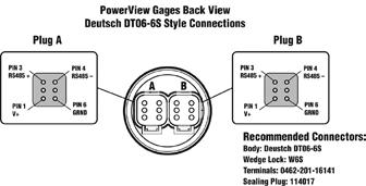
362 Available Bezels Pinout 350
363 How To Order Options listed below. All configurations may not be available. Call your sales representative or Enovation Controls for more information. Shipping Weight: 1 lb. (450 g) All models Shipping Dimensions: 6x6x6 in. (153x153x153mm) All models
364 This Page Has Intentionally Been Left Blank 352
 9 in. (229 mm) 12 in. (305mm) 24 in. (607 mm) 9 in.")
365 353 sect rev. 2014/09/27 Wiring Harness Accessories PowerView PV101 Module and PVA Analog Gages Diagram Use this easy-connect diagram to help you locate the wiring harness you need. How To Order Part Number Length Model: Description Diagram 12 in. (305 mm) 9 in. (229 mm) 12 in. (305mm) 24 in. (607 mm) 9 in. (229 mm) 12 in. (305mm) 24 in. (607 mm) PVW-P-length: CAN and power harness for PowerView module (includes 120Ω CAN resistor) PVW-J-length: PowerView jumper harness PVW-A-length: PowerView audible alarm jumper harness (provides alarm ready contacts for external devices)
 144 in. (3.65 m) 240 in. (6.10 m) 360 in. (9.10 m) 72 in. (1.82 m) 144 in. (3.65 m) 240 in. (6.10 m) 360 in. (9.10 m) 12 in.")
366 How To Order - continued Part Number Length Description Diagram PVJR: Terminating resister (use on last PVA gage in a series - not needed for PV100) in. (1.82 m) 144 in. (3.65 m) 240 in. (6.10 m) 360 in. (9.10 m) 72 in. (1.82 m) 144 in. (3.65 m) 240 in. (6.10 m) 360 in. (9.10 m) 12 in. (305 mm) 24 in. (607 mm) PVW-CH-length: PowerView CAN extension harness PVW-PH-length: PowerView battery Power extension harness PVW-K: PowerView wiring kit includes: one PVW-P, four PVW-J, one PVJR in. (762 mm) PVW-PW-length: PowerView CAN and power loose wiring (includes 120Ω CAN resistor) in. (607 mm) PVW-CC-length: PowerView CAN loose wiring in. (607 mm) PVW-PC-length: PowerView power loose wiring PVW-CT: CAN BUS tee wiring harness 354

367 PowerView Gages PVM Series The PowerView PVM Series Gages are intelligent gages designed to display easy-to-read information transmitted by PowerView. The PVM gages communicate with PowerView via a single RS485 twisted pair MODBUS RTU serial link. The gages can be daisy-chained using quick-connect harnesses. The major feature of the PVM gage is its balance between design and functionality. These modern gages offer a selection of lens and bezel styles and colors. The PVM gages also include features such as a smooth stepper motor operation for the 270 sweep pointer, an environmentally sealed case with two Amp Mini Universal Mate-N-Lok connectors molded into the casing, and green LED backlighting. They are available for standard 2-1/6 (52mm) and 3-3/8 (86mm) diameter hole sizes. Their plastic cases incorporate a D shape allowing panel cutouts that eliminate gage rotation during installation. Features For modern electronic engines and equipment using SAE J1939 Controller Area Network Display SAE J1939 parameters broadcast by the PowerView system Cutting-edge, stepper motor technology and robust functionality combined Microprocessor-driven for high accuracy Simple installation and wiring design Specifications PV101 Compatibility Maximum supported: 5 PVM gages Maximum distance to last gage: 8.5 meters Power Supply Input Voltage: 5V (4.5-5, 5.5 VDC minimum & maximum voltage) Power Supply Operating Current (@ 5 VDC): PVM20, PVM35: 18 ma minimum; 80 ma maximum Backlight Maximum Current: 60 ma Input: RS485 MODBUS RTU data Output: Analog readout Environmental Operating Temperature: -40 to 185 F (-40 to 85 C) Storage Temperature: -67 to 185 F (-55 to 85 C) Environmental Sealed Enclosure: Sealing: IP68, ±5PSI (±34.4 kpa) Case and Clamp Material: Polyester (PBT) Lens Material: Polycarbonate Bezel Material: Polyester (PBT) PVM20 Series 355 sect rev. 2015/09/01 PVM20-A - Engine Oil Pressure PVM20-B - Coolant Temperature PVM20-C - Voltmeter PVM20-D - Percent Load at current RPM PVM20-E - Transmission Oil Pressure PVM20-F - Transmission Oil Temperature PVM20-G - Engine Oil Temperature PVM20-H - Hydraulic Oil Temperature PVM20-J - Percent Fuel Level PVM20-K - Boost Pressure PVM20-L - Exhaust Gas Temperature PVM20-M - Intake Manifold Temperature PVM20-N - Auxiliary Temperature PVM20-P - Auxiliary Pressure PVM20-T - Tachometer PVM35 Series PVM35-T - Tachometer PVM35-S - Speedometer Dial: White numerals over black background Return-to-Zero Needle Movement: Not available for PVM20 models Indicating Pointer: Stepper motor operation with 270 sweep Gage Accuracy: Better than ±1.0% of scale Maximum Panel Thickness: 3/8 in. (9.6 mm) Connectors: Amp Mini Universal Mate-N-Lok Amp Plug P/N: Amp Socket P/N: Shipping Weight: 1 lb. (450 g) Shipping Dimensions: 6 x 6 x 6 in. (153 x 153 x 153 mm)

368 Typical Gage Dimensions PVM20 Series PVM35 Series Bezel Styles 356
369 How to Order Options listed below. All configurations may not be available. Call your sales representative or Enovation Controls for more information. Wiring Harnesses and Accessories For details see bulletin Wiring Harness Accessories for PVM Gages
370 This Page Has Intentionally Been Left Blank 358

371 Wiring Harness Accessories PowerView PV101 and PVM Gages Diagram Use this easy-connect diagram to help you locate the wiring harness you need. NOTE: The PV101 can support up yo five PVM gages in a distance less than 8.5 meters. How to Order Part Number Length Model: Description Diagram in. (305 mm) 9 in. (229 mm) 12 in. (305mm) 24 in. (607 mm) 9 in. (229 mm) 12 in. (305mm) 24 in. (607 mm) PVW-P-length: CAN and power harness for PowerView module (includes 120Ω CAN resistor) PVWM-J-length: Gage harness PVWM-JM-length: PowerView jumper harness 359 sect rev. 2014/09/
 72 in. (1.82 m) 144 in. (3.65 m) 240 in. (6.10 m) 360 in. (9.")
372 How to Order - continued Part Number Length Model: Description Diagram 72 in. (1.82 m) 144 in. (3.65 m) 240 in. (6.10 m) 360 in. (9.10 m) 72 in. (1.82 m) 144 in. (3.65 m) 240 in. (6.10 m) 360 in. (9.10 m) PVW-CH-length: PowerView CAN extension harness PVW-PH-length: PowerView battery power extension harness PVMJR: Terminating Resistor (use on last PVM gage in a series - not needed for PV101) in. (305 mm) in. (607 mm) PVWM-K-length: PV101 - PVM Wiring Kit includes: one PVW-P, four PVWN-J, one PVWM-JM, one PVMJR in. (762 mm) PVW-PW-length: PowerView CAN & Power Loose Wiring (includes 120Ω CAN resistor) in. (607 mm) PVW-CC-length: PowerView CAN Loose Wiring in. (607 mm) PVW-PC-length: PowerView Power Loose Wiring PVW-CT: CAN bus tee Wiring Harness 360

373 PVS-5 Power Supply External power is required to make the PVM gage line compatible with existing MurphyLink products, such as PV1000, Cascade, iguard and eguard. The PVS-5 power supply device supplies 5 volts of external power and load dump protection for up to 6 PVM gages. The maximum length of the power and data connection between gages is 0.5 meters (8.5 meters total). The unit may be installed inside a panel or behind a dash. Specifications Input Voltage: 6 VDC minimum to 32 VDC maximum 12/24 VDC nominal Output Voltage: ma maximum Reverse Polarity Protection: -36 VDC and above Overcurrent Protection: VDA maximum Connector: AMP Operating Temperature: -40 to 185 F (-40 to 85 C) Storage Temperature: -40 to 221 F (-40 to 105 C) Random Vibration: Hz Operating Shock: 50G Certification: CE Case Material: Polyamide Dimensions: 2 x 2 x.75 Mounting Hole Dimensions: Two #8 screws, offset Wiring Diagram 361 Dimensions in. (41.28 mm) in. (41.28 mm) sect rev. 2014/09/ in. (55.83 mm).038 in. (1 mm).25 in in. (47.5 mm).694 in. (.694 mm) (17.63 mm) Mating Connector - Tyco Electronics AMP Mini Universal Mate-N-Lok Plug Housing 4 Position, AMP P/N Murphy P/N
374 How To Order Part Number Description Notes PVS-5 Power Supply Murphy Mating Connector Accessory inch Harness inch Harness PVM Gage Harnesses inch Harness 362
375 Section 80 CAN I/O Modules CAN/IO Modules SenderCAN SAE J1939 Input/Output Module MeCAN Mechanical Engine to J1939 CAN Interface FuelCAN Fuel Level Sender to J1939 Transmitter PowerCore Intelligent Xpansion IX3212 Power Distribution Module (PDM) XM500 I/O Module CANdrive CAN bus J1939 to Electric Gage Interface
376 This Page Has Intentionally Been Left Blank 364

377 SenderCAN SAE J1939 Input and Output Module The SenderCAN is a compact, encapsulated input and output module for J1939 CAN bus systems. SenderCAN allows the integration of analog and digital measurement, control and indicating devices into modern CAN and ECU-based engines and systems. SenderCAN has up to four inputs and two outputs, each of which is factory configured to OEM requirements. Inputs can be set for use with resistive sender or switch signals, which are translated into J1939 CAN bus messages with appropriate PGN address, data scaling and transmission rate. Outputs can be configured to drive gages, lamps, relays or other control devices based on received J1939 data. Standard versions are available for use with common senders (for example, the FuelCAN and MeCAN), but SenderCAN is primarily intended for OEM-specified input, output and CAN bus requirements. Please note that minimum order quantities or charges apply for custom solutions. SenderCAN is compact and light enough for inclusion in most wiring harnesses but can also be surface mounted. The case is fully sealed in epoxy resin for high impact and environmental resistance. Specifications Power supply Operating voltage: 7 to 35 VDC Current consumption: 25mA (typ.) Input/Output Input range: OEM/application specific, -2 to +35 VDC max Output: OEM/application specific, 250mA max. CANbus: SAE J1939 protocol, optional 120 Ohm terminating resistor Physical Case material: High impact ABS, epoxy filled Weight: Approx 60 g / 0.13 lb Operating temperature: -40 o F to +185 o F / (-40 o C to +85 o C) Environmental Sealing: IP65 case, exposed lead ends Electromagnetic compatibility: 2004/108/EC Electrical: J pulses 1c, 2a, 3a/b and 5a EN ESD EN Radiated disturbance EN Fast transients EN High Energy transients EN Conducted RF disturbance CISPR , 4.3 Conducted emissions CISPR Radiated emissions How To Order Please contact your Murphy representative to discuss requirements. Also see FuelCAN and MeCAN variants literature. 365 sect rev. 2015/09/10 Dimensions* and Connections 0.73in. (18.5mm) negative/common - black* input 1 - violet input 2 - orange input 3 - white input 4 - gray output 1 - blue output 2 - brown x 0.234in. (4 x 6mm) 4 places 3.78in. (96.1mm) 1.07in. (27.3mm) 4.21in. (107mm) battery negative - black battery positive - red CAN high - yellow CAN low - green 0.70in. (18mm) * Wire lead not available for all configurations. Standard lead length 4in. (100mm) approx. *Dimensions to be used for reference only. Use actual product for template
378 This Page Has Intentionally Been Left Blank 366

379 MeCAN Mechanical Engine to J1939 CAN Interface The MeCAN is a compact, encapsulated interface module that translates resistive sender, fault switch and speed signals into SAE J1939 CAN bus data. MeCAN allows quick and simple integration of mechanical engines into modern CAN bus systems. Applications include the retrofit of older engine fleets with modern digital instruments, controls and telemetry, engine hour tracking and the development of standard control panels for mechanical engines. MeCAN has three sensor inputs and one output. Two inputs are for oil pressure and coolant temperature sensing, either by fault switches or resistive senders. The third input measures engine speed using a magnetic pickup or charge alternator signal. Input signals are translated into SAE J1939 CAN bus messages with assigned PGN address, data scaling and transmission rate. The output can drive an alarm lamp or buzzer or actuate a shut-down relay if the pressure, temperature or speed inputs deviate outside preset fault limits. A fourth input is connected to a speed calibration potentiometer during set-up mode only. DIP switches allow selection of normal/set up mode and two speed input ranges. An LED gives indication of operating mode and CAN bus activity. MeCAN is compact and light enough for inclusion in engine wiring harnesses but can also be surface mounted. The case is fully sealed in epoxy resin for high impact and environmental resistance. Two standard versions allow use with either fault switches or Murphy ES series resistive senders. Custom solutions are also available for non-standard, volume OEM requirements. Messages Broadcast PGN Description Engine RPM Oil Pressure Coolant Temperature Battery Voltage Engine Hours 367 sect rev. 2015/09/10 Dimensions* and Connections 0.73in. (18.5mm) pickup negative - yellow+green pickup positive - violet oil pressure input - orange coolant temp input - white speed calib. 5K pot - gray shutdown output - blue x 0.234in. (4 x 6mm) 4 places 3.78in. (96.1mm) 1.07in. (27.3mm) 4.21in. (107mm) battery negative - black battery positive - red CAN high - yellow CAN low - green 0.70in. (18mm) Standard lead length 4in. (100mm) approx. *Dimensions are to be used only for reference purposes. Use actual product for template
380 Specifications Power supply Operating voltage: 7 to 35 VDC Current consumption: 25 ma (typ.) Inputs Maximum operating range: -2 to +35 VDC max. Oil pressure, coolant temperature (model MEC301-1): for Murphy ES(2)P and ES(2)T series resistive senders Oil pressure, coolant temperature (model MEC301-2): for fault switch, closing to negative DC on fault Speed (magnetic pickup): Opto-isolated, 3 30 Vrms, adjustable pulses per rev Speed calibration: 0 5 kohm potentiometer (setup only) Outputs (all ratings non-reactive) Shutdown: Negative low-side or ground switch, 250 ma max. CAN bus: SAE J1939 protocol with120 Ohm terminating resistor Physical Case material: High impact ABS, epoxy filled Weight: Approx 60 g / 0.13 lb Operating temperature: -40 F to 185 F (-40 C to 85 C) Environmental sealing: IP65 case (with DIP switch protective film intact), exposed lead ends Electromagnetic compatibility: 2004/108/EC Electrical: -J pulses 1c, 2a, 3a/b and 5a -EN ESD -EN Radiated disturbance -EN Fast transients -EN High energy transients -EN Conducted RF disturbance -CISPR , 4.3 conducted emissions -CISPR Radiated emissions How To Order Part Number Description Notes E MeCAN, with terminating resistor E MeCAN, with terminating resistor Use with pressure and temperature switches (output closes to ground on fault) E MeCAN, with terminating resistor Use with ES(2)P pressure and ES(2)T temperature senders 368
381 FuelCAN Fuel Level Sender to J1939 Transmitter The FuelCAN is a compact interface that translates fuel level sender signals into SAE J1939 CAN bus messages. The device allows integration of standard senders into modern J1939/CAN bus engine instrument and control systems. FuelCAN modules have three inputs (only one of which is connected at any one time): input 1 is configured for use with Murphy ES series resistive fuel level senders; inputs 2 and 3 can be used with fuel level senders having compatible resistance ranges as shown below. FuelCAN inputs can also be factory configured for use with other types of fuel level or resistive senders. FuelCAN is compact and light enough to be incorporated into most wiring harnesses but can also be surface mounted. The polycarbonate case is fully sealed in epoxy resin for high impact and environmental resistance. A rear facing LED indicates input/can bus status. Fuel level / approx. resistance, Ohms Empty 1/4 1/2 3/4 Full Input (Murphy) Input Input Specifications Power supply Operating voltage: 7 to 35 VDC Current consumption: 25 ma (typ.) Inputs Maximum operating range: -2 to +35 VDC Input 1 sender range, Ohms: 240 (empty) to 33.5 (full) Input 2 sender range, Ohms: 240 (empty) to 30 (full) Input 3 sender range, Ohms: 10 (empty) to 180 (full) Outputs CAN bus: SAE J1939 protocol, PGN (00FEFC 16 ) -2 sec update rate -120 Ohm terminating resistor optionally fitted Source Address: 160 (0xA0) Physical Case material: High impact ABS, epoxy filled Weight: Approx 60 g / 0.13 lb Operating temperature: -40 F to 185 F (-40 C to 85 C) Environmental sealing: IP65 case, exposed lead ends Electromagnetic compatibility: 2004/108/EC 369 sect rev. 2015/09/10 Dimensions* and Connections 0.73in. (18.5mm) sender common - black sender input 1 - violet sender input 2 - orange sender input 3 - white x 0.234in. (4 x 6mm) 4 places 3.78in. (96.1mm) 1.07in. (27.3mm) 4.21in. (107mm) battery negative - black battery positive - red CAN high - yellow CAN low - green 0.70in. (18mm) Standard lead length 4in. (100mm) approx. *Dimensions to be used only for reference. Use actual product for template
382 Specifications - continued Electrical: -J pulses 1c, 2a, 3a/b and 5a -EN ESD -EN Radiated disturbance -EN Fast transients -EN High energy transients -EN Conducted RF disturbance -CISPR , 4.3 Conducted Emissions -CISPR Radiated Emissions How To Order Part Number Description Notes E E FuelCAN FuelCAN, with terminating resistor Please contact your Murphy representative to discuss requirements. Also see SenderCAN and MeCAN variants literature. NOTE: Minimum order quantities apply for custom solutions. 370

383 PowerCore Intelligent Xpansion IX3212 Power Distribution Module (PDM) The Murphy PowerCore Intelligent Xpansion Power Distribution Module (PDM) expands CAN bus control networks by replacing existing relay and fuse boxes with more reliable solid-state switches that can directly drive work lights, wiper motors, cooling fans, directional DC motors and other high current loads. Each of the 12 IX3212 outputs can switch or proportionally control up to 15 A loads in 2.5 A increments and feature built-in over-current detection and shut-down capability. Outputs are paired to run up to six electric motors with H-bridge direction control. Twelve digital inputs monitor switched battery, ground and floating inputs. Additionally, eight analog inputs are available with a 5V sensor supply. Wiring length is reduced and costs are cut by remotely locating the IX module near loads and signals. The I/O is multiplexed using a CAN bus network which allows engineers to greatly simplify harness design for ease of installation and improved reliability. For applications not requiring a CAN bus controller, the inputs can directly trigger the outputs so there is no need for a separate controller. The enclosure is fully sealed and potted to withstand wash down and protect from dust. Model Inputs Outputs Specifications IX Analog 8 Digital 12 Digital 12 PWM 12 H-Bridge 6 Operating Voltage: 8-32V (IX ) for 12V and 24V systems Total Current: 70 A maximum continuous Dimensions: 245 mm (L) x 140 mm (W) x 50 mm (H) Mass: 0.9 kg (2.0 lb) Operating Temperature: -40 F to 185 F (-40 C to 85 C) Storage Temperature: -40 F to 275 F (-40 C to 135 C) Electrical and EMI/EMC: 2004/108/EC and 2006/95/EC directives IEC , -4-6 and -4-8 EN / CISPR 11 EN Shock: 30 G, 3 cycles Vibration: 5-25 g, 50-2,000 Hz, 72 hrs per axis Sealing: IP66 and 67, SAE J (10, C and 100 mm away for 15 min) 371 Features 12 Outputs 20 Inputs Sensor Supply Communications Mating Connectors Certifications sect rev. 2015/08/31 (6) 15 A max per channel, 500 Hz (6) 15 A max, 100 Hz Channel overload set in 2.5 A increments High-side, open-loop PWM and directional DC motor control (H-bridge) modes Off-state leakage current <0.1 ma 12 digital, tri-state, input impedance 7.7 kω 6 analog, 0-5 V, input impedance 100 kω pull-down 2 analog, resistive, input impedance 2.2 kω pull-up 10 bit resolution on all analog inputs 70 ma 1 CAN 2.0B, 250 kbps, J1939 proprietary messaging Deutsch DTHD, DT and DTP Series J1, J2 DTHD06-1-4S J3 DT06-12SA (Gray) J4 DT06-12SB (Black) J5 DT06-12SC (Green) J6 DTP06-2S CE mark
 4 DO8/PWM8 Digital Output 8 / PWM 8 (15 A, 100 Hz) 5 DO9/PWM9 Digital Output 9 / PWM 9 (15 A, 100 Hz) 6 DO10/PWM10 Digital Output 10 / PWM 10 (15 A,")
384 Connectors Connector J1 Pin Name Function 1 GND Ground (-) Connector J2 Pin Name Function 1 PWR Power (+) Connector J3 Pin Name Function 1 5V_GND 5V Sensor Ground (-) 2 DI12 Digital Input 12 3 DO7/PWM7 Digital Output 7 / PWM 7 (15 A, 100 Hz) 4 DO8/PWM8 Digital Output 8 / PWM 8 (15 A, 100 Hz) 5 DO9/PWM9 Digital Output 9 / PWM 9 (15 A, 100 Hz) 6 DO10/PWM10 Digital Output 10 / PWM 10 (15 A, 100 Hz) 7 AI8 Analog Input 8 (0-5V) 8 AI7 Analog Input 7 (0-5 ) 9 AI6 Analog Input 6 (0-5V) 10 AI5 Analog Input 5 (0-5 ) 11 AI4 Analog Input 4 (0-5V) 12 5V_PWR 5V Sensor Power (+) Connector J6 Pin Name Function 1 DO12/PWM12 Digital Output 12 / PWM 12 (15 A, 100 Hz) 2 DO11/PWM11 Digital Output 11 / PWM 11 (15 A, 100 Hz) Dimensions Connector J4 Pin Name Function 1 DO1/PWM1 Digital Output 1 / PWM 1 (15A, 500 Hz) 2 DO2/PWM2 Digital Output 2 / PWM 2 (15A, 500 Hz) 3 DO3/PWM3 Digital Output 3 / PWM 3 (15A, 500 Hz) 4 DO4/PWM4 Digital Output 4 / PWM 4 (15A, 500 Hz) 5 DO5/PWM5 Digital Output 5 / PWM 5 (15A, 500 Hz) 6 DO6/PWM6 Digital Output 6 / PWM 6 (15A, 500 Hz) 7 AI3 Analog Input 3 (0-5V) 8 AI2 Analog Input 2 (Resistive) 9 AI1 Analog Input 1 (Resistive) 10 DI11 Digital Input DI2 Digital Input 2 (Source Address 1) 12 DI1 Digital Input 1 (Source Address 0) Connector J5 Pin Name Function 1 CANLO CAN (Green) 2 DI3 Digital Input 3 3 DI4 Digital Input 4 4 DI5 Digital Input 5 5 DI6 Digital Input 6 6 5V_GND 5V Sensor Power (-) 7 5V_PWR 5V Sensor Power (+) 8 DI7 Digital Input 7 9 DI8 Digital Input 8 10 DI9 Digital Input 9 11 DI10 Digital Input CANHI CAN + (Yellow) How To Order Part Number Description Notes E IX , Power Distribution Module 12V or 24V Systems Deutsch DTHD, DTP and DT Connector Kit Plugs, Sockets and Keys 372


385 XM500 I/O Module The XM500 Module is a configurable Input/Output (I/O) module designed to bring analog and digital inputs and output onto the SAE J1939 CAN. The XM500 configuration tool provides a user-friendly interface allowing the user to create or change the configuration used on the XM500 module. Your application may require monitoring of other information which may not be provided by the OEM engine or transmission electronic control unit (ECU), such as fuel level, hydraulic oil pressure or a low engine coolant level switch. The XM500 is ideally suited to bring the additional information you need onto the J1939 CAN bus and can be configured to broadcast fault codes and activate digital outputs per input condition such as fuel level low, hydraulic oil temperature high, etc. Because the XM500 broadcasts information using the J1939 standard protocol, the information can be displayed using standard J1939 display modules, such as the PowerView 101. Diagram 373 sect rev. 2014/09/27 Dimensions and Connections
 Shipping Dimensions: 4 x 6 x 2 Digital Inputs: 4 - Ground or battery positive activation *(Outputs are NOT reverse polarity protected.")
386 Specifications Electrical Digital Outputs*: 2 Sinking (500 ma) Power Input: 8 to 28VDC Product Weight: 10 ounces Communication Ports: CAN J1939 Shipping Weight: 12 ounces Operating Temperature: -40 F to 185 F (-40 C to 85 C) Shipping Dimensions: 4 x 6 x 2 Digital Inputs: 4 - Ground or battery positive activation *(Outputs are NOT reverse polarity protected. Damage will occur if B+ is connected to the outputs. Damage incurred from improper installation is not covered under the Murphy limited warranty policy.) Thermocouple Input 1 : Type K and Type J Analog Inputs 2 : 1 - Battery Supply Voltage (dedicated) 7 - Configurable as 0-5 VDC, 4-20 ma, resistive senders 3 or used as an additional digital input Speed Sensing Input: Magnetic pickup (2 to 120 VAC RMS from 30 to 10,000 Hz) 1 When the thermocouple input is used, only 5 resistive, 4-20 ma, or 0-5 VDC can be used instead of 7. 2 Analog inputs can be exchanged for digital inputs (battery ground activation only) for a total of 11 digital inputs. 3 Other resistive senders can be supported. Contact Murphy s Industrial Panel Division for programming charges. Connector Pins How To Order Connector A (gray) Pin Description 1 Digital IN 2 2 Digital IN 3 3 Analog 6 4 Analog 4 5 Analog 2 6 J & K Type - 7 J & K Type + 8 Analog 1 9 Analog 3 10 Analog 5 11 Analog 7 12 Digital IN 1 Connector B (black) Pin Description 1 Digital OUT CAN high 5 CAN low 6 Battery + 7 Battery Digital IN 4 11 Digital OUT 2 12 MAG pickup Part Number Description Notes XM500 Murphy Standard* Module XM500 Configuration Tool Tool harness with terminating resistor harness without terminating resistor 12 harness with terminating resistor 12 harness without terminating resistor Wire Harness * To determine other configurations, review XM500 Config & Wiring documents at 374


387 CANdrive CAN bus J1939 to Electric Gage Interface As part of the MurphyLink family, CANdrive offers a cost-effective instrument solution for modern electronic engines. CANdrive modules read engine ECU CAN bus/ J1939 data, drive standard electric panel gages and provide LED indication of status and faults. CANdrive has three dedicated outputs for tachometer, oil pressure and coolant temperature gages, with DIP switch selectable compatibility for Murphy, VDO or Datcon gages. For volume orders, the outputs can be custom configured for other gage types, lamps, relays or remote signaling. CANdrive advantages include: the retrofitting of existing electric gage panels to new J1939 compatible engines the use of standard, economical electric gages with new J1939 engines no need for installation of additional gage senders, tachometer magnetic pickups and wiring. CANdrive is packaged in a compact, surface-mounted case with epoxy encapsulation for maximum durability and environmental sealing. Electrical connection is via a 12-way automotive type connector. Model CDV100F has a forward facing connector and one power/ CAN status LED. Model CDV300R has eight LEDs for indication of J1939-transmitted engine faults and status. All models include a six-way DIP switch for flexible configuration. Diagram NOTE: CAN bus J1939 networks typically have two 120 Ohm terminating resistors (one at each end) with a shield/screen connected to ground/earth at one end only. Check engine and ECU documentation for details. Dimensions 375 sect rev. 2014/09/27 Models and Configuration CDV100 Front CDV300 Front Switch Position Options S1 S2 S3 S4 S5 on on on Murphy EG(S) temp. & pressure gages off on on Datcon temp. & 0 7 bar pressure gages off on off Datcon temp. & 0 10 bar pressure gages on off on VDO temp. & 0 5 bar pressure gages on off off VDO temp. & 0 10 bar pressure gages on CAN 120 Ohm terminating resistor in circuit off CAN 120 Ohm terminating resistor removed on 12V DC power supply off 24V DC power supply
388 Specifications Power Supply Operating voltage: 12V range (switch S5 on/up): 7 to 16 VDC 24V range (switch S5 off/down): 19 to 30 VDC Current consumption: CDV100: 25 ma typ. CDV300: 50 ma typ. (2 LEDs lit) Inputs CAN bus: SAE J1939 protocol. Input has a 120 Ohm terminating resistor, removable by switch S4. Outputs (all ratings non-reactive) Oil pressure gage, engine temperature gage: switch selectable for Murphy, VDO or Datcon gages: see Gage Compatibility section for pressure/temperature verses equivalent sender resistance tables Tachometer: pulsed DC, 119 Hz 1500 RPM Physical Electromagnetic compatibility: 2004/108/EC Case material: polycarbonate / polyester / epoxy encapsulation Overall dimensions (w x h x d): 68 x 92 x 22mm / 2.7 x 3.8 x 0.9 in. (allow 50mm / 2.0 in. depth with connector) Weight: approx 80g / 0.2 lb Temperature: Operation: 40 to +85 C / 40 to +185 F, 70% RH Storage: 55 to +105 C / 67 to +221 F Environmental sealing: IP60 (CDV300R: IP65 from front with optional CDVG gasket) Vibration: 15g, 10 to 2000 Hz, 3 axes Shock: 50g, 11 ms, 3 axes Gage Compatibility Pressure Gage Compatibility Table: pressure versus approximate equivalent sender resistance (Ohms) Pressure psi bar Murphy ES series Datcon 0 7 bar Datcon 0 10 bar VDO 0 5 bar VDO 0 10 bar Temperature Gage Compatibility Table: temperature versus approximate equivalent sender resistance (Ohms) Temperature o C o F Murphy ES series Datcon VDO How To Order Part Number Description CDV100F, CANdrive J1939 to gage interface, 1 x CAN status LED, connector forward CDV300R, CANdrive J1939 to gage interface, 8 x status/fault LEDs, connector rearward CDV-PW-30, 8 way wiring harness, length 30 in./760mm CDVG, optional sealing gasket for CDV300R CDV100F plus CDV-PW-30 harness CDV300R, CDV-PW-30 and CDVG gasket CANdrive connector plug shell Connector pins for above (pack of 50) CANdrive installation and operation EG(S)21 series electric gage installation AT series tachometer installation Notes CANdrive CANdrive Accessories Documentation 376
389 Terms and Conditions of Sale Prices: Prices are stated in U.S. Dollars at User Net (List Price) less applicable discount, or Net if so stated. Verbal quotes are subject to confirmation by a written quotation from authorized personnel of Enovation Controls. Verbal quotations expire,unless an order is accepted the same day they are made. Written quotations automatically expire in 30 days unless otherwise stated in writing. They can be terminated by written notice within that period. Price changes apply to all orders received after the effective date and will be billed at the latest price. Blanket orders with scheduled releases will be billed at the new price on the effective date. Taxes: All prices, published or quoted do not include applicable local, state or federal taxes. Applicable taxes must be paid by the Purchaser. Minimum Billing: All orders are subject to a net minimum billing. rev. 2015/10/01 Shortages: Shortages in shipment must be reported within 15 days of material receipt or of invoice date and must be accompanied by the packing list. We reserve the right to back order any item unless you request that shipment be made in full, in which case we will schedule the complete shipment at the earliest date possible. Terms of Payment and Reservation of Title: Terms are net 30 days from date of invoice with approved credit. Enovation Controls reserves the right to require full or partial payment in advance of shipment where the financial condition of the Purchaser does not justify continuance of production or shipment on the terms of payment specified. Orders from Purchasers with unapproved credit ratings may be shipped C.O.D. with reservation of title in Enovation Controls until purchase price shall be paid in full. Export terms will be quoted. All prices are F.O.B. our plant, Tulsa, Oklahoma, or Rosenberg, Texas. Orders: All orders must be bona fide commitments showing stipulated quantities, complete item descriptions and required dates if applicable. We reserve the right to make design changes or improvements without notice. Penalties and Delays: No penalty clause of any kind will be effective unless approved in writing by an authorized officer of Enovation Controls. The company will not be liable for any delay or damage caused by circumstances beyond Enovation Controls reasonable control, including fire, strike, acts of the Purchaser, insurrection, acts of God, transportation failures, or inability to obtain labor, materials or manufacturing facilities. Acceptance: No order is binding upon the company until accepted by an authorized official of Enovation Controls. Cancellation and Alterations: Any order or contract may be canceled or altered by the Purchaser only upon payment of reasonable charges based upon expenses already incurred and commitments made by Enovation Controls for the benefit of the Purchaser. Damage and Loss: Murphy products are packed in specially designed cartons to protect them from shipping damage. Responsibility for delivery lies in the carrier upon our delivery to him and upon his acceptance of the merchandise. All shipments should be inspected upon receipt at destination for damage, either visible or concealed. Claims for loss or damage should be filed with the carrier immediately. Enovation Controls will assist in so far as is practical in securing satisfactory adjustment of claims. However, all claims for loss and damage must be made by the Purchaser to the carrier. Return of Equipment: Material may be returned for credit only upon prior approval of authorized Enovation Controls representative. Accepted items require a Return Authorization Number, must be returned all charges paid and be sufficiently packed to prevent damage during shipment. Items must be new and unused and must have been purchased in the past six months. You must cite your purchase order number and our invoice or order number. Items must be returned through the same channels as purchased. A 15 percent minimum re-stocking charge will be made against all returns of Standard (Make-to-Stock) items. A higher re-stocking charge will apply to all Non-Standard (Assemble-to-Order) items. Custom (Make-to-Order) or special purchase items are not returnable. Credit will apply to future purchases and is not refundable. Repairs: Repair services are available for selected products. Customers will be advised of applicable evaluation fees and estimated repair charges prior to the return. Items returned for repair require a Return Authorization Number and must be returned all charges paid. Warranty: All Enovation Controls manufactured products are warranted against defects in materials and workmanship. The Warranty statement is available upon request or is available on our Website at Repairs beyond the new product warranty carry a 90-day repair warranty. Possession of a Murphy catalog and/or price list does not imply the right to purchase as an authorized Murphy dealer. 377
390 Enovation Controls Limited Warranty rev. 2015/10/01 Enovation Controls supplied products are warranted to be of good quality materials and workmanship. As with any monitoring or control system, the purchase, installation and use of Murphy control instruments and other Murphy systems is NOT AN INSURANCE POLICY. You have purchased dependable instrumentation and with normal care, it will provide long and faithful service and enhance the preventive maintenance program on your valuable equipment. Limited Warranty: Enovation Controls Manufactured Products. Enovation Controls warrants all Enovation Controls manufactured products that it determines to be defective in materials and/or workmanship, under normal use, for a period of TWO years, unless otherwise stated. Non-Enovation Controls Manufactured Products. When Enovation Controls supplies product(s) manufactured by others, the warranty extended to Enovation Controls will be passed through to Enovation Controls customer. During the warranty period, at its sole option, Enovation Controls will use reasonable efforts to repair or replace any defective product; provided, however, that the customer has returned the defective product to Enovation Controls, shipping costs prepaid. Any repair or replacement, at Enovation Controls option, shall be the customer s sole and exclusive remedy. We are not responsible for damage caused by improper installation, neglect or abuse and are limited under warranty to repairing or replacing the item only. We are not liable for equipment on which this product is installed. Warranty Disclaimer ENOVATION CONTROLS SHALL HAVE NO LIABILITY FOR, AND EXPRESSLY DISCLAIMS ANY WARRANTY OR AFFIRMATION OF FACT, EXPRESS OR IMPLIED, OTHER THAN AS SET FORTH IN THIS WARRANTY STATEMENT, INCLUDING, WITHOUT LIMITATION (1) THE IMPLIED WARRANTIES OF MERCHANTABILITY AND FITNESS FOR A PARTICULAR PURPOSE; (2) ANY WARRANTY OR AFFIRMATION OF FACT RELATED TO MISUSE, IMPROPER SELECTION, RECOMMENDATION, OR MISAPPLICATION OF ANY PRODUCT; AND (3) ANY WARRANTY OR AFFIRMATION OF FACT THAT THE CATALOGS, LITERATURE AND WEBSITES IT PROVIDES ACCURATELY ILLUSTRATE AND DESCRIBE PRODUCTS. Product Return Before returning any product customer believes is defective, customer must provide to Enovation Controls details of the warranty claim situation, a complete description of the product, details from the Model Number label attached to each product, including Model Number, part number and date code and obtain from Enovation Controls a Warranty/Return Authorization Number (W&R Number). Any claim for shortage or damage to shipment must be accompanied by the packing slip within 15 days of receipt or invoice date, whichever is later. Damages in shipment are the responsibility of the carrier, and customer must make claim directly with the carrier. Limitation of Liability ANY LIABILITY FOR CONSEQUENTIAL, INCIDENTAL, SPECIAL EXEMPLARY OR PUNITIVE DAMAGES IS EXPRESSLY DISCLAIMED. ENOVATION CONTROLS LIABILITY IN ALL EVENTS SHALL NOT EXCEED THE PURCHASE PRICE PAID FOR THE PRODUCT THAT GIVES RISE TO ANY LIABILITY. ENOVATION CONTROLS REPAIR, REPLACEMENT OR PAYMENT OF SUCH AMOUNT SHALL BE THE FINAL AND EXCLUSIVE REMEDY IN THE EXHAUSTION OR UNAVAILABILITY OF ANY OTHER REMEDY SPECIFIED HEREIN AND SHALL NOT BE CONSTRUED OR ALLEGED BY CUSTOMER TO HAVE FAILED OF ITS ESSENTIAL PURPOSE. THE LIABILITY OF THE COMPANY SHALL CEASE WITH THE EXPIRATION OF THE WARRANTY PERIOD MENTIONED ABOVE. Murphymatic Control Systems If a customer is requesting on-site warranty review or service assistance for a Murphymatic control system, we will engage the proper resources to evaluate the request and to repair, adjust or replace the Murphymatic control system or component(s), in accordance with our Service Philosophy and Limited Warranty. 378
391 Warranty Important Notice Regarding Product Repairs and Warranty Claims In order to provide you with the best service possible and to expedite all product repairs and warranty claims, certain actions and information are required on your part. Partial details follow. For complete details please contact your product Inside Sales Representative. WR Number: A Warranty/Repair Return Authorization Number (WR#) will be required prior to all product returns. This number will allow both of us to track the product and to expedite processing of your request. Simply contact our Inside Sales team to request this number. They will ask certain questions that will identify your exact request so that we can fully comply. They will also advise you of certain procedural changes or conditions that may apply to your request, as outlined below. Complaint/Request Details: Warranty claims require a detailed explanation of the problem or complaint so that we can directly address your concerns. A large percentage of times we are unable to find a problem with the product because we don t know the details of your complaint, and we thus don t know what to look for. We evaluate the product against our specifications, but that may not address your complaint. This explanation will be required for Warranty requests in order to receive the return authorization (WR#). This explanation is also recommended for repairs but is not required. See below for Repairs. Evaluation Fee: An Evaluation Fee covers certain costs associated with diagnosing product problems (or suspected problems). When you request the WR#, your product Sales Representative will advise you of this charge and when it applies. For example, if our evaluation does not support a Warranty Claim, the customer will be asked to pay the fee. However, the fee can be applied to the cost of repair or against the purchase of a new unit. Likewise, the fee can be applied to the cost associated with a nonwarranty repair. If our evaluation supports the Warranty Claim, the fee will be waived. Also see Repairs below. rev. 2015/10/01 Warranty Claim: Contact Enovation Controls to receive WR# Provide detailed explanation of the problem and why Warranty is claimed. Immediate replacement prior to our evaluation will require that the customer purchase a new unit. If the warranty claim is validated, a credit will be issued against the new unit purchased. A customer purchase order is required prior to replacement. Evaluation fee may apply. If applicable, the fee may be applied to repairing the unit or to the purchase of a new unit. Repairs (Non-Warranty): Contact Enovation Controls to receive WR# Some products may no longer be accepted for repair or because of its design cannot be repaired. Others are uneconomical to repair. In some cases, repair parts are available for the customer to make the repair. Your product Sales Representative will advise details when the WR# is requested. (Preferred but not required) Provide detailed explanation of the problem. An estimated repair charge is available for those products that can be repaired. When an exact cost is required prior to the actual repair, an evaluation fee will apply. The fee may be applied toward the final repair cost. A purchase order is required for either the estimated repair charge or the evaluation fee. If the actual cost to repair is greater than 65 percent of the customer s cost to purchase a new product, we will advise. The customer may then proceed with the repair, purchase a new product, scrap the unit or have it returned as is (at customer s expense). If the unit is scrapped or returned, an evaluation fee will apply. NOTE: The evaluation fee is $45 net (no discount). 379
392 Index Symbols 5T, 15T, 12T and 24T and 25 Series Pressure Swichgage 9 20 and 25 Series Temperature Swichgage and 25 Series Vacuum Swichgage 3 20DP, 25DP, A20DP and A25DP Series Pressure Swichgage 5 45APE Series Series CD Ignition A A20 and A25 Series Pressure Swichgage 13 A20 and A25 Series Temperature Swichgage 39 A20 and A25 Series Vacuum Swichgage 3 AEC AFR-1R 227 AFR-9R 229 AFR-64L 233 AFR-64R 231 Air/Fuel Ratio Controls AFR-1R 227 AFR-9R 229 AFR-64L 233 AFR-64R 231 Engine Integrated Control System 235 Air Temperature Sensor 71 Annunciator S Annunciators EN204 Series 305 LCDT 251 Tattletale Annunicators and Magnetic Switches 139 Tattletale Remote Alarm Annunciators 133 TTD 253 AT AT and ATH Series 307 Automatic Engine Controller 199 Auto Start Controllers AEC Cascade 197 B Battery Chargers Sentinel 150 Series 321 Sentinel 300P Series 325 Bilge Level Switch BLSK1 75 BLSK1 Series 75 Brushless Alternators 225 B-Series Murphygage Instrument 17 C CANdrive 375 CANstart 195, 315 CAN I/O Modules CANdrive 375 FuelCAN 369 IX MeCAN 367 SenderCAN 365 XM Cascade 197, 317 Centurion 259 Centurion Configurable Control Panel 269 Centurion PLUS 263 Centurion PLUS Configurable Control Panel 273 CKV series 281 Clutch Controller CO3 247 Clutch Operator 247 CO3 247 Compressor Panels Centurion Configurable Control Panel 269 Centurion PLUS Configurable Control Panel 273 Control Systems & Services 277 TTD Annunciator Panel 267 Controllers Centurion 259 Centurion PLUS 263 Control Systems & Services 277 CS&S 277 D Detonation Sensing Interface System 221 DF Series 77 Dial Level Swichgage 105 Dial Temperature Swichgage 55 Diesel Fuel Check Valves 281 Diesel Fuel Shutoff Valve 283 Differential Pressure Gage for Filter Restriction 5 Digital Engine Controllers EMS Pro 209 EMS Pro Lite 211 Direct Mount Pressure Switch 21 Direct Mount Temperature Swichgage SDB Series 53 Direct Mount Temperature Switch 47 DSI 221 Dual Temperature Swichgage 59 Dump Valves 103 DVU Series 103
393 E EG Series 295 EICS See Engine Integrated Control System Electric Gage Fuel Senders 303 Electric Gages AT and ATH Series 307 EG Series 295 EN Electric Gage Temperature Senders 299 Electric Motor Controllers TR Series 213 Electromechanical Fuel Shutoff Valves 285 Electronic Speed Switches 117 EMS Pro 209 EMS Pro Lite 211 EN204 Series 305 Engine and Generator Controls CANstart 195, 315 Keystart 193, 313 Engine Integrated Control System 235 Engine Monitoring System Controller 209, 211 ML1000-4X Panel 183, 203 ML2000 Panel 185, 207 MPC , 201, 203 MPC , 205, 207 Engine Throttle Controller AT Exhaust Pyrometers 51 F Flasher Alarm 147 FuelCAN 369 G Generator Control Panels MGC MGC MGC Genset Controls CANstart 315 Cascade 317 MGC MGC MGC H Harnesses 187 HD HelmView Displays HVS Hourmeters AT and ATH Series 307 MTH6 113 SHD30 and SHD30-45 Models 115 TM Series 121 HVS Hydrostatic Head Level Switches DF Series 77 I Ignition Coils 223 Ignition Controls 601 Series CD Ignition 219 Brushless Alternators 225 DSI 221 Ignition Coils 223 IntelliSpark 217 Industrial Harnesses 187 Intelligent Xpansion 371 IntelliSpark 217 IX K Keystart 193, 313 L L129 Series 93 L150 and EL150K1 Series 81 L971 Series 95 LCDT 251 Level Maintainers LM LM500/LM500-TF 83 LR LR Level Switches Crankcase L971 Level Switch 95 Scrubber LS MLS Series 97 Liquid Level Switches 97, 99 LM300 Series 85 LM500/LM500-TF 83 LR LS200 Series 99 Lube Level Maintainer 83 Lube Level Swichgage 93 M M25 & M50 Series 281
394 Magnetic Pickups 309 MP MP MP Magnetic Switches Tattletale Annunciators Magnetic Switches 139 Marine Engine Panels MLP Series 189 MRP Series 189 MDTM89 59 MeCAN 367 MGC MGC MGC Mini-siren 147 ML25 Panels 171 ML50 Panels 173 ML100 Panels 175 ML150 Panels 177 ML300 Panels 179 ML1000-4X Panel 183, 203 ML2000 Panel 185, 207 MLC380 Panel 181 MLP Series Panels 189 MLS Series 97 Model 12 Air Temperature Sensor 71 Models M2582-P and M5180-P 289 MP MP MP MPC , 201, 203 MPC , 205, 207 MRP Series Panels 189 MT MTH6 113 Murphygage B-Series Instruments 17 Murphy Industrial Harnesses 187 MurphyLink Panels ML25 Panels 171 ML50 Panels 173 ML100 Panels 175 ML150 Panels 177 ML300 Panels 179 ML1000-4X Panel 183, 203 ML2000 Panel 185, 207 MLC380 Panel 181 Murphy Industrial Harnesses 187 Murphymatic Electric Motor Controllers See Electric Motor Controllers: TR Series Engine Throttle Controller See Engine Throttle Controller: AT03069 O OPLH/OPLHACS Series 105 OPL Series 23 OS77D 117 P Panels MurphyLink Panels See MurphyLink Panels PD8100 Series 291 PDM 371 Pneumatic Valves for Fuel Gas Shutoff 289 PowerCore MPC , 201, 203 MPC , 205, 207 Intelligent Xpansion 371 Power Supply 225, 361 PowerView Analog Gages 349 PowerView CAN Gages 347 PowerView Displays PV25 171, 173, 1331 PV , 177, 333 PV101-A-HAZ 335 PV101-C-HAZ 335 PV , 337 PV , 181, 339 PV PV PowerView Panels MurphyLink Panels See MurphyLink Panels PowerView PVM Gages 355 Pressure Transmitters PXT-K 33 PSB Pressure Switch 21 PT167EX 31 Pulsation Dampener 291 PV25 171, 173, 331 PV , 177, 333 PV101-A-HAZ 335 PV101-C-HAZ 335 PV , 337 PV , 181, 339 PV PV PVA Analog Gages 177, 349 PVCAN Gages 347 PVM Gages 355 PVS PXT-K Series 33 R Rack Pullers RP RP Series 237 Remote Alarm Annunciators See Annunciators RP RP Series 237 RTD 67 RTDT 67
395 S S SAH 147 SDB Series 53 Selectronic Annunciators See Annunciators SenderCAN 365 Senders Electric Gage Fuel 303 Temperature 299 CAN FuelCAN 369 MeCAN 367 SenderCAN 365 Sensing Bulb 49 Sentinel 150 Series 321 Sentinel 300P Series 325 SHD30 and SHD Shock and Vibration Control Switch 129 Shock and Vibration Switch 125 Siren 147 Smart Coils 223 Speed Switches HD9063, OS77D and SS300 Series 117 SPL and 45TE Series 55 SS SV Series 283 Swichgage Electric Gages EG Series 295 Level Float Actuated Oil Level 91 L129 Lube Level 93 L150 and EL150K1 Series 81 OLPH/OPLHACS Series Tank Level 105 Pressure 20 and 25 Series 9 45APE Series 29 A20 and A25 Series 13 Differential Pressure Gage 5 OPL Series 23 PT167EX Lead Line Pressure 31 Shutdown Panels W0156 and W0169 Series 165 WAI Series 149 WD100 Series 153 WD300 Series 155 WDU Series 157 WHB Series 163 WO168 and WO WO Swichgage (continued) Temperature 20 and 25 Series 43 A20 and A25 Series 39 MDTM89 Dual Temperature Gage 59 SDB Series Direct Mount 53 SPL and 45TE Series 55 TDX6 Temperature Scanner/Pyrometer 63 Vacuum A20 and A25 Series 3 T Tachometers AT and ATH Series 307 MT MTH6 113 SHD30 and SHD30-45 Models 115 TC 67 TDX6 63 TDXM 65 Temperature Scanners/Pyrometers TDX6 63 TDXM 65 Temperature Sensors Model 12 Air Temperature Sensor 71 Thermocouple, RTD and RTD Transmitter With Thermowell TC, RTD and RTDT Series 67 Thermocouple, Stainless Steel Tube Type 69 Thermocouple 67, 69 Throttle Controller 245 Timers Models 5T, 15T, 12T and 24T 123 Time Switches 123 TL7 147 TM Series 121 Transformer Relay Assemblies 213 TR Series 213 TSB Temperature Switch 47 TTD 253 TTD Annunciator Panel 267 V Valves Check/Relief Valves - Diesel Fuel CKV series 281 Level DVU Series 103 Pulsation Dampener PD8100 Series 291 Shutoff Valves M25 & M50 Series, 281 Models M2582-P and M5180-P 289 SV Series 283 Vibration Switches VS2 Series 125 VS94 Model 129 VS2 Series 125
396 VS94 Model 129 W W0156 and W0169 Series 165 WAI Series 149 WD100 Series 153 WD300 Series 155 WDU Series 157 WHB Series 163 Wiring Harness For PV101 and PVA Analog Gages 353 For PV101 and PVM Gages 359 WO WO WO X XM
397
398
399
 CO, LTD.")
400 ENOVATION CONTROLS CORPORATE HEADQUARTERS 5311 S 122ND EAST AVENUE TULSA, OK ENOVATION CONTROLS SAN ANTONIO OFFICE 5757 FARINON DRIVE SAN ANTONIO, TX ENOVATION CONTROLS HOUSTON OFFICE 105 RANDON DYER RD ROSENBERG, TX ENOVATION CONTROLS LTD. UNITED KINGDOM CHURCH ROAD LAVERSTOCK SALISBURY SP1 1QZ UK MURPHY ECONTROLS TECHNOLOGIES (HANGZHOU) CO, LTD RD STREET HANGZHOU ECONOMIC & TECHNOLOGICAL DEVELOPMENT AREA HANGZHOU, ZHEJIANG CHINA DOMESTIC SALES & SUPPORT ECONTROLS PRODUCTS PHONE: FAX: INFO@ENOVATIONCONTROLS.COM MURPHY PRODUCTS PHONE: FAX: SALES@ENOVATIONCONTROLS.COM MURPHY CONTROL SYSTEMS & SERVICES PHONE: FAX: CSS SOLUTIONS@ENOVATIONCONTROLS.COM MURPHY INDUSTRIAL PANEL DIVISION PHONE: FAX: IPDSALES@ENOVATIONCONTROLS.COM INTERNATIONAL SALES & SUPPORT UNITED KINGDOM PHONE: FAX: SALES@ENOVATIONCONTROLS.EU CHINA PHONE: FAX: APSALES@ENOVATIONCONTROLS.COM LATIN AMERICA & CARIBBEAN PHONE: LASALES@ENOVATIONCONTROLS.COM SOUTH KOREA PHONE: SKOREASALES@ENOVATIONCONTROLS.COM INDIA PHONE: INDIASALES@ENOVATIONCONTROLS.COM FM (Tulsa, OK - USA) FM (San Antonio, TX - USA) FM (Rosenberg, TX - USA) FM (UK) FM (China) Distributed by: TS (China) In order to bring you the highest quality, full-featured products, we reserve the right to change our specifications and designs at any time. Specifications and performance data subject to change without notice. Certified specifications and performance data available upon request. All trademarks and service marks used in this document are the property of their respective owners. Printed in the USA
Pressure Gage and Swichgage Instruments OPL Series 4-1/2 in. (114 mm) Diameter Dial
 Diameter Dial") Pressure Gage and Swichgage Instruments OPL Series 4-1/2 in. (114 mm) Diameter Dial 96001 Revised 07-27-10 Section 05 R 1 2 Features Combination Indicating Gage and Critical Pressure Limit Switches High
Pressure Gage and Swichgage Instruments OPL Series 4-1/2 in. (114 mm) Diameter Dial 96001 Revised 07-27-10 Section 05 R 1 2 Features Combination Indicating Gage and Critical Pressure Limit Switches High
POWER CONTROLS. Complete Solutions to Meet Your Needs.
 POWER CONTROLS Complete Solutions to Meet Your Needs. CORPORATE HEADQUARTERS & MANUFACTURING MANUFACTURING SALES/APPLICATIONS 2 WHO WE ARE More than 70 years ago, our products started with a simple idea
Tattletale Annunciators and Magnetic Switches
 Tattletale Annunciators and Magnetic Switches Tattletale annunciators and magnetic switches are the nerve centers that translate Swichgage contact operations into decisions and operate the alarm or shutdown
Installation for L1100, L1200, L1200N Series Liquid Level Switches and DVU150, DVU175, and DVU2105/2115/2120 Series Dump Valves. GENERAL INFORMATION
 Installation for L1100, L1200, Series Liquid Level Switches and DVU150, DVU175, and DVU2105/2115/2120 Series Dump Valves. A =1-1/2 NPT B =2 NPT Meets NACE standard MR-01-75 for direct exposure to H2 S
WARNING. Murphy W-Series Engine Panels General Installation Instructions. Installation Accessories
 Murphy W-Series Engine Panels General Installation Instructions WS-93002N Revised 04-06 Section 30 (00-02-0191) Read the following information before installing. These installation instructions are typical
WARNING. Murphy W-Series Engine Panels General Installation Instructions. Installation Accessories
 Murphy W-Series Engine Panels General Installation Instructions WS-93002N Revised 08-02 Section 30 (00-02-0191) Read the following information before installing. These installation instructions are typical
DF Series Hydrostatic Head Level Switches
 DF Series Hydrostatic Head Level Switches Installation and Operations Manual 00-02-0831 2013-03-21 Section 15 In order to consistently bring you the highest quality, full featured products, we reserve
WARNING. Diode Package The Murphy diode package ( ) is designed to allow the fuel shutoff valve to be used with dual Magneto Ignition systems.
 is designed to allow the fuel shutoff valve to be used with dual Magneto Ignition systems.") M2582, M508, and M580 Series Electromechanical and Pneumatic, Fuel Gas Shutoff Valves Installation and Operation Instructions Please read the following instructions before installing. A visual inspection
M2582, M508, and M580 Series Electromechanical and Pneumatic, Fuel Gas Shutoff Valves Installation and Operation Instructions Please read the following instructions before installing. A visual inspection
P70, P72, and P170 Controls for Low Pressure Applications
 Master Catalog 125 Pressure Controls Section P Product/Technical Bulletin Issue Date 0900 P70, P72, and P170 Controls for Low Pressure Applications The P70, P72, and P170 controls for low pressure applications
FWMURPHY. Industrial Applications. Oil & Gas Applications. Condensed Catalog. Control & Instrumentation. Solutions
 FWMURPHY Industrial Applications Oil & Gas Applications 32 Condensed Catalog Control & Instrumentation Solutions TAKE A CLOSER LOOK AT POWERVIEW NOW YOU KNOW WHAT YOUR ELECTRONIC ENGINE IS TELLING YOU.
Lube Level Maintainer
 Lube Level Maintainer Models LM2000/LM2000S Installation Instructions 00-02-0423 Revised 08-12-09 Section 15 In order to consistently bring you the highest quality, full featured products, we reserve the
DWYER INSTRUMENTS, INC. Phone: 219/ P.O. BOX 373 MICHIGAN CITY, IN 46361, U.S.A. Fax: 219/
 Series 43000 Capsu-Photohelic Pressure Switch/Gage Specifications - Installation and Operating Instructions Bulletin B-34 Ø4-3/4 [120.65] 3-7/8 SQ [98.43] 3/4 CONDUIT 4-3/8 [111.13] HOUSING REMOVAL 3-1/16
LS200, LS200N, LS200NDVOR Series and L1100 Liquid Level Switches
 LS200, LS200N, LS200NDVOR Series and L1100 Liquid Level Switches Installation and Operations Manual CALL MURCAL TO PLACE YOUR ORDER P:(661)272-4700 F:(661)947-7570 www.murcal.com e-mail: sales@murcal.com
PowerView PV380-R2 Mechanical Configuration
 PowerView PV380-R2 Mechanical Configuration Operations Manual *Products covered in this document comply with European Council electromagnetic compatibility directive 2004/108/EC and electrical safety directive
Your Source for Engine and Equipment Management. Oil & Gas
 Your Source for Engine and Equipment Management Oil & Gas Your Source for Engine and Equipment Management For more than 60 years, people all around the world have looked to Murphy for help managing engine
Lube Level Maintainer
 Lube Level Maintainer Models LM500/LM500-TF Installation Instructions 00-02-0729 2015-05-30 Section 15 BEFORE INSTALLING THIS MURPHY PRODUCT: A visual inspection of this product for damage during shipping
PISTON STYLE GAUGE. Mid-West Instrument
 PISTON STYLE GAUGE Mid-West Instrument 1 BULLETIN NO. 120/11 (SUPERSEDES BULLETIN NO. 120/02) Mid-West Instrument Piston Type Differential Pressure Gauges Switches & Transmitters Model 120 A low cost differential
Electric Gage Shutdown Panels for DEUTZ 1011/2011, 912/913 and 914
 Electric Gage Shutdown Panels for DEUTZ 1011/2011, 912/913 and 914 WDU-04001B Effective 02-04 Catalog Section 30 (00-02-0560) WDU0814, WDU0815, WDU0816 Panels Coolant Temperature Voltmeter Oil Pressure
2 1 /2" Glycerin-Filled Dual Scale Vacuum Gauges
 BAC-25 Brass Case Dial Size: 2 1 /2" Glycerin Filled Pressure Ranges: 30" HG to 15,000 PSI/Bar (Dual Scale) Accuracy: Within 1.5% of Maximum Graduation Case: Forged Brass With Polished Brass ABS Bourdon
CAPSU-PHOTOHELIC PRESSURE SWITCH/GAGE*
 CAPSU-PHOTOHELIC PRESSURE SWITCH/GAGE* Specifications - Installation and Operating Instructions Bulletin B-34 Series 43000 CAPSU-Photohelic Switch/Gage The CAPSU-Photohelic Switch/Gage is a most versatile,
WARNING. Diode Package The Murphy diode package ( ) is designed to allow the fuel shutoff valve to be used with dual Magneto Ignition systems.
 is designed to allow the fuel shutoff valve to be used with dual Magneto Ignition systems.") M2582, M508, and M580 Series Electromechanical and Pneumatic, Fuel Gas Shutoff Valves Installation and Operation Instructions Please read the following instructions before installing. A visual inspection
M2582, M508, and M580 Series Electromechanical and Pneumatic, Fuel Gas Shutoff Valves Installation and Operation Instructions Please read the following instructions before installing. A visual inspection
Pressure Instrument Testing Equipment
 Pressure Instrument Testing Equipment BULLETIN TE-1 A Halliburton Company A Durable, Portable Primary Standard Model 1305D Deadweight Tester The Ashcroft 1305D Deadweight Tester is an affordable, portable
Frank W. Murphy Ltd. Control Panel Catalogue
 SS6358 18/07/06 Frank W. Murphy Ltd. Control Panel Catalogue Frank W. Murphy Ltd. Swichgage House Church Road Laverstock Salisbury SP1 1QZ United Kingdom tel: +44 (0)1722 410055 fax: +44 (0)1722 410088
NEMA 4 High Pressure High Set Point High Accuracy Pressure Switch SPECIFICATIONS
 Pressure Switches P605L NEMA 4 High Pressure High Set Point High Accuracy Pressure Switch OVERVIEW The Whitman Controls P605L NEMA 4 High Pressure High Set Point High Accuracy Pressure Switches are a line
Powers TM Controls SW 141 Differential Static Airflow Switches
 Powers TM Controls SW 141 Differential Static Airflow Switches Document No. 155-052P25 SW 1 0518 Description The SW 141 Airflow Switch senses static differential pressure and the diaphragm operated snap
Severe Service 40MM & 50MM SEVERE SERVICE GAUGE
 Severe Service 40MM & 50MM SEVERE SERVICE GAUGE Copper Alloy Internals Glycerine Filled Center Back Mount Only Marsh Instruments Liquid-Filled Gauges are designed to perform in rugged and harsh environmental
PISTON STYLE GAUGE. For Installation and Operation Manuals Please Visit: Mid-West Instrument
 PISTON STYLE GAUGE For Installation and Operation Manuals Please Visit: www.midwestinstrument.com/literature Mid-West Instrument BULLETIN NO. 120/11 (SUPERSEDES BULLETIN NO. 120/02) Mid-West Instrument
NOTICE FOR ALL EG21 ELECTRIC GAGES AND EGS21
 EG21 and EGS21 Series Electric Gage and SWICHGAGE Installation For Pressure,, Fuel Level, Voltmeter and Ammeter Patents 5121109, 4975687 and 5608386 CAUTION IMPORTANT NOTICE FOR ALL EG21 ELECTRIC GAGES
Remote Temperature Controllers. Quick Selection Guide
 Remote Temperature Controllers Quick Selection Guide A Complete Selection For A Wide Range Of Applications Electronic Standalone Controllers T775 Provide on/off, modulating, or reset control in applications
P70, P72, and P170 Series Controls for High Pressure Applications
 Installation Instructions P70 Issue Date 0918 P70, P72, and P170 Series Controls for High Pressure Applications Application P70, P72, and P170 Series Controls for High Pressure Applications provide high-side
Tachometers and Tach/Hourmeters AT and ATH Series
 Tachometers and Tach/Hourmeters AT and ATH Series Installation Instructions 00-02-0986 Section 70 IMPORTANT! These instructions are specific to tachometer models with a single calibration push button.
PXT-K Series. Pressure Transmitters Section 05
 PXT-K Series Pressure Transmitters 00-02-0840 Section 05 This Murphy instrument is susceptible to damage when exposed to static electrical changes. To avoid this damage, observe the following: Disconnect
P70, P72 and P170 Series Controls for High Pressure Applications
 Installation Instructions P70 Issue Date October 16, 2002 P70, P72 and P170 Series Controls for High Pressure Applications Application P70, P72 and P170 Series Controls for High Pressure Applications provide
2011 Special OEM Instrumentation Catalog
 www.vdo.com/usa 2011 Special OEM Instrumentation Catalog Part #VSOC0510 (Supersedes Part #VSOC0908) Instrumentation Sensors A heritage of engineering quality and innovation We re focused on providing our
short form catalog SFC 07
 short form catalog Electronic and Electromechanical Switches for Pressure, Differential Pressure, and Temperature Pressure Transmitters and Transducers Industrial Temperature Sensors SFC 07 is a privately
Precision Service OBSOLETE 100MM STAINLESS STEEL GAUGES. (Subject to available inventory) SPECIFICATIONS DIMENSIONS ACCURACY CASE SIZES CASE MATERIAL
 SPECIFICATIONS DIMENSIONS ACCURACY CASE SIZES CASE MATERIAL") ASME Grade A ±.0% of range 00mm diameter (4") 304 CASE STYLES UC U-Clamp Mount FF Front Flange Mount 36 4" NPT lower or lowerback connection 30 to 0,000 psi Dual scale psi and kpa Aluminum, black painted
ASME Grade A ±.0% of range 00mm diameter (4") 304 CASE STYLES UC U-Clamp Mount FF Front Flange Mount 36 4" NPT lower or lowerback connection 30 to 0,000 psi Dual scale psi and kpa Aluminum, black painted
BULLETIN NO.ELEC IM121/10A Replaces IM121/09A
 Mid-West Instrument BULLETIN NO.ELEC IM121/10A Replaces IM121/09A INSPECTION Model 121 Indicating Differential Pressure Switch / Transmitter Electrical: Installation and Operating Instructions Upon receipt
Cascade CD101 Auto-Start Controller. Installation and Operations Manual Sections 40 & 75
 Cascade CD101 Auto-Start Controller Installation and Operations Manual 00-02-0594 2018-02-15 Sections 40 & 75 In order to consistently bring you the highest quality, full featured products, we reserve
Distributed By: M&M Control Service, Inc PRODUCT PRODUCT CODE TECHNICAL INSTRUCTIONS PAGE #
 PRODUCT PRODUCT CODE TECHNICAL INSTRUCTIONS PAGE # Switches Selector Switches SW 786 155-118P25 G-3 Positioning Switch SW 141 155-117P25 G-5 Enthalpy Control Switch EE 141 155-054P25 G-7 Static Pressure
Mid-West Instrument. Piston Type Model 220. Hazardous Locations. Indicating / Non-Indicating Differential Pressure Switch or Transmitter
 BULLETIN NO. 220/11 (SUPERSEDES BULLETIN NO. 220/06) Mid-West Instrument Piston Type Model 220 Hazardous Locations Indicating / Non-Indicating Differential Pressure Switch or Transmitter Low cost piston
Pressure Controls Product Overview
 Bulletin Product Overview NEMA Bulletin Style A (Internal Bellows) Description Style C (External Bellows) Air Compressors Compressed Air Monitor Systems Liquid Level Control Typical Applications Vacuum
± ± ± ± ± ± ± ± 85.
 Pressure Switches J705 High Pressure High Set Point Pressure Switch OVERVIEW The Whitman Controls J705 High Pressure High Set Point Pressure Switches are among our most durable products, affording the
WGI. General Purpose Pressure Gauges Painted Steel Case Copper Alloy Internals Classic Series Model WJ04/06
 WGI Pressure Gauges General Purpose Pressure Gauges Painted Steel Case Copper Alloy Internals Classic Series Model WJ4/6 1½ Dial Application WGI Classic series pressure gauges are for general service applications
TAKE A CLOSER LOOK AT POWERVIEW. THE LATEST ADDITION TO THE MURPHYLINK TM FAMILY.
 TAKE A CLOSER LOOK AT POWERVIEW. THE LATEST ADDITION TO THE MURPHYLINK TM FAMILY. INTRODUCING THE NEXT GENERATION MURPHYLINK SYSTEM. POWERVIEW INSTRUMENTS AND GAGES ARE THE MOST ADVANCED J1939 CAN SOLUTIONS
Mid-West Instrument. Piston Type Differential Pressure Gauges Switches & Transmitters Model 123
 BULLETIN NO. 123/11 (SUPERSEDES BULLETIN NO. 123/03) Piston Type Differential Pressure Gauges Switches & Transmitters A low cost differential pressure gauge for use in measuring the pressure drop across
MODEL PC-252 Transformer Temperature Indicator Oil & Winding Temperature Indicator (with Micro Switches)
") 1. Description: PC 252 is a Liquid-in-Metal expansion type Self powered Oil/ Winding Temperature Indicator for Power & Distribution transformers. PC 252 is Approved & Used by all reputed customers in India
1. Description: PC 252 is a Liquid-in-Metal expansion type Self powered Oil/ Winding Temperature Indicator for Power & Distribution transformers. PC 252 is Approved & Used by all reputed customers in India
Lube Level Maintainer
 Lube Level Maintainer Model LM500-TF-ATEX Installation Instructions 00-02-0745 2013-09-16 Section 15 Ex ic IIC T5 Gc X -20 o C < Ta < 85 o C NOTE: To use in an ATEX environment the metal vent cap must
Palmer Circular Chart Recorders
 Palmer Circular Chart Recorders Pressure & Temperature Recorders Designed for indoor or outdoor use, our recorders provide long service life, even in harsh conditions. Internal Assemblies, Clocks and Parts
Mid-West Instrument. Diaphragm Type Differential Pressure Gauge & Switch Model 130. Shown here with Range 0-5 H2O
 Diaphragm Type Differential Pressure Gauge & Switch BULLETIN NO. 130/11 (SUPERSEDES BULLETIN NO. 130/02) is a rugged general purpose differential pressure gauge with a 4-1/2" round dial. Common Applications:
Data Sheet. A-Series Miniature Watertight Pressure Switches
 A-Series Miniature Watertight Pressure Switches FEATURES Compact size 36 Stainless steel construction Pressure ranges from vacuum to 000 bar (5.000 psi) Factory set or field adjustable setpoints Wide operating
Lube Level Maintainer
 Lube Level Maintainer Models LM500/LM500-TF Installation Instructions 00-02-0729 02-11-11 Section 15 Please read the following information before installing. BEFORE BEGINNING INSTALLATION OF THIS MURPHY
for ethanol applications
 Biofuels Pressure and Temperature Instrumentation for ethanol applications WIKA Instrument Corporation manufactures products engineered with specific design features and gauge options optimized for utilization
Pneumatic Controls. Pneumatic Controls Sections
 Pneumatic Controls Pneumatic Controls Sections Controllers and Switches Thermostats Relays Sensors and Transmitters See the Contents Section at the front of the Product Catalog for the complete data sheet
Data Sheet. A-Series Miniature Watertight Pressure Switches. Factory set or field adjustable
 FEATURES Compact size 36 stainless steel construction Pressure ranges from vacuum to 5,000 psi Factory set or field adjustable setpoints Wide operating temperature range ( 40 C to 00 C) Precision snap-acting
WARNING. Models Magnetic Sensor Tachometer 3000 RPM; pulses 12 VDC
 Tachometer and Tach/Hourmeter Installation Instructions Series: ATS, ATHS, ATA, ATHA, ATHI Please read the following instructions before installing. A visual inspection is recommended before mounting.
High-impact moisture-resistant polyester (PBT)
") INSTRUMENTS Rugged products for demanding O.E.M. applications DESCRIPTION: Full line of heavy-duty gauges, tachometers & speedometers ideally suited for rugged O.E.M. off-highway, industrial & specialty
INSTRUMENTS Rugged products for demanding O.E.M. applications DESCRIPTION: Full line of heavy-duty gauges, tachometers & speedometers ideally suited for rugged O.E.M. off-highway, industrial & specialty
Mid-West Instrument. Piston Type Differential Pressure Gauges Switches & Transmitters Model 120
 BULLETIN NO. 120/11 (SUPERSEDES BULLETIN NO. 120/02) Piston Type Differential Pressure Gauges Switches & Transmitters A low cost differential pressure gauge for use in measuring the pressure drop across
Mid-West Instrument. Diaphragm Type Model 240. Hazardous Locations. Indicating / Non-Indicating Differential Pressure Switch or Transmitter
 BULLETIN NO. 240/11 (SUPERSEDES BULLETIN NO. 240/06) Mid-West Instrument Diaphragm Type Model 240 Hazardous Locations Indicating / Non-Indicating Differential Pressure Switch or Transmitter Field wireable
Mid-West Instrument. Piston Type Differential Pressure Gauges Switches & Transmitters Model 122
 BULLETIN NO. 122/11 (SUPERSEDES BULLETIN NO. 122/01) Piston Type Differential Pressure Gauges Switches & Transmitters A low cost differential pressure gauge for use in measuring the pressure drop across
VACUUM A RESOURCE FOR EVERYONE
 Vacuum grippers VACUUM PRODUCTS INNOVATORS IN VACUUM TECHNOLOGY CATALOG VERSION 5.0 VACUUM A RESOURCE FOR EVERYONE www.piab.com Accessories Suction cups Vacuum pumps PVA VACUUM SWITCHES, INDUCTIVE UNIVERSAL
Fisher 2506 and 2516 Receiver Controllers
 2506/2516 Receiver Controllers Product Bulletin Fisher 2506 and 2516 Receiver Controllers The 2506 receiver controller takes the input from a pneumatic transmitter, matches it against the adjustable set
UNITED ELECTRIC 100 Series, Pressure, Vacuum, Diff. Pressure & Temp. Switches Adjustable Ranges 30 Vac to 5000 PSI, -180 to 650 o F
 UNITED ELECTRIC 100 Series, Pressure, Vacuum, Diff. Pressure & Temp. Switches Adjustable Ranges 30 Vac to 5000 PSI, -180 to 650 o F DESCRIPTION The 100 Series is a cost-effective pressure and temperature
Pressure Controller. Cataloge K Code Characteristics Index. K00-2 Pressure Controller Brief Introduction
 K Pressure Controller Cataloge Code Characteristics Index K00-2 Pressure Controller Brief Introduction KC32 Screw Tube Differential Pressure Controller K01 KY10 Bellows Type Differential Pressure Controller
Steam & Hot Water INSTRUMENTS. Adjustable Angle Industrial Thermometer. Econo Thermometer. ] Aluminum Stem. ] Air-Duct Stem
![Steam & Hot Water INSTRUMENTS. Adjustable Angle Industrial Thermometer. Econo Thermometer. ] Aluminum Stem. ] Air-Duct Stem](/thumbs/77/76699903.jpg "Steam & Hot Water INSTRUMENTS. Adjustable Angle Industrial Thermometer. Econo Thermometer. ] Aluminum Stem. ] Air-Duct Stem") Adjustable Angle Industrial Thermometer Recognized globally as the Trerice BX Industrial Thermometer, this is an instrument of extreme accuracy and rugged dependability. Available in scale lengths of 7"(AX),
Adjustable Angle Industrial Thermometer Recognized globally as the Trerice BX Industrial Thermometer, this is an instrument of extreme accuracy and rugged dependability. Available in scale lengths of 7"(AX),
Marsh Instruments. STD Pocket Thermometer. Digital Pocket Thermometer. Specifications. Specifications. Gas Pressure Test Set. belgas.
 Marsh Instruments STD Pocket Thermometer 1" Dial 304SS Hermetically Sealed Case 5" long stem Protective Case with SS Clip Digital Pocket Thermometer 3.5 Digital LCD display ABS Plastic Case 5" long stem
Marsh Instruments. Marshalltown Value Series Gauge. Specifications. X-Mas Tree Gauge. Specifications. belgas.net 1
 Marsh Instruments Marshalltown Value Series Gauge ASME Grade B Extra Savings with Quantity Pricing 4 Standard Mounting Options: LM, CB, Right & Left (1.5" Only) Marshalltown Value Series are the most economical,
Temperature Switches
 Temperature Switches Temperature Switches c Pressure - Electronic Pressure Switches - Mechanical Pressure Switches - Pressure Transducer c Valves & Regulators c Temperature c Level c Flow c Air Suspension
Automation Selection Guide
 A Bray High Performance Company A Subsidiary of BRAY INTERNATIONAL, Inc. Automation Selection Guide Automator Products Pneumatic & Electric Actuators And Accessories PDF processed with CutePDF evaluation
Temperature Products. Temperature Products
 Temperature Products Temperature Products u Electronic Products u Pressure Transducers u Mechanical Pressure Products u Valves & Regulators u Temperature Products u Level Products u Air Suspension Valves
Liquid Filled HW 160MM STAINLESS STEEL SPECIFICATIONS. 26 HW 160MM STAINLESS STEEL GAUGES ACCURACY CASE SIZES CASE MATERIAL
 Liquid Filled HW 60MM STAINLESS STEEL Liquid Filled or Dry - Field Fillable Socket Welded to the Case Ranges to 20,000 psi Heavy Duty All Stainless Steel Marsh Instruments HW 60mm Stainless Steel gauges
Double Acting & Spring Return. SERIES 92/93 Rack & Pinion PNEUMATIC ACTUATOR. The High Performance Company
 PNEUMATIC ACTUATOR SERIES 92/93 Rack & Pinion Double Acting & Spring Return The High Performance Company SERIES 92/93 Styling, strength, compactness, and simplicity of design have been combined to produce
TK-6024, TK-6124, TK-8024, TK-8124
 TK-6024, TK-6124, TK-8024, TK-8124 Pneumatic Bulb Thermostats General Instructions APPLICATION For proportional temperature control of pneumatic valves and actuators to maintain air or liquid temperatures
MEASUREMENT SOLUTIONS FOR THE WATER & WASTEWATER INDUSTRY
 MEASUREMENT SOLUTIONS FOR THE WATER & WASTEWATER INDUSTRY MUNICIPAL AND INDUSTRIAL WATER & WASTEWATER PROCESSING NOSHOK provides pressure, level and temperature measurement solutions, along with diaphragm
Reliable liquid or simulated winding indication at eye level
 qualitrol 104/TR6000 Remote mount thermometers Reliable liquid or simulated winding indication at eye level Rugged construction and corrosion resistant materials for life-long function Wide array of options
Mid-West Instrument. Piston Type Differential Pressure Gauges Switches & Transmitters Model 124
 BULLETIN NO. 124/12 (SUPERSEDES BULLETIN NO. 124/11) Mid-West Instrument Piston Type Differential Pressure Gauges Switches & Transmitters A low cost differential pressure gauge for use in measuring the
SPECIALISTS IN PRESSURE, TEMPERATURE, LEVEL, FLOW, GAS DETECTION, CALIBARATION & FLUID POWER INSTRUMENTATION
 SPECIALISTS IN PRESSURE, TEMPERATURE, LEVEL, FLOW, GAS DETECTION, CALIBARATION & FLUID POWER INSTRUMENTATION EMAIL: SALES@GMINSTRUMENTATION.CO.UK WEBSITE: WWW.GMINSTRUMENTATION.CO.UK THERMOCOUPLES & PLATINUM
Switches for Pressure to 8000 psig, Vacuum, Differential, or Level Control with General Purpose, Watertight or Explosion-Proof Enclosures
 S-SERIES Pressure Switches Switches for Pressure to 8000 psig, Vacuum, Differential, or Level Control with, or s Features: Set point repeatability, +1% of operating range. All wiring terminals, adjustments
Bourdon Tube Pressure Switches
 DA /DS Bourdon Tube es Visible setpoint, adjustable deadband, snap action switch pressure ranges to 000 psi Weather-Proof Types DAW, DSW, DRW -/1 2-1/1 REAR MOUNTING FLANGE ().20 DIA. HOLES AT 120 ON -1/2
for biodiesel applications
 Biofuels Pressure and Temperature Instrumentation for biodiesel applications WIKA Instrument Corporation manufactures products engineered with specific design features and gauge options optimized for utilization
Model 124 Filter Minder & Model 124
 Installation & Maintenance Instructions Model 124 Filter Minder & Model 124 Indicating Differential Pressure Switch / Transmitter Reading Office Cutbush Park, Danehill, Lower Earley, Reading, Berkshire.
System 350 P352AB Electronic Pressure Control Series
 System 350 P352AB Electronic Pressure Control Series System 350 Product Guide 930 Basic Controls Section Product/Technical Bulletin P352AB Issue Date 0200 The P352AB controls are On/Off electronic pressure
Powers TM Controls SW 134 Pressure Electric Switch (Adjustable Differential)
") Powers TM Controls SW 134 Pressure Electric Switch (Adjustable Differential) Document No. 155-050P25 SW 134-3 Description The SW 134 Pressure Electric Switch actuates electrical circuits from pneumatic
Powers TM Controls SW 134 Pressure Electric Switch (Adjustable Differential) Document No. 155-050P25 SW 134-3 Description The SW 134 Pressure Electric Switch actuates electrical circuits from pneumatic
Product Catalog. Our Products. DCI Dynamic Instruments Website: dcidynamic.com
 1 Product Catalog Our Products We at Dynamic are proud to present out new technical catalogue detailing our extensive range of Pressure Gauges, Thermometers, diaphragm seal, transmitter and accessories.
E. Clark & Associates 10 Brent Drive Hudson, MA Tel. 978 / Fax 978 / Two Switch Output Hex Screw Adjustment
 CLARK SOLUTIONS 400 Series, Pressure, Vacuum, Diff. Pressure & Temp. Switches 1,2 & 3 Switch output, Adjustable Ranges 30 Vac to 6000 PSI, -180 to 650 o F DESCRIPTION The 400 Series is a versatile family
Shuttle Type Switches For Moderate to High Liquid Flow Rates
 Shuttle Type Switches For Moderate to High Liquid Flow Rates Models for flow rate settings from.5 GPM to 100.0 GPM Rugged housings with port sizes ranging from 3/4 to 3 Efficient flow paths assure low
MurphyLink Series M310 Panels
 MurphyLink Series M310 Panels 03022 Revised 07-28-10 Section 30 Features Standard panel designed for modern electronic engines and equipment applications using SAE J1939 Controller Area Network (CAN) PowerView
Electric Gage Shutdown Panels for DEUTZ 1011/2011, 912/913 and 914
 Electric Gage Shutdown Panels for DEUTZ 1011/2011, 912/913 and 914 WDU-04001B Effective 02-04 Catalog Section 30 (00-02-0560) WDU0814, WDU0815, WDU0816 Panels Coolant Temperature Voltmeter Oil Pressure
ENGEN -100/ENGEN -200 ENGINE GENERATOR CONTROLLER
 ENGEN -100/ENGEN -200 ENGINE GENERATOR CONTROLLER The engine/generator controller is an integrated genset controller contained in a single, easy to install package. The controller contains a microprocessor-based
9012G Pressure and 9016G Vacuum Switches
 Selection Guide 90G and 906G Vacuum Switches Type of installation Control circuits Power circuits Applications Media controlled Type of operation Air, water, hydraulic oils, () gases, steam Fixed differential:
Shock/Vibration Control Switches Installation Instructions Models: VS2, VS2C, VS2EX, VS2EXR, VS2EXRB and VS94 GENERAL INFORMATION LISTED*
 Shock/Vibration Control Switches Installation Instructions Models: VS2, VS2C, VS2EX, VS2EXR, VS2EXRB and VS94 VS-7037N Revised 04-05 Section 20 (00-02-0185) Please read the following instructions before
Weksler Accessories STATIONARY RED SET HAND OVERLOAD STOP SPECIAL DIAL MAXIMUM POINTER VACUUM STOP
 33 Weksler Accessories THROTTLING DEVICES A throttling device should be used when a pressure gauge is subjected to rapid pressure fluctuations, which make the gauge difficult to read because of rapid pointer
8000 Series Liquid Flow Meter
 PRODUCT DATA SHEET 8000 Series Liquid Flow Meter Advanced microprocessorbased flow measurement technology in a compact, leak-tight package. Flow ranges from 0.02 to 60 GPM / 0.1 to 227 LPM Accuracy of
SECTION DC POWER SUPPLY/BATTERY CHARGER
 SECTION 26 33 05 PART 1 - GENERAL 1.1 THE REQUIREMENT A. The CONTRACTOR shall provide the single-phase heavy-duty industrial battery charger and all accessories required, complete and operable, in accordance
Connect Series Accessories
 Connect Series Accessories CONNECT SERIES ACCESSORIES Table of Contents ALTERNATOR HEATERS... 1 ANNUNCIATORS... 2 AUXILIARY... 3 AUXILIARY CONFIGURABLE SIGNAL INPUTS / RELAY OUTPUTS... 3 AUXILIARY OUTPUTS
Model 5000 Level Controller
 Features Multiple Configurations The 5000 level controller is easily configured for either reverse or direct actions for both pneumatic and electric pilot options. The pneumatic pilot is available in snap
^ % P-SERIES Temperature Switches. Switches for -30 through 510 F with Adjustable Set Points and Fixed or Adjustable Deadband
 P-SERIES Temperature Switches Switches for -30 through 5 F with Adjustable Set Points and Fixed or Adjustable Features: Set point repeatability, + F (/2 C). All wiring terminals, adjustments and visual
All Stainless Steel / SS Case Pressure Gauge
 All Stainless Steel / SS Case Pressure Gauge 23L, 23B Series HAWK 23L and 23B series bourdon tube all stainless steel pressure gauges with front flange are designed to fulfill the requirements of high
Guardian Battery Charger Series. Installation and Operations Manual Section 75
 Guardian Battery Charger Series Installation and Operations Manual 00-02-0615 02-29-08 Section 75 In order to consistently bring you the highest quality, full featured products, we reserve the right to
Timer Relays - Fixed & Adjustable
 Solid State Solid State relays are suitable across all applications where reliability is paramount. Unlike conventional relays, Solid State relays use electronics in place of traditional contacts, allowing
TECHNICAL PAPER 1002 FT. WORTH, TEXAS REPORT X ORDER
 I. REFERENCE: 1 30 [1] Snow Engineering Co. Drawing 80504 Sheet 21, Hydraulic Schematic [2] Snow Engineering Co. Drawing 60445, Sheet 21 Control Logic Flow Chart [3] Snow Engineering Co. Drawing 80577,