PISTON STYLE GAUGE. Mid-West Instrument
|
|
|
- Ashlyn Lynch
- 5 years ago
- Views:
Transcription
1
2 PISTON STYLE GAUGE Mid-West Instrument 1
 Mid-West Instrument Piston Type Differential Pressure Gauges Switches & Transmitters Model 120 A low cost differential pressure gauge for use in measuring the pressure drop across filters,")
3 BULLETIN NO. 120/11 (SUPERSEDES BULLETIN NO. 120/02) Mid-West Instrument Piston Type Differential Pressure Gauges Switches & Transmitters Model 120 A low cost differential pressure gauge for use in measuring the pressure drop across filters, strainers, separators, valves, pumps, chillers, etc., and for local flow indication and control. Model PSID 2-1/2 Dial Due to precision sizing of piston and body bore, leakage across piston will not exceed 15 SCFH air at 100 PSID at ambient temperature. Simple, rugged, compact design. Working pressures up to 6,000 PSIG (400 bar) Over-range protection to maximum pressure. Body Materials: Aluminum or 316L Stainless Steel with 316 stainless steel internals. Aluminum Bronze & Monel available upon request. Weather-resistant construction standard. Shatter resistant acrylic lens. Variety of Dial type and Sizes: 2-1/2, 3-1/2 & 4-1/2 (Uni-directional or Bi-directional) Available DP Ranges: Inches H2O, PSID, bar, and Kpa ¼ FNPT & ½ FNPT Process Connections Multiple mounting options available Temperature Limits: -40 F(-40 C) to +200 F(+93 C) Model PSID 4-1/2 Dial Model PSID With Special 3 Color Dial Model PSID With Maximum Follower Pointer An optional maximum indication follower pointer provides automatic indication of maximum differential occurring during a time period or system cycle. Reversed pressure ports are optionally available to facilitate installation and readability depending on which side of a filter, etc., the instrument must be installed. Model Body Material Accuracy Min. ΔP Range Max. ΔP Range PSID (0-7 bar) MWP PSIG (Bar) ALM.= 3,000 (200) S.S. = 6,000 (400) Switch Options 1 & 2 switch Hermetically Sealed 120 Aluminum & 316L S.S. ±3/2/3% 0-5 PSID ( bar) Proof Pressure: Two times rated working pressure at ambient temperature Standards: Model 120 Gauge either conforms to and/or is designed to the requirements of the following standards: ASME B NACE MR0175 ASME B NEMA Std. No. 250 CSA-C22.2 No and 30 SAE J514 EN UL Std. No. 50,508 and

4 Piston Type Differential Pressure Gauge Switch & Transmitter Options Models 120, 122, 123 & 124 The Model Series DP gauges are available with one or two hermetically sealed reed switches or 4-20mA transmitter depending on model. (See chart below) The switches are adjustable (see table for adjustment range) within a defined percentage of the full scale range of the gauge and are available in SPDT and SPST, normally open or normally closed configurations for various load power ratings. The switches can be set to activate or deactivate on rising or falling pressure. The standard reed switch is enclosed in a weather-resistant plastic housing. Adjustment of the switch setting is made with an external screw adjustment. The switch functionality will be different for gauges with bi-directional operation for positive and negative delta pressure. For example a SPDT switch with positive.p applied to the gauge, the red wire will be N.O. and the black will be N.C.. For negative.p the functionality will be reversed. Location for a single SPDT (grommet or conduit) switch will be on the bottom of the gauge body for a normal port and on the top for a reverse port. Locations for a single SPST (grommet or conduit) N.O. or SPST N.C. switch will be on the bottom and top respectively for a normal port gauge. The locations will be reversed for a reverse port gauge. A non-indicating (no dial) differential pressure switch is also available. Hazardous Location switches are 3 rd Party Certified Class I Div 2 or Class I Div 1 dependant on type of switch. Listings are for the entire design and not just the enclosure. Standard and weatherproof units are CE marked for conformance with the Low Voltage Directive to harmonized standard EN Transmitters feature Microprocessor based, external zero interface, 8-28 Vdc loop powered, 2 wire interface. Standard output of 4-20mA with a max loop resistance of 1000 Ohms. 120, ^122,+123, 120,^122, 120, ^122,+123, 120, 120, Model , , , , 124 Type SPDT SPDT SPST NO SPST NC SPST NO/NC 4-20mA Power 3 W 60 W 60 W 60 W 60 W 4-20 ma Loop Power Max Current 0.25 Amps 1.0 Amps 3.0 Amps 3.0 Amps 3.0 Amps 8-28 VDC Loop Powered 2-Wire interface Max Voltage VAC/VDC Ohm max Loop resistance at 28 vdc 10-90% % 25-95% Setting ^10-100% ^25-100% ^25-100% Full Scale % % 25-95% 25-95% % Hysterisis (Max / Norm) 10% / 5% (FS) 20% / 13% (FS) 15% / 8% (FS) 15% / 8% (FS) 15% / 8% (FS) N/A Repeatability 1% F.S. 1% F.S. 1% F.S. 1% F.S. 1% F.S. 1% F.S Leads 22 Awg (3) 24" (3) 24" (2) 24" (2) 24" (2) 24" N/A 3
5 Mid-West Instrument Standard Dial Ranges: Model 120, 122, 123, 124 Range Type PSID Kpa Bar Dual Scale 0-5 PSID 0-35 Kpa Bar 0-5 PSID & Kg/Cm PSID 0-70 Kpa Bar 0-5 PSID & 0-35 KPA 0-15 PSID Kpa Bar 0-10 PSID & BAR 0-20 PSID Kpa Bar 0-10 PSID & KG/CM PSID kpa Bar 0-10 PSID & 0-70 KPA 0-30 PSID Kpa Bar PSID & 0-7 BAR 0-50 PSID Kpa Bar PSID & 0-7 KG/CM PSID Kpa PSID & KPA 0-75 PSID 0-15 PSID & 0-1 BAR PSID 0-15 PSID & 0-1 KG/CM PSID 0-15 PSID & KPA **0-150 PSID 0-20 PSID & BAR **0-200 PSID 0-20 PSID & KPA **0-250 PSID 0-25 PSID & BAR **0-300 PSID 0-25 PSID & KG/CM2 **0-400PSID 0-25 PSID & KPA 0-30 PSID & 0-2 BAR Bi-Directional Bi-Directional Bi-Directional 0-30 PSID & 0-2 KG/CM PSID Kpa Bar 0-30 PSID & KPA PSID Kpa Bar 0-50 PSID & BAR PSID Kpa Bar 0-50 PSID & KG/CM PSID Kpa Bar 0-50 PSID & KPA PSID Kpa Bar 0-75 PSID & KPA PSID Kpa Bar PSID Kpa Bar PSID PSID Bi-Directional ranges available for Model /2 Dials only. The above mentioned ranges are some of the most popular requested today. Mid-West Instrument can provide special un-cataloged dial range requirements. As well as multiple scale dials, multiple color dials and special decals. Please consult factory for complete information. Model Min. ΔP Range Max. ΔP Range PSID ( bar) PSID (0-7 bar) PSID ( bar) PSID (0-7 bar) ** PSID (0-10 bar) PSID ( bar) ** PSID ( bar) PSID (0-10 bar) PSID (0-7 bar) PSID ( bar) Proof Pressure: Two times rated working pressure at ambient temperature Temperature Limits: -40 F (-40 C) to +200 F (+93 C) - These limits are based on the entire instrument being saturated to these temperatures. System (process) temperatures may exceed these limitations with proper installation. Contact our customer service representative for details. Standards: Model Series gauges either conform to and/or are designed to the requirements of the following standards: ASME B NACE MR0175 ASME B NEMA Std. No. 250 CSA-C22.2 No and 30 SAE J514 EN UL Std. No. 50,508 and
 Range 0-5 PSID to 0-110PSID (0.35 to 7.")
6 Standard Model Specifications: 120-AA-00-OO 3000 PSIG Working Pressure, Aluminum Body & End Plugs, Stainless Steel Piston, Ceramic Magnet, Buna-N Seals, ¼ FNPT Back Connections, 2-1/2 round dial, Engineered Plastic Case with Shatter Resistant Acrylic Lens, Accuracy ±3/2/3% Full Scale (Ascending) Range 0-5 PSID to 0-110PSID (0.35 to 7.0 bar) Basic Model Range: 2 Material A S M N Aluminum Body / Stainless Steel Piston 316 S.S Body / Stainless Steel Piston Monel Body / Monel Piston Aluminum Bronze Body / Aluminum Bronze Piston Z Special (Un-coded Options) 3 Dial Size & Type A C D E G H T 2-1/2" Round Uni-Directional Dial w/engineered Plastic Dial Case 4-1/2" Round Uni-Directional Dial w/engineered Plastic Dial Case 4-1/2" Round Bi-Directional Dial w/engineered Plastic Dial Case 3-1/2" Round Uni-Directional Dial w/anodized Aluminum Housing Dial Case 4-1/2" Round Uni-Directional Dial w/anodized Aluminum Housing Dial Case 4-1/2" Round Bi-Directional Dial w/anodized Aluminum Housing Dial Case Non-Indicating DP Switch Only Z Special (Un-coded Options) 4 Seal Materials 0 Buna-N (Standard) 1 Viton -A Registered Trademark of Dupont 2 Neoprene 4 Teflon -A Registered Trademark of Dupont 5 Ethylene Propylene 6 Perfluorelastomers 9 Special (Un-coded Options) 5 Process Connections 0 1/4" FNPT Back Connections (Standard) (Not available on M & N body materials) 2 1/4" FNPT End Connections 3 1/4" FNPT Bottom Connections 4 1/2" FNPT End Connections 6 7/16"-20 Straight Thread "O" Ring Port (Back Connection) 9 Special (Un-coded Options) Factory preset switches at no charge (Specify Setting) 5
7 Standard Model Specifications continued Model Additional Options O None A Reversed High / Low Process Connections. (Not available with Electrical options J & K) C D E F G K L M N Q S T U V W Z Mounting Holes in Gauge Body for Field Mounting Electrical Configurations Options A & B Mounting Holes in Gauge Body for Field Mounting Electrical Configurations Options L & M Two (2) 1/4-20 Mounting Holes (not available with C, D, E or F electrical switch options) Carbon Steel 2" Pipe Mounting Kit (not available with C, D, E or F electrical switch options) Stainless Steel 2" Pipe Mounting Kit (not available with C, D, E or F electrical switch options) 1/2" FNPT S.S. Adapter (not available with E or F switch option combined w/back connections) Liquid Fill (4-1/2" available with "G" option Aluminum Dial Case only) (not available with shatterproof lens) Maximum Indicator Follower Pointer (not available with Liquid fill option) (not available with shatterproof lens) NACE (Available for Aluminum, Stainless Steel and Monel Gauge Bodies Only) CRN (Canadian Registration Number) Available on Aluminum or S.S. Body only Shatter Proof Glass Lens (Available only with option G 4-1/2 Aluminum Dial Case) (not available with liquid fill) Oxygen Cleaning Stainless Steel Tag with S.S. Wire Stainless Steel Tag and S.S. Screw (Contact Factory on Switch Options) Not on Gauge Body for Hazardous Locations Wall Mount Kit (not available with back connections or with C, D, E or F switch options) Special (Un-coded Options) NOTE: Not All Options Available in Combination with other Options 7 Electrical Configurations (CE marked, except E, F, J & K) (6) A B C D One (1) Switch in standard enclosure with grommet Wire Seal Two (2) Switch in standard enclosures with grommet Wire Seal One (1) Switch in standard enclosure with 1/4 FNPT electrical connection NEMA 4X Two (2) Switch in standard enclosures with 1/4 FNPT electrical connection NEMA 4X E One (1) Switch in general purpose enclosure, Division 2 Hazardous Locations (1) (3) (4) (5) F Two (2) Switches in general purpose enclosure, Division 2 Hazardous Locations (1) (3) (4) (5) G H One (1) Switch & gauge in NEMA 4X plastic enclosure (Not available with end connections) Two (2) Switches & gauge in NEMA 4X plastic enclosure (Not available with end connections) J One (1) Switch in explosion proof enclosure w/glass window cover, Div. 1 Hazardous Locations (2) (3) (4) (5) K Two (2) Switches in explosion proof enclosure w/glass window cover, Div.1 Hazardous Locations (2) (3) (4) (5) L M Z One (1) Switch in standard enclosure with plug-in connector (DIN 43650/IP65-PG11) Two (2) Switch in standard enclosures with plug-in connector (DIN 43650/IP65-PG11) Special (Un-coded Options) (1) Complete assembly 3rd Party Certified Class I, Div.2, Groups A, B, C, & D; Class II, Div.2, Groups F and G. (2) Complete assembly 3rd Party Certified Class I, Div.1, Groups C & D; Class II, Div. 1, Groups E, F, & G. (3) 5000 PSIG SWP for Stainless Steel: 3000 PSIG SWP for Aluminum (4) Not available in M and N material options (5) 1/2" FNPT conduit connection (6) Contact factory for Bi-directional scales with switches 8 Electrical Specifications (For Resistive Loads) A SPDT 3W, 0.25 Amp, 125 VAC/VDC (standard) (Switch adjustable range of 10-90%) E SPST 60W, 3.0 Amp, 240 VAC/VDC (Normally Open) (Switch adjustable range of 25-95%) F SPST 60W, 3.0 Amp, 240 VAC/VDC (Normally Closed) (Switch adjustable range of 25-95%) SPST 60W, 3.0 Amp, 240 VAC/VDC (1) Normally Open, (1) Normally Closed (Switch adjustable range of 25- G 95%) H SPDT 60W, 1.0 Amp, 240 VAC/VDC (Switch adjustable range of %) Z Special (Un-coded Options) 6
8 Mid-West Instrument Piston Type Differential Pressure Gauge or Switch Model 120 FOR SEA WATER APPLICATIONS Ideally suited for use on Sea Water or salt Water applications. BULLETIN NO. 120MALBZ/13 Model 120 Shown With 2-1/2 Dial & Switch Due to precision sizing of piston and body bore, leakage across piston will not exceed 15 SCFH air at 100 PSID at ambient temperature. Features: Simple, rugged, compact design. Working pressure 5,000 PSIG (340 bar) Over-range protection to maximum pressure. Over range protection to full rated working pressure. Body Materials: Aluminum/Bronze, or Monel ¼ FNPT FNPT End Connection (std) Weather-resistant construction standard. Shatter resistant acrylic lens. Variety of Dial type and Sizes: 2-1/2, 3-1/2 & 4-1/2 DP Ranges available in: Inches PSID, Bar, and Kpa Temperature Limits: -40 F(-40 C) to +200 F(+93 C) Model 120 shown with Customer colored Dial Model 120 Shown With 4-1/2 Dial An optional maximum indication follower pointer provides automatic indication of maximum differential occurring during a time period or system cycle. Reversed pressure ports are optionally available to facilitate installation and readability depending on which side of a filter, etc., the instrument must be installed. Model Accuracy Available ΔP Range Max. Line Pressure PSIG 0-5 PSID, 0-10 PSID 0-15 PSID, 0-20 PSID 0-25 PSID, 0-30 PSID 120 ±5% 0-50 PSID, PSID 5,000 Optional Switches 1 & 2 switch Hermetically Sealed 7
 The switches are adjustable (see table for adjustment range) within a defined percentage of the full scale range of the gauge and are available in SPDT and SPST, normally open or")
9 Piston Type Differential Pressure Gauge Switch Options Model & 2 Switch Examples shown The Model 120 Series DP gauge is available with one or two hermetically sealed reed switches. (See chart below) The switches are adjustable (see table for adjustment range) within a defined percentage of the full scale range of the gauge and are available in SPDT and SPST, normally open or normally closed configurations for various load power ratings. The switches can be set to activate or deactivate on rising or falling pressure. The standard reed switch is enclosed in a weather-resistant plastic housing. Adjustment of the switch setting is made with an external screw adjustment. The switch functionality will be different for gauges with bi-directional operation for positive and negative delta pressure. For example a SPDT switch with positive.p applied to the gauge, the red wire will be N.O. and the black will be N.C.. For negative.p the functionality will be reversed. Location for a single SPDT (grommet or conduit) switch will be on the bottom of the gauge body for a normal port and on the top for a reverse port. Locations for a single SPST (grommet or conduit) N.O. or SPST N.C. switch will be on the bottom and top respectively for a normal port gauge. The locations will be reversed for a reverse port gauge. A non-indicating (no dial) differential pressure switch is also available. Model Type 120 SPDT 120 SPDT 120 SPST NO 120 SPST NC 120 SPST NO/NC Power 3 W 60 W 60 W 60 W 60 W Max Current 0.25 Amps 1.0 Amps 3.0 Amps 3.0 Amps 3.0 Amps Max Voltage VAC/VDC Setting Full Scale 10-90% % 25-95% 25-95% 25-95% Hysterisis (Max / Norm) 10% / 5% (FS) 20% / 13% (FS) 15% / 8% (FS) 15% / 8% (FS) 15% / 8% (FS) Repeatability 1% F.S. 1% F.S. 1% F.S. 1% F.S. 1% F.S. Leads 22 Awg (3) 24" (3) 24" (2) 24" (2) 24" (2) 24" 8
10 Standard Model Specifications: 120-NA-02-OO 5000 PSIG Working Pressure, Aluminum Bronze Body & Piston, Monel Spring, Ceramic Magnet, Buna-N Seals, ¼ FNPT End Connections, 2-1/2 round dial, Engineered Plastic Case with Shatter Resistant Acrylic Lens, Accuracy ±5% Full Scale (Ascending) Ranges: 0-10 PSID, 0-15 PSID, 0-10 PSID, 0-25 PSID and 0-30 PSID Basic Model Range: Mid-West Instrument Material M N Monel Body / Monel Piston Aluminum Bronze Body / Aluminum Bronze Piston Z Special (Un-coded Options) 3 Dial Size & Type A C E G T 2-1/2" Round Uni-Directional Dial w/engineered Plastic Dial Case 4-1/2" Round Uni-Directional Dial w/engineered Plastic Dial Case 3-1/2" Round Uni-Directional Dial w/anodized Aluminum Housing Dial Case 4-1/2" Round Uni-Directional Dial w/anodized Aluminum Housing Dial Case Non-Indicating DP Switch Only Z Special (Un-coded Options) 4 Seal Materials 0 Buna-N (Standard) 1 Viton -A Registered Trademark of Dupont 2 Neoprene 4 Teflon -A Registered Trademark of Dupont 5 Ethylene Propylene 9 Special (Un-coded Options) 5 Process Connections 2 1/4" FNPT End Connections 9 Special (Un-coded Options) 9
11 Standard Model Specifications continued Model Additional Options O A E F G L M S T U V W Z None Reversed High / Low Process Connections. Two (2) 1/4-20 Mounting Holes (not available with C or D electrical switch options) Carbon Steel 2" Pipe Mounting Kit (not available with C or D electrical switch options) Stainless Steel 2" Pipe Mounting Kit (not available with C or D electrical switch options) Liquid Fill (4-1/2" available with "G" option Aluminum Dial Case only) (not available with shatterproof lens) Maximum Indicator Follower Pointer (not available with Liquid fill option) (not available with shatterproof lens) Shatter Proof Glass Lens (Available only with option G 4-1/2 Aluminum Dial Case) (not available with liquid fill) Oxygen Cleaning Stainless Steel Tag with S.S. Wire Stainless Steel Tag and S.S. Screw (Contact Factory on Switch Options) Not on Gauge Body for Hazardous Locations Wall Mount Kit (not available with C or D switch options) Special (Un-coded Options) NOTE: Not All Options Available in Combination with other Options 7 Electrical Configurations (CE marked) (6) A B C D L M Z One (1) Switch in standard enclosure with grommet Wire Seal Two (2) Switch in standard enclosures with grommet Wire Seal One (1) Switch in standard enclosure with 1/4 FNPT electrical connection NEMA 4X Two (2) Switch in standard enclosures with 1/4 FNPT electrical connection NEMA 4X One (1) Switch in standard enclosure with plug-in connector (DIN 43650/IP65-PG11) Two (2) Switch in standard enclosures with plug-in connector (DIN 43650/IP65-PG11) Special (Un-coded Options) (6) Contact factory for Bi-directional scales with switches 8 Electrical Specifications (For Resistive Loads) A SPDT 3W, 0.25 Amp, 125 VAC/VDC (standard) (Switch adjustable range of 10-90%) E SPST 60W, 3.0 Amp, 240 VAC/VDC (Normally Open) (Switch adjustable range of 25-95%) F SPST 60W, 3.0 Amp, 240 VAC/VDC (Normally Closed) (Switch adjustable range of 25-95%) SPST 60W, 3.0 Amp, 240 VAC/VDC (1) Normally Open, (1) Normally Closed (Switch adjustable range of 25- G 95%) H SPDT 60W, 1.0 Amp, 240 VAC/VDC (Switch adjustable range of %) Z Special (Un-coded Options) Factory preset switches at no charge (Specify Setting) 10
 Mid-West Instrument Piston Type Model 121 Differential Pressure Switch & Transmitter A low cost differential pressure indicating switch or transmitter for use in measuring the pressure drop")

 CSA Listed for Over-range protection to maximum pressure.")
12 BULLETIN NO. 121/11 (SUPERSEDES BULLETIN NO. 121/06) Mid-West Instrument Piston Type Model 121 Differential Pressure Switch & Transmitter A low cost differential pressure indicating switch or transmitter for use in measuring the pressure drop across filters, strainers, separators, valves, pumps, chillers etc., and for local flow indication and control. ½ NPT conduit connection with heavy duty Switch or Transmitter cover and terminal strip Choice of 1 or 2 magnetically actuated hermetically sealed reed switches to provide high and low limit alarm or control or 4-20mA transmitter. Transmitter accuracy ± 2% full scale (from 20% to 100% of scale, ascending) Body materials: Aluminum or 316L Stainless Steel with 316 stainless steel internals. Weather-resistant construction standard. Transmitter now Working pressure up to 6,000 PSIG (400 bar) CSA Listed for Over-range protection to maximum pressure. Division 2 Hazardous Shatter resistant acrylic lens. Location Service Variety of Dial type and Sizes: 2-1/2, 3-1/2 & 4-1/2 Available DP Ranges: Inches H2O, PSID, bar, and Kpa Temperature Limits: -40 F (-40 C) to +200 F (+93 C) (Switch Options) -20 F to F (Transmitter Option) Model PSID 2-1/2 Dial. Shown with End Connections & Transmitter Model 121 Switch ¼ FNPT back connections Model Body Material Gauge Accuracy Min. ΔP Range Max. ΔP Range Model PSID 4-1/2 Dial & Transmitter MWP PSIG (Bar) Switch Options 121 Aluminum & 316L S.S. ±3/2/3% 0-5 PSID ( bar) PSID (0-7 bar) ALM. = 3,000 (200) S.S. = 6,000 (400) 1 or 2 switches or 4-20mA Transmitter Model 121 Indicating Switch(es) or 4-20mA Transmitter SPECIFICATIONS TRANSMITTER Features: Microprocessor based, external zero interface: 8-28 Vdc loop powered, 2 wire interface SWITCHES Features: 1 or 2 hermetically sealed reed switches Electrical: Electrical: Accuracy ±2% (from 20% to 100% of scale, ascending) 0-3W, 25 Amp Supply Voltage 8-28 Vdc 125 VAC (Adjustable 15-95% F.S.) Output 4-20mA 60W, 3.0 Amp Max Loop Resistance 1000 Ohms 240 VAC (Adjustable 20-95% F.S.) Interface: Interface: 4 position terminal strip for Awg wire 7 position terminal strip for Awg wire Pin 1 return, Pin 2 = zero, Pin 3 = 8-28 Vdc, Pin 4-chassis 1/2 NPT conduit connection 1/2 NPT conduit connection Environmental: Weatherproof Environmental: Weatherproof Rating: (NEMA 4X, IP65) Rating: (NEMA 4X, IP65) 11

13 Piston Type Differential Pressure Switch & Transmitter Options Model 121 Open back view Model 121 reed switch with terminal strip Model 121 Transmitter show with NEMA 4X plastic cover Open view Model 121 Transmitter 4-20 ma terminal strip w/ ¼ FNPT end connections Piston-Type Differential Pressure Gauges are available with one or two hermetically sealed reed switches. The switches are adjustable within a defined percentage of the full scale range of the gauge and are available in SPDT and SPST, normally open or normally closed configurations for various load/power ratings. The switches can be set to activate or deactivate on rising or falling pressure. Switches are "CE" marked per the EU low voltage directive. Models 121 can be configured for use in Hazardous Locations. Piston Type DP Gauge: ± 2% Full Scale Accuracy. They are primarily designed for liquid applications. They exhibit a slight amount of bypass as the fluid crosses from the high to the low pressure port. Because gas molecules are smaller, the crossover is often deemed too great for the application. Due to precision sizing of piston and body bore, leakage across the piston will not exceed 15 SCFH air at 100 PSID at ambient conditions. Available Electrical Configurations One (1) Reed switch in NEMA 4X/IP65 Plastic enclosure with terminal strip (1/2 FNPT Conduit Connection) Two (2) Reed switches in NEMA 4X/IP65 Plastic enclosure with terminal strip (1/2 FNPT Conduit Connection) One (1) Switch in general purpose enclosure, Division 2 Hazardous Locations (1) (2) Two (2) Switches in general purpose enclosure, Division 2 Hazardous Locations (1) (2) 4-20 ma Transmitter in NEMA 4X/IP65 Plastic enclosure with terminal strip (1/2 FNPT Conduit Connection) (3) 4-20 ma Transmitter in NEMA 4X/IP65 Plastic enclosure. Division 2 Hazardous Locations with terminal strip (1/2 FNPT Conduit Connection) (1) (2) (3) (1) Complete assembly 3rd Party Certified Class I, Div.2, Groups A, B, C, & D; Class II, Div.2, Groups F and G. (2) 5000 PSIG SWP for Stainless Steel: 3000 PSIG SWP for Aluminum (3) Contact factory for flow applications with transmitter configuration Available Electrical Specifications (For Resistive Loads) SPDT 3W, 0.25 Amp, 125 VAC/VDC (standard) (Switch adjustable range of 15-95%) SPST 60W, 3.0 Amp, 240 VAC/VDC (Normally Open) (Switch adjustable range of 20-95%) SPST 60W, 3.0 Amp, 240 VAC/VDC (Normally Closed) (Switch adjustable range of 20-95%) SPST 60W, 3.0 Amp, 240 VAC/VDC (1) Normally Open, (1) Normally Closed (Switch adjustable range of 20-95%) 4-20 ma Transmitter (8-28 VDC Loop Power) ( ±2% accuracy from 20% to 100% of scale. Ascending) Proof Pressure: Two times rated working pressure at ambient temperature. Temperature Limits: Switch Options: -40 F to F Transmitter Options: -20 F TO F These limits are based on the entire instrument being saturated to these temperatures. System (process) temperatures may exceed these limitations with proper installation. Contact our customer service representative for details. Standards: Model 121 Gauge either conforms to and/or is designed to the requirements of the following standards: ASME B NACE MR0175 ASME B NEMA Std. No. 250 CSA-C22.2 No and 30 SAE J514 EN UL Std. No. 50,508 and
14 Mid-West Instrument Standard Dial Ranges: Model 121 Range Type PSID Kpa Bar 0-5 PSID Kpa Bar 0-10 PSID Kpa Bar 0-15 PSID kpa Bar 0-20 PSID Kpa Bar 0-25 PSID Kpa Bar 0-30 PSID Kpa Bar 0-50 PSID Bar 0-60 PSID 0-75 PSID PSID The above mentioned ranges are some of the most popular requested today. Mid-West Instrument can provide special un-cataloged dial range requirements. As well as multiple scale dials, multiple color dials and special decals. Please consult factory for complete information. Model Min. ΔP Range Max. ΔP Range PSID ( bar) PSID (0-7 bar) Proof Pressure: Two times rated working pressure at ambient temperature. Temperature Limits: Switch Options: -40 F to F Transmitter Options: -20 F TO F These limits are based on the entire instrument being saturated to these temperatures. System (process) temperatures may exceed these limitations with proper installation. Contact our customer service representative for details. Standards: Model 121 Gauge either conforms to and/or is designed to the requirements of the following standards: ASME B NACE MR0175 ASME B NEMA Std. No. 250 CSA-C22.2 No and 30 SAE J514 EN UL Std. No. 50,508 and
15 Standard Model Specifications: 121-AA-00-O(TT) 3000 PSIG Working Pressure, Aluminum Body, Adjusting Screws & End Plugs, Stainless Steel Piston, Ceramic Magnet, Buna-N Seals, ¼ FNPT Back Connections, 2-1/2 round dial, Engineered Plastic Case with Shatter Resistant Acrylic Lens, 4-20mA, 8-28 VDC Loop powered Transmitter in NEMA 4X/IP65 Plastic enclosure with terminal strip, & ½ FNPT Conduit Connection, Accuracy ±3/2/3% Full Scale (Ascending) Range 0-5 PSID to 0-100PSID (0-.35 bar to bar) Basic Model Range: 2 Material A S Aluminum Body / Stainless Steel Piston 316 S.S Body / Stainless Steel Piston Z Special (Un-coded Options) 3 Dial Size & Type A C E G T 2-1/2" Round Uni-Directional Dial w/engineered Plastic Dial Case 4-1/2" Round Uni-Directional Dial w/engineered Plastic Dial Case 3-1/2" Round Uni-Directional Dial w/anodized Aluminum Housing Dial Case 4-1/2" Round Uni-Directional Dial w/anodized Aluminum Housing Dial Case Non-Indicating DP Switch Only Z Special (Un-coded Options) 4 Seal Materials 0 Buna-N (Standard) 1 Viton -A Registered Trademark of Dupont 2 Neoprene 4 Teflon -A Registered Trademark of Dupont 5 Ethylene Propylene 6 Perfluorelastomers 9 Special (Un-coded Options) 5 Process Connections 0 1/4" FNPT Back Connections (Standard) 2 1/4" FNPT End Connections 3 1/4" FNPT Bottom Connections 4 1/2" FNPT End Connections 6 7/16"-20 Straight Thread "O" Ring Port (Back Connection) 9 Special (Un-coded Options) Factory preset switches at no charge (Specify Setting) 14
 (not available with shatterproof lens) Maximum Indicator Follower Pointer (Not available with Liquid fill option) (not available")
16 Standard Model Specifications continued Model Additional Options O F G K L M N None Carbon Steel 2" Pipe Mounting Kit Stainless Steel 2" Pipe Mounting Kit 1/2" FNPT Stainless Steel Adapter Liquid Fill (4-1/2" available with "G" option Aluminum Dial Case only) (not available with shatterproof lens) Maximum Indicator Follower Pointer (Not available with Liquid fill option) (not available with shatterproof lens) NACE Q CRN (Canadian Registration Number) (2) S T Shatter Proof Glass Lens (Available only with 4-1/2 Aluminum Dial Case) (not available with liquid fill) Oxygen Cleaning U Stainless Steel Tag with S.S. Wire W Wall Mount Kit (Not available with back connections) Z Special (Un-coded Options) 7 Electrical Configurations A B One (1) Reed switch in NEMA 4X/IP65 Plastic enclosure with terminal strip (1/2 FNPT Conduit Connection) Two (2) Reed switches in NEMA 4X/IP65 Plastic enclosure with terminal strip (1/2 FNPT Conduit Connection) E One (1) Switch in general purpose enclosure, Division 2 Hazardous Locations (1) (2) F Two (2) Switches in general purpose enclosure, Division 2 Hazardous Locations (1) (2) 4-20 ma Transmitter in NEMA 4X/IP65 Plastic enclosure with terminal strip T (1/2 FNPT Conduit Connection) (3) 4-20 ma Transmitter in NEMA 4X/IP65 Plastic enclosure. Division 2 Hazardous Locations with terminal strip W (1/2 FNPT Conduit Connection) (1) (2) (3) Z Special (Un-coded Options) (1) Complete assembly 3rd Party Certified Class I, Div.2, Groups A, B, C, & D; Class II, Div.2, Groups F and G. (2) 5000 PSIG SWP for Stainless Steel: 3000 PSIG SWP for Aluminum (3) Contact factory for flow applications with transmitter configuration 8 Electrical Specifications (For Resistive Loads) A SPDT 3W, 0.25 Amp, 125 VAC/VDC (standard) (Switch adjustable range of 15-95%) E SPST 60W, 3.0 Amp, 240 VAC/VDC (Normally Open) (Switch adjustable range of 20-95%) F SPST 60W, 3.0 Amp, 240 VAC/VDC (Normally Closed) (Switch adjustable range of 20-95%) SPST 60W, 3.0 Amp, 240 VAC/VDC G (1) Normally Open, (1) Normally Closed (Switch adjustable range of 20-95%) T Z 4-20 ma Transmitter (8-28 VDC Loop Power) ( ±2% accuracy from 20% to 100% of scale. Ascending) Special (Un-coded Options) 15
 Mid-West Instrument Piston Type Differential Pressure Gauges Switches & Transmitters Model 122 A low cost differential pressure gauge for use in measuring the pressure drop across filters,")

17 BULLETIN NO. 122/11 (SUPERSEDES BULLETIN NO. 122/01) Mid-West Instrument Piston Type Differential Pressure Gauges Switches & Transmitters Model 122 A low cost differential pressure gauge for use in measuring the pressure drop across filters, strainers, separators, valves, pumps, chillers, etc., and for local flow indication and control. Model 122 With Special 3 color dial Due to precision sizing of piston and body bore, leakage across piston will not exceed 15 SCFH air at 100 PSID at ambient temperature. Simple, rugged, compact design. Working pressure up to 3,000 PSIG (200 bar) Over-range protection to maximum pressure. Body material: Aluminum with 316 stainless steel internals. Weather-resistant construction standard. Shatter resistant acrylic lens. Variety of Dial type and Sizes: 2-1/2, 3-1/2 & 4-1/2 Available DP Ranges: Inches H2O, PSID, bar, and Kpa ¼ FNPT End Process Connections Panel Mountable, Wall mount available as option Temperature Limits: -40 F(-40 C) to +200 F(+93 C) Model PSID 4-1/2 Dial Model PSID Model PSID 2-1/2 Dial w/maximum Follower Pointer An optional maximum indication follower pointer provides automatic indication of maximum differential occurring during a time period or system cycle. Reversed pressure ports are optionally available to facilitate installation and readability depending on which side of a filter, etc., the instrument must be installed. Model Body Material Accuracy Min. ΔP Range 122 Aluminum ±5% 0-5 PSID ( bar) Max. ΔP MWP Range PSIG (Bar) PSID (0-7 bar) 3,000 (200) Switch Options 1 & 2 switch Hermetically Sealed Proof Pressure: Two times rated working pressure at ambient temperature Standards: Model 122 gauge either conforms to and/or is designed to the requirements of the following standards: ASME B NACE MR0175 ASME B NEMA Std. No. 250 CSA-C22.2 No and 30 SAE J514 EN UL Std. No. 50,508 and


18 Piston Type Differential Pressure Gauge Switch Option Model 122 Model 122 Gauge with switches have one or two Single Pole Single Throw (SPST) or Single Pole Double Throw (SPDT) reed switches with the resistive ratings specified in the table below. A provision to connect a protective conductor terminal is provided on the Low port end of the gauge body. A 6-32 screw, 18 Awg, green/yellow wire, and a #6 terminal is provided. Note: Switches can be set below the defined minimum set point how ever the switch may not remain activated at maximum PSID. If the unit is set below the defined minimum set point, the customer should verify that the switch remains activated from the set point to over range of the gauge. Provide standard protection techniques for the switch contacts for capacitive and inductive loads. Use current limiting techniques near the switch to protect the contacts due to high inrush (i.e.; in line resistor or inductor) for long cable interfaces. Provide clamping devices at or near inductive loads (i.e.; relay). Maximum wire length between the 3W switch and its load should not exceed feet or 120 VAC applications. Contact the factory for assistance regarding this condition. WARNING: Electrical connections should be performed by qualified personnel and meet representative national electrical code. WARNING: Failure to connect to the protective conductor terminal may result in a shock hazard. REED SWITCH RATINGS (Resistive Load) Temperature Limits: -40 F (-40 C) to +200 F (+93 C) These limits are based on the entire instrument being saturated to these temperatures. System (process) temperatures may exceed these limitations Type SPDT SPST NO SPDT Option A E H Power 3 W 60 W 60 W Max Current 0.25 Amps 3.0 Amps 1.0 Amps Max Voltage VAC/VDC Setting Full Scale % % % Hysterisis (Max / Norm) 10% / 5% (FS) 15% / 8% (FS) 25% / 13% (FS) Repeatability 1% F.S. 1% F.S. 1% F.S. Leads 22 Awg (3) 24" (2) 24" (3) 24" 17
19 Mid-West Instrument Standard Dial Ranges: Model 120, 122, 123, 124 Range Type PSID Kpa Bar Dual Scale 0-5 PSID 0-35 Kpa Bar 0-5 PSID & Kg/Cm PSID 0-70 Kpa Bar 0-5 PSID & 0-35 KPA 0-15 PSID Kpa Bar 0-10 PSID & BAR 0-20 PSID Kpa Bar 0-10 PSID & KG/CM PSID kpa Bar 0-10 PSID & 0-70 KPA 0-30 PSID Kpa Bar PSID & 0-7 BAR 0-50 PSID Kpa Bar PSID & 0-7 KG/CM PSID Kpa PSID & KPA 0-75 PSID 0-15 PSID & 0-1 BAR PSID 0-15 PSID & 0-1 KG/CM PSID 0-15 PSID & KPA **0-150 PSID 0-20 PSID & BAR **0-200 PSID 0-20 PSID & KPA **0-250 PSID 0-25 PSID & BAR **0-300 PSID 0-25 PSID & KG/CM2 **0-400PSID 0-25 PSID & KPA 0-30 PSID & 0-2 BAR Bi-Directional Bi-Directional Bi-Directional 0-30 PSID & 0-2 KG/CM PSID Kpa Bar 0-30 PSID & KPA PSID Kpa Bar 0-50 PSID & BAR PSID Kpa Bar 0-50 PSID & KG/CM PSID Kpa Bar 0-50 PSID & KPA PSID Kpa Bar 0-75 PSID & KPA PSID Kpa Bar PSID Kpa Bar PSID PSID Bi-Directional ranges available for Model /2 Dials only. The above mentioned ranges are some of the most popular requested today. Mid-West Instrument can provide special un-cataloged dial range requirements. As well as multiple scale dials, multiple color dials and special decals. Please consult factory for complete information. Model Min. ΔP Range Max. ΔP Range PSID ( bar) PSID (0-7 bar) PSID ( bar) PSID (0-7 bar) ** PSID (0-10 bar) PSID ( bar) ** PSID ( bar) PSID (0-10 bar) PSID (0-7 bar) PSID ( bar) Proof Pressure: Two times rated working pressure at ambient temperature Temperature Limits: -40 F(-40 C) to +200 F(+93 C) Transmitter Option: -20 F(-28 C) to +150 F(+65 C) These limits are based on the entire instrument being saturated to these temperatures. System (process) temperatures may exceed these limitations with proper installation. Contact our customer service representative for details. Standards: Model Series gauges either conform to and/or are designed to the requirements of the following standards: ASME B NACE MR0175 ASME B NEMA Std. No. 250 CSA-C22.2 No and 30 SAE J514 EN UL Std. No. 50,508 and
20 Standard Model Specification: 122-AA-02-OO 3000 PSIG Working Pressure, Aluminum Body, Stainless Steel Piston, Ceramic Magnet, Buna-N Seals, ¼ FNPT End Connections, 2-1/2 round dial, Engineered Plastic Case with Shatter Resistant Acrylic Lens, Accuracy ±5% Full Scale (Ascending) Range: 0-5 PSID to PSID (0-.35 bar to bar) Basic Model Range: 2 Material A Aluminum Body / Stainless Steel Piston Z Special (Un-coded Options) 3 Dial Size & Type A 2-1/2" Round Uni-Directional Dial w/engineered Plastic Dial Case C 4-1/2" Round Uni-Directional Dial w/engineered Plastic Dial Case E 3-1/2" Round Uni-Directional Dial w/anodized Aluminum Housing Dial Case G 4-1/2" Round Uni-Directional Dial w/anodized Aluminum Housing Dial Case T Non-Indicating DP Switch Only Z Special (Un-coded Options) 4 Seal Materials 0 Buna-N (Standard) 1 Viton -A Registered Trademark of Dupont 2 Neoprene 4 Teflon -A Registered Trademark of Dupont 5 Ethylene Propylene 9 Special (Un-coded Options) 5 Process Connections 2 1/4" FNPT End Connections (Standard) 9 Special (Un-coded Options) Factory preset switches at no charge (Specify Setting) 19
21 Standard Model Specifications continued Model Additional Options O A E L M S T U V W None Reversed High / Low Process Connections. Two (2) 1/4-20 Mounting Holes Liquid Fill (4-1/2" available with "G" option Aluminum Dial Case only) (not available with shatter proof lens) Maximum Indicator Follower Pointer (Not available with Liquid fill ) (not available with shatter proof lens) Shatter Proof Glass Lens (only available with 4-1/2" option "G" Aluminum Dial Case) (not available w/shatter proof lens) Oxygen Cleaning Stainless Steel Tag with S.S. Wire Stainless Steel Tag and S.S. Screw (Contact factory on switch options) Wall Mount Kit Z Special (Un-coded Options) Note: Not All Options Available in Combination with other Options 7 Electrical Configurations (All options CE marked ) M N Z One (1) Reed Switch (Clamp-On) Two (2) Reed Switches (Clamp-On) Special (Un-Coded Options) Note: M & N OPTIONS HAVE 22 AWG LEADS 24 LENGTHS 8 Electrical Specifications (For Resistive Loads) A SPDT 3W, 0.25 Amp, 125 VAC/VDC (standard) (Switch adjustable range of %) E SPST 60W, 3.0 Amp, 240 VAC/VDC (Normally Open) (Switch adjustable range of %) H SPDT 60W, 1.0 Amp, 240 VAC/VDC (Switch adjustable range of %) Z Special (Un-Coded Options) 20
 Mid-West Instrument Piston Type Differential Pressure Gauges Switches & Transmitters Model 123 A low cost differential pressure gauge for use in measuring the pressure drop across filters,")
22 BULLETIN NO. 123/11 (SUPERSEDES BULLETIN NO. 123/03) Mid-West Instrument Piston Type Differential Pressure Gauges Switches & Transmitters Model 123 A low cost differential pressure gauge for use in measuring the pressure drop across filters, strainers, separators, valves, pumps, chillers, etc., and for local flow indication and control. Model PSID 2-1/2 Dial Due to precision sizing of piston and body bore, leakage across piston will not exceed 15 SCFH air at 100 PSID at ambient temperature. Simple, rugged, compact design. Working pressure up to 5,000 PSIG (340 bar) Over-range protection to maximum pressure. Body materials: Aluminum or 316L Stainless Steel with 316 stainless steel internals. Weather-resistant construction standard. Shatter resistant acrylic lens. Variety of Dial type and Sizes: 2-1/2, 3-1/2, & 4-1/2 Available DP Ranges: Inches H2O, PSID, bar, and Kpa ¼ FNPT & ½ FNPT Process Connections Multiple mounting options available Temperature Limits: -40 F(-40 C) to +200 F(+93 C) Model PSID Shown with 2 Std. Switches Model PSID 4-1/2 Dial An optional maximum indication follower pointer provides automatic indication of maximum differential occurring during a time period or system cycle. Reversed pressure ports are optionally available to facilitate installation and readability depending on which side of a filter, etc., the instrument must be installed. Model Body Material Accuracy Min. ΔP Range Max. ΔP Range MWP PSIG (Bar) Switch Options 123 Aluminum & 316L S.S. ±3/2/3% PSID (0-10 bar) PSID (0-27 bar) ALM. = 3,000 (200) S.S. = 5,000 (340) 1 & 2 switch Hermetically Sealed Proof Pressure: Two times rated working pressure at ambient temperature Standards: Model 123 gauge either conforms to and / or is designed to the requirements of the following standards: ASME B NACE MR0175 ASME B NEMA Std. No. 250 CSA-C22.2 No and 30 SAE J514 EN UL Std. No. 50,508 and
23 Piston Type Differential Pressure Gauge Switch & Transmitter Options Models 120, 122, 123 & 124 The Model Series DP gauges are available with one or two hermetically sealed reed switches or 4-20mA transmitter depending on model. (See chart below) The switches are adjustable (see table for adjustment range) within a defined percentage of the full scale range of the gauge and are available in SPDT and SPST, normally open or normally closed configurations for various load power ratings. The switches can be set to activate or deactivate on rising or falling pressure. The standard reed switch is enclosed in a weather-resistant plastic housing. Adjustment of the switch setting is made with an external screw adjustment. The switch functionality will be different for gauges with bi-directional operation for positive and negative delta pressure. For example a SPDT switch with positive.p applied to the gauge, the red wire will be N.O. and the black will be N.C.. For negative.p the functionality will be reversed. Location for a single SPDT (grommet or conduit) switch will be on the bottom of the gauge body for a normal port and on the top for a reverse port. Locations for a single SPST (grommet or conduit) N.O. or SPST N.C. switch will be on the bottom and top respectively for a normal port gauge. The locations will be reversed for a reverse port gauge. A non-indicating (no dial) differential pressure switch is also available. Hazardous Location switches are 3 rd Party Certified Class I Div 2 or Class I Div 1 dependant on type of switch. Listings are for the entire design and not just the enclosure. Standard and weatherproof units are CE marked for conformance with the Low Voltage Directive to harmonized standard EN Transmitters feature Microprocessor based, external zero interface, 8-28 Vdc loop powered, 2 wire interface. Standard output of 4-20mA with a max loop resistance of 1000 Ohms. 120, ^122,+123, 120,^122, 120, ^122,+123, 120, 120, Model , , , , 124 Type SPDT SPDT SPST NO SPST NC SPST NO/NC 4-20mA Power 3 W 60 W 60 W 60 W 60 W 4-20 ma Loop Power Max Current 0.25 Amps 1.0 Amps 3.0 Amps 3.0 Amps 3.0 Amps 8-28 VDC Loop Powered 2-Wire interface Max Voltage VAC/VDC Ohm max Loop resistance at 28 vdc 10-90% % 25-95% Setting ^10-100% ^25-100% ^25-100% Full Scale % % 25-95% 25-95% % Hysterisis (Max / Norm) 10% / 5% (FS) 20% / 13% (FS) 15% / 8% (FS) 15% / 8% (FS) 15% / 8% (FS) N/A Repeatability 1% F.S. 1% F.S. 1% F.S. 1% F.S. 1% F.S. 1% F.S Leads 22 Awg (3) 24" (3) 24" (2) 24" (2) 24" (2) 24" N/A 22
24 Mid-West Instrument Standard Dial Ranges: Model 120, 122, 123, 124 Range Type PSID Kpa Bar Dual Scale 0-5 PSID 0-35 Kpa Bar 0-5 PSID & Kg/Cm PSID 0-70 Kpa Bar 0-5 PSID & 0-35 KPA 0-15 PSID Kpa Bar 0-10 PSID & BAR 0-20 PSID Kpa Bar 0-10 PSID & KG/CM PSID kpa Bar 0-10 PSID & 0-70 KPA 0-30 PSID Kpa Bar PSID & 0-7 BAR 0-50 PSID Kpa Bar PSID & 0-7 KG/CM PSID Kpa PSID & KPA 0-75 PSID 0-15 PSID & 0-1 BAR PSID 0-15 PSID & 0-1 KG/CM PSID 0-15 PSID & KPA **0-150 PSID 0-20 PSID & BAR **0-200 PSID 0-20 PSID & KPA **0-250 PSID 0-25 PSID & BAR **0-300 PSID 0-25 PSID & KG/CM2 **0-400PSID 0-25 PSID & KPA 0-30 PSID & 0-2 BAR Bi-Directional Bi-Directional Bi-Directional 0-30 PSID & 0-2 KG/CM PSID Kpa Bar 0-30 PSID & KPA PSID Kpa Bar 0-50 PSID & BAR PSID Kpa Bar 0-50 PSID & KG/CM PSID Kpa Bar 0-50 PSID & KPA PSID Kpa Bar 0-75 PSID & KPA PSID Kpa Bar PSID Kpa Bar PSID PSID Bi-Directional ranges available for Model /2 Dials only. The above mentioned ranges are some of the most popular requested today. Mid-West Instrument can provide special un-cataloged dial range requirements. As well as multiple scale dials, multiple color dials and special decals. Please consult factory for complete information. Model Min. ΔP Range Max. ΔP Range PSID ( bar) PSID (0-7 bar) PSID ( bar) PSID (0-7 bar) ** PSID (0-10 bar) PSID ( bar) ** PSID ( bar) PSID (0-10 bar) PSID (0-7 bar) PSID ( bar) Proof Pressure: Two times rated working pressure at ambient temperature Temperature Limits: -40 F(-40 C) to +200 F(+93 C) Transmitter Option: -20 F(-28 C) to +150 F(+65 C) These limits are based on the entire instrument being saturated to these temperatures. System (process) temperatures may exceed these limitations with proper installation. Contact our customer service representative for details. Standards: Model Series gauges either conform to and/or are designed to the requirements of the following standards: ASME B NACE MR0175 ASME B NEMA Std. No. 250 CSA-C22.2 No and 30 SAE J514 EN UL Std. No. 50,508 and
 Range: 0-150 PSID to 0-400 PSID (0-10.3 bar to 0-27.")
25 Standard Model Specification: 123-AA-02-OO 3000 PSIG Working Pressure, Aluminum Body & End Plugs, Stainless Steel Piston, Ceramic Magnet, Buna-N Seals, ¼ FNPT End Connections, 2-1/2 round dial, Engineered Plastic Case with Shatter Resistant Acrylic Lens, Accuracy ±3/2/3% Full Scale (Ascending) Range: PSID to PSID ( bar to bar) Basic Model Range: 2 Material A S Aluminum Body / Stainless Steel Piston 316 S.S Body / Stainless Steel Piston Z Special (Un-coded Options) 3 Dial Size & Type A C G T 2-1/2" Round Uni-Directional Dial w/engineered Plastic Dial Case 4-1/2" Round Uni-Directional Dial w/engineered Plastic Dial Case 4-1/2" Round Uni-Directional Dial w/anodized Aluminum Housing Dial Case Non-Indicating DP Switch Only Z Special (Un-coded Options) 4 Seal Materials 0 Buna-N (Standard) 1 Viton -A Registered Trademark of Dupont 2 Neoprene 5 Ethylene Propylene 9 Special (Un-coded Options) 5 Process Connections 2 1/4" FNPT End Connections (Standard) 4 1/2" FNPT End Connections 9 Special (Un-coded Options) Factory preset switches at no charge (Specify Setting) 24
26 Standard Model Specifications continued Model Additional Options O A C D E F None Reversed High / Low Process Connections. Mounting Holes in Gauge Body for Field Mounting Electrical Configurations Options A & B Mounting Holes in Gauge Body for Field Mounting Electrical Configurations Options L & M Two (2) 1/4-20 Mounting Holes (not available with C, D, E or F electrical switch options) Carbon Steel 2" Pipe Mounting Kit (not available with C, D, E or F electrical switch options) G Stainless Steel 2" Pipe Mounting Kit (not available with C, D, E or F electrical switch options ) L M N S T U V W Z Liquid Fill (4-1/2" available with "G" option Aluminum Dial Case only) (not available with shatter proof lens) Maximum Indicator Follower Pointer (Not available with Liquid fill ) (not available with shatter proof lens) NACE Shatter Proof Glass Lens (only available with 4-1/2" option "G" Aluminum Dial Case) (not available w/shatter proof lens) Oxygen Cleaning Stainless Steel Tag with S.S. Wire Stainless Steel Tag and S.S. Screw Wall Mount Kit (Not available with E&F switch option) Special (Un-coded Options) NOTE: Not All Options Available in Combination with other Options 7 Electrical Configurations (CE marked, except E, F, J & K) A B C D One (1) Switch in standard enclosure with grommet Wire Seal Two (2) Switch in standard enclosures with grommet Wire Seal One (1) Switch in standard enclosure with 1/4 FNPT electrical connection NEMA 4X Two (2) Switch in standard enclosures with 1/4 FNPT electrical connection NEMA 4X E One (1) Switch in general purpose enclosure, Division 2 Hazardous Locations (1) F Two (2) Switches in general purpose enclosure, Division 2 Hazardous Locations (1) L M Z One (1) Switch in standard enclosure with plug-in connector (DIN 43650/IP65-PG11) Two (2) Switch in standard enclosures with plug-in connector (DIN 43650/IP65-PG11) Special (Un-coded Options) (1) 3000 PSIG SWP for Aluminum 8 Electrical Specifications (For Resistive Loads) A SPDT 3W, 0.25 Amp, 125 VAC/VDC (standard) (Switch adjustable range of 15-90%) E SPST 60W, 3.0 Amp, 240 VAC/VDC (Normally Open) (Switch adjustable range of 25-95%) F SPST 60W, 3.0 Amp, 240 VAC/VDC (Normally Closed) (Switch adjustable range of 25-95%) G SPST 60W, 3.0 Amp, 240 VAC/VDC (1) Normally Open, (1) Normally Closed (Switch adjustable range of 25-95%) H SPDT 60W, 1.0 Amp, 240 VAC/VDC (Switch adjustable range of 25-95%) Z Special (Un-coded Options) 25
27 BULLETIN NO. 124/12 (SUPERSEDES BULLETIN NO. 124/11) Mid-West Instrument Piston Type Differential Pressure Gauges Switches & Transmitters Model 124 A low cost differential pressure gauge for use in measuring the pressure drop across filters, strainers, separators, valves, pumps, chillers, etc., and for local flow indication and control. Model PSID 2-1/2 Dial Simple, rugged, compact design. Working pressure up to 10,000 PSIG (690 bar) Over-range protection to maximum pressure. Body materials: 316L Stainless Steel with 316 stainless steel internals. Weather-resistant construction standard. Shatter resistant acrylic lens. Variety of Dial type and Sizes: 2-1/2, 3-1/2 & 4-1/2 Available DP Ranges: Inches H2O, PSID, bar, and Kpa ¼ FNPT & ½ FNPT Process Connections Multiple mounting options available Temperature Limits: -40 F(-40 C) to +200 F(+93 C) Transmitter Option: -20 F(-28 C) to +150 F(+65 C) Due to precision sizing of piston and body bore, leakage across piston will not exceed 15 SCFH air at 100 PSID at ambient temperature. Model PSID Shown with End Connections & Transmitter Model PSID 4-1/2 Dial An optional maximum indication follower pointer provides automatic indication of maximum differential occurring during a time period or system cycle. Reversed pressure ports are optionally available to facilitate installation and readability depending on which side of a filter, etc., the instrument must be installed. Model Body Material Accuracy Min. ΔP Range Max. ΔP Range L Stainless Steel ±3/2/3% 0-5 PSID ( bar) PSID ( bar) (0-7.0 bar) ( bar) MWP PSIG (Bar) 10,000 (690) Switch Options 1 & 2 switch Hermetically Sealed or 4-20 ma Transmitter Proof Pressure: Two times rated working pressure at ambient temperature Standards: Model 124 gauge either conforms to and/or is designed to the requirements of the following standards: ASME B NACE MR0175 ASME B NEMA Std. No. 250 CSA-C22.2 No and 30 SAE J514 EN UL Std. No. 50,508 and
28 Piston Type Differential Pressure Gauge Switch & Transmitter Options Models 120, 122, 123 & 124 The Model Series DP gauges are available with one or two hermetically sealed reed switches or 4-20mA transmitter depending on model. (See chart below) The switches are adjustable (see table for adjustment range) within a defined percentage of the full scale range of the gauge and are available in SPDT and SPST, normally open or normally closed configurations for various load power ratings. The switches can be set to activate or deactivate on rising or falling pressure. The standard reed switch is enclosed in a weather-resistant plastic housing. Adjustment of the switch setting is made with an external screw adjustment. The switch functionality will be different for gauges with bi-directional operation for positive and negative delta pressure. For example a SPDT switch with positive.p applied to the gauge, the red wire will be N.O. and the black will be N.C.. For negative.p the functionality will be reversed. Location for a single SPDT (grommet or conduit) switch will be on the bottom of the gauge body for a normal port and on the top for a reverse port. Locations for a single SPST (grommet or conduit) N.O. or SPST N.C. switch will be on the bottom and top respectively for a normal port gauge. The locations will be reversed for a reverse port gauge. A non-indicating (no dial) differential pressure switch is also available. Hazardous Location switches are 3 rd Party Certified Class I Div 2 or Class I Div 1 dependant on type of switch. Listings are for the entire design and not just the enclosure. Standard and weatherproof units are CE marked for conformance with the Low Voltage Directive to harmonized standard EN Transmitters feature Microprocessor based, external zero interface, 8-28 Vdc loop powered, 2 wire interface. Standard output of 4-20mA with a max loop resistance of 1000 Ohms. 120, ^122,+123, 120,^122, 120, ^122,+123, 120, 120, Model , , , , 124 Type SPDT SPDT SPST NO SPST NC SPST NO/NC 4-20mA Power 3 W 60 W 60 W 60 W 60 W 4-20 ma Loop Power Max Current 0.25 Amps 1.0 Amps 3.0 Amps 3.0 Amps 3.0 Amps 8-28 VDC Loop Powered 2-Wire interface Max Voltage VAC/VDC Ohm max Loop resistance at 28 vdc 10-90% % 25-95% Setting ^10-100% ^25-100% ^25-100% Full Scale % % 25-95% 25-95% % Hysterisis (Max / Norm) 10% / 5% (FS) 20% / 13% (FS) 15% / 8% (FS) 15% / 8% (FS) 15% / 8% (FS) N/A Repeatability 1% F.S. 1% F.S. 1% F.S. 1% F.S. 1% F.S. 1% F.S Leads 22 Awg (3) 24" (3) 24" (2) 24" (2) 24" (2) 24" N/A 27
29 Mid-West Instrument Standard Dial Ranges: Model 120, 122, 123, 124 Range Type PSID Kpa Bar Dual Scale 0-5 PSID 0-35 Kpa Bar 0-5 PSID & Kg/Cm PSID 0-70 Kpa Bar 0-5 PSID & 0-35 KPA 0-15 PSID Kpa Bar 0-10 PSID & BAR 0-20 PSID Kpa Bar 0-10 PSID & KG/CM PSID kpa Bar 0-10 PSID & 0-70 KPA 0-30 PSID Kpa Bar PSID & 0-7 BAR 0-50 PSID Kpa Bar PSID & 0-7 KG/CM PSID Kpa PSID & KPA 0-75 PSID 0-15 PSID & 0-1 BAR PSID 0-15 PSID & 0-1 KG/CM PSID 0-15 PSID & KPA **0-150 PSID 0-20 PSID & BAR **0-200 PSID 0-20 PSID & KPA **0-250 PSID 0-25 PSID & BAR **0-300 PSID 0-25 PSID & KG/CM2 **0-400PSID 0-25 PSID & KPA 0-30 PSID & 0-2 BAR Bi-Directional Bi-Directional Bi-Directional 0-30 PSID & 0-2 KG/CM PSID Kpa Bar 0-30 PSID & KPA PSID Kpa Bar 0-50 PSID & BAR PSID Kpa Bar 0-50 PSID & KG/CM PSID Kpa Bar 0-50 PSID & KPA PSID Kpa Bar 0-75 PSID & KPA PSID Kpa Bar PSID Kpa Bar PSID PSID Bi-Directional ranges available for Model /2 Dials only. The above mentioned ranges are some of the most popular requested today. Mid-West Instrument can provide special un-cataloged dial range requirements. As well as multiple scale dials, multiple color dials and special decals. Please consult factory for complete information. Model Min. ΔP Range Max. ΔP Range PSID ( bar) PSID (0-7 bar) PSID ( bar) PSID (0-7 bar) ** PSID (0-10 bar) PSID ( bar) ** PSID ( bar) PSID (0-10 bar) PSID (0-7 bar) PSID ( bar) Proof Pressure: Two times rated working pressure at ambient temperature Temperature Limits: -40 F(-40 C) to +200 F(+93 C) Transmitter Option: -20 F(-28 C) to +150 F(+65 C) These limits are based on the entire instrument being saturated to these temperatures. System (process) temperatures may exceed these limitations with proper installation. Contact our customer service representative for details. Standards: Model Series gauges either conform to and/or are designed to the requirements of the following standards: ASME B NACE MR0175 ASME B NEMA Std. No. 250 CSA-C22.2 No and 30 SAE J514 EN UL Std. No. 50,508 and
30 Standard Model Specification: 124-SA-00-OO 10,000 PSIG Working Pressure, 316L Stainless Steel Body, Stainless Steel Piston, Ceramic Magnet, Buna-N Seals, ¼ FNPT Back Connections, 2-1/2 round dial, Engineered Plastic Case with Shatter Resistant Acrylic Lens, Accuracy ±3/2/3% Full Scale (Ascending) Range: 0-5 PSID to PSID (0-.35 bar to bar) Range: PSID to PSID ( bar to bar) (End connections only) Basic Model Range: 2 Material S 316 S.S Body / Stainless Steel Piston Z Special (Un-coded Options) 3 Dial Size & Type A C E G T 2-1/2" Round Uni-Directional Dial w/engineered Plastic Dial Case 4-1/2" Round Uni-Directional Dial w/engineered Plastic Dial Case 3-1/2" Round Uni-Directional Dial w/anodized Aluminum Housing Dial Case 4-1/2" Round Uni-Directional Dial w/anodized Aluminum Housing Dial Case Non-Indicating DP Switch Only Z Special (Un-coded Options) 4 Seal Materials 0 Buna-N (Standard) 1 Viton -A Registered Trademark of Dupont 5 Ethylene Propylene 9 Special (Un-coded Options) 5 Process Connections 0 1/4" FNPT Back Connections (Standard) 2 1/4" FNPT End Connections 4 1/2" FNPT End Connections 9 Special (Un-coded Options) Factory preset switches at no charge (Specify Setting) 29
31 Standard Model Specifications continued Model Additional Options O NONE A E F G K L M N S T U W Z Reversed High / Low Process Connections (Not available with switch or transmitter) Two (2) 1/4-20 Mounting Holes Carbon Steel 2" Pipe Mounting Kit Stainless Steel 2" Pipe Mounting Kit 1/2" FNPT S.S. Adapter (Back Connections Only) Liquid Fill (4-1/2" available with "G" option Aluminum Dial Case only) (not available with shatter proof lens) Maximum Indicator Follower Pointer (Not available with Liquid fill ) (not available with shatter proof lens) NACE Shatter Proof Glass Lens (only available with 4-1/2" option "G" Aluminum Dial Case) (not available w/shatter proof lens) Oxygen Cleaning Stainless Steel Tag with S.S. Wire Wall Mount Kit (Not available with back connections) Special (Un-coded Options) NOTE: Not All Options Available in Combination with other Options 7 Electrical Configurations (CE marked, except E, F) O C D T NONE One (1) Reed switch in NEMA 4X/IP65 Plastic enclosure with terminal strip (1/2 FNPT Conduit Connection) Two (2) Reed switches in NEMA 4X/IP65 Plastic enclosure with terminal strip (1/2 FNPT Conduit Connection) 4-20 ma Transmitter in NEMA 4X/IP65 Plastic enclosure with terminal strip (1/2 FNPT Conduit Connection) Temperature Limit: -20 F(-28 C) to +150 F(+65 C) Z Special (Un-coded Options) 8 Electrical Specifications (For Resistive Loads) A SPDT 3W, 0.25 Amp, 125 VAC/VDC (standard) (Switch adjustable range of 15-90%) E SPST 60W, 3.0 Amp, 240 VAC/VDC (Normally Open) (Switch adjustable range of 25-95%) F SPST 60W, 3.0 Amp, 240 VAC/VDC (Normally Closed) (Switch adjustable range of 25-95%) SPST 60W, 3.0 Amp, 240 VAC/VDC (1) Normally Open, (1) Normally Closed G (Switch adjustable range of 25-95%) T 4-20 ma Transmitter (8-28 VDC Loop Power) ( ±2% accuracy from 20% to 100% of scale. Ascending) Z Special (Un-coded Options) 30
32 Mid-West Instrument Piston Type Model 220 Hazardous Locations BULLETIN NO. 220/11 (SUPERSEDES BULLETIN NO. 220/06) Indicating / Non-Indicating Differential Pressure Switch or Transmitter Low cost piston type differential pressure switch for use in measuring or controlling the pressure drop cross filters, strainers, separators, valves and pumps. Simple rugged compact design Working Pressure 4,000 PSIG (275 bar) Over-range protection to maximum pressure. 316 S.S. wetted pressure containing body assembly. Wetted Internals 316 Stainless Steel and Ceramic moving components. Weather resistant gauge construction standard. Dial Size: 4-1/2 with Shatter resistant acrylic lens. Five Year Limited Warranty Field wireable terminal strip interface. Up to 10A 120/240 VAC switching with DPDT Relay outputs. Hermetically Sealed Switch Outputs up to 3 Amps in SPST configuration and up to 1 Amp in SPDT configuration SPST outputs available in Normally Open or Normally Closed configurations Up to (2) independent adjustable switch points ma Transmitter with 8-28 Vdc loop power ½ FNPT conduit cable interface with internal terminal strip CSA & UL Certified to US and Canadian standards. CSA & UL Certified: Class I, Division 1 / Groups B, C & D Class II, Division 1 / Groups E, F & G Class I, Division 2 / Groups A, B, C & D Class II, Division 2 / Groups F & G Certified for ATEX / IECEx Ex d IIB + H2 Ex tb IIIC, IP65 (3000 PSIG SWP) Division 2 Units are NEMA 4X Model Body Material Accuracy Min. P Range Max. P Range MWP PSIG (Bar) Switch Options L S.S. ±2% **3,000 PSIG SWP for ATEX RATED UNITS 0-5 PSID ( bar) PSID (0-7 bar) **4,000 (275) 1 or 2 switches or 4-20mA Transmitter NOTE: Due to precision sizing of the piston and the body, bore leakage across the piston will not exceed 15 SCFH air at 100 PSID at ambient conditions. This gauge should not be used in Hazardous Environments with low process port open to atmosphere. 31
33 Piston Type Differential Pressure Gauge Switch Options Model 220 The switching components are housed under a copper free Aluminum cover the combination of the gauge body and the cover make up the flame-proof seal. Electrical interface to the internal field wire terminal strip is via ½ NPT industry standard conduit connection located through the gauge body. The hazardous environment indicating differential pressure switch is available with one or two hermetically sealed reed switches with optional one or two DPDT relay outputs. Each switch is independently adjustable within a defined percentage of the full scale range of the gauge and is available in SPDT and SPST (normally open or normally closed) for various load power ratings. The switches can be set to activate or deactivate on rising or falling differential pressure. If the optional relay output is specified, an input operating voltage must also be specified. OUTPUT RATINGS (Resistive Load) Type SPST SPDT SPDT DPDT Relay Electrical Specification Input Option A A A B,C,D,E,F,G,H Electrical Specification Output Option E, F or G H A R *Power 60 W 60 W 3W N/A Maximum Current 3 Amps 1.0 Amps 0.25 Amps 10 Amps Max. Volts VAC/VDC / 30 Setting (Full Scale) ** 15% to 90% 25% to 90% 10% to 90% 15% to 90% Hysteresis Full Scale 20% / 9% (Max / Nom) 20% / 18% (Max / Nom) 10% / 6% (Max / Nom) 20% / 10% (Max / Nom) Repeatability 1% Full Scale 1% Full Scale 1% Full Scale 1% Full Scale * Product of the switching voltage and current shall not exceed the power rating of device **For ranges 60 PSID, minimum adjustability = 25% Warning: The suitability of the application and installation of this differential pressure switch is the responsibility of the end user. The applicable certifications, listings apply to the differential pressure switch only. 32
34 Piston Type Differential Pressure Gauge Transmitter Option Model 220 Model 220 Transmitter provides a simple low cost loop powered 8-28 Vdc two wire 4-20 ma transmitter with highly visible local display allowing for monitoring at the unit and in the control room. The transmitter utilizes the same CSA, UL and ATEX rated sensor and explosion proof housing as on the Model 240 explosion proof switch. Although the transmitter option in not yet listed, the sensors and explosion proof housing are rated Class I, Division 1 Groups B, C & D. Class II, Division 1 Groups E, F & G and Ex d IIB + H2, Ex tb lllc, IP65 (3000 PSIG SWP). Each transmitter is individually calibrated to the gauge using an 11 point calibration linearization technique. TRANSMITTER SPECIFICATIONS Transmitter Specifications: Comments: Differential Pressure Range 0-5 PSID to PSID Leakage 100 PSID Max Hi to Lo Not recommended for use with Lo port left open to atmosphere Pressure (Ratings) Max Working 3000 PSIG Gauge Accuracy 2% ASME B GRADE B Operating Temperature (Max.) -20 F -150 F ELECTRICAL: Min Typ Max Transmitter Accuracy (FSR) 2% Upper 80% of Full Scale Range Supply Voltage (3) (Vdc) 8 28 Pin 3 Reverse Polarity Protected Output Current (ma) Zero Floating (2) ma Pin 2 Zeroed (1 connected to 2) 8 Voltage (Pin 2 to 1) Zero Time (seconds) 2 Max Loop Resistance (ohms) 1000 Max Loop Resistance Formula ((Vs 8) / 20) *1000) INTERFACE: Electrical: Connections: 4 Position Terminal Strip; ½ NPT Conduit 1= Rtn, 2= Zero, 3 = 8-28 Vdc In, 4= Chassis Environmental Rating: Explosion-proof Enclosure rated Class I, Div I, Groups B, C, D; Class II, Div I, Groups E, F, & G ** Certifications: Ex d llb + H2 T6 (-30 C Ta 65 C)Gb Ex tb lllc IP65 T85ºC ( -30ºC Ta 65ºC )Gd ATEX and IECEx 22 Awg 12Awg Wire PROOF PRESSURE: 8,000 PSI. (6,000 PSI for Transmitter). TEMPERATURE LIMITS: -40 F (-40 C) to +185 F (+85 C) For electrical Input Options A in combination with electrical output options A, E, F, G & H. These limits are based on the entire instrument being saturated to these temperatures. System (process) temperatures may exceed these limitations with proper installation. Contact our customer service representative for details. -40 F (-40 C) to +160 F (+70 C) For output option R (Relay Output) -20 F (-30 C) to +150 F (+65 C) For output option 4-20 ma Transmitter STANDARDS: The Model 240 Series differential pressure gauge either conforms to and/or is designed to the requirements of the following standards: ASME B NEMA Std. No. 250 ASME B SAE J514 CSA-C22.2 No. 14, 25 and 30 EN , EN & EN UL Std. No. 50, 508, , and 1203 IEC
35 Mid-West Instrument Standard Dial Ranges: Model 220 Range Type PSID Kpa Bar Dual Scale 0-5 PSID 0-35 Kpa Bar 0-5 PSID & Kg/Cm PSID 0-70 Kpa Bar 0-5 PSID & 0-35 KPA 0-15 PSID Kpa Bar 0-10 PSID & BAR 0-20 PSID Kpa Bar 0-10 PSID & KG/CM PSID kpa Bar 0-10 PSID & 0-70 KPA 0-30 PSID Kpa Bar PSID & 0-7 BAR 0-50 PSID Kpa Bar PSID & 0-7 KG/CM PSID Kpa PSID & KPA 0-75 PSID 0-15 PSID & 0-1 BAR PSID 0-15 PSID & 0-1 KG/CM PSID & KPA 0-20 PSID & BAR 0-20 PSID & KPA 0-25 PSID & BAR 0-25 PSID & KG/CM PSID & KPA 0-30 PSID & 0-2 BAR 0-30 PSID & 0-2 KG/CM PSID & KPA 0-50 PSID & BAR 0-50 PSID & KG/CM PSID & KPA 0-75 PSID & KPA The above mentioned ranges are some of the most popular requested today. Mid-West Instrument can provide special un-cataloged dial range requirements. As well as multiple scale dials, multiple color dials and special decals. Please consult factory for complete information. Model Min. P Range Max. P Range PSID ( bar) PSID (0-7 bar) PROOF PRESSURE: 16,000 PSI.. TEMPERATURE LIMITS: -40 F (-40 C) to +185 F (+85 C) For electrical Input Options A in combination with electrical output options A, E, F, G & H. These limits are based on the entire instrument being saturated to these temperatures. System (process) temperatures may exceed these limitations with proper installation. Contact our customer service representative for details. -40 F (-40 C) to +160 F (+70 C) For output option R (Relay Output) -20 F (-30 C) to +150 F (+65 C) For output option 4-20 ma Transmitter STANDARDS: The Model 240 Series differential pressure gauge either conforms to and/or is designed to the requirements of the following standards: ASME B NEMA Std. No. 250 ASME B SAE J514 CSA-C22.2 No. 14, 25 and 30 EN , EN & EN UL Std. No. 50, 508, 698, and 1203 EN , EN
 3W 125 VAC/VDC SPDT reed switch with terminal strip, aluminum explosion proof switch enclosure and")
 3 Dial Size & Type C 4-1/2\" Round Uni-Directional Dial")
36 Standard Model Specifications: 220SC02-O-JAA 4000 PSIG Working Pressure, 316 S.S. wetted pressure containing body assembly, Stainless Steel/Ceramic Magnet internals, Buna-N Seals, ¼ FNPT End Connections, 4-1/2 round dial, engineered plastic dial case with Shatter Resistant Acrylic Lens, (1) 3W 125 VAC/VDC SPDT reed switch with terminal strip, aluminum explosion proof switch enclosure and ½ FNPT electrical access. Complete assembly 3 rd Party Certified Range 0-5 PSID to 0-100PSID (0-.35 bar to bar) Basic Model Range: 2 Material 316/316L S.S Wetted Pressure Containing Body Assembly Wetted Internals: S Stainless Steel Piston & Ceramic moving components Z Special (Un-coded Options) 3 Dial Size & Type C 4-1/2" Round Uni-Directional Dial w/engineered Plastic Dial Case F 4-1/2" Round Uni-Directional Dial w/anodized Aluminum Housing Dial Case T Non-Indicating DP Switch Only Z Special (Un-coded Options) 4 Seal Materials 0 Buna-N (Standard) 1 Viton -A Registered Trademark of Dupont 2 Neoprene 5 Ethylene Propylene 6 Perfluorelastomers 9 Special (Un-coded Options) 5 Process Connections 2 1/4" FNPT End Connections (Standard) 7 1/2" FNPT End Connections 9 Special (Un-coded Options) 6 Additional Options O None F Carbon Steel 2" Pipe Mounting Kit G Stainless Steel 2" Pipe Mounting Kit M Maximum Indicator Follower Pointer (Not available with Electrical Configurations R & S) Q CRN (Canadian Registration Number) S Shatter Proof Glass Lens (Available with 4-1/2" Aluminum Dial Case only) T Oxygen Cleaning U Stainless Steel Tag with S.S. Wire V Stainless Steel Tag with S.S. Screws Z Special (Un-Coded Options) NOTE: Not All Options Available in Combination with other Options 35
37 Standard Model Specifications continued Model "MODEL 220" ELECTRICAL CONFIGURATIONS (T6 Temperature Class unless specified) A One (1) Control switch in NEMA-4X enclosure (1) (6) (8) B Two (2) Control switches in NEMA-4X enclosure (1) (6) (7) (8) J One (1) Control switch in NEMA 7 (Explosion Proof Enclosure) (2) K Two (2) Control switches in NEMA 7 (Explosion Proof Enclosure) (2) (7) R One (1) Control switch in Ex d Enclosure (CE marked) ATEX / IECEx (2) (9) S Two (2) Control switches in Ex d Enclosure (CE marked) ATEX / IECEx (2) (7) (9) T 4-20 ma Transmitter in NEMA7/EExd (Explosion Proof Enclosure) (9) (Temperature Limits -20 F to +150 F) Z Special (10) 8 "INPUT OPTIONS" ELECTRICAL SPECIFICATIONS (Select (1) input and (1) output option) A B C D No Input power for reed outputs A, E, F, G & H 5/6 VDC 12 VDC 24 VDC E 48 VDC Specify with option R below F G 24 VAC 120 VAC H 240 VAC (T4-ATEX; T4A-NORTH AMER.) TEMP CLASS T A E F G H 8-28 Vdc Loop Power (Option T only) "OUTPUT OPTIONS" ELECTRICAL SPECIFICATIONS (Resistive Load) (3) SPDT, 3W, 0.25 Amp., 125 VAC/VDC (Switch Adjustable 15-90% of full scale ascending) SPST, 60W, 3.0 Amp., 240 VAC/VDC (Normally Open) (Switch Adjustable 15-90% of full scale ascending) SPST, 60W, 3.0 Amp., 240 VAC/VDC (Normally Closed) (Switch Adjustable 15-90% of full scale ascending) SPST, 60W, 3.0 Amp., 240 VAC/VDC One (1) Normally Open, One (1) Normally Closed (B, K, & S Electrical Configurations only) (Switch Adjustable 15-90% of full scale ascending) SPDT, 60W, 1.0 Amp., 240 VAC/VDC (Switch Adjustable 25-90% of full scale ascending) R DPDT, Relay, 30 VDC, 120/240 VAC (Switch Adjustable 15-90% of full scale ascending) (8) (10) 4-20 ma Transmitter in general purpose enclosure, 3rd Party Certified Division 2 Hazardous Locations T with Terminal Strip / 1/2" FNPT Conduit Connection (±2% accuracy from % of full scale ascending) Z Special (Contact Factory) (1) Complete Assy. 3 rd Party Certified. Rated Class I, Div II, Groups A, B, C & D; Class II Div II Groups F&G (R output excluded) (2) Complete Assy. 3 rd Party Certified. Rated Class I, Div I, Groups B, C & D; Class II Div I Groups E, F&G (3) For output options A through H, the product switching voltage and current shall not exceed power rating. (6) Enclosure Type 4/4X (7) For electrical configuration B, K & S, SPDT relay output only (8) Electrical configuration A & B in combination with Output Option R is not rated for Hazardous Locations (9) Atex / IECEx Rated CE marked Ex d IIB + H2, Ex tb IIIC, IP65 (3000 PSIG SWP) (10) For Electrical configurations: B, K, & S, you must use SPDT relay output only. 36


38 DIAPHRAGM STYLE GAUGE Mid-West Instrument 37
 Model 130 is a rugged general purpose differential pressure gauge with a 4-1/2\" round dial.")

39 Mid-West Instrument Diaphragm Type Differential Pressure Gauge & Switch Model 130 BULLETIN NO. 130/11 (SUPERSEDES BULLETIN NO. 130/02) Model 130 is a rugged general purpose differential pressure gauge with a 4-1/2" round dial. Common Applications: Tank Level Monitoring Horizontal or Vertical Flow, Liquid Level, Indication/Balancing, Filter Monitoring for Gases, Water Treatment Applications and Vacuum Application GPM Flow Gauge Scale Shown here with Range 0-5 H2O The low range capability of the Model 130 is ideally suited for flow, liquid level and vacuum applications. Magnetic coupling between the sensing element and the indicating pointer provides for complete isolation of the process fluid within the pressure capsule. The few internal metal parts are 316L Stainless Steel. Model 130: Housing materials: Glass-Reinforced Engineered Plastic, Aluminum, Brass and 316L Stainless Steel Accuracy: 0-5 thru H2O ±5% Full Scale Ascending 0-10 thru0-400 H2O ±2% Full Scale Ascending Weather-resistant construction standard. Use on virtually all reasonably clean liquids or gases. Over-range protection to full rated working pressure. Diaphragm design allows use of dissimilar fluids on high and low side of gauge. Can be used with vacuum or pressure applications Shatter resistant lens. 4-1/2" Engineered Plastic dial assembly standard. ¼ FNPT & ½ FNPT Process Connections DP Ranges available in: Inches H2O, PSID, mbar, and Kpa Available with Square Root dials for flow measurement Shown with Engineered Plastic Body A World Leader in Differential Pressure Gauges & Switches Shown with S.S. Cast Body Model Accuracy Min. P Range Max. P MWP Range PSIG (bar) Optional Switches 0-5" H " H20 *300 (20) 130 ±2% or ±5% ( mbar) (0-1 bar) **500 (34) 1 & 2 Switches Hermetically Sealed *Glass-Reinforced Engineered Plastic **Aluminum, Brass and Stainless Steel Switches available on Aluminum, Brass & 316 S.S. bodies only. 38
40 Diaphragm Type Differential Pressure Gauge Switch Options Model 130 Model 130 in Explosion Proof (left) and NEMA 4X (right) enclosures Shown w/aluminum Body & (1) Reed Switch in Condulet enclosure Model 130 is available in Aluminum, Brass and 316SS bodies only with one or two hermetically sealed reed switches for low and/or high limit alarm. These CSA listed switches are Single Pole Double Throw (SPDT) with adjustable set points. Switches can be set to activate/deactivate on rising or falling pressure. Switches are enclosed in a weather resistant housing. Switch setting is readily made with a screw adjustment. CSA listed control switching is available in non-corrosive molded plastic enclosures. These are oil tight, dust tight and watertight per NEMA Type 4X standards. CSA listed control switching is available in an explosion-proof enclosure which complies with NEC Class I, Groups C and D; Class II Groups E, F, and G; NEMA 7 and 9 standards. These are machined cast-aluminum enclosures with 1/2" FNPT conduit connection and 24" wire leads. Model 130 Type SPDT Power 3 W Max Current Max Voltage VAC/VDC 0.25 Amps 125 VAC/VDC Shown w/aluminum Body & (1) Reed Switch with Condulet enclosure and Plug-In Connector (Din PG 11) Setting Full Scale 10-90% Hysterisis 10% / 5% (Max / Norm) (FS) Repeatability Connections 1% F.S. (3) 24" Leads 22 AWG Factory preset switch at no extra charge (Specify Setting) Specify increasing or decreasing range to be set. Shown in NEMA 4X Plastic enclosures Proof Pressure: Two times rated working pressure at ambient temperature Temperature Limits: -40 F (-40 C) to +200 F (+93 C) - These limits are based on the entire instrument being saturated to these temperatures. System (process) temperatures may exceed these limitations with proper installation. Contact our customer service representative for details. Standards: Model 130 gauge either conforms to and/or is designed to the requirements of the following standards: ASME B NACE MR0175 ASME B NEMA Std. No. 250 CSA-C22.2 No and 30 SAE J514 EN UL Std. No. 50,508 and
41 Mid-West Instrument Standard Dial Ranges: Model 130 Range Type IN H2O PSID Kpa mbar Flow Scales " " " " " " " " " " " " " Available Multipliers for Flow Dials: X10, X100, X1000, and X10,000 Note: Not all ranges available in all diaphragm materials The above mentioned ranges are some of the most popular requested today. Mid-West Instrument can provide special un-cataloged dial range requirements. As well as dual scale dials, multiple color dials and special decals. Please consult factory for complete information. Model Min. ΔP Range Max. ΔP Range " H2O ( mbar) 0-400" H2O (0-1 bar) Proof Pressure: Two times rated working pressure at ambient temperature Temperature Limits: -40 F (-40 C) to +200 F (+93 C) - These limits are based on the entire instrument being saturated to these temperatures. System (process) temperatures may exceed these limitations with proper installation. Contact our customer service representative for details. Standards: Model gauge either conforms to and/or is designed to the requirements of the following standards: ASME B NACE MR0175 ASME B NEMA Std. No. 250 CSA-C22.2 No and 30 SAE J514 EN UL Std. No. 50,508 and
 Accuracy ±5% Full Scale (Ascending) 0-5")
 1 2 3 4 5 6 7 8 1 3 0 Basic Model Range: 2 Material P A B S Glass-Reinforced Egrd.")
42 Standard Model Specifications: 130-PC-00-OO Glass-Reinforced Engineered Plastic Body, 316 Stainless Steel Internal Metal Parts Ceramic Magnet, Buna-N Diaphragm and Seals, ¼ Steel Compression Tube Fittings, 4-1/2 round dial, Engineered Plastic Case with Shatter Resistant Acrylic Lens, (Aluminum, Brass & Stainless Steel Bodies-Dual ¼ FNPT Top & Bottom) Accuracy ±5% Full Scale (Ascending) 0-5 H2O to H2O or equivalent Accuracy ±3/2/3% Full Scale (Ascending) 0-10 H2O to H2O or equivalent Range 0-5 IN H2O to IN H2O ( mbar to 0-1 bar) Basic Model Range: 2 Material P A B S Glass-Reinforced Egrd. Plastic Body / 316 Stainless Steel Internal Metal Parts (not available with switches) Aluminum Body / 316 Stainless Steel Internal Metal Parts Brass Body / 316 Stainless Steel Internal Metal Parts 316 Stainless Steel Body / 316 Stainless Steel Internal Metal Parts Z Special (Un-coded Options) 3 Dial Size & Type C E G T 4-1/2" Round Uni-Directional Dial w/engineered Plastic Housing Assembly 3-1/2" Round Uni-Directional Dial w/anodized Aluminum Housing Dial Case 4-1/2" Round Uni-Directional Dial w/anodized Aluminum Housing Dial Case Non-Indicating DP Switch Only Z Special (Un-coded Options) 4 Seal Materials 0 Buna-N 1 Viton -A Registered Trademark of Dupont (0-20 H2O to H2O) 2 Silicone (0-5 H2O to H2O) 4 Neoprene (0-5 H2O to H2O) 5 Ethylene Propylene (0-20 H2O to H2O) 9 Special (Un-coded Options) 5 Process Connections 0 1/4" (2) (Carbon Steel Compression Tube Fittings Standard on "P" Gauge Body) 1/4" FNPT (4) (Standard on A, B, & S. Gauge Bodies) 1 1/4" (2) 316 Stainless Steel compression tube fittings 2 1/4" FNPT Brass Adapters (Model P only) 3 1/4" FNPT (2) Stainless Steel Adapters (Model P only) 9 Special (Un-coded Options) Factory preset switches at no charge (Specify Setting) 41
43 Standard Model Specifications continued Model Additional Options O B D F G H K M N Q S T U V W Z 7 H I J K L M NONE Drain & Bleed Plugs, 316 S.S. (2) (Model 130 P only) Drain & Bleed in NEMA 4X enclosure Carbon Steel 2" Pipe Mounting Kit Stainless Steel 2" Pipe Mounting Kit Hastelloy C Internal wetted Metal parts & fittings. (Poly body only) 1/2" FNPT S.S. Adapter (2) (Available on "A", "B", & "S" Gauge Body) Maximum Indicator Follower Pointer NACE (Contact Factory) CRN (Candian Registration Number) (available on Poly and S.S. gauge bodies only) Shatter Proof Glass Lens (Available with 4-1/2" Aluminum Dial Case only) Oxygen Cleaning Stainless Steel Tag with S.S. Wire Stainless Steel Tag and S.S. Screw Wall Mount Kit Special (Un-coded Options) NOTE: Not All Options Available in Combination with other Options One (1) Reed Switch with Condulet Enclosure Two (1) Reed Switches with Condulet Enclosure Electrical Configurations (CE marked, except N & P) Switch option not available for 130-PC Models One (1) Reed Switch with Condulet Enclosure with Plug-in connector (DIN 43650/IP65-PG11) Two (1) Reed Switches with Condulet Enclosure with Plug-in connector (DIN 43650/IP65-PG11) One (1) Switch in NEMA 4X Plastic Enclosure Two (2) Switches in NEMA 4X Plastic Enclosure N One (1) Switch in explosion proof enclosure with glass window cover. CSA & UL Listed (1) P Two (2) Switches in explosion proof enclosure with glass window cover. CSA & UL Listed (1) Z Special (Un-coded Options) (1) Complete assembly 3rd Party Certified Class I, Div.1, Groups C & D; Class II, Div. 1, Groups E, F, & G. 8 Electrical Specifications (For Resistive Loads) A SPDT 3W, 0.25 Amp, 125 VAC/VDC (Standard) (Switch adjustable range of 10-90%) Z Special (Un-coded Options) NOTE: The use of diaphragm seals is not recommended for Model 130 gauges WARNING: Attempts to install such seals on Model 130 gauges will void warranty 42
 Mid-West Instrument Diaphragm Type Differential Pressure Gauges Switches & Transmitters Model 140 Model 140 Diaphragm type DP Gauge provides outstanding capabilities not previously available")
44 BULLETIN NO. 140/12 (SUPERSEDES BULLETIN NO. 140/11) Mid-West Instrument Diaphragm Type Differential Pressure Gauges Switches & Transmitters Model 140 Model 140 Diaphragm type DP Gauge provides outstanding capabilities not previously available in a modestly priced differential pressure gauge/switch. Common Applications: Filter/Strainer Monitoring, Compressed Air, Hydraulic, Refrigerant, Pump Performance Testing, Heat Exchanger Pressure Drop Monitoring, Water Treatment Applications, Tank Level Monitoring Horizontal or Vertical, Flow Monitoring & Balancing Ideally suited for use on dissimilar fluids and wet gas or fluids with a high concentration of solids, etc. Model PSID with 2-1/2 Dial Features: Total separation of high and low pressures by a Convoluted Elastomer Diaphragm. Over range protection to full rated working pressure. Body Materials: Aluminum, Brass or 316L stainless steel Hasteloy available upon request. Internal metal parts 316 stainless steel. ¼ FNPT & ½ FNPT Process Connections Sensor magnetically coupled to the indicating pointer and optional switches. Weather-resistant construction standard. Shatter resistant acrylic lens. Variety of Dial type and Sizes: 2-1/2, 3-1/2 & 4-1/2 DP Ranges available in: Inches H2O, PSID, bar, and Kpa Available with Square Root dials for flow measurement Multiple mounting options available Temperature Limits: -40 F(-40 C) to +200 F(+93 C) A World Leader in Differential Pressure Gauges, Switches & Transmitters Model PSID & kpa with 2-1/2 Dial & Special Color Dial Model PSID & Bar with 4-1/2 Dial& maximum follower pointer Model 140 Accuracy ±5% 0-50 H2O to H2O ±3/2/3% 0-15 PSID to PSID Min. P Range 0-50 H2O (0-125 mbar bar) Max. P Range Max. Line Pressure PSIG (bar) PSID (0-7 bar) 3000 (200)** Optional Switches 1 or 2 Switches or 4-20 ma Transmitter ** Brass Body Working Pressure 1500 PSIG (103 bar) 43
45 Diaphragm Type Differential Pressure Gauge Switch & Transmitter Options Models: 140 & 142 Model 140 shown with AA switch option (1) Reed switch located inside NEMA 4x enclosure with 7 position terminal strip. An opening at rear of enclosure accepts ½ flexible weather-proof or conduit connector (supplied by customer). Model 140 shown with EA switch option. (1) Reed switch in general purpose enclosure Division 2 Hazardous locations with 7 position terminal strip. An opening at rear of enclosure accepts ½ flexible weather-proof or conduit connector (supplied by customer). Model 140 & 142 Delta Meters are available with either one or two hermetically sealed reed switches for either high alarm, low alarm, or both and a 4-20mA transmitter depending on model. The switches are Single Pole Double Throw (SPDT) or Single Pole Single Throw (SPST) with adjustable set points. Switches can be set to activate/deactivate on rising or falling pressure. Model 140& 142 standard switch enclosure is non-corrosive molded plastic that is oil tight, dust tight, and water tight per NEMA 4X. External access to the switch adjustment is provided. 3rd party certified Explosion Proof enclosures with SPDT or SPST switches rated Class I, Groups C & D, Class II, Groups E, F, & G are available. Switch leads are 24", 18 Awg, and are color coded where applicable. Model 142 shown with BA switch option (2) Reed switches located inside NEMA 4x enclosure with 7 position terminal strip. An opening at rear of enclosure accepts ½ flexible weather-proof or conduit connector (supplied by customer). Model 140, , 142 Type SPDT SPST NO SPST NO Transmitter 4-20mA Power 3 W 25 W 25 W 4-20 ma Loop Power Max Current 0.25 Amps 0.5 Amps 0.5 Amps 8-28 VDC Loop Powered 2-Wire interface Max Voltage VAC/VDC 125 VAC/VDC 230 VAC/VDC 230 VAC/VDC Setting Full Scale Hysterisis 1000 Ohm max Loop resistance at 28 vdc % % 15-90% 15-95% % (Max / Norm) 10% / 5% (FS) 15% / 8% (FS) 15% / 8% (FS) N/A Repeatability 1% F.S. 1% F.S. 1% F.S. 1% F.S (3) 24" Leads (2) 24" Leads (2) 24" Leads Connections 22 AWG 22 AWG 22 AWG Terminal Strip 44
46 Mid-West Instrument Standard Dial Ranges: Model s 140 & 142 Range Type IN H2O PSID Kpa bar Flow Dials 0-20" " " " " " " " " " " 0-300" 0-400" Available Multipliers for Flow Dials: X10, X100, X1000, and X10,000 Note: Not all ranges available in all diaphragm materials The above mentioned ranges are some of the most popular requested today. Mid-West Instrument can provide special un-cataloged dial range requirements..as well as multiple scale dials, multiple color dials and special decals. Please consult factory for complete information. Model Min. ΔP Range Max. ΔP Range H2O (0-125 mbar) PSID (0-7 bar) " H2O (0-50 mbar) 0-25 PSID (0-1.7 bar) Proof Pressure: Two times rated working pressure at ambient temperature Temperature Limits: Gauge with or without switch: -40 F (-40 C) to +200 F (+93 C) Gauge with transmitter:-20 F to +150 F (-20 C to +65 C) These limits are based on the entire instrument being saturated to these temperatures. System (process) temperatures may exceed these limitations with proper installation. Contact our customer service representative for details.. Standards: Model gauges either conform to and/or are designed to the requirements of the following standards: ASME B NACE MR0175 ASME B NEMA Std. No. 250 CSA-C22.2 No and 30 SAE J514 EN UL Std. No. 50,508 and
 0-15 PSID to 0-100 PSID Accuracy ±3/2/3% F.")
47 Standard Model Specifications: 140-AA-00-OO 3000 PSIG Working Pressure, Aluminum body, 316L Stainless Steel Internal Metal Parts, Ceramic Magnets, Buna-N Diaphragm and Seals, Teflon Guide Bushings, ¼ FNPT Back Connections, 2-1/2 round dial, Engineered Plastic Case with Shatter Resistant Acrylic Lens 0-50 H2O to H2O Accuracy ±5% F.S. (Ascending) 0-15 PSID to PSID Accuracy ±3/2/3% F.S (Ascending) Range 0-50 H2O to PSID (0-125 mbar to bar) Basic Model Range: 2 Material A Aluminum Body / 316 Stainless Steel Internal Metal Parts & Teflon Guide Bushings B Brass Body / 316 Stainless Steel Internal Metal Parts & Teflon Guide Bushings S 316 Stainless Steel Body / 316 Stainless Steel Internal Metal Parts & Teflon Guide Bushings Z Special (Un-coded Options) 3 Dial Size & Type A 2-1/2" Round Uni-Directional Dial w/engineered Plastic Housing Assembly C 4-1/2" Round Uni-Directional Dial w/engineered Plastic Housing Assembly E 3-1/2" Round Uni-Directional Dial w/anodized Aluminum Housing Dial Case G 4-1/2" Round Uni-Directional Dial w/anodized Aluminum Housing Dial Case T Non-Indicating DP Switch Only Z Special (Un-coded Options) 4 Seal Materials 0 Buna-N (Standard) 1 Viton -A Registered Trademark of Dupont 2 Silicone 5 Ethylene Propylene 9 Special (Un-coded Options) 5 Process Connections 0 1/4" FNPT Back Connections (Standard) 2 Dual 1/4" FNPT Top & Bottom Connections (Non-Electrical Option Units Only) 3 1/4" FNPT Bottom Connections 4 7/16"-20 straight thread O-Ring (Back Connections only) 7 1/2" FNPT End Connections (2000 PSIG SWP for S.S. & Alm. Gauge Body) (not available with C & D switch options) 8 1/4" FNPT End Connections (2000 PSIG SWP for S.S. & Alm. Gauge Body) (not available with C & D switch options) 9 Special (Un-coded Options) 46
48 Standard Model Specifications continued Model Additional Options O None A Reversed High / Low Process Connections. (Not available with electrical options C, D, T & W) E F G K L M N Q S T U V W X Z Two (2)1/4-20 Mounting Holes Carbon Steel 2" Pipe Mounting Kit (Not available with reversed port switch option) Stainless Steel 2" Pipe Mounting Kit (Not available with reversed port switch option) 1/2" FNPT Stainless Steel Adapters (Not available with end connections) Liquid Fill (4-1/2" available with "G" option Aluminum Dial Case only) (not available with shatterproof lens) Maximum Indicator Follower Pointer (not available with Liquid fill option) (not available with shatterproof lens) NACE (Available for Aluminum & Stainless Steel Gauge Bodies only) CRN (Canadian Registration Number) Aluminum or S.S. Body only (2,000 PSIG SWP for Aluminum Body) Shatter Proof Glass Lens (Available only with option G 4-1/2 Aluminum Dial Case) (not available with liquid fill) Oxygen Cleaning Stainless Steel Tag with S.S. Wire Stainless Steel Tag and S.S. Screw (Contact factory on switch options) Wall Mount Kit Chemical Seals (Contact Factory for Accuracy) Special (Un-coded Options) NOTE: Not All Options Available in Combination with other Options 7 Electrical Configurations (CE marked, except C, D, T & W ) O A B None One (1) Reed Switch in NEMA 4X/IP66 Enclosure Two (2) Reed Switches in NEMA 4X/IP66 Enclosure C One (1) Switch in Explosion Proof Enclosure. Division 1 Hazardous Locations (1) D One (2) Switches in Explosion Proof Enclosure. Division 1 Hazardous Locations (1) E One (1) Reed Switch in NEMA 4X/IP66 Aluminum Enclosure, Division 2 Hazardous Locations (2)(3) F Two (2) Reed Switches in NEMA 4X/IP66 Aluminum Enclosure, Division 2 Hazardous Locations (2)(3) T 4-20 ma Transmitter in NEMA-4X/IP66 aluminum enclosure W 4-20 ma Transmitter in general purpose enclosure, Division 2 Hazardous Locations (2)(3)(4) Z Special (Un-coded Options) (1) Complete assembly 3rd Party Certified Class I, Div.1, Groups C & D; Class II, Div. 1, Groups E, F, & G. (2) Complete assembly 3rd Party Certified Class I, Div.2, Groups A, B, C, & D; Class II, Div.2, Groups F and G. (3) 1625 PSI SWP for NACE in combination with E, F and W electrical configuration (4) Contact factory for tank level or flow applications with transmitter configuration 8 Electrical Specifications (For Resistive Loads) O None A SPDT 3W, 0.25 Amp, 125 VAC/VDC (standard) (Switch adjustable range of 15-90%) B SPST, 25W, 0.5 Amp., 230 VAC/VDC (Normally Open) (Switch adjustable range of 15-90%) T 4-20 ma Transmitter (8-28 VDC Loop Power) (± 2% Accuracy from % of scale, Ascending) Z Special (Un-coded Options) Factory preset switches at no charge (Specify Setting) 47


49 Mid-West Instrument Diaphragm Type Differential Pressure Gauges Switches & Transmitters Model 142 Model 142 Diaphragm type DP Gauge provides outstanding capabilities not previously available in a modestly priced differential pressure gauge/switch. Model H2O with 2-1/2 Dial BULLETIN NO. 142/11 (SUPERSEDES BULLETIN NO. 142/05) Common Applications: Filter/Strainer Monitoring, Compressed Air, Hydraulic, Refrigerant, Pump Performance Testing, Heat Exchanger Pressure Drop Monitoring, Water Treatment Applications, Tank Level Monitoring Horizontal or Vertical, Flow Monitoring & Balancing Ideally suited for use on dissimilar fluids and wet gas or fluids with a high concentration of solids, etc. Features: Total separation of high and low pressures by a Convoluted Elastomer Diaphragm. Over range protection to full rated working pressure. Body Materials: Aluminum, Brass or 316L stainless steel Hasteloy available upon request. Internal metal parts 316 stainless steel. ¼ FNPT & ½ FNPT Process Connections Sensor magnetically coupled to the indicating pointer and optional switches. Weather-resistant construction standard. Shatter resistant acrylic lens. Variety of Dial type and Sizes: 2-1/2, 3-1/2 & 4-1/2 DP Ranges available in: Inches H2O, PSID, bar, and Kpa Available with Square Root dials for flow measurement Multiple mounting options available Temperature Limits: -40 F(-40 C) to +200 F(+93 C) A World Leader in Differential Pressure Gauges, Switches & Transmitters Model 142 with 2-1/2 Dial & 4-20mA Transmitter Model H2O with 4-1/2 Dial Model Accuracy Min. P Range Max. P Range Max. Line Pressure PSIG (bar) 142 ±3/2/3% 0-20" H 2 0 (0-50 mbar) 0-25 PSID (0-1.7 bar) 3000 (200)** Optional Switches 1 or 2 Switches or 4-20 ma Transmitter ** Brass Body Working Pressure 1500 PSIG (103 bar) 48
.")
50 Diaphragm Type Differential Pressure Gauge Switch & Transmitter Options Models: 140 & 142 Model 142 shown with BA switch option (2) Reed switches located inside NEMA 4x enclosure with 7 position terminal strip. An opening at rear of enclosure accepts ½ flexible weather-proof or conduit connector (supplied by customer). Model 140 shown with AA switch option (1) Reed switch located inside NEMA 4x enclosure with 7 position terminal strip. An opening at rear of enclosure accepts ½ flexible weather-proof or conduit connector (supplied by customer). Model 140 & 142 Delta Meters are available with either one or two hermetically sealed reed switches for either high alarm, low alarm, or both and a 4-20mA transmitter depending on model. The switches are Single Pole Double Throw (SPDT) or Single Pole Single Throw (SPST) with adjustable set points. Switches can be set to activate/deactivate on rising or falling pressure. Model 140& 142 standard switch enclosure is non-corrosive molded plastic that is oil tight, dust tight, and water tight per NEMA 4X. External access to the switch adjustment is provided. 3rd party certified Explosion Proof enclosures with SPDT or SPST switches rated Class I, Groups C & D, Class II, Groups E, F, & G are available. Switch leads are 24", 18 Awg, and are color coded where applicable. Model 140 shown with EA switch option. (1) Reed switch in general purpose enclosure Division 2 Hazardous locations with 7 position terminal strip. An opening at rear of enclosure accepts ½ flexible weather-proof or conduit connector (supplied by customer). Model 140, , 142 Type SPDT SPST NO SPST NO Transmitter 4-20mA Power 3 W 25 W 25 W 4-20 ma Loop Power Max Current 0.25 Amps 0.5 Amps 0.5 Amps 8-28 VDC Loop Powered 2-Wire interface Max Voltage VAC/VDC 125 VAC/VDC 230 VAC/VDC 230 VAC/VDC Setting Full Scale Hysterisis 1000 Ohm max Loop resistance at 28 vdc % % 15-90% 15-95% % (Max / Norm) 10% / 5% (FS) 15% / 8% (FS) 15% / 8% (FS) N/A Repeatability 1% F.S. 1% F.S. 1% F.S. 1% F.S (3) 24" Leads (2) 24" Leads (2) 24" Leads Connections 22 AWG 22 AWG 22 AWG Terminal Strip 49
51 Mid-West Instrument Standard Dial Ranges: Model s 140 & 142 Range Type IN H2O PSID Kpa bar Flow Dials 0-20" " " " " " " " " " " 0-300" 0-400" Available Multipliers for Flow Dials: X10, X100, X1000, and X10,000 Note: Not all ranges available in all diaphragm materials The above mentioned ranges are some of the most popular requested today. Mid-West Instrument can provide special un-cataloged dial range requirements..as well as multiple scale dials, multiple color dials and special decals. Please consult factory for complete information. Model Min. ΔP Range Max. ΔP Range PSID (0-1.7 bar) PSID (0-7 bar) " H2O (0-50 mbar) 0-25 PSID (0-1.7 bar) Proof Pressure: Two times rated working pressure at ambient temperature Temperature Limits: Gauge with or without switch: -40 F (-40 C) to +200 F (+93 C) Gauge with transmitter:-20 F to +150 F (-20 C to +65 C) These limits are based on the entire instrument being saturated to these temperatures. System (process) temperatures may exceed these limitations with proper installation. Contact our customer service representative for details.. Standards: Model gauges either conform to and/or are designed to the requirements of the following standards: ASME B NACE MR0175 ASME B NEMA Std. No. 250 CSA-C22.2 No and 30 SAE J514 EN UL Std. No. 50,508 and
 Range 0-20 H2O to 0-25 PSID (0-50 mbar to 0-1.")
 3 Dial Size & Type A C E G T 2-1/2\" Round")
 4 Seal Materials 0 Buna-N (Standard) 1 Viton -A Registered")
52 Standard Model Specifications: 142-AA-00-OO 3000 PSIG Working Pressure, Aluminum body, 316L Stainless Steel Internal Metal Parts, Ceramic Magnets, Buna-N Diaphragm and Seals, Teflon Guide Bushings, ¼ FNPT Back Connections, 2-1/2 round dial, Engineered Plastic Case with Shatter Resistant Acrylic Lens Accuracy ±3/2/3% Full Scale (Ascending) Range 0-20 H2O to 0-25 PSID (0-50 mbar to bar) Basic Model Range: 2 Material A B S Aluminum Body / 316 Stainless Steel Internal Metal Parts & Teflon Guide Bushings Brass Body / 316 Stainless Steel Internal Metal Parts & Teflon Guide Bushings 316 Stainless Steel Body / 316 Stainless Steel Internal Metal Parts & Teflon Guide Bushings Z Special (Un-coded Options) 3 Dial Size & Type A C E G T 2-1/2" Round Uni-Directional Dial w/engineered Plastic Housing Assembly 4-1/2" Round Uni-Directional Dial w/engineered Plastic Housing Assembly 3-1/2" Round Uni-Directional Dial w/anodized Aluminum Housing Dial Case 4-1/2" Round Uni-Directional Dial w/anodized Aluminum Housing Dial Case Non-Indicating DP Switch Only Z Special (Un-coded Options) 4 Seal Materials 0 Buna-N (Standard) 1 Viton -A Registered Trademark of Dupont 5 Ethylene Propylene 9 Special (Un-coded Options) 5 Process Connections 0 1/4" FNPT Back Connections (Standard) 2 Dual 1/4" FNPT Top & Bottom Connections (Non-Electrical Option Units Only) 3 1/4" FNPT Bottom Connections 4 7/16"-20 straight thread O-Ring (Back Connections only) 7 1/2" FNPT End Connections (2000 PSIG SWP for S.S. & Alm. Gauge Body) 8 1/4" FNPT End Connections (2000 PSIG SWP for S.S. & Alm. Gauge Body) 9 Special (Un-coded Options) 51
53 Standard Model Specifications continued Model Additional Options O NONE A E F G K L M N Reversed High / Low Process Connections. (Not available with transmitter options T & W)) Two (2) 1/4-20 Mounting Holes Carbon Steel 2" Pipe Mounting Kit (Not available with reverse port switch option) Stainless Steel 2" Pipe Mounting Kit (Not available with reverse port switch option) 1/2" FNPT Stainless Steel Adapters (Not available with end connections) Liquid Fill (4-1/2" available with "G" option Aluminum Dial Case only) (not available with shatterproof lens) Maximum Indicator Follower Pointer (not available with Liquid fill option) (not available with shatterproof lens) NACE (Available for Aluminum & Stainless Steel Gauge Bodies only) (1500 PSIG SWP) Q CRN (Canadian Registration Number) (2) S T U V W X Z Shatter Proof Glass Lens (Available only with option G 4-1/2 Aluminum Dial Case) (not available with liquid fill) Oxygen Cleaning Stainless Steel Tag with S.S. Wire Stainless Steel Tag and S.S. Screw (Contact factory on switch options) Wall Mount Kit (Not available with back connections) Chemical Seals (Contact Factory for Accuracy) Special (Un-coded Options) NOTE: Not All Options Available in Combination with other Options 7 Electrical Configurations (CE marked, except T & W ) A B One (1) Reed Switch in NEMA 4X/IP66 Enclosure Two (2) Reed Switches in NEMA 4X/IP66 Enclosure E One (1) Reed Switch in NEMA 4X/IP66 Aluminum Enclosure, Division 2 Hazardous Locations (1)(2) F Two (2) Reed Switches in NEMA 4X/IP66 Aluminum Enclosure, Division 2 Hazardous Locations (1)(2) T 4-20 ma Transmitter in NEMA-4X/IP66 aluminum enclosure (3) W 4-20 ma Transmitter in general purpose enclosure, Division 2 Hazardous Locations (1)(2)(3) Z Special (Un-coded Options) (1) Complete assembly 3rd Party Certified Class I, Div.2,Groups A, B, C, & D; Class II, Div.2, Groups F and G. (2) 1375 PSIG SWP for CRN rating, and E, F & W Hazardous locations electrical configurations (3) Contact factory for tank level or flow applications with transmitter configuration 8 Electrical Specifications (For Resistive Loads) A SPDT 3W, 0.25 Amp, 125 VAC/VDC (standard) (Switch adjustable range of 15-95%) B SPST, 25W, 0.5 Amp., 230 VAC/VDC (Normally Open) (Switch adjustable range of 15-95%) T 4-20 ma Transmitter (8-28 VDC Loop Power) (± 2% Accuracy from % of scale, Ascending) Z Special (Unc-oded Options) Factory preset switches at no charge (Specify Setting) 52

54 Mid-West Instrument Diaphragm Type Differential Pressure Gauge, Switch, or Transmitter Model s 140 & 142 FOR SEA WATER APPLICATIONS BULLETIN NO. 140/142MALBZ-13 Ideally suited for use on Sea Water or salt Water applications. Model 142 with 2-1/2 Dial Features: Total separation of high and low pressures by a Convoluted Elastomer Diaphragm. Over range protection to full rated working pressure. Body Materials: Aluminum/Bronze, or Monel Monel Spring & Internal metal parts ¼ FNPT FNPT Process Connection (std) Sensor magnetically coupled to the indicating pointer and optional switches. Weather-resistant construction standard. Shatter resistant acrylic lens. Variety of Dial type and Sizes: 2-1/2, 3-1/2 & 4-1/2 DP Ranges available in: Inches H2O, PSID, bar, and Kpa Temperature Limits: -40 F(-40 C) to +200 F(+93 C) A World Leader in Differential Pressure Gauges, Switches & Transmitters Model 142 with 2-1/2 Dial & 4-20mA Transmitter Model H2O with 4-1/2 Dial Model Accuracy Available P Ranges 142 ±3/2/3% 140 ±3/2/3% Max. Line Pressure PSIG 0-100" H 2 0, 0-5 PSID, 0-10 PSID 0-15 PSID, 0-20 PSID PSID, 0-30 PSID, 0-40 PSID 0-75 PSID, PSID 1000 Optional Switches 1 or 2 Switches or 4-20 ma Transmitter 1 or 2 Switches or 4-20 ma Transmitter 53
55 Diaphragm Type Differential Pressure Gauge Switch & Transmitter Options Model s 140 & 142 Model 142 available with AA switch option (1) Reed switch located inside NEMA 4x enclosure with 7 position terminal strip. An opening at rear of enclosure accepts ½ flexible weather-proof or conduit connector (supplied by customer). Model 142 available with BA switch option (2) Reed switches located inside NEMA 4x enclosure with 7 position terminal strip. An opening at rear of enclosure accepts ½ flexible weather-proof or conduit connector (supplied by customer). Model 142 Delta Meters are available with either one or two hermetically sealed reed switches for either high alarm, low alarm, or both and a 4-20mA transmitter depending on model. The switches are Single Pole Double Throw (SPDT) or Single Pole Single Throw (SPST) with adjustable set points. Switches can be set to activate/deactivate on rising or falling pressure. Mode 142 standard switch enclosure is non-corrosive molded plastic that is oil tight, dust tight, and water tight per NEMA 4X/IP66. External access to the switch adjustment is provided ma Transmitter enclosures is Aluminum that is oil tight, dust tight, and water tight per NEMA 4X/IP66 as well. An external zero pin is available for simple remote zeroing. Switch leads are 24", 18 Awg, and are color coded where applicable. Model 142 shown with TT transmitter option ma Transmitter in NEMA 4X/IP66 Aluminum Enclosure. 7 position terminal strip and opening at rear of enclosure accepts ½ flexible weather-proof or conduit connector (supplied by customer). Model Type SPDT SPST NO Transmitter 4-20mA Power 3 W 25 W 4-20 ma Loop Power Max Current 0.25 Amps 0.5 Amps 8-28 VDC Loop Powered 2-Wire interface Max Voltage VAC/VDC 125 VAC/VDC 230 VAC/VDC 1000 Ohm max Loop resistance at 28 vdc Setting Full Scale 15-95% % % Hysterisis (Max / Norm) 10% / 5% (FS) 15% / 8% (FS) N/A Repeatability 1% F.S. 1% F.S. 1% F.S Connections (3) 24" Leads (2) 24" Leads 22 AWG 22 AWG Terminal Strip 54
56 Standard Model Specifications: 142-NA-00-OO 1000 PSIG Working Pressure, Aluminum/Bronze body, Monel Internal Metal Parts, Ceramic Magnets, Buna-N Diaphragm and Seals, Teflon Guide Bushings, ¼ FNPT Back Connections, 2-1/2 round dial, Engineered Plastic Case with Shatter Resistant Acrylic Lens Accuracy ±3/2/3% Full Scale (Ascending) Ranges Model 142: H2O, 0-5, 0-10, 0-15, and 0-20 PSID Ranges Model 140: 0-25, 0-30, 0-40, 0-75 and PSID Basic Model Range: 2 Material M N Monel Body / Monel Internal Metal Parts & Teflon Guide Bushings Aluminum/Bronze Body / Monel Internal Metal Parts & Teflon Guide Bushings Z Special (Un-coded Options) 3 Dial Size & Type A C E G T 2-1/2" Round Uni-Directional Dial w/engineered Plastic Housing Assembly 4-1/2" Round Uni-Directional Dial w/engineered Plastic Housing Assembly 3-1/2" Round Uni-Directional Dial w/anodized Aluminum Housing Dial Case 4-1/2" Round Uni-Directional Dial w/anodized Aluminum Housing Dial Case Non-Indicating DP Switch Only Z Special (Un-coded Options) 4 Seal Materials 0 Buna-N (Standard) 1 Viton -A Registered Trademark of Dupont 5 Ethylene Propylene 9 Special (Un-coded Options) 5 Process Connections 0 1/4" FNPT Back Connections (Standard) 2 Dual 1/4" FNPT Top & Bottom Connections (Non-Electrical Option Units Only) 3 1/4" FNPT Bottom Connections 4 7/16"-20 straight thread O-Ring (Back Connections only) 9 Special (Un-coded Options) 55
57 Standard Model Specifications continued Model Additional Options O NONE A Reversed High / Low Process Connections. (Not available with transmitter options T) E F G L M S T U V W Z Two (2) 1/4-20 Mounting Holes Carbon Steel 2" Pipe Mounting Kit (Not available with reverse port switch option) Stainless Steel 2" Pipe Mounting Kit (Not available with reverse port switch option) Liquid Fill (4-1/2" available with "G" option Aluminum Dial Case only) (not available with shatterproof lens) Maximum Indicator Follower Pointer (not available with Liquid fill option) (not available with shatterproof lens) Shatter Proof Glass Lens (Available only with option G 4-1/2 Aluminum Dial Case) (not available with liquid fill) Oxygen Cleaning Stainless Steel Tag with S.S. Wire Stainless Steel Tag and S.S. Screw (Contact factory on switch options) Wall Mount Kit (Not available with back connections) Special (Un-coded Options) NOTE: Not All Options Available in Combination with other Options 7 Electrical Configurations O A B None One (1) Reed Switch in NEMA 4X/IP66 Enclosure Two (2) Reed Switches in NEMA 4X/IP66 Enclosure T 4-20 ma Transmitter in NEMA-4X/IP66 aluminum enclosure (3) Z Special (Un-coded Options) (3) Contact factory for tank level or flow applications with transmitter configuration 8 Electrical Specifications (For Resistive Loads) A SPDT 3W, 0.25 Amp, 125 VAC/VDC (standard) (Switch adjustable range of 15-95%) B SPST, 25W, 0.5 Amp., 230 VAC/VDC (Normally Open) (Switch adjustable range of 15-95%) T 4-20 ma Transmitter (8-28 VDC Loop Power) (± 2% Accuracy from % of scale, Ascending) Z Special (Unc-oded Options) Factory preset switches at no charge (Specify Setting) 56
 Indicating / Non-Indicating Differential Pressure Switch or Transmitter Field wireable terminal strip interface. Up to 10A 120/240 VAC switching with DPDT Relay outputs.")

58 Mid-West Instrument Diaphragm Type Model 240 Hazardous Locations BULLETIN NO. 240/11 (SUPERSEDES BULLETIN NO. 240/06) Indicating / Non-Indicating Differential Pressure Switch or Transmitter Field wireable terminal strip interface. Up to 10A 120/240 VAC switching with DPDT Relay outputs. Hermetically Sealed Switch Outputs up to 3 Amps in SPST configuration and up to 1 Amp in SPDT configuration SPST outputs available in Normally Open or Normally Closed configurations Up to (2) independent adjustable switch points ma Transmitter with 8-28 Vdc loop power ½ Conduit interface CSA & UL Certified to US and Canadian standards. CSA & UL Certified: Class I, Division 1 / Groups B, C & D Class II, Division 1 / Groups E, F & G Class I, Division 2 / Groups A, B, C & D Class II, Division 2 / Groups F & G Certified for ATEX / IECEx Ex d IIB + H2 Ex tb IIIC, IP65 Division 2 Units are NEMA 4X A low cost Diaphragm type differential pressure switch for use in measuring or controlling the pressure drop cross filters, strainers, separators, valves and pumps. Working Pressure 1,500 PSIG (275 bar) Over-range protection to maximum pressure. Aluminum or 316 Stainless Steel wetted pressure containing body assembly. Wetted Internals 316 Stainless Steel and Ceramic moving components. Weather resistant gauge construction standard. Dial Size: 4-1/2 with Shatter resistant acrylic lens. Five Year Limited Warranty Model 240 Body Material Accuracy Aluminum & 316L S.S. ±3/2/3% Min. P Range 0-20 H2O (0-50 mbar bar) Max. P Range MWP PSIG (Bar) PSID (0-7 bar) 1,500 (100) Switch Options 1 or 2 switches or 4-20mA Transmitter 57

59 Diaphragm Type Differential Pressure Gauge Switch Options Model 240 The switching components are housed under a copper free Aluminum cover the combination of the gauge body and the cover make up the flame-proof seal. Electrical interface to the internal field wire terminal strip is via ½ NPT industry standard conduit connection located through the gauge body. The hazardous environment indicating differential pressure switch is available with one or two hermetically sealed reed switches with optional one or two DPDT relay outputs. Each switch is independently adjustable within a defined percentage of the full scale range of the gauge and is available in SPDT and SPST (normally open or normally closed) for various load power ratings. The switches can be set to activate or deactivate on rising or falling differential pressure. If the optional relay output is specified, an input operating voltage must also be specified. OUTPUT RATINGS (Resistive Load) Type SPST SPDT SPDT DPDT Relay Electrical Specification Input Option A A A B,C,D,E,F,G,H Electrical Specification Output Option E H A R *Power 60 W 60 W 3W N/A Maximum Current 3 Amps 1.0 Amps 0.25 Amps 10 Amps Max. Volts VAC/VDC / 30 Setting (Full Scale) ** 15% to 100% 25% to 100% 15%-100% 15% to 100% Hysteresis Full Scale 20% / 9% (Max / Nom) 25% / 18% (Max / Nom) 15% / 6% (Max / Nom) 20% / 10% (Max / Nom) Repeatability 1% Full Scale 1% Full Scale 1% Full Scale 1% Full Scale * Product of the switching voltage and current shall not exceed the power rating of device **For ranges 60 PSID, minimum adjustability = 25% Warning: The suitability of the application and installation of this differential pressure switch is the responsibility of the end user. The applicable certifications, listings apply to the differential pressure switch only. 58
60 TRANSMITTER SPECIFICATIONS Transmitter Specifications: Comments: Differential Pressure Range 0-20" H2O to PSID Leakage Pressure (Ratings) Max Working None, Diaphragm Isolated Hi to Lo 1500 PSIG Gauge Accuracy 2% ASME B GRADE B Operating Temperature (Max.) -20 F -150 F ELECTRICAL: Min Typ Max Transmitter Accuracy (FSR) 2% Upper 80% of Full Scale Range Supply Voltage (3) (Vdc) 8 28 Pin 3 Reverse Polarity Protected Output Current (ma) Zero Floating (2) ma Pin 2 Zeroed (1 connected to 2) 8 Voltage (Pin 2 to 1) Zero Time (seconds) 2 Diaphragm Type Differential Pressure Gauge Transmitter Option Model 240 Model 240 Transmitter provides a simple low cost loop powered 8-28 Vdc two wire 4-20 ma transmitter with highly visible local display allowing for monitoring at the unit and in the control room. The transmitter utilizes the same CSA, UL and ATEX rated sensor and explosion proof housing as on the Model 240 explosion proof switch. Although the transmitter option in not yet listed, the sensors and explosion proof housing are rated Class I, Division 1 Groups B, C & D. Class II, Division 1 Groups E, F & G and Ex d IIB + H2, Ex tb lllc, IP65. Each transmitter is individually calibrated to the gauge using an 11 point calibration linearization technique. Max Loop Resistance (ohms) 1000 Max Loop Resistance Formula ((Vs 8) / 20) *1000) INTERFACE: Electrical: Connections: 4 Position Terminal Strip; ½ NPT Conduit 1= Rtn, 2= Zero, 3 = 8-28 Vdc In 4= Chassis Environmental Rating: Explosion-proof Enclosure rated Class I, Div I, Groups B, C, D; Class II, Div I, Groups E, F, & G ** Certifications: Ex d llb + H2 T6 (-30 C Ta 65 C)Gb Ex tb lllc IP65 T85ºC ( -30ºC Ta 65ºC )Gd ATEX and IECEx 22 Awg 12Awg Wire PROOF PRESSURE: 3,000 PSI.. TEMPERATURE LIMITS: -40 F (-40 C) to +185 F (+85 C) For electrical Input Options A in combination with electrical output options A, E, & H. These limits are based on the entire instrument being saturated to these temperatures. System (process) temperatures may exceed these limitations with proper installation. Contact our customer service representative for details. -40 F (-40 C) to +160 F (+70 C) For output option R (Relay Output) -20 F (-30 C) to +150 F (+65 C) For output option 4-20 ma Transmitter STANDARDS: The Model 240 Series differential pressure gauge either conforms to and/or is designed to the requirements of the following standards: ASME B NEMA Std. No. 250 ASME B GRADE B SAE J514 CSA-C22.2 No. 14, 25 and 30 EN , EN & EN UL Std. No. 50, 508, 698, and IEC
61 Mid-West Instrument Standard Dial Ranges: Model 240 Range Type IN H2O PSID Kpa bar Flow Dials 0-20" " " " " " " " " " " " Available Multipliers for Flow Dials: X10, X100, X1000, and X10,000 Note: Not all ranges available in all diaphragm materials The above mentioned ranges are some of the most popular requested today. Mid-West Instrument can provide special un-cataloged dial range requirements. As well as multiple scale dials, multiple color dials and special decals. Please consult factory for complete information. Model Min. ΔP Range Max. ΔP Range " H2O (0-50 mbar) PSID (0-7 bar) PROOF PRESSURE: 6,000 PSI.. TEMPERATURE LIMITS: -40 F (-40 C) to +185 F (+85 C) For electrical Input Options A in combination with electrical output options A, E, & H. These limits are based on the entire instrument being saturated to these temperatures. System (process) temperatures may exceed these limitations with proper installation. Contact our customer service representative for details. -40 F (-40 C) to +160 F (+70 C) For output option R (Relay Output) -20 F (-30 C) to +150 F (+65 C) For output option 4-20 ma Transmitter STANDARDS: The Model 240 Series differential pressure gauge either conforms to and/or is designed to the requirements of the following standards: ASME B NEMA Std. No. 250 ASME B SAE J514 CSA-C22.2 No. 14, 25 and 30 EN , EN & EN UL Std. No. 50, 508, 698, and 1203 EN , EN
 3W 125 VAC/VDC SPDT reed switch with terminal strip, aluminum explosion proof switch enclosure and")
 1 2 3 4 5 6 7 8 2 4 0 Basic Model Range: 2 Material A Aluminum Wetted Pressure Containing Body, Stainless Steel / Ceramic Magnet Internals 316/316L S.")
62 Standard Model Specifications: 240-AC-02-O (JAA) 1500 PSIG Working Pressure, Aluminum wetted pressure containing body assembly, Stainless Steel/Ceramic Magnet internals, Buna-N Seals, ¼ FNPT End Connections, 4-1/2 round dial, engineered plastic dial case with Shatter Resistant Acrylic Lens, (1) 3W 125 VAC/VDC SPDT reed switch with terminal strip, aluminum explosion proof switch enclosure and ½ FNPT electrical access. Complete assembly 3 rd Party Certified Range 0-20 IN. H2O to 0-100PSID (0-50 mbar to bar) Basic Model Range: 2 Material A Aluminum Wetted Pressure Containing Body, Stainless Steel / Ceramic Magnet Internals 316/316L S.S Wetted Pressure Containing Body Assembly S Stainless Steel / Ceramic Magnet Internals Z Special (Un-coded Options) 3 Dial Size & Type C 4-1/2" Round Uni-Directional Dial w/engineered Plastic Dial Case F 4-1/2" Round Uni-Directional Dial w/anodized Aluminum Housing Dial Case T Non-Indicating DP Switch Only (with select electrical options) Z Special (Un-coded Options) 4 Seal Materials 0 Buna-N (Standard) 1 Viton -A Registered Trademark of Dupont 5 Ethylene Propylene 9 Special (Un-coded Options) 5 Process Connections 2 1/4" FNPT End Connections (Standard) 7 1/2" FNPT End Connections 9 Special (Un-coded Options) 6 Additional Options O None F Carbon Steel 2" Pipe Mounting Kit G Stainless Steel 2" Pipe Mounting Kit M Maximum Indicator Follower Pointer (Not available with Electrical Configurations R & S) Q CRN (Canadian Registration Number) S Shatter Proof Glass Lens (Available with 4-1/2" Aluminum Dial Case only) T Oxygen Cleaning U Stainless Steel Tag with S.S. Wire V Stainless Steel Tag with S.S. Screw Z Special (Un-Coded Options) NOTE: Not All Options Available in Combination with other Options 61
63 Standard Model Specifications continued Model 240 "MODEL 240" ELECTRICAL CONFIGURATIONS 7 DP Ranges greater than or equal to 60 PSID the Switch adjustability is 25%-100% of Full Scale for all Switch options. (T6 Temperature Class unless specified) A One (1) Control switch in NEMA-4X enclosure (1) (6) (8) B Two (2) Control switches in NEMA-4X enclosure (1) (6) (7) (8) J One (1) Control switch in NEMA 7 (Explosion Proof Enclosure) (2) K Two (2) Control switches in NEMA 7 (Explosion Proof Enclosure) (2) (7) R One (1) Control switch in Ex d Enclosure (CE marked) ATEX / IECEx (2) (9) S Two (2) Control switches in Ex d Enclosure (CE marked) ATEX / IECEx (2) (7) (9) 4-20 ma Transmitter in NEMA7/EExd (Explosion Proof Enclosure) (9) T (Temperature Limits -20 F to +150 F) Transmitter not yet CSA or UL certified Z Special (Un-coded Options) 8 "INPUT OPTIONS" ELECTRICAL SPECIFICATIONS (Select (1) input and (1) output option) A B C D No Input power for reed outputs A, E, F, G & H 5/6 VDC 12 VDC 24 VDC E 48 VDC Specify with option R below F G 24 VAC 120 VAC H 240 VAC (T4-ATEX; T4A-NORTH AMER.) TEMP CLASS T A E H R T Z 8-28 Vdc Loop Power (Option T only) "OUTPUT OPTIONS" ELECTRICAL SPECIFICATIONS (Resistive Load) (3) SPDT, 3W, 0.25 Amp., 125 VAC/VDC (Switch Adjustable % of full scale ascending) 60 PSID & Above % of full scale ascending SPST, 60W, 3.0 Amp., 240 VAC/VDC (Normally Open) (Switch Adjustable % of full scale ascending) SPDT, 60W, 1.0 Amp., 240 VAC/VDC (Switch Adjustable % of full scale ascending) DPDT, Relay, 30 VDC, 120/240 VAC (7) (8) (Switch Adjustable % of full scale ascending) 60 PSID & Above % of full scale ascending 4-20 ma Transmitter in general purpose enclosure, 3rd Party Certified Division 2 Hazardous Locations with Terminal Strip / 1/2" FNPT Conduit Connection (±2% accuracy from % of full scale ascending) Special (Contact Factory) (1) Complete Assy. 3 rd Party Certified. Rated Class I, Div II, Groups A, B, C & D; Class II Div II Groups F&G (R output excluded) (2) Complete Assy. 3 rd Party Certified. Rated Class I, Div I, Groups B, C & D; Class II Div I Groups E, F&G (3) For output options A through H, the product switching voltage and current shall not exceed power rating. (6) Enclosure Type 4/4X (7) For electrical configuration B, K & S, SPDT relay output only (8) Electrical configuration A & B in combination with Output Option R is not rated for Hazardous Locations (9) Atex / IECEx Rated CE marked Ex d IIB + H2, Ex tb IIIC, IP65 (3000 PSIG SWP) (10) Not Available with Electrical Configurations R & S 62
 Weather-resistant construction standard.")
64 Mid-West Instrument Diaphragm Type Model 522 Differential Pressure Gauge & Switch Range: 0-5 PSID to 0-50 PSID Available Dial Scales: PSID and Dual Scale PSID/kPa or PSID/bar Gauge Features: Aluminum, 316 / 316L S.S. or Acetal Gauge Body. Wetted Parts: 316 SS, Ceramic, & Acetal components Seal & Diaphragm Material: Buna-N or Viton ALUM. & S.S. Bodies / Safe Working Pressure: 1000 PSIG Acetal Body / Safe Working Pressure: 500 PSIG ¼ FNPT Process Connections (End Connected) Weather-resistant construction standard. 2-1/2 Diam. Black on White Dial (Std) (Dial Color Breaks Optional) Shatter Resistant Acrylic Lens Optional: (2)10-32 mounting holes on back of gauge body 1.75 apart x.330 Depth Accuracy ±5% Full Scale (ascending) Switch Option: Hermetically Sealed Switch One (1) DIN 43650/IP65/NEMA 4X Plug-in Connector Switch** Output: 3 amps SPST, 60W, 240 VAC/VDC, Normally Open Switch Adjustable from 40%-95% of Full Scale Range CE Marked for Compliance with the Low Voltage Directive. **Product of the switching voltage & current shall not exceed 60W BULLETIN NO. 522/11 Model 522 Diaphragm Type DP Gauge provides outstanding capabilities in a modestly priced differential pressure gauge/switch. Suited for use on dissimilar fluids, wet gas and process fluids with particulates present. Common Applications: Filter/Strainer Monitoring, Compressed Air, Hydraulic, Refrigerant, Pump Performance Testing, Heat Exchanger Pressure Drop Monitoring, Water Treatment Applications. Shown with special option color dial NOTE: Reverse pressure should be avoided. DIN Connector Shown Operation: Differential pressure is sensed by flexible elastomer diaphragm and a calibrated spring. A magnetic coupling transmits the sensing element motion to an indicating pointer. This prohibits the possibility of fluid leaking into the gauge case, while assuring total isolation of the process fluid within the pressure capsule. The diaphragm assures total separation between high and low pressure signals. Temperature Limits: -40 F (-40 C) to 200 F (93 C). These limits are based on the entire instrument being saturated to these temperatures. System (process) temperatures may exceed these limitations with proper installation. Contact our customer service representative for details. Standards: All Model 522 Series differential pressure gauges either conform to and/or are designed to the requirements of the following standards: ASME B1.20.1, ASME B NEMA Std. 250, EN UL Std. No. 50 & 508, CSA-C22.2 No. 14 Factory Preset of switch available at no charge (Specify switch setting on the order) The use of diaphragm seals is not recommended. Attempts to install such seals on this gauge will void the warranty 63
65 Mid-West Instrument Standard Dial Ranges: Model 522 Switch Set Point Range Min Set Pt. Max Set Pt. PSID DUAL SCALE 2 PSID 4.75 PSID 0-5 PSID 0-5 PSID & bar 4 PSID 9.50 PSID 0-10 PSID 0-5 PSID & 0-35 kpa 6 PSID PSID 0-15 PSID 0-10 PSID & bar 8 PSID PSID 0-20 PSID 0-10 PSID & 0-70 kpa 10 PSID PSID 0-25 PSID 0-15 PSID & 0-1 bar 12 PSID PSID 0-30 PSID 0-15 PSID & kpa 16 PSID PSID 0-40 PSID 0-20 PSID & bar 20 PSID PSID 0-50 PSID 0-20 PSID & kpa 0-25 PSID & bar 0-25 PSID & kpa 0-30 PSID & 0-2 bar 0-30 PSID & kpa 0-40 PSID & bar 0-40 PSID & kpa 0-50 PSID & bar 0-50 PSID & kpa The above mentioned ranges are some of the most popular requested today. Mid-West Instrument can provide special un-cataloged dial range requirements. Multiple scale dials, multiple color dials and special decals are available upon request. Please consult factory for complete information. Model Min. ΔP Range Max. ΔP Range PSID ( bar) 0-50 PSID (0-3.5 bar) Working Pressure: 1000 PSI (69 bar) for Aluminum & Stainless Steel 500 PSI (34.5 bar) for Acetal Proof Pressure: 2000 PSI (138 bar) for Aluminum & Stainless Steel 1000 PSI (69 bar) for Acetal Max Differential Pressure (Hi to Low) 200 PSID (13.8 bar) Temperature Limits: -40 F (-40 C) to +200 F (+93 C) - These limits are based on the entire instrument being saturated to these temperatures. System (process) temperatures may exceed these limitations with proper installation. Contact our customer service representative for details. Standards: Model 522 Series gauge either conforms to and/or is designed to the requirements of the following standards: ASME B ASME B40.1 NEMA Std. No. 250 CSA-C22.2 No. 14 EN UL Std. No. 50,
 Range 0-5 PSID to 0-50 PSID (0.35 to 3.")

66 Standard Model Specifications: 522-AA-02-OO 1000 PSIG Working Pressure, Aluminum body, 316L Stainless Steel, Ceramic & Acetal Internal Parts Buna-N Diaphragm and Seals, ¼ FNPT End Connections 2-1/2 Round Black on White Dial w/ Engineered Plastic Case & Shatter Resistant Acrylic Lens Accuracy ±5% Full Scale(Ascending) Range 0-5 PSID to 0-50 PSID (0.35 to 3.5 bar) Basic Model Range: 2 Material A Aluminum Body / 316 Stainless Steel, Ceramic & Acetal moving components S 316 S.S. Body / 316 Stainless Steel, Ceramic & Acetal moving components P Acetal (Plastic) Body / 316 Stainless Steel, Ceramic & Acetal moving components 3 Dial Size & Type A 2-1/2" Round, Black on White Dial w/engrd. Plastic Dial Case. (Standard) T Non-Indicating DP Switch Only 4 Seal Materials 0 Buna-N 1 Viton -A Registered Trademark of Dupont 5 Process Connections 2 1/4" FNPT End Connections 6 Options O None A (2)10-32 Mounting Holes, Spaced 1.75" apart. x.330" Deep 7 Electrical Configuration O None (1) Switch in Std. enclosure with plug-in connector (DIN43650/IP65) NEMA 4X L Available with SPST 60W N.O. Electricals Only! Switch adj. 40 to 95% (F.S. Ascending) 8 Electrical Specifications E SPST 60W 3.0 Amp 240 VAC/VDC (Normally Open) Factory Preset of switch available at no charge 65


10-32 mounting holes on back of gauge body 1.75 apart x.")
 DIN 43650/IP65-PG9 NEMA 4X Plug-in Connector Switch** Compression plug accepts 4.5 to 7mm cable LA = Output: SPDT, 3W, 0.")
67 Mid-West Instrument Diaphragm Type Model 522 OEM Differential Pressure Gauge & Switch Range: 0-5 PSI (=0.35 bar) to 0-50 PSI (=3.5 bar) BULLETIN NO. 522A/17 (SUPERSEDES BULLETIN NO. 522A/14 Colored bands allow you to quickly identify pressure drop across element. Divided into three sections, each clearly marked for ease of understanding. Used to indicate critical pressure drops or when to change or clean a filter. Suited for use in Air, Gas, Dissimilar fluids, Wet Gas and process fluids with particulates present PSID Gauge Features: Aluminum, 316 / 316L Stainless Steel and Acetal/Plastic Gauge Bodies Wetted Parts: 316 SS, Ceramic, & Acetal components Seal & Diaphragm Material: Buna-N (Viton available upon request) Safe Working Pressure: 1000 PSIG ¼ FNPT Process Connections (End Connected) Weather-resistant construction standard. 2-1/2 and Engineered Plastic Dial w/ Shatter Resistant Acrylic Lens 3 Color Dial Scale. Green Clean / Yellow Change / Red Dirty (2)10-32 mounting holes on back of gauge body 1.75 apart x.330 Depth Accuracy ±5% Full Scale (ascending) NOTE: Reverse pressure should be avoided. Switch Option: Hermetically Sealed Switch (1) DIN 43650/IP65-PG9 NEMA 4X Plug-in Connector Switch** Compression plug accepts 4.5 to 7mm cable LA = Output: SPDT, 3W, 0.25 Amp, 125 VAC/VDC Switch Adjustable from 25%-90% of Full Scale Range LE = Output: SPST, 60W, 3 Amp, 240 VAC/VDC, Normally Open Switch Adjustable from 40%-95% of Full Scale Range CE and ROHS Marked for conformance with the Low Voltage Directive(73/23/EEC) **Product of the switching voltage & current shall not exceed 60W 0-10 PSID Model 522 Series differential pressure gauge either conforms to/or are designed to the requirements of the following standards: ASME B1.20.1, ASME B NEMA Std. 250, EN UL Std. No. 50 & 508, CSA-C22.2 No PSID with Switch 66
68 ALM. Model No. Acetal Plastic Model No. S.S. Model No. PSID Range Green Clean Transition Points Yellow Change Red Dirty ALM. Price Each ACETAL Price Each S.S. Price Each BUNA-N Seal & Diaphragm 522A P S $ $ $ A P S $ $ $ A P S $ $ $ A P S $ $ $ A P S $ $ $ A P S $ $ $ A P S $ $ $ VITON Seal & Diaphragm 522A-005V 522P-005V 522S-005V $ $ $ A-010V 522P-010V 522S-010V $ $ $ A-015V 522P-015V 522S-015V $ $ $ A-020V 522P-020V 522S-020V $ $ $ A-025V 522P-025V 522S-025V $ $ $ A-030V 522P-030V 522S-030V $ $ $ A-050V 522P-050V 522S-050V $ $ $ BUNA-N Seal & Diaphragm with Switch 522A-005-LA 522P-005-LA 522S-005-LA A-005-LE 522P-005-LE 522S-005-LE $ $ $ A-010-LA 522P-010-LA 522S-010-LA A-010-LE 522P-010-LE 522S-010-LE $ $ $ A-015-LA 522P-015-LA 522S-015-LA A-015-LE 522P-015-LE 522S-015-LE $ $ $ A-020-LA 522P-020-LA 522S-020-LA A-020-LE 522P-020-LE 522S-020-LE $ $ $ A-025-LA 522P-025-LA 522S-025-LA A-025-LE 522P-025-LE 522S-025-LE $ $ $ A-030-LA 522P-030-LA 522S-030-LA A-030-LE 522P-030-LE 522S-030-LE $ $ $ A-050-LA 522P-050-LA 522S-050-LA A-050-LE 522P-050-LE 522S-050-LE $ $ $ VITON Seal & Diaphragm with Switch 522A-005V-LA 522P-005V-LA 522S-005V-LA A-005V-LE 522P-005V-LE 522S-005V-LE $ $ $ A-010V-LA 522P-010V-LA 522S-010V-LA A-010V-LE 522P-010V-LE 522S-010V-LE $ $ $ A-015V-LA 522P-015V-LA 522S-015V-LA A-015V-LE 522P-015V-LE 522S-015V-LE $ $ $ A-020V-LA 522P-020V-LA 522S-020V-LA A-020V-LE 522P-020V-LE 522S-020V-LE $ $ $ A-025V-LA 522P-025V-LA 522S-025V-LA A-025V-LE 522P-025V-LE 522S-025V-LE $ $ $ A-030V-LA 522P-030V-LA 522S-030V-LA A-030V-LE 522P-030V-LE 522S-030V-LE $ $ $ A-050V-LA 522P-050V-LA 522S-050V-LA A-050V-LE 522P-050V-LE 522S-050V-LE $ Factory Preset of switch available at no charge (Specify switch setting on the order) $ $201.50

69 Operation: Differential pressure is sensed by flexible elastomer diaphragm and a calibrated spring. A magnetic coupling transmits the sensing element motion to an indicating pointer. This prohibits the possibility of fluid leaking into the gauge case, while assuring total isolation of the process fluid within the pressure capsule. The diaphragm assures total separation between high and low pressure signals. Dimensional Drawings Temperature Limits: -40 F (-40 C) to 200 F (93 C). These limits are based on the entire instrument being saturated to these temperatures. System (process) temperatures may exceed these limitations with proper installation. Contact our customer service representative for details. 68
70 Differential Pressure Indicator Model 555A Colored bands allow you to quickly identify pressure drop across element. Divided into three sections, each clearly marked for ease of understanding. Commonly used to indicate when to change or clean a filter. Example: 555A-10.0 changes from green to yellow at 5 PSID and from yellow to red at 7.5 PSID. Mounting block has ¼ FNPT in-line process connections for ease of installation. Accuracy is ±5% Full Scale BULLETIN NO. 555A/11 (SUPERSEDES BULLETIN NO.555A/1208) Mid-West Instrument Model No. Model No. DP Transition Points Buna-N Viton Range Green Yellow Red 555A A-3.5V 0-3 PSID A A-5.0V 0-5 PSID A A-10.0V 0-10 PSID A A-12.0V 0-12 PSID A A-15.0V 0-15 PSID A A-25.0V 0-25 PSID A A-30.0V 0-30 PSID A A-43.0V 0-43 PSID SPECIFICATIONS: Comments: Pres sure (Ratings) Maximum Working 300 PSIG Maximum Differential 150 PSID A ccuracy 5% of Rated Differential Pressure Range Calibrated at Color Transitions Operating Temperature (Max.) 93 C (200 F) Materials of Construction Body Material Glass Filled Nylon (GFN) Wetted Internals Stainless Steel, Ceramic, & GFN Elasto mers Buna-N or Viton Mo vement Magnetic Piston and Follower Pointer Dial Plastic Lens with 3 Color Dial INTERFACE: Process Connections: ¼ FNPT End Connections. To switch HIGH and LOW pressure connections: (Remove Indicator from base and rotate Retighten plastic bolts to inch pounds.) Flow Direction Identified on Dial. (Arrow Points to Low Pressure Port) 69


71 Mid-West Instrument Differential Pressure Transmitter Range 0-5 PSID ( Bar) thru PSID (0-20 Bar) BULLETIN NO. 700/11 Mid-West Instrument wet/wet differential pressure transmitter utilizes a piezoresistive differential pressure sensor sensing element with stainless steel isolated diaphragm. Silicon oil is filled in between die and two diaphragms. The measured differential pressure is transmitted onto the die through the diaphragm and silicon oil. The signal output generated by the piezoresistive bridge sensor is amplified into a useable voltage or 4-20 ma output as specified by customer. Series 700 is manufactured in China. 1 Year Limited Warranty. (Standard Delivery 4 Weeks ARO.) Product Features Use with Liquid or Gas media compatible with material of construction Full stainless steel construction, compact size, easy installation Laser welded, fully-sealed construction: NEMA 4X (IP65) Utilizes Piezoresistive Differential Pressure Sensor Isolated Diaphragm Zero and Span Adjustable CE Certified to EMI / EMC Directive LCD or LED display available upon request (Available with DIN Connector & 4-20mA Output Only) Maximum Overpressure (+) Hi-Side equals 2 times specified DP range Maximum Overpressure (-) Low-Side is equal to specified DP range Maximum Static Pressure 2,900 PSI It is recommended to install a 3 valve manifold between point of measurement and the transmitter. Materials of Construction Pressure Port & Housing: 321 Stainless Steel Diaphragm: 316L Stainless Steel O-ring: Viton Process Connections: ¼ Female BSPP (STD) Fill liquid: Silicon Oil Available Electrical Specifications: Power Supply: 2-Wire 15~28 VDC 2-Wire 18~28 VDC, 2-Wire VDC, 3-Wire 15~28 VDC Output Signals: 2-Wire 4~20mADC, 3-Wire, 0~5VDC, 1~5VDC, 0~5VDC 0~10VDC, 0-10mADC and 0-20m ADC Electrical Connections: Din Plug or 1.5m 4-pin cable Response Time: (10%~90%) 1ms Insulation Resistance 100MΩ,50VDC LCD or LED 3-1/2 Digit Display ¼ BSPP x ¼ FNPT ¼ BSPP x ½ FNPT S.S. Adapters Available Description Range % / Unit Accuracy (LIN, HYS, & REP.) 5~300 PSID 0.50% Full Scale 0~15 PSID ±.03% Full Scale / C Typ. Zero Thermal Drift 30~300 PSID ±.02% Full Scale / C Typ. 0~15 PSID ±.03% Full Scale / C Typ. FS Thermal Drift 30~300 PSID ±.02% Full Scale / C Typ. < 30 PSI 0.50% Stability < 30 PSI 0.20% %FS / Year Static Pressure Effect ±0.05% FS, ea. 15 PSI Compensation Temperature 0~50 Operating Temperature -10~80 Storage Temperature -40~120 C 70

 Differential Pressure Transmitter W/LED Readout 715 (Available with DIN Connector & 4-20mA Output only) 2 Materials of Construction 22 Pressure Port & Housing")
72 Standard Model Specification: P-C4-B1-E 321 Stainless Steel Pressure Port & Housing, 316 Stainless Steel Diaphragm Viton O Rings, ¼ Female BSPP Connections, DIN 43650/IP65 Plug-In Type Connector Electrical Input & Output: 2-wire 15~28VDC / 4~20mADC Accuracy ±0.5% Full Scale Range: 0-5 PSID ( Bar) to PSID (0-20 Bar) Basic Model P C 4 B 1 E 1 Description 700 Differential Pressure Transmitter Differential Pressure Transmitter W/LCD Readout 710 (Available with DIN Connector & 4-20mA Output only) Differential Pressure Transmitter W/LED Readout 715 (Available with DIN Connector & 4-20mA Output only) 2 Materials of Construction 22 Pressure Port & Housing = 321 S.S. / Diaphragm = 316L S.S. 3 Differential Pressure Range PSID=P 5, 10, 15, 30, 50, 100, 150, & 300 PSID Bar=B.35,.70, 1, 2, 3.5, 7, 10, 20 kpa=k 35, 70, 100, 200, 350, Process Connection C4 1/4" Female BSPP (STD) 5 Electrical Connection B1 DIN 43650/IP65 Plug-In Type B2 Cable Connection / Standard Length 1.5m 6 Power Supply Input / Output Signal E 2-wire 15~28VDC / 4~20mADC / LCD Display VDC / LED Display 20-28VDC F 3-wire 15~28VDC / 1~5VDC J 3-wire 15~28VDC / 0~5VDC Q 3-wire 15~28VDC / 0~10mADC U 3-wire 15~28VDC / 0~20mADC V 3-wire 15~28VDC / 0~10VDC 316 S.S. Adapters (includes Viton O'ring) /4" MALE BSPP to 1/4" FNPT 316 S.S. Adapter /4" MALE BSPP to 1/2" FNPT 316 S.S. Adapter 71


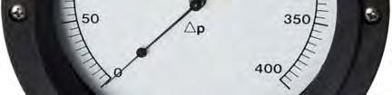

73 BELLOWS STYLE GAUGE Mid-West Instrument 72
74 Mid-West Instrument Bellows Type Differential Pressure Gauges & Switches Model s 105 & 106 Dry Gauge Design with No Internal Liquid Fill BULLETIN NO /12 (SUPERSEDES /11) Industrial Control Over Range Protection high-low and low-high to rated working pressure with use of a bi-directional relief valve Model 105/106 DP Range: 0-10" H2O to 0-30 PSID (25 mbar to 3.0 bar) Diaphragm Bellows design provides a simple, compact, accurate, directacting, low range high accuracy differential pressure indicator. Easier and less expensive to service/repair than competitive units. Working pressures of 500, 1500, 3000, or 6000 PSIG (400 bar). Housing materials: Aluminum, Brass, Carbon Steel, or 316L S.S. Internals: Stainless Steel Diaphragm Bellows. Available: Elastomers: Buna-N, Viton, Neoprene, Ethylene Propylene Mechanical over-range protection high to low and low to high. Weather resistant case of Engineered Plastic / Shatter resistant acrylic lens Panel Mounting Kit Standard Uni-directional or Bi-directional dials are readily available. Gauges are optionally available with one or two switches which offer s the ability to have alarm or control. Model s 105/106 (± 1/2% or ± 1% Full Scale Accuracy) System pressure is applied to the internal volume of a bellows and mechanical linkage assembly. As pressure changes, the bellows and linkage assembly move to cause an electrical signal to be produced or to cause a gauge pointer to move. The major components are a two-piece body, multiple diaphragm/bellows sensing element and over-pressure assembly, a torque tube assembly, a range spring and the gauge front assembly. The body halves provide the pressure containment function. They also clamp the sensing element and over-pressure assembly between the halves, isolating the high side and low side pressures of the system. The high side body half also provides a mount for the torque tube assembly and the gauge front assembly. Model Accuracy Min. P Range Max. P Range Safe Working Pressure PSIG (bar) Optional Switches 105 ±1/2% or 1% 0-10" H20 (0-25 mbar) " H2O (0-200 mbar) (34-400) 1 or ±1/2% or 1% 0-80" H20 (0-200 mbar) 0-800" H20 (0-30 PSID) (34-400) 1 or 2 Model s 105/106 assembly incorporates a bi-directional relief valve which provides over-pressure protection in both directions. When over-pressured from the high side, the valve is opened by a mechanical stop as the sensing element deflects to its maximum travel. When over-pressured from the low side, the spring-loaded valve opens when the differential pressure exceeds its maximum rating. The opening of the valve in either direction equalizes the pressure and protects the unit. A range spring is provided to adjust the spring rate of the system to suit the various differential pressure ranges of the instrument. 73

75 Mid-West Instrument Models 105 & 106 Bellows Type Differential Pressure Switch Options Industrial Control Equipment LOCKED LOGIC" SOLID STATE ALARM-CONTROL FOR ALL 105 & 106 GAUGES SNAP ACTING MICRO-SWITCH for MODEL106 Range: 0-80 to H2O. (NOTE SWITCH OPTIONS FOR 6" DIAL SIZE ONLY) If your application requires switching in addition to local indication, our all solid state "Locked Logic" system is the most accurate available. With no moving cams, levers, etc. it does not affect the accuracy of the gauge on which it is installed. Switch accuracy is the same as the gauge accuracy. Visible set pointers are provided, adjustable to within 5% of full scale of each other. The set points are adjustable from 5 to 95% of full scale. Internal adjustment is standard. 1-2 Independently adjustable switches with Set Point Feedback, SPDT or DPDT Output options, Adjustable deadband option for single SPDT or DPDT output (2 set pointers) Accuracy of Gauge unaffected by the switch. Locked Logic switches require input power to operate. Model 106 can also be equipped with one ore two independently adjustable SPDT snap acting Micro- Switches which can be set on decreasing or on increasing pressure. A switch adjustment screw and a switch lock screw is accessible after removal of the lens and bezel (removal of 4 screws). Interface to the snap acting micro-switch is via color coded 18 AWG flying leads and a ½ FNPT conduit connection. Snap acting Micro switches do not require input power to operate. NOTE: Snap Acting Micro-Switches are not available with Bi-Directional Range Gauges NOTE : It is strongly recommended that a 3-Valve differential pressure manifold be used in plumbing your model 105/106 to your system. Properly used it should insure that your instrument is not over-ranged or damaged by pressure shocks during pressurization. It will later zeroing, ranging and calibration checking. It is a good practice to purge or flush the instrument loop prior to connecting the instrument. OPTION INTERFACE MARKINGS ENVIRONMENTAL COMMENTS A, B 1/2" FNPT Conduit with 24 LNG, 18 AWG Colored Flying Leads, 3/4" FNPT for (2) DPDT Outputs NONE Weather-proof Housing NEMA 4 Requires Input Power to Operate. C, D 1/2" FNPT Conduit with 24 LNG, 18 AWG Colored Flying Leads, 3/4" FNPT for (2) DPDT Outputs Class I, Groups B, C & D Class II, Groups E, F & G Explosion-proof Housing NEMA 7 Requires Input Power to Operate. G, H 1/2" FNPT Conduit with 18 LNG, 18 AWG Colored Flying Leads NONE CSA Listed Weather-proof Housing NEMA 4 Does not require Input Power to Operate. J, K 1/2" FNPT Condulet Enclosure with 18 LNG, 18 AWG Colored Flying Leads NONE 74 CSA Listed Weather-proof Housing NEMA 4 Does not require Input Power to Operate.
76 Mid-West Instrument Standard Dial Ranges Models: 105 & 106 Range Type PSID H2O Kpa Bar " " " " " " " " " 0-200" 0-250" 0-300" 0-400" 0-500" 0-600" The above mentioned ranges are some of the most popular requested today. Mid-West Instrument can provide special un-cataloged dial range requirements. As well as dual scale dials, multiple color dials and special decals. Please consult factory for complete information. Uni-Directional Dial Ranges are available in either LINEAR or SQUARE ROOT FLOW SCALES with any appropriate legend ( I.E. PSID, Kpa, IN H2O, GPM, SCFM, ETC) at no extra charge Model Min. ΔP Range Max. ΔP Range " H 2 0 (0-25 mbar) " H2O (0-200 mbar) " H 2 0 (0-200 mbar) 0-800" H 2 0 (0-30 PSID) (0-2 bar) LINEAR Bi-Directional Dials are available with any appropriate Legend at No Charge Standards: Models 105/106 gauges either conform to and/or are designed to the requirements of the following standards: ASME B NACE MR0175 CSA-C22.2 No and 30 SAE J514 ASME B NEMA Std. No. 250 EN UL Std. No. 50,508 and
 Range 105: 0-10 IN H20 to 0-79.")
77 Standard Model Specifications: 105-FE-00-OO / 106-FE-00-OO 1500 PSIG Working Pressure, Aluminum Body, Stainless Steel Bellows, Stainless Steel Internals Buna-N Seals, ¼ FNPT Dual Top & Bottom Connections, 6 Uni-Directional Round Dial, Weather Resistant Engineered Plastic Case with Shatter Resistant Acrylic Lens, Accuracy ±1% Full Scale (Ascending) Range 105: 0-10 IN H20 to IN H20 (0-.4 PSID to PSID) Range 106: 0-80 IN H20 to IN H20 (0-3 PSID to 0-30 PSID) Basic Model Range: 2 F G M N Q R T X 1500 PSIG, Aluminum Body, Stainless Steel Internals 3000 PSIG, Aluminum Body, Stainless Steel Internals Material (Not All Options Available in Combination with other Options) 1500 PSIG, Mild Carbon Steel Body, Stainless Steel Internals 3000 PSIG, Mild Carbon Steel Body, Stainless Steel Internals 1500 PSIG, 316 Stainless Steel Body, Stainless Steel Internals 3000 PSIG, 316 Stainless Steel Body, Stainless Steel Internals 6000 PSIG, 316 Stainless Steel Body, Stainless Steel Internals 1500 PSIG, Brass Body, Stainless Steel Internals Y 500 PSIG, Brass Body, Stainless Steel Internals 3 Dial Size Type E Accuracy ±1% Full Scale Uni-Directional Dial w/engineered Plastic Dial Case (Standard) F Accuracy ±1% Total Span Bi-Directional Dial w/engineered Plastic Dial Case G Accuracy ±1/2% Full Scale Uni-Directional Dial w/engineered Plastic Dial Case (30 WC & above only)** Z Special (Un-coded Options) Note **G Option not available for square root dials 4 Seal Materials 0 Buna-N (Standard) 1 Viton -A Registered Trademark of Dupont 5 Neoprene 9 Special (Un-coded Options) 5 Process Connections 0 1/4" FNPT Top & Bottom Connections (Standard) 9 Special (Un-coded Options) Proof Pressure: Two times rated working pressure or 10,000 PSI whichever is lower at ambient temperature. Temperature Limits: Gauge Only -40 F (-40 C) to +200 F (+95 C) Locked Logic Switch -40 F (-40 C) to +160 F (+70 C) Micro Switch -20 F (-29 C) to +185 F (+85 C) These limits are based on the entire instrument being saturated to these temperatures. System (process) temperatures may exceed these limitations with proper installation. Contact 76our customer service representative for details.
78 Standard Model Specifications continued Model 105 / Additional Options O NONE F G H J K N Q S T U V W Y Carbon Steel 2" Pipe Mounting Kit Stainless Steel 2" Pipe Mounting Kit 1/4" Carbon Steel Compression Tube Fittings 1/4" Stainless Steel Compression Tube Fittings 1/2" FNPT Stainless Steel Adapters NACE (Available for Aluminum & Stainless Steel Gauge Bodies only) CRN (Canadian Registration Number) Only available on Models 105Q & 106Q Shatter Proof Glass Lens Oxygen Cleaning Stainless Steel Tag with S.S. Wire Stainless Steel Tag and S.S. Screw Wall Mount Kit 4-1/2" Dial Case Z Special (Un-coded Options) 7 Electrical Configurations Note: G,H,J & K switch option (high port on right when facing dial) A B C D G H J K One (1) Switch in Weather Proof enclosure Two (2) Switches in Weather Proof enclosure One (1) Switch in explosion proof enclosure Class 1, Groups B, C, & D (Pipe Mounting Kit Standard) Two (2) Switch in explosion proof enclosure Class 1, Groups B, C, & D (Pipe Mounting Kit Standard) One (1) Micro-Switch in Weather Resistant Enclosure (2) (MODEL " to H2O only) Accuracy ±2% Two (2) Micro-Switches in Weather Resistant Enclosure (MODEL " to H2O only) 0-80" - 199" H2O Accuracy ±4% / 0-200" H2O and above Accuracy ±2% (1) (2) One (1) Micro-Switch in Weather Resistant Housing with Condulet Enclosure (2) (MODEL " to H2O only) Accuracy ±2% Two (2) Micro-Switches in Weather Resistant Housing with Condulet Enclosure (MODEL " to H2O only) 0-80" - 199" H2O Accuracy ±4% / 0-200" H2O and above Accuracy ±2% (1) (2) Z Special (Un-coded Options) (1) Accuracies & repeatability values for (2) switch units are based upon (1) switch set low (approx. 25% for FSR) and (1) switch set high (2) CSA Listed, Type 4, Industrial Control Equipment 8 "Input Options" Electrical Specifications (Select (1) input and (1) output option) A B C N 8-28 Vdc 115 VAC 50/60 Hz 220/240 VAC 50/60Hz No Input Required for Micro-Switch Options: G, H, J & K Z Special (Un-coded Options) 9 "Output Options" (Resistive Load) A C D E M Z SPDT Relays SPST Relays (Resistive load) VDC, 115/230 VAC (50/60 Hz) (1/2 NPT, 24 Flying Leads standard interface) (1/2 NPT, 24 Flying for two (2) DPDT switches) Adjustable Deadband, one (1) SPDT output (two (2) control switches only) Adjustable Deadband, one (1) DPDT output (two (2) control switches only) Micro Switch Electrical Interface: 18", 18 Awg, 600 V, 105 C / Color coded wire leads from 1/2" FNPT Connection SPDT Micro-Switch Contact Ratings:(MAX) 4 30 VDC / 3 240VAC / VAC Special (Un-coded Options) Factory preset switches at no charge (specify setting) NOTE: The use of Diaphragm seals is not recommended for Model 105/106 gauges. Attempts to install such seals on these gauges will void warranty. Contact factory for bi-directional scales 77

 Stainless Steel Gauge Front, Stainless Steel Body with Shatter-Proof Glass Lens.")


79 BULLETIN NO. 105/HYD/11 Mid-West Instrument Model 105 TANK LEVEL GAUGE for LIQUID HYDROGEN SERVICE No Liquid Fill required Over-Range Protection High over Low and Low over High! Benefits: Mid-West Model 105 bellows design provides a simple, compact, accurate, direct-acting, low range differential pressure level indicator. Accuracy ±1% of Full Scale Range Model 105: 0-10 H 2 O to 0-50 H 2 O (25 mbar to 125 mbar) Stainless Steel Gauge Front, Stainless Steel Body with Shatter-Proof Glass Lens. Provides superior safety and corrosion resistance. Dry gauge design with no internal liquid fill No costly clean up from liquid fill leaking No chance of unacceptable or incompatible fill fluid being in the gauge. No gauge damage/accuracy loss caused by liquid fill expansion or contraction when exposed to temperature extremes in Hydrogen level applications. Single bellows design is more compact and light weight. Substantial weight savings over competitive range gauges. Can be panel mounted in a one piece panel. Can be mounted on tanks using std. 2 pipe mount brackets or ¾ pipe nipple brackets. Mid-West Instrument performs Helium leak testing on units for Hydrogen service. Product Description: The Model 105 design is an all-stainless steel differential pressure gauge capable of operating at low differential pressures. Safe working pressure is 1500 PSIG standard. The DPI is equipped with a Bi-directional Over Pressure Relief Valve (OPV). When the Differential Pressure exceeds 130% of the range the OPV equalizes the pressure between the Hi and Lo side s ¼ FNPT Dual top and bottom connections are provided as standard. The DPI is also equipped with a Micro adjust pointer, If necessary the pointer can be re-zeroed. Body is made of stainless steel with 316 Stainless Steel internals. Viton Seals are provided as standard with other elastomers available. Dial is 6 diameter with white lettering on a black dial.(white dial with black lettering optional) The temperature limits are rated at -40 C to 200 F. Proof pressure is two times working pressure at ambient temperatures. 78
80 Product Features: Ability to create custom dials for horizontal and vertical tanks Various Dial layouts available: Single Scale, Dual Scale and Tri-Scale Micro-Adjust pointer (if necessary the pointer can be re-zeroed) In house Oxygen Cleaning (optional) Private Labeling (optional) White ink on Black dial or Black ink on White dial Industry best lead time reduces inventory requirements Accuracy DP Range Safe Working Pressure Body Material Dial Case & Bezel Internals Port Seals Dial Standard Mounting Optional Mounting Warranty Gauge Specifications 105 ±1% of Full Scale 0-10" H2O to 0-50" H2O (25 mbar to 125 mbar) 1500 PSIG (3000 PSIG optional) 316 Stainless Steel 316 Stainless Steel 316 Stainless Steel Multiple Bellows Dual Top and Bottom, 1/4" FNPT connections with optional snubbers Viton Standard, other elastomers available 6" Black dial with White lettering (White dial with Black lettering optional) Panel Mountable 2" Pipe Mount Five Year Proof Pressure: Two times working pressure at ambient temperatures Temperature Limits: -40 F (-40 C) to 200 F (93 F) Standards: ASME B CSA-C22.2 No.14 NEMA Std. No. 250 ASME B UL Std. No. 50 SAE J514 79

81 BOURDON TUBE STYLE GAUGE Mid-West Instrument 80
82 BULLETIN NO. 109/11 (SUPERSEDES BULLETIN NO. 109/05) Mid-West Instrument Bourdon Tube Type Differential Pressure Gauge & Switches Model 109 LOCKED LOGIC ALARM CONTROLS (Available with 1 or 2 switches for alarm & control) Over Range Protection high-low and low-high to rated working pressure by use of a bi-directional relief valve Model 109 DP Range: 0-15 PSID (0-1.0 bar) to PSID (0-400 bar) Bourdon Tube design provides a simple, compact, accurate, directacting, high accuracy differential pressure indicator. Easier and less expensive to service/repair than competitive units. Working pressures of 500, 1500, 3000, or 6000 PSIG (400 bar). Housing materials: Aluminum, Brass, Carbon Steel, or 316L Stainless Steel Internals: Copper-Alloy or Stainless Steel Bourdon Tube. Available Elastomers: Buna-N, Viton, Neoprene, Ethylene Propylene Mechanical over-range protection to maximum working pressure Weather resistant dial case of Engineered Plastic with Shatter resistant acrylic lens Panel Mounting Standard Uni-directional or Bi-directional dials are readily available. Gauges are optionally available with one or two switches which offer s the ability to have alarm or control. Model 109 (± 1/2% or ± 1% Full Scale Accuracy) System pressure is applied to the inside of a slightly flattened arc- shaped tube. As pressure increases, the tube tends to restore to its original round cross-section. This change in cross-section causes the tube to straighten. Since the tube is permanently fastened at one end, the tip of the tube traces a curve that is the result of the change in angular position with respect to the center. Powered by a test quality Bourdon Tube assembly, the assembly is encapsulated in a high pressure chamber that is fitted with a pressure connection to the inside of the Bourdon Tube and a second connection to the pressure chamber. Model Accuracy Min. P Range Max. P Range Safe Working Pressure PSIG (bar) Optional Switches 109 ±1/2% or 1% 0-15 PSID (0-1.0 bar) PSID (0-400 bar) (34-400) 1 or 2 Model 109 assembly incorporates a bi-directional relief valve which provides over-pressure protection in both directions. When over-pressured from the high side, the valve is opened by a mechanical stop as the sensing element deflects to its maximum travel. When over-pressured from the low side, the spring-loaded valve opens when the differential pressure exceeds its maximum rating. The opening of the valve in either direction equalizes the pressure and protects the unit. A range spring is provided to adjust the spring rate of the system to suit the various differential pressure ranges of the instrument. 81
83 Bourdon Tube Type Differential Gauge Switch Options Model 109 "LOCKED LOGIC" SOLID STATE ALARM-CONTROL FOR ALL 109 GAUGE (NOTE - 6" DIAL SIZE ONLY) If your application requires switching in addition to local indication, our all solid state "Locked Logic" system is the most accurate available. With no moving cams, levers, etc. it does not affect the accuracy of the gauge on which it is installed. Switch accuracy is the same as the gauge accuracy. Visible set pointers are provided, adjustable to within 5% of full scale of each other. The set points are adjustable from 5 to 95% of full scale. Internal adjustment is standard. 1-2 Independently adjustable switches with Set Point Feedback. SPDT or DPDT Output options, Adjustable deadband option for single SPDT or DPDT output (2 set pointers) Accuracy of Gauge unaffected by the switch OPTION INTERFACE MARKINGS ENVIRONMENTAL COMMENTS A, B C, D 1/2" Conduit with 24" 18 AWG Color Coded Flying Leads 3/4" FNPT for (2) DPDT Outputs None NEMA 4X 1/2" Conduit with 24" 18 AWG Color Coded Flying Leads 3/4" FNPT for (2) DPDT Outputs NONE Class I, Div 1, Groups B, C, & D Class II, Div 1, Groups E, F, & G. NEMA 4X NEMA 7(OPTIONAL) Requires Input Power to operate. Explosion-proof enclosure. Requires Input Power to Operate. "MODEL 109 ELECTRICAL CONFIGURATIONS A One (1) Switch in Weather Proof enclosure B Two (2) Switches in Weather Proof enclosure C One (1) Switch in explosion proof enclosure Class I, Groups B, C, & D (Pipe Mounting Kit Standard) D Two (2) Switch in explosion proof enclosure Class I, Groups B, C, & D (Pipe Mounting Kit Standard) "INPUT OPTIONS" ELECTRICAL SPECIFICATIONS (Select (1) input and (1) output option) A 8-28 Vdc B 115 VAC 50/60 Hz C 220/240 VAC 50/60Hz Z Special (Un-Coded Options) "OUTPUT OPTIONS" ELECTRICAL SPECIFICATIONS (Resistive Load) (Resistive load) VDC, 115/230 VAC (50/60 Hz) (1/2 NPT, 24 Flying Leads standard interface) (1/2 NPT, 24 Flying for two (2) DPDT switches) A SPDT Relays C SPST Relays D Adjustable deadband, one (1) SPDT output (two (2) control switches only) E Adjustable deadband, one (1) DPDT output (two (2) control switches only) Factory preset switches at no charge (Specify Setting) Proof Pressure: Two times rated working pressure at ambient temperature Temperature Limits: Gauge Only -40 F (-40 C) to +200 F (+95 C) Locked Logic Switch -40 F (-40 C) to +160 F (+70 C) These limits are based on the entire instrument being saturated to these temperatures. System (process) temperatures may exceed these limitations with proper installation. Contact our customer service representative for details. Standards: Model 109 gauge either conforms to and/or is designed to the requirements of the following standards: ASME B NACE MR0175 CSA-C22.2 No and 30 SAE J514 ASME B NEMA Std. No. 250 EN UL Std. No. 50,508 and
84 Mid-West Instrument Standard Dial Ranges Model: 109 Range Type PSID H2O Kpa Bar Bi-Directional Dual Scale " PSID 0-15 PSID & 0-1 Kg/cm " PSID 0-25 PSID & Kg/cm " PSID 0-30 PSID & Kpa PSID 0-50 PSID & Kpa PSID 0-60 PSID & Kpa PSID PSID & Kpa PSID PSID & 0-7 Kg/cm PSID PSID PSID PSID PSID Up to 6000 The above mentioned ranges are some of the most popular requested today. Mid-West Instrument can provide special un-cataloged dial range requirements. As well as dual scale dials, multiple color dials and special decals. Please consult factory for complete information. Model Min. ΔP Range Max. ΔP Range PSID (0-1.0 bar) PSID (0-400 bar) Uni-Directional Dial Ranges are available in either LINEAR or SQUARE ROOT FLOW SCALES with any appropriate legend ( I.E. PSID, Kpa, IN H2O, GPM, SCFM, ETC) at no extra charge LINEAR Bi-Directional Dials are available with any appropriate Legend at No Charge
 Range: 0-15 PSID to 0-6000 PSID (0-1.")
 1500 PSIG, Aluminum Body, S.S. Internals (1/4 FNPT Connections / 316 Stainless Steel) 3000 PSIG, Aluminum Body, S.S. Internals (1/4 FNPT Connections / 316 Stainless Steel) 1500 PSIG, Mild Carbon Steel Body, S.")
85 Standard Model Specifications: 109-FE-00-OO 1500 PSIG Working Pressure, Aluminum Body, Stainless Steel Bourdon Tube, Stainless Steel Internals Buna-N Seals, ¼ FNPT Back Connections (Stainless Steel), 6 Uni-Directional Round Dial, Weather Resistant Engineered Plastic Case with Shatter Resistant Acrylic Lens, Accuracy ±1% Full Scale (Ascending) Range: 0-15 PSID to PSID (0-1.0 bar to bar) Basic Model Range: 2 Material C D F G M N Q R T U V X 1500 PSIG, Aluminum Body, Copper Alloy Internals (1/4 FNPT Connections / Carbon Steel) 3000 PSIG, Aluminum Body, Copper Alloy Internals (1/4 FNPT Connections / Carbon Steel) 1500 PSIG, Aluminum Body, S.S. Internals (1/4 FNPT Connections / 316 Stainless Steel) 3000 PSIG, Aluminum Body, S.S. Internals (1/4 FNPT Connections / 316 Stainless Steel) 1500 PSIG, Mild Carbon Steel Body, S.S. Internals (1/4 FNPT Connections / 316 Stainless Steel) 3000 PSIG, Mild Carbon Steel Body, S.S. Internals (1/4 FNPT Connections / 316 Stainless Steel) 1500 PSIG, 316 Stainless Steel Body, S.S. Internals (1/4 FNPT Connections / 316 Stainless Steel) 3000 PSIG, 316 Stainless Steel Body, S.S. Internals (1/4 FNPT Connections / 316 Stainless Steel) 6000 PSIG, 316 Stainless Steel Body, S.S. Internals (1/4 FNPT Connections / 316 Stainless Steel) 1500 PSIG, Brass Body, Copper Alloy Internals (1/4 FNPT Connections / Brass) 500 PSIG, Brass Body, Copper Alloy Internals (1/4 FNPT Connections / Brass) 1500 PSIG, Brass Body, S.S. Internals (1/4 FNPT Connections / 316 Stainless Steel) Y 500 PSIG, Brass Body, S.S. Internals (1/4 FNPT Connections / 316 Stainless Steel) 3 Dial Size Type E Accuracy ±1% Full Scale Uni-Directional Dial w/engineered Plastic Dial Case (Standard) F Accuracy ±1% Total Span Bi-Directional Dial w/engineered Plastic Dial Case (±3% above PSI) G Accuracy ±1/2% Full Scale Uni-Directional Dial w/engineered Plastic Dial Case (Not available above 1000 PSID) Z Special (Un-coded Options) Note: **G Option not available for square root dials 4 Seal Materials 0 Buna-N (Standard) 1 Viton -A Registered Trademark of Dupont 2 Neoprene 5 Ethylene Propylene 6 Perfluorelastomers 9 Special (Un-coded Options) 5 Process Connections 0 1/4" FNPT Back Connections (Standard) 5 1/2" FNPT Back Connections (Stainless Steel) 9 Special (Un-coded Options) 84
86 Standard Model Specifications continued Model Additional Options O NONE B Drain & Bleed Connections (1/8" FNPT) Brass C Drain & Bleed Connections (1/8" FNPT) 316 Stainless Steel F Carbon Steel 2" Pipe Mounting Kit (Standard on Explosion Proof Locked Logic Units) H 1/4" Carbon Steel Compression Tube Fittings J 1/4" Stainless Steel Compression Tube Fittings L Liquid Fill M Maximum Indicator Follower Pointer (Not available with Liquid fill option) N NACE (Available for Aluminum & Stainless Steel Gauge Bodies only) Q CRN (Canadian Registration Number) Only available on Models 109F, M or Q. S Shatter Proof Glass Lens T Oxygen Cleaning U Stainless Steel Tag with S.S. Wire V Stainless Steel Tag and S.S. Screw W Wall Mount Kit Y 4-1/2" Dial Case Z Special (Un-coded Options) 7 Electrical Configurations O NONE A One (1) Switch in Weather Proof enclosure B Two (2) Switches in Weather Proof enclosure C One (1) Switch in explosion proof enclosure Class I, Groups B, C, & D (Pipe Mounting Kit Standard) D Two (2) Switch in explosion proof enclosure Class I, Groups B, C, & D (Pipe Mounting Kit Standard) 8 "Input Options" Electrical Specifications (Select (1) input and (1) output option) A 8-28 Vdc B 115 VAC 50/60 Hz C 220/240 VAC 50/60Hz Z Special (Un-coded Options) 9 "Output Options" (Resistive Load) (Resistive load) VDC, 115/230 VAC (50/60 Hz) (1/2 NPT, 24 Flying Leads standard interface) (1/2 NPT, 24 Flying for two (2) DPDT switches) A SPDT Relays C SPST Relays D Adjustable deadband, one (1) SPDT output (two (2) control switches only) E Adjustable deadband, one (1) DPDT output (two (2) control switches only) Z Special (Un-coded Options) Not All Options Available in Combination with other Options 85


87 TANK LEVEL GAUGES Mid-West Instrument 86
 Model 116, 0-70 H 2 O to 0-800 H 2 O (2.5 PSID to 30 PSID) Model 115/116 multiple diaphragm/bellows design provides a simple, highly accurate, direct-acting, differential pressure indicator.")
88 BULLETIN NO /11 Mid-West Instrument Bellows Type Tank Level Differential Pressure Level Gauge & Switch Model 115/116 Model 115, 0-10 H 2 O to H 2 O (25 mbar to 2.5 PSID) Model 116, 0-70 H 2 O to H 2 O (2.5 PSID to 30 PSID) Model 115/116 multiple diaphragm/bellows design provides a simple, highly accurate, direct-acting, differential pressure indicator. Full Scale Accuracy of ±1%. Typical applications include; Level measurement in closed tanks for the Industrial Liquid Gas Industry. Use with gaseous and liquid media, provide they are not highly viscous. Various Dial scales available to match a wide variety of gases such as He, Ar, O2, N2, CO2, Helium and Hydrogen BENEFITS:: Engineered Plastic gauge front and stainless steel body bolts provide corrosion resistance in over the road Trailers outdoor and salt air environments. Up to a 30 lb. weight savings over competitive Liquid Helium range gauges Allows more product to be transported in mobile trailers Easier and less labor to panel mount Low & High range capabilities Ideal for He, Ar, O2, N2, CO2, Helium and Hydrogen tank level applications For use on Stationary, Over the Road, ISO/IMO containers and LNG bulk tanks Industry best lead time reduces inventory requirements Adaptable to wide variety of mounting configurations Private Brand and Custom Dials available: Single Scale, Dual Scale, and Tri-Scale 87
 1500 PSIG ±1% of Full Scale 0-70\" H2O to 0-800\" H2O (2.")
89 Model 115/116 Tank Level Gauge H2O Single Switch Optional ¾ FNPT Stub Mount Shown Model H2O / Single Scale Ar, O2, N2 Tri-Scale Dial Accuracy DP Range Safe Working Pressure 115 ** " H2O to " H2O (25 mbar to 2.5 PSID) 1500 PSIG ±1% of Full Scale 0-70" H2O to 0-800" H2O (2.5 PSID to 30 PSID) 500 PSIG (Standard) 1000 PSIG (Optional) Body Material Brass Brass Internals 316 S.S. Welded Multiple Diaphragm 316 S.S. Convoluted Bellows Port Seals Dial Dual Top and Bottom, 1/4" FNPT connections with optional snubbers Viton Standard, other elastomers available 6" Black dial with White lettering (White dial with Black lettering optional) Warranty One Year **Model 116 Snap Acting Micro-Switch for Alarm (optional) Ranges: 0-80" H2O & above. Aluminum, Carbon Steel, & Stainless Steel Body Materials Available... Ask about Model's 105, and 106 ( SWP of 1,500 & 3,000 PSIG) 88
90 O.E.M GAUGES Mid-West Instrument 89

 Differential Pressure Range 0-5 PSID (0-0.35 bar) to 0-20 PSID (0-1.4 bar) (127) Differential Pressure Range 0-25 PSID (0-1.")
91 BULLETIN NO /11 (SUPERSEDES BULLETIN NO /00) Mid-West Instrument O.E.M Piston Type Differential Pressure Gauges & Switches Models 126 & 127 Common Applications Filter Monitoring Strainer Monitoring Water System Applications Refrigerant Filtration Systems 126/127 Specifications: (126) Differential Pressure Range 0-5 PSID ( bar) to 0-20 PSID (0-1.4 bar) (127) Differential Pressure Range 0-25 PSID (0-1.7 bar) to PSID (0-7 bar) Accuracy ±5% Full Scale Ascending Dial Size o Single 1-1/4" x 2-1/4" Oval (Std.) o Dual 1-1/4" x 2-1/4" Oval (Opt.) Working Pressure 3,000 PSIG (200 bar) Operating Temp. -40º F To +200º F (-40ºC to 93ºC) Body Material - Aluminum (Std.), 316/316L SS (Opt.) Internal Materials Stainless Steel Elastomers - Buna-N (Std), Viton *, Neoprene, Ethylene-Propylene, Switch Option o SPDT 3W, 125 VAC/VDC, 0.25 Amp o SPST 60W, 240 VAC/VDC, 3 Amp Switch Mounting Clamp On, Stick On Flat Pack Process Connections 1/8" FNPT Bottom (Std) 1/8" FNPT End Conn. (Opt.) Dimensions 1.25H" x 1.62W" x 2.48L" Weight 0.5# * Viton is a Registered Trademark of DuPont Dow Elastomers Model 126/127 Bottom Connections Shown 90
92 Model PSIG Working Pressure, S.S. Piston, Aluminum or S.S. Body & End Plug, Accuracy ±5% F.S. (Ascending), 1/8 FNPT Bottom Mount, Range: 0-5 PSID thru 0-20 PSID Model PSIG Working Pressure, S.S. Piston, Aluminum or S.S. Body & End Plug, Accuracy ±5% F.S. (Ascending), 1/8 FNPT Bottom Mount, Range: 0-25 PSID thru PSID Basic Model Range: 2 Material A Aluminum Body / Stainless Steel Piston S 316 S.S Body / Stainless Steel Piston Z Special (Un-coded Options) 3 Dial Size & Type W One X Two Z Special (Un-coded Options) 4 Seal Materials 0 Buna-N 1 Viton -A Registered Trademark of Dupont 2 Neoprene 5 Ethylene Propylene 9 Special (Un-coded Options) 5 Process Connections 0 1/8" FNPT Bottom Connections 2 1/8" FNPT End Connections 9 Special (Un-coded Options) 6 Options O None Z Special (Un-coded Options) 7 Electrical Configuration A (1) Switch (clamp-on) Switch adjustable range10 to 100% B (2) Switches (clamp-on) Switch adjustable range10 to 100% C (1) Switch (Flat Pack) Non-Adjustable D (1) Switches (Flat Pack) Non-Adjustable E (1) Switch (clamp-on) Switch adjustable range ±15% F (2) Switches (clamp-on) Switch adjustable range ±15% Z Special (Un-coded Options) 8 Electrical Specifications A SPDT 3W.025 Amp 125 VAC/VDC (Flat-Pack) C SPST 60W 3.0 Amp 240 VAC/VDC (Clamp-On &Flat-Pack) Z Special (Un-coded Options) * Special OEM Box car number will be assign upon order. *Gauges must be puchased in quantities of 25 units. 91

93 BULLETIN NO. 146/11 (SUPERSEDES BULLETIN NO. 146/00) Mid-West Instrument O.E.M Diaphragm Type Differential Pressure Gauge & Switch Model 146 Common Applications Filter monitor for initiating backwash cycles Strainer Monitoring Water Systems applications Hydro applications Pump performance monitoring Refrigerant filtration systems Replacement indicating switch for competitor switches that do not offer local indication Specifications: Differential Pressure 0-50" H2O (0-125 mbar) to 0-30 PSID (0-2.0 bar) Accuracy ±5% Full Scale Ascending Dial Size o Single 1-1/4" x 2-1/4" Oval (Std.) o Dual 1-1/4" x 2-1/4" Oval (Opt.) Working Pressure 1,000 PSIG (200 bar) Operating Temp. -40º F To +200º F (-40ºC to 93ºC) Body Material Aluminum, Brass & 316L Stainless Steel Internal Materials Stainless Steel Elastomers - Buna-N (Std), Viton *, Silicone, Neoprene (25 PSID & Below), Ethylene Propylene Switch Option o SPDT 3W, 125 VAC/VDC, 0.25 Amp o SPST 60W, 240 VAC/VDC, 3 Amp Process Connections 1/8" FNPT Bottom Dimensions 1.7H" x 2.5W" x 2.9L" Weight 2.5# * Viton is a Registered Trademark of DuPont Dow Elastomers Operation: Differential pressure is sensed by flexible elastomer diaphragm and a calibrated spring. A magnetic coupling transmits the sensing element motion to an indicating pointer. This prohibits the possibility of fluid leaking into the gauge case, while assuring total isolation of the process fluid within the pressure capsule. The diaphragm assures total separation between high and low pressure signals. It is totally supported at full travel in either direction. Temperature Limits: -40 F (-40 C) to 200 F (93 C). These limits are based on the entire instrument being saturated to these temperatures. System (process) temperatures may exceed these limitations with proper installation. Contact our customer service representative for details. 92
94 Model PSIG Working Pressure, Buna-N Diaphragm, Aluminum, Brass or 316 Stainless Steel Body, 316 S.S. Internal Metal Parts Accuracy ±5% F.S. (Ascending), 1/8 FNPT Bottom Mount Range: 0-50 H2O thru 0-30 PSID Basic Model Range: 2 Material A Aluminum Body B Brass Body S 316 Stainless Steel Body Z Special (Un-coded Options) 3 Dial Size & Type W One X Two Z Special (Un-coded Options) 4 Seal Materials 0 Buna-N 1 Viton -A Registered Trademark of Dupont 2 Silicone 4 Neoprene (25 PSID & below) 5 Ethylene Propylene 9 Special (Un-coded Options) 5 Process Connections 0 1/8" FNPT Bottom Connections (STD) 2 1/8" FNPT Back Connections 6 Options O None Z Special (Un-coded Options) 7 Electrical Configuration A (1) Switch (non-adjustable) B (2) Switches (non-adjustable) C (1) Switch (non-adjustable) DIN Plug-In Connector D (1) Switch (Flat Pack) Non-Adjustable E (2) Switches (Flat Pack) Non-Adjustable F (1) Switch (Flat Pack) Switch adjustablility ±15% G (2) Switches (Flat Pack) Switch adjustablility ±15% Z Special (Un-coded Options) 8 Electrical Specifications A SPDT 3W.025 Amp 125 VAC/VDC (Flat-Pack) C SPST 60W 3.0 Amp 240 VAC/VDC (Clamp-On &Flat-Pack) Z Special (Un-coded Options) **Product of switching voltage and current shall not exceed the power rating. Ratings are resistive loads. * Special OEM Box car number will be assign upon order. *Gauges must be puchased in quantities of 25 units. 93
95 Mid-West Instrument O.E.M Piston Type Differential Pressure Indicator Model 444 BULLETIN NO. 444/OEM/11 (Supersedes Bulletin NO. 444/00) Model 444 Series differential pressure indicator offers a simple, yet functional design for use with filters, strainers, etc. This low cost indicator makes the perfect alternative to more costly differential pressure gauges where readability, small size and price are important considerations. All dimensions in inches. Minimum Order Quantity 50 UNITS Transition Points Model Number DP Range Piston Indicator all PSID 3.75 PSI 5.25 PSI PSID 7.75 PSI 10.5 PSI PSID PSI 15.5 PSI PSID PSI 27.0 PSI OEM Applications Quoted Please call with specifications. SPECIFICATIONS: Comments: Maximum Working Pressure 300 PSIG Differential Pressure Ranges: **Contact factory for additonal ranges 0-5 thru 0-25 PSID** Accuracy ± 5% of Rated Differential Pressure Range Calibrated at Color Transitions Operating Temperature (Max.) 93 C (200 F) MATERIALS OF CONSTRUCTION: Body Material Glass Filled Nylon (GFN) 6/6 Body Wetted Internals Glass Filled Nylon & Stainless Steel Elastomers Lens Buna-N Clear Nylon INTERFACE: Process Connection: Slotted Hex Bolt 3/8-24 UNF Chamfered Bolts Ease Installation Flow Direction Identified on Indicator Body. Arrow Points to Low Pressure Port. 94
96 Mid-West Instrument O.E.M Diaphragm Type Differential Pressure Indicator Model 555 BULLETIN NO. 555/OEM/11 (SUPERSEDES BULLETIN NO. 555/444/02) Colored bands allow you to quickly identify pressure drop across element. Divided into three sections, each clearly marked for ease of understanding. Commonly used to indicate when to change or clean a filter. Example: 555A-10.0 changes from green to yellow at 5 PSID and from yellow to red at 7.5 PSID. Accuracy is ±5% Full Scale 50 Pieces per Shipment Minimum Order Quantity Model DP Transition Points Number Range Green Yellow Red PSID PSID PSID PSID PSID PSID PSID PSID OEM applications quoted. Please call with specifications. SPECIFICATIONS: Comments: Pressure (Ratings) Maximum Working 300 PSIG Maximum Differential 150 PSID Accuracy ± 5% of Rated Differential Pressure Range Calibrated at Color Transitions Operating Temperature (Max.) 93 C (200 F) Materials of Construction Body Material Glass Filled Nylon (GFN) Wetted Internals Stainless Steel, Ceramic, & GFN Elastomers Buna Movement Magnetic Piston and Follower Pointer Dial Plastic Lens with 3 Color Dial INTERFACE: Process Connection: ¼ FNPT End Connections. To switch HIGH and LOW pressure connections: Remove Indicator from base and rotate Retighten plastic bolts to inch pounds. Flow Direction Identified on Dial. Arrow Points to Low Pressure Port. 95
 Gauge Features: Safe Working Pressure: 1000 PSIG (69 bar). Aluminum or 316 / 316L SS Gauge Body.")
 available Dial: 0.")
97 BULLETIN NO. 522/OEM/11 (SUPERSEDES BULLETIN NO. 522/06) Mid-West Instrument O.E.M Diaphragm Type Differential Pressure Gauges & Switches Model 522 RANGE: 0-5 P.S.I.D. TO 0-50 P.S.I.D. (.3 bar to 3.4 bar) Gauge Features: Safe Working Pressure: 1000 PSIG (69 bar). Aluminum or 316 / 316L SS Gauge Body. Wetted Parts: 316 SS, Ceramic, & Acetal components Seal & Diaphragm Material: Buna-N or Viton ¼ FNPT Process Connections (End Connected) Weather-resistant construction standard. Dial Accuracy ± 5% standard. Switch Only (No Dial) available Dial: 0.80 weatherproof multicolored 2-1/2 Optional Dial Size Switch Features: Switches are optional Hermetically Sealed Switch Outputs up to 3 amps in SPST and up to.25 Amp in SPDT configuration. Switch Adjustable from 40% - 95% of Range * Up to 240 VAC/VDC voltage ratings Available with Flat Pack case with Jacketed Flying Leads or with DIN IP65 / NEMA 4X Plug-in Connector. Optional Switch Set Feedback Decal Switch Location Top or Bottom CE Marking for Compliance with the Low Voltage Directive is available upon request. *Dependent on selected switch option. Operation: Differential pressure is sensed by flexible elastomer diaphragm and a calibrated spring. A magnetic coupling transmits the sensing element motion to an indicating pointer. This prohibits the possibility of fluid leaking into the gauge case, while assuring total isolation of the process fluid within the pressure capsule. The diaphragm assures total separation between high and low pressure signals. It is totally supported at full travel in either direction. Temperature Limits: -40 F (-40 C) to 200 F (93 C). These limits are based on the entire instrument being saturated to these temperatures. System (process) temperatures may exceed these limitations with proper installation. Contact our customer service representative for details. Standards: All Model 522 Series differential pressure gauges either conform to and/or are designed to the requirements of the following standards: ASME B NACE MR0175, ASME B NEMA Std. 250, EN UL Std. No. 50 & 508, CSA-C22.2 No. 14 Factory Preset of switches available at no charge (Specify switch setting on the order) The use of diaphragm seals is not recommended. Attempts to install such seals on this gauge will void the warranty 96
98 Ordering Information: Contact factory for desired configuration options & pricing. Dimensional: TEMPERATURE LIMITS: -40 F (-40 C) to 200 F (93 C). These limits are based on the entire instrument being saturated to these temperatures. System (process) temperatures may exceed these limitations with proper installation. Contact our customer service representative for details. STANDARDS: All Model 522 Series differential pressure gauges either conform to and/or are designed to the requirements of the following standards: ASME B NACE MR0175 ASME B NEMA Std. 250 EN UL Std. No. 50 & 508 CSA-C22.2 No. 14 Factory Preset of switches available at no charge (Specify Setting on the order) The use of diaphragm seals is not recommended. Attempts to install such seals on this gauge will void the warranty 97

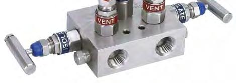
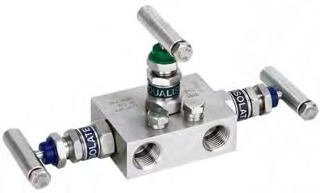
99 GAUGE ACCESSORIES Mid-West Instrument 98


100 Bulletin No. MFLD/11 Mid-West Instrument 3 & 5 Valve Differential Pressure Manifolds # Valve Mini- Manifold # Valve Manifold # Valve Manifold 3 & 5 valve manifolds are designed for applications where direct mounting to an instrument is impractical or undesirable. The manifold is mounted to the lines from the instrument and signal rather than directly to instrument. Bubble tight shut-off, lightweight, super strong construction, compact designs that require less parts, chrome plated stems that prevent galling and stripping- these valves are built to perform under pressure. That s why in some of the most rigid tests, manifolds provided by Mid-West Instrument consistently meet or exceed industry standards. Pressure rating: 6000 PSIG ( F (115 C) Instrument Connections: Std. 3 & 5 Valve = ½ FNPT / 3-Valve Mini-Manifold:= ¼ FNPT Process Connections: Std. 3 & 5 Valve = ½ FNPT / 3-Valve Mini-Manifold:= ¼ FNPT Dust cap: Protects spindle threads from dirt & dust. Gland Nut & Lock Nut: Adjusts the packing compression to provide leak free operation even on vacuum service. Gland Packing: PTFE packing and metal seal ring ensures leak free operation. Bonnet: Precisely machined bonnet adds a high level of reliability at maximum pressure & temperature while increasing valve life and protecting stem threads from atmospheric corrosion. Isolated Stem threads: Adjustable packing below stem ensures leak proof long service life Less Parts: Less leak points and less fugitive emissions. Test Ports: ¼ FNPT ports which may be used as test connections (# & #107469) (# Mini-manifold does not have test ports) Teflon Packing, Integral (Body Material) Seat, and Stainless Steel Body Model Number Description Valve 316 S.S. Single Block Mini-Manifold (1/4 FNPT Connections) Valve 316 S.S. Single Block Manifold (1/2 FNPT Connections) Valve 316 S.S. Single Block Manifold (1/2 FNPT Connections) "Mid-West Instrument can supply many other manifolds that meet your specifications" 99
 Provides infinitely adjustable dampening Protects against surges and pressure shocks Use with all types of instruments and pressure gauges including differential pressure and compound The")
101 Mid-West Instrument Model 150 VARI-DAMP PULSATION DAMPENER BULLETIN NO. 150/11 (Supersedes Bulletin NO. 150/01) Provides infinitely adjustable dampening Protects against surges and pressure shocks Use with all types of instruments and pressure gauges including differential pressure and compound The Model 150 Vari-Damp all purpose pulsation dampener features both a fine thread adjustable needle valve for dampening characteristics and a precision ball check to block line surges, shock waves or fluid hammer. The Model 150 provides outstanding protection for applications where low displacement devices such as bourdon tube gauges or electronic transmitters are used or in high displacement devices where diaphragm, piston or bellows operated gauges, recorders or controllers are required. Double-ported instruments should be installed with a Model 150 on each input pressure line. The Model 150 needle valve provides adjustable dampening characteristics by simply loosening the lock-nut on the adjusting screw and making a slight re-adjustment to the needle valve setting. Use of the Model 150 Is preferred over other commercially available designs that feature several piston diameters or porous metal discs requiring removal and/or disassembly to re-adjust. The Model 150 adjustable needle valve can be used as a complete shutoff to facilitate changing out of a gauge or instrument. This method is not intended to replace instrument block valves as continual over-torquing could damage the valve seat. The Model 150 ball check offers protection surge and/or pressure spikes as indicated in the black lines in the graphs. The 316 stainless steel ball is driven on seat by the pressure surge and held on seat as long as the differential pressure exists across the ball, while metering pressure to the instrument through a calibrated, groove across the ball seating area. The Model 150 is available in Brass or 316 Stainless Steel with ¼ or ½ NPT x FNPT connections L1 OAL Length (INCH) L2 Thread Length (INCH) Model Description Thread Size Body Material MAX. W.P. PSIG (bar) Weight OZ 150-BO Male X Female NPT 1/4" NPT Brass ,000 (204) BH Male X Female NPT 1/2" NPT Brass ,000 (340) SO Male X Female NPT 1/4" NPT 316 S.S ,000 (340) SH Male X Female NPT 1/2" NPT 316 S.S ,000 (680) 8 100
102 Standard Model Specification: 150-BO PSIG Working Pressure, Brass Body Material ¼ FNPT X ¼ MNPT Connections, Buna-N & Teflon Seals Basic Model Material (Body) B S Brass 316 Stainless Steel Z Special (Un-coded Options) 3 Size O H 1/4" FNPT X 1/4" MNPT 1/2" FNPT X 1/2" MNPT Z Special (Un-coded Options) 4 Seal Materials / Temperature Range (Deg. F) 0 Buna-N & Teflon -30 to Viton & Teflon -15 to Neoprene & Teflon -45 to Ethylene & Teflon -70 to Special (Un-coded Options) 5 Options 0 NONE 9 Special (Un-coded Options) INSTALLATION: Model 150 pulsation dampener can be installed directly on the instrument to be protected. The Model 150 features a built-in shutoff to allow instrument protection or removal. A shutoff valve in the line is not required. Avoid excessive force when closing to prevent seat galling. NOTE: CAUTION TO BE EXERCISED WHEN ADJUSTING NEEDLE VALVE. DO NOT ADJUST MORE THAN TWO TURNS FROM CLOSED POSITION, LEAKAGE CAN ACCUR. MAINTENANCE: The Model 150 can be cleaned by removing the needle adjusting screw, O Ring and Teflon backup ring. Metal parts should be cleaned in a commercial solvent. 101
103 Mid-West Instrument Model 200 GAUGE MINDER PRESSURE LIMITING VALVE BULLETIN NO. 200/11 (Supersedes Bulletin NO. 200/98) Aluminum Model 200 Brass Model 200 Pressure limiting valve prevents instrument over-range Adjustable needle valve dampens pulsation Use with all types of instruments and pressure gauges Can be mounted in any position Available in Aluminum, Brass, and 316 S.S. Model 200 Gauge Minder features a pressure limiting valve that blocks off excess pressure to the instrument, preventing calibration failure, internal damage, and blow-out from over-ranging - a principal cause of instrument failure. Model 200 is supplied with a set of range springs designed to set the shutoff pressure point at any pressure from 50 to 5000 PSI. The automatic shutoff valve is positive on closing and is non-chattering. Once closed, pressure need only be reduced approximately 10% of set pressure to re-open the valve. The accuracy of the instrument used with the Model 200 is in no way affected up to the set point of the pressure shutoff. Model 200 also features an adjustable needle valve designed to dampen system pulsation reducing instrument oscillation, improving readability, and extending instrument life without the addition of a snubber. Instrument reliability is improved and the cost to repair, re-calibrate, or replace the instrument is lowered. Operating safety is also enhanced. Model 200 is available in Aluminum, Brass, or 316 Stainless Steel with 1/4 FNPT connections for 5000 PSI working pressure and in Brass or 316 Stainless Steel with 1/2 FNPT connections for 10,000 PSI working pressure. Buna N O-rings and Teflon backup rings are standard. Optional seal materials include Viton, Neoprene, and Ethylene Propylene. The range springs are identified by color, as follows: Color of Shut-off Spring Range, PSI Silver 50 to 120 PSI Black 100 to 1100 PSI Gold 1000 to 5000 PSI Model Process Connections Thread Size Body Material Valve Shut-Off Pressure Range MAX. W.P. PSIG (bar) Approx. Weight 200-AO Female x Female NPT 1/4" FNPT Aluminum 50 to 5000 PSIG 5,000 (340).80 oz 200-BO Female x Female NPT 1/4" FNPT Brass 50 to 5000 PSIG 5,000 (340) 2.2 Lbs 200-BH Female x Female NPT 1/2" FNPT Brass 50 to 5000 PSIG 10,000 (680) 2.2 Lbs 200-SO Female x Female NPT 1/4" FNPT 316 S.S. 50 to 5000 PSIG 5,000 (340) 1.25 Lbs 200-SH Female x Female NPT 1/2" FNPT 316 S.S. 50 to 5000 PSIG 10,000 (680) 1.25 Lbs 102
104 Model 200 GAUGE MINDER PRESSURE LIMITING VALVE INSTALLATION AND MAINTENANCE INSTRUCTIONS: Model 200 Gauge Minder is mounted in-line with the instrument to be protected and may be mounted in any position. The automatic shutoff set point is adjusted by loosening the lock nut marked adjust and turning the adjustment screw. Turning clock-wise increases the shutoff pressure and turning counter clock-wise reduces the shutoff pressure. The Model 200 is shipped with a 50 to 120 PSI range spring installed, unless otherwise requested. Two additional springs for higher ranges are included as separate parts. The range spring can be changed by removing the adjustment screw. The range springs are identified by color, as follows: Spring Range, PSI Color of Shut-off Silver 50 to 120 PSI Black 100 to 1100 PSI Gold 1000 to 5000 PSI The operating limits of the instrument to be protected must be considered when determining the point to set the Model 200 shutoff pressure. Commonly, a setting of 110% of full scale of the instrument is used. Instruments with full scale ranges above 1000 PSI generally have a lower safety factor. It is necessary in this instance to set the shutoff point to 100% of full scale of the instrument to prevent calibration failure. After adjustment of the shut-off pressure of the Model 200 is completed the instrument should be over-pressured for several minutes to verify operation. If indicated instrument pressure falls with the shut-off valve closed, there is a connection leak from the Model 200 to the instrument which must be corrected. If indicated instrument pressure rises beyond the shut-off point, the Model 200 is defective and should be returned if new or repaired by cleaning or installing new seals if previously used. CAUTION: Do not adjust the set point with system pressurized and in the shutoff mode. Reduce system pressure until shutoff valve is open, then make set point adjustment. Model 200 can be shut off manually with the needle valve marked damp. The lock nut must be loosened. The valve screw is turned clock-wise to close. Turning the valve screw counter clock-wise one turn from closed position gives a range of pulsation dampening. Adjust the amount of dampening necessary to stop pointer oscillation on the instrument. NOTE: Caution must be exercised when adjusting needle valve. Do not adjust more than two turns from closed position. Leakage can occur. 103
 A B S Aluminum Brass 316 Stainless Steel Z Special (Un-coded Options) 3 Size O H 1/4\" FNPT X 1/4\" MNPT 1/2\"")
 0 Buna-N & Teflon -30 to +250 1 Viton & Teflon -15 to +400 2 Neoprene & Teflon -45 to +300 5 Ethylene & Teflon -70 to +250 9 Special (Un-coded")
 Contact the Representativ of Mid-West Instrument: 104 Dielen GmbH Zeppelinstr. 9 D-47638 Straelen / Germany Tel. +49 2834 7575-0 Fax.")
105 Standard Model Specification: 200-AO PSIG Working Pressure, Aluminum Body Material ¼ FNPT X ¼ MNPT Connections, Buna-N & Teflon Seals Basic Model Material (Body) A B S Aluminum Brass 316 Stainless Steel Z Special (Un-coded Options) 3 Size O H 1/4" FNPT X 1/4" MNPT 1/2" FNPT X 1/2" MNPT (Not available on Aluminum Body Material) Z Special (Un-coded Options) 4 Seal Materials / Temperature Range (Deg. F) 0 Buna-N & Teflon -30 to Viton & Teflon -15 to Neoprene & Teflon -45 to Ethylene & Teflon -70 to Special (Un-coded Options) 5 Options 0 NONE 7 Factory Preset Shutoff Point (Above 1500 PSIG) 8 Factory Preset Shutoff Point (Up to 1500 PSIG) 9 Special (Un-coded Options) Contact the Representativ of Mid-West Instrument: 104 Dielen GmbH Zeppelinstr. 9 D Straelen / Germany Tel Fax Info@dielen-gmbh.de
PISTON STYLE GAUGE. For Installation and Operation Manuals Please Visit: Mid-West Instrument
 PISTON STYLE GAUGE For Installation and Operation Manuals Please Visit: www.midwestinstrument.com/literature Mid-West Instrument BULLETIN NO. 120/11 (SUPERSEDES BULLETIN NO. 120/02) Mid-West Instrument
Mid-West Instrument. Piston Type Differential Pressure Gauges Switches & Transmitters Model 120
 BULLETIN NO. 120/11 (SUPERSEDES BULLETIN NO. 120/02) Piston Type Differential Pressure Gauges Switches & Transmitters A low cost differential pressure gauge for use in measuring the pressure drop across
Mid-West Instrument. Piston Type Differential Pressure Gauges Switches & Transmitters Model 123
 BULLETIN NO. 123/11 (SUPERSEDES BULLETIN NO. 123/03) Piston Type Differential Pressure Gauges Switches & Transmitters A low cost differential pressure gauge for use in measuring the pressure drop across
Mid-West Instrument. Piston Type Differential Pressure Gauges Switches & Transmitters Model 124
 BULLETIN NO. 124/12 (SUPERSEDES BULLETIN NO. 124/11) Mid-West Instrument Piston Type Differential Pressure Gauges Switches & Transmitters A low cost differential pressure gauge for use in measuring the
Mid-West Instrument. Piston Type Differential Pressure Gauges Switches & Transmitters Model 122
 BULLETIN NO. 122/11 (SUPERSEDES BULLETIN NO. 122/01) Piston Type Differential Pressure Gauges Switches & Transmitters A low cost differential pressure gauge for use in measuring the pressure drop across
Mid-West Instrument. Piston Type Model 220. Hazardous Locations. Indicating / Non-Indicating Differential Pressure Switch or Transmitter
 BULLETIN NO. 220/11 (SUPERSEDES BULLETIN NO. 220/06) Mid-West Instrument Piston Type Model 220 Hazardous Locations Indicating / Non-Indicating Differential Pressure Switch or Transmitter Low cost piston
Mid-West Instrument. Diaphragm Type Model 240. Hazardous Locations. Indicating / Non-Indicating Differential Pressure Switch or Transmitter
 BULLETIN NO. 240/11 (SUPERSEDES BULLETIN NO. 240/06) Mid-West Instrument Diaphragm Type Model 240 Hazardous Locations Indicating / Non-Indicating Differential Pressure Switch or Transmitter Field wireable
Mid-West Instrument. Diaphragm Type Differential Pressure Gauge & Switch Model 130. Shown here with Range 0-5 H2O
 Diaphragm Type Differential Pressure Gauge & Switch BULLETIN NO. 130/11 (SUPERSEDES BULLETIN NO. 130/02) is a rugged general purpose differential pressure gauge with a 4-1/2" round dial. Common Applications:
Diaphragm Type Differential Pressure Gauges Switches & Transmitters Model 140
 CMC echnologies Pty Limited P: +61 2 9669 4000 F: +61 2 9669 4111 Unit 19, 77 Bourke Road, Alexandria NSW 2015 sales BULLEIN N. 140/12 (SUPERSEDES BULLEIN N. 140/11) @cmctechnologies.com.au Mid-West Instrument
BULLETIN NO.ELEC IM121/10A Replaces IM121/09A
 Mid-West Instrument BULLETIN NO.ELEC IM121/10A Replaces IM121/09A INSPECTION Model 121 Indicating Differential Pressure Switch / Transmitter Electrical: Installation and Operating Instructions Upon receipt
Mid-West Instrument. Piston Type Model 220. Hazardous Locations. Indicating / Non-Indicating Differential Pressure Switch or Transmitter. Min.
 Piston ype Model 220 Hazardous Locations BULLEIN NO. 220/11 (SUPERSEDES BULLEIN NO. 220/06) Indicating / Non-Indicating Differential Pressure Switch or ransmitter Low cost piston type differential pressure
Mid-West. Instrument ELECTRICAL DIVISION 1 LOCATIONS:
 Mid-West Instrument BULLETIN NO.ELEC IM220/11A Supersedes: Elec IM220/10A Model 220 Electrical: Installation and Operating Instructions Hazardous Locations Division Classified Electrical Configurations:
BULLETIN NO.ELEC IM240/11A Supersedes IM240/10A
 Mid-West Instrument ELECTRICAL Upon receipt of your order, please review the ratings plate to verify that the model number and the electrical ratings match the product that you ordered. Figure 1 is the
Model 124 Filter Minder & Model 124
 Installation & Maintenance Instructions Model 124 Filter Minder & Model 124 Indicating Differential Pressure Switch / Transmitter Reading Office Cutbush Park, Danehill, Lower Earley, Reading, Berkshire.
O.E.M GAUGES. For Installation and Operation Manuals Please Visit: Mid-West Instrument
 O.E.M GAUGES For Installation and Operation Manuals Please Visit: www.midwestinstrument.com/literature Mid-West Instrument Product Notes: BULLETIN NO. 126-127/11 (SUPERSEDES BULLETIN NO. 126-127/00) O.E.M
Bourdon Tube Type Differential Pressure Gauge & Switches Model 109
 BULLETIN NO. 109/11 (SUPERSEDES BULLETIN NO. 109/05) Bourdon Tube Type Differential Pressure Gauge & Switches Model 109 LOKED LOGI LRM ONTROLS (vailable with 1 or 2 switches for alarm & control) Over Range
Mid-West Instrument. Bellows Type Differential Pressure Gauges & Switches Model s 105 & 106
 Bellows Type Differential Pressure Gauges & Switches Model s 105 & 106 Dry Gauge Design with No Internal Liquid Fill BULLETIN NO. 105-106/12 (SUPERSEDES 105-106/11) Industrial ontrol Over Range Protection
1100 Series Piston Type Differential Pressure Gauges
 1100 Series Piston Type Differential Pressure Gauges 1. Safety Before installing, check the Series Number and verify compatibility to the process media and temperature in contact with the wetted parts.
1000 Series Piston Type Differential Pressure Gauges
 1000 Series Piston Type Differential Pressure Gauges 1. Safety Before installing, check the Series Number and verify compatibility to the process media and temperature in contact with the wetted parts.
Model 124. mi 483. heights, Warning! Warning! liable for any intended use. 1.2 Personnel: contact with. and temperature in. application.
 Mid-West Instrument Bulletin No: Elec IM124/18A Supersedes Elec IM 124/07A Electrical Installation 1. Safety Before installing, check the Model Number and verify compatibility to thee process media and
Model 116 DPI Switch Installation and Operating Instructions
 Mid-West Instrument Model 116 DPI Switch Installation and Operating Instructions BULLETIN NO. IM116DPIS/14A Replaces IM116DPIS/13B Industrial Control Equipment INSPECTION Before installation carefully
2SGT. Electronic Pressure Instrument. Three Separate Functions in a Single Loop-Powered Device
 2SGT Electronic Pressure Instrument Three Separate Functions in a Single Loop-Powered Device Switch Two Independent, Programmable SPST Solid State Relays Program switch open and close values in engineering
Data Sheet. A-Series Miniature Watertight Pressure Switches. Factory set or field adjustable
 FEATURES Compact size 36 stainless steel construction Pressure ranges from vacuum to 5,000 psi Factory set or field adjustable setpoints Wide operating temperature range ( 40 C to 00 C) Precision snap-acting
Shuttle Type Switches For Moderate to High Liquid Flow Rates
 Shuttle Type Switches For Moderate to High Liquid Flow Rates Models for flow rate settings from.5 GPM to 100.0 GPM Rugged housings with port sizes ranging from 3/4 to 3 Efficient flow paths assure low
9012G Pressure and 9016G Vacuum Switches
 Selection Guide 90G and 906G Vacuum Switches Type of installation Control circuits Power circuits Applications Media controlled Type of operation Air, water, hydraulic oils, () gases, steam Fixed differential:
Data Sheet. A-Series Miniature Watertight Pressure Switches
 A-Series Miniature Watertight Pressure Switches FEATURES Compact size 36 Stainless steel construction Pressure ranges from vacuum to 000 bar (5.000 psi) Factory set or field adjustable setpoints Wide operating
Ar-Mite TM Low Flow Armored Flowmeter
 Data Sheet Brooks Ar-Mite TM MT 3750C Ar-Mite TM Low Flow Armored Flowmeter Ar-Mite TM Model MT 3750 Metal Tube Flowmeter Ar-Mite TM Model MT 3750 Metal Tube Flowmeter with Transmitter or Inductive Alarm
Dual Hi-Lo Pressure Switches
 Dual Hi-Lo pressure switches are rugged, field-mounted instruments. The pressure sensing assemblies are conventional Static O Ring type. The main difference is that two sensing assemblies share a common
BASIC IN-LINE LIQUID FLOW RATE MONITORS. Data Sheet No. B-699. Select from aluminum, brass or stainless steel to meet system and liquid requirements.
 BASIC Data Sheet No. B-699 IN-LINE LIQUID FLOW RATE MONITORS CHOICE OF THREE MATERIALS OF CONSTRUCTION Select from aluminum, brass or stainless steel to meet system and liquid requirements. UNRESTRICTED
VACUUM A RESOURCE FOR EVERYONE
 Vacuum grippers VACUUM PRODUCTS INNOVATORS IN VACUUM TECHNOLOGY CATALOG VERSION 5.0 VACUUM A RESOURCE FOR EVERYONE www.piab.com Accessories Suction cups Vacuum pumps PVA VACUUM SWITCHES, INDUCTIVE UNIVERSAL
Series 1. Series 1 Pressure Switch. Pressure Switches Inc. Quality Pressure Solutions. Pressure Switches 1 G 10 N Key Features.
 Model 1A 1C 1G 1Z 1P 1H Inc. Series 1 Series 1 Pressure Switch High, Low, Differential & Vacuum Pressure Switch options available All Anodized Aluminum Construction Multiple s Available UL & cul Approved
M-100 Series. Adjustable flow switch with right-angle flow
 M-100 Series Adjustable flow switch with right-angle flow Features Field adjustable Infinite flow range For corrosive and non-corrosive liquids or gases All-Teflon switch available Extremely accurate and
High Pressure Solenoid Valves
 High Pressure Solenoid Valves Available for Quick Delivery Controls the flow of Gases & Liquids up to 15,000 PSIG Natural Gas, Hydrogen & other High Pressure Gases High Pressure Cryogenics Flammable Liquids
E. Clark & Associates 10 Brent Drive Hudson, MA Tel. 978 / Fax 978 / Two Switch Output Hex Screw Adjustment
 CLARK SOLUTIONS 400 Series, Pressure, Vacuum, Diff. Pressure & Temp. Switches 1,2 & 3 Switch output, Adjustable Ranges 30 Vac to 6000 PSI, -180 to 650 o F DESCRIPTION The 400 Series is a versatile family
Adjustable Dead Band Pressure Switches
 Form 281 The adjustable dead band pressure switch should be used when there is a requirement for an adjustable and wide dead band between the increasing and decreasing set points. Function Alarm: Hi Lo
Flow Monitors Excess Flow Valves Flow Meters. ChemTec.com
 Flow Monitors Excess Flow Valves Flow Meters ChemTec.com 1.800.222.2177 Table of Contents LPH Series... 01 FS Series... 03 LFS Series... 05 125 Series... 07 125 BP Series... 09 500 BP Series... 11 LCA
EZ-View Flow Meters. With Flow-Alert TM Flow Switch REDUCE MAINTENANCE COSTS TEL
 With Flow-Alert TM Flow Switch Reed switch and latching models Automatically signals alarm if flow is too high or too low Models available for AC or DC power supply Latching models include Hirschmann type
M-100 Adjustable flow switch with right-angle flow
 M-100 Adjustable flow switch with right-angle flow Operating Instructions and Quick Start Guide Table of Contents Introduction 03 Operation 03 Storage and Handling 03 Installation Instruction 03 Specification
Adjustable Dead Band Pressure Switches
 The adjustable dead band pressure switch should be used when there is a requirement for an adjustable and wide dead band between the increasing and decreasing set points. Function Alarm: Hi Lo Control:
10 S e r i e s PRESSURE SWITCH. features
 10 S er i es 10 S e r i e s PRESSURE SWITCH features Tamper-Resistant Field Adjustment Adjustable Ranges from 4 to 7500 PSI (0,3 to 517,1 Bar) Choice of 7 Electrical Terminations 1-1/4" Diameter Height
The T5220 Series Electro-Pneumatic Transducer converts a DC current or voltage input signal to a directly proportional pneumatic output.
 GENERAL INFORMATION T5220 SERIES TRANSDUCER Electro-Pneumatic (I/P, E/P) APPLICATIONS The T5220 Series Electro-Pneumatic Transducer converts a DC current or voltage input signal to a directly proportional
NBK-M - Economical Level Indicator
 316 Stainless Steel Tube Maximum Pressure: 580 PSIG Maximum Temperature: 390 F Measuring Lengths to 9.8 Ft. Optional Switches, Transmitters and Digital Displays Available Economical Rugged Design PRICES
VAREA-METER FLOW MEASUREMENT BY-PASS TYPES
 TECHNICAL INFORMATION VAREA-METER FLOW MEASUREMENT BY-PASS TYPES US Filter Wallace & Tiernan Products By-Pass Varea-Meter can measure high volume flows through any pipeline that can be equipped with a
M-200 Series. High flow, Adjustable flow switch with right-angle flow
 Features Field adjustable - Infinite flow range High Repeatability Extremely sensitive Minimum pressure drop Position Insensitive M-200 Series High flow, Adjustable flow switch with right-angle flow Description
UNITED ELECTRIC 100 Series, Pressure, Vacuum, Diff. Pressure & Temp. Switches Adjustable Ranges 30 Vac to 5000 PSI, -180 to 650 o F
 UNITED ELECTRIC 100 Series, Pressure, Vacuum, Diff. Pressure & Temp. Switches Adjustable Ranges 30 Vac to 5000 PSI, -180 to 650 o F DESCRIPTION The 100 Series is a cost-effective pressure and temperature
short form catalog SFC 07
 short form catalog Electronic and Electromechanical Switches for Pressure, Differential Pressure, and Temperature Pressure Transmitters and Transducers Industrial Temperature Sensors SFC 07 is a privately
Product Information Page
 CONVERTING OLD A-SERIES PART NUMBERS TO THE NEW A-SERIES PART NUMBERS PIP #: SW-PI-77 Applicable to: With the release of the New A-series product family, Ashcroft has A-Series discontinued the old A-series
MAGNETIC LEVEL GAUGES
 MAGNETIC LEVEL GAUGES ARCHON S magnetic gauges are proven method to measure liquid levels. Our gauges are the safest and most economical way to measure and control your level requirements. They can be
M-100X. Explosion Proof Adjustable Flow Switch with Right Angle Flow. Key Features. Description. Operating Principle. Applications
 Explosion Proof Adjustable Flow Switch with Right Angle Flow Key Features Field adjustable Infinite flow range Extremely accurate and sensitive Low pressure drop UL recognized for hazardous location ATEX
Model 5000 Level Controller
 Features Multiple Configurations The 5000 level controller is easily configured for either reverse or direct actions for both pneumatic and electric pilot options. The pneumatic pilot is available in snap
DW PADDLE-BELLOWS FLOWMETER & SWITCH
 DW PADDLE-BELLOWS FLOWMETER & SWITCH Flow Pressure Level Temperature measurement monitoring control Accuracy: ±% Full Scale Excellent for Highly Contaminated Media Orientation Independent Brass or Stainless
^ % P-SERIES Temperature Switches. Switches for -30 through 510 F with Adjustable Set Points and Fixed or Adjustable Deadband
 P-SERIES Temperature Switches Switches for -30 through 5 F with Adjustable Set Points and Fixed or Adjustable Features: Set point repeatability, + F (/2 C). All wiring terminals, adjustments and visual
Dual Hi-Lo Pressure Switches
 Form 217 Dual Hi-Lo pressure switches are rugged field mounted instruments. The pressure sensing assemblies are conventional Static O Ring type. The main difference is that two sensing assemblies share
EZ-View. Flow Meters ISO CERTIFIED 9001
 EZ-View ISO CERTIFIED 9001 General Design Features OPERATING PRINCIPLE The EZ-View Flow Meter is a variable-area instrument. A precisionmolded, sharp-edged Orifice, located within the Piston Assembly,
Process Industry. Specification Guide. For. Pressure & Temperature Instruments & Related Accessories
 Process Industry Specification Guide For Pressure & Temperature Instruments & Related Accessories Prepared for Consultant, Design & Specification Engineers Gauges Differential Gauge (PDT) 1. The pressure
Double Acting & Spring Return. SERIES 92/93 Rack & Pinion PNEUMATIC ACTUATOR. The High Performance Company
 PNEUMATIC ACTUATOR SERIES 92/93 Rack & Pinion Double Acting & Spring Return The High Performance Company SERIES 92/93 Styling, strength, compactness, and simplicity of design have been combined to produce
DPT TARGET TYPE FLOWMETERS
 DPT TARGET TYPE FLOWMETERS Flow Pressure Level Temperature measurement monitoring control S3 Patented Target/Leaf-Spring Design Minimal Wear Components 1.5-8 to 225-500 GPM Water Line Sizes 3/8 to 3" Wide
POSITION TRANSMITTERS
 POSITION TRANSMITTERS GENERAL DESCRIPTION Jordan Control s Series of position transmitters are rugged, compact industrial components that couple a precision feedback component and/or limit switches to
MINI-NBK ECONOMICAL LEVEL INDICATOR
 MINI-NBK ECONOMICAL LEVEL INDICATOR Flow Pressure Level Temperature measurement monitoring control N2 316 Stainless Steel Tube Maximum Pressure: 580 PSIG Maximum Temperature: Measuring Lengths to 9.8 Ft.
DW PADDLE-BELLOWS FLOWMETER & SWITCH
 DW PADDLE-BELLOWS FLOWMETER & SWITCH Flow Pressure Level Temperature measurement monitoring control S3 Accuracy: ±3% Full Scale Excellent for Highly Contaminated Media Orientation Independent Brass or
Bourdon Tube Pressure Switches
 DA /DS Bourdon Tube es Visible setpoint, adjustable deadband, snap action switch pressure ranges to 000 psi Weather-Proof Types DAW, DSW, DRW -/1 2-1/1 REAR MOUNTING FLANGE ().20 DIA. HOLES AT 120 ON -1/2
Mid-West Instrument. Series 700 "Wet/Wet" Installation and Operating Instructions. Differential Pressure Transmitter
 Mid-West Instrument IM_700/A Series 700 "Wet/Wet" Installation and Operating Instructions Differential Pressure Transmitter 6500 Dobry Dr. Sterling Heights, MI USA Toll Free: 800-648-5778 Ph 586-254-6500
P70, P72, and P170 Controls for Low Pressure Applications
 Master Catalog 125 Pressure Controls Section P Product/Technical Bulletin Issue Date 0900 P70, P72, and P170 Controls for Low Pressure Applications The P70, P72, and P170 controls for low pressure applications
APS & APIS ATEX AIRPOWER SWITCH BOXES FEATURES DESCRIPTION
 page 1 DESCRIPTION The switch boxes are suitable for rotary actuators and are the industry leader in versatility, quality and approvals gained. Models include APS standard range with a variety of outputs
Powers TM Controls SW 134 Pressure Electric Switch (Adjustable Differential)
") Powers TM Controls SW 134 Pressure Electric Switch (Adjustable Differential) Document No. 155-050P25 SW 134-3 Description The SW 134 Pressure Electric Switch actuates electrical circuits from pneumatic
Powers TM Controls SW 134 Pressure Electric Switch (Adjustable Differential) Document No. 155-050P25 SW 134-3 Description The SW 134 Pressure Electric Switch actuates electrical circuits from pneumatic
Tuffy Liquid Level Switches
 Tuffy Liquid Level es Tuffy liquid level switches are designed for horizontal mounting in a tank or vessel through threaded or flanged pipe connections. Models are equipped with a single electric or pneumatic
Technical Datasheet. GR Series - Flameproof Pressure Switch Models: GR2 & GR4. GR Series. Key Features. Series Overview. Product applications
 Technical Datasheet - Flameproof Pressure Switch Key Features Compact and rugged design. Weatherproof IP66/NEMA 4. ATEX Flameproof CENELEC EEx d IIC option. ATEX Intrinsically Safe ATEX Ex ia IIC option.
Features. North & South America: Europe / Africa / Middle East: Asia Pacific:
 PIG-SIG V Scraper Passage Indicator Optional mounting system available Bulletin No: 5110.003.09 Version: 11.2015 Supersedes: 5110.003.08 (03.2015) ECN: E006726 Options Available options: Flag Indicator
CRANE Limit Switches. CCR Series. CXA Series. CCA Series
 CCR Series CXA Series CCA Series CCR Series - Economical General Purpose CRANE Limit Switches The CCR Series Limit Switch provides a compact design and the most economical solution for both visual and
M-50/55 Series. Fixed setting flow switch with in-line flow
 M-50/55 Series Fixed setting flow switch with in-line flow Features Very accurate custom flow settings For corrosive and non-corrosive liquids or gases All-Teflon switch available Senses increasing or
Pressure Instrument Testing Equipment
 Pressure Instrument Testing Equipment BULLETIN TE-1 A Halliburton Company A Durable, Portable Primary Standard Model 1305D Deadweight Tester The Ashcroft 1305D Deadweight Tester is an affordable, portable
PRESSURE, VAcuum, DIFFERENTIAL PRESSURE,
 12 S er i es 12 Se r i e s PRESSURE, VAcuum, DIFFERENTIAL PRESSURE, AND TEMPERATURE SWITCHES PRESSURE, DIFFERENTIAL PRESSURE, AND TEMPERATURE SWITCHES DUAL SEAL CERTIFIED Features Compact 316 Stainless
DW PADDLE-BELLOWS FLOWMETER & SWITCH
 DW PADDLE-BELLOWS FLOWMETER & SWITCH Flow Pressure Level Temperature measurement monitoring control S3 Accuracy: ±3% Full Scale Excellent for Highly Contaminated Media Orientation Independent Brass or
SPANS AND RANGES. Lower Range Limits 150 in. H 2 O ( 38 kpa) 800 in. H 2 O ( 200 kpa)
 800 in. H 2 O ( 200 kpa)") Specifications 571T, 572T Electronic Differential Pressure Transmitter with Sanitary/ Aseptic Remote Seal Elements ±0.2% of span accuracy Spans from 25 to 800 inches H2O Outstanding temperature stability
Specifications 571T, 572T Electronic Differential Pressure Transmitter with Sanitary/ Aseptic Remote Seal Elements ±0.2% of span accuracy Spans from 25 to 800 inches H2O Outstanding temperature stability
Quartz. Save Space with Low Profile Design
 Quartz The Quartz is available in explosion proof (QX), nonincendive and intrinsically safe (QN) and general purpose (QG) versions. The robust epoxy coated anodized aluminum construction makes this platform
Scraper Passage Indicator Bulletin No: Version: Supersedes: ( ) ECN: E Features
 ECN: E Features") PIG-SIG V Scraper Passage Indicator Bulletin No: 5110.003.08 Version: 03.2015 Supersedes: 5110.003.07 (02.2014) ECN: E003643 Options PIG-SIG V Scraper Passage Indicator mounted with THREAD-O-RING TM nipple
PIG-SIG V Scraper Passage Indicator Bulletin No: 5110.003.08 Version: 03.2015 Supersedes: 5110.003.07 (02.2014) ECN: E003643 Options PIG-SIG V Scraper Passage Indicator mounted with THREAD-O-RING TM nipple
VA-640GSX024P. Overview. Applications. Features & Benefits. Datasheet. Large Globe Valve Actuators
 VA-640GSX024P Datasheet Large Globe Actuators Overview The VA-640GSX024P Electronic valve actuators receive a 0 to 10 VDC or 4 to 20 ma control signal to proportionally control the valve. Applications
VALVE ACCESSORIES & CONTROLS V200 POSITIONER A POSITIONER THAT OFFERS IT ALL IN ONE COMPACT, SIMPLE, HOUSING
 VALVE ACCESSORIES & CONTROLS V200 POSITIONER A POSITIONER THAT OFFERS IT ALL IN ONE COMPACT, SIMPLE, HOUSING WWW.VACACCESSORIES.COM 205-678-0507 The V200 Positioner Internal I/p with simple loop test points.
Electric Actuator Accessories. Timer Board 115 VAC Input Suffix A (For EVR, EVS & EVT actuators)
") Timer Board Suffix A Timer board installs within actuator enclosure. Board shown is for EVR, EVS, and EVT actuators. Cycle Time Rate Regulator Suffix B Cycle time rate regulator installs within actuator
Timer Board Suffix A Timer board installs within actuator enclosure. Board shown is for EVR, EVS, and EVT actuators. Cycle Time Rate Regulator Suffix B Cycle time rate regulator installs within actuator
NEMA 4 High Pressure High Set Point High Accuracy Pressure Switch SPECIFICATIONS
 Pressure Switches P605L NEMA 4 High Pressure High Set Point High Accuracy Pressure Switch OVERVIEW The Whitman Controls P605L NEMA 4 High Pressure High Set Point High Accuracy Pressure Switches are a line
VOG Series VOG15.01xU1 Oil Safety Shut-off Valves with Proof of Closure (POC)
") VOG Series VOG15.01xU1 Oil Safety Shut-off Valves with Proof of Closure (POC) Document No. 129-464 VOG15 March 30, 2010 Description Oil Safety Shutoff Valve The VOG15 is an electro-hydraulically actuated
VOG Series VOG15.01xU1 Oil Safety Shut-off Valves with Proof of Closure (POC) Document No. 129-464 VOG15 March 30, 2010 Description Oil Safety Shutoff Valve The VOG15 is an electro-hydraulically actuated
RDN4 - RDN8 Differential pressure switch
 Main Features Excellent repeatability Dead band adjustment for regulation Fix dead band for control and alarm Applications Power generation safety equipment Pressurized chambers control Liquid level control
Shock/Vibration Control Switches
 Shock/Vibration Control Switches Models: VS2, VS2C, VS2EX, VS2EXR, VS2EXRB and VS94 ` Installation Instructions 00-02-0185 2013-02-01 Section 20 Please read the following information before installing.
LTX RF LEVEL SENSOR. Instruction Manual
 LTX RF LEVEL SENSOR Instruction Manual FOR MODELS LTX01, LTX02, LTX05 Intempco Document No: LTX - M01 Rev. 1 Issue Date: April 2005 LTX01 RF LEVEL SENSOR USER MANUAL Software Rev : Rev. Date : June 2004
Precision Control Devices
 Precision Control Devices Electro-Pneumatic Servo Pressure Controllers Electro-Pneumatic I/P, E/P, & P/I Transducers Diaphragm Regulators & Relays Diaphragm Cylinders Filter - Regulator - Lubricators Gauge
V200 Series Positioners
 V200 Series Positioners In a single compact and rugged housing The V200 positioner incorporates the flexibility of converting from a pneumatic unit to several versions of an electropneumatic unit, and
Differential Pressure Gauges Magnetic-Piston Sensing Element with Diaphragm Type
 Mechanical Pressure Measurement Differential Pressure Gauges Magnetic-Piston Sensing Element with Diaphragm Type 700.05 WIKA Datasheet 700.05 Applications For use in measurement applications requiring
From 2 to 6000 PSI (40 mbar to 400 bar), GEMS Pressure Switches Cover A Wide Range of Applications
, GEMS Pressure Switches Cover A Wide Range of Applications") From 2 to 6000 PSI (40 mbar to 400 bar), GEMS Pressure Switches Cover A Wide Range of Applications General, Vacuum, Differential, Specialty Field-Adjustable or Factory Set Switches High Proof Pressure
From 2 to 6000 PSI (40 mbar to 400 bar), GEMS Pressure Switches Cover A Wide Range of Applications General, Vacuum, Differential, Specialty Field-Adjustable or Factory Set Switches High Proof Pressure
King Instrument Company opened its doors in 1983 with one major goal:
 2013 King Instrument Company opened its doors in 1983 with one major goal: To produce the finest group of rotameters ever sold. At the time, we occupied a 1,200 square foot space in a multi-tenant building.
Limit Switches E47 Precision Switches
 1 PG.0C.0.T.E July 0 E47 Precision The Cost-Effective Solution for Highly Accurate Switching Applications Contents Overview...................... 1 Model Selection, Basic Switches................ 2 Model
Installation and Operation Instructions DLP Series
 Installation and Operation Instructions DLP Series PRECAUTIONS Figure 1: DLP Dimensions and Hardware REMOVE POWER BEFORE WIRING. NEVER CONNECT OR DISCONNECT WIRING WITH THE POWER APPLIED. DO NOT ALLOW
Model 5000 Level Controller
 Features Multiple Configurations The 5000 level controller is easily configured for either reverse or direct actions for both pneumatic and electric pilot options. The pneumatic pilot is available in snap
U.S. GAUGE PMT PRODUCTS 820 PENNSYLVANIA BLVD., FEASTERVILLE, PENNSYLVANIA U.S.A. TEL: (215) FAX: (215)
 FAX: (215)") U.S. GAUGE PMT PRODUCTS 820 PENNSYLVANIA BLVD., FEASTERVILLE, PENNSYLVANIA 19053 U.S.A. TEL: (215) 355-6900 FAX: (215) 354-1801 www.ametekusg.com 2009, by AMETEK, Inc. All rights reserved. Printed in the
U.S. GAUGE PMT PRODUCTS 820 PENNSYLVANIA BLVD., FEASTERVILLE, PENNSYLVANIA 19053 U.S.A. TEL: (215) 355-6900 FAX: (215) 354-1801 www.ametekusg.com 2009, by AMETEK, Inc. All rights reserved. Printed in the
CONTROLS. Bray Pneumatic Actuators & Accessories. Technical Manual. A Division of BRAY INTERNATIONAL, Inc.
 CONTROLS A Division of BRAY INTERNATIONAL, Inc. Bray Pneumatic Actuators & Accessories Technical Manual TM-056 Pneumatic Actuator - 08//00 Bray Pneumatic Actuators & Accessories Technical Manual - Table
Dissolved Oxygen Measurement System with Air Blast Cleaner
 Product Data Sheet PDS 71-DO-03/04/rev.D August 2004 MODEL DO -03/-04 Dissolved Oxygen Measurement System with Air Blast Cleaner COMPLETE SYSTEM INCLUDES sensor, analyzer, sensor washer head, mounting
D24-53 Series Electric Non-Spring Return Actuators 53 lb in Models (6 N m)
") Installation Instructions D24-53 Issue Date November 4, 23 D24-53 Series Electric Non-Spring Return Actuators 53 lb in Models (6 N m) Installation IMPORTANT: The D24-53 Series actuator is intended to control
Installation Instructions D24-53 Issue Date November 4, 23 D24-53 Series Electric Non-Spring Return Actuators 53 lb in Models (6 N m) Installation IMPORTANT: The D24-53 Series actuator is intended to control
Brooks GT1000 Series. Industrial Glass Tube Variable Area Flowmeters. GT1000 Series. Data Sheet DS-VA-GT1000-eng January, 2008
 Data Sheet GT1000 Series Brooks GT1000 Series Industrial Glass Tube Variable Area Flowmeters Model GT1020 Model GT1024 DESIGN FEATURES Brass or 316L SS (1.4404) end fittings Flanged or threaded connections
FIELD DEVICES CONTROLLERS
 FIELD DEVICES CONTROLLERS Product Specifications 43AP Pneumatic Indicating Controllers These instruments indicate and control pressure, temperature, vacuum, and differential pressure. They provide process
HIRLEKAR. Differential Pressure Instruments. Filter Monitoring Flow Monitoring Level Measurement Pressure Monitoring
 HIRLEKAR PRECISION Differential Pressure Instruments Filter Monitoring Flow Monitoring Level Measurement Pressure Monitoring HIRLEKAR PRECISION Introduction rlekar Precision is one of the largest manufacturers
Valve Position Monitors
 CONTROLS Valve Position Monitors EX Series for Hazardous Locations APL Series NEMA 4, 4X CONTROLS Triac APL Series Limit Switches The Triac APL Series Limit Switches feature high quality, easy to use multiple