P r o d u c t c a t a l o g u e
|
|
|
- Willis Anderson
- 5 years ago
- Views:
Transcription


1 P roduct Catalogue
2 Singer Valve Product Catalogue Table of Contents About Singer Valve Water Loss Specialists...4 Corporate Social Responsibility...5 Discover the Singer Valve Difference...6 Regulatory Approvals...7 Limited Warranty...8 MAIN VALVES 106 / S106-PG Full Port, Single Chamber, Hydraulically Operated Valve / S206-PG Reduced Port, Single Chamber, Hydraulically Operated Valve / S106-PT / PTC Full Port, Double Chamber, Hydraulically Operated Valve / S206-PT / PTC Reduced Port, Double Chamber, Hydraulically Operated Valve / S106-PGM Full Port, Integral Back-Up, Dual Diaphragm, Automatic Control Valve / S206-PGM Reduced Port, Integral Back-Up, Dual Diaphragm, Automatic Control Valve...64 MAIN VALVES OPTIONS 106 / 206-GE Grooved Ends / S106-PG Stainless Steel Full Port, Single Chamber, Hydraulically Operated Valve / 206-IDC Internal Drop Check / 206-NYM No Yellow Metal / 206-RW Reclaimed Water Valve...85 X107 Position Indicator...86 X156 Linear Inductive Valve Position Transmitter...88 OX Oxy-Nitride Stem...89 X129 Limit Switch Indicator AC Anti-Cavitation Control Valve...92 PRESSURE REDUCING 106 / 206-PR-SM Pressure Reducing Control with Integral Backup / 206-PFC Pressure Flow Control (Modulation) Valve / 206-PR Pressure Reducing Valve / 206-PR-48 Pressure Reducing Valve with Low Flow By-Pass / 206-PR-C Pressure Reducing and Check Valve / 206-PR-R Pressure Reducing and Pressure Sustaining Valve / 206-PR-S Pressure Reducing Valve with Downstream Surge Protection / 206-PR-SC Pressure Reducing Valve with Solenoid Shut Off RELIEF / SUSTAINING / SURGE 106 / 206-RPS Pressure Relief Valve / 206-RPS Pressure Sustaining Valve / 206-RPS-D Pressure Differential Sustaining Valve / 206-RPS-L&H Surge Anticipating Relief Valve / 206-RPS-RR Surge Anticipating on Rate of Rise of Pressure Relief Valve Please refer to singervalve.com for up-to-date information 1
3 Singer Valve Product Catalogue Table of Contents A106-DL Spring A106-DL-Air / A106-DL-ET Dynamic Lifter Spring Pressure Relief Dynamic Lifter Air Operated Pressure Relief Valve PUMP CONTROL 106 / 206-PG-BPC Booster Pump Control Valve (Single Chamber) / 206-BPC Booster Pump Control Valve (Double Chamber) / 206-DW Deep Well Pump Control Valve (Double Chamber) / 206-HC Hydraulic Check Valve LEVEL CONTROL 106 / 206-A-Type 1 Two-Way Flow Altitude Control Valve / 206-A-Type 2 One-Way Flow Altitude Control Valve / 206-A-Type 3 Two-Way Flow Altitude Control Valve with Differential Control / 206-A-Type 4 One-Way Flow Altitude Control Valve with Differential Control / 206-F-Type 4 Modulating Float Valve / 206-F-Type 5 Non-Modulating Float Valve FLOW CONTROL 106 / 206-RF Rate of Flow Control Valve / 206-EF-8837BX Excess Flow (Burst Control) FIRE PROTECTION 106-RPS-8700A 106-PR-8702A UL & FM Labelled and Listed Pressure Relief Valve ULC Pressure Reducing Valve ELECTRONIC CONTROL 106 / 206-SC Solenoid Control Valve / 206-2SC-PCO Dual Solenoid Control for Positioning and SCADA Controls SPI-MV Single Point Insertion Flow Metering Valve / 206-2SC-MV Electronic Flow Control and Metering System EPC Single Process Controller MCP-TP Multiple Process Control Panel Series SAP SAP Panel for Model RPS-L&H-ET; Surge Anticipator Panel SPC Pump Control Panel DC / 420-AC Automated Pilot Control PILOTS & ACCESSORIES ZS ZS Strainer Pressure Reducing Pilot (Normally Open) RF Rate of Flow Pilot (Normally Open) RP Pressure Relief Pilot (Normally Closed) RP High Pressure Relief Pilot (Normally Closed) RPD Differential Pressure Relief Pilot (Normally Closed) Altitude Pilot Valve
4 Singer Valve Product Catalogue Table of Contents R-400 Modulating Float Pilot Modulating Float Pilot with Vertical Rod Modulating Float Pilot Non-Modulating Float Pilot with Vertical Rod Rotary Float Pilot (On / Off) RD Differential Relief Pilot (Normally Closed) RPD Differential Pilot (Normally Closed) PR Pilot (Normally Open) SST / Braided Hose Stainless Steel Hose / Stainless Steel Braided Hose Fixed Restriction B Needle Valve Speed Control J0074A Micrometer Needle Valves J0053A Micrometer Flow Control Valves & 12 Pilot Check Valves J0098A / J0097A Strainers J1521G / J1521M Arion Strainers TECHNICAL & SIZING Full And Reduced Ports C v And K v Factor & the Straight Line Drooping Portion of The Curves When Actual Flow Is Less Than The Value Shown By The Graph Operating Ranges Series Flow vs. Pressure Drop Curve Globe Body, Flat Diaphragm Series Flow vs. Pressure Drop Curve Globe Body, Rolling Diaphragm Series Flow vs. Pressure Drop Curve Angle Body, Flat & Rolling Diaphragm Series Flow vs. Pressure Drop Curve Globe & Angle, Flat & Rolling Diaphragm Dynamic Lifter Sizing Graph Curve Series 106-AC Anti-Cavitation Valve Curve Cavitation Chart (Inlet vs. Downstream Pressure) Flange Dimensions Ductile Iron Valves ENGINEERING NOTES HOW TO ORDER Ordering Instructions Control Valve & Accessories Order Form Product names, logos, brands, and other trademarks featured or referred to within the Singer Valve Product Catalogue are the property of their respective trademark holders
5 About Singer Valve Water Loss Specialists Water is essential for life. According to the International Water Association s 2010 World Water Congress, 60 per cent of the world s population within the next generation will live in cities or urban areas, requiring massive water and energy services and infrastructure. Water loss in potable water distribution systems is also a significant issue. In the United States, for example, the associated cost of lost water is estimated at $15 billion (US) per year. System losses are influenced by a variety of factors including transmission line material and the age of the piping infrastructure with resulting water losses between 15 to 70 per cent being quite common worldwide. Another key challenge is sanitation and waste water management in developed and developing countries. Because water is essential for life, water conservation, water loss management and waste water management are absolutely critical to help quench the world s demand for water. Singer Valve is committed to conserving water. Since 1957, our pilot operated diaphragm control valves have been installed on virtually every continent around the world. Whether it is water loss management in Southeast Asia, water conservation concerns in Saudi Arabia or urban distribution demands in the United States, we provide water loss management solutions to governments, cities, companies and contractors around the world. Many of the innovative products we offer are ones that have been born out of our inherent desire to solve unique water loss challenges. Presented with a problem, our team of electronic, instrumentation and control valve specialists are relentless in their research and design until they know a solution works. Some of our innovative water loss management valves include: Model 106 / 206-PR Standard Pilot Operated Pressure Reducing Valve (refer to page 114) One adjustable set-point Ideal for most pressure ranges Virtually stable low flow Model 420-DC / 420-AC SCADA Operated Control Valve (refer to page 254) Allows remote adjustment of pilot Fail safe operation Predictable, repeatable accuracy Model 106 / 206-PFC Pressure Modulation Control Valve (refer to page 111) Reduces pressure when demand is lower Compensates for pressure to deliver virtually constant pressure Hydraulically operated no electrical requirements Model 2PR-SC-BT Dual Adjustable Set-Point Pressure Reducing Valve (refer to singervalve.com) Two adjustable set-points for high and low pressure Time-based selection via latching solenoid and timer Model PR-8761A Extremely Low Supply Pressure Reducing Valve (refer to singervalve.com) Maintains virtually constant downstream pressure regardless of fluctuations in supply pressure or flow High capacity pilot provides optimum modulation as required Hydraulically operated no electrical requirements 4
6 Corporate Social Responsibility Our Vision To be the preferred provider of the most innovative, reliable water control solutions in the world. Our Mission We are innovative designers and manufacturers of high quality differentiated control valves with excellent technical support and service to our customers. Our Commitment to the Environment At Singer Valve, we care about the environment. After all, we re in the water conservation business, assisting water utilities worldwide to reduce water loss and leakage. But, our concern goes beyond our products and solutions. We are committed to implementing sustainable manufacturing processes and environmentally-friendly office practices on a daily basis. Why? Just as every drop of water counts toward conservation, the way we handle every piece of paper, every ounce of metal and every litre of oil counts toward preserving and protecting the environment. For us, being green means staying green. Our efforts include: recycling target materials a separating, recovering process of waste fluids reducing, reusing and recycling programs About Our Catalogue This catalogue is printed on paper certified by the Forest Stewardship Council (FSC ). FSC is an independent, non-governmental, not-for-profit organization established in 1993 to promote the responsible management of the world s forest. 5


7 Discover the Singer Valve Difference Removable, separate stem cap reduces bent stems, reducing inspection and assembly time Lifting eye bolts on rolling diaphragm models allows easy, safe removal of inner valve assembly EPDM / Buna-N elastomer diaphragm is chlorine and chloramine resistant Fusion epoxy coating inside and outside for improved flow and resistance to wear Our AISI 316 Stainless Steel spring is corrosion resistant Stainless steel external fasteners prevent rust, reducing maintenance Smaller, lighter cover improves worker safety, reduces maintenance Bonnet removes easily thanks to locating-pin technology Stainless steel anti-vibration fasteners create a dependable maintenance-free seat Extra threaded taps on main valve allow for easy re-orientation of pilot system Accessible oversized wrench flat means easy disassembly of inner valve Our AISI 316 Stainless Steel stem is corrosion resistant Our AISI 316 Stainless Steel seat ring is guaranteed for life *Rolling diaphragm design offers unequalled low flow stability Valve Sizes: 1/2 in to 40 / 15 mm to 1000 mm Flows from: 0.5 to 55,470 USGPM / 0.03 to 3,500 L/s *Not available in all size/model combinations. Consult with Singer Valve. All 3D graphics done by: 6


8 Regulatory Approvals Singer Valve is proud to hold a wide range of regulatory approvals to meet the requirements of your application. Not all regulatory requirements are available in all sizes and model combinations. Singer Valve will provide approval details upon request. Regulatory requirements must be specified at time of order for correct processing and labelling. Processing fees may apply. Singer Valve castings are based on ANSI Class 150 or 300 standards and drilled as per ANSI B16.42 or threaded NPT. Class 150 are machined flat faced while class 300 are machined raised face. ANSI standard dimension are presented in this catalogue in US Units (inches) and Metric Units (millimeters). Also available are ANSI flanges drilled to ISO 2531 / BS4504 PN10, PN16, PN25, PN40, or threaded BSPT. ISO standard dimensions are presented in this catalogue in US Units (inches) and Metric Units (millimeters). Australian Standard AS4087 machined to Class 16 or Class 35. FM APPROVED C U L US 7
9 Singer Valve Inc. Limited Warranty This limited warranty replaces and supersedes all other warranties previously given. All products (the Products ) manufactured by Singer Valve Inc. ( Singer ) are warranted for THREE YEARS (the Warranty Period ) from date of purchase (as confirmed by invoice) against manufacturing defects in material and workmanship which develop in the service for which the Products are designed, provided the Products were installed and used in accordance with all applicable instructions and limitations issued by Singer. Singer will, at its sole discretion, repair or replace defective material, free of charge, if returned to Singer s factory, transportation charges prepaid, provided that, after Singer s inspection and review, the material is found to have been defective at time of shipment to the Purchaser. Singer is not under any circumstances liable in any respect for any defective Products beyond the Warranty Period. This warranty is conditional upon the Purchaser giving Singer immediate written notice of discovery of the defect. Repairs or parts replaced under this warranty are warranted only throughout the remainder of the Warranty Period. This warranty is in the nature of liquidated damages to which the Purchaser might otherwise be entitled at law or in equity. The Purchaser hereby agrees that, in lieu of any action for fundamental breach of contract or breach of a fundamental term of a contract, it will rely solely on this warranty. This warranty does not apply to any Product modified or changed in design or function after shipment to the Purchaser, nor to components which are subject to the warranty conditions of another manufacturer. Electronic components used by Singer, manufactured by others, are warranted by their manufacturer for ONE YEAR from date of purchase. Singer is not under any circumstances, including without limitation, any default, negligence or breach of whatsoever nature by Singer, liable, whether during the Warranty Period or after the Warranty Period, for any claims for labour, installation costs, damages or other special or consequential damages including, but not limited to, loss of revenue or profits, or any other expenses incurred by reason of any Products found to be defective. Singer is not liable for any incidental or consequential loss, damages or expenses (including loss of use) caused by any defects in the Product, by repair of it or arising directly or indirectly from its use. Singer is not liable for any damage or charge for labour or expense in making unauthorized repairs or adjustments to any Product. Singer is not liable for any damage or charges sustained in the adaptation or use of its engineering data and services. This warranty does not apply if the Product has been altered or repaired by others. Singer will make no allowances or credit for such repairs or alterations unless first authorized in writing by Singer. No representative of Singer has authority to change any of the foregoing terms or to assume on behalf of Singer any additional liability or responsibility in connection with any Product. THE FOREGOING WARRANTY IS EXCLUSIVE AND IN LIEU OF ALL OTHER WARRANTIES, CONDITIONS AND REPRESENTATIONS, WHETHER EXPRESS OR IMPLIED, ORAL OR WRITTEN, STATUTORY OR OTHERWISE, INCLUDING, BUT NOT LIMITED TO, ANY IMPLIED WARRANTIES OR CONDITIONS OF MERCHANTABILITY OR FITNESS FOR A PARTICULAR PURPOSE OR DURABILITY. ALL OTHER WARRANTIES, CONDITIONS AND REPRESENTATIONS ARE HEREBY CANCELLED. 8

10 Main Valves
11 Everything you ve ever wanted in an automatic control valve. At Singer Valve, we design and manufacture control valves that can handle extreme pressure, sense the slightest danger or call for back-up in emergencies. Our innovative, patented technology translates into proven solutions for real life applications such as water loss, high pressure drops and inaccurate pressure management. Plagued with cavitation noise and damage? Our double cage anticavitation control valve solves both. For precise pressure management, our single rolling diaphragm PR valve is the answer. Singer Valve. Real solutions for real applications. Single Rolling Diaphragm Pressure Reducing Valve Smooth. Steady. Precise. Our single rolling diaphragm (SRD) pressure reducing valves provide smooth, steady and precise pressure control from maximum to virtually zero flow without the need for low-flow bypass valves. By eliminating the seat chatter at low flows, the single rolling diaphragm avoids injecting small pressure pulses into the piping, which, over time, may increase leakage, losses or pipe bursts. Ideal for: managing low flow situations preventing water loss and leakage precise pressure management

12 Model 106-PG / S106-PG Full Port, Single Chamber, Hydraulically Operated Valve Main Valves KEY FEATURES Anti-cavitation option is ideal for high pressure drop situations Available in globe and angle style 106-PG Globe Product Overview The 106-PG series control valve is designed to suit a large variety of applications such as pressure, flow or level control. This hydraulically operated valve introduces or releases water from the control chamber above the diaphragm to effectively maintain accurate water control. Refer to Main Valve Options on page 75 and Pilots & Accessories on page 259 to further customize the valve to suit specific applications. Product Line Drawing Removable Stem Cap 2. ASTM A536 Ductile Iron Construction 3. Diaphragm Buna-N or EPDM 4. Buna-N or EPDM Resilient Disc 5. AISI 316 Stainless Steel Seat 6. AISI 316 Stainless Steel Stem 7. NSF 61 Fusion Bonded Epoxy Coating
 1-1/2 in to 36 in (40-900 mm) 1/2 in to 2 in (15-50 mm) 1-1/2 in to 6 in (40-150 mm) Angle 1 in to 3 in (25-80 mm) 2 in")

 EPDM Buna-N / Viton (limited sizes) 9.")
13 Main Valves Model 106-PG / S106-PG Full Port, Single Chamber, Hydraulically Operated Valve Alternative Models 106-PG Angle 106-PG Threaded Valve Sizes & Materials Valve Styles Ductile Stainless Steel Available Sizes Threaded Flanged Threaded Flanged Globe 1 in to 3 in (25-80 mm) 1-1/2 in to 36 in ( mm) 1/2 in to 2 in (15-50 mm) 1-1/2 in to 6 in ( mm) Angle 1 in to 3 in (25-80 mm) 2 in to 12 in, 16 in ( mm, 400 mm) N/A N/A Valve Components Ductile Stainless Steel Standard Optional Standard Optional 1. Valve Body, Cover Ductile Iron Stainless Steel - 2. Seat Ring 316 Stainless Steel Stainless Steel - 3. Disc Retainer B16 Brass / B62 Bronze / A536 Ductile Iron Stainless Steel 316 Stainless Steel - 4. Stem 316 Stainless Steel Stainless Steel - 5. Stem Nut B16 Brass 316 Stainless Steel 316 Stainless Steel - 6. Spring 316 Stainless Steel Stainless Steel - 7. Guide Bushings B16 Brass or SAE 660 Bronze Stainless Steel 316 Stainless Steel - 8. Diaphragm EPDM Buna-N / Viton (limited sizes) EPDM Buna-N / Viton (limited sizes) 9. Resilient Disc EPDM Buna-N / Viton (limited sizes) EPDM Buna-N / Viton (limited sizes) 10. Coating NSF61 Approved Fusion Bonded Epoxy Thickness 8-10 mils ( microns) Consult factory Fasteners 18-8 Stainless Steel 316 Stainless Steel 18-8 Stainless Steel 316 Stainless Steel Specifications Valve(s) shall be a hydraulically operated globe / angle valve. The inner valve assembly shall be top and bottom guided by means bearing bushings. The inner valve assembly shall be the only moving part and shall be securely mounted on a AISI 316 Stainless Steel stem. Lower grades of Stainless Steel stems will not be acceptable. The stainless steel stem shall be provided with wrench flats on all valves 1 in / 25 mm to 16 in / 400 mm, for ease of assembly and maintenance. Wrench flats will be fully accessible when inner valve is assembled. All pressure containing components shall be constructed of ASTM A / 45 / 12 ductile iron. The flanges shall be designed to ANSI Class 150 or Class 300 standards. Flange drilling to ANSI shall be standard; however, ISO and other drillings shall be available upon request. Valve(s) shall have a protective fusion bonded epoxy coating internally and externally. The protective fusion bonded epoxy coating shall conform to the ANSI / AWWA C116 / A21.16 (current 12
14 Model 106-PG / S106-PG Full Port, Single Chamber, Hydraulically Operated Valve Main Valves version) specification. No machining of any external parts after final coating will be acceptable to ensure a continuous coating surface throughout the entire valve. The valve cover shall have a separate stem cap on valves larger than 2 in / 50 mm giving access to the stem for alignment check, spring installation and ease of assembly. On valve(s) 1 in / 25 mm and larger, bonnets shall be accurately located to bodies utilizing locating pins. Locating pins shall eliminate corrosion resulting from the use of uncoated ductile iron to ductile iron surfaces. Valves with lipped spigot covers shall not be acceptable due to risk of rust and difficulty in assembly. Valve(s) 3 in / 80 mm to 8 in / 200 mm shall have the AISI 316 Stainless Steel seat with integral bottom guide, bolted in place, utilizing Spiralock TM thread tapping technology. The AISI 316 Stainless Steel seat ring shall be easily replaceable without special tools. Valves 10 in / 250 mm and larger shall incorporate a two-piece seat and bottom guide design. The valve(s) shall form a drip-tight seal between the stationary stainless steel seat ring and the resilient disc, which has a rectangular cross-section and is retained by clamping on three and one half sides. The resilient disc shall be constructed of Buna-N or EPDM for normal service conditions. All external fasteners shall be AISI 18-8 Stainless Steel with AISI 18-8 Stainless Steel washers. Mild steel studs or bolts will not be acceptable. All repairs and maintenance shall be possible without removing the valve from the line. To facilitate easy removal and replacement of the inner valve assembly and to reduce unnecessary wear on the guide, the stem shall be vertical when the valve is mounted in a horizontal line. Each valve shall be air tested prior to shipment. The standard test shall include leakage test, seat leakage test, and stroke test. Refer to IOM 622B for further details (contact Singer Valve). Where the set-point is provided, Singer Valve will preset the pilot. Further testing is available upon request at published rates within the capabilities of Singer Valve s manufacturing facilities. The valve(s) shall be covered by a minimum three year (3) warranty against defects in materials and workmanship. The stainless steel seat shall be covered by a lifetime replacement warranty. The valve shall be a Singer Valve model (insert model number), refer to respective catalogue sections for further details. If using the 6 in / 150 mm & 8 in / 200 mm Flat Diaphragm Valves Valve(s) 8 in / 200 mm and smaller shall provide smooth frictionless motion with actuation being achieved by the use of a flat style EPDM / Buna-N diaphragm. They shall be constructed of nylon fabric bonded with synthetic rubber. The diaphragms shall not be used as a seating surface. Valve(s) 10 in / 250 mm and larger shall provide smooth frictionless motion and maximum low flow stability with actuation being achieved by the use of the Singer Rolling Diaphragm technology. The diaphragms shall not be used as a seating surface. If using the 6 in / 150 mm & 8 in / 200 mm Rolling Diaphragm Valves Valve(s) 4 in / 100 mm and smaller shall provide smooth frictionless motion with actuation being achieved by the use of a flat style EPDM / Buna-N diaphragm. They shall be constructed of nylon fabric bonded with synthetic rubber. The diaphragms shall not be used as a seating surface. Valve(s) 6 in / 150 mm and larger shall provide smooth frictionless motion and maximum low flow stability with actuation being achieved by the use of the Singer Rolling Diaphragm technology. The diaphragms shall not be used as a seating surface. 13
15 Main Valves Model 106-PG / S106-PG Full Port, Single Chamber, Hydraulically Operated Valve Selection Automatic control valves operate by introducing or exhausting water from above the diaphragm at controlled rates. A pressure differential is required and is either inlet to outlet or inlet to atmosphere, depending on the application. Valves are sized to provide an appropriate pressure drop for each application. Most valves require a minimum of 10 psi / 0.7 bar pressure drop to operate. This applies mostly to valves that have the bonnet vented to downstream. With minimum of 5 psi / 0.35 bar downstream pressure, many valves can be made to open fully by venting the bonnet to atmosphere. Singer control valves are designed for use with clean potable water. Applications for other media are possible. Consult with Singer Valve. Careful consideration of the possibility of cavitation must be given. Anti-cavitation trim is available to control the cavitation, reduce noise and prevent damage. Refer to 106-AC (page 92) or consult with Singer Valve. The 106-PG single chambered valve is the basic valve used in practically every model bearing the 106 description. The pilot systems are designed to meet the functional and performance requirements of specific applications. Sizing is ultimately determined by the specific application. Available Options Further customize the valve by adding any of the available options below. Main Valve Options, refer to page 75 Position Indicators (Available for install at Singer Valve or as a field modification) Model X107 stem mounted position indicators Model X129 limit switch assembly with Single Pole Double Throw limit switch (Double Pole Double Throw optional) Model X156 position transmitter (4 to 20 ma) Oxy-Nitride Stem Internal Drop Check External Spring Lift Grooved Ends Reclaim Water Pilots & Accessories, refer to page
16 Model 106-PG / S106-PG Full Port, Single Chamber, Hydraulically Operated Valve Main Valves Materials Of Construction Individual components can be upgraded from ductile iron, bronze and brass to stainless steel, for most sizes. Consult with Singer Valve. Model PGM Provides a fully operational back-up system in the event of a diaphragm or pilot failure. See page 54. Anti-Cavitation Trim Model 106-AC allows very high pressure drops in one valve, while retaining the standard 106 valve features. See page 92. Ordering Instructions Refer to page 293 for the order form and ordering instructions. 15
17 Main Valves Model 106-PG / S106-PG Full Port, Single Chamber, Hydraulically Operated Valve ANSI Valve Data (US Units) - Not to be used on valves with approvals. Size DWG Standard Flat Diaphragm System Inches REF ANSI 1/2 in 3/4 in 1 in 1-1/4 in 1-1/2 in 2 in 2-1/2 in 3 in 4 in 6 in 8 in Globe Dimensions All figures shown in inches unless otherwise stated Lay Length A FNPT Centerline to Bottom D FNPT Lay Length A 150F Centerline to Bottom D 150F Lay Length A 300F Centerline to Bottom D 300F Angle Dimensions Center Inlet to Discharge B FNPT Center Discharge to Inlet F FNPT Center Inlet to Discharge B 150F Center Discharge to Inlet F 150F Center Inlet to Discharge B 300F Available in Stainless Steel only. See page 78. Available in Stainless Steel only. See page 78. Center Discharge to Inlet F 300F Common Dimensions (Globe & Angle) Width C Height (To Stem Cap) Globe E Height (To Stem Cap) Angle E Body Port Tapping FNPT 3/8 3/8 3/8 3/8 3/8 3/8 3/8 3/8 1/2 Stem Cap Plug MNPT 3/8 3/8 3/8 3/8 3/8 3/8 3/8 3/8 3/8 Cover Port Tapping FNPT 3/8 3/8 3/8 3/8 3/8 3/8 3/8 1/2 1/2 Valve Stroke 1/2 1/2 1/2 9/16 15/16 1-1/8 1-7/ /16 2-7/8 Displaced Bonnet Volume (Gallons) Approximate Shipping Weight (Lbs) Flow Capacities (USGPM) Globe & Angle C v - Globe C v - Angle Continuous (Globe) Intermittent (Globe) Momentary (Globe) Maximum Pressure Ratings (Ductile Only) PSI 1 FNPT PSI 150F PSI 1 300F Maximum Temperature Fahrenheit 180º 180º 180º 180º 180º 180º 180º 180º 180º 1 Valves rated and stamped 400 psi as standard. Valves rated and stamped 600 psi on request. 16 See pilot system information, page 259. For additional Engineering notes, see page 292.
18 Model 106-PG / S106-PG Full Port, Single Chamber, Hydraulically Operated Valve Main Valves ANSI Valve Data (US Units) - Not to be used on valves with approvals. Size DWG Standard Rolling Diaphragm System Inches REF ANSI 6 in 8 in 10 in 12 in 14 in 16 in 20 in 24 in 36 in Globe Dimensions All figures shown in inches unless otherwise stated. Lay Length A FNPT Centerline to Bottom D FNPT Lay Length A 150F Centerline to Bottom D 150F Lay Length A 300F Centerline to Bottom D 300F Angle Dimensions Center Inlet to Discharge B FNPT Center Discharge to Inlet F FNPT Center Inlet to Discharge B 150F Center Discharge to Inlet F 150F Center Inlet to Discharge B 300F Center Discharge to Inlet F 300F Common Dimensions (Globe & Angle) Width C Height (To Stem Cap) Globe E Height (To Stem Cap) Angle E Body Port Tapping FNPT 3/8 1/2 3/4 3/4 3/4 3/4 3/4 3/4 1 Stem Cap Plug MNPT 3/8 3/8 3/4 3/4 3/4 3/4 3/4 3/4 1 Cover Port Tapping FNPT 1/2 1/2 3/4 3/4 3/4 3/4 3/4 3/4 1 Valve Stroke 1-11/16 2-7/8 3-1/4 3-3/4 3-3/4 4-3/4 5-9/ Displaced Bonnet Volume (Gallons) Approximate Shipping Weight (Lbs) Flow Capacities (USGPM) Globe & Angle C v - Globe C v - Angle Continuous (Globe) Intermittent (Globe) Momentary (Globe) Maximum Pressure Ratings (Ductile Only) PSI 1 FNPT PSI 150F PSI 1 300F Maximum Temperature Fahrenheit 180º 180º 180º 180º 180º 180º 180º 180º 180º 1 Valves rated and stamped 400 psi as standard. Valves rated and stamped 600 psi on request. Globe Style Rolling Diaphragm Angle Style Rolling Diaphragm 'E' 'E' 'C' Flange Diameter Flow Flow 'A' 'D' 'B' 'F' Flange Feet for Safety and Convenience 'D' Dim Standard Opposite See pilot system information, page 259. For additional Engineering notes, see page
19 Main Valves Model 106-PG / S106-PG Full Port, Single Chamber, Hydraulically Operated Valve ANSI Valve Data (Metric Units) - Not to be used on valves with approvals. Size DWG Stnd Flat Diaphragm System mm REF ANSI 15 mm 20 mm 25 mm 32 mm 40 mm 50 mm 65 mm 80 mm 100 mm 150 mm 200 mm Globe Dimensions All figures show in mm unless otherwise stated Lay Length A FNPT Centerline to Bottom D FNPT Lay Length A 150F Centerline to Bottom D 150F Lay Length A 300F Centerline to Bottom D 300F Angle Dimensions Center Inlet to Discharge B FNPT Center Discharge to Inlet F FNPT Center Inlet to Discharge B 150F Center Discharge to Inlet F 150F Center Inlet to Discharge B 300F Available in Stainless Steel only. See page 78. Available in Stainless Steel only. See page 78. Center Discharge to Inlet F 300F Common Dimensions (Globe & Angle) Width C Height (to stem cap) Globe E Height (to stem cap) Angle E Body Port Tapping FNPT in 3/8 3/8 3/8 3/8 3/8 3/8 3/8 3/8 1/2 Stem Cap Plug MNPT in 3/8 3/8 3/8 3/8 3/8 3/8 3/8 3/8 3/8 Cover Port Tapping FNPT in 3/8 3/8 3/8 3/8 3/8 3/8 3/8 1/2 1/2 Valve Stroke mm Displaced Bonnet Volume (Litres) Approximate Shipping Weight (Kilograms) Flow Capacities (L/s) Globe & Angle Kv - Globe Kv - Angle Continuous (Globe) Intermittent (Globe) Momentary (Globe) Maximum Pressure Ratings (Ductile Only) Bar 1 FNPT Bar 150F Bar 1 300F Maximum Temperature Celcius 82º 82º 82º 82º 82º 82º 82º 82º 82º 1 Valves rated and stamped 27.6 bar as standard. Valves rated and stamped 41 bar on request 18 See pilot system information, page 259. For additional Engineering notes, see page 292.
20 Model 106-PG / S106-PG Full Port, Single Chamber, Hydraulically Operated Valve Main Valves ANSI Valve Data (Metric Units) - Not to be used on valves with approvals. Size DWG Standard Rolling Diaphragm System mm REF ANSI 150 mm 200 mm 250 mm 300 mm 350 mm 400 mm 500 mm 600 mm 900 mm Globe Dimensions All figures shown in mm unless otherwise stated. Lay Length A FNPT Centerline to Bottom D FNPT Lay Length A 150F Centerline to Bottom D 150F Lay Length A 300F Centerline to Bottom D 300F Angle Dimensions Center Inlet to Discharge B FNPT Center Discharge to Inlet F FNPT Center Inlet to Discharge B 150F Center Discharge to Inlet F 150F Center Inlet to Discharge B 300F Center Discharge to Inlet F 300F Common Dimensions (Globe & Angle) Width C Height (To Stem Cap) Globe E Height (To Stem Cap) Angle E Body Port Tapping FNPT Inches 3/8 1/2 3/4 3/4 3/4 3/4 3/4 3/4 1 Stem Cap Plug MNPT Inches 3/8 3/8 3/4 3/4 3/4 3/4 3/4 3/4 1 Cover Port Tapping FNPT Inches 1/2 1/2 3/4 3/4 3/4 3/4 3/4 3/4 1 Valve Stroke mm Displaced Bonnet Volume (Litres) Approximate Shipping Weight (Kilograms) Flow Capacities (L/s) Globe & Angle K v - Globe K v - Angle Continuous (Globe) Intermittent (Globe) Momentary (Globe) Maximum Pressure Ratings (Ductile Only) Bar 1 FNPT Bar 150F Bar 1 300F Maximum Temperature Celcius 82º 82º 82º 82º 82º 82º 82º 82º 82º 1 Valves rated and stamped 27.6 bar as standard. Valves rated and stamped 41 bar on request Globe Style Rolling Diaphragm Angle Style Rolling Diaphragm 'E' 'E' 'C' Flange Diameter Flow Flow 'A' 'D' 'B' 'F' Flange Feet for Safety and Convenience 'D' Dim Standard Opposite See pilot system information, page 259. For additional Engineering notes, see page
21 Main Valves Model 106-PG / S106-PG Full Port, Single Chamber, Hydraulically Operated Valve ISO Valve Data (Metric Units) - Not to be used on valves with approvals. Size DWG Stnd Flat Diaphragm System mm REF ISO 15 mm 20 mm 25 mm 32 mm 40 mm 50 mm 65 mm 80 mm 100 mm 150 mm 200 mm Globe Dimensions All figures show in mm unless otherwise stated Lay Length A BSPT Centerline to Bottom D BSPT Lay Length A PN10 / PN Centerline to Bottom D PN10 / PN Lay Length A PN25 / PN Centerline to Bottom D PN25 / PN Angle Dimensions Center Inlet to Discharge B BSPT Center Discharge to Inlet F BSPT Center Inlet to Discharge B PN10 / PN Center Discharge to Inlet F PN10 / PN Center Inlet to Discharge B PN25 / PN Available in Stainless Steel only. See page 78. Available in Stainless Steel only. See page 78. Center Discharge to Inlet F PN25 / PN Common Dimensions (Globe & Angle) Width C Height (To Stem Cap) Globe E Height (To Stem Cap) Angle E Body Port Tapping FNPT Inches 3/8 3/8 3/8 3/8 3/8 3/8 3/8 3/8 1/2 Stem Cap Plug MNPT Inches 3/8 3/8 3/8 3/8 3/8 3/8 3/8 3/8 3/8 Cover Port Tapping FNPT Inches 3/8 3/8 3/8 3/8 3/8 3/8 3/8 1/2 1/2 Valve Stroke mm Displaced Bonnet Volume (Litres) Approximate Shipping Weight (Kilograms) Flow Capacities (L/s) Globe & Angle K v - Globe K v - Angle Continuous (Globe) Intermittent (Globe) Momentary (Globe) Maximum Pressure Ratings (Ductile Only) Bar 1 BSPT Bar PN Bar 1 PN Maximum Temperature Celcius 82º 82º 82º 82º 82º 82º 82º 82º 82º 1 Valves rated and stamped 27.6 bar as standard. Valves rated and stamped 41 bar on request 20 See pilot system information, page 259. For additional Engineering notes, see page 292.
22 Model 106-PG / S106-PG Full Port, Single Chamber, Hydraulically Operated Valve Main Valves ISO Valve Data (Metric Units) - Not to be used on valves with approvals. Size DWG Standard Rolling Diaphragm System MM REF ISO 150 mm 200 mm 250 mm 300 mm 350 mm 400 mm 500 mm 600 mm 900 mm Globe Dimensions All figures shown in mm unless otherwise stated Lay Length A BSPT Centerline to Bottom D BSPT Lay Length A PN10 / PN Centerline to Bottom D PN10 / PN Lay Length A PN25 / PN Centerline to Bottom D PN25 / PN Angle Dimensions Center Inlet to Discharge B BSPT Center Discharge to Inlet F BSPT Center Inlet to Discharge B PN10 / PN Center Discharge to Inlet F PN10 / PN Center Inlet to Discharge B PN25 / PN Center Discharge to Inlet F PN25 / PN Common Dimensions (Globe & Angle) Width C Height (To Stem Cap) Globe E Height (To Stem Cap) Angle E Body Port Tapping FNPT Inches 3/8 1/2 3/4 3/4 3/4 3/4 3/4 3/4 1 Stem Cap Plug MNPT Inches 3/8 3/8 3/4 3/4 3/4 3/4 3/4 3/4 1 Cover Port Tapping FNPT Inches 1/2 1/2 3/4 3/4 3/4 3/4 3/4 3/4 1 Valve Stroke mm Displaced Bonnet Volume (Litres) Approximate Shipping Weight (Kilograms) Flow Capacities (L/s) Globe & Angle Kv - Globe Kv - Angle Continuous (Globe) Intermittent (Globe) Momentary (Globe) Maximum Pressure Ratings (Ductile Only) Bar BSPT Bar PN Bar PN Maximum Temperature Celcius 82º 82º 82º 82º 82º 82º 82º 82º 82º See pilot system information, page 259. For additional Engineering notes, see page
23 Main Valves Model 106-PG / S106-PG Full Port, Single Chamber, Hydraulically Operated Valve ANSI Valve Data (US Units) - Use these dimensions for NSF, WRAS, ULC, UL/FM Valves. Not all sizes have all approvals. Check data sheet. Size DWG Standard Flat Diaphragm System Inches REF ANSI 1/2 in 3/4 in 1 in 1-1/4 in 1-1/2 in 2 in 2-1/2 in 3 in 4 in 6 in 8 in Globe Dimensions All figures shown in inches unless otherwise stated Lay Length A FNPT Centerline to Bottom D FNPT Lay Length A 150F Centerline to Bottom D 150F Lay Length A 300F Centerline to Bottom D 300F Angle Dimensions Center Inlet to Discharge B FNPT Center Discharge to Inlet F FNPT Center Inlet to Discharge B 150F Center Discharge to Inlet F 150F Center Inlet to Discharge B 300F Center Discharge to Inlet F 300F Common Dimensions (Globe & Angle) Width C Height (To Stem Cap) Globe E Height (To Stem Cap) Angle E Body Port Tapping FNPT 1/4 1/4 3/8 3/8 3/8 3/8 3/8 3/8 3/8 3/8 1/2 Stem Cap Plug MNPT 1/4 1/4 3/8 3/8 3/8 3/8 3/8 3/8 3/8 3/8 3/8 Cover Port Tapping FNPT - - 3/8 3/8 3/8 3/8 3/8 3/8 3/8 1/2 1/2 Valve Stroke 1/4 1/4 1/2 1/2 1/2 9/16 15/16 1-1/8 1-7/ /16 2-7/8 Displaced Bonnet Volume (Gallons) Approximate Shipping Weight (Lbs) Note: For valve sizes 10" and larger, use dimensions on page 17. Globe Style Flat Diaphragm Angle Style Flat Diaphragm 'D' 'E' 'F' 'E' 'C' Flange Diameter 'D' Dim Flow Flow 'A' 'B' Flange Feet for Safety and Convenience Standard Opposite 22 See pilot system information, page 259. For additional Engineering notes, see page 292.
24 Model 106-PG / S106-PG Full Port, Single Chamber, Hydraulically Operated Valve Main Valves ISO Valve Data (Metric Units) - Use these dimensions for NSF, WRAS, ULC, UL/FM Valves. Not all sizes have all approvals. Check data sheet. Size DWG Stnd Flat Diaphragm System mm REF ISO 15 mm 20 mm 25 mm 32 mm 40 mm 50 mm 65 mm 80 mm 100 mm 150 mm 200 mm Globe Dimensions All figures show in mm unless otherwise stated Lay Length A BSPT Centerline to Bottom D BSPT Lay Length A PN10 / PN Centerline to Bottom D PN10 / PN Lay Length A PN25 / PN Centerline to Bottom D PN25 / PN Angle Dimensions Center Inlet to Discharge B BSPT Center Discharge to Inlet F BSPT Center Inlet to Discharge B PN10 / PN Center Discharge to Inlet F PN10 / PN Center Inlet to Discharge B PN25 / PN Center Discharge to Inlet F PN25 / PN Common Dimensions (Globe & Angle) Width C Height (To Stem Cap) Globe E Height (To Stem Cap) Angle E Body Port Tapping FNPT Inches 1/4 1/4 3/8 3/8 3/8 3/8 3/8 3/8 3/8 3/8 1/2 Stem Cap Plug MNPT Inches 1/4 1/4 3/8 3/8 3/8 3/8 3/8 3/8 3/8 3/8 3/8 Cover Port Tapping FNPT Inches - - 3/8 3/8 3/8 3/8 3/8 3/8 3/8 1/2 1/2 Valve Stroke mm Displaced Bonnet Volume (Litres) Approximate Shipping Weight (Kilograms) Flow Capacities (L/s) Globe & Angle K v - Globe K v - Angle Continuous (Globe) Intermittent (Globe) Momentary (Globe) Maximum Pressure Ratings (Ductile Only) Bar 1 BSPT Bar PN Bar 1 PN Maximum Temperature Celcius 82º 82º 82º 82º 82º 82º 82º 82º 82º 82º 82º 1 Valves rated and stamped 27.6 bar as standard. Valves rated and stamped 41 bar on request Note: For valve sizes 250 mm and larger, use dimensions on page 21. Globe Style Flat Diaphragm Angle Style Flat Diaphragm 'D' 'E' 'F' 'E' 'C' Flange Diameter 'D' Dim Flow Flow 'A' 'B' Flange Feet for Safety and Convenience Standard Opposite See pilot system information, page 259. For additional Engineering notes, see page

25 Main Valves Model 206-PG / S206-PG Reduced-Port, Single Chamber, Hydraulically Operated Valve KEY FEATURES Available in globe and angle style 206-PG Globe Product Overview The 206-PG series control valve is the preferred choice for pressure reducing valves, flow control valves, relief valves and applications with lower to medium flows. This hydraulically operated valve introduces or releases water from the control chamber above the diaphragm to effectively maintain water control. Further adapt the valve to provide control for a wide range of functions by selecting from Singer Valve s wide range of pilot and accessories options. Customize for functions like controlling pressure, flow or level or in almost limitless combinations to suit specific applications. Product Line Drawing Removable Stem Cap 2. ASTM A536 Ductile Iron Construction 3. Diaphragm Buna-N or EPDM 4. Buna-N or EPDM Resilient Disc 5. AISI 316 Stainless Steel Seat 6. AISI 316 Stainless Steel Stem 7. NSF 61 Fusion Bonded Epoxy Coating
 - Angle 4 in to 8 in (100-200 mm) - Valve Components 1.Valve Body, Cover 65-45-12 Ductile Iron - 2. Seat Ring 316 Stainless Steel - 3.")
26 Model 206-PG / S206-PG Reduced-Port, Single Chamber, Hydraulically Operated Valve Main Valves Alternative Models 206-PG Angle Valve Sizes & Materials Valve Materials Standard Optional Available Sizes Flanged - Globe 3 in to 40 in ( mm) - Angle 4 in to 8 in ( mm) - Valve Components 1.Valve Body, Cover Ductile Iron - 2. Seat Ring 316 Stainless Steel - 3. Disc Retainer B16 Brass / B62 Bronze / A536 Ductile Iron 316 Stainless Steel 4. Stem 316 Stainless Steel - 5. Stem Nut B16 Brass 316 Stainless Steel 6. Spring 316 Stainless Steel - 7. Guide Bushings B16 Brass or SAE 660 Bronze 316 Stainless Steel 8. Diaphragm EPDM Buna-N / Viton (limited sizes) 9. Resilient Disc EPDM Buna-N / Viton (limited sizes) 10. Coating NSF61 Approved Fusion Bonded Epoxy - Thickness 8-10 mils ( microns) Consult factory 11. Fasteners AISI 18-8 Stainless Steel AISI 316 Stainless Steel Specifications Valve(s) shall be a hydraulically operated globe (angle) valve. The inner valve assembly shall be top and bottom guided by means bearing bushings. The inner valve assembly shall be the only moving part and shall be securely mounted on a AISI 316 Stainless Steel stem. Lower grades of stainless steel stems will not be acceptable. The stainless steel stem shall be provided with wrench flats on all valves 1 in / 25 mm to 16 in / 400 mm, for ease of assembly and maintenance. Wrench flats will be fully accessible when inner valve is assembled. All pressure containing components shall be constructed of ASTM A / 45 / 12 ductile iron. The flanges shall be designed to ANSI Class 150 or Class 300 standards. Flange drilling to ANSI shall be standard however ISO and other drillings shall be available upon request. Valve(s) shall have a protective fusion bonded epoxy coating internally and externally. The protective fusion bonded epoxy coating shall conform to the ANSI / AWWA C116 / A21.16 (current version) specification. No machining of any external parts after final coating will be acceptable to ensure a continuous coating surface throughout the entire valve. 25
27 Main Valves Model 206-PG / S206-PG Reduced-Port, Single Chamber, Hydraulically Operated Valve The valve cover shall have a separate stem cap on valves larger than 2 1/2 in / 65 mm giving access to the stem for alignment check, spring installation and ease of assembly. On valve(s) 1 in / 25 mm and larger, bonnets shall be accurately located to bodies utilizing locating pins. Locating pins shall eliminate corrosion resulting from the use of uncoated ductile iron to ductile iron surfaces. Valves with lipped spigot covers shall not be acceptable due to risk of rust and difficulty in assembly. Valve(s) 3 in / 80 mm to 8 in / 200 mm shall have the AISI 316 Stainless Steel seat with integral bottom guide, bolted in place, utilizing Spiralock thread tapping technology. The AISI 316 Stainless Steel seat ring shall be easily replaceable without special tools. Valves 10 in / 250 mm and larger shall incorporate a two piece seat and bottom guide design. The valve(s) shall form a drip-tight seal between the stationary stainless steel seat ring and the resilient disc, which has a rectangular cross-section and is retained by clamping on three and one half sides. The resilient disc shall be constructed of Buna-N or EPDM for normal service conditions. All external fasteners shall be AISI 18-8 Stainless Steel with AISI 18-8 Stainless Steel washers. Mild steel studs or bolts will not be acceptable. All repairs and maintenance shall be possible without removing the valve from the line. To facilitate easy removal and replacement of the inner valve assembly and to reduce unnecessary wear on the guide, the stem shall be vertical when the valve is mounted in a horizontal line. Each valve shall be air tested prior to shipment. The standard test shall include leakage test, seat leakage test, and stroke test. Refer to IOM 622B for further details (contact Singer Valve). Where the set-point is provided, Singer Valve will preset the pilot. Further testing is available upon request at published rates within the capabilities of Singer Valve s manufacturing facilities. The valve(s) shall be covered by a minimum three year (3) warranty against defects in materials and workmanship. The stainless steel seat shall be covered by a lifetime replacement warranty. The valve shall be a Singer Valve model (insert model number), refer to other respective catalogue sections for further details. If using the 6 in / 150 mm & 8 in / 200 mm Flat Diaphragm Valves Valve(s) 10 in / 250 mm and smaller shall provide smooth frictionless motion with actuation being achieved by the use of a flat style EPDM / Buna-N diaphragm. They shall be constructed of nylon fabric bonded with synthetic rubber. The diaphragms shall not be used as a seating surface. Valve(s) 12 in / 300 mm and larger shall provide smooth frictionless motion and maximum low flow stability with actuation being achieved by the use of the Singer rolling diaphragm technology. The diaphragms shall not be used as a seating surface. If using the 6 in / 150 mm & 8 in / 200 mm Rolling Diaphragm Valves Valve(s) 6 in / 150 mm and smaller shall provide smooth frictionless motion with actuation being achieved by the use of a flat style EPDM / Buna-N diaphragm. They shall be constructed of nylon fabric bonded with synthetic rubber. The diaphragms shall not be used as a seating surface. Valve(s) 8 in / 200 mm and larger shall provide smooth, frictionless motion and maximum low flow stability with actuation being achieved by the use of the Singer Valve Rolling Diaphragm technology. The diaphragms shall not be used as a seating surface. 26
28 Model 206-PG / S206-PG Reduced-Port, Single Chamber, Hydraulically Operated Valve Main Valves Selection Automatic control valves operate by introducing or exhausting water from above the diaphragm at controlled rates. A pressure differential is required and is either inlet to outlet or inlet to atmosphere, depending on the application. Valves are sized to provide an appropriate pressure drop for each application. Most valves require a minimum of 10 psi / 0.7 bar pressure drop to operate. This applies mostly to valves that have the bonnet vented to downstream. With minimum of 5 psi / 0.35 bar downstream pressure, many valves can be made to open fully by venting the bonnet to atmosphere. Singer Valve control valves are designed for use with clean potable water. Applications for other media are possible. Consult with Singer Valve. Careful consideration of the possibility of cavitation must be given. Anti-cavitation trim is available to control the cavitation, reduce noise and prevent damage. Refer to 106-AC (page 92) or consult with Singer Valve. The Singer Model 206-PG single chambered valve is the basic valve used in practically every model bearing the 206 description. The pilot systems are designed to meet the functional and performance requirements of specific applications. Sizing is ultimately determined by the specific application. Available Options Further customize the valve by adding any of the available options below. Main Valve Options, refer to page 75 Position Indicators (Available for install at Singer Valve or as a field modification) Model X107 stem mounted position indicators Model X129 limit switch assembly with Single Pole Double Throw limit switch (Double Pole Double Throw optional) Model X156 position transmitter (4 to 20 ma) Oxy-Nitride Stem Internal Drop Check External Spring Lift Grooved Ends Reclaimed Water Pilots & Accessories, refer to page
29 Main Valves Model 206-PG / S206-PG Reduced-Port, Single Chamber, Hydraulically Operated Valve Materials Of Construction Individual components can be upgraded from ductile iron, bronze and brass to stainless steel, for most sizes. Consult with Singer Valve. Model PGM Provides a fully operational back-up system in the event of a diaphragm or pilot failure. See page 54. Ordering Instructions Refer to page 293 for the order form and ordering instructions. Engineering notes, refer to page
30 Model 206-PG / S206-PG Reduced-Port, Single Chamber, Hydraulically Operated Valve Main Valves ANSI Valve Data (US Units) Size DWG Standard Flat Diaphragm System Inches REF ANSI 3 in 4 in 6 in 8 in 10 in Globe Dimensions All figures show in inches unless otherwise stated Lay Length A NPT Centerline to Bottom D NPT Lay Length A 150F Centerline to Bottom D 150F Lay Length A 300F Centerline to Bottom D 300F Angle Dimensions Center Inlet to Discharge B NPT Center Discharge to Inlet F NPT Center Inlet to Discharge B 150F Center Discharge to Inlet F 150F Center Inlet to Discharge B 300F Center Discharge to Inlet F 300F Common Dimensions (Globe & Angle) Width C Height (To Stem Cap) Globe E Height (To Stem Cap) Angle E Body Port Tapping FNPT 3/8 3/8 3/8 3/8 1/2 Stem Cap Plug MNPT 3/8 3/8 3/8 3/8 3/8 Cover Port Tapping FNPT 3/8 3/8 3/8 1/2 1/2 Valve Stroke 9/16 1-1/8 1-7/ /16 2-7/8 Displaced Bonnet Volume (Gallons) Approximate Shipping Weight (Lbs) Flow Capacities (USGPM) Globe & Angle C v - Globe C v - Angle Continuous (Globe) Intermittent (Globe) Momentary (Globe) Maximum Pressure Ratings PSI 1 FNPT PSI 150F PSI 1 300F Maximum Temperature Fahrenheit 180º 180º 180º 180º 180º 1 Valves rated and stamped 400 psi as standard. Valves rated and stamped 600 psi on request. 'E' ' 'D' 'E' Globe Style Flat Diaphragm 'E' 'E' 'F' 'D' 'E' 'F' 'C' Flange Diameter Flow 'E' 'D' Dim 'D' 'C' Flow 'A' 'A' 'B' 'B' Flange Feet'A' for Safety and Convenience Standard Opposite See pilot system information, page 259. For additional Engineering notes, see page
31 Main Valves Model 206-PG / S206-PG Reduced-Port, Single Chamber, Hydraulically Operated Valve ANSI Valve Data (US Units) Size DWG Standard Rolling Diaphragm System Inches REF ANSI 12 in 16 in 18 in 20 in 24 in x 16 in 24 in x 20 in 30 in 36 in Globe Dimensions All figures shown in inches unless otherwise stated. Lay Length A NPT Centerline to Bottom D NPT Lay Length A 150F Centerline to Bottom D 150F Lay Length A 300F Centerline to Bottom D 300F Angle Dimensions Center Inlet to Discharge B NPT Center Discharge to Inlet F NPT Center Inlet to Discharge B 150F Center Discharge to Inlet F 150F Center Inlet to Discharge B 300F Center Discharge to Inlet F 300F Common Dimensions (Globe & Angle) Width C Height (To Stem Cap) Globe E Height (To Stem Cap) Angle E Body Port Tapping FNPT 3/4 3/4 3/4 3/4 3/4 3/4 3/4 3/4 Stem Cap Plug MNPT 3/4 3/4 3/4 3/4 3/4 3/4 3/4 3/4 Cover Port Tapping FNPT 3/4 3/4 3/4 3/4 3/4 3/4 3/4 3/4 Valve Stroke 3-1/4 3-3/4 4-3/4 4-3/4 4-3/4 5-9/ Displaced Bonnet Volume (Gallons) Approximate Shipping Weight (Lbs) Flow Capacities (USGPM) Globe & Angle C v - Globe C v - Angle Continuous (Globe) Intermittent (Globe) Momentary (Globe) Maximum Pressure Ratings PSI 1 FNPT PSI 150F PSI 1 300F Maximum Temperature Fahrenheit 180º 180º 180º 180º 180º 180º 180º 180º 1 Valves rated and stamped 400 psi as standard. Valves rated and stamped 600 psi on request. Angle Style Rolling Diaphragm Globe Style Rolling Diaphragm 'E' 'E' 'D' 'F' 'B' 30 'B' 'A' 'E' 'F' 'D' 'E' 'A' 'B' 'E' 'E' 'F' 'D' 'C' Flange Diameter 'C' Flange Feet for Safety and Convenience 'D' Dim Flow Flow Standard Opposite See pilot system information, page 259. For additional Engineering notes, see page 292.
32 Model 206-PG / S206-PG Reduced-Port, Single Chamber, Hydraulically Operated Valve Main Valves ANSI Valve Data (Metric Units) Size DWG Standard Flat Diaphragm System mm REF ANSI 80 mm 100 mm 150 mm 200 mm 250 mm Globe Dimensions All figures show in mm unless otherwise stated Lay Length A FNPT Centerline to Bottom D FNPT Lay Length A 150F Centerline to Bottom D 150F Lay Length A 300F Centerline to Bottom D 300F Angle Dimensions Center Inlet to Discharge B FNPT Center Discharge to Inlet F FNPT Center Inlet to Discharge B 150F Center Discharge to Inlet F 150F Center Inlet to Discharge B 300F Center Discharge to Inlet F 300F Common Dimensions (Globe & Angle) Width C Height (To Stem Cap) Globe E Height (To Stem Cap) Angle E Body Port Tapping FNPT Inches 3/8 3/8 3/8 3/8 1/2 Stem Cap Plug MNPT Inches 3/8 3/8 3/8 3/8 3/8 Cover Port Tapping FNPT Inches 3/8 3/8 3/8 1/2 1/2 Valve Stroke mm Displaced Bonnet Volume (Litres) Approximate Shipping Weight (Kilograms) Flow Capacities (L/s) Globe & Angle K v - Globe K v - Angle Continuous (Globe) Intermittent (Globe) Momentary (Globe) Maximum Pressure Ratings Bar FNPT Bar 150F Bar 1 300F Maximum Temperature Celcius 82º 82º 82º 82º 82º 1 Valves rated and stamped 27.6 bar as standard. Valves rated and stamped 41 bar on request 'E' ' 'D' 'E' Globe Style Flat Diaphragm 'E' 'E' 'F' 'D' 'E' 'F' 'C' Flange Diameter Flow 'E' 'D' Dim 'D' 'C' Flow 'A' 'A' 'B' 'B' Flange Feet'A' for Safety and Convenience Standard Opposite See pilot system information, page 259. For additional Engineering notes, see page
33 Main Valves Model 206-PG / S206-PG Reduced-Port, Single Chamber, Hydraulically Operated Valve ANSI Valve Data (Metric Units) Size DWG Standard Rolling Diaphragm System mm REF ANSI 300 mm 400 mm 450 mm 500 mm 600 x x mm 900 mm Globe Dimensions All figures shown in mm unless otherwise stated. Lay Length A FNPT Centerline to Bottom D FNPT Lay Length A 150F Centerline to Bottom D 150F Lay Length A 300F Centerline to Bottom D 300F Angle Dimensions Center Inlet to Discharge B FNPT Center Discharge to Inlet F FNPT Center Inlet to Discharge B 150F Center Discharge to Inlet F 150F Center Inlet to Discharge B 300F Center Discharge to Inlet F 300F Common Dimensions (Globe & Angle) Width C Height (To Stem Cap) Globe E Height (To Stem Cap) Angle E Body Port Tapping FNPT Inches 3/4 3/4 3/4 3/4 3/4 3/4 3/4 3/4 Stem Cap Plug MNPT Inches 3/4 3/4 3/4 3/4 3/4 3/4 3/4 3/4 Cover Port Tapping FNPT Inches 3/4 3/4 3/4 3/4 3/4 3/4 3/4 3/4 Valve Stroke mm Displaced Bonnet Volume (Litres) Approximate Shipping Weight (Kilograms) Flow Capacities (L/s) Globe & Angle K v - Globe K v - Angle Continuous (Globe) Intermittent (Globe) Momentary (Globe) Maximum Pressure Ratings Bar FNPT Bar 150F Bar 1 300F Maximum Temperature Celcius 82º 82º 82º 82º 82º 82º 82º 82º 1 Valves rated and stamped 27.6 bar as standard. Valves rated and stamped 41 bar on request Angle Style Rolling Diaphragm Globe Style Rolling Diaphragm 'E' 'E' 'D' 'F' 'B' 'B' 'A' 'E' 'F' 'D' 'E' 'A' 'B' 'E' 'E' 'F' 'D' 'C' Flange Diameter 'C' Flange Feet for Safety and Convenience 'D' Dim Flow Flow Standard Opposite See pilot system information, page 259. For additional Engineering notes, see page
34 Model 206-PG / S206-PG Reduced-Port, Single Chamber, Hydraulically Operated Valve Main Valves ISO Valve Data (Metric Units) Size DWG Standard Flat Diaphragm System mm REF ISO 80 mm 100 mm 150 mm 200 mm 250 mm Globe Dimensions BS4504 All figures show in mm unless otherwise stated Lay Length A BSPT Centerline to Bottom D BSPT Lay Length A PN10 / PN Centerline to Bottom D PN10 / PN Lay Length A PN25 / PN Centerline to Bottom D PN25 / PN Angle Dimensions Center Inlet to Discharge B BSPT Center Discharge to Inlet F BSPT Center Inlet to Discharge B PN10 / PN Center Discharge to Inlet F PN10 / PN Center Inlet to Discharge B PN25 / PN Center Discharge to Inlet F PN25 / PN Common Dimensions (Globe & Angle) Width C Height (To Stem Cap) Globe E Height (To Stem Cap) Angle E Body Port Tapping FNPT Inches 3/8 3/8 3/8 3/8 1/2 Stem Cap Plug MNPT Inches 3/8 3/8 3/8 3/8 3/8 Cover Port Tapping FNPT Inches 3/8 3/8 3/8 1/2 1/2 Valve Stroke mm Displaced Bonnet Volume (Litres) Approximate Shipping Weight (Kilograms) Flow Capacities (L/s) Globe & Angle K v - Globe K v - Angle Continuous (Globe) Intermittent (Globe) Momentary (Globe) Maximum Pressure Ratings Bar BSPT Bar PN Bar PN Maximum Temperature Celcius 82º 82º 82º 82º 82º * Valves rated and stamped 27.6 bar as standard. Valves rated and stamped 41 bar on request 'F' 'E' 'D' 'E' Globe Style Flat Diaphragm 'E' 'E' 'F' 'D' 'E' 'F' 'C' Flange Diameter Flow 'E' 'D' Dim 'D' 'C' Flow 'A' 'A' 'B' 'B' Flange Feet'A' for Safety and Convenience Standard Opposite See pilot system information, page 259. For additional Engineering notes, see page
35 Main Valves Model 206-PG / S206-PG Reduced-Port, Single Chamber, Hydraulically Operated Valve ISO Valve Data (Metric Units) Size DWG Standard Rolling Diaphragm System mm REF ISO 300 mm 400 mm 450 mm 500 mm 600 x 400 mm 600 x 500 mm Globe Dimensions BS4504 All figures shown in mm unless otherwise stated. 700 mm 800 mm 900 mm 1000 mm Lay Length A BSPT Centerline to Bottom D BSPT Lay Length A PN10 / PN Centerline to Bottom D PN10 / PN / 641 Lay Length A PN25 / PN / --- Centerline to Bottom D PN25 / PN / --- Angle Dimensions Center Inlet to Discharge B BSPT Center Discharge to Inlet F BSPT Center Inlet to Discharge B PN10 / PN Center Discharge to Inlet F PN10 / PN Center Inlet to Discharge B PN25 / PN Center Discharge to Inlet F PN25 / PN Common Dimensions Globe Width C Height (To Stem Cap) Globe E Height (To Stem Cap) Angle E Body Port Tapping FNPT Inches 3/4 3/4 3/4 3/4 3/4 3/4 3/4 3/4 3/4 1 Stem Cap Plug MNPT Inches 3/4 3/4 3/4 3/4 3/4 3/4 3/4 3/4 3/4 1 Cover Port Tapping FNPT Inches 3/4 3/4 3/4 3/4 3/4 3/4 3/4 3/4 3/4 1 Valve Stroke mm Displaced Bonnet Volume (Litres) Approximate Shipping Weight (Kilograms) Flow Capacities (L/s) Globe K v - Globe K v - Angle Continuous (Globe) Intermittent (Globe) Momentary (Globe) Maximum Pressure Ratings Bar BSPT Bar PN Bar PN Maximum Temperature Celcius 82º 82º 82º 82º 82º 82º 82º 82º 82º 82º * Valves rated and stamped 27.6 bar as standard. Valves rated and stamped 41 bar on request 1890 / 1911 Angle Style Rolling Diaphragm Globe Style Rolling Diaphragm 'E' 'E' 'D' 'F' 'B' 'B' 'A' 'E' 'F' 'D' 'E' 'A' 'B' 'E' 'E' 'F' 'D' 'C' Flange Diameter 'C' Flange Feet for Safety and Convenience 'D' Dim Flow Standard Flow Opposite 34 See pilot system information, page 259. For additional Engineering notes, see page 292.

36 Model 106-PT / 106-PTC / S106-PT / S106-PTC Full Port, Double Chamber Hydraulically Operated Valve Main Valves KEY FEATURES Maintains positive control under all operating pressures Precise positioning Internal drop check option included on the PTC model Available in globe and angle style 106-PT Globe Product Overview The 106-PT and 106-PTC series control valves are hydraulically operated by introducing or releasing water from the control chambers. PT and PTC valves have two operating chambers that are divided from each other by the diaphragm, and are separated from the flowing media by an adaptor plate. 106-PTC is an enhancement of the 106-PT and includes an internal drop check feature. This mechanical check provides non-slam closure on reverse flow, independently of the stem position or the pilot operation. PT and PTC valves are usually combined with Singer Valve specific purpose pilots and accessories to provide control for a wide range of functions: typically pump control and solenoid control applications. Refer to Main Valve Options on page 75 and Pilots & Accessories on page 259 to further customize the valve to suit specific applications. Product Line Drawing Optional Model X129 Limit Switch Assembly 2. Double Chambers Separated From The Flowing Media 3. ASTM A536 Ductile Iron Construction 4. Diaphragm Buna-N or EPDM 5. Optional Internal Check Feature (for PT series) 6. Buna-N or EPDM Resilient Disc 7. AISI 316 Stainless Steel Seat 8. AISI 316 Stainless Steel Stem 9. NSF 61 Fusion Bonded Epoxy Coating
 2 in to 24 in (50-600 mm) - Angle 2 in to 3 in (50 mm-80 mm) 2 in to 12 in, 16 in (50-300 mm, 400 mm) - Valve Components 1.")
37 Main Valves Model 106-PT / 106-PTC / S106-PT / S106-PTC Full Port, Double Chamber Hydraulically Operated Valve Alternative Models 106-PT Angle Valve Sizes & Materials Valve Materials Standard Optional Available Sizes Threaded Flanged - Globe 2 in to 3 in (50-80 mm) 2 in to 24 in ( mm) - Angle 2 in to 3 in (50 mm-80 mm) 2 in to 12 in, 16 in ( mm, 400 mm) - Valve Components 1. Valve Body, Cover Ductile Iron 316 Stainless Steel (limited sizes) 2. Seat Ring 316 Stainless Steel - 3. Disc Retainer B16 Brass / B62 Bronze / A536 Ductile Iron 316 Stainless Steel 4. Stem 316 Stainless Steel - 5. Stem Nut B16 Brass 316 Stainless Steel 6. Spring 316 Stainless Steel - 7. Guide Bushings B16 Brass or SAE 660 Bronze 316 Stainless Steel 8. Diaphragm EPDM Buna-N / Viton (limited sizes) 9. Resilient Disc EPDM Buna-N / Viton (limited sizes) 10. Coating NSF61 Approved Fusion Bonded Epoxy - Thickness 8-10 mils ( microns) Consult factory 11. Fasteners 18-8 Stainless Steel 316 Stainless Steel Specifications Valve(s) shall be a hydraulically operated globe / angle valve. The inner valve assembly shall be guided in two locations by means bearing bushings. The inner valve assembly shall be the only moving part and shall be securely mounted on a AISI 316 Stainless Steel stem. Lower grades of Stainless Steel stems will not be acceptable. The two operating chambers shall be separated from each other by the diaphragm and from the flowing media by an adapter plate. All pressure containing components shall be constructed of ASTM A / 45 / 12 Ductile iron. The flanges shall be designed to ANSI Class 150 or Class 300 standards. Flange drilling to ANSI shall be standard; however, ISO and other drillings shall be available upon request. 36
38 Model 106-PT / 106-PTC / S106-PT / S106-PTC Full Port, Double Chamber Hydraulically Operated Valve Main Valves Valve(s) shall have a protective fusion bonded epoxy coating internally and externally. The protective fusion bonded epoxy coating shall conform to the ANSI / AWWA C116 / A21.16 (current version) specification. Valve(s) 8 in / 200 mm and smaller shall provide smooth, frictionless motion with actuation being achieved by the use of a flat style EPDM / Buna-N diaphragm. They shall be constructed of nylon fabric bonded with synthetic rubber. The diaphragms shall not be used as a seating surface. Valve(s) 10 in / 250 mm and larger shall provide smooth, frictionless motion and maximum low flow stability with actuation being achieved by the use of the Singer rolling diaphragm technology. The diaphragms shall be fully supported through their full stroke and not be used as a seating surface. The valve cover shall have a separate stem cap giving access to the stem for alignment check, spring installation and ease of assembly. On valve(s) 3 in / 80 mm and larger, bonnets shall be accurately located to bodies utilizing locating pins. Locating pins shall eliminate corrosion resulting from the use of uncoated ductile iron to ductile iron surfaces. Valves with lipped spigot covers shall not be acceptable due to risk of rust and difficulty in assembly. Valve(s) 3 in / 80 mm to 8 in / 200 mm shall have the AISI 316 Stainless Steel seat with integral bottom guide, bolted in place, utilizing Spiralock thread tapping technology. The AISI 316 Stainless Steel seat ring shall be easily replaceable without special tools. Valves 10 in / 250 mm and larger shall incorporate a two piece seat and bottom guide design. The valve(s) shall form a drip-tight seal between the stationary stainless steel seat ring and the resilient disc, which has a rectangular cross-section and is retained by clamping on three and one half sides. The resilient disc shall be constructed of Buna-N or EPDM for normal service conditions. All external fasteners shall be AISI 18-8 Stainless Steel with AISI 18-8 Stainless Steel washers. Mild steel studs or bolts will not be acceptable. All repairs and maintenance shall be possible without removing the valve from the line. To facilitate easy removal and replacement of the inner valve assembly and to reduce unnecessary wear on the guide, the stem shall be vertical when the valve is mounted in a horizontal line. Each valve shall be air tested prior to shipment. The standard test shall include leakage test, seat leakage test, and stroke test. Refer to IOM 622B for further details (contact Singer Valve). Where the set-point is provided, Singer Valve will preset the pilot. Further testing is available upon request at published rates within the capabilities of Singer Valve s manufacturing facilities. The valve(s) shall be covered by a minimum three year (3) warranty against defects in materials and workmanship. The stainless steel seat ring shall be covered by a lifetime replacement warranty. The optional Internal Drop Check feature shall provide rapid, positive shut-off to prevent reverse flow, independently of the stem position or the pilot operation. When this option is included in a 106- PT valve, the model name becomes 106-PTC. The valve shall be a Singer Valve model (insert model number), refer to other respective catalogue sections for further details. Selection The 106-PT and 106-PTC valves operate by introducing or exhausting water from the upper and lower chambers at controlled rates. Since the operating chambers are separated from the flowing media, a 37
39 Main Valves Model 106-PT / 106-PTC / S106-PT / S106-PTC Full Port, Double Chamber Hydraulically Operated Valve positive and precise differential pressure can be established across the diaphragm. Valves are sized to provide an appropriate pressure drop for each application. Valves usually exhaust to atmosphere Sizing is ultimately determined by the specific application. Refer to the capacity charts for general guidelines. Double-chambered automatic control valves are typically used for pump control. Other uses would include but not be limited to low-pressure differential applications. 106-PT and 106-PTC valves are particularly well suited for applications that require valves to open fully regardless of flow or pressure drop or any application where more relatively constant, controlled speed is required. Available Options Further customize the valve by adding any of the available options below. Main Valve Options, refer to page 75 Position Indicators (Available for install at Singer Valve or as a field modification) Model X107 stem mounted position indicators Model X129 limit switch assembly with Single Pole Double Throw limit switch (Double Pole Double Throw optional) Model X156 analog position transmitters (4-20 ma) Oxy-Nitride Stem Internal Drop Check Grooved Ends Reclaimed Water Pilots & Accessories, refer to page 259 Materials of Construction Individual components can be upgraded from ductile iron, bronze and brass to stainless steel, for most sizes. Consult with Singer Valve. Anti-Cavitation Trim Model 106-AC allows very high pressure drops in one valve, while retaining the standard 106 valve features. See page 92. Not available on PTC valves. Ordering Instructions Refer to page 293 for the order form and ordering instructions. 38
40 Model 106-PT / 106-PTC / S106-PT / S106-PTC Full Port, Double Chamber Hydraulically Operated Valve Main Valves ANSI Valve Data (US Units) Size DWG Standard Flat Diaphragm System Inches REF ANSI 2 in 2-1/2 in 3 in 4 in 6 in 8 in Globe Dimensions All figures show in inches unless otherwise stated Lay Length A FNPT Centerline to Bottom D FNPT Lay Length A 150F Centerline to Bottom D 150F Lay Length A 300F Centerline to Bottom D 300F Angle Dimensions Center Inlet to Discharge B FNPT Center Discharge to Inlet F FNPT Center Inlet to Discharge B 150F Center Discharge to Inlet F 150F Center Inlet to Discharge B 300F Center Discharge to Inlet F 300F Common Dimensions (Globe & Angle) Width C Height (To Stem Cap) Globe E Height (To Stem Cap) Angle E Body Port Tapping FNPT 3/8 3/8 3/8 3/8 3/8 1/2 Stem Cap Plug MNPT 3/8 3/8 3/8 3/8 3/8 3/8 Cover Port Tapping FNPT 3/8 3/8 3/8 3/8 1/2 1/2 Valve Stroke 9/ /8 1-7/ /16 2-7/8 Displaced Bonnet Volume (Gallons) Approximate Shipping Weight (Lbs) Flow Capacities (USGPM) Globe & Angle C v - Globe C v - Angle Continuous (Globe) Intermittent (Globe) Momentary (Globe) Maximum Pressure Ratings (Ductile Only) PSI 1 FNPT PSI 150F PSI 1 300F Maximum Temperature Fahrenheit 180º 180º 180º 180º 180º 180º 1 Valves rated and stamped 400 psi as standard. Valves rated and stamped 600 psi on request. 'B' 'F' 'E' Globe Style Flat Diaphragm 'A' 'A' 'E' 'E' 'E' 'D' 'D' 'D' Angle Style Flat Diaphragm 'B' 'B' 'B' 'E' 'E' 'E' 'F' 'F' 'F' 'A' 'D' 'A' 'E' 'C' 'D' 'E' Flange Diameter Flange Feet for Safety and Convenience 'C' 'D' Dim 'B' Flow 'E' 'F' Standard Flow 'C' Opposite See pilot system information, page 259. For additional Engineering notes, see page
41 Main Valves Model 106-PT / 106-PTC / S106-PT / S106-PTC Full Port, Double Chamber Hydraulically Operated Valve ANSI Valve Data (US Units) Size DWG Standard Rolling Diaphragm System Inches REF ANSI 6 in 8 in 10 in 12 in 14 in 16 in 20 in 24 in Globe Dimensions All figures shown in inches unless otherwise stated Lay Length A FNPT Centerline to Bottom D FNPT Lay Length A 150F Centerline to Bottom D 150F Consult with Singer Valve Lay Length A 300F for availability Centerline to Bottom D 300F Angle Dimensions Center Inlet to Discharge B FNPT Center Discharge to Inlet F FNPT Center Inlet to Discharge B 150F Center Discharge to Inlet F 150F Center Inlet to Discharge B 300F Center Discharge to Inlet F 300F Common Dimensions (Globe & Angle) Width C Height (To Stem Cap) Globe E Height (To Stem Cap) Angle E Body Port Tapping FNPT - - 3/4 3/4 3/4 3/4 3/4 3/4 Stem Cap Plug MNPT - - 3/4 3/4 3/4 3/4 3/4 3/4 Cover Port Tapping FNPT - - 3/4 3/4 3/4 3/4 3/4 3/4 Valve Stroke /4 3-3/4 3-3/4 4-3/4 5-9/16 6 Displaced Bonnet Volume (Gallons) Approximate Shipping Weight (Lbs) Flow Capacities (USGPM) Globe & Angle C v - Globe C v - Angle Continuous (Globe) Intermittent (Globe) Momentary (Globe) Maximum Pressure Ratings (Ductile Only) PSI 1 FNPT PSI 150F PSI 1 300F Maximum Temperature Fahrenheit º 180º 180º 180º 180º 180º 1 Valves rated and stamped 400 psi as standard. Valves rated and stamped 600 psi on request. Globe Style Rolling Diaphragm Angle Style Rolling Diaphragm ' 'E' 'F' 'B' 'E' 'F' 'A' 'A' 'E' 'E' 'E' 'D' 'D' 'D' 'B' 'B' 'E' 'E' 'F' 'F' 'E' 'F' 'C' Flange 'C' Diameter 'C' Flange Feet for Safety and Convenience 'D' Dim Flow Standard Flow Opposite 40 See pilot system information, page 259. For additional Engineering notes, see page 292.
42 Model 106-PT / 106-PTC / S106-PT / S106-PTC Full Port, Double Chamber Hydraulically Operated Valve Main Valves ANSI Valve Data (Metric Units) Size DWG Standard Flat Diaphragm System mm REF ANSI 50 mm 65 mm 80 mm 100 mm 150 mm 200 mm Globe Dimensions All figures show in mm unless otherwise stated Lay Length A FNPT Centerline to Bottom D FNPT Lay Length A 150F Centerline to Bottom D 150F Lay Length A 300F Centerline to Bottom D 300F Angle Dimensions Center Inlet to Discharge B FNPT Center Discharge to Inlet F FNPT Center Inlet to Discharge B 150F Center Discharge to Inlet F 150F Center Inlet to Discharge B 300F Center Discharge to Inlet F 300F Common Dimensions (Globe & Angle) Width C Height (To Stem Cap) Globe E Height (To Stem Cap) Angle E Body Port Tapping FNPT Inches 3/8 3/8 3/8 3/8 3/8 1/2 Stem Cap Plug MNPT Inches 3/8 3/8 3/8 3/8 3/8 3/8 Cover Port Tapping FNPT Inches 3/8 3/8 3/8 3/8 1/2 1/2 Valve Stroke mm Displaced Bonnet Volume (Litres) Approximate Shipping Weight (Kilograms) Flow Capacities (L/s) Globe & Angle K v - Globe K v - Angle Continuous (Globe) Intermittent (Globe) Momentary (Globe) Maximum Pressure Ratings Bar 1 FNPT Bar 150F Bar 300F Maximum Temperature Celcius 82º 82º 82º 82º 82º 82º 1 Valves rated and stamped 27.6 bar as standard. Valves rated and stamped 41 bar on request 'B' 'F' 'E' Globe Style Flat Diaphragm 'A' 'A' 'E' 'E' 'E' 'D' 'D' 'D' Angle Style Flat Diaphragm 'E' 'E' 'E' 'F' 'F' 'F' 'B' 'B' 'B' 'A' 'A' 'D' 'E' 'C' 'D' 'E' Flange Diameter Flange Feet for Safety and Convenience 'C' 'B' 'D' Dim 'E' Flow 'F' Standard Flow 'C' Opposite See pilot system information, page 259. For additional Engineering notes, see page
43 Main Valves Model 106-PT / 106-PTC / S106-PT / S106-PTC Full Port, Double Chamber Hydraulically Operated Valve ANSI Valve Data (Metric Units) Size DWG Standard Rolling Diaphragm System mm REF ANSI 150 mm 200 mm 250 mm 300 mm 350 mm 400 mm 500 mm 600 mm Globe Dimensions All figures shown in mm unless otherwise stated Lay Length A FNPT Centerline to Bottom D FNPT Lay Length A 150F Consult with Singer Valve Centerline to Bottom D 150F for availability Lay Length A 300F Centerline to Bottom D 300F Angle Dimensions Center Inlet to Discharge B FNPT Center Discharge to Inlet F FNPT Center Inlet to Discharge B 150F Center Discharge to Inlet F 150F Center Inlet to Discharge B 300F Center Discharge to Inlet F 300F Common Dimensions (Globe & Angle) Width C Height (To Stem Cap) Globe E Height (To Stem Cap) Angle E Body Port Tapping FNPT Inches - - 3/4 3/4 3/4 3/4 3/4 3/4 Stem Cap Plug MNPT Inches - - 3/4 3/4 3/4 3/4 3/4 3/4 Cover Port Tapping FNPT Inches - - 3/4 3/4 3/4 3/4 3/4 3/4 Valve Stroke mm Displaced Bonnet Volume (Litres) Approximate Shipping Weight (Kilograms) Flow Capacities (L/s) Globe & Angle K v - Globe K v - Angle Continuous (Globe) Intermittent (Globe) Momentary (Globe) Maximum Pressure Ratings Bar 1 FNPT Bar 150F Bar 1 300F Maximum Temperature Celcius º 82º 82º 82º 82º 82º 1 Valves rated and stamped 27.6 Bar as standard. Valves rated and stamped 41 Bar on request. Globe Style Rolling Diaphragm Angle Style Rolling Diaphragm ' 'E' 'F' 'B' 'E' 'F' 'A' 'A' 'E' 'E' 'E' 'D' 'D' 'D' 'B' 'B' 'E' 'E' 'F' 'F' 'E' 'F' 'C' Flange 'C' Diameter 'C' Flange Feet for Safety and Convenience 'D' Dim Flow Standard Flow Opposite 42 See pilot system information, page 259. For additional Engineering notes, see page 292.
44 Model 106-PT / 106-PTC / S106-PT / S106-PTC Full Port, Double Chamber Hydraulically Operated Valve Main Valves ISO Valve Data (Metric Units) Size DWG Standard Flat Diaphragm System mm REF ISO 50 mm 65 mm 80 mm 100 mm 150 mm 200 mm Globe Dimensions All figures shown in mm unless otherwise stated Lay Length A BSPT Centerline to Bottom D BSPT Lay Length A PN10 / PN Centerline to Bottom D PN10 / PN Lay Length A PN25 / PN Centerline to Bottom D PN25 / PN Angle Dimensions Center Inlet to Discharge B BSPT Center Discharge to Inlet F BSPT Center Inlet to Discharge B PN10 / PN Center Discharge to Inlet F PN10 / PN Center Inlet to Discharge B PN25 / PN Center Discharge to Inlet F PN25 / PN Common Dimensions (Globe & Angle) Width C Height (To Stem Cap) Globe E Height (To Stem Cap) Angle E Body Port Tapping FNPT Inches 3/8 3/8 3/8 3/8 3/8 1/2 Stem Cap Plug MNPT Inches 3/8 3/8 3/8 3/8 3/8 3/8 Cover Port Tapping FNPT Inches 3/8 3/8 3/8 3/8 1/2 1/2 Valve Stroke mm Displaced Bonnet Volume (Litres) Approximate Shipping Weight (Kilograms) Flow Capacities (L/s) Globe & Angle K v - Globe K v - Angle Continuous (Globe) Intermittent (Globe) Momentary (Globe) Maximum Pressure Ratings Bar BSPT Bar PN Bar PN Maximum Temperature Celcius 82º 82º 82º 82º 82º 82º * Valves rated and stamped 27.6 bar as standard. Valves rated and stamped 41 bar on request 'B' 'F' 'E' Globe Style Flat Diaphragm 'A' 'A' 'E' 'E' 'E' 'D' 'D' 'D' Angle Style Flat Diaphragm 'E' 'E' 'E' 'F' 'F' 'F' 'B' 'B' 'B' 'A' 'A' 'D' 'E' 'C' 'D' 'E' Flange Diameter Flange Feet for Safety and Convenience 'C' 'B' 'D' Dim 'E' Flow 'F' Flow Standard 'C' Opposite See pilot system information, page 259. For additional Engineering notes, see page
45 Main Valves Model 206-PT / 206-PTC / S206-PT / S206-PTC Reduced Port, Double Chamber Hydraulically Operated Valve ISO Valve Data (Metric Units) Size DWG Standard Rolling Diaphragm System mm REF ANSI 150 mm 200 mm 250 mm 300 mm 350 mm 400 mm 500 mm 600 mm Globe Dimensions All figures shown in mm unless otherwise stated Lay Length A FNPT Centerline to Bottom D FNPT Lay Length A 150F Consult with Singer Valve Centerline to Bottom D 150F for availability Lay Length A 300F Centerline to Bottom D 300F Angle Dimensions Center Inlet to Discharge B FNPT Center Discharge to Inlet F FNPT Center Inlet to Discharge B 150F Center Discharge to Inlet F 150F Center Inlet to Discharge B 300F Center Discharge to Inlet F 300F Common Dimensions (Globe & Angle) Width C Height (To Stem Cap) Globe E Height (To Stem Cap) Angle E Body Port Tapping FNPT Inches - - 3/4 3/4 3/4 3/4 3/4 3/4 Stem Cap Plug MNPT Inches - - 3/4 3/4 3/4 3/4 3/4 3/4 Cover Port Tapping FNPT Inches - - 3/4 3/4 3/4 3/4 3/4 3/4 Valve Stroke mm Displaced Bonnet Volume (Litres) Approximate Shipping Weight (Kilograms) Flow Capacities (L/s) Globe & Angle K v - Globe K v - Angle Continuous (Globe) Intermittent (Globe) Momentary (Globe) Maximum Pressure Ratings Bar 1 FNPT Bar 150F Bar 1 300F Maximum Temperature Celcius º 82º 82º 82º 82º 82º 1 Valves rated and stamped 27.6 Bar as standard. Valves rated and stamped 41 Bar on request. Globe Style Rolling Diaphragm Angle Style Rolling Diaphragm ' 'E' 'E' 'F' 'F' 'B' 44 'A' 'A' 'E' 'E' 'E' 'D' 'D' 'D' 'B' 'B' 'E' 'E' 'F' 'F' 'E' 'F' 'C' Flange 'C' Diameter 'C' Flange Feet for Safety and Convenience 'D' Dim Flow Flow Standard Opposite See pilot system information, page 259. For additional Engineering notes, see page 292.

46 Model 206-PT / 206-PTC / S206-PT / S206-PTC Reduced Port, Double Chamber Hydraulically Operated Valve Main Valves Key Features Positive control, even with low operating pressure Precise positioning Internal drop check included on the PTC model Available in globe and angle style 206-PT Globe Product Overview The 206-PT and 206-PTC series control valves are hydraulically operated by introducing or releasing water from the control chambers. PT and PTC valves have two operating chambers which are divided from each other by the diaphragm, and are separated from the flowing media by an adaptor plate. 206-PTC is an enhancement of the 206-PT and includes an internal drop check feature. This mechanical check provides non-slam closure on reverse flow, independently of the stem position or the pilot operation. PT and PTC valves are usually combined with Singer Valve specific purpose pilots and accessories to provide control for a wide range of functions: typically pump control and solenoid control applications. Refer to Main Valve Options on page 75 and Pilots & Accessories on page 259 to further customize the valve to suit specific applications. Product Line Drawing Optional Model X129 Limit Switch Assembly 2. Double Chambers Separated From The Flowing Media 3. ASTM A536 Ductile Iron Construction 4. Optional Internal Check Feature (PT) 5. Buna-N or EPDM Resilient Disc 6. AISI 316 Stainless Steel Seat 7. AISI 316 Stainless Steel Stem 8. NSF 61 Fusion Bonded Epoxy Coating 45
 - Angle 4 in to 8 in (100 mm-200 mm) - Valve Components 1.")

47 Main Valves Model 206-PT / 206-PTC / S206-PT / S206-PTC Reduced Port, Double Chamber Hydraulically Operated Valve Alternative Models 206-PT Angle Valve Sizes & Materials: Valve Materials Standard Optional Available Sizes Flanged - Globe 3 in to 36 in ( mm) - Angle 4 in to 8 in (100 mm-200 mm) - Valve Components 1. Valve Body, Cover Ductile Iron 316 Stainless Steel (limited sizes) 2. Seat Ring 316 Stainless Steel - 3. Disc Retainer B16 Brass / B62 Bronze / A536 Ductile Iron 316 Stainless Steel 4. Stem 316 Stainless Steel - 5. Stem Nut B16 Brass 316 Stainless Steel 6. Spring 316 Stainless Steel - 7. Guide Bushings B16 Brass or SAE 660 Bronze 316 Stainless Steel 8. Diaphragm EPDM Buna-N / Viton (limited sizes) 9. Resilient Disc EPDM Buna-N / Viton (limited sizes) 10. Coating NSF61 Approved Fusion Bonded Epoxy - Thickness 8-10 mils ( microns) Consult factory 11. Fasteners 18-8 Stainless Steel 316 Stainless Steel Specifications Valve(s) shall be a hydraulically operated globe (angle) valve. The inner valve assembly shall be guided in two locations by means bearing bushings. The inner valve assembly shall be the only moving part and shall be securely mounted on a AISI 316 Stainless Steel stem. The two operating chambers shall be separated from each other by the diaphragm and from the flowing media by an adaptor. All pressure containing components shall be constructed of ASTM A / 45 /12 ductile iron. The flanges shall be designed to ANSI Class 150 or Class 300 standards. Flange drilling to ANSI shall be standard; however, ISO and other drillings shall be available upon request. 46
48 Model 206-PT / 206-PTC / S206-PT / S206-PTC Reduced Port, Double Chamber Hydraulically Operated Valve Main Valves Valve(s) shall have a protective fusion bonded epoxy coating internally and externally. The protective fusion bonded epoxy coating shall conform to the ANSI / AWWA C116 / A21.16 (current version) specification. Valve(s) 10 in / 250 mm and smaller shall provide smooth frictionless motion with actuation being achieved by the use of a flat style Buna-N / EPDM diaphragm. They shall be constructed of nylon fabric bonded with synthetic rubber. The diaphragms shall be fully supported through their full stroke and not be used as a seating surface. Valve(s) 12 in / 300 mm and larger shall provide smooth, frictionless motion and maximum low flow stability with actuation being achieved by the use of the Singer rolling diaphragm technology. The diaphragms shall not be used as a seating surface. The valve cover shall have a separate stem cap giving access to the stem for alignment check, spring installation and ease of assembly. Bonnets shall be accurately located to bodies utilizing locating pins. Locating pins shall eliminate corrosion resulting from the use of uncoated ductile iron to ductile iron surfaces. The AISI 316 Stainless Steel seat shall be bolted in place, utilizing Spiralock thread tapping technology. The AISI 316 Stainless Steel seat ring shall be easily replaceable without special tools. The valve(s) shall form a drip-tight seal between the stationary stainless steel seat ring and the resilient disc, which has a rectangular cross-section and is retained by clamping on three and one half sides. The resilient disc shall be constructed of Buna-N or EPDM for normal service conditions. All external fasteners shall be AISI 18-8 Stainless Steel with AISI 18-8 Stainless Steel washers. Mild steel studs or bolts will not be acceptable. All repairs and maintenance shall be possible without removing the valve from the line. To facilitate easy removal and replacement of the inner valve assembly and to reduce unnecessary wear on the guide, the stem shall be vertical when the valve is mounted in a horizontal line. Each valve shall be air tested prior to shipment. The standard test shall include leakage test, seat leakage test, and stroke test. Refer to IOM 622B for further details (contact Singer Valve). Where the set-point is provided, Singer Valve will preset the pilot. Further testing is available upon request at published rates within the capabilities of Singer Valve s manufacturing facilities. The valve(s) shall be covered by a minimum three year (3) warranty against defects in materials and workmanship. The stainless steel seat ring shall be covered by a lifetime replacement warranty. The optional Internal Drop Check feature shall provide rapid, positive shut-off to prevent reverse flow, independent of the stem position or the pilot operation. When this option is included in a 206- PT valve, the model name becomes 206-PTC. The valve shall be a Singer Valve model (insert model number), refer to other respective catalogue sections for further details. 47
49 Main Valves Model 206-PT / 206-PTC / S206-PT / S206-PTC Reduced Port, Double Chamber Hydraulically Operated Valve Selection The 206-PT and 206-PTC valves operate by introducing or exhausting water from the upper and lower chambers at controlled rates. Since the operating chambers are separated from the flowing media, a positive and precise differential pressure can be established across the diaphragm. Valves are sized to provide an appropriate pressure drop for each application. Valves usually exhaust to atmosphere. Sizing is ultimately determined by the specific application. Refer to the capacity charts for general guidelines. Double-chambered automatic control valves are typically used for pump control. Other uses would include but not be limited to low-pressure differential applications. 206-PT and 206-PTC valves are particularly well suited for applications that require valves to open fully regardless of flow or pressure drop or any application where more relatively constant, controlled speed is required. Available Options Further customize the valve by adding any of the available options below. Main Valve Options, refer to page 75 Position Indicators (Available for install at Singer Valve or as a field modification) Model X107 stem mounted position indicators Model X129 limit switch assembly with Single Pole Double Throw limit switch (Double Pole Double Throw optional) Model X156 analog position transmitters (4-20 ma) Oxy-Nitride Stem Internal Drop Check Grooved Ends Reclaimed Water Pilots & Accessories, refer to page 259 Materials of Construction Individual components can be upgraded from ductile iron, bronze and brass to stainless steel, for most sizes. Consult with Singer Valve. Anti-Cavitation Trim Model 106-AC allows very high pressure drops in one valve, while retaining the standard 106 valve features. See page 92. Ordering Instructions Refer to page 293 for the order form and ordering instructions. 48
50 Model 206-PT / 206-PTC / S206-PT / S206-PTC Reduced Port, Double Chamber Hydraulically Operated Valve Main Valves Valve Data (US Units) Size DWG Standard Flat Diaphragm System Inches REF ANSI 3 in 4 in 6 in 8 in 10 in Globe Dimensions All figures shown in inches unless otherwise stated Lay Length A FNPT Centerline to Bottom D FNPT Lay Length A 150F Centerline to Bottom D 150F Lay Length A 300F Centerline to Bottom D 300F Angle Dimensions Center Inlet to Discharge B FNPT Center Discharge to Inlet F FNPT Center Inlet to Discharge B 150F Center Discharge to Inlet F 150F Center Inlet to Discharge B 300F Center Discharge to Inlet F 300F Common Dimensions (Globe & Angle) Width C Height (To Stem Cap) Globe E Height (To Stem Cap) Angle E Body Port Tapping FNPT 3/8 3/8 3/8 1/2 1/2 Stem Cap Plug MNPT 3/8 3/8 3/8 3/8 3/8 Cover Port Tapping FNPT 3/8 3/8 3/8 1/2 1/2 Valve Stroke 15/16 1-1/8 1-7/ /16 2-7/8 Displaced Bonnet Volume (Gallons) Approximate Shipping Weight (Lbs) Flow Capacities (USGPM) Globe & Angle C v - Globe C v - Angle Continuous (Globe) Intermittent (Globe) Momentary (Globe) Maximum Pressure Ratings (Ductile Only) PSI FNPT PSI 150F PSI 1 300F Maximum Temperature Fahrenheit 180º 180º 180º 180º 180º 1 Valves rated and stamped 400 psi as standard. Valves rated and stamped 600 psi on request. Globe Style Flat Diaphragm Angle Style Flat Diaphragm 'A' 'D' 'E' 'B' 'E' 'F' 'A' 'C' 'E' Flange Diameter 'D' Flange Feet for Safety and Convenience 'D' Dim 'C' Flow Standard Flow Opposite See pilot system information, page 259. For additional Engineering notes, see page
51 Main Valves Model 206-PT / 206-PTC / S206-PT / S206-PTC Reduced Port, Double Chamber Hydraulically Operated Valve Valve Data (US Units) Size DWG Standard Rolling Diaphragm System Inches REF ANSI 12 in 16 in 18 in 20 in 24 in x 16 in 24 in x 20 in 30 in 36 in Globe Dimensions Globe Style Rolling Diaphragm All figures shown in inches unless otherwise stated. Lay Length A FNPT Centerline to Bottom D FNPT Lay Length A 150F Centerline to Bottom D 150F Lay Length A 300F Centerline to Bottom D 300F Angle Dimensions Center Inlet to Discharge B FNPT Center Discharge to Inlet F FNPT Center Inlet to Discharge B 150F Center Discharge to Inlet F 150F Center Inlet to Discharge B 300F Center Discharge to Inlet F 300F Common Dimensions (Globe & Angle) Width C Height (To Stem Cap) Globe E Height (To Stem Cap) Angle E Body Port Tapping FNPT 3/4 3/4 3/4 3/4 3/4 3/4 3/4 3/4 Stem Cap Plug MNPT 3/4 3/4 3/4 3/4 3/4 3/4 3/4 3/4 Cover Port Tapping FNPT 3/4 3/4 3/4 3/4 3/4 3/4 3/4 3/4 Valve Stroke 3-1/4 3-3/4 4-3/4 4-3/4 4-3/4 5-9/ Displaced Bonnet Volume (Gallons) Approximate Shipping Weight (Lbs) Flow Capacities (USGPM) Globe & Angle C v - Globe C v - Angle Continuous (Globe) Intermittent (Globe) Momentary (Globe) Maximum Pressure Ratings (Ductile Only) PSI FNPT PSI 150F PSI 1 300F Maximum Temperature Fahrenheit 180º 180º 180º 180º 180º 180º 180º 180º 1 Valves rated and stamped 400 psi as standard. Valves rated and stamped 600 psi on request. E' ' 'B' 'E' 'F' 'A' 'D' 'E' 'C' 'C' Flange Diameter Flange Feet for Safety and Convenience 'D' Dim Flow Standard Flow Opposite 50 See pilot system information, page 259. For additional Engineering notes, see page 292.
52 Model 206-PT / 206-PTC / S206-PT / S206-PTC Reduced Port, Double Chamber Hydraulically Operated Valve Main Valves ANSI Valve Data (Metric Units) Size DWG Standard Flat Diaphragm System mm REF ANSI 80 mm 100 mm 150 mm 200 mm 250 mm Globe Dimensions All figures shown in mm unless otherwise stated Lay Length A FNPT Centerline to Bottom D FNPT Lay Length A 150F Centerline to Bottom D 150F Lay Length A 300F Centerline to Bottom D 300F Angle Dimensions Center Inlet to Discharge B FNPT Center Discharge to Inlet F FNPT Center Inlet to Discharge B 150F Center Discharge to Inlet F 150F Center Inlet to Discharge B 300F Center Discharge to Inlet F 300F Common Dimensions (Globe & Angle) Width C Height (To Stem Cap) Globe E Height (To Stem Cap) Angle E Body Port Tapping FNPT Inches 3/8 3/8 3/8 3/8 1/2 Stem Cap Plug MNPT Inches 3/8 3/8 3/8 3/8 3/8 Cover Port Tapping FNPT Inches 3/8 3/8 3/8 1/2 1/2 Valve Stroke mm Displaced Bonnet Volume (Litres) Approximate Shipping Weight (Kilograms) Flow Capacities (L/s) Globe & Angle K v - Globe K v - Angle Continuous (Globe) Intermittent (Globe) Momentary (Globe) Maximum Pressure Ratings (Ductile Only) Bar FNPT Bar 150F Bar 1 300F Maximum Temperature Celcius 82º 82º 82º 82º 82º 1 Valves rated and stamped 27.6 bar as standard. Valves rated and stamped 41 bar on request Globe Style Flat Diaphragm Angle Style Flat Diaphragm 'A' 'D' 'E' 'B' 'E' 'F' 'A' 'C' 'E' Flange Diameter 'D' Flange Feet for Safety and Convenience 'D' Dim 'C' Flow Standard Flow Opposite See pilot system information, page 259. For additional Engineering notes, see page
53 Main Valves Model 206-PT / 206-PTC / S206-PT / S206-PTC Reduced Port, Double Chamber Hydraulically Operated Valve ANSI Valve Data (Metric Units) Size DWG Standard Rolling Diaphragm System mm REF ANSI 300 mm 400 mm 450 mm 500 mm 600 x 400 mm 600 x 500 mm 900 mm Globe Dimensions Globe Style Rolling Diaphragm All figures shown in mm unless otherwise stated. Lay Length A FNPT Centerline to Bottom D FNPT Lay Length A 150F Centerline to Bottom D 150F Lay Length A 300F Centerline to Bottom D 300F Angle Dimensions Center Inlet to Discharge B FNPT Center Discharge to Inlet F FNPT Center Inlet to Discharge B 150F Center Discharge to Inlet F 150F Center Inlet to Discharge B 300F Center Discharge to Inlet F 300F Common Dimensions Globe Width C Height (To Stem Cap) Globe E Height (To Stem Cap) Angle E Body Port Tapping FNPT Inches 3/4 3/4 3/4 3/4 3/4 3/4 3/4 Stem Cap Plug MNPT Inches 3/4 3/4 3/4 3/4 3/4 3/4 3/4 Cover Port Tapping FNPT Inches 3/4 3/4 3/4 3/4 3/4 3/4 3/4 Valve Stroke mm Displaced Bonnet Volume (Litres) Approximate Shipping Weight (Kilograms) Flow Capacities (L/s) Globe K v - Globe K v - Angle Continuous (Globe) Intermittent (Globe) Momentary (Globe) Maximum Pressure Ratings (Ductile Only) Bar FNPT Bar 150F Bar* 300F Maximum Temperature Celcius 82º 82º 82º 82º 82º 82º 82º 1 Valves rated and stamped 27.6 bar as standard. Valves rated and stamped 41 bar on request E' ' 'B' 'E' 'F' 'A' 'D' 'E' 'C' 'C' Flange Diameter Flange Feet for Safety and Convenience 'D' Dim Flow Standard Flow Opposite 52 See pilot system information, page 259. For additional Engineering notes, see page 292.
54 Model 206-PT / 206-PTC / S206-PT / S206-PTC Reduced Port, Double Chamber Hydraulically Operated Valve Main Valves ISO Valve Data (Metric Units) Size DWG Standard Flat Diaphragm System mm REF ANSI 80 mm 100 mm 150 mm 200 mm 250 mm Globe Dimensions All figures shown in mm unless otherwise stated Lay Length A FNPT Centerline to Bottom D FNPT Lay Length A 150F Centerline to Bottom D 150F Lay Length A 300F Centerline to Bottom D 300F Angle Dimensions Center Inlet to Discharge B FNPT Center Discharge to Inlet F FNPT Center Inlet to Discharge B 150F Center Discharge to Inlet F 150F Center Inlet to Discharge B 300F Center Discharge to Inlet F 300F Common Dimensions (Globe & Angle) Width C Height (To Stem Cap) Globe E Height (To Stem Cap) Angle E Body Port Tapping FNPT Inches 3/8 3/8 3/8 3/8 1/2 Stem Cap Plug MNPT Inches 3/8 3/8 3/8 3/8 3/8 Cover Port Tapping FNPT Inches 3/8 3/8 3/8 1/2 1/2 Valve Stroke mm Displaced Bonnet Volume (Litres) Approximate Shipping Weight (Kilograms) Flow Capacities (L/s) Globe & Angle K v - Globe K v - Angle Continuous (Globe) Intermittent (Globe) Momentary (Globe) Maximum Pressure Ratings (Ductile Only) Bar FNPT Bar PN Bar 1 PN Maximum Temperature Celcius 82º 82º 82º 82º 82º 1 Valves rated and stamped 27.6 bar as standard. Valves rated and stamped 41 bar on request Globe Style Flat Diaphragm Angle Style Flat Diaphragm 'A' 'D' 'E' 'B' 'E' 'F' 'A' 'C' 'E' Flange Diameter 'D' Flange Feet for Safety and Convenience 'D' Dim 'C' Flow Standard Flow Opposite See pilot system information, page 259. For additional Engineering notes, see page
55 Main Valves Model 206-PT / 206-PTC / S206-PT / S206-PTC Reduced Port, Double Chamber Hydraulically Operated Valve ISO Valve Data (Metric Units) Size DWG Standard Rolling Diaphragm System mm REF ANSI 300 mm 400 mm 450 mm 500 mm 600 x 400 mm 600 x 500 mm 900 mm Globe Dimensions Globe Style Rolling Diaphragm All figures shown in mm unless otherwise stated. Lay Length A FNPT Centerline to Bottom D FNPT Lay Length A 150F Centerline to Bottom D 150F Lay Length A 300F Centerline to Bottom D 300F Angle Dimensions Center Inlet to Discharge B FNPT Center Discharge to Inlet F FNPT Center Inlet to Discharge B 150F Center Discharge to Inlet F 150F Center Inlet to Discharge B 300F Center Discharge to Inlet F 300F Common Dimensions Globe Width C Height (To Stem Cap) Globe E Height (To Stem Cap) Angle E Body Port Tapping FNPT Inches 3/4 3/4 3/4 3/4 3/4 3/4 3/4 Stem Cap Plug MNPT Inches 3/4 3/4 3/4 3/4 3/4 3/4 3/4 Cover Port Tapping FNPT Inches 3/4 3/4 3/4 3/4 3/4 3/4 3/4 Valve Stroke mm Displaced Bonnet Volume (Litres) Approximate Shipping Weight (Kilograms) Flow Capacities (L/s) Globe K v - Globe K v - Angle Continuous (Globe) Intermittent (Globe) Momentary (Globe) Maximum Pressure Ratings (Ductile Only) Bar FNPT Bar PN Bar* PN Maximum Temperature Celcius 82º 82º 82º 82º 82º 82º 82º 1 Valves rated and stamped 27.6 bar as standard. Valves rated and stamped 41 bar on request ' 'B' 'E' 'F' 'A' 'D' 'E' 'C' 'C' Flange Diameter Flange Feet for Safety and Convenience 'D' Dim Flow Standard Flow Opposite 54 See pilot system information, page 259. For additional Engineering notes, see page 292.


56 Model 106-PGM / S106-PGM Full Port, Integral Back-Up, Dual Diaphragm, Automatic Control Valve Main Valves KEY FEATURES Ideal for applications requiring redundant and back-up security Virtually uninterrupted control under a variety of system failures Remote annunciation option available Available in globe and angle style 106-PGM Globe Product Overview The 106-PGM and S106-PGM series control valves are designed for particularly sensitive applications or situations where valves are difficult to access and maintain. The PGM series control valves provide integral back-up control and the ability to signal should the desired function move off limits. It can also provide an independent and very positive override. It is a variation of the standard single chamber 106-PG valve with modifications that add the following features: Back-up diaphragm Completely self-contained Modulating or emergency close back-up Back-up components kept out of the main stream until required Extremely positive shut-off Emergency close for security breach or earthquake With SRD technology the valve becomes incredibly steady throughout a complete range of flows and eradicates the need of additional low flow bypass valves. The PGM series control valves may be combined with additional Singer Valve specific accessories to add further customization such as: Back-up pilot system Annunciation with an Single Pole Double Throw Limit Switch Refer to Main Valve Options on page 75 and Pilots & Accessories on page 259 to customize the valve to suit specific applications. 55

57 Main Valves Model 106-PGM / S106-PGM Full Port, Integral Back-Up, Dual Diaphragm, Automatic Control Valve Product Line Drawing Primary Stem / Position Indicator 2. Secondary Stem 3. ASTM A536 Ductile Iron Construction 4. Buna-N or EPDM Secondary Diaphragm 5. Back-up Secondary Assembly 6. Atmosphere 7. Sliding guide 8. Buna-N / EPDM Primary Diaphragm 9. Buna-N or EPDM Resilient Disc 10. AISI 316 Stainless Steel Seat 11. AISI 316 Stainless Steel Stem 12. NSF 61 Fusion Bonded Epoxy Coating Alternative Models 106-PGM Angle Valve Sizes & Materials Valve Materials Standard Optional Available Sizes Threaded Flanged - Globe 3 in (80 mm) 3 in to 24 in ( mm) - Angle 3 in (80 mm) 3 in to 12 in, 16 in ( mm,400 mm) - Valve Components 1. Valve Body, Cover Ductile Iron 316 Stainless Steel (limited sizes) 2. Seat Ring 316 Stainless Steel - 3. Disc Retainer B16 Brass / B62 Bronze / A536 Ductile Iron 316 Stainless Steel 4. Stem 316 Stainless Steel - 5. Stem Nut B16 Brass 316 Stainless Steel 6. Spring 316 Stainless Steel - 7. Guide Bushings B16 Brass or SAE 660 Bronze 316 Stainless Steel 8. Diaphragm EPDM Buna-N / Viton (limited sizes) 9. Resilient Disc EPDM Buna-N / Viton (limited sizes) 10. Coating NSF61 Approved Fusion Bonded Epoxy - Thickness 8-10 mils ( microns) Consult factory 11. Fasteners 18-8 Stainless Steel 316 Stainless Steel 56
58 Model 106-PGM / S106-PGM Full Port, Integral Back-Up, Dual Diaphragm, Automatic Control Valve Main Valves Specifications Valve(s) shall be a hydraulically operated globe / angle valve complete with an integral back-up actuator. The inner valve assembly shall be top and bottom guided by means bearing bushings. In normal operation, the inner valve assembly shall be the only moving part and shall be securely mounted on a AISI 316 Stainless Steel stem. The secondary system shall include a separate operating chamber and components, which will provide independent control on the primary valve. The stainless steel stem shall be provided with wrench flats on all valves 3 in / 80 mm to 16 in / 400 mm, for ease of assembly and maintenance. All back-up components shall remain stationary, unstressed and will not interfere with normal valve operation until required. Back-up operation shall be initiated by either a remote emergency close signal or the controlled function being out of normal operating limits. All pressure containing components shall be constructed of ASTM A / 45/ 12 ductile iron. The flanges shall be designed to ANSI Class 150 or Class 300 standards. Flange drilling to ANSI shall be standard; however, ISO and other drillings shall be available upon request. Valve(s) shall have a protective fusion bonded epoxy coating internally and externally. The protective fusion bonded epoxy coating shall conform to the ANSI / AWWA C116 / A21.16 (current version) specification. Valve(s) 8 in / 200 mm and smaller shall provide smooth, frictionless motion with actuation being achieved by the use of a flat style Buna-N / EPDM diaphragm. They shall be constructed of nylon fabric bonded with synthetic rubber. The diaphragms shall not be used as a seating surface. Valve(s) 10 in / 250 mm and larger shall provide smooth, frictionless motion and maximum low flow stability with actuation being achieved by the use of the Singer rolling diaphragm technology. The diaphragms shall not be used as a seating surface. Bonnets shall be accurately located to bodies utilizing locating pins. Locating pins shall eliminate corrosion resulting from the use of uncoated ductile iron to ductile iron surfaces. Valve(s) shall have the AISI 316 Stainless Steel seat bolted in place, utilizing Spiralock thread tapping technology. The AISI 316 Stainless Steel seat ring shall be easily replaceable without special tools. The valve(s) shall form a drip-tight seal between the stationary stainless steel seat ring and the resilient disc, which has a rectangular cross-section and is retained by clamping on three and one half sides. The resilient disc shall be constructed of Buna-N or EPDM for normal service conditions. All external fasteners shall be AISI 18-8 Stainless Steel with AISI 18-8 Stainless Steel washers. Mild steel studs or bolts will not be acceptable. All repairs and maintenance shall be possible without removing the valve from the line. To facilitate easy removal and replacement of the inner valve assembly and to reduce unnecessary wear on the guide, the stem shall be vertical when the valve is mounted in a horizontal line. Each valve shall be air tested prior to shipment. The standard test shall include leakage test, seat leakage test, and stroke test. Refer to IOM 622B for further details, contact Singer Valve. Where the set-point is provided, Singer Valve will preset the pilot. Further testing is available upon request at published rates within the capabilities of Singer Valve s manufacturing facilities. 57
59 Main Valves Model 106-PGM / S106-PGM Full Port, Integral Back-Up, Dual Diaphragm, Automatic Control Valve Selection The Singer Model 106-PGM incorporates a second actuator. If the primary system and / or the main valve fails then the back-up pilot system takes over. Under normal operating conditions, there is no external discharge from the PGM. In modulating applications, when the back-up pilot system operates, there is a small (less than 1 USGPM / 0.06 L/s) continuous discharge that should be taken to drain. The primary pilot function can be duplicated in the secondary pilot system to provide continuing backup operations or the secondary system can be used for override functions. Consult with Singer Valve with your specific application requirements. Sizing of PGM valves are based on the same criteria as standard PG models. Available Options Further customize the valve by adding any of the available options below. Main Valve Options, refer to page 75 Position Indicators (Available for install at Singer Valve or as a field modification) Model X129 limit switch assembly with Single Pole Double Throw limit switch (Double Pole Double Throw optional) Model X156 analog position transmitters (4-20 ma). Oxy-Nitride Stem Internal Drop Check Grooved Ends Reclaimed Water Pilots & Accessories, refer to page 259 Materials of Construction Individual components can be upgraded from ductile iron, bronze and brass to stainless steel, for most sizes. Consult with Singer Valve. Anti-Cavitation Trim Model 106-AC allows very high pressure drops in one valve, while retaining the standard 106 valve features. See page 92. Ordering Instructions Refer to page 293 for the order form and ordering instructions. 58
60 Model 106-PGM / S106-PGM Full Port, Integral Back-Up, Dual Diaphragm, Automatic Control Valve Main Valves ANSI Valve Data (US Units) Size DWG Standard Flat Diaphragm System Inches REF ANSI 3 in 4 in 6 in 8 in Globe Dimensions All figures shown in inches unless otherwise stated Lay Length A FNPT Centerline to Bottom D FNPT Lay Length A 150F Centerline to Bottom D 150F Lay Length A 300F Centerline to Bottom D 300F Angle Dimensions Center Inlet to Discharge B FNPT Center Discharge to Inlet F FNPT Center Inlet to Discharge B 150F Center Discharge to Inlet F 150F Center Inlet to Discharge B 300F Center Discharge to Inlet F 300F Common Dimensions (Globe & Angle) Width C Height (To Indicator) Globe E Height (To Indicator) Angle E Body Port Tapping FNPT 3/8 3/8 3/8 1/2 Stem Cap Plug MNPT 3/8 3/8 3/8 3/8 Cover Port Tapping FNPT 3/8 3/8 1/2 1/2 Valve Stroke 1-1/8 1-7/ /16 2-7/8 Displaced Bonnet Volume (Gallons) Approximate Shipping Weight (Lbs) Flow Capacities (USGPM) Globe & Angle C v - Globe C v - Angle Continuous (Globe) Intermittent (Globe) Momentary (Globe) Maximum Pressure Ratings (Ductile Only) PSI 1 FNPT PSI 150F PSI 1 300F Maximum Temperature Fahrenheit 180º 180º 180º 180º 1 Valves rated and stamped 400 psi as standard. Valves rated and stamped 600 psi on request. Globe Style Flat Diaphragm Angle Style Flat Diaphragm 'E' 'E' E E SINGER SINGER Flow SINGER D SINGER F 'C' Flange Diameter 'D' Dim Flow 'C' A B 'A' Flange Feet for Safety and Convenience Standard Opposite See pilot system information, page 259. For additional Engineering notes, see page
61 Main Valves Model 106-PGM / S106-PGM Full Port, Integral Back-Up, Dual Diaphragm, Automatic Control Valve ANSI Valve Data (US Units) Size DWG Standard Rolling Diaphragm System Inches REF ANSI 6 in 8 in 10 in 12 in 14 in 16 in 20 in 24 in Globe Dimensions All figures shown in inches unless otherwise stated. Lay Length A FNPT Centerline to Bottom D FNPT Lay Length A 150F Consult with Singer Valve Centerline to Bottom D 150F for availability Lay Length A 300F Centerline to Bottom D 300F Angle Dimensions Center Inlet to Discharge B FNPT Center Discharge to Inlet F FNPT Center Inlet to Discharge B 150F Center Discharge to Inlet F 150F Center Inlet to Discharge B 300F Center Discharge to Inlet F 300F Common Dimensions (Globe and Angle) Width C Height (To Indicator) Globe E Height (To Indicator) Angle E Body Port Tapping FNPT - - 1/2 3/4 3/4 3/4 3/4 3/4 Stem Cap Plug MNPT - - 3/4 3/4 3/4 3/4 3/4 3/4 Cover Port Tapping FNPT - - 3/4 3/4 3/4 3/4 3/4 3/4 Valve Stroke /4 3-3/4 3-3/4 4-3/4 5-9/16 6 Displaced Bonnet Volume (Gallons) Approximate Shipping Weight (Lbs) Flow Capacities (USGPM) Globe & Angle C v - Globe C v - Angle Continuous (Globe) Intermittent (Globe) Momentary (Globe) Maximum Pressure Ratings (Ductile Only) PSI 1 FNPT PSI 150F PSI 1 300F Maximum Temperature Fahrenheit º 180º 180º 180º 180º 180º 1 Valves rated and stamped 400 psi as standard. Valves rated and stamped 600 psi on request. Globe Style Rolling Diaphragm Angle Style Rolling Diaphragm 'E' 'E' Flow E SINGER SINGER 'C' Flange Diameter 'D' Dim Flow F 'D' 'F' 'C' Flange Feet for Safety and Convenience Standard Opposite B 60 'A' 'B' See pilot system information, page 259. For additional Engineering notes, see page 292.
62 Model 106-PGM / S106-PGM Full Port, Integral Back-Up, Dual Diaphragm, Automatic Control Valve Main Valves ANSI Valve Data (Metric Units) Size DWG Standard Flat Diaphragm System mm REF ANSI 80 mm 100 mm 150 mm 200 mm Globe Dimensions All figures shown in mm unless otherwise stated Lay Length A FNPT Centerline to Bottom D FNPT Lay Length A 150F Centerline to Bottom D 150F Lay Length A 300F Centerline to Bottom D 300F Angle Dimensions Center Inlet to Discharge B FNPT Center Discharge to Inlet F FNPT Center Inlet to Discharge B 150F Center Discharge to Inlet F 150F Center Inlet to Discharge B 300F Center Discharge to Inlet F 300F Common Dimensions (Globe & Angle) Width C Height (To Indicator) Globe E Height (To Indicator) Angle E Body Port Tapping FNPT Inches 3/8 3/8 3/8 1/2 Stem Cap Plug MNPT Inches 3/8 3/8 3/8 3/8 Cover Port Tapping FNPT Inches 3/8 3/8 1/2 1/2 Valve Stroke mm Displaced Bonnet Volume (Litres) Approximate Shipping Weight (Kilograms) Flow Capacities (L/s) (Globe &Angle) K v - Globe K v - Angle Continuous (Globe) Intermittent (Globe) Momentary (Globe) Maximum Pressure Ratings (Ductile Only) Bar 1 FNPT Bar 150F Bar 1 300F Maximum Temperature Celcius 82º 82º 82º 82º 1 Valves rated and stamped 27.6 bar as standard. Valves rated and stamped 41 bar on request Globe Style Flat Diaphragm Angle Style Flat Diaphragm 'E' 'E' E E SINGER SINGER Flow SINGER D SINGER F 'C' Flange Diameter 'D' Dim Flow 'C' A B 'A' Flange Feet for Safety and Convenience Standard Opposite See pilot system information, page 259. For additional Engineering notes, see page
63 Main Valves Model 106-PGM / S106-PGM Full Port, Integral Back-Up, Dual Diaphragm, Automatic Control Valve ANSI Valve Data (Metric Units) Size DWG Standard Rolling Diaphragm System mm REF ANSI 150 mm 200 mm 250 mm 300 mm 350 mm 400 mm 500 mm 600 mm Globe Dimensions All figures shown in mm unless otherwise stated Lay Length A FNPT Centerline to Bottom D FNPT Lay Length A 150F Consult with Singer Valve Centerline to Bottom D 150F for availability Lay Length A 300F Centerline to Bottom D 300F Angle Dimensions Center Inlet to Discharge B FNPT Center Discharge to Inlet F FNPT Center Inlet to Discharge B 150F Center Discharge to Inlet F 150F Center Inlet to Discharge B 300F Center Discharge to Inlet F 300F Common Dimensions (Globe & Angle) Width C Height (To Indicator) Globe E Height (To Indicator) Angle E Body Port Tapping FNPT Inches - - 1/2 3/4 3/4 3/4 3/4 3/4 Stem Cap Plug MNPT Inches - - 3/4 3/4 3/4 3/4 3/4 3/4 Cover Port Tapping FNPT Inches - - 3/4 3/4 3/4 3/4 3/4 3/4 Valve Stroke mm Displaced Bonnet Volume (Litres) Approximate Shipping Weight (Kilograms) Flow Capacities (L/s) (Globe &Angle) K v - Globe K v - Angle Continuous (Globe) Intermittent (Globe) Momentary (Globe) Maximum Pressure Ratings (Ductile Only) Bar 1 FNPT Bar 150F Bar 1 300F Maximum Temperature Celcius º 82º 82º 82º 82º 82º 1 Valves rated and stamped 27.6 bar as standard. Valves rated and stamped 41 bar on request Globe Style Rolling Diaphragm Angle Style Rolling Diaphragm 'E' 'E' Flow E SINGER SINGER 'C' Flange Diameter Flow 'F' 'C' 'D' Dim B F 'A' 'D' 'B' Flange Feet for Safety and Convenience Standard Opposite 62 See pilot system information, page 259. For additional Engineering notes, see page 292.
64 Model 106-PGM / S106-PGM Full Port, Integral Back-Up, Dual Diaphragm, Automatic Control Valve Main Valves ISO Valve Data (Metric Units) Size DWG Standard Flat Diaphragm System mm REF ANSI 80 mm 100 mm 150 mm 200 mm Globe Dimensions All figures shown in mm unless otherwise stated Lay Length A FNPT Centerline to Bottom D FNPT Lay Length A 150F Centerline to Bottom D 150F Lay Length A 300F Centerline to Bottom D 300F Angle Dimensions Center Inlet to Discharge B FNPT Center Discharge to Inlet F FNPT Center Inlet to Discharge B 150F Center Discharge to Inlet F 150F Center Inlet to Discharge B 300F Center Discharge to Inlet F 300F Common Dimensions (Globe & Angle) Width C Height (To Indicator) Globe E Height (To Indicator) Angle E Body Port Tapping FNPT Inches 3/8 3/8 3/8 1/2 Stem Cap Plug MNPT Inches 3/8 3/8 3/8 3/8 Cover Port Tapping FNPT Inches 3/8 3/8 1/2 1/2 Valve Stroke mm Displaced Bonnet Volume (Litres) Approximate Shipping Weight (Kilograms) Flow Capacities (L/s) (Globe &Angle) K v - Globe K v - Angle Continuous (Globe) Intermittent (Globe) Momentary (Globe) Maximum Pressure Ratings (Ductile Only) Bar 1 FNPT Bar 150F Bar 1 300F Maximum Temperature Celcius 82º 82º 82º 82º 1 Valves rated and stamped 27.6 bar as standard. Valves rated and stamped 41 bar on request Globe Style Flat Diaphragm Angle Style Flat Diaphragm 'E' 'E' E E SINGER SINGER Flow SINGER D SINGER F 'C' Flange Diameter 'D' Dim Flow 'C' A B 'A' Flange Feet for Safety and Convenience Standard Opposite See pilot system information, page 259. For additional Engineering notes, see page
65 Main Valves Model 106-PGM / S106-PGM Full Port, Integral Back-Up, Dual Diaphragm, Automatic Control Valve ISO Valve Data (Metric Units) Size DWG Standard Rolling Diaphragm System mm REF ANSI 150 mm 200 mm 250 mm 300 mm 350 mm 400 mm 500 mm 600 mm Globe Dimensions All figures shown in mm unless otherwise stated Lay Length A FNPT Centerline to Bottom D FNPT Lay Length A 150F Consult with Singer Valve Centerline to Bottom D 150F for availability Lay Length A 300F Centerline to Bottom D 300F Angle Dimensions Center Inlet to Discharge B FNPT Center Discharge to Inlet F FNPT Center Inlet to Discharge B 150F Center Discharge to Inlet F 150F Center Inlet to Discharge B 300F Center Discharge to Inlet F 300F Common Dimensions (Globe & Angle) Width C Height (To Indicator) Globe E Height (To Indicator) Angle E Body Port Tapping FNPT Inches - - 1/2 3/4 3/4 3/4 3/4 3/4 Stem Cap Plug MNPT Inches - - 3/4 3/4 3/4 3/4 3/4 3/4 Cover Port Tapping FNPT Inches - - 3/4 3/4 3/4 3/4 3/4 3/4 Valve Stroke mm Displaced Bonnet Volume (Litres) Approximate Shipping Weight (Kilograms) Flow Capacities (L/s) (Globe &Angle) K v - Globe K v - Angle Continuous (Globe) Intermittent (Globe) Momentary (Globe) Maximum Pressure Ratings (Ductile Only) Bar 1 FNPT Bar 150F Bar 1 300F Maximum Temperature Celcius º 82º 82º 82º 82º 82º 1 Valves rated and stamped 27.6 bar as standard. Valves rated and stamped 41 bar on request Globe Style Rolling Diaphragm Angle Style Rolling Diaphragm 'E' 'E' Flow E SINGER SINGER 'C' Flange Diameter 'D' Dim Flow F 'D' 'F' 'C' Flange Feet for Safety and Convenience Standard Opposite B 64 'A' 'B' See pilot system information, page 259. For additional Engineering notes, see page 292.

66 Model 206-PGM / S206-PGM Reduced Port, Integral Back-Up, Dual Diaphragm, Automatic Control Valve Main Valves KEY FEATURES Ideal for applications requiring redundant and back-up security Virtually uninterrupted control under a variety of system failures Remote annunciation option available Available in globe and angle style 206-PGM Globe Product Overview The 206-PGM and S206-PGM control valves are designed for particularly sensitive applications or situations where valves are difficult to access and maintain. The PGM series control valves provide integral back-up control and the ability to signal should the desired function move off limits. It can also provide an independent and very positive override. It is a variation of the standard single chamber 106-PG valve with modifications that add the following features: Back-up diaphragm Completely self-contained Modulating or emergency close back-up Back-up components kept out of the main stream until required Extremely positive shut-off Emergency close for security breach or earthquake The PGM series control valves may be combined with additional Singer Valve specific accessories to add further customization such as: Back-up pilot system Annunciation with a Single Pole Double Throw Limit Switch Refer to Main Valve Options on page 75 and Pilots & Accessories on page 259 to customize the valve to suit specific applications. 65


67 Main Valves Model 206-PGM / S206-PGM Reduced Port, Integral Back-Up, Dual Diaphragm, Automatic Control Valve Product Line Drawing Primary Stem / Position Indicator 2. Secondary Stem 3. ASTM A536 Ductile Iron Construction 4. Buna-N or EPDM Secondary Diaphragm 5. Back-Up Secondary Assembly 6. Atmosphere 7. Sliding Guide 8. Buna-N or EPDM Primary Diaphragm 9. Buna-N or EPDM Resilient Disc 10. AISI 316 Stainless Steel Seat 11. AISI 316 Stainless Steel Stem 12. NSF 61 Fusion Bonded Epoxy Coating 12 Alternative Models 206-PGM Angle 66
68 Model 206-PGM / S206-PGM Reduced Port, Integral Back-Up, Dual Diaphragm, Automatic Control Valve Main Valves Valve Sizes & Materials Valve Materials Standard Optional Available Sizes Flanged - Globe 4 in to 36 in ( mm) - Angle 4 in to 8 in (100 mm-200 mm) - Valve Components 1. Valve Body, Cover Ductile Iron - 2. Seat Ring 316 Stainless Steel - 3. Disc Retainer B16 Brass / B62 Bronze / A536 Ductile Iron 316 Stainless Steel 4. Stem 316 Stainless Steel - 5. Stem Nut B16 Brass 316 Stainless Steel 6. Spring 316 Stainless Steel - 7. Guide Bushings B16 Brass or SAE 660 Bronze 316 Stainless Steel 8. Diaphragm EPDM Buna-N / Viton (limited sizes) 9. Resilient Disc EPDM Buna-N / Viton (limited sizes) 10. Coating NSF61 Approved Fusion Bonded Epoxy - Thickness 8-10 mils ( microns) Fasteners 18-8 Stainless Steel 316 Stainless Steel Specifications Valve(s) shall be a hydraulically operated globe (angle) valve complete with an integral back-up actuator. The inner valve assembly shall be top and bottom guided by means bearing bushings. In normal operation, the inner valve assembly shall be the only moving part and shall be securely mounted on a AISI 316 Stainless Steel stem. The secondary system shall include a separate operating chamber and components, which will provide independent control on the primary valve. The stainless steel stem shall be provided with wrench flats on all valves 4 in / 100 mm to 16 in / 400 mm, for ease of assembly and maintenance. All back-up components shall remain stationary, unstressed and will not interfere with normal valve operation until required. Back-up operation shall be initiated by either a remote emergency close signal or the controlled function being out of normal operating limits. All pressure containing components shall be constructed of ASTM A / 45 / 12 ductile iron. The flanges shall be designed to ANSI Class 150 or Class 300 standards. Flange drilling to ANSI shall be standard; however, ISO and other drillings shall be available upon request. Valve(s) shall have a protective fusion bonded epoxy coating internally and externally. The protective fusion bonded epoxy coating shall conform to the ANSI / AWWA C116/A21.16 (current version) specification. Valve(s) 10 in / 250 mm and smaller shall provide smooth, frictionless motion with actuation being achieved by the use of a flat style Buna-N / EPDM diaphragm. They shall be constructed of nylon fabric bonded with synthetic rubber. The diaphragms shall not be used as a seating surface. 67
69 Main Valves Model 206-PGM / S206-PGM Reduced Port, Integral Back-Up, Dual Diaphragm, Automatic Control Valve Valve(s) 12 in / 300 mm and larger shall provide smooth, frictionless motion and maximum low flow stability with actuation being achieved by the use of the Singer rolling diaphragm technology. The diaphragms shall not be used as a seating surface. Bonnets shall be accurately located to bodies utilizing locating pins. Locating pins shall eliminate corrosion resulting from the use of uncoated ductile iron to ductile iron surfaces. The AISI 316 Stainless Steel seat shall be bolted in place, utilizing Spiralock thread tapping technology. The AISI 316 Stainless Steel seat ring shall be easily replaceable without special tools. The valve(s) shall form a drip-tight seal between the stationary stainless steel seat ring and the resilient disc, which has a rectangular cross-section and is retained by clamping on three and one half sides. The resilient disc shall be constructed of Buna-N or EPDM for normal service conditions. All external fasteners shall be AISI 18-8 Stainless Steel with AISI 18-8 Stainless Steel washers. Mild steel studs or bolts will not be acceptable. All repairs and maintenance shall be possible without removing the valve from the line. To facilitate easy removal and replacement of the inner valve assembly and to reduce unnecessary wear on the guide, the stem shall be vertical when the valve is mounted in a horizontal line. Each valve shall be air tested prior to shipment. The standard test shall include leakage test, seat leakage test, and stroke test. Refer to IOM 622B for further details, contact Singer Valve. Where the set-point is provided, Singer Valve will preset the pilot. Further testing is available upon request at published rates within the capabilities of Singer Valve s manufacturing facilities. The valve(s) shall be covered by a minimum three year (3) warranty against defects in materials and workmanship. The stainless steel seat ring shall be covered by a lifetime replacement warranty. The valve shall be a Singer Valve model (insert model number), refer to other respective catalogue sections for further details. Selection The Singer Model 206-PGM incorporates a second actuator. If the primary system and/or the main valve fails then the back-up pilot system takes over. Under normal operating conditions, there is no external discharge from the PGM. In modulating applications, when the back-up pilot system operates, there is a small (less than 1 USGPM / 0.06 L/s) continuous discharge that should be taken to drain. The primary pilot function can be duplicated in the secondary pilot system to provide continuing backup operations or the secondary system can be used for override functions. Consult with Singer Valve with your specific application requirements. Sizing of PGM valves is based on the same criteria as standard PG models Available Options Further customize the valve by adding any of the available options below. 68
70 Model 206-PGM / S206-PGM Reduced Port, Integral Back-Up, Dual Diaphragm, Automatic Control Valve Main Valves Main Valve Options, refer to page 75 Position Indicators (Available for install at Singer Valve or as a field modification) Model X129 limit switch assembly with Single Pole Double Throw limit switch (Double Pole Double Throw optional) Model X156 analog position transmitters (4-20 ma). Oxy-Nitride Stem Internal Drop Check Grooved Ends Reclaimed Water Pilots & Accessories, refer to page 259 Materials of Construction Most individual components can be upgraded from ductile iron, bronze and brass to stainless steel. Consult with Singer Valve. Ordering Instructions Refer to page 293 for the order form and ordering instructions. 69
71 Main Valves Model 206-PGM / S206-PGM Reduced Port, Integral Back-Up, Dual Diaphragm, Automatic Control Valve ANSI Valve Data (US Units) Size DWG Standard Flat Diaphragm System Inches REF ANSI 4 in 6 in 8 in 10 in Globe Dimensions All figures shown in inches unless otherwise stated Lay Length A FNPT Centerline to Bottom D FNPT Lay Length A 150F Centerline to Bottom D 150F Lay Length A 300F Centerline to Bottom D 300F Angle Dimensions Center Inlet to Discharge B FNPT Center Discharge to Inlet F FNPT Center Inlet to Discharge B 150F Center Discharge to Inlet F 150F Center Inlet to Discharge B 300F Center Discharge to Inlet F 300F Common Dimensions (Globe & Angle) Width C Height (To Indicator) Globe E Height (To Indicator) Angle E Body Port Tapping FNPT 3/8 3/8 3/8 1/2 Stem Cap Plug MNPT 3/8 3/8 3/8 3/8 Cover Port Tapping FNPT 3/8 3/8 1/2 1/2 Valve Stroke 1-1/8 1-7/ /16 2-7/8 Displaced Bonnet Volume (Gallons) Approximate Shipping Weight (Lbs) Flow Capacities (USGPM) Globe & Angle C v - Globe C v - Angle Continuous (Globe) Intermittent (Globe) Momentary (Globe) Maximum Pressure Ratings (Ductile Only) PSI FNPT PSI 150F PSI 1 300F Maximum Temperature Fahrenheit 180º 180º 180º 180º 1 Valves rated and stamped 400 psi as standard. Valves rated and stamped 600 psi on request. Globe Style Flat Diaphragm Angle Style Flat Diaphragm 'E' 'E' 'E' 'E' 'E' 'E' Flow 'D' 'D' 'F' 'F' 'C' Flange Diameter 'D' 'D' 'D' Dim 'C' 'C' Flow 'A' 'A' 'B' 'B' 'A' 'A' Flange Feet for Safety and Convenience Standard Opposite See pilot system information, page 259. For additional Engineering notes, see page
72 Model 206-PGM / S206-PGM Reduced Port, Integral Back-Up, Dual Diaphragm, Automatic Control Valve Main Valves ANSI Valve Data (US Units) Size DWG Standard Rolling Diaphragm System Inches REF ANSI 12 in 16 in 18 in 20 in 24 in x 16 in 24 in x 20 in 30 in 36 in Globe Dimensions All figures shown in inches unless otherwise stated. Lay Length A FNPT Centerline to Bottom D FNPT Lay Length A 150F Centerline to Bottom D 150F Lay Length A 300F Centerline to Bottom D 300F Angle Dimensions Center Inlet to Discharge B FNPT Center Discharge to Inlet F FNPT Center Inlet to Discharge B 150F Center Discharge to Inlet F 150F Center Inlet to Discharge B 300F Center Discharge to Inlet F 300F Common Dimensions (Globe and Angle) Width C Height (To Indicator) Globe E Height (To Indicator) Angle E Body Port Tapping FNPT 3/4 3/4 3/4 3/4 3/4 3/4 3/4 3/4 Stem Cap Plug MNPT 3/4 3/4 3/4 3/4 3/4 3/4 3/4 3/4 Cover Port Tapping FNPT 3/4 3/4 3/4 3/4 3/4 3/4 3/4 3/4 Valve Stroke 3-1/4 3-3/4 4-3/4 4-3/4 4-3/4 5-9/ Displaced Bonnet Volume (Gallons) Approximate Shipping Weight (Lbs) Flow Capacities (USGPM) Globe & Angle C v - Globe C v - Angle Continuous (Globe) Intermittent (Globe) Momentary (Globe) Maximum Pressure Ratings (Ductile Only) PSI FNPT PSI 150F PSI 1 300F Maximum Temperature Fahrenheit 180º 180º 180º 180º 180º 180º 180º 180º 1 Valves rated and stamped 400 psi as standard. Valves rated and stamped 600 psi on request. Globe Style Rolling Diaphragm 'E' Flow 'C' Flange Diameter Flow 'D' Dim 'D' 'C' Flange Feet for Safety and Convenience Standard Opposite 'A' See pilot system information, page 259. For additional Engineering notes, see page
73 Main Valves Model 206-PGM / S206-PGM Reduced Port, Integral Back-Up, Dual Diaphragm, Automatic Control Valve ANSI Valve Data (Metric Units) Size DWG Standard Flat Diaphragm System mm REF ANSI 100 mm 150 mm 200 mm 250 mm Globe Dimensions All figures shown in mm unless otherwise stated Lay Length A FNPT Centerline to Bottom D FNPT Lay Length A 150F Centerline to Bottom D 150F Lay Length A 300F Centerline to Bottom D 300F Angle Dimensions Center Inlet to Discharge B FNPT Center Discharge to Inlet F FNPT Center Inlet to Discharge B 150F Center Discharge to Inlet F 150F Center Inlet to Discharge B 300F Center Discharge to Inlet F 300F Common Dimensions (Globe & Angle) Width C Height (To Indicator) Globe E Height (To Indicator) Angle E Body Port Tapping FNPT Inches 3/8 3/8 3/8 1/2 Stem Cap Plug MNPT Inches 3/8 3/8 3/8 3/8 Cover Port Tapping FNPT Inches 3/8 3/8 1/2 1/2 Valve Stroke mm Displaced Bonnet Volume (Litres) Approximate Shipping Weight (Kilograms) Flow Capacities (L/s) Globe & Angle K v - Globe K v - Angle Continuous (Globe) Intermittent (Globe) Momentary (Globe) Maximum Pressure Ratings (Ductile Only) Bar FNPT Bar 150F Bar 1 300F Maximum Temperature Celcius 82º 82º 82º 82º 1 Valves rated and stamped 27.6 bar as standard. Valves rated and stamped 41 bar on request Globe Style Flat Diaphragm Angle Style Flat Diaphragm 'E' 'E' 'E' 'E' 'E' 'E' Flow 'D' 'D' 'F' 'F' 'C' Flange Diameter 'D' 'D' 'D' Dim 'C' 'C' Flow 'A' 'A' 'B' 'B' 'A' 'A' Flange Feet for Safety and Convenience Standard Opposite See pilot system information, page 259. For additional Engineering notes, see page
74 Model 206-PGM / S206-PGM Reduced Port, Integral Back-Up, Dual Diaphragm, Automatic Control Valve Main Valves ANSI Valve Data (Metric Units) Size DWG Standard Rolling Diaphragm System MM REF ANSI 300 mm 400 mm 450 mm 500 mm 600 x 400 mm 600 x 500 mm 750 mm 900 mm Globe Dimensions All figures shown in mm unless otherwise stated. Lay Length A FNPT Centerline to Bottom D FNPT Lay Length A 150F Centerline to Bottom D 150F Lay Length A 300F Centerline to Bottom D 300F Angle Dimensions Center Inlet to Discharge B FNPT Center Discharge to Inlet F FNPT Center Inlet to Discharge B 150F Center Discharge to Inlet F 150F Center Inlet to Discharge B 300F Center Discharge to Inlet F 300F Common Dimensions (Globe & Angle) Width C Height (To Indicator) Globe E Height (To Indicator) Angle E Body Port Tapping FNPT Inches 3/4 3/4 3/4 3/4 3/4 3/4 3/4 3/4 Stem Cap Plug MNPT Inches 3/4 3/4 3/4 3/4 3/4 3/4 3/4 3/4 Cover Port Tapping FNPT Inches 3/4 3/4 3/4 3/4 3/4 3/4 3/4 3/4 Valve Stroke mm Displaced Bonnet Volume (Litres) Approximate Shipping Weight (Kilograms) Flow Capacities (L/s) Globe & Angle K v - Globe K v - Angle Continuous (Globe) Intermittent (Globe) Momentary (Globe) Maximum Pressure Ratings (Ductile Only) Bar FNPT Bar 150F Bar 1 300F Maximum Temperature Celcius 82º 82º 82º 82º 82º 82º 82º 82º 1 Valves rated and stamped 27.6 Bar as standard. Valves rated and stamped 41 Bar on request. Globe Style Rolling Diaphragm 'E' Flow 'C' Flange Diameter Flow 'D' Dim 'D' 'C' Flange Feet for Safety and Convenience Standard Opposite 'A' See pilot system information, page 259. For additional Engineering notes, see page
75 Main Valves Model 206-PGM / S206-PGM Reduced Port, Integral Back-Up, Dual Diaphragm, Automatic Control Valve ISO Valve Data (Metric Units) Size DWG Standard Flat Diaphragm System mm REF ISO 100 mm 150 mm 200 mm 250 mm Globe Dimensions All figures shown in mm unless otherwise stated Lay Length A BSPT Centerline to Bottom D BSPT Lay Length A PN10 / PN Centerline to Bottom D PN10 / PN Lay Length A PN25 / PN Centerline to Bottom D PN25 / PN Angle Dimensions Center Inlet to Discharge B BSPT Center Discharge to Inlet F BSPT Center Inlet to Discharge B PN10 / PN Center Discharge to Inlet F PN10 / PN Center Inlet to Discharge B PN25 / PN Center Discharge to Inlet F PN25 / PN Common Dimensions (Globe & Angle) Width C Height (To Indicator) Globe E Height (To Indicator) Angle E Body Port Tapping FNPT Inches 3/8 3/8 3/8 1/2 Stem Cap Plug MNPT Inches 3/8 3/8 3/8 3/8 Cover Port Tapping FNPT Inches 3/8 3/8 1/2 1/2 Valve Stroke mm Displaced Bonnet Volume (Litres) Approximate Shipping Weight (Kilograms) Flow Capacities (L/s) Globe & Angle K v - Globe K v - Angle Continuous (Globe) Intermittent (Globe) Momentary (Globe) Maximum Pressure Ratings Bar BSPT Bar PN Bar* PN Maximum Temperature Celcius 82º 82º 82º 82º *Valves rated and stamped 27.6 Bar as standard. Valves rated and stamped 41 Bar upon request Globe Style Flat Diaphragm Angle Style Flat Diaphragm 'E' 'E' 'E' 'E' 'E' 'E' Flow 'D' 'D' 'F' 'F' 'C' Flange Diameter 'D' 'D' 'D' Dim 'C' 'C' Flow 'A' 'A' 'B' 'B' 'A' 'A' Flange Feet for Safety and Convenience Standard Opposite See pilot system information, page 259. For additional Engineering notes, see page
76 Model 206-PGM / S206-PGM Reduced Port, Integral Back-Up, Dual Diaphragm, Automatic Control Valve Main Valves ISO Valve Data (Metric Units) Size DWG Standard Rolling Diaphragm System MM REF ISO 300 mm 400 mm 450 mm 500 mm Globe Dimensions 600 x 400 mm 600 x 500 mm All figures shown in mm unless otherwise stated. 700 mm 800 mm 900 mm Lay Length A BSPT Centerline to Bottom D BSPT Lay Length A PN10 / PN Centerline to Bottom D PN10 / PN Lay Length A PN25 / PN Centerline to Bottom D PN25 / PN Angle Dimensions Center Inlet to Discharge B BSPT Center Discharge to Inlet F BSPT Center Inlet to Discharge B PN10 / PN Center Discharge to Inlet F PN10 / PN Center Inlet to Discharge B PN25 / PN Center Discharge to Inlet F PN25 / PN Common Dimensions (Globe & Angle) Width C Height (To Indicator) Globe E Height (To Indicator) Angle E Body Port Tapping FNPT Inches 3/4 3/4 3/4 3/4 3/4 3/4 3/4 3/4 3/4 Stem Cap Plug MNPT Inches 3/4 3/4 3/4 3/4 3/4 3/4 3/4 3/4 3/4 Cover Port Tapping FNPT Inches 3/4 3/4 3/4 3/4 3/4 3/4 3/4 3/4 3/4 Valve Stroke mm Displaced Bonnet Volume (Litres) Approximate Shipping Weight (Kilograms) Flow Capacities (L/s) Globe & Angle K v - Globe K v - Angle Continuous (Globe) Intermittent (Globe) Momentary (Globe) Maximum Pressure Ratings Bar BSPT Bar PN Bar* PN Maximum Temperature Celcius 82º 82º 82º 82º 82º 82º 82º 82º 82º * Valves rated and stamped 27.6 Bar as standard. Valves rated and stamped 41 Bar on request. Globe Style Rolling Diaphragm 'E' Flow 'C' Flange Diameter Flow 'D' Dim 'D' 'C' Flange Feet for Safety and Convenience Standard Opposite 'A' See pilot system information, page 259. For additional Engineering notes, see page
 Product Overview For use with grooved Iron Pipe Size (IPS) Pipe Coupling Products, grooved ends allows")
77 Main Valves Options Model 106-GE / 206-GE Grooved Ends KEY FEATURES Convenient system and equipment access for ease of alignment and installation Improved flexibility with expansion, contraction and deflection Seismic stress absorption Eliminates unions 106-PG Globe (shown with grooved ends) Product Overview For use with grooved Iron Pipe Size (IPS) Pipe Coupling Products, grooved ends allows you to benefit from the simplicity and convenience of grooved end piping and fittings in an automatic control valve. There are a wide range of applications where grooved ends are relevant, but typical applications include municipal water, waste water, fire protection and plumbing. Grooved ends come in the following size ranges: 2 in / 50 mm 8 in / 200 mm Angle ranges from 2 in / 50 mm 3 in / 80 mm Standard cut groove specifications for steel and other IPS pipe will apply, unless otherwise specified Specifications Select Singer main valve specifications from the main valve section and incorporate the following addendum: Main valve body shall be complete with grooved ends. Standard cut groove specifications will be steel and other IPS pipe only unless otherwise specified. 76
78 Valve Data (US Units) Model 106-GE / 206-GE Grooved Ends Main Valves Options DWG Standard Flat Diaphragm System Inches REF Grooved Ends 2 in 2-1/2 in 3 in 4 in 6 in 8 in Globe Dimensions All figures shown in inches unless otherwise stated Lay Length A Centerline to Bottom D Common Dimensions (Globe) Width C Height (To Stem Cap) Globe E Body Port Tapping FNPT 3/8 3/8 3/8 3/8 3/8 1/2 3/8 Stem Cap Plug MNPT 3/8 3/8 3/8 3/8 3/8 3/8 3/8 Cover Port Tapping FNPT 3/8 3/8 3/8 3/8 3/8 1/2 1/2 Valve Stroke 9/16 15/16 1 1/8 1 7/ /16 2 7/8 1 11/16 Displaced Bonnet Volume (Gallons) Approximate Shipping Weight (Lbs) Flow Capacities (USGPM) Globe C v Continuous (Globe) Intermittent (Globe) Momentary (Globe) Maximum Pressure Ratings (Ductile Only) PSI 1 Grooved Ends Maximum Temperature Fahrenheit 180º 180º 180º 180º 180º 180º 180º 1 Valves rated and stamped 400 psi as standard. Valves rated and stamped 600 psi on request. 8 in (206) 77
79 Main Valves Options Model 106-GE / 206-GE Grooved Ends Valve Data (Metric Units) DWG Standard Flat Diaphragm System MM REF Grooved Ends 50 mm 65 mm 80 mm 100 mm 150 mm 200 mm Globe Dimensions All figures shown in millimeters unless otherwise stated Lay Length A Centerline to Bottom D Common Dimensions (Globe) Width C Height (To Stem Cap) Globe E Body Port Tapping FNPT Inches 3/8 3/8 3/8 3/8 3/8 1/2 3/8 Stem Cap Plug MNPT Inches 3/8 3/8 3/8 3/8 3/8 3/8 3/8 Cover Port Tapping FNPT Inches 3/8 3/8 3/8 3/8 3/8 1/2 1/2 Valve Stroke mm Displaced Bonnet Volume (Litres) Approximate Shipping Weight (Kilograms) Flow Capacities (L/s) Globe K v (Globe) Continuous (Globe) Intermittent (Globe) Momentary (Globe) Maximum Pressure Ratings (Ductile Only) Bar 1 Grooved Ends Maximum Temperature Celcius 82º 82º 82º 82º 82º 82º 82º 1 Valves rated and stamped 27.6 Bar as standard. Valves rated and stamped 41 Bar on request. 200 mm (206) Ordering Instructions Refer to page 293 for the order form and ordering instructions. 78


80 Model 106-PG Stainless Steel Full Port, Single Chamber, Hydraulically Operated Valve KEY FEATURES Anti-cavitation option is ideal for high pressure drop situations Available in globe style Main Valves Options 106-PG Globe Product Overview The 106-PG series control valve is designed to suit a large variety of applications such as pressure, flow or level control. This hydraulically operated valve introduces or releases water from the control chamber above the diaphragm to effectively maintain accurate water control. Refer to Main Valve Options on page 75 and Pilots & Accessories on page 259 to further customize the valve to suit specific applications. Product Line Drawing AISI 316 Stainless Steel Construction Valve Body, Cover 2. AISI 316 Stainless Steel Seat Ring 4. AISI Stainless Steel Stem 6. AISI 316 Stainless Steel Spring 8. Diaphragm Buna-N or EPDM 9. Buna-N or EPDM Resilient Disc 79
81 Main Valves Options Model 106-PG Stainless Steel Full Port, Single Chamber, Hydraulically Operated Valve Valve Sizes & Materials Valve Materials Standard Optional Available Sizes Threaded Flanged - Globe 1/2 in to 1-1/2 in mm) 1-1/2 in to 6 in ( mm) - Valve Components 1. Valve Body, Cover 316 Stainless Steel - 2. Seat Ring 316 Stainless Steel - 3. Disc Retainer 316 Stainless Steel - 4. Stem 316 Stainless Steel - 5. Stem Nut 316 Stainless Steel - 6. Spring 316 Stainless Steel - 7. Guide Bushings 316 Stainless Steel - 8. Diaphragm EPDM Buna-N / Viton (limited sizes) 9. Resilient Disc EPDM Buna-N / Viton (limited sizes) 10. Fasteners 18-8 Stainless Steel 316 Stainless Steel 80
82 ANSI Valve Data (US Units) Model 106-PG Stainless Steel Full Port, Single Chamber, Hydraulically Operated Valve Main Valves Options Size DWG Standard Flat Diaphragm System Inches REF ANSI 1/2 in 3/4 in 1 in 1 1/4 in 1 1/2 in 2 in 2 1/2 in 3 in 4 in 6 in Globe Dimensions All figures shown in inches unless otherwise stated Lay Length A FNPT Centerline to Bottom D FNPT Lay Length A 150F Centerline to Bottom D 150F Lay Length A 300F Centerline to Bottom D 300F Common Dimensions (Globe & Angle) Width C Height (To Stem Cap) Globe E Height (To Stem Cap) Angle E Body Port Tapping FNPT 1/4 1/4 3/8 3/8 3/8 3/8 3/8 3/8 3/8 3/8 Stem Cap Plug MNPT 1/4 1/4 3/8 3/8 3/8 3/8 3/8 3/8 3/8 3/8 Cover Port Tapping FNPT - - 3/8 3/8 3/8 3/8 3/8 3/8 3/8 1/2 Valve Stroke 1/4 1/4 1/2 1/2 1/2 9/16 15/16 1 1/8 1 7/ /16 Displaced Bonnet Volume (Gallons) Approximate Shipping Weight (Lbs) Capacities (USPGM) Globe & Angle C v - Globe C v - Angle Continuous (Globe) Intermittent (Globe) Momentary (Globe) Maximum Pressure Ratings (Ductile Only) PSI 1 FNPT PSI 150F PSI 1 300F Maximum Temperature Fahrenheit 180º 180º 180º 180º 180º 180º 180º 180º 180º 180º 1 Valves rated and stamped 400 psi as standard. Valves rated and stamped 600 psi on request. Globe Style Flat Diaphragm 'D' 'E' 'C' Flange Diameter 'D' Dim Flow Flow 'A' Flange Feet for Safety and Convenience Standard Opposite See pilot system information, page 259. For additional Engineering notes, see page
83 Main Valves Options Model 106-PG Stainless Steel Full Port, Single Chamber, Hydraulically Operated Valve ANSI Valve Data (Metric Units) Size DWG Stnd Flat Diaphragm System mm REF ANSI 15 mm 20 mm 25 mm 32 mm 40 mm 50 mm 65 mm 80 mm 100 mm 150 mm Globe Dimensions All figures show in mm unless otherwise stated Lay Length A FNPT Centerline to Bottom D FNPT Lay Length A 150F Centerline to Bottom D 150F Lay Length A 300F Centerline to Bottom D 300F Common Dimensions (Globe & Angle) Width C Height (to stem cap) Globe E Height (to stem cap) Angle E Body Port Tapping FNPT in 1/4 1/4 3/8 3/8 3/8 3/8 3/8 3/8 3/8 3/8 Stem Cap Plug MNPT in 1/4 1/4 3/8 3/8 3/8 3/8 3/8 3/8 3/8 3/8 Cover Port Tapping FNPT in - - 3/8 3/8 3/8 3/8 3/8 3/8 3/8 1/2 Valve Stroke mm Displaced Bonnet Volume (Litres) Approximate Shipping Weight (Kilograms) Capacities (L/s) Globe & Angle K v - Globe K v - Angle Continuous (Globe) Intermittent (Globe) Momentary (Globe) Maximum Pressure Ratings (Ductile Only) Bar 1 FNPT Bar 150F Bar 1 300F Maximum Temperature Celcius 82º 82º 82º 82º 82º 82º 82º 82º 82º 82º 1 Valves rated and stamped 27.6 bar as standard. Valves rated and stamped 41 bar on request Globe Style Flat Diaphragm 'D' 'E' 'C' Flange Diameter 'D' Dim Flow Flow 'A' Flange Feet for Safety and Convenience Standard Opposite 82 See pilot system information, page 259. For additional Engineering notes, see page 292.
84 ISO Valve Data (Metric Units) Model 106-PG Stainless Steel Full Port, Single Chamber, Hydraulically Operated Valve Main Valves Options Size DWG Stnd Flat Diaphragm System mm REF ISO 15 mm 20 mm 25 mm 32 mm 40 mm 50 mm 65 mm 80 mm 100 mm 150 mm Globe Dimensions All figures show in mm unless otherwise stated Lay Length A BSPT Centerline to Bottom D BSPT Lay Length A PN10 / PN Centerline to Bottom D PN10 / PN Lay Length A PN25 / PN Centerline to Bottom D PN25 / PN Common Dimensions (Globe & Angle) Width C Height (To Stem Cap) Globe E Height (To Stem Cap) Angle E Body Port Tapping FNPT Inches 1/4 1/4 3/8 3/8 3/8 3/8 3/8 3/8 3/8 3/8 Stem Cap Plug MNPT Inches 1/4 1/4 3/8 3/8 3/8 3/8 3/8 3/8 3/8 3/8 Cover Port Tapping FNPT Inches - - 3/8 3/8 3/8 3/8 3/8 3/8 3/8 1/2 Valve Stroke mm Displaced Bonnet Volume (Litres) Approximate Shipping Weight (Kilograms) Capacities (L/s) Globe & Angle K v - Globe K v - Angle Continuous (Globe) Intermittent (Globe) Momentary (Globe) Maximum Pressure Ratings (Ductile Only) Bar 1 BSPT Bar PN Bar 1 PN Maximum Temperature Celcius 82º 82º 82º 82º 82º 82º 82º 82º 82º 82º 1 Valves rated and stamped 27.6 bar as standard. Valves rated and stamped 41 bar on request 83
85 Main Valves Options Model 106-IDC / 206-IDC Internal Drop Check Valve fully closed: Pressure above diaphragm drives diaphragm assembly and IDC down to seal the valve. Main valve fully open: Diaphragm and inner valve assembly controlled by the pilot system. KEY FEATURES Prevents reverse flow and reduces surges Completely mechanical and has no dependency on the pilot system Silent operation IDC - Internal Drop Check 2. IDC Stem 3. Spring (optional) in sizes 10 in / 250 mm and larger Inner Valve 5. Disc Retainer 6. Inner Valve Sleeve Should forward flow stop for any reason, the IDC moves down to seal against reverse flow, regardless of the valve position. Product Overview The Internal Drop Check (IDC) ensures quick positive shut-off whenever normal forward flow stops, this action will prevent reverse flow while reducing surge events. The IDC assembly is a spring assisted, silent, mechanical check option for standard Singer main valves and comes in sizes ranging from 2 in / 50 mm 36 in / 900 mm. The IDC is a standard feature on the 106-PTC and 206-PTC series control valves and is available as on optional add-on for control valves larger than 2 in / 50 mm. 84
86 Model 106-IDC / 206-IDC / 106-NYM / 206-NYM Internal Drop Check No Yellow Metal Standard Material Inner Valve: ASTM A536 Ductile Iron Inner Valve Sleeve: B-62 Bronze or AISI 316 Stainless Steel Stem: AISI 316 Stainless Steel O-Ring Seals: Buna-N Spring is optional on 106 series valves larger than 10 in / 250 mm and 206 series valves larger than 12 in / 300 mm. (On all other sizes, the spring is included.) Main Valves Options Specifications Select Singer main valve specifications from the main valve section and incorporate the following addendum: Main valve shall be complete with an internal drop check. In the event that forward flow stops for any reason, the Internal Drop Check (IDC) closes to seal against reverse flow, regardless of valve position. The Internal Drop Check shall incorporate the existing Singer stainless steel 316 main valve stem only. No secondary valve stems will be permitted. Ordering Instructions Refer to page 293 for the order form and ordering instructions. Note: PTC valves include the IDC this IDC may be included as standard with some products Model 106-NYM / 206-NYM: No Yellow Metal Upgrade Option Yellow metal components such as Brass, Bronze and Copper may not be acceptable materials in harsh water conditions or in specific specifications for a variety of reasons. All or any portion of yellow metals in the internals of main valves may be upgraded to stainless steel. All or any portion of yellow metals on pilots or pilot tubing and fittings may also be upgraded to stainless steel. Ordering Instructions Refer to page 293 for the order form and ordering instructions. Note: The -NYM option may be included as standard with some products. Include -NYM addendum to main valve order. 85

87 Main Valves Options Models 106-RW / 206-RW Reclaimed Water Valve 106-PG-RW Globe (shown with reclaimed water epoxy) KEY FEATURES Resists corrosion from chlorine chloramine and other corrosive elements typically found in grey or reclaimed water Can be used in all standard and special applications Product Overview The 106-RW and 206-RW series control valves offer superior corrosion resistance performance in grey or reclaimed water applications and can be used in all standard and special applications. It s constructed from materials which are selected specifically to address corrosion concerns from chlorine, chloramine, and other corrosive elements typically found in grey or reclaimed water. Specifications Select Singer main valve specifications from the main valve section and incorporate the following addendum: Valve shall be color-coded to the standard color for reclaimed water (Optional) The AISI 316 Stainless Steel stem shall be oxy-nitride coated to resist mineral build up. All exposed threads shall be protected to prevent corrosion. All diaphragms and resilient discs shall be EPDM. All main valve yellow metals shall be replaced with stainless steel. Reclaimed water option is available on all Singer main valve bodies incorporating flat style or single rolling diaphragm technology Select Singer Valve pilot specifications from the pilot section with the following addendum: Pilot selected shall incorporate only EPDM diaphragms and Viton inner valves. Strainer shall be an Arion J 1521 Glass (Metal Option) strainer with a 40 mesh screen. 86
88 Models X107 Position Indicator KEY FEATURES Manually purge trapped air through the brass pet cock Simple and safe retrofit installation through the main valve stem cap Stainless steel indicator pin for longevity Main Valves Options X107 Product Overview The X107 position indicator stem is designed to provide direct indication of the diaphragm / inner valve position. The indicator stem moves up and down within its protective hexagonal brass housing. Within the housing is clear Pyrex sight glass, which allows viewing from both sides. Singer main control valves are designed with a separate stem cap that makes installation of the X107 safe and simple to do in the field. Product Line Drawing 'G' (see below) Standard Materials Body: Brass Bleed Valve: Brass Indicator Rod: SST O ring Seals: Buna-N Cap and Bleed Valve (Brass) 2. O Ring Seal (Buna-N) 3. Open Notch 4. Sight Tube (Pyrex) 5. Closed Notch 6. Indicator Body (Brass) 7. Main Valve Stem Cap (Ductile Iron) 8. Indicator Pin and Retaining Pin (Stainless Steel) Indicator Body: Brass Sight Tube: PYREX Indicator Pin: SST Optional: Stainless Steel, where applicable
89 Main Valves Options Models X107 Position Indicator Sizes & Heights 106-X107 Dimension G Height Sizes (in) 1 in 1-1/4 in 1-1/2 in 2 2-1/2 in 3 in 4 in 6 in 8 in 10 in 12 in 14 in 16 in 20 in 24 in 36 in Sizes (mm) 25 mm 32 mm 40 mm 50 mm 65 mm 80 mm 100 mm Height (in) 3.5 in 3.5 in 3.5 in 3.5 in 4.75 in 4.75 in 4.75 in 4.75 in 6 in 6.88 in 6.88 in 6.88 in 7.93 in 9.75 in 9.75 in CF Height (mm) 89 mm 89 mm 89 mm 89 mm 121 mm 121 mm 121 mm 150 mm 121 mm 200 mm 153 mm 250 mm 175 mm 300 mm 175 mm 350 mm 175 mm 400 mm 201 mm 500 mm 248 mm 600 mm 248 mm 900 mm CF 206-X107 Dimension G Height Sizes (in) 3 in 4 in 6 in 8 in 10 in 12 in 16 in 18 in 20 in 24 in 28 in 30 in 32 in 36 in 40 in Sizes (mm) 80 mm 100 mm 150 mm 200 mm 250 mm 300 mm 400 mm Height (in) 4.75 in 4.75 in 4.75 in 4.75 in 6 in 6.88 in 6.88 in 7.93 in 7.93 in 7.93 in 9.75 in 9.75 in in CF Height (mm) 121 mm CF = Consult Factory 121 mm 121 mm 121 mm 153 mm 175 mm 175 mm 450 mm 201 mm 500 mm 201 mm 600 mm 201 mm 700 mm 248 mm 750 mm 248 mm 800 mm 248 mm 900 mm 248 mm 1000 mm CF Specifications Select Singer main valve specifications from the main valve section and incorporate the following addendum: The Position Indicator stem shall be pinned to main valve stem on all valves 2 1/2 in / 65 mm and larger. The Position Indicator stem shall be threaded to main valve stem on all valves 2 in / 50 mm and smaller. The top of the Position Indicator shall be complete with a brass petcock to allow for easy removal of air from the valve bonnet. The Valve Position Indicator stem shall be contained within a brass housing and Pyrex sight tube. No dynamic O-Rings shall be permitted. Ordering Instructions Refer to page 293 for the order form and ordering instructions. Note: this X107 may be included as standard with some products


90 G Model X156 Linear Inductive Valve Position Transmitter X156 KEY FEATURES The stainless steel actuator stem is pinned directly to the main valve stem Stems on main valves larger than 2 1/2 in / 65 mm are pre-drilled for easy installation Separate stem cap permits easy field installation Combination water-tight rated enclosure to NEMA 4X and NEMA 6 Main Valves Options Product Overview The X156 Linear Inductive Valve Position Transmitter electronically indicates the position of the valve and is ideal for applications where precision and accuracy is required. It is mounted directly to the main valve stem and uses an external source of 24VDC power, a 4 to 20mA signal proportional to valve stroke is generated and transmitted. The zero and span are fully adjustable over the complete range of stroke. Sizes & Heights Dimension G in the above image is the height added to the valve by the assembly. 106-X156 Dimension G Height Sizes (in) 2 1/2 in 3 in 4 in 6 in 8 in 10 in 12 in 14 in 16 in 20 in 24 in 36 in Sizes ( mm) 65 mm 80 mm 100 mm 150 mm 200 mm 250 mm 300 mm 350 mm 400 mm 500 mm 600 mm 1000 mm Height (in) 9 in 9 in 9 in 9 in 9 in 9 in 9 in 9 in 9 in 12.5 in 12.5 in 31 in Height ( mm) 230 mm 230 mm 230 mm 230 mm 230 mm 230 mm 230 mm 230 mm 230 mm 318 mm 318 mm 788 mm 206-X156 Dimension G Height Sizes (in) 3 in 4 in 6 in 8 in 10 in 12 in 16 in 18 in 20 in 24 in 28 in 30 in 32 in 36 in 40 in Sizes ( mm) 80 mm 100 mm 150 mm 200 mm 250 mm 300 mm 400 mm 450 mm 500 mm 600 mm 700 mm 750 mm 800 mm 900 mm 1000 mm Height (in) 9 in 9 in 9 in 9 in 9 in 9 in 9 in 9 in 9 in 9 in 12.5 in 12.5 in 12.5 in 12.5 in 31 in Height ( mm) 230 mm 230 mm 230 mm 230 mm 230 mm 230 mm 230 mm 230 mm 230 mm 230 mm 318 mm 318 mm 318 mm 318 mm 788 mm Standard Materials Adapter: ASTM B-16 Target: AISI 416 stainless steel Actuator Stem: AISI 316 stainless steel O ring Seals: Buna-N Seal Bushing: ASTM B-16 brass Mounting Plate: Coated steel Actuator Stem Pin: 18-8 stainless steel 89
91 Main Valves Options Model X156 / Model OX Linear Inductive Valve Position Transmitter Oxy-Nitride Stem Specifications Select Singer main valve specifications from the main valve section and incorporate the following addendum: The Linear-Inductive Position Transmitter shall be utilized on valves 2 1/2 in / 65 mm to 36 in / 900 mm 106-PG (40 in / 1,000 mm 206-PG) only. The Linear-Inductive Position Transmitter stem shall be pinned to main valve stem on all valves. The Linear-Inductive Position Transmitter shall utilize Linear-Inductive, non-contact sensor technology. Ordering Instructions Refer to page 293 for the order form and ordering instructions. Additionally, include the following information for this product: Integrated discrete switch output (optional) Model OX: Oxy-Nitride Stem The Oxy-Nitride stem is ideally suited to reclaimed water applications and a wide range of other applications where mineral-build up is a concern. When minerals build-up on stems, it can cause potential maintenance problems and operational malfunctions. The Oxy-Nitride treated stainless steel stem is the perfect solution. Its specialized proprietary aerated salt bath treatment will reduce or prevent mineral build-up allowing the stem to stroke freely as it passes through the guide bushing. The Oxy-Nitride stem also increases surface hardness as well as wear, fatigue and lubricity. Specifications Select Singer main valve specifications from the main valve section and incorporate the following addendum: The standard Singer stainless steel stem shall be treated with the proprietary Oxy-Nitride treatment. Ordering Instructions Refer to page 293 for the order form and ordering instructions. Note: this Oxy-Nitride Stem may be included as standard with some products 90
92 Model X129 Limit Switch Indicator KEY FEATURES All main valve stems are pre-drilled ready to accept this option The Single Pole Double Throw limit switch is rated up to 10A, 250V, NEMA 4 enclosure with UL and CSA listings. Maximum Working Pressure: 400 psi / 27.6 bar Main Valves Options Product Overview The X129 limit switch is actuated by the opening and closing of a main valve. The assembly is fully adjustable over the entire valve stroke. Layout variations allow up to four separate switches to be mounted and actuated off the same stem. Product Line Drawing model X129 limit Switch Assembly 'G' (see below) 1. Stem Hat 2. Adapter and Seal Bushing Bleed Screw (vent air) 3. Limit Switch 4. Limit Switch Mounting Assembly 5. Actuator Stem and Retaining Pin 6. Main Valve Stem Cap (separate and removable) 6 Sizes & Heights Dimension G is the height added to the valve by the assembly. 106-X129 Dimension G Height Sizes (inches) 2 in 2-1/2 in 3 in 4 in 6 in 8 in 10 in 12 in 14 in 16 in 20 in 24 in 36 in Sizes (mm) 50 mm 65 mm 80 mm 100 mm 150 mm 200 mm 250 mm 300 mm 350 mm 400 mm 500 mm 600 mm 900 mm Height (inches) Height (mm) X129 Dimension G Height Sizes (inches) 3 in 4 in 6 in 8 in 10 in 12 in 16 in 18 in 20 in 24 in 28 in 30 in 32 in 36 in Sizes (mm) 80 mm 100 mm 150 mm 200 mm 250 mm 300 mm 400 mm 450 mm 500 mm 600 mm 700 mm 750 mm 800 mm 900 mm Height (inches) Height (mm)
93 Main Valves Options Model X129 Limit Switch Indicator Standard Materials Adapter: Brass Stem Hat: Brass Actuator Stem: SST O ring Seals: Buna-N Seal Bushing: Brass Mounting Plate: Brass Actuator Pin: SST Optional Stainless Steel Double Pole Double Throw (DPDT) Up to 4 Switches Specifications Select Singer main valve specifications from the main valve section and incorporate the following addendum: The Limit Switch actuator stem shall be pinned to main valve stem on all valves 2 1/2 in / 65 mm and larger. The Limit Switch Indicator stem shall be threaded to main valve stem on all valves 2 in / 50 mm and smaller. The Limit Switch shall be a Single Pole Double Throw (SPDT) Honeywell model OP-AR (other configurations are available). The trip point of the Limit Switch shall be fully adjustable. Ordering Instructions Refer to page 293 for the order form and ordering instructions. Additionally, include the following information for this product: 1. Quantity of Limit Switches 2. Actuation positions 3. SPDT or DPDT contacts 4. Optional explosion proof housing Note: For retrofit, please include serial number This may be included as standard with some products 92

94 Model 106-AC Anti-Cavitation Control Valve KEY FEATURES Solves cavitation problems Controls variable flows and vibration Reduces noise significantly Every valve optimized for actual operating conditions Main Valves Options 106-PR-AC Globe Product Overview The 106-AC series control valve solves cavitation problems by taking the pressure drop in two stages and at higher pressure drops allowing but containing cavitation inside the Recovery Chamber. Low velocity out of the Recovery Chamber prevents cavitation and reduces noise and vibration. Product Line Drawing Removable Stem Cap 2. ASTM A536 Ductile Iron Construction Stainless Steel Stem 4. Buna-N / EPDM Diaphragm 5. Buna-N / EPDM Resilient Disc Stainless Steel Seat 7. Cavitation Recovery Chamber - AISI NSF 61 Fusion Bonded Epoxy Coating
95 Main Valves Options Model 106-AC Anti-Cavitation Control Valve Typical Application Pressure Reducing Your application has a maximum continuous design flow of 1200 USGPM (76 l/s) and a minimum of 100 USGPM (6.3 l/s). Inlet pressure ranges from 200 psi (13.8 bar) at maximum flow to 250 psi (17.2 bar) at minimum flow. You need a relatively constant outlet pressure of 30 psi (2 bar). There is a possibility of demand for 2000 USGPM (130 l/s). Selection Pressure Reducing: 6 in / 150 mm Singer model 106-PR-AC, ANSI Class 150 flange, range psi / 0.7 bar 5.5 bar, set at 30 psi / 2 bar Singer model 106-PR-AC Large elevation head creating psi / bar Distribution to users at a relatively constant 30 psi / 2.06 bar over the flow range of 100 to 1,200 USGPM / 6.3 to 75.7 L/s Selection and Sizing 1. Referring to page 290 Cavitation Chart, 250 psi (17.2 bar) to 30 psi (2 bar) is deep in the severe cavitation zone. Anti-Cavitation valve is required. 2. There seems to be no reason for the downstream pressure to go sub-atmospheric. Application is OK psi (13.8 bar) is 80% of 250 psi (17.2 bar). Application is OK psi (15 bar) pressure drop is acceptable for an outlet pressure of 30 psi (2 bar). 5. Referring to Graph on page 98 or 289, intersection of minimum pressure drop of 170 psi (11.7 bar) and maximum flow of 1200 GPM (76 l/s) is right on the line for 4 (100mm) valve. If a capacity of 2000 GPM (130 l/s) is required, a 6 valve would be selected. 6. Referring to pages 16 to 19, maximum recommended continuous flow for a valve is 800 GPM (50 l/s). If it is expected that flows of more than 800 GPM (50 l/s) will take place more than intermittently, a 6 valve should be selected. Referring to page 114, 100 GPM (6.3 l/s) is higher than minimum recommended flow for 4 (100mm) or 6 (150mm) pressure reducing valve. 94
. The pump is designed for 1200 USGPM (76 l/s) at 140 psi (9.6 bar) Shut-off head is 450 ft (137 m) or 195 psi (13.5 bar).")
96 Typical Application Continuous Sustaining Model 106-AC Anti-Cavitation Control Valve Your application requires the discharge pressure of a fixed speed pump to be limited to a pressure that keeps the pressure in an old distribution zone to a maximum of 110 psi (7.6 bar). The pump is designed for 1200 USGPM (76 l/s) at 140 psi (9.6 bar) Shut-off head is 450 ft (137 m) or 195 psi (13.5 bar). The zone is 55 ft (34m) above the pump outlet. Selection and Sizing To keep the pressure in the distribution zone to a maximum of 110 psi (7.6 bar), we must limit the pressure on the pump discharge header to 110 psi (7.6 bar) + 50 ft (34m) or 132 psi (9.1 bar). 1. Referring to Cavitation Chart on page 290, 132 psi (9.1 bar) is in the very severe cavitation zone. Anti-Cavitation valve is a must. 2. It is likely that sub-atmospheric pressure will develop on the outlet of the valve. A vacuum breaker is required. 3. Pressure drop is constant. Application is OK psi (9.1 bar) to atmosphere is OK. 5. Referring to Graph on page 98 or 289, intersection of 132 psi (9.1 bar) and 1200 GPM (76 l/s) is above the line for 4 (100mm) valve but below the line for 6 (150mm) line. Select a 6 (150mm) valve. 6. Referring to pages 16 to 19, recommended continuous flow for 6 (150mm) valve is 1800 GPM (114 l/s). 6 (150mm) valve is OK. Referring to page 142, minimum recommended flow for 6 (150mm) 106-RPS pressure sustaining valve is 20 USGPM (1.3 l/s) for flat diaphragm valve and 1 USGPM (0.06 l/s) for rolling diaphragm valve. Low flow should not be a problem. Main Valves Options Tank Supply Insufficient to meet Peak Demand Old distribution zone to users: Maximum 110 psi / 7.6 bar Singer model 106-RPS-AC set at 132 psi / 9.1 bar 95
97 Main Valves Options Model 106-AC Anti-Cavitation Control Valve 106-AC Valve Sizes and Materials Valve Materials Standard Optional Available Sizes Threaded Flanged - Globe 1 in to 3 in (25-80 mm) 1-1/2 in to 36 in ( mm) - Valve Components 1. Valve Body, Cover Ductile Iron 316 Stainless Steel (limited sizes) 2. Seat Ring 316 Stainless Steel - 4. Stem 316 Stainless Steel - 5. Stem Nut B16 Brass 316 Stainless Steel 6. Spring 316 Stainless Steel - 7. Guide Bushings B16 Brass or SAE 660 Bronze AISI 316 Stainless Steel 8. Diaphragm EPDM Buna-N / Viton (limited sizes) 9. Resilient Disc EPDM Buna-N / Viton (limited sizes) 10. Coating NSF61 Approved Fusion Bonded Epoxy - Thickness 8-10 mils ( microns) Consult factory 11. Fasteners 18-8 Stainless Steel 316 Stainless Steel 12. Anti-Cavitation Cage 316 Stainless Steel - Specifications The valve is utilized in applications where cavitation is a problem resulting in excessive damage, noise and vibration. The Anti-Cavitation Valve shall operate properly under all flows and pressure conditions expected. Each Anti-Cavitation Valve shall be optimized to actual operating parameters of the application and will be warranted to perform correctly under stated conditions. Refer to Main Valve section, page 11, 106-PG for detailed information pertaining to materials and specifications. CAUTION: Valve sizes, dimensions and selection criteria shall be added to the 106- PG in the Main Valve section, page 11, for a detailed Anti-Cavitation specification. Elongated slots shall not be permitted, circular orifices only on the stainless steel cages. Addendum to 106 PG: The valve shall be a Singer Valve model 106 (specify function)-ac, size, ANSI Class 150 (ANSI 300, ANSI flanges drilled to ISO PN 10 / 16/ 25 or 40) pressure rating/ flange standard, globe (angle), style valve. The (specify pilot model) Pilot spring range shall be to psi / bar, with setpoint preset at Singer Valve to psi / bar. Consult with Singer Valve for specific function schematic number. 96
98 Model 106-AC Anti-Cavitation Control Valve Anti-Cavitation trim shall be utilized in Singer 106 (full port), globe style valves. Anti-Cavitation trim will be incorporated in new production only. The valve shall have heavy wall stainless steel cages with round orifices optimized for a specific application. Elongated slots shall not be permitted. The bottom cage shall remain stationary. On valves 2 1/2 in / 65 mm and smaller the cage shall be threaded in place. On valves 3 in / 80 mm and larger the cages shall be bolted in place, utilizing Spiralock thread tapping technology. The upper cage shall be attached to the valve actuator and will modulate as required to suit the requirements of the specific application. Anti-Cavitation trim will contain cavitation while reducing noise and vibration substantially. The valve shall effectively contain the cavitation recovery from low to full flow without carry over. Transferring the problem to an orifice plate downstream is not acceptable. The Anti-Cavitation valve supplier shall have at least 10 years of successful installations of similar applications. Main Valves Options Refer to Pilot and Accessories section, page 259, for detailed information pertaining to materials and specifications on the many pilots that can be utilized with the Anti-Cavitation control valve. For additional engineering notes, refer to page 292. Selection and Sizing 1. Check Cavitation Chart on page 290. If the intersection of inlet pressure and outlet pressure is inside the cavitation zone, Anti-Cavitation valve is recommended. As a guide, if the pressure drop is more that 2/3 of the inlet pressure, cavitation may occur. 2. If there is any possibility that the outlet pressure can be sub-atmospheric even occasionally, consult with Singer Valve or one of our representatives for a possible solution. 3. If the pressure drop varies more than 25%, consult Singer Valve or one of our representatives for a solution. 4. If the outlet pressure is less than 20 psi (1.4 bar), pressure drop should be limited to 200 psi (14 bar) for continuous service. 5. Refer to Graph on pages 98 or 289. Locate intersection of minimum pressure drop on the horizontal axis and maximum flow on the vertical axis. Select the next valve size above this intersection. 6. Refer to pages 16 to 19 for recommended limitations for Continuous and Intermittent flows and description of standard valve for minimum stable flow where applicable. Ordering Instructions Refer to page 293 for the order form and ordering instructions. Additionally, include the following information for this product: 1. Inlet / outlet pressure range 2. Minimum / maximum differential pressure 3. Minimum / maximum flow rate 97
99 Main Valves Options Model 106-AC Anti-Cavitation Control Valve Flow vs. Pressure Differential Model 106 Series (PG-AC, PGX-AC, PT-AC, PGM-AC) Full Port, Globe Body, Flat / Rolling Diaphragm Anti-Cavitation Valve Curve (1 in / 25 mm 36 in / 900 mm) l/s USGPM " mm 24" mm Solid line and below suitable for continuous service. Differential Pressures over 300 psi / 21 bar, check with Singer Valve. Flow " mm 16" mm 12" mm 10" mm 8" mm 6" mm 4" mm 3" - 80 mm 2.5" - 65 mm Valve Sizes psi 2" - 50 mm 1.50" - 40 mm 1.25" - 32 mm 1" - 25 mm bar 98 Pressure Differential
100 Valve Data (US Units) Model 106-AC Anti-Cavitation Control Valve Main Valves Options Size DWG Standard Flat Diaphragm System Inches REF ANSI 1 in 1-1/4 in 1-1/2 in 2 in 2-1/2 in 3 in 4 in 6 in 8 in Globe Dimensions All figures shown in inches unless otherwise stated Lay Length A FNPT Centerline to Bottom D FNPT Lay Length A 150F Centerline to Bottom D 150F Lay Length A 300F Centerline to Bottom D 300F Common Dimensions (Globe) Width C Height (To Stem Cap) Globe E Body Port Tapping FNPT 3/8 3/8 3/8 3/8 3/8 3/8 3/8 3/8 1/2 Stem Cap Plug MNPT 3/8 3/8 3/8 3/8 3/8 3/8 3/8 3/8 3/8 Cover Port Tapping FNPT 3/8 3/8 3/8 3/8 3/8 3/8 3/8 1/2 1/2 Valve Stroke 9/16 9/16 9/16 9/16 15/16 1-1/8 1-7/ /16 2-7/8 Displaced Bonnet Volume (Gallons) Approximate Shipping Weight (Lbs) Capacities Please consult Singer Valve Maximum Pressure Ratings (Ductile Only) PSI 1 FNPT PSI 150F PSI 1 300F Maximum Temperature Fahrenheit 180º 180º 180º 180º 180º 180º 180º 180º 180º 1 Valves rated and stamped 400 psi as standard. Valves rated and stamped 600 psi on request. Globe Style Flat Diaphragm B Flow SINGER ansi@qup QPVpg D 'C' Flange Diameter 'D' Dim C Flow A Flange Feet for Safety and Convenience S INGE R Standard Opposite See pilot system information, page 259. For additional Engineering notes, see page
101 Main Valves Options Model 106-AC Anti-Cavitation Control Valve Valve Data (US Units) Size DWG Standard Rolling Diaphragm System Inches REF ANSI 6 in 8 in 10 in 12 in 16 in 20 in 24 in 36 in Globe Dimensions All figures shown in inches unless otherwise stated Lay Length A FNPT Centerline to Bottom D FNPT Lay Length A 150F Centerline to Bottom D 150F Lay Length A 300F Centerline to Bottom D 300F Common Dimensions (Globe & Angle) Width C Height (To Stem Cap) Globe E Body Port Tapping FNPT 3/8 1/2 3/4 3/4 3/4 3/4 3/4 1 Stem Cap Plug MNPT 3/8 3/8 3/4 3/4 3/4 3/4 3/4 1 Cover Port Tapping FNPT 1/2 1/2 3/4 3/4 3/4 3/4 3/4 1 Valve Stroke 1-11/16 2-7/8 3-1/4 3-3/4 4-3/4 5-9/ Displaced Bonnet Volume (Gallons) Approximate Shipping Weight (Lbs) Flow Capacities Please consult Singer Valve Maximum Pressure Ratings (Ductile Only) PSI 1 FNPT PSI 150F PSI 1 300F Maximum Temperature Fahrenheit 180º 180º 180º 180º 180º 180º 180º 180º 1 Valves rated and stamped 400 psi as standard. Valves rated and stamped 600 psi on request. Globe Style Rolling Diaphragm E B Flow INGER nsi@qup QPVpg D SINGER ansi@qup sqpvpgmac D 'C' Flange Diameter C 'D' Dim Flow A 100 A S INGE R Flange Feet for Safety and Convenience Standard Opposite See pilot system information, page 259. For additional Engineering notes, see page 292.
102 Valve Data (Metric Units) Model 106-AC Anti-Cavitation Control Valve Main Valves Options Size DWG Standard Flat Diaphragm System MM REF ANSI 25 mm 32 mm 40 mm 50 mm 65 mm 80 mm 100 mm 150 mm 200 mm Globe Dimensions All figures shown in mm unless otherwise stated Lay Length A FNPT Centerline to Bottom D FNPT Lay Length A 150F Centerline to Bottom D 150F Lay Length A 300F Centerline to Bottom D 300F Common Dimensions (Globe) Width C Height (To Stem Cap) Globe E Body Port Tapping FNPT Inches 3/8 3/8 3/8 3/8 3/8 3/8 3/8 3/8 1/2 Stem Cap Plug MNPT Inches 3/8 3/8 3/8 3/8 3/8 3/8 3/8 3/8 3/8 Cover Port Tapping FNPT Inches 3/8 3/8 3/8 3/8 3/8 3/8 3/8 1/2 1/2 Valve Stroke mm Displaced Bonnet Volume (Litres) Approximate Shipping Weight (Kilograms) Capacities Please consult Singer Valve Maximum Pressure Ratings (Ductile Only) Bar 1 FNPT Bar 150F Bar 1 300F Maximum Temperature Celcius 82º 82º 82º 82º 82º 82º 82º 82º 82º 1 Valves rated and stamped 27.6 bar as standard. Valves rated and stamped 41 bar on request Globe Style Flat Diaphragm B Flow SINGER ansi@qup QPVpg D 'C' Flange Diameter 'D' Dim C Flow A Flange Feet for Safety and Convenience S INGE R Standard Opposite See pilot system information, page 259. For additional Engineering notes, see page
103 Main Valves Options Model 106-AC Anti-Cavitation Control Valve Valve Data (Metric Units) Size DWG Standard Rolling Diaphragm System mm REF ANSI 150 mm 200 mm 250 mm 300 mm 400 mm 500 mm 600 mm 900 mm Globe Dimensions All figures shown in mm unless otherwise stated. Lay Length A FNPT Centerline to Bottom D FNPT Lay Length A 150F Centerline to Bottom D 150F Lay Length A 300F Centerline to Bottom D 300F Common Dimensions (Globe) Width C Height (To Stem Cap) Globe E Body Port Tapping FNPT Inches 3/8 1/2 3/4 3/4 3/4 3/4 3/4 1 Stem Cap Plug MNPT Inches 3/8 3/8 3/4 3/4 3/4 3/4 3/4 1 Cover Port Tapping FNPT Inches 1/2 1/2 3/4 3/4 3/4 3/4 3/4 1 Valve Stroke mm Displaced Bonnet Volume (Litres) Approximate Shipping Weight (Kilograms) Flow Capacities Please consult Singer Valve Maximum Pressure Ratings (Ductile Only) Bar* FNPT Bar 150F Bar* 300F Maximum Temperature Celcius 82º 82º 82º 82º 82º 82º 82º 82º 1 Valves rated and stamped 400 psi as standard. Valves rated and stamped 600 psi on request. Globe Style Rolling Diaphragm E B Flow INGER nsi@qup QPVpg D SINGER ansi@qup sqpvpgmac D 'C' Flange Diameter C 'D' Dim Flow A 102 A S INGE R Flange Feet for Safety and Convenience Standard Opposite See pilot system information, page 259. For additional Engineering notes, see page 292.
104 AC Valve Data (ISO Units) Model 106-AC Anti-Cavitation Control Valve Main Valves Options Size DWG Standard Flat Diaphragm System MM REF ISO 25 mm 32 mm 40 mm 50 mm 65 mm 80 mm 100 mm 150 mm 200 mm Globe Dimensions All figures shown in mm unless otherwise stated Lay Length A BSPT Centerline to Bottom D BSPT Lay Length A PN10 / PN Centerline to Bottom D PN10 / PN Lay Length A PN25 / PN Centerline to Bottom D PN25 / PN Common Dimensions (Globe) Width C Height (To Stem Cap) Globe E Body Port Tapping FNPT Inches 3/8 3/8 3/8 3/8 3/8 3/8 3/8 3/8 1/2 Stem Cap Plug MNPT Inches 3/8 3/8 3/8 3/8 3/8 3/8 3/8 3/8 3/8 Cover Port Tapping FNPT Inches 3/8 3/8 3/8 3/8 3/8 3/8 3/8 1/2 1/2 Valve Stroke mm Displaced Bonnet Volume (Litres) Approximate Shipping Weight (Kilograms) Capacities Please consult Singer Valve Maximum Pressure Ratings (Ductile Only) Bar BSPT Bar PN Bar PN Maximum Temperature Celcius 82º 82º 82º 82º 82º 82º 82º 82º 82º * Valves rated and stamped 27.6 bar as standard. Valves rated and stamped 41 bar on request Globe Style Flat Diaphragm B Flow SINGER ansi@qup QPVpg D 'C' Flange Diameter 'D' Dim C Flow A Flange Feet for Safety and Convenience S INGE R Standard Opposite See pilot system information, page 259. For additional Engineering notes, see page
105 Main Valves Options Model 106-AC Anti-Cavitation Control Valve AC Valve Data (ISO Units) Size DWG Standard Rolling Diaphragm System mm REF ISO 150 mm 200 mm 250 mm 300 mm 400 mm 500 mm 600 mm 900 mm Globe Dimensions All figures shown in mm unless otherwise stated Lay Length A BSPT Centerline to Bottom D BSPT Lay Length A PN10 / PN Centerline to Bottom D PN10 / PN Lay Length A PN25 / PN Centerline to Bottom D PN25 / PN Common Dimensions (Globe) Width C Height (To Stem Cap) Globe E Body Port Tapping FNPT Inches 3/8 1/2 3/4 3/4 3/4 3/4 3/4 1 Stem Cap Plug MNPT Inches 3/8 3/8 3/4 3/4 3/4 3/4 3/4 1 Cover Port Tapping FNPT Inches 1/2 1/2 3/4 3/4 3/4 3/4 3/4 1 Valve Stroke mm Displaced Bonnet Volume (Litres) Approximate Shipping Weight (Kilograms) Flow Capacities Please consult Singer Valve Maximum Pressure Ratings (Ductile Only) Bar BSPT Bar PN Bar PN Maximum Temperature Celcius 82º 82º 82º 82º 82º 82º 82º 82º Globe Style Rolling Diaphragm E B Flow INGER nsi@qup QPVpg D SINGER ansi@qup sqpvpgmac D 'C' Flange Diameter C 'D' Dim Flow A 104 A S INGE R Flange Feet for Safety and Convenience Standard Opposite See pilot system information, page 259. For additional Engineering notes, see page 292.

106 Pressure Reducing Valves
107 When faced with extreme pressures or anything in between, our pressure reducing valves maintain a uniform downstream pressure. Regardless of the problem, regardless of the application, our valves perform under pressure. Want extra security? That s a job for our PR-SM, a PR valve fitted with an integral back-up system. Need to reduce high nighttime pressure? Our Pressure/Flow Control valve works wonders. Do you have a tricky application without a reliable solution in sight? Contact us. We welcome the challenge. Singer Valve. Constant performance under pressure.

108 Models 106-PR-SM / 206-PR-SM Pressure Reducing Control Valve with Integral Back-up KEY FEATURES Ideal for applications where failure is not an option Includes a back-up system to protect against diaphragm or pilot failure Reduces unnecessary maintenance Provides downstream surge protection Pressure Reducing 106-PR-SM Globe Product Overview The 106-PR-SM and 206-PR-SM series control valves are engineered to be used anywhere pressure reducing valve failure is unacceptable. These valves have a second and independent operating system superimposed upon the standard primary system. With the assurance of a back-up system, maintenance schedules may be extended as pressures will continue to be controlled even in the event of failure with the primary system. Under normal pressure reducing conditions, the primary pilot senses the downstream pressure through a connection at the valve outlet. Under flowing conditions, the pilot reacts to small changes in pressure to control the valve position by modulating the pressure above the diaphragm in the lower operating chamber. The downstream pressure is maintained virtually steady at the pilot set-point that is adjustable. Should the primary pilot system and / or main valve fail to control the downstream pressure, the independent back-up pilot system will begin to operate. It controls the pressure above the diaphragm in the second operating chamber. The back-up pilot is set slightly higher than the primary pilot. The forces now operating in the top chamber assume control of the inner valve assembly and maintain pressure reducing control. During back-up operation only, there is a small (1 USGPM / L/s) continuous discharge that should be taken to drain. The secondary pilot continually senses the downstream pressure. Should there be a rapid rise in downstream pressure for any reason, the secondary pilot will respond quickly, and will pressurize the top chamber. This will compliment the primary pressure reducing controls and provide faster response

109 Pressure Reducing Models 106-PR-SM / 206-PR-SM Pressure Reducing Control Valve with Integral Back-up Typical Application Low flow PR-SM and / or service by-pass during maintenance periods Relatively steady lower downstream pressure High pressure supply main Manual by-pass Singer Valve model 106-PR-SM or 206-PR-SM Schematic Drawing 1. Main Valve PGM or 206-PGM 2, 8, 9. Isolation Valves - (2A, 2B, 8, 9A, 9B) 3. Strainer - 40 mesh stainless steel screen (3A, 3B) 4. Model 81-RP Pilot (Back-up) 5, 11. Fixed Restriction 6. Model 26 Flow Stabilizer (sizes 8 in / 200 mm 106, 10 in / 250 mm 206 and smaller is included) 7. Model 160 PR Pilot (Primary) 10. Limit Switch Assembly - SPDT - Optional Schematic A-7697D Standard Materials Standard materials for pilot system components are: ASTM B-62 bronze or ASTM B-16 brass AISI 303 / 316 stainless steel trim 108
110 Specifications Models 106-PR-SM / 206-PR-SM Pressure Reducing Control Valve with Integral Back-up The valve shall be a Singer Valve model 106-PR-SM / 206-PR-SM, size, ANSI Class 150 (ANSI 300, ANSI flanges drilled to ISO PN 10 / 16 / 25 or 40) pressure rating / flange standard, globe (angle), style valve. The Model 160 Pressure Reducing Pilot (Normally Open Pilot) spring range shall be to psi / to bar, with set-point preset at Singer Valve to psi / bar. The Model 81-RP Pressure Relief Pilot (Normally Closed Pilot) spring range shall be to psi / to bar, with set-point preset at Singer Valve (slightly higher than Model 160 Normally Open Pilot) to psi / bar. Assembly shall be according to Schematic A-7697D. The primary main valve and pilot system shall maintain relatively accurate control of the downstream pressure regardless of fluctuation in flow or upstream pressure. Should the primary main valve and / or pilot system fail to maintain downstream pressure, the independent back-up pilot system will take over and control the downstream pressure (at a slightly higher pressure). Refer to Main Valves section, 106-PGM or 206-PGM, s 53 or 64, for detailed information pertaining to valve sizes and materials, selection criteria and specifications. Refer to Pilot and Accessories section, Model 160 Pressure Reducing Pilot (Normally Open Pilot), Model 81-RP Pressure Relief Pilot (Normally Closed Pilot) and Model 26 Flow Stabilizer for detailed information pertaining to materials and specifications. Pressure Reducing Selection Summary 1. Select the valve series and size with sufficient capacity 2. Check the operating flow against valve minimum. 3. Provide a smaller valve in parallel to facilitate maintenance and low flow capability, if required. 4. If the outlet pressure is less than 35% of the inlet pressure, check for cavitation. 5. Ensure that the valve and flange working pressure rating exceeds the maximum operating pressure. Ordering Instructions Refer to page 293 for the order form and ordering instructions. Additionally, include the following information for this product: 1. Full port (106) or reduced port (206) 2. Outlet pressure range 109
111 Pressure Reducing Models 106-PR-SM / 206-PR-SM Pressure Reducing Control Valve with Integral Back-up 106-PR-SM Flow Capacity (See 106-PGM in Main Valve section for other valve data) Size (inches) 3 in 4 in 6 in 8 in 10 in 12 in 14 in 16 in 20 in 24 in Size (mm) 80 mm 100 mm 150 mm 200 mm 250 mm 300 mm 350 mm 400 mm 500 mm 600 mm Minimum (USGPM) Flat Diaphragm Minimum (USGPM) Rolling Diaphragm Minimum (L/s) Flat Diaphragm Minimum (L/s) Rolling Diaphragm Maximum Continuous (USGPM) Maximum Continuous (L/s) PR-SM Flow Capacity (See 206-PGM in Main Valve section for other valve data) Size (inches) 4 in 6 in 8 in 10 in 12 in 16 in 18 in 20 in 24 x 16 in 24 x 20 in 28 in 30 in 32 in 36 in Size (mm) 100 mm 150 mm 200 mm 250 mm 300 mm 400 mm 450 mm 500 mm 600 x 400 mm 600 x 500 mm Minimum (USGPM) Flat Diaphragm Minimum (USGPM) Rolling Diaphragm Minimum (L/s) Flat Diaphragm Minimum (L/s) Rolling Diaphragm Maximum Continuous (USGPM) Maximum Continuous (L/s) mm 750 mm 800 mm 900 mm 110

 pilot that increases downstream pressure as flow increases.")
112 Models 106-PFC / 206-PFC Pressure Flow Control (Modulation) Valve *Patent Pending 106-PFC Globe KEY FEATURES Reduces downstream pressure when demand is low to reduce leakage and pipe breaks. Compensates for pressure loss in the pipe to keep a fairly constant pressure at a distant point. This reduces the pressure during low flow in most of the system. Higher pressure is automatically provided for fire or flushing. Simple to set-up and adjust. Maximum pressure increase can be limited by simple adjustment. Pressure increase is adjustable. Pressure Reducing Product Overview The 106-PFC / 206-PFC Pressure Flow Control Valve is a pressure reducing valve with a special (Patented) pilot that increases downstream pressure as flow increases. The PFC valve controls the downstream pressure as a function of flow. This increased downstream pressure compensates partially for pipe friction and therefore maintains a relatively constant pressure at some remote location. The PFC valve will deliver consistent performance without any electrical components and is not affected by flooding. The valve can be used wherever a standard PRV is installed. Typical Application An orifice plate immediately downstream of the PFC Control Valve produces 3 psi / 0.2 bar pressure drop, at maximum flow. This pressure differential is applied to each side of an actuating diaphragm which is connected to the yoke of the pressure reducing pilot. Increasing the differential raises the pilot setting and raises downstream pressure to maintain virtually steady pressure on a critical distance user. Main Supply PFC Remote users Critical User (extended distance) 111
113 Models 106-PFC / 206-PFC Pressure Flow Control (Modulation) Valve Pressure Reducing Schematic Drawing 1. Main Valve PG or 206-PG 2. Isolation Valve (2A, 2B, 2C) 3. Strainer - J0098A 4. Model 26 Flow Stabilizer / Opening speed Control Standard on 8" (200 mm) 106 / 10" (250 mm) 206 and smaller Optional on 10" (250 mm) 106 / 12" (300 mm) 206 and larger 5. Fixed Restriction 6. Model 160-PFC Pressure/Flow Control Pilot 7. Orifice housing and plate 8. Test Valve 9. Speed Control 10. Fixed Restriction - 1/16" 11. PIP Adjustment - Model 852-B Schematic A-8270D12 Selection Summary 1. The Singer model 106-PFC / 206-PFC should be sized as a normal pressure reducing valve. Refer to section 106-PR / 206-PR, page 114, for size selection and main pilot spring ranges. 2. Installation is the same as a standard pressure reducing valve. See section 106-PR / 206-PR, page Maximum pressure increase over base setting: 35 psi / 2.4 bar. 4. For correct application provide i. Maximum & minimum inlet pressure and base (minimum) outlet pressure setting ii. Maximum & minimum flow rates iii. Pressure increase psi / bar at USGPM / L/s iv. Maximum pressure increase at any flow psi / bar. 5. Ensure the flange ratings exceed the maximum working pressure. Specifications The valve shall be a Singer Valve model 106-PFC / 206-PFC, size, ANSI Class 150 (ANSI 300, ANSI flanges drilled to ISO PN 10 / 16 / 25 or 40) pressure rating / flange standard, globe (angle), style valve. The Model PFC Actuator inlet pressure will vary from to psi / bar. The low flow minimum downstream pressure shall be controlled at psi / bar increasing to psi / bar, when the flow increases to USGPM / L/s. The maximum downstream pressure under any flow condition shall be psi / bar. Assembly shall be according to Schematic A-8270D12. Refer to Main Valve section, page 11, 106-PG or 206-PG for detailed information pertaining to valve sizes and materials, selection criteria and specifications. Model PFC Actuator specification information is available from Singer Valve. 112
114 Models 106-PFC / 206-PFC Pressure Flow Control (Modulation) Valve Ordering Instructions Refer to page 293 for the order form and ordering instructions. Additionally, include the following information for this product: 1. Full port (106) or reduced port (206) 2. Outlet pressure range 3. Minimum / maximum flow rate 4. Pressure increase at high flow Pressure Reducing 106-PFC Flow Capacity (See 106-PG in Main Valve section for other valve data) Size (inches) 3 in 4 in 6 in 8 in 10 in 12 in 14 in 16 in 20 in 24 in 36 in Size (mm) 80 mm 100 mm 150 mm Minimum Continuous (USGPM) Flat Diaphragm Minimum Continuous (USGPM) Rolling Diaphragm Minimum Continuous (L/s) Flat Diaphragm Minimum Continuous (L/s) Rolling Diaphragm Maximum Continuous (USGPM) Maximum Continuous (L/s) mm 250 mm 300 mm 350 mm 400 mm 500 mm 600 mm 900 mm 206-PFC Flow Capacity (See 206-PG in Main Valve section for other valve data) 24 x 6 24 x 20 Size (inches) 4 in 6 in 8 in 10 in 12 in 16 in 18 in 20 in 28 in 30 in 32 in 36 in 40 in in in x x Size (mm) mm mm mm mm mm mm mm mm mm mm mm mm mm mm mm Minimum Continuous (USGPM) Flat Diaphragm Minimum Continuous (USGPM) Rolling Diaphragm Minimum Continuous (L/s) Flat Diaphragm Minimum Continuous (L/s) Rolling Diaphragm Maximum Continuous (USGPM) Maximum Continuous (L/s)

115 Models 106-PR / 206-PR Pressure Reducing Valve Pressure Reducing KEY FEATURES Ideal for maintaining accurate downstream pressure Responds quickly and effectively 106-PR Globe Product Overview The 106-PR and 206-PR series pressure reducing valves are based on the 106-PG or 206-PG main valves. The pilot valves sense the downstream pressure through a connection at the valve outlet. Under flowing conditions, the pilot reacts to small changes in pressure to control the valve position by modulating the pressure above the diaphragm. The downstream pressure is maintained virtually steady at the pilot set-point. In typical pressure reducing applications, the reduced port model 206-PR is often the best selection. Typical Application High pressure supply main Smaller PR valve for low flow, if required Lower relatively steady pressure supply to users Main Valve Model 106-PR or Model 206-PR Manual by-pass line Note: The smaller PR valve by-passing the main valve helps control low flows and provides service during maintenance. It should be set 3 5 psi / bar higher than the larger valve. Singer Valve single rolling diaphragm technology 6 in / 150 mm and larger have extremely precise control, even at low flows, making smaller by-pass valves unnecessary except for possible bypass during maintenance. 114
116 Models 106-PR / 206-PR Pressure Reducing Valve Schematic Drawing INLET 1. Main Valve PG or 206-PG 2. Isolation Valve - standard 4 in / 100 mm and larger 3. Strainer - standard 4 in / 100 mm and larger 4*. Model 26 Flow Stabilizer / Opening Speed Control Standard on valves 8 in / 200 mm 106, 10 / 250 mm Fixed Restriction 6. Isolation Valve - standard 4 in / 100 mm and larger 7. Model 160 pilot Specify for 5 to 50 psi / 0.35 to 3.5 bar, 10 to 80 psi / 0.70 to 5.5 bar, 20 to 200 psi / 1.3 to 13.8 bar, 100 to 300 psi / 6.9 to 20.7 bar. 8. Isolation Valve - standard all sizes Pressure Reducing Schematic A-0306C Standard Materials Standard materials for pilot system components are: ASTM B62 bronze or ASTM B16 brass AISI 303 / 316 stainless steel trim Buna-N / EPDM diaphragm and seals Note: SRD shown is available for PG and larger. Specifications Pressure Reducing Valve shall be a Singer Valve Model 106-PR / 200-PR. Size in / mm) ANSI Class 150 (300) flanges (drilled to ISO PN10 / 16 / 25 / 40 standard). Globe (angle) style. Selection Summary 1. Select the valve series and size with sufficient capacity 2. Check the operating flow against valve minimum. 3. If the outlet pressure is less than 35% of the inlet pressure, check for cavitation. 4. Ensure that the flange rating exceeds the maximum operating pressure
117 Models 106-PR / 206-PR Pressure Reducing Valve Pressure Reducing Ordering Instructions Refer to page 293 for the order form and ordering instructions. Additionally, include the following information for this product: 1. Full port (106) or reduced port (206) 2. Pilot range 106-PR Flow Capacity (See 106-PG in Main Valve section for other valve data) Size (inches) 1/2 in 3/4 in 1 in 1-1/4 in 1-1/2 in 2 in 2-1/2 in 3 in 4 in Size (mm) 15 mm 19 mm 25 mm 32 mm 40 mm 50 mm 65 mm 80 mm 100 mm Minimum (USGPM) Flat Diaphragm Minimum (L/s) Flat Diaphragm Maximum Continuous (USGPM) Maximum Continuous (L/s) PR Flow Capacity (See 106-PG in Main Valve section for other valve data) Size (inches) 6 in 8 in 10 in 12 in 14 in 16 in 20 in 24 in 36 in Size (mm) 150 mm 200 mm 250 mm 300 mm 350 mm 400 mm 500 mm 600 mm 900 mm Minimum (USGPM) Flat Diaphragm Minimum (USGPM) Rolling Diaphragm Minimum (L/s) Flat Diaphragm Minimum (L/s) Rolling Diaphragm Maximum Continuous (USGPM) Maximum Continuous (L/s) PR Flow Capacity (See 206-PG in Main Valve section for other valve data) Size (inches) 3 in 4 in 6 in 8 in 10 in 12 in 16 in 18 in 20 in Size (mm) 80 mm 100 mm 150 mm 200 mm 250 mm 300 mm 400 mm 450 mm 500 mm Minimum (USGPM) Flat Diaphragm Minimum (USGPM) Rolling Diaphragm Minimum (L/s) Flat Diaphragm Minimum (L/s) Rolling Diaphragm Maximum Continuous (USGPM) Maximum Continuous (L/s) PR Flow Capacity (See 206-PG in Main Valve section for other valve data) Size (inches) 24 x 16 in 24 x 20 in 28 in 30 in 32 in 36 in 40 in Size (mm) 600 x 400 mm 600 x 500 mm 700 mm 750 mm 800 mm 900 mm 1000 mm Minimum (USGPM) Rolling Diaphram Minimum (L/s) Rolling Diaphragm Maximum Continuous (USGPM) Maximum Continuous (L/s)


118 Models 106-PR-48 / 206-PR-48 Pressure Reducing Valve with Low Flow By-Pass KEY FEATURES Maintains stable flow right down to zero Precise and reliable pressure setting By-pass piped in parallel to reduce space requirements Pressure Reducing 106-PR-48 Globe Product Overview The 106-PR-48 and 206-PR-48 series pressure reducing valves with low flow by-pass are based on the 106-PG or 206-PG main valve. In addition, a direct acting pressure reducing valve is piped in parallel, using the main valve back port connections. The pilot valve senses the downstream pressure through a connection at the main valve outlet. Under flowing conditions, the pilot reacts to small changes in pressure to control the main valve position by modulating the pressure above the diaphragm. The downstream pressure is maintained relatively steady at the pilot set-point. The by-pass valve is set 5 psi / 0.35 bar higher than the main valve. Under low flow conditions, the main PR valve closes and the by-pass stays open, controlling the pressure at very low flows without seat chatter. In typical pressure reducing applications, the reduced port Model 206-PR-48 is often the best selection

119 Pressure Reducing Models 106-PR-48 / 206-PR-48 Pressure Reducing Valve with Low Flow By-Pass Typical Application Lower, relatively steady pressure supply to users Manual by-pass line Direct acting by-pass High pressure supply main Main Valve model 106-PR-48 or model 206-PR-48 Schematic Drawing Schematic A-8063E 1. Main Valve PG or 206-PG 2. Isolation Valves - standard 4 in / 100 mm and larger 3. Strainer - standard 4 in / 100 mm and larger 4.* Model 26 Flow Stabilizer / Opening Speed Control Standard on valves 8 in / 200 mm 106, 10 / 250 mm Fixed Restriction 6. Isolation Valves - standard 4 in / 100 mm and larger 7. Model 160 Pilot Specify for 5 to 50 psi / 0.35 to 3.5 bar, 10 to 80 psi / 0.70 to 5.5 bar, 20 to 200 psi / 1.3 to 13.8 bar, 100 to 300 psi / 6.9 to 20.7 bar. 8. Isolation Valve - standard all sizes 9. Direct Acting by-pass - range psi / bar or psi / bar 10. Isolation Valve - standard all sizes 118
120 Standard Materials Standard materials for pilot system components are: ASTM B-62 bronze or ASTM B-16 brass; AISI 303 / 316 stainless steel trim Models 106-PR-48 / 206-PR-48 Pressure Reducing Valve with Low Flow By-Pass Pressure Reducing Specifications The valve shall be a Singer Valve model 106-PR-48 / 206-PR-48, size, ANSI Class 150 (ANSI 300, ANSI flanges drilled to ISO PN 10 / 16 / 25 or 40) pressure rating / flange standard, globe (angle), style valve. The Model 160 Pressure Reducing Pilot (Normally Open Pilot) spring range shall be to psi / to bar, with set-point preset at Singer Valve to psi / bar. Assembly shall be according to Schematic A-8063E. The valve shall maintain relatively accurate control of the downstream pressure regardless of fluctuation in flow or upstream pressure through main valve with the exception of low flow applications where a direct acting by-pass pressure-reducing valve will override the operation of the main valve. Refer to Main Valve section, page 11, 106-PG or 206-PG for detailed information pertaining to valve sizes and materials, selection criteria and specifications. Refer to Pilot and Accessories section, Model 160 Pressure Reducing Pilot (Normally Open Pilot) and Model 26 Flow Stabilizer for detailed information pertaining to materials and specifications. Consult Singer Valve for Model 36 Low Flow By-Pass specification information. Selection Summary 1. Select the main PR valve series and size with sufficient capacity. Note that large Singer valves (6 in / 150 mm 106 & 12 in / 300 mm 206 and up) have extremely precise control, even at low flows, making by-pass valves generally unnecessary for stable control, due to Single Rolling Diaphragm technology. Model PR-48 valves are usually required only for valve sizes with significant minimum flows. (3 in / 80 mm to 8 in / 200 mm 106 and 4 in / 100 mm to 10 in / 250 mm 206). 2. If the outlet pressure is less than 35% of the inlet pressure, check for cavitation. 3. Ensure that the flange rating exceeds the maximum operating pressure. 4. Consider using a manual main by-pass line if necessary for service during maintenance periods. Ordering Instructions Refer to page 293 for the order form and ordering instructions. Additionally, include the following information for this product: 1. Full port (106) or reduced port (206) 2. Pilot range 119
121 Pressure Reducing Models 106-PR-48 / 206-PR-48 Pressure Reducing Valve with Low Flow By-Pass 106-PR-48 Flow Capacity (See 106-PG in Main Valve section for other valve data) Size (inches) 3 in 4 in 6 in 8 in Size (mm) 80 mm 100 mm 150 mm 200 mm Minimum (USGPM) Flat Diaphragm Minimum (L/s) Flat Diaphragm Maximum Continuous (USGPM) Flat Diaphragm Maximum Continuous (L/s) Flat Diaphragm PR-48 Flow Capacity (See 206-PG in Main Valve section for other valve data) Size (inches) 4 in 6 in 8 in 10 in Size (mm) 100 mm 150 mm 200 mm 250 mm Minimum (USGPM) Flat Diaphragm Minimum (L/s) Flat Diaphragm Maximum Continuous (USGPM) Flat Diaphragm Maximum Continuous (L/s) Flat Diaphragm


122 Models 106-PR-C / 206-PR-C Pressure Reducing and Check Valve KEY FEATURES Excellent low flow stability Drip-tight closing on return flow Easily and precisely set downstream pressure Pressure Reducing 106-PR-C Globe Product Overview The 106-PR-C and 206-PR-C pressure reducing and check valves are based on the 106-PG or 206-PG main control valve. The pilot valve senses the downstream pressure through a connection at the valve outlet. Under flowing conditions, the pilot reacts to small changes in pressure to control the valve position by modulating the pressure above the diaphragm. The downstream pressure is maintained relatively steady at the pilot set-point. The pilot check valves direct downstream pressure above the diaphragm to close the valve when the system pressures reverse (when the downstream pressure is higher than the upstream). In typical pressure reducing applications, the reduced port model 206-PR-C is often the best selection. Typical Application High Pressure Supply Main Smaller PR-C valve for low flow, if required Lower relatively steady pressure supply to users. Check against reverse flow should pressures reverse. Main Valve Model 106-PR-C or 206-PR-C Manual by-pass line 121
123 Models 106-PR-C / 206-PR-C Pressure Reducing and Check Valve Pressure Reducing Schematic Drawing Schematic A-0309A 1. Main Valve PG or 206-PG 2. Isolation Valve - standard 4 in / 100 mm and larger 3. Strainer - standard 4 in / 100 mm and larger 4.* Model 26 Flow Stabilizer / Opening Speed Control Standard on valves 8 in / 200 mm 106, 10 / 250 mm Fixed Restriction 6. Isolation Valve - standard 4 in / 100 mm and larger 7. Model 160 pilot Specify for 5 to 50 psi / 0.35 to 3.5 bar, 10 to 80 psi / 0.70 to 5.5 bar, 20 to 200 psi / 1.3 to 13.8 bar, 100 to 300 psi / 6.9 to 20.7 bar. 8. Isolation Valve - standard all sizes 9, 10. Check valves - model 10 Standard Materials Standard materials for pilot system components are: ASTM B62 bronze or ASTM B16 brass AISI 303/316 stainless steel trim Buna-N / EPDM diaphragm and seals Specifications The valve shall be a Singer Valve model 106-PR-C / 206-PR-C, size, ANSI Class 150 (ANSI 300, ANSI flanges drilled to ISO PN 10 / 16 / 25 or 40) pressure rating / flange standard, globe / angle, style valve. The Model 160 Pressure Reducing Pilot (Normally Open Pilot) spring range shall be to psi / to bar, with set-point preset at Singer Valve to psi / bar. Assembly shall be according to Schematic A-0309A. The valve shall maintain relatively accurate control of the downstream pressure regardless of fluctuation in flow or upstream pressure. The pilot checks shall be arranged so that the main valve closes tight to prevent reverse flow if the downstream pressure exceeds the upstream pressure. Refer to Main Valve section, page 11, 106-PG or 206-PG for detailed information pertaining to valve sizes and materials, selection criteria and specifications. Refer to Pilot and Accessories section, Model 160 Pressure Reducing Pilot (Normally Open Pilot), Model 26 Flow Stabilizer and Model 10 Pilot Check Valves for detailed information pertaining to materials and specifications. 122
124 Models 106-PR-C / 206-PR-C Pressure Reducing and Check Valve Selection Summary 1. Select the valve series and size with sufficient capacity 2. Check the operating flow against valve minimum. 3. Provide a smaller valve in parallel to facilitate maintenance and low flow capability, if required. 4. If the outlet pressure is less than 35% of the inlet pressure, check for cavitation. 5. Ensure that the flange rating exceeds the maximum operating pressure. Pressure Reducing Ordering Instructions Refer to page 293 for the order form and ordering instructions. Additionally, include the following information for this product: 1. Full port (106) or reduced port (206) 2. Pilot range 106-PR-C Flow Capacity (See 106-PG in Main Valve section for other valve data) Size (inches) 1/2 in 3/4 in 1 in 1-1/4 in 1-1/2 in 2 in 2-1/2 in 3 in 4 in Size (mm) 15 mm 19 mm 25 mm 32 mm 40 mm 50 mm 65 mm 80 mm 100 mm Minimum (USGPM) Flat Diaphragm Minimum (L/s) Flat Diaphragm Maximum Continuous (USGPM) Maximum Continuous (L/s) PR-C Flow Capacity (See 106-PG in Main Valve section for other valve data) Size (inches) 6 in 8 in 10 in 12 in 14 in 16 in 20 in 24 in 36 in Size (mm) 150 mm 200 mm 250 mm 300 mm 350 mm 400 mm 500 mm 600 mm 900 mm Minimum (USGPM) Flat Diaphragm Minimum (USGPM) Rolling Diaphragm Minimum (L/s) Flat Diaphragm Minimum (L/s) Rolling Diaphragm Maximum Continuous (USGPM) Maximum Continuous (L/s) PR-C Flow Capacity (See 206-PG in Main Valve section for other valve data) Size (inches) 3 in 4 in 6 in 8 in 10 in 12 in 16 in 18 in 20 in Size (mm) 80 mm 100 mm 150 mm 200 mm 250 mm 300 mm 400 mm 450 mm 500 mm Minimum (USGPM) Flat Diaphragm Minimum (USGPM) Rolling Diaphragm Minimum (L/s) Flat Diaphragm Minimum (L/s) Rolling Diaphragm Maximum Continuous (USGPM) Maximum Continuous (L/s) PR-C Flow Capacity (See 206-PG in Main Valve section for other valve data) Size (inches) 24 x 16 in 24 x 20 in 28 in 30 in 32 in 36 in 40 in Size (mm) 600 x 400 mm 600 x 500 mm 700 mm 750 mm 800 mm 900 mm 1000 mm Minimum (USGPM) Rolling Diaphragm Minimum (L/s) Rolling Diaphragm Maximum Continuous (USGPM) Maximum Continuous (L/s)

125 Models 106-PR-R / 206-PR-R Pressure Reducing and Pressure Sustaining Valve Pressure Reducing KEY FEATURES Excellent low flow stability Ensures minimum upstream pressure Easily and precisely set downstream pressure 106-PR-R Globe Product Overview The 106-PR-R and 206-PR-R pressure reducing and pressure sustaining valves are based on the 106-PG or 206-PG main valve with the addition of the sustaining pilot 81-RP and pressure reducing pilot PR-160. Provided the upstream pressure setting is satisfied, the 81-RP pilot is kept open, permitting the valve to be controlled by the 160 pilot. The 160 pilot senses downstream pressure and under flowing conditions, it reacts to small changes in pressure to control the valve position by modulating the pressure above the diaphragm. Should high demand cause the inlet pressure to fall to the 81-RP pilot setting, the upstream pressure has priority and the valve will modulate to prevent the upstream pressures from dropping below the set-point. When the valve is modulating to sustain upstream pressure above the minimum 81-RP pilot set-point, the downstream 160 pilot may try to open the valve to maintain its set-point, but upstream has priority and downstream pressures will fall below expectations. In typical applications, the reduced port model 206-PR-R is often the best selection. 124

126 Models 106-PR-R / 206-PR-R Pressure Reducing and Pressure Sustaining Valve Typical Application Reservoir tower Pressure Reducing Altitude Valve Vault Important user assured minimum pressure Throttles main valve if the inlet pressure falls to the assured minimum pressure Flow Smaller PR valve for low flow and / or service during maintenance Main model 106-PR-R or model 206-PR-R Manual by-pass line Throttles main valve to maintain a relatively steady lower downstream pressure, if the minimum upstream pressure is satisfied. Schematic Drawing Schematic A-0332C 1. Main Valve PG or 206-PG 2. Isolation Valve - standard 4 in / 100 mm and larger 3. Strainer - standard 4 in / 100 mm and larger 4. Model 26 Flow Stabilizer / Opening Speed Control Standard on valves 8 in / 200 mm 106, 10 / 250 mm Fixed Restriction 6. Isolation Valve - standard 4 in / 100 mm and larger 7. Model 160 pilot Specify for 5 to 50 psi / 0.35 to 3.5 bar, 10 to 80 psi / 0.70 to 5.5 bar, 20 to 200 psi / 1.3 to 13.8 bar, 100 to 300 psi / 6.9 to 20.7 bar. 8. Isolation Valve - standard all sizes 9. Model 81-RP pilot -specify for 5 to 50 psi / 0.35 to 3.5 bar, 10 to 80 psi / 0.7 to 5.5 bar, 100 to 300 psi / 6.9 to 20.7 bar. Standard Materials Standard materials for pilot system components are: ASTM B62 bronze or ASTM B16 brass AISI 303/316 stainless trim 125
127 Models 106-PR-R / 206-PR-R Pressure Reducing and Pressure Sustaining Valve Pressure Reducing Specifications The valve shall be a Singer Valve model 106-PR-R / 206-PR-R, size, ANSI Class 150 (ANSI 300, ANSI flanges drilled to ISO PN 10 / 16 / 25 or 40) pressure rating / flange standard, globe (angle), style valve. The Model 160 Pressure Reducing Pilot (Normally Open Pilot) spring range shall be to psi / to bar, with set-point preset at Singer Valve to psi / bar. The Model 81-RP Pressure Relief Pilot (Normally Closed Pilot) spring range shall be to psi / to bar, with set-point preset at Singer Valve to psi / bar. Assembly shall be according to Schematic A-0332C. The valve shall maintain relatively accurate control of the downstream pressure regardless of fluctuation in flow or upstream pressure until the upstream pressure drops to a pre-determined value. The sustaining pilot shall override the pressure reducing function at such time as the upstream pressure drops to the pre-determined value maintaining relatively steady upstream pressure. Refer to Main Valve section, 106-PG or 206-PG for detailed information pertaining to valve sizes and materials, selection criteria and specifications. Refer to Pilot and Accessories section, Model 160 Pressure Reducing Pilot (Normally Open Pilot), Model 81-RP Pressure Relief Pilot (Normally Closed Pilot) and Model 26 Flow Stabilizer for detailed information pertaining to materials and specifications. Selection Summary 1. Select the valve series and size with sufficient capacity 2. Check the operating flow against valve minimum. 3. If the outlet pressure is less than 35% of the inlet pressure, check for cavitation. 4. Ensure that the flange rating exceeds the maximum operating pressure. Ordering Instructions Refer to page 293 for the order form and ordering instructions. Additionally, include the following information for this product: 1. Full port (106) or reduced port (206) 2. Pilot ranges 126
128 Models 106-PR-R / 206-PR-R Pressure Reducing and Pressure Sustaining Valve 106-PR-R Flow Capacity (See 106-PG in Main Valve section for other valve data) Size (inches) 1/2 in 3/4 in 1 in 1-1/4 in 1-1/2 in 2 in 2-1/2 in 3 in 4 in Size (mm) 15 mm 19 mm 25 mm 32 mm 40 mm 50 mm 65 mm 80 mm 100 mm Minimum (USGPM) Flat Diaphragm Minimum (L/s) Flat Diaphragm Maximum Continuous (USGPM) Maximum Continuous (L/s) Pressure Reducing 106-PR-R Flow Capacity (See 106-PG in Main Valve section for other valve data) Size (inches) 6 in 8 in 10 in 12 in 14 in 16 in 20 in 24 in 36 in Size (mm) 150 mm 200 mm 250 mm 300 mm 350 mm 400 mm 500 mm 600 mm 900 mm Minimum (USGPM) Flat Diaphragm Minimum (USGPM) Rolling Diaphragm Minimum (L/s) Flat Diaphragm Minimum (L/s) Rolling Diaphragm Maximum Continuous (USGPM) Maximum Continuous (L/s) PR-R Flow Capacity (See 206-PG in Main Valve section for other valve data) Size (inches) 3 in 4 in 6 in 8 in 10 in 12 in 16 in 18 in 20 in Size (mm) 80 mm 100 mm 150 mm 200 mm 250 mm 300 mm 400 mm 450 mm 500 mm Minimum (USGPM) Flat Diaphragm Minimum (USGPM) Rolling Diaphragm Minimum (L/s) Flat Diaphragm Minimum (L/s) Rolling Diaphragm Maximum Continuous (USGPM) Maximum Continuous (L/s) PR-R Flow Capacity (See 206-PG in Main Valve section for other valve data) Size (inches) 24 x 16 in 24 x 20 in 28 in 30 in 32 in 36 in 40 in Size (mm) 600 mm 600 mm 700 mm 750 mm 800 mm 900 mm 1000 mm Minimum (USGPM) Rolling Diaphragm Minimum (L/s) Rolling Diaphragm Maximum Continuous (USGPM) Maximum Continuous (L/s)


129 Pressure Reducing Models 106-PR-S / 206-PR-S Pressure Reducing Valve with Downstream Surge Protection KEY FEATURES Excellent low flow stability Automatically reduces downstream surges during sudden demand reductions Easily and precisely set downstream pressure 106-PR-S Globe Product Overview The 106-PR-S and 206-PR-S pressure reducing valves with downstream surge control are based on the 106-PG or 206-PG main valve. Pressure reducing pilot valve senses the downstream pressure through a connection at the valve outlet. Under flowing conditions, the pilot reacts to small changes in pressure to control the valve position by modulating the pressure above the diaphragm. The downstream pressure is maintained relatively steady at the pilot set-point. The surge pilot senses the downstream pressure. If the pressure rises above the pressure reducing pilot setting and reaches the surge pilot setting, the surge pilot opens in order to close the main valve rapidly. Typical Application High pressure supply main Smaller PR-S valve for low flow, if required Main Valve Model 106-PR-S or 206-PR-S Manual by-pass line Lower relatively steady pressure supply to users. Closes rapidly if demand is suddenly reduced. 128
130 Schematic Drawing Standard Materials Standard materials for pilot system components are: ASTM B62 bronze or ASTM B16 brass AISI 303/316 stainless steel trim Buna-N / EPDM diaphragm and seals Specifications Schematic A-0336D A-0336D--PR-S V2.dxf Models 106-PR-S / 206-PR-S Pressure Reducing Valve with Downstream Surge Protection 1. Main Valve 106-PG or 206-PG 2. Isolation Valve - standard 4 in / 100 mm and larger 3. Strainer - standard 4 in / 100 mm and larger 4. Model 26 Flow Stabilizer (sizes 8 in / 200 mm 106, 10 in / 250 mm 206 and smaller) 5. Fixed Restriction 6. Isolation Valve - standard 4 in / 100 mm and larger 7. Model 160 pilot Specify for 5 to 50 psi / 0.35 to 3.5 bar, 10 to 80 psi / 0.70 to 5.5 bar, 20 to 200 psi / 1.3 to 13.8 bar, 100 to 300 psi / 6.9 to 20.7 bar. 8. Isolation Valve - standard all sizes 9. Model 81 RP Surge Pilot - standard spring 20 to 200 psi / 1.38 to 13.8 bar -specify for 5 to 50 psi / 0.35 to 3.5 bar, 10 to 80 psi / 0.7 to 5.5 bar, 100 to 300 psi / 6.9 to 20.7 bar. The valve shall be a Singer Valve model 106-PR-S / 206-PR-S, size, ANSI Class 150 (ANSI 300, ANSI flanges drilled to ISO PN 10 / 16 / 25 or 40) pressure rating / flange standard, globe (angle), style valve. The Model 160 Pressure Reducing (Normally Open Pilot) spring range shall be to psi / to bar, with set-point preset at Singer Valve to psi / bar. The Model 81-RP Pressure Relief Pilot (Normally Closed Pilot) spring range shall be to psi / to bar, with set-point preset at Singer Valve to psi / bar. Assembly shall be according to Schematic A-0336D. The valve shall maintain relatively accurate control of the downstream pressure regardless of fluctuation in flow or upstream pressure. The downstream surge control increases the closing speed of the valve to help the valve maintain control when demand is reduced suddenly. Refer to Main Valve section, 106-PG or 206-PG for detailed information pertaining to valve sizes and materials, selection criteria and specifications. Refer to Pilot and Accessories section, Model 160 Pressure Reducing Pilot (Normally Open Pilot), Model 81-RP Pressure Relief Pilot (Normally Closed Pilot) and Model 26 Flow Stabilizer for detailed information pertaining to materials and specifications. Pressure Reducing 129
131 Pressure Reducing Models 106-PR-S / 206-PR-S Pressure Reducing Valve with Downstream Surge Protection Selection Summary 1. Select the valve series and size with sufficient capacity 2. Check the operating flow against valve minimum. 3. Surge pilot typically set 5 psi / 0.35 bar higher than reducing pilot. 4. If the outlet pressure is less than 35% of the inlet pressure, check for cavitation. 5. Ensure that the flange rating exceeds the maximum operating pressure. Ordering Instructions Refer to page 293 for the order form and ordering instructions. Additionally, include the following information for this product: 1. Full port (106) or reduced port (206) 2. Pilot ranges 106-PR-S Flow Capacity (See 106-PG in Main Valve section for other valve data) Size (inches) 1/2 in 3/4 in 1 in 1-1/4 in 1-1/2 in 2 in 2-1/2 in 3 in 4 in Size (mm) 15 mm 19 mm 25 mm 32 mm 40 mm 50 mm 65 mm 80 mm 100 mm Minimum (USGPM) Flat Diaphragm Minimum (L/s) Flat Diaphragm Maximum Continuous (USGPM) Maximum Continuous (L/s) PR-S Flow Capacity (See 106-PG in Main Valve section for other valve data) Size (inches) 6 in 8 in 10 in 12 in 14 in 16 in 20 in 24 in 36 in Size (mm) 150 mm 200 mm 250 mm 300 mm 350 mm 400 mm 500 mm 600 mm 900 mm Minimum (USGPM) Flat Diaphragm Minimum (USGPM) Rolling Diaphragm Minimum (L/s) Flat Diaphragm Minimum (L/s) Rolling Diaphragm Maximum Continuous (USGPM) Maximum Continuous (L/s) PR-S Flow Capacity (See 206-PG in Main Valve section for other valve data) Size (inches) 3 in 4 in 6 in 8 in 10 in 12 in 16 in 18 in 20 in Size (mm) 80 mm 100 mm 150 mm 200 mm 250 mm 300 mm 400 mm 450 mm 500 mm Minimum (USGPM) Flat Diaphragm Minimum (USGPM) Rolling Diaphragm Minimum (L/s) Flat Diaphragm Minimum (L/s) Rolling Diaphragm Maximum Continuous (USGPM) Maximum Continuous (L/s) PR-S Flow Capacity (See 206-PG in Main Valve section for other valve data) Size (inches) 24 x 16 in 24 x 20 in 28 in 30 in 32 in 36 in 40 in Size (mm) 600 mm 600 mm 700 mm 750 mm 800 mm 900 mm 1000 mm Minimum (USGPM) Rolling Diaphragm Minimum (L/s) Rolling Diaphragm Maximum Continuous (USGPM) Maximum Continuous (L/s)


132 Models 106-PR-SC / 206-PR-SC Pressure Reducing Valve with Solenoid Shut-Off KEY FEATURES Excellent low flow stability Fast-acting solenoid override Operates as normally open or closed Easily and precisely set downstream pressure Pressure Reducing 106-PR-SC Globe Product Overview The 106-PR-SC and 206-PR-SC pressure reducing valves with solenoid shut-off are based on the 106- PG or 206-PG main valve. The pilot valve senses the downstream pressure through a connection at the valve outlet. Under flowing conditions, the pilot reacts to small changes in pressure to control the valve position by modulating the pressure above the diaphragm. The downstream pressure is maintained relatively steady at the pilot set-point. The solenoid shut-off / override interrupts the PR function to close off the main valve. The valve is available as either normally open where the solenoid is energized to close the main valve or as normally closed where the solenoid is de-energized to close the main valve. Typical Application High pressure supply main Electrical supply required Flow Main Valve model 106-PR-SC or 206-PR-SC Manual by-pass line Lower relatively steady pressure supply to users, on demand; i.e. timed irrigation 131
133 Models 106-PR-SC / 206-PR-SC Pressure Reducing Valve with Solenoid Shut-Off Pressure Reducing Schematic Drawing Schematic A-0335C 1. Main Valve PG or 206-PG 2. Isolation Valve - standard 4 in / 100 mm) and larger 3. Strainer - standard 4 in / 100 mm and larger 4.* Model 26 Flow Stabilizer Standard on valves 8 in / 200 mm 106, 10" / 250 mm Fixed Restriction 6. Isolation Valve - standard 4 in / 100 mm and larger 7. Model 160 pilot Specify for 5 to 50 psi / 0.35 to 3.5 bar, 10 to 80 psi / 0.70 to 5.5 bar, 20 to 200 psi / 1.3 to 13.8 bar, 100 to 300 psi / 6.9 to 20.7 bar. 8. Isolation Valve - standard all sizes 9. Closing Speed Control - model 852-B 10. Solenoid Valve 2 way Standard Materials Standard materials for pilot system components are: ASTM B62 bronze or ASTM B16 brass AISI 303/316 stainless steel trim Buna-N / EPDM diaphragm and seals Specifications The valve shall be a Singer Valve model 106-PR-SC / 206-PR-SC, size, ANSI Class 150 (ANSI 300, ANSI flanges drilled to ISO PN 10 / 16 / 25 or 40) pressure rating / flange standard, globe (angle), style valve. The Model 160 Pressure Reducing Pilot (Normally Open Pilot) spring range shall be to psi / to bar, with set-point preset at Singer Valve to psi / bar Solenoid override shall be two-way normally closed: de-energized to close main valve (normally open: energized to close main valve) with a 120VAC / 60Hz (220 VAC / 50 Hz or 24VDC) solenoid coil. Assembly shall be according to Schematic A-0335C. The valve shall maintain relatively accurate control of the downstream pressure regardless of fluctuation in flow or upstream pressure. The solenoid shall allow for remote override capability. Refer to Main Valve section, 106-PG or 206-PG for detailed information pertaining to valve sizes and materials, selection criteria and specifications. Refer to Pilot and Accessories section, Model 160 Pressure Reducing (Normally Open Pilot) and Model 26 Flow Stabilizer for detailed information pertaining to materials and specifications. Solenoid specification information is available from Singer Valve only at this time. 132
134 Models 106-PR-SC / 206-PR-SC Pressure Reducing Valve with Solenoid Shut-Off Selection Summary 1. Select the valve series and size with sufficient capacity. 2. Check the operating flow against valve minimum. 3. If the outlet pressure is less than 35% of the inlet pressure, check for cavitation. 4. Determine whether operation is energized or de-energized to close the main valve. 5. Select the voltage (120VAC standard) for solenoid and advise maximum operating differential pressure. 6. Ensure that the flange rating exceeds the maximum operating pressure. Pressure Reducing Ordering Instructions Refer to page 293 for the order form and ordering instructions. Additionally, include the following information for this product: 1. Full port (106) or reduced port (206) 2. Pilot range 106-PR-SC Flow Capacity (See 106-PG in Main Valve section for other valve data) Size (inches) 1/2 in 3/4 in 1 in 1-1/4 in 1-1/2 in 2 in 2-1/2 in 3 in 4 in Size (mm) 15 mm 19 mm 25 mm 32 mm 40 mm 50 mm 65 mm 80 mm 100 mm Minimum (USGPM) Flat Diaphragm Minimum (L/s) Flat Diaphragm Maximum Continuous (USGPM) Maximum Continuous (L/s) PR-SC Flow Capacity (See 106-PG in Main Valve section for other valve data) Size (inches) 6 in 8 in 10 in 12 in 14 in 16 in 20 in 24 in 36 in Size (mm) 150 mm 200 mm 250 mm 300 mm 350 mm 400 mm 500 mm 600 mm 900 mm Minimum (USGPM) Flat Diaphragm Minimum (USGPM) Rolling Diaphragm Minimum (L/s) Flat Diaphragm Minimum (L/s) Rolling Diaphragm Maximum Continuous (USGPM) Maximum Continuous (L/s) PR-SC Flow Capacity (See 206-PG in Main Valve section for other valve data) Size (inches) 3 in 4 in 6 in 8 in 10 in 12 in 16 in 18 in 20 in Size (mm) 80 mm 100 mm 150 mm 200 mm 250 mm 300 mm 400 mm 450 mm 500 mm Minimum (USGPM) Flat Diaphragm Minimum (USGPM) Rolling Diaphragm Minimum (L/s) Flat Diaphragm Minimum (L/s) Rolling Diaphragm Maximum Continuous (USGPM) Maximum Continuous (L/s) PR-SC Flow Capacity (See 206-PG in Main Valve section for other valve data) Size (inches) 24 x 16 in 24 x 20 in 28 in 30 in 32 in 36 in 40 in Size (mm) 600 x 400 mm 600 x 500 mm 700 mm 750 mm 800 mm 900 mm 1000 mm Minimum (USGPM) Rolling Diaphragm Minimum (L/s) Rolling Diaphragm Maximum Continuous (USGPM) Maximum Continuous (L/s)
135

136 Relief / Sustaining / Surge
137 You can count on Singer valves to do exactly what they are designed to do. Relieve pressure. Sustain differential pressure. Anticipate surges. Plus more. Whatever their purpose, our valves give you the protection your application needs. What a relief. Dynamic Lifter Sewage, Dirty and Raw Water Pressure Relief Valve (patented) Direct-acting. Fast-opening. Slow-closing. The patented Dynamic Lifter is a direct-acting spring-loaded relief valve that opens when the inlet pressure exceeds the set-point. It closes drip tight when pressure falls below the set-point. The valve can be serviced easily by applying external pressure (such as a hand pump) to the test connection, opening the valve for routine maintenance. Available in two versions: spring and oil operated or air operated. The air actuated design is used for higher relief pressures or when pressurized air actuation is preferred. Ideal for: discharging sewage safely back to the sump eliminating surges as a result of pump stops or power failures increasing the life expectancy of a piping network

138 Models 106-RPS / 206-RPS Pressure Relief Valve KEY FEATURES Limits system pressure by relieving excess flow Quick opening relief Easily adjustable pressure setting Relief / Sustaining / Surge 206-RPS Globe Product Overview The 106-RPS and 206-RPS pressure relief valves are based on the 106-PG and 206-PG main valves. The 81-RP pilot senses the upstream pressure through a connection to the valve inlet. The valve and pilot remain closed until the inlet pressure exceeds the pilot setting. The valve opens rapidly to relieve damaging overpressure and closes smoothly at an adjustable speed, when the pressure returns below the set-point. The upstream pressure is limited to the pilot set-point. Typical Application Singer model 106-BPC Booster Pump Control Valve with Internal Drop Check Isolation valve The Singer model 106-RPS and 206-RPS pressure relief valve is mounted in a tee off the pressure pipe or header. Booster pump Pump suction Line Singer model 106-RPS pressure relief 137
139 Models 106-RPS / 206-RPS Pressure Relief Valve Schematic Drawing Relief / Sustaining / Surge 1. Main Valve PG or 206-PG 2. Isolation Valve - standard 4 in / 100 mm and larger 3. Strainer - standard 4 in / 100 mm and larger 4. Fixed Restriction- 1/8 in / 3.2 mm 5. Model 852-B Closing Speed Control 6. Model 81-RP pilot Specify for 5 to 50 psi / 0.35 to 3.5 bar, 10 to 80 psi / 0.70 to 5.5 bar, 20 to 200 psi / 1.3 to 13.8 bar, 100 to 300 psi / 6.9 to 20.7 bar. 7. Isolation Valve - standard 4 in / 100 mm and larger 8. Isolation Valve - standard all sizes Standard Materials Standard materials for pilot system components are: ASTM B62 bronze or ASTM B16 brass AISI 303/316 stainless steel trim Buna-N / EPDM diaphragm and seals Specifications Schematic A-0423F The valve shall be a Singer Valve model 106-RPS / 206-RPS, size, ANSI Class 150 (ANSI 300, ANSI flanges drilled to ISO PN 10 / 16/ 25 or 40) pressure rating / flange standard, globe (angle), style valve. The Model 81-RP Pressure Relief Pilot (Normally Closed Pilot) spring range shall be to psi / bar, with set-point preset at Singer Valve to psi / bar. Assembly shall be according to Schematic A-0423F. The valve shall remain closed until inlet pressure exceeds a pre-determined set- point at which time the valve opens quickly. Refer to Main Valve section, 106-PG (or 206-PG) for detailed information pertaining to valve sizes and materials, selection criteria and specifications. Refer to Pilot and Accessories section, Model 81 Pressure Relief Pilot (Normally Closed Pilot) for detailed information pertaining to materials and specifications. Note Where UL / FM designation is required, specify 106-RPS-8700A. Available in 2-1/2 in / 65 mm to 8 in / 200 mm globe and angle configurations, ANSI 150 and ANSI 300 flanges, and grooved end connections. 138
140 Models 106-RPS / 206-RPS Pressure Relief Valve Selection Summary 1. Select the valve with sufficient capacity using the available pressure drop across the valve. 2. Usually operating in the momentary m service range. 3. For extended or continuous relief applications, use model 106-RPS-AC: Pressure Relief with Anti- Cavitation Cages. 4. Ensure that the maximum working pressure rating for the valve and for the flanges exceeds the maximum operating pressure. 5. Select a standard globe style body or the optional angle style body. Ordering Instructions Refer to page 293 for the order form and ordering instructions. Relief / Sustaining / Surge Additionally, include the following information for this product: 1. Full port (106) or reduced port (206) 2. Relief pressure range 3. Outlet pressure 139
141 Models 106-RPS / 206-RPS Pressure Relief Valve Flow Capacity - Relief Relief / Sustaining / Surge 106-RPS Flow Capacity 45 ft / s or 14 m / s (See 106-PG in Main Valve section for other valve data) Size (inches) 1/2 in 3/4 in 1 in 1-1/4 in 1-1/2 in 2 in 2-1/2 in 3 in 4 in Size (mm) 15 mm 19 mm 25 mm 32 mm 40 mm 50 mm 65 mm 80 mm 100 mm Momentary (USGPM) Momentary (L/s) RPS Flow Capacity 45 ft / s or 14 m / s (See 106-PG in Main Valve section for other valve data) Size (inches) 6 in 8 in 10 in 12 in 14 in 16 in 20 in 24 in 36 in Size (mm) 150 mm 200 mm 250 mm 300 mm 350 mm 400 mm 500 mm 600 mm 900 mm Momentary (USGPM) Momentary (L/s) RPS Flow Capacity 45 ft / s or 14 m / s (See 206-PG in Main Valve section for other valve data) Size (inches) 3 in 4 in 6 in 8 in 10 in 12 in 16 in 18 in 20 in Size (mm) 80 mm 100 mm 150 mm 200 mm 250 mm 300 mm 400 mm 450 mm 500 mm Momentary (USGPM) Momentary (L/s) RPS Flow Capacity 45 ft / s or 14 m / s (See 206-PG in Main Valve section for other valve data) Size (inches) 24 x 16 in 24 x 20 in 28 in 30 in 32 in 36 in 40 in Size (mm) 600 x 400 mm 600 x 500 mm 700 mm 750 mm 800 mm 900 mm 1000 mm Momentary (USGPM) Momentary (L/s)

142 Models 106-RPS / 206-RPS Pressure Sustaining Valves 206-RPS Globe KEY FEATURES Ensures minimum upstream pressure for critical use Easily adjustable pressure setting Closes if inlet pressure drops below set-point Relief / Sustaining / Surge Product Overview The 106-RPS and 206-RPS pressure sustaining valves are based on the model 106-PG or 206-PG main valve. The 81-RP pilot senses the upstream pressure through a connection to the valve inlet. The valve and pilot remain closed until the inlet pressure exceeds the pilot setting. Under flowing conditions, the pilot reacts to small changes in pressure to control the valve position by modulating the pressure above the diaphragm. Should the upstream pressure fall below the set-point, the valve will close or modulate to ensure that the set-point is maintained. Typical Application The 106-RPS or 206-RPS valve prevents high demand in the residential area from dropping the pressure available to the critical user. Valve modulates to assure minimum upstream pressure and if need be, closes tight. Critical User Singer Model 106-RPS or 206-RPS Pressure Sustaining Valve Residential 141
143 Models 106-RPS / 206-RPS Pressure Sustaining Valves Schematic Drawing Relief / Sustaining / Surge INLET Free Flow 1. Main Valve PG or 206-PG 2. Isolation Valve - standard 4 in / 100 mm and larger 3. Strainer - standard 4 in / 100 mm and larger 4. Fixed Restriction- 1/8 in / 3.2 mm 5. Model 852-B Closing Speed Control 6. Model 81-RP pilot Specify for 5 to 50 psi / 0.35 to 3.5 bar, 10 to 80 psi / 0.70 to 5.5 bar, 20 to 200 psi / 1.3 to 13.8 bar, 100 to 300 psi / 6.9 to 20.7 bar. 7. Isolation Valve - standard 4 in / 100 mm and larger 8. Isolation Valve - standard all sizes 9. Opening Speed Control, optional Note: SRD shown is available for PG and larger. Schematic A-0423F Standard Materials Standard materials for pilot system components are: ASTM B62 bronze or ASTM B16 brass AISI 303/316 stainless steel trim Buna-N / EPDM diaphragm and seals Specifications The valve shall be a Singer Valve model 106-RPS / 206-RPS, size, ANSI Class 150 (ANSI 300, ANSI flanges drilled to ISO PN 10 / 16/ 25 or 40) pressure rating/ flange standard, globe (angle), style valve. The Model 81-RP Pressure Relief Pilot (Normally Closed Pilot) spring range shall be to psi / bar, with set-point preset at Singer Valve to psi / bar. Assembly shall be according to Schematic A-0423F. The valve shall maintain a minimum pre-determined upstream pressure. When the actual upstream pressure meets the minimum allowable pre-determined upstream pressure setting the valve will either close or modulate in order to maintain the minimum allowable upstream pressure. Refer to Main Valve section, 106-PG (or 206-PG) for detailed information pertaining to valve sizes and materials, selection criteria and specifications. Refer to Pilot and Accessories section, Model 81 Pressure Relief Pilot (Normally Closed Pilot) for detailed information pertaining to materials and specifications. 142
144 Models 106-RPS / 206-RPS Pressure Sustaining Valves Selection Summary 1. Select the valve with sufficient capacity using the minimum available pressure drop across the valve. 2. Usually operating in the continuous C service range up to 20 ft/s / 6 m/s - see below and/or performance curves (see Technical & Sizing Information section, page 284). 3. If the outlet pressure is less than 35% of the inlet pressure and operating for extended periods, check for cavitation. 4. For sustaining applications with high pressure drops, a model 106-RPS-AC: Pressure Sustaining with anti-cavitation cages may be required. Refer to 106-AC section (page 92) and consult Singer Valve. 5. Ensure that the maximum working pressure rating for the valve and for the flanges exceeds the maximum operating pressure. Relief / Sustaining / Surge Ordering Instructions Refer to page 293 for the order form and ordering instructions. Additionally, include the following information for this product: 1. Full port (106) or reduced port (206) 2. Outlet pressure 3. Inlet pressure pilot range 143
145 Models 106-RPS / 206-RPS Pressure Sustaining Valves Relief / Sustaining / Surge 106-RPS-Sustaining Flow Capacity (See 106-PG in Main Valve section for other valve data) Size (inches) 1/2 in 3/4 in 1 in 1-1/4 in 1-1/2 in 2 in 2-1/2 in 3 in 4 in Size (mm) 15 mm 19 mm 25 mm 32 mm 40 mm 50 mm 65 mm 80 mm 100 mm Minimum (USGPM) Flat Diaphragm Minimum (L/s) Flat Diaphragm Maximum Continuous (USGPM) Maximum Continuous (L/s) RPS-Sustaining Flow Capacity (See 106-PG in Main Valve section for other valve data) Size (inches) 6 in 8 in 10 in 12 in 14 in 16 in 20 in 24 in 36 in Size (mm) 150 mm 200 mm 250 mm 300 mm 350 mm 400 mm 500 mm 600 mm 900 mm Minimum (USGPM) Flat Diaphragm Minimum (USGPM) Rolling Diaphragm Minimum (L/s) Flat Diaphragm Minimum (L/s) Rolling Diaphragm Maximum Continuous (USGPM) Maximum Continuous (L/s) RPS-Sustaining Flow Capacity (See 206-PG in Main Valve section for other valve data) Size (inches) 3 in 4 in 6 in 8 in 10 in 12 in 16 in 18 in 20 in Size (mm) 80 mm 100 mm 150 mm 200 mm 250 mm 300 mm 400 mm 450 mm 500 mm Minimum (USGPM) Flat Diaphragm Minimum (USGPM) Rolling Diaphragm Minimum (L/s) Flat Diaphragm Minimum (L/s) Rolling Diaphragm Maximum Continuous (USGPM) Maximum Continuous (L/s) RPS-Sustaining Flow Capacity (See 206-PG in Main Valve section for other valve data) Size (inches) 24 x 16 in 24 x 20 in 28 in 30 in 32 in 36 in 40 in Size (mm) 600 x 400 mm 600 x 500 mm 700 mm 750 mm 800 mm 900 mm 1000 mm Minimum (USGPM) Rolling Diaphragm Minimum (L/s) Rolling Diaphragm Maximum Continuous (USGPM) Maximum Continuous (L/s)


146 Models 106-RPS-D / 206-RPS-D Pressure Differential Sustaining Valve 206-RPS-D Globe KEY FEATURES Maintains a minimum differential pressure Easily adjustable differential pressure setting Valve closes drip-tight when the pressure differential is less than the pilot setting Relief / Sustaining / Surge Product Overview The 106-RPS-D and 206-RPS-D pressure differential sustaining valves are based on the 106-PG or 206-PG main valve. The RPS-D uses the 81-RPD pilot valve and has two sensing connections. The valve and pilot remain closed until the difference between the two pressures exceeds the pilot setting. Under flowing conditions, the pilot reacts to small changes in pressure to control the valve position by modulating the pressure above the diaphragm. The pilot setting establishes a differential pressure that is held relatively steady despite changes in system pressure or flow. Typical Applications Parallel Application As the number of operating heat exchangers in the circuit vary, the Singer RPS-D maintains a relatively steady differential for maximum chiller efficiency. Series Application In a booster pump application, the Singer RPS-D ensures the pump operates near its best efficiency and without cavitation or overload, should the suction conditions vary. Singer Valve Model 106-RPS-D pressure differential sustaining valve Singer Valve Model 106-SC or 206-SC 145
147 Models 106-RPS-D / 206-RPS-D Pressure Differential Sustaining Valve Schematic Drawing Relief / Sustaining / Surge Optional Connection: Remote eg. pump suction Standard Connection: Downstream 1. Main Valve PG or 206-PG 2. Isolation Valve - standard 4 in / 100 mm and larger 3. Strainer - standard 4 in / 100 mm and larger 4. Fixed Restriction - 1/8 in / 3.2 mm 5. Model 852-B Closing Speed Control 6. Model 81-RPD Pilot Specify for 5 to 50 psi / 0.35 to 3.5 bar, 10 to 80 psi / 0.70 to 5.5 bar, 20 to 200 psi / 1.3 to 13.8 bar, 100 to 300 psi / 6.9 to 20.7 bar. 7. Isolation Valve - standard 4 in / 100 mm and larger 8. Isolation Valve - standard all sizes 9. Opening Speed Control (optional) Schematic A-0428B Standard Materials Standard materials for pilot system components are: ASTM B-62 bronze or ASTM B-16 brass AISI 316 stainless steel trim Specifications The valve shall be a Singer Valve model 106-RPS-D / 206-RPS-D, size, ANSI Class 150 (ANSI 300, ANSI flanges drilled to ISO PN 10 / 16/ 25 or 40) pressure rating / flange standard, globe (angle), style valve. The Model 81-RPD Differential Pilot spring range shall be to psi / bar, with set-point preset at Singer Valve to psi / bar. Assembly shall be according to Schematic A-0428B. The valve will automatically open when the pressure differential across the valve exceeds the pilot set-point. Under flowing conditions, the pilot reacts to small changes in pressure to control the valve position by modulating the pressure above the diaphragm. The pilot setting establishes a differential pressure, which is held relatively constant despite changes in system pressure or flow. Refer to Main Valve section, see page 11, 106-PG (or 206-PG) for detailed information pertaining to valve sizes and materials, selection criteria and specifications. Refer to Pilot and Accessories section, see page 265, Model 81-RPD Differential Pressure Pilot for detailed information pertaining to materials and specifications. Selection Summary 1. Select the valve with sufficient capacity using the available pressure drop. 2. Usually operating in the continuous, C, service range up to 20 ft/s / 6 m/s 146
148 Models 106-RPS-D / 206-RPS-D Pressure Differential Sustaining Valve 3. If the outlet pressure is less than 35% of the inlet pressure, check for cavitation. 4. Ensure that the maximum working pressure rating of the valve and of the flange exceeds the maximum operating pressure. Ordering Instructions Refer to page 293 for the order form and ordering instructions. Additionally, include the following information for this product: 1. Full port (106) or reduced port (206) 2. Pilot range 106-RPS-D Flow Capacity (See 106-PG in Main Valve section for other valve data) Size (inches) 1/2 in 3/4 in 1 in 1-1/4 in 1-1/2 in 2 in 2-1/2 in 3 in 4 in Size (mm) 15 mm 19 mm 25 mm 32 mm 40 mm 50 mm 65 mm 80 mm 100 mm Minimum (USGPM) Flat Diaphragm Minimum (L/s) Flat Diaphragm Maximum Continuous (USGPM) Maximum Continuous (L/s) Relief / Sustaining / Surge 106-RPS-D Flow Capacity (See 106-PG in Main Valve section for other valve data) Size (inches) 6 in 8 in 10 in 12 in 14 in 16 in 20 in 24 in 36 in Size (mm) 150 mm 200 mm 250 mm 300 mm 350 mm 400 mm 500 mm 600 mm 900 mm Minimum (USGPM) Flat Diaphragm Minimum (USGPM) Rolling Diaphragm Minimum (L/s) Flat Diaphragm Minimum (L/s) Rolling Diaphragm Maximum Continuous (USGPM) Maximum Continuous (L/s) RPS-D Flow Capacity (See 206-PG in Main Valve section for other valve data) Size (inches) 3 in 4 in 6 in 8 in 10 in 12 in 16 in 18 in 20 in Size (mm) 80 mm 100 mm 150 mm 200 mm 250 mm 300 mm 400 mm 450 mm 500 mm Minimum (USGPM) Flat Diaphragm Minimum (USGPM) Rolling Diaphragm Minimum (L/s) Flat Diaphragm Minimum (L/s) Rolling Diaphragm Maximum Continuous (USGPM) Maximum Continuous (L/s) RPS-D Flow Capacity (See 206-PG in Main Valve section for other valve data) Size (inches) 24 x 16 in 24 x 20 in 28 in 30 in 32 in 36 in 40 in Size (mm) 600 x 400 mm 600 x 500 mm 700 mm 750 mm 800 mm 900 mm 1000 mm Minimum (USGPM) Rolling Diaphragm Minimum (L/s) Rolling Diaphragm Maximum Continuous (USGPM) Maximum Continuous (L/s)


149 Models 106-RPS-L&H / 206-RPS-L&H Surge Anticipating Relief Valve Relief / Sustaining / Surge 106-RPS-L&H Globe KEY FEATURES Protects against power failure surges or pressure waves caused by velocity changes Quick opening relief Easily adjustable pressure setting No electrical services required Product Overview The 106-RPS-L&H and 206-RPS-L&H anticipating surge relief valves are based on the 106-PG or 206- PG main valve. The valve is mounted in a tee, downstream of the pump check valve(s). It is designed to anticipate surges to avoid the severe water hammer often associated with power failure surges. The RPS-L&H pilot system is comprised of two pilots, the 81-RP and the 82-PR. Both pilots sense pressure through a connection to the header pipe. The 81-RP high pressure pilot opens the valve to relieve excess pressure. The model 82-PR low pressure pilot opens quickly on below normal pressures prior to the return of a surge wave, initiating the opening of the main valve in anticipation of the high pressure wave s arrival. Typical Application Header Pipeline Isolation Gate Valve Singer Model 106-BPC Pump Control Valve with Internal Drop Check Booster Pump Connect in field to station header for reliable pressure signal Singer Model 106-RPS-L&H Surge Anticipating Relief Valve Pump Suction Line 148
150 Models 106-RPS-L&H / 206-RPS-L&H Surge Anticipating Relief Valve Schematic Drawing 1. Main Valve PG or 206-PG 2. Isolation Valve (2A, 2B, 2C), standard all sizes 3. Strainer - 40 mesh screen 4. Closing Speed Control - model 852-B 5. Test Needle Valve - normal position fully open 6. Pressure Gauge - 1/4 in / 6.35 mm, NPT - By Others 7. Test Needle Valve - normal position fully closed 8. Model 82-PR - Low Surge pilot - Specify for 7 to 50 / 0.48 to 3.5 bar, 45 to 200 psi / 3.1 to 13.8 bar or 100 to 300 psi / 6.9 to 20.7 bar 9. Model 81-RP - High Surge Pressure pilot - specify for 5 to 50 psi / 0.35 to 3.5 bar, 10 to 80 psi / 0.7 to 5.5 bar, 100 to 300 psi / 6.9 to 20.7 bar. 10. Pipe Plug for Gauge Connection 11. Swing Check Valve - 1/2 in / 15 mm Relief / Sustaining / Surge Schematic A-0400C Note: Schematic shown is for 2 in / 50 mm to 6 in / 150 mm Standard Materials Standard materials for pilot system components are: ASTM B-62 bronze or ASTM B-16 brass AISI 303 / 316 stainless steel trim Specifications The valve shall be a Singer Valve model 106-RPS-L&H / 206-RPS-L&H, size, ANSI Class 150 (ANSI 300, ANSI flanges drilled to ISO PN 10 / 16/ 25 or 40) pressure rating / flange standard, globe (angle), style valve. The Model 81-RP Pressure Relief Pilot (Normally Closed Pilot) spring range shall be to psi / bar, with set-point preset at Singer Valve to psi / bar. The Model 82-PR Low Surge Pilot spring range shall be to psi / bar, with set-point preset at Singer Valve to psi / bar. Assembly shall be according to Schematic A-0400C, 6 in / 150 mm and smaller (A-0401C, 8 in / 200 mm and larger). The valve is closed when line pressure is between the set-points of the two pilots. The valve opens initially when line pressure drops below the setting of the low-pressure pilot to anticipate surges associated with a pump stopping. The valve will also continue to react and remain open when the return high-pressure wave is above the setting of the high-pressure pilot or will open when inlet pressure exceeds a pre-determined set-point at which time the valve opens quickly. Refer to Main Valve section, see page 11, 106-PG (or 206-PG) for detailed information pertaining to valve sizes and materials, selection criteria and specifications. Refer to Pilot and Accessories section, see page 263, Model 81-RP Pressure Relief (Normally Closed Pilot) for detailed information pertaining to materials and specifications. Model 82-PR Low Surge Pressure Pilot specification information is available from Singer Valve only at this time
151 Models 106-RPS-L&H / 206-RPS-L&H Surge Anticipating Relief Valve Relief / Sustaining / Surge Selection Summary 1. Anticipating surge relief valves should be sized from information provided by an engineer s surge analysis of the system. 2. In the absence of such information, as a general guide, a valve selected to pass 25% of the maximum normal flow when the valve is fully open, calculated with the static pressure as the pressure drop across the valve, has been successful in practice. Over sizing may cause problems. Valve may not close if oversized. 3. Ensure that the recovered header pressure (static) exceeds the low pressure relief pilot setting, otherwise the valve will not close. As a guide, a setting at 60% of static pressure has been suitable. 4. Ensure the maximum working pressure rating of the valve and flanges exceeds the maximum operating pressure. 5. Select either a standard globe style body or the optional angle style body. 6. If the RPS-L&H is sized properly, a hydraulic travel limiter is unnecessary. Should an engineer insist that the travel limiter be included, then it will be offered as an option (add HFL to model number). 7. Should only be used on static pressures greater than 100 ft / 30 m Ordering Instructions Refer to page 293 for the order form and ordering instructions. Additionally, include the following information for this product: 1. Full port (106) or reduced port (206) 2. Pilot ranges 106-RPS-L&H Flow Capacity 45 ft / s or 14 m / s (See 106-PG in Main Valve section for other valve data) Size (inches) 1/2 in 3/4 in 1 in 1-1/4 in 1-1/2 in 2 in 2-1/2 in 3 in 4 in Size (mm) 15 mm 19 mm 25 mm 32 mm 40 mm 50 mm 65 mm 80 mm 100 mm Momentary (USGPM) Momentary (L/s) RPS-L&H Flow Capacity 45 ft / s or 14 m / s (See 106-PG in Main Valve section for other valve data) Size (inches) 6 in 8 in 10 in 12 in 14 in 16 in 20 in 24 in 36 in Size (mm) 150 mm 200 mm 250 mm 300 mm 350 mm 400 mm 500 mm 600 mm 900 mm Momentary (USGPM) Momentary (L/s) RPS-L&H Flow Capacity 45 ft / s or 14 m / s (See 206-PG in Main Valve section for other valve data) Size (inches) 3 in 4 in 6 in 8 in 10 in 12 in 16 in 18 in 20 in Size (mm) 80 mm 100 mm 150 mm 200 mm 250 mm 300 mm 400 mm 450 mm 500 mm Momentary (USGPM) Momentary (L/s) RPS-L&H Flow Capacity 45 ft / s or 14 m / s (See 106-PG in Main Valve section for other valve data) Size (inches) 24 x 16 in 24 x 20 in 28 in 30 in 32 in 36 in 40 in Size (mm) 600 x 400 mm 600 x 500 mm 700 mm 750 mm 800 mm 900 mm 1000 mm Momentary (USGPM) Momentary (L/s)

 and has two pilots, the 81-RP and the 81-RPD. Both pilots sense pressure through a connection to the header pipe.")
152 Models 106-RPS-RR / 206-RPS-RR Surge Anticipating on Rate of Rise of Pressure Relief Valve 206-RPS-RR Globe KEY FEATURES Protects against power failure surges or pressure waves caused by velocity changes Unaffected by header pressure and over sizing Quick opening relief Easily adjustable pressure setting No electrical services required Relief / Sustaining / Surge Product Overview The 106-RPS-RR and 206-RPS-RR surge anticipating relief on rate of rise valves are based on the 106-PG or 206-PG main valve. The valve is installed downstream of the pump check valve(s) and has two pilots, the 81-RP and the 81-RPD. Both pilots sense pressure through a connection to the header pipe. The 81-RP high pressure pilot acts as a standard relief pilot, opening on excessive pressure. The 81-RPD differential pilot responds to the pressure differential across its diaphragm. A pressure differential is created when there is a system pressure increase. The flow into the accumulator creates a pressure drop across the fixed restriction, which lowers the pressure in the connection between the fixed restriction and the pilot. The pilot senses the pressure difference between this lower pressure and the header pressure. This difference occurs at the initiation of the pressure surge, providing the time necessary for the valve to open in anticipation of the high pressure. Typical Application Singer Model 106-BPC Pump Control valve with Internal Drop Check Long pipe lines and or low recovery pressure after the surge valve opens may not guarantee conventional surge valves will close. Since the RPS-RR is closing when the system pressure has stabilized, oversizing is not a problem. Header pipeline Booster pump Isolation gate valve Connect in field to station header for reliable pressure signals Pump suction line Singer Model 106-RPS-RR control valve Surge anticipating on Rate of Rise of Pressure Relief valve 151
153 Models 106-RPS-RR / 206-RPS-RR Surge Anticipating on Rate of Rise of Pressure Relief Valve Relief / Sustaining / Surge Schematic Drawing 1. Main Valve PG or 206-PG, complete with X107 Position Indicator 4. Strainer Flush Valve - Normal Position Closed 5. Flow Control - J0077A 6. Connection To Header 7. Isolating Valve - Normal Position Open 8. Strainer - 40 Mesh - J0098A 9. Pressure Gauge 10. Pressure Gauge 11. Bladder Accumulator - M1408A 12. Differential Pilot - Model 81-RPD - Normally Closed 13. Relief Pilot - Model 81-RP 14. Isolating Valve (14A, 14B) - Normal Position Open 15. Fixed Restriction - 1/16 in / 1.58 mm 16. Check Valve - J0040A Schematic A-7340F Note: Schematic shown is for 2 in / 50 mm to 6 in / 150 mm 106, and 3 in / 80 mm to 8 in / 200 mm 206 Selection Summary 1. Anticipating surge relief valves should be sized from information provided by an engineer s surge analysis of the system. 2. In the absence of such information, as a general guide, a valve selected to pass 25% of the maximum normal flow when the valve is fully open, calculated with the static pressure as the pressure drop across the valve, has been successful in practice. 3. Ensure the maximum working pressure rating of the valve and flanges exceeds the maximum operating pressure. 4. Select either a standard globe style body or the optional angle style body. 5. Surge anticipating valves usually relieve to atmosphere which ensures high operating differential pressure and rapid response times. Momentary, m, service range up to 45 ft/s / 14 m/s is suitable for sizing selection. Other supplementary functions are available, consult with Singer Valve. Specifications The valve shall be a Singer Valve model 106-RPS-RR / 206-RPS-RR, size, ANSI Class 150 (ANSI 300, ANSI flanges drilled to ISO PN 10 / 16/ 25 or 40) pressure rating / flange standard, globe (angle), style valve. The Model 81-RP Pressure Relief Pilot (Normally Closed Pilot) spring range shall be to psi / bar, with set-point preset at Singer Valve to psi / bar. Assembly shall be according to Schematic A-7340F, 2 in / 50 mm to 6 in / 150 mm 106, and 3 in / 75 mm to 8 in / 200 mm 206 (for A-7340F1 [not shown], 8 in / 200 mm and larger 106). 152
154 Models 106-RPS-RR / 206-RPS-RR Surge Anticipating on Rate of Rise of Pressure Relief Valve The valve will open rapidly on an over-pressure caused by sudden pump stop due to power failure or other means, and other causes of surges in the pipeline. The valve will also anticipate a surge by sensing a rapid increase in pressure as the surge wave returns and opens fully with no stroke limiters on the valve opening. The valve will begin slowly closing when the system pressure falls below the high pressure set-point of the valve piloting until it fully closes regardless of static pressure in the pipeline. Refer to Main Valve section, see page 11, 106-PG (or 206-PG) for detailed information pertaining to valve sizes and materials, selection criteria and specifications. Refer to Pilot and Accessories section, Model 81 Pressure Relief Pilot (Normally Closed Pilot) and Model 81-RPD Differential Pressure Pilot for detailed information pertaining to materials and specifications. Relief / Sustaining / Surge Ordering Instructions Refer to page 293 for the order form and ordering instructions. Additionally, include the following information for this product: 1. Full port (106) or reduced port (206) 2. Pilot range 153
155 Models 106-RPS-RR / 206-RPS-RR Surge Anticipating on Rate of Rise of Pressure Relief Valve Relief / Sustaining / Surge 106-RPS-RR Flow Capacity 45 ft / s or 14 m / s (See 106-PG in Main Valve section for other valve data) Size (inches) 1/2 in 3/4 in 1 in 1-1/4 in 1-1/2 in 2 in 2-1/2 in 3 in 4 in Size (mm) 15 mm 19 mm 25 mm 32 mm 40 mm 50 mm 65 mm 80 mm 100 mm Momentary (USGPM) Momentary (L/s) RPS-RR Flow Capacity 45 ft / s or 14 m / s (See 106-PG in Main Valve section for other valve data) Size (inches) 6 in 8 in 10 in 12 in 14 in 16 in 20 in 24 in 36 in Size (mm) 150 mm 200 mm 250 mm 300 mm 350 mm 400 mm 500 mm 600 mm 900 mm Momentary (USGPM) Momentary (L/s) RPS-RR Flow Capacity 45 ft / s or 14 m / s (See 206-PG in Main Valve section for other valve data) Size (inches) 3 in 4 in 6 in 8 in 10 in 12 in 16 in 18 in 20 in Size (mm) 80 mm 100 mm 150 mm 200 mm 250 mm 300 mm 400 mm 450 mm 500 mm Momentary (USGPM) Momentary (L/s) RPS-RR Flow Capacity 45 ft / s or 14 m / s (See 206-PG in Main Valve section for other valve data) Size (inches) 24 x 16 in 24 x 20 in 28 in 30 in 32 in 36 in 40 in Size (mm) 600 x 400 mm 600 x 500 mm 700 mm 750 mm 800 mm 900 mm 1000 mm Momentary (USGPM) Momentary (L/s)
 sewage pressure relief valve is a direct acting spring loaded relief valve.")

156 Model A106-DL Dynamic Lifter Spring Pressure Relief Valve KEY FEATURES Low maintenance Hygienic and minimal time to flush and test operations Premium materials reduce maintenance, providing the lowest long-term cost of ownership Relief / Sustaining / Surge A106-DL Product Overview The A106-Dynamic Lifter (DL) sewage pressure relief valve is a direct acting spring loaded relief valve. The valve is adjusted to open when the pressure exceeds the set-point, which is approximately 10% above the normal operating pressure. The valve closes drip-tight when pressure falls below the set-point. The DL is connected on a tee off the main line and usually discharges relief flow back to the main sump to reduce the surge over-pressure. A speed control permits adjustment of the closing speed. The opening force is boosted by the line pressure operating, via the separation chamber, on the piston. By applying external pressure to the test connection, the valve may be cycled open for routine maintenance. Ideal for: raw water that contains organics lower pressure sewage lift stations booster sewage stations 155


157 Model A106-DL Dynamic Lifter Spring Pressure Relief Valve Typical Application Relief / Sustaining / Surge Sewage pumps Check valves Singer Valve Dynamic Lifter Spring Schematic Drawing 1. Model A106-DL - Body 2. Diaphragm isolator 3. Closing speed control 4. Isolating valve 5. Oil filled isolating valve 6. Pressure gauge 7. Isolating valve 8. Teflon seated swing check valve 9. Isolating valve external pressure for test and flush cycle 10. 3/8 NPT flexible hose 11. Isolating valve 16. Gauge cock A-8640C 156
158 Model A106-DL Dynamic Lifter Spring Pressure Relief Valve Schematic Drawing - Operational Details Operating oil is separated from sewage by the chamber and diaphragm isolator (2). System pressure is applied to piston by mineral oil and isolator (2). Piston and closing speed controls operate in clean non-contaminating environment System (over) pressure is applied to the opening piston throughout the full stroke. Allows more relief flow as it does not lose opening force as the inner valve leaves the seat. By closing valve (4), external pressure may be applied through port and on to piston by the mineral oil opening of the Dynamic Lifter (1). A tire pump or compressed air may be used to open the valve and check the relief setting or flush stringy material from the seat. Where conventional spring operated valves allow build-up of waste-water residue (dry pack) on the valve s downstream and exhaust pipe to sump, Singer s A106-DL can easily be opened fully, through the actuator, to flush out these unwanted build-ups. Heat fused, heavy epoxy coating inside and out, 316 stainless steel seat and stem. The stem is also Oxy-Nitride coated to reduce mineral or debris build-up Relief / Sustaining / Surge Specifications The sewage pressure relief valve shall be direct acting spring loaded angle style and shall open fully and quickly when the system pressure exceeds the valve set-point. The closing speed shall be adjustable. The valve is to close drip-tight when pressure is below the set-point. A separation chamber and diaphragm shall transmit pressure to an opening piston to assist the opening forces. Provision shall be made to readily connect external pressure and test cycle the valve opening to confirm the opening and closing, and the relief pressure. It will flush out materials that may be clogging the valve flow or causing a sticking stem or preventing drip-tight closing. It shall assist in flushing drypack on the downstream side of the valve. The maintenance test is to be clean and sanitary. The construction is to be suitable for long life when used in a raw sewage environment. Prior to shipping the standard Singer Valve test shall include cycling at full stroke at the requested relief setting, drip-tight leakage test and over pressure shell test. The Sewage Relief Valve shall be ANSI Class 150 / PN 16 flanges size in / mm. Spring range psi / bar to psi / bar Singer Valve set at psi / bar. The valve shall have all the features and functions of the Singer Valve Model A106-DL or approved equal. Ordering Instructions Refer to page 293 for the order form and ordering instructions. Additionally, include the following information for this product: Inlet / outlet pressure range 157
159 Model A106-DL Dynamic Lifter Spring Pressure Relief Valve Valve Sizing & Measurements Relief / Sustaining / Surge A106-DL ANSI DATA (US UNITS) SINGLE SPRING STACK DOUBLE SPRING STACK Size 3 in 4 in 6 in 8 in 6 in 8 in Relief Setings (psi) MIN MAX MIN MAX MIN MAX MIN MAX MIN MAX MIN MAX Spring Specific Ranges Other ranges available, consult with Singer Valve Lift / Opening 2 in 2 in 2 1/2 in 3 in 2 1/2 in 3 in Dimension A 9 in 10 in 11.5 in 14 in 11.5 in 14 in Dimension B 38.5 in 39.5 in in in in in Dimension C 30.5 in 30.5 in in in Dimension D 4.75 in 5.75 in 7.5 in 10 in in in A106-DL ANSI DATA (METRIC UNITS) SINGLE SPRING STACK DOUBLE SPRING STACK Size 80 mm 100 mm 150 mm 200 mm 150 mm 200 mm Relief Setings (bar) MIN MAX MIN MAX MIN MAX MIN MAX MIN MAX MIN MAX Spring Specific Ranges Other ranges available, consult with Singer Valve Lift / Opening 50 mm 50 mm 64 mm 76 mm 64 mm 76 mm Dimension A 229 mm 254 mm 292 mm 356 mm 292 mm 356 mm Dimension B 978 mm 1004 mm 1112 mm 1162 mm 641 mm 680 mm Dimension C 775 mm 775 mm 813 mm 813 mm 813 mm 813 mm Dimension D 121 mm 146 mm 191 mm 254 mm 387 mm 464 mm 'B' DIM 'B' DIM 'D' DIM (DOUBLE) 'D' DIM (SINGLE) 'A' DIM 'A' DIM 'C' DIM (CONFIRM LOCATION) 'A' DIM A' DIM 'D' DIM 158


160 Models A106-DL-Air / A106-DL-ET Dynamic Lifter Air Operated Pressure Relief Valve Surge Anticipating Electronically Timed DL Pressure Relief Valve KEY FEATURES A106-DL-Air: Eliminates surges and prolongs pipe life Adjustable closing speed Utilizes compress air or plant air Smaller profile allows installation into limited space Ideal for higher pressures Relief / Sustaining / Surge A106-DL-Air-ET A106-DL-Air-ET: All key features of the A106-DL-Air Solenoid valve anticipates surges resulting from power failures Product Overview The Model A106-DL-Air is a compact sewage relief valve that is suitable for high pressures up to 200 psi / 13.8 bar, responds very quickly and retains all the features and benefits of the Model A106-DL Spring Hydraulic version. It is an attractive solution to what may be otherwise a difficult application due to higher pressures or space height limitations. The Model A106-DL-Air-ET retains all the features and benefits of the Model A106-DL-Air with the additional feature of two 3-way solenoid valves which forces the valve open upon power failure

161 Models A106-DL-Air / A106-DL-ET Dynamic Lifter Air Operated Pressure Relief Valve Surge Anticipating Electronically Timed DL Pressure Relief Valve Relief / Sustaining / Surge Typical Application Application drawing is applicable to both A-106-DL-Air and A-106-DL-Air-ET. Waste water plant Dynamic Lifter Air Compact profile is ideal for space restrictions in the waste water pump station Schematic Drawing A106-DL-Air Schematic A-8736A 1. Model A106-DL-Air 2. Isolating Valve (2A, 2B) 3. Needle Valve 4. Pressure Reducing Pilot - Model Relief Pilot - Model 81-RP 6. Pressure Gauge (6A, 6B) 7. Fixed Restriction 8. Isolating Valve 9. Diaphragm Isolator 10. Bleed Valve 11. Check Valve, J0040A 12. Bleed Valve 13. Manual Override Valve 14. Fixed Restriction 15. Air Supply B Needle Valve 17. Air Charge Valve 18. Isolating Valve 19. Isolating Valve 160
162 Models A106-DL-Air / A106-DL-ET Dynamic Lifter Air Operated Pressure Relief Valve Surge Anticipating Electronically Timed DL Pressure Relief Valve Schematic Drawing A106-DL-Air Operation Details Operates using separate compressed air supply - An inexpensive 120 psi / 8.3 bar air compressor may be used for 200 psi / 13.8 bar or higher relief pressures by using a large diameter closing piston. Using a chamber and diaphragm isolator (8), an accurate hydraulic pilot (4) opens reliably and repeatedly at its set pressure (gauge 6A) - Full operational (including pilot) check is quickly and cleanly performed by closing valve (8) and applying pressure at (18). For quick flush open (3B). The check valve (11) maintains air in the operating cylinder should the air supply fail. - Provided the air supply is above minimum, variations in pressure do not affect the valve operation, which is controlled independently by the accurate pilot (5). The main valve (1) is constructed of the same premium materials as the Hydraulic Dynamic Lifter for long life and minimum maintenance. Relief / Sustaining / Surge Schematic Drawing A106-DL-Air-ET A106-DL-Air-ET Schematic A-8809A 1. Model A106-DL-Air 2. Isolating Valve (2A, 2B) 3. Needle Valve 4. Pressure Reducing Pilot - Model Relief Pilot - Model 81-RP 6. Pressure Gauge (6A, 6B) 7. Fixed Restriction 8. Isolating Valve 9. Diaphragm Isolator 10. Bleed Valve 11. Check Valve, J0040A 12. Bleed Valve 13. Solenoid Valve 14. Solenoid Valve 15. Air Supply B Needle Valve 17. Air Charge Valve 18. Isolating Valve 19. Optional SAP-9011A2 control panel Schematic Drawing A106-DL-Air-ET Operation Details Operates using separate compressed air supply - An inexpensive 120 psi / 8.3 bar air compressor may be used for 200 psi / 13.8 bar or higher relief pressures by using a large diameter closing piston. Using a chamber and diaphragm isolator (9), an accurate hydraulic pilot (5) opens reliably and repeatedly at its set pressure (gauge 6A) 161
163 Models A106-DL-Air / A106-DL-ET Dynamic Lifter Air Operated Pressure Relief Valve Surge Anticipating Electronically Timed DL Pressure Relief Valve Relief / Sustaining / Surge - Full operational (including pilot) check is quickly and cleanly performed by closing valve (8) and applying pressure at (18). For quick flush open (3). The check valve (11) maintains air in the operating cylinder should the air supply fail. - Provided the air supply is above minimum, variations in pressure do not affect the valve operation, which is controlled independently by the accurate pilot.the main valve (1) is constructed of the same premium materials as the Hydraulic Dynamic Lifter for long life and minimum maintenance. Two 3-way solenoids are included to force the valve open on power failure. A backup control panel is required to time the reclosure. The solenoids convert the relief valve function to a surge anticipating valve if needed, particularly if there is a risk of the system going sub-atmospheric. Air pressure through solenoid holds the valve open until closed by the electrical controls Specifications The anticipating sewage pressure relief valve shall be compressed air actuated, angle style and open fully and quickly on power failure or when the system pressure exceeds the valve set-point. The closing speed is to be adjustable. The valve shall close drip-tight when system pressure is below the valve set-point. A separation chamber and diaphragm shall transmit the system pressure (using mineral oil) to a relatively accurate but easily adjustable hydraulic pilot. Compressed air will be supplied by others at a pressure exceeding 100 psi / 6.9 bar to actuate a piston to close the valve. Sewage system pressure above the set-point shall cause the pilot to release air from the chamber that holds the sewage relief valve closed. For a complete maintenance check it shall be possible to apply pressure to the separation chamber and check the opening pressure of the hydraulic pilot and the main valve. A separate means of lowering the air pressure in the main chamber is to be provided for a quick flush cycle. It shall assist in flushing drypack on the downstream side of the valve. The maintenance testing is to be clean and sanitary. The construction is to be suitable for long life when used in a raw sewage environment. Prior to shipping the standard Singer Valve tests shall include cycling at full stroke at the requested relief setting, drip-tight leakage test and over pressure shell test of both the valve and air chamber. The Sewage Relief Valve shall be ANSI Class 150 (PN 16) flanges, Size in / mm. Operating relief range psi / bar to psi / bar with air supply between 100 psi / 6.9 bar and 150 psi / bar. The valve shall have all the features and functions of the Singer Model A106-DL-Air / Singer Model A106-DL-Air-ET or approved equal. For the Singer Model A106-DL-Air-ET, utilize the above specifications and include this additional specification: Two solenoid valves and a panel will be used to open the valve on power failure. The panel will close the valve after an adjustable time period. 162
164 Models A106-DL-Air / A106-DL-ET Dynamic Lifter Air Operated Pressure Relief Valve Surge Anticipating Electronically Timed DL Pressure Relief Valve Ordering Instructions Refer to page 293 for the order form and ordering instructions. A106-DL ANSI DATA (US UNITS) AIR OPERATED Size 3 in 4 in 6 in 8 in Relief Setings (psi) Pressure Ranges Options Available up to 200 PSI, consult with Singer Valve Lift / Opening 2 in 2 in 2 1/2 in 3 in Dimension A 9 in 10 in 11.5 in 14 in Dimension B* 22.5 in 23.5 in 25.5 in in Dimension C 30.5 in 30.5 in 32 in 32 in Dimension D 4.75 in 5.75 in 7.5 in 10 in A106-DL ANSI DATA (METRIC UNITS) AIR OPERATED Size 80 mm 100 mm 150 mm 200 mm Relief Setings (bar) Pressure Ranges Options Available up to 13.8 Bar, consult with Singer Valve Lift / Opening 50 mm 50 mm 64 mm 76 mm Dimension A 229 mm 254 mm 292 mm 356 mm Dimension B* 572 mm 597 mm 648 mm 734 mm Dimension C 775 mm 775 mm 813m 813 mm Dimension D 121 mm 146 mm 191 mm 254 mm Pneumatic operational ranges up to 200 psi / 13.8 bar. Consult Singer Valve for more information on higher pressures. Relief / Sustaining / Surge *Dimension B reflects clearance allowed for pilot system and accessories 'B' DIM 'D' DIM (SINGLE) 'A DIM 'C' DIM (CONFIRM LOCATION) 'A' DIM ASSEMBLY CLEARANCE AIR OPERATED 163
165 Model A106-DL / A106-DL-Air Dynamic Lifter Spring & Dynamic Lifter Air Relief / Sustaining / Surge Dynamic Lifter Sizing Graph Curve: 3 in / 80 mm 8 in / 200 mm Conventional relief valves for sewage are typically sized larger than a Singer Valve Dynamic Lifter due to opening forces being lost as the inner valve leaves the seat. L/S USGPM " (200 mm) 6" (150 mm) 4" (100 mm) Q- Pipeline Maximum Flow " (80 mm) Valve Size Selection Consult Singer Valve for higher pressures Psi bar P - Minimum pressure drop across dynamic lifter. Examples of valve size selection: 1) Relief setting 80 psi / 5.5 bar - discharge to atmosphere: Max. flow in main pipeline 1,200 USGPM / 75.7 l/s - Find intersect of 80 psi / 5.5 bar P and 1200 USGPM / 75.7 l/s flow. Select next larger size Dynamic Lifter, for example, 3 in / 80 mm size. 2) Relief setting 55 psi / 3.8 bar - discharge 20 psi / 1.38 bar back pressure: Max. flow in main pipeline 4,000 USGPM / l/s Find intersect of 55 psi 20 = 35 psi / 2.4 bar P and 4000 USGPM / l/s flow. Select next larger size Dynamic Lifter, for example, 6 in / 150 mm size. Note: if the discharge was to atmosphere, P = 55 psi / 3.8 bar and 4 in / 100 mm size would be selected. this graph is based on current practice for standard applications. It is intended to be a guide only and no selection guarantee is implied or intended.

166 Pump Control Valves
167 Our pump control valves substantially reduces surges that occur when a pump starts or stops. How? Because they re smart and they re smooth. They know when to open, when to close and they do it effortlessly.


168 Models 106-PG-BPC / 206-PG-BPC Booster Pump Control Valve Single Chamber 206-PG-BPC Globe Product Overview KEY FEATURES Substantially reduces pump starting and stopping surges Separate opening and closing speed controls Cost effective pump control system Optional internal mechanical drop check reduces power failure surge The 106-PG-BPC or 206-PG-BPC booster pump control valve is installed in-line directly downstream of the pump discharge. The valve is normally closed, and, on pump start-up, a pilot solenoid is energized to slowly open the valve, at a rate governed by the opening speed control. The pipeline flow is gradually increased. When shut-down is required, the pilot solenoid is de-energized to close the main valve and reduce the flow. The pump is kept running while the booster pump control valve slowly closes. When the valve is almost fully closed and flow is virtually stopped, a cam triggers the limit switch to stop the pump. With the internal drop check option, the built-in mechanical drop check closes immediately when the flow stops, regardless of the valve position. Whether due to a control malfunction, normal operation or a pump motor power failure, by closing before flow reverses, surges are minimized. The single chamber construction facilitates supplemental modulating functions such as pressure sustaining, pressure reducing, rate of flow control. Being a single chamber design, the control forces are generated by the differential across the valve. When a modulating function is included there are more positive initial closing results. Pump Control Typical Application Singer model 106-PG-BPC Booster Pump Control valve Single Chamber with Internal Drop Check (optional) Isolation valve Booster pump Singer model 106-RPS Pressure Relief Valve 167
169 Models 106-PG-BPC / 206-PG-BPC Booster Pump Control Valve Single Chamber Schematic Drawing Pump Control 1. Main Valve PG or 206-PG 2. Isolation Valve 3. Strainer - 40 mesh stainless steel screen 4. Check Valve - model Micrometer Needle Valve - closing speed 6. Solenoid Valve - three way, NEMA 4 7. Micrometer Needle Valve - opening speed 8. Check Valve - model Strainer - 40 mesh stainless steel screen 10. Isolation Valve 11. Model X129 Limit Switch Assembly - NEMA 4, SPDT 12. Isolation Valve Internal Drop Check Feature (optional, not shown) Standard Materials Standard materials for pilot system components are: ASTM B-62 bronze and ASTM B-16 brass AISI 303 / 316 stainless steel trim Refer to Electronic Control section (SPC product), see page 251, and consult Singer Valve for pump control panel options. Specifications Schematic A-7254C The valve shall be a Singer Valve model 106-PG-BPC / 206-PG-BPC, size, ANSI Class 150 (ANSI 300, ANSI flanges drilled to ISO PN 10 / 16/ 25 or 40) pressure rating / flange standard, globe (angle), style valve. Solenoid valve shall be three-way de-energized to close valve, with a 120VAC/ 60Hz (220 VAC/ 50 Hz or 240 VAC/ 60 Hz) solenoid coil. Assembly shall be according to Schematic A-7254C. The Booster Pump control valve will eliminate surges associated with the normal stopping and starting of booster pumps. On pump start-up, a pilot solenoid is energized to begin opening the valve, at a rate governed by the opening speed control. Opening and closing speeds are adjusted independently. When the solenoid is de-energized, the valve slowly closes while the pump continues to run. When the valve is almost fully closed and flow is virtually zero, a stem-mounted cam triggers the limit switch to stop the pump. 168
170 Models 106-PG-BPC / 206-PG-BPC Booster Pump Control Valve Single Chamber Refer to Main Valve section, page 11, 106-PG (or 206-PG) for detailed information pertaining to valve sizes and materials, selection criteria and specifications. Refer to Pilot and Accessories section, page 279, Micrometer Flow Control Valves for detailed information pertaining to materials and specifications. Solenoid specification information is available from Singer Valve only at this time. Selection Summary 1. The model PG-BPC, booster pump control valve incurs continuous head loss while the pump is operating. Refer to the 106 or 206 performance curves (see Technical & Sizing Information section, page 284). Use drooping portion of curve. Select the smallest size with a pressure drop that is acceptable. 2. With no modulating pilot functions added, care should be exercised not to oversize the valve, especially if pumps are operating in parallel. With very low differential across the valve, initial closing speed will be slow. Sections 106-PG and 206-PG (Main Valve section, page 11), provide specifications and details of construction of the standard main valves while bulletin IDC - Internal Drop Check (see Main Valve Options section, page 83) provides details on the internal mechanical check option. 3. Standard configuration provides for NEMA 4 watertight enclosures for the Honeywell model OP-AR, Single Pole Double Throw limit switch and the ASCO solenoid with 120VAC / 60Hz (or 220VAC / 50HZ or 240VAC / 60Hz) coil. For other electrical service or higher pressure ratings consult with Singer Valve. A manual override is available upon request. Pump Control Ordering Instructions Refer to page 293 for the order form and ordering instructions. Additionally, include the following information for this product: 1. Full port (106) or reduced port (206) 2. Solenoid voltage 3. Maximum inlet pressure 169
171 Models 106-PG-BPC / 206-PG-BPC Booster Pump Control Valve Single Chamber 106-PG-BPC Flow Coefficient C v (See 106-PG in Main Valve Section for other Valve Data) Size (inches) 2 in 2-1/2 in 3 in 4 in Size ( mm) 50 mm 65 mm 80 mm 100 mm C v K v Pump Control 106-PG-BPC 206-PG-BPC Flow Coefficient C v (See 106-PTC in Main Valve section for other valve data) Size (inches) 6 in 8 in 10 in 12 in 14 in 16 in 20 in 24 in 36 in Size (mm) 150 mm 200 mm 250 mm 300 mm 350 mm 400 mm 500 mm 600 mm 900 mm C v K v Flow Coefficient C v (See 206-PG in Main Valve Section for other Valve Data) Size (inches) 4 in 6 in 8 in 10 in Size ( mm) 100 mm 150 mm 200 mm 250 mm C v K v PG-BPC * C V = USGPM at 1 psi pressure drop ** K V = L / s at 1 bar pressure drop (Q=C V P ) Flow Coefficient C v (See 206-PTC in Main Valve section for other valve data) Size (inches) 12 in 16 in 18 in 20 in 24 x 16 in 24 x 20 in 36 x 24 in 40 x 36 in Size (mm) 300 mm 400 mm 450 mm 500 mm 600 x 400 mm 600 x 500 mm 900 x 600 mm 1000 x 900 mm C v Kv


172 Models 106-BPC / 206-BPC Booster Pump Control Valve Double Chamber 106-BPC Globe KEY FEATURES Suitable for most pumping applications including suction lift and low differential head Prevents pump starting and stopping surges Built-in non-slam mechanical check reduces surges on loss of power Separate opening and closing speed controls Pump Control Product Overview The 106-BPC and 206-BPC booster pump control valves are installed in-line, directly downstream of the pump discharge. The pump control valve is normally closed and on pump start-up, a pilot solenoid is energized to open the valve, at a rate governed by the opening speed control. When shut-down is required the pilot solenoid on the valve is de-energized to commence closing. The pump is kept running while the valve slowly closes. When the valve is almost fully closed and flow is virtually zero, a stem mounted cam triggers the limit switch to stop the pump. In the event of a power failure, the built-in mechanical drop check closes immediately when the flow stops, independently of the valve position. Surges are minimized by closing the valve before reverse flow occurs
 - 40 mesh stainless steel 3. Check Valves - (3A,3B) 4. Isolation Valves - (4A,4B) 5.")
173 Models 106-BPC / 206-BPC Booster Pump Control Valve Double Chamber Typical Application Isolation Valve Pump Control Singer model 106-BPC Booster Pump Control Valve Motor Starter Panel Booster Pump Singer model 106-RPS Pressure Relief Schematic Drawing 1. Main Valve PTC or 206-PTC 2. Strainer - (2A,2B) - 40 mesh stainless steel 3. Check Valves - (3A,3B) 4. Isolation Valves - (4A,4B) 5. Micrometer Flow Control Valves - (5A Opening Speed Control, 5B Closing Speed Control) 6. Model X129 Limit Switch Assembly - NEMA 4, SPDT 7. Solenoid Valve - four way, NEMA 4 Schematic A-0426H 172
174 Models 106-BPC / 206-BPC Booster Pump Control Valve Double Chamber Standard Materials Standard materials for pilot system components are: ASTM B-62 bronze or ASTM B-16 brass AISI 303 / 316 stainless steel trim Refer to Electronic Control section (SPC product), see 245, and consult Singer Valve for pump control panel options. Selection Summary 1. In-line pump control valves incur continuous head loss while the pump is running. Refer to the 106 or 206 performance curves (straight line) (See Technical and Sizing section, page 284). Select the smallest size meeting the capacity requirements, with a pressure drop that is acceptable. 2. Standard configuration provides for NEMA 4 watertight enclosures for the Honeywell model OP-AR, SPDT limit switch and the ASCO solenoid with 120 VAC / 60 Hz (or 220 VAC/ 50 Hz or 240 VAC / 60 Hz) coil. For other electrical service or higher pressure ratings consult Singer Valve. A manual override is available upon request. 3. Other functions may be combined with Booster Pump Control valves, usually in conjunction with single chamber main valves, e.g. model 106-BPC-R, pump control with pressure sustaining feature. Pump Control Specifications The valve shall be a Singer Valve model 106--BPC / 206-BPC, size, ANSI Class 150 (ANSI 300, ANSI flange drilled to ISO PN 10 / 16/ 25 or 40) pressure rating / flange standard, globe (angle), style valve. Solenoid valve shall be four-way de-energized to close valve, with a 120VAC / 60Hz (220 VAC / 50 Hz or 240 VAC/ 60 Hz) solenoid coil. Assembly shall be according to Schematic A-0426H. The Booster Pump control valve will eliminate surges associated with the normal stopping and starting of booster pumps. On pump start-up, a pilot solenoid is energized to begin opening the valve, at a rate governed by the opening speed control. Separate flow control valves and a double chamber design will allow opening and closing speeds to be adjusted independently. When the solenoid is de-energized, the valve slowly closes while the pump continues to run. When the valve is almost fully closed and flow is virtually zero, a stem-mounted cam triggers the limit switch to stop the pump. In the event of power failure while the pump is running, or other sudden stop of the pump, an internal drop check valve will prevent reverse flow back through the valve or pump. Refer to Main Valve section, page 11, 106-PTC or 206-PTC, page 34, for detailed information pertaining to valve sizes and materials, selection criteria and specifications. Refer to Pilot and Accessories section, page 277, Micrometer Flow Control Valves for detailed information pertaining to materials and specifications. Solenoid specification information is available from Singer Valve only at this time
175 Models 106-BPC / 206-BPC Booster Pump Control Valve Double Chamber Ordering Instructions Refer to page 293 for the order form and ordering instructions. Additionally, include the following information for this product: 1. Full port (106) or reduced port (206) 2. Solenoid voltage 3. Maximum inlet pressure Pump Control 106-BPC Flow Coefficient C v (See 106-PTC in Main Valve section for other valve data) Size (in) 2 in 2-1/2 in 3 in 4 in 6 in 8 in 10 in 12 in 14 in 16 in 20 in 24 in Size (mm) 50 mm 65 mm 80 mm 100 mm 150 mm 200 mm 250 mm 300 mm 350 mm 400 mm 500 mm 600 mm 1 C v K v BPC Flow Coefficient C v (See 206-PTC in Main Valve section for other valve data) Size (in) 3 in 4 in 6 in 8 in 10 in 12 in 16 in 18 in 20 in 24 x 16 in 24 x 20 in 28 in 30 in 32 in 36 in Size (mm) 80 mm 100 mm 150 mm 200 mm 250 mm 300 mm 400 mm 450 mm 500 mm 600 x 400 mm 600 x 500 mm 700 mm 750 mm 800 mm 900 mm 1 C v K v * C V = USGPM at 1 psi pressure drop ** K V = L / s at 1 bar pressure drop (Q=C V P ) 174

176 Models 106-DW / 206-DW Deep Well Pump Control Valve Double Chamber KEY FEATURES Prevents pump starting and stopping surges No energy loss while pump is running Separate opening and closing speed controls Discharges initial air/water silt to waste, on well applications. Discharges stagnant water at start-up from dormant wells Pump Control 206-DW Angle Product Overview The 106-DW and 206-DW deep well pump control valves are installed in a tee between the pump discharge and the check valve. The valve is normally open, and, on pump start-up, a pilot solenoid is energized to start closing the valve at a rate governed by the closing speed control. Initially, the valve discharges air, water and sand to waste. The open valve discharges all pump flow. As the valve closes slowly, flow is transferred to the main line smoothly, increasing the pipeline flow without surges. When the valve is fully closed, all pump flow is in the pipeline, with no control valve losses. When shut-down is required, the pilot solenoid on the valve is de-energized to commence opening. The pump is kept running while the valve slowly opens. Increasing proportion of the flow is diverted to waste with less passing through the check valve, until all flow is diverted through the nearly fully open DW valve. The pipeline check valve closes quietly without surges. When the DW valve is almost fully open, a stem mounted cam triggers the limit switch to stop the pump

177 Models 106-DW / 206-DW Deep Well Pump Control Valve Double Chamber Typical Application Isolation valve Deep Well Vertical Turbine Pump Non-slam check valve Pump Control Provision should be made to drain the small volume of water released with each operation Pilot pressure sensing line connected to pipeline downstream of header check valve Singer model 106-DW Deep Well, Pump Control valve discharges back to sump or to waste (atmosphere) Schematic Drawing 1. Main Valve PT or 206-PT 2. Closing speed control 3. Strainer - 40 mesh stainless steel screen 4. Isolation Valve 5. Connection to the pipeline system side of header check valve - complete in the field 6. Exhaust to drain - complete in the field 7. Solenoid Valve - four way, NEMA 4 8. Opening speed control 9. Model X129 Limit Switch Assembly - NEMA 4, SPDT Schematic A-7514C 176
178 Models 106-DW / 206-DW Deep Well Pump Control Valve Double Chamber Standard Materials Standard materials for pilot system components are: ASTM B-62 bronze or ASTM B-16 brass AISI 303 /316 stainless steel trim Refer to Electronic Control section (SPC product), see page 251, and consult Singer Valve for pump control panel options. Selection Summary 1. The Singer model DW deep well pump control valve is sized to ensure that the pump discharge pressure is less than the system static pressure when the pump starts; that the main check valve will remain closed and no surges will be generated. 2. From the pump performance curve, determine the pump flow when the pressure at the pump discharge is 80% of the static pressure against the check valve. When the pump is discharging at full start-up flow, the combined losses of the DW control valve, the piping and the discharge losses must be less than 80% of the static pressure. 3. For pump control other than deep well applications - by-pass control - the discharge from the DW control valve can be returned to the wet well, tank or even the pump suction header. Providing there is sufficient static differential pressure (e.g., 70 to 80% of the pumping differential pressure) the DW control valve should be considered preferable to a BPC, in-line booster pump control valve because of reduced sizing and operating benefits. 4. Refer to the 106 and 206 performance curves, page 284, angle or globe style (straight lines) (see Technical & Sizing Information section, page 282) and select the smallest size with the pressure drop that is acceptable. Bulletins 106-PT(C) and 206-PT(C) (see Main Valves section, page 34) provide / specifications and details of construction of the main valves. Standard configuration provides for NEMA 4 watertight enclosures for the Honeywell model OP-AR, SPDT limit switch and the ASCO solenoid with 120 VAC / 60 Hz (or 220 VAC / 50 Hz or 240 VAC / 60 Hz) coil. For other electrical service or higher pressure ratings consult with Singer Valve. A manual override is available upon request. Other functions may be combined with DW valves, e.g. model 106-DW-RPS, pump control with pressure sustaining feature. Pump Control 177
179 Models 106-DW / 206-DW Deep Well Pump Control Valve Double Chamber Pump Control Specifications The valve shall be a Singer Valve model 106-DW / 206-DW, size, ANSI Class 150 (ANSI 300, ANSI flanges drilled to ISO PN 10 / 16/ 25 or 40) pressure rating / flange standard, globe (angle), style valve. Solenoid Valve shall be four-way de-energized to open valve, with a 120 VAC / 60 Hz (220 VAC / 50 Hz or 240 VAC / 60 Hz) solenoid coil. Assembly shall be according to Schematic A-7514C. The valve shall be normally open. On pump start-up, a pilot solenoid is energized to close the valve, at a rate governed by the closing speed control. Separate flow control valves and a double chamber design will allow opening and closing speeds to be adjusted independently. When the solenoid is de-energized the valve slowly opens while the pump continues to run. When the valve is almost fully open and all flow has been diverted as a result of the pipeline check valve closing, a stemmounted cam triggers the limit switch to stop the pump. Refer to Main Valve section, page 34, 106-PT (or 206-PT) for detailed information pertaining to valve sizes and materials, selection criteria and specifications. Refer to Pilot and Accessories section, page 277, Micrometer Flow Control Valves for detailed information pertaining to materials and specifications. Solenoid specification information is available from Singer Valve only at this time. Ordering Instructions Refer to page 293 for the order form and ordering instructions. Additionally, include the following information for this product: 1. Full port (106) or reduced port (206) 2. Solenoid voltage 3. Maximum inlet pressure 178
180 Models 106-DW / 206-DW Deep Well Pump Control Valve Double Chamber 106-DW Flow Coefficient C v (See 106-PT in Main Valve section for other valve data) Size (inches) 2 in 2-1/2 in 3 in 4 in Size ( mm) 50 mm 65 mm 80 mm 100 mm C v 1 - Globe K v 2 - Globe C v 1 - Angle K v 2 - Angle DW Flow Coefficient C v (See 106-PT in Main Valve section for other valve data) Size (inches) 6 in 8 in 10 in 12 in 14 in 16 in 20 in 24 in Size ( mm) 150 mm 200 mm 250 mm 300 mm 350 mm 400 mm 50 mm 600 mm C v 1 - Globe K v 2 - Globe C v 1 - Angle K v 2 - Angle Pump Control 206-DW Flow Coefficient C v (See 206-PT in Main Valve section for other valve data) Size (inches) 4 in 6 in 8 in 10 in Size ( mm) 100 mm 150 mm 200 mm 250 mm C v 1 - Globe K v 2 - Globe C v 1 - Angle K v 2 - Angle DW * C V = USGPM at 1 psi pressure drop ** K V = L / s at 1 bar pressure drop (Q=C V P ) Flow Coefficient C v (See 206-PT in Main Valve section for other valve data) Size (inches) 12 in 16 in 18 in 20 in 24 x 16 in 24 x 20 in 28 in 30 in 32 in 36 in Size ( mm) 300 mm 400 mm 450 mm 500 mm 600 x 400 mm 600 x 500 mm 700 mm 750 mm 800 mm 900 mm C v 1 - Globe K v 2 - Globe C v 1 - Angle K v 2 - Angle


181 Models 106-HC / 206-HC Hydraulic Check Valve KEY FEATURES Drip-tight seat Independently adjustable opening and closing speed controls Pump Control 206-HC Globe Product Overview The 106-HC and 206-HC hydraulic check valves are based on the 106-PG or 206-PG main valve. The valve functions as a two position valve - either fully open or fully closed. The HC allows one way flow only. Under normal forward flow, the valve opens as the higher inlet pressure lifts the inner valve assembly and the fluid in the upper chamber is discharged to the lower pressure, downstream side of the valve. When pressure is reversed, the now higher downstream pressure is applied to the upper operating chamber as flow reversal occurs. The diaphragm / inner valve assembly moves down and the valve closes tightly. Typical Application Primary use as a simple, effective way to start and stop pumps without surges. No electrical supply or interconnections required. Power failure shutdown is the same as normal operation. Best used when the pump is electric motor driven and has positive suction head. A system relief valve is recommended for sizes 6 in / 150 mm and larger or when velocities exceed 6 ft/s / 2 m/s. Important Note: To provide smooth non-slam shutdown when the pump stops, the flow reverses for a short period. Install with forward flow over the seat. Most pumps and motors can accept reverse rotation (consult with pump manufacturer before selecting hydraulic check valves). Engine drivers will be damaged by reverse rotation - include a non-reverse clutch or similar device. No other check or foot valves should be installed to prevent reverse flow. When there is suction lift on the pump inlet, a separate form of priming is necessary. See BPC or DW valves for alternate methods of starting or stopping flows exceeding 13 f/s / 4 m / s). Reservoir Tank Singer Model 106-RPS Singer Model 106-HC Booster Pump 180
182 Models 106-HC / 206-HC Hydraulic Check Valve Schematic Drawing 1. Main Valve 106-PG or 206-PG - Flow Over Seat 2. Closing Speed Control 3. Opening Speed Control 4. Swing Check Valve - opening 5. Swing Check Valve - closing The standard valve is normally installed in a horizontal pipeline with the stem oriented vertically up. Confirm other orientations before ordering. Type Pressure Rating* 300 SCR. 200 psi / 13.8 bar 150 FLG. 200 psi / 13.8 bar 300 FLG. 300 psi / 20.7 bar Pump Control Schematic A-0422D * Pressure ratings are limited by the choice of pilot components. Standard Materials Standard materials for pilot system components are: ASTM B-62 bronze or ASTM B-16 brass AISI 303 / 316 stainless steel trim Specifications The valve shall be a Singer Valve model 106-HC / 206-HC, size, ANSI Class 150 (ANSI 300, ANSI flanges drilled to ISO PN 10 / 16 / 25 or 40) pressure rating / flange standard, globe (angle), style valve. The Opening Speed Control shall be adjusted in the field to allow for slow opening. Closing speed should be field adjusted to permit slow closing after allowing surges through the valve and back to the source preventing damage (check with pump supplier to determine if backflow through pump is acceptable). Assembly shall be according to Schematic A-0422D. The valve shall open for normal direction of flow and close to prevent reverse flow. Opening and closing speeds shall be individually adjusted to prevent surges. The valve shall be installed allowing for flow over the seat (flow is in the opposite direction through the valve as compared to other standard function categories). Refer to Main Valve section, page 11, 106-PG / 206-PG for detailed information pertaining to valve sizes and materials, selection criteria and specifications
183 Models 106-HC / 206-HC Hydraulic Check Valve Pump Control Selection Summary: 1. Generally select size to minimize losses during normal forward flow. 2. Use the performance curves and sizing bulletin (see Technical and Sizing Information Section 275) to check the pressure drop across the valve at normal flow rate. Use the same performance curves for flow over the seat or flow under the seat. 3. Check the maximum operating pressure. The pilot system limits the rating. 4. Standard construction provides: 200 psi / 13.8 bar 5. Rating for ANSI 150 flanged and NPT screwed ends; 300 psi / 20.7 bar rating for ANSI 300 flanged. Consult Singer Valve for applications requiring higher pressure ratings. Ordering Instructions Refer to page 293 for the order form and ordering instructions. Additionally, include the following information for this product: Full port (106) or reduced port (206) 106-HC Flow Capacity (See 106-PG in Main Valve section for other valve data) Size (inches) 1/2 in 3/4 in 1 in 1-1/4 in 1-1/2 in 2 in 2-1/2 in 3 in 4 in Size (mm) 15 mm 19 mm 25 mm 32 mm 40 mm 50 mm 65 mm 80 mm 100 mm Max. Continuous (USGPM) Max. Continuous (L/s) HC Flow Capacity (See 106-PG in Main Valve section for other valve data) Size (inches) 6 in 8 in 10 in 12 in 14 in 16 in 20 in 24 in 36 in Size (mm) 150 mm 200 mm 250 mm 300 mm 350 mm 400 mm 500 mm 600 mm 900 mm Max. Continuous (USGPM) Max. Continuous (L/s) HC Flow Capacity (See 206-PG in Main Valve section for other valve data) Size (inches) 3 in 4 in 6 in 8 in 10 in 12 in 16 in 18 in 20 in Size (mm) 80 mm 100 mm 150 mm 200 mm 250 mm 300 mm 400 mm 450 mm 500 mm Max. Continuous (USGPM) Max. Continuous (L/s) HC Flow Capacity (See 206-PG in Main Valve section for other valve data) Size (inches) 24 x 16 in 24 x 20 in 28 in 30 in 32 in 36 in 40 in Size (mm) 600 x 400 mm 600 x 500 mm 700 mm 750 mm 800 mm 900 mm 1000 mm Max. Continuous (USGPM) Max. Continuous (L/s)

184 Level Control Valves
185 Our level control valves are the ideal solution for preventing overflow in tanks, towers and reservoirs. Repeatable, reliable operation each and every time! Our float valves directly control the maximum water level and our altitude valves control water levels from ground level. Because we hate overflow as much as you do.


186 Models 106-A-Type 1 / 206-A-Type 1 Two-Way Flow Altitude Control Valve KEY FEATURES No overflows Superior repeatability Positive shut-off Easily serviceable at ground level 206-A-Type 1 Globe Product Overview The 106-A-Type 1 and 206-A-Type 1 altitude control valves are based on the 106-PG or 206-PG main valve and are ideal for maintaining a preset maximum water level. The valve functions as a two position control valve, either fully open or fully closed. The Type 1 allows normal forward flow to fill the reservoir to the maximum level and then closes drip-tight at the set-point. It opens to allow reverse flow through the valve when the supply pressure drops a fixed amount below the reservoir head. When a higher supply pressure is restored, the Type 1 valve will then allow normal forward flow to refill the tank to the maximum level. Level Control 185
 and distribution to users Provides connection to drain for displaced water from bonnet Singer 106-A-1, Two-Way Flow Altitude Control Valve Schematic Drawing 1.")
187 Models 106-A-Type 1 / 206-A-Type 1 Two-Way Flow Altitude Control Valve Typical Application Reservoir tower Sensing connected to drain line or to the reservoir directly (completed by others). Sensing line minimum recommended size is 3/4 in / 20 mm. Slope to avoid air pockets. Drain Level Control Higher supply pressure (e.g. from pumps) and distribution to users Provides connection to drain for displaced water from bonnet Singer 106-A-1, Two-Way Flow Altitude Control Valve Schematic Drawing 1. Main Valve PG or 206-PG - with X107 position indicator 2. Isolation Valve 3. Strainer - 40 mesh stainless steel screen 4. Model 10 Check Valve 5. Closing Speed Control 6. Model 12 Check Valve 7. Model Altitude Pilot 8. Altitude Gauge 9. Fixed Restriction - 1/8 in / 3.2 mm, 1/16 in / 1.58 mm 10. Union 11. Isolation Valve 12. Connection to Reservoir - complete in field 13. Model 12 Check Valve 14. Isolation Valve Schematic A-0412D 186
188 Models 106-A-Type 1 / 206-A-Type 1 Two-Way Flow Altitude Control Valve Standard Materials Standard materials for pilot system components are: Ductile Iron Stainless Steel Brass Copper Specifications The valve shall be a Singer Valve model 106-A-Type 1 / 206-A-Type 1, size, ANSI Class 150 (ANSI 300, ANSI flanges drilled to ISO PN 10 / 16 / 25 or 40) pressure rating / flange standard, globe (angle), style valve. The Model Altitude Pilot spring range (elevation) shall be to feet / meters, with set-point preset at Singer Valve to feet / meters. Assembly shall be according to Schematic A-0412D. The valve allows normal forward flow to fill the reservoir to the maximum level then closes driptight at the set-point. It opens to allow reverse flow through the valve to distribute to users when the supply pressure drops a fixed amount below the reservoir head. When a higher supply pressure is restored the Type 1 will then allow normal forward flow to refill the tank to the maximum level. Refer to Main Valve section, page 11, 106-PG (or 206-PG) and Main Valve Options section, Model X107 Position Indicator for detailed information pertaining to valve sizes and materials, selection criteria and specifications. Refer to Pilot and Accessories, page 266, section, Model Altitude Pilot for detailed information pertaining to materials and specifications. Level Control Selection Summary 1. Generally select line size to minimize losses during normal forward flow. 2. Use the performance curves and sizing bulletin to determine the pressure drop across the valve. 3. Limit maximum continuous flow velocity to 20 ft/s / 6 m/s for 106 and 16 ft/s / 5 m/s for 206. Consult Singer Valve if higher flows are expected. 4. The pilot system exhausts to atmosphere, ensuring the valve opens fully; requires that the displaced volume of water be taken to drain with each opening. 5. Select pilot spring range: 4 to 20 ft / 1 to 6 m; 10 to 60 ft / 3 to 18 m; 40 to 125 ft / 12 to 38 m; 60 to 220 ft / 18 to 67 m. 6. There is a non-adjustable differential required between the reservoir head and the supply pressure in order for the valve to open. It ranges from 2 ft / 0.6 m to 5 ft / 1.5 m for the pilot spring ranges listed
189 Models 106-A-Type 1 / 206-A-Type 1 Two-Way Flow Altitude Control Valve Ordering Instructions Refer to page 293 for the order form and ordering instructions. Additionally, include the following information for this product: 1. Full port (106) and reduced port (206) 2. Pilot range 106-A-Type 1 Flow Coefficient C v (See 106-PG in Main Valve section for other valve data) Size (inches) 3 in 4 in 6 in 8 in Size (mm) 80 mm 100 mm 150 mm 200 mm 1 C v K v Level Control 106-A-Type 1 Flow Coefficient C v (See 106-PG in Main Valve section for other valve data) Size (inches) 10 in 12 in 14 in 16 in 20 in 24 in 36 in Size (mm) 250 mm 300 mm 350 mm 400 mm 500 mm 600 mm 900 mm 1 C v K v A-Type 1 Flow Coefficient C v (See 206-PG in Main Valve section for other valve data) Size (inches) 3 in 4 in 6 in 8 in Size (mm) 80 mm 100 mm 150 mm 200 mm 1 C v K v A-Type 1 Flow Coefficient C v (See 206-PG in Main Valve section for other valve data) Size (inches) 10 in 12 in 16 in 18 in 20 in 24 x 16 in 24 x 20 in 28 in 30 in 32 in 36 in 40 in Size (mm) 250 mm 300 mm 400 mm 450 mm 500 mm 600 x 400 mm 600 x 500 mm 700 mm 750 mm 800 mm 900 mm 1000 mm 1 C v K v * C V = USGPM at 1 psi pressure drop ** K V = L / s at 1 bar pressure drop (Q=C V P ) Note: based on fully open valve 188


190 Models 106-A-Type 2 / 206-A-Type 2 One-Way Flow Altitude Control Valve KEY FEATURES No overflows - high level shut-off maintained to close tolerances Superior repeatability Positive shut-off Easily serviceable at ground level 206-A-Type 2 Globe Product Overview The 106-A-Type 2 and 206-A-Type 2 altitude control valves are based on the 106-PG or 206-PG main valve and are ideal for maintaining a preset maximum water level. The valve functions as a two position control valve, either fully open or fully closed. The Type 2 valve allows normal forward flow to fill the reservoir to the maximum level and then closes drip-tight at the set-point. It opens to refill the tank once the level drops a fixed distance below the high water level. Note: This valve does not operate as a check valve to prevent reverse flow. Level Control Typical Application Non-adjustable drawdown Reservoir tank Sensing connected to drain line or to the reservoir directly (completed by others). Sensing line minimum recommended size is 3/4 in / 20 mm. Slope to avoid air pockets. Drain Distribution to users Higher pressure supply Provide connection to drain for displaced water from bonnet Singer 106-A-2, one-way flow altitude control valve, with a manual by-pass 189
191 Models 106-A-Type 2 / 206-A-Type 2 One-Way Flow Altitude Control Valve Schematic Drawing 1. Main Valve PG or 206-PG - with X107 position indicator 2. Strainer - 40 mesh stainless steel screen 3. Model Altitude Pilot 4. Closing Speed Control 5. Altitude Gauge 6. Isolation Valve 7. Union 8. Isolation Valve 9. Sensing connection to reservoir (complete in field by others) 10. Isolation Valve Level Control Schematic A-0413C Standard Materials Standard materials for pilot system components are: Ductile Iron Stainless Steel Brass Copper Selection Summary 1. Generally select line size to minimize losses during normal forward flow. 2. Use the performance curves and sizing bulletin to determine the pressure drop across the valve. 3. Maximum continuous flow is 20 ft/s / 6 m/s, 206 is 16 ft/s / 5 m/s. Consult Singer Valve if higher flows are expected. 4. The pilot system exhausts to atmosphere ensuring the valve opens fully; requires that the displaced volume of water be taken to drain with each opening. 5. Select pilot spring range. Standard (301-4) is 10 to 60 ft / 3 to 18 m. Specify for ranges 4 to 20 ft / 1 to 6 m, 40 to 125 ft / 12 to 38 m, 60 to 220 ft / 18 to 67 m. 6. Level drop required to open: 1 ft to 3 ft / 0.3 m to 0.91 m approximate. 7 If the fill line discharges below the reservoir surface, an internal drop check or separate check valve is suggested. This prevents return flow on loss of supply pressure. 190
192 Models 106-A-Type 2 / 206-A-Type 2 One-Way Flow Altitude Control Valve Specifications The valve shall be a Singer Valve model 106-A-Type 2 / 206-A-Type 2, size, ANSI Class 150 (ANSI 300, ANSI flanges drilled to ISO PN 10 / 16 / 25 or 40) pressure rating / flange standard, globe (angle), style valve. The Model Altitude Pilot spring range (elevation) shall be to feet / meters, with set-point preset at Singer Valve to feet / meters. Assembly shall be according to Schematic A-0413C. The valve allows normal forward flow to fill the reservoir to the maximum level then closes drip-tight at the set-point. It opens to refill the tank once the level drops a fixed distance below the high water level. Refer to Main Valve section, page 11, 106-PG (or 206-PG) and Main Valve Options section, Model X107 Position Indicator for detailed information pertaining to valve sizes and materials, selection criteria and specifications. Refer to Pilot and Accessories section, page 266, Model Altitude Pilot for detailed information pertaining to materials and specifications. Ordering Instructions Refer to page 293 for the order form and ordering instructions. Additionally, include the following information for this product: 1. Full port (106) and reduced port (206) 2. Pilot range Level Control 106-A-Type2 Flow Coefficient C v (See 106-PG in Main Valve section for other valve data) Size (inches) 3 in 4 in 6 in 8 in Size (mm) 80 mm 100 mm 150 mm 200 mm 1 C v K v A-Type2 Flow Coefficient C v (See 106-PG in Main Valve section for other valve data) Size (inches) 10 in 12 in 14 in 16 in 20 in 24 in 36 in Size (mm) 250 mm 300 mm 350 mm 400 mm 500 mm 600 mm 900 mm 1 C v K v A-Type 2 Flow Coefficient C V (See 206-PG in Main Valve section for other valve data) Size (inches) 3 in 4 in 6 in 8 in Size (mm) 80 mm 100 mm 150 mm 200 mm 1 C v K v A-Type 2 Flow Coefficient C v (See 206-PG in Main Valve section for other valve data) Size (inches) 10 in 12 in 16 in 18 in 20 in 24 x 16 in 24 x 20 in 28 in 30 in 32 in 36 in 40 in Size (mm) 250 mm 300 mm 400 mm 450 mm 500 mm 600 x 400 mm 600 x 500mm 700 mm 750 mm 800 mm 900 mm 1000 mm 1 C v K v * C V = USGPM at 1 psi pressure drop ** K V = L / s at 1 bar pressure drop Note: based on fully open valve (Q=C V P ) 191


193 Models 106-A-Type 3 / 206-A-Type 3 Two-Way Flow Altitude Control Valve with Differential Control KEY FEATURES No overflows Superior repeatability while operating within close limits Positive shut-off 106-A-Type 3 Globe Level Control Product Overview The 106-A-Type 3 and 206-A-Type 3 altitude control valves are based on the 106-PG or 206-PG main valve, and are ideal for maintaining preset maximum level. The Type 3 allows normal forward flow to fill the reservoir to the maximum level, then closes drip-tight at the set-point. The valve opens to permit reverse flow through the valve when the supply pressure drops an adjustable amount below the reservoir head. The Type 3 will then allow normal forward flow to refill the tank to the maximum level, when a higher supply pressure is restored. Typical Application Reservoir tank / tower Singer 106-A-3, Two-Way Flow Altitude Valve,with differential control, installed with a manual by-pass Sensing connected to drain line or to the reservoir directly (completed by others). Sensing line minimum recommended size is 3/4 in / 20 mm. Slope to avoid air pockets. Drain Higher pressure supply (e.g. from pumps) and distribution to users Provides connection to drain for displaced water from bonnet 192
194 Schematic Drawing Models 106-A-Type 3 / 206-A-Type 3 Two-Way Flow Altitude Control Valve with Differential Control 1. Main Valve PG or 206-PG - with X107 position indicator 2. Isolation Valve 3. Strainer - 40 mesh stainless steel screen 4. Model 10 Check Valve 5. Closing Speed Control 6. Model 625-RPD Differential Relief Pilot 7. Altitude Gauge 8. Isolation Valve 9. Sensing connection to reservoir - complete in field 10. Union 11. Fixed Restriction - 1/8 in / 3.2 mm 12. Model Altitude Pilot; 13. Isolation Valve Level Control Schematic A-0414D Standard Materials Standard materials for pilot system components are: Ductile Iron Stainless Steel Specifications The valve shall be a Singer Valve model 106-A-Type 3 / 206-A-Type 3, size, ANSI Class 150 (ANSI 300, ANSI flanges drilled to ISO PN 10 / 16/ 25 or 40) pressure rating / flange standard, globe (angle), style valve. The Model Altitude Pilot spring range (elevation) shall be to feet / meters, with set-point preset at Singer Valve to feet / meters. The Model 625-RPD differential (delayed opening) range shall be to feet / meters, with set-point preset at Singer Valve to feet / meters. Assembly shall be according to Schematic A-0414D. The valve allows normal forward flow to fill the reservoir to the maximum level then closes driptight at the set-point It opens to allow reverse flow through the valve to distribute to users when the supply pressure drops an adjustable amount below the reservoir head. When a higher supply pressure is restored the A-Type 3 will then allow normal forward flow to refill the tank to the maximum level. Refer to Main Valve section, see page 11, 106-PG (or 206-PG) and Main Valve Options section, Model X107 Position Indicator for detailed information pertaining to valve sizes and materials, selection criteria and specifications
195 Models 106-A-Type 3 / 206-A-Type 3 Two-Way Flow Altitude Control Valve with Differential Control Refer to Pilot and Accessories section, see page 266, Model Altitude Pilot for detailed information pertaining to materials and specifications. Model 625-RPD Pilot specification information, is available from Singer Valve only at this time. Level Control Selection Summary 1. Generally select line size to minimize losses during normal forward flow. 2. Use the performance curves to determine the pressure drop across the valve. 3. Limit maximum continuous flow velocity to less than 20 ft/s / 6 m/s for 106 and less than 16 ft/s / 5 m/s for The pilot system exhausts to atmosphere ensuring the valve opens fully; requires that the displaced volume of water be taken to drain with each opening - refer to section 106-PG or 206-PG, page 11, for displaced volume 5. Select pilot spring range. Standard (301-4) is 10 to 60 ft / 3 to 18 m. Specify for ranges 4 to 20 ft / 1 to 6 m, 40 to 125 ft / 12 to 38 m, 60 to 220 ft / 18 to 67 m. 6. Select the adjustable differential pilot spring range. Standard is 5 to 15 ft / 2 to 5 m. Specify for 12 to 30 ft / 3.7 to 9.1 m or 25 to 50 / 8 to 15 m. The total differential includes the non-adjustable differential of the altitude pilot. Ordering Instructions Refer to page 293 for the order form and ordering instructions. Additionally, include the following information for this product: 1. Full port (106) and reduced port (206) 2. Pilot ranges 194
196 Models 106-A-Type 3 / 206-A-Type 3 Two-Way Flow Altitude Control Valve with Differential Control 106-A-Type3 Flow Coefficient C v (See 106-PG in Main Valve section for other valve data) Size (inches) 3 in 4 in 6 in 8 in Size (mm) 80 mm 100 mm 150 mm 200 mm C v K v A-Type3 Flow Coefficient C v (See 106-PG in Main Valve section for other valve data) Size (in) 10 in 12 in 14 in 16 in 20 in 24 in 36 in Size (mm) 250 mm 300 mm 350 mm 400 mm 500 mm 600 mm 900 mm 1 C v K v A-Type 3 Flow Coefficient C v (See 206-PG in Main Valve section for other valve data) Size (inches) 3 in 4 in 6 in 8 in Size (mm) 80 mm 100 mm 150 mm 200 mm C v K v A-Type 3 Flow Coefficient C v (See 206-PG in Main Valve section for other valve data) Size (in) 10 in 12 in 16 in 18 in 20 in 24 x 16 in 24 x 20 in 28 in 30 in 32 in 36 in 40 in Size (mm) 250 mm 300 mm 400 mm 450 mm 500 mm 600 x 400 mm 600 x 500 mm 700 mm 750 mm 800 mm 900 mm 1000 mm C v K v Level Control * C V = USGPM at 1 psi pressure drop ** K V = L / s at 1 bar pressure drop Note: based on fully open valve (Q=C V P ) 195


197 Models 106-A-Type 4 / 206-A-Type 4 One-Way Flow Altitude Control Valve with Differential Control KEY FEATURES No overflows Adjustable draw-down level (differential) set-point Superior repeatability Positive shut-off Adjustable draw-down for improved water cycling Level Control 206-A-Type 4 Globe Product Overview The 106-A-Type 4 and 206-A-Type 4 altitude control valves are based on the 106-PG or 206-PG main valve, and are ideal for maintaining a preset maximum water level. The valve functions as a two position control valve, either fully open or fully closed. The Type 4 allows normal forward flow to fill the reservoir to the maximum level, then closes driptight at the set-point. It opens to refill the tank once the level drops an adjustable amount below the high water level. Distribution from the reservoir is through a separate pipeline. Note: This valve does not operate as a check valve to prevent reverse flow. 196

198 Typical Application Models 106-A-Type 4 / 206-A-Type 4 One-Way Flow Altitude Control Valve with Differential Control Maximum (Closed) Reservoir Tank Adjustable Drawdown Minimum (Open) Singer 106-A-4, One-Way Flow Altitude Valve,with Differential Control, installed with a manual by-pass Distribution to users Static Drain Sensing connected to drain line or to the reservoir directly (completed by others). Sensing line minimum recommended size is 3/4 in / 20 mm. Slope to avoid air pockets. Level Control Higher Pressure Supply e.g. from pumps Provide connection to drain for displaced water from bonnet Schematic Drawing 1. Main Valve PG or 206-PG - with X107 position indicator 2. Isolation Valve 3. Strainer - 40 mesh stainless steel screen 4. Closing Speed Control 5. Model Altitude Pilot 6. Model 106-RD Differential Pilot 7. Altitude Gauge - dual scale - feet and meter 8. Isolation Valve 9. Sensing connection to reservoir - complete in field 10. Model 10 Check Valve 11. Union 12. Isolation Valve Schematic A-0415C 197
199 Models 106-A-Type 4 / 206-A-Type 4 One-Way Flow Altitude Control Valve with Differential Control Standard Materials Standard materials for pilot system components are: Ductile Iron Stainless Steel Brass Copper Level Control Specification The valve shall be a Singer Valve model 106-A-Type 4 / 206-A-Type 4, size, ANSI Class 150 (ANSI 300, ANSI flanges drilled to ISO PN 10 / 16/ 25 or 40) pressure rating / flange standard, globe (angle), style valve. The Model Altitude Pilot spring range (elevation) shall be to feet / meters, with set-point preset at Singer Valve to feet / meters. The Model 106-RD differential (delayed opening) range shall be to feet / meters, with set-point preset at Singer Valve to feet / meters. Assembly shall be according to Schematic A-0415C. The valve allows normal forward flow to fill the reservoir to the maximum level then closes drip-tight at the set-point. It opens to refill the tank once the level drops an adjustable distance below the high water level. Refer to Main Valve section, see page 11, 106-PG (or 206-PG) and Main Valve Options section, Model X107 Position Indicator for detailed information pertaining to valve sizes and materials, selection criteria and specifications. Refer to Pilot and Accessories section, see page 266, Model Altitude Pilot for detailed information pertaining to materials and specifications. Model 106-RD Pilot specification information, is available from Singer Valve only at this time. Selection Summary 1. Generally select line size to minimize losses during normal forward flow. 2. Use the performance curves to determine the pressure drop across the valve. 3. Limit maximum continuous flow velocity to less than 20 ft/s / 6 m/s for 106 and less than 16 ft/s / 5 m/s for The pilot system exhausts to atmosphere ensuring the valve opens fully; requires that the displaced volume of water be taken to drain with each opening. Refer to section 106-PG or 206-PG, page 11, for the displaced volume. 5. Select pilot spring range. Standard (301-4) is 10 to 60 ft / 3 to 18 m. Specify for ranges 4 to 20 ft / 1 to 6 m, 40 to 125 ft / 12 to 38 m), 60 to 220 ft / 18 to 67 m. 6. Select differential pilot spring range. Standard is 5 to 15 ft / 1.5 to 4.6 m and 10 to 50 ft / 3 to 15 m. Specify for 12 to 50 ft / 3.7 to 15 m. The total differential includes the non-adjustable differential of the altitude pilot. 7. If the fill line discharges below the reservoir surface, an internal drop check or separate check valve is suggested. This prevents return flow on loss of supply pressure. 198
200 Ordering Instructions Refer to page 293 for the order form and ordering instructions. Additionally, include the following information for this product: 1. Full port (106) and reduced port (206) 2. Pilot range Models 106-A-Type 4 / 206-A-Type 4 One-Way Flow Altitude Control Valve with Differential Control 106-A-Type 4 Flow Coefficient C v (See 106-PG in Main Valve section for other valve data) Size (inches) 3 in 4 in 6 in 8 in Size (mm) 80 mm 100 mm 150 mm 200 mm 1 C v K v A-Type 4 Flow Coefficient C v (See 106-PG in Main Valve section for other valve data) Size (inches) 10 in 12 in 14 in 16 in 20 in 24 in 36 in Size (mm) 250 mm 300 mm 350 mm 400 mm 500 mm 600 mm 900 mm 1 C v K v A-Type 4 Flow Coefficient C v (See 206-PG in Main Valve section for other valve data) Size (inches) 3 in 4 in 6 in 8 in Size (mm) 80 mm 100 mm 150 mm 200 mm 1 C v K v Level Control 206-A-Type 4 Flow Coefficient C v (See 206-PG in Main Valve section for other valve data) Size (inches) 10 in 12 in 16 in 18 in 20 in 24 x 16 in 24 x 20 in 28 in 30 in 32 in 36 in 40 in Size (mm) 250 mm 300 mm 400 mm 450 mm 500 mm 600 x 400 mm 600 x 500 mm 700 mm 750 mm 800 mm 900 mm 1000 mm 1 C v K v * C V = USGPM at 1 psi pressure drop ** K V = L / s at 1 bar pressure drop Note: based on fully open valve (Q=C V P ) 199


201 Models 106-F-Type 4 / 206-F-Type 4 Modulating Float Valve 206-F-Type 4 Globe KEY FEATURES Maintains relatively constant level Automatic compensation for level draw-down Standard integral damping reduces hunting Drip-tight at high level shut-off Low supply pressure options Level Control Product Overview The Singer model 106-F-Type 4 and 206-F-Type 4 modulating float valves are based on the 106-PG or 206-PG main valve. They are ideal for balancing the inflow and outflow demand into the reservoir and maintaining level at the designated maximum. The valve closes drip-tight at the maximum level and modulates to maintain the tank level. The float pilot is remotely installed at the high level in the reservoir tank. Pilot connections to the main valve are connected in the field. As the reservoir level drops the main valve is opened proportionally to increase the filling rate. Movement of the main stem alters the size of the closing restriction, interrupting the tendency of the valve to hunt. Typical Application R400 pilot Singer 106-F-Type 4 Tubing supplied by others. 200
202 Models 106-F-Type 4 / 206-F-Type 4 Modulating Float Valve Schematic Drawing 1. Main Valve PG or 206-PG, Internal Needle Stem Valve (INSV) built into stem 2. Isolation Valve 3. Strainer - 40 mesh stainless steel screen 4. Isolation Valve 5. R400 Float Pilot comes with plastic float Note: Schematic shown for 2.5 in / 65 mm and larger Schematic A-0608D Standard Materials Standard materials for pilot system components are: Stainless Steel Plastic float Brass, Copper, Iron Level Control Note: The stilling well and the connections between the main valve and the R-400 pilot are provided by others. Specifications The valve shall be a Singer Valve model 106-F-Type 4 / 206-F-Type 4, size, ANSI Class 150 (ANSI 300, ANSI flanges drilled to ISO PN 10 / 16/ 25 or 40) pressure rating / flange standard, globe (angle), style valve. The Model R-400 Modulating Float Valve shall be utilized with a ten inch brass float rod and polypropylene float (connection between main valve and Model R-400 Modulating Float Valve by others). Assembly shall be according to Schematic A-0608D. The valve allows flow into the reservoir in order to maintain the level at the designated maximum. The valve closes drip-tight at the maximum level. As the reservoir drops, the main valve opens proportionally (modulates) to increase the filling rate in an effort to maintain the maximum reservoir level. Refer to Main Valve section, see page 11, 106-PG (or 206-PG) for detailed information pertaining to valve sizes and materials, selection criteria and specifications. Refer to Pilot and Accessories section, see page 267, Model R-400 Modulating Float Pilot for detailed information pertaining to materials and specifications. Selection Summary 1. Generally select line size to minimize losses during normal forward flow. 2. Use the performance curves and sizing bulletin to check the pressure drop across the valve at normal flow rate
203 Models 106-F-Type 4 / 206-F-Type 4 Modulating Float Valve 3. Check the maximum operating pressure against the maximum working pressure rating of the flanges. 4. If the outlet pressure is less than 35% of the inlet pressure, check for cavitation. 5. If the inlet pressure is less than 10 psi / 0.7 bar higher than the maximum reservoir head, consult with Singer Valve. 6. Assisted opening may be required for full flow. - for non-modulating (on-off) service, refer to model 106-F-Type 5 / 206-F-Type 5 float valve - for high tower reservoir, refer to models 106-A-Type 1 / 206-A-Type 1, or 2, or 3, or 4 Altitude Control valves. Level Control Ordering Instructions Refer to page 293 for the order form and ordering instructions. Additionally, include the following information for this product: Full port (106) and reduced port (206) 106-F-Type 4 Flow Capacity (See 106-PG in Main Valve section for other valve data) Size (inches) 1/2 in 3/4 in 1 in 1-1/4 in 1-1/2 in 2 in 2-1/2 in 3 in 4 in Size (mm) 15 mm 19 mm 25 mm 32 mm 40 mm 50 mm 65 mm 80 mm 100 mm Maximum Continuous (USGPM) Maximum Continuous (L/s) Pressure Drop (PSI) Pressure Drop (Bar) F-Type 4 Flow Capacity (See 106-PG in Main Valve section for other valve data) Size (inches) 6 in 8 in 10 in 12 in 14 in 16 in 20 in 24 in 36 in Size (mm) 150 mm 200 mm 250 mm 300 mm 350 mm 400 mm 500 mm 600 mm 900 mm Maximum Continuous (USGPM) Maximum Continuous (L/s) Pressure Drop (PSI) Pressure Drop (Bar) F-Type 4 Flow Capacity (See 206-PG in Main Valve section for other valve data) Size (inches) 3 in 4 in 6 in 8 in 10 in 12 in 16 in 18 in 20 in Size (mm) 80 mm 100 mm 150 mm 200 mm 250 mm 300 mm 400 mm 450 mm 500 mm Maximum Continuous (USGPM) Maximum Continuous (L/s) Pressure Drop (PSI) Pressure Drop (Bar) F-Type 4 Flow Capacity (See 206-PG in Main Valve section for other valve data) Size (inches) 24 x 16 in 24 x 20 in 28 in 30 in 32 in 36 in 40 in Size (mm) 600 x 400 mm 600 x 500 mm 700 mm 750 mm 800 mm 900 mm 1000 mm Maximum Continuous (USGPM) Maximum Continuous (L/s) Pressure Drop (PSI) Pressure Drop (Bar)


204 Models 106-F-Type 5 / 206-F-Type 5 Non-Modulating Float Valve KEY FEATURES No overflow, drip-tight close Adjustable draw down Easily adjustable level settings Low supply pressure options 206-F-Type 5 Globe Product Overview The 106-F-Type 5 and 206-F-Type 5 non-modulating float valves are based on the 106-PG or 206-PG main valve. It is ideal for allowing normal forward flow to fill water reservoirs to a desired high level and where the pilot and valve of the reservoirs are easily accessible. The valve functions as a two position valve, either open or closed. The valve remains closed when the reservoir level drops, until the float reaches the pre-determined adjustable minimum reservoir level. The F-Type 5 valve then opens to refill the reservoir and closes tightly when high water level is achieved. Level Control 203


205 Models 106-F-Type 5 / 206-F-Type 5 Non-Modulating Float Valve Typical Application Non-modulating float valves are typically used in buildings with reservoir tanks or installations where the valve and pilot are readily accessible. The on / off service ensures that the reservoir contents are cycled. It will also prevent over cycling of the supply pumps as the minimum quantity per cycle is adjustable. Model 43 float pilot with 4 ft / 1.2 m rod and copper float Level Control Singer model 106-F-Type 5 Non-Modulating Float Valve Note: Per illustration, Float Valves greater than 4 in / 100 mm cannot be positioned on its side. Schematic Drawing 1. Main Valve PG or 206-PG 2. Isolation Valve 3. Strainer - 40 mesh stainless steel screen 4. Opening / Closing Speed Control 5. Model 43 Float Pilot c/w copper float, 4 ft / 1.2 m brass rod Stilling Well Schematic A-0421C 204
206 Models 106-F-Type 5 / 206-F-Type 5 Non-Modulating Float Valve Standard Materials Standard materials for pilot system components are: ASTM B-62 bronze or ASTM B-16 brass Copper float Note: The stilling well and the connections between main valve and pilot completed by others. Specifications The valve shall be a Singer Valve model 106-F-Type 5/ 206-F-Type 5, size, ANSI Class 150 (ANSI 300, ANSI flanges drilled to ISO PN 10 / 16 / 25 or 40) pressure rating / flange standard, globe (angle), style valve. The Model 43 Non-Modulating Float Pilot shall be utilized with a 4 ft / 1.2 m brass float rod with adjustable stops and a copper float (connection between main valve and Model 43 Non-Modulating Float Valve by others). Assembly shall be according to Schematic A-0421C. The valve allows flow into the reservoir to the maximum high level where it closes drip-tight. The valve remains close when the reservoir level drops until the float reaches the pre-determined minimum reservoir level at which time it opens to refill the reservoir. Refer to Main Valve section, page 11, 106-PG (or 206-PG) for detailed information pertaining to valve sizes and materials, selection criteria and specifications. Refer to Pilot and Accessories section, page 271, Model 43 Non-Modulating Float Pilot With Vertical Rod for detailed information pertaining to materials and specifications. Level Control Selection Summary 1. Generally select line size to minimize losses during normal forward flow - see chart of maximum continuous flow below. 2. Use the performance curves and sizing bulletin to determine the pressure drop across the valve at normal flow rate. 3. Check the maximum operating pressure against the maximum working pressure rating of the flanges. 4. If the outlet pressure is less than 35% of the inlet pressure, check for cavitation. 5. If the inlet pressure is less than 10 psi / 0.70 bar higher than the reservoir head, consult with Singer Valve. Assisted opening may be required for full flow. To maintain a relatively steady tank level, refer to model 106-F-Type 4 / 206-F-Type 4: Modulating Float Valve, 194 for SCADA or electronic level control, refer to model 106-2SC-PCO / 206-2SC-PCO Dual Solenoid Control Valve 205
207 Models 106-F-Type 5 / 206-F-Type 5 Non-Modulating Float Valve Ordering Instructions Refer to page 293 for the order form and ordering instructions. Additionally, include the following information for this product: 1. Full port (106) and reduced port (206) 2. Pilot range 106-F-Type 5 Flow Capacity (See 106-PG in Main Valve section for other valve data) Size (inches) 1/2 in 3/4 in 1 in 1-1/4 in 1-1/2 in 2 in 2-1/2 in 3 in 4 in Size (mm) 15 mm 19 mm 25 mm 32 mm 40 mm 50 mm 65 mm 80 mm 100 mm Maximum Continuous (USGPM) Maximum Continuous (L/s) Pressure Drop (PSI) Pressure Drop (Bar) Level Control 106-F-Type 5 Flow Capacity (See 106-PG in Main Valve section for other valve data) Size (inches) 6 in 8 in 10 in 12 in 14 in 16 in 20 in 24 in 36 in Size (mm) 150 mm 200 mm 250 mm 300 mm 350 mm 400 mm 500 mm 600 mm 900 mm Maximum Continuous (USGPM) Maximum Continuous (L/s) Pressure Drop (PSI) Pressure Drop (Bar) F-Type 5 Flow Capacity (See 206-PG in Main Valve section for other valve data) Size (inches) 3 in 4 in 6 in 8 in 10 in 12 in 16 in 18 in 20 in Size (mm) 80 mm 100 mm 150 mm 200 mm 250 mm 300 mm 400 mm 450 mm 500 mm Maximum Continuous (USGPM) Maximum Continuous (L/s) Pressure Drop (PSI) Pressure Drop (Bar) F-Type 5 Flow Capacity (See 206-PG in Main Valve section for other valve data) Size (inches) 24 x 16 in 24 x 20 in 28 in 30 in 32 in 36 in 40 in Size (mm) 600 x 400 mm 600 x 500 mm 700 mm 750 mm 800 mm 900 mm 1000 mm Maximum Continuous (USGPM) Maximum Continuous (L/s) Pressure Drop (PSI) Pressure Drop (Bar)

208 Flow Control Valves
209 Want to allow flow to meet a predetermined demand? How about limiting the flow to a pre-set maximum? Or, preventing water loss from a catastrophic downstream pipe break? Never fear. Our flow control valves are here.

210 Models 106-RF / 206-RF Rate of Flow Control Valve KEY FEATURES Accurately limits flow to a pre-set maximum Easily adjustable flow limit Paddle-style orifice plate included Optional orifice plate housing 106-RF Globe Product Overview The 106-RF and 206-RF rate of flow control valves are based on the 106-PG or 206-PG main valves. The valve is ideal for limiting the flow to a pre-determined maximum (via maintaining a continuous pressure differential across an orifice). When the pressure differential is less than the set-point, the valve opens, allowing flow to meet predetermined demand. At the desired maximum set-point, the pilot reacts to small changes in sensing pressure and controls the main valve position by modulating the pressure above the diaphragm. When the pressure drop across the orifice exceeds the set-point, the valve closes slightly, limiting the flow to the pre-set maximum. The orifice is usually sized to generate a pressure differential of 3 to 5 psi / 0.2 to 0.35 bar at the desired flow. Adjusting the pilot setting permits the maximum flow to be changed in the field above or below the original point. Flow Control 209

211 Models 106-RF / 206-RF Rate of Flow Control Valve Typical Application Storage Tank Singer Valve model 106- RF or model 206-RF Standard paddle style orifice plate - install between downstream flanges and connect pilot sensing to downstream tap in pipeline - completed in field by others Isolation valve Flow Control Schematic Drawing INLET Schematic A-7427C When the optional orifice plate and housing assembly (item 11) is included, the overall laying length of the valve assembly increases. Add 1 1/4 in / 32 mm to the published A dimension for the valve model and size. The assembly is provided with a full face gasket, but bolts, nuts and washers are to be provided by others. 1. Main Valve PG or 206-PG with X107 position indicator 2. Isolation Valves (2A, 2B, 2C) standard 3. Strainer - 40 mesh - standard on all sizes 4. Model 26 Flow Stabilizer Standard on valves 8 in / 200 mm 106, 10 / 250 mm Fixed Restriction 6. Orifice Plate - paddle style - fits inside bolt pattern 7. Model 160-RF Rate of Flow Pilot - specify for 2 to 20 psi / to 1.38 bar; 25 to 50 psi / 1.72 to 3.4 bar 8. 1/2 in / 15 mm Ball valve and Flare fittings - for downstream connection of sensing line to header - field install 9. 3/8 in / 10 mm Sensing Tubing - supply and installation by others 10. Optional: Closing Speed Control - model 852-B 11. Optional: Orifice Plate and Housing Assembly (not shown) Note: SRD shown is available for PG and larger. 210
212 Models 106-RF / 206-RF Rate of Flow Control Valve Standard Materials Standard materials for pilot system components are: ASTM B62 bronze or ASTM B-16 brass Stainless steel Copper Selection Summary 1. Determine the flow range and limit (setting) for the application - standard range 2:1 - maximum to minimum. 2. Determine the pressure drop available to provide control at the flow limit - valve plus orifice losses. 3. For the most positive control, the orifice is sized in combination with the valve to use the full pressure drop available at the maximum flow setting. 4. To calculate the pressure drop across the orifice, use the formula P = 3 psi (Q max /Q min ) 2. 3 psi / 0.2 bar is a standard minimum but 2 psi / bar is acceptable if necessary. With the orifice plate designed for a 2:1 flow adjustment range, the orifice loss would then range from 3 to 12 psi / 0.2 to 0.8 bar. 5. Use the performance curves (see Technical & Sizing Information section, 275, and / or the chart above, to determine the valve size with sufficient capacity, with the pressure drop available. Consult with Singer Valve for precise orifice plate calculations. Specifications The valve shall be a Singer Valve model 106-RF / 206-RF, size, ANSI Class 150 (ANSI 300, ANSI flanges drilled to ISO PN 10 / 16 / 25 or 40) pressure rating / flange standard, globe (angle), style valve. The Model 160-RF Rate Of Flow Pilot shall have a flow set-point, preset at Singer Valve to USGPM (Liters/ Second). Assembly shall be according to Schematic A-7427C. The valve maintains a relatively constant flow rate by sensing the pressure differential across the specially sized orifice plate (Orifice housings are provided as an option only). The flow rate is adjustable by changing the pilot s setting (differential across orifice). When the pressure differential is less than the set-point the valve opens allowing flow to meet pre-determined demand. When the pressure drop across the orifice exceeds the set-point, the valve closes slightly, limit flow to the preset maximum. Refer to Main Valve section, see page 11, 106-PG (or 206-PG) for detailed information pertaining to valve sizes and materials, selection criteria and specifications. Refer to Main Valve Option section, see page 86, Model x107 Position Indicator for detailed information pertaining to materials and specifications. Refer to Pilot and Accessories section, see page 262, Model 160-RF Rate Of Flow Pilot and Model 26 Flow Stabilizer for detailed information pertaining to materials and specifications. Orifice Plate sizing and specification information is available from Singer Valve. Flow Control 211
213 Models 106-RF / 206-RF Rate of Flow Control Valve Ordering Instructions Refer to page 293 for the order form and ordering instructions. Additionally, include the following information for this product: 1. Full port (106) and reduced port (206) 2. Pilot range 106-RF Flow Coefficient (See 106-PG in Main Valve section for other valve data) Size (inches) 1/2 in 3/4 in 1 in 1-1/4 in 1-1/2 in 2 in 2-1/2 in 3 in 4 in Size (mm) 15 mm 19 mm 25 mm 32 mm 40 mm 50 mm 65 mm 80 mm 100 mm Maximum Continuous (USGPM) Not available in these sizes Maximum Continuous (L/s) RF Flow Coefficient Cv (See 206-PG in Main Valve section for other valve data) Size (inches) 3 in 4 in 6 in 8 in 10 in 12 in 16 in 18 in 20 in Size (mm) 80 mm 100 mm 150 mm 200 mm 250 mm 300 mm 400 mm 450 mm 500 mm Maximum Continuous (USGPM) Maximum Continuous (L/s) Flow Control 106-RF Flow Capacity (See 106-PG in Main Valve section for other valve data) Size (inches) 6 in 8 in 10 in 12 in 14 in 16 in 20 in 24 in 36 in Size (mm) 150 mm 200 mm 250 mm 300 mm 350 mm 400 mm 500 mm 600 mm 900 mm Maximum Continuous (USGPM) Maximum Continuous (L/s) RF Flow Capacity (See 206-PG in Main Valve section for other valve data) Size (inches) 24 x 16 in 24 x 20 in 28 in 30 in 32 in 36 in 40 in Size (mm) 600 x 400 mm 600 x 500 mm 700 mm 750 mm 800 mm 900 mm 1000 mm Maximum Continuous (USGPM) Maximum Continuous (L/s)

214 Models 106-EF-8837BX / 206-EF-8837BX Excess Flow (Burst Control) Valve KEY FEATURES Tight shut-off when flow exceeds a pre-determined amount Manual re-activation required after failure Failure Signal options available 206-EF-8837BX Globe Product Overview The 106-EF-8837BX and 206-EF-8837BX excess flow valves are based on the 106-PT and 206-PT Double Chamber main valves. The valve is designed to shut-off tightly when flow exceeds a predetermined amount. The 625-RPD pilot senses the pressure drop of the valve and closes the valve when the tripping flow is reached. Typical pressure drop at tripping is 5 psi / 0.35 bar. Tripping flow is adjusted by limiting the valve opening with the X102 Stroke Limiter. 10 psi / 0.7 bar inlet pressure must be maintained at the valve inlet when the valve has tripped to prevent self re-setting. This valve closes fast and from a significant velocity. If the upstream pipe is longer than 2,000 ft / 600 m, closing speed control should be included. When tripped (closed), this valve has a continuous exhaust of about 1 GPM / L/sec to drain. Flow Control Typical Application Reservoir Excess Flow Valve 213
215 Models 106-EF-8837BX / 206-EF-8837BX Excess Flow (Burst Control) Valve Schematic Drawing 1. Model 106-PT-EF / 206-PT-EF Main Valve c/w X102 Stroke Limiter 2. Strainer 3. Model 625-RPD Normally Closed Pilot 4. Fixed Restriction - 1/16 in / 1.6 mm (4A, 4B) 5. ASCO Model V0122 Check Valve Schematic A-8837BX Flow Control Specifications The valve shall be Singer Model 106-EF-8837BX or 206-EF-8837BX, size, ANSI Class 150 (ANSI 300, ANSI flanges drilled to ISO PN 10 / 16 / 25 / 40) globe / angle style valve. Assembly shall be according to Schematic A-8837BX. Performance Requirements: The valve must trip consistently within 5 % of the nominal tripping flow and will consistently not trip at 90% of the nominal tripping flow. Refer to Main Valve section, see page 34, 106-PT or 206-PT for detailed information pertaining to valve sizes and materials, selection criteria and specifications. Refer to Pilot and Accessories section, see page 274, Model 625-RPD Normally Closed Pilot for detailed information pertaining to materials and specifications. Selection Summary 1. Confirm that the application calls for a valve that closes and remains closed if the flow momentarily exceeds the set-point, regardless of what the cause of the high flow is. 2. Using sizing charts for fully open valves, select a valve size and model that has a higher flow at 5 psi / bar pressure drop than any anticipated tripping flow. Consider both 106 and 206 style valves. Avoid over-sizing. 3. Remember that this valve closes fast and from a significant velocity. Closing Speed Control may be required. 4. A drain may be required in chamber due to continuous exhaust when valve has tripped. 5. Ensure that flange pressure rating exceeds maximum operating pressure. 214
216 Models 106-EF-8837BX / 206-EF-8837BX Excess Flow (Burst Control) Valve Ordering Instructions Refer to page 293 for the order form and ordering instructions. Additionally, include the following information for this product: Tripping flow 106-EF Flow Capacity (See 106-PT in Main Valve section for other valve data) Size (inches) 3 in 4 in 6 in 8 in 10 in Size (mm) 80 mm 100 mm 150 mm 200 mm 250 mm Maximum tripping (USGPM) Maximum tripping (L/s) EF Flow Capacity (See 206-PT in Main Valve section for other valve data) Size (inches) 3 in 4 in 6 in 8 in 10 in 12 in Size (mm) 80 mm 100 mm 150 mm 200 mm 250 mm 300 mm Maximum tripping (USGPM) Maximum tripping (L/s) Flow Control 215
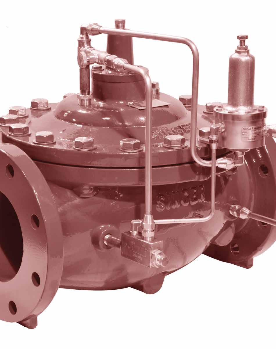
217 Fire Protection
218 Our fire protection valves combine our expert engineering with our never-ending quest for dependable solutions. Solutions that help protect people and property from the ravages of fire. Our commitment to providing solutions for fire protection systems means our range of products continues to grow. For example, our pressure reducing valve automatically reduces a higher inlet pressure to a lower discharge pressure despite changing flows or inlet pressures. Our pressure relief valve automatically relieves excess pressure so the fire protection system doesn t overpressure in response to surges and or pumps turning on or off. Different valves with different functions but both approved for fire safety systems, helping to protect people and property. Singer Valve. Solutions for life-saving applications.


219 Model 106-RPS-8700 UL / FM Pressure Relief Valve Fire Protection KEY FEATURES UL / FM approved for fire extinguishing systems Reliable diaphragm actuated Hydraulically operated design Class 150 and 300 flanges Stainless steel fasteners Heat fused red epoxy coating Available in globe and angle style 106-RPS-8700 Globe Product Overview The 106-RPS-8700 pressure relief valve, which is UL / FM labelled and listed, automatically relieves excess pressure in the fire protection system to discharge. The RPS series valves will also automatically modulate to relieve excess pump capacity during pump start up and shut down, allowing the pump to operate without causing surges. These relief valves are based on the 106-PG or A106-PG main valves and come in complete range of sizes from 2 1/2 in / 65 mm to 8 in / 200 mm. In typical pressure relief application, the angle style A106- RPS-8700 is often the preferred selection. Technical Pressure Rating All valves have 150 lb or 300 lb ANSI flanges and grooved ends. 150 lb flanges related inlet pressure: 200 psi / 13.8 bar / 1,380 kpa 300 lb flanges related inlet pressure: 300 psi / 20.7 bar / 2,070 kpa Grooved ends related inlet pressure: 300 psi / 20.7 bar / 2,070 kp
220 Fire Protection Model 106-RPS-8700 UL / FM Pressure Relief Valve Schematic Drawing 1. Main Valve PG 2. Isolation Valve - lockable (Optional) 3. Strainer - standard 4 in / 100 mm and larger 4. Fixed Restriction- 1/8 in / 3.2 mm 5. Model 852-B Closing Speed Control 6. Model 81-RP pilot - 20 to 200 psi / 1.38 to 13.8 bar - optional 100 to 300 psi / 6.9 to 20.7 bar. 7. Isolation Valve - lockable (Optional) 8. Isolation Valve - lockable (Optional) Schematic A-8700A Standard Materials Standard materials for pilot system components are: ASTM B62 bronze ASTM B16 brass AISI 303 / 316 stainless steel trim Buna-N / EPDM diaphragm and seals Selection Summary 1. Select the valve with sufficient capacity meeting NFPA-20 standards. 2. Usually operating in the momentary m service range (see Technical & Sizing section). 3. Ensure that the maximum inlet pressure rating for the valve and for the flanges exceeds the maximum operating pressure. 4. Select a standard globe style body or the optional angle style body. 106-RPS Flow Capacity 45 ft / s or 14 m / s (See 106-PG in Main Valve Section for other Valve Data) Size (inches) 2-1/2 in 3 in 4 in 6 in 8 in Size (mm) 65 mm 80 mm 100 mm 150 mm 200 mm Momentary (USGPM) Momentary (L/s)
221 Model 106-RPS-8700 UL / FM Pressure Relief Valve Fire Protection Specifications The valve shall be a Singer Valve model UL / FM Labelled 106-RPS-8700, size, ANSI Class 150 (ANSI 300) pressure rating/ flange standard, globe (angle), style valve. The Model 81-RP Pressure Relief Pilot (Normally Closed Pilot) spring range shall be to psi / bar), with setpoint preset at Singer Valve to psi / bar. Assembly shall be according to Schematic A-8700A. The valve shall remain closed until inlet pressure exceeds a pre-determined set-point at which time the valve opens quickly and modulates to limit the upstream pressure to the pre-determined set- point. Prior to shipment, testing shall include UL & FM approved hydrostatic pressure tests and a Singer full function and operation test. Refer to Main Valve section, see page 11, 106-PG for detailed information pertaining to valve sizes, materials and dimensions. Refer to Pilot and Accessories section, page 263, Model 81 Pressure Relief Pilot (Normally Closed Pilot) for detailed information pertaining to materials and specifications. Ordering Instructions Refer to page 293 for the order form and ordering instructions. Additionally, include the following information for this product: Pilot Range


222 Fire Protection Model 106-PR-8702 ULC Pressure Reducing Valve KEY FEATURES ULC approved for fire extinguishing systems Reliable diaphragm actuated Hydraulically operated design Stainless steel fasteners Class 150 and 300 flanges Heat-fused red epoxy coating Available in globe and angle style 106-PR-8702A Globe Product Overview The 106-PR-8702A, which is ULC labelled and listed, is ideal for automatically reducing a higher inlet pressure to a steady lower discharge pressure, regardless of fluctuations in flow or inlet pressure. The valves are based on the 106-PG or A106PG control valves and are available in a complete range of sizes from 1 in / 25 mm to 8 in / 200 mm. In typical pressure reducing applications, the globe style 106-PR-8702A is often the preferred valve style. Technical Pressure Rating 150 lb flanges related working pressure: 175 psi / bar / 1,207 kpa 300 lb flanges related working pressure: 400 psi / 27.6 bar / 2,760 kpa Threaded, NPT related working pressure: 400 psi / 27.6 bar / 2,760 kpa 222
223 Model 106-PR-8702 ULC Pressure Reducing Valve Fire Protection Schematic Drawing 1. Main Valve PG or A106-PG 2. Isolation Valve - standard 4 in / 100 mm and larger 3. Strainer - standard 4 in / 100 mm and larger 4. Model 26 Flow Stabilizer 5. Fixed Restriction 6. Isolation Valve - standard 4 in / 100 mm and larger 7. Model 160 pilot Standard spring: 20 to 200 psi / 1.38 to 13.8 bar; specify for 5 50 psi / bar, psi / bar, psi / bar. 8. Isolation Valve - standard all sizes Schematic A-8702A Standard Materials Standard materials for pilot system components are: ASTM B62 bronze or ASTM B16 brass AISI 303 / 316 stainless steel trim Buna-N / EPDM diaphragm and seals 106-PR-8702 Flow Capacity (See 106-PG in Main Valve section for other valve data) Size (inches) 1 in 1-1/2 in 2 in 2-1/2 in 3 in 4 in 6 in 8 in Size (mm) 25 mm 40 mm 50 mm 65 mm 80 mm 100 mm 150 mm 200 mm Minimum (USGPM) Flat Diaphragm Minimum (L/s) Flat Diaphragm Maximum Continuous (USGPM) Maximum Continuous (L/s)
224 Fire Protection Model 106-PR-8702 ULC Pressure Reducing Valve Selection Summary 1. Select the valve series and size with sufficient capacity as per NFPA-20 standards - see below and / or the performance curves. 2. Check the operating flow against valve minimum. 3. If the outlet pressure is less than 35% of the inlet pressure, consult Singer Valve. 4. Ensure that the rated working pressure of the valve does not exceed the maximum operating pressure. Specifications The valve shall be a Singer Valve model 106-PR-8702A, size, ANSI Class 150 / 300 and NPT pressure rating/ flange standard, globe (angle), style valve. The Model 160 Pressure Reducing Pilot (Normally Open Pilot) spring range shall be to psi / bar, with set point preset at factory to psi / bar. Assembly shall be according to Schematic A-8702A. The valve shall maintain relatively accurate control of the downstream pressure regardless of fluctuation in flow or upstream pressure. Refer to Main Valve section, see page 11, 106-PG, for detailed information pertaining to valve sizes and materials, selection criteria and specifications. Refer to Pilot and Accessories section, page 261, Model 160 Pressure Reducing Pilot (Normally Open Pilot) and Model 26 Flow Stabilizer, page 277, for detailed information pertaining to materials and specifications. Note: Valve must be ULC approved. Ordering Instructions Refer to page 293 for the order form and ordering instructions. Additionally, include the following information for this product: Pilot Range 224
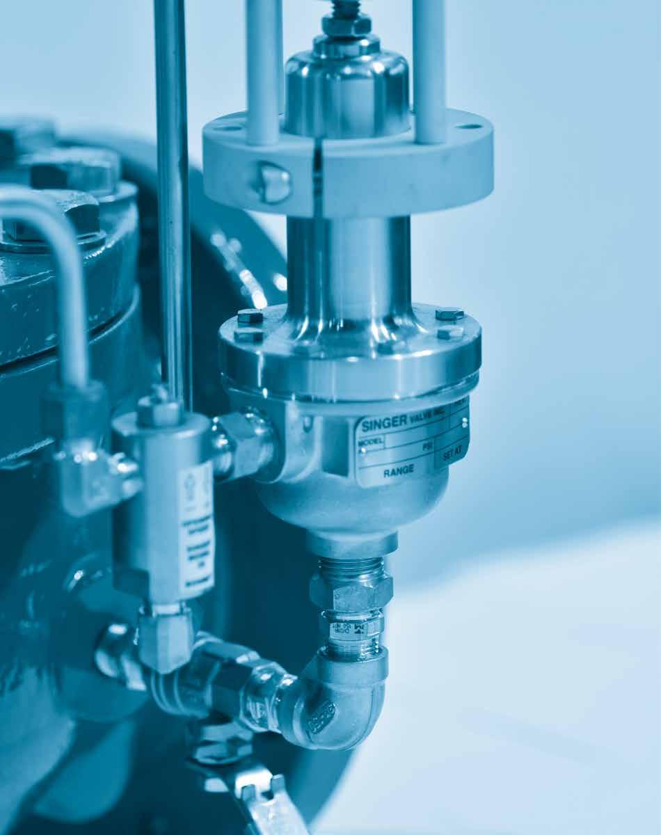
225 Electronic Control
226 The secret of many of our valve solutions lies with their electronic control capability. Whether it s through radio, direct wire connections, cellular networks, satellite or telephone lines, our electronic control management products interface seamlessly and effortlessly with SCADA. Have a single process application? Need to control multiple processes? We customize solutions to meet the demands of unique applications.


.")
.")
227 Models 106-SC / 206-SC Solenoid Control Valve KEY FEATURES Positive, drip-tight shut-off Simple, on-off operation Globe or angle style body Electronics Control 206-SC Globe Product Overview Singer models 106-SC and 206-SC solenoid control valves are based on the Singer model 106-PG or 206-PG main valve. The solenoid pilot valve provides on-off position operation. The solenoid either admits inlet pressure into the main valve operating chamber or releases pressure from the operating chamber. The pilot system is usually piped to discharge at the valve outlet, but can be piped to discharge to drain (atmosphere). The SC valve is available either with the main valve closed when the solenoid is de-energized (NC - Normally Closed) or with the main valve open when the solenoid is de-energized (NO- Normally Open). (NC or NO refers to the main valve, not the solenoid.) Typical Application Tank level control Timer on truck fill station Singer model 106-SC solenoid control valve 227
228 Models 106-SC / 206-SC Solenoid Control Valve Electronics Control Schematic Drawing 1. Main Valve PG or 206-PG 2. Isolating Valves - (2A, 2B, 2C - (optional on 3 in / 80 mm and smaller). 3. Strainer - 40 mesh stainless steel screen 4. Closing Speed Control - model 852-B (optional on 3 in / 80 mm and smaller). 5. Solenoid Pilot Valve 6. Opening Speed Control - model 852-B (optional on 3 in / 80 mm and smaller). SCHEMATIC A-0593C Standard Materials Standard materials for pilot system components are: ASTM B62 bronze or ASTM B-16 brass Stainless steel trim Standard solenoid coil is rated as NEMA 1, 2, 3, 3S, 4 and 4X, combination general purpose and watertight. Other voltages, ratings and constructions are available, consult with Singer Valve. Selection Summary 1. Select the valve with sufficient capacity, using the allowable operating pressure drop across the valve. 2. If the outlet pressure is less than 35% of the inlet pressure, check for cavitation. 3. Ensure the maximum working pressure rating of the valve exceeds the maximum operating pressure. 4. Continuous, C, service up to 20 ft /s / 6 m/s is generally suitable. Refer to chart and/or performance curves (see Technical & Sizing Information section, page 284). 5. Provide system maximum and minimum operating pressures, electrical voltage, etc for correct solenoid selection. 6. If control fluid is from a separate source, provide Singer Valve with details. - For valve positioning - process control, see section 2SC-PCO, Dual Solenoid Control Valve, page For two (2) stage opening or closing, consult with Singer Valve. - Most pilot functions may be combined with the model SC, consult Singer Valve. 228
229 Models 106-SC / 206-SC Solenoid Control Valve 106-SC Flow Capacity (See 106-PG in Main Valve section for other valve data) Size (inches) 1/2 in 3/4 in 1 in 1-1/4 in 1-1/2 in 2 in 2-1/2 in 3 in 4 in Size (mm) 15 mm 19 mm 25 mm 32 mm 40 mm 50 mm 65 mm 75 mm 100 mm Minimum (USGPM) Fflat Diaphragm Minimum (L/s) Flat Diaphragm Maximum Continuous (USGPM) Maximum Continuous (L/s) Electronics Control 106-SC Flow Capacity (See 106-PG in Main Valve section for other valve data) Size (inches) 6 in 8 in 10 in 12 in 14 in 16 in 20 in 24 in 36 in Size (mm) 150 mm 200 mm 250 mm 300 mm 350 mm 400 mm 500 mm 600 mm 900 mm Minimum (USGPM) Flat Diaphragm Minimum (USGPM) Rolling Diaphragm Minimum (L/s) Flat Diaphragm Minimum (L/s) Rolling Diaphragm Maximum Continuous (USGPM) Maximum Continuous (L/s) SC Flow Capacity (See 206-PG in Main Valve section for other valve data) Size (inches) 3 in 4 in 6 in 8 in 10 in 12 in 16 in 18 in 20 in Size (mm) 80 mm 100 mm 150 mm 200 mm 250 mm 300 mm 400 mm 450 mm 500 mm Minimum (USGPM) Flat Diaphrgam Minimum (USGPM) Rolling Diaphrgam Minimum (L/s) Flat Diaphragm Minimum (L/s) Rolling Diaphragm Maximum Continuous (USGPM) Maximum Continuous (L/s) SC Flow Capacity (See 206-PG in Main Valve section for other valve data) Size (inches) 24 x 16 in 24 x 20 in 28 in 30 in 32 in 36 in 40 in Size (mm) 600 x 400 mm 600 x 500 mm 700 mm 750 mm 800 mm 900 mm 1000 mm Minimum (USGPM) Rolling Diaphragm Minimum (L/s) Rolling Diaphragm Maximum Continuous (USGPM) Maximum Continuous (L/s)
230 Models 106-SC / 206-SC Solenoid Control Valve Electronics Control Specifications The valve shall be a Singer Valve model 106-SC / 206-SC, size, ANSI Class 150 (ANSI 300, ANSI Flanges drilled to ISO PN10 / 16 / 25 or 40) pressure rating/ flange standard, globe (angle) style valve. The solenoid pilot shall be ASCO three-way normally closed: de-energize to close valve (normally open: de-energize to open valve) with 120VAC / 60Hz (220VAC / 50Hz or 24VDC) solenoid coil. Assembly shall be according to Schematic A-0593C. The valve shall open and close fully in response to energizing and de-energizing of the solenoid pilot. Refer to Main Valve section, see page 11, 106-PG (or 206-PG) for detailed information pertaining to valve sizes and materials, selection criteria and specifications. Refer to Pilot and Accessories section, see page 279, Model 852-B Needle Valve for detailed information pertaining to materials and specifications of Opening and Closing Speed Controls. Ordering Instructions Refer to page 293 for the order form and ordering instructions. 1 Full port (106) or reduced port (206) 2. Solenoid voltage 3. Energize or de-energize solenoid to close main valve 230

231 Models 106-2SC-PCO / 206-2SC-PCO Dual Solenoid Control for Positioning and SCADA Controls KEY FEATURES Precise control from remote locations Process controller compatible Minimal power needed for stand-by operation Complete service in-line Manual controls for emergencies Electronics Control 206-2SC-PCO Globe Product Overview The Singer models 106-2SC-PCO and 206-2SC-PCO dual solenoid electronic valves are based on the Singer model 106-PG or 206-PG main valve. The flow into and out of the upper operating chamber is controlled by the two pilot solenoids. The electronic control determines whether the opening solenoid or the closing solenoid is operated. The change in valve position is dependent upon which solenoid is operated and the duration of the energized period. The electronic control determines the valve function. Virtually any hydraulic function can be achieved using the open-close output from the SCADA controller to the valve. The Singer Model 2SC-PCO is designed for use with Singer MCP Multi-Process Control Panel or the EPC Single-Process Control Panel

232 Electronics Control Models 106-2SC-PCO / 206-2SC-PCO Dual Solenoid Control for Positioning and SCADA Controls Typical Application The two pilot solenoids are operated to keep two independent signals matched. In this case, the valve is operated to ensure the process variable signal follows the SCADA set-point command signal. Typically this mode is used when the process variable signal is from a flow meter, pressure sensor or similarly quick changing process. This is referred to as set-point control. Singer model EPC controller 4-20 ma SCADA set-point signal Pressure transmitter Singer model 106-2SC-PCO dual solenoid control valve Schematic Drawing 1. Main Valve PG or 206-PG 2. Isolating Valves - (2A, 2B, 2C) 3. Strainer - 40 mesh stainless steel screen 4. Closing Speed Control - micrometer needle valve 5. Closing Solenoid Pilot Valve VAC / 60 Hz standard 6. Opening Solenoid Pilot Valve VAC / 60 Hz standard 7. Manual Closing Bypass 8. Manual Opening Bypass 9. Opening Speed Control - micrometer needle valve 10*. Optional X156 Analog Position Transmitter (4 to 20 ma) INLET *Note*: All 106 series 2 1/2 in / 65 mm to 4 in / 100 mm and all 206 series 4 in / 100 mm to 6 in / 150 mm will be fitted with heavy springs. Schematic A-7637A Note: SRD shown is available for PG and larger. 232
233 Standard Materials Standard materials for pilot system components are: ASTM B-16 brass AISI 316 or 18-8 stainless steel trim NEMA 4X rated solenoid coils Selection Summary Models 106-2SC-PCO / 206-2SC-PCO Dual Solenoid Control for Positioning and SCADA Controls 1. Select a valve with sufficient capacity, using the allowable operating pressure drop across the valve. 2. Usually operating in the continuous, C, service range up to 20 ft /s / 6 m / s - (refer Technical & Sizing Section, page 282). 3. If the outlet pressure is less than 35% of the inlet pressure, check for cavitation. 4. Ensure the max working pressure rating of the valve exceeds the max operating pressure. 5. Ensure the solenoid coils are compatible with the electronic controllers VAC / 60 Hz standard. 6. Verify that the electronic controls are properly configured to provide the functions required. for compatible electronic controls, refer to Singer Process Control Panels, pages 243, 245 for applications requiring high pressure drops, refer to Singer model 106-AC, page 92 standard hydraulic pilots can provide back-up control should the system go off limits for applications where electric service and electronic controls are unsuitable, refer to the standard hydraulic model addition of Position Transmitter and Differential Pressure Transmitter or SPI-MV are required for metering function. Electronics Control 106-2SC-PCO Flow Capacity (See 106-PG in Main Valve section for other valve data) Size (inches) 2-1/2 in 3 in 4 in 6 in 8 in 10 in 12 in 14 in 16 in 20 in 24 in 36 in Size (mm) 65 mm 80 mm 100 mm 150 mm 200 mm 250 mm 300 mm 350 mm 400 mm 500 mm 600 mm 900 mm Minimum (USGPM) Flat Diaphragm CF CF Minimum (USGPM) Rolling Diaphragm Minimum (L/s) Flat Diaphragm CF CF Minimum (L/s) Rolling Diaphragm Maximum Continuous (USGPM) CF CF Maximum Continuous (L/s) CF CF SC-PCO Flow Capacity (See 206-PG in Main Valve section for other valve data) Size (inches) 3 in 4 in 6 in 8 in 10 in 12 in 16 in 18 in 20 in Size (mm) 80 mm 100 mm 150 mm 200 mm 250 mm 300 mm 400 mm 450 mm 500 mm 24 x 16 in 600 x 400 mm 24 x 20 in 600 x 500 mm 28 in 30 in 32 in 36 in 40 in Minimum (USGPM) Flat Diaphragm CF Minimum (USGPM) Rolling Diaphragm Minimum (L/s) Flat Diaphragm CF Minimum (L/s) Rolling Diaphragm Maximum Continuous (USGPM) CF Maximum Continuous (L/s) CF mm 750 mm 800 mm 900 mm 1000 mm Note: CF = Consult Singer Valve on all sizes 3 (80 mm) and under 233
234 Electronics Control Models 106-2SC-PCO / 206-2SC-PCO Dual Solenoid Control for Positioning and SCADA Controls Specification The valve shall be a Singer Valve model 106 (206)-2SC-PCO, size, ANSI Class 150 (ANSI 300, ANSI Flanges drilled to ISO PN10 / 16 / 25 or 40) pressure rating/ flange standard, globe (angle) style valve. Opening and closing solenoid pilots shall be ASCO 2-Way normally closed: energize to open (normally open: energize to close) with 120 VAC / 60 Hz (220 VAC / 50Hz or 24VDC) solenoid coil. Assembly shall be according to Schematic A-7637A. The valve shall be positioned precisely anywhere within its full stroke by operation of the opening and closing solenoid Pilots via Singer Process Control Panel or by customer supplied SCADA system. The valve shall be equipped with manual by-pass to provide emergency override operation. Refer to Main Valve section, see page 11, 106-PG / 206-PG for detailed information pertaining to valve sizes and materials, selection criteria and specifications. Refer to Pilot and Accessories section, see page 279, Needle Valves for detailed information pertaining to materials and specifications of Opening and Closing Speed Controls. Consult Singer Valve for Solenoid specification information. Ordering Instructions Refer to page 293 for the order form and ordering instructions. Additionally, include the following information for this product: 1. Full port (106) or reduced port (206) 2. Inlet / outlet pressure range 3. Solenoid voltage 4. Standard power failure mode is fail at last position specify options a. Fail open on power failure b. Fail close on power failure 234


235 Model 106-( )-SPI-MV Single Point Insertion Flow Metering Valve KEY FEATURES Accurate flow metering, combined with control valve to save space/cost Supplied with Flow Convertor for local display with 4-20mA output measurement or can be combined with PLC-based control panel for flow control applications +/- 2% of rate accuracy, NIST traceable Electronics Control 106-SPI-MV Product Overview The Singer Model 106-SPI-MV is a Single Point Insertion Electromagnetic Flow Meter, installed and calibrated in conjunction with a Singer Valve to provide an accurate flow rate that can be utilized with the metering valve as a stand alone option or built into a 106-2SC-PCO pilot system to provide complete flow-based valve control. The sensor is available for one-inch taps, depending upon valve size and application. The compact insertion design fits in confined spaces and offers complete accessibility. The flow meter can be removed for easy inspection, cleaning, calibrating or verification. This cost effective flow meter option is available for valve sizes from 4 (100mm) to 36 (900mm) inches. The flow sensor comes pre-calibrated from McCrometer s NIST traceable Calibration Lab and requires no recalibration in the field. With no moving parts and a single-piece design, the SPI Mag s sensor contains nothing to wear or break, and it is generally immune to clogging by sand, grit or other debris. The 106-SPI-MV Mag is profiled for the valve body, further enhancing its measurement accuracy by allowing precise determination of mean velocities
236 Model 106-( )-SPI-MV Single Point Insertion Flow Metering Valve Electronics Control Schematic Drawing 1. Main Valve - Model 106-PG 2. Model SPI - Single Point Insertion Meter 3. Local Converter - Flow Indicating Transmitter Note: Local IP67 Converter is standard. Optional enclosures are: Stainless Steel IP66 - NEMA 4 - Panel Mounted (optional) Fibreglass NEMA 4X - Panel Mounted (optional) SS IP66 - NEMA 4X - Panel Mounted (optional) Polycarbonate IP67 NEMA 6 - Panel Mounted (optional) Standard Materials Standard materials for converter enclosures are: IP67 Die cast aluminum - Local SS IP66 - NEMA 4 - Panel Mounted (optional) Fibreglass NEMA 4X - Panel Mounted (optional) Polycarbonate IP67 NEMA 6 - Panel Mounted (optional) Selection Summary 1. Allow 3 pipe diameters minimum upstream of sensor 2. These units can be installed with Singer AC (Anti-Cav) cages 3. Sensor can be installed on either side of valve - inlet only 236
237 Model 106-( )-SPI-MV Single Point Insertion Flow Metering Valve Specifications The valve shall be installed with a 1 (25mm) Single Point Insertion Magnetic Flow Meter in one of the inlet body tappings. Unit will be factory installed and programmed with correlative factors for Main Valve body flow profile. The flow meter shall consist of two components: an electromagnetic sensor and a converter. The 1 (25mm) electromagnetic sensor shall be capable of operating in valves from 4 (100mm) to 36 (900mm). The flow meter shall determine the volumetric flow rate by means of the Continuity Equation where flow rate Q equals mean velocity V times cross sectional area A (Q = V x A). The velocity measurement must be taken at a known location, then, through empirically established equations, the sensed velocity will be converted to a mean velocity. The flow meter converter shall be microprocessor based with a keypad for instrument set up and LCD displays for totalized flow, flow rate engineering units and velocity. The converter shall power the flow-sensing element and provide a galvanically isolated Dual 4-20mA output. It shall be possible, in the test mode; to easily set the converter outputs to any desired value within the range. The 4-20mA scaling, time constants, pipe size, flow proportional output, engineering units and test mode values shall be easily set via the keypad and display. Four separate fully programmable alarm outputs shall be provided to indicate empty pipe, forward/ reverse, polarity (normally open/close), analog over-range, fault conditions, high/low flow rates, percentage of range, and pulse cutoff. The converter shall periodically perform self-diagnostics and display any resulting error messages. All set up data and totalizer values may be protected by a password. The flow-sensing element shall be of an electromagnetic single point type design and factory calibrated to traceable standards, such as NIST. The sensor shall be made of a polyurethane with pure carbon electrodes exposed to flow. To eliminate erroneous readings due to pipe wall effects, the sensor must have its electrodes located at least 3/16 from pipe wall and be designed with a curved tip shape, so as not to collect debris while in the operating position. Flat tipped or Doppler sensors shall not be acceptable. The sensor cable is 20 feet (6m) of multi-conductor, abrasive resistant, PVC jacketed submersible cable flexible to -400F/C. The sensor cable shall be permanently bonded to the sensor. Additional sensor cable, up to 200 feet (61m), shall be available as an option. The insertion tube and restraining rods assembly shall be provided for the smooth installation and operation of the velocity sensor. The stainless steel insertion tube shall be rated for 250 PSI (1, F (710C). Hardware must allow sensor to be secured by bolts when sensor is being inserted and retracted. A stainless steel compression seal assembly shall also be supplied. No flow meters with accuracies expressed as a percentage of full scale will be accepted and flow meter must be NIST Traceable. Electronics Control 237
238 Model 106-( )-SPI-MV Single Point Insertion Flow Metering Valve Electronics Control Ordering Instructions At the time of ordering, please be prepared to provide the following information: Valve size Pressure Minimum flow Fluid Cable length Temperature Flow Capacity 106-SPI-MV (See 106-PG in Main Valve section for other valve data) Size (inches) 4 in 6 in 8 in 10 in 12 in 16 in 20 in 24 in 28 in 36 in Size (mm) 100 mm 150 mm 200 mm 250 mm 300 mm 400 mm Minimum (USGPM) Flat Diaphragm Minimum (USGPM) Rolling Diaphragm Minimum (L/s) Flat Diaphragm Minimum (L/s) Rolling Diaphragm Maximum Continuous (USGPM) 800 1,800 3,100 4,900 7,000 11,000 17,500 25,000 33,600 55,470 Maximum Continuous (L/s) ,104 1,577 2,120 3, mm 600 mm 700 mm 900 mm 238

239 Models 106-2SC-MV / 206-2SC-MV Electronic Flow Control and Metering System 106-2SC-MV Globe KEY FEATURES Combines precise flow control with relatively accurate flow metering, save space / cost PLC-based control panel is compatible with your SCADA system Manual control is available in case of emergencies Re-transmission capabilities Can be field retrofitted to existing valves +/- 3% accuracy, certified by NIST approved testing laboratory (on select sizes) Electronics Control Product Overview The Singer models 106-2SC-MV and 206-2SC-MV electronic flow control and metering valves are based on the 106-PG or 206-PG main valve. The pressure in the upper operating chamber is controlled by operating the pilot solenoids. The PLC within the MV1-TP control panel determines whether the opening solenoid or the closing solenoid is operated. The change in valve position is dependent upon which solenoid is operated and the duration of the energized period. The Singer MV1-TP control panel computes the flow rate based on valve differential pressure and position and operates the pilot solenoids to match the flow rate to the customer s pre-determined (adjustable) set-point. Flow is totalized and displayed via panel readout. In addition, the MV1-TP panel includes a pre-programmed logic controller, touch screen display, labelled wiring and terminal strip

 3.")
240 Models 106-2SC-MV / 206-2SC-MV Electronic Flow Control and Metering System Electronics Control Typical Application Singer model MV1 -TP electronic flow control and metering panel Power supply: 120 VAC / 60 Hz Set-point signal: local or remote To and from SCADA. See available SCADA interface options (page 231) Singer model 106-2SC-MV electronic flow control and metering valve with X156 analog position transmitter, analog differential pressure transmitter, MV1-TP flow limiting and metering panel, dual solenoid control pilot system. Schematic Drawing 1. Main Valve PG or 206-PG 2. Isolating Valves - (2A, 2B, 2C, 2D, 2E) 3. Strainer - 40 mesh stainless steel screen 4. Closing Speed Control 5. Opening Speed Control 6. Closing Solenoid Pilot Valve VAC / 60 Hz standard 7. Opening Solenoid Pilot Valve VAC / 60 Hz standard 8. Model X156 Analog (4-20 ma) Position Transmitter 9. Differential Pressure Transmitter 10. Manual By-Pass Valves - (10A, 10B) - normally closed 11. Model MV1-TP Electronic Flow Control Panel Schematic A-8450C 240
241 Models 106-2SC-MV / 206-2SC-MV Electronic Flow Control and Metering System Standard Materials Standard materials for pilot system components are: ASTM B-16 brass fittings, copper tubing NEMA 4X solenoid coils NEMA panel enclosure Electronics Control Selection Summary 1. Select a valve with sufficient capacity, using the allowable operating pressure drop across the valve. Usually line size. 2. Usually operating in the continuous C, service range up to 20 ft /s / 6 m/s - refer to chart and/or performance curves (see Technical and Sizing Information section, page 282). 3. If the outlet pressure is less than 35% of the inlet pressure, check for cavitation. 4. Ensure the maximum working pressure rating of the valve exceeds the maximum operating pressure. 5. Ensure the solenoid coils are compatible with the electronic controllers VAC / 60 Hz standard. 6. If the operating pressure differential across the valve will exceed 100 psi / 6.9 bar, consult Singer Valve. For applications requiring high pressure drops, refer to Singer model PG-AC (see page 92) 106-2SC-MV Flow Capacity (See 106-PG in Main Valve section for other valve data) Size (inches) 2-1/2 in 3 in 4 in 6 in 8 in 10 in 12 in 14 in 16 in 20 in 24 in 36 in Size (mm) 65 mm 80 mm 100 mm 150 mm 200 mm 250 mm 300 mm 350 mm 400 mm 500 mm 600 mm 900 mm Minimum (USGPM) Flat Diaphragm CF CF Minimum (USGPM) Rolling Diaphragm Minimum (L/s) Flat Diaphragm CF CF Minimum (L/s) Rolling Diaphragm Maximum Continuous (USGPM) CF CF Maximum Continuous (L/s) CF CF SC-MV Flow Capacity (See 206-PG in Main Valve section for other valve data) Size (inches) 3 in 4 in 6 in 8 in 10 in 12 in 16 in 18 in 20 in 24 x 16 in 24 x 20 in 28 in 30 in 32 in 36 in Size (mm) 80 mm 100 mm 150 mm 200 mm 250 mm 300 mm 400 mm 450 mm 500 mm 600 x 400 mm 600 x 500 mm Minimum (USGPM) Flat Diaphragm CF Minimum (USGPM) Rolling Diaphragm Minimum (L/s) Flat Diaphragm CF Minimum (L/s) Rolling Diaphragm Maximum Continuous (USGPM) CF Maximum Continuous (L/s) CF Note: CF = Consult Singer Valve on all sizes 3 (80 mm) and under 700 mm 750 mm 800 mm 900 mm 241
242 Models 106-2SC-MV / 206-2SC-MV Electronic Flow Control and Metering System Electronics Control Specifications The system shall be a Singer Valve model 106-2SC-MV / 206-2SC-MV, size, ANSI Class 150 (ANSI 300, ANSI Flanges drilled to ISO PN10 / 16 / 25 or 40 drillings) pressure rating/ flange standard, globe (angle) style valve. Opening and closing solenoid pilots shall be ASCO 2-Way normally closed: energize to open (normally open: energize to close) with 120VAC / 60Hz (220VAC / 50Hz or 24VDC) solenoid coil. The main valve shall be equipped with Model X mA Position Transmitter and Differential Pressure Transmitter. The Model MV1-TP Flow Control and Metering Panel shall have pre-programmed logic module, adjustments and connection terminals, housed inside NEMA 4X rated raintight enclosure. The system shall relatively accurately measure the flow (via the flow control and metering panel) based on valve position and differential pressure and control the flow by positioning the main valve based on the set-point. The flow control and metering panel shall incorporate a pre-programmed logic controller with P.I.D. optimization and real-math calculation for accuracy. The flow control and metering panel shall have 24VDC, 1.3 Amp auxiliary power supply. Dual solenoid control shall be via solid state relays with zero-voltage switching. The flow control and metering panel shall have door-mounted touch screen interface and display. The valve shall be equipped with manual by-pass to provide emergency override operation. Refer to Main Valve section, see page 11, 106-PG (or 206-PG) for detailed information pertaining to valve sizes and materials, selection criteria and specifications. Refer to Main Valve Options section, see page 88, Model x156 Analog Valve Position Transmitter for information pertaining to material and specifications. Refer to Pilot and Accessories section, page 279, Micrometer Needle Valves for detailed information pertaining to materials and specifications of Opening and Closing Speed Controls. Consult with Singer Valve for Solenoid specification information. Ordering Instructions Refer to page 293 for the order form and ordering instructions. Additionally, include the following information for this product: 1. Full port (106) or reduced port (206) 2. Inlet / outlet pressure range 3. Solenoid voltage 4. Optional NEMA 4x control panel enclosure 242

243 Model EPC Single Process Controller EPC For indoor use only. For outdoor applications, consult factory. KEY FEATURES Simplified loop process controller with advanced P.I.D. implementation Quick configuration for any single process application such as flow and pressure Capable of remote 4 to 20 ma SCADA process set-point adjustment Precise and stable valve positioning IP65 (NEMA 4) front panel sealing, 1/4 DIN package scalable readouts with super bright LCD Capable of local control of model 2SC-PCO dual solenoid valves for single process Electronics Control Product Overview The EPC is a single process loop controller designed to complement the Singer Model 2SC-PCO Dual Solenoid Control Valve. Range of application is dependent on the process variable (feedback) transmitter used, which includes (but not limited to) common automatic control valve functions with conventional pilots. Model EPC controller reads and compares the process feedback (process variable) 4 to 20 ma signal to the desired setting (set-point) 4 to 20 ma signal. Model EPC then accurately positions the valve to bring the process variable towards the set-point until they coincide
 Distribution to users Singer model 106-2SC-PCO / 206-2SC-PCO with X156 valve position transmitter (24 VDC loop powered upon request) Specifications The")
244 Model EPC Single Process Controller Electronics Control Typical Application Maximum water Level Valve 100% closed Level transmitter (power by others) Span Minimum water level valve 100% open Singer EPC controller (SCADA or local controls) Distribution to users Singer model 106-2SC-PCO / 206-2SC-PCO with X156 valve position transmitter (24 VDC loop powered upon request) Specifications The controller shall be a Singer Valve model EPC Controller, powered by 100 VAC to 240 VAC 50 / 60 Hz source. The controller shall come complete with configuration buttons and solid state construction with internal chassis capable of being removed for inspection. The controller shall accept a continuous process variable (feedback) 4-20 ma signal and a continuous set-point (command) 4-20 ma signal. The dual solenoid valve shall be positioned by the controller to bring the process variable towards the set-point. The controller shall have a built-in, adjustable, advanced P.I.D. optimization for accuracy. Deadband, zero, and span of 4-20 ma signal shall be easily adjusted via push buttons. The controller shall have a readout for valve operation. Prior to shipment, the controller shall undergo full function and operational tests. Ordering Instructions Refer to page 293 for the order form and ordering instructions. Additionally, include the following information for this product: 1. Solenoid voltage 2. Source of set-point signal (4-20 ma) 3. Source of process variable signal 4. Optional NEMA 4 enclosure 244

245 Model MCP-TP Multi Process Control Panel Series MCP-TP For indoor use only. For outdoor applications, consult factory. KEY FEATURES Versatility in programming for custom applications Flexibility of single or multiple process monitoring High performance PLC-based control with P.I.D. optimization Capability of remote SCADA 4-20 ma or local set-point(s) adjustment Precise valve positioning Visual status indication Robust and self-contained in NEMA 4X rated panel Intuitive colour touch screen interface display Capable of local control of model 2SC-PCO dual solenoid valves Electronics Control Product Overview The MCP-TP Series is a multiple process loop control panel designed to complement the Singer Model 2SC-PCO Dual Solenoid Control Valve. Range of application is dependent on the feedback (process variables) transmitters used, which is similar to (but not limited to) combination automatic control valve functions with conventional pilots. The MCP-TP control panel has the ability to monitor multiple processes and remotely control the dual solenoid control valve based on system conditions. The MCP-TP control panel can function as a simple single loop controller (e.g., pressure reducing, flow control, level control) to multiple loop controller. The MCP-TP reads transmitted signals and energizes the dual solenoid pilots on the Singer control valve. The MCP-TP can react to any change in conditions by monitoring the system continuously and comparing actual process values to desired set-point values. Optional alarm outputs for SCADA is available

 In-line flow meter with continuous 4 to 20 ma signal transmitter (process variable -")
246 Model MCP-TP Multi Process Control Panel Series Electronics Control Typical Application MCP-TP monitors inlet pressure while filling tank at a relatively steady flow rate. If tank is full, valve closes. If inlet pressure drop below normal, valve will modulate to close to keep inlet pressure from dropping further. Singer MCP-TP - SCADA flow set-point - Local upstream pressure set-point Tank level transmitter 4 to 20 ma (process variable feedback) #3. Water Tower Set-point signal from remote site To and from SCADA (See available SCADA interface options, page 231) In-line flow meter with continuous 4 to 20 ma signal transmitter (process variable - feedback) #1. Power supplied by others 24 VDC. Singer model 106-2SC-PCO / 206-2SC-PCO Upstream pressure 4 to 20 ma signal transmitter (process variable feedback) #2. Touch Panel Model (MCP-TP) touch panel screen is a user-friendly operator interface that enables intuitive control and monitoring. Model (MCP-TP) touch panel screen eliminates the need for mechanical push buttons, switches, and indicator lights and readouts. The screen is custom tailored to customer-specific application requirements. Touch Panel Details Dimensions: 7 in / 175 mm W x 5 in / 125 mm L Display: 256 Color TFT Protection: NEMA 4X rain-tight (indoor use only) Screen can be customized to application 246
247 Model MCP-TP Multi Process Control Panel Series Specifications The multi-process control panel shall be Singer Valve model MCP-TP, powered by 120 VAC to 240 VAC, 50 or 60 Hz source. The Model MCP-TP shall have pre-programmed logic module, adjustments and connection terminals, housed inside NEMA 4X rated rain-tight enclosure. The multi-process control panel shall accept SCADA set-point 4-20 ma signals and process variable 4-20 ma signals. The dual solenoid control valve shall be positioned by the multi-process control panel based on specified system conditions. The multi-process control panel shall incorporate a pre-programmed logic controller with P.I.D. optimization and real math calculation for accuracy. The multi-process control panel shall have 24 VDC, 1.3 amp auxiliary power supply. Dual solenoid control shall be via solid state relays with zero-voltage switching. The multi-process control panel shall have a door-mounted color touch screen interface. Prior to shipment, the panel shall undergo full function and operational tests. Electronics Control Ordering Instructions Refer to page 293 for the order form and ordering instructions. Additionally, include the following information for this product: 1. Application details 2. Solenoid voltage 3. Source of set-point signal (4-20 ma) 4. Source of process variable signal(s) 5. Number of processes to be controlled 247

248 SAP Panel for Model RPS-L&H-ET Surge Anticipator Panel Electronics Control KEY FEATURES Automatically interfaces pressure switch and control valve to protect system from destructive pressure surges Visual indication of operational status Simple to install Minimizes field wiring costs RPS-L&H-ET For indoor use only. For outdoor applications, consult factory. Product Overview The SAP surge anticipator panel provides the interface between a customer supplied, system pressure switch and the Singer surge anticipating control valve. Together they provide protection against destructive pressure surges. The SAP panel energizes the control valve pilot solenoid on an abnormally low pressure reading and/or power failure to pumps. The 12 VDC pilot solenoid is energized to open the main valve and relieve the surge pressure from the system. The RPS-L&H-ET (ET- Electronically Timed) valve is equipped with a hydraulic pilot to relieve on abnormally high pressures. The SAP panel is equipped with adjustable digital delay timers that permit coordination of valve operation with pump start-ups, shutdowns, power failures and down surges. The SAP panel comes equipped with a long life, high capacity 12 VDC battery, industrial grade battery charger with over current and polarity protection, door mounted volt meter and battery test feature. The logical arrangement of indicator lights and the volt meter provide easy supervision of the sequencing and the operating status. 248
 3. Strainer - 40 mesh, J0097A 4.")
249 SAP Panel for Model RPS-L&H-ET Surge Anticipator Panel Typical Application Singer Valve Surge Anticipator Panel Model SAP as shown Pressure Switch Singer Valve 106-BPC Pump Control valve Electronics Control RPS-L&H-ET Valve 120 VAC / 60 Hz Power Supply Solenoid Schematic Drawing Schematic A-7606C 1. Main Valve / 206-PG 2. Isolating Valve (2A, 2B, 2C) 3. Strainer - 40 mesh, J0097A 4. Fixed Restriction - 3/32 in / 2.4 mm 5. Closing Speed Control B 6. Pressure Switch - supplied by others 7. Manual Test Valve - 3-way ball valve with lockable handle 8. Solenoid Valve - 12 VDC Normally Closed 9. Model 81-RP, Relief Pilot 10. Swing Check Valve - 1/2 in / 15 mm 11. Limit Switch Assembly - optional 12. Connection to Header 13. Connection to Header by others 14. Pressure Gauge 1/4 in / 6 mm NPT Note: Singer Surge Anticipator Control Panel - not shown in schematic but shown in above typical application 249
250 SAP Panel for Model RPS-L&H-ET Surge Anticipator Panel Electronics Control Specifications The surge anticipator panel shall be a Singer Valve model SAP, powered by selectable 120 VAC / 60 Hz source and complete with un-interruptible 12 VDC battery back-up and charger. Logic module, relays, battery and charger shall be housed inside a NEMA 4 rated rain tight enclosure. Logic module, relays, and fully labelled connection terminals shall be housed inside a NEMA 4 rated rain tight enclosure. The surge anticipator panel shall open the electronic surge anticipator valve for a predetermined time after pump power failure or pressure down surge, in anticipation of a returning surge wave. The surge anticipator panel shall accept a pressure switch dry contact and auxiliary pump motor starter dry contact for proper interface with the pumping system. Three adjustable digital timers shall be provided: Start-up timer, surge anticipator timer, and shut-down timer. The surge anticipator panel shall use a pre-programmed logic module to provide proper sequencing and digitally adjustable delay timer adjustments. A system test button shall simulate surge condition and open the valve. Prior to shipment, the panel shall undergo full function and operational tests. Ordering Instructions Refer to page 293 for the order form and ordering instructions. Additionally, include the following information for this product: Optional pressure switch 250

251 Model SPC Pump Control Panel SPC KEY FEATURES Automatically interfaces pump and control valve to avoid starting and stopping surges Visual indication of operational status Simple to install Suitable for use with either in-line booster or deep well by-pass pump control valves Reduces field wiring costs For indoor use only. For outdoor applications, consult factory. Electronics Control Product Overview The SPC pump control panel provides the interface between the pump motor starter and the Singer pump control valve. The SPC ensures that the pump starts and stops without causing line surges. The SPC panel energizes the control valve pilot solenoid simultaneously with pump start. When pump shut-down is required the panel keeps the pump running while the pilot solenoid is de-energized. The panel turns the pump off just as the control valve completes its full stroke travel. The SPC panel is equipped with delay timers and emergency fault contacts to provide the customer with local and remote indication for various operational failure conditions. The SPC panel is connected to the pilot solenoid and limit switch that are standard components in the control valve pilot system. The panel is also connected to the customer supplied pump discharge pressure switch and the pump motor starter. A second limit switch and emergency shutdown solenoid are optional components for the control valve pilot system. The logical arrangement of indicator lights with the Hand Off Automatic (HOA) selector switch provides easy supervision of the sequencing and the operating status

252 Model SPC Pump Control Panel Electronics Control Typical Application Singer Pump Control Panel Model SPC-EC-LS as shown Pump Motor Starter Pump Start Contacts Limit Switch Solenoid 120 VAC / 60 Hz Power Supply Note: Wiring done by others Selection Summary 1. Equipped with Singer Valve programmed logic module, the Singer Model SPC can be readily customized to meet client s requirements. The two most common configurations are: SPC-IDC-2LS For PTC based Singer pump control valves with internal drop check and dual limit switches. Typically used for non-modulating applications where the valves are required to open fully. SPC-EC-LS For PG based Singer pump control valves with modulating functions, no internal drop check, and equipped with emergency closing solenoids. Specifications The pump control panel shall be a Singer Valve model SPC- -, powered by 120 VAC / 60 Hz (220 VAC / 50 Hz) source, suitable for interfacing with Singer Model 106-BPC, -PG-BPC and -DW / 206-BPC, PG-BPC and DW pump control valves. The panel shall include 3 amp controls circuit breaker, and a 20 amp motor starter panel contact circuit breaker. Logic module, relays, and fully labelled connection terminals shall be housed inside a NEMA 4X rated rain tight enclosure. 252
253 Model SPC Pump Control Panel The pump control panel shall provide proper sequencing and operation of the pump control valve with the pumping system. The pump control panel shall accept a pressure switch dry contact, limit switch dry contact, and remote start command contact The pump control panel shall use a pre-programmed logic module to provide proper sequencing and digitally adjustable delay timer adjustments The pump control panel shall have cover-mounted HOA (Hand Off Automatic) switch, operation indicator lights, and alarm indicator lights Prior to shipment, the panel shall undergo full function and operational tests Electronics Control Ordering Instructions Refer to page 293 for the order form and ordering instructions. Additionally, include the following information for this product: 1. Solenoid voltage 2. SPC-IDC-2LS or SPC-EC-LS configuration 253

254 Model 420-DC / 420-AC Automated Pilot Control Electronics Control Valve actuator 24 VDC power 4-20 ma input 1 rpm Coupling Clamp 4 in / 100 mm Shown with 160 Pressure Reducing Pilot (not included) 420-dc 12 5/8 in / 320 mm KEY FEATURES Temporarily submersible IP67 enclosure IP68 connector available as an option Quick troubleshooting Predictable, repeatable accuracy Easily adjustable set-point and range Long-life using slow speed actuator Valve mounting saves space and cost Suitable for all valve sizes Downstream pressure follows the control signal within +/ psi / bar May be fitted in the field to most sizes and makes of automatic control valves Position feedback potentiometer 0-5K ohms Programmable span and speed via optional cable and software Product Overview The 420-DC or 420-AC provide for a reliable, simple and cost efficient way to automate today s water systems. When a sturdy slow speed 24 VDC motor actuator drive is fitted onto the 160-PR pilot, this pilot then becomes the DC. The minimum system pressure downstream of the pressure reducing valve is set by adjusting the pilot screw that compresses the pilot spring. The motor actuator responds to a 4-20 ma signal, rotating the pilot adjusting screw corresponding to the change in signal. The number of turns is adjustable and may be programmed to suit the pressure change per turn of the pilot screw to produce the desired maximum and minimum downstream pressure. The DC or AC requires less than 1 amp power to operate, controlled by the 4-20 ma signal from the water distribution SCADA system. The very low power requirement lends itself well to a solar powered self contained station. Extended power failure would result in relatively steady pressure at the last setting. Optional freeze or default to high or low pressure available on loss of signal. 254
255 Model 420-DC / 420-AC Automated Pilot Control Note: The AC version ( AC) supplied with AC to DC power supply (not shown). The Model 420-DC or 420-AC is also available as the 160-RF-420-DC or 160-RF-420-AC (used with the 160-RF Pilot on the RF-Rate of Flow control valve), or as the 81-RP-420-DC or 81-RP-420-AC (used with the 81-RP Pilot on the RPS-Pressure Relief /Pressure Sustaining control valve). Contact Singer Valve for further details. Electronics Control Typical Application In the case of a DC or AC with downstream base pressure of 60 psi / 4.1 bar the desired range is psi / bar adjustable by remote signal. Select / bar spring range. Adjust pilot screw to 60 psi / 4.1 bar setting. Fit actuator (1 turn adjusts pressure approximately 20 psi / 1.38 bar). Using laptop and simple program provided, adjust turns so that 4 ma = 60 psi / 4.1 bar and 20 ma = 80 psi / 5.5 bar. Time for full range equals one minute. Accuracy within +/ psi pressure for given ma signal. Specifications The pilot shall be a Singer Model DC or AC pilot. The DC or AC responds to customers 4-20 ma signal to adjust the downstream pressure within the range psi to psi. The actuator operates at 1 RPM and will adjust the pressure at the rate depending on the spring range selected. Pilot spring ranges: Standard psi / bar; Optional 2-20 psi / bar, 2-50 psi / bar, psi / bar, psi / bar In addition to the standard 106-PR / 206-PR valve specifications, replace the 160 pilot as above. Consult Singer Valve for specifications for the 160-RF-420-DC or 160-RF-420-AC and/or the 81-RP- 420-DC or 81-RP-420-AC. Ordering Instructions Refer to page 293 for the order form and ordering instructions. Additionally, include the following information for this product: 1. Application (Singer Valve Model #) 2. Pilot utilized 3. Pilot spring range 4. Required adjustable operating pressure range 255
256
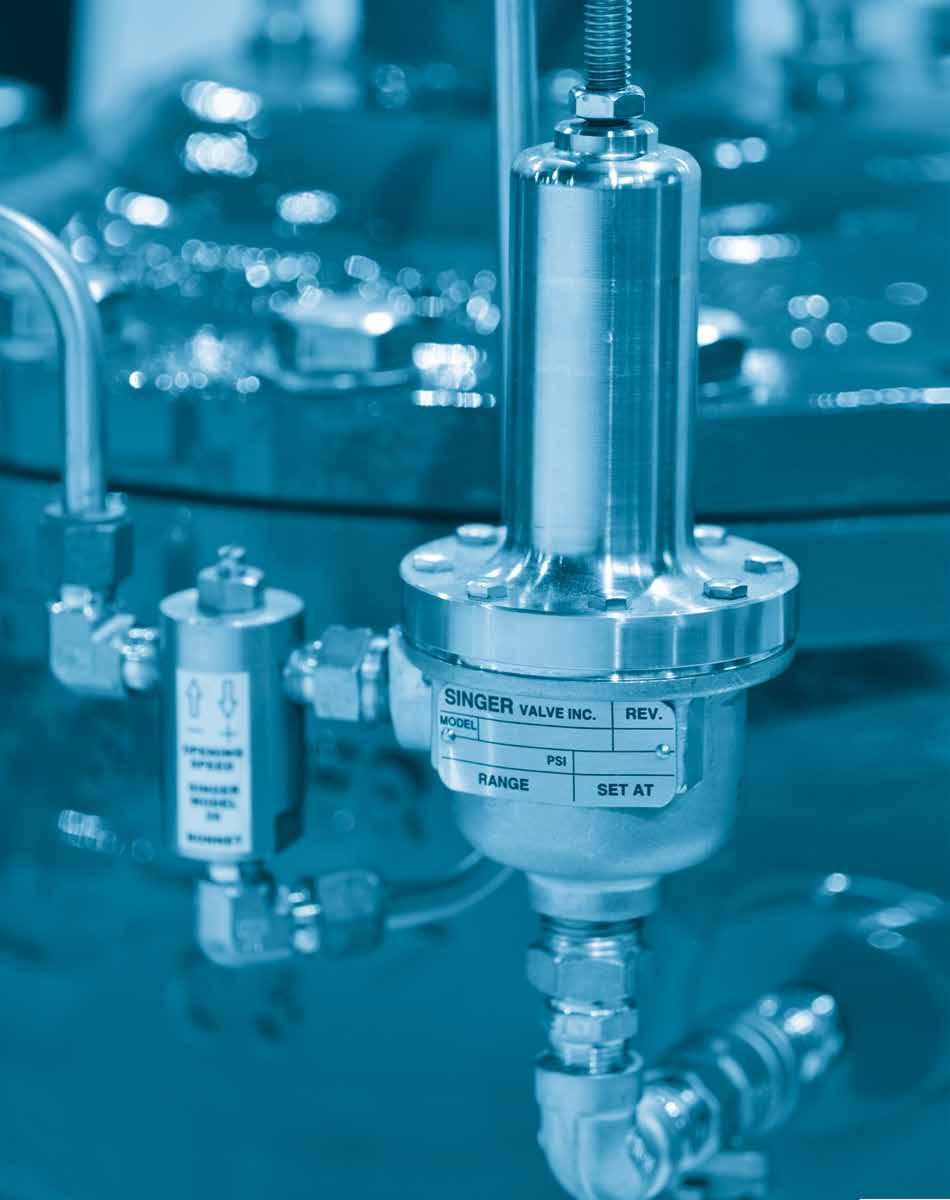
257 Pilots and Accessories
258 Customize. Accessorize. Specialize. At Singer Valve, our pilots and accessories offer you options and choices. Like customizing a Singer float valve with our rotary float pilot or adding a Singer internal drop check assembly to a main valve for quick, positive shut-off when normal forward flow stops. To resist corrosion, you can upgrade components to stainless steel or to prevent mineral build-up and premature valve failure, you can choose our flexible stainless steel braided hose. Pilots. Needles. Tubing. Strainers. Options we design. Accessories you specify. Oxy-Nitride Stem Main Valve Option Prevents build-up. Resists corrosion. Reduces maintenance. Our proprietary oxy-nitride treated 316 stainless steel stem is ideal when mineral build-up on stems may cause maintenance problems or operational malfunctions. The stem is treated in an aerated salt bath so it reduces or prevents mineral build-up, allowing the stem to stroke freely as it passes through the guide bushing. Ideal for: reclaimed water applications Pressure Reducing Pilot PR-160 Self-cleaning. Self-flushing. Non-clogging. This normally open pilot is spring and diaphragm operated. It has a non-clogging pilot guide stem above the diaphragm, which is removed from the flow of water in the main pilot chamber. Because the outlet is located in the bottom of the pilot, 90 degrees to the inlet, the pilot is self-cleaning and self-flushing, thereby eliminating debris build-up. It also minimizes turbulence and false readings. This is the standard pressure reducing pilot for all our pressure reducing valves. Ideal for: regulating water pressure

259 Model ZS Strainer KEY FEATURES 316 Stainless Steel, large area Z plate screen Ductile iron, fusion-bonded, epoxy-coated construction Complies with AWWA C701 & C702 Standard Materials Body: ASTM A536-65/45/12 ductile iron, fusion bonded, epoxy coated Cover: 045 Steel, fusion bonded, epoxy coated Seal: Buna-N Screen: 316 Stainless Steel Drain Plug: 316 Stainless Steel Pilots & Accessories Product Overview The Singer Model ZS Strainer is designed to protect control valves and pipelines from foreign matter and debris in the flow stream. The Z plate screen design is excellent for providing a smooth laminar flow, which is ideal for locations ahead of automatic control valves. The Z plate screen is manufactured in corrosion resistant Stainless Steel and allows for a large flow area. It is easily removed by taking off the top cover plate. It is also supplied with flushing ports on both sides of the strainer along with an air bleed connection and connections across the screen for the installation of a differential pressure gauge if required. Product Line Drawing 1/4" NPT SINGER 1/2" NPT 1/4" NPT Top View Front View Side View Dimensions in inches 150 lb. / 300 lb. Flanged A DIM B DIA Flange OD D DIM NPT Drain Screen 150 lb. 300 lb. 150 lb. 300 lb. 150 lb. 300 lb. E DIM Plugs Perforation Size Flanged Flanged Flanged Flanged Flanged Flanged Confirm availability and delivery of all sizes with factory
260 Model ZS Strainer Dimensions in millimetres PN10/ PN16 / PN25 Flanged Pilots & Accessories A DIM B DIA Flange OD D DIM NPT Drain Screen PN10 / PN16 PN 25 PN10 / PN16 PN 25 PN10 / PN16 PN 25 E DIM Plugs Perforation Size Flanged Flanged Flanged Flanged Flanged Flanged 80 mm mm mm mm Confirm availability and delivery of all sizes with factory. Specifications The strainer shall be a Singer Model ZS, ANSI Class 150 (ANSI 300, ANSI Flanges drilled to PN 10/16/ 25 or 40) pressure rating/flange standard. The strainer body shall be constructed of ASTM A536-65/45/12 ductile iron or equivalent. The cover shall be constructed of 1045 Steel or equivalent. The strainer shall have a protective fusion bonded coating externally and internally that shall conform to ANSI/AWWA C116/A21.16 (current version) specification. No matching of external parts after final coating will be acceptable to ensure continuous coating surface throughout the entire strainer. Strainer screen shall be a 316 Stainless Steel Z plate, drilled/punched with holes to give greater than the pipe area to minimize head loss. It shall be removable through the top cover without the need for any special tools. Flat or curved screen will not be acceptable. All external fasteners shall be AISI 18-8 Stainless Steel with AISI 18-8 Stainless Steel washers. Mild steel studs or bolts will not be acceptable. Drain ports and connection tappings will be supplied with 316 stainless steel plugs. Ordering Instructions Please use the following code when you order this product: Strainer Size Material Flanges ZS- 003 D A Size Code Material Code End Connections Code Ductile Iron D ANSI 150# A ANSI 300# B ISO PN16 K ISO PN25 L 80 mm mm mm mm 200 Examples: ZS-003DA = ZS Strainer 3-150# ZS-080DK = ZS Strainer 80 mm-iso PN16 260
261 Model 160 Pressure Reducing Pilot (Normally Open) 9 (230 mm) Max. INLET 3/8 NPT SCHEMATIC A0708D OUTLET 3/8 NPT 3 (80 mm) Adjusting Screw (Stainless Steel) 2. Locknut (Stainless Steel) 3. Spring Step (Stainless Steel) 4. Spring (Steel) 5. Spring Casing Stem (Bronze) 6. Stem (Stainless Steel) 7. Guide Bushing (Delrin) 8. Retaining Ring (Stainless Steel) 9. Clamp Plate Seal (Brass) 10. Diaphragm (EPDM) 11. Clamp Plate (Brass) 12. Yoke (Stainless Steel) 13. Seat Ring Seal (Buna-N) 14. Seat Ring (Stainless Steel) 15. Inner Valve (Stainless Steel and EPDM) 16. Body (Bronze) 17. Outlet Connector (Brass) Options: Available in all Stainless Steel construction. Viton or Buna-N Elastomers Pilots & Accessories Product Overview The 160 Pressure Reducing Pilot is a spring and diaphragm operated, normally open pilot. The inner valve is held open by the spring and when the control pressure below the diaphragm exceeds the force of the spring, the pilot valve closes. Model 160 is the standard pressure reducing pilot on all 106 and 206 series valves. Specifications The pilot shall be Singer Model 160, with the spring range specified. The normally open pilot shall be of bronze construction with a spring to adjust the pressure setting. The pilot seat, stem, yoke and inner valve shall be of stainless steel 316 construction and the inner valve shall have EPDM resilient compound for seating. The EPDM compound must be bonded permanently to the inner valve and be ground flat and square to assure maximum performance. The pilot stem shall be guided by a Delrin bushing in the spring casing above the diaphragm and totally removed from the flow of water in the main pilot chamber. The pilot guide and stem location above the diaphragm shall eliminate debris buildup and sticking as well as minimize turbulence and false readings on the diaphragm. The pilot shall be self-cleaning and self-flushing by locating the outlet in the bottom of the pilot ninety degrees to the inlet. Maximum working temperature: 180 F / 82 C Maximum working pressure: 400 psi / 27.6 bar Spring Ranges Approximate psi per turn Standard 20 to 200 psi (1.38 to 13.8 bar) 30 psi (2 bar) per turn 5 to 50 psi (0.345 to 3.45 bar) 9 psi (0.62 bar) per turn Optional 10 to 80 psi (0.7 to 5.5 bar) 14 psi (0.96 bar) per turn Ordering Instructions Refer to page 293 for the order form and ordering instructions. 100 to 300 psi (6.9 to 20.7 bar) 42 psi (2.9 bar) per turn 261
262 Model 160 RF Rate of Flow Pilot (Normally Open) Pilots & Accessories SENSING PORT 1/4 NPT INLET 3/8 NPT **21 SCHEMATIC A0709E OUTLET 3/8 NPT *Recommended Spare Parts - supplied in Parts KIT **Range 2-20 psid only Max. 1. Body (Bronze) *2. Diaphragm (EPDM) 4. Stem (Stainless Steel) *5. Inner Valve (Stainless Steel & EPDM) 6. Yoke (Silicon Bronze) 7. Clamp Plate (Brass) 8. Spring Casing (Bronze) 9. Retaining Ring (Stainless Steel) 10. Guide Bushing (DELRIN) 11, 16, 17. Fasteners (Stainless Steel) *12, 19. Seal (Buna-N) 13, 21. Spring (Spring Steel) 14, 20. Spring Step (Stainless Steel) 15. Thread Seal (Steel & Buna-N) 18. Seat Ring (Stainless Steel) **21. Bucking Spring (Stainless Steel) **22. Bleed Screw (Stainless Steel) **23. Bleed Screw Seal (Stainless Steel and Neoprene) Product Overview The 160-RF pilot is a spring and diaphragm operated pilot designed to sense a differential across an external orifice plate. It is a normally open pilot that also has a sensing port is in the spring casing, above the diaphragm and is available in stainless steel. The inner valve is held open by the spring and when the control pressure below the diaphragm exceeds the combined forces of the spring and the sensing pressure, the pilot valve closes. The 160-RF is the standard rate of flow control pilot on all 106 and 206 series valves. Specifications The normally open pilot shall be of bronze construction with a spring to adjust the pressure setting and as a result, flow rate. The pilot seat, stem, yoke and inner valve shall be of stainless steel 316 construction and the inner valve shall have EPDM resilient compound for seating. The EPDM compound must adhere safely to the inner valve and be ground flat and square to assure maximum performance. The pilot stem shall be guided by a Delrin bushing in the spring casing above the diaphragm and totally remove from the flow of water in the main pilot chamber. The pilot guide and stem location above the diaphragm shall eliminate debris build-up and sticking as well as minimize turbulence and false readings on the diaphragm. The pilot shall be self-cleaning and self-flushing by locating the outlet in the bottom of the pilot ninety degrees to the inlet. A sensing port shall be provided in the spring casing above the diaphragm. Maximum working temperature: 180 F / 82 C Maximum working pressure: 400 psi / 27.6 bar Spring Ranges Approximate psi per turn Standard 2 to 20 psi (0.138 to 1.38 bar) 2 psi (0.138 bar) per turn Optional 5 to 50 psi (0.345 to 3.45 bar) 4 psi (0.27 bar) per turn Ordering Instructions Refer to page 293 for the order form and ordering instructions. 262
263 Model 81-RP Pressure Relief Pilot (Normally Closed) 7 (175 MM) Max. SENSING 1/4 NPT INLET 3/8 NPT SCHEMATIC A0661C 15 Options: All Stainless Steel construction. Viton or Buna-N Elastomers OUTLET 3/8 NPT Adjusting Screw (Stainless Steel) 2. Lock Nut (Stainless Steel) 3. Spring Casing (Bronze) 4. Upper Spring Step (Stainless Steel) 5. Spring (Steel) 6. Lower Spring Step (Stainless Steel) 7. Stem Locknut (Stainless Steel) 8. Clamp Plate Seal (Buna-N) 9. Clamp Plate (Brass) 10. Diaphragm (EPDM) 11. Body Seal (Buna-N) 12. Inner Valve (Stainless Steel and EPDM) 13. Body (Brass) 14. Seat Ring Seal (Buna-N) 15. Seat (Stainless Steel) Pilots & Accessories Product Overview The 81-RP is a remote sensing, high capacity, spring and diaphragm operated, normally closed pilot. The inner valve is held closed by the spring. When the sensed pressure increases above the spring setting, the pilot opens. Model 81-RP pilot is used as the standard pressure relief/sustaining pilot on all 106 and 206 series valves. Specifications The pilot shall be Singer Model 81-RP, with the spring range specified. The normally closed pilot shall be of brass and bronze construction with a spring to adjust the opening pressure. The inner valve shall be of stainless steel 316 construction and the inner valve shall have EPDM resilient compound for seating. The EPDM compound must be bonded permanently to the inner valve and be ground flat and square to assure maximum performance. The pilot shall be self-cleaning by locating the inlet directly into the seat area through the bottom of the pilot and the outlet ninety degrees to the inlet. A separate port will sense pressure either upstream or downstream (subject to application) to open the pilot and therefore the main valve when system pressure exceeds the pilot set-point. Maximum working temperature: 180 F / 82 C Maximum working pressure: 400 psi / 27.6 bar Spring Ranges Approximate psi per turn Standard 20 to 200 psi (1.38 to 13.8 bar) 25 psi (1.7 bar) per turn 5 to 50 psi (0.345 to 3.45 bar) 9 psi (0.62 bar) per turn Optional 10 to 80 psi (0.7 to 5.5 bar) 14 psi (0.96 bar) per turn 100 to 300 psi (6.9 to 20.7 bar) 42 psi (2.9 bar) per turn Ordering Instructions Refer to page 293 for the order form and ordering instructions
264 Model 83-RP High Pressure Relief Pilot (Normally Closed) Pilots & Accessories 7 (175mm) Max. 10 1/4 NPT INLET 3/8 NPT 1 2 3A 4 3B OUTLET 3/8 NPT 9 1. Adjusting Screw (Stainless Steel) 2. Spring Casing (Brass) 3. Spring Steps (3A, 3B) (Stainless Steel) 4. Spring (Steel) 5. Diaphragm (EPDM) 6. Clamp Plates (Brass) 7. Inner Valve ((Stainless Steel and EPDM) 8. Body (Brass) 9. Seat (Stainless Steel) 10. O Ring Seals (Buna-N) Options: Available in all Stainless Steel construction. SCHEMATIC A0781A 3 (80mm) Product Overview The 83-RP is a spring and diaphragm operated, normally closed pilot specifically designed for high pressure applications. The inner valve is held closed by the spring. When the control sensed pressure below the diaphragm exceeds the force of the spring, the pilot valve opens. Model 83-RP pilot is used as the standard pressure relief pilot where the operating pressures are excessive, such as a 300 psi / 20.7 bar level. Specifications The pilot shall be Singer Model 83-RP, with the spring range specified. The normally closed pilot shall be of brass and bronze construction with a spring to adjust the opening pressure. The inner valve shall be of stainless steel 316 construction and the inner valve shall have EPDM resilient compound for seating. The EPDM compound must be bonded permanently to the inner valve and be ground flat and square to assure maximum performance. The pilot shall be self-cleaning by locating the inlet directly into the seat area through the bottom of the pilot and the outlet ninety degrees to the inlet. A separate port will sense pressure either upstream or downstream (subject to application) to open the pilot and therefore the main valve when system pressure exceeds the pilot set-point. Maximum working temperature: 180 F / 82 C Maximum working pressure: 600 psi / 41.4 bar Spring Ranges Approximate psi per turn Standard 200 to 500 psi (13.8 to 34.5 bar) 80 psi (5.5 bar) per turn Ordering Instructions Refer to page 293 for the order form and ordering instructions. 264
265 Model 81-RPD Differential Pressure Relief Pilot (Normally Closed) 7 (175mm) Max. SCHEMATIC A0662C SENSING 1/4 NPT INLET 3/8 NPT 3 (80mm) OUTLET 3/8 NPT 1. Adjusting Screw (Stainless Steel) 2. Lock Nut (Stainless Steel) 3. Thread Seal (Steel and Buna-N) 4. Spring Casing (Brass) 5. Spring Step (Stainless Steel) 6. Spring (Stainless Steel) 7. Stem Lock Nut (Stainless Steel) 8. Spring Casing Capscrew (Stainless Steel) 9. Diaphragm (EPDM) 10. Clamp Plate (Brass) 11. Clamp Plate Seal (Buna-N) 12. Stem Seal (Buna-N) 13. Inner Valve (Stainless Steel and EPDM) 14. Seat Ring Seal (Buna-N) 15. Body (Brass) 16. Seal (Stainless Steel) Pilots & Accessories Options: Available in all Stainless Steel construction. Product Overview The 81-RPD is a remote sensing, high capacity, spring and diaphragm operated, normally closed, differential pilot. The inner valve is held closed by the spring. When the pressure under the diaphragm overcomes the combined forces of the spring setting and the pressure above the diaphragm, the pilot opens. The 81-RPD valve is used for remote sensing of a differential pressure for normally closed applications. Specifications The pilot shall be Singer Model 81-RPD, with the spring range specified. The normally closed pilot shall be of brass and bronze construction with a spring to adjust the opening pressure differential. The inner valve shall be of stainless steel 316 construction and the inner valve shall have EPDM resilient compound for seating. The EPDM compound must be permanently bonded to the inner valve and be ground flat and square to assure maximum performance. The pilot shall be self-cleaning by locating the inlet directly into the seat area through the bottom of the pilot and the outlet ninety degrees to the inlet. Two separate ports (one above and one below the diaphragm), will sense a pressure differential allowing pilot and therefore the main valve to modulate subject to pressure differential, maintaining a relatively steady set-point. Maximum working temperature: 180 F / 82 C Maximum working pressure: 400 psi / 27.6 bar Spring Ranges Approximate psi per turn Standard 20 to 200 psi (1.38 to 13.8 bar) 30 psi (2 bar) per turn 5 to 25 psi (0.345 to 1.72 bar) 3 psi (0.2 bar) per turn Optional 10 to 80 psi (0.7 to 5.5 bar) 10 psi (0.7 bar) per turn 100 to 350 psi (6.9 to 24 bar) 41 psi (2.82 bar) per turn Ordering Instructions Refer to page 293 for the order form and ordering instructions
266 Model Altitude Pilot Valve Pilots & Accessories 27-3/8 (695 mm) Sensing Connection to Reservoir 1/4 NPT Exhaust to Drain EX 1/4 NPT EX Upstream Supply Connection X 3/8 NPT Connection to Bonnet K port 3/4 NPT Stem (Stainless Steel) 2. Spring (Steel) 3. Diaphragm Casing (Ductile Iron) 4. Diaphragm (Buna-N) 5. Inner Valve (Stainless Steel and EPDM) 6. Body (Stainless Steel) Standard Materials: Other standard material of the pilot construction include brass, aluminum, stainless steel, Buna-N SCHEMATIC A0847A 15-5/8 (395 mm) Product Overview An altitude pilot valve is spring and diaphragm operated; it controls the water level in a reservoir by sensing the hydrostatic head. When the hydrostatic head equals the spring force, the pilot connects port X (connection to main valve inlet ) to port K (connection to main valve bonnet). The main valve closes. When the hydrostatic pressure decreases slightly, the port X to K connection is closed by the inner valve. When the hydrostatic pressure is reduced even further, the pilot connects port K (main valve bonnet) to EX (exhaust to atmosphere). Then the main valve opens. Model pilot is used as the standard pilot on all 106 and 206 series altitude valves. Specifications The pilot shall be Singer model with the spring range specified. The pilot shall consist of a ductile iron housing and shall have a protective fusion bonded coating, which conforms to the ANSI / AWWA C116 / A21.16 (current version) specification. The 3-way valve body, seat and stem shall be of stainless steel construction. The inner valve shall have EPDM resilient compound for seating. The EPDM compound must be permanently bonded to the inner valve and be ground flat and square to assure maximum performance. The pilot shall utilize a rolling diaphragm stem seal to eliminate friction when the pilot actuates. The 3-way valve body shall be serviceable without removing the pilot from the valve. The inner valve shall be replaceable Approximate fixed differential Model Spring Range / Elevation Delayed opening Approximate feet per turn to 20 ft (1 to 6 m) 1 ft (0.3 m) 1 ft (0.3 m) per turn to 60 ft (3 to 18 m) 1 ft (0.3 m) 2 ft (0.6 m) per turn to 125 ft (12 to 38 m) 2 ft (0.6 m) 3 ft (0.9 m) per turn to 225 ft (18 to 69 m) 3 ft (0.9 m) 6 ft (1.8 m) per turn Ordering Instructions Refer to page 293 for the order form and ordering instructions. 266
267 Model R-400 Modulating Float Pilot 3/8 NPT Inlet /2 (445mm) 3-1/8 (80mm) 1-3/16 (30mm) float 5 (127mm) Diameter pilot closed Modulation range 9 pilot 1. Body (Bronze) 2. Inner Valve (Buna-N) 3. 3 / 8 in NPT Outlet 4. Stem (Brass) 5. Lever (Brass) 6. Serrated Arm (Brass) 7. Float Rod (Brass) 8. Lock Nut (Stainless Steel) 9. Float (Polypropylene) Options: Copper float; Stainless Steel Rod. Pilots & Accessories fully open SCHEMATIC A0714D Product Overview The R-400 is a modulating float pilot with a plastic float, suitable for remote installation on a tank or reservoir. It positions the main valve in proportion to the reservoir level. Standard configuration is for the pilot to close on rising level. Specify Reverse Acting for the pilot to open on rising level. The polypropylene float connects to the pilot on a 10 in / 250 mm brass rod. The R-400 pilot is used as the standard float pilot on all 106 and 206 series modulating float valves. Specifications The pilot shall be a Singer Model R-400. The pilot shall be of the modulating style and made of brass and bronze construction. The inner valve shall utilize Buna-N seals to provide drip-tight shut-off in the valve body. The pilot shall include a 10 in / 250 mm brass float rod and a polypropylene float. The brass float rod shall pivot from the lever located on pilot. The pilot shall be self-cleaning and self-flushing by locating the outlet in the bottom of the pilot ninety degrees to the inlet. The pilot will close the valve on rising water level however the pilot will modulate between open and closed in direct proportion to reservoir level. Maximum working temperature: 120 F / 49 C Maximum working pressure: 80 psi / 5.5 bar Ordering Instructions Refer to page 293 for the order form and ordering instructions
268 Model 34 Modulating Float Pilot with Vertical Rod Pilots & Accessories 13 (330mm) 1 INLET 1/ /16 (106mm) /16 (261mm) OUTLET 1/ Body (Bronze) 2. Inner Valve (Stainless Steel) 3. Valve Stem (Stainless Steel) 4. Connector Bar (Brass) 5. Mounting Bracket (Brass) 6. Counter Weight (Cast Iron) 7. Guide Bar (Brass) 8. Float Rod (Brass) 9. Lever Arm (Brass) Options: Available with stainless steel float and rod Note: When ordered as a part and/or when shipping via air freight, the 1/4 in / 6.35 mm)diameter x 4 ft / 1.2 m round brass rod is not included. float 7 (175mm) SCHEMATIC A0606B Product Overview The 34 modulating float pilot is comprised of a copper float and brass rod assembly which moves vertically. As the level rises, the float lifts and the valve closes. The 34 pilot is optional pilot, available for modulating applications where the float and rod are installed in a still well and / or vertical action is preferred. Specifications The pilot shall be a Singer model 34. The pilot shall be of the modulating style and made of bronze and brass construction. The pilot shall include a 4 ft / 1.2 m brass float rod and a copper float. The brass float rod shall have a vertical stoke controlled by a lever arm and counter weight. The pilot will close the valve on rising water level however the pilot will modulate between open and closed in direct proportion to reservoir level. Maximum working temperature: 120 F / 49 C Maximum working pressure: 80 psi / 5.5 bar Ordering Instructions Refer to page 293 for the order form and ordering instructions. 268
269 Model 35 Modulating Float Pilot 1. Body (Stainless Steel AISI 303) 2. Cam (Stainless Steel AISI 303) 3. Inner valve (Stainless Steel AISI 303) 4. Locknut (2) (Stainless Steel 18-8) 5. Stop pin (Stainless Steel AISI 302) 6. Pivot pin (Stainless Steel AISI 302) 7. Float rod (Stainless Steel AISI 303) 8. Float (Stainless Steel 18-8) Pilots & Accessories SCHEMATIC A0797B Product Overview Model 35 is a Stainless Steel modulating float pilot with a Stainless Steel float, suitable for remote installation on a tank or reservoir. It positions the main valve in proportion to the Reservoir level. Standard configuration is for the pilot to close on rising level. Specify Reverse Acting for the pilot to open on rising level. The Stainless Steel float connects to the pilot using a 10 in / 250 mm Stainless Steel rod. Specifications The pilot shall be a Singer Model 35. The pilot shall be of the modulating style and of Stainless Steel construction. The pilot will close the valve on rising water level and will modulate the main valve in proportion to the reservoir level. Maximum Working Temperature: 120 F / 50 C Maximum Working Pressure: 232 psi / 16 bar Ordering Instructions Refer to page 293 for the order form and ordering instructions
270 Model 39 Non-Modulating Float Pilot with Vertical Rod Pilots & Accessories 10 (250mm) (125mm) in in : inlet to upstream boss of main valve b : to bonnet of main valve x : exhaust to drain x 10.5 (270mm) b 7 (178mm) Diameter 8 1. Body (Brass) 2. Inner Valve O-rings (Buna-N) 3. Inner Valve (Brass) 4. Connector Bar 5. Mounting Bracket (Brass) 6. Guide Bar (Brass) 7. Counter Weight (Cast Iron - Epoxy Coating) 8. Float Rod (Brass) 9. Lever Arm (Brass) 10. Adjustable Stop (Brass) 11. Float (Copper) 12. Adjustable Stop Opening (Brass) Options: Available in Stainless Steel construction. SCHEMATIC A0411A 12 Product Overview The 39 non-modulating float pilot is designed to operate an On-Off float valve. The differential between the level where the valve opens and the level where the valve closes, is adjustable. The standard configuration is for the pilot valve to close on high level and open at a low level. The 39 pilot is used as the standard pilot on all non-modulating F-Type 5, 106 and 206 series float valves. Specifications The pilot shall be a Singer model 39. The pilot shall be non-modulating and made of brass and stainless steel construction. The pilot shall include a 4 ft / 1.2 m brass float rod with adjustable stops and a copper float. (alternate lengths of float rod are available) The pilot will close the main valve on rising water level. Maximum working temperature: 180 F / 82 C Maximum working pressure: 80 psi / 5.5 bar Ordering Instructions Refer to page 293 for the order form and ordering instructions. 270
 3 4 Standard Materials: SST pilot, inner valve, copper float, 4 ft / 1.2 m brass rod.")
271 Model 43 Rotary Float Pilot (On/Off) Mounting Bracket (Brass) 2. Counter Weight (Stainless Steel) 3. Float Rod (Brass) 4. Float (Copper) 3 4 Standard Materials: SST pilot, inner valve, copper float, 4 ft / 1.2 m brass rod. Pilots & Accessories Model 43 Detail 43 Product Overview The 43 stainless steel float actuated pilot with non-modulating rotary motion, provides non-modulating On-Off operation of the main valve. It has higher capacity and faster response time than other nonmodulating float pilots. The differential between the level where the main valve opens and the level where the main valve closes, is adjustable. The 43 pilot allows for faster operation of the main valve over traditional float pilots, due to increased port size. The standard configuration is for the pilot to close the main valve on high level and open the main valve on low level. The 43 pilot is used on all non-modulating model F-Type 5, 106 and 206 series float valves. The 43 pilot has a higher pressure rating 150 psi / bar as compared to Model 39 (80 psi / 5.5 bar). Specifications The pilot shall be a Singer Model 43. The pilot shall be non-modulating and made of 316 stainless steel construction. The inner valve shall utilize Buna-N seals to provide drip-tight shut-off in the valve body. The pilot shall include a 4 ft / 1.2 m brass float rod with adjustable stops and a copper float (alternate lengths of float rod are available). The pilot shall close the main valve on rising water level (standard configuration). Maximum working temperature: 180 F / 82 C Maximum working pressure: 150 psi / bar C v flow coefficient is 0.21 Can be utilized as part of sump ejector assembly 271
272 Model 43 Rotary Float Pilot (On/Off) Schematic Drawing BACK FRONT 3.13 (80mm) 2.38 (60mm) Pilots & Accessories X IN BODY IN: Connect to upstream boss of main valve B: Connect to bonnet of main valve X: Exhaust to drain B (124mm) (178mm) SCHEMATIC A0986A 1. Mounting Bracket (Brass) 2. Main Lever Arm (Brass) 3. Counterweight (Stainless Steel) 4. Counterweight Rod (Stainless Steel) 5. Lower Lever Arm (Brass) 6. Space Bar (Brass) 7. Float Rod (Brass) 8. Adjustable Stop (Brass) 9. Inner Valve (Teflon) 10. Casing (Stainless Steel) 11. Stem (Stainless Steel) 12. Wave Spring Washer (Stainless Steel) 13. Body (Stainless Steel) 14. Lock Nut (Stainless Steel) Ordering Instructions Refer to page 293 for the order form and ordering instructions. 272
273 Model 106-RD Differential Relief Pilot (Normally Closed) Adjusting Screw (Stainless Steel) 2. Locknut (Stainless Steel) 3. Thread Seal (Stainless Steel & Buna-N) 4. Spring Step (Brass) 5. Spring (Stainless Steel) 6. Spring Casing (Brass) 7. Spring Casing Screws (Stainless Steel) 8. Spring Cup (Brass) 9. Diaphragm (EPDM) 10. Body (Brass) Pilots & Accessories 9 10 SCHEMATIC A0556B Product Overview The model 106-RD is a spring and diaphragm operated, normally closed pilot designed to allow flow when the inlet pressure exceeds the outlet pressure by a predetermined amount. The model 106-RD is used as a differential control valve on Singer model 106-A-Type 4 altitude control valves. Specifications Maximum Working Temperature: 120 F / 82 C Maximum Working Pressure: 400 psi / 27.5 bar Spring Ranges: 5 to 15 ft / 2 to 7 psi; 1.5 to 4.6 m / 0.14 to 0.48 bar 10 to 50 ft / 4 to 22 psi; 3 to 15.2 m / 0.28 to 1.52 bar Ordering Instructions Refer to page 293 for the order form and ordering instructions
274 Model 625-RPD Differential Pilot (Normally Closed) Pilots & Accessories Flow Adjusting Screw (Stainless Steel) 2. Locknut (Stainless Steel) 3. Thread Seal (Steel & Buna-N) 4. Spring Step (Brass) 5. Spring (Stainless Steel) 6. Clamp Plate Nut (Stainless Steel) 7. Clamp Plates (Brass) 8. Diaphragm Flange (Ductile Iron) 9. Bonnet (Brass) 10. Body (Bronze) 11. Seat Ring (Stainless Steel) 12. Bottom Cap (Brass) 13. Spring Casing (Ductile Iron) Standard Materials: Other standard material of the pilot construction include stainless steel, Buna-N, and brass X - RPD High Pressure Sensing Connection - 1/4 in NPT Y - RPD Low Pressure Sensing Connection - 1/4 in NPT SCHEMATIC A0312C Product Overview The model 625-RPD is a remote sensing, spring and diaphragm operated, normally closed pilot with large diaphragm area for increased sensitivity. The pilot opens when the control pressure exceeds the spring force or the differential established by the spring. The model 625 is used for special applications where a low pressure set point or highly sensitive and responsive pilot is required. Specifications Maximum Working Temperature: 180 F / 82 C maximum Maximum Working Pressure: 400 psi / 27.6 bar Spring Ranges: 5 to 15 ft / 1.5 to 4.6 m; 12 to 30 ft / 3.7 to 9.1 m; 25 to 50 ft / 7.6 to 15.2 m Ordering Instructions Refer to page 293 for the order form and ordering instructions. 274
275 Model 82-PR Pilot (Normally Open) (200 mm) 1. Adjusting Screw (Stainless Steel) 2. Locknut (Stainless Steel) 3. Spring Step (Brass) 4. Spring Casing (Brass) 5. Spring (Stainless Steel) 6. Stem Locknut (Stainless Steel) 7. Diaphragm (EPDM) 8. Body (Brass) 9. Bottom Cap (Brass) 10. Disc Retainer (Stainless) 11. Resilient Disc (Buna-N) 12. Inner Valve (Stainless Steel) 13. Spring Casing Screws (Stainless Steel) 14. Clamp Plate (Brass) 15. O-Ring Seals (Buna-N) Pilots & Accessories Standard Materials: Other standard material of the pilot construction include stainless steel, Buna-N, and brass SCHEMATIC A0667C Product Overview The model 82-PR is a spring and diaphragm operated, normally open pilot valve, with the sensing chamber(s) separated from the operating chambers. It closes when the control pressure below the diaphragm exceeds the force of the spring. The model 82-PR is used as the standard low pressure pilot on model RPS-L&H anticipating surge valves. Specifications Maximum Working Temperature: 180 F / 82 C Maximum Working Pressure: 400 psi / 27 bar Spring Ranges: Standard: 20 to 80 psi / 1.4 to 5.5 bar Optional: 7 to 50 psi / 0.48 to 1.7 bar, 45 to 200 psi / 3.1 to 13.8 bar, 100 to 350 psi / 6.9 to 24.1 bar, 200 to 500 psi / 13.8 to 34.5 bar Ordering Instructions Refer to page 293 for the order form and ordering instructions


276 Stainless Steel Hose Stainless Steel Braided Hose Copper Standard material for tubing Corrosion resistant Reliable and long-term performance Pilots & Accessories Stainless Steel Optional upgrade Significantly stronger and more durable Corrosion and oxidation resistant Stainless Steel Braided Hose Optional upgrade Completely flexible Significantly stronger and more durable Corrosion and oxidation resistant Size Working Pressure Lengths Connection Type Copper Standard 1/4 in / 6 mm 3/8 in / 9.5 mm 1/2 in / 12.7 mm 3/4 in / 19 mm 1/4 in: 1,406 psi / 96.9 bar 3/8 in: 984 psi / 67.8 bar 1/2 in: 727 psi / 50.1 bar 3/4 in: 511 psi / 35.2 bar Any Flared Stainless Steel Optional Upgrade 1/4 in / 6 mm 3/8 in / 9.5 mm 1/2 in / 12.7 mm 3/4 in / 19 mm 1/4 in: 21,000 psi / 1,447.3 bar 3/8 in: 14,000 psi / bar 1/2 in: 10,500 psi / bar 3/4 in: 7,000 psi / bar Any Compression Braided Hose Optional Upgrade 1/4 in / 6 mm 3/8 in / 9.5 mm 1/2 in / 12.7 mm 3/4 in / 19 mm 1/4 in: 3,000 psi / bar 3/8 in: 2,500 psi / bar 1/2 in: 2,000 psi / bar 3/4 in: 1,500 psi / bar Any SAE Ordering Instructions Refer to page 293 for the order form and ordering instructions. Additionally, include the following information for this product: Material(s) 276
277 Model 26 Flow Stabilizer Product Overview Label as shown on Model Standard Materials: Body: AISI 303 SST Spring Retainer: ASTM B16 Brass Locknut: ASTM B16 Brass Adjusting Screw: AISI 303 SST Inner Valve: AISI 303 SST Spring: AISI 303 SST Screw Seal: Buna-N The 26 Flow Stabilizer is a self-cleaning, opening speed control. It is used in conjunction with a fixed restriction orifice that is usually threaded into port 3. The 26 stabilizer allows free flow down to the bonnet (port 1) and restricts flow up from port 1. The 26 stabilizer is used as the standard flow stabilizer (opening speed control) on model 106-PR or 206-PR pressure reducing valves or any other model that requires low flow stabilization. Pilots & Accessories Product Line Drawing 1. Adjusting Screw 2. Locknut 3. Screw Seal 4. Body 5. Inner Valve 6. Spring 7. Spring Retainer PORT 3 3/8 (9.5mm) 2 (50mm) PORT Specifications The flow stabilizer shall be a Singer model 26. The flow stabilizer body shall be of stainless steel construction. The flow stabilizer shall allow unrestricted flow into the main valve bonnet while offering adjustable restricted flow out of the bonnet. The flow stabilizer shall be self cleaning and resistant to plugging The Singer proprietary tapered internal orifice and inner valve shall offer precise adjustment, which shall be lockable by utilizing the top locknut. The flow stabilizer shall improve low flow stability when incorporated with other Singer Low Flow proprietary automatic control valve enhancements Maximum Working Temperature: 180 F / 82 C Maximum Working Pressure: 400 psi / 27.6 bar Connections: 1/4 in (no metric equivalent) NPT Ordering Instructions Refer to page 293 for the order form and ordering instructions /4 (32mm) PORT
278 Fixed Restriction Sizes: A 1 / 8 in / 3.2 mm orifice B 1 / 16 in / 1.6 mm orifice C 3 / 32 in / 2.4 mm orifice Pilots & Accessories D 1 / 4 in / 6.35 mm orifice E 7 / 64 in / 2.8 mm orifice Product Overview The fixed restriction is a 303 stainless steel bodied fitting with a stainless steel orifice plug. The fixed restriction controls the flow rate in the pilot system. The orifices are sized to provide the proper control to a select series of valve sizes only. This allstainless steel version replaces all previous versions of the brass body, with stainless steel insert. Sizes: A 1/8 in / 3.18 mm orifice B 1/16 in / 1.59 mm orifice C 3 / 32 in / 2.38 mm orifice D 1/4 in / 6.35 mm orifice E 7 / 64 in / 2.8 mm orifice Specifications Maximum working temperature: 180 F / 82 C Maximum working pressure: 600 psi / 41.4 bar Connections: 1/4 in (no metric equivalent) NPT Ordering Instructions Refer to page 293 for the order form and ordering instructions. 278


279 Speed Control / Needle Valves Flow Control Valves / Pilot Check Valves Model 852-B Needle Valve Speed Control The 852-B needle valve is a pilot speed control valve. The body is brass and the stem is stainless steel with a fine thread for controlling flow. O ring packing assures leak proof, trouble free service. 1/4 in / 6.35 mm NPT female to female end connections. Specifications Maximum operating temperature: 180 F / 82 C Maximum working pressure: 400 psi / 27.6 bar Model J0074A Micrometer Needle Valves Micrometer needle valves allow for precise speed control. There is virtually infinite flow adjustment in both directions. Standard end connections are female-to-female 1/4 in / 6.35 mm NPT. Standard Materials Forged brass body, Buna-N seals and stainless steel stem Specifications Maximum fluid temperature: 180 F / 82 C Maximum pressure rating: 2000 psi / 138 bar Pilots & Accessories Model J0053A Micrometer Flow Control Valves Micrometer flow control valves allow for precise flow control. There is full flow in one direction and adjustable restricted flow in the opposite direction. They are standard on certain models, such as BPC pump control valves and available as an option for other applications. Standard end connections are female-to-female 1/4 in / 6.35 mm NPT. Standard Materials Forged brass body Urethane disc Stainless steel stem Stainless Retaining Ring Buna-N seals Specifications Maximum fluid temperature: 140 F / 60 C Maximum pressure rating: 2000 psi / 138 bar Model 10 &12 Pilot Check Valves The 10 pilot check valve is standard on all 106 and 206 series valves requiring a pilot check function such as BPC, PR-C, RPS-C types. It is designed to require a low cracking differential pressure to open. The 12 has a higher cracking pressure and requires more differential pressure to open. Standard Materials: Body: ASTM B16 brass Seat Ring: ASTM B-16 brass Inner Valve: Lexan Seals: Buna-N Specifications: Maximum working temperature: 180 F / 82 C Maximum working pressure: 400 psi / 27.6 bar 279
280 Models J0098A & J0097A Strainers Pilots & Accessories Model J0097A Standard Materials: Body: Stainless Steel 316 Screen Retainer: Stainless Steel 316 Screen (40 Mesh): Stainless Steel 316 Screen Retainer Seal: Buna Blow Down Plug: Stainless Steel 316 Product Overview There are two versions of the standard AISI 316 stainless steel strainer with 40 mesh stainless steel screens. The standard strainer J0098A has a 3/8 in / 9.5 mm blowdown/maintenance port for access to the screen and the 3/8 in / 10 mm NPT inlet and outlet connections. The J0097A strainer provides a standard 1/4 in / 6.35 mm sensing / gauge connection. Specifications The strainer shall be a Singer Model J0098A or J0097A (additional 1/4 in / 6.35 mm connection). The strainer body shall be of 316 stainless steel construction. The strainer shall be mounted externally on the main valve for easy access and internal screen shall be easily removed and cleaned. The strainer shall have the outlet located ninety degrees to the inlet. The body shall have a 3/8 in / 10 mm NPT plug for easy access and / or installation of an optional ball valve for easy screen flushing. The Model J0097A shall be complete with an additional unfiltered 1/4 in / 6.35 mm NPT sensing or gauge connection. Maximum working temperature: 180 F / 82 C Maximum working pressure: 400 psi / 27.6 bar Ordering Instructions Refer to page 293 for the order form and ordering instructions. 280
 Optional - brass Nuts: Brass Drain Valve: Brass Pilots & Accessories Product Overview The Arion series strainers are more suited to dirty water applications.")

 valve 2. Discharge Tube 3. Double Mesh 18-8 Stainless Steel Screens 4. A 1/2 in NPT Inlet and Outlet Connections 5. Low Velocity Settling Zone 6.")
281 Models J1521G & J1521M Arion Strainers J1521M Standard Materials: Body: Brass Cap: Brass Screens: 18-8 SST (40 mesh optional; 80 mesh optional) Seals: Buna-N Packing: P.T.F.E. Bowls: Standard - Trogamid T (Glass) Optional - brass Nuts: Brass Drain Valve: Brass Pilots & Accessories Product Overview The Arion series strainers are more suited to dirty water applications. The dirt is trapped on the inside of the double mesh screens and collects in the bowl. The double port construction of the housing prevents the particles from re-entering the flow stream. The collected dirt can be flushed directly out to drain by opening the blowdown. The J1521G strainer has a glass collection bowl, while the J1521M strainer has a metal bowl. Standard pressure rating for the strainer is 232 psi / 16 bar. Body connections are 1/2 in / 15 mm NPT and it comes complete with a 3/8 in / 9.5 mm blowdown valve and a discharge tube. Product Line Drawing 1. Blowdown (drain) valve 2. Discharge Tube 3. Double Mesh 18-8 Stainless Steel Screens 4. A 1/2 in NPT Inlet and Outlet Connections 5. Low Velocity Settling Zone 6. 1/4 in NPT Gauge Connections 7. Double Neck, Housing Directs Particles Onwards 8. Collection Bowl - Glass (Optional Brass) Specifications Maximum working temperature: Glass: 104 F / 40 C Metal: 208 F / 80 C Maximum working pressure: Glass and Metal: 232 psi / 16 bar Ordering Instructions Refer to page 293 for the order form and ordering instructions. Additionally, include the following information for this product: Metal or glass bowl May be included as standard with some products 12 in (300 mm) 2.5 in (65 mm)
MODEL 106-PT / 106-PTC / S106-PT / S106-PTC DOUBLE CHAMBER HYDRAULICALLY OPERATED VALVE
 MAIN VALVES MODEL 06-PT / 06-PTC / S06-PT / S06-PTC KEY FEATURES Maintains positive control under all operating pressures Precise positioning Internal drop check option included on the PTC model Available
The Ideal Solution for Protecting People and Property From the Ravages of Fire. SingerValve.com
 FIRE PROTECTION The Ideal Solution for Protecting People and Property From the Ravages of Fire. SingerValve.com TABLE OF CONTENTS About Singer The Singer Advantage... 3 Main Fire Valves 106-RPS-8700A Pressure
SINGER VALVE CONDENSED PRODUCT CATALOGUE INDUSTRIAL
 SINGER VALVE CONDENSED PRODUCT CATALOGUE INDUSTRIAL Effective Solutions for Industrial Water Management. singervalve.com Performance You Can Trust At Singer Valve, we care about performance. That s why
Automatic Control Valves. Protecting people and property from the ravages of fire
 Automatic Control Valves Protecting people and property from the ravages of fire Contents 02 The Mueller Advantage 03-05 Pressure Relief Valves 06-07 Pressure Reducing Valve 08 Modulating Float Valve 09-10
KEY FEATURES. Product Overview. Product Line Drawing
 Main Valves Options Model 106-C 106-PG-C Globe KEY FETURES Solves high pressure drop problems Controls variable flows & vibration Significantly reduces noise Self-contained actuators not required Customizable
ALTITUDE CONTROL VALVES FOR ONE WAY FLOW
 PROJECT NAME LOCATION ALTITUDE CONTROL VALVES FOR ONE WAY FLOW INTRODUCTION This specification covers the design, manufacture, and testing of 2 in. (50 mm) through 36 in. (900 mm) Control Valves PART 1
PRESSURE RELIEF / SURGE ANTICIPATOR CONTROL VALVE
 PROJECT NAME LOCATION PRESSURE RELIEF / SURGE ANTICIPATOR CONTROL VALVE INTRODUCTION This specification covers the design, manufacture, and testing of 2-1/2 in. (65 mm) through 18 in. (450 mm) Control
PRESSURE RELIEF / SUSTAINING CONTROL VALVES
 PROJECT NAME LOCATION PRESSURE RELIEF / SUSTAINING CONTROL VALVES INTRODUCTION This specification covers the design, manufacture, and testing of 1 in. (25 mm) through 36 in. (900 mm) Control Valves PART
PRESSURE REDUCING CONTROL VALVES
 PROJECT NAME LOCATION PRESSURE REDUCING CONTROL VALVES INTRODUCTION This specification covers the design, manufacture, and testing of 1 in. (25 mm) through 36 in. (900 mm) Control Valves PART 1 - GENERAL
MODEL 106/206-PG POWER OPERATED GLOBE VALVE Sizes 1/2" to 8" (106-PG) 3" to 10" (206-PG) Installation, Operating and Maintenance Instructions
 3 to 10 (206-PG) Installation, Operating and Maintenance Instructions") MODEL 106/206-PG POWER OPERATED GLOBE VALVE Sizes 1/2" to 8" (106-PG) 3" to 10" (206-PG) Installation, Operating and Maintenance Instructions DESCRIPTION: This valve is the basic component used for most
MODEL 106/206-PG POWER OPERATED GLOBE VALVE Sizes 1/2" to 8" (106-PG) 3" to 10" (206-PG) Installation, Operating and Maintenance Instructions DESCRIPTION: This valve is the basic component used for most
COMBINATION PRESSURE REDUCING AND SOLENOID SHUTOFF CONTROL VALVES 2.01 COMBINATION RESSURE REDUCING AND SOLENOID SHUTOFF CONTROL VALVE
 PROJECT NAME LOCATION COMBINATION PRESSURE REDUCING AND SOLENOID SHUTOFF CONTROL VALVES INTRODUCTION This specification covers the design, manufacture, and testing of 1 in. (25 mm) through 36 in. (900
FLOAT CONTROL VALVES
 PROJECT NAME LOCATION FLOAT CONTROL VALVES INTRODUCTION This specification covers the design, manufacture, and testing of 8 in. (200 mm) through 36 in. (900 mm) Control Valves PART 1 - GENERAL 1. Standard
MODULATING FLOAT CONTROL VALVE
 PROJECT NAME LOCATION MODULATING FLOAT CONTROL VALVE INTRODUCTION This specification covers the design, manufacture, and testing of 2 in. (50 mm) through 36 in. (900 mm) Control Valves PART 1 - GENERAL
SOLENOID CONTROL VALVE
 PROJECT NAME LOCATION SOLENOID CONTROL VALVE INTRODUCTION This specification covers the design, manufacture, and testing of 4 in. (100 mm) through 36 in. (900 mm) Control Valves PART 1 - GENERAL 1. Standard
Level Alert Model Multi-Switch Liquid Level Sensor. Assembly and Installation Instructions
 Level Alert Model 2000 Multi-Switch Liquid Level Sensor Assembly and Installation Instructions Kit Form Each unit is provided in kit form with step-by-step instructions, making it extremely easy to custom
HYDRAULIC CONTROL VALVES
 HYDRAULIC CONTROL VALVES The automatic control valves are diaphragm valves designed to provide hydraulically driven solutions to pressure, flow and level control applications. Features: Main valve uses
Series 500 Valves. Product Catalogue. Series 500 Valves. Series 500 Valves. Catalogue. Edition 10/2012
 Series 500 Valves Product Catalogue Catalogue Areas Of Activity Waterworks Dorot s valves are especially designed to comply with all the demands of Waterworks systems such as Pressure Management, Low Flow
BERMAD Waterworks. Booster Pump Control Valve Active Check Valve. 700 Series. Model 740. Features and Benefits. Major Additional Features
 Booster Pump Control Valve Active Check Valve Isolates system from the effects of pump starts and stops for: Solitary single speed pumps Battery of single speed pumps (add & switch) Battery of variable
SECTION ELECTRONIC ACTUATED PRESSURE REDUCING VALVES AND ACCESSORIES
 SECTION 33 12 16.05 REDUCING VALVES AND ACCESSORIES PART 1 - GENERAL 1.1 THE REQUIREMENT A. The Electronic Actuated Pressure Reducing Valve (PRV) shall maintain a constant downstream pressure regardless
BERMAD Waterworks. Pressure Relief/Sustaining Valve. Model: WW Series. Features and Benefits. Major Additional Features
 Pressure Relief/Sustaining Valve Prioritizing pressure zones Ensuring controlled pipeline fill-up Preventing pipeline emptying Pump overload & cavitation protection Safeguarding pump minimum flow Excessive
PRESSURE REDUCING CONTROL VALVE
 PRESSURE REDUCING CONTROL VALVE 06/08 Schematics Throttles to reduce high upstream pressure to constant lower downstream pressure Reducing setpoint is adjustable 2 (AOS) X P/L Standard Components 1 Main
PRESSURE REDUCING VALVE
 Schematic Throttles to reduce high upstream pressure to constant lower downstream pressure Low Flow By-Pass controls at low flows 4 PRESSURE REDUCING VALVE with LOW-FLOW BY-PASS FEATURE Main Line valve
DOROT CONTROL VALVES CATALOGUE
 DOROT CONTROL VALVES CATALOGUE Content SERIES 80 Globe & Angle Irrigation Valves 4 SERIES 80 80-1, 80-3/4 Turf Irrigation Valves 6 SERIES 75 Gal Plastic Valves 8 SERIES 95/96 UPVC Valves 10 Plastic Control
Mustang Series PRESSURE REDUCING CONTROL VALVE. M115 (Globe) M1115 (Angle) Schematic. Standard Components. Options & Accessories.
 M1115 (Angle) Schematic. Standard Components. Options & Accessories.") PRESSURE REDUCING CONTROL VALVE 02/09 Schematic Throttles to reduce high upstream pressure to constant lower downstream pressure Reducing setpoint is adjustable 2 (AOS) P/L Standard Components 1 Main Valve
PRESSURE REDUCING CONTROL VALVE 02/09 Schematic Throttles to reduce high upstream pressure to constant lower downstream pressure Reducing setpoint is adjustable 2 (AOS) P/L Standard Components 1 Main Valve
SERIES 2100 Resilient Seated Butterfly Valves
 SERIES 2100 Resilient Seated Butterfly Valves Publication S2100-101 Issue 06/16 Rev. C Design Characteristics Applications Commercial Heating & Air Conditioning Waste Water & Water Treatment Sea Water
LEAD FREE * LFF115 (Globe) LFF1115 (Angle)
 LFF1115 (Angle)") ES-ACV-SB-LFF115_LFF1115 LEAD FREE * Pressure Reducing Control Valve Schematics Throttles to reduce high upstream pressure to constant lower downstream pressure Reducing setpoint is adjustable 2 (AOS)
ES-ACV-SB-LFF115_LFF1115 LEAD FREE * Pressure Reducing Control Valve Schematics Throttles to reduce high upstream pressure to constant lower downstream pressure Reducing setpoint is adjustable 2 (AOS)
PRESSURE REDUCING VALVE
 Schematic Throttles to reduce high upstream pressure to constant lower downstream pressure Closes quickly when downstream pressure exceeds reduced pressure setpoint 3 PRESSURE REDUCING VALVE with SURGE
Electronic Control Valves
 MODEL 131 Series (Full Internal Port) 631 Series (Reduced Internal Port) Electronic Control Valves Model 131-01/631-01 Simple Proven Design Quality Solenoid Pilot Controls Ideal For SCADA Systems Multi-Function
PRESSURE REDUCING VALVE
 Schematic Throttles to reduce high upstream pressure to constant lower downstream pressure Low Flow By-Pass controls at low flows 4 PRESSURE REDUCING VALVE with LOW-FLOW BY-PASS FEATURE Main Line valve
DWS 41. Installation Data 44 Performance Specs DWS & DW-PRV Series
 IRRIGATION Title Description Details Page Intro 3 2000 Series 4 Model 2000 Solenoid 1 3 12 Model 2000 Solenoid 4 8 15 Model 2030 Low Power Solenoid 1 3 17 Model 2030 Low Power Solenoid 4 8 19 Model 2160
LEAD FREE * LFM115 (Globe) LFM1115 (Angle)
 LFM1115 (Angle)") ES-ACV-SB-LFM115_LFM1115 LEAD FREE * Pressure Reducing Control Valve Schematic Throttles to reduce high upstream pressure to constant lower downstream pressure Reducing setpoint is adjustable 2 (AOS) P/L
ES-ACV-SB-LFM115_LFM1115 LEAD FREE * Pressure Reducing Control Valve Schematic Throttles to reduce high upstream pressure to constant lower downstream pressure Reducing setpoint is adjustable 2 (AOS) P/L
700 LARGE SIZE SERIES
 700 LARGE SIZE SERIES ENGINEERING DATA CONTENT BERMAD 700 Large Size Series 2 Model: 700-M5, 700-M6, 700-M5L 2 Features and Options 2 Technical Data 3 Valve PlugswCharacteristics 3 Valve Travel 3 Flow
BERMAD Waterworks. BERMAD 700 Large Size Series. 700 Series. Features and Options. Model: 700-M5, 700-M6, 700-M5L
 BERMAD 700 Large Size Series Model: 700-, 700-, 700-L Large scale pumping systems National and municipal water networks Reservoir and dam water level control Industrial water systems The BERMAD large size
T he -A900 series of automatic control
 A00 Automatic Control Valve T he -A00 series of automatic control valves are Basic Valves to provide hydraulically driven solutions to pressure, flow and level control applications. Features: Top and seat
Mark 5108 Series. Back Pressure Regulating Valves Mark 5108 Series. Back Pressure Regulating Valves. Valve Features. Operation
 Mark 5108 Series Back Pressure Regulating Valves In many liquid piping systems, it is vital that line pressure is maintained within relatively narrow limits. The Mark 5108 is designed to do just that.
50-01 (Full Internal Port) (Reduced Internal Port) Pressure Relief. & Pressure Sustaining Valve MODEL
 (Reduced Internal Port) Pressure Relief. & Pressure Sustaining Valve MODEL") 50-01 650-01 & 1 Hytrol (Main ) 2 X42N-2 Strainer & Needle 3 CRL Control Accurate Pressure Control Optional Check Feature Fast Opening to Maintain Line Pressure Slow Closing to Prevents s Completely Automatic
50-01 650-01 & 1 Hytrol (Main ) 2 X42N-2 Strainer & Needle 3 CRL Control Accurate Pressure Control Optional Check Feature Fast Opening to Maintain Line Pressure Slow Closing to Prevents s Completely Automatic
BERMAD BERMAD BERMAD WW M
 Surge Anticipating Control Valve with Solenoid Control Eliminates surge in all pumping systems: Booster & deep well, single & variable speed Eliminates surge in all distribution networks: Municipal, high-rise
BERMAD Irrigation. High Performance Plastic Valves. 100 Series - Water Control Solutions
 High Performance Plastic Valves ater Control Solutions 100 Series hyflow High Performance Plastic Hydraulic Control Valves Features and Benefits Durable industrial grade valve design and construction uses
SERIES 2200 Replaceable Seat Butterfly Valves
 SERIES 2200 Replaceable Seat Butterfly Valves Publication S2200-101 Issue 04/18 Rev. A Design Characteristics Multiple Seat Options VSI offers various seat options including EPDM, NBR, Viton, and others
Automatic Control Valves
 Automatic Control Valves The Automatic Answer to Fluid Control Watts.com Trust Watts ACVs for Quality, Performance & Reliability You need: Unquestionable confidence in the quality and performance of the
MEDIUM VELOCITY WATER SPRAY NOZZLE
 MEDIUM VELOCITY WATER SPRAY NOZZLE HD FIRE PROTECT TECHNICAL DATA MODEL MV-A & MV-AS Brass Material MV-B & MV-BS Stainless Steel Material MV-E is with Aluminium Bronze Material TYPE MV-A, MV-B & MV-E are
Check Valve MODEL. Schematic Diagram. Product Dimensions Data:
 Check Valve Simple Proven Design No-Slam Operation Drip-Tight Shut-Off No Packing Glands or Stuffing Boxes Easy to Install & Maintain 8-0 (Full Internal Port) MODEL 68-0 (Reduced Internal Port) The Cla-Val
PENBERTHY MODELS GL AND GH GAS OPERATED JET PUMPS INSTALLATION, OPERATION AND MAINTENANCE INSTRUCTIONS
 Before installation, these instructions must be read carefully and understood. PRODUCT WARRANTY Emerson warrants its Penberthy products as designed and manufactured to be free of defects in the material
WATERWORKS. Reach Optimum Efficiency with OCV Control Valves.
 WATERWORKS Reach Optimum Efficiency with OCV Control Valves. Quality products backed by the industry s leading warranty. For over 60 years, OCV has been a trusted name in the waterworks and fluid handling
BERMAD Waterworks. Electronic Control Valve. 700 Series. Model Features and Benefits. Major Additional Features
 Electronic Control Valve ressure control Flow control Leakage control Level control emperature control Mixture control at mixing junction he Electronic Control Valve combines the advantages of an excellent
MINING FORESTRY MOBILE TRUCK AGRICULTURE MATERIAL HANDLING OPTIMUM
 MINING FORESTRY MOBILE TRUCK AGRICULTURE MATERIAL HANDLING OPTIMUM Muncie Power Products OPTIMUM Series gear pumps/motors offer premier performance for a wide variety of applications across several industries.
LEAD FREE * LFF113RFP Flood Protection Shut Down Valve
 Technical Bulletin TB-ACV-LFF11RFP LEAD FREE * LFF11RFP Flood Protection Shut Down Valve Installed upstream of Reduced Zone Backflow Preventer. Normally Open Valve - Closes when continuous discharge from
LEAD FREE * LFF113RFP Wireless Smart Flood Protection Shut Down Valve with SentryPlus Alert Technology
 Technical Bulletin TB-ACV-LFF11RFP_SentryPlus LEAD FREE * LFF11RFP Wireless Smart Flood Protection Shut Down Valve with SentryPlus Alert Technology Installed upstream of Reduced Zone Backflow Preventer.
INSTALLATION, OPERATION & MAINTENANCE MANUAL
 Rack & Pinion Pneumatic Actuators INSTALLATION, OPERATION & MAINTENANCE MANUAL QSM, Inc. 127 Village Lane Easley, SC 29642 U.S.A. Ph: (864) 605-0150 Fax: (864) 605-0830 www.tru-flo.com TABLE OF CONTENTS
Kennedy Valve. A Division of McWane, Inc. AWWA PRODUCTS
 Kennedy Valve A Division of McWane, Inc. AWWA PRODUCTS 1021 East Water Street Elmira, NY 14902 Phone: (607)734-2211 Fax: (607)734-3288 Fax: (800)952-4771 E-Mail: sales@kennedyvalve.com www.kennedyvalve.com
CBV Series. Circuit Balancing Valves
 CBV Series Circuit Balancing Valves FILE NO: 36.10IN DATE: Dec. 15, 2010 SUPERSEDES: 36.10IN DATE: Nov. 05, 2009 CBV Series Circuit Balancing Valves - Introduction Circuit balancing valves (CBVs) combine
GRINNELL Model B302 and Model BN302 Grooved End Butterfly Valves with Gear Operators or Lever-Lock Operators General Description
 Technical Services -00- +-0--0 www.grinnell.com GRINNELL Model B0 and Model BN0 Grooved End Butterfly Valves with Gear Operators or Lever-Lock Operators General Description The GRINNELL Models B0 and BN0
Deluge Pressure Reducing Valves. Model 68 DE\ EL\ PORV\ PR. Electrically and Pneumatically Actuated, Pressure Reducing, Remote-Reset, Deluge Valve
 Dorot Fire Protection Division Model 68 DE\ EL\ PORV\ PR Electrically and Pneumatically Actuated, Pressure Reducing, Remote-Reset, Deluge Valve Certification & compliance by design ANSI FCI 70- Class VI
TECHNICAL VALVES PRINCIPLE OF OPERATION DOROT PLASTIC VALVES. 3-Way Control System. 2-Way Control System T48
 DOROT PLASTIC VALVES PRINCIPLE OF OPERATION -Way Control System The main valve is controlled by a manually, electrically or pressure actuated selector that: (1) Introduces the upstream pressure or an external
Z-Tech Severe Chemical Service Valves We Put Control Where You Need It.
 Z-Tech Severe Chemical Service Valves We Put Control Where You Need It. Z-Tech Series Valves TABLE OF CONTENTS Ball Valves ZT 4 Series: Three Piece Flanged Ball Valve... -3 Pneumatic Actuators and Accessories...
Deluge Pressure Reducing Valves. Model 68 DE\ RCL\ PR. Electrically Actuated, Manual-Reset, Pressure Reducing, Deluge Valve
 Fire Protection Div. Dorot Fire Protection Division Deluge Pressure Reducing Valves Model 68 DE\ RCL\ PR Electrically Actuated, Manual-Reset, Pressure Reducing, Deluge Valve Certification & compliance
Model GP Triplex Ceramic Plunger Pump Operating Instructions/ Manual
 Model GP6145-3100 Triplex Ceramic Plunger Pump Operating Instructions/ Manual Contents: Installation Instructions: page 2 Pump Specifications: page 3 Exploded View: page 4 Parts List / Kits: page 5 Repair
HR-20P Pneumatically Controlled Pressure Regulator
 HR-20P Pneumatically Controlled Pressure Regulator Instruction and Service Manual Hydroplex Corporation 230 West Gloria Switch Rd. Lafayette, LA 70507 337-233-0626 www.hydroplexpumps.com I. General Instructions
T he -A900 series of automatic control valves
 A900 Automatic Control Valve T he -A900 series of automatic control valves are Basic Valves to provide hydraulically driven solutions to pressure, fl ow and level control applications. Features: Top and
FLOOD PROTECTION SHUT DOWN VALVE (3 and smaller)
") FLOOD PROTECTION SHUT DOWN VALVE ( and smaller) 01/10 2 6 To Floor Drain L X JB11 4 FS99 5 Installed upstream of Reduced Zone Backflow Preventer. Normally Open Valve - Closes when discharge from RPZ Relief
FLOOD PROTECTION SHUT DOWN VALVE ( and smaller) 01/10 2 6 To Floor Drain L X JB11 4 FS99 5 Installed upstream of Reduced Zone Backflow Preventer. Normally Open Valve - Closes when discharge from RPZ Relief
200 Series - Plastic Hydraulic/Electric Control Valves. Water Control Solutions
 - Plastic Hydraulic/Electric Control Valves Water Control Solutions Plastic Hydraulic/Electric Control Valves for residential, commercial and agricultural irrigation systems. The BERMAD plastic control
Dynamic Lifter * Canada United States Malaysia UAE. Pressure Relief and Surge Anticipation Valve. Reliable and Proven Technology Since 2002
 Singer Dynamic Lifter Benefits: Smaller, Smaller Footprint and Reduced Cost Dynamic Lifter Sizing Graph Curve: 3 in / 80 mm 8 in / Singer Spring Dynamic Lifter Conventional Relief Valves For Sewage Are
Mark 6127 Series. Pressure Regulators Mark 6127 Series. Pressure Reducing Valves. Valve Features. Operation
 Mark 6127 Series Pressure Reducing Valves The primary function of the Mark 6127 is to reduce a greater upstream pressure to a lesser, more manageable downstream pressure, operating without regard to either
DAP-625S and DAP-875S
 AIR CHAMP PRODUCTS DAP-625S and DAP-875S (i) FORM NO. L-20078-B-0501 In accordance with Nexen s established policy of constant product improvement, the specifications contained in this manual are subject
HIGH VELOCITY WATER SPRAY NOZZLE (BRASS)
") HIGH VELOCITY WATER SPRAY NOZZLE (BRASS) TECHNICAL DATA MODEL MAXIMUM WORKING PRESSURE EFFECTIVE WORKING PRESSURE END CONNECTION MATERIAL DESCRIPTION HV-AS with strainer 12 Bar (175 PSI) 3.5 Bar to 10.5
HIGH VELOCITY WATER SPRAY NOZZLE (BRASS) TECHNICAL DATA MODEL MAXIMUM WORKING PRESSURE EFFECTIVE WORKING PRESSURE END CONNECTION MATERIAL DESCRIPTION HV-AS with strainer 12 Bar (175 PSI) 3.5 Bar to 10.5
P SERIES PUMPS. 18mm Versions Nickle-Aluminum Bronze Models: P , P , P , P , P , P , P
 P200-3100 SERIES PUMPS 18mm Versions Nickle-Aluminum Bronze Models: P217-3100, P218-3100, P219-3100, P220-3100, P221-3100, P227-3100, P230-3100 Triplex Ceramic Plunger Pump Operating Instructions/ Repair
Wafer and Globe Style Silent Check Valve. Operation, Maintenance and Installation Manual
 Manual No. SCV-OM1-4 Wafer and Globe Style Silent Check Valve Operation, Maintenance and Installation Manual INTRODUCTION... 1 RECEIVING AND STORAGE... 1 DESCRIPTION OF OPERATION... 1 INSTALLATION... 2
F SERIES GEAR PUMP. 2 Muncie Power Products, Inc Muncie Power Products, Inc.
 ALL NEW DESIGN F SERIES GEAR PUMP ALL NEW DESIGN Ultimate power and performance in a small package best describes the all new F Series gear pumps. Designed exclusively for those low flow applications.
INLINE FOAM INDUCTOR HD FIRE PROTECT PVT. LTD. TECHNICAL DATA DESCRIPTION SPECIFICATION APPLICATION SYSTEM DESIGN DETAILS
 INLINE FOAM INDUCTOR HD FIRE PROTECT PVT. LTD. TECHNICAL DATA MODEL OPERATING PRESSURE IG - Bronze material IS - Stainless Steel material 6.5 to 12 BAR (93-175 PSI) FACTORY 25 BAR (365 PSI) HYDROSTATIC
BERMAD Fire Protection
 Differential-Pressure Sustaining Valve Description The Model FP-436 Differential-Pressure Sustaining Valve is a hydraulically-operated, diaphragm-actuated, control valve that sustains minimum pre-set,
6.0 SPECIFICATIONS CONTENTS. Calibration. According to factory procedureeeeeeeeeeeeeee Accuracy*
 6.0 SPECIFICATIONS Calibration According to factory procedureeeeeeeeeeeeeee Accuracy* ± 1% full scale (FS) or ± 1 graduation on scale Scale diameter 41 mm Temperature range 45 to 115 F (10-45 C) Air humidity
SINGLE-STAGE INJECTOR MODELS 200-3C, 200C, 201C, 202C, 203C, 204C, 206C, 208C
 D E M A SINGLE-STAGE MODELS SINGLE-STAGE MODELS 1. PARTS A. Injector B. Backup washer (Models 204C & smaller). C. Ceramic Weight. D. Tubing 8 long w/ foot strainer. E. Three brass nozzle bushings Metering
Model 133 Models 134 & 135 AURORA 130 SERIES SINGLE STAGE TURBINE TYPE PUMPS
 Model Models 4 & AURORA 0 SERIES SINGLE STAGE TURBINE TYPE PUMPS WWW.AURORAPUMP.COM AURORA 0 SERIES Single Stage Turbine Type Pumps Capacities to 0 G.P.M. Heads to 700 Ft. Temperatures to F A Pioneer in
Model BP6150. Triplex Ceramic Plunger Pump Operating Instructions/ Manual
 Model BP6150 Triplex Ceramic Plunger Pump Operating Instructions/ Manual Contents: Installation Instructions: page 2 Pump Specs: page 3 Exploded View: page 4 Parts List / Kits Torque Specifications: page
See Water Pressure Reducing Valves Catalog (PHBRWPRV) for more detailed information about the products in this section.
 for more detailed information about the products in this section.") See Catalog (PHBRWPRV) for more detailed information about the products in this section. Water pressure reducing valves PR (36LF) Series Residential and commercial applications The Apollo 36LF pressure
See Catalog (PHBRWPRV) for more detailed information about the products in this section. Water pressure reducing valves PR (36LF) Series Residential and commercial applications The Apollo 36LF pressure
Differential Piston Control Valves Pressure, Level and Flow Control
 Differential Piston Control Valves Pressure, Level and Flow Control A Century of Experience VAG GA Industries valves are known for long term reliability in the most demanding water and wastewater applications.
INTRODUCTION INSTALLATION
 INTRODUCTION INSTALLATION, OPERATION & MAINTENANCE INSTRUCTIONS This instruction manual includes installation, operation and maintenance information for the figure G73 gear operator. The figure G73 is
See Water Pressure Reducing Valves Catalog (PHBRWPRV) for more detailed information about the products in this section.
 for more detailed information about the products in this section.") See Catalog (PHBRWPRV) for more detailed information about the products in this section. WATER PRESSURE REDUCING VALVES PR (36LF) SERIES RESIDENTIAL AND COMMERCIAL APPLICATIONS The Apollo 36LF pressure
See Catalog (PHBRWPRV) for more detailed information about the products in this section. WATER PRESSURE REDUCING VALVES PR (36LF) SERIES RESIDENTIAL AND COMMERCIAL APPLICATIONS The Apollo 36LF pressure
Pneumatic Cylinder 14 Bore X 21 Stroke Part No. P Replaces Part No. P
 Pneumatic Cylinder 14 Bore X 21 Stroke Part No. P -322908-00000 Replaces Part No. P-191067-00000 Service Information WARNING: INSTALLATION AND MOUNTING The user of these devices must conform to all applicable
Kunkle Models 91/218/228 liquid relief valves Safety and relief products
 Cast iron liquid relief valves with bronze trim including models UL and FM approved for fire pump installations Model 228 Features Bolted bonnet allows easy inspection and servicing without removal from
Kunkle Models 91/218/228 liquid relief valves Safety and relief products
 Cast iron liquid relief valves with bronze trim including models UL and FM approved for fire pump installations Model 8 Features Bolted bonnet allows easy inspection and servicing without removal from
MEDIUM VELOCITY WATER SPRAY NOZZLE
 MEDIUM VELOCITY WATER SPRAY NOZZLE TECHNICAL DATA MODEL MV-A & MV-AS Brass Material MV-B & MV-BS Stainless Steel Material MV-E is with Aluminium Bronze Material TYPE MV-A, MV-B & MV-E are without strainer
Model CP420/CP425. Triplex Ceramic Plunger Pump Operating Instructions/ Repair and Service Manual
 Model CP420/CP425 Triplex Ceramic Plunger Pump Operating Instructions/ Repair and Service Manual Updated 02/12 Contents: Installation Instructions: page 2 Pump Specifications: page 3 Exploded View: page
ISO RESILIENT WEDGE GATE VALVE. Engineering Creative Solutions for Fluid Systems Since 1901
 ISO RESILIENT WEDGE GATE VALVE Engineering Creative Solutions for Fluid Systems Since 1901 TABLE OF CONTENTS ISO RESILIENT WEDGE GATE VALVE Scope of Line...1 Features and Benefits...1 Suggested Specification...2
TBM Series 3-Way Ball Valve
 www.simtechusa.com TBM Series 3-Way Ball Valve Operating, Installation, & Maintenance Manual Corrosion Resistant Fluid and Air Handling Systems. Dated 06-26-13 TBM Series Ball Valves SIMTECHRECOMMENDSREADINGTHEFOLLOWINGINFORMATIONPRIORTOINSTALLINGANDUSING
Pneumatics, Automation & Control Solutions
 www.baccara-geva.com 500 series hydraulic control valves 500 Series hydraulic control valves general 500 series valves are direct diaphragm closing automatic hydraulic control valves which work with line
High Pressure 2-way 2 1/2-6 Globe Valves
 Overview Datasheet High Pressure 2-way 2 1/2-6 Globe Valves Designed to work with either an electronic actuator with a 3/4-inch (20 mm) or 1-1/2-inch (40 mm) stroke, the two-way globe valves are available
T e n c a n Backflo w Specialties
 =m, T e n c a n Backflo w Specialties. (800) 66BKFLO (619) 5272525 Fax: (619) 5272527 www.americanbackflow.com Performance is standard: Design and features incorporated into every Watts ACV means consistent,
Solutions beyond products...
 ORIGINAL INSTRUCTIONS IH102C Installation, Operation & Maintenance Manual Model B177 External Automatic Bypass Valve Model B177 External Automatic Bypass Valve Warning: (1) Periodic inspection and maintenance
RP-1350 Rev. 1. Parts List. Model 441-S Regulator. Parts List. Copyright 1999 Invensys Energy Metering
 RP-1350 Rev. 1 Model 441-S Regulator Parts List Model 441-S Regulator Parts List Copyright 1999 Invensys Energy Metering DIAPHRAGM SIZE Nominal Inside Diameter A 7" Diaphragm 9 3 /4" 10" Diaphragm 13 1
TITAN FLOW CONTROL, INC.
 PREFACE: TITAN FLOW This manual contains information concerning the installation, operation, and maintenance of Titan Flow Control (Titan FCI)Full Body Swing Check Valves. To ensure efficient and safe
PVC Gasketed Fittings for PVC IPS Pressure Pipe ENGINEERED FOR DURABILITY
 For the most up-to-date version of this price list, EFFECTIVE MARCH 4, 2019 ENGINEERED FOR DURABILITY HARRINGTON CORPORATION P.O. BOX 10335 LYNCHBURG, VIRGINIA 24506-0335 For the most up-to-date version
Iron Check Valves Illustrated Index
 Iron Check Valves Illustrated Index Iron Body Swing Check Valve Bronze Mounted or All Iron 125 lb. SWP 200 lb. CWP Iron Body Swing Check Valve Bronze Mounted 250 lb. SWP 500 lb. CWP Iron Body Silent Check
Carbon Steel Nipples
 CORPORATE OFFICE TEL (800) 766-0076 LOCAL (323) 890-4455 WWW.SMITHCOOPER.COM FAX (323) 890-4456 Carbon Steel Nipples Schedule 40 & 80 Welded, Schedule 80 Seamless, & XXH Seamless Carbon Steel Nipples Specifications
Nor East. Instructions Safety Messages. Inspection. Parts. DeZURIK Service. Type 05 Pneumatic Actuator Used With Globe Valves
 Instructions Safety Messages These instructions are intended for personnel who are responsible for installation, operation and maintenance of your DeZURIK Actuator. All safety messages in the instructions
PACIFIC. for Agricultural Irrigation Applications. exceptional quality unparalleled performance
 PACIFIC Control Valve Solutions for Agricultural Irrigation Applications exceptional quality unparalleled performance Precise Control for Irrigation Applications Typical Industries Served Cla-Val Automatic
Piston Actuated Valve Type G
 Piston Actuated Valve Type G Hydraulic Control Valve is the most efficient valve for automatic operation of industrial and municipal distribution systems or any other system that requires adjustable working
BC Brake Caliper. (i) MEX (55) QRO (442) MTY (81) DIST. AUTORIZADO
 MEX (55) QRO (442) MTY (81) DIST. AUTORIZADO") MEX (55) 5 6 QRO (44) 95 7 60 MTY () 54 0 BC Brake Caliper (i) FORM NO. L-0066-B-040 In accordance with Nexen s established policy of constant product improvement, the specifications contained in this
MEX (55) 5 6 QRO (44) 95 7 60 MTY () 54 0 BC Brake Caliper (i) FORM NO. L-0066-B-040 In accordance with Nexen s established policy of constant product improvement, the specifications contained in this
AWWA SWING CHECK VALVES. Engineering Creative Solutions for Fluid Systems Since 1901
 AWWA SWING CHECK VALVES Engineering Creative Solutions for Fluid Systems Since 1901 TABLE OF CONTENTS AWWA SWING CHECK VALVE Series 8001 Lever & Weight or Spring...1 Series 9001 Lever & Weight or Spring...2
BERMAD Waterworks. 800 Series. Technical Specifications Metric
 Technical Specifications SI 800 Metric Series Patterns and Sizes "Y" Pattern DN40-500 Angle DN40-450 Connection Standard Flanged: ISO 7005-1(ISO 10, 16, 25 & 40) Water Temperature Up to 80ºC Working pressure