DEPAC Dyno Systems 404 Red Bud Trail, Sparta, TN (859)
|
|
|
- Alberta Brown
- 5 years ago
- Views:
Transcription
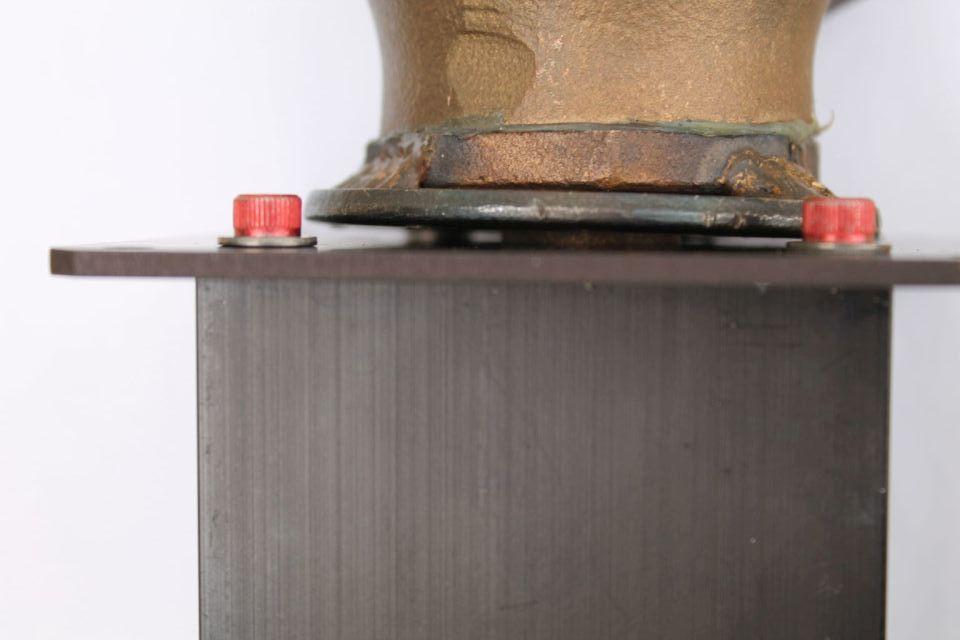
1 DEPAC Dyno Systems 404 Red Bud Trail, Sparta, TN (859) ADL-Lite Dyno Valve Control Kit for Stuska Globe Valve. Includes: Control Panel, Worm-Drive 12V Motor, Tach converter module, and hardware. Important: Your dyno should to be set-up and running with stability under hand control, the ADL-Lite cannot magically correct for an improper installation. Jump to Page 5 and 7 and review proper application guidelines to review.. This system attaches to your existing Stuska flow control globe valve (1.25" or 1"). If you have an existing dyno and have been successful running by hand the Auto ADL-Lite will provide a significant improvement. It is not a speed control but a stabilizing Load Control. ADL-Lite will automatically load the engine as you pickup the throttle, until a stable Engine speed is reached. You can not set a speed but you set a trial Load and then see where the engine wants to run. Then you can change the engine speed by turning the LOAD Knob and then keep the Load knob as set. Now as you smoothly pull back the throttle to an idle It will automatically unload the engine. Now if you pick the throttle up smoothly again the engine should again stop at the RPM previously set. Torque sweeps are easy to make, UP and DWN, and anyone can now run the dyno, if everything is set right.. Note: All dyno controls will become unstable at speeds where engine has a steep torque rise when coming on the cam. You can sweep through this range, but not hold steady. This is a dyno limitation and is most stable from Torque peak on up. Installation: This is a kit where you need to wire your 12 Volt battery and the worm drive motor with #12, or larger, wire. You will need to patch the tach input signal to the divider module to sense the engine s rotation. You will also need to fabricate a secure bracket so that the worm drive can turn your Stuska gate valve. We provide all the parts and fixtures and a coupling that will attach to the rising valve stem. The connection Must be stiff so there is No Twist between motor drive and valve as the valve is opened and closed. Make sure the packing is adjusted just enough for no water leaks, but still easy to turn.. You should move the valve close to the brake for better control response by shortening the water lines--. You need to have the water supply as close as practical to minimize water flow inertia. Keep the total length of the lines (water supply to dyno) as short as possible The Tach module is programmed for the Pulses/Rev of your tach generator so that the signal output is One pulse/rev indicated by a green LED indicator on the Tach Module.. When the engine is running these LEDs should be ON continuously. The ADL-Lite requires a reliable sensing of engine rotation. The system provides a switched output that closes whenever the UP or DOWN rocker switch is pushed. Use this to interface to your data collection system. 1
2 ADL- Lite Dyno Control Operation: Turn the E-Stop knob (to pop-up) to ON. The valve motor will quickly open some and then turn to close. It is seeking where the valve stops turning as it closes and then the Green light turns ON. The system now knows where the valve is closed. The trigger LED indicates when the optical sensor sees the moving edge of a retroreflective patch or pulse from the tach converter module. The trigger LED will fash under 950 RPM and be on steady when the engine is running at higher RPM. The Power On Green LED indicates other diagnostic functions. It will blink off when the motor moves to close the valve and come back ON for normal operation. The Valve will close whenever the engine RPM is less than 950 RPM. At any time the engine is running you can Command the Valve to seek its closed position by turning the Load Knob momentarily to Zero and note the Green LED turn off. The Valve can be turned manually with the Load knob, but only when the engine is stopped, by turning the RATE Knob to Zero and then Pushing either the UP or DWN sweep switch. Use this mode to test the valve for proper operation. The unit can actuate a remote 12V Emergency Stop Relay to enable or disable the engine ignition and fuel system. You can use common automotive 12V relay(s). The system provides an isolated switch output to be used by a data collection system. Anytime the UP or DWN sweep switch is pushed this output will drop from open circuit to less than 5 ohms, for low power signal switching only. When the engine is loaded (part or full) you can adjust the engine RPM by simply turning the LOAD knob. The RATE Knob sets the Rate-of-Change of the LOAD auto-sweep when the UP or DWN switch is pushed and held. The Load Sweep Rate scale is linear from 0 to 10. For steady state (static) tests, turn the RATE knob to zero (for No Sweep). If using the Test Output Switch when you push either UP or DWN switch you will command your data system to record. Make sure that the Globe valve packing is not too tight, preventing the motor from turning the valve and/or seeking the closed position. Make sure there is no binding when the worm drive tries to turn the valve. Use the Manual valve function to exercise the motor valve and sense possible binding. The Special coupling will work with the rising stem valve to full opening. Flats provided for 1/2" wrench. There are natural delays in Loading & Un-loading because of water flow and the time needed to move the valve. Pick up the throttle smoothly to prevent overrevving. Also pull back the throttle smoothly to let the Dyno water drain and prevent the engine from having an excessive load at idle (too much water in the brake). If the Tach signal is lost, while the engine is under load, the valve will move to close. Always use a Rev-Limiter on any engine dyno. The Valve will close when there is no tach signal (lost) or the engine speed is less than 950 RPM. Turning the Load Knob to zero will also command the valve to close. 2
3 DEPAC Dyno Systems 100 Memorial Dr. Nicholasville, KY (859) DC Battery power: Use #12 wire to your 12V Battery. Run #10 or larger for longer than usual cable runs. Best performance comes having 12 to 14+Volts to drive the motor valve. A weak battery voltage will cause the valve to run slower at reduced control performance. You can run as high as 16Volts for better response. A power supply will not work unless it is huge and capable of supply 15 amps peak. That is best done with a fresh good dyno battery. 3
4 DEPAC Dyno Systems 100 Memorial Dr. Nicholasville, KY (859) DEPAC ADL-Lite Dyno Control Kit contents: ADL-Lite operator control panel with Worm Drive motor for 12 to 16VDC Adapter Coupler to connect worm drive to Stuska Style Globe valve (or similar Multi-Turn valve) and Hardware to fabricate the stiff Motor to Stuska Globe valve mount needed as shown.. A tach signal converter module set to divide tach signal to output One pulse per Rev. You need to tap into the existing magnetic tach signal lines (Red is Signal, Black is Ground). If don't have a tach generator you can use the optional Retro-Reflect ROS Optical sensor direst to the ADL-Lite Wire Nuts, 15 Amp ATO fuses, nuts and bolts and all parts to make the mount.. A Base plate to mount valve using a special fixture to center the valve on the drive so you can drill and tap three holes into the standard Stuska Valve mount ring. Stuska holes are not centered. We provide a special cable that allows you to remotely mount a switch to run the control, either Sweep UP (unload) or Sweep Down (Load more). ADL-Lite has outputs to drive a 12V relay for emergency Stop Fuel/Ignition and has an isolated switched output to be used to control a data system. Closed when Up or Down is commanded. Complete Parts Kit shown for Stuska Globe valve (or equivalent 3 to 4 turn valve).. 4
5 General Dyno Set Up considerations. Expect trial and error adjustments You should avoid long water lines from the dyno to the water supply (no matter where the pump is located. The resulting inertia will cause a sluggish response to Load changes. Avoid solid lines and excessive use of 90 deg elbows but rather use rubber hose with smooth bends. If you have a total length of lines more than 30' you may want to place an accumulator near the dyno control valve (inertia reducer). 1.5" for the double Stuska and 1.25" for the single.. You must have enough water flow handle your engine power. Generally you need about 10 GPM per 100 BHP. The pump pressure depends on the size of the valve controlling the inlet water flow. Twice the power requires twice the flow to keep temperature in range. The MOST Important adjustment on your Stuska Brake is a properly sized outlet flow restrictor(s). It is sized so that the internal water temperature never exceeds 125 DegF (50C). On a Dual rotor Stuska it is very important to make sure that each half has the same water flow, so they share the Load evenly. Use a matched set of outlet orifices and change for big changes in engine power.. Note if your monitoring the dyno outlet temperature it will be 10 to 15 degrees cooler than the peak temperature inside the dyno. The outlet water lines need to be just long enough and straight down to flow into a catch tank. Never try to use these lines to pump water to another tank. Use a sump pump in the catch tank or a gravity drain.. You should have the inlet water as cool as practical, which means you also use less water. Avoid pumping hot outlet water back into your supply tank, unless you have a means to cool this water. The pump pressure depends on the engine power and the need to keep the dyno water less than 125 DegF at any time. THE ADL-Lite requires that the valve be opened more than one turn and less than 3 turns at full load. If less than 1 turn then you have too much pump pressure. If more than 3 turns then you have too low pump pressure. Make big changes in pressure. Half water pressure only drops the flow to about 70%. Doubling the pump pressure only increases the flow by about 40%.through the same valve opening. A variable speed 3-phase pump is ideal. The pump power depends on you largest motor. A 10 HP pump can handle up to 1800 BHP. If your existing dyno has lines running to the control panel, to your hand valve, you should move the valve to the top of the dyno (to easier to split the water) so as to shorten the water lines and inertia. You need to provide a good 12V (or more) Dyno battery and #12 cables or #10 if long lines... 5
6 DEPAC Dyno Systems 100 Memorial Dr. Nicholasville, KY (859) Application of the Standard Tach Input divider module: If your dyno has a magnetic Tach sensor you can use the module that accepts this Tach signal and outputs One pulse per Revolution for the ADL-Lite controller. You must tap into the existing Tach signal cable. The Red wire is the hot signal input and Black is the ground side.. This module can be set to convert 2 to 255 pulses with A and B switches. Set in Hex code 3B to skip 59 Tach pulses and pass the 60th pulse to the ADL-Lite Controller. For a Stuska with 50 Pulses per revolution set the AB switch to 31 Hex to skip 49 pulses. Application of the Optional Optical Tach pickup. We supply an Optional retro-reflective optical detector to sense each turn of the dyno. Also you can also use a sensor that can provide a clean voltage pulse (0 to +V) indicating every turn of the dyno. These can be light beam breaker or active magnetic sensors providing a (0-5V) pulse output. The pulse width needs to be more than 1 millisecond and more than +1.5 Volts. A 25 foot long wire cable is provided with a phone connector to interface with a sensor. White = +5V Power, Black & Shield = Ground, Green = +1.5V Pulse on edge sense. Optionally, use the Tach Pulse IN for 0 to +5V pulses (5 to 95% duty cycle). Applying the ROS optical sensor: The ADL-Lite needs to reliably sense every turn of the engine dyno. The supplied optical reflective sensor sends out a Red collimated light beam and a sensitive detector senses light reflected back from a surface. The ADL-Lite ROS sensor gap can to be between and for ma imum fle ibility. A piece of special retro-reflective tape is provided. The ADL Triggers on the moving transition edge of the reflector tape. The tape can be on the drive coupling or drive shaft, on the flywheel, on the front dampener, or anything large enough to reliably detect each turn of the engine/dyno. Mount the sensor slightly off-angle to avoid any direct reflection from a shinny surface. The ADL-Lite panel has an orange trigger LED indicator. The trigger LED will flash ON only when the sensor sees the moving 'edge' of the retro-reflective patch. You can easily test the sensor while the red beam is on the reflective patch. Just pass you hand to break the beam and then see the trigger LED flash for a moment. The reflective tape/patch is on any engine moving part. The trigger LED should be appear ON continuously when sensing the engine is running (one pulse per Revolution). Make sure the sensor and cable will be protected from damage. Make sure ROS lens and the reflective patch is clean of any dirt. Periodically test for proper sensor operation by breaking the beam, with your hand, while the red beam is shinning on the stationary reflective patch. Turn the engine over by hand to see the Trigger LED flash ON & OFF. Press on the valve adapter provided over the Worm Drive gear and use just one set screw and Locktite adhesive to secure. When mounting the Adapter to the Valve shaft you can use adhesive type Locktite 272 AND you can through drill and drive in a pin to lock in place. Do not use a set screw as these will eventually loosen. 6

 is set to (3B) Hexadecimal for")
7 DEPAC Dyno Systems 100 Memorial Dr. Nicholasville, KY (859) Tach Input options: ROS Optical OR Tach Divider Module For 60 PPR (AB) is set to (3B) Hexadecimal for decimal number 59 For 50 PPR (AB) is set to (31) Hex for decimal 49
 on the PC Board.")
8 DEPAC Corp. 100 Memorial Dr., Nicholasville, KY DEPAC ADL-Lite Added Features: We now supply a Special cable that you can use your own Switch to Command LOAD Sweep UP or DOWN.. This cable plugs into the 10 pin adaptor (2 rows of 5 pins) on the PC Board. 3 wire Ribbon Cable: See Diagram on Next Page Center Wire: The common Ground Red Striped wire: When connected to Ground with a push button Switch = Sweep UP Plain Wire: When connected to Ground with a push button Switch = Sweep DOWN You can use an individual push button for each Command or use a rocker switch just like we have on the ADL-Lite panel.
9 DEPAC Corp. 100 Memorial Dr., Nicholasville, KY
10 Tricks and tips.. The ADL-Lite has a lower RPM limit of 950 RPM, below which the valve will close. This setting works well for typical race engines. But If you are running Stock Gas or diesel engines that run at a lower RPM The Control needs to open the valve sooner (or quicker) on speed and be able to Load more at lower RPMs. This is easy to do by just fooling the ADL-Lite that the engine is running faster than it actually is. If you have a 60 tooth dyno speed tach pickup, you can program the Tach module to 30. Now the lowest RPM that the Control will operate will be cut in half to 475 RPM and be able to supply twice as much water to the brake as needed to Load a lower RPM engine. When using the ROS Optical sensor you just need to apply 2 retro-reflective patches 180 degrees apart on a shaft or flywheel starter gear.. So the Control 'sees' 2 pulses per Rev. You can continue on the approach for even lower speed engines. Conversely if you are testing a very high RPM engine you may need to fool the Control by programming 90 into the Tach module, so the valve opens 60/90 as much. NOTE. The Tach divider module is always programmed (by two HEX switches) to be one less than the desired divide ratio. For 60 PPR you program in 59. This means the divider will skip 59 pulses and allow the 60th pulse through to the Control. You can use the 4 pulses per rev on a crank fire system by setting 03 into the Module. The module can also accept a 'pass through' of a single pulse per rev by using the red slide switch on the module (set to /1 instead of /N). So you can adjust the operating range of the ADL-Lite for a wide range of engines and Dyno testing. Steady State Testing (Hold Speed): The Data Switch output is closed whenever the LOAD Switch is pushed UP or DOWN. If you need to do a steady state pull, without a Load sweep, simple turn the RATE control to STOP. The valve will not move and so pushing the LOAD switch either Up or Down the data command switch will close so your data system will record this steady speed only. If you have an averaging system, like the DEPAC, the longer you hold this switch down the longer the data will be averaged, for a more significant result.. Note that the optically-isolated data out switch is for low power use and is 5 Ohms when closed and is intended for low power logic inputs. Trying to have this switch operate a big load, like a relay, may burn it out.
11 DEPAC Dyno Systems 100 Memorial Dr. Nicholasville KY (859) Considerations on the operation of a Stuska brake dyno: Stuska dual rotor dyno require an Equal split of water flow to each half. If not then the dyno runs erratically. Ensure the water flow is split equal for best results. Dyno dual outlet restrictions Need to be matched, to aid in equal water flow as well. A water brake absorber requires water flow proportional to the power absorbed typically about 10 GPM per 100 BHP, mostly to control the dyno water temperature. Setting up a dyno is mostly trial and error and keeping in mind these goals. Keep the dyno Water less than 125 DegF And have the valve open 1 to 3 turns. For High Torque/BHP Engines. The MOST important factor is to never allow the water inside the dyno to exceed 125 Deg F or 50 Celsius. This is directly controlled by the size of the outlet flow restrictor. A good setup is to have a manually adjustable outlet valve that you make easy adjustments to have enough water flow to keep the dyno temperature to not exceed 125 Deg F. BUT, It is also important to Not flow too much water. The dyno just does not work well when 'flooded' with too much water. SO, Close off the outlet until you have at least 110 DegF water temperature. Dyno works best when the dyno water is between 110 DegF and 125 DegF. Note: If you have a sensor for outlet water temperature it will general show readings 10 to 15 degrees cooler than the higher internal dyno water temp.. Once we have the proper outlet water flow we need then to control the inlet flow. The ADL-Lite system works best when we control the valve between 1 and 3 turns. The best way is to control water pressure, which should be mostly steady from Noload to Full-load. If the valve opens less than one turn, when loading your engine near peak torque/load, we have too much water pressure. Conversely if the valve needs to open more than 3 turns then we need more water pressure. NOTE: The flow through the control valve is related to the square root of the water pressure. To double the flow would require 4 times the water pressure. So to cut the flow in half would need 1/4rth the water pressure. So when making pump pressure changes make them Big changes to see any real effect on valve opening. Low Torque/BHP Engines. In cases where you cannot lower the inlet water pressure, an alternate way, to get more turns on the inlet valve and so better control, is to increase the size of the outlet restrictor, forcing more water through the dyno. Note: The ADL-Lite system is designed to use with multi-turn flow control valves. Forget about trying to use on a ¼ turn ball or butterfly valve. 1
12
13


14 DEPAC Dyno Systems 100 Memorial Dr. Nicholasville KY (859)


15 DEPAC Dyno Systems 100 Memorial Dr. Nicholasville KY (859)

16
DEPAC Dyno Systems 100 Memorial Dr. Nicholasville KY (859)
") DEPAC Dyno Systems 100 Memorial Dr. Nicholasville KY 40356 (859) 885-2646 david@depac.com www.depac.com ADL-Lite Dyno Valve Control Kit for SuperFlow Brakes. Includes: Control Panel, 12V motor Worm-Drive
DEPAC Dyno Systems 100 Memorial Dr. Nicholasville KY 40356 (859) 885-2646 david@depac.com www.depac.com ADL-Lite Dyno Valve Control Kit for SuperFlow Brakes. Includes: Control Panel, 12V motor Worm-Drive
DEPAC Dyno Systems 201 Mill St. Rome NY (315)
") DEPAC Dyno Systems 201 Mill St. Rome NY 13440 (315) 339 1265 dave@depac.com www.depac.com MAIN INTRODUCTION: Dyno Control Innovation Auto-Dynamic Load (ADL) Control System for water brake dynos: The ADL
DEPAC Dyno Systems 201 Mill St. Rome NY 13440 (315) 339 1265 dave@depac.com www.depac.com MAIN INTRODUCTION: Dyno Control Innovation Auto-Dynamic Load (ADL) Control System for water brake dynos: The ADL
Open Center Compact Valve Custom Installation Guide Rev A
 200-0762-01 Open Center Compact Valve Custom Installation Guide 602-0575-01 Rev A 2014-12 Overview This guide provides information for completing a custom AutoSteer valve installation on wheeled farm vehicles
CAUTION: READ INSTRUCTIONS CAREFULLY BEFORE STARTING INSTALLATION
 V-Twin MFG. VT No. 32-9500 V-TECH 1 IGNITION KIT, SINGLE FIRE FITS EV SHOVEL, XL THRU 1997 VT No. 32-9503 V-TECH 1 IGNITION KIT, SINGLE FIRE FITS EV, SHOVEL, XL, WITH COIL AND WIRES This is a custom application
ACCEL Distributor Model #A557
 FORM 1627 REV1 INSTALLATION INSTRUCTIONS ACCEL Distributor Model #A557 CAUTION: CAREFULLY READ INSTRUCTIONS BEFORE PROCEEDING. NOT LEGAL FOR USE OR SALE ON POLLUTION CONTROLLED VECHICLES OVERVIEW ACCEL
Stratomaster Maxi Single
 Stratomaster Maxi Single RV-3 Universal Engine RPM and Rotor RPM display The RV-3 unit is a 3.5 instrument providing a universal rev counter that can be adapted to a variety of roles. Typical uses are
SP4 DOCUMENTATION. 1. SP4 Reference manual SP4 console.
 SP4 DOCUMENTATION 1. SP4 Reference manual.... 1 1.1. SP4 console... 1 1.2 Configuration... 3 1.3 SP4 I/O module.... 6 2. Dynamometer Installation... 7 2.1. Installation parts.... 8 2.2. Connectors and
INSTALLATION & OPERATION MANUAL
 INSTALLATION & OPERATION MANUAL MODEL T575N TEMPERATURE COMPENSATED TOTALIZER/PRINTER DOC#: MN-T575N SPONSLER, INC. Liquid and Gas Flow Measuring Devices and Controls LBS ON OFF TRUCK TOTALIZER MODEL T575N
ESD5500E Series Speed Control Unit
 ESD5500E Series Speed Control Unit 1 SPECIFICATIONS INTRODUCTION PERFORMANCE Isochronous Operation ± 0.25% or better Speed Range / Governor 1-7.5 KHz Continuous Speed Drift with Temperature ±1% Maximum
BSR Magic Box Digital ignition control for 4, 6, or 8 cylinder engines
 BSR BSR Magic Box Digital ignition control for 4, 6, or 8 cylinder engines Features Digital Advance The main feature of the Magic Box is the digital advance that replaces conventional weights and springs.
Mallory HyFire Electronic Ignition Control
 Mallory HyFire Electronic Ignition Control PN 690 Parts Included: 1 - Ignition 1 - Harness, Mag Pickup 1-18" Ground Wire 1-100V/1A Diode 4 - Mounting Screws WARNING: During installation, disconnect the
MSD Zero-Cross Distributor Chevrolet - PN 83971
 MSD Zero-Cross Distributor Chevrolet - PN 83971 Parts Included: 1 Distributor 1 Gasket 1 Hold Down & Hardware 1 Gear Lubricant 2 O-Rings IMPORTANT The Separate Pickup Zero-Cross Distributors use two completely
Stratomaster Smart Single
 Stratomaster Smart Single Universal Engine RPM and Rotor RPM display The unit is a 2.25 instrument providing a universal rev that can be adapted to a variety of roles. Typical uses are engine RPM displays
SE-3SCR-LM MANUAL MOTOR LOAD MANAGER
 3714 Kinnear Place Saskatoon, SK Canada S7P 0A6 Ph: (306) 373-5505 Fx: (306) 374-2245 www.littelfuse.com/relayscontrols SE-3SCR-LM MANUAL MOTOR LOAD MANAGER MARCH 5, 2013 REVISION 4 MOTOR LOAD MANAGER
ESC2301. Universal Electronic Governor Controller Operation Manual
 ESC2301 Universal Electronic Governor Controller Operation Manual *Replaces most Woodward, Barber Colman & Cummins Speed Controls Features Smoke Limit Control, Idle Speed Control, 12V or 24V input Suitable
Asynchronous Restriking CDI 2 channel
 Asynchronous Restriking CDI 2 channel Parts List ARC-2 module Decals Power Cable Fuse Specifications Operating Voltage: 8-20V Operating Current: Max Operating RPM: Ambient Temp range: Ignition inputs:
HGM1780 AUTOMATIC GENERATOR MODULE CONTENT 1. SUMMARY PERFORMANCE AND CHARACTERISTICS SPECIFICATION OPERATION...
 CONTENT 1. SUMMARY...4 2. PERFORMANCE AND CHARACTERISTICS...4 3. SPECIFICATION...5 4. OPERATION...6 4.1. DISPLAY PANEL...6 4.2. LCD ICON INSTRUCTION...7 4.3. DISPLAY INSTRUCTIONS...7 4.4. DISPLAY DESCRIPTION...8
Throttle Cable Pull - Patent Pending By: NetGain Controls, Inc.
 Throttle Cable Pull - Patent Pending By: NetGain Controls, Inc. Powering the future! Installation Guide 2011 All Rights Reserved NetGain Controls, Inc. 1 of 8 Introduction Thank you for purchasing a NetGain
EG3000. Generator Electronic Governor Controller Operation Manual
 EG3000 Generator Electronic Governor Controller Operation Manual Smoke Limit Control, Idle Speed Control, suitable for Builtin, Non-Built-in and PT Pump Type Actuator. SP POWERWORLD LTD Willows, Waterside,
STREET/RACE DISTRIBUTOR
 Installation Instructions for STREET/RACE DISTRIBUTOR CAUTION: READ INSTRUCTIONS CAREFULLY BEFORE STARTING INSTALLATION INTRODUCTION The Crane Cams street/race distributor is a high precision system intended
Tri-Spark Ignition System Installation Triple Cylinder TRI-0001
 Tri-Spark Ignition System Installation Triple Cylinder TRI-0001 There are potentially lethal high voltages produced at the ignition coils and spark plugs, therefore every precaution must be taken to prevent
Module 11: Antilock Brakes Systems
 ÂÂ ABS Brake System Antilock Brake System Operation Principles of ABS Braking ABS Master Cylinder Hydraulic Control Unit Wheel Speed Sensors ABS Electronic Control Unit Terms and Definitions Purposes for
CPi. CoiL PACK IGNiTioN FOR AViATiON. For 4,6 and 8 cylinder 4 stroke applications. Please read the entire manual before beginning installation.
 1 CPi CoiL PACK IGNiTioN FOR AViATiON Coil pack (4 cylinder) Coil pack (6 cylinder) For 4,6 and 8 cylinder 4 stroke applications. Please read the entire manual before beginning installation. Software version
Measurement and Analysis of the Operation of a Single-Phase Induction Motor
 Measurement and Analysis of the Operation of a Single-Phase Induction Motor In class I have shown you the carcass of a four-pole, single phase, ¼ HP motor in varying stages of disassembly. In this lab,
MD10. Engine Controller. Installation and User Manual for the MD10 Engine Controller. Full Version
 MD10 Engine Controller Installation and User Manual for the MD10 Engine Controller. Full Version File: MartinMD10rev1.4.doc May 16, 2002 2 READ MANUAL BEFORE INSTALLING UNIT Receipt of shipment and warranty
ANDERSON GREENWOOD SERIES 500 PILOT OPERATED SAFETY RELIEF VALVES INSTALLATION AND MAINTENANCE INSTRUCTIONS
 Before installation these instructions must be fully read and understood TABLE OF CONTENTS 1. General valve description and start-up... 1 2. Main valve maintenance... 1 3. Pilot maintenance... 5 4. Pilot
INSTALLATION INSTRUCTIONS for HI-4 DUAL FIRE MOTORCYCLE IGNITION. Part Number INTRODUCTION REMOVAL OF POINTS IGNITION TO 1977 MODELS
 INSTALLATION INSTRUCTIONS for HI- DUAL FIRE MOTORCYCLE IGNITION Part Number -00 CAUTION: READ INSTRUCTIONS CAREFULLY BEFORE STARTING INSTALLATION INTRODUCTION The HI- ignition system is intended for use
INSTRUCTIONS. #82028 Diesel Nitrous System. Thank you for choosing ZEX products; we are proud to be your manufacturer of choice.
 1 INSTRUCTIONS #82028 Diesel Nitrous System Thank you for choosing ZEX products; we are proud to be your manufacturer of choice. Why our nitrous system is better: 2 Performance enthusiasts know the potential
Servo and Proportional Valves
 Servo and Proportional Valves Servo and proportional valves are used to precisely control the position or speed of an actuator. The valves are different internally but perform the same function. A servo
Table of Contents General Information Specifications Dimensions Programming Instructions Installation Parts List Input Devices
 b Table of Contents General Information 1 Features...1 Specifications 1 Visi-Tach Model Number Description...2 Dimensions 3 Programming Instructions 4 Programming the VT-3........4 Programming the VT-3U...9
INSTALLATION INSTRUCTIONS for HI-1 and HI-2 MOTORCYCLE IGNITIONS. Part Numbers and INTRODUCTION COIL AND SPARK PLUG CABLE CONSIDERATIONS
 INSTALLATION INSTRUCTIONS for HI- and HI- MOTORCYCLE S Part Numbers 8-000 and 8-000 CAUTION: READ INSTRUCTIONS CAREFULLY BEFORE STARTING INSTALLATION INTRODUCTION Crane HI- and HI- ignition systems are
INSTALLATION MANUAL AP60B INSTALLATION MANUAL
 INSTALLATION MANUAL 2. TOOLS REQUIRED The following is a list of tools required to properly install the cruise control. While this unit may be installed without some of the tools listed, it is recommended
BX88175 Installation Instructions ToadStop II Vacuum Brake System
 BX88175 Installation Instructions ToadStop II Vacuum Brake System Serial No. Customer supplied tools & supplies Utility knife, 12VDC tester, drill & bits: (1/8", 1/4", 5/8 ), ¼ socket drive bit, punch,
HGM1770 Automatic Generator Control Module OPERATING MANUAL Smartgen Electronic
 HGM1770 Automatic Generator Control Module OPERATING MANUAL Smartgen Electronic CONTENT 1. SUMMARY... 4 2. PERFORMANCE AND CHARACTERISTICS... 4 3. SPECIFICATIONS... 5 4. OPERATION... 6 5. PROTECTION...
POLESTAR HS Management System
 POLESTAR HS Management System Installation Instructions This document contains the information needed to install and adjust the POLESTAR HS Engine Management System. It assumes that the system already
Flight Systems. Replacement for KASSEC DESCRIPTION
 DESCRIPTION The is a universal generator controller that will start, stop, and provide engine protection for most generators. Universal replacement for both the 90353 and 90354 KASSEC Compatible with most
EDG5500 Electronic Digital Governor With Quikset Display
 1 INTRODUCTION EDG5500 Electronic Digital Governor With Quikset Display GAC s EDG5500 digital governor is designed to regulate engine speed on diesel and gaseous-fueled engines. The EDG system is a suitable
PERTRONIX DIGITAL HP INSTALLATION INSTRUCTIONS
 PERTRONIX DIGITAL HP INSTALLATION INSTRUCTIONS TABLE OF CONTENTS Specifications... 4 General Information... 5 Coil Compatibility... 6 Mounting the Digital HP... 7 Wiring... 8 User Interface... 12 Programming...
SHORT-STOP. Electronic Motor Brake Type G. Instructions and Setup Manual
 Electronic Motor Brake Type G Instructions and Setup Manual Table of Contents Table of Contents Electronic Motor Brake Type G... 1 1. INTRODUCTION... 2 2. DESCRIPTION AND APPLICATIONS... 2 3. SAFETY NOTES...
INSTALLATION INSTRUCTIONS
 INSTALLATION INSTRUCTIONS REAR DISC CONVERSION KIT A126-2 1988-98 C1500 2WD 10" REAR DRUM Thank you for choosing STAINLESS STEEL BRAKES CORPORATION for your braking needs. Pleases take the time to read
MSD Pro-Billet Distributor Buick 400, 430, PN 8552 Buick Nailhead - PN 8524
 MSD Pro-Billet Distributor Buick 400, 430, 455 - PN 8552 Buick Nailhead - PN 8524 Important: Read these instructions before attempting the installation. Parts Included: 1 - Pro-Billet Distributor 1 - Rotor,
SP5 INSTALLATION AND SETUP MANUAL
 SP5 INSTALLATION AND SETUP MANUAL 1 Installation 1.1 Introduction The SP5 System consists of a Data Acquisition unit (DAQ) with two complete Roller control channels, each Roller Control Channel consists
Sensors W2 and E2 are optional. Installation guide, 'Pickle Fork' Back-and-Forth Model Train Controller
 Installation guide, 'Pickle Fork' Back-and-Forth Model Train Controller Azatrax model PFRR-NTO This controller can automate a single track 'back-and-forth' model train layout -- or, one train can travel
10V. the rack of the oil pump must be on the
 P.E.D 20.. ESG2002 series ELECTRONIC GOVERNOR INSTRUCTION A1000C-W ELECTROMAGNETIC ACTUATOR Before inst al l el ectromag neti c, p lea se inspect that the rack of the oil pump shouldn' t be stuck in any
Table of Contents. Introduction Features of the UEGO UEGO 2000 Components 1. Installation Wideband Oxygen Sensor 2 Driver Box 2 Display Head 4
 Table of Contents Introduction Features of the UEGO 2000 1 UEGO 2000 Components 1 Installation Wideband Oxygen Sensor 2 Driver Box 2 Display Head 4 Display Head Operation Description 5 Display Mode 5 Playback
HGM1780. Automatic Genset Controller USER MANUAL. Smartgen Technology
 HGM1780 Automatic Genset Controller USER MANUAL Smartgen Technology Smartgen Technology Co., Ltd No. 28 Jinsuo Road Zhengzhou Henan Province P. R. China Tel: 0086-371-67988888/67981888 0086-371-67991553/67992951
Points Conversion. Optical Trigger Conversion. Specifications. Applications. Optical Trigger - Installation Kits CRANECAMS.
 Points Conversion Optical Trigger Conversion Easy to install in less than 1 hour! Converts points-type distributor to precision optically triggered system! No maintenance! Drives HI-6, HI-6S and most aftermarket
Troubleshooting Guide
 Troubleshooting Guide P/N 0153180 July 1999 P.O. Box 1160 St. Joseph, MO 64502-1160 1-800-255-0317 Fax: 816-360-9379 www.snorkelusa.com GENERAL INFORMATION This manual contains procedures for locating
Instruction Manual Includes:
 Instruction Manual Includes: Page 1: HydraHorse Installation for Basic 2- Horse System Part I: Tank, pump, and electrical supply Page 6: Page 9: Part II: Page Bowls, Brackets, Pipes and Fittings Installing
Instructions for DH142 Series Decoder Installation DH142, DH142P, DH142PS, DH142AT. DH142 Series 1.5 Amp Digital Command Control Decoder
 Instructions for DH142 Series Decoder Installation DH142, DH142P, DH142PS, DH142AT R 450 Cemetery ST #206 Norcross, GA USA 30071 (770)441-7992 FAX (770)441-0759 Web Site: http://www.digitrax.com Digitrax
MSD Pro-Billet Digital E-Curve Distributor Ford 289/302 PN U.S. Patent
 MSD Pro-Billet Digital E-Curve Distributor Ford 289/302 PN 8503 - U.S. Patent 6820602 Important: Read these Instructions before attempting the installation. Parts Included: 1 - Digital E-Curve Distributor
MC Xpress AB Norra Altervägen ALTERSBRUK Sweden
 Installation manual turbo kit SkiDoo/Lynx ACE 900 1 MC Xpress AB Norra Altervägen 821 945 92 ALTERSBRUK Sweden Tel: +46 911 202005 Fax: +46 911 202008 www.mcx.se Supreme of the extreme! Thank you for choosing
User Manual. 1. Introduction
 User Manual 1. Introduction The Tactile Loop Controller has been designed to provide specific logic outputs from a patented EzyLoop Systems tactile Surface Mounted Switch Pad intended primarily for pedestrian
AS-4000 OPERATING INSTRUCTIONS (PS-5000)
") AS-4000 OPERATING INSTRUCTIONS (PS-5000) BASIC OPERATIONS This unit is a state-of-the-art combination of a vehicle alarm and remote starter system. Start by familiarizing yourself with the alarm functions
AS-4000 OPERATING INSTRUCTIONS (PS-5000) BASIC OPERATIONS This unit is a state-of-the-art combination of a vehicle alarm and remote starter system. Start by familiarizing yourself with the alarm functions
Operation and Installation Manual
 Operation and Installation Manual G-Scale Graphics 4118 Clayton Ct. Fort Collins, CO 80525 970-581-3567 GScaleGraphics@comcast.net www.gscalegraphics.net Revision C: Updated 7/15/2009 Page Overview The
ARC4800L Big Red Compressor System
 350 S. St. Charles St. Jasper, In. 47546 Ph. 812.482.2932 Fax 812.634.6632 on the internet: www.ridetech.com ARC4800L Big Red Compressor System 2 ARC7000 ViAir 400C 150psi compressors 2 F9242 5 gallon
Installation Instructions Diesel Nitrous System (#82028)
") Installation Instructions Diesel Nitrous System (#82028) Thank you for choosing ZEX. If at any time you have questions regarding this or any of our products, please call our Nitrous Help support line at
Installation Instructions Diesel Nitrous System (#82028) Thank you for choosing ZEX. If at any time you have questions regarding this or any of our products, please call our Nitrous Help support line at
Reproduction or other use of this Manual, without the express written consent of Vulcan, is prohibited.
 SERVICE MANUAL ELECTRIC BRAISING PANS (30 & 40 GALLON) VE30 VE40 ML-126849 ML-126850 VE40 SHOWN - NOTICE - This Manual is prepared for the use of trained Vulcan Service Technicians and should not be used
TL4076 Top 5 Tips Get to know your TL4076
 TL4076 Top 5 Tips Get to know your TL4076 Thermal Break with Teflon liner (behind fan) Hot End Assembly Fan Heat Block Extruder with toothed gear(brass) and idler (steel) Filament Guide Tube Nozzle Cable
INSTALLATION GUIDE Table of Contents
 CT-3100 Automatic transmission remote engine starter systems. What s included..2 INSTALLATION GUIDE Table of Contents Door lock toggle mode..... 4 Notice...2 Installation points to remember. 2 Features..2
Part #82064 Add-A-Stage EFI Nitrous System
 1 INSTRUCTIONS Part #82064 Add-A-Stage EFI Nitrous System Thank you for choosing products; we are proud to be your manufacturer of choice. Please read this instruction sheet carefully before beginning
VARNA Products 15 GPM (57 LPM) Prelube Kit for MTU 4000 Series Marine Engines
 Prelube Kit for MTU 4000 Series Marine Engines") VARNA Products 15 GPM (57 LPM) Prelube Kit for MTU 4000 Series Marine Engines Installation and Users Manual For the following Prelube Kits: VARNA Products P/N 6423 Kit for 208 VAC 3 Phase VARNA Products
VARNA Products 15 GPM (57 LPM) Prelube Kit for MTU 4000 Series Marine Engines Installation and Users Manual For the following Prelube Kits: VARNA Products P/N 6423 Kit for 208 VAC 3 Phase VARNA Products
CHAPTER 6 IGNITION SYSTEM
 CHAPTER 6 CHAPTER 6 IGNITION SYSTEM CONTENTS PAGE Faraday s Law 02 The magneto System 04 Dynamo/Alternator System 06 Distributor 08 Electronic System 10 Spark Plugs 12 IGNITION SYSTEM Faraday s Law The
EG1069X. Generator Electronic Governor Controller Operation Manual
 EG1069X Generator Electronic Governor Controller Operation Manual Smoke Limit Controller Compatible with Barber Colman Dyn1-1069X series *Use for reference purpose only and not a genuine Barber Colman
Baby Grands Water Cooling Installation Instructions
 Baby Grands Water Cooling Installation Instructions These instructions are designed to help an average racer install a water cooled engine in their Baby Grand racecar. This assumes that the engine is already
POLARSTART PS-3025 SH Multi-Channel Remote Starter System for AUTOMATIC Transmissions
 POLARSTART PS-3025 SH Multi-Channel Remote Starter System for AUTOMATIC Transmissions USER GUIDE INTRODUCTION...2 BASIC REMOTE OPERATION...2 REMOTE-STARTING YOUR VEHICLE...2 DRIVING OFF...2 IDLE MODE...2
User s Manual. Automatic Switch-Mode Battery Charger
 User s Manual Automatic Switch-Mode Battery Charger IMPORTANT Read, understand, and follow these safety rules and operating instructions before using this battery charger. Only authorized and trained service
Tecomotive - tinycwa User Manual
 Tecomotive - tinycwa User Manual Overview Contents - tinycwa controller - Fuse holder - Fuses (15A/30A) - Connector 8 pin (controller) - Connector 4 pin (water pump) - Connector 2 pin (temperature sensor)
BASIC ELECTRICAL MEASUREMENTS By David Navone
 BASIC ELECTRICAL MEASUREMENTS By David Navone Just about every component designed to operate in an automobile was designed to run on a nominal 12 volts. When this voltage, V, is applied across a resistance,
Solstice Electric Fryers SE Series Service Manual
 Solstice Electric Fryers SE Series Service Manual L22-330 R1 (10/12) Notice In the event of problems or questions about your order, contact the Pitco Frialator factory at (603) 225-6684. In the event of
INSIDE YOUR HOLLEY CARBURETOR FUEL INLET SYSTEM
 INSIDE YOUR HOLLEY CARBURETOR The carburetor is quite simply a fuel metering device that operates under the logical and straightforward laws of physics. It has evolved over the years from a very simple
AgXcel GX5 Install Guide for Integration into Trimble. where precision meets the soil... PO Box 1611 Kearney, NE
 where precision meets the soil... AgXcel GX5 Install Guide for Integration into Trimble PO Box 1611 Kearney, NE 68848 877.218.1981 www.agxcel.com where precision meets the soil... AgXcel Integration into
On all settings above 100 horsepower the following precautions should be observed:
 ELECTRONIC FUEL INJECTED 5.0 COYOTE PLATE SYSTEM INSTALLATION INSTRUCTIONS Congratulations on the purchase of your Nitrous Express Coyote Plate system. Nitrous Express utilizes only the highest quality
Model APS-101N Installation Manual
 Programmable Features Model APS-101N Installation Manual Select By Operating Transmitter Press Lock Button Press Unlock Button Siren Indications 1 Chirp 2 Chirps Factory Default 1) Arming Method Passive
Dealing with customer concerns related to electronic throttle bodies By: Bernie Thompson
 Dealing with customer concerns related to electronic throttle bodies By: Bernie Thompson In order to regulate the power produced from the gasoline internal combustion engine (ICE), a restriction is used
G213V STEP MOTOR DRIVE REV 7: March 25, 2011
 Thank you for purchasing the G213V drive. The G213V is part of Geckodrive s new generation of CPLD-based microstep drives. It has short-circuit protection for the motor outputs, over-voltage and under-voltage
INQUIRY: HYROBOTICS CORP SAM LEE ( ) 5988 MID RIVER MALL DR. ST.CHARLES MO TEL : FAX :
 5988 MID RIVER MALL DR. ST.CHARLES MO TEL : FAX :") INQUIRY: HYROBOTICS CORP SAM LEE ( Email : hanrobotic@msn.com ) 5988 MID RIVER MALL DR. ST.CHARLES MO 63304 TEL : 1-636-578-6059 FAX : 1-866-232-5594 1. Picker Body Installation 1-1. Picker Assembly. (Step
INQUIRY: HYROBOTICS CORP SAM LEE ( Email : hanrobotic@msn.com ) 5988 MID RIVER MALL DR. ST.CHARLES MO 63304 TEL : 1-636-578-6059 FAX : 1-866-232-5594 1. Picker Body Installation 1-1. Picker Assembly. (Step
GTWY515, GTWY516* Fast Idle, Shift Interlock, I/O Ford Transit Introduction
 An ISO 9001:2015 Registered Company GTWY515, GTWY516* Fast Idle, Shift Interlock, I/O 2015-2019 Ford Transit Introduction The Gateway 515 and 516 are wheelchair lift safety interlocks which allows lift
RS-351-EDP. Installation Guide
 RS-351-EDP Keyless Entry & Remote Start Installation Guide June 25, 2013 Temporary cover. Color cover is in a separate file. Table Of Contents Installation Considerations... 3 6 Pin Main Wire Harness...
Vacuum Readings for Tuning and Diagnosis
 Vacuum Readings for Tuning and Diagnosis -Henry P. Olsen Once you learn to properly interpret its readings, a vacuum gauge can be one of the most useful tools in your toolbox. 22 FEATURE Some people consider
Error codes Diagnostic plug Read-out Reset Signal Error codes
 Error codes Diagnostic plug Diagnostic plug: 1 = Datalink LED tester (FEN) 3 = activation error codes (TEN) 4 = positive battery terminal (+B) 5 = ground Read-out -Connect LED tester to positive battery
Oregon Fuel Injection
 2001 2006 Dodge Mercedes - Freightliner Sprinter Diagnostics In order to do proper diagnostics you will need a scan tool and some special tools available from Mopar Special Tools http://mopar.snapon.com.
EG1065X. Compatible with Barber Colman* Dyn1-1065X series * Use for reference purpose only and not a genuine Barber Colman product.
 EG1065X Generator Electronic Governor Controller Operation Manual Compatible with Barber Colman* Dyn1-1065X series * Use for reference purpose only and not a genuine Barber Colman product. Headquarters
USER MANUAL PSR-X-T PROGRAMMABLE CDI IGNITION
 www.zeeltronic.com info@zeeltronic.com updated 26.02.2014 program version: 21.140226 USER MANUAL PSR-X-T PROGRAMMABLE CDI IGNITION Very important! Resistor spark plugs must be used, because they produce
I N S T A L L A T I O N I N S T R U C T I O N S TIMING COMMANDER Interface Gauge Ver 7
 I N S T A L L A T I O N I N S T R U C T I O N S 103033 TIMING COMMANDER Interface Gauge Ver 7 This product is designed to interface with the airtemp (IAT) sensor in your vehicle AND your tuner software
Features IN THIS CHAPTER
 CHAPTER THREE 3Special Features IN THIS CHAPTER Motor Braking Regeneration Solutions Sharing the Power Bus: V Bus+ and V Bus- Current Foldback (I T Limit) Front Panel Test Points Resolver Alignment ➂ Special
Crank Trigger Hardware Installation
 Crank Trigger Hardware Installation Step 1 - Bring the engine up to TDC and remove the crank pulley bolt. Step 2 - Install trigger wheel making sure to line up the keyway. You may need to use the bolt
BigStuff3 - GEN3. 1st Gear Spark Retard with Spark Retard Traction Control System (SR 2 ) Rev
 Rev") BigStuff3 - GEN3 1st Gear Spark Retard with Spark Retard Traction Control System (SR 2 ) 12-09 System Description 1st Gear Spark Retard with Spark Retard Traction Control System (SR 2 ) - SR 2 uses two
BigStuff3 - GEN3 1st Gear Spark Retard with Spark Retard Traction Control System (SR 2 ) 12-09 System Description 1st Gear Spark Retard with Spark Retard Traction Control System (SR 2 ) - SR 2 uses two
Installation Instructions
 Quick-Mount Visual Instructions for Mechanical Installation Quick-Mount Visual Instructions 1. Rotate the damper to its failsafe position. If the shaft rotates counterclockwise, mount the CCW side of the
Installation Instructions
 Quick-Mount Visual Instructions for Quick-Mount Visual Instructions 1. Rotate the damper to its failsafe position. If the shaft rotates counterclockwise, mount the CCW side of the actuator out. If it rotates
Hot Tach Pro Operation Manual. Competition Systems, Inc Vista Terrace Lake Forest, CA (949)
") Hot Tach Pro Operation Manual Competition Systems, Inc. 26806 Vista Terrace Lake Forest, CA 92630 (949) 580-6898 Hot Tach Pro Operation Manual Revsion:4/2000 Hot Tach Pro Operation Manual Revsion:4/2000
Hot Tach Pro Operation Manual Competition Systems, Inc. 26806 Vista Terrace Lake Forest, CA 92630 (949) 580-6898 Hot Tach Pro Operation Manual Revsion:4/2000 Hot Tach Pro Operation Manual Revsion:4/2000
Common rail injection system
 Common rail injection system Pressure limiting valve The pressure limiting valve is located directly on the high-pressure fuel rail. Its function is to limit maximum pressure in the high-pressure fuel
Exercise 1-5. Current Protection Devices EXERCISE OBJECTIVE DISCUSSION OUTLINE DISCUSSION. Circuit breakers
 Exercise 1-5 Current Protection Devices EXERCISE OBJECTIVE Describe and test the operation of circuit breakers, fuses, and overload relays. DISCUSSION OUTLINE The Discussion of this exercise covers the
500 Series Troubleshooting Guide for C520 Alternators
 500 Series Troubleshooting Guide for C520 Alternators Hazard Definitions These terms are used to bring attention to presence of hazards of various risk levels or to important information concerning product
4. Remove (4) 10mm and (1) 7mm bolt that holds fascia at front corners, on each side
 10mm and (1) 7mm bolt that holds fascia at front corners, on each side") 2010 Camaro LS3 1. Disconnect battery ground 2. Remove front wheels 3. Remove (5) push pins and (5) #20 torx screws on inner front wheel well liners and remove liners on each side 4. Remove (4) 10mm and
2010 Camaro LS3 1. Disconnect battery ground 2. Remove front wheels 3. Remove (5) push pins and (5) #20 torx screws on inner front wheel well liners and remove liners on each side 4. Remove (4) 10mm and
M9216 Series Electric Spring Return Actuators
 *34636461G* 34-636-461, Rev. J Installation Instructions M9216 Issue Date October 217 M9216 Series Electric Spring Return Actuators Installation IMPORTANT: The M9216 Series actuator is intended to control
CAUTION: CAREFULLY READ INSTRUCTIONS BEFORE PROCEEDING. NOT LEGAL FOR USE OR SALE ON POLLUTION CONTROLLED VEHICLES.
 Twin Tec Installation Instructions for VRFI D Version Fuel Injection Controller CAUTION: CAREFULLY READ INSTRUCTIONS BEFORE PROCEEDING. T LEGAL FOR USE OR SALE ON POLLUTION CONTROLLED VEHICLES. OVERVIEW
DRV-1. Step Motor Drive. User Manual Mentor Avenue Cincinnati, Ohio Tel (513)
") DRV-1 Step Motor Drive User Manual 1776 Mentor Avenue Cincinnati, Ohio 45212 Tel (513) 318-4600 www.resolutionair.com 2 Contents 1 Introduction... 3 1.1 Overview... 3 1.2 Features... 3 1.3 Block Diagram...
DRV-1 Step Motor Drive User Manual 1776 Mentor Avenue Cincinnati, Ohio 45212 Tel (513) 318-4600 www.resolutionair.com 2 Contents 1 Introduction... 3 1.1 Overview... 3 1.2 Features... 3 1.3 Block Diagram...
MAC FAUCETS FA400 WALL MOUNT FAUCETS
 MAC FAUCETS FA400 WALL MOUNT FAUCETS Installation Procedure: Take a moment to view drawings and read special Installation note on pages 4 and 5 of this manual before proceeding with installation. Connect
EG3002. Electronic Engine Governor Controller User Manual
 EG3002 Electronic Engine Governor Controller User Manual Engine Start Smoke Limiting function & IDLE Speed Setting For External, Built-in, PT-Pump type and hydraulic drive actuators Newly added extreme