WATER-COOLED SELF-CONTAINED UNITS MODEL CVWSEK-300BK/DP WATERSIDE ECONOMIZER FOR CSV300B LEFT-HAND VERTICAL R-410A STYLE B
|
|
|
- Shannon McBride
- 5 years ago
- Views:
Transcription
1 WATER-COOLED SELF-CONTAINED UNITS INSTALLATION, OPERATION, & MAINTENANCE Supersedes: IOM5 (514) Form IOM5 (817) MODEL CVWSEK-300BK/DP WATERSIDE ECONOMIZER FOR CSV300B LEFT-HAND VERTICAL R-410A STYLE B Issue Date: August 10, 2017


2 IMPORTANT! READ BEFORE PROCEEDING! GENERAL SAFETY GUIDLINES This equipment is a relatively complicated apparatus. During installation, operation, maintenance or service, individuals may be exposed to certain components or conditions including, but not limited to: refrigerants, oils, materials under pressure, rotating components, and both high and low voltage. Each of these items has the potential, if misused or handled improperly, to cause bodily injury or death. It is the obligation and responsibilty of operating/service personnel to identify and recognize these inherent hazards, protect themselves, and proceed safely in completing their tasks. Failure to comply with any of these requirements could result in serious damage to the equipment and the property in which it is situated, as well as sever personal injury or death to themselves and people at the site. This document is intended for use by owner-authorized operating/service personnel. It is expected that this individual possesses independent training that will enable them to perform their assigned tasks properly and safely. It is essential that, prior to performing any task on this equipment, this individual shall have read and understood this document and any referenced materials. This individual shall also be familiar with and comply with all applicable governmental standards and regulations pertaining to the task in question. SAFETY SYMBOLS The following symbols are used in this document to alert the reader to areas of potential hazard. DANGER indicates an imminently hazardous situation which, if not avoided, will result in death or serious injury. CAUTION identifies a hazard which could lead to damage to the machine, damage to other equipment and/or environmental pollution. Usually and instruction will be given, together with a brief explanation. WARNING indicates a potentially hazardous situation which, if not avoided, could result in death or serious injury. NOTE is used to highlight additional information which may be helpful to you. 2
3 All wiring must be in accordance with published specifications and must be performed ONLY by qualified service personnel. Johnson Controls will not be responsible for damages/problems resulting from improper connections to the controls or application of improper control signals. Failure to follow this will void the manufacturers warranty and cause serious damage to property or injury to persons. TABLE OF CONTENTS 4 Economizer Coil Installation 6 Economizer Piping & Valve Installation 12 Temperature Control Panel Installation 14.. Unit Schematic Diagram 14 WSE Harness Connections 14.. Sequence of Operation 16 Appendix I: 3 Way Waterside Economizer Diverting Valve Adjustment 20 Appendix II. System 450 control model C450CCN-3C quick set up instruction PRIOR TO INSTALLING OR SERVICING THE UNIT, LOCK ALL ELECTRICAL POWER SUPPLY SWITCHES IN THE OFF POSTION. FAILURE TO DISCONNECT POWER SUPPLY MAY RESULT IN ELECTRICAL SHOCK OR EVEN DEATH. 3
4 ECONOMIZER COIL INSTALLATION 1) Position the drain pan using bent down lip of the drain pan according to illustration. Make sure the drain pan is level, do not force it. Push the drain pan against the unit; the pan assembly is designed to rest on the heads of the corner post screws. Using self-drilling screws, attach drain pan support angles to corner posts. 2) Identify the Left-hand and Right-hand WSE Coil Brackets. The Brackets are designed for easy positioning. Press the Left Bracket against the top of the unit then slide it sideways to left until the bracket flange butts against the inside bend of the left unit corner post. The bottom of the Bracket will be inside the drain pan. Repeat the same for the Right Bracket. Attach the Brackets to the corner posts using self-drilling screws in ALL pre-punched clearance holes. Check distance between coil mounting holes centers prior to lifting the coil into the drain pan. 3) Center the U-shaped Top Filler between the WSE Coil Brackets, then align Top Filler with Unit Top. The longer flange (one with pre-punched holes) must face Unit Top front flange. Using supplied self-drilling screws, attach Top Filler to Unit Top. 4) Carefully lift the WSE coil and place it inside of the drain pan, coil connections facing left side of the unit (see illustration). Push the WSE Coil against the Brackets; align holes on the WSE Coil flange with mating holes on the Brackets. 5) Slide provided bolts through the mounting holes on the Brackets and the WSE Coil flange (Insert bolts, threaded end first, through windows in the Brackets). 6) Tighten the WSE Coil to the unit using provided nuts and lock-washers. 7) Attach unit filter rack to entering air face of waterside economizer coil, using self-drilling screws. Applies ONLY to DELUXE Waterside Economizer Kit 8) After the unit piping has been completed, attach Return Bends Cover and Header Cover using provided selfdrilling screws. Exercise care when working around the sharp metal edges of door panels or flanges. These edges can be sharp, and can cause injury. 4


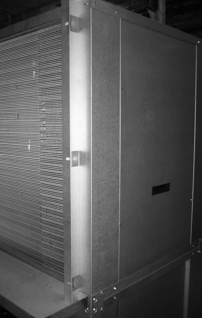
5 DRAIN PAN DRAIN PAN SUPPORT ANGLE LEFT HAND COIL BRACKET RIGHT HAND COIL BRACKET 5
6 BASIC KIT INSTRUCTIONS WATERSIDE ECONOMIZER PIPING AND VALVE INSTALLATION: 1) Refer to the accompanying illustrations for recommended piping and valve mounting layout. The piping layout may be varied from that illustrated, to suit on-site conditions or requirements, provided that the correct water flow arrangement is maintained. The 3-way diverting valve ports are marked A, B, and C. The common port need to be changed from port C to port A if the common port is not A (Please see the appendix I. -3 way waterside economizer diverting valve adjustment).proper orientation of the valve ports is critical for correct operation of the economizer cycle. 2) Wrought copper adapters are provided with the kit to adapt the 3 X 2 NPT valve connections, and the CSV Unit s 2 NPT water inlet connection, to 2-1/8 OD copper tube fittings. The balance of required fittings, and the straight tube lengths, must be field provided (see piping layout illustrations). 3) It is recommended that the connection of the economizer-bypass pipe branch, to the CSV condenser water inlet, be soldered or brazed in place in after being fully threaded into the unit inlet fitting. This will ensure that this joint remains a permanent leak-free connection. (See accompanying photo) 4) The copper adapters for the 3-way valve should be first soldered to the short lengths of tubing connecting them to the adjacent fittings, before being threaded into the valve body. DO NOT install the valve actuator until piping assembly is complete. A lowtemperature solder alloy should be used to prevent annealing or out-of round distortion which can occur with high temperature brazing. Use a good quality pipe sealant on the threaded fittings, and fully tighten the adapters into the brass valve body (Torque should not exceed 75 ft-lb). 5) Assemble the tubing and fittings into the correct arrangement as shown. Tack all tubes in place before soldering to ensure proper fit-up. 6) Pressure test the completed piping assembly with nitrogen. Test pressure should at least equal the working water supply pressure to the unit. Maximum pressure rating for the 3-way diverting valve is 580 psig. 7) Locate the remote electronic temperature sensor (it will be attached to the Temperature Control Panel assembly). The sensor must be securely attached to the surface of the incoming water supply line, upstream of the 3-way valve (use wire ties, tape, or gear clamps). The sensor leads will need to be extended; the two sensor leads must be connected to the terminal strip on the Temperature Control Panel. A wire routing hole is provided in the condenser corner post of the unit (early model units require field punching use a wire protection bushing). 8) Insulate all exposed water piping to prevent sweating; ensure that the water temperature sensor location is well insulated. Insulation should cover horizontal stub-outs on economizer coil; insulation of the vertical coil headers is not required. 9) Install actuator motor to the 3-way diverting valve. Before tightening the self-centering shaft adapter, manually rotate the diverting valve stem to the fully counter-clockwise position. The actuator motor position should be in the fully counter-clockwise position; if not, depress the black de-clutch button and rotate the shaft adapter assembly to the fully CCW position stop. Slide the anti-rotation bracket forward to engage the clip on the connection end of the actuator motor. Do not seat the anti-rotation bracket at the end of the slot; allow sufficient end-play for the motor to float on the valve platform 10) Remove the cover from the actuator, and connect three wire leads to the terminal strip. Lead length must be sufficient to reach the terminal strip of the Temperature Control Panel, which will be installed immediately inside the left hand end panel of the condenser section (behind the water bypass piping / valve assembly). See Panel wiring diagram for proper terminal connections. 6

 ELBOW 2 1/8\" x 2 1/8\" LONG RADIUS (7 PLACES) 7")
7 WATER OUT WATER IN PORT A PORT C PORT B ECONOMIZER IN CONDENSER IN (WATER IN) ECONOMIZER OUT ATTACHED WATER TEMPERATURE SENSOR ELBOW STREET 2 1/8" O.D. x 2 1/8" I.D. TEE 2 1/8" x 2 1/8" x 2 1/8" ROUTE ACTUATOR & SENSOR WIRES TO TEMPERATURE CONTROL PANEL (INSIDE UNIT) ELBOW 2 1/8" x 2 1/8" LONG RADIUS (7 PLACES) 7
8 DELUXE KIT INSTRUCTIONS WATERSIDE ECONOMIZER PIPING AND VALVE INSTALLATION: 1) Refer to the accompanying illustrations for recommended piping and valve mounting layout. The piping layout may be varied from that illustrated, to suit on-site conditions or requirements, provided that the correct water flow arrangement is maintained. The 3-way diverting valve ports are marked A, B, and C. The common port need to be changed from port C to port A if the common port is not A (Please see the appendix I. -3 way waterside economizer diverting valve adjustment). Proper orientation of the valve ports is critical for correct operation of the economizer cycle. 2) All required fittings, and the straight tube lengths, are provided with the kit (see piping assembly A-D illustrations for full instructions). Wrought copper adapters are provided with the kit to adapt the 3 X 2 NPT valve connections, and the CSV Unit s 2 NPT water inlet connection, to 2-1/8 OD copper tube fittings. 3) It is recommended that the connection of the economizer-bypass pipe branch, to the CSV condenser water inlet, be soldered or brazed in place in after being fully threaded into the unit inlet fitting. This will ensure that this joint remains a permanent leak-free connection. (See accompanying photo on page 5) 4) The copper adapters for the 3-way valve should be first soldered to the short lengths of tubing (see piping assembly B ) connecting them to the adjacent fittings, before being threaded into the valve body (Do not install the valve actuator until piping assembly is complete). A low-temperature solder alloy should be used to prevent annealing or out-of round distortion which can occur with high temperature brazing. Use a good quality pipe sealant on the threaded fittings, and fully tighten the adapters into the brass valve body (Torque should not exceed 75 ft-lb). 5) Assemble the tubing and fittings into the correct arrangement as shown. Tack all tubes in place before soldering to ensure proper fit-up. 6) Pressure test the completed piping assembly with nitrogen. Test pressure should at least equal the working water supply pressure to the unit (NOTE: Maximum pressure rating for the 3-way diverting valve is 580 psig). 7) Locate the remote electronic temperature sensor (it will be attached to the Temperature Control Panel assembly). The sensor must be securely attached to the surface of the incoming water supply line, upstream of the 3-way valve (use wire ties, tape, or gear clamps). The two sensor leads must be connected to the terminal strip on the Temperature Control Panel. A wire routing hole is provided in the condenser corner post of the unit (early model units require field punching use a wire protection bushing). 8) Insulate all exposed water piping to prevent sweating; ensure that the water temperature sensor location is well insulated. Insulation should cover horizontal stub-outs on economizer coil; insulation of the vertical coil headers is not required. 9) Install actuator motor to the 3-way diverting valve. Before tightening the self-centering shaft adapter, manually rotate the diverting valve stem to the fully counter-clockwise position. The actuator motor position should be in the fully counter-clockwise position; if not, depress the black de-clutch button and rotate the shaft adapter assembly to the fully CCW position stop. Slide the anti-rotation bracket forward to engage the clip on the connection end of the actuator motor. 10) Remove the cover from the actuator, and connect three wire leads to the terminal strip. Lead length must be sufficient to reach the terminal strip of the Temperature Control Panel, which will be installed immediately inside the left hand end panel of the condenser section (behind the water bypass piping / valve assembly). See Panel wiring diagram for proper terminal connections. 8
9 B A D C Part # Qty Description CLR ELBOW-2 1/8" LG RADIUS 90 DEG CxC CST ELBOW- STREET 2 1/8" 90 DEG CxF CPA-21820M 4 2 1/8" ODS X 2" MPT ADAPTER CPT COPPER TEE 2 1/8" CxCxC RTL-200 3" PLUMBING TUBE - 2" NOM, TYPE L RTL /2" PLUMBING TUBE - 2" NOM, TYPE L RTL /4" PLUMBING TUBE - 2" NOM, TYPE L RTL /8" PLUMBING TUBE - 2" NOM, TYPE L RTL /8" PLUMBING TUBE - 2" NOM, TYPE L RTL /8" PLUMBING TUBE - 2" NOM, TYPE L RTL /4" PLUMBING TUBE - 2" NOM, TYPE L RTL /8" PLUMBING TUBE - 2" NOM, TYPE L RTL /8" PLUMBING TUBE - 2" NOM, TYPE L 9
10 ASSEMBLY A 2 1/8" /2 16 1/8" STRAIGHT PIPE LENGTH USE AS GUIDE ONLY MAINTAIN REFERENCE DIMENSION 13 3/4" STRAIGHT PIPE LENGTH USE AS GUIDE ONLY MAINTAIN REFERENCE DIM. 2 1/8" LONG RADIUS ELBOW, CxC (W02072) 2 1/8" TEE, CxCxC (W040102) ASSEMBLY B 2 1/8" LONG RADIUS STREET ELBOW FTG x C (W02359) BALL VALVE ACTUATOR (M9109) 9 1/8" 9 1/8" 2" NPT 3- WAY BALL VALVE(VG1841FT) 7 3/4" 2 1/8" ODS x 2"MPT ADAPTER (3 PCS.,W01187) 13 5/8" REF. 3" 26 9/16" REF. 2 1/8" LONG RADIUS ELBOW C x C (W02072) 2 PCS. 10
11 ASSEMBLY C 68 3/4" REF. 62 5/8" STRAIGHT PIPE LENGTH USE AS GUIDE ONLY MAINTAIN REFERENCE DIMENSION 2 1/8" LONG RADIUS ELBOW C x C (W02072) 2 PCS. ASSEMBLY D 15 1/4" REF. 9 1/8" STRAIGHT PIPE USE AS GUIDE ONLY 2 1/8" 2 1/8" LONG RADIUS ELBOW C x C (2 PCS., W02072) 11
12 CONTROL PANEL INSTALLATION - WATERSIDE ECONOMIZER Each Waterside Economizer is shipped with a pre-wired Water Temperature Control / Compressor Staging Panel. The panel is complete with a pre-terminated wiring harness, for connection to the economizer plug on the microprocessor control board of the water-cooled unit. Installing Temperature Control Panel 1) The Temperature Control Panel fixture is intended for mounting on the wide condenser clamp rail, supplied with the economizer kit (see photo below). Fasten the panel feet to the rail, using the provided self-drilling screws. 2) Route the pre-terminated 4-wire harness towards the back of the main electrical panel. The harness wiring should be kept away from hot gas piping, and the top of the compressor shell. Pass the wiring into the low voltage section of the main electrical panel, through the thermostat wire entrance hole (see photo below). 3) On the microprocessor, locate the Economizer pin P5 and unplug the two Yellow/Red jumper wires Y1-OUT and ECON and connect these leads to the corresponding colored Yellow/Red harness wires (see table below). On pin P5, connect the G-OUT wire lead to corresponding colored harness wire Gray/Red. Using the provided ¼ tab adapter, create a dual connection on the C-Common tab on the microprocessor board and connect the White harness wire to this dual connection at C. See table below for connecting the harness wires to the corresponding economizer plug connection leads and Common tab on the Microprocessor Board. See wiring schematic for information on pin P5 and C (Common locations). Wire # Single and Dual Compressor Units WSE Control Harness Connection ID Color WSE Temp/Staging Panel Microprocessor Board 1 Yellow/Red TB3-A1 Y1-OUT (P5) 2 Yellow/Red TB3-A2 ECON (P5) 3 Gray/Red TB3-A3 G-OUT (P5) 4 White TB3-A5 C 4) Connect the spade terminals of the other end of the WSE harness to the correspond terminals on TB3 as indicated in the above table. See wiring schematic for more information. 5) Secure the harness to the insulated condenser water piping, or compressor suction piping, in the condensing section of the unit, using wire ties. Ensure that the harness is routed clear of hot surfaces, sharp edges, or screw points. 6) Apply power to the unit, and observe for proper operation of the temperature control, and correct valve actuator rotation (valve position is fully CCW for full mechanical cooling operation, fully CW for economizer mode). 12


13 Temperature Control / Compressor Staging Panel Route Harness Wires over Insulated Suction Piping WSE Control Harness Back of Main Electrical Panel 13
14 WATERSIDE ECONOMIZER HARNESS DUAL COMPRESSOR WIRING SCHEMATIC SEQUENCE OF OPERATION - Single Compressor Models The economizer/unit control package is designed for use with a conventional 24-Volt cooling thermostat. A JOHNSON CONTROL System 450 Control Module C450CCN-3C with remote sensor are used to measure the temperature of the cooling water supplied to the unit. The System 450 Control Module C450CCN-3C will energize/de-energize its relay output stages as dictated by the deviation of the measured water supply temperature to the control set point. The LED in C450CCN-3C indicate their relay status. When water temperatures are suitable for economizing, the control circuit will engage a JOHNSON CONTROLS M9106 actuator motor; driving a 3-way diverting valve. The actuator motor power supply is 24vac, connected to the motor for 2-postion control logic. The control set point for the economizing cycle is user-adjustable. The recommended operating set point is 55 o F. Entering Water Temperatures higher than this value (i.e. 60 o F) will provide only marginal cooling benefit from the economizing coil near continuous operation of the compressor circuits may be required to maintain desired space temperature. Economizer Operation Scenarios Scenario A Entering water temperature is above 55 o F and not adequate for economizer cooling. Scenario B At the factory economizer activation set point of 55 o F or less, the economizer coil will be activated, and compressor operation will be maintained. Total unit capacity is significantly increased, thereby reducing compressor operating time. Water valve will be activated to allow water flow through coil and condensers. 14
15 Scenario C At an entering water temperature of 55 o F or less, and with first and second stage cooling being called by the thermostat (Y1 and Y2), economizer and mechanical cooling will both be active. Scenario D At an entering water temperature of 45 o F or less, and with a call for first stage cooling present from the thermostat (Y1), economizer will be activated and both compressors will be locked-out. Water temperature is deemed to be sufficient to provide sufficient cooling capacity without the need for mechanical cooling. Scenario E At an entering water temperature of 45 o F or less, with unit running in economizer mode and a call for second stage cooling from the thermostat being detected, the unit will turn on compressor 1, until there is no longer a call for second stage cooling. Economizer will run in tandem with compressor 1 in this scenario. Scenario F At an entering water temperature of 45 o F or less, with unit running in economizer mode and a call for second stage cooling from the thermostat being detected, the unit will turn on compressor 1. If there is a continuous call for second stage cooling for more than 20 minutes, compressor 2 will also be activated. Economizer will operate in tandem with compressors 1 and 2 as long a call for second stage cooling is active from the thermostat (Y2). Dual Compressor Unit Sequence of Operation Scenario Y1 Y2 Entering Water Temp COMP 1 COMP 2 Water Flow Economizer A ON OFF Greater Than 55 o F ON OFF Condenser Only OFF B ON OFF 55 o F Or Less ON OFF Cond and Econo Coil ON C ON ON 55 o F Or Less ON ON Cond and Econo Coil ON D ON OFF 45 o F Or Less OFF OFF Cond and Econo Coil ON E ON ON 45 o F Or Less ON OFF Cond and Econo Coil ON F ON ON* 45 o F Or Less ON ON Cond and Econo Coil ON * call for Y2 for 20 minutes or more. Note: If the Economizer Activation Set-point is desired to be higher than 55 o F, the Offset Potentiometer of the C450CCN-3C should be adjusted. If the Offset Potentiometer is not increased, lock-out of the compressor will occur at an EWT higher than that which will allow the economizer coil alone to handle the space cooling load (factory setting: EAS set point minus 10 o F). To adjust Offset value, just go to temperature offset selection screen, press or to select the desired temperature offset value, press to save. The screen example below shown an OFFS value of 3 ( F) for Sensor 1. Please refer to System 450 Control Module C450CCN-3C Quick Setup Instruction for details. The desired switching set-point for the second relay stage is 45 o F. Adjustment of the individual stage differentials is not recommended (excessive valve / compressor cycling may result). FACTORY DEFAULT SETTING 1. SENSOR 2. OUTR 1 3. OUTR 2 Sn-1: F ON 1 :55 ON 2 :45 Sn-2: --- OFF 1 :50 OFF 2 :40 Sn-3: --- ONT 1 :0 ONT 2 :0 OFFS 1 : 0 OFFT 1 :0 OFFT 2 :0 SNF 1 :OFF SNF 2 :OFF SENS 1 :Sn-1 SENS 2 :Sn-1 15
16 Appendix I. 3-Way Waterside Economizer Diverting Valve Adjustment Changing the Common Port from port C to port A The Common Port of valve can be changed from port C to port A if it is necessary. This is accomplished as follows: Remove the handle from the shaft and set it aside. Loosen the wing nut under the mounting plate, which is used to fasten the actuator. Loosen the coupler set screw of the stem. Take out the whole actuator box from the mounting plate and set it aside. Rotate the stem counter-clockwise (CCW) 90º. Assemble the whole actuator box back to the mounting plate. Note: Please notice that the orientation of the tooth on the stem must be matched with the orientation of the tooth on the shaft sleeve of the actuator. Screw the wing nut and the fasten bolt of the stem. Assemble the handle back to the shaft and tighten the screw. Important After changing the valve port, please check and make sure that the port A is the supply return common port. Mounting Plate Adjustment The Actuator Mounting Plate can be rotated (in 90º increments) to a different position for installation in confined spaces. This is accomplished as follows: Remove the handle from the shaft and set it aside. Loosen the wing nut under the mounting plate, which is used to fasten the actuator. Loosen the coupler set screw of the stem. Take out the whole actuator box from the mounting plate and set it aside. Remove the four screws that hold the stem assembly to the mounting plate and set them aside. Remove the stem assembly and mounting plate, rotate the mounting plate around valve top to a desired position. (Mounting plate can only be re-positioned in 90º increments.) Note: Do not rotate the stem solely while remove the stem assembly and mounting plate. Place the stem assembly and mounting plate back to the top of the valve, fasten the four screws to valve body, securing the mounting plate in its new position. Assemble the whole actuator box back to the mounting plate. Important Please make sure that the orientation of the tooth on the stem must be matched with the orientation of the tooth on the shaft sleeve of the actuator. Screw the wing nut and the fasten bolt of the stem. If desired, place the handle back to the shaft, and tighten the screw. 16


17 Actuator box Handle Coupler Set Screw Mounting plate Stem Wing nut Port A Port C The Common Port Valve Body Port B Johnson Control 3-way valve shipped position Remove the handle from the shaft 17


18 Remove the actuator box from the mounting plate Remove the stem assemble and mounting plate Port A Port C The Common Port Port B Mounting plate rotated 180º 18
 90º Port A The Common Port Port C Port B")
19 Port A The Common Port Port C Port B Rotate the stem counter-clockwise (CCW) 90º Port A The Common Port Port C Port B Adjusted Valve 19
20 Appendix II. System 450 Control Model C450CCN-3C Quick Set-Up Instruction Sheet (Refer to System 450 Series Control Models with Relay Outputs Installation Instruction for Full Details) CONTROL FUNCTION & DISPLAY/BUTTONS 1. A System 450 control module has one to three control sensor inputs, and one to ten outputs that provide On/Off control and /or analog control. In this application, we use only one temperature sensor as input (Sn 1), two relay On/Off as outputs (OUTR 1, OUTR 2) 2. Before putting System 450 reset system into operation, make user that sensor 1 jumper is in correct position, which must be positioned across both pins. 3. Startup Screen: When you power a System 450 control model, the LCD displays the control model s current firmware version for approximately five seconds before it displays the Main Screen. 4. Main (Input Status) Screens: During normal operation, the Main Screens automatically scroll through the current status of each input sensor in the control system and display the sensor number, the unit of the measurement, the sensed condition value. The Main Screens are the System 450 default screens. After 2 minutes of inactivity in any screen, the User Interface reverts to the Main Screens. While the Main Screens display, you can pressure repeatedly to scroll through and view the System Status Screens for all inputs and outputs, you can also press and hold and for 5 seconds to access the system s Setup Start Screens and to go to the Sensor Setup Start Screen. 5. System Status Screens: The System Status Screens display current status of all inputs and outputs in the control system. System Status Screens are view-only, selections are not made in Status Screen. Relay output status screens display output number and relay status (On/Off). Pressing repeatedly to scroll and view the System Status Screens for the inputs and outputs in the control system 6. Setup Start Screens: Setup Start Screens are view-only screens, from which you can success the setup screens for the sensors or the displayed output, selections are not made in Setup Start Screens. The Sensor Setup Start Screen is the first screen displayed when you access the setup start screen. From the Sensor Setup Start Screens, press M repeatedly to scroll through the Output Setup Start Screens for all the outputs in the control system. When a Setup Start Screen is displayed, press to go to the setup screens for sensors or the output displayed in the screen, use or to adjust the values when flashing, use to enter the value. In any Setup Start Screens, you can return to the Main Screens by pressing both and simultaneously. Also the UI returns to the Main Screen after 2 minutes of inactivity in any screen. FACTORY DEFAULT SETTING 1. SENSOR 2. OUTR 1 3. OUTR 2 Sn-1: O F ON 1 : 55 ON 2 : 45 Sn-2:--- OFF 1 : 50 OFF 2 : 40 Sn-3:--- ONT 1 : 0 ONT 2 : 0 OFFS 1: 0 OFFT 1 : 0 OFFT 2 : 0 SNF 1 : OFF SNF 2 : OFF SENS 1 : Sn-1 SENS 2 : Sn-1 20
21
22 P.O. Box 1592, York, Pennsylvania USA Subject to change without notice. Printed in USA Copyright by Johnson Controls ALL RIGHTS RESERVED Form IOM5 (817) Issue Date: August 10, 2017 Supersedes: IOM5 (514)
WATER-COOLED SELF-CONTAINED UNITS MODEL CVWSEK-060BK/DP WATERSIDE ECONOMIZER FOR CSV060B LEFT-HAND VERTICAL R-410A STYLE B
 WATER-COOLED SELF-CONTAINED UNITS INSTALLATION, OPERATION, & MAINTENANCE Supersedes: 145.15-IOM1 (514) Form 145.15-IOM1 (817) MODEL CVWSEK-060BK/DP WATERSIDE ECONOMIZER FOR CSV060B LEFT-HAND VERTICAL R-410A
WATER COOLED AIR CONDITIONING UNITS MODEL CVWSEK-060 WATER SIDE ECONOMIZER FOR CSV060B VERTICAL R-410A STYLE B R-410A
 WATER COOLED AIR CONDITIONING UNITS INSTALLATION, OPERATION, & MAINTENANCE SUPERSEDES 145.15-IOM1 (612) Form 145.15-IOM1 (514) MODEL CVWSEK-060 WATER SIDE ECONOMIZER FOR CSV060B VERTICAL R-410A STYLE B
WATER-COOLED SELF-CONTAINED UNITS MODEL CVWSEK-120BKR/DPR WATERSIDE ECONOMIZER FOR CSV096B/120B RIGHT-HAND VERTICAL R-410A STYLE B
 WATER-COOLED SELF-CONTAINED UNITS INSTALLATION, OPERATION, & MAINTENANCE Supersedes: 145.15-IOM2 (514) Form 145.15-IOM2.1 (817) MODEL CVWSEK-120BKR/DPR WATERSIDE ECONOMIZER FOR CSV096B/120B RIGHT-HAND
Model CPV120 Waterside Economizer Kit WATERSIDE ECONOMIZER KIT FOR MODEL CPV 120 WATER-COOLED AIR CONDITIONERS INSTALLATION INSTRUCTIONS
 Model CPV120 Waterside Economizer Kit Supersedes: 145.15-IOM3 (708) Form 145.15-IOM3 (908) WATERSIDE ECONOMIZER KIT FOR MODEL CPV 120 WATER-COOLED AIR CONDITIONERS INSTALLATION INSTRUCTIONS PRIOR TO INSTALLING
MODELS DSH/KSH/DSV/KSV R-410A LOW-AMBIENT KIT
 MODELS DSH/KSH/DSV/KSV R-410A LOW-AMBIENT KIT Supersedes Form145.10-IOM1 (810) Form 145.10-IOM1 (910) LOW-AMBIENT KIT MODELS DSH/KSH/DSV/KSV R-410A AIR CONDITIONING UNITS INSTALLATION INSTRUCTIONS IMPORTANT!
CHILLER MODEL NO. YS SOLID STATE STARTER, MODEL NO. SSS, L B OPTIONAL FACTORY INSTALLED DISCONNECT SWITCH AMPS OR
 WIRING DIAGRAMS CONTRACTOR ORDER NO. JCI CONTRACT NO. JCI ORDER NO. Supersedes: 160.80-PW4 (1099) Form: 160.80-PW4 (215) FIELD CONNECTIONS ROTARY SCREW CHILLER WITH GRAPHIC CONTROL CENTER AND YORK MOD
MODELS SSS 7L-B, 14L-B, 26L-B, 33L-B AND MODELS SSS 7LK-B, 14LK-B, 26LK-B, 33LK-B
 STYLE B LIQUID COOLED SOLID STATE STARTERS REPLACEMENT PARTS Supersedes: 160.00-RP3 (500) Form 160.00-RP3 (614) MODELS SSS 7L-B, 14L-B, 26L-B, 33L-B AND MODELS SSS 7LK-B, 14LK-B, 26LK-B, 33LK-B 00282VIP
FIELD CONNECTIONS FOR YK CHILLER (STYLE G) OPTIVIEW CONTROL CENTER WITH REMOTE MEDIUM VOLTAGE SSS
 OPTIVIEW CONTROL CENTER WITH REMOTE MEDIUM VOLTAGE SSS") Supersedes: 160.75-PW2 (508) Form 160.75-PW2 (311) FIELD CONNECTIONS FOR YK CHILLER (STYLE G) OPTIVIEW CONTROL CENTER WITH REMOTE MEDIUM VOLTAGE SSS WIRING DIAGRAM CONTRACTOR ORDER NO. YORK CONTRACT NO.
Supersedes: 160.75-PW2 (508) Form 160.75-PW2 (311) FIELD CONNECTIONS FOR YK CHILLER (STYLE G) OPTIVIEW CONTROL CENTER WITH REMOTE MEDIUM VOLTAGE SSS WIRING DIAGRAM CONTRACTOR ORDER NO. YORK CONTRACT NO.
RENEWAL PARTS Supersedes: RP4 (1012) Form RP4 (813)
 Form RP4 (813)") VARIABLE SPEED DRIVE RENEWAL PARTS Supersedes: 160.00-RP4 (1012) Form 160.00-RP4 (813) 292 HP 50 HZ, 400VAC (P/N 371-03700-XXX) 351 HP 60 HZ, 460VAC (P/N 371-02767-XXX) 419 HP 50 HZ, 400VAC (P/N 371-03789-XXX)
VARIABLE SPEED DRIVE RENEWAL PARTS Supersedes: 160.00-RP4 (1012) Form 160.00-RP4 (813) 292 HP 50 HZ, 400VAC (P/N 371-03700-XXX) 351 HP 60 HZ, 460VAC (P/N 371-02767-XXX) 419 HP 50 HZ, 400VAC (P/N 371-03789-XXX)
WIRING DIAGRAMS MODEL YK (STYLE G) LIQUID CHILLERS OPTIVIEW CONTROL CENTER WITH SSS, LV VSD W/ MODBUS, & MV VSD
 LIQUID CHILLERS OPTIVIEW CONTROL CENTER WITH SSS, LV VSD W/ MODBUS, & MV VSD") Supersedes 160.75-PW6 (1013) Form 160.75-PW6 (418) WIRING DIAGRAMS MODEL YK (STYLE G) LIQUID CHILLERS OPTIVIEW CONTROL CENTER WITH SSS, LV VSD W/ MODBUS, & MV VSD CONTRACTOR PURCHASER ORDER NO. JOB NAME
Supersedes 160.75-PW6 (1013) Form 160.75-PW6 (418) WIRING DIAGRAMS MODEL YK (STYLE G) LIQUID CHILLERS OPTIVIEW CONTROL CENTER WITH SSS, LV VSD W/ MODBUS, & MV VSD CONTRACTOR PURCHASER ORDER NO. JOB NAME
Installation Instructions
 Outdoor plit Flow Center Kit FCP11BDO (1 pump) FCP21BDO (2 pumps) For plit Geothermal Heat Pump models GZ & H Installation Instructions NOTE: Read the entire instruction manual before starting the installation.
WIRING DIAGRAM MODEL YK (STYLE G) LIQUID CHILLERS OPTIVIEW CONTROL CENTER WITH ELECTRO-MECHANICAL STARTER
 LIQUID CHILLERS OPTIVIEW CONTROL CENTER WITH ELECTRO-MECHANICAL STARTER") PRODUCT DRAWING Supercedes Form 160.75-PW5 (311) Form 160.75-PW5 (1013) WIRING DIAGRAM MODEL YK (STYLE G) LIQUID CHILLERS OPTIVIEW CONTROL CENTER WITH ELECTRO-MECHANICAL STARTER CONTRACTOR PURCHASER ORDER
PRODUCT DRAWING Supercedes Form 160.75-PW5 (311) Form 160.75-PW5 (1013) WIRING DIAGRAM MODEL YK (STYLE G) LIQUID CHILLERS OPTIVIEW CONTROL CENTER WITH ELECTRO-MECHANICAL STARTER CONTRACTOR PURCHASER ORDER
FIELD CONNECTIONS MODEL YK CHILLERS (STYLE F AND G) WITH VARIABLE SPEED DRIVE
 WITH VARIABLE SPEED DRIVE") Supersedes: 160.54-PW6 (513) Form 160.54-PW6 (816) WIRING DIAGRAM CONTRACTOR ORDER NO. YORK CONTRACT NO. YORK ORDER NO. FIELD CONNECTIONS MODEL YK CHILLERS (STYLE F AND G) WITH VARIABLE SPEED DRIVE PURCHASER
Supersedes: 160.54-PW6 (513) Form 160.54-PW6 (816) WIRING DIAGRAM CONTRACTOR ORDER NO. YORK CONTRACT NO. YORK ORDER NO. FIELD CONNECTIONS MODEL YK CHILLERS (STYLE F AND G) WITH VARIABLE SPEED DRIVE PURCHASER
Installation Instructions
 H068A00 H069A00 H070A00 POWER EXHAUST ACCESSORY SINGLE PACKAGE ROOFTOP UNITS 12.5to25TONS Installation Instructions TABLE OF CONTENTS SAFETY CONSIDERATIONS... 1 GENERAL... 1 INSTALLATION... 2 Power Exhaust
Installation Instructions
 Outdoor plit Flow Center Kit FCP11BDO (1 pump) FCP21BDO (2 pumps) For plit Geothermal Heat Pump models GZ & H Installation Instructions NOTE: Read the entire instruction manual before starting the installation.
MANUAL INSTALLATION. Linear Plenum Terminal. LPT Series. v001 Issue Date: 06/06/ Price Industries Limited. All rights reserved.
 MANUA INSTAATION inear Plenum Terminal PT Series v001 Issue Date: 06/06/18 2018 Price Industries imited. All rights reserved. TAB OF CONTNTS General Overview Introduction...1 General Safety Guidelines...1
Installation & Operator s Manual
 Installation & Operator s Manual LS5 Liquid Spray System 2 x 10⁵ Gallon Tanks Installation Instructions 1. Position pump enclosure bracket (#3028485) 4 from rear gusset on driver side of hopper spreader,
CAUTION Danger of sharp metallic edges. Can cause injury. Take care when servicing unit to avoid accidental contact with sharp edges.
 OUTDOOR AIR S Litho U.S.A. 507214-01 2014 12/2014 Supersedes 9/2013 OUTDOOR AIR S INSTALLATION INSTRUCTIONS FOR OUTDOOR AIR S AND OUTDOOR AIR USED WITH 156-300S UNITS Shipping and Packing List Package
FOR OT/HT MODEL CHILLERS STYLE B AND C CONTROL CENTERS , AND
 LOW PRESSURE CUTOUT CONTROL P/N 025-45742-000 INSTALLATION AND MAINTENANCE Supersedes: 160.43-NM4 (1206) Form 160.43-NM4 (1112) 035-21593-000 FOR OT/HT MODEL CHILLERS STYLE B AND C CONTROL CENTERS 366-70488,
ACCESSORY KIT INSTALLATION INSTRUCTIONS
 ACCESSORY KIT INSTALLATION INSTRUCTIONS Low Ambient Accessory For Air Cooled Split-System Air Conditioners YD360/480/600, YJ-30/-40/-50 and J30/40/50 YD Models 642546-UAI-A-080 GENERAL Standard operation
Installation and Commissioning of Auxiliary Power Unit
 Models PC6012 PC6013 PC6014 PC6015 PC6022 PC6023 PC6024 Installation and Commissioning of Auxiliary Power Unit 30-871-21 Rev. E Warning & Cautions Vehicles with longer wheel bases should have the APU mounted
Pathfinder Remote Evaporators
 Installation Manual IM 1203 Pathfinder Remote Evaporators Group: Chillers Part Number: IM1203 Date: September, 2014 For Use With Model AWS-C Air-Cooled Chillers 170 to 550 tons 600 to 1930 kw R-134a 60Hz
FAX
 INSTALLATION INSTRUCTIONS 6090 Air Suspension Kit (pat. pending) 1999-2006 Tahoe, Suburban, Avalanche, Yukon Thank you for purchasing a quality Hellwig Product. PLEASE READ THIS INSTRUCTION SHEET COMPLETELY
M x Series Valve Linkage Kits
 Installation Instructions M9000-51x Issue Date 05/01/02 M9000-51x Series Valve Linkage Kits Installation Parts Included Quantity Description 1* Actuator Mounting Bracket 1* Adjustable Anti-Rotation Slider
Installation Instructions
 CRLOWAMB039A00 CRLOWAMB040A00 CRTRXKIT002A00 ACCESSORY MOTORMASTER I HEAD PRESSURE CONTROL KIT 12.5 TON HEAT PUMP Installation Instructions TABLE OF CONTENTS PACKAGE CONTENTS... 1 PRODUCT USAGE... 2 SAFETY
Rostselmash Torum 740
 Note: Indented items indicate parts included in an assembly listed above Quantity by Model Part Name/Description Part Number 740 Combine Kit Torum 740 4100762 1 Threaded Arm Assembly 2000311-2 1 Header
2-row and All-row systems included.
 Ag Leader Technology Cotton Picker Installation Installation Instructions for John Deere cotton picker models: 2-row and All-row systems included. IMPORTANT: Ensure the model numbers shown above correspond
INSTALLATION INSTRUCTIONS
 INSTALLATION INSTRUCTIONS GMT 560 (4500/5500) CREW CAB (2351A000) Link Mfg. Ltd. 223 15th St. N.E. Sioux Center, IA USA 51250-2120 The CABMATE MODEL 2351A000 fits the 2003 and later GM 4500 / 5500 crew
FAX
 INSTALLATION INSTRUCTIONS 6299 Air Suspension Kit (pat. pending) 2009+ Dodge 1500 Pickup with Rear Coil Springs Thank you for purchasing a quality Hellwig Product. PLEASE READ THIS INSTRUCTION SHEET COMPLETELY
Installation Instructions
 FILCAB Filter Cabinet Sizes 6 --- in., 0 --- in., 4 --- in. For Non---Condensing and Condensing Gas Furnaces and FILCAB Accessory Kits Installation Instructions NOTE: Read the entire instruction manual
COMMERICAL SPLIT SYSTEM KITS AND ACCESSORIES /2012 Supersedes
 COMMERICAL SPLIT SYSTEM KITS AND ACCESSORIES 506950 01 2/2012 Supersedes 506164 01 Litho U.S.A. FLOAT SWITCH KIT INSTALLATION INSTRUCTIONS FOR FLOAT SWITCH KIT (91W69) USED WITH TAA SERIES UNITS RETAIN
M x Series Valve Linkage Kits
 M9000-51x Series Valve Linkage Kits Installation Instructions M9000-51x Part No. 14-1201-13, Rev. G Issued October 16, 2008 Supersedes May 6, 2008 Applications Use the M9000-51x Series Valve Linkage Kits
INSTALL MANUAL. FOR ON LINE ORDERING- E Commerce Visit Our Website
 INSTALL MANUAL FOR ON LINE ORDERING- E Commerce Visit Our Website WWW.PRESSUREGUARD.COM Contact Information Technical Support: Chris@pressureguard.com Sales Support: Sales@pressureguard.com By Phone: 615-227-6024
LOW AMBIENT ACCESSORY INSTALLATION INSTRUCTION
 LOW AMBIENT ACCESSORY INSTALLATION INSTRUCTION MODEL 2LA04704533 FOR 15 THRU 25 TON SINGLE PACKAGE AIR CONDITIONERS GENERAL Table 1: Parts Supplied With Kit The Electronic Low Ambient Controller 2LA04704533
Installation Instructions
 Smart Start Assist Kit For use with Single-Phase Residential Geothermal Heat Pumps 8-733-934-497 Installation Instructions NOTE: Read the entire instruction manual before starting the installation. SAFETY
MODEL ELC-12/40-CVM-D BATTERY CHARGER
 NATIONAL RAILWAY SUPPLY MODEL ELC-12/40-CVM-D BATTERY CHARGER Installing, Operating and Service Instructions for the ELC-12/40-CVM-D Solid State Charger PLEASE SAVE THESE IMPORTANT SAFETY AND OPERATING
Product Instructions. Mixing Station. Features. Specifications. Materials
 Mixing Station The Viega Mixing Station provides supply water temperature modulation when connected to a variety of heat sources such as conventional or condensing boilers, water heaters, or geothermal
CRECOMZR054B00 CRECOMZR055B00. VERTICAL AND HORIZONTAL ECONOMI$ER2 ACCESSORY MEDIUM ROOFTOP UNITS 15 to 27 1/2 TONS WARNING TABLE OF CONTENTS
 CRECOMZR05B00 CRECOMZR055B00 VERTICAL AND HORIZONTAL ECONOMI$ER2 ACCESSORY MEDIUM ROOFTOP UNITS 15 to 27 1/2 TONS TABLE OF CONTENTS PACKAGE USAGE...1 SAFETY CONSIDERATIONS...1 PACKAGE CONTENTS...1 GENERAL...2
Installation Instructions
 Quick-Mount Visual Instructions for Mechanical Installation Quick-Mount Visual Instructions 1. Rotate the damper to its failsafe position. If the shaft rotates counterclockwise, mount the CCW side of the
Reproduction or other use of this Manual, without the express written consent of Vulcan, is prohibited.
 SERVICE MANUAL ELECTRIC BRAISING PANS (30 & 40 GALLON) VE30 VE40 ML-126849 ML-126850 VE40 SHOWN - NOTICE - This Manual is prepared for the use of trained Vulcan Service Technicians and should not be used
SPLIT-SYSTEM AIR-COOLED CONDENSING UNITS DESCRIPTION FEATURES H2CA300, 360, 480 & THRU 50 NOMINAL TONS
 550.13-TG1Y(98) SPLIT-SYSTEM AIR-COOLED CONDENSING UNITS HCA300, 360, 80 & 600 5 THRU 50 NOMINAL TONS HCA80 DESCRIPTION These units are completely assembled, piped and wired at the factory to provide one-piece
SUNLINE 2000 SPLIT-SYSTEM AIR-COOLED CONDENSING UNITS FEATURES DESCRIPTION. H5CE090 & H3CE AND 10 NOMINAL TONS (World 50HZ)
") 550.39-TG1YI (994) SPLIT-SYSTEM AIR-COOLED CONDENSING UNITS H5CE090 & H3CE120 7.5 AND 10 NOMINAL TONS (World 50HZ) HCE090 SUNLINE 2000 DESCRIPTION These Sunline 2000 units are completely assembled, piped
550.39-TG1YI (994) SPLIT-SYSTEM AIR-COOLED CONDENSING UNITS H5CE090 & H3CE120 7.5 AND 10 NOMINAL TONS (World 50HZ) HCE090 SUNLINE 2000 DESCRIPTION These Sunline 2000 units are completely assembled, piped
Induction Power Supplies
 Induction Power Supplies 7.5kW; 135 400kHz 480V version (Integral Heat Station) User s Guide Model 7.5-135/400-3-480 SMD Control Brds Rev. D 5/08 Table of Contents 1. Specifications and features...3 2.
ONBOARD AIR HOOKUP KIT
 ONBOARD AIR HOOKUP KIT PART NO. 20052 (30 amp - 110PSI on, 150PSI off) PART NO. 20053 (30 amp - 85PSI on, 105 PSI off) PART NO. 20055 (30 amp - 90 PSI on, 120 PSI off) IMPORTANT: It is essential that you
MANUAL INSTALLATION. Modular Floor Diffusers. MFD Series. v102 Issue Date: 03/23/ Price Industries Limited. All rights reserved.
 MANUAL INSTALLATION Modular Floor Diffusers MFD Series v102 Issue Date: 03/23/18 2018 Price Industries Limited. All rights reserved. TABLE OF CONTENTS General Overview Introduction...1 General Safety Guidelines...1
Package Unit Modulating Economizer Installation Instructions
 Package Unit Modulating Economizer Installation Instructions Downflow Unit Warning: Recognize this symbol as an indication of Important Safety Information! Read all instructions prior to installation.
ONBOARD AIR SYSTEM FOR ALL VEHICLES APPLICATIONS
 ONBOARD SYSTEM FOR ALL VEHICLES APPLICATIONS Thank you and congratulations on the purchase of a Pacbrake onboard air system. Please read the manual prior to starting to ensure you can complete the installation
MODEL 25-OM-10-C & 25-OA-10-C HYDRAULIC BOOSTER
 SPX Corporation 5885 11th Street Rockford, IL 61109-3699 USA Internet Address: http://www.powerteam.com Tech. Services: (800) 477-8326 Fax: (800) 765-8326 Order Entry: (800) 541-1418 Fax: (800) 288-7031
M Ball Valve Linkage Kit
 M9000-551 Ball Valve Linkage Kit Installation Instructions Part No. 34-636-1816, Rev. B Issued July 6, 2011 Supersedes February 7, 2006 Applications The M9000-551 Ball Valve Linkage Kit (Figure 1) is designed
Installation Instructions
 CRPWREXH068A00 CRPWREXH069A00 CRPWREXH070A00 POWER EXHAUST ACCESSORY SINGLE PACKAGE ROOFTOP UNITS 15 to 25 TONS Installation Instructions TABLE OF CONTENTS SAFETY CONSIDERATIONS... 1 GENERAL... 1 INSTALLATION...
ACCESSORY KIT INSTALLATION INSTRUCTIONS
 ACCESSORY KIT INSTALLATION INSTRUCTIONS Low Ambient Accessory For Air Cooled Split-System Air Conditioners HA300, HB360/480/600, HF-25, HL-30/-40/-50 and J25HA, J30/40/50 HB Models GENERAL These split-system
COMMERICAL SPLIT SYSTEM KITS AND ACCESSORIES /2014 Supersedes 8/2012
 COMMERICAL SPLIT SYSTEM KITS AND ACCESSORIES 506953-01 3/2014 Supersedes 8/2012 Litho U.S.A. MSAV Supply Air Blower VFD Kit INSTALLATION INSTRUCTIONS FOR MSAV (MULTI-STAGE AIR VOLUME) SUPPLY AIR BLOWER
PowerLogic High Density Metering System 4-Meter Enclosure Installation Guide
 PowerLogic High Density Metering System 4-Meter Enclosure Installation Guide 7002-0289-00 Instruction Bulletin HAZARD CATEGORIES AND SPECIAL SYMBOLS Read these instructions carefully and look at the equipment
Package Unit Modulating Economizer Installation Instructions
 Package Unit Modulating Economizer Installation Instructions Downflow Unit Warning: Recognize this symbol as an indication of Important Safety Information! Read all instructions prior to installation.
150 PSI ILLUMINATED DASH PANEL GAUGE KIT
 150 PSI ILLUMINATED DASH PANEL GAUGE KIT PART NO. 10061 (For Use with 20/30 Amp Systems) PART NO. 20062 (For Use with 30/40 Amp Systems) IMPORTANT: It is essential that you and any other operator of this
Installation Instructions Electric Heaters 5 20 kw
 Small Packaged Products 2 to 5 Tons Accessory Electric Heaters Cancels: IIK 564A-24-2 IIK 564A-24- -02 Installation Instructions Electric Heaters 5 20 kw NOTE: Read the entire instruction manual before
A. This Section includes piping and related specialties for general-service compressed-air systems operating at 150 psig or less.
 SECTION 221513 - COMPRESSED-AIR PIPING PART 1 - GENERAL 1.1 SUMMARY A. This Section includes piping and related specialties for general-service compressed-air systems operating at 150 psig or less. 1.2
Installation Instructions
 010A00 011A00 014A00 SMALL ROOFTOP UNITS TWO POSITION OUTDOOR AIR DAMPER 2to15TONS (50/60 Hz) Installation Instructions TABLE OF CONTENTS PACKAGE CONTENTS... 1 PACKAGE USAGE... 1 SAFETY CONSIDERATIONS...
Assembly Instructions
 Assembly Instructions Part Number Description Model Approx. Assembly Time 99994-0903 Windshield Wiper Kit Mule SX 1 Hour WARNING Improper installation of this accessory could result in an accident causing
Instruction Sheet. Subject: Installations Instructions. Air Compressor Kits. Importan
 MULTIPLEX 2100 FUTURE, SELLERSBURG, IN 47172 800-367-4233 WWW.MANITOWOCBEVERAGE.COM/US Instruction Sheet Subject: Installations Instructions Importan Read the following warnings before beginning an installation.
M9206-Bxx-2S Series On/Off Electric Spring Return Actuators
 Installation Instructions M9206-Bxx-2S Issue Date May 14, 2003 M9206-Bxx-2S Series On/Off Electric Spring Return Actuators Installation IMPORTANT: Use this M9206-Bxx-2S Series actuator to control equipment
WARNING IMPORTANT
 75-540.0 5H0847510000 September, 2015 INSTALLATION/SETUP INSTRUCTIONS Electronic Mild Temperature Thermostat gas-fired duct furnace/make-up air units Model Series: D, H, I, & O Application The Electronic
UNIVERSAL PUMP HANGER INSTALLATION INSTRUCTIONS
 UNIVERSAL PUMP HANGER INSTALLATION INSTRUCTIONS WARNING! THESE INSTRUCTIONS MUST BE READ AND FULLY UNDERSTOOD BEFORE BEGINNING INSTALLATION. FAILURE TO FOLLOW THESE INSTRUCTIONS MAY RESULT IN POOR PERFORMANCE,
QTC2015T, 020T, 025T, 030T, 035T, 040T, and 045T
 AIR-COOLED LIQUID CHILLERS HERMETIC SCROLL Renewal Parts New Release Form: QTC-RP (5) QTC05T, 00T, 05T, 030T, 035T, 040T, and 045T STYLE E (60 Hz) 5-46 TON LD8973a Dual Circuit LD897a single circuit r-40a
Installation Instructions Electric Heaters 5 20 kw
 Small Packaged Products to 5 Tons Accessory Electric Heaters Cancels: IIK 564A--1 IIK 564A-- 11-01 Installation Instructions Electric Heaters 5 0 kw NOTE: Read the entire instruction manual before starting
Installation Manual. Mixing Box Control Systems Installation, Operation, and Maintenance Manual. 605 Shiloh Road Plano, Texas
 Installation Manual IOM-MBC-00 08-30-04 Mixing Box Control Systems Installation,, and Maintenance Manual Contents Page Introduction...1 General...1 Safety...1 Inspection...1 Mixing Box Control Systems...2
UNIVERSAL PUMP HANGER INSTALLATION INSTRUCTIONS
 UNIVERSAL PUMP HANGER INSTALLATION INSTRUCTIONS WARNING! THESE INSTRUCTIONS MUST BE READ AND FULLY UNDERSTOOD BEFORE BEGINNING INSTALLATION. FAILURE TO FOLLOW THESE INSTRUCTIONS MAY RESULT IN POOR PERFORMANCE,
Installation Instructions
 NOTE: Read the entire instruction manual before starting the installation. This symbol indicates a change since the last issue. SAFETY CONSIDERATIONS Installing and servicing air conditioning equipment
M9216 Series Electric Spring Return Actuators
 *34636461G* 34-636-461, Rev. J Installation Instructions M9216 Issue Date October 217 M9216 Series Electric Spring Return Actuators Installation IMPORTANT: The M9216 Series actuator is intended to control
ClassicSeries Compressor Installation
 ClassicSeries Compressor Installation Applies to Models: CL21-115 Volts CL22, CL32, CL52-208- 230 Volts Equipment Alert Compressor system must be installed per local plumbing and electrical codes. Note:
START-UP CHECKLIST. Date: Job Name: Customer Name: Address: City: State: Zip: Model Number: Serial Number: Qualified Start-up Technician:
 START-UP INSTRUCTION OPTIMUM 36000 To 72000 BTU S PACKAGE UNITS 3 To 6 Ton START-UP CHECKLIST Date: Job Name: Customer Name: Address: City: State: Zip: Model Number: Serial Number: Qualified Start-up Technician:
Requirements LEO Power Operator Installation Instructions Patents: 5,881,497; 7,316,096; 7,484,333 CAUTION CAUTION WARNING
 CAUTION 80-957-00-00 (08-0) Series 570 Openings 85 to 0 or to 70 Double Lever Arm Application for Frame Reveals (76) to 7 (78mm)* Stop (Push) Side of Installation 5700 LEO Operator Installation Instructions
A419ABG-3C Electronic Temperature Control
 Installation Instructions Issue Date June 16, 2003 A419ABG-3C Electronic Temperature Control Application IMPORTANT: Use this A419ABG-3C Electronic Temperature Control only as an operating control. Where
Eclipse 2000 Service Parts
 This part list contains the service parts for the Eclipse 000 systems. The models that are covered include: CME08 CP08 ERC08 Eclipse 000 Service Parts Table of Contents CME08 Cabinet Page CME08 Interior
START-UP CHECKLIST. Date: Job Name: Customer Name: Address: City: State: Zip: Model Number: Serial Number: Qualified Start-up Technician:
 START-UP INSTRUCTION START-UP CHECKLIST SERIES 5 36000 To 72000 BTU S PACKAGE UNITS 3 To 6 Ton Date: _ Job Name: Customer Name: Address: City: State: Zip: Model Number: Serial Number: Qualified Start-up
Installation Instructions
 Quick-Mount Visual Instructions for Quick-Mount Visual Instructions 1. Rotate the damper to its failsafe position. If the shaft rotates counterclockwise, mount the CCW side of the actuator out. If it rotates
Installation Instructions Studio Makeup Station
 Installation Instructions Studio Makeup Station 30" and 36" Models 5-light 30" Studio Makeup Station 8-light 30" Studio Makeup Station 6-light 36" Studio Makeup Station 9-light 36" Studio Makeup Station
Flow Sensor
 NOTE: Indented items indicate parts included in an assembly listed above Part Name/Description Part Number Quantity Instruction Kit Metalfor 4101091 1 Quick reference sheet 2002831-36 1 Installation instructions
Utility Distribution System
 READ AND SAVE THESE INSTRUCTIONS Utility Distribution System Installation, Operation and Maintenance Manual Warning!! Improper installation, adjustment, alteration, service or maintenance can cause property
MF 9520 / 9540 / 9560, Challenger 540C / 560C
 Ag Leader Combine Installation Note: Indented items indicate parts included in an assembly listed above Part Name/Description Part Number 9520 Quantity by Model 9540 540C Parts Kit 2001312-69 1 1 1 Drill
Installation Instructions
 00A0, 0A0-0A0 080A00 08A00 For Use With Vertical EconoMi$ert IV or EconoMi$ert Only SMALL ROOFTOP UNITS ACCESSORY VERTICAL EXHAUST GAS HEATING/ELECTRIC COOLING, ELECTRIC COOLING, AND HEAT PUMP UNITS TO5TON
ACCESSORY KIT INSTALLATION INSTRUCTIONS
 ACCESSORY KIT INSTALLATION INSTRUCTIONS Low Ambient Accessory For Air Cooled Split-System Air Conditioners HA 300, HB 360 / 480 / 600, HF-25, HL-30 / -40 / -50 Models GENERAL These split-system condensing
INSTALLATION INSTRUCTIONS AND OPERATION MANUAL
 INSTALLATION INSTRUCTIONS AND OPERATION MANUAL UL325-2010 Compliant Commercial and Industrial Door Operator Logic Control Continuous Duty IMPORTANT INSTALLATION INSTRUCTIONS WARNING To reduce the risk
MODEL 8682 SUREFLOW ADAPTIVE OFFSET CONTROLLER
 MODEL 8682 SUREFLOW ADAPTIVE OFFSET CONTROLLER INSTALLATION INSTRUCTIONS WARNING: The Model 8682 Adaptive Offset Controller must be wired to 24 VAC only. Wiring the unit to 110 VAC will cause serious unit
TON KW 60HZ
 AIR-COOLED CONDENSING UNIT HERMETIC SCROLL RENEWAL PARTS New Release Form QCC3-RP (57) MODELS QCC3080C, 085C, 090C, 00C, 0C, 30C, 45C QCC360C STYLES A and B 200-3-60 230-3-60 35-3-60 460-3-60 575-3-60
Temperature Sensor Series
 GENERAL DESCRIPTION The patented* No. 85026-Series Temperature Sensor contains a two-position valve operated by temperature variations around the integral sensing bulb. It is used to vent or block a pneumatic
INSTALLATION INSTRUCTIONS AND OPERATION MANUAL
 INSTALLATION INSTRUCTIONS AND OPERATION MANUAL Commercial and Industrial Fire Door Operator Logic Control Restricted Duty Fire Door Operators IMPORTANT INSTALLATION INSTRUCTIONS WARNING To reduce the risk
ATP-2040 Electric Damper Actuator/Transmitter
 ATP-2040 Electric Damper Actuator/Transmitter Kit Includes 1. Actuator/Transmitter package: factory assembled Actuator (EDA-2040) and Transmitter (DPT-2000). Product Code Number Coupler Size Differential
PRODUCT SAFETY NOTICE
 PRODUCT SAFETY NOTICE Congratulations. This vehicle has been equipped with a Firestone air suspension system. This suspension will enhance the vehicle s handling when loaded, however, the vehicle s performance
GH-BETTIS SERVICE INSTRUCTIONS DISASSEMBLY & REASSEMBLY FOR MODELS HD521-M4, HD721-M4 AND HD731-M4 DOUBLE ACTING SERIES PNEUMATIC ACTUATORS
 GH-BETTIS SERVICE INSTRUCTIONS DISASSEMBLY & REASSEMBLY FOR MODELS HD521-M4, HD721-M4 AND HD731-M4 DOUBLE ACTING SERIES PNEUMATIC ACTUATORS WITH HYDRAULIC CONTROL PACKAGE PART NUMBER: SE-023 REVISION:
INSTALLATION INSTRUCTIONS AND OPERATION MANUAL
 INSTALLATION INSTRUCTIONS AND OPERATION MANUAL NEMA 4X UL325-2010 Compliant Commercial and Industrial Door Operator Logic Control Continuous Duty IMPORTANT INSTALLATION INSTRUCTIONS WARNING To reduce the
ACCESSORY KIT INSTALLATION INSTRUCTIONS
 ACCESSORY KIT INSTALLATION INSTRUCTIONS GENERAL Low Ambient Accessory For Air Cooled Split-System Air Conditioners HA 00, HB 60 / 80 / 600, HF-25, HL-0 / -0 / -50 Models These split-system condensing units
D-70, D-140, D-210, and D-280 Series Electric Non-Spring Return Actuators
 Installation D-70, D-140, D-210, and D-280 Series Electric Non-Spring Return Actuators IMPORTANT: The D- Series actuators are intended to control equipment under normal operating conditions. Where failure
SUNLINE 2000 SPLIT-SYSTEM AIR-COOLED CONDENSING UNITS DESCRIPTION FEATURES H4CE090 & H2CE120 & H1CE /2, 10, & 12-1/2 NOMINAL TONS
 550.23-TG1Y (595) SPLIT-SYSTEM AIR-COOLED CONDENSING UNITS H4CE090 & H2CE120 & H1CE150 7-1/2, 10, & 12-1/2 NOMINAL TONS 8.9-9.5 EER SUNLINE 2000 HCE090 208/230/460 VOLT ONLY 208/230/575 VOLT ONLY DESCRIPTION
John Deere 1420, 1435, 1445 Soft Side
 John Deere 1420, 1435, 1445 Soft Side Parts List & Mounting Instructions Jodale Perry Printed: 2003/07 Standard Parts List Qty Description Photo L&R L&R Rear Cab Brackets Rear Cab Side Panels (Plastic)
Disassembly and Assembly
 K EN R 623 2-00 August 2006 Disassembly and Assembly 2506-15 Industrial Engine M G A (Engine) MGB (Engine) M G D (Engine) Important Safety Information Most accidents that involve product operation, maintenance
ACCESSORY KIT INSTALLATION INSTRUCTIONS
 ACCESSORY KIT INSTALLATION INSTRUCTIONS Low Ambient Accessory For Air Cooled Split-System Air Conditioners HA 00, HB 60 / 80 / 600, HF-25, HL-0 / -0 / -50 Models GENERAL These split-system condensing units
TripTek Tire Car Kit Installation Procedure
 TripTek Tire Car Kit Installation Procedure ANTENNA INSTALLATION 1. Assemble the antenna. Be sure to install the rubber washer and tighten the assembly using a wrench. 2. Magnetically mount the antenna
CAUTION. Even Brakes with a black cable need second vehicle kit Even Brakes with a blue cable need second vehicle kit 98450
 cable not included cable not included Even Brakes with a blue cable need second vehicle kit 98450 Even Brakes with a black cable need second vehicle kit 98400 Check the Even Brake serial number before
Installation Manual. HEPALERT LED LIGHT Kit Installation, Operation, and Maintenance Manual for the TLF Diffuser
 Installation Manual IOM-HEPA-TLF-00 HEPALERT LED LIGHT Kit Installation, Operation, and Maintenance Manual for the TLF Diffuser Contents Page Introduction...1 General...1 Safety...1 Inspection...1 Product