O2/N2O Manifold System Instruction Manual
|
|
|
- Brenda Barrett
- 5 years ago
- Views:
Transcription

1 O2/N2O Manifold System Instruction Manual
2 ! WARNING IMPORTANT: READ MANUAL COMPLETELY BEFORE OPERATING THIS DEVICE This manual contains instructions on periodically required checks to be performed by the user. These checks are necessary to ensure the proper performance of this device and its safety features. RETAIN THIS MANUAL FOR FUTURE REFERENCE CAUTION: Federal law requires this device for use by or on the order of a physician or dentist. CAUTION: Do not attempt to repair or alter this device. Unauthorized repair, alteration or misuse of this device is likely to adversely affect the performance and will void the warranty. CAUTION: Never oil or grease any part of this system. The National Institute for Occupational Safety and Health has issued a warning for dental workers exposed to N2O during administration of N2O/O2 conscious sedation analgesia. NIOSH has recommended that exposures should be minimized. Contact NIOSH to receive NIOSH Publications on Control of Nitrous Oxide in Dental Operatories at Exposure can be minimized by effective controls, including System Maintenance, Ventilation, and Work Practices can effectively reduce N2O concentrations in dental operations. A scavenger system is a significant part of exposure control. Your sedation machine includes a fail-safe and other safety features. It also includes the required and accepted specifications by the ADA Council on dental materials and devices. Which includes; emergency air valve, rebreathing check valve, and resuscitator quick connect. The ADA also requires; the system to be installed by a competent supplier of gases and equipment; the gas storage and delivery system meets the recommendations for the National Fire Protection Association. (See NFPA Code) 2
3 Index Alarm Alarm Installation Diagram Alarm Testing...12 Cylinder Restraint Installation...8 Dealer Instructions...17 Desk Alarm Installation Existing Wall Installation Exposed/Concealed Piping Installation Inspection/Testing...16 Installation Introduction...4 Manifold Manifold Packages...5 Manifold Piping Installation Diagram Operation Purchase Record...22 Rough-In Piping Installation Service Transformer Installation...12 Wall Alarm Installation Warning...2 Warranty...23 Wiring
4 Introduction The Belmed Manifold System conforms with the code requirements specified in NFPA 99-C, Level 3, and include the following code required features: 1. Pressure regulator set at PSI installed on each cylinder 2. Flexible hose of 1000 PSI burst strength 3. Connection between regulator and piping system are approved Diameter Index Safety System (DISS) 4. Check Valve located down stream of each regulator 5. Pressure relief valve for each gas pipeline, set at 75 PSI, located downstream of each check valve 6. Restrainers to adequately secure cylinders from tipping 7. Audible and visual alarm for each gas pipeline, activated by an automatic pressure switch when pipeline pressure is less than 40 PSI or more than 65 PSI. Alarm Panel Desk or Wall Zone Valve Shut Off (Purchase Separately) Manifolds Fig. 1 Regulators and Hoses Triple Outlet Station for O2/N2O/VAC (Purchase Separately) Tank Restraint 4

5 Manifold Packages 2 Oxygen/2 Nitrous Oxide Cylinders with Wall Alarm System Part Number 2022-W Description Includes: Manifold, Alarm, Cables, Regulators, Hoses, Tank Restraints 2 Oxygen/2 Nitrous Oxide Cylinders with Desk Alarm System Part Number 2022-D Description Includes: Manifold, Alarm, Cables, Regulators, Hoses, Tank Restraints 5
6 Installation The Belmed Manifold is designed to be installed with fixed piping exposed or concealed, depending on wall construction. Manifold attaches to wall with three (3) #10 fasteners. Piping Belmed Manifold systems utilize CROSSGUARD SAFETY SYSTEM which is designed to prevent cross-connections between nitrous oxide and oxygen by eliminating common sizes. The Belmed Manifold is supplied with 3/8 O.D. tubing pipeline connector for nitrous oxide and 1/2 O.D. tubing pipeline connector for oxygen. The pipeline connectors attach to the manifold with DISS nuts. THE EMPLOYMENT OF THE DIAMETER INDEXED COPPER TUBING MUST BE INSTALLED THROUGHOUT THE ENTIRE PIPING SYSTEM. Fig. 2! CAUTION THIS DEVICE CONTAINS CROSSGUARD SAFETY SYSTEM Utilizing diameter indexed copper tubing. Reducing pipe sizes or tampering with the CROSSGUARD SAFETY SYSTEM constitutes acceptance of liability by the installer. Refer to instructions. Contact Belmed Inc. with any questions or problems. 6
7 Manifold Manifold cover attaches via tongue and groove arrangement. To attach align cover over gauges and push down to remove cover, place thumbs on the inside of the cover and push outward slightly while lifting. Manifold should be installed so that bottom edge is five (5) feet above floor line. Determine center of wall where manifold is to be attached and measure 67½ (see figure 4)from floor to this point. Secure a #10 fastener at this point and allow head of fastener to protrude ⅜ from wall. Hang manifold onto fastener through keyway mounting hole. Using manifold as a template, level and mark two lower mounting holes. If piping is to be concealed, also mark for two holes on 8⅛ centerline in cutout area of mounting panel. Remove manifold and complete all hole drilling. EXPOSED PIPING INSTALLATION: Secure manifold to wall as described in previous paragraph. Remove dust covers from DISS male outlet connectors and moderately tighten pipeline connectors to manifold. Couple each pipeline connector to fixed piping and silver solder. Refer to figure #3. NOTE: Do not allow dust or other debris to enter manifold block. CONCEALED PIPING INSTALLATION: Drill 2 diameter holes on 8⅛ centerlines at points marked earlier for concealed piping. Cut pipeline connectors 1 above DISS nuts and elbow connectors to suitable lengths of piping and silver solder fittings/ piping. (Refer to figure #3). Allow vertical riser lines to hang loosely for later manifold attachment. Note: Do not allow dust or debris to enter manifold block. 7
8 Manifold (continued) ROUGHED IN PIPING INSTALLATION: If studs are in place but walls not erected, install pipelines as previously described (for either concealed or exposed piping). The bottom edge of DISS nuts on pipeline connectors should be 64½ (see figure 4)above floor line and risers on 8⅛ centerlines for later manifold attachment. Allow vertical risers to hang loosely to provide some play in lines to attach DISS fittings to manifold. PROVIDE INFORMATION FOR DRYWALL INSTALLER WITH HOLE DIMENSIONS. (TWO - 2 DIA. HOLES, 68½ (see figure 4) ABOVE FLOOR, 8½ CENTERS). COMPLETE REST OF PIPELINE INSTALLATION, WHEN COMPLETELY INSTALLED, PERFORM REQUIRED PRESSURE TEST AND CROSS LINE CHECK (see page #2) PURGE PIPELINE SYSTEM WITH INTENDED GAS. CYLINDER RESTRAINT INSTALLATION: Always secure bracket 40 above floor line Dimensions and hole placement shown in figure #3 Use 5/16 (9mm) wall mounting hardware appropriate for wall construction. If concrete, use anchor bolts (at least 2 1/2 long) for concrete and concrete block. Wood screws and flat washers for wood (or appropriate size drywall anchors.) Locate straps and buckles before installation. Use 4 fasteners for cylinder bracket. Fig. 3 CONNECT REGULATORS AND HOSES (see page 18 for regulator adjustment) 8
9 Manifold Installation Concealed Piping 1/2 O.D. Tubing - O2 3/8 O.D. Tubing - N2O Fig. 4 Risers on 8⅛ centerline 2 dia. openings in drywall 67½ 68¼ 64¼ Cut pipeline connectors 2½ above DISS nut and elbow BOTTOM EDGE OF MANIFOLD to be 60 above floor line Floorline 9
10 Manifold Installation Exposed Piping CYLINDER ROOM CONSTRUCTION 1. Separate room or cabinet 2. 1½ hr fire rating 3. Door must lock 4. Room vented, min. 72 sqft 5. Cylinders restrained 6. Do not use room for compressors. Storage of flammable materials or other equipment Risers on 8⅛ centerline NOTE: 24 hr/150 PSI pressure test may be put on manifold. Use supplied relief plugs to close off relief valves during test. REMOVE PLUGS AFTER TEST. Coupling Fig. 5 Keyway mounting hole Outlet connector N2O DISS male Outlet connector O2 DISS male Opening for exposed piping Lower mounting holes Manifold Cover 10
11 Alarm DESK STYLE ALARM INSTALLATION: Route manifold and transformer cables shown on page 14. Route all wires through hole in rear of case. Remove terminal plug from alarm and wire per page 14. Attach upper and lower case with four (4) supplied screws. Special Note: desk alarm may be supplied with plug in type AC adapter instead of remote transformer. To install AC plug in adapter, attach adapter wires to terminals #6 and 7 of alarm and plug into nearest receptacle. Test Alarm. NEW WALL STYLE ALARM INSTALLATION: Attach 3-gang electrical box to studs at a point 5ft above floor line. (studs must be in 16 centers). Gang box has mounting bracket and clamp for easy attachment to studs (nail to wood studs, sheet metal screw to aluminum studs). Gang box must be mounted level and installed in ensure alarm will be flush to finished wall surface. Depth gauge markings are located on side of box for 3/8, 1/2 and 5/8 wall thickness. We recommend gang box be installed slightly below flush to finished wall surface. Route manifold and transformer cables through gang box, remove approximately 6 of cable cover from wiring and strip about 1/2 from each wire end. Clamp cable to gang box with clamp inside box. (Clamp may have to be moved). To attach wires to alarm, remove terminal plug from alarm and attach stripped wire ends to proper terminal (see figure 9). Reconnect plug to alarm, align pins on alarm with holes in gang box and slide alarm into gang box until alarm is flush with wall surface. Test alarm. 11
12 Alarm (continued) EXISTING WALL INSTALLATION: Wall style alarm may be installed in existing walls when walls are hollow and there are drop ceilings or otherwise accessible areas to route cables. Remove mounting bracket from gang box by drilling out rivets with a 1/4 drill bit. Remove clamp. Attach the two metal tabs supplied with gang box to the center top and bottom positions on front of gang box. (Attach tabs so that indentations are inside and facing to rear of gang box). Cut an opening 5¾ W x 3⅞ H in wall at desired alarm site. Attach gang box into opening with switch box supports (Madison Straps) which are installer supplied. Route manifold and transformer cables through gang box, remove approximately 6 of cable cover from wiring and strip about 1/2 from each wire end. Clamp cable to gang box with clamp inside box. (Clamp may have to be moved). To attach wires to alarm, remove terminal plug from alarm and attach stripped wire ends to proper terminal (see figure 6). Reconnect plug to alarm, align pins on alarm with holes in gang box and slide alarm into gang box until alarm is flush with wall surface. Test alarm. TRANSFORMER INSTALLATION: Remote transformer is designed to connect to a 4 x 4 junction box with a 120 volt AC supply. Connect the 120 volt primary side of transformer to 120 Vac supply with wire nuts. Connect the 12 volt AC secondary side of transformer to the 2 conductor wires of alarm cable with wire nuts. Secure cover to junction box. Transformer must be mounted OUTSIDE junction box. Refer to the diagram on page14. (See special note under desk alarm instructions regarding the optional plug in AC adapter type transformer). ALARM TEST: Refer to page 17 of manual for alarm test instructions. Note: if pipeline system and gas tanks are not installed, pressure switch contacts on manifold may be bridged to determine alarm circuit is connected properly. Alarm test procedure described on page 17 must still be performed after the system is completely installed. 12
13 3 Gang Electric box w/ clamps & mounting bracket. Mount to be flush with finished wall. Height is 5ft above floor line. May also be mounted in some existing walls. Alarm Installation Wall Alarm 5 conductor cable route to manifold 2 conductor cable route to transformer ALARM Screw Terminal Plug - Removable from alarm for wiring Wall studs on 16 centers Fig. 6 Wiring Connection to Alarm Removable terminal plug is located on rear of alarm. Pull to right to remove from socket. Attach wires from manifold & transformer to proper screw terminals of plug and reconnect to alarm socket. Terminal NOS.: #1-O2 HI (red) #2-O2 LO (green) #3-COM (black) #4-N2O LO (white) #5-N2O HI (brown) #6 & #7 - transformer wires 13
14 Alarm Installation Desk Alarm 5 conductor cable route to alarm Fig. 7 MANIFOLD 2 conductor cable route to alarm Existing or installed junction box w/ 120V supply 120 VAC Primary wires (black) Wire nuts 12 VAC secondary wires (green) (low voltage) Exposed or concealed electric box (not supplied) TRANSFORMER-Mounted on 4x4 cover plate CONNECT WIRING AS SHOWN AND ATTACH TRANSFORMER TO JUNCTION BOX Cover plate Screw terminal plug - removable from alarm for wiring Transformer Installation NOTE: Desk alarm may also be supplied with optional AC plug-in adapter instead of remote transformer and 2 conductor cable. To install, route adapter wire through opening in case and connect to terminal #6 & #7. Plug adapter into desired 120 volt receptacle. 14
15 Manifold Wiring WHITE - N2O LO COLOR CODED WIRING TERMINAL BLACK COMMON GREEN - O2 LO BROWN - N2O HI RED - O2 HI Fig. 8 NO NC NO NC HI LO BROWN WHITE N2O PRESSURE SWITCH HI LO RED GREEN O2 PRESSURE SWITCH Connect the five conductor wire to the terminal strip in the Manifold. Make sure to connect the proper wire to each terminal using the provided color code system Alarm Wiring Connect the two conductor wire to the plug adapter using terminals 6 & 7. Connect the five conductor wire to the plug adapter using the provided color code system. 2 Conductor to Transformer Fig. 9 5 Conductor to Manifold 15
16 Inspection TESTING: PRESSURE TEST: After installation, each pipeline system must be tested for leakage using dry nitrogen at 150 PSI for 24 hours. Each joint should be checked with soapy water or an approved type leak detector. CROSSLINE TEST: Each gas pipeline MUST be checked to determine that no cross connections have been made. Reduce pipeline pressure to zero and then pressurizing one pipeline to 50 PSI using gas intended for that pipeline. Check each outlet station to determine that gas is being dispensed only from the pipeline being tested. TEST PROCEDURES MUST BE PERFORMED AND ARE VITAL FOR THE SAFE OPERATION OF SYSTEM AS WELL AS YOUR OWN PROTECTION. NOTE: The Belmed Manifold is designed to accept the 24 hr/150 PSI pressure test. Relief valve plugs are supplied with each manifold. Plugs are attached to chain and tag, do not disassemble. To plug relief valves, screw plugs into the ends of both relief valves. DO NOT OVERTIGHTEN, a gentle finger tightening is sufficient to prevent valve seat from lifting during test. REMOVE PLUGS AFTER TEST. 16
17 Dealer Instructions 1. VERIFY THAT SYSTEM HAS BEEN LEAK TESTED, CROSSLINE. 2. INSTALL COVER PLATES ON OUTLET STATIONS 3. INSTALL SECONDARY EQUIPMENT (flowmeters, mounting brackets, etc) 4. TEST FOR CROSSED LINES a. use quick connect without machine attached to bleed system to zero b. connect oxygen and nitrous oxide cylinders to manifold c. chain cylinders to wall d. turn on oxygen ONLY (make sure nitrous oxide pressure is zero) e. insert quick connects into outlet stations f. gas should flow ONLY from oxygen outlets g. turn off oxygen cylinder h. bleed oxygen line pressure to zero i. repeat procedure with nitrous oxide 5. TEST ALARM AND ADJUST REGULATORS a. remove cap nut located on front of regulator b. turn on alarm c. establish 5 liter flow of oxygen on flowmeter d. turn adjustment screw on regulator counter clockwise until line pressure is just below 40 PSI e. oxygen LO indicator light and audio signal should come on, depress reset button to cancel audio signal f. turn adjustment screw clockwise until line pressure is just about 65 PSI g. oxygen HI indicator light and audio signal should come on, depress reset button to cancel audio signal h. adjust oxygen pressure back to 50 PSI i. adjust other oxygen regulator(s) to 50 PSI if required j. replace cap nuts on regulators k. repeat procedure with nitrous oxide 6. PLACE INSTRUCTION MANUAL AND OPERATION INSTRUCTIONS ON WALL NEXT TO MANIFOLD 7. ENSURE WARRANTY CARDS ARE COMPLETED AND RETURNED TO BELMED 8. DEMONSTRATE SYSTEM TO DOCTOR 17
18 Service NOTE: With exception of bulb replacement, all service on manifold system should be performed by a qualified, experienced service person ONLY. REGULATOR ADJUSTMENT Regulator line pressure should be 50 PSI at full cylinder pressure. Regulators should be adjusted with gas flowing. Connect gas machine to gas pipeline and establish a 3 LPM flow. Remove cap nut located on front of regulator. Turn clockwise to increase pressure and counter clockwise to decrease pressure. (see figure 10) PRESSURE SWITCH ADJUSTMENT NOTE: Top view drawing of Pressure Switch on right shows both high (NO) terminal and low (NC) terminal for illustration purposes only. Pressure switches on manifold will have only one terminal, either high (NO) or low (NC). First remove soft rubber cover from center of switch by gently prying off with small flat bladed screwdriver (or similar tool). This will allow access to 7/32 hex socket. Replace cover after adjustment. (see figure 11) HIGH PRESSURE ADJUSTMENT (normally open terminal) Turn Allen wrench RIGHT to INCREASE pressure Turn Allen wrench LEFT to DECREASE pressure. LOW PRESSURE ADJUSTMENT (normally closed terminal) Turn RIGHT to INCREASE setting. Turn LEFT to DECREASE setting NOTE: Right indicates clockwise direction and left counter clockwise. Color coding; RED O2 HI, GREEN O2 LO, BROWN N2O HI, WHITE N2O LO, BLACK COMMON (Figure #) Regulator Adjustment Pressure Switch Adjustment Increase NC C NO Decrease Fig. 10 Fig
19 Service RELIEF VALVE Valve must be reset to 75 PSI relief after servicing IF A PROBLEM EXIST IT IS RECOMMENDED ENTIRE VALVE BE REPLACED (see figure 12) ALARM BULB REPLACEMENT A spare bulb is located within reset button housing disconnect alarm from power source. Gently pull on reset and expose housing. A tweezer type tool or someone with small fingers can remove bulb by gently pulling toward you. Replacement bulb #: 7382 (see figure 13) Fuse Replacement: Fuse is located at right rear of alarm. Replace with 20mm 0.5 amp fuse. Relief Valve Alarm Bulb Replacement Adj. Screw Jam Nut Spring Cup/Seal Body Bulb Lens Fig. 12 Fig
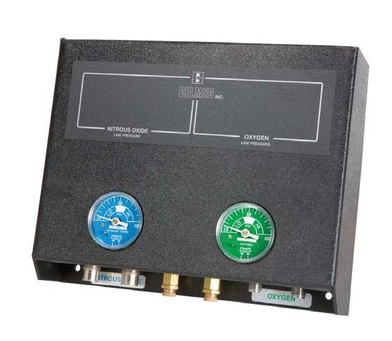
20 Operation NORMAL OPERATION: AT the start of each work day, open all cylinder valves for each gas. CAUTION: OPEN CYLINDER VALVES SLOWLY. If more than one cylinder for a gas, read cylinder pressure on each regulator gauge and close those cylinders with the highest pressure. This will leave only the cylinder with the lowest pressure open and maintaining the fullest cylinders in reserve. Your gas supplier will supply tags to identify the in use and reserve cylinders. After turning on proper cylinders, observe line pressure gauge for each gas on manifold. Gauge indicator should be in the white area of dial between LO and HI (preferable at 50 PSI). After turning on cylinders and verifying correct line pressure, turn on gas supply alarm. Actuate PUSH TO TEST buttons to determine that audio and visual indicators are working normally. If during the work day, any cylinder becomes empty, the gas supply alarm will actuate a LO condition. When this occurs, depress reset button on alarm to cancel audio signal, open the reserve cylinder valve and reorder a replacement cylinder from gas supplier. The alarm will automatically reset when normal pressure is restored. HIGH PRESSURE SIGNAL: Indicates an abnormal pressure condition exists. Turn off system immediately and call a qualified service person. NOTE: TURN OFF ALL CYLINDERS WHEN FACILITY IS UNATTENDED. Oxygen is a rapid accelerator of fire. With cylinder valves turned off, there is less danger in the event of an unrelated fire. This practice also provides for frequent checks on proper manifold operation and pressures. 20
21 Operation (continued) RECORDING CYLINDER REPLACEMENT: OXYGEN: Replace cylinder when gauge on regulator reaches 200 PSI. The gauge will register approximately 2000 PSI when fully charged. Oxygen is in a gaseous phase within the cylinder. As the oxygen is used, the pressure indicated on regulator gauge will fall proportionally to the contents. (i.e.: 1500 PSI - 3/4 full, 1000 PSI - 1/2 full, etc.). Oxygen is generally supplied in H size cylinders and a fully charged cylinder contains 6909 liters of oxygen (244 cu. ft.) NITROUS OXIDE: Replace cylinder when pressure gauge on regulator reaches 500 PSI. The gauge will register approximately 750 PSI when fully charged with LIQUID nitrous oxide. As nitrous oxide is used, the liquid converts to a gaseous phase within the cylinder and the gauge will continue to register 750 PSI until all liquid converts to a gas within the cylinder. After this occurs, the gauge on the regulator will indicate a decrease in pressure as the remaining nitrous oxide is used. Nitrous oxide is generally supplied in G size cylinders and a fully charged cylinder contains approximately 13,800 liters of nitrous oxide (488 cu. ft.) NEVER ATTEMPT TO REPAIR OR MAKE CHANGES TO THE SYSTEM. IF IN DOUBT ABOUT PROPER OPERATION, A REPUTABLE SERVICE PERSON, EXPERIENCED WITH MANIFOLD SYSTEMS SHOULD BE CALLED AT ONCE 21
22 Purchase Record MODEL NO. SERIAL NO. PURCHASE DATE Notes 22
23 Warranty Definition of Warranty Return: A product or part covered by the Belmed, Inc. warranty, that fails while the terms of the warranty are in effect. THIS WARRANTY IS GIVEN IN PLACE OF ALL OTHER WARRANTIES, EXPRESSED OR IMPLIED, OF MERCHANTABILITY, FITNESS FOR A PARTICULAR PURPOSE OR OTHERWISE. No statement or claim about the product by any employee, agent, representative or dealer of Belmed, Inc. shall constitute a warranty by Belmed, Inc. or give rise to any liability or obligation of Belmed, Inc. Subject to the next sentence, Belmed, Inc warrants that each product or part shall be free from defects in workmanship and materials, under normal use and with appropriate maintenance, for one (1) year from the date of delivery to customer. For plastic, rubber and disposable parts or items Belmed, Inc. warrants only that each such part and item shall be free from defects in workmanship and materials at the time of delivery to the customer. Belmed, Inc. s obligation for breach of this warranty, or for negligence or otherwise, shall be strictly and exclusively limited to Belmed Inc. s choice of repair or replacement of the product or part. This warranty shall be void for any product on which the serial number has been altered, defaced or removed. Belmed, Inc. shall not be liable for any damage, injury or loss arising out of the use of the product, whether as a result of a defect in the product or otherwise, if, prior to such damage, injury or loss, the product was (1) damaged, misused, or misapplied; (2) repaired, altered or modified by persons other than Belmed, Inc. (3) not installed in strict compliance with applicable codes and ordinances; or (4) not installed by Belmed, Inc. or an authorized Belmed, Inc. dealer. UNDER NO CIRCUMSTANCES SHALL BELMED, INC. BE LIABLE FOR INCIDENTAL OR CONSEQUENTIAL DAMAGES AS THOSE TERMS ARE DEFINED IN THE UNIFORM COMMERCIAL CODE. Important: Traceability/Warranty Registration Medical device legislation of 1976 mandates traceability of this equipment. Please fill out and return warranty card. 23

24 Order: Fax: Mail To: PO Box 247 Red Lion, PA Ship To: 887 Delta Rd Red Lion, PA Contact Us: Local: Toll Free Tech Support:
VANGUARD A EZ INSTALL OPERATOR S MANUAL
 Parker Hannifin Corporation Porter Instrument Division 245 Township Line Rd. P.O. Box 907 Hatfield, PA 19440-0907 USA (215) 723-4000 / fax (215) 723-5106 VANGUARD A EZ INSTALL OPERATOR S MANUAL FM-1145
MAY Nitrous Oxide/Oxygen Sedation Equipment
 MAY 2018 Nitrous Oxide/Oxygen Sedation Equipment 1 QUAlitY SinCE 1976 FLOWMETER HEAD DIMENSIONS 8.75 H X 3.75 W X 10.25 D PC-7 Flowmeter WEIGHT OF FLOWMETER HEAD 5lbs BAG AND OUTLET DIAMETER 22mm (approx.
Table of Contents Next FLO-SAFE Manifold System Pre-Installation Kit Matrx Toll-Free: Technical Support: Fax: Rev.
 FLO-SAFE Manifold System Pre-Installation Kit Instruction Manual Matrx 145 Mid County Drive Orchard Park, New York 14127 716-662-6650 Toll-Free: 800-847-1000 Technical Support: 888-279-1260 Fax: 716-662-8440
Lifeline Medical Systems
 Installation, Operation and Service Manual Lifeline Medical Systems Fully-Automatic Manifold For Use With Liquid Cylinders LQ x HP Liquid x High-Pressure Models Part No. 6-847703-00 Rev. C00 Pg. 1 Introduction
Model AS-FM64 Wall Mount. Full Motion Television Wall Mount
 Model AS-FM64 Wall Mount Full Motion Television Wall Mount Getting Started Introduction Congratulations on the purchase of your new Audio Solutions AS-FM64 Television Wall Mount. For maximum benefit, please
CRD610 Automatic Fitting Inserter
 CRD610 Automatic Fitting Inserter OPERATIONS MANUAL VERSION 1.2 LAST EDITED 12.12.2018 cleanroomdevices.com 1 Table of Contents Title Page. 1 Table of Contents...2 1.0 General Product & Safety Information....3
Model FM2642 Wall Mount. Full Motion Television Wall Mount
 Model FM2642 Wall Mount Full Motion Television Wall Mount Getting Started Introduction Congratulations on the purchase of your new Audio Solutions FM2642 Television Wall Mount. For maximum benefit, please
Nitrous Oxide/Oxygen Sedation Equipment
 Nitrous Oxide/ Sedation Equipment 2017 Price List www.belmedinc.com 888-723-5893 Mail to: PO Box 247 Red Lion, PA 17356-0247 Ship to: 887 Delta Rd. Red Lion, PA 17356-0247 Contact Us: 717-246-5500 Fax:
CRD600 Automatic Fitting Inserter
 CRD600 Automatic Fitting Inserter OPERATIONS MANUAL VERSION 2.3 LAST EDITED 12.07.2018 cleanroomdevices.com 1 Table of Contents Title Page.. 1 Table of Contents. 2 1.0 General Product & Safety Information...3
Veterinary Scavenger Interface
 Veterinary Scavenger Interface Installation and Operation Manual MX101300i 1-800-Midmark www.midmark.com Part No. 10553300 Rev.G (9/23/13) Table of Contents Section 1 UNPACKING...2 1.1 Examining Packaged
Anthro Mobile Device Charging Carts and Cabinets Owners Manual
 Anthro Mobile Device Charging Carts and Cabinets Owners Manual TECHNOLOGY FURNITURE Hello! Thank you for choosing Anthro. Anthro's Tablet Charging Carts and Cabinets are designed to automatically charge
Colt Series C400, C500
 Colt Series C400, C500 RP/IS-A-C400/C500 C400 OSY Reduced Pressure Zone Assemblies Reduced Pressure Detector Assemblies Sizes: 2 1 2" 10" (65 250mm) Installation Service Repair Kits Maintenance For other
Series 957, 957N, 957Z, 957RPDA, 957NRPDA, 957ZRPDA
 Series 957, 957N, 957Z, 957RPDA, 957NRPDA, 957ZRPDA Reduced Pressure Zone Assemblies Reduced Pressure Detector Assemblies Sizes: 2 1 2" 10" (65 250mm) Installation Service Repair Kits Maintenance RP/IS-957/957RPDA
CLEAN ROOM DEVICES, LLC "WHERE TUBING AND FITTINGS COME TOGETHER"
 CLEAN ROOM DEVICES, LLC "WHERE TUBING AND FITTINGS COME TOGETHER" CRD600AF Automatic Fitting Inserter With Auto Feed OPERATIONS MANUAL (Shown with optional alcohol dispenser) 1 VERSION 1.1 LAST EDITED
Dual/Triple Manifold Water Filtration Systems Instruction Manual
 3M TM Water Filtration Products Dual/Triple Manifold Water Filtration Systems Instruction Manual High Flow Series Water Filtration Systems Installer: Please leave this manual with owner/operator. 3M Water
Read this entire manual before operation begins.
 Read this entire manual before operation begins. Record below the following information which is located on the serial number data plate. Serial No. Model No. Date of Installation Contents Specifications.............
Model T2642 Wall Mount. Television Wall Mount with Tilt Option
 Model T2642 Wall Mount Television Wall Mount with Tilt Option Getting Started Introduction Congratulations on the purchase of your new Audio Solutions T2642 Television Wall Mount. For maximum benefit,
4000SS. For other repair kits and service parts, send for Ames Repair Parts Price List, PL-A-RP-BPD.
 Series 4000SS RP/IS-A-4000SS 4000SS Reduced Pressure Zone Assemblies Sizes: 8" 10" (200 250mm) Installation Service Repair Kits Maintenance For other repair kits and service parts, send for Ames Repair
Scale Feeder Manifold Water Filtration System Instruction Manual
 3M TM Water Filtration Products Scale Feeder Manifold Water Filtration System Instruction Manual For SF1XX High Flow Series Water Filtration Systems Installer: Please leave this manual with owner/operator.
Read this entire manual before operation begins.
 Read this entire manual before operation begins. Record below the following information which is located on the serial number data plate. Serial No. Model No. Date of Installation Contents Specifications.............
INSTALLATION GUIDE. Universal System for Zero Turn Mowers
 INSTALLATION GUIDE Universal System for Zero Turn Mowers Table of Contents General Information 1 Important Notice to Purchaser 2 Specifications 2 Intended Usage 2 Important Information 3 General Safety
CLEAN ROOM DEVICES, LLC "WHERE TUBING AND FITTINGS COME TOGETHER"
 CLEAN ROOM DEVICES, LLC "WHERE TUBING AND FITTINGS COME TOGETHER" CRD600 Automatic Fitting Inserter OPERATIONS MANUAL VERSION 2.1 LAST EDITED 7.25.14 DOCUMENT NUMBER 001 cleanroomdevices.com 1 Table of
Lifeline Medical Systems
 Installation, Operation and Service Manual Lifeline Medical Systems High Pressure Fully-Automatic Manifold Andersen Medical Gas 12 Place Lafitte Madisonville, LA 70447 http://www.themedicalgas.com 1-866-288-3783
A1100 GUARDIAN OVERFILL PREVENTION SYSTEM
 A1100 GUARDIAN OVERFILL PREVENTION SYSTEM (with 493734S collar kit) Assembly and Installation Instructions (includes 566710S paper template) IMPORTANT: Read these instructions completely and carefully
LifeGuardLift. LifeGuard Power Lift Model #100287A OWNERS MANUAL. Rev: 2/14/11
 LifeGuardLift OWNERS MANUAL LifeGuard Power Lift Model #100287A Rev: 2/14/11 Table of Contents 1. ASSEMBLY INSTRUCTIONS A. Lift Assembly B. Setup C. Disassembly 2. CONTROL SYSTEM A. Batteries B. Battery
Grundfos Variable Speed GRUNDFOS INSTRUCTIONS. Installation and Operation
 GRUNDFOS INSTRUCTIONS Grundfos Variable Speed Installation and Operation Pumps Incorporating the (VS) Variable Speed Control with Date Code 0838 or higher 1. 2. 3. 4. Shipment Inspection General Features
The Da-Lite Difference.
 The Da-Lite Difference. Instruction Book for LARGE CoSMOPOLITAN Electrol DA-LITE SCREEN COMPANY LLC 3100 North Detroit Street Post Office Box 137 Warsaw, IN 46581-0137 USA P 800-622-3737 / 574-267-8101
Operator's Manual. Storage System. Ultrasound Probe Cabinet. Manufactured by:
 Storage System Ultrasound Probe Cabinet Operator's Manual Manufactured by: CIVCO Medical Solutions 102 First Street South Kalona, IA 52247 USA 319.248.6757 / 800.445.6741 WWW.CIVCO.COM Copyright 2018 All
Active Evacuation System (AES)
") Active Evacuation System (AES) Model EVC3000 FOR VETERINARY USE ONLY - 1 - IMPORTAINT INFORMATION READ AND SAVE THESE INSTRUCTIONS WARNING TO REDUCE THE RISK OF FIRE, ELECTRIC SHOCK, OR INJURY TO PERSONS,
Active Evacuation System (AES) Model EVC3000 FOR VETERINARY USE ONLY - 1 - IMPORTAINT INFORMATION READ AND SAVE THESE INSTRUCTIONS WARNING TO REDUCE THE RISK OF FIRE, ELECTRIC SHOCK, OR INJURY TO PERSONS,
INFINITY-1 HALOGEN LIGHT BAR INSTALLATION MANUAL 7000 SERIES
 INFINITY-1 HALOGEN LIGHT BAR INSTALLATION MANUAL 7000 SERIES Your purchase of a Wolo warning light is the perfect choice to compliment your vehicle. Wolo s warning lights are manufactured with the finest
The Da-Lite Difference.
 The Da-Lite Difference. Instruction Book for Boardroom Electrol DA-LITE SCREEN COMPANY, INC. 3100 North Detroit Street Post Office Box 137 Warsaw, Indiana 46581-0137 Phone: 574-267-8101 800-622-3737 Fax:
Intended Use: Explanation of Signal Word Consequences
 SAFETY INFORMATION & INSTRUCTION MANUAL Please read, understand, and follow all safety information contained in these instructions prior to the use of this device. Retain these instructions for future
INFINITY-3 STROBE LED BAR INSTALLATION MANUAL 7700 SERIES
 INFINITY-3 STROBE LED BAR INSTALLATION MANUAL 7700 SERIES Your purchase of a Wolo warning light is the perfect choice to compliment your vehicle. Wolo s warning lights are manufactured with the finest
Air Curtain. Installation, Operating and Maintenance Instructions
 Installation, Operating and Maintenance Instructions Save this manual for future reference. Air Curtain Model Numbers: ES026, ES036, ES042, ES048, ES060, ES072 READ THIS OWNER S MANUAL CAREFULLY BEFORE
The Da-Lite Difference.
 The Da-Lite Difference. Instruction Book for Cosmopolitan Electrol For Sizes Up To 9'x12' DA-LITE SCREEN COMPANY, INC. 3100 North Detroit Street Post Office Box 137 Warsaw, Indiana 46581-0137 Phone: 574-267-8101
KidWalk KidWalk II Dynamic Mobility System
 OWNER S MANUAL KidWalk KidWalk II Dynamic Mobility System Manufactured By Prime Engineering A Division of Axiom Industries, Inc. Supplier Info 70111KWOM 2 TABLE OF CONTENTS This owner s manual is organized
A2P Single Phase Automatic Industrial Battery Charger
 A2P Single Phase Automatic Industrial Battery Charger Featuring 205B Konrad Cres., Markham, ON, L3R 8T9 www.chargers.ca Building Canada s toughest battery chargers for over a century. Congratulations on
Installation and Operating Instructions For MANUAL MANIFOLD SDLA& SDLAHP SERIES
 Installation and Operating Instructions For MANUAL MANIFOLD SDLA& SDLAHP SERIES INTRODUCTION Western manifold systems are cleaned, tested and prepared for the indicated gas service and are built following
Read this entire manual before operation begins.
 Read this entire manual before operation begins. Record below the following information which is located on the serial number data plate. Serial No. Model No. Date of Installation Contents Specifications.............
Atlas PV-9WP Addendum
 Atlas PV-9WP Addendum 9,000 lb. Capacity Two-Post Overhead Lift The Atlas PV-9WP above ground hoist is 6 inches wider than the Atlas PV-9P, giving it an overall width of 141 (11 9 ) and a drive thru width
Installation and Operating Instructions For AUTOMATIC CHANGEOVER MANIFOLDS LC and LCHP SERIES
 Installation and Operating Instructions For AUTOMATIC CHANGEOVER MANIFOLDS LC and LCHP SERIES INTRODUCTION Western manifold systems are cleaned, tested and prepared for the indicated gas service and are
ALITA LINEAR AIR PUMP OPERATION & MAINTENANCE MANUAL. AL- Model Number Date Code / Serial Number Date of Purchase
 ALITA LINEAR AIR PUMP OPERATION & MAINTENANCE MANUAL AL- Model Number Date Code / Serial Number Date of Purchase LIMITED WARRANTY ALITA warrants to the original retail consumer purchaser ( Customer ) that
P/N X-SERIES GAUGE VOLTAGE 8 TO 18V
 Instruction Manual P/N 30-0303 X-SERIES GAUGE VOLTAGE 8 TO 8V STOP! - READ THIS BEFORE INSTALL OR USE! WARNING: THIS INSTALLATION REQUIRES WELDING AND INTEGRATION INTO A VEHICLE'S ELECTRICAL SYSTEM. DAMAGE
Dual Port Manifold Water Filtration Systems Instruction Manual
 M TM Water Filtration Products Dual Port Manifold Water Filtration Systems Instruction Manual For DP1XX, DP2XX and DPXX High Flow Series Water Filtration Systems Installer: Please leave this manual with
OWNER S MANUAL SELF-PRIMING PORTABLE UTILITY PUMP
 Model 54011-0 OWNER S MANUAL SELF-PRIMING PORTABLE UTILITY PUMP Questions, problems, missing parts? Before returning to the store call AQUAPRO Customer Service 8 a.m. - 5 p.m., EST, Monday-Friday 1-844-242-2475
INSTALLATION. Note: Not all of the included parts will be used during this installation. -cont.-
 Driving Lights for Road Glide 5007 Fits: 98-up Road Glide PartS Included 1 Right Light Assembly 1 Left Light Assembly 1 Right Mounting Bracket 1 Left Mounting Bracket 1 Hardware Kit Including: 2 Narrow
Dual Flow Manifold Systems Instruction Manual
 3M TM Water Filtration Products Dual Flow Manifold Systems Instruction Manual For DF1XX and DF2XX High Flow Series manifolds and water filtration systems Installer: Please leave this manual with owner/operator.
Read this entire manual before operation begins.
 Read this entire manual before operation begins. Record below the following information which is located on the serial number data plate. Serial No. Model No. Date of Installation Contents Specifications.............
NUTONE RANGE HOOD NTM SERIES
 INSTALLATION INSTRUCTIONS READ AND SAVE THESE INSTRUCTIONS HB0043 NUTONE RANGE HOOD NTM SERIES IMPORTANT SAFETY INSTRUCTIONS IMPORTANT SAFETY INSTRUCTIONS! WARNING TO REDUCE THE RISK OF FIRE, ELECTRIC
18VDC ESB6 Series Cordless Screwdrivers Operation Manual
 18VDC ESB6 Series Cordless Screwdrivers Screwdriver Models : ESB6-8, ESB6-12, ESB6-15, ESB6-22 CAUTION - Please read, understand, and follow all operating and safety instructions in this manual before
Jeep Wrangler (TJ)
") INSTALLATION GUIDE APPLICATION MODEL YR PART # Bestop PART # Jeep Wrangler (TJ) 2003 2006 10-03315-10 751-01 INSTALLATION TIME 3:00 hrs SKILL LEVEL 1 2 3 4 4= Experienced TOOLS REQUIRED Safety goggles
INSTALLATION GUIDE APPLICATION MODEL YR PART # Bestop PART # Jeep Wrangler (TJ) 2003 2006 10-03315-10 751-01 INSTALLATION TIME 3:00 hrs SKILL LEVEL 1 2 3 4 4= Experienced TOOLS REQUIRED Safety goggles
Installation Service Repair Kits Maintenance RP/IS-774/774DCDA/774X/774XDCDA
 Series 774/774DCDA 774X/774XDCDA Double Check Backflow Preventer Double Check Detector Assemblies Sizes: 2 1 2 " - 12" (65-300mm) 774 4" - 12" (100-300mm) 774DCDA 6" - 8" (150-200mm) 774X/774X DCDA Installation
Read this entire manual before operation begins.
 Read this entire manual before operation begins. Record below the following information which is located on the serial number data plate. Serial No. Model No. Date of Installation Contents Specifications.............
INSTRUCTIONS. Owner's Manual. Ionizing Air Nozzles Models AN-2 and AN-6
 2257 North Penn Road Hatfield, PA 19440 (215) 997-0590 (800) 538-0750 Fax: (215) 997-3450 Publication 5100935 June 2005 INSTRUCTIONS Owner's Manual Ionizing Air Nozzles Models AN-2 and AN-6 SIMCO Static
V HUB INSTALLATION AND OPERATING INSTRUCTIONS
 2008 Wood Court Plant City, FL 33563 USA Phone (813)752-3711 Fax (813)752-2818 http:\\www.sensenich.com Composite Airboat Propellers V HUB INSTALLATION AND OPERATING INSTRUCTIONS CAUTION: Failure to follow
Part Number Mini Linear Lift Assembly Installation & Operator s Instruction Manual
 Part Number 39644 Mini Linear Lift Assembly Installation & Operator s Instruction Manual April 1999 MV1505C Chore-Time Warranty Mini Linear Lift Assembly Manual Chore-Time Warranty Chore-Time Equipment
Rev. 10/27/2015 CDL-2000, MANUAL
 VESTIL MANUFACTURING CORP. 2999 North Wayne Street, P.O. Box 507, Angola, IN 46703 Telephone: (260) 665-7586 Toll Free (800) 348-0868 Fax: (260) 665-1339 www.vestilmfg.com e-mail: sales@vestil.com CDL-2000
FAN POWERED HEPA FILTER UNIT
 READ COMPLETELY AND SAVE THESE INSTRUCTIONS FOR FUTURE REFERENCE FAN POWERED HEPA FILTER UNIT (MOTOR ACCESSIBLE) SSLFHFD-FP-MA INSTALLATION AND SERVICE MANUAL 2 Critical operation conditions of the Fan
before serial number 2214
 before serial number 2214 Contents Page Safety Rules... 3 Pre-operational & Safety Inspection... 4 Operating Instructions... 6 Transport... 12 Maintenance & Routine Service... 12 Specifications... 14 SAFETY
Read this entire manual before operation begins.
 Read this entire manual before operation begins. Record below the following information which is located on the serial number data plate. Serial No. Model No. Date of Installation Contents Specifications.............
( Versions Available)
") STYLE 494 ELECTRIC LADDER PIPE INSTALLATION, OPERATING AND MAINTENANCE INSTRUCTIONS ( Versions Available) The following is intended to provide the basic instructions for installation, operating and maintenance
STYLE 494 ELECTRIC LADDER PIPE INSTALLATION, OPERATING AND MAINTENANCE INSTRUCTIONS ( Versions Available) The following is intended to provide the basic instructions for installation, operating and maintenance
INSTRUCTION BOOK FOR. Cosmopolitan Electrol For Sizes Up To 9' x 12'
 INSTRUCTION BOOK FOR Cosmopolitan Electrol For Sizes To 9' x 12' Important Safety Instructions When using your video equipment, basic safety precautions should always be followed, including the following:
RETRACTABLE CEILING COLUMN
 RETRACTABLE CEILING COLUMN Installation Manual RETRACTABLE CEILING COLUMN INTRODUCTION Location, sequence of services and orientation of Surgical Ceiling Columns are specified on the building plans. Be
Automatic Changeover Medical Manifold Installation, Operation and Maintenance Manual
 Automatic Changeover Medical Manifold Installation, Operation and Maintenance Manual Andersen Medical Gas 12 Place Lafitte Madisonville, LA 70447 http://www.themedicalgas.com 1-866-288-3783 Model Number:
GROSS LOAD CAPACITY WHEN USED AS A WEIGHT CARRYING HITCH: 2,000 LBS. TRAILER WEIGHT & 200 LBS. TONGUE WEIGHT.
 PAGE 1 0F 6 GROSS LOAD CAPACITY WHEN USED AS A WEIGHT CARRYING HITCH: 2,000 LBS. TRAILER WEIGHT & 200 LBS. TONGUE WEIGHT. WARNING: ALL NON-TRAILER LOADS APPLIED TO THIS PRODUCT MUST BE SUPPORTED BY 18050
SUNC1200 / ITEM #40882 SUBMERSIBLE UTILITY PUMP OPERATIONS MANUAL
 SUNC1200 / ITEM #40882 SUBMERSIBLE UTILITY PUMP OPERATIONS MANUAL WWW.SUNRUNNERPOOL.COM Performance Model HP GPH of Water @ Total Feet Of Lift 0 ft. 5 ft. 10 ft. 15 ft. 20 ft. 25 ft. Max. Lift SUNC1200
AD-7. Instruction Manual. Thermal Indicating Ammeter HD ELECTRIC COMPANY 1475 LAKESIDE DRIVE WAUKEGAN, ILLINOIS U.S.A.
 CONTROLS & SYSTEM MEASUREMENT AD-7 Thermal Indicating Ammeter Instruction Manual HD ELECTRIC COMPANY 1475 LAKESIDE DRIVE WAUKEGAN, ILLINOIS 60085 U.S.A. PHONE 847.473.4980 FAX 847.473.4981 website: www.hdelectriccompany.com
Flow Control Valve Instruction Manual
 CVM3-M0_042018 MODEL: Flow Control Valve Instruction Manual CVM3 & CVMS3 SFA Companies 10939 N. Pomona Ave. Kansas City, MO 64153 Tel: 888-332-6419 * Fax: 816-448-2142 E-mail: sales@bvahydraulics.com Website:
Linear Actuator. Installation Manual. warranty installation parts list. Linear Actuator Installation Manual Page 1
 Linear Actuator Installation Manual warranty installation parts list January 2004 Linear Actuator Installation Manual Page 1 MA1221B12 Warranty Information Chore-Time Equipment ( Chore-Time ) warrants
OWNER S MANUAL SUBMERSIBLE UTILITY PUMP
 Model 51101-0 OWNER S MANUAL SUBMERSIBLE UTILITY PUMP Questions, problems, missing parts? Before returning to the store call AQUAPRO Customer Service 8 a.m. - 5 p.m., EST, Monday-Friday 1-844-242-2475
Installation Instructions Studio Makeup Station
 Installation Instructions Studio Makeup Station 30" and 36" Models 5-light 30" Studio Makeup Station 8-light 30" Studio Makeup Station 6-light 36" Studio Makeup Station 9-light 36" Studio Makeup Station
The Da-Lite Difference.
 The Da-Lite Difference. Instruction Book for Large Advantage Electrol DA-LITE SCREEN COMPANY, INC. 3100 North Detroit Street Post Office Box 137 Warsaw, Indiana 46581-0137 Phone: 574-267-8101 800-622-3737
Nor East. Instructions Safety Messages. Inspection. Parts. DeZURIK Service. Type 05 Pneumatic Actuator Used With Globe Valves
 Instructions Safety Messages These instructions are intended for personnel who are responsible for installation, operation and maintenance of your DeZURIK Actuator. All safety messages in the instructions
Instruction Book for. ContouR ElECtRol
 Instruction Book for ContouR ElECtRol IMPORTANT SAFETY INSTRUCTIONS When using your video equipment, basic safety precautions should always be followed, including the following: 1. Read and understand
GC-1. Roof and Gutter De-Icing Control Installation and Operating Instructions FOR EXTERIOR INSTALLATION ONLY
 GC-1 Roof and Gutter De-Icing Control Installation and Operating Instructions FOR EXTERIOR INSTALLATION ONLY GENERAL INFORMATION The GC-1 heating cable controller has been designed and manufactured for
MODEL NUMBER: MEDIUM DUTY ONBOARD AIR SYSTEM
 MODEL NUMBER: 10003 MEDIUM DUTY ONBOARD AIR SYSTEM IMPORTANT: It is essential that you and any other operator of this product read and understand the contents of this manual before installing and using
Installation Instructions
 85-3207 rev. 03 05-06 Installation Instructions Thank you for purchasing this anti-sway bar kit. Please read through these instructions before installation. Rear Anti-Sway Bar Kit for the Freightliner
TC26-B Vehicle Sensor
 Section 1 General Description The Model TC26-B is a microprocessor controlled vehicle sensor with a variable range. It is designed to trigger the operation of a traffic controller. The TC26-B will only
CSA CERTIFIED Conforms to UL 507
 Installation tion Instructions Please read and save these instructions! TURBO/MAXX12 Volt All Weather RV Ventilator Fans P/N 00-965001 Deluxe Model 1200T WITH THERMOSTAT P/N 00-965007 Standard Model 3550
7.3L POWERSTROKE BANJO BOLT KIT Fits L Powerstroke Diesel. Installation Guide
 7.3L POWERSTROKE BANJO BOLT KIT Fits 94-03 7.3L Powerstroke Diesel Installation Guide INSPECT CONTENTS OF THIS KIT THOROUGHLY BEFORE STARTING THE INSTALLATION PROCESS! IF YOU FIND A PROBLEM WITH YOUR PACKAGE:
SUNC3000 / Item #40885
 SUNC3000 / Item #40885 AUTOMATIC POOL COVER PUMP OPERATIONS MANUAL WWW.SUNRUNNERPOOL.COM 1 . Performance GPH of Water @ Total Feet Of Lift MODEL HP Max. Lift 0 ft. 5 ft. 10 ft. 15 ft. 20 ft. SUNC3000 1/3
POWER GEAR SLIDE-OUT MANUAL
 POWER GEAR SLIDE-OUT MANUAL Operation Guide FLUSH FLOOR SLIDE-OUT SYSTEM FOR AMERICAN COACH PRODUCTS 82-S0220-01 Rev. 1 AMERICAN COACH SLIDE-OUT MANUAL FLUSH FLOOR SYSTEM TABLE OF CONTENTS SECTION PAGE
FPC835M Air Hydraulic Rivet Tool
 WARRANTY If you have any problems with this tool, please call FPC Corporation toll-free at -800-860-3838 before returning it to the place of purchase. FPC835M Air Hydraulic Rivet Tool FPC Corporation warrants
ALWAYS DISCONNECT DISPENSER FROM WATER SOURCE WHEN DISPENSER IS NOT IN USE.
 1060GAPRF With dilution selector 1060GAP OVERVIEW DEMA S MPD is a multiple product and dilution dispenser designed for use with SafeLink closed loop inserts. With its innovative patent pending QuickDock
Model AS-RC3260 TV Cart. Rolling Cart for Audio Mount System & Flat Panel TVs
 Model AS-RC3260 TV Cart Rolling Cart for Audio Mount System & Flat Panel TVs GETTING STARTED Introduction Congratulations on the purchase of your new Helios AS-RC3260 Rolling Cart. For maximum benefit,
Installation and Operation Manual
 Industrial Process Installation and Operation Manual Advantage Actuator 2.0 Table of Contents Table of Contents Introduction and Safety...2 Safety message levels...2 User health and safety...2 Transportation
ASSEMBLY & OPERATION INSTRUCTION MANUAL
 LR-26-PAD 6000 lb Capacity Low-Rise Pad Lift ASSEMBLY & OPERATION INSTRUCTION MANUAL 6,000 LB. LOW-RISE PAD LIFT Easy frame lifting on padded runways. Great for wheel and brake work, tire and wheel changing
Owner s Manual GLASSLINED PUMP TANK
 Owner s Manual GLASSLINED PUMP TANK ANSI/NSF 61 Annex G Thank You for purchasing a pump tank. Properly installed and maintained, it should give you years of trouble free service. If you should decide that
INSTALLATION. DRIVING LIGHTS for FLHT/FLHX/FLHR 5005
 DRIVING LIGHTS for FLHT/FLHX/FLHR 5005 PARTS INCLUDED 1 Right Driving Light Assembly 1 Left Driving Light Assembly 1 Right Driving Light Bracket 1 Left Driving Light Bracket 4 Driving Light Bracket Plugs
Heavy Duty Four Wheeled Walker
 Heavy Duty Four Wheeled Walker Weight Capacity: 500 lbs. ITEM # W1802 Made in China 2011 ESSENTIAL MEDICAL SUPPLY, INC. Manufactured for Orlando, FL 32822 -- SAVE THESE INSTRUCTIONS -- Do not attempt to
Air Lift. Kit PERFORMANCE INSTALLATION GUIDE Scion xb
 Air Lift PERFORMANCE Kit 75699 2008- Scion xb MN-689 (041108) ECR 7072 INSTALLATION GUIDE For maximum effectiveness and safety, please read these instructions completely before proceeding with installation.
SAFETY INFORMATION & INSTRUCTION MANUAL
 SAFETY INFORMATION & INSTRUCTION MANUAL Please read, understand, and follow all safety information contained in these instructions prior to the use of this device. Retain these instructions for future
Submersible Pond Pump with UV 800 Gallons Per Hour
 Submersible Pond Pump with UV 800 Gallons Per Hour REMINDER CALL 1-888-755-6750 BEFORE RETURNING TO STORE. PACKAGE CONTENTS ITEM #PP800UV Questions, problems, missing parts? Before returning to your retailer,
TK08 TUNING KIT TECHNICAL MANUAL FOR 16/26/27/28 SERIES SHOCKS Revised 6/25/14 Tech Line: (952) Fax (952)
 Fax (952)") Tech Line: (952) 985-5675 Fax (952) 985-5679 21730 Hanover Ave. Lakeville, MN 55044 www.qa1.net www.facebook.com/qa1motorsports TK08 TUNING KIT TECHNICAL MANUAL CONTENTS UNDER PRESSURE! USE EXTREME CAUTION
Tech Line: (952) 985-5675 Fax (952) 985-5679 21730 Hanover Ave. Lakeville, MN 55044 www.qa1.net www.facebook.com/qa1motorsports TK08 TUNING KIT TECHNICAL MANUAL CONTENTS UNDER PRESSURE! USE EXTREME CAUTION
US Patent 0540, 400 Other Patents Pending. Read this manual completely before assembling and riding our PET PRO-FLEX 500. Always wear a Helmet!
 US Patent 0540, 400 Other Patents Pending Read this manual completely before assembling and riding our 500 Always wear a Helmet! Priority Electric Transportation, LLC. 1007 West College Ave. #293 Santa
Surface Mounted Bottle Fillers
 BF & BF6 Series Surface Mount Bottle Fillers BF Series BF6 Series TECHNICAL ASSISTANCE TOLL FREE TELEPHONE NUMBER:.800.9.960 Technical Assistance Fax:.66.8.89 NOTES TO INSTALLER:. Please leave this documentation
LABORATORY ZERO AIR GENERATOR MODEL N-GC1500 USER S MANUAL
 LABORATORY ZERO AIR GENERATOR MODEL N-GC1500 USER S MANUAL Content 1. Introduction...2 2. Important safety instruction...3 3. System component...4 4. Engineering design overview...5 5. Installation...6
Installation Instructions
 85-4341 rev. 04 10-15 Installation Instructions Thank you for purchasing this antisway bar kit. Please read through these instructions before installation. Rear Anti-Sway Bar Kit for Chevy 2500/3500/4500
Installation Instructions
 85-4592 rev. 08 02-18 Installation Instructions Thank you for purchasing our sway bar kit. Please read through these instructions before installation. Auxiliary Rear Anti-Sway Bar Kit for Ford F53 part
INSTALLATION INSTRUCTIONS
 INSTALLATION INSTRUCTIONS Thank you for purchasing TONNOSPORT Roll-Up Cover. Agri-Cover, Inc. proudly manufactured this cover using superior quality materials and workmanship. With proper care, your cover