Hydraulics in HVAC Applications
|
|
|
- Zoe Burke
- 5 years ago
- Views:
Transcription


1 Hydraulics in HVAC Applications


2 Preface Apart from the benefits of increased comfort and ease, the introduction of pumped warm water heating into buildings also produced problems in connection with the increasing size of heating systems used to supply buildings. The problem was that it was too cold in apartments located further away from the plant room whilst it was often too warm in apartments which were closer to the plant room. Obviously, the water in the pipes always sought the path of least resistance, which leads to the heating water flow rate near pumps being much bigger than the quantity which flows through more remote pipes, although the pipe network nominal diameter is the same. The question which now arose was whether the flow rate could be changed so that the same quantity of heating medium for consumers of the same size might be available at any given distance from the pump if artificially fitted resistors were fitted larger ones near the pump and smaller ones further away. The idea for hydraulic balancing and the means of implementing them was born. During the energy crisis in the 1970s, it was recognised that energy can also be saved with balanced systems, as the average temperatures in buildings can be reduced with hydraulic balancing, although comfort in the heated building is increased at the same time. The primary aim of balancing, whether it be in the field of heating or cooling, is to make the flow rates available to all heat consumers under nominal conditions. Furthermore, the differential pressure should hardly change across all circuits and the flow rates remain compatible at the system interfaces. The hydraulic integration of consumer and distributed heat systems is possible in a very wide range of circuits. The selection of the right option for this integration depends on many factors. These include the use of the respective system and also the energy source which is necessary and available for the heat supply. This document explains the most important basic circuits and the calculation of these basic circuits by means of examples. Systems with automatic balancing and throttling configuration, differential pressure regulator, diversion circuit, injection circuit with two-port valve, dual mixing circuit with three-port valve in supply, injection circuit with three-port valve (from left to right). 2
... 10 Dimensioning example.")

3 Contents Hydraulics in HVAC equipment... 1 Preface... 3 Contents... Introduction... 5 Naming conventions... 5 Basic hydraulic circuits... 6 Overview of circuits... 6 Quick selection table... 7 Hydraulic circuits for differential pressure connections in heating systems... 8 Throttle circuit... 8 Dimensioning example... 9 Diversion circuit (distribution circuit) Dimensioning example Injection circuit with two-port valve Dimensioning example Injection circuit with three-port valve... 1 Dimensioning example... 1 Hydraulic circuits for differential pressure-free connections in heating systems Mixing circuit Dimensioning example Dual mixing circuit Dimensioning example Bibliography & table of figures Systems with static balancing and circuit control valve, diversion circuit, injection circuit with two-port valve, dual mixing circuit. 3
4 Introduction The most important prerequisite for a functioning system is the presence of the correct hydraulics in the system. Without this, subsequent problems are inevitable in the planning phase. Special attention is therefore paid to the function of individual circuits but also to the interaction with the other circuits in the system and their mutual influence when selecting the hydraulic circuits. The hydraulic integration of consumer and distributed systems is possible in a very varied number of circuits. The selection of the right integration option depends on many factors. These include how the respective system is used and the energy source which is necessary for the heat supply. The most important basic circuits and their pros and cons are explained. Basically, there are three areas in the pipe network producers, distribution and consumers (terminal units). If there is a differential pressure between the feed and return circuits in the distribution network, differential pressurised connections are used. With hydraulically decoupled distributors using a damper or a hydraulic switch there is no differential pressure it is a pressureless distributor. Here, differential pressure-free connections are used. Pressureless distributors are used above all in smaller heating systems. It should be noted that every consumer must have its own pump. Abbreviations The following abbreviations apply to all schemes and example calculations: p L p V p SRV p ab p Schmu q p q s t v t R t P pressure loss via the consumer [kpa] Pressure loss via the control valve [kpa] Pressure loss via the circuit regulating valve [kpa] Pressure loss via the isolating valve [kpa] Pressure loss via the strainer [kpa] Volume flowrate in the distribution circuit [l/h] Volume flowrate in the consumer circuit [l/h] Supply temperature in the consumer circuit [ C] Return temperature [ C] Supply temperature in the distribution heat circuit [ C] H p mv Pressure difference at the distributor [kpa] Pressure difference in the variable-volume section [kpa] (Indexing is used with several components of the same kind) Calculation fundamentals: To calculate the hydraulic circuits, only the components (control and regulating valves) are used, since the losses in the pipes are practically negligible in contrast to the components (due to the short pipe lengths). Definition of valve authority: a = p V p mv + p V
5 Basic hydraulic circuits Overview of circuits Distribution heat circuit Consumer circuit Circuit Return flow boost Volume flow Return flow boost Volume flow Special feature Throttle circuit No Variable Constant Variable Influence on other consumers Pressurised distributor Diversion circuit Yes Constant Variable Variable Injection circuit with two port valve No Variable Constant Constant No influence on other consumers Underfloor heating/ radiator combinations possible Injection circuit with three-port valve Yes Constant Variable Constant Always distributed heat temperature at valve, good controllability Pressureless distributor Single mixing circuit No Variable Variable Variable Dual mixing circuit No Constant Variable Constant Always distributed heat temperature at valve, good controllability Underfloor heating/ radiator combinations possible Table 1: Overview of circuits 5

6 Quick selection table Circuit Pressurised distribution Pressureless distribution Application case Throttle circuit Diversion circuit Injection circuit Two-port valve Injection circuit Three-port valve Mixing circuit Single Mixing circuit Dual Distributed heat Condensing boiler systems Radiator systems Underfloor heating Combined underfloor heating / radiators Fan operated air heaters Cooling coils Zone regulation Fig. 1: Quick selection Heating systems with a hydraulic circuit. Boilers connected in parallel. First consumer with static regulation, consumers two to four with mixing circuit. 6
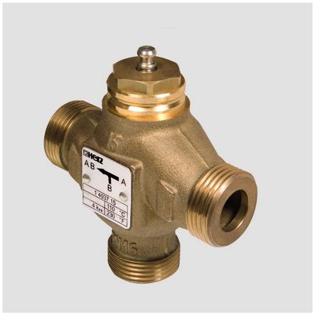
7 Hydraulic circuits for differential pressure connections in heating systems Various control-related circuits require a differential pressure at the distributor. To size the control valves correctly the differential pressure must be known, otherwise the control valves will be incorrectly dimensioned. Four basic circuit arrangements come into consideration with differential pressure connections. Throttle circuit With this form of hydraulic circuit the adjustment is made by throttling the flow rate. In this case, the control valves take over the task of changing the flow rate in the control circuit, e.g. to influence the thermal output of a heat exchanger. 6 Features: Water volume variable on both the distributed heat and consumer sides. Temperature on the distribution heat side constant (depending on the central temperature regulation) and constant on the consumer side. Output is regulated by altering the flow rate. 3 TI TI Benefits: This produces good diversity and is therefore suitable for condensing boiler and distributed heat systems. 2 Fig. 2: throttle circuit 1 pv psrv H 5 Pos Designation Article no. 1 Circuit regulating valve Mixing valve with drive Heating control Drawbacks: With several throttle circuits in the piping network the pump operating point is displaced by the change in valve travel and the associated pressure change. The pressure difference which occurs has an influence on individual consumers. The return flow control valve keeps the pressure constant and limits the flow rate. This guarantees reliable control without any influence. Throttle circuits are used wherever low return temperatures and variable flow rates are required. The thermal behaviour features decreasing return temperatures with a decreasing load. Isolation valve Strainer Temperature sensor DP Overflow valve 00 Table 2: throttle circuit 7
8 Specifically this circuit is to be found: In the distribution of district heating plants In connections to buffer storage, and also In integration of the consumer network with condensing boiler systems Further areas of use are: Zone control in radiator and underfloor heating systems with supply temperature regulated by the outdoor temperature and also for Small supplementary heaters and heat exchangers of all sizes Sizing example Q = 70 kw t V = 90 C t R = 50 C p L = 10 kpa H = 30 kpa = Q = c. (t V - t R ) = = 150 l/h.19. (90-50)! The pipe size depends on the pipe material and the permissible pipe friction. Requirement 1: p v p L (the differential pressure via the control valve must be greater than or equal to the differential pressure via the consumer). Step 1: Calculation of the minimum available differential pressure: Requirement 2: H H min (the available differential pressure at the distributor must be bigger than or equal to the required minimum differential pressure) H min = p V,min + p L + p SRV + p Ab + p Schmu! p SRV minimum 3 kpa The kv s values for size DN 25 were used to determine the pressure loss via the shutoff valve (115) and the strainer (111) mesh size. H min = = 2.9 [kpa] Since ΔH = 30 kpa, requirement 2 is fulfilled. Step 2: Calculation of the theoretical kv value of the control valve: ( p V,min = 10 kpa) q s k v,theo = = = p v,min Step 3: Selection of the kv s value from the valve class. The 037 valves in question are the DN 15 valve with a kv s value of.0 and the DN 20 valve with a kv s value of 6.3. Generally it can be assumed that the smaller kv s value is selected to achieve the necessary pressure loss. If kv s = 6.3 p v = = = 5.7 kpa Kv s Requirement 1 was not fulfilled. If kv s =.0 p v = = = 1.1 kpa Kv s Requirement 1 was fulfilled. The control valve has a kv s value of.0 and the size DN 15 The valve authority is: p v а = = 1.1 = 0.7 H 30 The valve authority should be between 0.35 and 0.75 but may not be less than 0.25, otherwise the system becomes unstable. Step : The sizing of the circuit supply regulating valve 8
9 Determination of the differential pressure to be dissipated: p SRV = H - ( p V + p L ) = = 30 - ( ) = 5.9 kpa Determination of the kv value: k v,srv = = = p SRV The default setting for a 217 straight regulating valve of 1 size is 3.3. Diversion circuit (distribution circuit) This circuit is a variant of the throttle circuit. 6 3 TI TI 1b 2 5 H 1a Features: Application: Benefits: Drawbacks: Water volume constant on distributed heat system side, variable on consumer side. Temperature constant on distributed heat system side (depending on the central temperature control), constant on the consumer side. Output in the consumer circuit is regulated by altering the flow rate. Fan operated air heaters, cooling coils, zone regulation An outlet-regulated pump is not required on the distributed heat side due to the constant flow rate. The differential pressure does not change and the individual consumers do not influence one another. The temperature at the consumer is always the same as the distributed heat temperature The hydraulic advantages of this circuit are the constant quantity of heating medium in the distributed heating circuit which means that output-regulated pumps are not required. The authority of the control valve depends only on the load, i.e. the three-port valve is installed independently of the distribution network since there is no interaction. The disadvantage of the diversion circuit is that the temperature at the consumer is always the maximum temperature of the distribution system supply and it is not possible to make use of any separate temperature level between the distributed heat and consumer circuits. Furthermore, installation is unsuitable and not permitted for buffer storage, condensing boiler systems and distributed heating systems, since warm supply medium is always mixed with the return valve and raises the return flow temperature during partial load operation. The rapid availability of hot distributed heat medium has large control-related benefits for the consumer. Constant-flow operation of the energy source, heat or cold generator, also has a control-related and also a partial operationally related benefit. From an energy efficiency point of view, however, the constant flow rate in the distributed heat circuit also brings a disadvantage with it since no pump energy can be saved. Fig. 3: Diversion circuit Pos Designation Article no. 1 Circuit regulating valve Mixing valve with drive Heating control Isolating valve Strainer Temperature sensor 7793 Table 3: diversion circuit 9
10 Sizing example Q = 0 kw t V = 6 C t R = 12 C p L = 25 kpa H = 70 kpa = Q = c. (t V - t R ) = = ~ 5730 l/h.19. (12-6)! The pipe size depends on the pipe material and the permissible pipe friction Requirement 1: p v p L (The differential pressure via the control valve must be greater than or equal to the differential pressure via the consumer) Step 1: Calculation of the minimum available differential pressure: Requirement 2: H H min (The available differential pressure at the distributor must be bigger than or equal to the minimum required differential pressure) H min = p V,min + p L + p SRV + p Schmu! p SRV minimum 3 kpa The kv s values for the DN 0 size were used to determine the pressure loss via the shutoff valve (115) and the strainer (111) mesh size. H min = = 53.8 [kpa] Since ΔH = 70 kpa, requirement 2 is fulfilled. Step 2: Calculation of the theoretical kv value of the control valve: ( p V,min = 25 kpa) k v,theo = = = p v,min Step 3: Selection of the kv s value from the valve class. The 037 valves in question are DN 25 valves with a kv s value of 10.0 and the DN 32 valve with a kv s value of 16. Generally it can be assumed that the smaller kv s value is selected to achieve the necessary pressure loss. if kv s = 16 p v = = = kpa Kv s Requirement 1 was not fulfilled. If kv s = 10 p v = = = 32.8 kpa Kv s Requirement 1 was fulfilled. The control valve has a kv s value of 10 and a size of DN 25 The valve authority is: p V а = = 32.8 p = 0.57 L + p V The valve authority should be between 0.35 and 0.75 but must not be below 0.25, otherwise the system becomes unstable. Step : The sizing of circuit supply regulating valve 1a in the return flow. Determination of the differential pressure to be dissipated: p SRV 1a = H - ( p V + p L + p Schmu ) = = 70 - ( ) = 11. kpa Determination of the kv value: k v,srv 1a = = = p SRV
11 The default setting for a 217 straight regulating DN 0 valve is.8. Step 5: Bypass sizing: Should the consumer not collect any output it must be possible to divert the entire mass flow via the bypass. Requirement 3: p SRV 2 = p L Requirement : q Bypass = The kv value of the valve in the bypass can be determined with these requirements. q Bypass k v,srv 1b = = = p SRV The default setting for a 217 straight regulating valve of DN 0 size is.0. Injection switching with two port valve Pos Designation Article no. 1 Circuit regulating valve Control valve with drive Heating control Isolation valve Strainer Outdoor temperature sensor Non-return valve DP Overflow valve 00 Table : Injection circuit with two port valve Features: Application: Benefits: Distributed heat system-side water volume variable and consumer-side constant. Consumer temperature variable. radiator systems, underfloor heating, fan operated air heaters, low-temperature heating. For systems with low return temperatures (distributed heating systems, condensing boiler systems), different temperature levels for distributed heat and consumer sides (e.g. 5 C and 90 C). Unlike with throttle circuits, the water volume in the consumer system in this system is constant. Drawbacks: To size the control valve the differential pressure must be known, there is a frost risk for preheating radiators in the case of long pipe runs. 1a Sizing example Q = 25 kw t V = 5 C t R = 35 C H = 25 kpa t primär = 70 C 5 2 1b q p = Q = c. (t p - t R ) = = 61 l/h.19. (70-35) 8 Fig. : Injection circuit with two port valve 11
12 ! The pipe size depends on the pipe material and the permissible pipe friction. = Q = c. (t V - t R ) = = 218 l/h.19. (5-35) Step 3: Sizing of circuit regulating valve 1a in the supply circuit. Determination of the differential pressure to be dissipated: p SRV 1a = H - p V = = 10.3 kpa Determination of the kv value: q p k v,srv 1a = = = p SRV Requirement 1: p v H (The differential pressure via the control valve must be greater than or equal to the differential pressure via the distributor) Step 1: Calculation of the theoretical kv value of the control valve: ( p V,min = 25 kpa) k v,theo = = = pv,min Step 2: Selection of the kvs value from the valve class. The 7762 valves in question are the DN 10 valve with a kv s value of 1.0 or 1.6. A larger value can be selected here. The remaining differential pressure is dissipated via circuit control valve 2. The required 10.3 kpa are dissipated via the circuit regulating valve. The default setting for a 217 straight regulating valve of DN 15 size is 2.9. Step : Sizing of circuit regulating valve 1b: Circuit regulating valve 1b should be sized with a nominal pressure loss of 3 kpa. k v,srv 1b = = = p stad The default setting for a 217 straight regulating valve of DN 32 size is.3. If kv s = 1.6 q p p v = = = 1.7 kpa Kv s The control valve has a kv s value of 1.6 and a size of DN 10. The valve authority is: p V а = = 1.7 = 0.59 H 25 The valve authority should be between 0.35 and 0.75 but must not be less than 0.25, otherwise the system is unstable. 12
13 Injection circuit with three-port valve With this hydraulic circuit, the volume flows in the distributed heat circuit and the consumer circuit are constant b Benefits: Drawbacks: Excellent controllability due to the constant consumer-side flow rate. Permanent return temperature increase, and therfore this in not suitable for district heating or condensing boilers. The benefits of this circuit lie in the low or totally negligible dead time as hot water is permanently available at the control valve. This characteristic is exploited with the installation of heating coils where large quantities of energy are required quickly. A further, already discussed benefit is the valve authority of almost 1, since there is almost no resistance in the variablevolume circuit. 5 1a 2 8 Sizing example Q = 90 kw t V = 75 C t R = 55 C H = 0 kpa T primär = 90 C Fig. 5: Injection circuit with three-port valve Pos Designation Article no. 1 Circuit regulating valve Mixing valve with drive Heating control Isolation valve Strainer Outdoor temperature sensor Non-return valve DP Overflow valve 00 q p = Q = c. (t p - t R ) = = 2209 l/h.19. (90-55)! The pipe dimension depends on the pipe material and the permissible pipe friction. = Q = c. (t V - t R ) = = 3866 l/h.19. (75-55) Table 5: Injection circuit with three-port valve Features: Application: Water volume in both distributed heat circuit and consumer sides constant. Consumerside temperature variable Radiator systems, low-temperature systems with almost equal distributed heat and consumer temperatures, fan operated air heaters, if the differential pressure is not known. 13
14 Requirement 1: p v > 3 kpa Step 1: Calculation of the theoretical kv value of the Control valve: k v,theo = = = p v,min Step 2: Selection of the kv s values from the valve class. The 037 valves in question are the DN 32 valve with a kv s value of 16 and the DN 0 valve with a kv s value of 25 If kv s = 25 p v = = = 2. kpa Kv s If kv s = 16 p v = = = 5.8 kpa Kv s The control valve has a kv s value of 16 and a size of DN 32. The valve authority is p V а = = 5.8 p = 1 v 5.8 Step 3: The sizing of circuit regulating valve 1a in the supply flow Determination of the differential pressure to be dissipated: p SRV 1a = H - p V = = 3.2 kpa Determination of the kv value: q p k SRV 2 = = = p SRV The default setting for a 217 straight regulating valve of DN 0 size is 3.0. Step : Sizing of circuit regulating valve 1b in the Return flow Circuit control valve 1b should be sized with a nominal pressure loss of 3 kpa k SRV 1b = = = p SRV The default setting for a 217 straight regulating valve of DN 0 size is 5.8. Step 5: Sizing of the bypass The bypass must be able to accept the entire consumer water volume. (The variable-volume circuit is limited to the bypass) 1
15 Hydraulic circuits for differential pressure-free connections in heating systems Various control-related circuits permit no differential pressure at the distributor. With these circuits, it must be taken into account that each consumer requires its own pump, even those with low power ratings. Two basic circuits come into consideration for differential pressure-free circuits. Hydraulic circuits for differential pressure-free connections and pressureless hydraulically separated distributors. Practice has shown that the hydraulic separation of heat generation and heat consumption circuits is beneficial. The use of a hydraulic separator ensures constant conditions on the consumer side despite strongly varying flow rates on the heat generation side. This creates improved conditions for the overall behaviour of the system. Mixing circuit In contrast to the diversion circuit this hydraulic circuit works with a variable water volume on the distributed heat side and a constant volume of heating medium in the consumer circuit. The mixing circuit for the consumer is controlled by a variable-temperature and constant-volume control. This form of hydraulic circuit is the most widespread circuit in heating technology as it is very simple to achieve. 1 TI 7 TI Pos Designation Article no. 1 Circuit regulating valve Three-port valve with drive Heating control Isolation valve Strainer Temperature sensor Outdoor temperature sensor Non-return valve 2622 Table 6: Mixing circuit Features: Distributed heat-side water volume variable, constant on consumer side, distributed heatside temperature variable. TI 5 2 Application: Benefits: Radiator systems, fan operated air heaters Excellent controllability due to the constant consumer-side flow rate. Fig. 6: Mixing circuit 15
16 Drawbacks: The distributed heat-side and consumer-side temperature level must be almost equal. This means that a low-temperature system cannot be coupled to a high-temperature system. No distributed heat-side differential pressure is permitted. The control valve in the return flow limits the flow rate. Sizing example Q = 20 kw t V = 80 C t R = 60 C p L = 25 kpa = Q = c. (t V - t R ) = = 860 l/h.19. (80-60)! The pipe size depends on the pipe material and the permissible pipe friction. The data is taken from the calculated system Step 1: Calculation of the theoretical kv value of the control valve: ( p V,min = 3 kpa) k v,theo = = = p v,min Step 2: Selection of the kv s value from the valve class. The 037 valves in question are the DN 20 valve with a kv s value of 6.3 and the DN 15 valve with a kv s value of. Normally it can be assumed that the smaller kv s -value is selected to achieve the necessary pressure loss. If kv s = 6.3 p v = = = 1.86 kpa Kv s p v < 3 kpa! If kv s =.0 pv = = =.62 kpa Kv s p v > 3 kpa The control valve has a kv s value of.0 and a size of DN 15. The distributed heat circuit contains two shutoff valves (115 3/ ) and a strainer (111, 3/ mesh size 0.75 mm). The valve authority is p V а = = p v + 2. p Ab + p Schmu.62 = = The pressure loss in the mixing valve must be additionally provided by the pump. Step 3: Sizing of the circuit regulating valve to 3 kpa k v,srv = = = p SRV The default setting for a 217 straight regulating valve with a size of DN 20 is 3.7. Dual mixing circuit Another form of mixing circuit is the mixing circuit with fixed bypass which is used in applications where differences occur in the temperature levels of the distributed heat and consumer circuits. This time, the bypass is in the consumer circuit before the control valve via which a permanent quantity of return medium flows regardless of the three-port valve setting. This circuit is in widespread use with underfloor heating and also condensing boiler, storage and distributed heat systems. Mixing circuits are constructed with three-port valves and direct distributed heat-side connection to the heat generator. 16
17 1a 1b Drawbacks: Sizing example The distributed heat-side supply temperature must be higher than the consumer-side supply temperature. No distributed heat-side differential pressure is permitted. If a distributor under pressure is used, a pressureless mixing circuit must be used. Fig. 7: Dual mixing circuit Pos Designation Article no. 1 Circuit regulating valve Three-port valve with drive Heating control Isolation valve Strainer Temperature sensor Outdoor temperature sensor Non-return valve 2622 Table 7: Dual mixing circuit 2 5 Q = 0 kw t V = 5 C t R = 35 C t P = 70 C p L = 25 kpa q p = Q = c. (t p - t R ) = = 982 l/h.19. (70-35)! The pipe dimension depends on the pipe material and the permissible pipe friction. = Q = c. (t V - t R ) = = 337 l/h.19. (5-35) Step 1: Calculation of the theoretical kv value of the control valve: ( p V,min = 3 kpa) Features Application: Benefits: Distributed heat-side water volume constant, consumer-side volume constant. Consumerside temperature variable. Low-temperature heating with different distributed heat and consumer temperatures. Especially for underfloor heating systems in a high-temperature system. The control valve authority is almost 1 when used with pressureless or low-pressure distributors (i.e. good controllability). Can be used to connect low-temperature heating (e.g. 5 C to 90 C). q p k v,theo = = = p v,min Step 2: Selection of the kv s value from the valve class. The 037 valves in question are the DN 20 valve with a kv s value of 6.3 and the DN 15 valve with a kv s value of. Normally it can be assumed that the smaller kv s value is selected to achieve the necessary pressure loss. 17

18 If kv s = 6.3 q p p v = = = 2. kpa Kv s p v < 3 kpa If kv s =.0 q p p v = = = 6.0 kpa Kv s p v > 3 kpa! The control valve has a kv s value of.0 and a size of DN 15. The valve authority is: p V 6,0 а = = = 0.5 p v + p SRV The pressure loss in the mixing valve must be additionally provided by the pump. Step 3: Sizing for circuit regulating valve 1a is 3 kpa k v,srv 1a = = = p SRV The default setting for a 217 straight regulating valve with a size of DN 0 is 5.3 Step : Sizing of the bypass The bypass flow rate is calculated from: q Bypass = - q p = = 255 [l/h] Circuit control valve 1b is sized to the control valve s pressure loss (7.6 kpa) q Bypass k v,srv 1b = = = p SRV The default setting for a 217 straight regulating valve with a size of DN 32 is.0. Heating systems with a hydraulic switch. Heat generators connected in parallel. Static regulation of the circuits. First consumer per circuit with static regulation, consumers two to four with mixing circuit. 18
 systems, 1999 Control and hydraulic circuits in heating and ventilation systems, VDI Verlag, 3.9.-.9.1992 Roos, H.")
19 Bibliography & table of figures OENORM H 512, Technical equipment for buildings; hydraulic circuits for heating installations, 1990 VDI 2073, Hydraulic circuits in heating, ventilation and airconditioning (HVAC) systems, 1999 Control and hydraulic circuits in heating and ventilation systems, VDI Verlag, Roos, H., Hydraulics for hot water systems, Oldenbourg Verlag Munich, 1999 Fig. 1: Quick selection...6 Fig. 2: Throttle ciurcuit... 7 Fig. 3: Diversion circuit... 9 Fig. : Injection circuit with 2 port valve Fig. 5: Injection circuit with 3-port valve Fig. 6: Mixing circuit Fig. 7: Dual mixing circuit Table 1: Overview of circuits... 5 Table 2: Throttle circuit... 7 Table 3: Diversion circuit... 9 Table : Injection circuit with 2 port valve Table 5: Injection circuit with 3-port valve Table 6: Mixing circuit Table 7: Dual mixing circuit...17 This brochure is for information only. It simply contains recommendations by Herz-Armaturen Ges.m.b.H and no guarantee is implied. No responsibility is taken for the accuarcy of the information provided. This brochure is to be used as a guideline only. We reserve the right to make changes in the event of technical advancements The illustrations are understood to be symbolic representations and may therefore vary visually from the actual products. Any colour variations are dependent upon the printing technology used. Products may also vary according to the country. We reserve the right to make changes to technical specifications and functions. Please contact your nearest branch of HERZ with any questions. System separation with heat exchangers. Automatic control before the heat exchanger and static control after it. Circuits two and three with dynamic control. First consumer with throttle circuit. Consumers two to four have an injection circuit with two port valve. 19
20 HERZ Valves UK Progress House, Moorfield Point Moorfield Road, Slyfield Industrial Estate Guildford, Surrey GU1 1RU Tel.: + (0) , Fax: + (0) sales@herzvalves.com International Headquarter HERZ Armaturen GmbH Richard-Strauss-Strasse 22, A-1230 Vienna Tel.: +3 (0) , Fax: +3 (0) office@herz.eu HKLS-EN
HERZ-Connect 4 / Compact Connect 4 & Commissioning Centres
 www.herz.eu HERZ-Connect 4 / Compact Connect 4 & Commissioning Centres Simple and cost efficient methodes of thermal units control 1 Connect 4.indd 1 17.11.2015 10:31:20 HERZ- Connect 4 HERZ Connect-4
HERZ-Pressure Independent Control Valves
 www.herz.eu HERZ-Pressure Independent Control Valves 1 ! HERZ 46 SMART in fully open position HERZ 46 SMART in operation; due to the pressure relief, very low actuating forces and differential pressures
Hydraulics in building systems
 Hydraulics in building systems Building Technologies s Contents 1. Hydraulic circuits 2. Hydraulic characteristics 3. Sizing the controlling elements 1.1 Key components of a hydraulic plant 5 1.2 The different
Hydraulics in building systems. siemens.com/buildingtechnologies
 Hydraulics in building systems siemens.com/buildingtechnologies Contents 1 Hydraulic circuits... 6 1.1. Key components of a hydraulic plant... 6 1.2. Different hydraulic circuits... 7 1.3. Consumers with
HERZ-Motorised flow controler
 HERZ-Motorised flow controler Control and regulating valve Data sheet 4006 SMART, Issue 0516 Dimensions in mm 4006 M 4006 R M R Order number DN G L L1 B B1 H without Actuator H with Actuator H1 1 4006
3-Port Seat Valves with Male Thread, PN 16
 6 3-Port Seat Valves with Male Thread, PN 6 VXG ronze CC9K (Rg5) valve body DN 5DN 0 k vs 02525 m 3 /h Flat sealing connections with external thread G to ISO 228/ Sets of ALG 3 screwed fittings with threaded
Back pressure safety valves
 1/12 Back pressure safety valves 1. Introduction 2. Safety valve in the installation 3. Influence of back pressure on functioning behaviour 4. Limits of admissible back pressure (without metal bellow)
3-port seat valves PN16 with flanged connection
 4 430 Acvatix 3-port seat valves PN16 with flanged connection VXF40.. Grey cast iron EN-GJL-250 valve body DN 15 150 k vs 1.9 315 m 3 /h Can be equipped with SQX.. electromotoric or SKD..-, SK..- and SKC..-
3-port seat valves PN40 with flanged connection
 4 482 DN 15 and DN 25 DN 40 150 Acvatix 3-port seat valves PN40 with flanged connection VXF61.. Cast steel GP240GH valve body DN 15...150 k vs 1.9...300 m 3 /h Can be equipped with SKD.., SK.. and SKC..
3-port seat valves, external thread, PN16
 4 464 3-port seat valves, external thread, PN6 VXG44.. ronze CC49K (Rg5) valve body DN 5..DN 40 k vs 0.25..25 m 3 /h Flat sealing connections with external thread G to ISO 228- Sets of ALG..3 screwed fittings
Written By : Simon Teo B. ENG (HONS)
") Written By : Simon Teo B. ENG (HONS) The Ultimate Control Valves Used in Hydronic HVAC System FlowCon International pressure independent flow control valves () are changing the way control valves function
Written By : Simon Teo B. ENG (HONS) The Ultimate Control Valves Used in Hydronic HVAC System FlowCon International pressure independent flow control valves () are changing the way control valves function
Components of Hydronic Systems
 Valve and Actuator Manual 977 Hydronic System Basics Section Engineering Bulletin H111 Issue Date 0789 Components of Hydronic Systems The performance of a hydronic system depends upon many factors. Because
2-port and 3-port terminal unit valves PN16
 4 847 2-port valves VVP47..(S) 3-port valves VXP47.. cvatix 2-port and 3-port terminal unit valves PN16 3-port valves with bypass VMP47..(S) VVP47..(S) VXP47.. VMP47..(S) ronze valve body CC491K (Rg5)
Circuit Regulating Valve STRÖMAX GF
 Circuit Regulating Valve STRÖMAX - GF Circuit Regulating Valve for differential pressure measurement, with test points, flanged version Data sheet for GF Issue 0 GF STRÖMAX GF with test points H H D L.
2-port and 3-port ball valves PN 40
 s 4 211 VAI61.. VBI61.. ACVATIX TM 2-port and 3-port ball valves PN 40 with internally threaded connections VAI61.. VBI61.. Brass UNS C35330 (DZR) ball valve body DN 15...50 k vs 1...63 m 3 /h Internally
Starting up hydraulic systems
 General / Installation A hydraulic system that operates economically, safely, and trouble-free requires careful planning, as well as proper installation and start-up. Conscientious maintenance has a considerable
2-Port and 3-Port Zone Valves PN 16
 4 842 2-port valves VVI4615 to VVI4625 3-port valves VXI4615 to VXI4625 2-port valves VVS4615 to VVS4625 3-port valves VXS4615 to VXS4625 2-Port and 3-Port Zone Valves PN 16 VVI46 VXI46 VVS46 VXS46 Hot-pressed
2-way and 3-way globe valves
 2-way and 3-way globe valves Table of Contents Background Project planning 2 Flow characteristics 2 Principles of flow control 3 ydraulic circuits 4 Design and dimensioning Cavitation diagrams 5 Design
2-Port and 3-Port Zone Valves PN 16
 4 842 2-port valves VVI46.15 to VVI46.25 3-port valves VXI46.15 to VXI46.25 2-Port and 3-Port Zone Valves PN 16 VVI46... VXI46... Hot-pressed brass valve body (EN1982); VXI46.25T: bronze CC491K (Rg5) max.
3-port seat valves PN16 with flanged connection
 4 440 Acvatix 3-port seat valves PN16 with flanged connection VXF41.. Grey cast iron EN-GJL-250 valve body DN 15...150 k vs 1,9...300 m 3 /h Can be equipped with SAX..-electromotoric or SKD..-, SK..- and
2-port and 3-port valves with T-bypass PN 16
 4 854 2-port valves 3-port valve with T-bypass CVTIX 2-port and 3-port valves with T-bypass PN 16 VVP45..S VMP45..S ronze CC499K valve body DN 10 and DN 15 k vs 0.63 2.5 m 3 /h Externally threaded connections
2-Port Seat Valves with Flange, PN 25
 4 7 2-Port Seat Valves with Flange, PN 25 VVF52... Nodular cast iron EN-GJS-400-8-LT valve body DN 5...40 k vs 0.6...25 m /h Can be equipped with SQX- electromotoric or SKD...- or SKB...- electrohydraulic
4017 M HERZ Dimensions in mm
 HERZ STRÖMAX 4017 Commissioning valve with integral fixed orifice plate Control valve for chilled and hot water systems in buildings Data sheet for 4017, Issue 0716 Dimensions in mm H2 H1 L1 L2 D 4017
2-port seat valves PN25 with flanged connection
 4 373 Acvatix 2-port seat valves PN25 with flanged connection VVF52.. Nodular cast iron EN-GJS-400-8-LT valve body DN 5...40 k vs 0.6...25 m 3 /h Can be equipped with SAX..-electromotoric or SKD..- or
3-Port Seat Valves with Male Thread, PN 16
 4 463 3-Port Seat Valves with Male Thread, PN 16 VXG41 Use Media Bronze CC491K (Rg5) valve body DN 15DN 50 k vs 1640 m 3 /h Flat sealing connections with external thread G B to ISO 228/1 Sets of ALG 3
2-port seat valves PN16 with flanged connection
 4 330 Acvatix 2-port seat valves PN16 with flanged connection VVF40.. Grey cast iron EN-GJL-250 valve body DN 15...150 k vs 1.9...315 m 3 /h Can be equipped with SAX..-electromotoric or SKD..-, SKB..-
3-port seat valves PN10 with flanged connection
 4 420 cvatix 3-port seat valves PN10 with flanged connection VXF31.. Grey cast iron EN-GJL-250 valve body DN 15 150 k vs 2.5 315 m 3 /h Can be equipped with SX..-electromotoric or SKD..-, SK..- and SKC..-
3-port seat valves PN6 with flanged connection
 4 410 cvatix 3-port seat valves PN6 with flanged connection VXF21.. Grey cast iron EN-GJL-250 valve body DN 25...100 k vs 1.9...160 m 3 /h Can be equipped with SQX.. electromotoric or SKD..-, SK..- and
Modulating Control Valve PN 16 with Magnetic Actuator
 4 74 Modulating Control Valve PN 6 with Magnetic Actuator for brine circuits, hot water, steam or media containing mineral oils (MK FX NP) MK FX N MK FX NP Fast positioning time (< s) High-resolution stroke
Technote. Frese OPTIMA - Pressure independent control & balancing valve. Application. Features. Benefits.
 Page 1 of 12 Application pressure independent control valve (PICV) is used in heating and cooling systems in applications with Fan Coil Units, Air Handling Units or other terminal unit applications. provides
VPI45..Q with pressure test points. Combi valves, PN 25
 4 853 VPI45.. VPI45..Q with pressure test points ACVATIX Combi valves, PN 25 for rooms, zones, air handling units as well as small to medium heating, ventilation and airconditioning systems VPI45.. VPI45..Q
Product Sheet Pre-Fabricated Flushing Bypass Assembly for Plant Applications Hero Plant DN15-150
 Product Sheet Pre-Fabricated Flushing Bypass Assembly for Plant Applications Hero Plant DN15-150 Description Hero Plant is a pre-fabricated, flushing bypass arrangement for balance, control, isolation,
Fan-coil valves Series
 Fan-coil valves Series 11-11 - 411 Main features Complete range in the following versions : -way - DN: 1/, /4, 1 -way - DN: 1/, /4, 1 -way with 4 ports - DN: 1/, /4 - The -way version and the -way versions
Connection. k VS value m 3 /h
 76.122/1 VUP: Pressure-relieved through flanged valve, PN 25 How energy efficiency is improved Thanks to the pressure compensation, savings can be made with the actuator. Precision and reliability go without
Three-port slipper valves PN10, female-threaded
 4 232 SERIES 02 Three-port slipper valves PN10, female-threaded VBI31.. Three-port slipper valves, PN10, female-threaded Grey cast iron EN-GJL-250 DN 20 40 k vs 6.3...25 m 3 /h Angle of rotation 90 Female-threaded
2-Port Seat Valves with Flange, PN 25
 OEM 2-Port Seat Valves with Flange, PN 25 VVF52...E Spheroidal cast iron EN-GJS-400-8-LT valve body DN 5...40 k vs 0.63 25 m 3 /h Can be equipped with SQX E- motoric or SKD E- or SKB - electrohydraulic
Product range Solex Technical data and dimensioning. 5 Years
 Qualität made in Germany Product range Solex Technical data and dimensioning Quality made in Germany 5 Years Handwerkergarantie m anufacturer s warranty Product range Solex Dimensioning High-Flow system
Elbtalwerk GmbH. Universität Karlsruhe Elektrotechnisches Institut. Switched Reluctance Motor. Compact High-torque Electric Motor. Current.
 Elbtalwerk GmbH Switched Reluctance Motor Compact High-torque Electric Motor Current B1 Winding A1 D4 C1 C4 Pole D1 Rotation B4 A2 Rotor tooth Shaft A4 B2 Field line D3 C2 C3 D2 Stator A3 B3 Cooling air
FLOW RATE STATIC BALANCING Valves for radiators
 Balancing part 3 TECHNICAL FOCUS FLOW RATE STATIC BALANCING Valves for radiators The valves for radiators equipped with pre-setting device play a very important role in balancing the heating systems circuits.
Tehnical paper. Technical paper Title. Hydraulic balance in. Title. a district heating system. Author(s), Danfoss. heating.danfoss.
, Danfoss. heating.danfoss.") Tehnical paper Technical paper Title Hydraulic balance in Title a district heating system Author(s), Danfoss Herman Boysen Published at... and Jan Eric Thorsen heating.danfoss.com districtenergy. districtenergy.danfoss.com
Tehnical paper Technical paper Title Hydraulic balance in Title a district heating system Author(s), Danfoss Herman Boysen Published at... and Jan Eric Thorsen heating.danfoss.com districtenergy. districtenergy.danfoss.com
VDL : 2-way regulating valve for dynamic hydronic balancing, PN 25, Valveco compact
 Product data sheet 9.1 7.003 VDL 010...00: 2-way regulating valve for dynamic hydronic balancing, PN 2, Valveco compact How energy efficiency is improved Automatic dynamic hydronic balancing with the SAUTER
HERZ Electronic room thermostat analog and digital
 Dimension in mm 3 F799 11-3 F799 14 HERZ Electronic room thermostat analog and digital Data sheet for F799, Issue 0317 3 F799 15 3 F799 18 Mounting plate Page 1 Technical data 3 F799 11-14 3 F799 15-18
Series 02: DN40 and DN50 Series 01: DN Three-port slipper valves PN6
 4 241 Series 02: DN40 and DN50 Series 01: DN 65...150 Three-port slipper valves PN6 VBF21... Three-port slipper valves, PN6, flanged Grey cast iron EN-GJL-250 DN 40...150 k vs 25...820 m 3 /h Angle of
VPI45.. VPI45..Q. Combi valves, PN 25. Building Technologies. VPI45..Q with pressure test points ACVATIX
 4 853 VPI45.. VPI45..Q with pressure test points ACVATIX Combi valves, PN 25 for rooms, zones, air handling units as well as small to medium heating, ventilation and air-conditioning systems VPI45.. VPI45..Q
3-Port Seat Valves with Flange, PN 6
 4 410 3-Port Seat Valves with Flange, PN 6 VXF21... Grey cast iron EN-GJL-250 valve body DN 25... k vs 1.9...160 m 3 /h Can be equipped with SQX... electromotoric or SKD...-, SK...- and SKC...- electrohydraulic
CALEFFI. Pre-assembled distribution manifolds for. heating and air-conditioning systems. 663 series 01065/18 GB. replaces dp 01065/06 GB.
 Pre-assembled distribution manifolds for heating and air-conditioning systems 663 series FM 21654 003 065/18 GB replaces dp 065/06 GB Function The pre-assembled distribution manifolds are designed to optimise
3-Port Seat Valves with Flange, PN 10
 4 420 3-Port Seat Valves with Flange, PN 10 VXF31... Grey cast iron EN-GJL-250 valve body DN 15 150 k vs 2.5 315 m 3 /h Can be equipped with SQX... electromotoric or SKD...-, SK...- and SKC...- electrohydraulic
VPI45..Q with pressure test points. Combi valves, PN 25
 4 853 VPI45.. VPI45..Q with pressure test points ACVATIX Combi valves, PN 25 for rooms, zones, air handling units as well as small to medium heating, ventilation and air-conditioning systems VPI45.. VPI45..Q
2-port ball valves with flanged connection, PN25
 s 4 120 ACVATIX 2-port ball valves with flanged connection, PN25 VAF51.. Gray cast iron EN-GJL-250 (HT250) valve body DN 65...150 k vs 63...360 m 3 /h Angle of rotation 90 Flange connection to ISO 7005-2
Volkswagen DCC Adaptive Chassis Control - Design and Function DCC Adaptive Chassis Control. Basics of the damping system
 Volkswagen DCC Adaptive Chassis Control - Design and Function DCC Adaptive Chassis Control The rule for suspension systems has always been that increasing sportiness compromises the ride. In this new system
Resolair 64 and 68. Comfort air conditioning unit with highly efficient regenerative heat storage packages. AIR VOLUME FLOW: 3,900 23,100 m³/h
 Comfort air conditioning unit with highly efficient regenerative heat storage packages 68 10 01 - simplified illustration Automatically selects the most economical operating mode! 64 and 68 AIR OLUME FLOW:
BUD: 3-way flanged valve, PN 6 (pn.)
") Product data sheet 76.111 BUD: 3-way flanged valve, PN 6 (pn.) How energy efficiency is improved Efficient use in continuous control systems Features Continuous control of cold and hot water in closed
Product data sheet 76.111 BUD: 3-way flanged valve, PN 6 (pn.) How energy efficiency is improved Efficient use in continuous control systems Features Continuous control of cold and hot water in closed
VE-S_15-32 Pressure Independent Balancing & Control Valves
 Page 1 of 9 VE-S_15-32 Pressure Independent Balancing & Control Valves (PIBCV) is used in heating and cooling systems in applications with Fan Coil Units, Chilled Beams or other terminal unit applications.
76.116/1. BUE: Flanged three-way valves, PN 16/10. Sauter Components
 76.116/1 BUE: Flanged three-way valves, PN 16/10 How energy efficiency is improved Accurate control with high reliability. Areas of application Continuous control of cold/hot water, air and low-pressure
Product Sheet Pre-Fabricated Flushing Bypass Assembly for Terminal Applications Mini-Flush 40
 Product Sheet Pre-Fabricated Flushing Bypass Assembly for Terminal Applications Mini-Flush 40 Description Miniflush40 is a pre-fabricated, flushing bypass arrangement for balance, control, isolation, and
VCL : 2-way regulating valve for dynamic hydronic balancing, PN 16, Valveco
 Product data sheet 6.1 57.001 VCL 010 032: 2-way regulating valve for dynamic hydronic balancing, PN 16, Valveco How energy efficiency is improved Automatic dynamic hydronic balancing with the SAUTER Valveco
Automatic balancing valves ASV-PV DN (3rd gen.)
") Automatic balancing valves ASV-PV DN 50-100 (3rd gen.) Description / Application Partner valve ASV-PV DN 50 ASV-PV DN 65-100 MSV-F2 DN 50-100 ASV balancing valves are used for dynamic hydronic balance
Automatic balancing valves ASV-PV DN 50-100 (3rd gen.) Description / Application Partner valve ASV-PV DN 50 ASV-PV DN 65-100 MSV-F2 DN 50-100 ASV balancing valves are used for dynamic hydronic balance
Overview of types. Technical data
 Technical data sheet 6..S+NVFT24-MFT-E Globe valves, 2-way, with flange PN 16, actuator with emergency control function for closed hot water systems up to 150 C in district heating applications approved
Air Conditioning Clinic. HVAC System Control One of the Systems Series TRG-TRC017-EN
 Air Conditioning Clinic HVAC System Control One of the Systems Series TRG-TRC017-EN NO POSTAGE NECESSARY IF MAILED IN THE UNITED STATES BUSINESS REPLY MAIL FIRST-CLASS MAIL PERMIT NO 11 LA CROSSE, WI POSTAGE
Product bulletin for: ST2 Ball valves with two-way and three-way BSPP threaded fittings
 Product bulletin for: ST2 Ball valves with two-way and three-way BSPP threaded fittings ST2 Ball valves in conjunction with spring return and non-spring return VA-Actuators Developed for HVAC applications
2-port shutoff valves and 3-port changeover ball valves, PN 40, with internally threaded connection
 ACVATIX 2-port shutoff valves and 3-port changeover ball valves, PN 40, with internally threaded connection VAI60.., VBI60..L, VBI60..T VAI60.. VBI60..L VBI60..T For use in heating, ventilation, and air
COMFORT AIR CURTAIN. SensAir
 COMFORT AIR CURTAIN SensAir SensAir comfort air curtain A new wave in climate separation SensAir air curtains are the ideal solution for retailers and other end-users to combat the issue of climate separation
Technote. Frese OPTIMIZER - pressure independent 4-pipe coil control unit. Application. Benefits. Features.
 Page of 7 Application control unit, in conjunction with the associated hydraulic set provides a complete pressure independent balancing and control group for efficient and effective individual room or
VZ*19* VZ219E, VZ319E, VZ419E VZ219C, VZ319C, VZ419C
 VZ219E, VZ319E, VZ419E VZ219C, VZ319C, VZ419C SPECIFICATIONS Design PN16, Two-way, Three-way and Three-way with bypass (Linear operation) Function.... Normally Closed (A-AB). [Without actuator fitted]
Hot-film Air-mass Meter HFM 6
 Service Training Self-study Programme 358 Hot-film Air-mass Meter HFM 6 Design and Function Due to the further development of standards and laws for exhaust emissions in vehicles, components with improved
MRXBOX-VSC Visual System User Control Installation and Maintenance
 MRXBOX-VSC Visual System User Control Installation and Maintenance The EMC Directive 2014/30/EU The Low Voltage Directive 2014/35/EU 1.0 INTRODUCTION The MRXBOX-VSC is a user control from the Ecosmart
ACVATIX MiniCombiValves (MCV)
") 2 185 ACVATIX MiniCombiValves (MCV) Radiator valves featuring integrated differential pressure control for 2-pipe heating systems, fan coils and chilled ceiling systems VPD.. VPE.. Automatic flow limitation
2 185 ACVATIX MiniCombiValves (MCV) Radiator valves featuring integrated differential pressure control for 2-pipe heating systems, fan coils and chilled ceiling systems VPD.. VPE.. Automatic flow limitation
Series 02: DN40 and DN50 Series 01: DN Three-port slipper valves PN6
 4 241 Series 02: DN40 and DN50 Series 01: DN 65...150 Three-port slipper valves PN6 VBF21.. Three-port slipper valves, PN6, flanged Grey cast iron EN-GJL-250 DN 40...150 k vs 25...820 m 3 /h Angle of rotation
Two temperature sensors to protect against freezing and high head pressure in both the indoor evaporator and the outdoor condenser
 The ZC 107 Zone Control System was designed to provide the perfect comfort control within the home. At the same time it was designed to make an airconditioning system work more efficiently and thereby
Mounting and Operating Instructions EB 5894 EN. Electric control valves with jet pump. Flanged version of valve with jet pump
 Electric control valves with jet pump Type 3267/5824, Type 3267/5825, Type 3267/3374, Type 3267/3274 Pneumatic control valves with jet pump Type 3267-1, Type 3267-7 Flanged version of valve with jet pump
BQE: 3-way flanged valve, PN 16
 Ambient conditions 1) Operating temperature 2) -10...150 C Product data sheet 56.118 BQE: 3-way flanged valve, PN 16 How energy efficiency is improved Efficient use in continuous control systems Features
with electric actuators Feedwater control valve with pump spill back DN
 ARI-STEVI 453 with electric actuators Feedwater control valve with pump spill back DN 25-100 ARI-STEVI 453 Electric actuator ARI-PREMIO 2,2-15 kn ARI-PREMIO-Plus 2G 2,2-15 kn Enclosure IP 65 2 torque switches
Introduction to Johnson Controls Dampers
 Damper and Actuator Product Guide 268.1 Damper Engineering Section Product Bulletin Issue Date 1297 Introduction to Johnson Controls Dampers For over 100 years, Johnson Controls has been the industry leader
WG5Kxxx Modular DC-converter system
 Short description WG5Kxxx Modular DC-converter system General characteristics The modular DC converter system is useful for the DC coupling of various electrical components (sources, sinks, storages) with
Modulating control valve PN16 with magnetic actuator
 Modulating control valve PN with magnetic actuator for hot and chilled water with positioning control and position feedback MP80FY MP00FY Mixing or straight-through valves DN80 and DN00 with magnetic actuator
Type overview. R B2 en-gb subject to changes 1
 Technical data sheet R30..-..-..-B2 Characterised control valve, 6-way, Internal thread Two sequences (cooling/heating) with one 90 rotary actuator Switching or modulating control on the water side of
Variable Air Volume Dampers
 OVAV 2000 SERIES OPTIMA VAV DAMPERS Overview OPTIMA make Variable Air Volume (OVAV) box is a part of an Air Conditioning system. It is located inside the duct work. VAV Dampers are designed to control
Resin Impregnated Paper Bushing, Oil to Air, Type GSB Technical guide
 1ZSC000563-AAC en, Rev. 2 Resin Impregnated Paper Bushing, Oil to Air, Type GSB Technical guide This Technical Guide has been produced to allow transformer manufacturers, and their designers and engineers,
BUE: 3-way flanged valve, PN 16/10 (el.)
") Product data sheet 56.116 BUE: 3-way flanged valve, PN 16/10 (el.) How energy efficiency is improved Efficient use in continuous control systems Features Continuous control of cold and hot water in closed
Product data sheet 56.116 BUE: 3-way flanged valve, PN 16/10 (el.) How energy efficiency is improved Efficient use in continuous control systems Features Continuous control of cold and hot water in closed
ANALYSIS OF THE INFLUENCE OF OPERATING MEDIA TEMPERATURE ON FUEL CONSUMPTION DURING THE STAGE AFTER STARTING THE ENGINE
 ANALYSIS OF THE INFLUENCE OF OPERATING MEDIA TEMPERATURE ON FUEL CONSUMPTION DURING THE STAGE AFTER STARTING THE ENGINE Martin Beran 1 Summary: In Current increase in the automobile traffic results in
HERZ 7217 V. Integral Fixed Orifice Control Valve HERZ 7217 V. Data sheet 7217 V, Issue Size in mm. STRÖMAX Fig No DN L Lm Rp H SW kv kvs
 HERZ 7217 V Integral Fixed Orifice Control Valve Data sheet 7217 V, Issue 1011 Size in mm STRÖMAX Fig No DN L Lm Rp H SW kv kvs TS-V LF 1 7217 50 15 83 28,5 1/2 41 27 0,07-0,45 0,48 TS-V MF 1 7217 59 15
Two-port seat valves with male thread, PN16
 4 363 Two-port seat valves with male thread, PN6 VVG4... Two-port seat valves with male thread, PN6 Bronze Rg5 DN5... DN50 mm (½"... 2") k vs 0.63... 40 m 3 /h Stroke 20 mm Can be equipped with actuators
Air Cooler Industry AC-LN 8-14 / ACA-LN 8-11 / ACAF-LN 8-11
 Air Cooler Industry AC-LN 8-14 / ACA-LN 8-11 / ACAF-LN 8-11 Symbol General The AC-LN 8-14 air cooler series can be used in all areas where either oil or water-glycol is to be cooled with air. The coolers
BUN: 3-way valve with male thread, PN 16
 Product data sheet 7.1 56.101 BUN: 3-way valve with male thread, PN 16 How energy efficiency is improved Reliable actuation in efficient control systems Features Regulating valve free of silicone grease
HERZ PUMPFIX HERZ PUMPFIX. Datasheet 1 45XX XX, Issue Table of contents. Page 1. General information about HERZ PUMPFIX pump groups...
 Datasheet 1 45XX XX, Issue 0216 Table of contents General information about pump groups...2 Direct (1 4510 XX)...4 DN 20 DN 25 DN 32 Mix (1 4511 XX)...6 DN 20 DN 25 DN 32 Mix with bypass (1 4511 XX)...10
Example application for an supply air control with recirculated air addition. HVAC Application Note 3
 Example application for an supply air control with recirculated air addition HVAC Application Note 3 Version 14.03.2007 2 General Copyright 2007 by WAGO Kontakttechnik GmbH & Co. KG All rights reserved.
COMFORT AIR CURTAIN. SensAir
 COMFORT AIR CURTAIN SensAir SensAir comfort air curtain A new wave in climate separation SensAir air curtains are the ideal solution for retailers and other end-users to combat the issue of climate separation
Globe Valves. Technical Databook Version 1.2. Belimo Asia Pacific
 Globe Valves Technical Databook Version 1.2 Belimo Asia Pacific Contents Globe Valves Product Overview Max. Close-off Pressure - Globe Valve Series Globe Valve Actuators Product Overview 4 5 General Information
YARWAY NARVIK VEN-TEMP DESUPERHEATER MODEL 25
 Yarway covers requirements for Desuperheaters, pneumatic actuators, strainers with a wide range of models, sizes and materials to satisfy all the specifications of the power, pulp and paper industry and
Modulating control valves with magnetic actuators, PN 16
 4 461 Modulating control valves with magnetic actuators, PN 16 for drinking water, cold water and hot water systems, DVGW approved MXG461B.. Short positioning time (< 2 s), high resolution (1 : 1000) Selectable
SRK-COMBO. Return & Suction Filters Low Pressure Filter In-Tank up to 10 bar. Filter Elements Emergency Suction
 Return & Suction Filters Low Pressure Filter In-Tank up to 10 bar Technical Data Filter Elements Main Operating pressure up to 1000 kpa (10 bar). Static pressure testing up to 1500 kpa (15 bar). Back pressure
Open/close ball valves 2-port and changeover ball valves 3-port, PN40
 s 4 213 VAI60.. VI60..L VI60..T ACVATIX TM Open/close ball valves 2-port and changeover ball valves 3-port, PN40 with internally threaded connections VAI60.. VI60..L VI60..T rass UNS C35330 (DZR) ball
Circulators for heating and air-conditioning
 Circulators for heating and air-conditioning Can you think of a range of pumps offering you more in precision and convenience for your various projects? H kpa 600 Standardized circulators 200 100 Inline
Technische Information. Electronically controlled cooling. Reason for the development. Changes compared with the conventional cooling circuit
 1 Behr Hella Service GmbH, Schwäbisch Hall 8. April 2010 1-6 Electronically controlled cooling Reason for the development Perfect engine function also influences the engine s performance. In the case of
Tips & Technology For Bosch business partners
 Tips & Technology For Bosch business partners Current topics for successful workshops No. 05 Trucks Starters and starter systems Part 2 Moderately heavy commercial vehicles with diesel engines having a
Cooler Bellhousing KPV series
 Cooler Bellhousing KPV series» Dimensions acc. to VDMA 24 561» Rigid and noise damping versions in identical lengths» Easy replacement of rigid/dampened bellhousing acc. to VDMA 24 561» Optional combination
Modulating control valve PN16 with magnetic actuator
 Modulating control valve PN with magnetic actuator for hot and chilled water with positioning control and position feedback MP...GY MP...FY MP...GY MP...FY Mixing or straight-through valves with magnetic
Latest Results in the CVT Development
 5 Latest Results in the CVT Development Norbert Indlekofer Uwe Wagner Alexander Fidlin André Teubert 5 LuK SYMPOSIUM 2002 63 Introduction The main requirements of the drive trains for the future are defined:
ULTRA LOW ENERGY. VHR Void Series W/I/s TOTAL SFP Typical. Made in the UK. VHR Void Mounted Heat Recovery Units VHR PERFORMANCE OVERVIEW:
 VHR Void Mounted Heat Recovery Units TM.72 W/I/s TOTAL SFP Typical General: Units shall be manufactured from high quality galvanized sheet steel with stainless steel drain trays, acoustic, non-hygroscopic
Electronic Load Sensing for Tractors
 Electronic Load Sensing for Tractors Dipl.-Ing. U. Lenzgeiger, Dipl.-Ing. (FH) U. Maier, Dipl.-Ing. (FH) P. Schmuttermaier Bosch Rexroth AG Systems Engineering Glockeraustraße 2 89275 Elchingen E-Mail: