AUTOMOTIVE ENGINEERING
|
|
|
- Rosa Lawrence
- 5 years ago
- Views:
Transcription
1 AUTOMOTIVE ENGINEERING UNIT 4 BRAKES & SUSPENSION
2 TYPES OF BRAKES The two main types of friction brake are drum brake and disc brake. In both types a fixed (non-rotating) shoe or pad rubs against a moving drum or disc. To increase the friction between the rubbing surfaces, a special friction material is attached to the fixed part. Earlier this friction material had a high content of asbestos, but its dust is injurious to health so that a safe asbestos free friction material is nowadays used.
3 DRUM BRAKE This internal expanding type of brake contains two shoes that are attached to a back-plate and are fixed to a stub axle or axle tube. The section of each shoe is of T shape. A friction lining is riveted or bonded to the outer face of the shoe. A drive is fitted at one end of the shoe so that the shoe expands when the brake pedal is applied. In a simple brake a cam is used as a shoe expander, but modern systems for cars use hydraulically operated pistons for shoe expansion. The shoe anchor is rigidly attached to the back-plate and takes the form of a large pin that passes through the shoes, or housing. The shoes butt against the anchor. Springs pull the brake shoes on the back-plate and also return the shoes to the off position after the brake has been applied. In some layouts separate springs execute the retention and return functions. The inner cylindrical surface of the cast iron drum is made smooth on to which the brake linings rub. The drum is generally fixed to the hub flange using counter-sunk screws and secured by the wheel nuts. It is necessary to adjust excessive clearance due to wear of the friction facing, so that they are always positioned very close to the drum. This is carried out either manually adjusting the brakes periodically, or having an automatic adjuster that continually sets the shoes.


4 Drum brakes Cam operated drum brake
5 DRUM BRAKE LAYOUTS There are two types of drum brakes, such as externally contracting and internally expanding. External contracting brakes are preferred for automatic gearboxes. The internal expanding type, along with a drum, is commonly used in braking systems of vehicles. The drum brakes, used with light vehicles, are hydraulically operated. These brakes are commonly used for the rear wheels to complement a disc system at the front. This disc/drum layout permits the front wheels to undertake more braking effort. In addition, the compatibility of a mechanical hand-brake with a drum brake makes this type an obvious option for rear brakes. Various shoe arrangements in use include : Leading and trailing shoe (L&T) Two leading shoe (2LS) Duo-servo.

6 Leading and Trailing Shoe (L&T) This arrangement uses a pair of shoes pivoted at a common anchor point. The free ends of both shoes are radially forced against the inside surface of the brake-drum using a double piston/cylinder expander. When the brake is applied with the vehicle stationary, hydraulic pressure pushes each shoe outwards and an equal force is applied by each shoe to the drum. But this applied force does not remain equal when the vehicle is moving. The drag of the moving drum on the friction linings causes one shoe to be applied hard and the other to be pushed towards the off position. The shoe that does more work is called the leading shoe, and the other shoe is called the trailing shoe.

7 The rate of lining wear of leading shoe is higher as it does more work than the trailing shoe. Therefore, leading shoe reaches its wear limit well before the trailing shoe, unless a thicker lining is used. If the direction of the drum is reversed, the leading shoe, however, is converted into a trailing shoe. This an L&T shoe brake incorporated with a wedge-type adjuster. In this configuration, the brake shoes butt against the adjuster unit that acts as a fixed anchor for the shoes. This enables both shoes to float up and down freely in the anchor. This arrangement permits shoe centralization and also reduces the tendency of the brake to grab.

8 The 2LS system was in use for front brakes of vehicles before the adoption of the disc system. Each shoe of the 2LS arrangement uses its own expander; therefore both shoes can have self-servo action. An interlinking pipe fitted behind the back-plate provides an equal hydraulic pressure to each singleacting cylinder. Two Leading Shoe Brake (2LS) Since the cylinder housings act as shoe anchors for the floating shoes, the cylinders are rigidly fixed to the back-plate. 2LS shoe brake offers the following advantages over L&T brakes: (a) Even lining wear. Because both shoes perform an equal amount of work, the brake runs cooler needing relatively less adjustment and has a long life. (b) Equal self-servo action. Two effective shoes provide a more powerful and stable brake. (c) Greater resistance to fade. Since both the shoes share the braking equally, the selfservo action on this shoe can be reduced so that a more progressive braking action, which is less sensitive to heat, is achieved. One disadvantage of the 2LS type is that unless a special double-acting linkage is incorporated, both shoes change to trailing shoes during backward movement of the car. To compensate for this problem L&T type brakes are used as rear brakes.

9 Duo-servo Brake This brake arrangement is also known as the self-energizing brake. Although this is a very powerful brake, its effectiveness reduces severely with the decrease in the friction value. The principle of operation is based on the utilization of drum energy to considerably boost the force applied on the brakes by the driver. When the leading shoe is pushed to contact the forward-moving drum, it rotates partially with the drum due to the frictional force. This shoe movement, produced by this self-wrapping action, is conveyed through a floating adjuster to the trailing shoe so that the shoe is brought into contact with the drum. The force applied by the expander is supplemented by the self-energizing action of both shoes. To minimize the delay in application of the self-energization action, the trailing shoe is held on the anchor pin by a stronger return spring so that the expander only moves the leading shoe. In this arrangement, the leading shoe is called the primary shoe, because this shoe is made to contact the drum before the secondary shoe.
10 Automatic Adjusters Various types of automatic adjusters are used to position the shoes at the correct distance from the drum. Since the adjustment of front disc brakes is automatic, most modern rear drum brakes are provided with separate automatic adjusters. Of the two main types of adjusters in use, one type takes up the wear during operation of the footbrake and the other is controlled by handbrake operation. Footbrake-operated. In this layout, a cross-strut is retained onto one shoe by a spring and two ratchets are mounted on the other shoe.
11 Footbrake-operated. A spring acting on the small ratchet pushes the fine saw-like teeth towards the large ratchet, which uses a slot to receive the cross-strut. With a correctly adjusted brake, a small clearance exists only at the location B. In case the shoe-to-drum clearance is small, the ratchets move with the shoe during operation of the brake, but when the outwards movement of the shoes exceeds the clearance at B, the strut holds back the large ratchet so that it jumps a tooth. Consequently, when the brake is released the return movement of the shoe is less then the previous. The handbrake in the normal operation allows a cranked lever to act directly on one shoe. The reaction on the pivot pushes the strut against the locked ratchets to expand the other shoe.
12 Handbrake-operated. In this arrangement, the movement of the handbrake is used to adjust lining wear. The shoes are held apart to provide the correct shoe-to-drum clearance by a threaded strut, which is expanded by a ratchet toothed wheel. The wheel is moved by a pawl connected to the handbrake lever. The movement of the handbrake lever increases with lining wear. When this movement exceeds a set limit, the pawl jumps a tooth on the ratchet. The handbrake action following this relative tooth-to-pawl movement lengthens the threaded strut and sets the shoes closer to the drum.
13 Brake Shoe Self Energization PRINCIPLES OF SHOE BRAKES The drum type brake consists of two internal semicircular shoes, which are lined with friction material matching to the internal rubbing face of the drum. The shoes are fitted on a back plate, also known as a torque plate, between a pivot anchor or wedge type abutment at the lower shoe end and at the upper shoe top end by either a cam or hydraulic piston type expander. The expander is simply represented by two opposing arrows and the shoe linings by two small segmental blocks in the mid region of the shoes. During clockwise rotation of the drum, the upper tips of the shoes are pushed apart by the expander force, Fe, and a normal inward reaction force, N, provided by the drum, resists any shoe expansion. Consequently the drum slid over the shoe linings and a tangential frictional force F t =μ * N is produced between each pair of rubbing surfaces. The friction force or drag on the right hand shoe tends to move in the same direction as the shoe tip force F e, which produces it. Accordingly this helps to drag the shoe onto the drum, so that the shoe tip force is raised effectively above that of the original expander force. This increase in shoe tip force above the input expander force is termed as positive servo, and shoes that provide this self-energizing or servo action are known as leading shoes. The leading shoe tip resultant is F L = F e + F t.
14 PRINCIPLES OF SHOE BRAKES Similarly in the left hand shoe the frictional force or drag, F t, tends to oppose the shoe tip force, F e, so that the effective shoe tip force becomes less than the expander input force. This reduction in shoe tip force below that of the initial input tip force is termed as negative servo, and shoes, which provide this de-energizing action are known as trailing shoes. Therefore, the trailing shoe tip resultant force, F T = F e F t. The magnitude of the self-energizing action greatly depends on the rubbing surface temperature, dampness, wetness, coefficient of friction and speed of drum rotation. Changing the direction of rotation of the drum causes the original leading and trailing shoes to become trailing and leading shoes respectively, so that their energizing characteristics are reversed.
15 RETARDING WHEEL AND BRAKING DRUM TORQUES Both these wheel and drum torques must be the equal up to the point of wheel slip and they act in the opposite direction to each other.
16 Factors influencing braking effect The following are the factors mainly responsible for affecting the ability of the brakes proper: (a) Radius of the brake drum (R b ) and of the wheel (R w ). Retarding force produced on the ground, FB R F R w b Where F B = retarding force produced on brake drum = μ B x F n μ B = coefficient of friction between the brake lining and the drum F n = normal force applied on the brake shoes. It shows that a higher brake drum radius increases the retarding force produced at the ground, while a bigger wheel would decrease it. (b) The area of the brake lining and the amount of pressure applied at the brake lining increase the braking effect directly. (c) The higher coefficients of friction between braking surfaces and between tyre and road are also useful in increasing the braking effect, but too high braking coefficients may cause locking of wheels, which must be avoided.
17 Disc brakes One problem with drum brakes is fade and to minimize this problem the disc brake was developed. It uses an exposed disc that is attached to the hub flange. The two friction pads are pressed on to this disc to provide braking action. The pads are actuated by hydraulic pistons placed in cylinders formed in a caliper, which is secured to a fixed part of the axle. The hydraulic pressure forces the friction pads against the rotating cast iron disc. Consequently, the disc motion is retarded and heat generated from the energy of motion is conducted to the disc. Since a large part of the disc is exposed to the air, heat is easily dissipated, so that the brake can be used continuously for long periods before serious fade occurs. In this layout the friction pads move at a right angle to the disc, so that any drop in the friction value does not affect the force applied to the pad. For the application of a disc brake, a greater pedal pressure is necessary to produce a given retardation than that required for a drum brake. Adjustment of pad wear is automatic on a disc brake. In this brake system the pads can also be inspected easily and in the absence of corrosion, the pads can be renewed easily.

18 Disc brakes
19 PRINCIPLE OF THE DISC BRAKE The disc brake consists of a circular plate disc mounted on to and rotated by the wheel hub and a bridge member, termed as the caliper. The caliper straddles the disc and is attached to the suspension carrier, stub axle or axle casing. The caliper incorporates a pair of pistons and friction pads, which clamp the rotating disc during the application of the brakes. Consequently reduction of speed, proportional to the hydraulic pressure acting on each piston produced by the pedal effort, occurs.
20 The normal clamping thrust, N, on each side of the disc produces a frictional force, F = μn, at the interfaces of disc and pad on both sides of the disc. If the resultant frictional force acts through the centre of the friction pad then the mean distance between the centre of pad pressure and the centre of the disc becomes (R 2 + R 1 )/2 = R, where R 1 and R 2 are the inner and outer diameter of the pad respectively. Accordingly, the frictional braking torque is doubled due to the action of frictional force, N on both sides of the disc and depends upon the distance the pad is located from the disc centre of rotation. Therefore, the braking torque, T B = 2μ N (R 2 + R 1 )/2 = 2μ NR, Nm

21 DISC BRAKE LAYOUT A disc-brake has a rotating cast-ion disc, bolted to the wheel hub and a stationary caliper unit. The caliper straddles the disc and is bolted to the stub-axle or swivel-post flange. It is made of cast iron in two halves and each half forms a separate cylinder block with the cylinder axis perpendicular to the disc. The two cylinders are connected together by drillings at the pressure faces of the two caliper halves near to the inlet port. A bleed-screw drilling also intersects at this junction.
22 Each cylinder uses a rubber sealing in the form of a ring located in a groove in the body and a hollow piston protected by a dust-cover. A friction pad in the form of a segment is bonded to a steel plate and is sandwiched between each piston and the disc face. These pads fit into slots formed in each half of the caliper housing and are held in position by retaining pins, or spring plates. WORKING The application of the brake pedal causes hydraulic pressure to be transmitted in all directions. The opposing caliper pistons and friction pads apply equal and opposite forces on the rotating disc in direct proportion to the applied effort. Once the brakes are released, the hydraulic pressure collapses and the distorted rubber seal retracts the piston and pad to clear the disc faces from frictional contact. The pistons are pushed out further to compensate for pads wear. Since, the retraction movement of the rubber seals remains constant, the pad wear adjustment is automatic.
23 As the pads are visible, the state of wear can be easily known. To replace the pads, the split pins and pad-retaining springs are removed. Internal drillings link the two fluid chambers, and a rubber hose supplies the fluid from the master cylinder. A bleeder screw is fitted to each caliper. Since most of the frictional contact surface is exposed to the atmosphere, dissipation of heat is improved as compared with the drum-brake arrangement. Normally disc brakes are used for front wheels and conventional L&T shoe drum brakes are fitted to the rear wheels.
24 Advantages of disc brakes over drum brakes The advantages of disc-brakes over drum-brakes are as follows : (a) In the absence of any self-servo action, disc-brakes produce consistent braking. This non-assisted brake may required more effort but its action is progressive that means the brake provides a torque proportional to the applied force. (b) A low average disc temperature is produced due to good air ventilation of the disc and the friction pads, so that pad friction fade is reduced. (c) A uniform pad wear is developed due to flat friction contact between the disc and pads. (d) Uniform hydraulic pressure on each side of the disc floats the pad pistons and provides equal grip on the disc, so that side-thrust from the disc to the hub is eliminated. (c) As pads wear, the pad-to-disc clearance is automatically maintained. Disc-brakes are simple in design, and use very few parts susceptible to wear or malfunction. (g) The brake is not very sensitive to friction variation. (h) Pedal travel does not increase with the heating up of the disc. Heating of the drum causes expansion, which increases pedal travel. (i) The friction pads of disc-brakes can be easily removed and replaced.

25 Two-cylinder Caliper. Types of Disc Brakes A split caliper assembly is rigidly fixed to the stub axle carrier. It houses the cylinders and two opposed pistons. These pistons act directly on friction pads, attached one on each side of the disc. A rubber seal is mounted in a groove in the cylinder and prevents fluid leakage. Also it retracts the piston and pad after application of the brake. This feature takes care for lining wear and keeps each pad close to the disc.
 there is often limited road wheel-to-disc clearance and hence it is insufficient to accommodate a caliper having")
26 Single - cylinder Caliper. In vehicles with a steering geometry based on negative offset (negative scrub radius) there is often limited road wheel-to-disc clearance and hence it is insufficient to accommodate a caliper having two opposed pistons. In such vehicles a single-cylinder caliper similar to that illustrated in is installed. The piston housing is keyed to the pad housing that is bolted to the wheel suspension member. Hydraulic pressure moves the piston in one direction and the piston housing in the opposite direction.
 and thus presses the inner pad against the disc rotor.")
27 Floating Caliper type: The piston is located in one side of the caliper only. Hydraulic pressure from the master cylinder is applied to piston (A) and thus presses the inner pad against the disc rotor. At the same time an equal hydraulic pressure (reaction force B) acts on the bottom of the cylinder. TYPES OF DISC BRAKES - CALLIPER This causes the caliper to move to the right and presses the outer pad located opposite the piston against the disc rotor.


28 Fixed caliper type: The fixed caliper design has pistons located on both sides of the caliper providing equal force to each pad. The caliper configuration can incorporate one or two pistons on each side. The ability to include multiple pistons provides for greater braking force and a compact design. Because these assemblies are larger and heavier than the floating caliper, they absorb and dissipate more heat. This design is able to withstand a greater number of repeated hard stops without brake fad.
29 HYDRAULICALLY OPERATED SYSTEM A hydraulic braking system transmits brake-pedal force to the wheel brakes through pressurized fluid, converting the fluid pressure into useful work of braking at the wheels. A simple, single-line hydraulic layout used to operate a drum and disc brake system. The brake pedal relays the driver s foot effort to the master-cylinder piston, which compresses the brake fluid. This fluid pressure is equally transmitted throughout the fluid to the front disccaliper pistons and to the rear wheel-cylinder pistons. As per the regulations a separate mechanical parking brake must be incorporated with at least two wheels. This provision also allows the driver to stop the vehicle in the event of failure of the hydraulic brake system.
30 In a hydraulic braking system the braking force is directly proportional to the ratio of the master-cylinder cross-sectional area to the disc or drum-brake wheelcylinder cross-sectional areas. Therefore these cylinder diameters are appropriately chosen to produce the desired braking effect. The wheel-cylinder cross-sectional areas of the front and rear disc-and drumbrakes respectively may be chosen to produce the best front-to-rear braking ratio. Hydraulic fluid is incompressible provided there is no trapped air in the system. If air is present in the braking circuit, the foot-brake movement becomes spongy.
31 In a hydraulic system the internal friction exists only between the cylinder pistons and seals. The friction is caused by the fluid pressure squeezing the seal lips against the cylinder walls as the piston moves along its stroke. A hydraulic braking system is suitable only for intermittent braking applications, and a separate mechanical linkage must be incorporated for parking brakes. The hydraulic system offers the following advantages over the mechanical layout, (a) This provides equal braking effort on all wheels. (b) This requires relatively less braking effort to deliver the same output. (c) This is a fully compensated system so that each brake receives its full share of the pedal effort. (d) The efficiency of the hydraulic system is greater than that of the mechanical layout. (e) This system is suitable for vehicles having independent suspension. (f) It is easy to alter thrust on shoe because the force exerted on a piston depends on the piston area. The larger the area, the greater the thrust on the trailing shoe, so a larger piston can be used.
32 MECHANICS OF HYDRAULIC BRAKE SYSTEM

33 MASTER CYLINDER The master cylinder converts the motion of the brake pedal into hydraulic pressure. It consists of the reservoir tank, which contains the brake fluid; and the piston and cylinder which generate the hydraulic pressure. The reservoir tank is made mainly of synthetic resin, while the cylinders are made of cast iron or an aluminum alloy.
34 TANDEM MASTER CYLINDER The tandem master cylinder has two separate hydraulic chambers. This creates in effect two separate hydraulic braking circuits. If one of these circuits becomes inoperative, the other circuit can still function to stop the vehicle. Stopping distance is increased significantly when operating on only one braking circuit. On front engine rear wheel drive vehicles one of the chambers provides hydraulic pressure for the front brakes while the other provides pressure for the rear.
35 FRONT ENGINE FWD On front engine front wheel drive vehicles however extra braking load is shifted to the front brakes due to reduced weight in the rear. To compensate for hydraulic failure in the front brake circuit with the lighter rear axle weight, a diagonal brake line system is used. This consists of one brake system for the right front and left rear wheels, and a separate system for the left front and right rear wheels. Braking efficiency remains equal on both sides of the vehicle (but with only half the normal braking power) even if one of the two separate systems should have a problem.
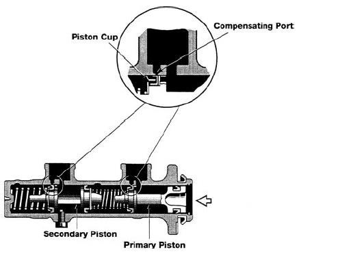
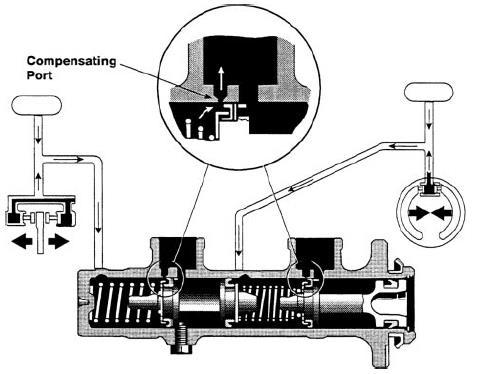
36 CONSTRUCTION MASTER CYLINDER The master cylinder has a single bore separated into two separate chambers by the Primary and Secondary pistons. On the front of the master cylinder primary piston is a rubber piston cup which seals the primary circuit of the cylinder. Another piston cup is also fitted at the rear of the primary piston to prevent the brake fluid from leaking out of the rear of the cylinder. At the front of the secondary piston is a piston cup which seals the secondary circuit. At the rear of the secondary piston the other piston cup seals the secondary cylinder from the primary cylinder. The primary piston is linked to the brake pedal via a pushrod.
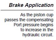
37 NORMAL OPERATION When the brakes are not applied, the piston cups of the primary and secondary pistons are positioned between the Inlet port and the compensating port. This provides a passage between the cylinder and reservoir tank. The secondary piston is pushed to the right by the force of secondary return spring, but prevented from going any further by a stopper bolt. When the brake is depressed, the primary piston moves to the left. The piston cup seals the compensating port blocking the passage between the primary pressure chamber and the reservoir tank. As the piston is pushed farther, it builds hydraulic pressure inside the cylinder and is applied or transmitted to the wheel cylinders in that circuit. The same hydraulic pressure is also applied to the secondary piston. Hydraulic pressure in the primary chamber moves the secondary piston to the left also. After the compensating port of the secondary chamber is closed, fluid pressure builds and is transmitted to the secondary circuit.
38
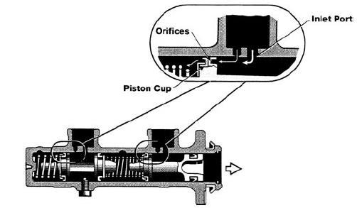
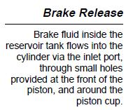
39 BRAKE RELEASE When the brake pedal is released, the pistons are returned to their original position by hydraulic pressure and the force of the return springs. However because the brake fluid does not return to the master cylinder immediately, the hydraulic pressure inside the cylinder drops momentarily. As a result, the brake fluid inside the reservoir tank flows into the cylinder via the inlet port, through small holes provided at the front of the piston, and around the piston cup. This design prevents vacuum from developing and allowing air to enter at the wheel cylinders. After the piston is returned to its original position, fluid enters from the wheel cylinder circuit to the reservoir through the compensating port.
40
41 BRAKE CIRCUIT CONFIGURATIONS Legal regulations define a dual-circuit transmission device as mandatory. Of the five options defined two versions (II and X) have become standard. To ensure compliance with legal regulations governing secondary braking forces, front-heavy vehicles are equipped with a diagonal (X pattern) brake system; in this layout, each brake circuit controls one front wheel along with one rear wheel on the opposite side. A system with separate circuits for the front and rear axles (II pattern) is particularly well-suited for use on rear-heavy vehicles and on medium-heavy and heavy-duty commercial vehicles. The remaining configurations (HT, LL, HH) are less satisfactory in terms of safety. As a result, the first two versions (II and X) are employed for virtually all applications

42 MASTER CYLINDER & BRAKE BOOSTER
43 POWER BRAKES These are the brakes wherein the power of the engine and or the battery power is used to enhance the braking effort. Four types Vacuum brakes Air brakes Brakes with hydraulic booster Electro hydraulic booster. The hydraulic booster systems usually employ pressure from the power steering system to increase pressure on the master cylinder whereas electrohydraulic booster systems use an electric motor to pressure the hydraulic system beyond the brake pedal i.e., in the entire brake system. The advantage of this system is that even if the engine fails, the power brakes would function so long there is battery power available. In case of vacuum brakes the vacuum from the inlet manifold is utilized, due to which the vacuum power brakes would not function if the engine is not working.
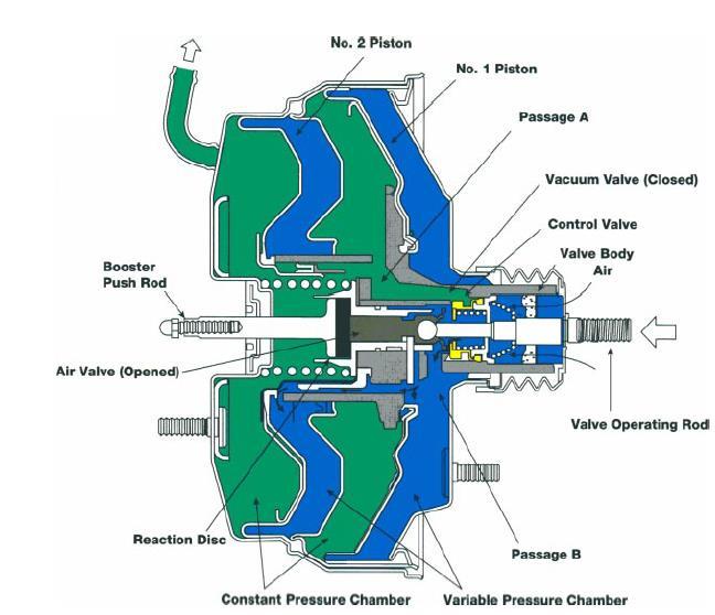
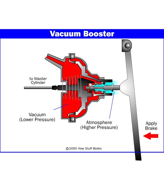
44 VACUUM BOOSTER BRAKES The brake booster is designed to create a greater braking force from a minimum pedal effort, using a difference in atmospheric pressure and the engine s manifold vacuum. It increases the pedal force to 2 to 4 times depending on the size of the diaphragm. The brake booster is located between the brake pedal and the master cylinder. When pressure is applied to the brake pedal, pressure is exerted on the booster air valve. With pressure created by the booster the master cylinder is applied. Should the booster malfunction, the normal mechanical braking force of the master cylinder is maintained. CONSTRUCTION The brake booster consists of the body, booster piston, piston return spring, reaction mechanism and control valve mechanism. The body is divided into a constant pressure chamber and a variable pressure chamber. The chambers are separated from each other by a diaphragm. The control valve mechanism regulates the pressure inside the variable pressure chamber.


45


46 BOOSTER AIR VALVE OPERATION In the off position, the air valve (connected to the valve operating rod) is pulled to the right by the air valve return spring. The control valve is pushed to the left by the control valve spring. This causes the air valve to contact the contract valve. Therefore, the atmospheric air that passes through the air cleaner element is prevented from entering the variable pressure chamber. The piston s vacuum valve is separated from the control valve in this position, providing an opening between passage A and passage B. Since there is always vacuum in the constant pressure chamber, the opening allows vacuum into the variable pressure chamber. As a result the piston is pushed to the right by the piston return spring.


47 In the ON position, when the brake pedal is depressed, the valve operating rod pushes the Air valve to the left. The control valve which is pushed against the air valve by the control valve spring moves to the left until it touches the vacuum valve. This blocks off the opening between passage A and passage B (constant pressure chamber (A) and variable pressure chamber (B)).


48 As the air valve moves further to the left, it moves away from the control valve. This allows atmospheric pressure to enter the variable pressure chamber through passage B. The pressure difference between the constant pressure chamber and the variable pressure chamber causes the piston to move to the left. This in turn causes the reaction disc to move the booster push rod to the left and exert braking force


49 When the brake pedal is released the valve operating rod and the air valve are moved to the right by the air valve return spring and reaction force of the master cylinder. This movement causes the air valve to contact the control valve, blocking atmospheric pressure from the variable pressure chamber. At the same time, the air valve also retracts the control valve spring. The control valve moves away from the vacuum valve, connecting passage A with passage B. This allows atmospheric pressure from the variable pressure chamber to flow into the constant pressure chamber. The pressure difference is eliminated between the two chambers and the piston is pushed back to the right by the diaphragm/piston return spring. The booster returns to the released position.


50 The tandem type brake booster is a compact and extremely powerful unit having two constant pressure chambers and two variable pressure chambers. A piston separates each variable and constant pressure chamber. With two pistons incorporated into this design, a large surface area provides additional boost while taking less space. TANDEM BRAKE BOOSTER

51 TANDEM BRAKE BOOSTER
52
53
54 BRAKES WITH HYDRAULIC BOOSTER This type of power assisted brakes is the bendix hydromax brakes which are a typical example of especially suitable for diesel engine vehicles. The system is claimed to be more compact, lighter, permitting lower pedal height and generally faster acting than other available vacuum brake systems. The two essential parts of the system are the hydromax booster and mini master cylinder.
55 In the hydromax booster, fluid under pressure from the power steering system enters the inlet port, flows through the pressure valve and power piston, the flow switch and exits from the return port. When the driver presses the brake pedal, pedal rod is actuated which activates a pressure valve restricting flow through the power piston. The resulting differential pressure on the power piston applies force on the master cylinder.

56 HYDROMAX BOOSTER AND MINI MASTER CYLINDER

57 AIR BRAKES The operation of air brakes is similar to the hydraulic brakes except that in their case compressed air is used to apply pressure instead of hydraulic pressure. Air brake commonly used on heavy vehicles like trucks, buses etc. 1. air compressor, 2. pressure regulator, 3. air dryer, 4. regeneration reservoir, 5. four way protection valve, 6. compressed air reservoirs, 7. park brake hand control valve, 8. park brake safety release valve, 9. brake foot valve, 10. front air brake chambers, 11. brake relay valve + load sensing valve, 12. rear spring brake chambers,
58 AIR BRAKE SUPPLY SYSTEM: The air compressor is driven by the engine either by crankshaft pulley via a belt or directly from the engine timing gears. It is lubricated and cooled by the engine lubrication and cooling systems. Compressed air is first routed through a cooling coil and into an air dryer which removes moisture and oil impurities and also may include a pressure regulator, safety valve and a smaller purge reservoir. As an alternative to the air dryer, the supply system can be equipped with an anti freeze device and oil separator. The compressed air is then stored in a reservoir (also called a wet tank) from which it is then distributed via a four way protection valve into the front and rear brake circuit air reservoir, a parking brake reservoir and an auxiliary air supply distribution point. The system also includes various check, pressure limiting, drain and safety valves.


59 AIR BRAKE OPERATION An air brake system uses compressed air to apply the brakes. Air under pressure can be conveniently stored and carried through lines or tubes. Considerable force is available for braking since operating air pressure may be as high as 100 psi. All brakes on a vehicle and on a trailer (when one is used) are operated together by a brake valve.
60 Air Compressor The air compressor pumps air into the air storage tanks (reservoirs). The air compressor is driven by the engine through gears or a V-belt. The compressor may be air-cooled or may be cooled by the engine lubrication system. It may have its own oil supply or be lubricated by engine oil. If the compressor has its own oil supply, the oil should be checked during your prestart operations. Governor The governor controls the air compressor output. When air tank pressures rise to the cutout level at about 125 pounds per square inch (psi), the governor stops the compressor from pumping air. When the tank pressure falls to the cut-in pressure at about 100 psi, the governor allows the compressor to start pumping again. Air Storage Tanks Air storage tanks (reservoirs) are used to hold compressed air. The number and size of air tanks varies among vehicles. The tanks hold enough air to allow the brakes to be used several times, even if the compressor stops working.

61 Alcohol Evaporator Some air brake systems have an alcohol evaporator to put alcohol into the air system. This helps reduce the risk of ice in air brake valves and other parts during cold weather. Ice inside a brake system can make the brakes stop working. Safety Valve A safety relief valve is installed in the first tank into which the air compressor pumps air. The safety valve protects the tank and the rest of the system from too much pressure. The valve is usually set to open at 150 psi. AIR BRAKES
62 Brake pedal The brakes are applied by depressing the brake pedal (also called the foot valve) that gives the operator control of the air brake system. When the brake pedal is engaged, air from the air tanks flows through the brake pedal valve through the brake lines to the brake chambers close to the wheel brakes that contain flexible diaphragms. The force of the air admitted into these chambers causes the diaphragms to operate the brake shoes through a mechanical linkage. Pushing the pedal down harder applies more air pressure. Letting up on the brake pedal reduces the air pressure and releases the brakes. Releasing the brakes allows some compressed air out of the system; therefore, the air pressure in the tanks is reduced and it must be recharged by the air compressor. Pressing and releasing the pedal unnecessarily may release air out faster than the compressor can replace it, and should the pressure become too low, the brakes cannot work properly and brake failure will occur.

63 AIR DISC BRAKES

64 An exhaust brake is a means of slowing a diesel engine by closing off the exhaust path from the engine, causing the exhaust gases to be compressed in the exhaust manifold, and in the cylinder. Since the exhaust is being compressed, and there is no fuel being applied, the engine works backwards, slowing down the vehicle. The amount of negative torque generated is usually directly proportional to the back pressure of the engine. An exhaust brakes not only increases the braking efficiency of vehicle but also increases the life of service brakes. They also prevent the brakes from overheating on downhill grades, as this causes brake fade and possibly even failure. Using exhaust brakes properly can help service brakes last up to three times longer. ENGINE EXHAUST BRAKE
65 ENGINE EXHAUST BRAKES This type of brake is used on TATA vehicles as an auxiliary brake and is meant for use while traveling on a lengthy downhill gradient and in heavy traffic when it becomes necessary to slow down continuously over a large distance. The main components of this brake are the pressure regulator (common with the service brakes operated by compressed air), a foot control valve for actuating the exhaust brake and an air cylinder wherein the compressed air operates the linkage to actuate the control lever of the governor. The brake comes into operation when the foot control valve is pressed and remains engaged as long as this valve is kept pressed. The moment the foot is taken off the valve, the brake gets released. When the foot control valve is pressed, the compressed air from the air tank enters the air cylinder, where it operates a linkage to close the butterfly valve at the exhaust manifold, which also cuts off the fuel supply through linkage. In this way this type of brakes effect fuel economy also. This brake is very effective below vehicle speed of 40 kmph. However it must be remembered it cannot stop the vehicle like a service brake.
66 PARKING BRAKES OR SECONDARY BRAKES OR HAND BRAKES The parking brake system is a secondary braking system used to hold a parked car in position. They are applied independently of the service brakes. Since there is no inertia to overcome, less braking power is required to hold the vehicle stationary and less force is required to apply. The application of only two of the four brake assemblies are required to hold the vehicle. There are three types of parking brake systems. Two types use the service brake and the other is an exclusive parking brake design. The service type parking brake uses part of the ordinary service brake mechanism and operates the shoe or piston mechanically. The parking brake lever is located near the driver s seat. Pulling the parking brake lever by hand or pressing the pedal with the foot, operates the brake via a cable connected to the parking brake lever of the brake assembly. The parking brake lever is provided with a ratchet locking mechanism to maintain the lever at the position to which it was set until released.
67

68 Parking brake linkage The parking brake cable transmits the lever movement through a typical series of components to the brake drum subassembly. The intermediate lever multiplies the operating force to the equalizer. The equalizer divides the lever operating force to brake assemblies at both wheels. The two major parts may vary in design but the function remains the same.
69 Pull-press-button Hand-Lever This construction, the most popular type at present, uses a hand-lever. One end of the hand lever is connected directly to the brake cable while the other end forms the handgrip, with a release press button. This lever is pivoted on a ratchet bracket. When the driver pulls up the lever arm, the spring-loaded pawl slides over the ratchet teeth causing maximum cable tension. To release the parking brake, the driver to relax the tension on the pawl, and then presses in the press-button with the thumb, so that the pawl teeth are rotated clear of the ratchet teeth. This causes the hand lever to returns fully down to the released position.


70 Drum parking brake On all models using drum brakes on the rear, the cable pulls the parking brake lever. The lever is attached to the secondary shoe at the top and transfers the lever action to the primary shoe through the shoe strut. When released the brake shoe springs return the shoes to their retracted position.
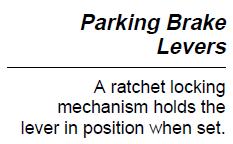
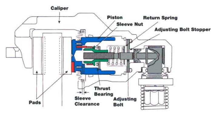
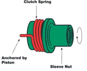
71 Caliper parking brake DISC PARKING BRAKES This type uses the brake caliper assembly to mechanically apply pressure to the disc. The parking brake is built into the caliper housing and is provided with an automatic adjusting mechanism to compensate for piston movement as the brake pads wear. Parking brake operation When the parking brake is applied, the cable attached to the parking brake lever rotates the crank lever counterclockwise. The crank pin then pushes the strut to the left. The strut moves the adjusting bolt, sleeve nut, and piston toward the left. As the strut moves to the left, it also compresses the adjusting bolt return spring. The assembly moves until it presses the pads against disc rotor. When the parking brake is released, the compressed return spring pushes the adjusting bolt and piston back to their previous positions. As a result the brake is released. During this operation, the clutch spring prevents the rotation of the sleeve nut so that the force of the parking brake lever is transferred to the piston via the adjusting bolt.

72


73 EXCLUSIVE PARKING BRAKE The second type is an exclusive drum brake assembly that applies pressure to an inside drum, which is an integral part of the disc rotor. A drum brake is cast into the disc rotor. The shoes and other components are similar to conventional drum brake system but smaller and with no wheel cylinder
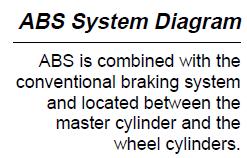
74 ANTI-LOCK BRAKING SYSTEMS (ABS) ABS are integrated with the conventional braking system. They use a computer controlled actuator unit between the brake master cylinder and the wheel cylinders to control brake system hydraulic pressure. ABS address two conditions related to brake application; wheel lockup and vehicle directional control. The brakes slow the rotation of the wheels, but it is actually the friction between the tire and road surface that stops the vehicle. Without ABS when brakes are applied with enough force to lock the wheels, the vehicle slides uncontrollably because there is no traction between the tires and the road surface. While the wheels are skidding, steering control is lost as well. An antilock brake system provides a high level of safety to the driver by preventing the wheels from locking. ABS is capable of modulating the brake pressure at a given wheel up to fifteen times per second. It controls each front brake separately and the rear brakes as a pair whenever one of the wheels starts to lock. ABS helps stop a car in the shortest possible distance without wheel lockup while maintaining directional control on most types of road surface or conditions.

75
76
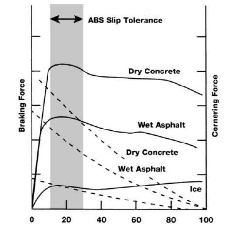
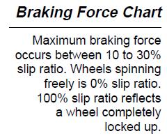
77 Basic operation 4 wheel ABS systems use a speed sensor at each front wheel and either a single speed sensor for both rear wheels or individual speed sensors at each rear wheel. The speed sensors are monitored by a dedicated ECU. The system controls the front brakes individually and rear brakes as a pair. In a panic braking situation, the wheel speed sensors detect any sudden changes in wheel speed. The ABS ECU calculates the rotational speed of the wheels and the change in their speed, then calculates the vehicle speed. The ECU then judges the slip ratio of each wheel and instructs the actuator to provide the optimum braking pressure to each wheel. For example, the pressure to the brakes will be less on slippery pavement to reduce brake lockup. As a result braking distance may increase but directional control will be maintained. The hydraulic actuator operates on signals from the ABS ECU to hold, reduce or increase the brake fluid pressure as necessary, to maintain the optimum slip ratio of 10 to 30% and avoid wheel lock up.

78
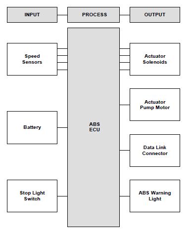
79 DLC DATA LINK CONNECTOR ABS COMPONENTS LAYOUT
80 BLEEDING OF HYDRAULIC BRAKES In hydraulic brakes care must be taken that not even small quantities of air enter into the braking system. The air being compressible, it gets compressed when the brake pedal is pressed. The result is that fluid pressure is not transmitted to the brakes which, as a consequence are not actuated. The procedure for driving air out of the braking system is called bleeding. A special bleeding valve is provided for this purpose on the shoe expander or disc caliper. For bleeding, the master cylinder is topped up completely with the brake fluid and pipe is connected to the bleeding valve nipple. The other end of this pipe is dipped in the brake fluid contained in some jar. One person sits on the driver s seat and presses the brake pedal, after which the bleeder valve is opened by the second person with a spanner, when some air bubbles will come out of the pipe and escape through the brake fluid into the atmosphere. The bleeder valve is now closed and the brake pedal released and pressed once more after which the bleeder valve is opened again when some more bubbles will come out. This procedure is repeated till on pressing the brake pedal no more air bubbles are noted when with the pedal in the pressed position the bleeder valve is closed. The reservoir is then topped up with the fresh fluid. This procedure is repeated for all wheels.
81 SUSPENSION SYSTEM All the parts which perform the function of isolating the automobile from the road shocks are collectively called a suspension system Objective of a Suspension system To prevent the road shocks from being transmitted to the vehicle components. To safeguard the occupants from road shocks. To preserve the stability of the vehicle in pitching or rolling, while in motion. Basic considerations Brake dip: on braking the nose of the vehicle has a tendency to be lowered or to dip. This depends upon the position of centre of gravity relative to the ground, the wheelbase and other suspension characteristics. This phenomenon is called dip. Ride and handling: ride is the qualitative ability of a vehicle to provide a smooth, comfortable drive on a bumpy road. Handling is the ability of a vehicle to safely accelerate, brake and corner. Unsprung weight: unsprung weight is the weight of vehicle components between the suspension and the road surface. This includes rear axle assembly, steering knuckle, front axle in case of rear rigid axle suspension, wheels, tyres and brakes. Sprung weight: the sprung weight i.e. the weight supported by the vehicle suspension system, includes the frame, body, engine and the entire transmission system
82 Types of Suspension springs The various suspension springs may be classified as follows: 1. Steel springs a) Leaf spring b) Tapered leaf spring c) Coil spring d) Torsion bar 2. Rubber springs a) Compression spring b) Compression shear spring c) Steel reinforced spring d) Progressive spring e) Face-shear spring f) Torsional shear spring 3. Plastic spring 4. Air spring 5. Hydraulic spring


83 LEAF SPRINGS Semi elliptic leaf springs are almost universally used for suspension in light and heavy commercial vehicles. The leaves consist of a number of leaves called blades. The blades vary in length. The composite spring is based upon the theory of a beam of uniform strength. The lengthiest blade has eyes on its ends. This blade is called the master leaf. All the blades are bound together by means of steel straps. The spring is supported on the axle, front or rear by means of a U bolt. One end of the spring is mounted on the frame with a simple pin, while on the other end, connection is made with a shackle. The spring may be cambered initially or flat. Highly cambered springs provide a soft suspension. Flat springs reduce the tendency of the vehicle to dip i.e. pitching, when braking or accelerating suddenly.

84 TYPES OF LEAF SPRINGS


85 COIL SPRINGS The coil springs are used mainly with independent suspension though they have also been used in the conventional rigid axle suspension as they can be well accommodated in restricted spaces. The energy stored per unit volume is almost double in the case of coil springs than the leaf springs. Coil spring do not have noise problems, nor do they have static friction causing harshness of ride as in case of leaf springs. The spring takes the shear as well as bending stresses. The coil springs cannot take torque reaction and side thrust for which alternate arrangements have to be provided.

86 TORSION BARS Torsion bar is simply a rod acting in torsion and taking shear stresses only. They are made of heat treated alloy spring steel. The amount of energy stored per unit weight of material is nearly the same as for coil springs. Torsion bar is often used with the independent suspension. Torsion bar spring is lighter as compared to leaf springs and also it occupies less space. Two main disadvantages of torsion bar: It does not take the braking or driving thrust so that additional linkages have to be provided for that purpose. The absence of friction force and hence of damping which is necessity to control the vibrations produced due to road shocks.
87 RUBBER SPRINGS The advantages of using rubber as a means of suspension are: 1. It can store energy per unit weight than the steel. For this reason rubber springing system can be made more compact. 2. The rubber has excellent vibration damping properties. 3. The absence of squeaking which is always present in steel springs. 4. The number of bearings is reduced considerably for the rubber suspension system. This means longer life. 5. Rubber is more reliable. A rubber suspension cannot fail like the metal springs. The different types of rubber springs are
 It provides a rising rate characteristic. (iii.) It can resist occasional overload of large magnitude. (iv.) It has a large measure of inherent damping than most types of rubber springs.")
88 a.) Compression spring This type of spring is still being used because of the following advantages: (i.) It is reliable, of simple construction and requires no bonding. (ii.) It provides a rising rate characteristic. (iii.) It can resist occasional overload of large magnitude. (iv.) It has a large measure of inherent damping than most types of rubber springs. Its use is limited because of the fact that some mechanical guide must be provided with this type of spring and the provision of mechanical guide is generally undesirable.
89 b.) Compression shear spring In this type, the load is carried partly by shear and partly by compression components in the rubber and hence although large strains may be allowed in the rubber body, shear stress at the bonded faces is kept small and fatigue properties are excellent. c.) Steel reinforced spring Steel reinforced spring (Eligos spring) consists of a steel helical spring bonded in a rubber body. The steel springing, though carrying only about 20% of the load, exercises a stabilizing influence on the rubber component thereby allowing a greater stroke/diameter ratio to be used without other forms of guiding. d) Progressive spring It has initially an exceedingly small rate which rises rapidly as the central cavity closes. e) Face shear spring It consists of a thick disc of rubber having metal plates bonded to its flat surfaces and axially precompressed. It operates by relative rotation of the plates about its axis thus loading the rubber partly in shear.
90 f) Torsional shear spring It consists of an inner metal shaft, tubular or solid and an outer trough like shell between which rubber body is bonded, the latter being put under pressure by closing the trough with a riveted or spot welded base plate. The spring operates by the rotation of the shaft about its own axis relative to the shell.
91 SHOCK ABSORBERS A springing device must be a compromise between flexibility and stiffness. If it is more rigid, it will not absorb road shocks efficiently and if it is more flexible it will continue to vibrate even after the bump has passed. So we must have sufficient damping of the spring to prevent excessive flexing. The friction between the leaves of a leaf spring provides this damping but because of the uncertainty of the lubrication conditions, the amount of friction also varies and hence the damping characteristics do not remain constant. For this reason, the friction between the springs is reduced to minimum and additional damping is provided by means of devices called dampers or shock absorbers. In the case of coil springs, the whole of damping is provided by the shock absorbers. The shock absorbers thus control the excessive spring vibrations. The shock absorber absorbs the energy of shock converted into vertical movement of the axle by providing damping and dissipating the same into heat. It merely serves to control the amplitude and frequency of spring vibrations. Damper is a better term technically to describe the shock absorber.

92 PRINCIPLE OF OPERATION The principle of operation of a hydraulic shock absorber is that when a piston forces the fluid in a cylinder to pass through some hole, a high resistance to the movement of piston is developed which provides the damping effect. TELESCOPIC SHOCK ABORBER Telescopic shock absorber derives its name form the tubular shape of early telescopes. These are of two types mono tube type and twin tube type.

93 TWIN TUBE SHOCK ABSORBER

94 TWIN TUBE SHOCK ABSORBER BUMP/COMPRESSION On bump, or compression, the piston and rod move downwards in the cylinder, resulting in a small pressure drop in the chamber labeled A, above the piston. At the same time, the volume of the chamber labeled B, below the piston, is reduced, causing a high fluid pressure. This unseats the piston intake valve, and fluid flows up through the outer passages in the piston, and into chamber A. But the piston rod is also now entering A, and displacing a quantity of fluid equal to its volume, so, all of the oil in B cannot flow into A. The displaced fluid is forced down through a base valve, and out into the reservoir, labeled C.
95 REBOUND In the rebound, or extension phase, the piston and rod move upwards and the volume of chamber A is reduced. Chamber A becomes a high-pressure area, and fluid flows through the extension valve in the piston, into chamber B. However the withdrawal of the piston from B greatly increases its volume, and fluid flow from a is insufficient to fill the space. Pressure in B falls below that of the reservoir, causing the base intake valve to be unseated. Fluid flows from the reservoir into chamber B, keeping the inner tube full. The valves provide control over the amount of force required to pass fluid through them at any given piston velocity. They can be made to open in stages, according to fluid pressure. This allows light resistance to motion, when the piston moves slowly, and heavy resistance when piston velocity is high.
96 INDEPENDENT SUSPENSION When a vehicle with rigid axle suspension encounters road irregularities, the axle tilts and the wheels no longer remain vertical. This causes the whole of the vehicle to tilt on one side. Apart from causing rough ride, it causes wheel wobble, the road adhesion is also decreased. To avoid this the wheels are sprung independent of each other, so that tilting of one does not effect the other. Independent suspension has the following advantages: Elastic strain energy per unit spring weight stored in a coil or torsion bar spring is greater than in case of semi elliptic leaf spring, which means lighter springs can be used in case of independent suspension. In case of independent suspension, unsprung weight is reduced, which ultimately reduces the tyre scrub and hence increases tyre life. Compared to the rigid axle type softer springs can be used without increasing rolling effect, soft springs improve ride comfort. Improved steering precision since wheel movements are not linked In case of independent suspension it is possible to locate the springs apart enough to obtain understeer conditions which is preferred to oversteer condition. With independent suspension steering geometry is not altered with spring deflection as in case of rigid axle suspension where effect is especially noticeable during braking or acceleration. As there is no solid axle beam which required clearance for its vertical movements, the engine and the chassis frame can be place relatively lower which means engine position can be moved forward resulting in more space for passengers.
97 Disadvantages of Independent suspension: Initial cost is high. Greater maintenance required because of larger number of bearings. Misalignment of steering geometry with the wear of components, thus requiring more attention. In the event of body roll, the wheel camber due to which cornering power is reduced. More rigid sub frame or chassis frame required. Forces due to unbalanced wheels are more pronounced and transmitted easily to the steering wheel

98 FRONT WHEEL (DEAD AXLE) INDEPENDENT SUSPENSION Four types of independent suspension are in use for front axle: 1. Wishbone type of parallel link type 2. Mac Pherson strut type 3. Vertical guide suspension 4. Trailing link type 5. Swinging half axle type Wishbone type suspension It consists of upper and lower wishbone arms pivoted to the frame member. These arms resemble letter A of the roman alphabet due to which they are referred to as A arms. The spring is placed between the lower wishbone and the underside of the cross member. The vehicle weight is transmitted from the body and the cross member to the coil spring through which it goes to the lower wishbone member. A shock absorber is placed inside the coil spring and is attached to the cross member and to lower wish bone.


99 The wishbone arms are like the chicken wishbone or letter V in shape, because of which the system is so called. Because of this V shape, the wishbones not only position the wheels and transmit the vehicle load to the springs, but these also resist acceleration, braking and cornering forces. The upper arms are shorter in length than the lower ones. This helps keep the wheel track constant, thereby avoiding the tyre scrub thus minimizing tyre wear. Small changes in camber angle does occur with this arrangement Mac Pherson strut suspension In this layout only lower wishbones are used. A strut containing shock absorber and the spring carries also the stub axle on which the wheel is mounted. The wishbone is hinged to the cross member and positions the wheel as well as resists accelerating, braking and side forces. This system is simpler than double wishbone type and is also lighter keeping the unsprung weight lower.


100 Camber does not change when the wheel moves up and down. This type of suspension gives the maximum room in the engine compartment and is therefore, commonly used on front wheel drive cars.

101 Vertical guide suspension The kingpin is attached directly to the cross member of the frame. It can slide up and down as shown, corresponding to the up and down motion of the wheel, thus compressing or elongating the springs. In this the track, wheel base and wheel attitude remain unchanged, but the system is having disadvantage of decreased stability. Trailing link suspension In this type of suspension a coil spring is attached to the trailing link which itself is attached to the shaft carrying the wheel hub. When the wheel moves up and down, it winds and unwinds the spring. A torsion bar has also been used in certain designs in place of coil spring. This system does maintain the camber and the wheel track constant. The distance between the front and rear wheels does change. Swinging half axle suspension In this the wheels are mounted rigidly on the half axles, which are pivoted on their ends to the chassis member at the middle of the car. The main disadvantage of this system is that up and down movement of the wheel causes camber angle to vary.
102 REAR WHEEL (LIVE AXLE INDEPENDENT SUSPENSION) Three types of independent suspension are in use for rear axle: 1. Trailing link type 2. Semi trailing link or arm suspension 3. Multi link suspension Trailing link type and semi trailing link In this type the trailing links are pivoted at right angles to the longitudinal axis of the car and carry the rear wheels at their ends. Universal joints on this suspension keep the wheel track and the camber constant with the up and down movement of the wheels. Coil spring with shock absorbers mounted concentrically within them are used in this suspension. The trailing links hold the wheels firmly and also sustain accelerating and braking forces. The trailing link or arm runs from a point forward on the floorpan back to the wheel assembly while a leading link or arm is mounted to the floorpan behind the wheel. Although the camber remains constant with respect to the vehicle body, yet when the vehicle rolls into a corner, the trailing arm rolls for the same degree as the vehicle body thus changing the camber angle with respect to the road surface.

103 As both wheels now lean towards the outside of the corner, it leads to understeer. When these arms are mounted at an angle to the longitudinal axis of the vehicle, these are known as semi trailing link or arm suspension. The trailing arms are generally inclined from 20 to 40 degrees to the longitudinal axis. Thus the forces may be resolved into the longitudinal and the transverse directions. Longitudinal forces cause understeer while the transverse component produces oversteer due to body roll. As a result the two components cancel each other giving almost neutral steer. The semi - trailing link result in camber angle changes with the up and down movements of the wheel. The increased unsprung weight due to the trailing arms give rise to poor ride quality.


104 Multi link suspension A multi link suspension is difficult to describe since theoretically any suspension having three control arms or more is a multi link suspension. For ex: Honda Accord s multi link is only a double wishbone suspension with an additional control arm.


105 AIR/PNEUMATIC SUSPENSION Air suspension is a type of vehicle suspension powered by an electric or engine driven air pump or compressor. This pump pressurizes the air, using compressed air as a spring. Air suspension is often used in place of conventional steel springs, and in heavy vehicle applications such as buses and trucks. If the engine is left off for an extended period, the vehicle will gradually settle to the ground. The purpose of air suspension is to provide a smooth, constant ride quality and in most cases it is self-leveling. Air pressurizes the bag and in turn raised the chassis from the axle. Although traditionally called air bags, the correct term is air bellows.

106 DIFFERENT AIR SPRINGS 1. Stud: A permanent part of the bead plate assembly used to attach the air spring to the suspension. 2. Combo Stud: Combination mounting stud and air fitting. 3. Blind Nut: A permanent part of the bead plate assembly providing an alternate mounting system to the stud. 4. Air Fitting Hole: A tapped hole providing air entrance for the part. 5. Bead Plate: Permanently crimped onto the bellows at the factory allowing complete part leak testing prior to shipment. 6.Bellows: The heart of an Airide spring. Includes at least four plies, or layers, of material an inner liner, two plies of cord-reinforced fabric, and an outer layer. 7. Bumper (Optional): A solid molded rubber, fail-safe device used on many suspension applications. Prevents excessive damage to vehicle and suspension in the case of sudden air pressure loss. 8. Piston: The lower section of certain styles of airspring made from aluminum, steel or fiber reinforced plastic. Provides the lower mounting arrangement for the airspring, in the form of tapped holes or studs. 9. Piston Bolt: Attaches the piston to the bellows assembly. The piston bolt is extended, in some cases, to serve as a means of attaching the spring to the suspension. 10. Girdle Hoop: A ring between the convolutions of the convoluted type.

107 Air suspension advantage: A variable space for wheel deflection is put to optimum use by virtue of the automatic control devices. The vehicle height is also constant, changes in head lamp alignment due to varying loads are avoided. The spring rate varies much less between the laden and unladen conditions, as compared with that of conventional steel springs. The improved standard of ride comfort and noise reduction attained with air springs reduces both driver and passenger fatigue.
108 Air suspension layout
109 Working The four air springs, which may be either the bellows type or the piston type are mounted on the same position where the coil springs are mounted. An air compressor takes the atmospheric air through a filter and compresses it to a pressure of about 240 MPa, at which pressure the air on the accumulator tank is maintained, which is also provided with a safety relief valve. This high pressure air goes through the lift control valve and the leveling valves to the air spring. The lift control valve is operated manually by means of a handle on the control panel, through a cable running from the valve to the handle.

110 CONTINENTAL ELECTRONIC AIR SUSPENSION The Electronic Air Suspension system (EAS) by Continental Automotive Systems, Germany works in conjunction with Electronic Stability Control (ESC), to automatically adapt damping and spring characteristics along with the vehicle s body level, to driving conditions and load changes thereby: i. Reducing rolling and pitching movements ii. Reducing other body movements iii. iv. Reducing the wheel load fluctuations Achieving a definite gain in driving dynamics and comfort. Sensors and electronics from both EAS and ESC result in a perfectly tuned reaction of suspension, engine control and brake control even under critical driving conditions.


111 A system where the front and rear suspension systems were connected together HYDROLASTIC in order to SUSPENSION better level the car when driving. The front and rear suspension units have Hydrolastic displacers, one per side. These are interconnected by a small bore pipe. Each displacer incorporates a rubber spring Damping of the system is achieved by rubber valves. When the front wheel encounter bumps,the piston moves upwards pressurizing the fluid to enter into the rear unit. Hydroelastic was eventually refined into Hydragas suspension.

112 Known as hydro-pneumatic suspension. The difference is in the displacer unit itself. HYDROGAS SUSPENSION In the older systems, fluid was used in the displacer units with a rubber spring cushion built-in. With Hydragas, the rubber spring is removed completely. The fluid still exists but above the fluid there is now a separating membrane or diaphragm, and above that is a cylinder or sphere which is charged with nitrogen gas. The nitrogen section is what has become the spring and damping unit whilst the fluid is still free to run from the front to the rear units and back.
113 WHEELS Various requirements of an automobile wheel are: It must be strong enough to perform the above functions. It should be balanced both statically as well as dynamically. It should be lightest possible so that the unsprung weight is least. It should be possible to remove or mount the wheel easily. Its material should not deteriorate with weathering and age. In case, the material is susceptible to corrosion, it must be given suitable protective treatment. Types of wheels The pressed steel disc wheel The wire wheel Light alloy wheel


114 The pressed steel disc wheel Simple construction, robust wheel. Most preferred by over 90 percent manufacturers. Require negligible maintenance and are easy to produce. Consists of two parts, a steel rim to receive the tyre and a pressed steel disc. A typical pressed steel disc has the disc welded to the rim.


115 Wire wheel Unlike the disc wheel the wire wheel has a separate hub, which is attached to the rim through a number of wire spoke. Each spoke is individually hooked at one end of the hub while its other end is passed through a hole in the wheel rim, where a tapered nut, called nipple is screwed down pulling the spoke tight. If a spoke is too loose or too tight, the rim would distort. The spokes carry the weight transmit the driving and braking torques and withstand the side forces while cornering in tension. Spokes are long thin wires and as such these cannot take any compressive or bending stresses. The spokes are mounted in a complicated criss cross fashion in all the three planes.

116 Light alloy wheel Latest trend is use of automobile wheels made from aluminium or magnesium alloys. Cast wheels are used for cars while forged wheels are preferred for wheels of heavier vehicles. Main advantage of light alloy wheel weighs about 50 per cent of a steel wheel and about 70 per cent of an aluminium alloy wheel for similar strength. Light alloys are better conductors of heat which helps the wheels dissipate any heat generated by the tyres or brakes and thereby run cooler. Light alloy cast wheels improve stability on cornering.

117 Magnesium alloys have high impact and fatigue strength so that they can stand vibration and shock loading better. Prone to corrosion so must protective coating. Aluminium alloys do not have high resistance to vibration and shock as in case of magnesium alloys but these are relatively easier to cast or forge and also less prone to corrosion. Aluminium alloys are used for wheels of cars and commercial vehicles whereas sports and racing cars usually have magnesium alloy wheels.
118 A tyre is a cushion provided with an automobile wheel. It consists of mainly the outer cover i.e. the tyre proper and the tube inside. The tyre tube assembly is mounted over the wheel rim. It is the air inside the tube that carries the entire load and provides the cushion. The tyre performs the following functions: To support the vehicle load. To provide cushion against shocks. To transmit driving and braking forces to the road. To provide cornering power for smooth steering. TYRE Cross section of a truck tyre
119 TYPES OF TYRES The pneumatic tyres may be classified according to the following considerations: Basic construction Use Ability to run flat Basic construction According to this criteria, the tyres may be conventional tyre with tube and the tubeless tyre. Conventional tubed tyre: It consists of two main parts the carcass and the tread. The carcass is the basic structure taking mainly the various loads and consists of a number of plies wound in a particular fashion from the cords of rayon on any other suitable material.

120 Each cord in each ply is covered with resilient rubber compounds and all the plies are insulted against each other. The term ply rating which is often used in tyre industry does not indicate exact number of plies on the tyre, it is only a relative index of tyre strength and load carrying capacity. In order to prevent the tyre from being thrown off the rim, the plies are attached to two rings of high tension steel wire. These rings are made to fit snugly against the wheel rim threreby anchoring the tyre to the rim. These rings are called beads.

121 The tread is the part of the tyre which contacts the road surface when the wheel rolls. It serves to transmit the forces between the rest of the tyre and the ground. It is generally made of synthetic rubber and on the design of the tyre tread depend on various tyre properties i.e. the grip, the noise and the wear. The tread is moulded into a series of grooves and ribs. The ribs provide the traction edges required for gripping the road surfaces while the grooves provide passage for quick escape of any foreign matter such as water. Traction edges and sipes are provided on the ribs. Sipes are the small grooves moulded into the ribs of the tyre tread. These increase the traction ability of the tyre by increasing number of traction edges. As the tyre flexes on the road surface, the sipes open to provide extra gripping action. Sipes also act like a sponge by mopping up water when opening on the ground and releasing the same when closing while moving up.

122 There are three types of tread pattern i.e Symmetrical Asymmetrical Unidirectional Symmetrical tyre where both halves of the tread face are exactly similar. Asymmetrical tyre where the tread pattern changes across the tyre face. Unidirectional are designed to rotate in only one direction, unidirectional means different sets of tyres for different sides of the vehicle, rotational direction arrow on the side wall.
123 Tubeless tyres This type of tyre does not need a separate tube; instead the air pressure is filled in the tyre itself for which purpose a non return valve is fitted to the rim. The inner construction of the tyre is almost same as that of tubed tyre, except that it is lined on inside with a special retaining linermdae up of halogenated butyl rubber for better air impermeability together with high heat and weather resistance. Stability of tyre is maintained by the bead in a tubed tyre, in a tubeless tyre it also serves to maintain the air pressure within. The bead heel sits more tightly within the flange of the rim, this enhances the high speed performance while achieving high cornering power.

124 Tubeless tyres have the following advantages over conventional tubed tyres: Lesser unsprung weight Better cooling: heat in the compressed air has to pass through the tube material i.e. rubber which is not a good conductor of heat. Since there is no tube in the tubeless tyres, heat can be passed onto the atmosphere directly. Lesser rolling resistance: no internal tube to generate friction, thereby eliminating heat generated by the internal shuffling of the tube. Comfortable ride: shocks and vibrations absorbed at tyre level. Slower leakage of air: inner liner not stretched like the tube, retains air better. Simpler assembly: only tyre has to be fit over the rim. Improved safety.
125 Use 1. All season tyres These are the tyres that one commonly finds on almost all production cars. They are designed by compromising on performance, grip noise and life. They are made of harder rubber for longer life, which decreases grip and cornering power. Tread design also compromised between quiet running and wet weather safety. 2. Summer tyres Performance and grip preferred over the life span and therefore made from softer rubber compound. Tread design is such that provides out right grip rather than ability to remove water efficiently. 3. Wet weather tyres Have more sipes for dispersing water from the contact patch. Small slit like grooves called sipes in the tread blocks that allow the blocks to flex Increased flexibility increases the traction. Wet weather tyres made from softer rubber their life is 50% less than all season types


126 4. Snow/ice tyres larger tread block patterns, which makes them noisier. Extreme climates, snow tyres have small metal stud inserts which bite into the snow and ice. Much shorter life and extremely noisy if run over dry roads. 5. All terrain tyres Commonly used on suv s and pick ups. Larger in size and have stiffer sidewalls and bigger tread block patterns. Increases their grip when on loose sand and dirt when running off road, but are more noisy on normal roads.

127 Ability to run flat Flat running tyres are designed to resist the effects of deflation and to enable the vehicle to be driven continuously after the puncture at reasonable reduced speeds for limited distances of about 80 km/h. Three types of technologies available for run flat tyres. These are 1. Self sealing tyres 2. Self supporting tyres 3. Auxiliary supported tyres 1. Self sealing tyres This type of tyre has standard construction, difference additional lining under the tread area which is coated with a puncture sealant which can seal permanently punctures upto about 4mm in diameter When the tyre is first punctured sealant provides a seal around the puncturing object and later when object is removed the hole in the tread is filled in automatically.

128 Example for self sealing tyres: Pirelli seal inside tyres. What is Seal Inside? Seal Inside (S.I.) is a new tyre construction technology that allows you to drive on without losing air pressure even after the tyre has been punctured by an external object, covering almost 85% of the possible accidental causes of pressure loss*. How does it work? Inside the tyre, in the area corresponding to the tread pattern, a sealing layer material tightly blocks every possible air leakage in case of a puncture that passes through the carcass with or without an external object still present. The Seal Inside deals immediately with the hole and its fast and effective action, in most cases, does not make the driver realize that the tyre has been punctured.

129 2. Self supporting tyres Self-supporting tires feature a stiffer internal construction, which is capable of temporarily carrying the weight of the vehicle, even after the tire has lost all air pressure. To provide "self-supporting" capability, these tires typically attach rubber inserts next to or between layers of heat-resistant cord in their sidewalls to help prevent breaking the reinforcing cords in the event of loss of air pressure. They also feature specialized beads that allow the tire to firmly grip current Original Equipment and aftermarket wheels even in the event of air loss. Because self-supporting tires are so good at masking the traditional loss-of-air symptoms that accompany a flat tire, they require a tire pressure monitoring system to alert the driver that they have lost air pressure. Without such a system, the driver may not notice under inflation and may inadvertently cause additional tire damage by failing to inflate or repair the tire at the first opportunity. Typically, self-supporting tires maintain vehicle mobility for 80 km at speeds up to 85 kmph.

, and minimizes the responsibility of the tire (which does periodically wear")

130 3. Auxiliary supported tyres / auxiliary supported run flat systems In these systems, the flat tire's tread rests on a support ring attached to the wheel when the tire loses pressure. The advantage to this type of system is that it will place most of the mechanical task of providing run-flat capability on the wheel (which typically doesn't wear out or need to be replaced), and minimizes the responsibility of the tire (which does periodically wear out and requires replacement). Additionally, auxiliary support systems promise better ride quality because their sidewall's stiffness can be equivalent to today's standard tires. The disadvantage to auxiliary supported systems is that their unique wheels will not accept standard tires and that their lower volume will make this type of system more expensive.


131 TWEEL AIRLESS TYRE BY MICHELIN The tyre is totally airless and therefore puncture proof, which means no spare wheel is needed. It consists of four parts; the hub, a polyurethane spoke section, a shear band surrounding the spoke and the tread band, which is a rubber layer, wrapping around the circumference and touching the road. The sir pressure of the conventional tyre is replaced here by the tension of the shear band on the spokes and the strength of the spokes themselves.

132 CARCASS TYPES The carcass or skeleton of the tyre is of 3 types: 1. Cross ply or bias ply 2. Radial ply 3. Belted bias type. 1. Cross ply type: In this type, the ply cords are woven at an angle (30-40 ) to the tyre axis. There are two layers which run in the opposite directions. The cords are not woven like warp and weft of ordinary cloth because that would lead to rubbing of the two layers and thus produce heat which would damage the tyre material.

133 2. Radial ply type In this type the ply cords run in the radial direction i.e. in the direction of the tyre axis. Over this basic structure run a number of breaker strips in the circumferential direction. The material for the breaker strips must be flexible but inextensible so that no change of circumference take place with change in the amount of inflation. Without the breaker strips, radial plies would give very soft ride, but there will not be any lateral stability. The inextensible breaker strip behaves like a girder in its own plane and provides the directional stability.

134 3. Belted bias type This is a combination of cross ply and radial ply type. The basic construction is the bias ply over which run a number of breaker belts. The belts improve the characteristics of the bias ply tyre to a large extent. The stresses in the carcass are restricted and the tread area is stabilized due to belts. This results in reduction of tread scrubbing thus causing increase of traction and safety. The belts increase the resistance of the tyre to cuts and punctures.

135 Ride Comfort. STATIC AND ROLLING PROPERTIES OF TYRES The bending of the walls of cross-ply tyres requires a shear action to change the criss-cross ply angle, which makes the walls very stiff, and hence the bounce on rough roads is not properly cushioned. Radial-ply tyre construction provides a supple wall due to the natural direction of radial-ply cords. These tyres bend readily and hence can absorb a great deal of extra bounce. The radial-ply tyre is more comfortable at higher speeds because of its shockabsorbing deflection characteristic, which is 25% greater than that of the cross-ply type. However at lower speeds the cross-ply tyre provides more smooth riding and the steering is also lighter, so that it is more suitable for parking.
136 Acceleration and Braking. Conventional cross-ply tyres tread is affected by every movement of the walls because tread is not braced and held down on to the road. As a result of this the tread blocks are able to shift and dance about on the road surface providing a small contact area, which reduces road grip. In radial-ply tyres, the braced layers of cords act independently of the wall plies. The bracing belt follows the contour of the road during movement of the wheel providing a continuous large flat contact-patch area with the road surface. The whole of the tread pattern is fully stabilized, so that road-wheel acceleration and braking are improved.

137 Cornering. Cross-ply tyres do not bend sufficiently to absorb any sideways strain during cornering. Cross-plies therefore pull and lift up one side of the tread from the ground, reducing road grip and traction. Radial-ply tyre during concerning bends readily and absorbs extra strain. The tread stays firm and flat down, with its whole working area of tread pattern biting into the surface of the road. Tyre Life. With a cross-ply tyre, when the wheel rolls, the distortion of the walls tends to pull the tread away from the road surface, thereby scraping the tread blocks as road contact begins and ends. A radial-ply tyre produces a flat full-width track-laying action along the wheeland-road interface. The full width tread pattern contact during cornering and the extended flat zone reduce wear during driving and stopping. This extends tyre life considerably by as much as 80%

138 Tyre section The ratio (tyre section height/tyre section width) is called the aspect ratio and is expressed in percentage. Initially aspect ratio of 100% was used but later lower aspect ratio became increasingly popular. Advantages of lower aspect ration are: Better load carrying capacity Less wear Higher cornering power Better performance at high speeds Main disadvantage is the uncomfortable because of less vertical flexibility. With better designed suspension systems it has now been possible to use aspect ratios as low as 50%.
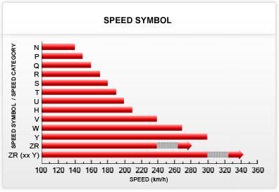
139 TYRE DESIGNATIONS
Chapter 33 Fundamentals of Hydraulic and Air-Over-Hydraulic Braking Systems
 Chapter 33 Fundamentals of Hydraulic and Air-Over-Hydraulic Braking Systems Introduction Vehicle s braking system must meet the following requirements: To adequately and safely reduce a vehicle s speed,
Brake Systems. Introduction
 Brake Systems Figure 1. A Typical Brake System Introduction The brake system (Figure 1) is designed to slow and halt the motion of a vehicle. To do that, various components within a hydraulic brake system
DESCRIPTION & OPERATION
 DESCRIPTION & OPERATION BRAKE BOOSTER Delco-Moraine Single Diaphragm A combined vacuum-hydraulic unit which uses a combination of intake manifold vacuum and atmospheric pressure to provide power assist.
Braking System Layout
 The Braking System The energy used to accelerate or move a vehicle from rest to a certain speed is called Kinetic i (moving) energy. To slow the vehicle down, this kinetic energy must be converted or changed,
Brake System Operation
 Brake System Brake System Operation Donald Jones Brookhaven College Master cylinder Brake lines Hydraulic valves Disc brakes Drum brakes Power assist unit Parking brake Antilock system Brake System Functions
MASTER CYLINDER. Section 2. Lesson Objectives
 MASTER CYLINDER Lesson Objectives 1. Explain the difference between conventional and diagonal split piping system and their application. 2. Describe the function of the compensating port of the master
C. Brake pads Replaceable friction surfaces that are forced against the rotor by the caliper piston.
 BRAKES UNIT 1: INTRODUCTION TO BRAKE SYSTEMS LESSON 1: FUNDAMENTAL PRINCIPLES OF BRAKE SYSTEMS I. Terms and definitions A. Brake fading Loss of brakes, usually due to heat. B. Brake lining Material mounted
Unit HV04K Knowledge of Heavy Vehicle Chassis Units and Components
 Assessment Requirements Unit HV04K Knowledge of Heavy Vehicle Chassis Units and Components Content: Chassis layouts i. types of chassis ii. axle configurations iii. rear steered axles iv. self-steered
BRAKE SYSTEM FUNDAMENTALS KARAN BHARDIYA ASSISTANT MANAGER -R&D ENDURANCE TECHNOLOGIES PVT.LTD. DISC BRAKES
 BRAKE SYSTEM FUNDAMENTALS KARAN BHARDIYA ASSISTANT MANAGER -R&D ENDURANCE TECHNOLOGIES PVT.LTD. DISC BRAKES AUTOMOTIVE BRAKING SYSTEMS How brakes manufacturing industry is different then rest of the automotive
1. INTRODUCTION. Anti-lock Braking System
 1. INTRODUCTION Car manufacturers world wide are vying with each other to invent more reliable gadgets there by coming closer to the dream of the Advanced safety vehicle or Ultimate safety vehicle, on
DRIVE-CONTROL COMPONENTS
 3-1 DRIVE-CONTROL COMPONENTS CONTENTS FRONT SUSPENSION................... 2 Lower Arms............................... 5 Strut Assemblies........................... 6 REAR SUSPENSION.....................
ANTI-LOCK BRAKES. Section 9. Fundamental ABS Systems. ABS System Diagram
 ANTI-LOCK BRAKES Fundamental ABS Systems Toyota Antilock Brake Systems (ABS) are integrated with the conventional braking system. They use a computer controlled actuator unit, between the brake master
Modern Auto Tech Study Guide Chapters 71 & 73 Pages Brake Systems 49 Points. Automotive Service
 Modern Auto Tech Study Guide Chapters 71 & 73 Pages 1369 1444 Brake Systems 49 Points 1. Automotive systems use to stop, slow or to hold the wheels from turning. Brake, Friction Brake, Fraction Brake,
AIR BRAKES THIS SECTION IS FOR DRIVERS WHO DRIVE VEHICLES WITH AIR BRAKES
 Section 5 AIR BRAKES THIS SECTION IS FOR DRIVERS WHO DRIVE VEHICLES WITH AIR BRAKES AIR BRAKES/Section 5 SECTION 5: AIR BRAKES THIS SECTION COVERS Air Brake System Parts Dual Air Brake Systems Inspecting
MECA0063 : Braking systems
 MECA0063 : Braking systems Pierre Duysinx Research Center in Sustainable Automotive Technologies of University of Liege Academic Year 2018-2019 1 Bibliography T. Gillespie. «Fundamentals of vehicle Dynamics»,
FUNDAMENTAL PRINCIPLES
 Section 1 FUNDAMENTAL PRINCIPLES Lesson Objectives 1. Describe the cycle of heat as it applies to automotive brakes. 2. Explain the effect of heat transfer as it relates to brake fade. 3. Describe how
DISC BRAKES. Section 4. Components and Operation of Disc Brakes. Disc Brake Assembly
 DISC BRAKES Components and Operation of Disc Brakes A disc brake assembly consists of a: cast iron disc (disc rotor) that rotates with the wheel. caliper assembly attached to the steering knuckle. friction
Auto Fundamentals: brakes
 1 of 38 29/09/2006 13:27 Auto Fundamentals: brakes After studying this chapter, you will be able to: Identify the basic parts of the brake hydraulic system Describe the principles used for brake hydraulic
Driver Driven. InputSpeed. Gears
 Gears Gears are toothed wheels designed to transmit rotary motion and power from one part of a mechanism to another. They are fitted to shafts with special devices called keys (or splines) that ensure
SECTION 4A BRAKE SYSTEM TABLE OF CONTENTS
 SECTION 4A BRAKE SYSTEM TABLE OF CONTENTS Description and Operation... 4A-2 Braking System Testing... 4A-2 Hydraulic Brake System... 4A-2 Brake Pedal... 4A-2 Master Cylinder... 4A-2 Brake Booster... 4A-3
BRAKE SYSTEM Return To Main Table of Contents
 BRAKE SYSTEM Return To Main Table of Contents GENERAL... 2 BRAKE PEDAL... 10 MASTER CYLINDER... 13 BRAKE BOOSTER... 16 BRAKE LINE... 18 PROPORTIONING VALVE... 19 FRONT DISC BRAKE... 20 REAR DRUM BRAKE...
Module 11: Antilock Brakes Systems
 ÂÂ ABS Brake System Antilock Brake System Operation Principles of ABS Braking ABS Master Cylinder Hydraulic Control Unit Wheel Speed Sensors ABS Electronic Control Unit Terms and Definitions Purposes for
White Paper: The Physics of Braking Systems
 White Paper: The Physics of Braking Systems The Conservation of Energy The braking system exists to convert the energy of a vehicle in motion into thermal energy, more commonly referred to as heat. From
Section 5 AIR BRAKES. This Section Covers. Air Brake System Parts Dual Air Brake Systems Inspecting Air Brakes Using Air Brakes
 Section 5 AIR BRAKES This Section Covers Air Brake System Parts Dual Air Brake Systems Inspecting Air Brakes Using Air Brakes This section tells you about air brakes. If you want to drive a truck or bus
INSTALLATION INSTRUCTIONS
 INSTALLATION INSTRUCTIONS REAR DISC BRAKE CONVERSION KIT A158 1994-97 Dodge Ram 1500 (2WD & 4WD) and REAR DISC BRAKE CONVERSION KIT A158-1 1998-01 Dodge Ram 1500 (2WD & 4WD) Thank you for choosing STAINLESS
Parking brake Mechanical brake acting on rear wheels
 11 Brake System 11.1 General SPECIFICATIONS EJTC0010 Master cylinder Type Tandem type I.D. mm(in.) 20.64 mm (0.813 in.) Fluid level warning sensor Provided Brake booster Type Vacuum Boosting ratio 4.0
TRADE OF HEAVY VEHICLE MECHANIC
 TRADE OF HEAVY VEHICLE MECHANIC PHASE 2 Module 5 Braking Systems UNIT: 1 Table of Contents 1. Learning Outcome... 1 1.1 Key Learning Points... 1 2.0 Health and Safety... 3 2.1 Principles of Braking...
The parts of these systems are discussed in greater detail below.
 Section 5 Air Brakes This Section Covers Air Brake System Parts Dual Air Brake Systems Inspecting Air Brakes Using Air Brakes This section tells you about air brakes. If you want to drive a truck or bus
BRAKES. Section III REAR AXLE DATA AND SPECIFICATIONS HAND BRAKE CHRYSLER SERVICE MANUAL BRAKES 17
 BRAKES 17 There is no basic design change in the rear axle and sure grip differential except the larger diameter pinion shaft is now used on all models for 1959. The Service Procedures will remain the
1999 Toyota RAV BRAKES Disc & Drum - Trucks & Vans
 DESCRIPTION & OPERATION 1999-2000 BRAKES Disc & Drum - Trucks & Vans WARNING: For warnings and procedures regarding vehicles equipped with Anti-Lock Brake Systems (ABS), see appropriate ANTI-LOCK article.
A proportioning valve is used to regulate brake pressure between front and rear brakes. Rear brakes on all models are self-adjusting.
 Page 1 of 21 ARTICLE BEGINNING DESCRIPTION & OPERATION WARNING: For warnings and procedures regarding vehicles equipped with Anti- Lock Brake Systems (ABS), see ANTI-LOCK BRAKE SYSTEM article in the BRAKES
DRIVETRAIN 7.0 Introduction 7.1 Drivetrain configurations 7.2 Drivetrain elements 7.3 Clutch Operation
 DRIVETRAIN 7.0 Introduction Drivetrain is the assembly of all the components that are involved in the transmission of the power from the engine of the vehicle to its wheels. 7.1 Drivetrain configurations
INSTALLATION INSTRUCTIONS
 INSTALLATION INSTRUCTIONS REAR DISC BRAKE CONVERSION KITS A112, A112-1 & A112-93 1979-93 FORD MUSTANG with 7.5" & 8.8" AXLES Thank you for choosing STAINLESS STEEL BRAKES CORPORATION for your braking needs.
BRAKE BOOSTER. Section 5. Brake Booster. Construction. Single Diaphragm Booster
 BRAKE BOOSTER Brake Booster The brake booster is designed to create a greater braking force from a minimum pedal effort, using a difference in atmospheric pressure and the engine s manifold vacuum. It
Shock Absorbers What is Ride Control Vehicle Dynamics Suspension System Shock Absorbers Struts Terminology
 Home Tech Support Shock Absorbers Shock Absorbers What is Ride Control Vehicle Dynamics Suspension System Shock Absorbers Struts Terminology A BRIEF HISTORY These first shock absorbers were simply two
III B.Tech I Semester Supplementary Examinations, May/June
 Set No. 1 III B.Tech I Semester Supplementary Examinations, May/June - 2015 1 a) Derive the expression for Gyroscopic Couple? b) A disc with radius of gyration of 60mm and a mass of 4kg is mounted centrally
Brake System H TX, H2.0TXS [B475]; H TX [B466] Safety Precautions Maintenance and Repair
![Brake System H TX, H2.0TXS [B475]; H TX [B466] Safety Precautions Maintenance and Repair](/thumbs/86/93834005.jpg "Brake System H TX, H2.0TXS [B475]; H TX [B466] Safety Precautions Maintenance and Repair") HMM180001 Brake System H1.5-1.8TX, H2.0TXS [B475]; H2.5-3.5TX [B466] Safety Precautions Maintenance and Repair When lifting parts or assemblies, make sure all slings, chains, or cables are correctly fastened,
HMM180001 Brake System H1.5-1.8TX, H2.0TXS [B475]; H2.5-3.5TX [B466] Safety Precautions Maintenance and Repair When lifting parts or assemblies, make sure all slings, chains, or cables are correctly fastened,
INSTALLATION INSTRUCTIONS
 INSTALLATION INSTRUCTIONS DISC BRAKE CONVERSION KITS A121-1, A121-2, A121-3, A121-4 1967-69 Ford & Mercury Thank you for choosing STAINLESS STEEL BRAKES CORPORATION for your braking needs. Pleases take
A 1 SERVICE SPECIFICATIONS
 A1 A2 Clutch CLUTCH Specifications Pedal height (from asphalt sheet) Release point (from pedal stroke end position) Push rod play at pedal top Pedal freeplay Disc rivet head depth Disc runout Diaphragm
This file is available for free download at
 This file is available for free download at http://www.iluvmyrx7.com This file is fully text-searchable select Edit and Find and type in what you re looking for. This file is intended more for online viewing
STEERING SYSTEM Introduction
 STEERING SYSTEM Introduction The steering makes it possible to change direction. The steering must be reliable and safe; there must not be too much play in the steering. It must be possible to steer accurately.
3 Axles and brakes. 3.1 Function and construction of the axles Construction Function
 3 Axles and brakes 3.1 Function and construction of the axles 3.1.1 Function Each wheel has an independent suspension system in the axle body (1), so that individual wheel suspension is provided. The swinging
Module 6: Air Foundation Brakes
 Air Brakes Terms and Definitions Basic Components That Make Up Air Foundation Brakes Types of Air Foundation Brakes Parts of a Cam Foundation Brake Parts of a Wedge Foundation Brake Parts of a Disc Foundation
INSTALLATION INSTRUCTIONS
 INSTALLATION INSTRUCTIONS BIG ROTOR / CALIPER RELOCATION REAR KIT SUM-BK1423 1999-2009 GM 1/2 Ton Trucks & SUVs Thank you for choosing SUMMIT RACING for your braking needs. Pleases take the time to read
Mopar 8 3/4 & 9 3/4 (Dana) Installation Instructions Rear Disc Conversion
 Installation Instructions Rear Disc Conversion") Mopar 8 3/4 & 9 3/4 (Dana) Installation Instructions Rear Disc Conversion This kit is for either Mopar 8 ¾ or Mopar 9 ¾ (Dana). This kit is designed to work with axles with either GM 5 x 4.75 Bolt Pattern
Mopar 8 3/4 & 9 3/4 (Dana) Installation Instructions Rear Disc Conversion This kit is for either Mopar 8 ¾ or Mopar 9 ¾ (Dana). This kit is designed to work with axles with either GM 5 x 4.75 Bolt Pattern
To study about various types of braking system.
 To study about various types of braking system INTRODUCTION The system is purely mechanical means & is independent of the hydraulic system which controls the brake normally. A brake commonly referred to
COASTAL BEND COLLEGE AUTOMOTIVE TECHNOLOGY SYLLABUS (rev. Fall 2012)
") COASTAL BEND COLLEGE AUTOMOTIVE TECHNOLOGY SYLLABUS (rev. Fall 2012) AUMT 1310: Automotive Brake Systems SEMESTER HOURS: 3 TEXTBOOK Automotive Technology A systems Approach COURSE DESCRIPTION; Operation
COASTAL BEND COLLEGE AUTOMOTIVE TECHNOLOGY SYLLABUS (rev. Fall 2012) AUMT 1310: Automotive Brake Systems SEMESTER HOURS: 3 TEXTBOOK Automotive Technology A systems Approach COURSE DESCRIPTION; Operation
Disc Brake System Principles
 C H A P T E R 1 4 Disc Brake System Principles Chapter Objectives At the conclusion of this chapter you should be able to: KEY TERMS brake pads brake rotors caliper pistons composite rotor dust boot fade
Chapter. Steering System Technology
 Chapter 78 Steering System Technology Objectives After studying this chapter, you will be able to: Explain the operating principles of steering systems. Identify the major parts of a steering system. Compare
INSTALLATION INSTRUCTIONS
 INSTALLATION INSTRUCTIONS REAR DISC BRAKE CONVERSION KIT A126-1 1973-87 CHEVROLET 1/2 TON 2WD Thank you for choosing STAINLESS STEEL BRAKES CORPORATION for your braking needs. Pleases take the time to
ENGINE MECHANICAL <134>
 11A-1 GROUP 11A ENGINE MECHANICAL CONTENTS GENERAL INFORMATION........ 11A-2.................. 11A-3 11A-2 The newly developed 1.1L 134910 engine features 3-cylinder, 12-valve, and double overhead
BURQUIP INTERNATIONAL (PTY) LTD
 LTD") Chapter 6 Transmission The transmission system comprises all of the components that transfer the force and movement from the Braked Coupler to the inertia brakes in the axles. Fit the axles to the trailers
Chapter 6 Transmission The transmission system comprises all of the components that transfer the force and movement from the Braked Coupler to the inertia brakes in the axles. Fit the axles to the trailers
INSTALLATION INSTRUCTIONS
 INSTALLATION INSTRUCTIONS PERFORMANCE AT THE WHEELS KITS W156-6 & W156-7 1965-74 MOPAR B & E BODY Thank you for choosing STAINLESS STEEL BRAKES CORPORATION for your braking needs. Pleases take the time
CLASSIFICATION OF ROLLING-ELEMENT BEARINGS
 CLASSIFICATION OF ROLLING-ELEMENT BEARINGS Ball bearings can operate at higher speed in comparison to roller bearings because they have lower friction. In particular, the balls have less viscous resistance
BRAKE SYSTEM DESIGN AND THEORY
 RAKE SYSTEM DESIGN AND THEORY Aircraft brake systems perform multiple functions. They must be able to hold the aircraft back at full static engine run-up, provide adequate control during ground taxi operations,
US ARMY LIGHT WHEEL VEHICLE MECHANIC MOS 63B SKILL LEVEL 3 COURSE WHEELED VEHICLE BRAKING SYSTEMS SUBCOURSE NO. OD1008
 US ARMY LIGHT WHEEL VEHICLE MECHANIC MOS 63B SKILL LEVEL 3 COURSE WHEELED VEHICLE BRAKING SYSTEMS SUBCOURSE NO. OD1008 US Army Ordnance Center and School Five Credit Hours GENERAL The Wheeled Vehicle Braking
INSTALLATION INSTRUCTIONS
 INSTALLATION INSTRUCTIONS R1 REAR DRUM TO DISC BRAKE CONVERSION KIT A130-3 JEEP CJ SERIES W/AMC-20 REAR AXLES AND 5 x 5-1/2" BOLT CIRCLE Thank you for choosing STAINLESS STEEL BRAKES CORPORATION for your
Hydro-Max Hydraulic Brake Booster and Master Cylinder. Technical Manual
 Hydro-Max Hydraulic Brake Booster and Master Cylinder Technical Manual * 5+0 Important Service Notes The information in this publication was current at the time of printing. The information presented in
II YEAR AUTOMOBILE ENGINEERING AT AUTOMOTIVE CHASSIS QUESTION BANK UNIT I - LAYOUT, FRAME, FRONT AXLE AND STEERING SYSTEM
 II YEAR AUTOMOBILE ENGINEERING AT 6402 - AUTOMOTIVE CHASSIS QUESTION BANK UNIT I - LAYOUT, FRAME, FRONT AXLE AND STEERING SYSTEM 1. Write about the requirements of frame and selection of cross section
Topic 1. Basics of Oil Hydraulic Systems
 Topic 1. Basics of Oil Hydraulic Systems Fluid power Fluid power is the technology that deals with the generation, control and transmission of forces and movement of mechanical element or system with the
DRIVE AXLE Volvo 960 DESCRIPTION & OPERATION AXLE IDENTIFICATION DRIVE AXLES Volvo Differentials & Axle Shafts
 DRIVE AXLE 1994 Volvo 960 1994 DRIVE AXLES Volvo Differentials & Axle Shafts 960 DESCRIPTION & OPERATION All 960 station wagon models use type 1041 rear axle assembly. All 960 4-door models use type 1045
Braking system. Basic requirement of a braking system
 Braking system The most vital factor in the running and control of the modern vehicle is the braking system. In order to bring the moving vehicle to rest or slow down, the energy of the vehicle processed
INSTALLATION INSTRUCTIONS
 INSTALLATION INSTRUCTIONS REAR DISC BRAKE CONVERSION KITS SUM-BK1329-X, SUM-BK1329-99904, SUM-BK1330-X, SUM-BK1330-99904 CHRYSLER 8 3 /4", 9 3 /4" and 2-PIECE REAR AXLES Thank you for choosing SUMMIT RACING
INSTALLATION INSTRUCTIONS
 INSTALLATION INSTRUCTIONS DISC BRAKE CONVERSION KIT A120-20, A120-21 1964 1 /2-66 Ford & Mercury Thank you for choosing STAINLESS STEEL BRAKES CORPORATION for your braking needs. Pleases take the time
INSTALLATION INSTRUCTIONS
 INSTALLATION INSTRUCTIONS PERFORMANCE AT THE WHEELS KIT W120-22, W120-23 1964 1/2-69 MUSTANG Thank you for choosing STAINLESS STEEL BRAKES CORPORATION for your braking needs. Pleases take the time to read
INSTALLATION INSTRUCTIONS
 INSTALLATION INSTRUCTIONS REAR DISC BRAKE CONVERSION KIT A125-3 1965-72 GM A-BODY 10 & 12 BOLT AXLES Thank you for choosing STAINLESS STEEL BRAKES CORPORATION for your braking needs. Pleases take the time
SRI VIDYA COLLEGE OF ENGINEERING & TECHNOLOGY DEPARTMENT OF MECHANICAL ENGINEERING. ME AUTOMOBILE ENGINEERING Question Bank
 SRI VIDYA COLLEGE OF ENGINEERING & TECHNOLOGY DEPARTMENT OF MECHANICAL ENGINEERING ME6602 - AUTOMOBILE ENGINEERING Question Bank UNIT-4 - STEERING, BREAKS AND SUSPENSION PART-A 1. Define wheel track and
INSTALLATION INSTRUCTIONS
 INSTALLATION INSTRUCTIONS REAR CONVERSION KITS SUM-BK1326-X, SUM-BK1326-99904, SUM-BK1327-X, SUM-BK1327-99904, SUM-BK1328-X, SUM-BK1328-99904 FORD 8 and 9 AXLES WITH GM & FORD BOLT PATTERN Thank you for
Theory of Machines. CH-1: Fundamentals and type of Mechanisms
 CH-1: Fundamentals and type of Mechanisms 1. Define kinematic link and kinematic chain. 2. Enlist the types of constrained motion. Draw a label sketch of any one. 3. Define (1) Mechanism (2) Inversion
BRAKE SYSTEM Toyota Celica DESCRIPTION DRUM BRAKES ADJUSTMENTS BRAKE PEDAL HEIGHT ADJUSTMENTS BRAKE PEDAL FREE PLAY ADJUSTMENTS
 BRAKE SYSTEM 1988 Toyota Celica 1988-89 BRAKES Toyota Celica, Corolla, MR2, Tercel DESCRIPTION The hydraulic brake system uses a tandem master cylinder with a vacuum power assist servo. MR2 and some Celica
INSTALLATION INSTRUCTIONS
 INSTALLATION INSTRUCTIONS REAR DISC CONVERSION KIT SUM-BK1414-X 1997-2004 JEEP WRANGLER (TJ) WITH DANA 44 AXLES (non-abs) Thank you for choosing SUMMIT RACING for your braking needs. Pleases take the time
FUNDAMENTAL PRINCIPLES
 FUNDAMENTAL PRINCIPLES Fundamental Principles The most important safety feature of an automobile is its brake system. The ability of a braking system to provide safe, repeatable stopping is the key to
BRAKE SYSTEM Nissan 240SX DESCRIPTION BRAKE BLEEDING * PLEASE READ FIRST * BLEEDING PROCEDURES ADJUSTMENTS BRAKE PEDAL HEIGHT SPECS TABLE
 BRAKE SYSTEM 1990 Nissan 240SX 1990 BRAKE SYSTEMS Nissan Disc & Drum Axxess, Maxima, Pathfinder, Pickup, Pulsar NX, Sentra, Stanza, 240SX, 300ZX DESCRIPTION All brake systems are hydraulically operated
55-64 Full Size GM (Impala, Bel Air, etc.) This kit is for axles with a 3 3/8 spread center to center on the top two bolt holes (pictured left).
 This kit is for axles with a 3 3/8 spread center to center on the top two bolt holes (pictured left).") SUM-BK1624A Full Size GM Installation Instructions Rear Disc Conversion 55-64 Full Size GM (Impala, Bel Air, etc.) This kit is for axles with a 3 3/8 spread center to center on the top two bolt holes (pictured
SUM-BK1624A Full Size GM Installation Instructions Rear Disc Conversion 55-64 Full Size GM (Impala, Bel Air, etc.) This kit is for axles with a 3 3/8 spread center to center on the top two bolt holes (pictured
 DEPARTMENT OF MECHANICAL ENGINEERING Subject code: ME6601 Subject Name: DESIGN OF TRANSMISSION SYSTEMS UNIT-I DESIGN OF TRANSMISSION SYSTEMS FOR FLEXIBLE ELEMENTS 1. What is the effect of centre distance
INSTALLATION INSTRUCTIONS
 INSTALLATION INSTRUCTIONS Disc Brake Spindle Kit SUM-BKA2447 1964-72 A-BODY 1967-69 F-BODY 1968-74 X-BODY Thank you for choosing SUMMIT RACING for your braking needs. Please take the time to read and carefully
A /F/X Body Instruction Packet Rear Disc Conversion
 A /F/X Body Instruction Packet Rear Disc Conversion 64-72 A Body / 67-81 F Body / 62-74 X Body This kit is for axles with a 3 1/8 spread center to center on the top two bolt holes (pictured left). Rotor
INSTALLATION INSTRUCTIONS
 INSTALLATION INSTRUCTIONS BIG ROTOR / CALIPER RELOCATION FRONT KITS SUM-BK1422, BK1423, BK1424 1999-2006 GM 1/2 Ton Trucks & SUVs Thank you for choosing SUMMIT RACING for your braking needs. Pleases take
INSTALLATION INSTRUCTIONS
 INSTALLATION INSTRUCTIONS REAR DRUM TO DISC BRAKE CONVERSION KIT A130 JEEP CJ SERIES W/AMC-20 REAR AXLES AND 5 x 5-1/2" BOLT CIRCLE Thank you for choosing STAINLESS STEEL BRAKES CORPORATION for your braking
BRAKE SYSTEM Article Text 1996 Toyota RAV4 For Copyright 1998 Mitchell Repair Information Company, LLC Wednesday, September 13, :30PM
 Article Text ARTICLE BEGINNING 1996 BRAKES Toyota - Disc & Drum RAV4 * PLEASE READ THIS FIRST * WARNING: For warnings and procedures regarding vehicles equipped with Anti-Lock Brake Systems (ABS), see
INSTALLATION INSTRUCTIONS R1 REAR CONVERSION KIT
 INSTALLATION INSTRUCTIONS R1 REAR CONVERSION KIT INSTRUCTION FOR ASSEMBLY OF JEEP CJ SERIES W/AMC 20 REAR AXLES, 5 x 5-1/2" BOLT CIRCLE WITH A130-4 FULL FLOATING AXLE OR A130-5 (1 PIECE AXLE) Thank you
R10 Set No: 1 ''' ' '' '' '' Code No: R31033
 R10 Set No: 1 III B.Tech. I Semester Regular and Supplementary Examinations, December - 2013 DYNAMICS OF MACHINERY (Common to Mechanical Engineering and Automobile Engineering) Time: 3 Hours Max Marks:
INSTALLATION INSTRUCTIONS
 INSTALLATION INSTRUCTIONS REAR DISC CONVERSION KIT A136-1 1976-86 AMC 20 AXLES WITH WARN FULL FLOATING AXLE CONVERSION Thank you for choosing STAINLESS STEEL BRAKES CORPORATION for your braking needs.
INSTALLATION INSTRUCTIONS
 INSTALLATION INSTRUCTIONS REAR DRUM TO DISC BRAKE CONVERSION KIT A118 pre-1985 Ford F150 (except 1983-1984 w/super H/D axle) Thank you for choosing STAINLESS STEEL BRAKES CORPORATION for your braking needs.
INSTALLATION INSTRUCTIONS
 INSTALLATION INSTRUCTIONS REAR DISC BRAKE CONVERSION KIT A125-2 1955-70 FULL SIZE CHEVROLET Thank you for choosing STAINLESS STEEL BRAKES CORPORATION for your braking needs. Pleases take the time to read
Railway Technical Web Pages
 Railway Technical Web Pages Archive Page Vehicle Suspension Systems Introduction Almost all railway vehicles use bogies (trucks in US parlance) to carry and guide the body along the track. Bogie suspension
A. Adapter A metal component that fastens the caliper to the knuckle. Some brake systems do not use adapters.
 BRAKES UNIT 5: DISC BRAKE DIAGNOSIS AND REPAIR LESSON 3: SERVICE DISC BRAKE CALIPERS I. Terms and definitions A. Adapter A metal component that fastens the caliper to the knuckle. Some brake systems do
Automatic drain valves
 driving commercial vehicles If you notice more than a few drops of water when you drain the supply reservoir, the air dryer or compressor may need servicing. fast fact Even if the air brake system includes
Automatic Transmission Basics
 Section 1 Automatic Transmission Basics Lesson Objectives 1. Describe the function of the torque converter. 2. Identify the three major components of the torque converter that contribute to the multiplication
definition Retarders definition driving tip chapter 2 heavy vehicle braking Using retarders
 chapter 2 heavy vehicle braking Brake fade occurs when your brakes stop working properly because they're overheated. Your vehicle takes longer to stop, or may not stop at all if you haven't properly controlled
Ford 8, 9 Small Bearing Installation Instructions Rear Disc Conversion
 Ford 8, 9 Small Bearing Installation Instructions Rear Disc Conversion This kit is for Ford 9 rear axles with the small (2.835 ) style bearing and Ford 8 rear ends. This kit is designed to work with axles
SUSPENSION 2-1 SUSPENSION TABLE OF CONTENTS
 DN SUSPENSION 2-1 SUSPENSION TABLE OF CONTENTS page ALIGNMENT... 1 FRONT SUSPENSION - 4x2... 6 page FRONT SUSPENSION - 4x4... 14 REAR SUSPENSION... 23 ALIGNMENT TABLE OF CONTENTS page AND OPERATION WHEEL
Inspection and Basic Maintenance of Brake Systems
 Inspection and Basic Maintenance of Brake Systems 11-1 Types Air brakes Hydraulic brakes Secondary braking systems 11-2 Air Brake System Most large, modern fire apparatus are equipped with air-operated
Toyota Landcruiser Rear Brake Upgrade Package
 May 2007 Toyota Landcruiser Rear Brake Upgrade Package 9 Nevada Ct Hoppers Crossing Vic 3029 Ph 03 97486950 Fax 03 97485965 Email hopstop@hoppers.com.au Web www.hoppers.com.au 2 THE INFORMATION CONTAINED
Brake System Fundamentals Chapter 71 Name Date Period
 Brake System Fundamentals Chapter 71 Name Date Period Basic Brake System Matching 1. Metal tubing and rubber hose that transmit pressure to the wheel brake assemblies. 2. Mechanical system for applying
A double-wishbone type suspension is used in the front. A multi-link type suspension is used in the rear. Tread* mm (in.) 1560 (61.
 1560 (61.") CHASSIS SUSPENSION AND AXLE CH-69 SUSPENSION AND AXLE SUSPENSION 1. General A double-wishbone type suspension is used in the front. A multi-link type suspension is used in the rear. 08D0CH111Z Specifications
CHASSIS SUSPENSION AND AXLE CH-69 SUSPENSION AND AXLE SUSPENSION 1. General A double-wishbone type suspension is used in the front. A multi-link type suspension is used in the rear. 08D0CH111Z Specifications
Sudden Stop Ahead! Is Your Trailer Equipped with Nev-R-Adjust Brakes?
 www.dexteraxle.com Sudden Stop Ahead! Is Your Trailer Equipped with Nev-R-Adjust Brakes? Road hazards appear suddenly without warning. With a trailer behind you there s no time to second guess your ability
Marine Engineering Exam Resource Review of Couplings
 1. What are rigid couplings used for? Used to join drive shafts together. True alignment and rigidity are required. Example Drive shafts and production lines, bridge cranes, solid shaft that needs to be
TORQUE CONVERTER. Section 2. Lesson Objectives. 6 TOYOTA Technical Training
 Section 2 TORQUE CONVERTER Lesson Objectives 1. Describe the function of the torque converter. 2. Identify the three major components of the torque converter that contribute to the multiplication of torque.
INSTALLATION INSTRUCTIONS
 INSTALLATION INSTRUCTIONS FRONT DISC BRAKE CONVERSION KIT A129-2 1959-64 Full Size Chevrolet Car and FRONT DISC BRAKE CONVERSION KITS A129-3 & A129-4 1965-68 Full Size Chevrolet Car Thank you for choosing