Auto Fundamentals: brakes
|
|
|
- Molly Goodwin
- 6 years ago
- Views:
Transcription

1 1 of 38 29/09/ :27 Auto Fundamentals: brakes After studying this chapter, you will be able to: Identify the basic parts of the brake hydraulic system Describe the principles used for brake hydraulic system operation Identify the basic parts of the brake friction system Describe the principles used for brake friction system operation xplain the differences between drum and disc brakes Describe the principles and components of the vacuum power brake system Describe the principles and components of the hydraulic power brake system Describe the principles and components of anti-lock brake systems List the safety hazards and precautions involved in brake system repairs This chapter covers the components and operation of modern disc and drum brake systems. The brake system is subdivided into the hydraulic system (master cylinder, wheel cylinders, calipers, lines and hoses and valves), and friction system (brake shoes and drums, disc brake rotors and pads). This chapter also covers drum and disc parking brakes, vacuum and hydraulic power brake assists, and anti-lock brake and traction control systems. After studying this chapter, you will understand the operating principles and components of modern brake systems. Warning: Brake friction materials contain asbestos - a known carcinogen. Brake assemblies can produce small airborne particles of asbestos during cleaning, which are easily inhaled. Breathing these particles may cause emphysema or cancer. The following safety rules should be observed at all times: Never use compressed air to blow brake assemblies clean. Use a contained vacuum cleaning system or flush with cleaner or water. When some exposure might be unavoidable, wear an approved filter mask. Hydraulic Basics Early cars used complex linkages to operate the brakes. Modern vehicles use the principles of hydraulics to transfer power to the brakes. Hydraulics is the practical application of the principles of liquids in motion. Liquids can include water, oil, transmission fluid, and for our purposes in this chapter, brake fluid. Brake fluid, confined in a hydraulic system, is used to transmit both motion and pressure from the brake pedal to the wheels. A liquid under confinement can be used to : Transmit pressure Increase pressure Decrease pressure Transmit motion Air is Compressible, Liquids Are Not Air confined under pressure will compress, thereby reducing its volume, Figure When a liquid is confined and placed under pressure, it cannot be compressed. Figure 23-2A shows a cylinder filled with oil. A leak proof piston is placed on top of the oil. When a downward force is applied, as shown in Figure 23-2B, the force will not compress the oil. Pascal's Law A French scientist, Blaise Pascal, discovered that when pressure was exerted on a confined fluid, the pressure was transmitted undiminished throughout the fluid. Figure 23-3 illustrates Pascal's law. Notice that the original pressure (force) placed on the liquid is the same at all outlets. Figure 23-1.


2 2 of 38 29/09/ :27 Air is compressible. A - There is no pressure on the piston. B - Pressure has forced the piston down, compressing the air trapped in the container. Figure Liquids cannot be compressed. When pressure is applied to the piston in B, it does not compress the liquid. Figure When pressure is exerted on a confined liquid, it is transmitted undiminished. Force on the piston has created a pressure of 50 psi (pounds per square inch), upon the liquid in the pressure cylinder. Notice that all gauges read the same throughout the system. Pressure is transmitted undiminished to all parts of the system. If gauge A reads 50 psi, gauges B, C, D, and E will also read 50 psi. Liquids Can Transmit Motion and Force In Figure 23-4, you will see that any movement of piston A will cause piston B to move an equal amount. This is a transmission of motion though a liquid. If a 200 lb force is placed on piston A in Figure 23-5, piston B will support 200 lbs. Both pistons are the same size. In a hydraulic system, this force is usually expressed as hydraulic pressure. Liquids Can Increase Force When a force is applied to piston A in Figure 23-6, it can be increased if it is transmitted to a larger piston B. If piston A has a surface area of 1 sq. inch, the 200 lb force on piston A represents a pressure of 200 pounds per square inch (psi). According to Pascal's Law, this 200 psi force will be transmitted undiminished. If piston B has a surface area of 20 sq. inch, piston A will exert a 200 lb force on each square inch of piston B. This would produce a mechanical advantage (MA) of twenty, and the original 200 lb force would be increased to 4000 lbs. The force may be further increased by either making piston A smaller or piston B larger. Figure 23-4


3 3 of 38 29/09/ :27 p Liquids can transmit motion. A - Both pistons are at rest. B - Piston in the left cylinder has been forced down. When one piston travels down, it forces liquid into the other cylinder. Since the other cylinder is the same size, the distance that the piston will be raised is equal to the distance that the other piston was lowered. p Figure 23-5 p Using a liquid to transmit force. A 200 lb force on piston A is transmitted, via liquid, to piston B. p Figure 23-6 p Liquids can be used to increase force. A 200 lb force on piston A with an area of 1 sq. inch is increased to 4000 lbs on piston B with an area of 20 sq. inch. p Liquids Can Decrease Force If a force is applied to piston B, the original force of 200 lbs would have to be raised to 80,000 lbs to produce a pressure of 4000 lbs on piston A. By applying the force to the large piston, the force increase has been reversed and the original force, as applied to the small piston, will be diminished. This force's ability to produce pressure can be increased or decreased by applying it to a larger or smaller area. Notice in Figure 23-7 that pressures in the pump and lifting pistons are the same. However, the force applied to the pump piston has been increased many times on the head of the lift. Hydraulic Jack Figure 23-7 shows how a fluid can be used to produce a powerful lifting force using the principles of hydraulics. When the jack handle raises piston A, piston A will form a vacuum. This will draw check valve 1 open and close check valve 2. When the handle is depressed with a force that exerts 200 lbs pressure (or any force) on piston A, check valve 1 will close, check valve 2 will open and 200 psi will be transmitted to piston B. If piston B has a surface area one hundred times greater than the 1 sq. inch area of A, piston B will raise a weight of 200,000 lbs. Figure 23-7

4 4 of 38 29/09/ :27 Simple hydraulic jack. If piston B has an area 100 times greater than piston A, the ram will lift 100 times more than the pressure generated by piston A. Hydraulic Principles in Vehicle Brake Systems When the driver depresses the brake pedal, the force is transmitted undiminished to each caliper or wheel cylinder. The caliper pistons or wheel cylinders transfer this force (increased or decreased, depending on piston area) to the friction linings. When the master cylinder piston moves, the caliper pistons or wheel cylinders will move until the brake friction components are engaged. Further movement is impossible as any attempt to depress the master cylinder piston beyond this point will transmit additional pressure, not motion. Brake fluid Brake fluid is used to transmit motion and pressure through the hydraulic system. Not any fluid can be used in a brake system. Some of the more important characteristics of quality brake fluid are: Maintains even viscosity throughout a wide temperature variation. Does not freeze at the coldest possible temperature that the vehicle may encounter. Boiling point is above the highest operating temperature of the brake system parts. Is hygroscopic (has the ability to absorb and retain moisture) to prevent internal freezing of parts. Acts as a lubricant for pistons, seals, and cups to reduce internal wear and friction. Must not corrode the brake system's metal parts. Must not swell or deteriorate the brake system's plastic and rubber parts. Many brake fluids contain alcohol, glycerin and other non-petroleum ingredients. Some heavy duty commercial and high performance vehicles use silicone brake fluid. This fluid offers extended service life and top performance under a wide range of operating conditions. Although most modern brake fluids are designed to be interchanged, do not mix different fluids without checking the manufacturer's service manual. Use high quality brake fluid only. It should meet or exceed current SAE recommendations and conform to the latest DOT (Department of Transportation) standards. Under no circumstances put anything but brake fluid into the brake system. Any mineral or petroleum-based oils such as moor oil, transmission fluid, power steering fluid, kerosene, or gasoline in even the smallest amounts will swell and destroy the rubber cups and seals in the system. Warning: Brake fluid is poison. Keep it away from skin and eyes. Do not allow brake fluid to splash on painted surfaces. Master Cylinder The master cylinder is the central unit in which hydraulic pressure is developed. Pressure from the driver's foot pressing on the brake pedal is transmitted to the master cylinder piston. As the piston is forced forward in the cylinder, it pushes brake fluid ahead of it. Since the system is airtight, the piston is acting upon a solid column of fluid. When the friction members have moved far enough to fully apply, the fluid movement ceases and pressure rises in response to the amount of force on the master cylinder piston. Figure 23-8 illustrates brake pedal linkage, master cylinder, hydraulic valves, lines, and brake assemblies. All of these components will be discussed later in this chapter.
5 5 of 38 29/09/ :27 Master Cylinder Construction Most master cylinders are manufactured of cast iron or aluminum. The master cylinder has a drilled bracket as part of the casting for mounting. Modern master cylinders are installed on a vacuum or hydraulic power booster mounted to the vehicle's firewall, Figure With the master cylinder in this location, it can be inspected and serviced easily and reduces the chances of contamination by water, oil or dirt. It is operated by a suspended pedal. Figure 23-8 Schematics of hydraulic brake systems. A - Standard four-wheel brake system. B - Schematic of a four-wheel disc brake system that incorporates four-wheel anti-lock braking (ABS). (Audi/Bendix) Brake Fluid Reservoir The master cylinder has a reservoir for brake fluid. This will provide additional fluid to compensate for minute leaks or lining wear. The reservoir cover is vented (has an air hold in it) to allow fluid expansion and contraction without forming pressure or vacuum. A rubber diaphragm contacts the fluid and follows the level up and down. The diaphragm seals out dust and moisture. Figure 23-9
 Some reservoirs are made of clear plastic, or have clear windows so the fluid level can be checked without removing the cover.")

6 6 of 38 29/09/ :27 An exploded view of a power brake assembly. This assembly includes an anti-lock brake pressure valve and control module. (General Motors) Some reservoirs are made of clear plastic, or have clear windows so the fluid level can be checked without removing the cover. A typical reservoir cover is illustrated in Figure A few master cylinders have a remote (separately located) reservoir, such as the one in Figure A separate reservoir is used when the master cylinder is in a location that would be difficult to reach. Note that the reservoir in Figure has a low fluid warning switch. This switch illuminates a dashboard light to warn the driver if the fluid level drops below the safe point. Reservoir Fluid Level The master cylinder reservoir should be filled to within 1/4" to 1/2" ( mm) of the top of the reservoir, depending upon manufacturer's recommendations, Figure Note that a separate reservoir is used to each piston intake port. Some master cylinders have one reservoir with an internal separator between each piston intake port. Figure Typical dual master cylinder setup. This master cylinder uses a nylon reservoir and an aluminum cylinder body. Note how this setup is angled. (Delco) Figure 23-11


7 7 of 38 29/09/ :27 Split braking system employing dual (separate) front and single rear hydraulic lines. Some front braking is always possible unless both master cylinder pistons fail. Pressure Cylinder A cylinder with a very smooth wall is provided in the master cylinder. This cylinder contains two close fitting aluminum pistons. Some older vehicles use a single piston design. The cylinder is connected to each reservoir by two ports (holes), the compensating port and intake or breather port, Figures and Pressure is developed in this cylinder for use in the rest of the brake system. The piston return springs reposition the pistons when the brakes are released. Figure Master cylinder fluid level. Air space is important so that reservoir fluid can expand without leaking or creating pressure in the master cylinder. A flexible diaphragm may ride on top of the fluid. Note the double-piston construction (Chrysler). Piston Assembly The inner face of each piston presses against a rubber primary cup. This cup prevents fluid leakage past the

8 8 of 38 29/09/ :27 piston. The outer piston end has a rubber secondary cup to prevent fluid from leaving the master cylinder. The inner piston head has several small bleeder ports that pass through the head to the base of the rubber primary cup. Both piston assemblies rest in the cylinder. They are retained by a stop plate and/or a snap ring in the end of the cylinder. Pressure is applied to the pistons by means of a push rod that connects to the brake linkage. The push rod can be seen in Figure Figure A dual master cylinder in the applied position. There is fluid pressure in the master cylinder. The fluid reservoir is not shown. (Ford) Dual Brake System As discussed earlier, the master cylinder has two pistons. Master cylinders with two pistons provide two separate (often called "split" or "twin") braking systems. This is often called a dual brake system. If one part of the system loses its hydraulic fluid from a leaking seal, ruptured hose, or cracked line, the other system will still provide some braking. Although braking performance is significantly reduced, the dual system provides an important margin of safety. The dual brake system uses a dual master cylinder (also referred to as a tandem or double-piston master cylinder). An exploded view of a dual master cylinder is shown in Figure The action of the cylinder when either the front or rear hydraulic system loses pressure is explained below. Figure 23-14
 Systems may be arranged so that one master cylinder piston provides pressure for the front brakes, the other the rear. See Figure 23-15A.")
9 9 of 38 29/09/ :27 Exploded view of an aluminum master cylinder with nylon reservoir and screw on reservoir caps. Note the fluid level switch lead. (Chevrolet) Systems may be arranged so that one master cylinder piston provides pressure for the front brakes, the other the rear. See Figure 23-15A. Another arrangement is the diagonal split brake system, in which one master cylinder piston operates one front brake and one rear brake on opposite sides, Figure 23-15B. Figure shows the configuration and operation of a typical dual master cylinder under normal conditions. Note that movement of the push rod applies both the front and rear brakes. Quick Take-Up Master Cylinder The quick take-up master cylinder is used with the diagonal split brake system. Opposed front and rear brakes are both operated by the primary or secondary piston only. This master cylinder, Figure 23-17, operates in the same manner as the standard cylinder, with some exceptions. Proportioners (proportioning valves) and a warning light switch are attached directly to the cylinder. However, the most important feature is the quick take-up valve. Figure Two dual or "split" braking system designs. A - typical front and rear setup is widely used. Note how each master cylinder piston serves only one set of brakes. B - Diagonal setup where each piston serves one front and one
.")
10 10 of 38 29/09/ :27 rear brake on opposite sides. Other designs such as right side-left side, dual front-dual rear, have been used. (EIS) Figure Dual master cylinder operation. A - Released position. B - Applied position. (Mercedes). Master Cylinder Operation The following sections explain the operation of the master cylinder in the released position (brake pedal not being pressed by the driver) and applied positions (brake pedal being pressed by the driver). Also covered is master cylinder operation as the brake pedal is released. Brake Pedal Released Figure shows the master cylinder in the released position. The primary piston is pushed back against the stop plate. There is static pressure in the brake line and wheel cylinder. The primary cups are free in the compensating ports and the breather port is open to the centre section of the primary piston. No pressure is present within the master cylinder itself. Brake Pedal Applied Refer to Figure When pedal pressure is applied to the primary piston, it moves forward and blocks off the compensating port, sealing the fluid in front of it. As the piston continues to move forward, it will transmit fluid pressure to the front calipers and to the base of the secondary piston. This causes the secondary piston to move forward, blocking off its compensating port and applying pressure to the rear calipers or wheel cylinders. Note that the pedal pressure has moved both pistons and has created pressure to both chambers. Brake Release, Start When the driver removes his or her foot from the brake pedal, push rod pressure is removed from the pistons, Figure As the pistons start to move outward in the cylinder, they will move faster than the fluid can return through the lines. This creates a mild vacuum in the pressure chambers and fluid will flow through the bleeder holes in the head of the pistons. This fluid pressure will bend the lips of the cups away from the cylinder wall, and fluid will flow into the cylinder ahead of the pistons. This action also allows the brakes to be pumped. Pumping is the repeated application of the pedal in quick movements. It is used when one full application fails to expand the friction members or when stopping on slick or icy roads. Pumping the brakes should not be necessary under normal driving conditions and usually indicates a hydraulic system leak or part failure, faulty brake adjustment or worn brake linings. The brakes should be serviced whenever pumping becomes necessary. The flow of fluid through the bleeder holds will also prevent the possible entry of air by keeping the cylinder filled at all times. Brake Release, Finish When pressure drops in the master cylinder, the friction linings begin to retract. As the linings retract, they force the brake fluid to flow back into the master cylinder. See Figure As the pistons return to their fully released position against the stop plate, the primary cups uncover the compensating ports and any excess fluid will flow into the reservoir. Brake System Hydraulic Control Valves


11 11 of 38 29/09/ :27 The brake hydraulic system of modern vehicles contains many valves to provide even braking and warn of problems. The most common valves are the proportioning valve, the metering valve and the pressure differential switch. These valves are sometimes installed in a single housing, called a combination valve. These valves are discussed below. Figure Cutaway view of a "quick take-up" master cylinder. Study the part names, construction and locations. (Delco) Figure Dual master cylinder in the fully released position. The primary piston is against the stop plate and there is no pressure in the master cylinder. (Buick) Figure A dual master cylinder in the applied position. Pressure is being generated in the brake lines, forcing the caliper and the wheel cylinder pistons out. (Buick). Figure 23-20
 the piston withdrawal.")

12 12 of 38 29/09/ :27 A master cylinder at the start of fast release.. Note how the fluid flows through the bleeder holes in the head of the piston. This will force the rubber seal cup away from the cylinder wall. This will help to prevent a mild vacuum from retarding (holding back) the piston withdrawal. Cross-sectional view of the pistons in position in the master cylinder bore. (Buick) Figure Master cylinder at the finish of brake release. Both pistons have uncovered their compensating ports. As the brake shoes are retraced, they squeeze the wheel cylinder pistons together and the fluid is forced back through the lines, into the master cylinder reservoir. (Buick) Proportioning Valve A proportioning valve is normally used in brake systems using disc brakes in the front and drum brakes in the rear. Under mild stops, braking effort is about equal front and rear. As pedal pressure is increased, the proportioning valve controls (and finally limits) pressure to the rear wheels. This reduces the possibility of rear wheel lockup during heavy braking. The proportioning valve can be a separate unit or it can be incorporated into a combination valve. Figure shows two different proportioning valves. Some vehicles utilize a diagonal split brake system with a dual proportioning valve. The master cylinder is connected directly to the valve. From there, the system is divided diagonally. This arrangement is shown in Figure Height Sensing Proportioning Valve The height sensing proportioning valve uses a variable pressure range feature, which increases the pressure to the rear brakes as the vehicle's weight (Cargo) increases. This pressure will diminish as the vehicle's weight decreases. Most valves are located on the vehicle's chassis and is connected to the rear axle with a calibrated tension spring or a rod-type linkage,
13 13 of 38 29/09/ :27 Figure Vehicle weight transfer during a stop will cause chassis height-to-axle distance to change. The spring or rod linkage will also change in length. This, in turn, adjusts the valve, limiting pressure to the rear brakes. Loading the vehicle (wood in the bed of a truck for example) will also actuate the valve. Disc Brake Metering Valve Vehicles with front disc and rear drum brakes require the use of a metering valve. See Figure The metering valve closes off pressure to the front disc brakes until a specified pressure is developed in the hydraulic system. This allows pressure to force the back brake shoes to overcome retracting spring pressure and move into contact with the drum. Pressure beyond this opens the metering valve, sending fluid to both front and rear brakes. Pressure Differential Switch On systems with a dual master cylinder, failure of either the front or rear hydraulic system will allow the brake pedal to travel closer to the floorboard before applying the brakes. In addition, braking power is significantly reduced any hydraulic system failure must be corrected as soon as possible. All dual brake systems use a pressure differential switch to warn the driver that one-half of the split brake system has failed, Figure A small piston floats in a cylinder separating two pressure chambers. One side of each chamber is connected to one side of the master cylinder. The piston is centered by a spring on each end. An electrical switch is placed in the centre of the piston. The switch will be grounded whenever the piston moves to one side. This completes and electrical circuit through the dashboard-mounted brake warning light. The differential pressure switch in Figure is in the normal open or "light out" position. Each side has equal pressure and the piston remains centered. When one side of the system develops a leak, the pressure drops on that side of the valve. The piston is forced toward the low pressure side. It then touches the electrical plunger and provides the ground needed to light the warning light. Combination Valve Combination valves contain either two or three of the valves discussed above. They are called the two function valve and the three function valve. The two function valve combines the metering valve and the brake warning light switch in one unit. Some units may contain a proportioning valve instead of the metering valve. The three function valve houses the metering valve, the proportioning valve, and the brake warning light switch. These valves cannot be adjusted or repaired. If they are defective, the entire valve must be replaced. Figure 23-22

14 . 14 of 38 29/09/ :27 Proportioning valves. A - A proportioning valve inside a three-function combination valve assembly. B - An exploded view of a dual master cylinder that houses an internal proportioning valve in its cylinder body. Note the brake fluid level warning light switch. (Allied-Signal and General Motors) Brake Lines The master cylinder is connected to the wheel cylinders by brake lines made of high quality, double-walled, steel tubing. The tubing is copper-plated and lead-coated to prevent rust and corrosion. Where brake tubing is connected, it uses a double lap flare or a special I.S.O. flair. Figure illustrates the procedure for brake tube flairing. Brake lines must be replaced with high quality double-walled steel tubing only. Use of poor quality or incorrect materials such as copper tubing or standard steel tubing can result in a potential fatal accident. Figure 23-23

 Figure 23-24 A cross-sectional view of a metering valve and warning light switch.")
15 15 of 38 29/09/ :27 Load sensing proportioning valve assembly. A - Vehicle loaded (body height-to-ground) fluid output and input pressures. B - Proportioning valve and sensor springs shown in their mounting position on the frame and rear axle housing. The sensor spring will pull the valve operating level in further, which increases brake fluid pressure to the rear brakes helping them overcome and stop the heavier than normal load. (Chrysler Corp.) Figure A cross-sectional view of a metering valve and warning light switch. The metering section limits hydraulic fluid pressure to the front brakes, until a certain predetermined rear brake apply pressure is obtained. The pressure is equalized when the brakes are not applied. The electrical switch turn a dash mounted warning lamp if there is a malfunction (loss of fluid pressure in the front or rear system, etc.). (Allied-Signal) Brake Hoses Since the wheels move up and down in relation to the body, flexible, high pressure brake hoses are used to carry fluid to each wheel cylinder or caliper piston. Using flexible hoses prevents line breakage as the wheels move up and down. Figure shows a flex hose leading from the brake line on its way to the rear wheel brake cylinder. Note that the line and hose, where connected, are securely held in a bracket. Figure 23-25
. Figure 23-26 Flexible brake hose. To disconnect the brake line, hold nut 2 and loosen nut 1. Notice the use of retaining clips to keep line secured to mounting brackets.")

16 16 of 38 29/09/ :27 Brake tubing flares, A: Start of flare. B: Flare being finished. C: Completed flare with nut in place. D: I.S.O. flare. E: Double lap flare assembled in a wheel cylinder. (Bendix). Figure Flexible brake hose. To disconnect the brake line, hold nut 2 and loosen nut 1. Notice the use of retaining clips to keep line secured to mounting brackets. (Pontiac) Figure illustrates a typical hydraulic brake system. All brake lines and hoses must be secured by brackets or clips. At no point must they be free to rub or vibrate. This will cause wear and fatigue with resulting line or hose failure. Disc Brake Calipers On modern vehicles with disc brakes on the front wheels, and sometimes on the rear, a disc brake caliper having one or more hydraulic cylinders is used.


17 17 of 38 29/09/ :27 Figure The caliper is bolted securely to the spindle. Caliper pistons, which can be constructed from cast iron, aluminum, or ceramic materials, are fitted to the caliper cylinders with the outer ends resting against the friction linings. A bleeder screw is connected to the cylinder. Rubber boots exclude the entry of dirt and moisture. Caliper Operation The caliper piston shown in Figure operates against a seal ring installed in a groove in the cylinder wall. On some calipers, the seal ring may be installed on the piston. When the brake is applied, the piston moves outward. In so doing, it stretches the seal to one side, Figure 23-29A. Figure Overall view of an anti-lock brake hydraulic system.. This system provides improved traction for stopping on slippery road surfaces. (Cadillac) Figure One particular front wheel disc brake assembly as used on a rear-wheel drive truck. Disc brakes have excellent cooling characteristics, making them very resistant to brake fade. (Dodge) Figure Piston seal pulls the piston back, providing pad-to-disc clearance. A: Brake piston applied. The piston moves outward and stretches the seal. B: Brake piston release. The seal rolls back to original shape, drawing the piston back with it. (Wagner). When brake pressure is released, the seal returns to its normal position,
18 18 of 38 29/09/ :27 Figure 23-29B. This seal roll action pulls the piston back around.005" (0.13 mm), providing a small amount of lining-to-rotor clearance. As the linings wear, the piston moves out through the seal, automatically keeping the proper clearance. Modern disc brake calipers are called floating calipers. The caliper can slide, or "float", on its mounting surface. When the piston pushes the inside pad into contact with the rotor, the entire caliper slides back, causing the outside pad to contact the rotor. As long as the caliper can slide, both pads will be applied whenever the brake pedal is depressed. Non-floating brake calipers usually have two or four pistons. Most pistons in multiple arrangements are of equal size on each side of the rotor. Figure is a comparison of sliding and non-sliding disc brake calipers. All modern vehicles have disc brakes on the front axle. Most vehicles have drum brakes on the rear, but some models are offered with disc brakes on all four wheels. Other Caliper Parts Some calipers slide on separate pins which also serve to attach the caliper to the spindle assembly. Many calipers have clips which keep the pads from rattling when the brakes are not applied. These clips are usually attached to the inner pad and piston. Dampening devices are sometimes placed between the pad and caliper piston or housing to reduce the possibility of brake squealing. Wheel Cylinders Wheel cylinders are used with all drum brakes. The wheel cylinder is used to transmit the master cylinder pressure to the friction linings and force them outward against the drum. One wheel cylinder (two, in some older systems) is used in each drum brake assembly. Wheel Cylinder Construction The wheel cylinder assembly is of rather simple construction. It consists of a cast iron housing, two aluminum wheel cylinder pistons (iron pistons are sometimes used), two rubber cups, cup expanders, a lightweight coil spring, two push rods and two rubber dust boots. These parts are shown in the cross section in Figure On some systems the cup expanders and push rods are not used. The cylinder is drilled to provide for a bleeder screw (covered later) and the brake line connection. The cylinder is usually bolted to the brake backing plate (covered later). Single-piston cylinders were used on a few older vehicles in which two wheel cylinders per wheel were used. Since each cylinder operated only one of the shoes, it was necessary to direct the pressure in only one direction. Another design sometimes used was the stepped wheel cylinder, in which one-half of the cylinder was one size, and the other half was another size. Wheel Cylinder Operation When the master cylinder forces fluid into the wheel cylinder, the two pistons move apart. Push rods, or links, connect each piston to a brake shoe. On some newer systems, the shoe is connected directly to the piston. As the pistons move outward, they force the shoes against the drum. Study the simplified illustration in Figure You will notice the cup design in the wheel cylinder is similar to the primary cup in the master cylinder. When the fluid exerts pressure against the cup, the flanged edges are pressed tightly against the cylinder. See Figure Hydraulic System Failure A leak in the front wheel portion of the system would allow fluid to escape from the system and prevent pressure buildup. Note in Figure 23-33A that the primary piston moves in, forcing fluid from the burst portion of the system until the primary piston strikes the secondary piston. Additional pedal movement will cause the primary piston to physically move the secondary piston forward, transmitting normal brake pressure the rear wheels. If the rear brake system fails, the primary piston will force the secondary piston in until it strikes the end of the cylinder. The primary piston will then apply normal pressure to the front system as in Figure 23-33B. By providing separate systems for the front and rear brakes, the dual master cylinder will provide some braking force regardless of line failure. Although both front and rear systems could fail at the same time, such an event is highly unlikely. Figure 23-30
 Figure 23-31 Cross section of a typical double-piston wheel cylinder.")
 Hydraulic System Must Be Free of Air Since air is compressible, any air in a hydraulic system would render the system unfit for service.")
19 19 of 38 29/09/ :27 Two different disc brake assemblies. A: A sliding floating caliper. B: Non-sliding (fixed) caliper. The caliper in A uses one piston, which the caliper in B uses four. (FMC) Figure Cross section of a typical double-piston wheel cylinder. Stamped metal expander cups at each end of the spring tend to keep the lips of the rubber cups in constant contact with the cylinder wall. (Oldsmobile) Hydraulic System Must Be Free of Air Since air is compressible, any air in a hydraulic system would render the system unfit for service. Air must be removed, so each caliper and wheel cylinder is equipped with a bleeder screw. The bleeder screw is threaded into an opening leading into the centre of the caliper or wheel cylinder. A bleeder screw installed in a wheel cylinder is shown in Figure The brake pedal is pumped several times and held to apply pressure on the master cylinder. The bleeder screw is loosened, allowing trapped air to escape. Then the bleeder screw is tightened before pressure is removed from the master cylinder. This process is repeated at each wheel until all of the air in the system is removed. When the screw is loosened, the tapered point uncovers the bleeder hold. This permits air to move up around the point, through the cross hold, and out the centre passageway. When the screw is tightened, the point seals the opening. One method of bleeding brakes is shown in Figure One end of a rubber hose is connected to the bleeder


20 20 of 38 29/09/ :27 screw. The other end is inserted in a partially filled jar of brake fluid. As the air leaves the end of the submerged hose, bubbles rise in the fluid. Air cannot be drawn back into the system. Figure Simplified wheel cylinder action. Fluid under pressure enters the wheel cylinder and forces the pistons and push rods outward by pressing on the rubber cups. Figure Hydraulic failures can be disastrous. With the dual hydraulic system, some braking force can be maintained. A - A line failure in the front brakes will allow fluid to escape, however, the rear brakes retains its supply of fluid and braking action is maintained at a reduced level. B - The rear brakes are affected, but the principles explained earlier still apply. Figure A: Cutaway of bleeder screw. B: Wheel cylinder showing bleeder screw. Hydraulic System Vapor Lock Fresh, quality brake fluid will remain liquid at any brake system temperature. Old, low quality brake fluid or fluid

21 21 of 38 29/09/ :27 that is contaminated can boil at normal braking temperatures. Boiling brake fluid becomes a gas, which can be compressed. Since the brake hydraulic system depends on having non-compressible fluid, vaporized brake fluid will make it impossible to transmit the proper braking force from the brake pedal to the wheels. Many accidents have been caused by boiling brake fluid. After the accident, the fluid will cool off and re-condense, making it impossible to locate as the problem. This is why high quality brake fluid should always be used. Brake Friction Members The purpose of the brake friction members is to physically stop the vehicle. These units, including disc brake pads and rotors and brake shoes and drums, change physical movement into heat by the use of friction. Every wheel contains either a disc or drum brake assembly. The kinetic energy (energy in a moving object) in the moving vehicle is converted into heat by the brakes. As fast-moving vehicle has tremendous energy. To bring it to a stop will produce a great amount of heat. Most of the heat is given off by the friction members to the surrounding air. The components and function of each type of friction member is covered below. Coefficient of Friction As you learned in Chapter 3, friction is created whenever two objects are rubbed together. The ability of materials to slide across each other is called the coefficient of friction. The coefficient of friction is calculated by dividing the force needed to push a load across a given surface. For example, if it takes 5 pounds (2.25 kg) of force to move a 10 pound (4.5kg) block across a smooth surface, the coefficient of friction between the two surfaces is 5 divided by 10 or.5. If it takes 20 pounds (9 kg) of pressure to move the same block across another surface, then the coefficient of friction is 20 divided by 10 or 2. This system is used to determine how various friction materials will act in combination with a brake rotor or drum to stop a vehicle. Figure Bleeding hydraulic system with a pressurized bleeder tool. Note air bubbles appearing in the glass jar as fluid forces air from the lines. (Bendix). Friction Linings Brake linings are made from materials which will produce friction with the rotor or drum and withstand the high temperatures developed during braking. In the past, brake linings were made from ground asbestos fibers pressed into shape. Since asbestos has been shown to cause respiratory problems and cancer, most modern brake pads and shoes are made without asbestos. Current linings are made from synthetic and steel fibers, and iron, ceramic and metallic powders. Linings made from these materials are usually referred to as semi-metallic. For heavy duty braking, special metallic linings, which are very resistant to brake fade, are used. Brake Fade Each time the brake friction members slow or stop vehicle movement, tremendous heat is created. If some method was not incorporated to dissipate this heat, the brake components would become so hot that they would cause other parts to catch fire. Therefore, brake friction materials are designed to melt at a certain temperature. When heat causes the friction material to melt, the rotor or drum slides over the melted friction material. No more friction is available to produce more heat. This is called brake fade. With no friction, braking is reduced, or even vanishes entirely. Even hard pedal pressure will not produce fast, even stops. If the brakes fade under normal driving, the cause must be found and corrected. Vehicles used in high speed and heavy duty applications have metallic linings that have great resistance to fade.
.")
22 22 of 38 29/09/ :27 Disc Brake Assembly The disc brake uses a rotor as its friction surface. The rotor is bolted to and revolves with the wheel hub. Disc brake pads are installed in the caliper which surrounds the rotor. The rotor is stopped when the brake pads are pressed against it by the caliper piston (discussed earlier). Most calipers are single piston types. Older designs allowed the brake pads to drag very lightly against the rotor at all times. To reduce drag and improve fuel economy, modern disc brake systems operate with only a minimal pad to disc clearance (about.005" or 0.13 mm). The disc brake pads are self-centering and press on each side of the rotor with equal pressure. Disc brakes resist brake fade because the rotor's larger surface area is exposed to the open air. The rotor may be solid or have fins and/or drilled holes for cooling, Figure Despite the fact that the rotor is exposed to water and dirt, the disc brakes work well during wet or dry operation without grabbing. Due to the relatively small friction area and the lack of servo or self-energizing action common in drum brakes, disc brakes require a higher operating hydraulic pressure. Brake Pad Construction Brake pads consist of friction materials bonded or riveted (glued) to a metal plate. Past friction materials included asbestos, which has been replaced with various high temperature compounds. These compounds are mixed with metallic compounds into a matrix to make a semi-metallic friction material. Some heavy duty high temperature brake applications use friction materials made up almost entirely of various metals. Sometimes, a metal wear sensor is riveted to the metal plate. When the pads are worn sufficiently, the wear sensor will contact the rotor, producing a high pitched squeal. Braking Ratio When a vehicle is stopped, there is a transfer of weight to the front of the vehicle due to its inertia. This forces the vehicle's weight against the front tires while it relieves weight off the rear tires somewhat. To compensate for, and to take advantage of this effect - the front brakes usually are designed to produce more stopping power than the rear. This is called the vehicle's braking ratio. An average ratio would be: Front brakes- 55% to 60%. Rear brakes- 40% to 45% of the stopping force. This ratio will vary depending on the type and size of vehicle, vehicle loading, and whether the vehicle uses front - or rear-wheel drive. The hydraulic system may also be designed to modify the braking ratio for increased braking efficiency. Backing Plate A round, stamped sheet metal or steel plate is bolted to the front spindle, or to the end of the rear axle housing. This backing plate, when used for disc brakes, serves as a shield for the caliper and rotor. When it is used for drum brakes, it serves as the foundation upon which the wheel cylinder and brake shoe assembly is fastened. The backing plate is rigid and cannot move in any direction, Figure Figure A disc brake assembly from a front-wheel drive vehicle which uses finned brake rotors. Air passing between the rotor fins while the vehicle is moving, helps to dissipate the heat. (Bendix/ Chrysler) Figure 23-37
 Drum Brake Assembly Each drum brake assembly consists of the brake backing plate, a set of brake shoes, shoe retainer clips and return springs, and a brake drum.")

23 of 38 29/09/ :27 Typical brake backing plate. The backing plate forms a foundation for the brake shoes and wheel cylinder. Disc brakes use a similar plate to shield against debris. (Hyundai) Drum Brake Assembly Each drum brake assembly consists of the brake backing plate, a set of brake shoes, shoe retainer clips and return springs, and a brake drum. These components are covered in the following sections. Brake Shoe Assembly All drum brake assemblies use two brake shoes. These shoes are made of stamped steel and have brake linings either riveted or bonded to the outer surface. Although of similar design, there are some minor differences in the shapes of the shoes. All utilize a T-shape cross-section, Figure A web is used to give the shoe rigidity. When forced against the drum, it will exert braking pressure over the full lining width and length. The brake shoes ends may be free-floating or they may have one end fastened to an anchor. The primary (front or leading) brake shoe faces toward the front of the vehicle. It often has a different size lining than the other shoe. The secondary (rear or trailing) brake shoe faces the rear of the vehicle. Some newer drum brake assemblies use brake shoes that can be mounted in either position. Brake return or retracting springs are used to pull the shoes together when hydraulic pressure is released. Small spring clips of various designs are used to keep the shoes against the backing plate to ensure shoe alignment and prevent rattle. Study the arrangement of parts shown in the exploded view of a drum brake assembly in Figure Figure Two brake shoe designs. (Dodge) Figure 23-39


24 24 of 38 29/09/ :27 Exploded view of a backing plate and brake shoe assembly. (Dodge) Brake Drum The brake drum fits between the wheel and hub and completely surrounds the brake shoe assembly. It comes very close to the backing plate so that water and dust cannot enter easily. The center section is constructed of stamped steel, with an outer cast iron braking rim. An aluminum outer rim is sometimes used to aid in cooling. When aluminum is used, a cast iron braking surface is fused to the aluminum rim. The heavy casting enables the drum to absorb and dissipate heat from the braking process without distorting. Cooling fins are often cast into the rim to assist in heat dissipation, Figure The braking area of the drum must be smooth, round and parallel to the shoe surface. When the wheels turn, the drum revolves around the stationary brake shoes. Figure Cross-sections of cast iron and aluminum brake drums. Note the cast iron inner liner when aluminum is used to facilitate cooling. Drum Brake Operation When hydraulic system operation creates pressure in the wheel cylinder, the wheel cylinder pistons and links move the brake shoes outward into contact with the revolving brake drum. Since the shoes cannot revolve, they will stop the drum and wheel. Drum Brake Arrangement There are many arrangements used in mounting drum brakes. Several popular ones are illustrated in this chapter. Most utilize servo action (one shoe helps to apply the other), as well as self-energizing (using frictional force to increase shoe-to-drum pressure). Servo Action, Self-Energizing Brakes


25 25 of 38 29/09/ :27 Servo and self-energizing action is produced by hooking the heel of the primary shoe to the toe of the secondary shoe. When the wheel cylinder forces the top ends of the shoes against the revolving brake drum, it will try to carry the forward shoe around. As the primary shoe attempts to revolve, it will jam the secondary shoe against the single anchor pin. This stops both shoes and produces a binding effect that actually helps the shoes apply themselves. This servo and self-energizing action reduces the amount of needed pedal pressure. Note how the primary shoe in Figure attempts to rotate in the direction of the drum. Since the adjusting screw connects it to the toe of the secondary shoe, the heel of the secondary shoe is jammed against the anchor pin. The arrows illustrate the braking force direction. When the vehicle is traveling in reverse, the secondary shoe applies the primary shoe. The primary shoe lining on self-energizing brakes generally is smaller and of a different composition. The secondary shoe does more of the braking, so less lining material is needed on the primary shoe. A servo action, self-energizing brake assembly is shown in Figure Note that the primary shoe has less lining. The star wheel at the bottom is used to adjust the shoes to keep them close to the drum. Figure Servo action, self-energizing brake. When actuated, the primary shoe starts to move with the drum and in so doing, applies the secondary shoe. (Buick) Figure Servo action, self-energizong drum brake. The primary shoe (left) has a short lining when used in this setup. (Wagner Electric Corp.). Self-Adjusting Brakes Modern drum brake systems are self-adjusting. Each utilizes a series of springs, levers and cables that automatically adjusts the drum-to-lining clearance as the linings wear down. Manual adjustment is provided by turning the star wheel with a special adjusting tool. The adjustment systems are of three general types, which are identified below. Some systems operate only when braking in reverse, others in a forward direction, or braking in either direction. Lever Adjuster


26 26 of 38 29/09/ :27 An adjustment lever is attached to one of the brake shoes in such a manner that it is free to pivot back and forth. One end engages the teeth in the star wheel, while the other is attached to a link, as in Figure The link is attached either to the anchor (adjustment will take place when braking in one direction only) or to the other brake shoe (will function when braking in either direction). Figure Lever type automatic brake adjuster. This unit functions only when braking in reverse. A spring holds the adjustment lever in a downward position. Since the actuating link is attached to the anchor, it will operate only in one direction. On brake assemblies where the lever is pivoted to the secondary shoe, it will function only during reverse braking. Cable Adjuster Study the construction of the cable adjuster in Figure This particular unit passes the actuating cable up over the anchor and attaches it to the secondary shoe, causing it to function when braking in either direction. When the brakes are applied, the shoes move out until they contact the rotating drum. They will then move around with the drum until the secondary shoe heel engages the anchor. The small out and around movement tightens the actuating cable and pulls it upward on the adjustment lever a small amount. When the brakes are released, the shoes are retracted, causing the actuating cable to become slack and the return spring pulls the adjustment lever back down. This action is repeated during each brake application. Since the amount of lever movement is very small, the cable will not normally draw the lever up far enough to engage a new tooth on the star wheel. However, when sufficient lining wear has taken place, the cable movement will be enough to draw the lever up to the next tooth on the star wheel. When the brakes are released, the return spring will draw the lever down, forcing it to rotate the star wheel one tooth. This adjustment action will take place during the entire life of the lining. Figure Cable type automatic brake adjuster. This specific drum brake setup works when braking in either direction. Link Adjuster The link adjuster is very similar to the cable type. Instead of using a cable, it uses two separate links which perform the same task. The utilization of links instead of the cable is the basic difference, Figure Figure 23-45


27 27 of 38 29/09/ :27 Link type automatic brake adjuster. This type of adjuster functions during reverse braking. Parking Brakes On most modern vehicles, the parking brakes, sometimes called the emergency brakes, is part of the rear brake assembly. This basic system is used with both drum and disc rear brakes. In most parking brakes, a foot pedal or hand-operated lever is connected through linkage and cables to both rear brake assemblies. When the emergency brake is applied, the cables pull a lever in each rear brake assembly. Drum Parking Brake Operation The top of the lever is bolted to one shoe and one end of a strut (steel bar) is notched into the lever below the top bolt. The other end of the strut is notched into the opposite shoe. The emergency brake cable is attached to the lower end of the lever. See Figure Figure Rear-wheel parking brake assembly. Rear cable pulls on brake lever, thus causing strut to spread and apply the brake shoes. (Bendix) When the cable pulls the bottom of the lever toward the left, the lever forces the strut to the left until it presses the shoe against the drum. At this point, continued movement of the lever causes it to pivot on the strut. This moves the lever and shoe to which it is bolted to the right until it engages the drum. Any further lever movement will now apply force to both shoes. Caliper Parking Brake Operation Vehicles equipped with rear disc brakes incorporate an integral thrust screw mechanism in the caliper piston. This caliper is similar to the front caliper in design and operation. The parking brake is actuated by a lever located on the inboard side of the caliper. The lever is moved by the parking brake cable. As the lever is applied, it rotates the thrust screw which forces the piston assembly against the shoe and lining. Continued application moves the caliper, bringing the outboard shoe and lining into contact with the rotor, firmly holding it in position. An exploded view of this caliper setup is shown in Figure
28 28 of 38 29/09/ :27 Figure Exploded view of a rear disc caliper assembly. Note that this unit incorporates an integral parking brake setup. Study all part names and locations. 1: Nut. 2: Park brake level. 3: Return spring. 4: Damper. 5: Bolt. 6: Bracket. 7: Lever seal. 8: Anti-friction washer. 9: Mounting bolt. 10: Outboard shoe and lining. 11: Inboard shoe and lining. 12: Shoe retainer. 13: Insulator. 14: Bolt boot. 15: Support bushing. 16: Bushing. 17: Caliper piston boot. 18: Two-way check valve. 19: Piston assembly. 20: Retainer. 21: Piston locator. 22: Piston seal. 23: Actuator screw. 24: Balance spring and retainer. 25: Thrust washer. 26: Shaft seal. 27: Cap. 28: Bleeder valve. 29: Caliper housing. 30: Bracket. 31: Wear sensor. 32: Retaining clip. Power Brake Systems Most modern vehicles are equipped with power brakes as standard equipment. The power brake unit is an additional part that operates with the hydraulic system. Power brakes reduce the amount of pedal pressure necessary to stop the vehicle. Pedal travel (distance from release position to full brake application) can also be shortened. Power brakes can be vacuum or hydraulically assisted. Vacuum-Assisted Power Booster The vacuum power brake booster is a closed cylinder with a piston inside. One side of the piston is connected to the master cylinder piston. The other side is connected to the brake pedal. A vacuum control valve is placed between the brake and the piston. Vacuum Power Booster Construction A power brake booster operates from the vacuum produced in a gasoline engine. If the vehicle has a diesel engine, an engine- or electrically-driven vacuum pump is used, as diesel engines do not provide sufficient vacuum for efficient brake booster operation. The vacuum control valve admits vacuum to one side of the piston, which the normal atmospheric pressure is allowed to exist on the other. This valve can also allow atmospheric pressure to reach both sides of the piston, Figure Vacuum and Atmospheric Suspended Booster The vacuum suspended booster has a vacuum on both sides of the diaphragm or piston when the booster is in the released position. When the booster is applied, atmostpheric pressure is admitted to one side to cause the necessary movement of the piston. See the schematic in Figure 23-49A. An atmospheric suspended booster has atmospheric pressure on each side of the piston in the released position. To cause booster action, vacuum is admitted to one side, Figure 23-49B. Most modern brake systems use the vacuum suspended booster. Figure 23-48


29 29 of 38 29/09/ :27 Schematic of a simplified power brake booster. Engine vacuum is admitted through the vacuum inlet. Control valve A can apply either vacuum or atmospheric pressure to the B section of the booster cylinder. When the brake pedal is being applied, the pedal linkage causes control valve A to cut off atmospheric pressure and to apply vacuum to the B side. Atmospheric pressure is forcing the piston and push rod to the right, which builds pressure in the master cylinder. Figure Power boosters. A: Vacuum suspended. B: Atmospheric (air) suspended type. Study the differences. (Wagner) Vacuum Power Booster Operation When the driver presses the brake pedal down, the vacuum control valve closes off the atmospheric pressure to the brake cylinder side of the piston. Further movement of the brake pedal opens a vacuum inlet passage to this same side. As there is atmospheric pressure on one side of the piston and a partial vacuum on the other, the piston will be forced toward the vacuum side. Since the piston is connected to the master cylinder piston, it will apply pressure to the brake system. The vacuum power brake has four stages of operation: Released position (brake pedal not being depressed). Applied position (brake pedal being depressed). Holding position (brake pedal with driver applying constant pressure). Releasing position (brake pedal being released). These stages of operation are discussed in the following sections. Refer to the sectional view in Figure 23-50, and the operational cross-sections in Figure Figure 23-50

30 30 of 38 29/09/ :27 Cutaway of a typical vacuum power booster. 1: Master cylinder. 2: Vacuum check valve. 3: Grommet. 4: Diaphragm. 5: Diaphragm plate. 6: Rear shell. 7: Diaphragm spring. 8: Reaction plate. 9: Valve plunger. 10: Bearing seal. 11: Poppet valve. 12: Poppet valve spring. 13: Poppet retainer. 14: Dust boot. 15: Valve operating rod. 16: Filter and silencers. 17: Valve rod and plunger return spring. 18: Mounting stud. 19: Air valve lock plate. 20: Diaphragm. 21: Front shell. 22: Push rod seal. 23: Cylinder-to-shell seal. 24: Hydraulic push rod. 25: Adjusting screw. (GMC) Released Position With the engine running and the brake pedal fully released, the valve operating rod and plunger are moved to the right by the return spring, Figure 23-51A. This presses the right end of the valve plunger against the face of the poppet valve, closing off the atmospheric port. The vacuum port is open, which allows vacuum to form on both sides of the diaphragm plate. The left side of the diaphragm is subjected to constant vacuum, regardless of plunger position. With a vacuum on both sides, the diaphragm return spring moves the diaphragm plate to the right, releasing all pressure on the master cylinder. Applied Position When the driver depresses the brake pedal, the valve operating rod is moved to the left, Figure 23-51B. This causes the valve plunger to move to the left. As the plunger moves, it will compress the return spring and move the poppet valve into contact with the vacuum port seat in the valve housing. This closes the vacuum port leading to the right side of the diaphragm. Further application of the brake pedal will cause the valve rod to force the valve plunger away from the poppet, opening the atmospheric port. As the port is opened, atmospheric air will rush into the right side of the diaphragm (control vacuum area) and force the diaphragm plate to the left. This applies pressure to the master cylinder push rod. Providing Brake Feel Note in Figure 23-51A how the rubber reaction disc is compressed when the brakes are applied. As the master cylinder piston builds up hydraulic pressure in the brake system, a reaction pressure is transmitted back through the master cylinder push rod. The compressed rubber reaction disc transmits this pressure to both the diaphragm plate and the valve plunger. The pressure on the plunger valve tends to force it to the right (without moving the diaphragm plate), causing the valve to close off the atmospheric port. Figure 23-51

31 31 of 38 29/09/ :27 Typical vacuum power booster action. A: Released position. Vacuum is on both sides of the diaphragm. The spring moves the diaphragm to the right. Pressure is not applied to the master cylinder. B: Applied position. The poppet valve closes the vacuum port and the valve plunger moves to the left, opening the port. Atmospheric pressure forces the diaphragm plate toward the vacuum side. C: Holding position. Both vacuum and atmospheric ports are closed. This will retain the desired amount of braking. (GMC) The movement of the valve plunger is transmitted to the valve operating rod and on to the brake pedal. This provides the driver with brake feel to determine the amount of braking effort being exerted. This reaction force is directly proportional to pressure created within the master cylinder. Some power boosters use a reaction plate, levers and diaphragms instead of the rubber disc. Note that the reaction disc in Figure 23-51A is not compressed and that a portion engages the valve plunger. Compare this with the compressed reaction disc shown in Figure 23-51B. Vacuum Runout Point The vacuum runout point occurs when vacuum has built up the maximum pressure possible on the power piston or diaphragm plate. If more pressure than full vacuum can produce is desired, additional pressure must be exerted by the driver on the pedal. This will hold the vacuum port wide open and transmit all of the driver's effort directly to the master cylinder piston. Wheel lockup (tires will stop revolving and slide) or anti-lock cycling will usually occur before the vacuum runout point is reached. Holding Position As long as the driver increases pedal pressure, the valve plunger will move to the left. When the driver exerts the desired amount of pressure, plunger movement will cease. The reaction force, transmitted to the reaction disc, will move the valve plunger (without moving the diaphragm plate) a slight amount to the right. This shuts off the atmospheric port. The vacuum port also remains shut. When this balanced condition occurs, the right side of the diaphragm plate will be subjected to a specific and unchanging amount of atmospheric pressure. This maintains a constant pressure in the brake system. If more pedal force is applied, the atmospheric valve is reopened, causing the diaphragm plate to exert additional pressure on the master cylinder. It will maintain this pressure until pedal and reaction forces are again balanced. Figure 23-51C shows a power booster in the holding position. Both vacuum and atmospheric ports are closed.


32 32 of 38 29/09/ :27 Note how the reaction disc has moved the valve plunger a little to the right (in relation to diaphragm plate), as compared with the applied position in Figure 23-51B. This action closes the atmospheric port. Released Position If the pedal is released, the atmospheric port closes and the vacuum port opens, exposing both sides of the diaphragm plate to vacuum. As the force is removed from the plate, the diaphragm return spring will push the plate and valve assembly to the right of the booster cylinder. Other Vacuum Booster Types There are many variations in booster design, however, the basic operating principles are much the same. The paragraphs below briefly discuss some of the vacuum power booster designs used in the past, and on some vehicles today. Tandem Booster The tandem booster, shown in Figure 23-52, uses two diaphragm plates to increase booster-to-master cylinder pressure. This has the effect of doubling the force of the vacuum in the same size booster. Tandem boosters are often found on larger cars, vans and light trucks. Vacuum Reservoir As long as the engine is running, vacuum is available for the booster. When the engine stops, vacuum is gone. To provide several brake applications without engine vacuum, the booster is designed to maintain a vacuum reservoir. Even though engine vacuum may be lost, enough vacuum will be retained in the booster body to provide one or more power-assisted stops. Most modern vacuum booster systems have a check valve in the booster body itself. Carefully study the check valve arrangement in Figure A separate reservoir, with a vacuum check valve, may be found on some cars and a few large trucks. One type is shown in Figure Figure A cross-sectional view of a dual (tandem) vacuum power booster unit with attached master cylinder. Study the overall construction carefully. (Bendix) Figure 23-53
 Booster Failure In the event the booster or the vacuum supply fails, the brakes may still be applied by foot pressure alone.")
33 33 of 38 29/09/ :27 Vacuum reservoir tank. Reservoir allows one or two brake applications after engine vacuum is gone. (Wagner Div. Of Cooper Industries.) Booster Failure In the event the booster or the vacuum supply fails, the brakes may still be applied by foot pressure alone. It will require somewhat more pressure than when the booster is working, but the system will still function. Stopping distance will be greatly increased. Engine performance may also be affected if the failure is due to the loss of vacuum. Hydraulic Pressure-Operated Power Booster The hydraulic power booster (also called a Hydro-Boost) is used on some vehicles, usually those with diesel engines. The hydraulic booster is operated by hydraulic pressure developed by the power steering pump. Power steering pump pressure is delivered to the booster by high pressure hoses. Some heavy duty truck employ an electro-hydraulic emergency pump as a backup source if the power steering pump becomes inoperative. The hydraulic power booster system consists of a hydraulic pressure source and the hydraulic booster. Figure shows a typical pressure supply from the power steering pump. As with the vacuum booster, the hydraulic booster is coupled directly to the master cylinder. Movement of the brake pedal operates the booster valve, causing the booster to exert pressure on the master cylinder primary piston. The paragraphs below discuss the operation of the hydraulic booster in the released and applied positions. Figure Hydraulic booster system. The pressurized fluid from the power steering pump is directed to the steering gear and then to the master cylinder. The brake and power steering fluid are separate from each other. Hydraulic Power Booster Operation In the fully released position, Figure 23-55A, power steering fluid flows through the booster power section on to the steering gearbox. No pressure is built up by the booster. As the brake pedal is depressed, Figure 23-55B, the input rod and piston are forced forward. This action causes the lever to move the spool valve forward (towards the master cylinder), admitting more fluid into the space behind the power piston. As pressure builds, the power piston is forced forward, actuating the master cylinder. The amount of pressure exerted by the booster (up to its maximum output) is proportional to the pressure exerted on the brake pedal. Brake feel is provided by fluid pressure generated in the space between the inboard end of the input rod and the power piston. This fluid pressure attempts to force the input rod back against pedal pressure. This gives the driver the needed pedal feel so that correct foot pressure may be exerted. Excess hydraulic fluid pressure is first vented to the accumulator; any remaining pressure goes back to the power steering pump reservoir. Hydraulic Accumulator All hydraulic accumulators are either spring-loaded or contain gas under pressure. The accumulator is filled with fluid by the power steering pump, and is pressurized whenever the brakes are applied. If the engine stalls or a problem occurs, such as a power steering pump failure or leak, or the drive belt breaks, the accumulator will contain enough pressurized fluid to provide between one and three power-assisted brake applications. Even after the accumulator charge has been depleted, the brakes can still be operated by using pedal pressure only. As with all boosters that become inoperative, pedal resistance and stopping distance will be noticeably increased. Figure shows an exploded view of a hydraulic power booster unit. Note the accumulator. *Warning: Accumulators contain strong springs or pressurized gas and can fly apart with lethal force. Special


34 34 of 38 29/09/ :27 training is recommended before servicing these units. Do not apply heat to an accumulator. For proper disposal, follow manufacturer's instructions. Figure A: Cross-sectional view of one Hydro-Boost design. This booster is in the fully released position. B: Hydraulic booster in applied position. The lever has moved the spool forward, raising the fluid pressure behind the power piston. The piston moves forward to exert pressure on the master cylinder piston. (Bendix). Figure Exploded view of a hydraulic power booster. Note the accumulator that retains pressure for one or more brake applications in the even pump pressure is lost. (Chevrolet) Anti-Lock Brake Systems (ABS) Many vehicles are now being equipped with anti-lock brake systems, usually called ABS. Most ABS systems used on automobiles are similar to the one shown in Figure and control all four wheels. The ABS systems used on some light trucks operate only the rear wheels (rear-wheel anti-lock or RWAL), Figure These


35 35 of 38 29/09/ :27 systems, whether two- or four-wheel, use electronic and hydraulic components to help prevent wheel lockup during hard braking. Anti-lock brakes allow the driver to maintain directional control while providing maximum braking efficiency. The ABS system does this by pulsing (applying and releasing) the brakes much more quickly than the driver could. This keeps any of the wheels from locking and causing a skid. Figure Overall view of a vehicle which is equipped with a four-wheel anti-lock braking system. (Honda) Figure This pickup truck is equipped with a rear-wheel anti-lock (RWAL) braking system. A transmission mounted vehicle speed sensor is used in place of sensors being located at each rear wheel. (Chevrolet) Anti-Lock brake System Components Anti-lock brake systems use an electronic control system to modify the operation of the brake hydraulic system. The electronic and hydraulic components work together to prevent wheel lockup during periods of hard braking. Most anti-lock brake systems, no matter who manufactures them, contain several common components. These components, shown in Figure 23-59, include wheel speed sensors, a control module, and a hydraulic modulator. Some vehicles also use G-force sensors and a pedal travel switch. Some anti-lock brake systems use an accumulator that is pressurized with brake fluid automatically by an electric pump. Most modern anti-lock brake systems have self-diagnostic capabilities. Note that the brake friction components and most of the hydraulic components, such as wheel cylinders, caliper pistons, master cylinder, hydraulic lines and power brake system components, are the same as those used on vehicles without ABS. When discussing ABS systems, the other friction and hydraulic components are referred to
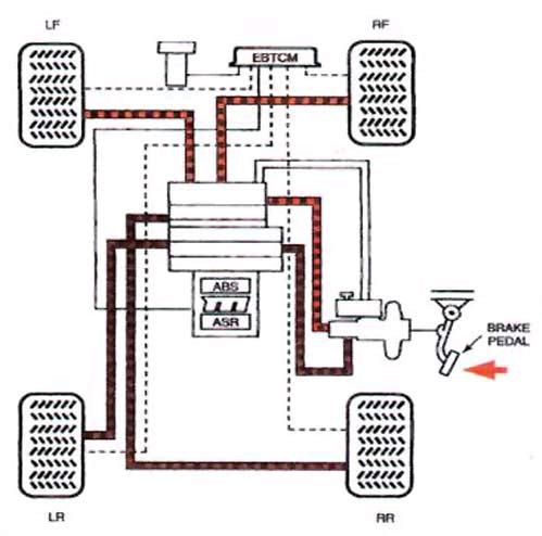
36 36 of 38 29/09/ :27 as the foundation brakes, or the base brakes. Anti-Lock Brake Operation Under normal braking conditions, the anti-lock portion of the brake system does not operate. The sensors continuously monitor wheel rotation and send signals to the anti-lock controller. When the brake pedal is pressed, fluid flows from the master cylinder, through the hydraulic modulator, and into the wheel cylinder or caliper, Figure The wheel speed sensors monitor wheel speed to determine whether any of the wheels are ceasing to turn (locking). If a wheel begins to lock up, the speed sensor reading alerts the ABS electronic control unit. When the ABS controller senses that a wheel is nearing lockup, it signals the appropriate solenoid valve in the hydraulic modulator to block the fluid passage between the master cylinder and the locking wheel assembly. When this occurs, pressure is trapped between the brake and the hydraulic modulator. Master cylinder fluid pressure cannot flow through the solenoid valve and the brake pressure at the affected wheel is held constant, Figure If the control module detects further lockup on the affected wheel, it will command the hydraulic modulator to decrease brake pressure to the appropriate wheel, Figure To accomplish this, the solenoid valve in the modulator moves to cut off fluid pressure from the master cylinder and allows brake fluid at the caliper to flow back into the accumulator, master cylinder reservoir, or pump intake. When this occurs, pressure at the wheel is decreased. With the piston type hydraulic modulator, the solenoid valves isolate the circuit from the master cylinder, and the pistons are moved to reduce pressure. Figure is a cut-away of one particular unit used to control fluid pressure to the front and rear brakes. After reducing pressure, the wheel will accelerate. When the wheel accelerates to a preset level, the control module will signal the hydraulic modulator to increase pressure. This causes wheel deceleration and the cycle begins again. When all the wheels are rotating normally, the solenoid valves in the modulator return to their original position and the foundation braking system takes over. At the same time, the modulator pump delivers any excess fluid back into the accumulator or master cylinder. Most anti-lock brake systems can repeat this cycle up to 15 times a second. Traction Control Systems To reduce wheel spin when accelerating on slippery surfaces, some vehicles are equipped with traction control systems, also called acceleration slip regulation. These systems are able to reduce engine power and operate the brake. Figure Schematics of four wheel anti-lock braking systems during normal (non-anti-lock mode) braking. A: Illustrates normal brake pressure traveling to the wheels. B: Fluid flow through the various valves of the system. Note that this system also includes an electronic traction control module. (Chevrolet)
37 37 of 38 29/09/ :27

38 . 38 of 38 29/09/ :27
Brake Systems. Introduction
 Brake Systems Figure 1. A Typical Brake System Introduction The brake system (Figure 1) is designed to slow and halt the motion of a vehicle. To do that, various components within a hydraulic brake system
Brake System Operation
 Brake System Brake System Operation Donald Jones Brookhaven College Master cylinder Brake lines Hydraulic valves Disc brakes Drum brakes Power assist unit Parking brake Antilock system Brake System Functions
Modern Auto Tech Study Guide Chapters 71 & 73 Pages Brake Systems 49 Points. Automotive Service
 Modern Auto Tech Study Guide Chapters 71 & 73 Pages 1369 1444 Brake Systems 49 Points 1. Automotive systems use to stop, slow or to hold the wheels from turning. Brake, Friction Brake, Fraction Brake,
Chapter 33 Fundamentals of Hydraulic and Air-Over-Hydraulic Braking Systems
 Chapter 33 Fundamentals of Hydraulic and Air-Over-Hydraulic Braking Systems Introduction Vehicle s braking system must meet the following requirements: To adequately and safely reduce a vehicle s speed,
Braking System Layout
 The Braking System The energy used to accelerate or move a vehicle from rest to a certain speed is called Kinetic i (moving) energy. To slow the vehicle down, this kinetic energy must be converted or changed,
SECTION 4A BRAKE SYSTEM TABLE OF CONTENTS
 SECTION 4A BRAKE SYSTEM TABLE OF CONTENTS Description and Operation... 4A-2 Braking System Testing... 4A-2 Hydraulic Brake System... 4A-2 Brake Pedal... 4A-2 Master Cylinder... 4A-2 Brake Booster... 4A-3
FUNDAMENTAL PRINCIPLES
 FUNDAMENTAL PRINCIPLES Fundamental Principles The most important safety feature of an automobile is its brake system. The ability of a braking system to provide safe, repeatable stopping is the key to
DESCRIPTION & OPERATION
 DESCRIPTION & OPERATION BRAKE BOOSTER Delco-Moraine Single Diaphragm A combined vacuum-hydraulic unit which uses a combination of intake manifold vacuum and atmospheric pressure to provide power assist.
BRAKE SYSTEM FUNDAMENTALS KARAN BHARDIYA ASSISTANT MANAGER -R&D ENDURANCE TECHNOLOGIES PVT.LTD. DISC BRAKES
 BRAKE SYSTEM FUNDAMENTALS KARAN BHARDIYA ASSISTANT MANAGER -R&D ENDURANCE TECHNOLOGIES PVT.LTD. DISC BRAKES AUTOMOTIVE BRAKING SYSTEMS How brakes manufacturing industry is different then rest of the automotive
FUNDAMENTAL PRINCIPLES
 Section 1 FUNDAMENTAL PRINCIPLES Lesson Objectives 1. Describe the cycle of heat as it applies to automotive brakes. 2. Explain the effect of heat transfer as it relates to brake fade. 3. Describe how
BRAKE SYSTEM Return To Main Table of Contents
 BRAKE SYSTEM Return To Main Table of Contents GENERAL... 2 BRAKE PEDAL... 10 MASTER CYLINDER... 13 BRAKE BOOSTER... 16 BRAKE LINE... 18 PROPORTIONING VALVE... 19 FRONT DISC BRAKE... 20 REAR DRUM BRAKE...
Disc Brake System Principles
 C H A P T E R 1 4 Disc Brake System Principles Chapter Objectives At the conclusion of this chapter you should be able to: KEY TERMS brake pads brake rotors caliper pistons composite rotor dust boot fade
C. Brake pads Replaceable friction surfaces that are forced against the rotor by the caliper piston.
 BRAKES UNIT 1: INTRODUCTION TO BRAKE SYSTEMS LESSON 1: FUNDAMENTAL PRINCIPLES OF BRAKE SYSTEMS I. Terms and definitions A. Brake fading Loss of brakes, usually due to heat. B. Brake lining Material mounted
INSTALLATION INSTRUCTIONS
 INSTALLATION INSTRUCTIONS DISC BRAKE CONVERSION KITS A121-1, A121-2, A121-3, A121-4 1967-69 Ford & Mercury Thank you for choosing STAINLESS STEEL BRAKES CORPORATION for your braking needs. Pleases take
DISC BRAKES. Section 4. Components and Operation of Disc Brakes. Disc Brake Assembly
 DISC BRAKES Components and Operation of Disc Brakes A disc brake assembly consists of a: cast iron disc (disc rotor) that rotates with the wheel. caliper assembly attached to the steering knuckle. friction
Hydraulic Brakes and Air-Over-Hydraulic Brake Systems
 Hydraulic Brakes and Air-Over-Hydraulic Brake Systems Objectives Describe the principles of operation of a hydraulic brake system. Identify the major components in a truck hydraulic brake system. Describe
A proportioning valve is used to regulate brake pressure between front and rear brakes. Rear brakes on all models are self-adjusting.
 Page 1 of 21 ARTICLE BEGINNING DESCRIPTION & OPERATION WARNING: For warnings and procedures regarding vehicles equipped with Anti- Lock Brake Systems (ABS), see ANTI-LOCK BRAKE SYSTEM article in the BRAKES
Module 6: Air Foundation Brakes
 Air Brakes Terms and Definitions Basic Components That Make Up Air Foundation Brakes Types of Air Foundation Brakes Parts of a Cam Foundation Brake Parts of a Wedge Foundation Brake Parts of a Disc Foundation
INSTALLATION INSTRUCTIONS
 INSTALLATION INSTRUCTIONS DISC BRAKE CONVERSION KIT A120-20, A120-21 1964 1 /2-66 Ford & Mercury Thank you for choosing STAINLESS STEEL BRAKES CORPORATION for your braking needs. Pleases take the time
MASTER CYLINDER. Section 2. Lesson Objectives
 MASTER CYLINDER Lesson Objectives 1. Explain the difference between conventional and diagonal split piping system and their application. 2. Describe the function of the compensating port of the master
Parking brake Mechanical brake acting on rear wheels
 11 Brake System 11.1 General SPECIFICATIONS EJTC0010 Master cylinder Type Tandem type I.D. mm(in.) 20.64 mm (0.813 in.) Fluid level warning sensor Provided Brake booster Type Vacuum Boosting ratio 4.0
Mopar 8 3/4 & 9 3/4 (Dana) Installation Instructions Rear Disc Conversion
 Installation Instructions Rear Disc Conversion") Mopar 8 3/4 & 9 3/4 (Dana) Installation Instructions Rear Disc Conversion This kit is for either Mopar 8 ¾ or Mopar 9 ¾ (Dana). This kit is designed to work with axles with either GM 5 x 4.75 Bolt Pattern
Mopar 8 3/4 & 9 3/4 (Dana) Installation Instructions Rear Disc Conversion This kit is for either Mopar 8 ¾ or Mopar 9 ¾ (Dana). This kit is designed to work with axles with either GM 5 x 4.75 Bolt Pattern
This file is available for free download at
 This file is available for free download at http://www.iluvmyrx7.com This file is fully text-searchable select Edit and Find and type in what you re looking for. This file is intended more for online viewing
BRAKE SYSTEM Article Text 1996 Toyota RAV4 For Copyright 1998 Mitchell Repair Information Company, LLC Wednesday, September 13, :30PM
 Article Text ARTICLE BEGINNING 1996 BRAKES Toyota - Disc & Drum RAV4 * PLEASE READ THIS FIRST * WARNING: For warnings and procedures regarding vehicles equipped with Anti-Lock Brake Systems (ABS), see
1999 Toyota RAV BRAKES Disc & Drum - Trucks & Vans
 DESCRIPTION & OPERATION 1999-2000 BRAKES Disc & Drum - Trucks & Vans WARNING: For warnings and procedures regarding vehicles equipped with Anti-Lock Brake Systems (ABS), see appropriate ANTI-LOCK article.
Brake System Diagnosis and Service
 AUMT 1310 - Brake System Diagnosis and Brake System Inspection Brake System Diagnosis and Donald Jones Brookhaven College Road test Hydraulic system Leaks Fluid condition Disc brakes Rotors and pads Drum
BRAKES. Section III REAR AXLE DATA AND SPECIFICATIONS HAND BRAKE CHRYSLER SERVICE MANUAL BRAKES 17
 BRAKES 17 There is no basic design change in the rear axle and sure grip differential except the larger diameter pinion shaft is now used on all models for 1959. The Service Procedures will remain the
TH!NK neighbor Section 2 Chassis Section 2 Chassis
 General Specifications... 2 Torque Specifications... 2 Description and Operation... 4 Wheel Alignment Angles... 4 Brakes... 4 Diagnosis and Testing... 6 Ball Joint Inspection... 6 Wheel Bearing Inspection...
Brake System Fundamentals Chapter 71 Name Date Period
 Brake System Fundamentals Chapter 71 Name Date Period Basic Brake System Matching 1. Metal tubing and rubber hose that transmit pressure to the wheel brake assemblies. 2. Mechanical system for applying
INSTALLATION INSTRUCTIONS
 INSTALLATION INSTRUCTIONS PERFORMANCE AT THE WHEELS KIT W120-22, W120-23 1964 1/2-69 MUSTANG Thank you for choosing STAINLESS STEEL BRAKES CORPORATION for your braking needs. Pleases take the time to read
US ARMY LIGHT WHEEL VEHICLE MECHANIC MOS 63B SKILL LEVEL 3 COURSE WHEELED VEHICLE BRAKING SYSTEMS SUBCOURSE NO. OD1008
 US ARMY LIGHT WHEEL VEHICLE MECHANIC MOS 63B SKILL LEVEL 3 COURSE WHEELED VEHICLE BRAKING SYSTEMS SUBCOURSE NO. OD1008 US Army Ordnance Center and School Five Credit Hours GENERAL The Wheeled Vehicle Braking
BRAKE SYSTEM Nissan 240SX DESCRIPTION BRAKE BLEEDING * PLEASE READ FIRST * BLEEDING PROCEDURES ADJUSTMENTS BRAKE PEDAL HEIGHT SPECS TABLE
 BRAKE SYSTEM 1990 Nissan 240SX 1990 BRAKE SYSTEMS Nissan Disc & Drum Axxess, Maxima, Pathfinder, Pickup, Pulsar NX, Sentra, Stanza, 240SX, 300ZX DESCRIPTION All brake systems are hydraulically operated
INSTALLATION INSTRUCTIONS
 INSTALLATION INSTRUCTIONS BIG ROTOR / CALIPER RELOCATION REAR KIT SUM-BK1423 1999-2009 GM 1/2 Ton Trucks & SUVs Thank you for choosing SUMMIT RACING for your braking needs. Pleases take the time to read
SECTION 4A HYDRAULIC BRAKES
 SECTION 4A HYDRAULIC BRAKES CAUTION: Disconnect the negative battery cable before removing or installing any electrical unit or when a tool or equipment could easily come in contact with exposed electrical
REMOVAL & INSTALLATION
 REMOVAL & INSTALLATION FRONT DISC BRAKE PADS 1. Raise and support front of vehicle. Remove wheels. Remove caliper bolt and brakeline bracket bolts. Pivot caliper aside. Remove pads and pad shim. Remove
INSTALLATION INSTRUCTIONS
 INSTALLATION INSTRUCTIONS FRONT DISC BRAKE CONVERSION KIT A129-2 1959-64 Full Size Chevrolet Car and FRONT DISC BRAKE CONVERSION KITS A129-3 & A129-4 1965-68 Full Size Chevrolet Car Thank you for choosing
INSTALLATION INSTRUCTIONS
 INSTALLATION INSTRUCTIONS PERFORMANCE AT THE WHEELS KITS W156-6 & W156-7 1965-74 MOPAR B & E BODY Thank you for choosing STAINLESS STEEL BRAKES CORPORATION for your braking needs. Pleases take the time
INSTALLATION INSTRUCTIONS
 INSTALLATION INSTRUCTIONS Disc Brake Spindle Kit SUM-BKA2447 1964-72 A-BODY 1967-69 F-BODY 1968-74 X-BODY Thank you for choosing SUMMIT RACING for your braking needs. Please take the time to read and carefully
CAUTION. 2. Remove the wheel cover or nut covers, as required. Remove the wheel and tire assembly.
 Стр. 1 из 16 REAR DRUM BRAKES CAUTION Brake shoes may contain asbestos, which has been determined to be a cancer causing agent. Never clean the brake surfaces with compressed air! Avoid inhaling any dust
Self Adjusting Disc Brakes
 Disc Brakes Four advantages of Disc Brakes to Drum Brakes 1) Resistance to heat fade 2) Resistance to water fade 3) Less of a tendency to pull 4) Automatically adjust to lining wear Self Adjusting Disc
Brake System H TX, H2.0TXS [B475]; H TX [B466] Safety Precautions Maintenance and Repair
![Brake System H TX, H2.0TXS [B475]; H TX [B466] Safety Precautions Maintenance and Repair](/thumbs/86/93834005.jpg "Brake System H TX, H2.0TXS [B475]; H TX [B466] Safety Precautions Maintenance and Repair") HMM180001 Brake System H1.5-1.8TX, H2.0TXS [B475]; H2.5-3.5TX [B466] Safety Precautions Maintenance and Repair When lifting parts or assemblies, make sure all slings, chains, or cables are correctly fastened,
HMM180001 Brake System H1.5-1.8TX, H2.0TXS [B475]; H2.5-3.5TX [B466] Safety Precautions Maintenance and Repair When lifting parts or assemblies, make sure all slings, chains, or cables are correctly fastened,
DESCRIPTION & OPERATION
 2004 BRAKES Disc - TSX DESCRIPTION & OPERATION WARNING: DO NOT use air pressure or a dry brush to clean brake assemblies. Avoid breathing brake dust. Use OSHA-approved vacuum cleaner for cleaning and collecting
REMOVAL & INSTALLATION
 REMOVAL & INSTALLATION REAR DISC BRAKE PADS Removal Raise and support vehicle. Remove wheels. Thoroughly clean outside of caliper to prevent dust and dirt from entering inside. Support caliper with a piece
A. Adapter A metal component that fastens the caliper to the knuckle. Some brake systems do not use adapters.
 BRAKES UNIT 5: DISC BRAKE DIAGNOSIS AND REPAIR LESSON 3: SERVICE DISC BRAKE CALIPERS I. Terms and definitions A. Adapter A metal component that fastens the caliper to the knuckle. Some brake systems do
Braking system. Basic requirement of a braking system
 Braking system The most vital factor in the running and control of the modern vehicle is the braking system. In order to bring the moving vehicle to rest or slow down, the energy of the vehicle processed
55-64 Full Size GM (Impala, Bel Air, etc.) This kit is for axles with a 3 3/8 spread center to center on the top two bolt holes (pictured left).
 This kit is for axles with a 3 3/8 spread center to center on the top two bolt holes (pictured left).") SUM-BK1624A Full Size GM Installation Instructions Rear Disc Conversion 55-64 Full Size GM (Impala, Bel Air, etc.) This kit is for axles with a 3 3/8 spread center to center on the top two bolt holes (pictured
SUM-BK1624A Full Size GM Installation Instructions Rear Disc Conversion 55-64 Full Size GM (Impala, Bel Air, etc.) This kit is for axles with a 3 3/8 spread center to center on the top two bolt holes (pictured
A /F/X Body Instruction Packet Rear Disc Conversion
 A /F/X Body Instruction Packet Rear Disc Conversion 64-72 A Body / 67-81 F Body / 62-74 X Body This kit is for axles with a 3 1/8 spread center to center on the top two bolt holes (pictured left). Rotor
BRAKE SYSTEM Toyota Celica DESCRIPTION DRUM BRAKES ADJUSTMENTS BRAKE PEDAL HEIGHT ADJUSTMENTS BRAKE PEDAL FREE PLAY ADJUSTMENTS
 BRAKE SYSTEM 1988 Toyota Celica 1988-89 BRAKES Toyota Celica, Corolla, MR2, Tercel DESCRIPTION The hydraulic brake system uses a tandem master cylinder with a vacuum power assist servo. MR2 and some Celica
SuperTrac. Axle. Service & Maintenance. Manual
 SuperTrac Axle Service & Maintenance Manual Table of Contents Page Exploded Views Section 1: General Information General Warnings Description of Axle Models Identifications Section 2: Installation Axle
INSTALLATION INSTRUCTIONS
 INSTALLATION INSTRUCTIONS REAR DISC BRAKE CONVERSION KIT A158 1994-97 Dodge Ram 1500 (2WD & 4WD) and REAR DISC BRAKE CONVERSION KIT A158-1 1998-01 Dodge Ram 1500 (2WD & 4WD) Thank you for choosing STAINLESS
Ford 8, 9 Small Bearing Installation Instructions Rear Disc Conversion
 Ford 8, 9 Small Bearing Installation Instructions Rear Disc Conversion This kit is for Ford 9 rear axles with the small (2.835 ) style bearing and Ford 8 rear ends. This kit is designed to work with axles
Installation Instructions
 Preparing your vehicle to install your brake system upgrade 1. Rack the vehicle. 2. If you don t have a rack, then you must take extra safety precautions. 3. Choose a firmly packed and level ground to
INSTALLATION INSTRUCTIONS
 INSTALLATION INSTRUCTIONS BIG ROTOR / CALIPER RELOCATION FRONT KITS SUM-BK1422, BK1423, BK1424 1999-2006 GM 1/2 Ton Trucks & SUVs Thank you for choosing SUMMIT RACING for your braking needs. Pleases take
Copyright 1998 Inter-Industry Conference On Auto Collision Repair v.4.0
 Uniform Procedures For Collision Repair BR11 Brakes 1. Description This procedure describes repair, replacement, and inspection requirements for collisiondamaged brake systems. 2. Purpose The purpose of
1. General Description
 General Description 1. General Description A: SPECIFICATION Front disc brake Rear disc brake Master cylinder Brake booster Brake line Model Other models WRX MT WRX AT STi Size 15 inch type 16 inch type
SECTION 4A HYDRAULIC BRAKES
 SECTION 4A HYDRAULIC BRAKES Caution: Disconnect the negative battery cable before removing or installing any electrical unit or when a tool or equipment could easily come in contact with exposed electrical
DISC BRAKE/DUAL MASTER CYLINDER CONVERSION. Tools, Equipment and Supplies Needed:
 Please take the time to read the enclosed instructions carefully. If you have any questions, call our Product Assistance personnel for clarification. It is important to note that these instructions contain
INSTALLATION INSTRUCTIONS
 INSTALLATION INSTRUCTIONS REAR DISC BRAKE CONVERSION KITS A112, A112-1 & A112-93 1979-93 FORD MUSTANG with 7.5" & 8.8" AXLES Thank you for choosing STAINLESS STEEL BRAKES CORPORATION for your braking needs.
CAUTION. Hydraulic Brakes. Braking Systems - Hydraulic
 Hydraulic Brakes Dexter offers several varieties of hydraulic trailer brakes. Your vehicle may be equipped with drum brakes or disc brakes. The hydraulic brakes on your trailer are much like those on your
BRAKE SYSTEM Article Text 1992 Mitsubishi Mirage For a a a a a Copyright 1998 Mitchell Repair Information Company, LLC Monday, April 01, :05AM
 Article Text ARTICLE BEGINNING 1992 BRAKES Chrysler Motors/Mitsubishi - Disc & Drum Chrysler Motors: Colt, Colt 200, Colt Vista, Ram-50, Stealth, Summit, Summit Wagon; Mitsubishi: Diamante, Eclipse, Expo/Expo
CAUTION. Hydraulic Brakes. Braking Systems - Hydraulic
 Hydraulic Brakes The hydraulic brakes on your trailer are much like those on your automobile or light truck. The hydraulic fluid from a master cylinder or actuation system is used to actuate the wheel
INSTALLATION INSTRUCTIONS
 INSTALLATION INSTRUCTIONS REAR DISC BRAKE CONVERSION KIT A126-1 1973-87 CHEVROLET 1/2 TON 2WD Thank you for choosing STAINLESS STEEL BRAKES CORPORATION for your braking needs. Pleases take the time to
SUSPENSION 2-1 SUSPENSION TABLE OF CONTENTS
 DN SUSPENSION 2-1 SUSPENSION TABLE OF CONTENTS page ALIGNMENT... 1 FRONT SUSPENSION - 4x2... 6 page FRONT SUSPENSION - 4x4... 14 REAR SUSPENSION... 23 ALIGNMENT TABLE OF CONTENTS page AND OPERATION WHEEL
TRADE OF HEAVY VEHICLE MECHANIC
 TRADE OF HEAVY VEHICLE MECHANIC PHASE 2 Module 5 Braking Systems UNIT: 1 Table of Contents 1. Learning Outcome... 1 1.1 Key Learning Points... 1 2.0 Health and Safety... 3 2.1 Principles of Braking...
INSTALLATION INSTRUCTIONS
 INSTALLATION INSTRUCTIONS DISC BRAKE CONVERSION KITS A120-4 & A120-5 1964-1/2-66 Ford & Mercury Thank you for choosing STAINLESS STEEL BRAKES CORPORATION for your braking needs. Pleases take the time to
INSTALLATION INSTRUCTIONS
 INSTALLATION INSTRUCTIONS FRONT DISC BRAKE CONVERSION KITS: A132-1, A133, A133-1 A134, A134-1 1968-73 MUSTANG/FORD Thank you for choosing STAINLESS STEEL BRAKES CORPORATION for your braking needs. Please
Automotive Chassis Systems James D. Halderman Sixth Edition
 Automotive Chassis Systems James D. Halderman Sixth Edition Pearson Education Limited Edinburgh Gate Harlow Essex CM20 2JE England and Associated Companies throughout the world Visit us on the World Wide
INSTALLATION INSTRUCTIONS
 INSTALLATION INSTRUCTIONS REAR DISC CONVERSION KIT A136-1 1976-86 AMC 20 AXLES WITH WARN FULL FLOATING AXLE CONVERSION Thank you for choosing STAINLESS STEEL BRAKES CORPORATION for your braking needs.
INSTALLATION INSTRUCTIONS
 INSTALLATION INSTRUCTIONS REAR DISC BRAKE CONVERSION KIT A125-3 1965-72 GM A-BODY 10 & 12 BOLT AXLES Thank you for choosing STAINLESS STEEL BRAKES CORPORATION for your braking needs. Pleases take the time
INSTALLATION INSTRUCTIONS
 INSTALLATION INSTRUCTIONS REAR DISC CONVERSION KIT A126-2 1988-98 C1500 2WD 10" REAR DRUM Thank you for choosing STAINLESS STEEL BRAKES CORPORATION for your braking needs. Pleases take the time to read
To study about various types of braking system.
 To study about various types of braking system INTRODUCTION The system is purely mechanical means & is independent of the hydraulic system which controls the brake normally. A brake commonly referred to
BRAKE SYSTEM TROUBLESHOOTING CHECKS AND ADJUSTMENTS MASTER CYLINDER BRAKE BOOSTER REAR BRAKE
 BR-1 BRAKE SYSTEM PRECAUTIONS TROUBLESHOOTING CHECKS AND ADJUSTMENTS MASTER CYLINDER BRAKE BOOSTER VACUUM PUMP FRONT BRAKE REAR BRAKE Drum Brake Disc Brake Parking Brake LOAD SENSING PROPORTIONING AND
Volkswagen New Beetle Brake System ABS, ABS/EDL 45 Anti-lock Brake System (ABS) (Page GR-45)
 (Page GR-45)") 45 Anti-lock Brake System (ABS) (Page GR-45) Anti-lock brake system (ABS) and anti-lock brake system with electronic differential lock (ABS/EDL) ITT Mark 20 IE Differences between ABS ITT Mark 20 IE and
45 Anti-lock Brake System (ABS) (Page GR-45) Anti-lock brake system (ABS) and anti-lock brake system with electronic differential lock (ABS/EDL) ITT Mark 20 IE Differences between ABS ITT Mark 20 IE and
INSTALLATION INSTRUCTIONS
 INSTALLATION INSTRUCTIONS REAR DISC CONVERSION KIT SUM-BK1414-X 1997-2004 JEEP WRANGLER (TJ) WITH DANA 44 AXLES (non-abs) Thank you for choosing SUMMIT RACING for your braking needs. Pleases take the time
12. FRONT WHEEL/FRONT BRAKE/
 12 4.5kgm 0.9kg-m 4.5kg-m 12-0 SERVICE INFORMATION... 12-1 HYDRAULIC BRAKE... 12-10 TROUBLESHOOTING... 12-2 FRONT SHOCK ABSORBER... 12-16 FRONT WHEEL... 12-3 STEERING HANDLEBAR... 12-19 FRONT BRAKE...
Hydro-Max Hydraulic Brake Booster and Master Cylinder. Technical Manual
 Hydro-Max Hydraulic Brake Booster and Master Cylinder Technical Manual * 5+0 Important Service Notes The information in this publication was current at the time of printing. The information presented in
INSTALLATION INSTRUCTIONS
 INSTALLATION INSTRUCTIONS POWER FRONT DISC CONVERSION KIT A126-7 1963-66 CHEVY C10 PICKUP NON-POWER FRONT DISC CONVERSION KIT A126-8 1963-72 CHEVY C10 PICKUP Thank you for choosing STAINLESS STEEL BRAKES
INSTALLATION INSTRUCTIONS
 INSTALLATION INSTRUCTIONS FX4 ELITE REAR DISC CONVERSION KITS WITH INTERNAL PARKING BRAKE A110-14, A111-25, A111-29 for FORD 8" & 9" REAR ENDS Thank you for choosing STAINLESS STEEL BRAKES CORPORATION
BRAKE BOOSTER. Section 5. Brake Booster. Construction. Single Diaphragm Booster
 BRAKE BOOSTER Brake Booster The brake booster is designed to create a greater braking force from a minimum pedal effort, using a difference in atmospheric pressure and the engine s manifold vacuum. It
INSTALLATION INSTRUCTIONS
 INSTALLATION INSTRUCTIONS REAR DISC BRAKE CONVERSION KIT A117-1, A117-2 1991-97 S10 PICKUP & BLAZER 1985-02 ASTRO AND SAFARI VAN Thank you for choosing STAINLESS STEEL BRAKES CORPORATION for your braking
AUTOMOTIVE ENGINEERING
 AUTOMOTIVE ENGINEERING UNIT 4 BRAKES & SUSPENSION TYPES OF BRAKES The two main types of friction brake are drum brake and disc brake. In both types a fixed (non-rotating) shoe or pad rubs against a moving
SD Bendix E-12 & E-15 Dual Brake Valve DESCRIPTION
 SD-03-6 Bendix E- & E-15 Dual Brake Valve TREADLE UPPER BODY ASSEMBLY PRIMARY DELIVERY ( ) 1 SECONDARY DELIVERY ( ) LOWER BODY ASSEMBLY MOUNTING PLATE PRIMARY SUPPLY ( SUP-1) PRIMARY SUPPLY ( SUP-) PRIMARY
INSTALLATION INSTRUCTIONS
 INSTALLATION INSTRUCTIONS FRONT DISC BRAKE CONVERSION KITS SUM-BK1200, SUM-BK1201, SUM-BK1202, SUM-BK1203 1964-72 A-BODY 1967-69 F-BODY 1962-74 X-BODY (NOTE: 62-64 X-BODY REQUIRES 5-LUG STEERING ARMS)
Brake Pad: Service and Repair Front PADS - BRAKE FRONT
 2005 Dodge Truck RAM 3500 4WD Pickup L6-5.9L DSL Turbo VIN C Page 1 Brake Pad: Service and Repair Front PADS - BRAKE FRONT REMOVAL 1. Raise and support vehicle. 2. Remove the wheel and tire assemblies.
INSTALLATION INSTRUCTIONS
 INSTALLATION INSTRUCTIONS REAR DISC BRAKE CONVERSION KITS SUM-BK1329-X, SUM-BK1329-99904, SUM-BK1330-X, SUM-BK1330-99904 CHRYSLER 8 3 /4", 9 3 /4" and 2-PIECE REAR AXLES Thank you for choosing SUMMIT RACING
35-1 GROUP 35 SERVICE BRAKES CONTENTS BASIC BRAKE SYSTEM... 35A ANTI-LOCK BRAKING SYSTEM (ABS)... 35B TRACTION CONTROL SYSTEM (TCL)...
... 35B TRACTION CONTROL SYSTEM (TCL)...") 35-1 GROUP 35 SERVICE BRAKES CONTENTS.............................. 35A ANTI-LOCK BRAKING SYSTEM (ABS)................... 35B TRACTION CONTROL SYSTEM (TCL)................... 35C 35A-2 GROUP 35A BASIC
35-1 GROUP 35 SERVICE BRAKES CONTENTS.............................. 35A ANTI-LOCK BRAKING SYSTEM (ABS)................... 35B TRACTION CONTROL SYSTEM (TCL)................... 35C 35A-2 GROUP 35A BASIC
INSTALLATION INSTRUCTIONS
 INSTALLATION INSTRUCTIONS FORCE 10 SPORT R1 REAR DISC CONVERSION KIT A126-50 2005-10 Chevrolet Silverado and GMC Sierra Thank you for choosing STAINLESS STEEL BRAKES CORPORATION for your braking needs.
INSTALLATION INSTRUCTIONS
 INSTALLATION INSTRUCTIONS INSTALLATION INSTRUCTIONS FOR A136 REAR DRUM TO DISC BRAKE CONVERSION KIT for 1970-75 Jeep, CJ SERIES with Dana 44 flanged axle Thank you for choosing STAINLESS STEEL BRAKES CORPORATION
SECTION 3D REAR AXLE TABLE OF CONTENTS
 SECTION 3D REAR AXLE TABLE OF CONTENTS General Description and Operation... 3D-2 Specifications... 3D-2 Fastener Tightening Specifications... 3D-2 Diagnostic Information and Procedures... 3D-3 Component
BRAKE E
 8-1 GENERAL...8-2 SPECIFICATIONS...8-6 COMPONENTS...8-7 FRONT BRAKE...8-12 DISASSEMBLY INSPECTION REASSEMBLY (Pn1, Cu2 3 TON SERIES)...8-12 DISASSEMBLY INSPECTION REASSEMBLY (Pn2 3 TON SERIES)...8-17 BRAKE
Dura Force Disc Brake System Service Manual
 TS 20809_a 3501 Shotwell Drive ISO/TS 16949:2002 Registered (PH): 937.743.8125 Franklin, OH 45005 www.waltheremc.com (FX): 937.743.8232 Table of Contents General Description 1 3 Fastener Torque Chart 4
GROUP 35A 35A-1 CONTENTS GENERAL DESCRIPTION... 35A-3 BASIC BRAKE SYSTEM DIAGNOSIS 35A-4 SPECIAL TOOLS... 35A-16 BRAKE PEDAL...
 35A-1 GROUP 35A CONTENTS GENERAL DESCRIPTION......... 35A-3 DIAGNOSIS 35A-4 INTRODUCTION TO DIAGNOSIS........................ 35A-4 DIAGNOSTIC TROUBLESHOOTING STRATEGY...... 35A-4 SYMPTOM CHART...................
INSTALLATION INSTRUCTIONS
 INSTALLATION INSTRUCTIONS REAR DISC BRAKE CONVERSION KIT A125-2 1955-70 FULL SIZE CHEVROLET Thank you for choosing STAINLESS STEEL BRAKES CORPORATION for your braking needs. Pleases take the time to read
Automobile section, showing different parts in detail. and miscellaneous devices.
 SECTION VII Nos. 97 112 Automobile section, showing different parts in detail. and miscellaneous devices. Hydraulic jack MECHANICAL MODELS 43 Section VII 97. Automobile engine starter. This device known
ASSEMBLY INSTRUCTIONS
 ASSEMBLY INSTRUCTIONS FOR FORGED SUPERLITE BIG BRAKE FRONT HUB KIT WITH 3.00 DIAMETER VENTED ROTOR 968-969 FORD MUSTANG (DISC BRAKE SPINDLE ONLY) PART NUMBER GROUP 0-950 WARNING INSTALLATION OF THIS KIT
REMOVAL & INSTALLATION
 REMOVAL & INSTALLATION REAR BRAKE CALIPER NOTE: For rear disc pad removal and installation, DO NOT disconnect brake hose from caliper (wire aside). Replace all pads on an axle if wear indicator on any
SD Bendix E-10PR Retarder Control Brake Valve DESCRIPTION. OPERATION - Refer to Figure 2
 SD-03-832 Bendix E-10PR Retarder Control Brake Valve MOUNTING PLATE SUPPLY 4 PORTS ELECTRICAL AUXILIARY DESCRIPTION TREADLE RETARDER CONTROL SECTION EXHAUST DELIVERY 4 PORTS FIGURE 1 - E-10PR RETARDER
YDRAULIC ISC BRAKES VERVIEW
 YDRAULIC ISC BRAKES VERVIEW 02 03 03 04 05 07 11 14 16 Introduction The Lever The Brake Hose The Caliper Closed and Open Systems Braking Power Four-Piston Calipers Heat and Fade Care INTRODUCTION FACTORS
Driver Driven. InputSpeed. Gears
 Gears Gears are toothed wheels designed to transmit rotary motion and power from one part of a mechanism to another. They are fitted to shafts with special devices called keys (or splines) that ensure
Module 11: Antilock Brakes Systems
 ÂÂ ABS Brake System Antilock Brake System Operation Principles of ABS Braking ABS Master Cylinder Hydraulic Control Unit Wheel Speed Sensors ABS Electronic Control Unit Terms and Definitions Purposes for