Problem Solving. Positive Displacement Pumps
|
|
|
- Abigail Hall
- 6 years ago
- Views:
Transcription

1 Problem Solving Positive Displacement Pumps IESE
2 Inside View This document has been produced to support pump users at all levels, providing an invaluable reference tool. It includes information on general Positive Displacement pump problems and their effect on rotary lobe pumps with suggestions as to probable causes and solutions. Main sections are as follows: 1. Introduction 2. Positive Displacement Pump Problems 3. Typical Problems and their effect on Rotary Lobe Pumps 4. How correct System Design and Installation can avoid potential problems 5. Problem Solving Table The information provided in this document is given in good faith, but Alfa Laval is not able to accept any responsibility for the accuracy of its content, or any consequences that may arise from the use of the information supplied or materials described.
3 Contents Page Section 1.0: Introduction 3 Introduction to problem solving Positive Displacement pumps. Section 2.0: Positive Displacement Pump Problems 5 Overview of pump problems typically found on Positive Displacement pumps. 2.1 Seal Leakage Inspect the entire seal Examine the wear track Examine the faces Signs of heat Inspect the seal drive Check the springs Check the elastomer Check for accidental rubbing External symptons of seal failure 17 Section 3.0: Typical Problems and their effect on Rotary Lobe Pumps 19 Detailed look at the most common problems advising causes and solutions. 3.1 No Flow Shaft Rotation Excessive Discharge Pressure and/or Change in Fluid Viscosity Inability to Prime Cavitation Gas Content Excessive Discharge Pressure Excessive Temperature and/or Rapid Temperature Change Excessive Noise or Vibration Pump Head Contact Summary 32 Section 4.0: How correct System Design and Installation can avoid 35 potential problems Advises guidelines relating to correct pump installation, system design and pipework layout. 4.1 Pipework Protection Operation Baseplate Foundations Coupling Alignment Pre-start up Checks 39 Section 5.0: Problem Solving Table 41 Provides summary of probable causes and solutions to the most common problems.
4
5 1.0 Introduction In most pumping systems, the pump is likely to be one of the most vulnerable components and systems frequently show the pump to be at fault regardless of what may be wrong. Upon investigation the likely causes of the problem are inadequate control of the pumped fluid or a change in operating requirements of which the system or pump is not capable of handling. Pumps that are correctly installed and operated within their design parameters will give typically long troublefree service of >10 years, unless on very arduous duties. In order to correctly identify the problem it is important to gather as much information relating to the process as follows: Reconfirm original duty requirements and/or system design. Check for any process changes i.e. pressure, temperature, fluid viscosity etc. Check whether the system was undergoing routine maintenance. How long did the pump operate before the problem. Check the appearance and condition of the pump internal components. Check when the pump was last serviced. Check for any changes in pump noise or vibration. This will save considerable time and effort in leading to the most appropriate solution. The most common problems associated with Positive Displacement pumps are shown herein with particular effects on our range of rotary lobe pumps. 3
6
7 2.0 Positive Displacement Pump Problems Typical pump problems include: No flow Excessive discharge pressure Excessive temperature and/or rapid temperature change Excessive noise or vibration Seal leakage These are common for all Positive Displacement pump types shown as follows: Pumps Positive Displacement Rotodynamic Rotor Reciprocating Multi-Stage Single Stage Multi-Rotor Single Rotor Diaphragm Plunger End Suction Double Entry Screw Piston Simplex Process Circumferential Piston Archimedian Screw Multiplex Rubber Lined Gear - Internal Flexible Member Submersible Gear - External Peristaltic General Rotary Lobe Vane Progressing Cavity 5
8 Typical causes are as follows: No flow Pump is not primed. The drive unit is turning pump in the wrong direction. Valves are closed or there is an obstruction in the suction or discharge pipework. The end of the suction pipework is not submerged. A strainer or filter is clogged. Insufficient Net Positive Suction Head available (NPSHa). A by-pass valve is open. Air leak in the suction pipe. Air ingress through (Packed) Gland. Pumping element is severely worn. Failure in drive train. No power to the pump. Pump speed too high. Pumped media viscosity is higher than expected. Excessive discharge pressure Valves are closed or there is an obstruction in the discharge pipework. A strainer of filter is clogged. Pumped media viscosity is higher than expected. Discharge pressure is higher than calculated. Excessive temperature Too high process temperature. Increase in ambient temperature. Excessive noise or vibration Pump and driver are misaligned. Pipework is not properly supported. Pumped media viscosity is too high. Pump is cavitating. Relief valve oscillating. Foundation or anchor bolts have become loose. Pumphead contact. Pump speed too high. Gas entrainment. Loss of shaft support (bearing failure). Pumped media contains unexpected abrasive particles. Poor pipework / system design. Seal leakage (see section 2.1 for further detail) Pumped media contains unexpected solids. Chemical corrosion / attack. Pump is cavitating. Too high discharge pressure. Too high temperature. Pump / shaft vibration. Incorrect fitting. Incorrect selection of seal materials. Pump allowed to run dry. Insufficient or no auxiliary flushing services. 6
9 Condition Effect on Positive Displacement Pump Types Gear Lobe Peristaltic Progressing Cavity Vane Dry Running Gear wear / failure None, providing gland area is flushed. Hose damage Stator failure - shedding into pumped media Vane damage Excessive Temperature Pumphead contact Pumphead contact Hose failure Stator failure Vane damage Excessive Discharge Pressure Gear / Shaft breakage Pumphead seizure Hose failure Stator failure Pumphead contact Cavitation Reduced flow / Gear wear / Erosion Reduced flow / Pumphead contact / Erosion Reduced flow / Hose damage Reduced flow / Stator failure Reuced flow / Vane damage Unexpected Hard Solids Pump seizure / Jamming Pumphead contact / Jamming Hose failure - shedding into pumped media Stator failure / Jamming Pump seizure / Jamming
10 2.1 Seal Leakage Mechanical seals are precision designed and manufactured products, yet one of the most common causes of failure in Positive Displacement pump types is due to the malfunction of its mechanical seal. By design mechanical seals are friction contact devices and can be subjected to a very wide range and often hostile operating environments. Selecting the correct mechanical seal is imperative to avoid any seal leakage i.e. mounting attitude, seal face combination and elastomer selection. To assist in identifying why a particular mechanical seal has leaked it is important to record as much information as possible: How long has the seal been in operation (months, days, hours)? Is the seal subject to continuous or intermittent running? Check for any process changes i.e. pressure, speed, temperature and pumped media details. Where is the seal leaking from? i.e. under sleeve, behind gasket, along shaft etc. How badly is the seal leaking? i.e. constant or variable, only when shaft is stationary. Check seal flush flow rate and pressure if single flushed or double flushed mechanical seals are used. Check for any pump cavitation and/or vibration. For solving any seal leakage problem it is advisable to adopt a systematic approach as follows: Inspect the entire seal Examine the wear track Examine the faces Signs of heat Inspect the seal drive Check the springs Check the elastomers Check for rubbing 8


11 2.1.1 Inspect the entire seal Do not try to solve a seal leakage problem by looking at only the parts that look important. Both the primary rotating and stationary seal faces should be inspected, as well as secondary seals such as O rings, cups or gaskets. The shaft sleeve and inside of the seal housing/casing should also be inspected. Look for any deposits, chips or broken components. Look for any wear debris near to seal faces Examine the wear track Normal wear pattern Cause: If leakage is present it is probably due to problems with elastomeric secondary seals. Replace both primary seal faces and secondary seals. Wide wear pattern Cause: This indicates that the pump shaft is running eccentrically due to being bent from misalignment, bearing failure, shaft deflection or severe pipe strain. Replace shaft and seals. Check shaft is correctly aligned, and check system pressures and alleviate any pipe strain. Off centre wear pattern Cause: This indicates that the seal faces are not running concentric to one another or the stationary face is not central in the gland area. Replace seals and install correctly by referring to the seal manufacturers fitting instructions. Non contact pattern Cause: This indicates that the rotary face is not mating with the stationary face. This can be due to incorrect installation, slipping of the drive mechanism or loss of anti-rotation devices. Install seals correctly by referring to the seal manufacturers fitting instructions and check that anti-rotation devices are present. 9


 and grind the hard face.")
12 2.1.3 Examine the faces Cracked ceramic face Cause: Over tightening or mishandling. Replace seals and install correctly by referring to the seal manufacturers fitting instructions and handle with care. Thermal shock Cause: Thermal stress is a common cause of fracture and usually occurs when the seal face is subjected to rapid temperature change i.e. after pumping hot media the pump/seal is cleaned with a cold cleaning fluid. Replace seals and investigate process and CIP temperature regimes and change accordingly. Example of crack in seal insert caused by thermal shock Heavy wear or scoring Cause: This often occurs with seals in severe abrasive service with the seal faces separating, letting in large particles between the seal faces. These particles then embed in the soft face (carbon) and grind the hard face. Replace seals with a hard face combination such as silicon carbide and/or provide a flush to the seal area. 10

.")

13 Coating removal Cause: This is due to incompatibility of the plating or base material with the pumped media causing chemical attack to part the different materials. Replace seals with different seal face material that is compatible with pumped media from seal manufacturer s recommendations. Chipping on outside diameter Cause: This is evident in soft seal face material (carbon) due to the solidification of pumped media on the face outside diameter causing breakage upon start up. Severe cavitation could also cause this problem. Replace seals and provide a flush to the seal area and/or eliminate any pump cavitation problems (see 3.1.4). Example of chipping on outside diameter of seal face Chipping on inside diameter Cause: This is evident in soft seal face material (carbon) due to abrasive particles in the pumped media damaging the seal face. Severe cavitation could also cause this problem. Replace seals with a hard face combination such as silicon carbide and provide a flush to the seal area and/or eliminate any pump cavitation problems (see 3.1.4). 11


14 Cracked carbon Cause: This is usually caused by over compression, vibration or the swelling of an elastomer on the inside diameter, putting the carbon in tension. Problem could also be mishandling. Replace seals and install correctly by referring to the seal manufacturers fitting instructions and handle with care. Check elastomers are compatible with the pumped media from seal manufacturer s recommendations. Pitting, blistering or corrosion Cause: Mechanical seals are selected for particular applications and should not be subject to these problems. However severe corrosion can occur if used on incompatible pumped media. Also this can occur when a poor grade of carbon is being used, or when retrofitted by someone other than the original manufacturer - here gases are trapped within the material which vaporise during operation, thereby allowing solidification of pumped media on the seal faces giving shearing and tearing effects. Replace seals with faces that are compatible with pumped media and/or an improved carbon grade. Corrosive attack of carbon can be eliminated by selecting carbons which are relatively binder free upon seal manufacturer s advice. Example of crevice corrosion on a stainless steel face Example of pitting corrosion on stainless steel 12


15 Worn spot in the stationary ring Cause: This usually occurs on soft face materials such as carbon or stainless steel but can arise in other materials under severe conditions. The usual cause of failure is a flush line being directed at the static face causing erosion. If the flush media contains abrasive particles and/or flow rate is excessive, the effect will be increased. Ensure flush is directed tangentially to the seal faces. Reduce flush flow rate. Eliminate any abrasive particles from the flush media. Change to hard face combination such as silicon carbide. An example of seal faces being subject to chemical attack An example of mechanical seal failure whereby the pumped media has been allowed to solidify on the seal faces causing leakage. Fitting a flushed mechanical seal arrangement will alleviate this problem Signs of heat If any discoloration of the seal parts is observed, then high friction between the seal faces has been created. Further evidence in O ring hardening and setting may support this. The seal faces will also show signs of excessive wear and possible heat distress in the form of thermal cracking. Cause: The most probable causes are dry running, flashing, or very poor face lubrication. Flashing being boiling of the fluid film on the seal faces. Other causes could be incorrect fitting of the seal causing high friction and thereby high temperatures within the seal or the pump is operating at excessive pressures or speed. Ensure seal does not run dry in the application. If this cannot be avoided a single seal with flush or a double seal with a barrier fluid should be considered ensuring proper lubrication of the seal. Ensure the seal is properly installed as per seal manufacturers fitting instructions. Ensure the pump operates at specified pressure and/or speed. 13
 Burnt o ring residues on the outer diameter 2.1.")
16 An example of a mechanical seal where the seal faces have been allowed to run dry The sealing surface is scored Burnt debris found on the inner diamete O ring is deformed (being axially moved from the fitted position close to the shaft step) Burnt o ring residues on the outer diameter Inspect the seal drive Mechanical seal designs all use some method to transmit torque from the shaft to the rotary seal face and mostly this is achieved by pins or grub screws. Seals are usually loose in torsion, that is, outside the pump you can twist them slightly before they engage. The pins or grub screws should be inspected for any signs of wear. Worn drive dogs or slots Cause: This can be caused by slip stick, where the two seal faces will stick together causing excessive stress on the drive pins. This stress is then transferred back to the seal face causing it to accelerate and then stick again. Instead of a smooth rotary motion, the seal face is being beaten around in its circular path. Slip stick is caused by a lack of face lubrication. The wear can also be the result from vibrations within the pump and could also be the result from a static face not being fitted squarely to the shaft causing axial movement of the rotary face. Ensure the seal is properly installed as per seal manufacturers fitting instructions. Ensure the pump operates at specified pressure and/or speed. A single seal with flush or a double seal with a barrier fluid should be considered ensuring proper lubrication of the seal. Ensure any vibrations are eliminated. Worn inner diameter of spring retainer Cause: This can be caused by the grub screws not being properly tightened during installation of seal. Also extreme shear stress between the seal faces due to pumped media properties has overcome the grip of the grub screws. The grub screws will show signs of severe wear. This failure is very often combined with longer periods of non-operation for the pump and poor cleaning cycles. Ensure the seal is properly installed as per seal manufacturers fitting instructions. For media having tacky properties, a single seal with flush or a double seal with a barrier fluid should be considered ensuring proper lubrication of the seal. Ensure proper cleaning cycle is applied within the process. 14


17 2.1.6 Check the springs Springs fail usually because of a combination of chemical attack and high stresses. Stress corrosion can occur for stainless steel springs used in certain pumped media containing either chlorine, bromine, iodine, fluorine ions or compounds of these elements. The free ions will attack the protecting chrome oxide layer of the stainless steel and while the oxide layer is being attacked the flaw will open up small cracks. If the oxide particles wedge into these cracks a sudden failure can occur. Other causes of failure can be: Within single seal configurations where a very small leakage can be detrimental for the spring as local concentrations will be high. Fatigue, which is the result from repeated load changes generated by repeated compression/decompression of the spring. This could be the result from a static face not being fitted squarely to the shaft. Ensure the concentration of corrosive elements on the spring is minimised by using either a single flush or a double seal arrangement. Change spring material to a more corrosion resistant material, such as Hastelloy. Ensure vibrations within the pump are minimised. Ensure axial movement is within specification. Ensure the seal is properly installed as per seal manufacturers fitting instructions Check the elastomer Swollen, sticky or disintegrating Cause: This is generally caused by chemical incompatibility with pumped media. Replace with different elastomer material that is compatible from seal manufacturer s recommendations. Hard or cracked Cause: This is generally caused by excessive heat and/or chemical attack. Usually the source of heat is the face or a metal to metal contact of two parts. Excessive face heat is caused by lack of lubrication and subsequent high friction. It could also be a sign that the pump has run dry. Ensure seal does not run dry in the application. If this cannot be avoided a single seal with flush or a double seal with a barrier fluid should be considered ensuring proper lubrication of the seal. Replace with different elastomer material that is compatible from seal manufacturer s recommendations. Compression set Cause: This is caused where the O ring has been unable to withstand the temperature of the pumped media - the O ring loses its roundness and becomes square in section. This may also occur if too much heat is generated at the seal faces. Reduce pumped media temperature and/or replace with different elastomer material that is compatible from seal manufacturer s recommendation and can withstand high temperature required. 15


18 Extruded Cause: This is caused by excessively high pressure and/or the size of the seal O ring groove being incorrect. As the o ring extrudes it will tear in the gap between shaft and seal ring. Replace elastomer and reduce system pressures. Also check that the O ring groove size is correct by referring to seal manufacturer. Example of O ring damaged by excessive pressure Cuts or nicks Cause: This is the most common failure and normally occurs during installation. By its nature elastomers slide on to the shafts with some interference and care should be taken when sliding new elastomers over any sharp edges, shoulders or old grub screw marks to avoid damage Check for accidental rubbing In a troubleshooting approach it is important to carefully inspect the shaft, seal and seal chamber if possible, looking for signs of rubbing. For pumps handling high temperature pumped media the rubbing of parts may only take place when the pump is hot. When cooled, the worn marks may become covered over and not be as noticeable. Some causes for accidental rubbing are: Flush or barrier fluid pipework entering the seal housing and extending into the seal area itself. Housings which do not pilot, slip down and hit the seal. Gaskets slip into the seal cavity. Rotary or stationary rings which do not pilot and come into contact with the shaft. Build up of scale in the seal area. Seal area not concentric with the shaft. Excessive shaft deflection caused by throttling the discharge or otherwise operating the pump at its wrong capacity or pressure. Ensure the shaft and seal area is per specification by checking with pump/seal manufacturers. Ensure the seal is properly installed as per seal manufacturers fitting instructions. Ensure operating conditions as those for which the pump/seal was selected? i.e. pressure, speed, temperature and product details. 16
19 Fretting on pump shaft/shaft sleeve Cause: Fretting corrosion is the result from a constant back and forth movement of the secondary seal over shaft/shaft sleeve causing permanent damage, appearing pitted or shiny bright. Fretting corrosion is most common for PTFE secondary seals. This will be the result from axial vibrations or pressure pulsations. Eliminate axial movement of the shaft. Eliminate pressure pulsations. Ensure hardness of shaft/shaft sleeve is per specification by checking with pump manufacturer. Consider hardening of the shaft/shaft sleeve for severe applications referring to pump manufacturer External Symptoms of Seal Failure Symptoms Seal squeals Carbon deposits Seal spits and sputters (popping) Seal drips steadily (heavy leakage is normally from the faces rather than the o rings) Pump/Shaft Vibration Possible Causes No seal lubrication. Lack of lubrication causes carbon to grind away. Liquid film vaporising/flashing between the faces. Liquid film vaporising/flashing between the faces. Primary: Faces not flat. Faces cracked, chipped or blistered. Distortion of seal faces for thermal or mechanical reasons. Secondary: Seals nicked or scratched during installation. Leakage of fluid under pump shaft sleeve. O rings have been compression set (hard and brittle). O rings subjected to chemical attack (soft and sticky). Incorrect seal materials specified. Seal Hardware: Spring failure. Erosion damage. Corrosion of drive mechanism. Shaft misalignment. Cavitation. Bearing failure. 17
20
21 3.0 Typical Problems and their effect on Rotary Lobe Pumps 3.1 No Flow The cause of this problem is normally due any of the following: Incorrect direction of shaft rotation. Excessive discharge pressure and/or change in fluid viscosity. Inability to prime Cavitation. Gas content Shaft Rotation This although obvious is often overlooked. The direction of flow is dictated by the direction of drive shaft rotation. Reversing the direction of rotation will reverse the flow direction. 19
22 3.1.2 Excessive Discharge Pressure and/or Change in Fluid Viscosity Rotary lobe pump performance on low viscosity fluids is greatly affected by excessive discharge pressure and/or changes in fluid viscosity. This is due to Slip, defined as the fluid lost by leakage through the pump clearances. The direction of slip will be from the high pressure to the low pressure side of the pump i.e. from pump outlet to pump inlet. The amount of slip is dependent upon several factors. Clearance Effect Increased clearances will result in greater slip. The size and shape of the rotor will be a factor in determining the amount of slip. Pressure Effect The amount of slip will increase as pressure increases which is shown below. For a given pump speed the amount of slip can be seen as the capacity at zero bar less the capacity at X bar. To overcome this amount of slip it will be necessary to increase the pump speed to maintain the capacity required. Viscosity Effect The amount of slip will decrease as fluid viscosity increases. The effect of viscosity on slip is shown below. The pressure lines will continue to move towards the zero pressure line as the viscosity increases. Rheological Effect 20
23 Poor pump performance may be attributed to an unexpected change in fluid viscosity. In some fluids the viscosity is constant regardless of the shear forces applied to the layers of fluid. These fluids are known as Newtonian fluids whereby at a constant temperature the viscosity is constant with change in shear rate or agitation. Newtonian Fluid Behaviour Viscosity Typical Newtonian fluids are: Water Beer Hydrocarbons Milk Mineral Oils Resins Syrups Shear rate However, there are many fluids which do not follow this linear law, these fluids are named Non- Newtonian fluids. Of these, Psuedoplastic fluids can have an affect on pump performance if not taken into consideration upon initial pump sizing. With Psuedoplastic fluids the viscosity decreases as shear rate increases, but initial viscosity may be so high as to prevent start of flow in a normal pumping system. Psuedoplastic Fluid Behaviour Viscosity Typical Psuedoplastic fluids are: Blood Emulsions Gums Lotions Soap Toothpaste Yeast Shear rate Sizing a pump and drive unit on the assumption that a fluid s at rest viscosity is the same as that under pumping conditions can result in an incorrectly sized pump and drive unit being applied, such that performance will not be as desired. For example, a liquid soap can have an at rest viscosity of cp but at the applied shear in a pump the applicable viscosity can be as low as 50 cp. If the pump was sized based upon the at rest viscosity of cp, the pump speed would be relatively slow. As the applicable viscosity in the pump is 50 cp, the result would be the pump not producing the expected design flow rate. Therefore to achieve the flow rate required it will be necessary to increase the pump speed thereby changing drive unit, or even replacing pump and drive unit with a larger model. 21
 a modest amount of air from the suction side of the pump to the discharge side of the pump.")


 in the inlet piping system.")
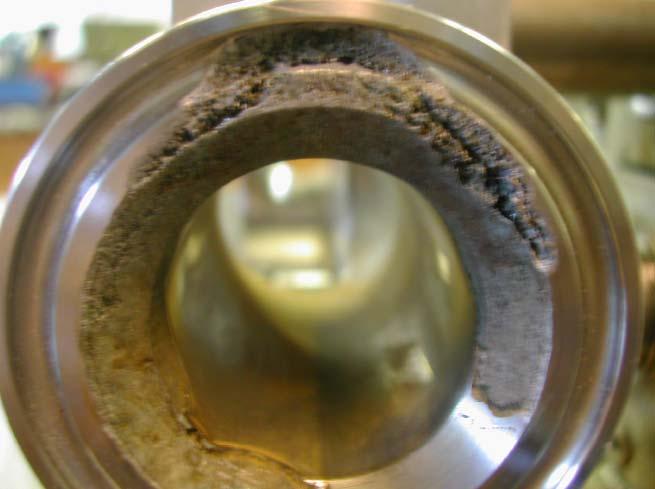
24 3.1.3 Inability to Prime Rotary lobe pumps may be classed as self priming. This means that within limits, they are capable of evacuating (pumping) a modest amount of air from the suction side of the pump to the discharge side of the pump. Filling the inlet system with fluid or at least filling the pump (wetted pumping elements) will make a major improvement in the pump s priming capability Cavitation The term cavitation is derived from the word cavity, meaning a hollow space. In pump terminology, cavitation is an undesirable vacuous space in the inlet port of the pump normally occupied by fluid. The lowest pressure point in a pump occurs at the pump inlet - due to local pressure reduction part if the fluid may evaporate generating small vapour bubbles known as vacuoles. These vacuoles are carried along by the fluid and implode instantly when they get into areas of higher pressure. Examples of small vapour bubbles Tri-lobe Rotor Pump Circumferential Piston Pump For all pump application problems, cavitation is the most commonly encountered. It occurs with all types of pumps, rotary, centrifugal or reciprocating, caused by insufficient system inlet pressure to the pump. This can be due to an inlet system restriction, excessive fluid viscosity or excessive pump speed. Inlet restrictions can include dirty or clogged inlet strainers, debris floating in the fluid supply that covers the inlet piping intake, or rags. If the fluid is cooler than design temperature, its viscosity may be too high causing excessive friction (pressure loss) in the inlet piping system. Cavitation is frequently accompanied by noise, vibration and significant increase in discharge pressure pulsation and/or loss of flow. If a pump is allowed to cavitate over long periods this will cause damage to the pumphead components and drive train. The surface of these components are typically perforated and pitted as material is eroded by implosive forces. 22


25 Typical cavitation effect on pump rotorcase cover. Severe cavitation will be evident even after a short operating period. Blemishes will appear on the rotorcase cover on the discharge side of the pump where vacuoles implode in the high pressure region. Ultimately this will erode the stainless steel cover as with the rotor. Typical cavitation effect on pump rotorcase. Cavitation can cause damage within the rotorcase as a consequence of shock loading the shafts. In extreme cases this can result in the rotor tips making contact with the casing as well as material erosion from imploding Suction Contact areas Discharge 23
 For")
26 Cavitation effect on pump rotor may result in rotor to rotor contact. Rotor flank showing effect of typical cavitation damage where minute particles of the rotor material are eroded by implosions of vacuoles Ensuring Sufficient Net Positive Suction Head (NPSH) For satisfactory pump operation the condition at the inlet of a pump is critical. The system on the inlet side of the pump must allow a smooth flow of fluid to enter the pump at a sufficiently high pressure to avoid cavitation. This is called the Net Positive Suction Head, generally abbreviated NPSH. It is critical that the net positive suction head available (NPSHa) in the system is greater than the net positive suction head required (NPSHr) by the pump. The value of NPSHa in the system is dependent upon the characteristic of the fluid being pumped, inlet piping, the location of the suction vessel, and the pressure applied to the fluid in the suction vessel. This is the actual pressure seen at the pump inlet. It is important to note, it is the inlet system that sets the inlet condition and not the pump. NPSHa is calculated as follows: NPSHa (metres) = Pressure action on Surface of liquid (Pa) ± Static suction _ Pressure drop _ head (h s ) (h fs ) Vapour pressure (Pvp) +ve -ve +ve -ve Where: Pa = Pressure absolute above fluid level (bar) h s = Static suction head (m) h fs = Pressure drop in suction line (m) Pvp = Vapour pressure (bar a) 24
27 Suggestions for avoiding cavitation Keep pressure drop in the inlet line to a minimum i.e. length of line as short as possible, diameter as large as possible, and minimal use of pipe fittings such as tees, valves etc. Maintain a static head as high as possible. Reduce fluid temperature, although caution is needed as this may have an effect of increasing fluid viscosity, thereby increasing pressure drop Gas Content Gas in the inlet pipework or entrained gas in the pumped media has the same impact on pump operation and creates the same symptoms as cavitation. This can occur under other circumstances such as a pump operating at an inlet pressure below local atmospheric pressure. In this instance it is quite likely that air is being drawn into the pipework through a loose pipe connection or pump casing joint, leaking inlet valve stem, defective or otherwise damaged joint gasket in the pipework system. 25

28 3.2 Excessive Discharge Pressure The design concept of the rotary lobe pump is to have no contacting parts in the pumphead. This requires having the shaft support bearings to be mounted outside of the pumphead, which results in an overhung load, caused by the rotors fitted to the shafts as shown below. Force due to pressure Support bearings Rotor Shaft Overhang length Outlet Inlet The effect of pressure on the rotors will cause shaft deflection, which could result in contact between rotors, rotorcase and rotorcase cover. To allow for this pressure effect, clearances are built into the pumphead between surfaces that may contact. For the Series S, X and D pump ranges there is only one pressure rating, which is the maximum differential pressure of the particular pump model. However, the Series A and G pump ranges have more than one pressure rating. Should the pressure rating be exceeded it is likely that as product wetted parts of the Series S, X and A pump ranges are predominantly manufactured from stainless steel any contact between rotating and stationary parts would cause galling and possible pump seizure. Example of rotor galling 26


29 Due to the positive action of the rotary lobe pump any restriction on the outlet side of the pump, either partial or total, may result in excessive pressure developing in the pumphead. To protect pump, drive unit and also limit pressure build up within associated process equipment it is advisable to install overload protection such as: Fitting an external spring-loaded pressure relief valve to the outlet side of the pump which will open under high pressure and allow fluid to return to the inlet side of the pump via a by-pass loop. or Fit the pump with an integral pressure relief valve. or Use proprietary electronic devices. Rotor tip contact will be initially visible on the discharge side of the rotorcase cover internal face. If overload continues pump is likely to be damaged beyond repair. Discharge Suction Rotor tip contact will be initially visible on the suction side of the rotorcase rear face. Discharge If overload continues pump is likely to be damaged beyond repair. Suction 27
30 If damaged areas on the rotorcase cover, rotors and rotor case have been polished to attempt repair, one area is usually forgotten, the inside diameter of the gland bushing. 28
31 3.3 Excessive Temperature and/or Rapid Temperature Change Changes in temperature will cause expansion upon heating or contraction upon cooling, to the pump rotorcase and gearcase components. The most significant result is the movement between shaft and gearcase/rotorcase allowing the rotors to move forward or backward in the rotorcase. With the rotors being allowed to move forward there will be a reduction to the front clearance. To compensate for this, the Series S, A, G and D pump ranges have increased clearances as shown below. Rotorcase Rotor Shaft Thermal expansion Standard clearance Standard rotor width Increased clearance Decreased rotor width The clearance is exaggerated to show the temperature Series S, A, G and D pumps are designed for three rotor temperature ratings: 70 C (158 F) 130 C (266 F) 200 C (392 F) For the Series X pump range, the design of the mechanical seal eliminates any contact between the fluid being pumped and the shaft. This results in the shaft not being subjected to the full temperature variation and therefore only one rotor temperature rating of 150 C (302 F) is necessary. It is imperative during any CIP operation that pumps are not subjected to rapid temperature changes i.e. hot to cold, as pump seizure can result from thermal shock. 29


32 Rotorcase with marks attributed to thermal shock. Here the shafts have contracted at a faster rate than the rotorcase, thereby causing contact with rear casing face. Rear rotor face with signs of rotorcase contact, indicative of rapidly decreasing temperature i.e. thermal shock - hot to cold. Cold to hot shock would cause rotors to contact rotorcase cover. 30
33 3.4 Excessive Noise or Vibration Excessive noise and/or vibration can be a symptom of many things such as: Cavitation Mechanical damage to pump assembly Misalignment of drive Harmonics with other elements of the system Cavitation, as previously described in 3.1.4, is especially true if the discharge pressure is fluctuating or pulsating. Mechanical causes of noise and vibration can include: Shaft misalignment Loose couplings Loose pump and/or driver mountings Loose pump and/or driver guards Worn or damaged pump driver Worn pump bearings Valve noise seemingly coming from the pump Valves, especially on the discharge side of the pump can sometimes go into a hydraulic vibration mode caused by operating pressure, flow rate and the valve design. Resetting or a change in an internal valve component is usually sufficient to solve the problem. 31
34 3.5 Pump Head Contact Summary For successful pump operation, rotary lobe pumps should operate without any contact of pump head components. Should contact occur, consideration should be given as to the position the rotor has had to move with respect to the rotorcase, rotorcase cover and/or other rotor to create the mark pattern as shown below. Also noted should be the factors that could have induced this relative movement i.e. pressure, temperature, shaft movement, casing movement, etc. Rotorcase Suction Discharge Rotor Contact Marks Rotor and Rotorcase Cover (full face). Rotor and bottom of Rotorcase (full face). Rotorcase cover (discharge side), Rotorcase (inlet side on back face and bore) and Rotor (tips tapering front to back and front and back face outer diameter). Rotor (all lobes on same flank). Rotor (all lobes on both flanks and some tips) and Rotorcase (corresponding with rotor tip marks) Rotorcase (bore and back face, more severe at outer diameter) and Rotor (tips and front and back face). Rotor (indentation in profile, in or near mesh). Rotorcase (indentation in bore). All product wetted surfaces (deterioration of surface). Possible Cause High temperature and/or rapid temperature increase. Loss of axial shaft retention. Loss of rotor retention. Insufficient front clearance. Rapid temperature decrease. Loss of axial shaft retention. Insufficient back clearance. High pressure. Loss of timing. Cavitation. Abrasive pumped media. Large hard solid. Large or hard solid. Corrosion. 32


35 Examples of galling caused by initial hard solid passing through pump 33


36 Example of corrosion on pump rotor. Example of corrosion on pump rotorcase port. Example of corrosion on pump rotorcase cover. 34
37 4.0 How correct System Design and Installation can avoid potential problems To ensure optimum pump operation it is important that any pump unit is installed correctly. When designing a pumping system consideration should be given to the pipework, pump protection and operation. Other factors such as baseplate mounting, coupling alignment and pre-start up checks should also be noted. 4.1 Pipework Have short straight inlet pipework. o This will reduce friction losses in the pipework, thereby improving the NPSH available. Avoid bends, tees and any restrictions close to either suction or discharge side of pump. Use long radius bends wherever possible. o This will minimise pressure losses and/or turbulence in the pipework. Keep pipework horizontal where applicable. o This will reduce possibility of air locks. Confirm the Net Positive Suction Head (NPSH) available from the system exceeds the NPSH required by the pump (see 3.1.4). o This is crucial for ensuring the smooth operation of the pump and preventing cavitation. Avoid suction lifts and manifold/common suction lines for two rotary lobe pumps running in parallel o This will prevent vibration or cavitation. Include eccentric reducers on suction lines. o This will minimise pressure losses and/or turbulence in the pipework. Avoid the use of blind tees. o This will avoid pressure pulsing and thereby noise and possible pump damage. Include for seal flushing pipework and/or media for heating/cooling jackets and saddles. o This will ensure satisfactory seal operation and/or maintain pumped media temperature in pumphead. All pipework must be supported. The pump must not be allowed to support any of the pipework weight and the moments and forces attributed to each particular pump should be taken into consideration. Plane X Plane Z Plane Y 35


38 Example of a poor pump installation, not adhering too many of the considerations advised 4.2 Protection Protect the pump against blockage from hard solid objects e.g. nuts, bolts, welding slag etc. o This will prevent possibility of pumphead seizure. Protect the pump from accidental operation against a closed valve by using relief valves, pressure switches or current limiting devices. o This will prevent over pressurisation. Ensure any automated valve systems do not permit directional switching valves to close or partially close. o This will avoid dead heading the pump on discharge. Fit valves, if two pumps are to be used on manifold/common discharge lines. o This will prevent over pressurisation. Fit suction and discharge monitoring devices. o This will assist in any diagnostics. Include for monitoring equipment in ATEX defined hazardous areas if applicable. o This will ensure safety with monitoring of seal temperature, pressure and flow. 4.3 Operation Do not subject rotary lobe pumps to rapid temperature changes. o This will prevent thermal shock and possible pumphead seizure. Ensure pumped media is maintained at the correct temperature. o This will avoid dramatic increase in viscosity leading to possible over pressurisation and/or cavitation. Try to allow at least 1 m for pump access. o This will ease maintenance all round the pump. Ensure fluid flow velocity is sufficient. o This will avoid pumped media settling out, thereby restricting flow and increasing pressure. 36


39 Example of a poor installation showing a short radius bend fitted directly on to the pump discharge connection. Good engineering practice would dictate to position the bend at least 10 pipe diameters away from the pump discharge connection. 4.4 Baseplate Foundations Pumps when supplied with a drive unit are normally mounted on a baseplate which have pre-drilled fixing holes to accept base retaining bolts. To provide a permanent rigid support for securing the pump unit, a foundation is required which will also absorb vibration, strain or shock on the pumping unit. Methods of anchoring the baseplate to the foundation are varied, they can be studs embedded in the concrete either at the pouring stage as shown below, or by use of epoxy type grouts. Alternatively mechanical fixings can be used. The foundation should be approx. 150 mm longer and wider than the baseplate. The depth of the foundation should be proportional to the size of the complete pump unit. For example, a large pump unit foundation depth should be at least 20 times the diameter of the foundation bolts. D = Diameter of foundation bolts The drawing above shows two typical methods for foundation bolt retaining. The sleeve allows for slight lateral movement of the bolts after the foundation is poured. Rag or waste paper can be used to prevent the concrete from entering the sleeve while the foundation is poured. A minimum of 14 days is normally required to allow the curing of the concrete prior to pump unit installation. 37

40 Example of poor installation where underside of base shows bolts only free standing on the floor. 4.5 Coupling Alignment Before the pump unit is installed it is important to ensure that the mounting surface is flat to avoid distortion of the baseplate, which may cause pump/motor shaft misalignment and pump/motor unit damage. Once the baseplate has been secured, the pump shaft to motor shaft coupling alignment should be checked and adjusted as necessary. This is achieved by checking the maximum angular and parallel allowable misalignments for the couplings as stated by the coupling manufacturer. 38
41 4.6 Pre-start up Checks Before the pump unit is started it is important to ensure that pre-start up checks are made as follows: Check that the pipework system has been purged to remove welding slag and any other debris. For purging purposes a bypass should be installed around the pump. Dependent upon the cleaning/purging velocity this may need to be done more than once. Minimum recommended velocity m/s. Check that all obstructions have been removed from the pipework and pump. Check that all the pump connections and pipework joints are tight. Check that pump and drive lubrication levels are correct. Check that seal flushing is connected if applicable. Check that all valves in the system are open. Check that all safety guards are in place. Check that pumped media is flowing in correct direction by starting and stopping pump. 39
42
43 5.0 Problem Solving Table The table shown offers probable causes and solutions to the most common problems encountered: 41
44 Problem No flow Under capacity Irregular discharge Low discharge pressure Pump will not prime Prime lost after starting Pump stalls when starting Pump overheats Motor overheats Excessive power absorbed Noise and vibration Rotor wear Syphoning Seizure Mechanical seal leakage Packed gland leakage Probable Causes Solutions Incorrect direction of rotation. Pump not primed. Insufficient NPSH available. Fluid vaporising in suction line. Reverse motor. Expel gas from suction line and pumping chamber and introduce fluid. Increase suction line diameter. Increase suction head. Simplify suction line configuration and reduce length. Reduce pump speed. Increase suction line diameter. Increase suction head. Simplify suction line configuration and reduce length. Reduce pump speed. Air entering suction line. Remake pipework joints. Strainer or filter blocked. Service fittings. Increase fluid temperature. Fluid viscosity above rated figure. Fluid viscosity below rated figure. Decrease pump speed. Check seal face viscosity limitations. Decrease fluid temperature. Increase pump speed. Cool the pumphead. Fluid temperature above rated figure. Reduce fluid temperature. Check seal face and elastomer temperature limitations. Fluid temperature below rated figure. Heat the pumphead. Increase fluid temperature. Clean the system. Unexpected solids in fluid. Discharge pressure above rated figure. Fit strainer to suction line. If solids cannot be eliminated, consider fitting double mechanical seals. Check for obstructions i.e. closed valve. Service system and change to prevent problem recurring. Simplify discharge line to decrease pressure. Gland over-tightened. Slacken and re-adjust gland packing. Gland under-tightened. Adjust gland packing. Seal flushing inadequate. Increase flush flow rate. Check that flush fluid flows freely into seal area. Pump speed above rated figure. Decrease pump speed. Pump speed below rated figure. Increase pump speed.
45 Problem No flow Under capacity Irregular discharge Low discharge pressure Pump will not prime Prime lost after starting Pump stalls when starting Pump overheats Motor overheats Excessive power absorbed Noise and vibration Rotor wear Syphoning Seizure Mechanical seal leakage Packed gland leakage Probable Causes Pump casing strained by pipework. Solutions Check alignment of pipes. Fit flexible pipes or expansion fittings. Support pipework. Flexible coupling misaligned. Check alignment and adjust mountings accordingly. Insecure pump driver mountings. Fit lock washers to slack fasteners and re-tighten. Shaft bearing wear or failure. Refer to pump supplier for advice and replacement parts. Worn un-synchronised timing gears. Refer to pump supplier for advice and replacement parts. Insufficient gearcase lubrication. Refer to pump supplier's instructions. Metal to metal contact of rotors. Check rated and duty pressures. Refer to pump supplier. Worn rotors. Fit new rotors. Check pressure setting and re-adjust if necessry. Rotorcase cover relief valve leakage. Rotorcase cover relief valve chatter. Rotorcase cover relief valve incorrectly set. Examine and clean seating surfaces. Replace worn parts. Check for wear on sealing surfaces, guides etc - replace as necessary. Re-adjust spring compression - valve should lift approx. 10% above duty pressure. Suction lift too high. Lower pump or raise liquid level. Pumped media not compatible with materials Use optional materials. used. No barrier in system to prevent flow passing Ensure discharge pipework higher than suction tank. back through pump. Pump allowed to run dry. Ensure system operation prevents this. Fit single flushed or double flushed mechanical seals. Fit flushed packed gland. Faulty motor. Check and replace motor bearings. Too large pumphead clearances. Fit new rotors and ensure clearances are as per recommendations. Rotors missing i.e. after service. Fit rotors.
46 How to contact Alfa Laval Contact details for all countries are continually updated on our website. Please visit to access the information direct.
NECO Pumping Systems
 INSTALLATION OPERATION & MAINTENANCE INSTRUCTIONS For Your NECO Pumping Systems Fuel Oil Transfer System THIS COMPLETELY ASSEMBLED, TESTED, PACKAGED SYSTEM IS OF THE HIGHEST QUALITY AND DESIGN. TO OBTAIN
TROUBLESHOOTING TABLE
 TROUBLESHOOTING TABLE TROUBLESHOOTING GUIDE GLOSARY OF TERMS VANE PUMPS NO FLOW, NO PRESSURE A) Is the pump rotating? a-1) Check if the coupling is rotating. If not, check the rotation of the electric
A pump is a machine used to move liquid through a piping system and to raise the pressure of the liquid.
 What is a pump A pump is a machine used to move liquid through a piping system and to raise the pressure of the liquid. Why increase a liquid s pressure? Static elevation a liquid s pressure must be increased
PUMPS STEAM TURBINES BUILDING & FIRE WASTEWATER SERVICE PUMP CLINIC 15 MECHANICAL SEAL DESIGN, OPERATION AND MAINTENANCE PROBLEMS
 PUMP CLINIC 15 MECHANICAL SEAL DESIGN, OPERATION AND MAINTENANCE PROBLEMS In my seminars I teach that mechanical seals fail prematurely because: The lapped faces open A seal component becomes damaged In
Table 6-1. Problems and solutions with pump operations. No Fluid Delivery
 Table 6-1. and solutions with pump operations No Fluid Delivery Fluid level in the reservoir is low. Oil intake pipe or inlet filter is plugged. Air leak in the inlet line prevents priming or causes noise
INSTALLATION, OPERATION AND MAINTENANCE MANUAL FOR THE
 INSTALLATION, OPERATION AND MAINTENANCE MANUAL FOR THE INSTALLATION, OPERATION AND MAINTENANCE MANUAL FOR THE ACCULOBE PUMP 1.0 Safety Information 2 1.1 Risk Assessment 4 2.0 Introduction 5 2.1 General
Penn Valley Pump Company Design Information for Double Disc Pumps
 Penn Valley Pump Company Design Information for Double Disc Pumps INTRODUCTION The Penn Valley Double Disc Pump utilizes a unique principle of operation whereby the discs perform the duties of pumping
Table of Contents Illustrations
 Principals of Operation Inspection & Troubleshooting Principles of Operation Inspection & Troubleshooting Form No. F 1031 Section 1000 Issue Date 09/19/94 Rev. Date 02/07/07 Table of Contents Illustrations
INSTALLATION AND SERVICE INSTRUCTIONS FOR 1008 AND 1010 SERIES PUMPS
 Service Instruction No. 11 INSTALLATION AND SERVICE INSTRUCTIONS FOR 1008 AND 1010 SERIES PUMPS GENERAL DESCRIPTION Pumping Principles Page 2 INSTALLATION Location Page 3 Proper Installation Page 3 Filter
Gauges, Sight Glasses and Vacuum Breakers
 Gauges, Sight Glasses and Vacuum Breakers Gauges, Sight Glasses and Vacuum Breakers Gauges Pressure gauges Pressure gauges should be installed in at least the following situations: Upstream of a pressure
Installation Vertical Pump: Installation 'CM' and 'CDM' Style: Operation:
 Installation Vertical Pump: Gusher vertical end suction pumps with integral shaft is easily installed and put into service. With the one piece shaft design there is no couplings to align, no shims or no
Hydraulic Maintenance & Troubleshooting. Content - Norman Kronowitz Presenter Jim Trinkle
 Hydraulic Maintenance & Troubleshooting Content - Norman Kronowitz Presenter Jim Trinkle Introduction Welcome to the CMA/Flodyne/Hydradyne s Hydraulic Troubleshooting presentation. We will introduce many
Operating & Maintenance Manual For Steam Conditioning Valve
 For Steam Conditioning Valve 1 Table of Contents 1.0 Introduction 3 2.0 Product description 3 3.0 Safety Instruction 4 4.0 Installation and Commissioning 5 5.0 Valve Disassembly 6 6.0 Maintenance 6 7.0
Table of Contents. 4. Before a New Turbocharger is Installed
 Table of Contents 1. Turbocharger Overview ------------------------------------------------------------------ 1.1. Definition -----------------------------------------------------------------------------
Before you go through this booklet, we request you to go through the following general instruction before commissioning your hydraulic systems.
 Hello, We are proud to be on your suppliers list. During few years we came to know that most of our customers are satisfied by Yuken Hydraulic Products but some of our customers had minor problems and
Commissioning & Maintenance Instructions. for. COBRA linear stepping motors
 Commissioning & Maintenance Instructions for COBRA linear stepping motors ACP&D Limited. 86 Rose Hill Road, Ashton-under-Lyne, Lancashire, OL6 8NS. Tel : +44 (0)161 343 1884 Fax: +44 (0)161 343 7773 e-mail:
DESIGN CONSIDERATIONS FOR ROTATING UNIONS SEALING TECHNOLOGIES
 DESIGN CONSIDERATIONS FOR ROTATING UNIONS SEALING TECHNOLOGIES Rotating unions convey fluid from a stationary supply line to equipment or a rotating tool. They are critical elements in a variety of applications
SERIES PC INSTRUCTION AND OPERATION MANUAL
 MEGGA SERIES PC INSTRUCTION AND OPERATION MANUAL Models PCT and PCF Close-coupled and frame-mounted single-stage horizontal end-suction pumps. WARNING: Read this manual before installing or operating this
FLUID POWER SEALING SOLUTIONS TROUBLESHOOTING GUIDE
 FLUID POWER SEALING SOLUTIONS TROUBLESHOOTING GUIDE POLYMER SEALS This section provides troubleshooting criteria for Chesterton s hydraulic and pneumatic sealing devices. It should be used only as a general
Troubleshooting Power Transmission Couplings
 Troubleshooting Power Transmission Couplings Introduction Power transmission couplings are used to connect two shafts that turn in the same direction on the same centerline. There are three principle types
INSTRUCTION MANUAL INTERNAL GEAR PUMP TITAN G-4124A SERIES=> FLANGED TITAN G-124A SERIES => FLANGED MODELS:
 INSTRUCTION MANUAL INTERNAL GEAR PUMP TITAN G-4124A SERIES=> FLANGED TITAN G-124A SERIES => FLANGED MODELS: G-H, G-HL, G-K, G-KK, G-L, G-LQ, G-LL, GLS, G-Q, G-QS 1 Contents Maintenance Thrust bearing adjustment
Introduction. Lubrication Related Failures. Gear Couplings. Failure Analysis All Types (Page 1 of 7)
") All Types (Page 1 of 7) Introduction A gear coupling serves as a mechanical device which connects shafts of two separate machines and accommodates small amounts of shaft misalignment. Commercial gear couplings
All Types (Page 1 of 7) Introduction A gear coupling serves as a mechanical device which connects shafts of two separate machines and accommodates small amounts of shaft misalignment. Commercial gear couplings
Module 6: Air Foundation Brakes
 Air Brakes Terms and Definitions Basic Components That Make Up Air Foundation Brakes Types of Air Foundation Brakes Parts of a Cam Foundation Brake Parts of a Wedge Foundation Brake Parts of a Disc Foundation
What is Wear? Abrasive wear
 What is Wear? Written by: Steffen D. Nyman, Education Coordinator, C.C.JENSEN A/S It is generally recognized that contamination of lubricating and hydraulic oils are the primary cause of wear and component
INSTALLATION, OPERATION AND MAINTENANCE INSTRUCTIONS
 INSTALLATION, OPERATION AND MAINTENANCE INSTRUCTIONS Contents Section 1. General Observations... 2 2. Operation... 4 3. Control During Operation... 5 4. Trouble Shooting... 6 5. Maintenance... 7 Please
 INSTRUCTIONS Your Ampco centrifugal pump is a rugged unit designed to provide years of low cost pumping service. There is a small amount of necessary care required to ensure you of this expected long service.
SERIES G3DB/AG3DB ELEVATOR
 TM INSTRUCTIONS AND PARTS LIST SERIES G3DB/AG3DB ELEVATOR WARNING This manual, and GENERAL INSTRUCTIONS MANUAL, CA-1, should be read thoroughly prior to pump installation, operation or maintenance. SRM00059
MAINTENANCE AND REPAIR INSTRUCTIONS
 MAINTENANCE AND REPAIR INSTRUCTIONS TYPE TH PUMPS Peerless Pump Company Indianapolis IN, 46207-7026 4849357 TABLE OF CONTENTS Maintenance Page 1 & 2 Disassembly Page 5 & 6 Impeller Clearance 3 Reassembly
OPERATION & MAINTENANCE MANUAL HANGZHOU FLYING TECHNOLOGY CO., LTD.
 CENTRIFUGAL PUMP ZPD6-25*7 OPERATION & MAINTENANCE MANUAL HANGZHOU FLYING TECHNOLOGY CO., LTD. CONTENTS 1. GENERAL (1) 2. NOMENCLATURE OF THE TYPE (1) 3. MAIN TECHNICAL SPECIFICATIONS RANGE (1) 4. STANDARD
INSTALLATION, OPERATION AND MAINTENANCE MANUAL FOR THE
 INSTALLATION, OPERATION AND MAINTENANCE MANUAL FOR THE RANGE OF PUMPS Page 0 INSTALLATION, OPERATION AND MAINTENANCE MANUAL FOR RTP TM ROTARY LOBE PUMPS. 1.0 SAFETY INFORMATION. 3 1.1 RISK ASSESSMENT RELATING
Synchronous Belt Failure Analysis Guide
 Synchronous Belt Failure Analysis Guide Contents Part 1: Common Causes of Belt Failure Normal Belt Wear and Failure Belt Crimp Failures Shock Load Part 2: Improper Belt Installation Tension Introduction
Test Which component has the highest Energy Density? A. Accumulator. B. Battery. C. Capacitor. D. Spring.
 Test 1 1. Which statement is True? A. Pneumatic systems are more suitable than hydraulic systems to drive powerful machines. B. Mechanical systems transfer energy for longer distances than hydraulic systems.
Series Base mounted pump. Installation and operating instructions
 Series 4030 Installation and File No: 40.80 Date: june 25, 2015 Supersedes: 40.80 Date: october 10, 2009 contents General 4 Inspection 4 Installation - Series 4030 base mounted Pump 4 1.0 Location 4 2.0
Instruction Manual. Rotary Lobe Pumps - OptiLobe ESE00528EN TD
 TD 246-034 Instruction Manual Rotary Lobe Pumps - OptiLobe ESE00528EN1 2007-09 EC Declaration of Incorporation The designating company Alfa Laval Eastbourne, Alfa Laval Ltd Company Name Birch Road, Eastbourne,
PRESSURE RELIEF VALVE: DISASSEMBLY, INSPECTION, and ASSEMBLY CONTENTS
 Page 1 of 35 PRESSURE RELIEF VALVE: DISASSEMBLY, INSPECTION, and ASSEMBLY CONTENTS 1. Overview 2. Disassembly of Valves with Liner Subs and press-in Bushing (Models 30525 and 30550). 2.1. Routine Disassembly
Background. The function of wear rings. Wear Rings. Throat Bushing
 Fluid processing industries have embraced the use of composite materials in pumps to reduce vibration, increase mechanical seal life and MTBR (mean time between repair), reduce the risk of seizure, increase
Routine Compressor Maintenance
 Establishing a regular, well-organized maintenance program and strictly following it is critical to maintaining the performance of a compressed air system. One person should be given the responsibility
Automotive manufacturing accelerometer applications
 Automotive manufacturing accelerometer applications Automotive manufacturing applications Spindle bearings Motor bearings Cooling tower motor and gearbox Stamping press motor and gearbox Paint booth air
FOR ROTARY TYPE TWIN GEAR. Pump Type: HGSX
 FOR ROTARY TYPE TWIN GEAR Pump Type: HGSX MODEL : CLIENT : PROJECT : P.O. NO. : SR. NO. : W.O. No. : MANUFACTURER : DEL Pd PUMPS & GEARS PVT LTD. HEAD OFFICE & WORKS : PLOT NO: 113, GIDC ESTATE, WADHWANCITY
Service Manual #40. Installation and Service Instructions 4000 Series Pumps
 Installation and Service Instructions 4000 Series Pumps General Description 4100/4120 Models Tuthill's 4100 and 4120 pumps are available in five sizes each, with nominal capacities ranging from 0.5 to
Failure Analysis for Plain Bearings
 Failure Analysis for Plain Bearings William Strecker, Kingsbury Tags: bearing lubrication The textbook cases of distress modes are especially useful in diagnosing problems prior to the damage that occurs
INSTALLATION, OPERATION AND MAINTENANCE MANUAL FOR THE. Range of Pumps
 INSTALLATION, OPERATION AND MAINTENANCE MANUAL FOR THE Range of Pumps Installation, Operation & Maintenance Manual For The MultiPump Range Of Rotary Lobe Pumps 1.0 Safety Information. 5 1.1 Risk assessment
Model Table of Contents. SERVICE & OPERATING MANUAL Original Instructions. Instructions Sheet:
 SERVICE & OPERATING MANUAL Original Instructions Instructions Sheet: 670989 Model 8324 Table of Contents Engineering Data and Temperature Limitations... 1 Performance Curve... 2 Dimensions... 3 Metric
VERTICAL MULTI-STAGES CENTRIFUGAL PUMPS
 Installation and Operating Instructions VERTICAL MULTI-STAGES CENTRIFUGAL PUMPS Models 1, 3, 5, 10, 15, 20, 32, 45, 64, 90, 120, 150 1. Model numbering and nameplate format 1.1 Model numbering Example:
Automotive manufacturing accelerometer applications
 Automotive manufacturing accelerometer applications The information contained in this document is the property of Wilcoxon Research and is proprietary and/or copyright material. This information and this
Model 8329 Table of Contents
 SERVICE & OPERATING MANUAL Original Instructions Instructions Sheet: 670991 Model 8329 Table of Contents Engineering Data and Temperature Limitations... 1 Performance Curve... 2 Dimensions... 3 Metric
POWER ASSISTED SYSTEM (POWER STEERING)
") POWER ASSISTED SYSTEM (POWER STEERING) TILT STEERING COLUMN 1. Tilt Steering Column A: TILT MECHANISM The steering wheel vertical position can be adjusted within a 38 mm (1.50 in) range by using the tilt
POWER ASSISTED SYSTEM (POWER STEERING) TILT STEERING COLUMN 1. Tilt Steering Column A: TILT MECHANISM The steering wheel vertical position can be adjusted within a 38 mm (1.50 in) range by using the tilt
PO Box 645, Stockton, Missouri, FAX superiorgearbox.com
 I000-7000-D0447-A 4/7/05 1 SAFETY PRECAUTIONS CAUTION Please read this entire document prior to operating the gear drive. Gear drive failure and / or injury to operators may be caused by improper installation,
OPERATION MANUAL. ALUMINUM Models. 316 S.S. Models NTG25 NOMAD TRANS-FLO AIR-OPERATED DOUBLE DIAPHRAGM PUMPS. A JDA Global Company. 1/14 rev.
 OPERATION MANUAL NTG25 NOMAD TRANS-FLO AIR-OPERATED DOUBLE DIAPHRAGM PUMPS ALUMINUM Models 316 S.S. Models A JDA Global Company 1/14 rev. 3 CAUTION SAFETY POINTS TEMPERATURE LIMITS: Neoprene -17.8 C to
Best Practice Variable Speed Pump Systems
 Best Practice Variable Speed Pump Systems Contents 1 Introduction 3 General Recommendations 4 2 Pumping Systems 6 3 Effects of Speed Variation 8 4 Variable Speed Drives 9 5 Financial Savings 11 Introduction
Fitting-removal and maintenance
 Fitting-removal and maintenance Fitting of bearings 136 General rules 136 Fitting principles 136 Hot fitting 137 Press fitting (or with anti-rebound hammer) 138 Adapter sleeves 139 Removal of bearings
The ELM Series Slurry Pump Installation and Operating Manual
 The ELM Series Slurry Pump Installation and Operating Manual Excellence Pump Industry Co., Ltd. SAFETY INFORMATION The following safety information relating to pump operation and maintenance should be
Operating and Maintenance Manual
 A World Leader in Diaphragm Pumps Operating and Maintenance Manual Thank you for purchasing a Comet Pump. Comet is an ISO 9001 manufacturer and as such produces quality products which are safe, efficient
Installation and Service Instructions. ST Series Pumps
 Installation and Service Instructions ST Series Pumps! WARNING READ MANUAL before operating or working on a Tuthill ST Series pump. Page 2 of 24 4/24/03 Table of Contents Page 4 Page 5 Page 5 Page 6 Page
OPERATION MANUAL NT50 NOMAD TRANS-FLO AIR-OPERATED DOUBLE DIAPHRAGM PUMPS. A JDA Global Company. 7/11 rev. 1
 OPERATION MANUAL NT50 NOMAD TRANS-FLO AIR-OPERATED DOUBLE DIAPHRAGM PUMPS A JDA Global Company 7/11 rev. 1 CAUTION SAFETY POINTS TEMPERATURE LIMITS: Neoprene -17.8 C to 93.3 C 0 F to 200 F Buna-N -12.2
Instruction Manual. Double Acting Hydraulic, Hollow Piston Cylinders RHD Series. Maximum Operating Pressure 700 bar
 Double Acting Hydraulic, Hollow Piston Cylinders RHD Series Maximum Operating Pressure 700 bar ABSOLUTE EQUIPMENT PTY LTD 2/186 Granite Street, GEEBUNG QLD 4034 Australia sales@absoluteequipment.com.au
kyproven Performance and Reliability
 . kyproven Performance and Reliability ky SRU Rotary Lobe Pump Application The SRU range of rotary lobe pumps has been designed for use on wide ranging applications within the Brewing, Dairy, Food, Pharmaceutical
PROCESS PUMPS (INDIA) PVT LTD
 PVT LTD") MANUAL: - M10 HORIZONTAL BPO METALLIC PUMP WITH EXTERNAL MECHANICAL SEAL (GROUP- III & IV) INSTALLATION, OPERATION AND MAINTENANCE MANUAL PROCESS PUMPS (INDIA) PVT LTD Plot No.86, III Phase, Peenya Industrial
MANUAL: - M10 HORIZONTAL BPO METALLIC PUMP WITH EXTERNAL MECHANICAL SEAL (GROUP- III & IV) INSTALLATION, OPERATION AND MAINTENANCE MANUAL PROCESS PUMPS (INDIA) PVT LTD Plot No.86, III Phase, Peenya Industrial
Operating Manual for Rotary Gear Pumps CMI, S.A. (Mendaro, Guipuzkoa, Spain)
") Operating Manual for Rotary Gear Pumps CMI, S.A. (Mendaro, Guipuzkoa, Spain) Pre-Installation 1. Choose a location that is easily accessible for pump servicing. Ensure adequate electrical service is available.
Operating Manual for Rotary Gear Pumps CMI, S.A. (Mendaro, Guipuzkoa, Spain) Pre-Installation 1. Choose a location that is easily accessible for pump servicing. Ensure adequate electrical service is available.
Troubleshooting the Transmission Hydraulic System
 Testing and Adjusting IT28F INTEGRATED TOOLCARRIER POWER TRAIN Testing And Adjusting Introduction Reference: For Specifications with illustrations, refer to SENR5974, IT28F Integrated Toolcarrier Power
MUELLER ECCENTRIC PLUG VALVE
 MUELLER INSTALLATION, OPERATING and MAINTENANCE INSTRUCTIONS 1 MUELLER System Design The life of the valve is dependent on its application, frequency of use and freedom from misuse. The properties of the
I N S T R U C T I O N M A N U A L
 I N S T R U C T I O N M A N U A L Oval Gear Positive Displacement Mechanical Flowmeters Models: 3 (080), 3 (080E), 4 (100), 4 (100E) NSW TEL: (02) 9939 0711 FAX: (02) 9939 0411 QLD/PNG TEL: (07) 3204 9166
Section 10 Chapter 17
 Section 10 Chapter 17 24 Valve, 8.3 Liter Engine Air Intake System Note: All coding used in the 8.3 Liter and 9 Liter engine manuals are Cummins engine codes. These engine codes have no meaning to New
kyproven Performance and Reliability
 . kyproven Performance and Reliability ky SRU Rotary Lobe Pump Application The SRU range of rotary lobe pumps has been designed for use on wide ranging applications within the Brewing, Dairy, Food, Pharmaceutical
Service Manual #67. Installation and Service Instructions 6000, 7000 & 8000 Series Magnetically Coupled Pumps
 Service Manual #67 Installation and Service Instructions 6000, 7000 & 8000 Series Magnetically Coupled Pumps Table of Contents Section Description Page 1 General Description 4 2 The Pumping Principle 5
Bearing Failure Analysis
 Bearing Failure Analysis The accurate diagnosis of a bearing failure is imperative to prevent repeated failures and their additional expenses. While performing failure analysis is commonly left to outside
INSTRUCTION, INSTALLATION, MAINTENANCE AND REPAIR MANUAL MODEL 3310
 SECTION 6 ITEM 3310 DATED JUNE 1, 2007 INSTRUCTION, INSTALLATION, MAINTENANCE AND REPAIR MANUAL 6 MODEL 3310 IMPORTANT NOTE TO INSTALLER: This manual contains important information about the installation,
VERTICAL MULTI-STAGE CENTRIFUGAL PUMPS
 Installation and Operating Instructions VERTICAL MULTI-STAGE CENTRIFUGAL PUMPS Models 1, 3, 5, 10, 15, 20, 32, 45, 64, 90 1. Model numbering and nameplate format 1.1 Model numbering Example: SBI / SBN
PROCESS PUMPS (INDIA) PVT LTD
 PVT LTD") MANUAL: - M12 HORIZONTAL BPO METALLIC PUMP WITH GLAND PACKING (GROUP- III & IV) INSTALLATION, OPERATION AND MAINTENANCE MANUAL PROCESS PUMPS (INDIA) PVT LTD Plot No.86, III Phase, Peenya Industrial Area,
MANUAL: - M12 HORIZONTAL BPO METALLIC PUMP WITH GLAND PACKING (GROUP- III & IV) INSTALLATION, OPERATION AND MAINTENANCE MANUAL PROCESS PUMPS (INDIA) PVT LTD Plot No.86, III Phase, Peenya Industrial Area,
V-Belt Installation, Maintenance & Storage Installation
 V-Belt Installation, Maintenance & Storage Installation 1. Check pulleys for rust, oil, grease, dust, dirt and other foreign materials. Clean the pulleys. Foreign materials accelerate belt wear and dramatically
application and are used in chemical injection systems (water
 Mechanical Equipment - Course 430.1 POSITIVE DISPLACEMENT PUMPS In the previous lesson it was explained that although centrifugal pumps have many operational and maintenance adva.ntages over positive displacement
REASONS YOUR BEARINGS WILL FAIL. Ritbearing CORPORATION
 12 REASONS YOUR BEARINGS WILL FAIL Ritbearing Things break. No matter what you do, there is always a chance that products you own will fail. The same holds true for bearings, but that doesn t mean that
Gear Drives. A third gear added to the system will rotate in the same direction as the drive gear Equal diameters = Equal number of teeth = Same speed
 Gear Drive Systems Gear Drives Gear Drive: Synchronous mechanical drive that uses gears to transfer power Gear: A toothed wheel that meshes with other toothed wheels to transfer rotational power Pinion
TECHNICAL SERVICE MANUAL INSTALLATION, START UP, TROUBLESHOOTING, SERIES SG-04, SG-05 & SG-07 spur gear PUMPS
 Electronic copies of the most current TSM issue can be found on the Viking Pump website at www.vikingpump.com TECHNICAL SERVICE MANUAL SECTION TSM 340 PAGE 1 OF 10 ISSUE G INSTALLATION, START UP, TROUBLESHOOTING,
kythe Optimum Choice for Ultra-Clean Processes
 . kythe Optimum Choice for Ultra-Clean Processes Alfa Laval SX Rotary Lobe Pump Application The SX range of rotary lobe pumps has been designed for use on wide ranging applications within the Pharmaceutical,
FUNCTION OF A BEARING
 Bearing FUNCTION OF A BEARING The main function of a rotating shaft is to transmit power from one end of the line to the other. It needs a good support to ensure stability and frictionless rotation. The
Clutch Diagnosis - Causes of Failure
 Clutch Diagnosis - Causes of Failure Guide Tube wear, Spline wear, Mainshaft Bearing wear Worn Flywheel Bearing, ridged or heat damaged Flywheel surface Worn/siezed Release Arm pivots, friction lining
Installation Instructions
 Installation Instructions Durametallic Double CRO Dual single coil spring friction drive for applications with water lubrication properties 1 Equipment Check 1.1 Follow plant safety regulations prior to
Installation and Service Instructions 1018, 1020, 1022, & 1024 Size Pumps
 Installation and Service Instructions 1018, 1020, 1022, & 1024 Size Pumps Excellence at work. Excellence in life. Table of Contents General Description 3 The Pumping Principle 3 Location 3 Proper Installation
Northern Pump A Division of McNally Industries, LLC
 Operation & Maintenance Manual for Northern 4900 Injection Operation & Maintenance Manual For Northern 4900 Injection Northern Pump A Division of McNally Industries, LLC 340 West Benson Avenue Grantsburg,
Instruction Manual. Rotary Lobe Pumps - OptiLobe ESE00528-EN Original manual TD
 Instruction Manual Rotary Lobe Pumps - OptiLobe TD 246-034 ESE00528-EN3 2014-06 Original manual Table of contents The information herein is correct at the time of issue but may be subject to change without
PROCESS PUMPS (INDIA) PVT LTD
 PVT LTD") HYDRODYNAMIC SEAL NON METALLIC PUMP INSTALLATION, OPERATION AND MAINTENANCE MANUAL PROCESS PUMPS (INDIA) PVT LTD Plot No.86, III Phase, Peenya Industrial Area, Bangalore 560058 Phone: 91-80-28395327/28
HYDRODYNAMIC SEAL NON METALLIC PUMP INSTALLATION, OPERATION AND MAINTENANCE MANUAL PROCESS PUMPS (INDIA) PVT LTD Plot No.86, III Phase, Peenya Industrial Area, Bangalore 560058 Phone: 91-80-28395327/28
PROMAG SR SERIES SEAL-LESS CENTRIFUGAL PUMPS
 PROMAG SR SERIES SEAL-LESS CENTRIFUGAL PUMPS INSTALLATION, OPERATION, AND MAINTENANCE INSTRUCTIONS TO OBTAIN THE BEST PERFORMANCE FROM YOUR PROMAG SR PUMP, PLEASE READ THE MANUAL CAREFULLY. Failure to
UNDERSTANDING TURBOCHARGERS THE ENGINEERS MANUAL TURBOCHARGER SERVICE & FAULT FINDING
 UNDERSTANDING TURBOCHARGERS THE ENGINEERS MANUAL TURBOCHARGER SERVICE & FAULT FINDING WHY TURBOCHARGE? Ever since the introduction of diesel engines the demand has always been for small engines capable
Installation and Service Instructions 1008 & 1010 Size Pumps
 Installation and Service Instructions 1008 & 1010 Size Pumps Excellence at work. Excellence in life. Table of Contents The Pumping Principle 3 Location 3 Proper Installation 3 Filter Protection 4 Startup
ISO 9001 CERTIFIED COMPANY INDUSTRIAL PUMPS. Installation & Operational Manual For BACK-PULL-OUT PUMP
 ISO 9001 CETIFIE COPANY Installation & Operational anual For BACK--OT P EX Assembly isassembly Erection Starting unning Stopping and aintenance Cautions in use of echanical Seal Stuffing Box and Packing
CYLINDER HEAD OVERHAUL
 ENGINE OVERHAUL PROCEDURES - GENERAL INFORMATION -2011 Mercedes-... Page 1 of 20 CYLINDER HEAD OVERHAUL * PLEASE READ THIS FIRST * Examples used in this article are general in nature and do not necessarily
PRESSURE CABINETS PROBLEM CAUSE SOLUTION
 BLAST CABINET TROUBLESHOOTING Page 1 PRESSURE CABINETS 1. Poor Visibility. Motor rotating backwards. The motor should rotate as indicated by the arrow on the housing. If it does not rotate in the proper
Positive Displacement Rotary Lobe Pumps
 Positive Displacement Rotary Lobe Pumps Three Great Lines G Series: General Use R Series: Sludge, Mud & Slurries C Series: Chemicals & Corrosives Is a LobeStar rotary pump right for you? 1). Are you pumping
PR Series Positive Rotary Pumps
 PRSM PR Series Positive Rotary Pumps Models PR, PRE, and PRED CONTENTS Thank you for purchasing a Tri-Clover Product! This manual contains disassembly and assembly instructions, maintenance procedures,
DuPont Vespel CR-6100 APPLICATION AND INSTALLATION GUIDE FOR CENTRIFUGAL PUMP STATIONARY WEAR PARTS
 DuPont Vespel CR-6100 APPLICATION AND INSTALLATION GUIDE FOR CENTRIFUGAL PUMP STATIONARY WEAR PARTS Fluid processing industries have embraced the use of composite materials in pumps to reduce vibration,
Impeller Replacement
 Impeller Replacement Threaded Shaft Frame Mount H 806 Clockwise Rotation Volute shown. 1149 0794 1 Unfasten hardware holding volute to bracket. Remove volute to expose impeller. Peel off old volute gasket
Bearings. Rolling-contact Bearings
 Bearings A bearing is a mechanical element that limits relative motion to only the desired motion and at the same time it reduces the frictional resistance to the desired motion. Depending on the design
Topic 1. Basics of Oil Hydraulic Systems
 Topic 1. Basics of Oil Hydraulic Systems Fluid power Fluid power is the technology that deals with the generation, control and transmission of forces and movement of mechanical element or system with the
LECTURE 30 to 31 ACCESSORIES USED IN FLUID POWER SYSTEMS FREQUENTLY ASKED QUESTIONS
 LECTURE 30 to 31 ACCESSORIES USED IN FLUID POWER SYSTEMS FREQUENTLY ASKED QUESTIONS 1. Explain the two types of the leakages in hydraulic system. In what way do they affect the performance of a fluid system?
INSTALLATION, OPERATION AND MAINTENANCE MANUAL FOR THE
 INSTALLATION, OPERATION AND MAINTENANCE MANUAL FOR THE RANGE OF PUMPS Installation, Operation & Maintenance Manual For The MultiPump Range Of Rotary Lobe Pumps 1.0 Safety Information 4 1.1 Risk assessment
BUTTERFLY VALVE WITH WELDED ENDS INSTALLATION AND MAINTENANCE MANUAL
 BUTTERFLY VALVE 31300 SERIES INSTRUCTIONS FOR INSTALLATION, USE AND MAINTENANCE 1. Overview Read these instructions carefully before starting the valve installation and start-up work. Safe keep the instructions
Service Instruction ENGINE COMPONENTS, INC.
 Title: Service Instruction S.I. No.: 89-5-1 Page: 1 of 5 Issued: 05/05/89 Revision: 1 (09/01/01) Technical Portions of FAA DER Approved. FAILURE OF ENGINE TO START 27 points 1. Lack of fuel 2. Ignition
SERIES FE MAGNETIC COUPLED PUMPS
 SERIES FE MAGNETIC COUPLED PUMPS Refer to Bulletin P-518 O-2804 TABLE OF CONTENTS Description Page Number Important Information...3 Chemical Reaction Disclaimer...3 Safety Precautions...3 Installation/Operation
MAINTENANCE MANUAL FOR THERMOSTATIC TEMPERATURE REGULATING VALVE TRAC STYLE P
 MANUAL NUMBER P-EFS-1 MAINTENANCE MANUAL FOR THERMOSTATIC TEMPERATURE REGULATING VALVE TRAC STYLE P TRAC Regulator Company Inc. 160 South Terrace Avenue Mount Vernon, New York USA 10550-2408 Phone: (914)