Table of Contents. Parts Overview 1-3. Tools Needed 4. Recommended Service Parts 4. Gas Fire-Up Check List 5. Troubleshooting Flow Chart 6-9
|
|
|
- Eustace French
- 6 years ago
- Views:
Transcription
1 GreenSmart TM 2 Parts Overview & Troubleshooting 6/13/2014


2 Table of Contents Section Page Number(s) Parts Overview 1-3 Tools Needed 4 Recommended Service Parts 4 Gas Fire-Up Check List 5 Troubleshooting Flow Chart 6-9 Reference Diagrams Wiring Diagrams Quick Start Information If the issue is pilot ignition or flame rectification, check the pilot assembly first. The appliance should have a PSE pilot assembly. This assembly will improve pilot ignition and flame rectification. Next, identify the version of IFC before you begin troubleshooting. The IFC will be marked with a silver numeral on both ends. An updated IFC will provide the necessary power for the spark electrode and flame sensor. Base IFC s (shown on left) should be a number 4 or higher Remote IFC s (shown on right) should be a number 5 or higher
 Used on all GreenSmart appliances Allows for gas to become present at pilot and burner Pilot")

 o")
 (250-02664) Central processor (brain) for all base GreenSmart appliances Provides the spark and monitoring of")
3 Travis Industries, Inc Harbour Pointe Blvd. SW Mukilteo, WA Gas Control Valve ( ) Used on all GreenSmart appliances Allows for gas to become present at pilot and burner Pilot adjustment screw Pressure taps (incoming and outgoing) Electrical spades for voltage testing (orange, green) Manual High/Low regulator for pressure adjustments o Note: Some inserts, deluxe fireplaces, and HO units come standard with NG stepper motor. Please refer to manual for details. Split Flow (Comfort Control) Valve ( ) Used on all GreenSmart appliances (except 616 DF) Allows on/off control of a portion of the burner In a base system, batteries needed to function Pilot Assembly Used on all GreenSmart appliances PSE Pilot Assembly o 2-way assembly ( ) o 3-way assembly ( ) DVL, 33 DVI 864 HO & Cypress only o 3-way assembly ( ) 616 and 616 DF only o Spark Rod ( ) Base Integrated Fireplace Control (IFC) ( ) Central processor (brain) for all base GreenSmart appliances Provides the spark and monitoring of the pilot Controls operation of the gas valve Contains red led light for diagnostics Protected by 3.15 amp fuse 1
 Used to turn main burner ON/OFF Switch has 2 male")
 Opens and closes the split flow")
 Switches between standing pilot and continuous")
4 Travis Industries, Inc Harbour Pointe Blvd. SW Mukilteo, WA Main Burner Switch ( ) Used to turn main burner ON/OFF Switch has 2 male spades, use one top and one bottom as illustrated Used only in base systems Discarded when unit is upgraded to GS remote Main Burner Comfort Control Switch ( ) Opens and closes the split flow (comfort control) valve for rear or outside burner functions Used only in base systems Discarded when unit is upgraded to GS remote IPI/CPI Switch ( ) Switches between standing pilot and continuous pilot Used on base GreenSmart systems Discard when unit is upgraded 2
 (250-02662) Incoming Power connected to board Receiver built in Accent lights and Blower control Stepper Motor and")
 Sends signal to receiver On/Off button Thermostat button Up and Down arrow key Mode button IPI/CPI activation Blower and Light modulation")
 (250-01463) Used in GS remote upgrade kit Electronically modulates burner up and down Works in conjunction with remote")
5 Travis Industries, Inc Harbour Pointe Blvd. SW Mukilteo, WA Remote Integrated Fireplace Control (IFC) ( ) Incoming Power connected to board Receiver built in Accent lights and Blower control Stepper Motor and Comfort Control connect to board Protected by 3.15 amp fuse Wall Mounted Remote ( ) Sends signal to receiver On/Off button Thermostat button Up and Down arrow key Mode button IPI/CPI activation Blower and Light modulation Amber Back Light Used in upgraded GreenSmart remote units 3 AAA batteries Stepper motor Natural Gas (NG) ( ) Natural Gas (NG) ( ) o Used only on single burner units: 3615, 4415, 6015, 564DF, and 616DF Liquid Propane (LP) ( ) Used in GS remote upgrade kit Electronically modulates burner up and down Works in conjunction with remote transmitter o Note: Some inserts, deluxe fireplaces, and HO units come standard with NG stepper motor. Please refer to manual for details. Battery Holder ( ) Battery Back up 4 AA batteries On/Off/Remote switch Operates burner when no remote PRG button for programming the remote 3
6 Travis Industries, Inc Harbour Pointe Blvd. SW Mukilteo, WA Tools needed: 1. Multimeter 2. Gas pressure gauge 3. Gas leak detector 4. Phillips screwdriver#2 5. Small flat blade screwdriver 6. 1/4 & 5/16 nut drivers 7. Needle nose pliers 8. Slip joint pliers 9. Outlet analyzer 10. 3/4 & 7/8 open end wrenches 11. #20 torque driver 12. Test cord for lights and fan ( ) Recommended Parts List for GreenSmart2 service: 1. PSE Pilot Assembly (2-way , 3-way , and way )) 2. Base IFC ( ), Remote IFC ( ) 3. Battery Holder ( ) and 4-AA batteries 4. Wall Mounted Remote ( ) and 3-AAA batteries 5. Switches Main burner ( ) Comfort Control ( ) IPI/CPI ( ) 6. Regulator NG ( ) & LP ( ) 7. Stepper Motor NG ( ) & LP ( ) 8. Sit Gas Valve ( ) 9. Wiring harnesses Main harness used on all GS2 units (except 430/616) Main harness for 430/ Short Power Supply harness used on DVS/31DVI, 616, and 21TRV Long Power Supply harness used on all GS2 units except those noted above Remote Upgrade harness used on all upgraded GS2 units Fan/Light harness that plugs into IFC Amp fuses for lights and fan ( pack) Amp fuses for IFC ( pack) 4
7 5
8 PILOT IGNITION Turn Main Burner Switch To ON, Wait Seconds. IS SPARK SEEN AT PILOT? 1. Is the Intergrated Fireplace Control (IFC) in lockout - 3 RED FLASHES every few seconds. Turn off for 5 seconds and back on. 2. Does stove have a PSE pilot upgrade kit If not install kit. 3. Check spark rod. Is spark seen at the base? If so porcelain is cracked. Replace ignitor. 4. Check ignitor wire at IFC. Is spark seen there? If so check to make sure insulation tube is down all the way on the wire. 5. Check to see if batteries are in properly. 6. Check battery voltage at the battery molex. If voltage is below 4.8 replace the batteries. RED and Black Wires (See Diagram B) 7. Verify appliance is connected to grounded circuit properly (use outlet analyzer). 8. Check inline voltage - Black to L and polarity. - White to N (See Diagram A) - Green to ground unit. - Check Fuse (3.15 amp) on IFC 9. Check to see if the unit is grounded on IFC to base. DOES THE PILOT LIGHT? DOES PILOT BURN BUT IGNITOR CONTINUES TO SPARK? SEE NEXT PAGE. 1. Check voltage to ON/OFF switches on Green and White wire. You should have 3+ volts DC with switch in the OFF position (BASE ONLY). If no, replace IFC. 2. Check ON/OFF switch for continuity. No continuity, 3. replace switch (Base Only). 3. Check voltage to Continuous pilot switch. Blue and White wire should have 3+ volts DC with the switch in IPI position. On upgrade, unplug jumper to test. If no voltage, replace IFC. 4. Check continuity of continuous pilot switch. Continuity, switch is good, No Continuity, replace switch. 5. Verify main harness connection to IFC (X5). (See Diagram K) 6. Check to see if igniter wire connected to IFC (X2). (See Diagram K) 7. Check continuity of the pilot coil. Continuity within range = good value. No continuity or outside of range = bad value. Replace valve. (See Diagram C) 8. Check that the orange wire is connected to the pilot coil. 9. Check voltage at the pilot coil. Should be 5 volts 12. DC for 1 sec. After 1 sec. voltage will drop to.9 volts. 12. No voltage. Replace IFC. (See Diagram D) 10. Check incoming gas pressure. Is gas turned on? (See Diagram H) 11. Check continuity of ORANGE wire to ground - no continuity OK. If continuity replace wiring harness TE: IFC can continue to spark up to 60 seconds after pilot is lit. This can be normal as pilot establishes. 1. Is flame sensor being hit by pilot flame? If not, adjust pilot. 2. Is the flame sensor wire connected to the IFC and grounded? If not, connect it (X3). (See Diagram K) 3. Check log placement. 4. Check continuity of flame sensor. 6
9 BURNER IGNITION DOES THE PILOT FLAME ACT RMAL? 1. Identify if the pilot activity is turbulance or starvation. Adjust Intake and Exhaust Restrictors as needed. 2. Does the pilot have the right orifice installed? DOES THE BURNER COME ON? WILL THE REAR BURNER SHUT OFF (if applicable) 1. Check that the green wire is connected to the gas valve main burner coil, if not, connect it. 2. Check to see if the IFC is grounded to the gas valve. If not, connect it. 3. Do continuity test of the main burner coil in the gas valve. Continuity within range = valve good. If no continuity or outside of range, replace the gas valve. (See Diagram C) 4. Check voltage to the main burner coil. It should be 5 volts DC for 1 sec. After 1 sec. voltage will drop to.9 volts. If no voltage replace IFC. (See Diagram D) 5. Check outgoing gas pressure. (See Diagram H) 6. Check continuity of GREEN wire to ground. No continuity good - if continuity replace wiring harness. 1. Check battery voltage. 2. Check continuity of split flow valve. If no continuity replace split flow valve. DOES THE FLAME LOOK GOOD? SYSTEM IS WORKING PROPERLY 1. Flame is too blue = adjust the air shutter closed to make the flame more yellow. 2. Flame is orange and sooty = adjust the air shutter open to make the flame more yellow. 3. Sooty tall flame = was the unit converted to 3. LP? Check if the orifices are correct and 3. the regulator is the correct one. 4. Short blue flame = check the input gas 4. pressure. 7
10 GREENSMART2 REMOTE DOES THE BURNER COME ON? 1. Is the battery box switch OFF? If yes, turn it to REMOTE or ON position. (See Diagram E) 2. Is the remote transmitter turned off or out of sync? If yes, turn it on or re-sync.to sync Press PRG button on battery box (See Diagram E) or listen for recognition tones. remote (Amber light is ON in program mode). 3. Is the remote in regular or Smart themostate mode? If yes, adjust set temperature higher than room temperature. DOES THE FLAME MODULATE HIGH TO LOW? DOES THE FAN COME ON? SEE NEXT PAGE. 1. Check remote. Is the Smart thermostat on? 1. Change the remote thermostat to off or on thermostat to make the flame so it will change. (See Diagram F) 2. Check to see if the Stepper Motor on the gas valve has been installed. 3. Check Stepper Motor for continuity. There are two parts to the motor to check continuity between. The Yellow and Orange wires resistance should be 26 - ohms. Also check continuity between the Black and Brown wires. Continuity should be 26 ohms resistance. If no continuity on either circuit replace motor. 1. Is there power to the unit? Check fuse on control board (3.15 amp fuse) and on dashboard (2.5 or 3 amp). 2. Check remote in manual mode. Is it set for the fan to come on? If not, turn it on. 3. Check to see that the fan is plugged into the IFC where it is marked fan (10X). (See Diagram K) 4. Check to see if the fan motors are getting power. 5. GSB units have a snap disc 6. Check the fan motors for continuity. If no continuity, replace motors. 8
11 GREENSMART2 REMOTE (Cont.) DO THE LIGHTS COME ON? 1. Is there power to the unit? 2. Check fuse on control board (3.15 amp) and on dashboard (2.5 or 3 amp) 3. Check the remote. Is the light turned on? 4. Check that the light bulb is good. 5. Check the wiring to see if it is connected correctly. 6. Check continuity of light wires to ground to check for short. 7. Check light fixture (base). Does Back Burner Function Properly ON/OFF? 1. Check to see if the unit has a split flow valve. If no split flow valve the back burner will not turn off. 2. Check the remote transmitter. Is it turned on? 3. Check battery voltage. If below 4.8 voltage, replace batteries. SYSTEM IS WORKING PROPERLY 4. Check that the wires to the split flow valve are connected. 9

 Battery Molex")

12 (1.) Voltage Testing Diagram A Power In Molex + Battery Molex (A) Power In Molex Voltage 120 Set To ACV (B) Battery Molex Voltage 6.0 ON REMOTE OFF Set To DCV Battery Box Diagram B 10
 Voltage Testing Gas Valve 1. Pilot Coils Side 2. Main Coil Side 5 volts for 1 second. Set To DCV Stabilizes at about 0.9 volts.")
13 (2.) Continuity Testing Gas Valve Disconnect Wires For Continuity (B) Main _ 15 (A) Pilot Set To OHMS (C) Ground Diagram C (3.) Voltage Testing Gas Valve 1. Pilot Coils Side 2. Main Coil Side 5 volts for 1 second. Set To DCV Stabilizes at about 0.9 volts. (A) (B) Diagram D 11


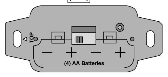
14 GreenSmart2 Troubleshooting 4. Battery Holder Diagram E PRG Button ON REMOTE OFF 5. Transmitter Diagram F A = Power B = Thermostat C = Mode 12


15 Programming Remote Diagram G Gas Pressure Test For Manifold Pressure Test For Incoming Pressure Diagram H 13
 Diagram I 14")
16 GreenSmart2 Basic Wiring (No Remote) Diagram I 14
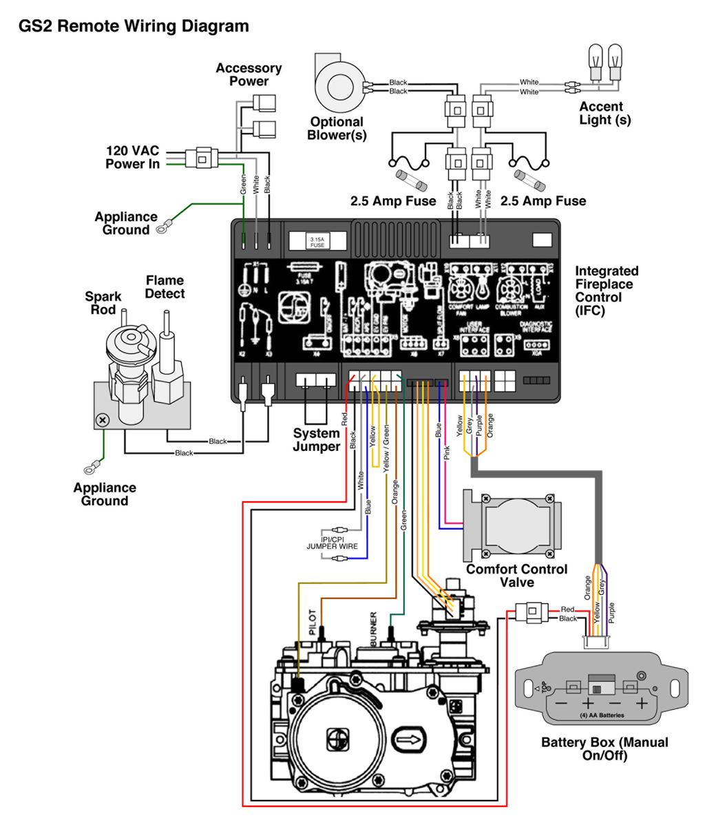
17 GreenSmart2 Remote Wiring Diagram J ON REMOTE OFF 15

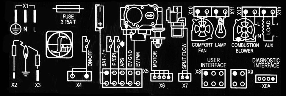
18 GreenSmart2 IFC Guide Diagram K 16
f i r e - p a r t s. c o m
 System Overview: The primary components that are included in the SIT Proflame II GTMFS System Gas Valve Integrated Fireplace Control (IFC) SIT Pilot Assembly Transmitter (remote control) (GTMF model) 2
Troubleshooting Electronic Ignition
 Troubleshooting Electronic Ignition Bob Wise CVC Coaching This session is designed to provide a broad approach to troubleshooting electronic ignition systems. Various hearth electronic systems will be
Troubleshooting Guide
 Troubleshooting Guide IntelliFire Plus Ignition System *For authorized gas technicians use only. 9/15/2011 Hearth & Home Technologies Page1 Guide Table of Contents Introduction. 3 Tools and Instruments...
American Flame AF-4000 Series Intermittent Pilot Ignition System Trouble Shooting Guide
 American Flame AF-4000 Series Intermittent Pilot Ignition System Trouble Shooting Guide Contents IPI System Overview Pgs. 2-5 Module Audible Alerts Pgs. 6-7 Module Error Codes Pgs. 8-9 Extension Module
SAVANNAH EI & DELUXE SYSTEM TROUBLE SHOOTING GUIDE
 SAVANNAH EI & DELUXE SYSTEM TROUBLE SHOOTING GUIDE ***PLEASE MAKE SURE TO LEARN THE REMOTE TO THE SYSTEM (REFER TO PG 6) AND CHECK THE BATTERIES FIRST!!! (American Flame AF-4000 Series) Intermittent Pilot
Troubleshooting Manual
 Troubleshooting Manual NOTICE: DO NOT DISCARD THIS MANUAL Models: LEGACY42-IFT PHOENIX42-IFT 1 TABLE OF CONTENTS A. Normal Operation...3 B. Wiring Diagram...4 C. Troubleshooting IntelliFire Touch...5 D.
CAUTION WARNING WARNING PROFLAME 2 UPGRADE KIT RX RX 300 NG/LP. Installation & Maintenance Manual
 & Maintenance Manual PROFLAME 2 UPGRADE KIT + RX 300 NG/LP Upgrade Kit NG/LP Proflame 2 (Basic to Full Load with Remote) THIS KIT IS FOR USE WITH THE FOLLOWING MODELS: RX200: B34DT-2-F : B34 TOP VENT,
Circuit Board Diagnostics
 Circuit Board Diagnostics NOTE: Discharge your body s static electricity before touching unit. An electrostatic discharge can adversely affect electrical components. Troubleshoot Integrated Control Module
TECHNICAL SERVICE DEPARTMENT Technical Service Bulletin LowNOx Commercial Gas Electronic Spark Ignition Sequence
 The Universal TM gas LowNOx series water heaters contain an electronic spark ignition system. The heater is connected to a 120VAC power source required by the transformer. The transformer steps down the
Troubleshooting Guide
 Troubleshooting Guide *For Authorized Gas Technicians Use Only* 1 Table of Contents Introduction 3 Tools and Instruments 4 Intellifire Component Parts 5 Intellifire Basics 7 Problem: The Ignitor makes
POOL PILOT SOFT TOUCH OPERATING, TROUBLESHOOTING AND TECHNICAL CHEAT SHEET
 POOL PILOT SOFT TOUCH OPERATING, TROUBLESHOOTING AND TECHNICAL CHEAT SHEET NORMAL OPERATING MODE OF SOFT TOUCH 1. Output Lights will pulsate to indicate Chlorine production. a. There are 7 lights to indicate
Troubleshooting Guide
 Troubleshooting Guide This guide contains information for identifying and correcting issues that may arise. Applicable Models: i200 i200p i250 i250p i200x i201x i250x i251x iq251 iq251d iq751 iq1001 iq1501
1080 CF Valve Replacement Instructions
 Overview This kit includes the newer American Flame gas control valve designed specifically for the 1080 CF gas fireplace. If you have a 1080 CF fireplace, and you are uncertain as to whether this kit
Note: An arrow ( ) found in the text signifies change in content.
 found in the text signifies change in content.") Installation Instructions LPK-OH - LEGACY/PHOENIX NG to LP Gas Conversion Kit Models: LEGACY42-IFT PHOENIX42-IFT WARNING: This conversion kit shall be installed by a qualified service agency in accordance
Installation Instructions LPK-OH - LEGACY/PHOENIX NG to LP Gas Conversion Kit Models: LEGACY42-IFT PHOENIX42-IFT WARNING: This conversion kit shall be installed by a qualified service agency in accordance
SERVICE MANUAL (INTERNATIONAL)
") SERVICE MANUAL (INTERNATIONAL) IMPINGER CONVEYOR OVENS MODEL 1433-000-E, 1434-000-E, 1456, 1457 WITH PUSH BUTTON CONTROLS Lincoln Foodservice Products, LLC 1111 North Hadley Road Fort Wayne, Indiana 46804
SERVICE MANUAL (INTERNATIONAL) IMPINGER CONVEYOR OVENS MODEL 1433-000-E, 1434-000-E, 1456, 1457 WITH PUSH BUTTON CONTROLS Lincoln Foodservice Products, LLC 1111 North Hadley Road Fort Wayne, Indiana 46804
SERVICE MANUAL RRG SERIES HEAVY DUTY GAS GRIDDLE - NOTICE - ML ML ML RRG Shown
 SERVICE MANUAL RRG SERIES HEAVY DUTY GAS GRIDDLE 24RRG 36RRG 48RRG 60RRG ML-135339-00024 ML-135340-00036 ML-135341-00048 ML-135342-00060 24RRG Shown - NOTICE - This Manual is prepared for the use of trained
SIT Pilot Assembly Retrofit - # 308 (Replaces R. Shaw Pilot Asbly) (SKU # )
 (SKU # )") Check Condition of Shipment SIT Assembly Retrofit - # 308 Upon receipt of this kit, check the condition of the packaging. Damage to the package should be noted on the carrier's freight receipt. Any damage
Check Condition of Shipment SIT Assembly Retrofit - # 308 Upon receipt of this kit, check the condition of the packaging. Damage to the package should be noted on the carrier's freight receipt. Any damage
Fan, DVI Insert 31 and 33 DVI Installation Instructions (sku )
") Packing List Fan, DVI Insert 31 and 33 DVI Left and Right Blower Assembly (with grommets and bushings) (2) Blower Mounting Nuts Wiring Harness Rheostat Snap Disc Rheostat Nut and Knob Nylon Rheostat Spacer
Packing List Fan, DVI Insert 31 and 33 DVI Left and Right Blower Assembly (with grommets and bushings) (2) Blower Mounting Nuts Wiring Harness Rheostat Snap Disc Rheostat Nut and Knob Nylon Rheostat Spacer
564 Shadowbox Face (w Screen) Instructions
 Instructions") Packing List Compatibility Face Bottom Shield (2) Face Brackets (8) Screws (#8 x 3/8 Phillips) (5) Screws (#8 x 5/8 hex head) Drill Template 11/64 Drill Bit Items Used with Optional Switch Box (see note
Packing List Compatibility Face Bottom Shield (2) Face Brackets (8) Screws (#8 x 3/8 Phillips) (5) Screws (#8 x 5/8 hex head) Drill Template 11/64 Drill Bit Items Used with Optional Switch Box (see note
AUTOMATIC REMOTE CAPABLE SAFETY PILOT SYSTEM
 OWNER S MANUAL AUTOMATIC REMOTE CAPABLE SAFETY PILOT SYSTEM PRE-ASSEMBLED READY FOR INSTALLATION FEATURES: NON-STANDING FLAME-SENSING PILOT MANUAL SWITCH ON/OFF OPTIONAL REMOTE CONTROL BATTERY OPERATION
MICRO P-711 Exerciser Instruction Book
 DINOSAUR ELECTRICS MICRO P-711 Exerciser Instruction Book First Edition Table of Contents Introduction 1- MICRO P-711 tests AC DC Gas 5 Dometic eyebrow ID drawings 6 Dometic AES and AMES tests AC 7 DC
MODEL RVS304. REMOTE CONTROLLED SAFETY PILOT KIT Supplemental Installation Instructions for use with Natural Gas Log Sets
 MODEL RVS304 REMOTE CONTROLLED SAFETY PILOT KIT Supplemental Installation Instructions for use with Natural Gas Log Sets NOTE: This kit is for both Natural Gas and LP Gas applications. For LP (Propane)
BG1600M Intermittent Pilot Ignition Control
 Installation Instructions Issue Date March, 00 BG600M Intermittent Pilot Ignition Control Application The BG600M Intermittent Pilot Ignition Control is a safety control designed for indirect burner ignition
Innovations in Remote Controls
 Innovations in Remote Controls Terry Brumbaugh SkyTech Products Group This session will cover various types of remote controls that are used in the hearth industry. From ultra-sonic remotes to infrared
Solstice and Solstice Supreme High Efficiency Gas Fryers SG/SSH Series Service Manual
 Solstice and Solstice Supreme High Efficiency Gas Fryers SG/SSH Series Service Manual Notice In the event of problems or questions about your order, contact the Pitco Frialator factory at (603) 225-6684.
SERVICE MANUAL (DOMESTIC)
") SERVICE MANUAL (DOMESTIC) IMPINGER CONVEYOR OVENS IMPINGER II - ADVANTAGE SERIES Lincoln Foodservice Products, LLC 1111 North Hadley Road Fort Wayne, Indiana 46804 United States of America Phone : (800)
SERVICE MANUAL (DOMESTIC) IMPINGER CONVEYOR OVENS IMPINGER II - ADVANTAGE SERIES Lincoln Foodservice Products, LLC 1111 North Hadley Road Fort Wayne, Indiana 46804 United States of America Phone : (800)
DEXEN INDUSTRIES Inc. GENERAL CATALOG. DEXEN INDUSTRIES Inc.
 DEXEN INDUSTRIES Inc. GENERAL CATALOG DEXEN INDUSTRIES Inc. 6003 GAS VALVES 6003-series gas valve is an effective and reliable gas valve for low-btu gas product and application. The product is most commonly
INSTALLATION INSTRUCTIONS FOR PCDE-36VA CONVERSION KIT
 INSTALLATION INSTRUCTIONS FOR PCDE-36VA CONVERSION KIT CONVERTING FROM NATURAL GAS TO PROPANE/LP GAS For Use When Converting Model (V)V36ENA Series This conversion kit must be installed by a qualified
GAS CONVERSION KIT INSTALLATION INSTRUCTIONS
 GAS CONVERSION KIT INSTALLATION INSTRUCTIONS These instructions apply to the following gas conversion kits: 8261139 8261140 8261141 8261142 8261143 8261144 8261158 8261747 8261748 8261964 8261965 8263059
PAGE 1. TES Operation & Testing Guidelines: Tes Trouble shooting
 PAGE 1 This document outlines questions to ask and components to check during TES troubleshooting. More detailed troubleshooting procedures are available in the TES Troubleshooting Guide. 1. Flow Light
(For serial numbers before w/ analog control)
") SEQUENCE OF OPERATIONS (For serial numbers before 2038616 w/ analog control) MODEL 1154-000-EA NAT. GAS 230 VAC 50 HZ. 1 PHASE MODEL 1155-000-EA LP GAS 230 VAC 50 HZ. 1 PHASE POWER SUPPLY Electrical power
SEQUENCE OF OPERATIONS (For serial numbers before 2038616 w/ analog control) MODEL 1154-000-EA NAT. GAS 230 VAC 50 HZ. 1 PHASE MODEL 1155-000-EA LP GAS 230 VAC 50 HZ. 1 PHASE POWER SUPPLY Electrical power
Solstice Electric Fryers SE Series Service Manual
 Solstice Electric Fryers SE Series Service Manual L22-330 R1 (10/12) Notice In the event of problems or questions about your order, contact the Pitco Frialator factory at (603) 225-6684. In the event of
Spare Parts Information List
 REGENCY Spare Parts Information List Effective 1st September 2010 ALL PRICES EXCLUDE GST AIR GROUP AUSTRALIA 28/30 DIVISION STREET WELSHPOOL WA 6106 Telephone (08) 9350 2200 Facsimile (08) 9353 4225 www.airgroup.com.au
NIDAC EMC Communicating Motor
 NIDAC EMC Communicating Motor IFC 12 V Variable Speed Connection Variable Speed Connection 12 V = + 12 Volt DC RX = Motor to Furnace Control Data TX = Furnace to Motor Control Data GND = 12 Volt DC Ground
Robert H. Peterson Co.
 RHP Robert H. Peterson Co. OWNER S MANUAL AUTOMATIC REMOTE CAPABLE SAFETY PILOT SYSTEM PRE-ASSEMBLED READY FOR INSTALLATION (Suitable for G4, G45, and PB series burners) (Sizes 12"- 24" for natural; 12"-
Section 7 - Troubleshooting Guide
 Section 7 - Troubleshooting Guide Section 7 - Troubleshooting Guide IMPORTANT While this troubleshooting guide provides information to aid in troubleshooting problems with the range, it does not contain
INSTALLATION DATA 712 Series Pilot
 INSTALLATION DATA 712 Series Pilot Ignition Systems (FLAME RECTIFICATION) LOCKOUT MODEL 712-005 712-006 712-008 712-009 NON-LOCKOUT MODELS 712-005 712-016 712-017 712-019 712-022 CSA DESIGN CERTIFIED TO
SERVICE MANUAL. Thermador Pro Harmony Range. Model: PRL364GDH/01
 SERVICE MANUAL Thermador Pro Harmony Range Model: PRL364GDH/01 TABLE OF CONTENTS 1 General... 4 1.1 Technical Documents to Read Prior to Servicing... 4 1.2 Wiring Diagram... 4 1.3 Data Rating Plate...
PARTS AND SERVICE MANUAL
 PARTS AND SERVICE MANUAL FOR THE 23 INSERT FIREPLACE MODEL NUMBER: DFI2309 TABLE OF CONTENTS OPERATION PAGE 1 PARTS DRAWING PAGE 3 PARTS LIST PAGE 4 WIRING DIAGRAM PAGE 5 LIGHT BULB REPLACEMENT PAGE 6
Auto-Level Troubleshooting (Old Platform) Electronic Control- Prior to 2009, Pressure Switch Control panel #s 2057, 2058, 2795, 2795B
 Electronic Control- Prior to 2009, Pressure Switch Control panel #s 2057, 2058, 2795, 2795B") Auto-Level Troubleshooting (Old Platform) Electronic Control- Prior to 2009, Pressure Switch Control panel #s 2057, 2058, 2795, 2795B This guide addresses the troubleshooting of electronic controls used
Auto-Level Troubleshooting (Old Platform) Electronic Control- Prior to 2009, Pressure Switch Control panel #s 2057, 2058, 2795, 2795B This guide addresses the troubleshooting of electronic controls used
INSTALLATION INSTRUCTIONS
 INSTALLATION INSTRUCTIONS PROPANE GAS CONVERSION KIT Standard Altitude Only / 0 2000 FT (0 610m) Small Package Products / 40,000 130,000 Btu/hr NPLPCONV013C00 This kit is used on: Two Stage Models: PGR5
Heater Troubleshooting Guides
 Heater Troubleshooting Guides Table Of Contents LRZE, 3 LRZM.. 4, 5 LXi.. 6, 7 LITE LD.. 8, 9 LITE LJ.. 10, 11 LITE LG. 1, 13 LX or LT STANDARD BURNERS 14, 15 LX or LT LOW x BURNERS. 16, 17 HiE 18, 19
AUTOMATIC REMOTE CAPABLE SAFETY PILOT SYSTEM
 OWNER S MANUAL AUTOMATIC REMOTE CAPABLE SAFETY PILOT SYSTEM PRE-ASSEMBLED READY FOR INSTALLATION (Suitable for G4, G45, and PB series burners) (Sizes 12"- 24" for natural; 12"- 36" for propane gas) MODEL
DIAGNOSTIC TROUBLESHOOTING INDEX
 DIAGNOSTIC TROUBLESHOOTING INDEX Curtis Industries, LLC. 111 Higgins Street Worcester, MA 01606 Telephone: (508) 853-2200 Fax: (800) 876-9104 www.snoproplows.com TROUBLESHOOTING INDEX - BY PROBLEM Section
Service Manual Mozart Fireplace
 Service Manual Mozart Fireplace Model Numbers: CFP3913 REV PCN DATE 00 11637 Sep 23, 09 Dimplex North America Limited 1367 Industrial Road Cambridge ON Canada N1R 7G8 1-888-346-7539 www.dimplex.com In
! WARNING To avoid risk of electrical shock, personal injury or death; disconnect power to oven before servicing, unless testing requires power.
 Technical Information Gas Slide-In Range JGS8750ADB/S/W JGS8850ADB/Q/S/W Due to possibility of personal injury or property damage, always contact an authorized technician for servicing or repair of this
Troubleshooting Guide: Elevance Delivery Systems
 Troubleshooting Guide: Elevance Delivery Systems FOR USE BY MIDMARK TRAINED TECHNICIANS Contents Description / Links Troubleshooting Charts ICM Screens Assistant s Unit Instruments (Elevance & European)
BURNER SERVICE MANUAL 37
 BURNER SERVICE MANUAL 37 BURNER ASSEMBLY #7-00024 #7-00033 #7-00034 #7-00035 19 1 7-0005 Motor 1/5 HP 3450 RPM Cap. 115V/230V 1 7-20554 Motor, 1/5 HP 3450 RPM 115V (7-00024) 1 2 7-21854001 Fan, Burner
G72x Series Direct Spark Ignition Controls
 Installation Sheets Manual 121 Gas Combustion Combination Controls and Systems Section G Technical Bulletin G72x Issue Date 1299 G72x Series Direct Spark Ignition Controls Figure 1: G72x Direct Spark Ignition
TO BE USED ONLY BY AUTHORISED PERSONNEL
 SERVICE MANUAL for BOSTON (MG 3000 STD) SANTA FE (CALGARY, MG 3000 FLS) & ODESSA (PG 3000) GAS FIRES TO BE USED ONLY BY AUTHORISED PERSONNEL PART No 588402 Issue E Nov. 2001 CONTENTS TROUBLESHOOTING Page
SERVICE INSTRUCTIONS KEATING keatingofchicago.com
 SERVICE INSTRUCTIONS 1-800-KEATING keatingofchicago.com FIELD REPLACEMENT KIT - for replacing Flame Switch 037406 and Hardware with Spark Ignition Module For use on all 14" rear drain and all larger size
Ebling Back Blade Snow Plow Wireless Controller Kit Only sold by SnowplowsPlus.com and ControlAllWireless.com
 Ebling Back Blade Snow Plow Wireless Controller Kit Only sold by SnowplowsPlus.com and ControlAllWireless.com WARNING Always unplug the plow or shut off the battery breaker when in transport or not in
XR8 SERIES. Effective june 12, 2015
 XR8 SERIES gas & ELECTRIC ROTATING RACK convection ovens REPLACEMENT PARTS LIST Effective june 2, 20 Superseding All Previous Parts Lists. The Company reserves the right to make substitution in the event
DVL Cypress Face Installation Instructions (SKU )
") Table of Contents Compatibility... 1 Packing List... 1 Installation... 2 Prepare the Insert for Face Installation... 2 Assemble the Face... 6 Attach the Surround Panels (if applicable) and Face... 10 Hang
Table of Contents Compatibility... 1 Packing List... 1 Installation... 2 Prepare the Insert for Face Installation... 2 Assemble the Face... 6 Attach the Surround Panels (if applicable) and Face... 10 Hang
Turn Signal / Horn Kit PN 7101 by All years Polaris RZR 1000 and RZR 900, 900-4, 900 trail, 900S and 900XC STOP - THIS KIT IS DESIGNED
 All years Polaris RZR 1000 and 1000-4 2015 RZR 900, 900-4, 900 trail, 900S and 900XC STOP - THIS KIT IS DESIGNED SPECIFICALLY FOR ALL YEAR AND MODEL POLARIS RZR 1000 AND 1000-4. ALSO THE 2015 POLARIS RZR
SERVICE MANUAL (INTERNATIONAL)
") SERVICE MANUAL (INTERNATIONAL) IMPINGER CONVEYOR OVEN MODEL 1100-000-A SERIES (SN 2038615 & BELOW) SERVICE MANUAL Lincoln Foodservice Products, LLC 1111 North Hadley Road Fort Wayne, Indiana 46804 United
SERVICE MANUAL (INTERNATIONAL) IMPINGER CONVEYOR OVEN MODEL 1100-000-A SERIES (SN 2038615 & BELOW) SERVICE MANUAL Lincoln Foodservice Products, LLC 1111 North Hadley Road Fort Wayne, Indiana 46804 United
Reproduction or other use of this Manual, without the express written consent of Vulcan, is prohibited.
 SERVICE MANUAL GAS BRAISING PANS (30 & 40 GALLON) VG30 VG40 ML-126847 ML-126848 VG40 SHOWN - NOTICE - This Manual is prepared for the use of trained Vulcan Service Technicians and should not be used by
BGH2UNCNTRLHT-01 Universal Hot Surface Ignition Control
 Installation Instructions BGH Issue Date vember 9, 2017 BGH2UNCNTRLHT-01 Universal Hot Surface Ignition Control Application The BASO Gas Products BGH2UNCNTRLHT-01 Universal Series Hot Surface Ignition
SERVICE INSTRUCTIONS KEATING keatingofchicago.com
 SERVICE INSTRUCTIONS 1-800-KEATING keatingofchicago.com FIELD REPLACEMENT KIT - for replacing Flame Switch 037406 with External Spark Module Box Assembly For use on all 10x11 fryers, 14" Front Drain fryers
INSTALLATION INSTRUCTIONS
 INSTALLATION INSTRUCTIONS PROPANE GAS CONVERSION KIT High Altitude Only / 2001 6000 FT (610 1829m) Small Package Products / 40,000 130,000 Btu/hr NPLPCONV014C00 This kit is used on: Two Models: PGR5 (Two
X4 Installation and Operation Manual - POWER FLAME INCORPORATED
 7.13.2 Set the burner s combustion air inlet damper to the approximate setting as shown in this manual for the desired firing rate. Also, verify that the correct main orifice is installed in the main orifice
MODERUSTIC Battery Operated Remote Control Electronic Safety Pilot System IPI Intermittent Pilot Light For Fire Pits or Fireplaces
 MODERUSTIC Battery Operated Remote Control Electronic Safety Pilot System IPI Intermittent Pilot Light For Fire Pits or Fireplaces Model: AFVK-SP-MH/L Remote flame height adjustment DC Motor Drive Hi,
Service Manual. Model Number: DF2426GB DF2426SS DF2550 DF2562. UL Part Number to 500
 Service Manual Model Number: DF2426GB DF2426SS DF2550 DF2562 UL Part Number 6905050100 to 500 IMPORTANT SAFETY INFORMATION: Always read this manual first before attempting to service this fireplace. For
AHE S - 12 VDC AHE X - 12 VDC AHE X - 12 VDC
 Shop Manual Model Numbers AHE-100-04S - 12 VDC AHE-120-04X - 12 VDC AHE-130-04X - 12 VDC TABLE OF CONTENTS Section 1 Section 2 Section 3 Section 4 General Heater Information 1.1 Component Overview 1.2
XR8 SERIES GAS & ELECTRIC ROTATING RACK CONVECTION OVENS REPLACEMENT PARTS LIST
 XR SERIES GAS & ELECTRIC ROTATING RACK CONVECTION OVENS REPLACEMENT PARTS LIST EFFECTIVE JUNE, 202 Superseding All Previous Parts Lists. The Company reserves the right to make substitution in the event
AUTOMATIC REMOTE LIGHTING SAFETY PILOT SYSTEM FOR NATURAL OR PROPANE GAS EPK-1 PILOT KITS
 INSTALLATION & OWNER S MANUAL AUTOMATIC REMOTE LIGHTING SAFETY PILOT SYSTEM FOR NATURAL OR PROPANE GAS Models: EPK-1(M)(P) FEATURES: INTERMITTENT PILOT IGNITION NON-STANDING FLAME-SENSING PILOT MANUAL
G76x Direct Spark Ignition Controls
 Installation Sheets Manual 121 Gas Combustion Combination Controls and Systems Section G Technical Bulletin G76x Issue Date 0400 G76x Direct Spark Ignition Controls Figure 1: G76x Direct Spark Ignition
THIS GUIDE IS INTENDED FOR DEALERS AND SOLAR COMFORT TECHNICIANS ONLY AND IS NOT MEANT OR INTENDED TO BE REPRODUCED OR DISTRIBUTED TO THE CONSUMER
 THIS GUIDE IS INTENDED FOR DEALERS AND SOLAR COMFORT TECHNICIANS ONLY AND IS NOT MEANT OR INTENDED TO BE REPRODUCED OR DISTRIBUTED TO THE CONSUMER Table of Contents Page Tools Needed (A) 3 Replacement
Installation Instructions for. For Use When Converting Model (V)M42(B) Vented Decorative Fireplace. Fold Bi-Fold Door After Releasing
M42(B) Vented Decorative Fireplace. Fold Bi-Fold Door After Releasing") Installation Instructions for PCBM-42 conversion kit Converting from Natural Gas to Propane/LP Gas For Use When Converting Model (V)M42(B) Vented Decorative Fireplace This conversion kit must be installed
Installation Instructions for PCBM-42 conversion kit Converting from Natural Gas to Propane/LP Gas For Use When Converting Model (V)M42(B) Vented Decorative Fireplace This conversion kit must be installed
CAUTION. Even Brakes with a black cable need second vehicle kit Even Brakes with a blue cable need second vehicle kit 98450
 cable not included cable not included Even Brakes with a blue cable need second vehicle kit 98450 Even Brakes with a black cable need second vehicle kit 98400 Check the Even Brake serial number before
Table of Contents. Timer Identification Timer ID BLU-U Features: 1K 6K BLU-U Features 1K 6K
 DUSA Pharmaceuticals, Inc. Table of Contents Go to Chart # Timer Identification Timer ID BLU-U Features: 1K 6K BLU-U Features 1K 6K BLU-U Features: 10K BLU-U Features 10K BLU-U Symptom Fans Running, Timer
TABLE OF CONTENTS. 1 General Operation and Controls... 10
 TABLE OF CONTENTS 1 General... 5 1.1 Technical Documents to Read Prior to Servicing... 5 1.2 Data Rating Plate... 5 1.3 Wiring Diagram... 6 1.4 Recommended Tools and Supplies... 6 1.5 Important Safety
POCKET GUIDE for TROUBLESHOOTING Gas Products To be used by F.P.I. trained service technicians only.
 POCKET GUIDE for TROUBLESHOOTING Gas Products To be used by F.P.I. trained service technicians only. 908-489 02/26/99 Table of Contents Tools and Instruments...3 Problem A Pilot not igniting after repeated
SECOND GENERATION Use this guide with unit serial number prefix beginning with BWF using Terra Power separator.
 Technical Information and Diagnostic Guide for SECOND GENERATION Use this guide with unit serial number prefix beginning with BWF using Terra Power separator. This guide will assist you in becoming more
ROBERT H. PETERSON CO. AUTOMATIC REMOTE LIGHTING SAFETY PILOT SYSTEM WITH VARIABLE FLAME-HEIGHT REMOTE FOR NATURAL OR PROPANE GAS. Model APK-17(M)(P)
(P)") ROBERT H. PETERSON CO. Owner s Manual AUTOMATIC REMOTE LIGHTING SAFETY PILOT SYSTEM WITH VARIABLE FLAME-HEIGHT REMOTE FOR NATURAL OR PROPANE GAS FEATURES: CONTROL OPERATED ON/OFF VARIABLE FLAME-HEIGHT
ROBERT H. PETERSON CO. Owner s Manual AUTOMATIC REMOTE LIGHTING SAFETY PILOT SYSTEM WITH VARIABLE FLAME-HEIGHT REMOTE FOR NATURAL OR PROPANE GAS FEATURES: CONTROL OPERATED ON/OFF VARIABLE FLAME-HEIGHT
CAUTION All safety information must be followed as provided in Service Manual
 Double Oven Gas Range Technical Information MGR6875AD* Due to possibility of personal injury or property damage, always contact an authorized technician for servicing or repair of this unit. Refer to Service
Models: AFVK-SP-SPLIT AFVK-SP-H/L-SPLIT AFVK-SP-MH/L-SPLIT INSTALLATION AND OPERATING INSTRUCTION
 Electronic Safety Pilot System for Vented Gas Logs Models: AFVK-SP-SPLIT AFVK-SP-H/L-SPLIT AFVK-SP-MH/L-SPLIT IF YOU CANNOT READ OR UNDERSTAND THESE INSTALLATION INSTRUCTIONS DO NOT ATTEMPT TO INSTALL
INSTALLATION INSTRUCTIONS
 INSTALLATION INSTRUCTIONS PROPANE GAS CONVERSION KIT High Altitude Only / 2001 6000 FT (610 1829m) Small Package Products / 40,000 130,000 Btu/hr NPLPCONV014B00 This kit is used on: Two Stage Models: PGR5
SERVICE MANUAL. Thermador Pro Harmony Range. Model: PRL304GH/10-17
 SERVICE MANUAL Thermador Pro Harmony Range Model: PRL304GH/10-17 TABLE OF CONTENTS 1 General... 4 1.1 Technical Documents to Read Prior to Servicing... 4 1.2 Wiring Diagram... 4 1.3 Data Rating Plate...
Reproduction. Not for ADVANCE PRODUCT SERVICE INFORMATION INFORMATION BULLETIN NO: 36 DATE: 11/27/02 SUBJECT: POWERLINK SYSTEM
 ADVANCE PRODUCT SERVICE INFORMATION INFORMATION BULLETIN NO: 36 DATE: 11/27/02 SUBJECT: POWERLINK SYSTEM FILE IN: INTEK & VANGUARD REPAIR MANUAL GFCI Inverter Stator POWERLINK Harness Reset ON OFF Switch
ILQ TROUBLESHOOTING GUIDE
 TROUBLESHOOTING GUIDE Rev. 1.1, Date 1-15-2009 1 Series (until June 2008) Troubleshooting: with rectangle circuit board on driver side Table of content: Page 1) Gate overview and connector setup...2 2)
PROFIRE 1100i IGNITION FLAME SAFETY CONTROLLER
 PROFIRE 1100i IGNITION FLAME SAFETY CONTROLLER Cautions WARNING: EXPLOSION HAZARD- -DO NOT SERVICE UNLESS AREA IS KNOWN TO BE NON- HAZARDOUS -DO NOT OPEN WHEN ENERGIZED EXPLOSION HAZARD- -SUBSTITUTION
CATALOG OF REPLACEMENT PARTS
 CATALOG OF REPLACEMENT PARTS MINI RACK OVEN OV310G ML-132515 A product of BAXTER MFG. CO., INC. 19220 STATE ROUTE 162 EAST, ORTING, WA 98360 FORM 43242 (October 2011) Table of Contents 3 ADVANCED CONTROL
ALTERNATOR PRECAUTIONS. Some precautions should be taken when working on this, or any other, AC charging system.
 The alternator charging system is a negative (-) ground system which consists of an alternator, a regulator, a charge indicator, a storage battery and wiring connecting the components, and fuse link wire.
Grout Pump Automatic & Manual Troubleshooting Gas Wiring Diagram
 Grout Pump Automatic & Manual Troubleshooting 40-500 Gas Wiring Diagram Turn engine off and relieve hydraulic pressure and grout pressure before troubleshooting. Note: Typically there is a wiring diagram
DVM36/42 SERIES LOG SET/BURNER MODULES INSTALLATION INSTRUCTIONS
 DVM36/42 SERIES LOG SET/BURNER MODULES INSTALLATION INSTRUCTIONS For Use With (V)TC36 Series, (V)VC36/42 Series, (V)KC36/42 Series or DVC Series Fireplaces This log set/burner module must be installed
This Manual is prepared for the use of trained Vulcan Service Technicians and should not be used by those not properly qualified.
 SERVICE MANUAL GRA SERIES GAS FRYERS WITH KLEENSCREEN PLUS FILTRATION SYSTEMS 2GR45AF KLEENSCREEN FRYER BATTERY MODEL ML MODEL ML 1GR45A 136647 3GR85AF 136655 1GR65A 136648 4GR45AF 136656 1GR85A 136649
1984 Jeep CJ7. IGNITION SYSTEM - SOLID STATE' 'Distributors & Ignition Systems MOTORCRAFT SOLID STATE IGNITION (SSI)
") TESTING SECONDARY CIRCUIT CHECK CAUTION: When checking secondary voltage, do not remove spark plug wires from spark plugs No. 3 on 4-cylinder, No. 1 or 5 on 6-cylinder and No. 3 or 4 on V8 Engines. 1.
TESTING SECONDARY CIRCUIT CHECK CAUTION: When checking secondary voltage, do not remove spark plug wires from spark plugs No. 3 on 4-cylinder, No. 1 or 5 on 6-cylinder and No. 3 or 4 on V8 Engines. 1.
burners with or without fan. It conforms to EN C). APPROVAL EU type test approval as per EU Gas Appliance Directive.
. APPROVAL EU type test approval as per EU Gas Appliance Directive.") LAST UPDATE 29/08/12 INSTALLATION INSTRUCTIONS v. 3 UNIT SPECIFICATIONS Main Gas Valve, Pilot Gas Valve Ionisation, Ignition and Flame Monitoring with Common Electrode or Remote Sensor Integrated Cyclic
LAST UPDATE 29/08/12 INSTALLATION INSTRUCTIONS v. 3 UNIT SPECIFICATIONS Main Gas Valve, Pilot Gas Valve Ionisation, Ignition and Flame Monitoring with Common Electrode or Remote Sensor Integrated Cyclic
G600 Series Replacement Intermittent Pilot Ignition Controls
 Installation Instructions G600 Issue Date 0601 G600 Series ment Intermittent Pilot Ignition Controls Installation IMPORTANT: These instructions are intended as a guide for qualified personnel installing
Service Manual. Contents. Names of components. 3. Specifications Wiring Diagam Sequence Time Chart
 Service Manual Contents 1. Names of components 2 2. Safety Devices 3 3. Specifications 4 4. Wiring Diagam 4 5. Sequence Time Chart 5 6. 7. 8. Troubleshooting 6 Standard resistance & Voltage 13 Check &
INSTALLATION INSTRUCTIONS NATURAL TO PROPANE CONVERSION KIT
 INSTALLATION INSTRUCTIONS NATURAL TO PROPANE CONVERSION KIT NAHA0080LP or PART NO. 83388 NOTE: Read the entire instruction manual before starting the installation. SAFETY CONSIDERATIONS Installing and
INSTALLER MANUAL USER MANUAL. Contents
 Installation & user manual two way Contents INSTALLER MANUAL Important information General 1. Technical data 2. Description Installation: 1. Positioning the unit 2. Connection. 3. Parts description. 4.
Installation instructions for KIT15017, KIT15018, KIT15019, and KIT15020
 18-CH41D1-1 Installation instructions for KIT15017, KIT15018, KIT15019, and KIT15020 WARNING: HAZARDOUS VOLTAGE - DISCONNECT POWER BEFORE SERVICING ALL phases of this installation must comply with NATIONAL,
INSTALLATION INSTRUCTIONS FOR PCBM-36C CONVERSION KIT From Natural Gas to Propane/LP Gas
 INSTALLATION INSTRUCTIONS FOR PCBM-36C CONVERSION KIT From Natural Gas to Propane/LP Gas For Use When Converting Models CB36N and VCB36N This conversion kit must be installed by a qualified service agency.
Wolverine Turn Signal / Horn Kit 2102
 All years Yamaha Wolverine STOP - THIS KIT IS DESIGNED SPECIFICALLY FOR ALL YEAR AND MODELS YAMAHA WOLVERINE. IF YOUR MACHINE IS NOT ONE OF THESE MODELS DO NOT PROCEED. Contact Ryco Motorsports or your
Crest Heating Boilers FBN(L)
") Replacement Parts List PARTS & SERVICE DEPARTMENT Nashville, Tennessee 877-554-5544 Fax: 615-882-2918 parts_team@lochinvar.com www.lochinvar.com Crest Heating Boilers FBN(L) 751-2001 59 IMG01113 52 65
Replacement Parts List PARTS & SERVICE DEPARTMENT Nashville, Tennessee 877-554-5544 Fax: 615-882-2918 parts_team@lochinvar.com www.lochinvar.com Crest Heating Boilers FBN(L) 751-2001 59 IMG01113 52 65
GENERAL <ELECTRICAL>
 00E-1 GROUP 00E GENERAL CONTENTS HARNESS CONNECTOR INSPECTION................................. 00E-2............. 00E-6................. 00E-6 TROUBLESHOOTING STEPS.......... 00E-6 INFORMATION
G821L/G822L Series Integrated Function Direct Spark Ignition Controls
 Installation Sheets Manual 121 Gas Combustion Combination Controls and Systems Section G Technical Bulletin G821L/G822L Issue Date 1199 G821L/G822L Series Integrated Function Direct Spark Ignition Controls
27" GAS DRYER MODELS: WGD94HEAW2 (White) WGD94HEAC2 (Chrome Shadow) 06/25/ Whirlpool Corporation Part No. W Rev.
 WGD94HEAC2 (Chrome Shadow) 06/25/ Whirlpool Corporation Part No. W Rev.") 27" GAS DRYER MODELS: WGD94HEAW2 (White) WGD94HEAC2 (Chrome Shadow) 06/25/2013 2013 Whirlpool Corporation Part W10623349 Rev. A TOP AND CONSOLE PARTS 06/25/2013 2 Part W10623349 Rev. A TOP AND CONSOLE
27" GAS DRYER MODELS: WGD94HEAW2 (White) WGD94HEAC2 (Chrome Shadow) 06/25/2013 2013 Whirlpool Corporation Part W10623349 Rev. A TOP AND CONSOLE PARTS 06/25/2013 2 Part W10623349 Rev. A TOP AND CONSOLE