GIANTMACH UTV & ATV 700/500 SNOW PLOW AND WINCH MANUAL
|
|
|
- Miranda Harvey
- 6 years ago
- Views:
Transcription


1 GIANTMACH UTV & ATV 700/500 SNOW PLOW AND WINCH MANUAL


2 TDJ-A2000 ELECTRIC WINCH INSTRUCTION MANUAL Page 1
3 OPRERATIONAL PRINCIPLE TDJ-A2000 electric winch is made up of 7 major parts # s. The power decreases speed by multistage planetary gearing and this drives the drum (part#4), which in turn rotates and retracts the cable pulling your vehicle free from the obstacle. Pulling out or retracting the cable is done by the transmitting axis moving. WIRING Be sure you are using a 12V automotive battery that is no less than 14AH and the wiring gauge is not less than 8mm 2.Always connect red to (positive) and black to the frame, ensuring a good ground connection when using battery power. MOUNTING REQUIREMENT 1 Select a mounting site on the bumper or frame of your vehicle. Be sure the location you select can withstand the force of the winch pulling heavy objects. Align the winch in the desired location, and mark 4 holes to drill for base of the winch. Then drill these 4 holes on your vehicle. 2 Using steel bolts M , install your winch to the location. Page 2
4 Electrical diagram of the winch: Page 3
5 Page 4

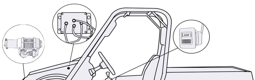
6 Diagram of the Winch Relay 1 Install the Winch Relay to the wall under the hood of the UTV (See diagram above). For the ATV the Winch Relay is to be installed in the box at the rear fender. 2 Properly connect the wires as shown in the diagram to the left or above. 3 Install the control switch connector underneath the dashboard of the UTV or on the handlebars of the ATV. OPERATING THE WINCH 1 To pull out the cable, turn the shifting gear handle (part#6) clockwise to free spool arrow loosen it. Pull out the desired cable length and secure to object. (Always leave at least 4 turns of cable on the spool to prevent pulling the cable out of the winch.) 2 Turn the shifting gear handle (part#6) counterclockwise so that it lines up with the engage arrow. If you hear the click, the working gear is engaged. If you didn t hear the click, turn the handle clockwise slowly or turn Page 5
7 the drum slowly (part#4) until you hear it, then adjust then handle to line up with the engage arrow. If engaged properly, the drum can t rotate while pulling the cable. 3 Put your vehicle in neutral (never leave your vehicle in gear or in park when operating winch) and release your emergency brake so that you are only applying the manual brakes. 4 Connect the power cable, and winch the item as desired. WARNING 1 Never use your winch on a low battery or long enough to run your battery down. 2 Keep your vehicle s engines running to continually recharge the battery. 3 Keep hands, clothing, hair, and jewelry at least 6 inches away from the drum area and cable when operating the winch. 4 If the cable is ever 4.5mm in diameter or less replace it with 4.8-5mm in diameter aircraft wire cable. 5 While operating the winch, do not rotate the gear handle (part#6) located on the rear of electric winch. 6 After retracting the cable, make sure the gear handle (part#6) is turned back into the engage position and the arrows line up. Page 6
8 7 Do not operate the winch for more than 1 and a half minutes at one time. 8 If the electric winch drum does not rotate when engaging it, immediately stop. Do not continue to use if there is no movement because the winch motor may burn out. 9 Not rated for use as a hoist. 10 If operating on a slope the grade should not exceed If operating at a right angle the object height should be less than 2.5 inches of the vehicle wheel radius. 12 Be sure to clean and re-grease the winch regularly. Troubleshooting FAULT REASON SOLUTION The motor doesn t work 1 A poor contact at the terminal;2 Outdoor temperature is below-23, grease freeze, transmitting gear is locked 1 Good contact of the terminal; 2 From 15 TO 23,the machine rotates 1 min without load, recommended operating temperature: -23 to +60 Page 7
9 The motor works but the drum doesn t 1 Shifting gear handle isn t in assigned position; 2 Hexagonal axis can t engage hexagonal 1 Shifting gear handle is just in assigned position; 2 From engage to free spool process, rotate the shifting gear handle or the drum slowly in order for the hexagonal axis to engage hexagonal hole Small pulling force Pulling cable feels ridged Can t pull the cable out Too long operating time, or power shortage of battery Cable wasn t wound neatly when winding Shifting gear handle isn t in assigned position (free spool) Never operate too long, and recharge the battery often Cable should be wound neatly by the introduction of arrangingthread machine correctly. Shifting gear handle is changed to assigned position (free spool) SPECIFICATIONS Rating power Max Pull Max Current 12VDC/ 14AH 8800N(2000 lb) 210A Line Speed 6m/min(When the pull is 3400N) Speed With No Load 10m/min Size (mm) Page 8

10 Snow Plow Assembly diagram Page 9

11 Accessories & Specified items Page 10
12 Serial No. Name Quantity Remarks 1 Guiding plates 2 Contain: nuts*4 (GB/T ) 2 Snow scrapping plate 1 3 Snow plow 1 4 Mounting Arms 1 5 Directional Lever 1 Contain : Rubber sheath 6 Step bolt on lever 1 7 Nut M8 1 GB/T Washer 10 2 GB/T Directional Lever return spring 1 Serial No. Name Quantity Remarks 14 Bolt M GB/T Washer 10 2 GB/T Nut M10 2 GB/T Giant pad φ13 φ Giant padφ13 φ Bolt M GB/T Nut M10 2 GB/T Bolt M GB/T Nut M10 7 GB/T Nut M8 8 GB/T Return spring 1 11 Spring Hook 2 12 Pulley 1 13 Hook protection pipe 1 Contain:Adjusting nut and washer Contain:Pin shaft R Cotter pin 24 U-type Bolt 4 25 Snow plow mounting plate 1 26 Pin shaft 2 self-attached hook 27 Limited Bracket 2 Page 11
 and 7 nuts (#22) 2To install the guiding plates (#1) find the holes on the back lower corners the of snow plow.")
: A: Use the mounting hardware (#17, 18, 19, & 20) to attach the mounting arms (#4) to the snow plow (#3).")
13 Installation Procedure: 1Snow Scraping Plate (#2): to install the snow scrapping plate (#2) properly place it on the bottom of the snow plow (#3). Tighten it with 7 bolts (#21) and 7 nuts (#22) 2To install the guiding plates (#1) find the holes on the back lower corners the of snow plow. Place the guiding plates in the holes with a nut M12 (GB/T ) on each side of the hole. After both are installed, adjust height so they are the same. 3Assemble the mounting arms (#4): A: Use the mounting hardware (#17, 18, 19, & 20) to attach the mounting arms (#4) to the snow plow (#3). Set the mounting arms (#4) on the ground behind the snow plow (#3) and line up the two bottom holes of each. (Picture to the left shows an Page 12
, and pick the hole to use on the mounting arms according the desired angle of the blade. Firmly tighten the bolts in place.")
. Install the spring hooks (#11) in the upper holes on the snow plow (#3).")
14 example). Make sure the bolts are tight and the mounting arms can rotate freely side to side. B:Locate the plow angle adjusting hardware (#14, 15, & 16), and pick the hole to use on the mounting arms according the desired angle of the blade. Firmly tighten the bolts in place. (These can be adjusted as needed to accommodate the desired angle of the snow blade) C:Connect one side of each return spring (#10) to the mounting arms (#4) and the other side to the two spring hooks (#11). Install the spring hooks (#11) in the upper holes on the snow plow (#3). Use the hardware that came with the return springs to attach and adjust the springs to the desired length. (Make sure to use one nut on each side of the hole on the snow plow for extra support.) Page 13
 to hold the lever (#5) and pulley (#12) in place. (Washers should be on the inner side of the pulley).")
15 4 Installing the Directional Lever & Pulley: A: Place the Directional Lever (#5) on the inside of the fixture on the mounting arms (#4) and place the Pulley (#12) on the outer side of the lever and fixture. Use the Directional Lever hardware (#6, 7, & 8) to hold the lever (#5) and pulley (#12) in place. (Washers should be on the inner side of the pulley). Tighten hardware after pulley is in desired angle. B: Place the Return Spring (#10) in between the Directional Lever (#5) and mounting arms (#4). (Place the spring over the bolt on mounting arms to help hold it in place.) After completing the assembly steps above, you should be able to rotate the snow plow to your desired angle; with the lever holding it in that position. Page 14

16 5. (The next steps are easier to do if the vehicle is safely on a lift or a vehicle floor jack). To assemble snow plow mounting plate to the vehicle, first remove the plastic guard underneath the front of your vehicle. Locate the 4 U-type Bolts (#24), the Mounting Plate (#25), and the necessary M8 nuts (#23). Place the U-Type Bolts around the vehicle frame underneath the front of your vehicle and attach the Mounting plate (#25) to them using the provided M8 nuts (#23). 6To install the mounting arms (#4) to the mounting plate (#25) lift the mounting arms(#4) so that the holes on it line up with those on the mounting plate (#25). Place the provided Pin Shafts (#26) through the holes on both the plate (#25) and arms (#4) securing them together safely. Use the self-attached hooks on the pin shafts (#26) to lock the pins in place. Page 15

 and place the winch cable inside of the pulley.")
17 Connecting the Winch to the Snow Plow 1 Turn the shifting gear handle (part#6 of winch diagram) clockwise to the disengage arrow. Pull out the desired cable length. (Always leave at least 4 turns of cable on the spool) 2 Remove the pin and roller on the pulley (#12) and place the winch cable inside of the pulley. 3 Put the roller and pin back into the pulley (#12) and make sure it is secured. Page 16
 counterclockwise so that it lines up with the engage arrow. If you hear a click, the working gear is engaged.")
 While doing this make sure that the electrical systems and mechanical systems are all working properly on both the winch and plow. WARNING!")
18 4 Hook the end of the winch to the back bar of the winch system or to any other secure spot on the vehicle. 5 Turn the shifting gear handle (part#6) counterclockwise so that it lines up with the engage arrow. If you hear a click, the working gear is engaged. (If not please refer to the above Operating the Winch section). 6 Test the system by alternating between pressing the IN and OUT buttons on the winch control at least 3-5 times. (The snow plow will be moving up and down) While doing this make sure that the electrical systems and mechanical systems are all working properly on both the winch and plow. WARNING! Before using the snow plow and winch together, the black ground wire on the winch system should be removed to prevent short circuiting and help battery life. Page 17
GLACIER PRO RANGER MID SIZE MOUNT KIT
 GLACIER PRO RANGER MID SIZE MOUNT KIT P/N 2880261 APPLICATION FOR USE WITH THE GLACIER PRO MID SIZE PLOW SYSTEM (P/N 2880260) ON 2010 AND NEWER RANGER MID SIZE MODELS BEFORE YOU BEGIN Read these instructions
PLOW MOUNT GLACIER PRO KIT
 PLOW MOUNT GLACIER PRO KIT P/N 2880262 APPLICATION FOR USE WITH THE GLACIER PRO MID-SIZE PLOW SYSTEM (P/N 2880260) ON 2015 AND NEWER RZR 00 MODELS BEFORE YOU BEGIN Read these instructions thoroughly and
Wheel Horse. 44 Snowthrower. for 5xi Lawn and Garden Tractors. Model No & Up. Operator s Manual
 FORM NO. 8 Rev A Wheel Horse Snowthrower for 5xi Lawn and Garden Tractors Model No. 7966 890050 & Up Operator s Manual IMPORTANT: Read this manual, and your tractor manual, carefully. They contain information
GLACIER PRO PLOW FRAME KIT
 GLACIER PRO PLOW FRAME KIT P/N 2883255 APPLICATION All 2009 and newer RANGER XP Full installation of the Glacier Pro plow system requires a winch with an auto-stop fairlead and a synthetic winch rope or
! DANGER Lb. Winch Mounting Instructions. Tools required: Before You Start. Assembly Instructions. General Information. Manual No.
 500 Lb. Winch Mounting Instructions For 400/4400 NT/ST, 40/440 ST And 40/440 ST Manual No. 70-86M Before You Start! When you see this symbol, the subsequent instructions and warnings are serious - follow
KWSL2000RM ! CAUTION!! READ AND UNDERSTAND THIS MANUAL BEFORE INSTALLATION AND OPERATION OF THIS PRODUCT. DO NOT RETURN THIS PRODUCT TO SELLER.
 Assembly & Operating Instructions KWSL2000RM 2000 Lb. 12VDC Electric Winch! CAUTION!! READ AND UNDERSTAND THIS MANUAL BEFORE INSTALLATION AND OPERATION OF THIS PRODUCT. DO NOT RETURN THIS PRODUCT TO SELLER.
MOTOALLIANCE WINCH MOUNT
 , / 1-866-527-7637 www.motoalliance.com MOTOALLIANCE WINCH MOUNT Polaris RZR Thank you for purchasing our MotoAlliance winch mount(s). You now own a premium custom winch mount to allow you to use your
I. General Safety Precautions
 1 2 ATV/UTV WINCH Thank you for purchasing a. This manual covers operation and maintenance of the winch. All information in this publication is based on the latest production information available at the
Parkit360 Transformer
 Parkit360 Transformer 1 Owner s Manual Introduction We know you re busy, and need to get that fifth wheel moved. Now. So with that in mind, we ve kept these instructions as brief as possible, but they
Lbs Kgs Ft M
 Installation Instructions for 92600 ATV Winch 3000 lb. Rated Pull SPECIFICATIONS Rated line pull: 3000 lbs. (1360kgs) single line Motor: Permanent magnetic DC 12V with 1.2 hp. /0.9kw output Gear: Differential
& OPERATING INSTRUCTIONS
 ELECTRIC WINCH 12 / 24 VOLT DC DW5000 (5000LBs/2272Kg) DW6000 (6500LBs/2727Kg) DW8000 (8000LBs/3663Kg) DW8500 (8500LBs/3863Kg) DW9000 (9000LBs/4091Kg) ASSEMBLY & OPERATING INSTRUCTIONS DW5000 Specification
BOLT-ON AND WELD-ON FLUSH FLOOR SLIDEOUT SYSTEMS OPERATION AND SERVICE MANUAL
 BOLT-ON AND WELD-ON FLUSH FLOOR SLIDEOUT SYSTEMS OPERATION AND SERVICE MANUAL TABLE OF CONTENTS SYSTEM...... Warning........ Description...... Prior to Operation OPERATION... Main Components... Mechanical...
I. Safety Requirement WARNING. ATV/UTV Winch
 1 2 ATV/UTV Winch Thank you for purchasing a COMEUP Winch. This manual covers operation and maintenance of the winch. All information in this publication is based on the latest production information available
ATV WINCH. Thank you for purchasing a
 1 2 ATV WINCH Thank you for purchasing a Winch. This manual covers operation and maintenance of the winch. All information in this publication is based on the latest production information available at
***Be sure that the loaded trailer weight does not exceed 24,000 lbs. or the vertical load rating does not exceed 6000 lbs.
 April 2006 INSTALLATION INSTRUCTIONS MODEL NO. 70680 07068 24K 5th Wheel with Heavy Duty EZ-ROLLER For use on shortbed P/U applications US Pat. No. 6247720 PARTS INCLUDE: 1. 1675-07 Head Assembly (1) 15.
INSTALL INSTRUCTIONS OPERATORS MANUAL PE VOLT DC ATV WINCH PERMANENT MAGNET MOTOR
 INSTALL INSTRUCTIONS OPERATORS MANUAL PE 3000 12 VOLT DC ATV WINCH PERMANENT MAGNET MOTOR Part #76-50110 2121 Blount Road * Pompano Beach, Fl 33069 * USA Toll Free: 1-800-886-8647 International & Local:
WARNING. Electric Recovery Winch. General Safety Precautions
 1 Electric Recovery Winch Thanks for purchasing a WINCH. This manual covers operation and maintenance of the winch. All information in this publication is based on the latest production information available
LC I LIPPERT COMPONENTS HYDRAULIC FULL WALL SLIDEOUT SYSTEM OPERATION AND SERVICE MANUAL
 LC I LIPPERT COMPONENTS HYDRAULIC FULL WALL SLIDEOUT SYSTEM OPERATION AND SERVICE MANUAL TABLE OF CONTENTS SYSTEM...... 3 Warning...... 3 Description..... 3 Prior to Operation... 4 4 OPERATION... Main
ELECTRICAL WINCH 60SPS12 60SPS24
 ELECTRICAL WINCH 60SPS12 60SPS24 Assembly & Operating Instructions INTRODUCTION Congratulations on your purchase of a winch. We design and build winches to strict specifications and with proper use and
DWHOIST. Drywall Hoist Assembly & Operating Instructions
 DWHOIST Drywall Hoist Assembly & Operating Instructions READ ALL INSTRUCTIONS AND WARNINGS BEFORE USING THIS PRODUCT. SAVE THESE INSTRUCTIONS FOR FUTURE REFERENCE. This manual provides important information
C3500A WINCH Assembly & Operating Instructions
 C500A WINCH Assembly & Operating Instructions INTRODUCTION Congratulations on your purchase of a high quality winch. We designs and builds winches to strict specifications and with proper use and maintenance
COME.UP DV-15. Instruction manual.
 COME.UP DV-15 Instruction manual www.bigfoottrade.kz Automotive Winch Thank you for purchasing a Winch. This manual covers operation and maintenance of the winch. All information in this publication is
Installation instructions XRC 3.0 3,0001b Winch Part # Winch Packing List
 Installation instructions XRC 3.0 3,000b Winch Part # 9703 Winch Packing List DESCRIPTION QUANTITY.Winch Assembly with Wire Rope....Cap Bolt M8* 30... 3.Lock Washers... 4.Flat Washers... 5.M8 Nuts... 6.Clevis
THE GLIDER 5th Wheel Attachment
 April 2007 APPLICATION: INSTALLATION INSTRUCTIONS MODEL NO. 70460 70046 THE GLIDER 5th Wheel Attachment For use on short bed pickup applications US Patent No. 6247720 COMPLETE PARTS LIST Part Description
Self-Recovery Winch WARNING. General Safety Precautions
 1 Self-Recovery Winch Thank you for purchasing a Winch. This manual covers operation and maintenance of the winch. All information in this publication is based on the latest production information available
VECTRIX VX-2 SERVICE MANUAL. Version 1.0/May 2011 VECTRIX, LLC
 www.vectrix.com CONTENTS SECTION A: Tools 1 Tools Needed SECTION B: Mechanical Parts 1 Front Fairing 2 Front Console Cover 3 Speedometer Cover 4 Front Vertical Panel Cover-Lower 5 Front Vertical Panel
FITTING INSTRUCTIONS NEW ATW4500 M A
 FITTING INSTRUCTIONS NEW ATW4500 M73080930A INTRODUCTION Thanks for your interesting in Products, especially the ATW4500, and we sincerely hope that it will satisfy you. We not only have the professional
INSTALL INSTRUCTIONS OPERATORS MANUAL PE VOLT DC ATV WINCH PERMANENT MAGNET MOTOR
 INSTALL INSTRUCTIONS OPERATORS MANUAL PE 3500 12 VOLT DC ATV WINCH PERMANENT MAGNET MOTOR Part #76-50112 2121 Blount Road * Pompano Beach, Fl 33069 * USA Toll Free: 1-800-886-8647 International & Local:
3713 TRUCK MOUNT. Installation Instructions for Personal Plow. CAUTION Read this document before installing the snowplow.
 November 1, 2003 Lit. No. 28047 3713 TRUCK MOUNT Installation Instructions for Personal Plow Jeep Liberty 2003 20 Read this document before installing the snowplow. See your sales outlet for application
HIGH RISE POWER ANGLE KIT
 HIGH RISE POWER ANGLE KIT P/N 33-0100 OWNER S MANUAL Application HIGH RISE PUSH TUBE 33-0000 & 34-0000 ATTENTION DEALER: CUSTOMER MUST RECEIVE A COPY OF THIS MANUAL AT THE TIME OF SALE. Before you begin,
1335X WINCH & 1356X POWER WINCH ATTACHMENT
 1335X WINCH & 1356X POWER WINCH ATTACHMENT OPERATING INSTRUCTIONS & PARTS MANUAL Valesco Manufacturing, Inc. 7857 N 1100 E Loogootee, IN 47553 (812) 636-6002 1 WINCH OPERATION The silo unloader is raised
Owner s Manual: PS4000 4,000 LB. WINCH
 Owner s Manual: PS4000 4,000 LB. WINCH PIERCE ARROW INC. 549 U.S. HWY 287 S. HENRIETTA, TEXAS 76365 ---------------------------------------------------- TOLL FREE 800-658-6301 FAX 940-538-4382 ----------------------------------------------------
Electric Winch Installation & Operation Manual Permanent Magnet 12 V DC EMD2000SS STAINLESS STEEL WINCH
 Endurance Marine Products Ltd 210 19138 26 Ave Surrey, BC V3S 3V7 T 604 535 0669 TOLL FREE 1 877 535 0669 Info@endurance-marine.com www.endurance-marine.com Electric Winch Installation & Operation Manual
Commercial Pro Plow Combo, 50" ATV
 CHANGING YOUR LANDSCAPE SINCE 1945 swisherinc.com OWNER S MANUAL 19975 Starting Serial #: L215-001001 Commercial Pro Plow Combo, 50" ATV IMPORTANT Read and follow all Safety Precautions and Instructions
WINCH MOUNT KIT FOR POLARIS RANGER MID-SIZE P/N ASSEMBLY / OWNERS MANUAL. Application WINCH KIT NO. 25-9xxx
 WINCH MOUNT KIT FOR POLARIS RANGER MID-SIZE P/N 25-3310 ASSEMBLY / OWNERS MANUAL Application WINCH KIT NO. 25-9xxx Before you begin, please read these instructions and check to be sure all parts and tools
ALL MOUNT UNIVERSAL ATV PLOW MOUNT KIT P/N ASSEMBLY / OWNERS MANUAL. Application PLOW PUSH FRAME NO , or
 ALL MOUNT UNIVERSAL ATV PLOW MOUNT KIT P/N 15-0050 ASSEMBLY / OWNERS MANUAL Application PLOW PUSH FRAME NO. 15-0070, 33-0000 or 33-0070 Before you begin, please read these instructions and check to be
WINCH MOUNT KIT FOR HONDA RANCHER P/N ASSEMBLY / OWNERS MANUAL. Application WINCH KIT NO. 25-9xxx
 WINCH MOUNT KIT FOR HONDA RANCHER P/N 25-1081 ASSEMBLY / OWNERS MANUAL Application WINCH KIT NO. 25-9xxx Before you begin, please read these instructions and check to be sure all parts and tools are accounted
A12000 ELECTRIC WINCH. Manual & Safety Instructions.
 A12000 ELECTRIC WINCH Manual & Safety Instructions www.terrafirma4x4.com 0 PLEASE READ CAREFULLY BEFORE OPERATING THE WINCH Contents 1. Electric Winch Usage 03 2. Safety Warnings & Precautions 03 2.1 Danger
IMPORTANT INFORMATION BEFORE USING YOUR 12V ELECTRIC WINCH
 IMPORTANT INFORMATION BEFORE USING YOUR 12V ELECTRIC WINCH The responsibility for safe operation of this winch ultimately rests with the operator. Please read all operating instructions carefully before
INSTALL INSTRUCTIONS OPERATORS MANUAL PE VOLT DC ATV WINCH PERMANENT MAGNET MOTOR
 INSTALL INSTRUCTIONS OPERATORS MANUAL PE 2500 12 VOLT DC ATV WINCH PERMANENT MAGNET MOTOR Part #76-50105 2121 Blount Road * Pompano Beach, Fl 33069 * USA Toll Free: 1-800-886-8647 Local: 1-954-782-0604
Return to Instruction Sheet index. Installation Instructions For C-4 70 and Later, Except 70 Falcon
 Page 1 of 8 Return to Instruction Sheet index TCI 260100 Trans-Scat Automatic Transmission Installation Instructions For C-4 70 and Later, Except 70 Falcon TCI 260100 Kit Contains: Qty. Description One
INSTALLATION INSTRUCTIONS ELEVATION FRONT BUMPER DODGE RAM
 INSTALLATION INSTRUCTIONS PARTS LIST: 1 Elevation Bumper Assembly 24 12mm x 37mm OD x 3mm Flat Washers 2 Frame Mounting Brackets 12 12mm Nylon Lock Nuts 8 12-1.75mm x 50mm Hex Bolts 2 License Plate Mounting
PREMIUM FRONT BUMPER FOR RAM 2500/3500. AEV30239AJ Last Updated: 09/05/17 INSTALLATION GUIDE
 PREMIUM FRONT BUMPER FOR RAM 2500/3500 AEV30239AJ Last Updated: 09/05/17 INSTALLATION GUIDE PLEASE READ BEFORE YOU START TO GUARANTEE A QUALITY INSTALLATION, WE RECOMMEND READING THESE INSTRUCTIONS THOROUGHLY
WARNING WARNING CAUTION. Warnings and Cautions MOVING PARTS ENTANGLEMENT HAZARD MOVING PARTS ENTANGLEMENT HAZARD CHEMICAL AND FIRE HAZARD
 Warnings and Cautions As you read these instructions, you will see S, S, NOTICES and NOTES. Each message has a specific purpose. S are safety messages that indicate a potentially hazardous situation, which,
WINCH lb. C30145 Rev C
 C30145 Rev C30145-20081021 10006 Santa Fe Springs Road Santa Fe Springs, CA 90670 USA Made in China Owner s Manual and Operating Instructions 3000 lb. WINCH Table of Contents Introduction... 1 Accessories...
WINCHMAX. Hydraulic Winch Instructions b b b
 WINCHMAX Hydraulic Winch Instructions 1010001b 1510001b 2010001b Safety warnings and precautions WARNING: When using the tool, basic safety precautions should always be followed to reduce the risk of personal
ELECTRIC HOIST DC12V. Operating Instructions
 ELECTRIC HOIST DC12V Operating Instructions 1 Safety Precautions 1. Read the instructions carefully; understand the structure and performance of the machine. 2. Check the vehicle battery to make sure it
A-Series ATV Winch Operator and Installation Manual
 A-Series ATV Winch Operator and Installation Manual 1 P a g e A-Series Operator and Installation Manual Thank you for choosing Superwinch. Your Superwinch is a powerful machine and whether you use it for
ELECTRIC WINCH Manual and Safety Instruction
 ELECTRIC WINCH Manual and Safety Instruction MODELS: A9500 and A9500S A12000 and A12000S X9500 and X12500 *PLEASE READ CAREFULLY BEFORE OPERATING THE WINCH CONTENT What s Included 01 Safety Warnings &
ATV/UTV WINCH INSTRUCTION BOOK 3000 LBS
 ATV/UTV WINCH INSTRUCTION BOOK 3000 LBS As you read these instructions, you will see WARNINGS and CAUTIONS. Each message has a specific purpose. WARNINGS and CAUTIONS identify the hazard, indicate how
High Lift Transmission Jack
 655 Eisenhower Drive Owatonna, MN 55060 USA Phone: (507) 455-7000 Tech. Serv.: (800) 533-6127 Fax: (800) 955-8329 Order Entry: (800) 533-6127 Fax: (800) 283-8665 International Sales: (507) 455-7223 Fax:
MICROGUARD 500 EXTENSION REEL TRAINING MANUAL. Greer Company. Greer Company Crane Systems 1 OF18
 MICROGUARD 500 EXTENSION REEL TRAINING MANUAL 1 OF18 TABLE OF CONTENTS MICROGUARD 500 SERIES EXTENSION REEL TRAINING MANUAL EXTENSION REEL OVERVIEW...3 REEL-OFF CABLE LAYERING...3 CHECKING THE REEL-OFF
1 Green Pressure Regulator Spring Automatic transmissions operate at temperatures between 150ºF and
 Installation Instructions for 603107 Valve Body Kit C-4 1970 & Later Tools Required Speed Handle or Ratchet 3/8 Drive 1/2 Socket 3/8 Drive 7/16 Socket 3/8 Drive 5/16 Socket 3/8 Drive Small Screwdriver
MOTOALLIANCE WINCH MOUNT
 , / 1-866-527-7637 www.motoalliance.com MOTOALLIANCE WINCH MOUNT Polaris Sportsman 600 & 700 Thank you for purchasing our MotoAlliance winch mount(s). You now own a premium custom winch mount to allow
THIS PRODUCT IS FOR PROFESSIONAL LABORATORY USE ONLY USER'S MANUAL. WELLS ENGINE UNIT 230 VOLT Product No. U905, U906, U907, U908
 DENTAL, INC. TECHNICAL BULLETIN U807-022510 5860 FLYNN CREEK ROAD READ ALL INSTRUCTIONS P.O. BOX 106 BEFORE PROCEEDING COMPTCHE, CALIFORNIA, U.S.A. 95427 SAVE THIS FOR FUTURE REFERENCE THIS PRODUCT IS
FLEETWOOD TRAVEL TRAILER SLIDEOUT SYSTEM OWNER S MANUAL
 FLEETWOOD TRAVEL TRAILER SLIDEOUT SYSTEM OWNER S MANUAL 82 S0150 01 REV. 1 April, 2002 TABLE OF CONTENTS PAGE # OPERATIONS MANUAL... 1 1. SYSTEM DESCRIPTION... 1 1.1 MAJOR COMPONENTS... 1 2. HOW TO OPERATE
OPERATOR S MANUAL R-Series Roust-a-Bout
 December 2017 OPERATOR S MANUAL R-Series Roust-a-Bout! Before operatingthis lift, readand understandthis Operator s Manual. Become familiar with the potentialhazards of thisunit. Call SUMNER if youhaveanyquestions.
12V ELECTRIC WINCH 9000-LB. CAPACITY OWNER S MANUAL
 12V ELECTRIC WINCH 9000-LB. CAPACITY OWNER S MANUAL WARNING: Read carefully and understand all INSTRUCTIONS before operating. Failure to follow the safety rules and other basic safety precautions may result
CALIFORNIA TRIMMER MOWER MAINTENANCE MANUAL
 CALIFORNIA TRIMMER MOWER MAINTENANCE MANUAL 2 Table of Contents Section 1: General Information Page Handle Assembly Instructions 4 Maintenance All Models 6 Oil Change Procedures All Models 9 Height Adjustment
ATV / UTV Winch. Owner s Manual
 ATV / UTV Winch Owner s Manual OUT IN Housing Houses the series wound V DC motor which drives the gear system and ultimately driving the drum. Key Winch Components Part numbers : W35B and WS35B Freespool
ELECTRICAL WINCH S9500SD
 ELECTRICAL WINCH S9500SD Assembly & Operating Instructions CONTENTS INTRODUCTION... 1 GETTING TO KNOW YOUR WINCH... 2 SAFETY PRECAUTIONS... 3 GENERAL TIPS FOR SAFE OPERATION... 5 WINCHING TECHNIQUES A-Z...
WARNING WARNING WARNING. Warnings and Cautions MOVING PARTS ENTANGLEMENT HAZARD CHEMICAL AND FIRE HAZARD FALLING OR CRUSHING HAZARD
 Warnings and Cautions As you read these instructions, you will see S, S, NOTICES and NOTES. Each message has a specific purpose. S are safety messages that indicate a potentially hazardous situation, which,
WALKING TREADMILL SF-T1407M USER MANUAL
 WALKING TREADMILL SF-T1407M USER MANUAL IMPORTANT! Please retain owner s manual for maintenance and adjustment instructions. Your satisfaction is very important to us, PLEASE DO NOT RETURN UNTIL YOU HAVE
Installation and Operator s Manual: UTV Winch System: PE5000 with Cable (PN: W) PE5000 with Rope (PN: W)
 PE5000 with Rope (PN: W)") Installation and Operator s Manual: UTV Winch System: PE5000 with Cable (PN: 77-50120W) PE5000 with Rope (PN: 77-53120W) Table of Contents: Safety Warnings & Precautions...3 Winching Tips & Techniques...6
Installation and Operator s Manual: UTV Winch System: PE5000 with Cable (PN: 77-50120W) PE5000 with Rope (PN: 77-53120W) Table of Contents: Safety Warnings & Precautions...3 Winching Tips & Techniques...6
ELECTRICAL WINCH 6000EN
 ELECTRICAL WINCH 6000EN Assembly & Operating Instructions CONTENTS INTRODUCTION... 1 GETTING TO KNOW YOUR WINCH... 2 SAFETY PRECAUTIONS... 3 GENERAL TIPS FOR SAFE OPERATION... 5 WINCHING TECHNIQUES A-Z...
Winch Mount Kit. For RZR 900 / RZR 1000 Assembly / Owner s Manual Part No
 Winch Mount Kit For RZR 900 / RZR 1000 Assembly / Owner s Manual Part No. 25-3360 1 OPERATING INSTRUCTIONS Congratulations! You ve just purchased the most durable accessory component in the industry. Our
OWNERS GUIDE 12V / 24V DC ELECTRIC WINCH. 12,000lb (6124kg) TWO SPEED VERY IMPORTANT
 TWO SPEED VERY IMPORTANT") OWNERS GUIDE 12V / 24V DC ELECTRIC WINCH. 12,000lb (6124kg) TWO SPEED VERY IMPORTANT IT IS ESSENTIAL THAT YOU READ AND UNDERSTAND THIS GUIDE BEFORE INSTALLING AND OPERATING YOUR WINCH WINCHMAX UK WWW.WINCHMAX.CO.UK
OWNERS GUIDE 12V / 24V DC ELECTRIC WINCH. 12,000lb (6124kg) TWO SPEED VERY IMPORTANT IT IS ESSENTIAL THAT YOU READ AND UNDERSTAND THIS GUIDE BEFORE INSTALLING AND OPERATING YOUR WINCH WINCHMAX UK WWW.WINCHMAX.CO.UK
Subsea PowerDrill. User s Manual. E.H. Wachs Part No MAN Rev , April Revision History: Original September 2008 Rev.
 User s Manual E.H. Wachs 600 Knightsbridge Parkway Lincolnshire, IL 60069 www.wachsco.com E.H. Wachs Part No. 08-018-MAN Rev. 1-0409, April 2009 Revision History: Original September 2008 Rev. 1 April 2009
RapidFire Assembly and Operation Instructions
 RapidFire Assembly and Operation Instructions Congratulations and thank you for your purchase. This guide provides all operational and safety information necessary to use your new machine. Please familiarise
OPERATOR S MANUAL EL EQUIPMENT LIFT. US 7514 Alabonson Road Houston, TX phone: fax:
 OPERATOR S MANUAL EL - 405 EQUIPMENT LIFT February 22, 2008! Before operating this lift, read and understand this Operator s Manual. Become familiar with the potential hazards of this unit. Call SUMNER
X-FACTOR PLOW-IN-A-BOX
 X-FACTOR PLOW-IN-A-BOX Patent Pending ASSEMBLY / OWNER S MANUAL Part No: 10-0520 PLOW ACCESSORIES Kolpin offers many accessories that can make your plow even more versatile. Contact your local dealer or
WINCH MOUNT KIT FOR HONDA PIONEER P/N ASSEMBLY / OWNERS MANUAL. Application WINCH KIT NO. 25-9xxx
 WINCH MOUNT KIT FOR HONDA PIONEER P/N 25-1260 ASSEMBLY / OWNERS MANUAL Application WINCH KIT NO. 25-9xxx Before you begin, please read these instructions and check to be sure all parts and tools are accounted
QUADBOSS UTV STRAIGHT PUSH TUBE OWNER S MANUAL
 PAGE of 6 PART #938 QUADBOSS UTV STRAIGHT PUSH TUBE OWNER S MANUAL This owner s manual covers all aspects of your new push tube including assembly, replacement parts, installation, warranty, and troubleshooting.
OPERATIONS & MAINTENANCE MANUAL KENNETH WALKER OBSERVATORY AT DEMIGUEL ELEMENTARY SCHOOL
 OPERATIONS & MAINTENANCE MANUAL KENNETH WALKER OBSERVATORY AT DEMIGUEL ELEMENTARY SCHOOL Department of Mechanical Engineering April 23, 2010 1 TABLE OF CONTENTS Dome Rotation Overview... 3 Maintenance...
Finishing Mower Estate 72
 Finishing Mower Estate 72 Owners/Operators Manual & Spare Parts List Issue Date: October 2011 1 Introduction Your FIELDMASTER Estate 72 Finishing Mower has been designed to do a range of work to your satisfaction.
MAINTENANCE WEIGHT RATINGS WARNINGS. warning: never exceed your vehicle manufacturer's recommended towing capacity
 Installation instructions warning: never exceed your vehicle manufacturer's recommended towing capacity Round Bar WEIGHT DISTRIBUTION kit MAINTENANCE Keep the socket-mounted ends of the spring bars and
BBT009/ BBC009/ BBCD009 NISSAN PATROL GU Series 1,2 & (Coil Spring Only)
") INSTALLATION GUIDE BBT009/ BBC009/ BBCD009 NISSAN PATROL GU Series 1,2 & 3 1998-2004 (Coil Spring Only) Ironman 4x4 BBT/ BBC/ BBCD011 Bull Bars fit to Nissan GU Patrol Series 1,2 & 3 (1998-2004). It will
INSTALLATION GUIDE BBT009/ BBC009/ BBCD009 NISSAN PATROL GU Series 1,2 & 3 1998-2004 (Coil Spring Only) Ironman 4x4 BBT/ BBC/ BBCD011 Bull Bars fit to Nissan GU Patrol Series 1,2 & 3 (1998-2004). It will
Lifting Vehicles Safely
 Lifting Vehicles Safely 1 What you need to know before lifting a vehicle 1) What type of body construction the vehicle employs 2) The arrangement of the Engine Drivetrain Drive wheels 2 Body Construction
BBT020/ BBC020/ BBCD020 HOLDEN RODEO RA7 & ISUZU DMAX 07+ 2WD & 4WD Models
 INSTALLATION GUIDE BBT020/ BBC020/ BBCD020 HOLDEN RODEO RA7 & ISUZU DMAX 07+ 2WD & 4WD Models Ironman 4x4 BBT/ BBC/ BBCD020 Bull Bars fit to a Holden Rodeo & Isuzu DMAX. It will take about 3 hours to install.
Marlon Xplore SxS Deck Owner s Manual Assembly & Installation Instructions
 Marlon Xplore SxS Deck Owner s Manual Assembly & Installation Instructions 2850lbs load max on deck 2500lbs load max on ramps Marlon Recreational Products www.marlonproducts.com 1-800-663-7367 IMPORTANT
Portable Lighting Equipment Operating Instructions Table of Contents
 Portable Lighting Equipment Operating Instructions Table of Generac Magnum Ingersoll Rand TEREX AMIDA TEREX GENIE Model: MLT3060 Model: LIGHTSOURCE Model: Amida AL4000 series Model: TML4000N Generac Magnum
WINCH MOUNT KIT FOR POLARIS RANGER P/N ASSEMBLY / OWNERS MANUAL. Application WINCH KIT NO. 25-9xxx
 WINCH MOUNT KIT FOR POLARIS RANGER P/N 25-3370 ASSEMBLY / OWNERS MANUAL Application WINCH KIT NO. 25-9xxx Before you begin, please read these instructions and check to be sure all parts and tools are accounted
1533 TRUCK MOUNT. Installation Instructions for Personal Plow. Chevrolet Trailblazer GMC Envoy
 December 1, 2004 Lit. No. 64414 1533 TRUCK MOUNT Installation Instructions for Personal Plow Chevrolet Trailblazer 2002 2003 GMC Envoy 2002 2003 Read this document before installing the snowplow. See your
(2) 12mm x 35mm Single Bolt Plates. (2) 12mm x 30mm Double Bolt Plates
 12mm x 35mm Single Bolt Plates. (2) 12mm x 30mm Double Bolt Plates") PARTS LIST: 1 Bull Bar 6 12mm x 24mm OD x 2.5mm Flat Washers 1 Driver/Left Mounting Bracket 6 12-1.75mm Nylon Lock Nuts 1 Passenger/Right Mounting Bracket 4 10-1.50mm x 30mm Hex Bolts 2 12mm x 30mm Double
PARTS LIST: 1 Bull Bar 6 12mm x 24mm OD x 2.5mm Flat Washers 1 Driver/Left Mounting Bracket 6 12-1.75mm Nylon Lock Nuts 1 Passenger/Right Mounting Bracket 4 10-1.50mm x 30mm Hex Bolts 2 12mm x 30mm Double
FITTNING INSTRUCTIONS
 FITTNING INSTRUCTIONS M72004A INTRODUCTION Thanks for your interesting in T-MAX Products, and we sincerely hope that it will satisfy you. We not only have the professional capability to design winches
Model #: SE25. Revision Date: Owner s Manual and Operating Instructions lb. ATV WINCH
 Revision Date: 2016-07-20 Model #: SE25 Owner s Manual and Operating Instructions 2500 lb. ATV WINCH Table of Contents Introduction... 1 Accessories... 1 This Booklet... 1 Manual Conventions... 2 Safety
INSTALLATION, OPERATION & MAINTENANCE INSTRUCTIONS
 June 2004 INSTALLATION, OPERATION & MAINTENANCE INSTRUCTIONS Please be sure that this document is given to the end user of this product. It contains many important items relating to the proper usage of
Sofa Slideout Assembly OWNER'S MANUAL. Rev: Page 1 Sofa Slideout Owners Manual
 Sofa Slideout Assembly OWNER'S MANUAL Rev: 06.14.2016 Page 1 Sofa Slideout Owners Manual TABLE OF CONTENTS Warning, Safety, and System Requirement Information 3 Product Information 3 Prior to Operation
WINCH MOUNT KIT FOR POLARIS RANGER P/N ASSEMBLY / OWNERS MANUAL. Application WINCH KIT NO. 25-9xxx
 WINCH MOUNT KIT FOR POLARIS RANGER P/N 25-3300 ASSEMBLY / OWNERS MANUAL Application WINCH KIT NO. 25-9xxx Before you begin, please read these instructions and check to be sure all parts and tools are accounted
ARTICEL Drywall Panel Hoist
 Operation Manual ARTICEL 50790 51289 Drywall Panel Hoist Read and follow the operating instructions and safety information before using for the first time. Technical changes reserved! Due to further developments,
Model Year: GIANT CONTACT SWITCH SEATPOST
 Model Year: Model Name: MY18 GIANT CONTACT SWITCH SEATPOST 2017.July 1 CONTENTS Parts List for After service... 3 Parts List for Gear... 4 Tool list... 5 1. Disassembly procedure... 6 2. Cartridge replacement...
Parts Catalog. Commercial / Residential 28 Mower
 Parts Catalog R Commercial / Residential 28 Mower Worldlawn Power Equipment, Inc. 422 Turnbull Canyon Road City of Industry CA 91744 Toll Free Number:1-866-9-Mowers(1-866-966-9377) CONTENT CONTENT Mower
WINCH MOUNT KIT FOR YAMAHA VIKING P/N ASSEMBLY / OWNERS MANUAL. Application WINCH KIT NO. 25-9xxx
 WINCH MOUNT KIT FOR YAMAHA VIKING P/N 25-5270 ASSEMBLY / OWNERS MANUAL Application WINCH KIT NO. 25-9xxx Before you begin, please read these instructions and check to be sure all parts and tools are accounted
Grille Guard PART NUMBER: WCGM B
 Grille Guard PART NUMBER: WCGM-158-21-B Fits: 2015 Chevrolet Colorado 2015 GMC Canyon 60-180 min CUTTING REQUIRED DRILLING NOT REQUIRED REMOVE CONTENTS FROM BOX. VERIFY ALL PARTS ARE PRESENT. READ INSTRUCTIONS
Owner s Manual: PS SERIES WINCHES
 Owner s Manual: PS SERIES WINCHES PIERCE ARROW INC. 549 U.S. HWY 287 S. HENRIETTA, TEXAS 76365 -------------------------------------------------------- TOLL FREE 800-658-6301 FAX 940-538-4382 --------------------------------------------------------
BBT006/ BBC006/ BBCD006 TOYOTA LANDCRUISER 100 SERIES IFS
 INSTALLATION GUIDE BBT006/ BBC006/ BBCD006 TOYOTA LANDCRUISER 100 SERIES IFS Ironman 4x4 BBT/ BBC/ BBCD006 Bull Bars fit to a Toyota Landcruiser 100 Series (IFS). It will take about 2 hours to install.
TCI Trans-Scat
 Page 1 of 5 Return to Instruction Sheet index TCI 400000 Trans-Scat Turbo Hydramatic 400-1965-Up This kit will allow you to re-program your transmission valve body. This kit will give you firm positive
atv/utv Winch Kit 3000 lb. Winch OWNER S MANUAL & OPERATING INSTRUCTIONS
 OWNER S MANUAL & OPERATING INSTRUCTIONS 3000 lb. Winch atv/utv Winch Kit MODEL NUMBER 13005 save These InsTrUCTIons Important Safety Instructions are included in this manual. MADE IN CHINA REV 13005-20130805
Parts & Owner s Manual
 Havener Enterprises, Inc. 368 S. Michigan Ave. Bradley, IL 60915 815.935.8383 32, 36, 48 & 52 Commercial Belt-Drive Mowers Parts & Owner s Manual Congratulations on the purchase of your new Bradley mower.
2015 Ford F150 Front Bumper w/ LED
 PARTS LIST: 2015 Ford F150 Bumper w/ LED 1 Bumper Assembly 4 8mm Lock Washers 1 Driver/left L Bracket (center LED light) 2 8mm Hex Nuts 1 Passenger/right L Bracket (center LED light) 2 6mm x 20mm Button