YOURx Flex Box Installation Manual
|
|
|
- Julius Mathews
- 6 years ago
- Views:
Transcription


1 Installation Manual
2 Installation Manual Table of Contents Recommended Tools 3 Parts List 4 Components: Aggregator Plates 5 Ship along Items 6 Using the Flex Box with Drop Wheels (Max 16) 8 Using the Flex Box Clearview Blue Cassette (Up to 24 ports) 12 Using the Aggregator Plates 15 Using the COMBO Aggregator Plates 16 Installing Microduct into Aggregator Plate 17 Installing Additional FlexPorts 18 Connector Cleaning Procedure 20 Standard Warranty 23 Proprietary Notice 24 Technical Support 24 2

3 Installation Manual Application Carriers are faced with many challenges when cabling MDUs in both existing (brownfield) and new construction (greenfield). One such challenge is how to manage incoming duct, while supporting varying number of subscribers in different configurations with slack management while also reducing installation time. Clearfield s patent-pending YOURx Flex Box addresses these challenges with a flexible and scalable solution all within a single wall box. Description The YOURx Flex Box is a secure, modular wall box with slide-in aggregator plate that supports multiple cable entries like, individual fiber cables, conduit and microduct in an organized matter. Installers simply push the microduct into the aggregator plate and they are ready to pull fiber. Slack storage is provided for both incoming and outgoing fiber in separate areas to reduce service interruptions when turning up additional subscribers. The drop wheel feature accommodates up to 16 individual drop wheel assemblies with each drop wheel supporting up to 200ft of FieldShield StrongFiber storage. The SmartRoute Plate can also be mounted in the Flex Box, providing spool technology and MPO connectorization. Using the Clearview Cassette, Drop Wheel assembly or SmartRoute Plate allows for a plug-and-play concept which reduces installation time. Technical Specification YOURx Flex Box Dimensions Material Port Density Connectivity Types Aggregator Plate Drop Wheel Drop Wheel Connector Drop Cable Length Drop Wheel Material H x W x 5.38 D UV rated, flame retardant Two cassettes (24 ports), up to 16 in drop wheel, SmartRoute 24 port Clearview Blue, Clearview xpak, Drop Wheel, SmartRoute Plate Duct Plate supports (24) 10/6 mm and (2) 14/10 mm Microduct Combo Plate supports (24) 10/6 mm Microduct Fiber type - FieldShield StrongFiber Pullable SC/APC to Standard SC/APC 200 feet FieldShield StrongFiber Black Thermoplastic 3


4 Installation Manual Recommended Tools Find No. Tool Image 001 Rotary Cutter 002 Flat Cutter 003 Deburring Tool 004 Phillips Screwdriver 005 Pliers 006 Optical End Face Cleaning kit 4


 10/6mm and (2) 14/10mm")
5 Installation Manual Parts List 2 1. Flex Box 2. Ground Post 3. Screw Hook 1 Dimensions: 16 H X 12 W X 5.38 D Port Density: Two Cassettes (24 ports) or up to 16 drop wheels 3 Notes: Mounting hardware NOT included Bond/ground per local practices YOURx Flex Box Dimensions Material Port Density Connectivity Types Aggregator Plate Drop Wheel Drop Wheel Connector Drop Wheel Cable Length Drop Wheel Material H x W x 5.38 D UV rated, flame retardant Two cassettes (24 ports), up to 16 in drop wheel, SmartRoute 24 port Clearview Blue, Drop Wheel, SmartRoute Plate Duct Plate: (24) 10/6mm and (2) 14/10mm Microduct, Combo Plate: (24) 10/6mm and Conduit Fiber type - FieldShield StrongFiber Pullable SC/APC to Standard SC/APC 200 feet Black Thermoplastic 5

6 Installation Manual Components: Aggregator Plates Slide-in aggregator plates support multiple cable entries (individual fiber cables, conduit and microduct) in an organized manner. Technicians can simply snap off a tab to a FlexPort, debur, and push in microduct. Then they are ready to pull fiber. When extra ports are needed, additional FlexPorts can easily be installed in the field. 4 5 Dependant upon use, 2 style plates are available: 4. COMBO Plate: Supports up to (24) 10/6mm microducts. Also, with the 9 matchpoints on the plate, technicians can create additional fittings on the plate ie: additional FlexPorts or the addition of sealcons or conduit fittings. 5. DUCT Plate: Supports up to (2) 14/10mm and (24) 10/6mm microducts. 6

 Adhesive")

 Fiber")

 Threaded")
7 Installation Manual Ship along Items Qty (5) Adhesive backed Fiber Management blocks w/velcro 7. Qty (4) Fiber management radius limiters with mounting screws 8. Qty (2) Threaded rod with nylon nuts 7
 (Figure 1) OR 2.")

8 Installation Manual The YOURx Flex Box is modular in design which can be configured in the following ways: 1. With the use of up to 2 Cassettes (24-ports) (Figure 1) OR 2. The drop wheel feature, which accommodates up to 16 individual drop wheel assemblies with each drop wheel supporting up to 200ft of FieldShield StrongFiber storage. Available in 4 wheel increments (mounting screws included): 4 count 8 count (Figure 2) 12 count 16 count Either choice allows for plug-and-play connectivity. Figure 1 Figure 2 8

 Secure the")


9 Installation Manual Using the Flex Box with Drop Wheels (Max 16) Secure the drop wheel cradles with the provided screws following the provided hole diagram. 9


. 3.")

10 Installation Manual Drop wheels easily deploy by extending the wheel from the mounting cradle, pulling the fiber through the microduct, and then assembling the pulled connector. Characteristic Material Fiber Connectors Specification Black Thermoplastic 200 Feet of FieldShield StrongFiber Pullable SC/APC to Standard SC/APC 1. Mount Drop Wheel cradle into appropriate mounting holes (previous page), mounting the block of Drop Wheels with the fiber termination ports oriented at the top of the Drop Wheel cradle as shown in (Figure 1). Note: Fiber peels off to the back of the wheel. 2. Pull/extend desired wheel forward (Figure 1), carefully remove tape holding the fiber in place (Figure 2). 3. Loop a half hitch knot around the connector at the first notch in the crimp tube, tie the microduct pull string to the connector pulling eye (Figure 3). 4. Feed the connector into the microduct, and with the drop wheel extended, carefully pull the fiber through the microduct (Figure 4). Figure 1 Figure 2 Figure 3 Figure 4 10


 and slide the inner housing half way over the connector.")
11 Installation Manual 5. Assemble the connector, following instructions on the package or the steps below: Housing Assembly Step 1: Remove the white protective dust cap from the unassembled connector (Figure 1). Note: The SC Pushable Connector has a keyed locking feature that holds the inner housing to the connector and aligns the ferrule when the two are correctly mated. Figure 1 To properly mate the connector, the key on the inner housing must bypass the ferrule alignment notch to properly lock into place. Step 2: Align the black mark on the inner housing with the black line on the connector, then rotate the inner housing 45 degrees to offset the lock (Figure 2) and slide the inner housing half way over the connector. Figure 2 Step 3: Rotate counter-clockwise 45 degrees to realign the inner housing and connector and push the inner housing onto the connector until it snaps into place (Figure 3). Figure 3 Step 4: Align the key on the outer housing with the black line on the connector, then slide the outer housing over the entire assembly until it snaps into place (Figure 4). Figure 4 Step 5: Re-install the white protective dust cap (Figure 5). Figure 5 11

.")

12 Installation Manual Additional Slack Storage 6. At the Drop Wheel, route the standard connector from the center of the Drop Wheel through the access slot on the side of the Drop Wheel to the appropriate port on Drop Wheel (Figure 7). Note: Additional slack can be stored in the connector access slot in the middle of the drop wheel Figure 7 7. Reinsert the drop wheel into the mounting bracket. Make sure that the slide is properly aligned when reinserting the drop wheel (Figure 8). Figure 8 Note: Incorrect Position 12
 Fiber management is provided for both incoming and outgoing fiber")

. 2.")
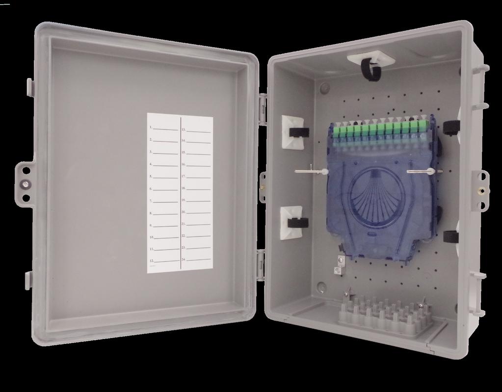
13 Installation Manual Using the Flex Box Clearview Blue Cassette (Up to 24 ports) Fiber management is provided for both incoming and outgoing fiber in separate areas to reduce service interruptions when turning up additional subscribers. 1. Place all 4 of the fiber management radius limiters onto the Flex Box, in the designated holes as shown in (Figure 1). 2. Place the 5 fiber management blocks as shown in (Figure 2). Figure 1 Figure 2 13
 into pems, located in base of wall box.")

 Note: If configuration includes In-Cassette Splicing, follow")

14 Installation Manual 3. Place the two threaded rods (screw in) into pems, located in base of wall box. (Figure 3) 4. Slide cassettes onto threaded rods, utilizing the holes in side rail of cassettes and place nylon nuts to secure. (Figure 4) Note: If configuration includes In-Cassette Splicing, follow procedures outlined in Clearview Blue Cassette Manual for preparing and splicing, then complete STEP 4 above. Figure 3 5. If needed, up to 40 feet of 3mm jacket incoming fiber can be stored within the fiber management radius limiters, as shown in (Figure 5), then slide cassettes onto rods to secure into Flex Box. Figure 4 Figure 5 14
 for tying off pullstring when waiting to pull fiber (Figure 6). 2.")
15 Installation Manual 1. Place screw hook into a convenient location (hole) for tying off pullstring when waiting to pull fiber (Figure 6). 2. Flex Box is now ready to accept fiber (Figure 7). Note: Cassette can be mounted in either direction. Figure 6 or Figure 7 15
. 2. Using provided screws, secure plate to box as shown (Figure 2). 3.")
 with (2) 14/10mm and (24) 10/6mm ports arrives from the factory with (1) 14/10mm FlexPort and the appropriate number of 10/6mm")

16 Installation Manual Using the Aggregator Plates Depending on the configuration, the Flex Box is available with 2 different style slide-in aggregator plates, supporting multiple cable entries. 1. Slide plate into base of Flex Box, aligning into the groove as shown (Figure 1). 2. Using provided screws, secure plate to box as shown (Figure 2). 3. For OUTDOOR APPLICATIONS, apply silicon bead onto aggregator plate before sliding into groove. Figure 1 Figure 2 The Duct Plate (Figure 3) with (2) 14/10mm and (24) 10/6mm ports arrives from the factory with (1) 14/10mm FlexPort and the appropriate number of 10/6mm FlexPorts matching port count Figure 3 These FlexPorts will be marked on the opposite side, tabs with a black X, indicating that the port has a FlexPort installed to accept microduct. Clearfield recommends the following port assignment. Working from back (bottom in Figure 3): 1-6, then moving up to next row 7-12 etc. Note: DO NOT place microduct into port WITHOUT a FlexPort installed or this box will not be water tight. 16

.")
17 Installation Manual Using the COMBO Aggregator Plates COMBO Plate (Figure 1) with (24) 10/6mm ports. Also has the ability to have field installed FlexPort, sealcons or conduit fittings. Note: Max hole size is 1.25 (to keep integrity of the plate intact). Place conduit fitting (Figure 2) or Sealcon (Figure 3). Figure 1 Additional FlexPorts can be added in the field utilizing the 9 match points (Figure 4). Figure 2 Figure 3 Figure 4 17

.")

 3.")
.")

18 Installation Manual Installing Microduct into Aggregator Plate 1. Using a pair of pliers, snap off tab of desired FlexPort (marked with black X ). (Figure 1) Figure 1 2. De-burr port, using the de-burring tool as shown, or snips/knife, to remove any sharp edges. (Figure 2) 3. Push pull string through port, tie off to the screw hook (previously placed). (Figure 3) 4. Properly prepare microduct, (flush cut and de-burr, then insert duct into FlexPort until snug). (Figure 4) Figure 2 Figure 3 Figure 4 18


 2.")

 14/10mm FlexPort Installation Insert O-ring,")

19 Installation Manual Installing Additional FlexPorts 10/6mm FlexPort Fitting 14/10mm FlexPort Fitting O-Ring FlexPorts are factory installed into aggregator plates that come from the factory based on the port count specified at time of order. When needed, FlexPorts can be added in the field to allow the terminal to accept additional microduct. Green Spacer Shark Tooth Ring Collar 1. Locate and, using pliers, remove tab associated to the 10mm or 14mm port that you will use. (Figure 1) 2. De-burr (using a de-burring tool/snips/knife) the port hole for a smooth transition without damaging the fiber as it enters the port. (Figure 2) 14/10mm FlexPort Installation Insert O-ring, then Spacer Note: MUST BE FULLY DE-BURRED FOR MPO 3. Following the diagram, place parts as shown. (Figure 3) Press in Ring (smooth side up) Figure 1 CORRECT INCORRECT Press in Collar Figure 2 Figure 3 19


 Outdoor in Duct Yes in Duct -40 to 176 F Yes Black Yes For use")

20 Installation Manual DROP CABLE OPTIONS Product Name FieldShield FLATdrop Cable Jacket UV Temperature FieldShield Connector Jacket Color Can be stapled Outdoor Yes -40 to 176 F No Black Yes Best Application For use when fast installation and low up-front cost is most desired feature. FieldShield D-ROP Outdoor Yes -40 to 176 F Yes Black/ Orange Yes For use when a single pass and restorable solution at a competitive price is ideal. FieldShield FLEXdrop Indoor (Plenum Rated)/ Outdoor Yes -40 to 176 F Yes Black/ White Yes For use when a premium product that has maximum workability, flexibility and restorability is desired. FieldShield (Classic) Outdoor in Duct Yes in Duct -40 to 176 F Yes Black Yes For use when the distance from the access point to the SFU/MDU is longer than normal and a more rigid solution is required to maintain restorability for drops longer than 300 feet. FieldShield StrongFiber Indoor/ Outdoor in Duct Yes in Duct -40 to 176 F Yes Black Yes in Duct For use when a reusable pathway is needed and maximum slack storage is desirable. 20


21 Installation Manual Connector Cleaning Procedure Whether factory terminated or field spliced, clean connectors are essential for proper system operation. Even the smallest dust particle can cause transmission problems, so for optimal network performance, inspect and if necessary, clean all connectors and adapters prior to mating. I.T.C Inspect Then Connect! ALWAYS inspect the connector first thing with a clean fiber scope inspect the pair. Three types of contamination require different cleaning techniques. The use of Chemtronics end face and bulkhead cleaning products and techniques ensures a clean end face, no matter the type of contamination. These are Clearfield recommended products/application. Use the product you feel will complete your cleaning procedures. Create a best practice for your company and follow those procedures. Figure 1 **Note: It is NOT recommended to use IPA to clean the end-face. Cleaning the end-face but not just the end-face Place one wiping paper on QbE-2 FiberSafe Cleaning Platen. Figure 1 Apply small amount of precision cleaner (about 1 in diameter) with Electro-Wash MX pen on to one end of the wipe. Figure 2 Figure 2 Hold end face 90 degree. Adjust for APC connection by slightly tilting the container or end face. Angle is correct when no drag is left on the end face. Figure 3 Draw end face from wet to dry part of the wipe 3 times. Use just enough pressure to ensure complete contact between end face and the wipe. DO NOT retrace previous step. Figure 3 21
 by spotting a small amount (about 1 ) of Electro-Wash PX or Electro-Wash MX pen onto the QBE-2. Hold the swab, 1 side down to the wetted area and hold for a count of 1-2-3-4-5.")


22 Installation Manual CLEAN THE FERRULE Lightly moisten the fiber optic swab (2.5mm/38542F or 1.25mm/38040) by spotting a small amount (about 1 ) of Electro-Wash PX or Electro-Wash MX pen onto the QBE-2. Hold the swab, 1 side down to the wetted area and hold for a count of Figure 4 Insert swab into side of ferrule, wet side to the ceramic ferrule and circle around 2-3 times and remove. Turn swab to dry side and repeat. Figure 5 Cleaning the mate through a bulkhead adapter AND the adapter itself! Figure 4 Lightly moisten the fiber optic swab(2.5mm/38542f or 1.25mm/38040) by spotting a small amount (about 1 ) of Electro-Wash PX or Electro-Wash MX pen onto the QBE-2. Hold the tip of the swab onto the wetted area and hold for a count of Insert the swab into the adapter to the connector, press lightly against the connector, twist 2-3 times, remove and discard. Dry with a second dry swab. Figure 5 Inspect (re-clean if necessary) and test for signal strength. Use additional swabs to clean inside the actual adapter. Moisten swab, like above, insert through hole and remove while twisting. Figure 6 Figure 6 22

.")
23 Installation Manual Cleaning an MPO/MTP Connector Female Connector Place one wiping paper on QbE-2 FiberSafe Cleaning Platen and apply small amount of precision cleaner (about 1 in diameter) with Electro-Wash MX pen on to one end of the wipe. Figure 1 Hold end face 90 degree. Adjust for APC connection by slightly tilting the container or end face. Angle is correct when no drag is left on the end face. Figure 2 Figure 1 Male Connector Lightly moisten the fiber optic swab (CC505F) like above, moistening 1 side. Place swab, wet side down at one end of connector end-face and draw across in a diagonal sweep (ie: from fiber 1 up and across to fiber 12). Turn swab over to dry and draw back from fiber 12 to fiber 1. Figure 3 Figure 2 BEFORE cleaning any connector be sure you know what type of contaminate you are cleaning dry? Fluidic?...All the available products are good, it s the process that you need to be aware of. Using a dry cleaning method to clean dirt can lead to scratching of the end-face. Learn the process of cleaning properly! Figure 3 23
24 Installation Manual Standard Warranty Clearfield warrants to the original purchaser of the Product sold hereunder is free from defects in material and workmanship under normal use and service, subject to exceptions stated herein. Product purchased is warranted as follows: Clearfield designed and branded Products are warranted for three (3) years: Products manufactured by Clearfield to customer prints and/or specifications are warranted for one (1) year; and any Product Clearfield acquires from or through a third-party manufacturer or distributor and resells to Customer as the original customer will carry the manufacturer s pass-through warranty, if any. In all cases, the warranty period commences on the date of shipment to the original purchaser. Warranty Claim Procedure If any Product purchased from Clearfield is found defective under the above warranty, the following basic procedure must be followed: 1. Customer must contact Clearfield and obtain a Return Materials Authorization. 2. Following authorization, the Customer ships the product-freight collect-to Clearfield s manufacturing facility. 3. Clearfield shall repair or replace the defective Product at its sole option and discretion, and return the repaired or replacement Product to Customer s site, freight prepaid. Note: If the Product is not found to be defective by Clearfield, the product will be returned to the Customer and the customer billed for freight in both directions. View our warranty policy here: Limitations of Warranty Correction of defects by repair or replacement, at the option of Clearfield Inc, shall constitute the exclusive sole remedy for a breach of this limited warranty. Clearfield shall not be liable under any circumstances for any special, consequential, incidental, punitive, or exemplary damages arising out of or in any way connected with the product or with agreement to sell product to buyer, including, but not limited to damages for lost profits, loss of use, or for any damages or sums paid by buyer to third parties. The foregoing limitation of liability shall apply whether the claim is based upon principles of contract, warranty, negligence or other tort, breach of statutory duty, principles of indemnity or contribution, the failure of any limited or exclusive remedy to achieve its essential purpose, or otherwise. Clearfield will not be responsible for any labor or materials costs associated with installation or incorporation of Clearfield products at customer sites, including any costs of alteration, replacement or defective product, or any field repairs. Other Limitations Clearfield assumes no warranty liability regarding defects caused by: 1. Customer s modification of Product, excepting installation activities described in Clearfield documentation. 2. Customer re-packaging of Product for shipment to third parties or destinations other than those originally shipped to by Clearfield, or any defects suffered during shipping where the Product has been re-packaged. 3. Customer s installation or maintenance, excepting activities described in and performed in accordance with Clearfield documentation 4. Customer s improper or negligent use or application of Product. 5. Other causes external to the Product, including but not limited to accidents, catastrophe, acts of God, government action, war, riot, strikes, civil commotion, sovereign conduct, or the acts or conduct of any person or persons not party to or associated with Clearfield. 6. Environmental factors and weathering resulting in aging and damage not necessary or applicable to the function of the product. 24
25 Installation Manual Proprietary Notice Information contained in this document is copyrighted by Clearfield, Inc. and may not be duplicated in full or part by any person without prior written approval of Clearfield, Inc. Its purpose is to provide the user with adequately detailed documentation to efficiently install the equipment supplied. Every effort has been made to keep the information contained in this document current and accurate as of the date of publication or revision. However, no guarantee is given or implied that the document is error free or that it is accurate with regard to any specification. Technical Support Clearfield, Inc. can be contacted for any issues that arise with the supplied product. If you need to return the supplied product, you must contact the Clearfield, Inc. Customer Service Department to request a Returned Materials Authorization (RMA) number. Clearfield, Inc Winnetka Ave N Minneapolis, MN Toll Free: Phone: Fax: Customer Support: sales@clfd.net Technical Support: techsupport@clfd.net 25
FieldShield YOURx-TAP Installation Manual
 Installation Manual Installation Manual Table of Contents Product Packaging 3 Parts List 3 Required Tools 4 Box Mounting 4 Preparing Ports 5 Bottom Deploy Reel Installation 5 Configurations 8 Top Deploy
CraftSmart Test Access Point (TAP) Box Installation Manual
 Box Installation Manual") Installation Manual Installation Manual Table of Contents Application 3 Description 3 Technical Specifications 3 TAP Box Assembly 4 TAP Box Mounting 8 Cable Entrance 10 Grounding 11 Strength Member Clamp
Installation Manual Installation Manual Table of Contents Application 3 Description 3 Technical Specifications 3 TAP Box Assembly 4 TAP Box Mounting 8 Cable Entrance 10 Grounding 11 Strength Member Clamp
YOURx-Aerial Terminal Installation Manual
 Installation Manual Installation Manual Table of Contents Application 3 Description 3 Technical Specifications 3 Components 4 Parts List 5 Recommended Tools 6 Strand Mounting 7 Accessing the YOURx-Aerial
JD2800 Module Installation Guide
 Up to 30% More Horsepower 10-20% Fuel Savings John Deere 9.0L Tier III Denso Common Rail Engines JD2800 Module Installation Guide AgDieselSolutions.com Ground Terminal Power (+12V constant) Terminal Injector
Read all instructions before installing and using. Installer: This manual must be delivered to the end user.
 Installation Instructions Vacuum / Magnet Mount Kits IMPORTANT! Read all instructions before installing and using. Installer: This manual must be delivered to the end user.! WARNING! Failure to install
Adjustable Angled Incline Conveyor Owners Manual with Operating Instructions
 Adjustable Angled Incline Conveyor Owners Manual with Operating Instructions Revision 012211 Table of Contents Basic Conveyor Features 3 Getting Started 4 Setting Up the Incline Conveyor 5 Belt Removal
MEX (55) QRO (442) Web Controls
 QRO (442) Web Controls") Web Controls SINGLE AND DUAL ROTOR TENSION CONTROL BRAKES MODELS:,,,, AND INSTALLATION, OPERATION, AND MAINTENANCE INSTRUCTIONS Read this manual carefully, making full use of its explanations and instructions.
Web Controls SINGLE AND DUAL ROTOR TENSION CONTROL BRAKES MODELS:,,,, AND INSTALLATION, OPERATION, AND MAINTENANCE INSTRUCTIONS Read this manual carefully, making full use of its explanations and instructions.
EZ-R7 T-Plug. Universal 7-Pin Heavy Duty Plug For Vehicles equipped with 7-Way Trailer Connectors. Installation Instructions and Product Warranty
 EZ-R7 T-Plug Universal 7-Pin Heavy Duty Plug For Vehicles equipped with 7-Way Trailer Connectors Installation Instructions and Product Warranty Professional Installation Required Thank you for purchasing
AGCO. Corn Header Manual d HEADSIGHT.COM
 AGCO Corn Header Manual 09020401d HEADSIGHT.COM 574.546.5022 About Headsight Headsight Contact Info Headsight, Inc. 4845 3B Road Bremen, IN 46506 Phone: 574-546-5022 Fax: 574-546-5760 Email: info@headsight.com
Installation Instructions SRC Over-Size Tire Carrier Jeep Wrangler/Unlimited Part # 2743
 NOTE: Carefully read instructions entirely before assembling/installing this product. Parts Included Qty Parts Included Qty Tire Carrier 1 8 x 70mm Hex Bolt 4 Brake Light Bracket 1 8mm Flat Washer 4 Tire
MODEL 5120 Tire Repair Station
 MODEL 5120 Tire Repair Station 00-0049 Installation, Operation & Repair Parts Information Branick Industries, Inc. 4245 Main Avenue P.O. Box 1937 Fargo, North Dakota 58103 REV01182017 P/N: 81-0058G CAUTION
Instruction Sheet SRSR SERIES. Rotating Sliding Rail System
 Instruction Sheet SRSR SERIES Rotating Sliding Rail System THANK YOU Thank you for purchasing the SRSR Series Rotating Sliding Rail System. Please read these instructions thoroughly before assembling this
Level Alert Model Multi-Switch Liquid Level Sensor. Assembly and Installation Instructions
 Level Alert Model 2000 Multi-Switch Liquid Level Sensor Assembly and Installation Instructions Kit Form Each unit is provided in kit form with step-by-step instructions, making it extremely easy to custom
I N S TA L L AT I O N
 I N S TA L L AT I O N 5008 fits: H-D: '80-Up Electra glide, tour glide, road king, road glide or street glide PartS Included 1 Right Fork Mount Assembly 1 Left Fork Mount Assembly 2 H3 Driving Light Assemblies
INSTALLATION & OPERATING INSTRUCTIONS: REVOLUTION SPINEBOARD ATTACHMENT WARNING
 INSTALLATION & OPERATING INSTRUCTIONS: REVOLUTION SPINEBOARD ATTACHMENT LOAD CAPACITY: 500 LBS [227 kg] MANDATORY: LEAVE THIS MANUAL WITH LIFT OWNER WARNING 1. READ AND FOLLOW ALL INSTRUCTIONS. LIFT SAFETY
MODEL EF Full Circle Tire Spreader
 MODEL EF Full Circle Tire Spreader Installation, Operation & Repair Parts Information Branick Industries, Inc. 4245 Main Avenue P.O. Box 1937 Fargo, North Dakota 58103 REV. 062917 P/N: 81-0050C CAUTION
Slimline Duals Installation Instructions Harley-Davidson Touring Models 2009-Current
 Slimline Duals Installation Instructions Harley-Davidson Touring Models 2009-Current Thank you for buying a Rinehart Racing exhaust system. We are committed to providing premium products that with proper
CU6703 Module Installation Guide
 Up to 30% More Horsepower 10-20% Fuel Savings Cummins 6.7L Tier III Engines CU6703 Module Installation Guide AgDieselSolutions.com MAP sensor male and female connectors. Power and Ground wires. Module
"WHERE TUBING AND FITTINGS COME TOGETHER"
 CLEAN ROOM DEVICES, LLC "WHERE TUBING AND FITTINGS COME TOGETHER" CRD200SS TUBE EXPANDER OPERATIONS MANUAL VERSION 4.3 LAST EDITED 06.17.15 cleanroomdevices.com Table of Contents Table of Contents....1
SOLAR BOLT CHARGING SYSTEM INSTALLATION GUIDE
 CHARGING SYSTEM Doc 1.00 INST052 1 SOLAR BOLT CHARGING SYSTEM CONTENTS General Information... 2 Solar Panel Installation... 3 Solar Bolt Main Harness and Indicate Installation... 4 Cable Routing... 9 Solar
Read and follow all instructions. Safety can only be ensured if the walker is assembled and operated according to these instructions.
 Aqua Walker 9889 Garrymore Ln Missoula, MT 59808 888-687-3552 +1-406-549-0769 www.aquacreek.com Manual PART #: F-605UW 300 LB. [136 kg] MAXIMUM WEIGHT CAPACITY MANDATORY LEAVE THIS MANUAL WITH WALKER OWNER
Operating and Installation Instructions
 Model Number 20902 Fabricator's Power Module Kit - Aluminum Operating and Installation Instructions CAUTION! This product is to be installed only by persons knowledgeable in the repair and modification
Cabling for power, control, and video must be run to the installation site before the mount is installed.
 User Installation User Guide Guide & Operation Manual V940D V-20B-A-2 V940D Mounting Kits Mounting Pole Mounting Kits Adapter X532-11-00 Vicon Industries Inc. does not warrant that the functions contained
INSTALLATION INSTRUCTION & OWNER S MANUAL
 CS-2500 & CS-2500P Water Filtration System INSTALLATION INSTRUCTION & OWNER S MANUAL Ver 1.2 All Rights Reserved APEC Water Systems Please keep this Owner s Manual for future reference. It contains useful
37SCENE 46SCENE 79SCENE
 Installation and Operation Instructions LED SCENE LIGHT LED SCENE LIGHT 37SCENE 46SCENE 79SCENE 37SCENE 46SCENE Introduction The 37SCENE, 46SCENE, 79SCENE LED Scene Lights are designed for the emergency
GERINGHOFF. Corn Header Manual f HEADSIGHT.COM
 GERINGHOFF Corn Header Manual 09020701f HEADSIGHT.COM 574.546.5022 About Headsight Headsight Contact Info Headsight, Inc. 4845 3B Road Bremen, IN 46506 Phone: 574-546-5022 Fax: 574-546-5760 Email: info@headsight.com
Cardinal DETECTO. PORTABLE PLATFORM SCALES Digital Type Series 850F Owner s Manual
 Cardinal DETECTO PORTABLE PLATFORM SCALES Digital Type Series 850F Owner s Manual CARDINAL SCALE MFG. CO. PO BOX 151, WEBB CITY, MO 64870 0066-M176-O1 Rev H 10/06 417-673-4631 www.cardinalscale.com Printed
Installation Instructions Trektop NX
 Installation Instructions Trektop NX Vehicle Application: Jeep Wrangler (JK) 2 Door 2007 Current Part Number: 56822 www.bestop.com - We re here to help! Visit our web site and click on Ask a Question.
EZ Carrier 3. Owner s Manual. Keep instructions for future reference
 EZ Carrier vv Owner s Manual Keep instructions for future reference Introduction The EZ Carrier provides all the flexibility you may need to transport your mobility scooter. The features include: The capability
Cummins N14 Celect & Celect Plus Engine Module. For Agricultural Applications Only. Part # 31200
 1994-2003 Cummins N14 Celect & Celect Plus Engine Module For Agricultural Applications Only Part # 31200 31200_revA Adjustable Switch Agricultural Cummins N14 Engine Module Power and Ground terminals Timing
CRD610 Automatic Fitting Inserter
 CRD610 Automatic Fitting Inserter OPERATIONS MANUAL VERSION 1.2 LAST EDITED 12.12.2018 cleanroomdevices.com 1 Table of Contents Title Page. 1 Table of Contents...2 1.0 General Product & Safety Information....3
Straight-Bore Clutch LSCC-32, 44, 54
 Straight-Bore Clutch LSCC-32, 44, 54 1 In accordance with Nexen s established policy of constant product improvement, the specifications contained in this manual are subject to change without notice. Technical
Installation Instructions Trektop NX
 Installation Instructions Trektop NX Vehicle Application: Jeep Wrangler (JK) 2 Door 2007 Current Part Number: 56822 www.bestop.com - We re here to help! Visit our web site and click on Ask a Question.
INSTALLATION INSTRUCTIONS
 INSTALLATION INSTRUCTIONS Thank you for purchasing ACCESS Original Roll-Up Cover. Agri-Cover, Inc. proudly manufactured this cover using superior quality materials and workmanship. With proper care, your
Harley Davidson FL Touring Current Xtreme
 ITEMS SUPPLIED Description Part # Qty Front Header (Chr/Blk) 100-0119/100-0123 1 Rear Header (Chr/Blk) 100-0120/100-0124 1 Front Heat Shield (Chr/Blk) 100-0121/100-0125 1 Rear Heat Shield (Chr/Blk) 100-0122/100-0126
Installation Instructions Rear Shell Roof Rack
 Installation Instructions Rear Shell Roof Rack Vehicle Application: Jeep Wrangler 1986 current Part Number: 41400 www.bestop.com - We re here to help! Visit our web site and click on Ask a Question. Click
Installation Instructions Supertop NX Twill
 Installation Instructions Supertop NX Twill Vehicle Application: Jeep Wrangler Unlimited 2007 Current Part Number: 54823 www.bestop.com - We re here to help! Visit our web site and click on Ask a Question.
CLEAN ROOM DEVICES, LLC "WHERE TUBING AND FITTINGS COME TOGETHER"
 CLEAN ROOM DEVICES, LLC "WHERE TUBING AND FITTINGS COME TOGETHER" CRD600AF Automatic Fitting Inserter With Auto Feed OPERATIONS MANUAL (Shown with optional alcohol dispenser) 1 VERSION 1.1 LAST EDITED
Installation & Maintenance of the Fresh-Aire UV Airborne Duct System for Commercial HVAC Systems. Parts Included. Optional Parts
 Installation & Maintenance of the Fresh-Aire UV Airborne Duct System for Commercial HVAC Systems The Fresh-Aire UV Airborne Duct System is designed for installation into commercial HVAC system ducts for
DRAGO. Corn Header Manual f HEADSIGHT.COM
 DRAGO Corn Header Manual 09020801f HEADSIGHT.COM 574.546.5022 About Headsight Headsight Contact Info Headsight, Inc. 4845 3B Road Bremen, IN 46506 Phone: 574-546-5022 Fax: 574-546-5760 Email: info@headsight.com
7.3L POWERSTROKE BANJO BOLT KIT Fits L Powerstroke Diesel. Installation Guide
 7.3L POWERSTROKE BANJO BOLT KIT Fits 94-03 7.3L Powerstroke Diesel Installation Guide INSPECT CONTENTS OF THIS KIT THOROUGHLY BEFORE STARTING THE INSTALLATION PROCESS! IF YOU FIND A PROBLEM WITH YOUR PACKAGE:
Deluxe Hitch 3-Bike Rack Instructions for Part # BC-3581
 General Guidelines Deluxe Hitch 3-Bike Rack Instructions for Part # BC-3581 It is the user s responsibility to read and follow all instructions. Keep these instructions with the product at all times and
CRD600 Automatic Fitting Inserter
 CRD600 Automatic Fitting Inserter OPERATIONS MANUAL VERSION 2.3 LAST EDITED 12.07.2018 cleanroomdevices.com 1 Table of Contents Title Page.. 1 Table of Contents. 2 1.0 General Product & Safety Information...3
Installation Instructions Supertop NX
 Installation Instructions Supertop NX Vehicle Application: Jeep Wrangler Unlimited 2007 Current Part Number: 54723 www.bestop.com - We re here to help! Visit our web site and click on Ask a Question. Click
CLEAN ROOM DEVICES, LLC "WHERE TUBING AND FITTINGS COME TOGETHER"
 CLEAN ROOM DEVICES, LLC "WHERE TUBING AND FITTINGS COME TOGETHER" CRD600 Automatic Fitting Inserter OPERATIONS MANUAL VERSION 2.1 LAST EDITED 7.25.14 DOCUMENT NUMBER 001 cleanroomdevices.com 1 Table of
INSTALLATION INSTRUCTIONS
 INSTALLATION INSTRUCTIONS Thank you for purchasing VANISH Roll-Up Cover. Agri-Cover, Inc. proudly manufactured this cover using superior quality materials and workmanship. With proper care, your cover
DynaCon Instruction Manual
 DynaCon Instruction Manual Table of Contents Technical Specification & Warranty.... 3 Construction, Benefits & Safe Operating Procedures... 4 Noise Levels... 5 Installation, Operation & Maintenance...
2 Piece Soft Door Installation Instructions
 2 Piece Soft Door Installation Instructions For: Wrangler/TJ (1997-on) Part Number: 51789 Note: Use of this product will eliminate the factory side mirrors and requires the removal of the entry light bulbs.
Installation Instructions Supertop NX
 Installation Instructions Supertop NX Vehicle Application: Jeep Wrangler JK 2 Door 2007 Current Part Number: 54722 www.bestop.com - We re here to help! Visit our web site and click on Ask a Question. Click
Installation Manual. Model 300SS-M. Moisture Only Kit for Small Square Balers 300SS-16-INST-M 3/17 1
 Installation Manual Model 300SS-M Moisture Only Kit for Small Square Balers 300SS-16-INST-M 3/17 1 (intentionally blank) 2 300SS Installation Manual Table of Contents Page Introduction 4 System Requirements
Pump/Manifold Kits. Instructions F ENG. To convert E-Flo 4-Ball Piston Pumps to a different size lower. For professional use only.
 Instructions Pump/Manifold Kits 311611F ENG To convert E-Flo 4-Ball Piston Pumps to a different size lower. For professional use only. See page 2 for a list of available kits. Important Safety Instructions
DAP-625S and DAP-875S
 AIR CHAMP PRODUCTS DAP-625S and DAP-875S (i) FORM NO. L-20078-B-0501 In accordance with Nexen s established policy of constant product improvement, the specifications contained in this manual are subject
PART NUMBER: F-706RLSS REVOLUTION LIFT: SLING-SEAT OPTION
 PART NUMBER: F-706RLSS REVOLUTION LIFT: SLING-SEAT OPTION 500 LB. [227 kg] MAXIMUM CAPACITY MANDATORY LEAVE THIS MANUAL WITH LIFT OWNER - WARNING- IMPORTANT SAFETY INSTRUCTIONS 1. READ AND FOLLOW ALL INSTRUCTIONS.
Installation Instructions
 Installation Instructions Trektop Doors not included Vehicle Application Jeep Wrangler Unlimited 2007 2011 Part Number: 56805 www.bestop.com - We re here to help! Visit our web site and click on Ask a
This sheet must be read completely to:
 Instalation Preparation This sheet must be read completely to: 2. Avoid causing injury to installer, customer, end user, or others. 3. Prevent damage to ATV, UTV, and Motorcycle and/or accessory. 4. Prevent
EZR7 Universal 7-Pin Heavy Duty Plug Installation Instructions and Product Warranty Professional Installation Required
 EZR7 Universal 7-Pin Heavy Duty Plug Installation Instructions and Product Warranty Professional Installation Required Thank you for purchasing our EZ-U7PHD trailer plug! Your choice displays your recognition
SOLAR DASH CHARGING SYSTEM USER GUIDE
 SOLAR DASH CHARGING SYSTEM Doc 1.01 INST049 INSTALLATION STEP 1 Place 20 watt solar panel in the dash of the vehicle facing up. Note: For ideal results position the vehicle in a manner in which the solar
AEROMOTIVE Part # INSTALLATION INSTRUCTIONS
 AEROMOTIVE Part # 14102 INSTALLATION INSTRUCTIONS CAUTION: Installation of this product requires detailed knowledge of automotive systems and repair procedures. We recommend that this installation be carried
JD Flex. Header Manual c
 JD Flex Header Manual 09030101c About Headsight Headsight Contact Info Headsight, Inc 3529 Fir Road Bremen, IN 46506 Phone: 574-546-5022 Fax: 574-546-5760 Email: info@headsight.com Web: www.headsight.com
Fitting Instruction for EZI-GRIP Bike Rack
 Fitting Instruction for EZI-GRIP Bike Rack Congratulations on purchasing Ezi-Grip to carry your valued bicycles. We are sure you will get many years of enjoyable use from your Ezi-Grip Bike Rack. These
ActuLink ABS Module - ABS-MOD-400
 Installation Instructions ActuLink ABS Module - ABS-MOD-400 For more information on the installation and operation of Tuson s towable ABS system, consult the installation and operations manuals for the
Model P-40 & Model P-25 POWER PUSHER
 Power Pusher Description INSTRUCTION MANUAL The Power Pusher provides ram capability by using the spreading power of the POWER HAWK P-16 Rescue Tool. (The Power Pusher may also be used with other spreader
EASY CONNECT CRANE KIT Festoon Conductor Systems
 ASSEMBLY INSTRUCTION MANUAL EASY CONNECT CRANE KIT Festoon Conductor Systems October, 2005 Copyright 2005, Yale Lift-Tech, division of Columbus McKinnon Corporation Part No. 117463-05 Mounting Instructions
CLEAN ROOM DEVICES, LLC "WHERE TUBING AND FITTINGS COME TOGETHER"
 CLEAN ROOM DEVICES, LLC "WHERE TUBING AND FITTINGS COME TOGETHER" CRD400 Fitting Inserter OPERATIONS MANUAL VERSION 3.1 LAST EDITED 03.08.11 DOCUMENT NUMBER 001 cleanroomdevices.com 1 Table of Contents
TBM Series 3-Way Ball Valve
 www.simtechusa.com TBM Series 3-Way Ball Valve Operating, Installation, & Maintenance Manual Corrosion Resistant Fluid and Air Handling Systems. Dated 06-26-13 TBM Series Ball Valves SIMTECHRECOMMENDSREADINGTHEFOLLOWINGINFORMATIONPRIORTOINSTALLINGANDUSING
Saf-T-Bar Conductor Bar T Series
 Saf-T-Bar Conductor Bar T Series P/N 964001 2012.04.12 Rev. 6 SERIES T SAF-T-BAR CONDUCTOR BAR 1 Conductix Incorporated The technical data and images which appear in this manual are for informational purposes
8400 Series Fiber Distribution System
 8400 Series Fiber Distribution System Instructions January 1997 34-7041-4699-1-A 1 Contents: 1.0 General... 3 2.0 System Components... 4 3.0 System Engineering... 5 4.0 Hardware Installation... 7 5.0 Cable
GM 6.6L Duramax. Up to 90HP Gain. AgDieselSolutions.com
 21700 Module Installation Guide 2017 GM 6.6L Duramax *L5P* Up to 90HP Gain 1-3 MPG Fuel Savings AgDieselSolutions.com Adjustable Switch Female Fuel Pressure Sensor Connector Male Fuel Pressure Sensor Connector
48" and 52" Hyflo Fans Installation and Operators Instruction Manual
 48" and 52" Hyflo Fans Installation and Operators Instruction Manual Thank You The employees of Chore-Time Equipment would like to thank your for your recent Chore-Time purchase. If a problem should arise,
CORN HEADER MANUAL: CNH PRE-2012
 CORN HEADER MANUAL: CNH PRE-2012 09020201c HEADSIGHT.COM 574.546.5022 About Headsight Headsight Contact Info Headsight, Inc. 4845 3B Road Bremen, IN 46506 Phone: 574-546-5022 Fax: 574-546-5760 Email:
Through-Shaft Clutch-Brake LSCB-32HT, LSCB-32HT, LSCB-44, LSCB-44HT, LSCB-54HT FORM NO. L D-0606 MEX (55) QRO (442)
 QRO (442)") Through-Shaft Clutch-Brake LSCB-HT, LSCB-HT, LSCB-, LSCB-HT, LSCB-5HT In accordance with Nexen s established policy of constant product improvement, the specifications contained in this manual are subject
Through-Shaft Clutch-Brake LSCB-HT, LSCB-HT, LSCB-, LSCB-HT, LSCB-5HT In accordance with Nexen s established policy of constant product improvement, the specifications contained in this manual are subject
Mechanical System Hanger
 D U C T M A T E U.S. Patent No. 7,222,824 Mechanical System Hanger Seismic Tested & Conforms to ICC Code Guidelines EG284 May be used on a variety of mechanical systems Steel Cable & Clutcher mechanism
Elgin Hydraulic Clutch-Brake ECB-240, Product Number FORM NO. L F FORM NO. L F-0704
 Elgin Hydraulic Clutch-Brake ECB-20, Product Number 96225 FORM NO. L-20283-F-070 1 FORM NO. L-20283-F-070 In accordance with Nexen s established policy of constant product improvement, the specifications
Instruction Sheet DWRSR-ZL. Zero Clearance Latch
 Instruction Sheet DWRSR-ZL Zero Clearance Latch US Patent 7,188,570 B2 THANK YOU Thank you for purchasing the DWRSR-ZL Zero Clearance Latch. Please read these instructions thoroughly before installing
TK08 TUNING KIT TECHNICAL MANUAL FOR 16/26/27/28 SERIES SHOCKS Revised 6/17/14
 Tech Line: (952) 985-5675 Fax (952) 985-5679 21730 Hanover Ave. Lakeville, MN 55044 www.qa1.net www.facebook.com/qa1motorsports TK08 TUNING KIT TECHNICAL MANUAL CONTENTS UNDER PRESSURE! USE EXTREME CAUTION
Installation Power Management Unit Battery Cables and Battery Harness
 Installation Power Management Unit Battery Cables and Battery Harness Important Safety Messages SAVE THESE INSTRUCTIONS - This manual contains important instructions that should be followed during installation
Single Post Caliper Brake VC500
 Single Post Caliper Brake VC500 1 In accordance with Nexen s established policy of constant product improvement, the specifications contained in this manual are subject to change without notice. Technical
Installation Instructions For: Suzuki Samurai, All Years Part Number: TM
 Installation Instructions For: Suzuki Samurai, All Years Part Number: 51761 TM Patent Pending WARNING This product is designed to enhance the appearance of the vehicle and to shield the occupants from
Guardian Steel Gear Shaft Coupling
 Guardian Steel Gear Shaft Coupling P-8609-GC GUA-MRK-DOC-026 Service & Installation Instructions TABLE OF CONTENTS NOTICES AND WARNINGS PAGE 2 SECTION 1 COUPLING OVERVIEW PAGE 3 SECTION 2 TOOLS/MATERIALS
FCB-450, LCB-600, MCB-800
 AIR CHAMP PRODUCTS User Manual FCB-450, LCB-600, MCB-800 Clutch-Brakes (i) In accordance with Nexen s established policy of constant product improvement, the specifications contained in this manual are
AEROMOTIVE Part # C5 Corvette Fuel Rail Kit INSTALLATION INSTRUCTIONS
 AEROMOTIVE Part # 14128 99-04 C5 Corvette Fuel Rail Kit INSTALLATION INSTRUCTIONS CAUTION: Installation of this product requires detailed knowledge of automotive systems and repair procedures. We recommend
Sample Pro 3/4" Portable MicroPurge Pump. User's Guide P/N REV The World Leader in Air Powered Pumps
 PATENT PENDING Pro 3/4" Portable MicroPurge Pump User's Guide P/N 959 REV. -8-03 The World Leader in Air Powered For Remediation, Landfills and Ground Water Sampling Ground water Sampling Remediation,
For: Model Year Jeep Wrangler/TJ Part Number: For: Model Year Jeep Wrangler/TJ Part Number: 58709
 TJ Tinted Window Kit Installation Instructions TM For: 1997-2002 Model Year Jeep Wrangler/TJ Part Number: 58609 For: 2003-2004 Model Year Jeep Wrangler/TJ Part Number: 58709 www.bestop.com Inc. DO NOT
Operating Instructions
 Operating Instructions WARNING: Do not attempt to assemble, connect to power source, or operate the Burrell Wrist-Action Shaker without first reading these instructions. Also assure that each person that
Installation Instructions TJ Tinted Window Kit
 Installation Instructions TJ Tinted Window Kit Vehicle Application: Jeep Wrangler TJ 1997 2006 Part Number: 58709 www.bestop.com - We re here to help! Visit our web site and click on Ask a Question. Click
SELECT -24 INSTALLATION GUIDE. INST036 Doc 2.02
 SELECT -24 INSTALLATION GUIDE INST036 Doc 2.02 CONTENTS General Information...2 Select-24 Diagram...3 Mounting the Select Controller...4 Dual Pole Nosebox Installation...5 Aux Harness Installation...6
Installation Instructions Trektop NX
 Installation Instructions Trektop NX Vehicle Application: Jeep Wrangler TJ 1997 2006 Part Number: 56820 www.bestop.com - We re here to help! Visit our web site and click on Ask a Question. Click here for
8" - 12" Hydraulic Steel Squeeze Off Tool
 8" - 12" Hydraulic Steel Squeeze Off Tool ECN 19130 C812S Hydraulic Steel Squeeze Off Tool for Steel Pipe Page 1 of 8 This Footage Tools C812S Steel Squeeze Off Tool is sold with one pump configuration
Stop! Read This Important Information.
 Stop! Read This Important Information. Stop, Do Not Proceed, Read This This door replacement kit is designed for the replacement of doors on a Supertop ONLY! This door will not work on any other style
Installation Guide. Marine Filter SURT023M SURT024M
 Installation Guide Marine SURT023M SURT024M suo0738a Product Description The APC by Schneider Electric Marine Application reduces the EMI (electro magnetic interference), produced by a connected that
Assembly Instructions
 TOOLS REQUIRED: _(2) 3/4 wrenches _7/16 wrench _3/8 wrench _5/16 allen wrench Display/work stand is for assembly procedure only. May be purchased separately. CONTENTS (PARTS & HARDWARE) _(1) Receiver tube
FADE Series Wall Axial Fans
 Installation and Operation Manual Item #: 401442 Rev Date: 070113 FADE Series Wall Axial Fans Fantech Inc. certifies that the FADE Series shown herein is licensed to bear the AMCA Seal. The ratings shown
Owner s Installation Guide
 Owner s Installation Guide Introduction The nophoto is a highly advanced smart detterent device designed to protect your license plate from flash photography. Using patented technology, the nophoto reacts
Mechanical Spiral Sensor
 Installation Manual Model 6005-1 Mechanical Spiral Sensor No part of this instruction manual may be reproduced, by any means, without the written consent of Geokon, Inc. The information contained herein
Web Volume Control Model WV220
 WEB CONTROL PRODUCTS User Manual Web Volume Control Model WV220 1 In accordance with Nexen s established policy of constant product improvement, the specifications contained in this manual are subject
Installation Instructions Supertop for Truck
 Installation Instructions Supertop for Truck Vehicle Application: Ford F-150 5.5 Ft. Styleside 2004 and newer Part Number: 76309 www.bestop.com - We re here to help! Visit our web site and click on Ask
18670, INSTALLATION INSTRUCTIONS
 18670, 19871 INSTALLATION INSTRUCTIONS WARNING! The fuel system is under pressure. Do not open the fuel system until the pressure has been relieved. Refer to the appropriate vehicle service manual for
INTRODUCTION INSTALLATION
 INTRODUCTION INSTALLATION, OPERATION & MAINTENANCE INSTRUCTIONS This instruction manual includes installation, operation and maintenance information for the figure G73 gear operator. The figure G73 is
User Manual SH Slag Removal Tool for use on laser cutting machines with minimum 1.25 between slats
 User Manual SH2 67087 Slag Removal Tool for use on laser cutting machines with minimum 1.25 between slats 1. Description The tool is moved along the slats on the bed of a laser machine to remove slag that
Installation Guide Document N Cleanroom Mirrors Copyright 2016 Terra Universal Inc. All rights reserved. Revised November 2016
 Document N0. 1800-09 Copyright 2016 Terra Universal Inc. All rights reserved. Revised November 2016 Terra Universal, Inc. TerraUniversal.com 800 S. Raymond Ave. Fullerton, CA 92831 TEL: (714) 578-6000