S54 Vanos Procedure (E46 M3)
|
|
|
- Roberta Johnston
- 6 years ago
- Views:
Transcription
1 S54 Vanos Procedure (E46 M3) The following information is provided for reference purposes only and should be used at your own risk In no event shall Beisan Systems, LLC or its members be liable for incidental, consequential, or special loss or damages of any kind however caused. Introduction Vanos is BMW s name for its variable valve timing units. Vanos units take on various shapes and design according to car year and model (engine model). The vanos discussed here is BMW part # It s a double vanos, meaning both the intake and exhaust valve timing is varied. This vanos unit is part of BMW 6-cylinder engine S54. This engine is incorporated into the M3 E , Z3 E36 M Roadster & M Coup 00-02, Z4 E85 M3.2 Roadster 05-08, Z4 E86 M3.2 Coup This vanos experiences multiple failures and related failures. A major chronic failure is the breakage of the exhaust camshaft sprocket hub vanos oil pump driver tabs. There are two tabs and one or both can break. This vanos, as with other performance engine vanos units, incorporates an oil pump to provide high oil pressure for the vanos function. The high oil pressure allows for quick and precise positioning of the vanos and engine timing. With this vanos the oil pump is driven by the exhaust camshaft. Due to the need to have the vanos exhaust piston positioned to the center of the camshaft, the oil pump driver is offset from the center. Thus two drivers 180 degrees apart are used to balance the drive. The vanos has an oil pump disk with two holes and the exhaust hub has two driver tabs that insert into the oil pump disk holes. One or both of the driver tabs can break and cause vanos malfunction and engine fault codes. A broken tab can stay lodged in the vanos oil pump disk hole or it can drop to the oil pan. In rare cases the tab can engage the chain and sprockets and cause engine damage. The oil pump driver tab is breaking either from excessive rotational pressure force or rattling hitting force. Inspection of the vanos oil pump disk holes shows wall indentations in the rotational and counter rotational tab engagement positions. The counter rotational indentations indicate a rattling hitting movement. A dynamic hitting movement can also produce significantly higher forces than a pressure force. This oil pump driver design was first used on the Euro S50 double vanos/engine. But the Euro S50 double vanos rarely encounters a tab breakage. Comparison of the Euro S50 double vanos and S54 designs shows design changes made for the S54. The S54 exhaust hub driver tab is lengthened by 3mm with 2.5mm used for new large chamfers. Also the oil pump disk hole diameter is increased by.7mm.
2 It is evident these changes were made to ease the installation of the vanos to the engine head. During this installation the vanos oil pump disk holes need to be aligned with the exhaust hub driver tabs and the disk holes inserted onto the tabs. Introducing large chamfers on the tabs and increasing the disk hole diameter eases the installation. The lengthening of the driver tab does not seem to cause any oil pump performance changes. The new oil pump disk holes are deep enough to accommodate the extra length and this extra length is mostly a chamfer and thus does not engage the hole wall. But the disk hole diameter increase can significantly affect the driver tab hitting issue. The Euro S50 double vanos oil pump disk hole diameter is 10.00mm and the tab width is This provides.40mm tab to hole side play. The S54 vanos oil pump disk hole diameter is 10.70mm and the tab width is 9.70mm. This provides 1.00mm tab to hole side play. This constitutes a two and a half multiple increase in tab to hole play from the Euro S50 design. This significant increase in free space can facilitate much higher hitting forces and thus is likely the cause of the tab breakage. A comparison of the Euro S50 double vanos and S54 vanos oil pump disk hole indentations shows the S54 can encounter notably deeper indentations in the oil pump rotational direction. The hole indentations cause to increase the tab to hole play and thus can further increase the tab hitting force. S54 cars that encounter the tab breakage usually show significant oil pump disk hole indentations in the rotational direction. BMW has been engaged regarding vanos problems in the past and has elected to not address the issues, No further development will be done. New (rebuilt) vanos units are being sold with the same oil pump disks with the same large diameter holes. BMW does not provide the vanos oil pump disk as a separate part. If the above hypothesis is correct, the simple answer to the tab breakage problem is to reduce the oil pump disk hole diameters. There are three potential approaches to accomplishing this. First, a sleeve can be inserted into the hole to reduce its diameter. In practice this has not worked well as the sleeve is indented into the existing hole indentations and the sleeve could crack due to this. Second, a new disk can be made. Metallurgical inspection of the disk center bushing indicates it is molecularly fused to the disk. This is a very special technique used by automotive manufacturers for camshaft and crankshaft bearings and is only made exclusively by a few companies in the world for auto manufacturers. The bushing is only.5mm thick and thus can t be replaced with a pressed in bushing without thickening it and changing other design aspects of the disk which make the approach non-viable. Third, new holes can be drilled in the disk at a 90 degree offset form the existing holes. The holes must be precisely 180 degrees from each other and precisely the same diameter for both driver tabs to engage the hole sides simultaneously. A vanos oil pump disk with newly driller smaller holes can be acquired through
3 Beisan Systems (bee-saan), The disk hole diameter is 9.80mm. This leaves.10mm play between the driver tab and hole sides and is a further decrease from the Euro S50 double vanos.40mm play. This play reduction is intended to eliminate the occasional tab breakage that occurs on the Euro S50 double vanos. It might also resolve the occasional oil pump seize and damage that can occur. This vanos piston seals and static seal O-rings, other than the small O-ring on the oil pressure restrictor, are made of the correct materials and don t experience premature failure. However over time and use the piston seal O-rings will experience notable compression set (flattening) and the Teflon rings will experience wear (loss of material). This can lead to degradation in performance. The static seal O-rings will also experience notable compression set and could eventually leak. Thus there is a need for a replacement seals solution for this vanos. A vanos seals/o-rings repair kit can be acquired through Beisan Systems (beesaan), It includes a vanos replacement set of OEM equivalent material Teflon rings and Viton O-rings. The following repair procedure also covers the installation of the Beisan S54 vanos sealing plate repair kit and rebuilt vanos solenoid coil pack. Discussion of these products and the associate failure modes is found in the Beisan S54 vanos solenoid procedure, S54 Vanos Solenoid Procedure Symptoms Fault codes: P0010 (BMW xx, 0xxx): Vanos intake solenoid circuit P0011 (BMW 67, 0x43): Vanos intake timing over advanced P0012 (BMW 72, 0x48): Vanos intake timing over retarded Pxxxx (BMW 184, 0xB8): Vanos intake position control P1525 (BMW xx, 0xxx): Vanos intake solenoid open circuit P0013 (BMW xx, 0xxx): Vanos exhaust solenoid circuit P0014 (BMW 22, 0x16): Vanos exhaust timing over advanced P0015 (BMW 21, 015): Vanos exhaust timing over retarded Pxxxx (BMW 185, 0xB9): Vanos exhaust position control P1531 (BMW xx, 0xxx): Vanos exhaust solenoid open circuit The generation of one of these codes will cause the DME to not utilize the vanos. Unfortunately the engine timing is left in the same position as when the failure occurred. Thus the engine will likely behave better at low RPM and worse at high RPM, or worse at low RPM and better at high RPM. Engine misfire with fault codes can also occur.
4 Diagnosis If a circuit code is present the solenoid coil pack is likely failed. The above codes, other than the circuit codes, can occur when the vanos oil pump driver tab(s) breaks or the vanos solenoid coil pack fails. Thus an effort must be taken to distinguish between the two failures. A simple, but not conclusive, method of differentiating between the two failures is to reset the fault codes and start the engine and allow it to idle. If the oil pump driver tabs are broken the fault codes and check engine light will be generated in a few minutes. The solenoid coil pack failure is often intermittent and will take some driving before the fault codes and check engine light appear. Unfortunately, there are cases where the solenoid coil pack can be significantly failed and the fault codes and check engine light appear at idle after reset. Further in some cases only one of the oil pump driver tabs will break. In such a case the fault codes and check engine light will not appear at idle and some driving will be necessary for them to appear. A definitive method of assessing which of the two failures exists is to remove the valve cover and inspect the oil pump driver tabs. If one or both are broken then that is the source of the problem. If they are present then the problem is most likely the solenoid coil pack. Repair Procedure The following is an E46 M3 vanos oil pump disk, sealing plate rings, vanos seals, solenoid coil pack, R&R (remove and replace) procedure. Repair time: 5 hours mechanic, 7+ hours DIY. Parts, Tools, and Shop Supplies Parts with part number pattern xx-xx-x-xxx-xxx are BMW parts and can be acquired from a BMW dealership. Beisan Systems only provides the vanos oil pump disk, sealing plate repair kit, seals repair kit, rebuilt solenoid coil pack.
, S54 vanos sealing plate repair kit (BS024) $10/each (www.beisansystems.")
5 S54 vanos oil pump disk (BS025) $150 + $300 refundable core charge ( S54 vanos sealing plate repair kit (BS024) $10/each ( $300 core charge (deposit) is refunded upon return of original undamaged oil pump disk to Beisan Systems within 60 days of purchase date. Oil pump disk should be wrapped to protect from damage. Include name and date on purchase transaction in return package.
 is refunded upon return of original undamaged solenoid coil pack to Beisan Systems within 60 days of purchase date. Coil pack should be wrapped to protect from damage.")
6 S54 rebuilt vanos solenoid coil pack (BS023) $150 + $150 refundable core charge ( Note: Rebuilt solenoid coil pack includes vanos oil pressure restrictor O-rings. $150 core charge (deposit) is refunded upon return of original undamaged solenoid coil pack to Beisan Systems within 60 days of purchase date. Coil pack should be wrapped to protect from damage. Include name and date on purchase transaction in return package.
 $11.")
 $0.")
7 S54 vanos seals repair kit (BS021) $60/each Note: Seals repair kit includes vanos oil pressure restrictor O-rings. Vanos gasket ( ) $11.69/each 2 x valve cover stud grommet ( ) $1.17/each, 2 x oil drain hose crush washer ( ) $0.11/each 2 x vanos oil accumulator pipe crush washer ( ) $0.11/each, cable strap (zip tie)

8 Vanos oil filter ( ) $9.66/each (not shown). Note: Oil filter replacement is not required. Oil filter can be spray cleaned (brake cleaner). Note: S54 engine valve cover gaskets and bolt grommets, except front two corner grommets, are made from Viton and thus do not wear and need replacement. Valve cover front two corner grommets are Buna and thus wear and need replacement. They are included in the above list. 2 x putty-knife (small, medium), strait pick tool (small), 90 degree pick tool (small). pliers (medium), medium nose pliers (small), cutters (small), razor knife (small) 24mm combo wrench, 22mm combo wrench, 10mm combo/ratcheting wrench, 7mm combo wrench Flathead screwdriver (large), phillips screwdriver, tack lifter, magnet pickup, mirror (medium) 32mm socket 1/2", 17mm socket 3/8, 14mm socket 3/8, 13mm socket 3/8, 10mm socket 3/8, 10mm deep socket 3/8, 5mm hex bit socket 3/8 8mm socket 1/4, E-5 torx or 4mm socket 1/4", T30 torx bit socket 1/4", T25 torx bit socket 1/4", 3/8 to 1/4 socket adapter 1/2 long-arm ratchet, 3/8 ratchet, 3/8 medium-arm ratchet, 1/4 ratchet, 1/4 socket driver 1/2 socket extension (short), 3/8 socket extension (short), 1/4 socket extension (short & medium) 3/8 torque wrench (10 Nm [7 ft-lb], 40 Nm [29.5 ft-lb]) Retaining ring pliers (medium internal) (Craftsman part # , $25)

9 BMW crankshaft turning socket ( ) $68.04/each Note: Can be substituted with 36mm 12-point socket 1/2" Or 32mm 1/2" socket and 1/2 extra short extension Note: First production S54 engines have 4 torx bolts that need special tool or 36mm 12-point socket. Subsequent production S54 engines have adaptor with 27mm hex.
 Note: Water pump pulley holder is available from aftermarket vendors, often found on ebay. It is usually listed under its original BMW part 115030.")
10 Mechanical fan removal tools: 32mm combo wrench, BMW water pump pulley holder ( ) $37.76/each Handheld sledge hammer (3lb) Note: Water pump pulley holder is available from aftermarket vendors, often found on ebay. It is usually listed under its original BMW part It is often also available in a combination tool set with a 32mm slim open wrench.
 Note: Strong magnet, or multiple magnets to multiply strength, is needed to open")
,")
11 Strong magnet(s) (Harbor Freight Craft Magnet Blocks (2 pc) part #98406, $1.50) Note: Strong magnet, or multiple magnets to multiply strength, is needed to open vanos solenoid valves for cleaning Paper towels, water based cleaner (simple green 1:10), brake cleaner, spray lubricant Parts plate, gasket sealant, assembly oil (lubricant oil), medium plastic bag

12 Repair Car engine must be cold to perform repair procedure. Right and Left denotations are from car front at hood orientation. Removal of fan & shroud E46 M3 fan & shroud removal Removal of cabin filter housing E46 M3 cabin filter housing removal Removal of suspension cross brace If present, remove suspension cross brace from engine bay.


13 Remove 2 mounting nuts at left and right end of suspension cross brace (13mm socket 3/8 / 3/8 medium-arm ratchet). Remove suspension cross brace from engine bay. Removal of valve cover

14 Remove engine top cover. Remove 6 cover mounting caps (10mm socket 3/8 / 3/8 ratchet & extension). Remove ventilation hose at cover rear top. Press in hose connector side clips and pull up connector. Remove oil fill cap. Remove top cover. Lift up cables and ventilation hose and remove cover. Reinstall oil fill cap.


15 Remove components from brackets at valve cover rear. Remove O2 sensor connectors, O2 sensors cable mounting clips, rubber block and cables mounting clip. Remove coil harness ground strap mounting bolt at valve cover exhaust side (13mm socket 3/8 / 3/8 ratchet).


16 Remove O2 sensors connector bracket at top of valve cover. Press in clip tabs at front and rear right of bracket and pull off bracket. Remove coil harness rail 2 mounting bolts (8mm socket 1/4" / 1/4" ratchet & extension).
.")
17 Remove coils electrical cable connectors. For each coil, pull up and back on coil connector pivot lock until cable connector is thrust out and disconnected. Remove all cable connectors from coils (picture). Place O2 sensors connector bracket and coil harness rail and cable connectors to exhaust side of valve cover.


18 Remove 6 sparkplug coils. For each coil wiggle hard sided to side and pull up hard to remove. Note: Coils take great force to pull out. Note: Maintain coil/cylinder association for reinstallation. This is not necessary, but is good practice. Remove valve cover 15 mounting bolts/studs w/ washers and rubber grommets; 2

19 front corner studs, 1 front center bolt, 6 bolts at each side (10mm socket & 10mm deep socket 3/8 / 3/8 ratchet & extension, tack lifter). Remove oil drain hose mounting bolt at exhaust side of valve cover. Place O2 sensors connector bracket and coil harness rail and cable connectors at top of valve cover. Remove oil hose mounting banjo bolt (17mm socket 3/8 / 3/8 medium-arm ratchet). Catch crush washer at cover side of hose fitting while removing bolt. Place finger at each side bottom of fitting and remove bolt. Discard removed crush washer and crush washer on bolt. Place O2 sensors connector bracket and coil harness rail and cable connectors to exhaust side of valve cover.

20 Release valve cover from engine head. Insert blade (medium putty-knife) between valve cover gasket and engine head and pry up at all front end accessible locations to break gasket bond. Be sure to break gasket sealant bond at front corners. Repeat blade insertion and prying until cover gasket seize breaks and cover lifts. Notable prying might be needed at front center to break seize. Note: If valve cover can not be removed, double check valve cover 15 bolts/studs have been removed.

21 Lift up and remove valve cover from engine head. Place rear cable rubber block to rear of valve cover. Lift up valve cover right side above black fuel injector rail. Lift up cables and hose and lift up and bring forward valve cover. Remove valve cover. Remove valve cover perimeter gasket. Remove valve cover 6 sparkplug well gaskets. Setting of timing to TDC
")

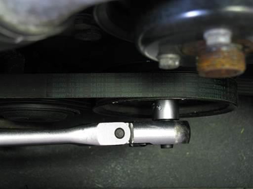
22 Assess tool needed for turning crankshaft. Inspect crankshaft pulley turning bolt(s) (mirror). If 4 torx bolts are found use special torx socket. If hex bolt fond use 32mm socket.
23


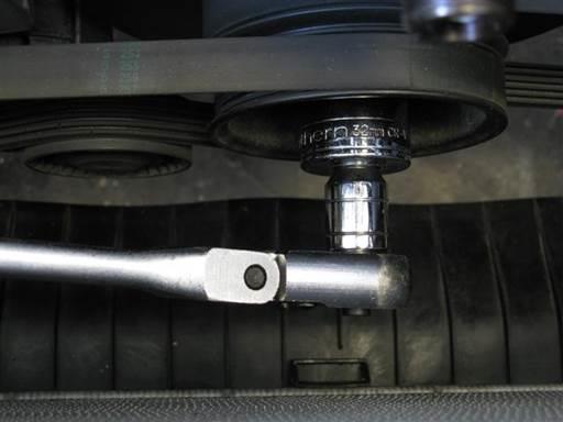
24 If manual transmission, place transmission in neutral. This allows turning of crankshaft. Turn crankshaft pulley clockwise until cylinder 1 intake and exhaust cams point to each other at ~45 degree angle (crankshaft turning socket 1/2" / 1/2 long-arm ratchet & short extension). Note: Turning crankshaft counter clockwise is acceptable.
.")
25 Inspect TDC (top dead center) timing marks on engine timing cover and crankshaft harmonic balancer at ~11 o clock position (mirror). Adjust crankshaft pulley to align TDC timing marks (crankshaft turning socket 1/2" / 1/2 long-arm ratchet & short extension). Note: Align pointer on timing cover bracket with 1 mark on harmonic balancer. Note: Precise alignment is not necessary. Removal of vanos solenoid Vanos solenoid removal relieves vanos hydraulics and allows manipulation of vanos and engine timing without need for air compressor and expensive electrical switches. This method is also easier to perform, clearer to understand, and less problematic.


26 Remove vanos solenoid electrical cable connector at vanos bottom left. Press in connector side clips and pull/pry off connector (tack lifter). If present, pull off and discard cable strap. Cover lower radiator hose to protect belts from oil leakage (towels).
.")
27 If installing vanos seals repair kit or rebuilt vanos solenoid coil pack, slightly loosen vanos oil pressure restrictor (22mm open wrench). Note: Pressure restrictor work will be performed at bench. Loosening is easier to perform while solenoid is mounted. Remove vanos solenoid 5 mounting bolts; 3 upper and 2 lower (5mm hex bit socket 3/8 / 3/8 ratchet & extension). Loosen bolts evenly and support solenoid as it drops from vanos.


28 Remove solenoid with sealing plate from engine bay. Retarding of camshaft timing Maintain cover over lower radiator hose during following camshaft adjustment as oil will leak from vanos bottom (towels).
 on exhaust camshaft hex at front of camshaft.")

29 Fully retard exhaust camshaft timing. Place open wrench (24mm combo wrench) on exhaust camshaft hex at front of camshaft. Rotate exhaust camshaft counter clockwise to adjustment end position. If camshaft resistant to rotation rock camshaft back and forth to release seize. Note: Camshaft rotation is most effective when standing at exhaust side of car. Note: Splined shaft can be seen protruding from sprocket hub front when camshaft

30 is at adjustment end position. Note: Camshaft adjustment causes full camshaft timing retard. This causes splined shaft and vanos piston forward positioning. This facilitates access for disconnecting splined shaft from vanos piston in coming step. Fully retard intake camshaft timing.

31 Place open wrench (24mm combo wrench) on intake camshaft hex at front of camshaft. Rotate intake camshaft counter clockwise to adjustment end position. If camshaft resistant to rotation rock camshaft back and forth to release seize. Note: Camshaft rotation is most effective when standing at exhaust side of car. Note: Splined shaft can be seen protruding from sprocket hub front when camshaft is at adjustment end position. Note: Camshaft adjustment causes full camshaft timing retard. This causes splined shaft and vanos piston forward positioning. This facilitates access for disconnecting splined shaft from vanos piston in coming step. When intake and exhaust camshafts are fully retarded holes in the camshafts between cylinder 2 & 3 will point up perpendicularly to engine head. Remove covers from lower radiator hose (towels). Wipe clean bottom of vanos (towels). Removal of vanos


32 Remove camshaft chain guide. Remove chain guide 2 mounting bolts (5mm hex bit socket 3/8 / 3/8 ratchet). Remove chain guide. Cover cavities between vanos and sprockets to keep bolts from falling down in next step (towels).
.")
33 Remove vanos bracket. Remove vanos bracket 2 mounting bolts (10mm socket 3/8 / 3/8 ratchet & extension). Remove vanos bracket. Note vanos bracket mounting orientation. Remove covers (towels).


34 Remove oil accumulator pipe from vanos. Remove oil pipe mounting banjo bolt (14mm socket 3/8 / 3/8 ratchet). Discard crush washer at each side of pipe fitting. Locate oil accumulator pipe bracket mounting bolt under radiator lower hose (mirror).

.")
35 Remove oil accumulator pipe bracket mounting bolt (10mm socket 3/8 / 3/8 ratchet & extension). Move oil accumulator pipe to rear.
.")

36 Cover lower radiator hose to protect belts from oil leakage in next steps (towels). Remove vanos 5 mounting bolts; 2 top corner and 3 lower (10mm socket & 5mm hex bit socket 3/8 / 3/8 ratchet & extension).
.")
.")
37 Pry vanos forward off engine head. Pry between vanos and engine head at vanos top right and left ends (medium puttyknife). Insert blade between vanos and engine head and hit blade to press in and separate vanos from engine head (medium putty-knife & hand). Pry vanos evenly rotating between each side until vanos releases and separates from engine head.

38 Pull vanos forward as far as possible. Note: Once vanos comes off engine head, vanos will be suspended on intake and exhaust splined shafts. Caution: Once vanos is pulled off engine head it should not be remounted without aligning exhaust side vanos oil pump and camshaft oil pump driver. Install vanos solenoid long mounting bolts at vanos top right and left mounting holes to support vanos on engine head (picture). Insert bolts into head with only a few turns (hand). Disconnecting of vanos pistons from splined shaft studs

39 Cover cavities below sprockets to keep tools from falling into cavities (towels). Rotate vanos intake piston to allow tool access to splined shaft stud flats (10mm open wrench).
40 Disconnect vanos intake piston from intake splined shaft stud. Counter hold splined shaft stud and unscrew vanos piston; left hand thread (7mm open wrench, 10mm open wrench). Note: Piston and shaft stud are left hand thread, thus unscrew by turning piston tool (10mm open wrench) from left to right (clockwise) (car front orientation). Note: As needed, rotate piston tool (10mm open wrench) at every turn to facilitate tool access.
41 Rotate vanos exhaust piston to allow tool access to splined shaft stud flats (10mm open wrench).
 from left to right (clockwise) (car front orientation).")
42 Disconnect vanos exhaust piston from exhaust splined shaft stud. Counter hold splined shaft stud and unscrew vanos piston; left hand thread (7mm open wrench, 10mm open wrench). Note: Piston and shaft stud are left hand thread, thus unscrew by turning piston tool (10mm open wrench) from left to right (clockwise) (car front orientation). Note: As needed, rotate piston tool (10mm open wrench) at every turn to facilitate tool access. Remove sprocket cavity covers.


43 Unscrew solenoid long bolts at vanos top corners from engine head while supporting vanos. Remove vanos and take to work bench. Note rotational position of vanos oil pump holes. This position is necessary for reinstalling vanos and matting it with oil pump driver tabs.


44 Replacement of vanos oil pump disk Perform following work on table to prevent parts from falling and being damaged. Remove oil pump retaining ring. Compress ring at end holes and remove ring form vanos (retaining ring pliers).


45 Remove oil pump retaining washer. Pry out washer from inner perimeter and pull out (90 degree pick).


46 Inspect mounting position of pump disk outer bearing ring to outer radial bearing. Note bearing ring protrudes out slightly higher than bearing ring. Install clear plastic bag over vanos oil pump side.


47 Turn vanos down and hit end of vanos on table to dislodge oil pump disk from vanos.

, remove bearing ring from vanos (90")
48 Remove plastic bag from vanos with oil pump disk, caps and springs, and bearing ring. Note: If bearing ring still in vanos (picture), remove bearing ring from vanos (90 degree pick).
.")

49 Remove spring pads from oil pump 4 side holes. Insert tool in pad center hole and pry out pad (strait pick). Insert old oil pump disk on exhaust sprocket hub and rotate back and forth to assess amount of play between oil pump holes and exhaust hub tabs. Perform same with new oil pump disk. Be sure to use newly drilled and marked holes.


50 New disk holes significantly reduce hole to tab play and thus prevent hitting and tab breaking. Clean oil pump components and verify inventory (brake cleaner & towels). Components include: retaining ring, retaining washer, bearing ring, 4 x cap, 4 x spring, 4 x spring pad. Install 4 spring pads in oil pump side holes.

51 Insert tool in pad protruding nipple center hole and insert pad to bottom of side hole (strait pick). Caution: Spring pads must be installed in correct orientation. Pad protruding nipple must point out. Install 4 springs in oil pump side holes. Insert spring on side hole.

52 Install 4 caps on oil pump side hole springs. Install cap on spring.
.")

53 Install pump disk with caps and springs in bearing ring. Slightly insert 4 caps and springs into oil pump disk side holes with 4 fingers (picture). Lift disk with caps slightly inserted and place over bearing ring. Press in all caps and insert disk with caps inside bearing ring. Once caps inserted into ring, hold disk down and pull ring up slightly to position
.")

54 caps at ring center groove. Lightly lubricate pump disk center bushing (assembly oil). Clean vanos oil pump housing (brake cleaner & towels). Lightly lubricate vanos center shaft side and outer radial bearing to ease pump installation (assembly oil). Initially install oil pump disk on oil pump shaft.

.")
55 Tilt pump side to side as needed to insert onto shaft. Only initially insert and seat disk onto shaft. Do not insert further. Press bearing ring to right side to align and insert into radial bearing (fingers). Once bearing ring aligns with radial bearing slightly press down bearing ring to insert into radial bearing.
. Once fully pressed down and released, bearing ring will come back up slightly to align with disk caps.")
56 Press down on bearing ring to fully insert into radial bearing. Oil pump disk will slide down center shaft as bearing ring lowers. Press down on bearing ring at multiple locations to insure full insertion (90 degree pick). Once fully pressed down and released, bearing ring will come back up slightly to align with disk caps. Check position of bearing ring top relative to radial bearing top along perimeter to verify full bearing ring insertion (finger). Note bearing ring will protrude out slightly further than radial bearing. Lightly lubricate each pump cap (assembly oil). Turn pump disk and lubricate each cap as it becomes exposed on right side. Turn pump disk and verify smooth operation. Adjust and lubricate components as necessary.


57 Install retaining washer in oil pump housing. Initially insert retaining ring in oil pump housing.
.")

58 Compress retaining ring and insert into oil pump housing ring groove (retaining ring pliers). Visually verify retaining ring is inserted into housing ring groove. Turn pump disk and verify smooth operation. Note: Oil pump rotates counterclockwise in normal operation. If rotated in this
59 direction air can be heard compressed and released. In engine operation this will be oil compressed and released. Function of oil pump is to compress oil to high pressure. It is then regulated down to 100 bar (1,450 psi). Replacement of vanos sealing plate rubber rings Clean vanos sealing plate (brake cleaner & towels).

60 Cut rubber rings from sealing plate (razor knife). Make radial cut from rubber ring inner diameter to sealing plate hole perimeter, then cut along sealing plate hole perimeter. Note: Cutting motion facilitates cutting. Once rubber ring is removed cut out remaining rubber at sealing plate hole perimeter. Note: Cutting some metal from sealing plate is normal and acceptable. Note: It is not necessary to remove all rubber from hole perimeter.
 in holes and thus will maintain their mounted position.")
61 Clean sealing plate rubber ring hole perimeter surfaces (brake cleaner & towels). Insert new O-rings into corresponding size sealing plate rubber ring holes. Note: O-rings fit with slight interference (larger) in holes and thus will maintain their mounted position. Note: O-rings will adjust position and fit correctly once sealing plate is installed. Installation of vanos seals

62 During following seals installation procedure, great care should be taken to not drop and damage vanos components. Perform work over table, so if part is dropped it will fall to table top. Installation of vanos intake seals Remove vanos intake cylinder cover. Remove cover 3 mounting bolts (5mm hex bit socket 3/8 / 3/8 ratchet).
.")

63 Remove intake cylinder cover. Pry cover at multiple locations to evenly remove cover (small putty-knife). As necessary, strike blade between cover and vanos body to initially break seize. Note: Orient blade with edge ramp side to vanos body. This orientation is more effective. Note: Cover resistance is due to cover sealing O-ring.
. Note: Rocking of blade while pressing helps create cutting motion.")
64 Remove intake piston from intake cylinder. Press piston from vanos inboard side to remove piston from vanos outboard side (1/4 socket extension). Cut cross section of intake piston end seal Teflon ring (razor knife). Note: Rocking of blade while pressing helps create cutting motion. Rotate blade in seal after cutting to note any remaining uncut seal (razor knife).
65 Remove cut Teflon ring from piston grove. Cut cross section of intake piston end seal O-ring (razor knife). Note: Rocking of blade while pressing helps create cutting motion. Rotate blade in seal after cutting to note any remaining uncut seal (razor knife). Remove cut O-ring from piston grove.
66 When seal removal is complete, piston seal groove will have exposed metal with no seals. Clean intake piston (brake cleaner & towels).
67 Insert intake piston end seal new O-ring in piston seal groove at one end and stretch other end over piston and drop into seal groove (fingers). Center O-ring in seal groove (strait pick).
.")
68 Insert intake piston end seal new Teflon ring in piston seal groove at one end and stretch other end over piston and drop into seal groove (fingers). Stretch Teflon ring at multiple location along Teflon ring before final stretch over piston and into groove (fingers).

69 Insert intake piston large end into intake cylinder. Lightly lubricate cylinder entry inner wall and piston Teflon ring (assembly oil). Wiggle piston and press strait into cylinder. Verify Teflon ring is inserting into cylinder at all perimeter locations. Reposition piston and reattempt insertion to facilitate Teflon ring full perimeter insertion. Once all Teflon ring perimeter inserts into cylinder, wiggle piston and press strait into cylinder to fully insert Teflon ring into cylinder. Note: Cylinder entry has chamfer which allows for stretched Teflon ring to be collected and inserted into cylinder.
 close to original size.")
70 Maintain piston in cylinder for 1 minute then remove. This period allows Teflon ring to be compressed (resized) close to original size. Remove piston from cylinder. Note Teflon ring has decreased in diameter.

71 Note intake rod seal on intake cylinder just inside cylinder inboard side. Note: Picture is of different vanos and shows burnt sludge buildup.


72 Pry out intake rod seal Teflon ring from intake cylinder seal groove. Pry Teflon ring from front to rear to dislodge from seal cavity, then pull Teflon ring out of cylinder (90 degree pick).
.")
73 Pry out intake rod seal O-ring from intake cylinder seal groove. Pry O-ring from rear to front to dislodge from seal cavity, then pull O-ring out of cylinder (90 degree pick). Crimp and hold intake rod seal new O-ring at approximate middle and hold (medium nose pliers). Note: Attempt to hold O-ring without allowing it to twist, as it needs to be strait for insertion in next step.


74 Insert intake rod seal new O-ring into cylinder seal groove bottom (picture). Then press down on O-ring and insert O-ring top into seal groove top. Release O-ring holding tool and O-ring will insert into seal groove. Press against O-ring remaining protruding section to fully insert into seal groove (medium nose pliers).

 (medium nose pliers).")
75 Press Intake rod seal new Teflon ring side into middle of Teflon ring and hold at crimped section (picture) (medium nose pliers).
.")
76 Insert intake rod seal new Teflon ring into cylinder seal groove bottom (picture). Release Teflon ring from holding tool and Teflon ring will insert into seal groove. Slowly press against Teflon ring remaining protruding section to fully insert into seal groove (medium nose pliers). Smooth Teflon ring by pressing along bent section from side to side (medium nose pliers side).
.")
 close to original size.")
77 Insert intake piston small end into intake cylinder inboard side. Lightly lubricate piston and cylinder rod seal Teflon ring (assembly oil). Wiggle piston and press strait into cylinder. Maintain piston in cylinder for 1 minute then remove. This period allows Teflon ring to be rebound (resized) close to original size. Remove piston from cylinder. Note Teflon ring has returned to original shape.
. Remove intake cylinder cover sealing O-ring.")
78 Insert intake piston small end first into intake cylinder outboard side and press piston fully into cylinder. Clean vanos intake cylinder outboard side cover mating surfaces and cover mounting bolts (brake cleaner & towels). Remove intake cylinder cover sealing O-ring. Pry O-ring from cover groove and remove from cover (90 degree pick).
79 Clean intake cylinder cover (brake cleaner & towels). Install new O-ring on intake cylinder cover. Insert O-ring in cover groove on one end and stretch other end over cover and drop into groove (fingers). Lightly lubricate O-ring to ease cover installation (assembly oil).
. Tighten bolts evenly to draw cover evenly to vanos body.")
80 Install intake cylinder cover on vanos. Orient cover to align cover holes with vanos holes. Cover is asymmetric and only one orientation aligns. Install intake cylinder cover 3 mounting bolts (5mm hex bit socket 3/8 / 3/8 ratchet). Tighten bolts evenly to draw cover evenly to vanos body. Fully tighten, 10 Nm (7 ft-lb) (5mm hex bit socket 3/8 / 3/8 torque wrench). Note: Tighten bolts evenly in multiple passes. Verify one pass with all bolts fully tightened. Installation of vanos exhaust seals

81 Remove vanos exhaust cylinder cover. Remove cover 3 mounting bolts (5mm hex bit socket 3/8 / 3/8 ratchet).
.")

82 Remove exhaust cylinder cover. Pry cover at multiple locations to evenly remove cover (small putty-knife). As necessary, strike blade between cover and vanos body to initially break seize. Note: Orient blade with edge ramp side to vanos body. This orientation is more effective. Note: Cover resistance is due to cover sealing O-ring. Remove exhaust piston from exhaust cylinder.
83 Press piston from vanos inboard side to remove piston from vanos outboard side (1/4 socket extension). Cut cross section of exhaust piston middle seal Teflon ring (razor knife). Note: Rocking of blade while pressing helps create cutting motion. Rotate blade in seal after cutting to note any remaining uncut seal (razor knife). Remove cut Teflon ring from piston grove.
. Remove cut O-ring from piston grove. Cut cross section of exhaust piston end seal Teflon ring (razor knife).")
84 Cut cross section of exhaust piston middle seal O-ring (razor knife). Note: Rocking of blade while pressing helps create cutting motion. Rotate blade in seal after cutting to note any remaining uncut seal (razor knife). Remove cut O-ring from piston grove. Cut cross section of exhaust piston end seal Teflon ring (razor knife). Note: Rocking of blade while pressing helps create cutting motion.
85 Rotate blade in seal after cutting to note any remaining uncut seal (razor knife). Remove cut Teflon ring from piston grove. Cut cross section of exhaust piston end seal O-ring (razor knife). Note: Rocking of blade while pressing helps create cutting motion. Rotate blade in seal after cutting to note any remaining uncut seal (razor knife). Remove cut O-ring from piston grove.


86 When seals removal is complete, piston seal grooves will have exposed metal with no seals. Clean exhaust piston (brake cleaner & towels).
. Center O-ring in seal groove (strait pick).")
 (picture).")
87 Mount exhaust piston middle seal O-ring onto exhaust piston small end and roll O- ring along piston and drop into seal groove (fingers). Center O-ring in seal groove (strait pick). Mount exhaust piston middle seal Teflon ring onto exhaust piston small end. Insert pick tool between Teflon ring and piston (90 degree pick) (picture). Leverage pick tool against piston and tilt pick tool to stretch out Teflon ring (90 degree pick).
.")
88 Perform Teflon ring stretching at multiple locations along Teflon ring until Teflon ring notably stretches. Note: Teflon ring needs to stretch sufficiently to slide over piston larger diameter. Place exhaust piston vertically with large end down. Press down on Teflon ring from top end to press Teflon ring onto piston larger diameter (fingers/nails). Move Teflon ring evenly along piston (picture). Note: If Teflon ring difficult to press down repeat previous Teflon ring stretching step.
89 Slide Teflon ring down exhaust piston to seal groove rim (fingers/nails) (picture).
90 Press down on Teflon ring from top end to press Teflon ring onto piston seal groove rim and drop Teflon ring into seal groove (fingers/nails). Move Teflon ring evenly along piston (picture).
. Center O-ring in seal groove (strait pick).")
91 Insert exhaust piston end seal O-ring in piston seal groove at one end and stretch other end over piston and drop into seal groove (fingers). Center O-ring in seal groove (strait pick).
.")
92 Insert exhaust piston end seal Teflon ring in piston seal groove at one end and stretch other end over piston and drop into seal groove (fingers). Stretch Teflon ring at multiple location along Teflon ring before final stretch over piston and into groove (fingers).

93 Insert exhaust piston large end into exhaust cylinder outboard side. Lightly lubricate cylinder entry inner wall and piston Teflon ring (assembly oil). Wiggle piston and press strait into cylinder. Verify Teflon ring is inserting into cylinder at all perimeter locations. Reposition piston and reattempt insertion to facilitate Teflon ring full perimeter insertion. Once all Teflon ring perimeter inserts into cylinder, wiggle piston and press strait into cylinder to fully insert Teflon ring into cylinder. Note: Cylinder entry has chamfer which allows for stretched Teflon ring to be collected and inserted into cylinder.
 close to original size.")

94 Maintain piston in cylinder for 1 minute then remove. This period allows Teflon ring to be compressed (resized) close to original size. Remove piston from cylinder. Note Teflon ring has decreased in diameter. Place small hose clamp around exhaust piston middle seal Teflon ring (small hose clamp). Tighten clamp until it seats on piston (Philips).
. Note Teflon ring has compressed. Note: Clamp will leave slight crease on Teflon surface.")
95 Note: Only lightly tighten clamp on piston. Note: Mounting clamp on piston middle seal Teflon ring will compress Teflon ring to close to original size and allow piston insertion in next step. Remove hose clamp from exhaust piston (Philips). Note Teflon ring has compressed. Note: Clamp will leave slight crease on Teflon surface. This crease will rectify once Teflon ring is heated in engine.


96 Lightly lubricate exhaust piston middle seal Teflon ring (assembly oil). Insert exhaust piston small end into exhaust cylinder outboard side.
.")

97 Place flat object on exhaust piston end (small putty-knife handle). Press in on piston with moderate pressure until piston inserts into cylinder (picture). Note: During this step piston middle seal Teflon ring is being inserted into exhaust smaller cylinder. Cylinder entry has chamfer which will allow for stretched Teflon ring to be collected and inserted into cylinder. Maintain piston in cylinder for 1 minute then remove. This period allows Teflon ring to be compressed (resized) close to original size.
98 Remove piston from cylinder by pressing piston from inboard side. Note Teflon ring has decreased in diameter. Insert exhaust piston small end first into exhaust cylinder outboard side and press piston fully into cylinder. Clean vanos exhaust cylinder outboard side cover mating surfaces and cover mounting bolts (brake cleaner & towels).
99 Remove exhaust cylinder cover sealing O-ring. Pry O-ring from cover groove and remove from cover (90 degree pick). Clean exhaust cylinder cover (brake cleaner & towels). Install new O-ring on exhaust cylinder cover. Insert O-ring in cover groove on one end and stretch other end over cover and drop
. Tighten bolts evenly to draw cover evenly to vanos body.")
100 into groove (fingers). Lightly lubricate O-ring to ease cover installation (assembly oil). Install exhaust cylinder cover on vanos. Orient cover to align cover holes with vanos holes. Cover is asymmetric and only one orientation aligns. Install exhaust cover 3 mounting bolts (5mm hex bit socket 3/8 / 3/8 ratchet). Tighten bolts evenly to draw cover evenly to vanos body. Fully tighten, 10 Nm (7 ft-lb) (5mm hex bit socket 3/8 / 3/8 torque wrench). Note: Tighten bolts evenly in multiple passes. Verify one pass with all bolts fully tightened.


101 Remove vanos oil flow regulator from vanos. Rotate regulator to break seize then pull regulator from vanos. Remove regulator small O-ring. Pry O-ring from regulator groove and remove from regulator (90 degree pick).
. Install new small O-ring on regulator.")
102 Remove regulator large O-ring. Pry O-ring from regulator groove and remove from regulator (90 degree pick). Clean oil flow regulator (brake cleaner & towels). Install new small O-ring on regulator. Insert O-ring in regulator groove on one end and stretch other end over regulator and drop into groove (fingers).

103 Lightly lubricate O-ring to ease vanos installation (assembly oil). Note: Oil regulator small O-ring is similar in size to vanos solenoid oil pressure restrictor small O-ring. Oil regulator O-ring is slightly thicker in cross section than oil pressure restrictor small O-ring. Install new large O-ring on regulator. Insert O-ring in regulator groove on one end and stretch other end over regulator and drop into groove (fingers). Lightly lubricate O-ring to ease regulator installation (assembly oil).

104 Orient regulator with overflow holes to sides of vanos (picture) and fully insert regulator into vanos. Remaining two O-rings in seals kit are for oil pressure restrictor and their installation is covered in the next solenoid section. Replacement of solenoid coil pack, pressure restrictor O-rings, and oil filter
.")
105 Remove coil pack 4 mounting bolts (E-5 torx or 4mm socket 1/4 / 1/4" ratchet). Pull off coil pack (black) from valve body (silver).
. Drain and discard oil from valve body.")

106 Unscrew oil pressure restrictor from valve body (hand). Drain and discard oil from valve body. Cleaning of solenoid valves Spray cleaner into all valve body available holes to clear out oil (brake cleaner).

107 Mount magnet on each valve shaft of valve body to open valve, then spray cleaner in corresponding valve small hole on opposite side of valve body (brake cleaner). Continue to spray cleaner into valve hole until cleaner runs clean from valve body. Perform valve opening and cleaning process for 4 valves. Once valves cleaned, each valve internal piston should be heard easily moving and clicking when magnet is applied on and off valve shaft.
. Note: Rocking of blade while pressing helps create cutting motion.")
108 Pull off oil filter from pressure restrictor (pliers). Note: Oil filter replacement is not a requirement. Oil filter can be spray cleaned (brake cleaner). Cut cross section of small O-ring on pressure restrictor (razor knife). Note: Rocking of blade while pressing helps create cutting motion. Note: Take care to not cut or damage adjacent plastic washer. Plastic washer
. Install new large O-ring on pressure restrictor.")
109 already has cross section cut which is needed for installation. Remove cut O-ring from pressure restrictor. Remove large O-ring from pressure restrictor (90 degree pick). Clean pressure restrictor (brake cleaner & towels). Install new large O-ring on pressure restrictor. Roll O-ring onto pressure restrictor till O-ring drops into base groove.
.")
110 Install small O-ring on pressure restrictor. Roll O-ring onto pressure restrictor till O-ring drops into groove. Install new oil filter on pressure restrictor. Press filter small hole end onto pressure restrictor end stud. Screw pressure restrictor into valve body (hand). Note: Pressure restrictor will be tightened once solenoid is mounted on vanos.
 (E-5 torx or 4mm socket 1/4 w/ 3/8 to 1/4 socket adapter / 3/8 torque wrench).")
111 Mount new coil pack on valve body. Align coil pack holes with valve body studs and mount. Install coil pack 4 mounting bolts (E-5 torx or 4mm socket 1/4 / 1/4 ratchet). Tighten bolts evenly in multiple passes. Fully tighten, 4 Nm (3 ft-lb) (E-5 torx or 4mm socket 1/4 w/ 3/8 to 1/4 socket adapter / 3/8 torque wrench). Note: Bolts can be tightened lightly by feel. Do not over tighten.
112 Cleaning of parts Note: When cleaning parts, spray cleaning compound on towel then wipe component with towel. Components can also be placed in a small container and sprayed with cleaning compound then individually wiped with towel. Clean all mounting bolts, nuts, washers (brake cleaner & towels). Clean vanos matting surfaces; solenoid (both vanos and solenoid), head gasket (brake cleaner & towels). Clean head matting surfaces; sparkplug well, top perimeter and rear half-moons, front vanos gasket (brake cleaner & towels). Clean coil harness ground wire (brake cleaner & towels). Clean coils mounting contact surfaces (at coils) (brake cleaner & towels). Clean valve cover gaskets (brake cleaner & towels). Note: S54 valve cover gaskets and bolt grommets are made of Viton and thus can withstand brake cleaner. Brake cleaner will allow for removing oil from gaskets. Clean valve cover mating surfaces; inner gasket, bolt access holes, all studs, exhaust side ground wire hole, exhaust side oil drain hole (brake cleaner & towels). Perform rattle procedure If performing rattle procedure, do so at this time. S54 Vanos Rattle Procedure Installation of vanos


113 Rotate vanos oil pump to approximate position found when vanos was first removed. This position will locate oil pump holes close to oil pump driver tabs position on exhaust sprocket hub. This facilitates easier alignment and installation. Note: Pump disk new smaller holes to be used are marked black. If vanos top corner alignment dowels remained on vanos place vanos gasket on vanos.
.")
114 Place gasket on vanos with gasket ridge to vanos. Gasket two lower tabs will point to vanos (picture). If vanos top corner alignment dowels remained on engine head place vanos gasket on engine head. Place gasket on head with gasket ridge to vanos (front). Gasket two lower tabs will point to vanos (front) (picture).


115 Mount vanos onto engine head with solenoid 2 long bolts at vanos top corners. Screw solenoid long bolts into engine head just a few turns. Connecting of vanos pistons to splined shaft studs Cover cavities below sprockets to keep tools from falling down (towels).
.")
116 Rotate intake splined shaft stud to facilitate tool access to stud flats (fingers). Mount splined shaft stud tool (7mm open wrench). Install pliers on vanos intake piston hex (medium nose pliers). Lift up vanos and pull vanos intake piston onto splined shaft stud (medium nose pliers). While pressing piston onto splined shaft, counter hold splined shaft stud and thread piston onto splined shaft stud one rotation; left hand thread (medium nose pliers /
117 7mm open wrench). Note: Piston and shaft stud are left hand thread, thus screw by turning piston tool (medium nose pliers) from right to left (counter clockwise) (car front orientation). Thread intake piston onto splined shaft stud; left hand thread (10mm open wrench / 7mm open wrench). Note: Piston and shaft stud are left hand thread, thus screw by turning piston tool
. Note: Due to left hand thread, it is not necessary to over tighten joint.")
118 (10mm open wrench) from right to left (counter clockwise) (car front orientation). Note: As needed, rotate piston tool (10mm open wrench) at every turn to facilitate tool access. Lightly tighten; left hand thread (10mm open wrench / 7mm open wrench). Note: Due to left hand thread, it is not necessary to over tighten joint. Rotate exhaust splined shaft stud to facilitate tool access to stud flats (fingers). Mount splined shaft stud tool (7mm open wrench).
.")
.")
119 Install pliers on vanos exhaust piston (medium nose pliers). Pull vanos exhaust piston onto splined shaft stud (medium nose pliers). While pressing piston onto splined shaft, counter hold splined shaft stud and thread piston onto splined shaft stud one rotation; left hand thread (medium nose pliers / 7mm open wrench). Note: Piston and shaft stud are left hand thread, thus screw by turning piston tool (medium nose pliers) from right to left (counter clockwise) (car front orientation).
 from right to left (counter clockwise) (car front orientation).")
120 Thread exhaust piston onto splined shaft stud; left hand thread (10mm open wrench / 7mm open wrench). Note: Piston and shaft stud are left hand thread, thus screw by turning piston tool (10mm open wrench) from right to left (counter clockwise) (car front orientation). Note: As needed, rotate piston tool (10mm open wrench) at every turn to facilitate tool access. Tighten; left hand thread (10mm open wrench / 7mm open wrench). Note: Due to left hand thread, it is not necessary to over tighten joint. Remove covers (towels).

121 Press vanos onto engine head until it stops or top corner alignment dowels are reached. Caution: Do not attempt to forcibly fully mount vanos to engine head. This can cause damage.

122 Inspect vanos oil pump side hole and exhaust sprocket hub driver side tab for alignment. Rotate vanos oil pump as needed to achieve alignment (fingers).

123 Press vanos onto engine head and verify driver tab insertion into oil pump hole. Realign vanos pump as need to facilitate tab insertion (fingers). Remove solenoid long bolts at vanos top corners. Align vanos dowels and mating holes and press on vanos to mate. Press on vanos and wiggle and fully mate with engine head.
 (10mm socket & 5mm hex bit socket 3/8 / 3/8 torque wrench & extension). Tighten bolts evenly in multiple passes.")
124 Install vanos 5 mounting bolts; 2 top corner hex head and 3 lower hex bit head (10mm socket & 5mm hex bit socket 3/8 / 3/8 ratchet & extension). Fully tighten, 10 Nm (7 ft-lb) (10mm socket & 5mm hex bit socket 3/8 / 3/8 torque wrench & extension). Tighten bolts evenly in multiple passes. Verify one pass with all bolts fully tightened.
.")
125 Reposition oil accumulator pipe to vanos. Align pipe lower bracket to mounting hole below radiator lower hose (mirror). Install oil accumulator pipe bracket mounting bolt (10mm socket 3/8 / 3/8 ratchet & extension). Note: Bolt is similar but shorter than vanos bracket two mounting bolts. Note: Initially install bolt by feel (hand).

.")
126 Fully tighten by feel (10mm socket 3/8 / 3/8 ratchet & extension). Do not over tighten. Install oil accumulator pipe at top of vanos. Install banjo bolt with new crush washer at both sides of pipe fitting (14mm socket 3/8 / 3/8 ratchet). Note: Banjo bolt is smaller of two available banjo bolts and correspondingly crush


127 washers are smaller of two sets of available crush washers. Note: Lift pipe fitting up to allow bolt to align and thread. Fully tighten, 13 Nm (9.5 ft-lb) (14mm socket 3/8 / 3/8 torque wrench). Install vanos bracket. Cover cavities between vanos and sprockets to keep bolts from falling down (towels) (not shown).


128 Position bracket in place. Note orientation of bracket. Install 2 bracket bolts at vanos (hand). Do not tighten bolts. Remove covers (towels). Install chain rail guide.
. Fully tighten vanos bracket and chain rail guide mounting bolts, 9 Nm (6.")
129 Align vanos bracket holes with camshaft bracket holes. Align chain rail guide bolt holes and vanos bracket bolt holes with camshaft bracket holes. Install chain rail guide 2 mounting bolts (5mm hex bit socket 3/8 ). Fully tighten vanos bracket and chain rail guide mounting bolts, 9 Nm (6.5 ft-lb) (5mm hex bit socket & 10mm socket 3/8 / 3/8 torque wrench). Tighten bolts evenly in multiple passes. Verify one pass with all bolts fully tightened. Installation of vanos solenoid Clean vanos solenoid matting surface (brake cleaner & towels). Place new sealing plate on vanos solenoid valve body (silver part). Align sealing plate notch with valve body notch. Verify sealing plate bolt holes align with valve body bolt holes, and sealing plate rubber rings align with valve body oil holes.

.")
130 Insert solenoid with sealing plate under vanos. Orient oil pressure restrictor to right. Align solenoid and sealing plate left front corner to vanos corner. Align solenoid and sealing plate bolt hole to vanos lower left bolt hole. Install solenoid lower left mounting bolt to hold solenoid (hand). Install solenoid 5 mounting bolts, 3 upper and 2 lower (5mm hex bit socket 3/8 / 3/8 ratchet & extension). Align solenoid and sealing plate to vanos to facilitate bolt insertion.
131 Fully tighten, 10 Nm (7 ft-lb) (5mm hex bit socket 3/8 / 3/8 torque wrench & extension). Tighten bolts evenly in multiple passes. Verify one pass with all bolts fully tightened. If vanos oil pressure restrictor previously loosened, fully tighten pressure restrictor (22mm open wrench) Note: Pressure restrictor is sealed with base O-ring thus restrictor only needs to be moderately tightened.

.")
132 Insert cable strap end into cable strap lock bracket. Reduce cable strap formed circle to size larger than vanos electrical cable connector. Orient cable strap with excess strip pointing front and up (picture). Insert cable strap over vanos electrical cable and solenoid electrical connector neck.


133 Install vanos electrical cable connector. Press in connector until clips snap into place. Tighten cable strap on electrical cable and solenoid electrical connector neck. Cut cable strap excess strip (cutters). Installation of valve cover


134 Apply thin layer of sealant at vanos and head matting junctions at top right and left of vanos (gasket sealant). Allow sealant to solidify for 2 minutes before mounting valve cover gasket.

135 Install valve cover perimeter gasket and sparkplug well gaskets on engine head. Note: There is no orientation to sparkplug well gaskets. Orient valve cover gasket with half-moons to rear and facing down. Verify perimeter gasket alignment pins at cyl 1 & 5 on each side of head and 2 at vanos top are fully aligned and inserted. Verify gasket rear half-moons straddle and insert onto head. Note: If gasket perimeter pins do not fully insert into head and vanos then gasket will not lay flat and will leak oil. Note: Valve cover gasket and sparkplug well gaskets are Viton and can be reused.

136 Install valve cover on engine head and vanos. Lift up rear connectors and cables and insert valve cover under them. Tilt cover left side up and insert cover right side under fuel injector electrical rail. Align valve cover with engine head and gaskets and lay valve cover on engine head. Adjust cover to align head studs to protrude at center of cover holes. Check, by feel, gasket rear half-moons are aligned and seated correctly on head and cover. Check gasket dowels at cyl 1 & 5 on each side of head and 2 at vanos top are fully inserted and gasket is laying fully flat at their location. Do not install valve cover bolts at this time.


137 Install oil drain hose at exhaust side of valve cover. Place O2 sensors connector bracket and coil harness rail at top of valve cover. Install banjo bolt with new crush washer at both sides of pipe fitting (hand). Note: Install one crush washer on banjo bolt. Place second crush washer on valve cover and slide down to bolt hole while inserting banjo bolt through hose fitting. Bolt will insert into crush washer once crush washer is lowered sufficiently on valve cover.
138 Fully tighten, 25 Nm (18.5 ft-lb) (17mm socket 3/8 / 3/8 torque wrench). Place O2 sensors connector bracket and coil harness rail to exhaust side of valve cover. Install valve cover 15 mounting bolts and studs w/ washers and rubber grommets; 2 front corner studs, 1 front center bolt, 6 bolts at each side (10mm socket & 10mm deep socket 3/8 / 3/8 ratchet & extension). Install 2 new stud grommets. Note: Stud grommets are Buna and do fail. Remainder of valve cover bolt grommets are Viton and can be reused. Tighten bolts/studs evenly working back and forth, assuring even pressure distribution on cover. Tighten until bolts/studs bottom out on head. Fully tighten, 8Nm (6 ft-lb) (10mm socket & 10mm deep socket 3/8 / 3/8 torque wrench & extension).


139 Install each coil into original sparkplug well. For each coil, orient coil tab to align with valve cover coil tab mating slot, insert coil boot into sparkplug well, and press coil onto sparkplug well until it snaps into place. Install coils electrical harness. Place coil harness rail on valve cover. Insert cable boot in valve cover slot at cyl 4.


140 For each coil, lift up on connector pivot lock, press in cable electrical connector, and push down on connector pivot lock. Install coil harness rail 2 mounting bolts (8mm socket 1/4" / 1/4" ratchet & extension).


141 Install O2 sensors connector bracket at top of valve cover. Insert bracket left front and rear holes onto cover studs at cyl 2 & 5. Orient rear cables as shown (picture). Press right front and rear clips into coil harness bracket slots until clips snap into place. Install coil harness ground strap with mounting bolt at valve cover exhaust side (13mm socket 3/8 / 3/8 ratchet).


142 Install components at valve cover rear. Install O2 sensor connectors, O2 sensors cable mounting clips, rubber block and cables mounting clip. Route all cable though valve cover cable slot (picture).

143 Install engine top cover. Remove oil fill cap. Lift up cables and hose and insert top cover into position. Align cover with 6 mounting studs and lay cover onto studs and valve cover. Adjust cables at valve cover left rear as needed to facilitate top cover installation. Install oil fill cap.

144 Install ventilation hose onto crankcase vent valve at cover rear top. Press on hose connector until it snaps into place. Install top cover 6 mounting caps (10mm socket 3/8 / 3/8 ratchet & extension).
. Fully tighten, 40 Nm, (29.5 ft-lb) (13mm socket 3/8 / 3/8 torque wrench).")
145 Installation of suspension cross brace If present, install suspension cross brace. Mount suspension cross brace onto studs at right and left strut towers. Install 2 mounting nuts at left and right end of suspension cross brace (13mm socket 3/8 / 3/8 medium-arm ratchet). Fully tighten, 40 Nm, (29.5 ft-lb) (13mm socket 3/8 / 3/8 torque wrench). Installation of fan & shroud E46 M3 fan & shroud installation Installation of cabin filter housing E46 M3 cabin filter housing installation Post repair procedures Allow gasket sealant to cure a minimum of one hour before driving car. Please provide feedback on vanos forum. Copyright 2013 Beisan Systems, LLC
Two seal rings will be installed in each piston groove, total of four rings installed in each piston.
 When seals removal is complete, piston grooves will have exposed metal with no seals. Wipe clean piston grooves (towel). Repeat seals removal for second piston. Note: Deteriorated O-rings will be flattened
6-cylinder Double Vanos Procedure (E46, E39)
") 6-cylinder Double Vanos Procedure (E46, E39) The following information is provided for reference purposes only and should be used at your own risk In no event shall Beisan Systems, LLC or its members be
6-cylinder Double Vanos Procedure (E46, E39) The following information is provided for reference purposes only and should be used at your own risk In no event shall Beisan Systems, LLC or its members be
DrVanos.com Stage II Installation Instructions. Tool rental is available with the purchase of a vanos kit *See website for more info*
 DrVanos.com Stage II Installation Instructions Special Tools Needed: Camshaft locking tool TDC Crank pin Sprocket turning tool Tool rental is available with the purchase of a vanos kit *See website for
 Special Tools Needed: DrVanos.com Stage I Installation Instructions Camshaft locking tool TDC Crank pin Sprocket turning tool Tool rental is available with the purchase of a vanos kit *See website for
Installation Manual TWM Performance Short Shifter Cobalt SS/SC, SS/TC, HHR SS, Ion Redline and Saab 9-3
 Page 1 Installation Manual TWM Performance Short Shifter Cobalt SS/SC, SS/TC, HHR SS, Ion Redline and Saab 9-3 Please Note: It is preferable to park on a flat surface, as you will have to engage and disengage
TIMING BELT/CHAIN AND SPROCKETS
 9-82 ENGINE 4.7L DN TIMING BELT / CHAIN COVER(S) (Continued) Fig. 130 Accessory Drive Belt Tensioner 1 - TENSIONER ASSEMBLY 2 - FASTENER TENSIONER TO FRONT COVER Fig. 132 Timing Chain Cover Fasteners (4)
WARNING: ALWAYS relieve fuel pressure before disconnecting any fuel related component. DO NOT allow fuel to contact engine or electrical components.
 4.0L V8 - VINS [K,U] Selected Block 1990 Lexus LS 400 For Lextreme Powertrain 2020 S. Hacienda Blvd. # D Hacienda Heights California 91745 Copyright 1998 Mitchell Repair Information Company, LLC Friday,
Installation Manual TWM Performance Kia Forte Short Shifter
 Installation Manual TWM Performance Kia Forte 2009+ Short Shifter Begin the installation by parking on a flat surface, as you will have to engage and disengage the hand brake and shift from gears to neutral.
M52tu-M54 VANOS Assembly & Timing Using G.A.S. Professional Cam Tool Kit
 Home BMW Solutions Porsche Solutions DIY Tech Engine Services Dyno Services Machining About Contact Store Tool Rental M52tu-M54 VANOS Assembly & Timing Using G.A.S. Professional Cam Tool Kit This procedure
E39 Rear Shocks Write-up
 E39 Rear Shocks Write-up The following information is provided for reference purposes only and should be used at your own risk In no event shall Beisan Systems, LLC or its members be liable for incidental,
Ford Focus Zetec SVT Timing Belt
 2000-2004 Ford Focus Zetec SVT Timing Belt Replacement This guide will show you how to replace the timing belt on the 2.0L DOHC Zetec with VCT on a 2002 Ford Focus SVT. This is an interference motor. Written
INSTALLATION INSTRUCTIONS
 PERFORMER RPM CAMSHAFT / LIFTERS / LUBE KIT For 343-401 c.i.d. AMC V8 Engines CATALOG # 7132 INSTALLATION INSTRUCTIONS PLEASE study these instructions carefully before beginning this installation. Most
BEW engine timing belt replacement procedure from MOGolf (as demonstrated on a 2004 Jetta).
.") BEW engine timing belt replacement procedure from MOGolf (as demonstrated on a 2004 Jetta). Based on the procedure published by Volkswagen, but modified for the "average" shadetree mechanic. Some special
BEW engine timing belt replacement procedure from MOGolf (as demonstrated on a 2004 Jetta). Based on the procedure published by Volkswagen, but modified for the "average" shadetree mechanic. Some special
2012 Kia Soul L4 2.0L
 2012 Kia Soul L4 2.0L Vehicle» Engine, Cooling and Exhaust» Engine» Timing Chain» Service and Repair» Repair Procedures» Part 1 Removal Engine removal is not required for this procedure. CAUTION: Use fender
Installation Instructions COMPETITION/PLUS SHIFTER Ford Mustang MT82 6-Speed Manual Transmission Catalog#
 Installation Instructions COMPETITION/PLUS SHIFTER 2015-2017 Ford Mustang MT82 6-Speed Manual Transmission Catalog# 3916037 Rev. 00 WORK SAFELY! For maximum safety, perform this installation on a clean,
GENERAL INSTRUCTIONS. PERFORMER-PLUS CAMSHAFT / LIFTERS / LUBE KIT MODEL: c.i.d. Chevrolet V8 Engines CATALOG #2117
 Page 1 PERFORMER-PLUS CAMSHAFT / LIFTERS / LUBE KIT MODEL: 283-400 c.i.d. Chevrolet V8 Engines GENERAL INSTRUCTIONS PLEASE study these instructions carefully before beginning this installation. Most installations
Page 1 of 25. Service and Repair REMOVAL SIZED FOR PRINT. Related Components
 Page 1 of 25 Service and Repair REMOVAL Related Components Page 2 of 25 1ZZ-FE Page 3 of 25 2ZZ-GE 1. REMOVE UPPER FRONT FENDER APRON SEAL AND UPPER RADIATOR SUPPORT SEAL 2. DRAIN ENGINE COOLANT 3. REMOVE
HURST COMP/PLUS SHIFTER 2015 Ford Mustang (Getrag MT82 six-speed manual transmission) Catalog # by Hurst Performance
 Catalog # by Hurst Performance") FORM 159 0205 07/15 HURST COMP/PLUS SHIFTER 2015 Ford Mustang (Getrag MT82 six-speed manual transmission) Catalog #391 0205 2015 by Hurst Performance Thank you for purchasing the Hurst Comp/Plus Shifter.
FORM 159 0205 07/15 HURST COMP/PLUS SHIFTER 2015 Ford Mustang (Getrag MT82 six-speed manual transmission) Catalog #391 0205 2015 by Hurst Performance Thank you for purchasing the Hurst Comp/Plus Shifter.
Installation Notes: #86000-R Race Series +3.5 L/T Kit
 159 North Maple St. Unit J, CORONA CA 92880 P. 951-737-9682 F. 951-737-9006 WWW.CHAOSFAB.COM Installation Notes: #86000-R Race Series +3.5 L/T Kit Factory manual is recommended for removal and re-installation
Installation Instructions
 Preparing your vehicle to install your brake system upgrade 1. Rack the vehicle. 2. If you don t have a rack, then you must take extra safety precautions. 3. Choose a firmly packed and level ground to
9/24/2017 Camshaft Timing Chain Removal and Installation Engine Mechanical 2002 Audi A6/S6/Quattro/Allroad MotoLogic
 2002 A6/S6/Quattro/Allroad The information in this article comes from a service manual containing information that applies to the following engine code: BAS. Section Info: Report a problem with this article
Remove four nuts, then the cooling fan assembly.
 The DOHC and SOHC engines both use the same Service and Repair procedure from Isuzu. Make note that the DOHC and SOHC engines both use a single gear for the camshaft but use different alignment marks.
BLACKBIRD INSTALLATION SUPPLEMENT
 BLACKBIRD INSTALLATION SUPPLEMENT FOR 2003-7 FORD 6.0 LITER DIESEL SINGLE ALTERNATOR F-350, F-450, F-550, EXCURSION VERSION 7-07 Parts Description Blackbird Wiring Manual Installation Supplement 6.0 Liter
PERFORMER-PLUS Camshaft/Lifters/Lube Kit #2177 MODEL: c.i.d. Chrysler V8, 1967 & later (Not for 1985 & later 318 V8 with roller lifters)
") PERFORMER-PLUS Camshaft/Lifters/Lube Kit #2177 MODEL: 318-360 c.i.d. Chrysler V8, 1967 & later (Not for 1985 & later 318 V8 with roller lifters) PLEASE study these instructions carefully before installing
PERFORMER-PLUS Camshaft/Lifters/Lube Kit #2177 MODEL: 318-360 c.i.d. Chrysler V8, 1967 & later (Not for 1985 & later 318 V8 with roller lifters) PLEASE study these instructions carefully before installing
PERFORMER RPM Camshaft/Lifters/Lube Kit CATALOG #7102 MODEL: c.i.d. Chevrolet V8, 1957 & later
 PERFORMER RPM Camshaft/Lifters/Lube Kit CATALOG #7102 MODEL: 262-400 c.i.d. Chevrolet V8, 1957 & later CAMSHAFT: Edelbrock Performer RPM camshafts are ground specifically for use with the corresponding
2010 Transit Connect Workshop Manual. 31. Remove the 3 bolts, thermostat housing and thermostat.
 31. Remove the 3 bolts, thermostat housing and thermostat. 32. Remove the 2 bolts, stud bolt and the A/C compressor. 33. Remove the bolt and the KS. 34. Remove the 8 bolts and the crankcase vent oil separator.
Installation Manual TWM Performance Short Shifter Subaru Forester up to 2005
 - 1 - Installation Manual TWM Performance Short Shifter Subaru Forester up to 2005 Please Note: It is preferable to park on a flat surface, as you will have to engage and disengage the hand brake and shift
Installation Manual TWM Performance Short Shift Kit Stage 1 and Stage 2 MazdaSpeed 6
 Page 1 Installation Manual TWM Performance Short Shift Kit Stage 1 and Stage 2 MazdaSpeed 6 Please Note: It is preferable to park on a flat surface, as you will have to engage and disengage the hand brake
PERFORMER RPM Camshaft/Lifters/Lube Kit CATALOG #7102 MODEL: c.i.d. Chevrolet V8, 1957 & later
 PERFORMER RPM Camshaft/Lifters/Lube Kit CATALOG #7102 MODEL: 262-400 c.i.d. Chevrolet V8, 1957 & later PLEASE study these instructions carefully before installing your new camshaft. If you have any questions
 Page 1 of 21 303-01C Engine 5.4L (3V) 2009 F-150 REMOVAL Procedure revision date: 03/26/2009 Cylinder Head Special Tool(s) 3 Jaw Puller 303-D121 or equivalent Compressor, Valve Spring 303-1039 Holding
DISASSEMBLY. Engine. Special Tool(s) Locking Tool, Camshaft Phaser Sprocket Special Tool(s)
 Locking Tool, Camshaft Phaser Sprocket Special Tool(s)") 303-01B-1 DISASSEMBLY Engine Special Tool(s) Remover, Crankshaft Rear Slinger 303-514 (T95P-6701-AH) Special Tool(s) 303-01B-1 Locking Tool, Camshaft Phaser Sprocket 303-1046 Remover, Crankshaft Rear Seal
303-01B-1 DISASSEMBLY Engine Special Tool(s) Remover, Crankshaft Rear Slinger 303-514 (T95P-6701-AH) Special Tool(s) 303-01B-1 Locking Tool, Camshaft Phaser Sprocket 303-1046 Remover, Crankshaft Rear Seal
1. Remove the crankshaft pulley, engine coolant pump pulley and drive belt. 2. Remove the timing belt cover.
 DISASSEMBLY 1. Remove the crankshaft pulley, engine coolant pump pulley and drive belt. 2. Remove the timing belt cover. 3. Turn the crankshaft clockwise and align the timing marks so as to bring the No.
PERFORMER-PLUS CAMSHAFT / LIFTERS / LUBE KIT CATALOG # 2103 MODEL: 400 c.i.d. Chevrolet V8 engines GENERAL INSTRUCTIONS
 PERFORMER-PLUS CAMSHAFT / LIFTERS / LUBE KIT CATALOG # 2103 MODEL: 400 c.i.d. Chevrolet V8 engines GENERAL INSTRUCTIONS Please study these instructions carefully before you remove your stock camshaft.
TIMING BELT/CHAIN AND SPROCKETS INSTALLATION
 DR ENGINE - 3.7L 9-81 TIMING BELT / CHAIN COVER(S) (Continued) INSTALLATION CAUTION:Donotuseoilbasedliquidstocleantiming cover or block surfaces. Use only rubbing alcohol, along with plastic or wooden
2005 Toyota Truck RAV4 2WD L4 2.4L (2AZ FE)
") 2005 Toyota Truck RAV4 2WD L4 2.4L (2AZ FE) Vehicle» Engine, Cooling and Exhaust» Engine» Timing Chain» Service and Repair TIMING CHAIN TIMING CHAIN http://alldatapro.com/alldata/pro~v440713400~c39519~r0~od~n/0/108596970/110859775/110859788/110859790/34853741/100411974/34853743/56492475
2005 Toyota Truck RAV4 2WD L4 2.4L (2AZ FE) Vehicle» Engine, Cooling and Exhaust» Engine» Timing Chain» Service and Repair TIMING CHAIN TIMING CHAIN http://alldatapro.com/alldata/pro~v440713400~c39519~r0~od~n/0/108596970/110859775/110859788/110859790/34853741/100411974/34853743/56492475
1992 Mitsubishi 3000GT VR-4
 TIMING BELT Removal (Diamante SOHC) 1. Remove left front and left side splash shields. Using engine hoist, lift engine just enough to remove weight from engine mounts. Remove drive belts. Remove A/C tensioner
INSTALLATION GUIDE CRF150R Manual Revision:
 REKLUSE MOTOR SPORTS The z-start Pro Clutch INSTALLATION GUIDE CRF150R 191-810 Manual Revision: 032508 2002 Rekluse Motor Sports Rekluse Motor Sports, Inc. 110 E. 43rd Street Boise, Idaho 83714 208-426-0659
The following tools will be required to perform this new service procedure outlined in this bulletin:
 The following new service information outlined in this bulletin will aid technicians in removal and installation of the cylinder head without the removal of the front engine cover. The new service procedure
N63TU Valve Stem Seal Tool Kit Part #: AGA-N63TU-VSK-K BMW Part #:
 N63TU Valve Stem Seal Tool Kit Part #: AGA-N63TU-VSK-K BMW Part #: 83 30 2 450 434 Problem: The vehicle has smoke from the tailpipe when starting or aggressively accelerating and decelerating the engine.
 Page 1 of 75 303-01D Engine - 5.2L 32V Ti-VCT 2016 Mustang Assembly Procedure revision date: 12/15/2016 Special Tool(s) / General Equipment Engine Base Part Number: 6L084 205-142 (T80T-4000-J) Installer,
Prerequisites: Shop Manual (recommended) pages 3-9 through 3-13.
 pages 3-9 through 3-13.") Prerequisites: Order your gaskets average about $25.00 bucks X 2 so $50.00 4NK-11193-00-00 Obtain a shim kit (Should have several 265 and 270s) (Some dealers will exchange) Obtain a Valve Bucket Tool YM-33961
Prerequisites: Order your gaskets average about $25.00 bucks X 2 so $50.00 4NK-11193-00-00 Obtain a shim kit (Should have several 265 and 270s) (Some dealers will exchange) Obtain a Valve Bucket Tool YM-33961
IN-VEHICLE SERVICE. Engine Components
 file://c:\tso\tsocache\vdtom_5368\svk~us~en~file=svk31a14.htm~gen~ref.htm Page 1 of 10 Section 03-01A: Engine, 2.3L I-4 IN-VEHICLE SERVICE 1997 Ranger Workshop Manual Engine Components The views shown
1996 Aerostar/Ranger/Explorer
 Page 1 of 11 Section 03-01B: Engine, 3.0L V-6 IN-VEHICLE SERVICE 1996 Aerostar and Ranger Vehicles Workshop Manual Water Pump SPECIAL SERVICE TOOL(S) REQUIRED Description Tool Number Fan Clutch Holding
List of parts needed below. Tools needed
 1 BMW 645 Coolant leak repair (Cap with Seal Repair and Expanding Coolant Pipe Installation w Pics) By Michael R. Brown (Estimated time to complete the job is 6-8 hrs) List of parts needed below. BMW PART
1995 Mitsubishi Montero LS. Ensure timing marks are aligned. Mark timing belt direction of rotation.
 TIMING BELT NOTE: Ensure timing marks are aligned. Mark timing belt direction of rotation. Removal 1. Disconnect negative battery cable. Drain engine coolant. Remove engine coolant reservoir tank, fan
Timing Chain - Renew ( )
") «Scorpio '95 Table of Contents» «Section 21: Engine» «Subsection 21-05: 2,9 V6 24V Cosworth Engine» «REMOVAL AND INSTALLATION» Timing Chain - Renew (21 314 0) Special Tools 21-140-01Adaptor for 21-140
«Scorpio '95 Table of Contents» «Section 21: Engine» «Subsection 21-05: 2,9 V6 24V Cosworth Engine» «REMOVAL AND INSTALLATION» Timing Chain - Renew (21 314 0) Special Tools 21-140-01Adaptor for 21-140
OIL COOLER KIT CHEVY CAMARO 2.0T PARTS LIST AND INSTALLATION GUIDE INSTALL DIFFICULTY DISCLAIMER CAUTION TOOLS NEEDED NOTE INSTALL PROCEDURE
 PARTS LIST AND PARTS INCLUDED 3PC APPLICATION-SPECIFIC MOUNTING BRACKETS 1PC HORN RELOCATION MOUNTING BRACKET 1PC 25-ROW OIL COOLER (SLEEK SILVER OR STEALTH BLACK) 1PC 4'4" STAINLESS STEEL BRAIDED HOSE
TORKER-PLUS Camshaft/Lifters/Lube Kit CATALOG #5002 MODEL: c.i.d. Chevrolet V8
 PLEASE study these instructions carefully before installing your new camshaft. If you have any questions or problems, do not hesitate to call our Technical Hotline at: 1-800-416-8628. CAMSHAFT: Edelbrock
Timing Belt: Service and Repair
 2000 Hyundai Sonata L4-2.4L Page 1 Timing Belt: Service and Repair REMOVAL 1. Remove the crankshaft pulley, engine coolant pump pulley and drive belt. 2. Remove the timing belt cover. 2000 Hyundai Sonata
Performer-Plus Camshaft/Lifters/Lube Kit Part #2182 For 351-Windsor Ford V8 Engines Installation Instructions
 Performer-Plus Camshaft/Lifters/Lube Kit For 351-Windsor Ford V8 Engines Installation Instructions PLEASE study these instructions carefully before installing your new camshaft. If you have any questions
1-3/4" or 1-7/8" headers Aftermarket/re-curved distributors
 TORKER-PLUS Camshaft/Lifters/Lube Kit #5062 for 1967 & later 396-454 c.i.d. Chevrolet (not for use in 1965-66 396 & 427 engines requiring grooved rear journal) PLEASE study these instructions carefully
Timing Chain Renew ( ) Renew. Section Title. Special Tools. Proprietary Tools Scraper Engine support bar
 Renew. Section Title. Special Tools. Proprietary Tools Scraper Engine support bar") Timing Chain Renew ( 34 0) Special Tools 40 400 40 Engine support bar 40 0 Adaptor for -40 40 03 Adaptor for -40 Proprietary Tools Scraper Workshop Equipment Transmission jack Materials Cable ties Sealer
Timing Chain Renew ( 34 0) Special Tools 40 400 40 Engine support bar 40 0 Adaptor for -40 40 03 Adaptor for -40 Proprietary Tools Scraper Workshop Equipment Transmission jack Materials Cable ties Sealer
Copper Sleeve, Unit Injector, Replacement
 Volvo Trucks North America Greensboro, NC USA This service bulletin replaces SB 237-46, Copper Sleeve, Unit Injector, Replacement dated 6.2007, publication no. PV776-20177417. DService Bulletin Trucks
Engine. Special Tool(s) Compressor, Piston Ring 303-D032 (D81L-6002-C) or equivalent. Compressor, Valve Spring (T93P-6565-AR)
 Compressor, Piston Ring 303-D032 (D81L-6002-C) or equivalent. Compressor, Valve Spring (T93P-6565-AR)") SECTION 303-01C: Engine 5.4L (4V) 2009 Mustang Workshop Manual ASSEMBLY Procedure revision date: 12/12/2008 Engine Special Tool(s) Compressor, Piston Ring 303-D032 (D81L-6002-C) or equivalent Compressor,
SECTION 303-01C: Engine 5.4L (4V) 2009 Mustang Workshop Manual ASSEMBLY Procedure revision date: 12/12/2008 Engine Special Tool(s) Compressor, Piston Ring 303-D032 (D81L-6002-C) or equivalent Compressor,
Installation Instructions HURST COMPETITION AND BILLET/PLUS SHIFTER Mustang w/5-speed Manual Transmission (GT only)
") Installation Instructions HURST COMPETITION AND BILLET/PLUS SHIFTER 2005-2010 Mustang w/5-speed Manual Transmission (GT only) Catalog# 3915201 WORK SAFELY! For maximum safety, perform this installation
Installation Instructions HURST COMPETITION AND BILLET/PLUS SHIFTER 2005-2010 Mustang w/5-speed Manual Transmission (GT only) Catalog# 3915201 WORK SAFELY! For maximum safety, perform this installation
BLACKBIRD INSTALLATION SUPPLEMENT
 BLACKBIRD INSTALLATION SUPPLEMENT FOR 2003-7 FORD 6.0 LITER DIESEL F-SERIES DUAL ALTERNATOR VERSION 10/07 Blackbird Installation Supplement for Ford 6.0. Liter Dual Alternator Parts included in the 6.0
HYDRAULICS. TX420 & & lower. Hydraulic Tandem Pump Removal. 4. Remove the LH side panel (Fig. 0388).
.") TX420 & 425 240000299 & lower 4. Remove the LH side panel (Fig. 0388). Hydraulic Tandem Pump Removal Note: Cleanliness is a key factor in a successful repair of any hydraulic system. Thoroughly clean all
TX420 & 425 240000299 & lower 4. Remove the LH side panel (Fig. 0388). Hydraulic Tandem Pump Removal Note: Cleanliness is a key factor in a successful repair of any hydraulic system. Thoroughly clean all
Performer RPM Camshaft/Lifters/Lube Kit CATALOG #7106 MODEL: c.i.d. Ford V8
 Performer RPM Camshaft/Lifters/Lube Kit MODEL: 352-428 c.i.d. Ford V8 PLEASE study these instructions carefully before installing your new camshaft. If you have any questions or problems, do not hesitate
PARTS TOOLS. Set Screw. Washer (2) Blue Bushing (2) Black Bushing (2) B&M Short Throw Shifter. Jam Nut Grease. Retaining Ring (2) Insert (2)
 Blue Bushing (2) Black Bushing (2) B&M Short Throw Shifter. Jam Nut Grease. Retaining Ring (2) Insert (2)") Installation Instructions SHORT THROW SHIFTER Fits: Porsche Boxter, Boxter S, 911, 996 Cayman & Cayman S models See Application Guide for specific year ranges and engine sizes Catalog # 45135 WORK SAFELY!
Installation Instructions SHORT THROW SHIFTER Fits: Porsche Boxter, Boxter S, 911, 996 Cayman & Cayman S models See Application Guide for specific year ranges and engine sizes Catalog # 45135 WORK SAFELY!
PERFORMER RPM Camshaft/Lifters/Lube Kit CATALOG #7112 MODEL: c.i.d. Oldsmobile V8, 1967 & later
 PERFORMER RPM Camshaft/Lifters/Lube Kit MODEL: 330-350-403 c.i.d. Oldsmobile V8, 1967 & later PLEASE study these instructions carefully before installing your new camshaft. If you have any questions or
<4D5> ENGINE Click on the applicable bookmark to selected the required model year
 ENGINE 11B-2 ENGINE General Information GENERAL INFORMATION 11100010339 Items 4D56 Total displacement m 2,477 Bore x Stroke mm 91.1 x 95.0 Compression ratio 21 Combustion chamber Camshaft
Installation Manual TWM Performance Short Shifter 2008 Mitsubishi Lancer
 Page 1 Installation Manual TWM Performance Short Shifter 2008 Mitsubishi Lancer Please Note: It is preferable to park on a flat surface, as you will have to engage and disengage the hand brake and shift
Engine Dismantle and Assemble ( )
") Engine Dismantle and Assemble ( 34 8) Special Tools 5 053 Slide hammer 47 Vibration damper remover 47 5053 00 Splined head socket, cylinder head bolts 87 Mounting stand with geared drive 00 059C Installer
Engine Dismantle and Assemble ( 34 8) Special Tools 5 053 Slide hammer 47 Vibration damper remover 47 5053 00 Splined head socket, cylinder head bolts 87 Mounting stand with geared drive 00 059C Installer
TIMING CHAIN COMPONENTS
 h Page 1 of 52 TIMING CHAIN COMPONENTS ht Page 2 of 52 Fig. 24: Displaying Timing Chain Components (1 Of 2) Page 3 of 52 Fig. 25: Displaying Timing Chain Components (2 Of 2) Page 4 of 52 REMOVAL NOTE:
Wheel Bearing Replacement Passat TDI
 Rear Bearing/hub assembly replacement This is a fairly straight forward process. Pictures are not necessary for most of this procedure for a person with skills to do this repair. Anyone who thinks they
REMOVAL. Cylinder Head. All cylinder heads. 1. Remove the engine. For additional information, refer to Engine in this section.
 303-01B-1 303-01B-1 REMOVAL Cylinder Head Material Item Specification Special Tool(s) Motorcraft Metal Surface Prep Modular Engine Lift Bracket ZC-31 303-F047 (014-00073) or equivalent Silicone Gasket
Ford Racing Performance Improvement Intake Manifold (96-04 GT) Time Necessary: Approximately 4 hours
 Time Necessary: Approximately 4 hours") Ford Racing Performance Improvement Intake Manifold (96-04 GT) Time Necessary: Approximately 4 hours Tools Required: Ratchet and socket set Torque wrench Large adjustable wrench Needle nose pliers A dozen
Ford Racing Performance Improvement Intake Manifold (96-04 GT) Time Necessary: Approximately 4 hours Tools Required: Ratchet and socket set Torque wrench Large adjustable wrench Needle nose pliers A dozen
Commander SUSPENSION SYSTEM INSTALLATION INSTRUCTIONS
 PARTS INCLUDED: 2 - FRONT UPPER A-ARMS 2 - FRONT LOWER A-ARMS 4 - COTTER PINS 2-12MM JAM NUTS 2 - TIE ROD EXTENDERS 8- FLANGED DELRON BUSHINGS 4- DELRON CASTER SPACERS 6 - GREASE FITTINGS 3 - BEARING REMOVAL
TECH TIP: MINI Cooper S R56 Engine Rattle Noise Page 1
 TECH TIP: MINI Cooper S R56 Engine Rattle Noise Page MINI Cooper S R56 Rattle Noise from Engine Early symptoms of chain tensioner failure on the R55, R56, R57 models consists a slight rattling sound from
Slingshot Rotrex Supercharger Kit
 Slingshot Rotrex Supercharger Kit This supercharger kit improves on the Slingshot by forcing more dense air into the engine and creating more power. Installation time of the supercharger depends on you
2/17/2017 Timing Belt Service and Repair, Removal and Replacement
 http://repair.alldata.com/alldata/article/display.action?componentid=64&itypeid=401&nonstandardid=0&vehicleid=39554&miles=&printfriendly=com 1/22 http://repair.alldata.com/alldata/article/display.action?componentid=64&itypeid=401&nonstandardid=0&vehicleid=39554&miles=&printfriendly=com
Procharger Stage II Intercooled Supercharger System (11-14 GT)
") Procharger Stage II Intercooled Supercharger System (11-14 GT) Installation Time: Approximately one day. Installed on 2012 Mustang GT 5.0/Manual Required Tools 3/8 Socket Set (Standard and Metric) 1/2
Procharger Stage II Intercooled Supercharger System (11-14 GT) Installation Time: Approximately one day. Installed on 2012 Mustang GT 5.0/Manual Required Tools 3/8 Socket Set (Standard and Metric) 1/2
SIDI Camshaft Position Actuator Replacement
 BLOCK AND WEDGE TIMING CHAIN RETAINER USER GUIDE SIDI Camshaft Position Actuator Replacement Removal Procedure 1. Remove the camshaft cover. 2. Remove the camshaft position actuator solenoid valve solenoid
PERFORMER-PLUS Camshaft/Lifters/Lube Kit CATALOG #2157 MODEL: c.i.d. Pontiac V8, 1965 & later
 PERFORMER-PLUS Camshaft/Lifters/Lube Kit CATALOG #2157 MODEL: 350-455 c.i.d. Pontiac V8, 1965 & later CAMSHAFT: Edelbrock Performer-Plus camshafts are ground specifically for use with the corresponding
ASSEMBLY Procedure revision date: 11/22/2001
 Page 1 of 39 Evan Groenke From: Daniel Lelovic [dlelovic@rogers.com] Sent: May 8, 2005 12:08 PM To: 'Evan Groenke' Subject: 2.5L Engine Re-assembly SECTION 303-01B: Engine 2.5L 2000 Contour/Mystique Workshop
Service Bulletin Cylinder Head Service. September 17, 2002
 Service Bulletin 02-047 Applies To: 1998 02 Passport ALL September 17, 2002 Cylinder Head Service BACKGROUND In the 1998 through 2002 Passport Service Manuals, some of the information on cylinder head
Disassembly and Assembly
 SENR9973-01 September 2007 Disassembly and Assembly 400C Industrial Engine HB (Engine) HD (Engine) HH (Engine) HL (Engine) HM (Engine) HN (Engine) HP (Engine) HR (Engine) Important Safety Information Most
PERFORMER RPM Camshaft/Lifters/Lube Kit CATALOG #7194 MODEL: c.i.d. Chrysler V8, 1968 & later
 PERFORMER RPM Camshaft/Lifters/Lube Kit MODEL: 413-426-440 c.i.d. Chrysler V8, 1968 & later PLEASE study these instructions carefully before installing your new camshaft. If you have any questions, do
1.1 Quad Valve and Tri-Valve. Contents WATER DUMP BODY O-RING EXHAUST VALVE QUAD VALVE TIE WRAP EXHAUST MAIN BODY O-RING
 Quad Valve and Tri-Valve Exhaust Assembly on Fiberglass Helmets Quad Valve and Tri-Valve Exhaust Contents QUAD-1 QUAD-2 QUAD-2 QUAD-2 QUAD-6 QUAD-7 1.1 Quad Valve and Tri- Valve Exhaust Assembly on Fiberglass
Included parts: 1 - New Bosch CP3 Pump 1 - HSM Pulley 1 - Serpentine Belt 1 - Pump Bracket/ Hardware STEP 1
 TROUBLESHOOTING: Please read and understand all installation instructions before proceeding with the installation. If you have questions during the installation of this product, please contact H&S Motorsports
Tru-Billet Climate Control Knob Installation Instructions
 P/N S197-525-07 2007-08 Tru-Billet Climate Control Knob Installation Instructions Thank you for your purchase of SilverHorse Racing products. Please read all directions before beginning the installation.
PERFORMER-PLUS CAMSHAFT / LIFTERS / LUBE KIT MODEL: 351-M/400 c.i.d. Ford V8 CATALOG #2172 INSTALLATION INSTRUCTIONS
 PERFORMER-PLUS CAMSHAFT / LIFTERS / LUBE KIT MODEL: 351-M/400 c.i.d. Ford V8 INSTALLATION INSTRUCTIONS Please study these instructions carefully before installing your new camshaft. If you have any questions
Installation Manual TWM Performance Short throw shifter 2001 and up Hyundai Accent
 Installation Manual TWM Performance Short throw shifter 2001 and up Hyundai Accent 1. Place the vehicle on a flat surface with blocks in front and behind the wheels preventing unwanted movement. The car
Remove Air Cleaner Cover and. Filter
 Remove Air Cleaner Cover and Inspect paper filter for tears Foam pre-cleaner is washable if equipped Replace if necessary Filter Remove Trim Panel Pull throttle lever knob off Remove 3, 8mm screws Remove
The spacers can be made out of.750 round aluminum bar with a.3125 to.318 hole drilled in center.
 SECTION I : FRONT COVER INSTALLATION With Crankshaft, Camshaft and oil Galley plugs installed in engine, you need to verify that the front cover clears the oil galley plugs and fits on engine block. The
920 Remote Control Switches
 920 Remote Control Switches REMOTE CONTROL SWITCHES Service Bulletin This service bulletin for ASCO 920 Remote Control Switches explains how to replace the main s, operator coil, control s, and how to
Installation Manual TWM Performance Full replacement short shifter assembly Civic all trims and models
 Installation Manual TWM Performance Full replacement short shifter assembly 2006+ Civic all trims and models Begin the installation by parking on a flat surface, as you will have to engage and disengage
CBEA/CJAA Timing belt procedure. Written by: greengeeker Photos by: DanG144, Kriesel, coalminer16. Required tools:
 CBEA/CJAA Timing belt procedure Written by: greengeeker Photos by: DanG144, Kriesel, coalminer16 Required tools: 1. Securing pin 3359 (you need two of them!) 2. Crankshaft stop T10050 3. Counter-hold tool
1995 Aerostar/Ranger/Explorer
 Page 1 of 13 Section 03-01C: Engine, 4.0L V-6 DISASSEMBLY AND ASSEMBLY 1995 Aerostar/Ranger/Explorer Workshop Manual Engine Disassembly 1. NOTE: Before starting disassembly, remove all wiring harnesses,
Valve gear, servicing
 Page 1 of 62 15-1 Valve gear, servicing WARNING! Do not re-use any fasteners that are worn or deformed in normal use. Some fasteners are designed to be used only once, and are unreliable and may fail if
INSTALLATION GUIDE. KTM 125, 144, Stroke KTM 250, Stroke KTM 250 SXF, XC, XC-W KTM 450, 505 SXF Manual Revision:
 REKLUSE MOTOR SPORTS The z-start Pro Clutch INSTALLATION GUIDE KTM 125, 144, 200 2-Stroke KTM 250, 300 2-Stroke KTM 250 SXF, XC, XC-W KTM 450, 505 SXF 191-836 Manual Revision: 050307 2002 Rekluse Motor
Zoom and Print Options
 Vehicle» Engine, Cooling and Exhaust» Engine» Cylinder Head Assembly» Service and Repair» Procedures» Removal Cylinder Heads http://repair.alldata.com/alldata/article/display.action?componentid=65&itypeid=376&nonstandardid=682956&vehicleid=45317&windowname=maina
GH-BETTIS OPERATING & MAINTENANCE INSTRUCTIONS DISASSEMBLY & ASSEMBLY FOR THE T80X-M4-S DOUBLE ACTING SERIES HYDRAULIC ACTUATORS
 GH-BETTIS OPERATING & MAINTENANCE INSTRUCTIONS DISASSEMBLY & ASSEMBLY FOR THE T80X-M4-S DOUBLE ACTING SERIES HYDRAULIC ACTUATORS -S INDICATES CYLINDERS ARE IN TANDEM PART NUMBER: 100121 REVISION "A" ECN
SPECIFICATIONS TEST AND ADJUSTMENT SPECIFICATIONS SPECIFICATIONS ENGINE FD620D, K SERIES
 ENGINE FD620D, K SERIES SPECIFICATIONS SPECIFICATIONS TEST AND ADJUSTMENT SPECIFICATIONS Engine Oil Pressure Sensor Activates............................... 98 kpa (14.2 psi) Oil Pressure While Cranking
Volkswagen New Beetle 2.0 Liter 4-cyl General, Engine (Engine Code AEG) 13 Engine-Crankshaft, Cylinder block (Page GR-13)
 13 Engine-Crankshaft, Cylinder block (Page GR-13)") 13 Engine-Crankshaft, Cylinder block (Page GR-13) Engine, disassembly and assembly 10-222 A/21 guide from 10-222 A support tool, modifying Ribbed belt, removing and installing Semi-automatic toothed belt
13 Engine-Crankshaft, Cylinder block (Page GR-13) Engine, disassembly and assembly 10-222 A/21 guide from 10-222 A support tool, modifying Ribbed belt, removing and installing Semi-automatic toothed belt
26/01/2017 3GR-FSE ENGINE MECHANICAL: ENGINE UNIT: DISASSEMBLY; 2006 MY GS300 [01/ ]
![26/01/2017 3GR-FSE ENGINE MECHANICAL: ENGINE UNIT: DISASSEMBLY; 2006 MY GS300 [01/ ]](/thumbs/85/92233007.jpg "26/01/2017 3GR-FSE ENGINE MECHANICAL: ENGINE UNIT: DISASSEMBLY; 2006 MY GS300 [01/ ]") Last Modified: 8-24-2016 6.6 A Doc ID: RM000000T4X000X Model Year Start: 2006 Model: GS300 Prod Date Range: [01/2005 - ] Title: 3GR-FSE ENGINE MECHANICAL: ENGINE UNIT: DISASSEMBLY; 2006 MY GS300 [01/2005
Last Modified: 8-24-2016 6.6 A Doc ID: RM000000T4X000X Model Year Start: 2006 Model: GS300 Prod Date Range: [01/2005 - ] Title: 3GR-FSE ENGINE MECHANICAL: ENGINE UNIT: DISASSEMBLY; 2006 MY GS300 [01/2005
ENGINE TUNE-UP INSPECTION OF ENGINE COOLANT INSPECTION OF ENGINE OIL INSPECTION OF BATTERY. INSPECTION OF AIR FILTER (Paper Filter Type)
") ENGINE MECHANICAL - Engine Tune-Up EM-17 ENGINE TUNE-UP INSPECTION OF ENGINE COOLANT (See steps 1 and 2 on page CO-4) INSPECTION OF ENGINE OIL (See steps 1 and 2 on page LU-5) INSPECTION OF BATTERY (See
ENGINE MECHANICAL - Engine Tune-Up EM-17 ENGINE TUNE-UP INSPECTION OF ENGINE COOLANT (See steps 1 and 2 on page CO-4) INSPECTION OF ENGINE OIL (See steps 1 and 2 on page LU-5) INSPECTION OF BATTERY (See
Performer-Plus 5.0L Hydraulic Roller Lifter Camshaft only CATALOG #3722 MODEL: 5.0 Litre Ford V8, 1985 & later INSTRUCTIONS
 Performer-Plus 5.0L Hydraulic Roller Lifter Camshaft only CATALOG #3722 MODEL: 5.0 Litre Ford V8, 1985 & later INSTRUCTIONS PLEASE study these instructions carefully before installing your new camshaft.
2002 Crown Victoria/Grand Marquis Workshop Manual
 Page 1 of 24 SECTION 303-01: Engine 2002 Crown Victoria/Grand Marquis Workshop Manual INSTALLATION Procedure revision date: 01/02/2003 Cylinder Heads Special Tool(s) Installer, Crankshaft Vibration Damper
TORKER-PLUS Camshaft/Lifters/Lube Kit Part #5022 MODEL: c.i.d. Ford V8 (not for Boss 302 or 1985 & later roller lifter engines)
") TORKER-PLUS Camshaft/Lifters/Lube Kit MODEL: 289-302 c.i.d. Ford V8 (not for Boss 302 or 1985 & later roller lifter engines) PLEASE study these instructions carefully before installing your new camshaft.
TORKER-PLUS Camshaft/Lifters/Lube Kit MODEL: 289-302 c.i.d. Ford V8 (not for Boss 302 or 1985 & later roller lifter engines) PLEASE study these instructions carefully before installing your new camshaft.