DENTONVACUUM DESKV DESK V - SPUTTER/ETCH UNIT AND ACCESSORIES
|
|
|
- Andrew Lane
- 6 years ago
- Views:
Transcription

1 DENTONVACUUM DESKV DESK V - SPUTTER/ETCH UNIT AND ACCESSORIES Desk V Desk V Desk V TSC DENTON VACUUM, LLC 1259 N. CHURCH STREET MOORESTOWN, NJ PHONE: FAX: Watch the Desk V videos here: Copyright Denton Vacuum, LLC. All Rights Reserved. Version da 1
2 Table of Contents Contents INTRODUCTION... 5 GENERAL DESCRIPTION... 5 SYSTEM VIEWS... 6 FRONT VIEW OF UNIT... 6 REAR VIEW OF UNIT... 7 ELECTRICAL REQUIREMENTS... 8 DESK V HP & DESK V TSC... 8 CARBON ROD ACCESSORY AND CARBON YARN ACCESSORY... 9 ENVIRONMENTAL CONDITIONS... 9 OPTIONS ROTATION THICKNESS MONITOR CARBON ROD EVAPORATION CARBON YARN EVAPORATION SAFETY WARNINGS SAFETY SYMBOLS UNPACKING & SETUP SYSTEM Emergency Stop Button INSTALLATION INSTRUCTIONS VOLTAGE SELECTION Verify that the incoming power connection is set for the proper voltage! CHAMBER PREPARATIONS MECHANICAL PUMP INSTALLATION The mechanical pump installed TARGET INSTALLATION & REPLACEMENT INITIAL START-UP INSPECTION START-UP PROCEDURE OPENING THE CHAMBER DESCRIPTION OF CONTROLS SYSTEM START SCREEN SCREENS Copyright Denton Vacuum, LLC. All Rights Reserved. Version da 2
3 MANUAL SPUTTER St an d ar d Desk V HP MANUAL SPUTTER DESK V TSC TIMED SPUTTER Desk V TSC Desk V Timed Recipe Programming How to Use Timed Recipe Programming MANUAL ETCH DESK V HP TIMED ETCH OVERVIEW OPERATION ETCH SPUTTER TIMED ETCH OPERATION TIMED SPUTTER OPERATION SHUT-DOWN PROCEDURE OPTIONS QUARTZ CRYSTAL MONITOR DESK V TSC CARBON ROD ACCESSORY Copyright Denton Vacuum, LLC. All Rights Reserved. Version da 3
4 CARBON YARN ACCESSORY Loa d i ng the Carbon Yarn MAINTENANCE GENERAL MAINTENANCE MECHANICAL PUMP MECHANICAL PUMP OIL CHANGE SPUTTER TARGET TROUBLESHOOTING VACUUM PERFORMANCE DATA SHEET USED TARGET TYPICAL PERFORMANCE DATA PUMP DOWN DEPOSITION RATE PACKING DESK V FOR RETURN PACKING PHOTOS SUGGESTED SPARES CONSUMABLES FOR DESK V AND TSC FUSES CONSUMABLES FOR CARBON ROD ACCESSORY CONSUMABLES FOR CARBON YARN ACCESSORY TARGETS FOR DESK V AND TSC Adjusting the Vacuum Safety Bellows Switch Emergency Stop Button Battery Advisory: Copyright Denton Vacuum, LLC. All Rights Reserved. Version da 4
5 INTRODUCTION GENERAL DESCRIPTION The Denton Vacuum DESK V Cold Sputter/Etch Unit is designed to deposit a conductive coating on an SEM sample and to provide some limited surface cleaning in some models. A standard 6 diameter Glass Cylinder with top and bottom seals sits on the aluminum Baseplate. Metal chamber is optional with Turbo Pump option (TSC). A two-stage, direct-drive Mechanical Pump, is located outside of the system cabinet, evacuates the cylinder. Turbo molecular pump is optional (TSC). An automatic Vent Valve is slaved to the mechanical pump. It will automatically open when the Mechanical Pump is turned OFF to vent the chamber to atmosphere. It will automatically close when the Mechanical pump is turned on. An insulated Specimen Table with provisions for height adjustment is mounted within the Pyrex cylinder. Rotation is optional. The Sputter Cathode is clamped to an insulated aluminum plate in the chamber cover. A manual Shutter is provided to shield the Sputter Cathode from contamination during the Etch cleaning cycle. The shutter control knob is left of the chamber. Clockwise rotation of the knob will open the shutter and counterclockwise rotation will close it. A manual Gas Control is provided to control pressure in the cylinder. The Gas Control knob is to the left of the chamber. For servicing and inspection convenience, all Fuses are mounted externally on the rear panel and the rear panel is hinged to provide access to internal components. There are six main operations for the system: Vacuum, Etch Enable (if equipped), Rotation (if equipped), Sputter Enable, Timed Etch (if equipped) and Timed Sputter. A Programmable Logic Controller (PLC) controls the system. A Touch Screen is used to interface with the PLC. Operator interface is through a graphics program that is running on the Touch Screen. This control system will be described in detail in the Operation section of this manual. NOTE: The system offers you a range of thin film process options. However, it is important to note that with all of this system s potential, there exist safety considerations. Individuals who are to operate, service, or maintain this system should familiarize themselves with this manual. Copyright Denton Vacuum, LLC. All Rights Reserved. Version da 5

6 If this equipment is used in a manner not specified by Denton Vacuum, the protection provided by the equipment may be impaired. A complete understanding of this control system is recommended before operating the vacuum system. SYSTEM VIEWS FRONT VIEW OF UNIT Head Support 4 Front Panel Removal; Latch 2 Vacuum Chamber 5 Shutter Control 3 Gas Flow Valve 6 Emergency Shut-off 7 Color Touch Screen Copyright Denton Vacuum, LLC. All Rights Reserved. Version da 6
 6 Fuse 3: AC HVB Board 2")
7 REAR VIEW OF UNIT Fan 8 Fuse 5: Rotation Motor (Option) 1 Amp 2 Vacuum Chamber 9 Fuse 6: Turbo Pump (Option) 2 Amps VAC/220 VAC Input Power Connection and Main 10 Amp Fuses 10 Mechanical Pump 120 VAC Power Connection 4 Fuse 1: Mechanical Pump 8 Amps 11 Mechanical Pump Piping Connection 5 Fuse 2: 24 VDC Power Supply 1 Amp 12 Vent Gas Connection (N2) 6 Fuse 3: AC HVB Board 2 Amps 13 Process Gas Connection (Ar) 7 Fuse 4: PLC Touch Screen 1 Amp NOTE: ALL FUSES MUST OF TIME DELAY OR SLOW BLOW TYPE Copyright Denton Vacuum, LLC. All Rights Reserved. Version da 7


8 Picture depicts the tilting, rotating omni found in the Desk V. The rubber belt controls the rotation of the specimen stage, while the chain turns the tilting mechanism at a different speed. As the white plastic insert moves around the angled cylinder, it causes the specimen table to tilt. Because the stage rotates at a different speed than does the tilting mechanism, the table s degree of tilt varies as it passes the same point in multiple rotations. All systems equipped with the tilting, rotating omni come with a screw that can be adjusted to allow for a fixed degree of tilt (or rotation without tilt). ELECTRICAL REQUIREMENTS DESK V HP & DESK V TSC Dual power input provided at rear of cabinet. Systems shipped set for 120 VAC. Customer must change the incoming voltage selection at the main power connection at the rear of the cabinet. This drawer also contains the main system 10 Time Delay Fuses. Open drawer by placing screwdriver in slot. Copyright Denton Vacuum, LLC. All Rights Reserved. Version da 8
; or 220 VAC; 8 Amps (non-us) Power cord provided with unit.")

9 Alignment arrow Open the drawer and flip it to the desired voltage so that the arrow on the drawer aligns with the arrow on the frame. Alignment arrow 120VAC; 10 Amps (standard); or 220 VAC; 8 Amps (non-us) Power cord provided with unit. CARBON ROD ACCESSORY AND CARBON YARN ACCESSORY 120 VAC; 10 Amps (standard); or 220 VAC; 5 Amps (non-us or special order). Power Cord provided with unit. ENVIRONMENTAL CONDITIONS The system is designed and intended for use in the following environmental conditions. If all specifications are not met, system components may malfunction and can possibly cause injuries. Altitude up to 2000 m. Verify that the incoming power connection is set for the proper voltage! Temperature range from 5 to 40 o C. Maximum relative humidity 80% for temperature up to 31 o C decreasing linearity to 50% relative humidity at 40 o C. Mains supply voltage fluctuations not to exceed +/-10% of the nominal voltage. Other supply voltage fluctuations as stated by the manufacturer. Pollution degree 2 in accordance with IEC 664. Copyright Denton Vacuum, LLC. All Rights Reserved. Version da 9
10 OPTIONS ROTATION Tilting and rotating 2.0, 3.0, or 4.0 diameter plate. Controlled through touch screen. NOTE: Etch mode disabled with rotation. Thickness monitor cannot be used with 4.0 diameter plate. THICKNESS MONITOR Stand-alone Film Thickness Monitor Crystal Sensor head mounted through the Baseplate. NOTE: Thickness monitor cannot be used with 4.0 diameter plate. CARBON ROD EVAPORATION Replaces sputter head with low voltage carbon rod evaporation. Replaces the 6 x 6 Pyrex cylinder with a 6 x 9 Pyrex cylinder. Stand-alone power supply. CARBON YARN EVAPORATION Replaces sputter head with low voltage carbon yarn evaporation. Replaces the 6 x 6 Pyrex cylinder with a 6 x 9 Pyrex cylinder. Stand-alone power supply. Copyright Denton Vacuum, LLC. All Rights Reserved. Version da 10
11 SAFETY WARNINGS This vacuum deposition system is comprised of a number of complex subsystems. Lethal voltages, high temperatures, high pressures and powerful mechanical drive mechanisms are present throughout the system. Every attempt has been made to safeguard operating and maintenance personnel. Interlocking of subsystems provides a high degree of operator safety. System/software interlocks should never be defeated unless servicing of the system requires temporary interlock overrides. Hardwired safety interlocks must never be defeated. All safety/software interlocks should be returned to operational status when problems have been corrected. Operating and maintenance manuals have been provided and should be thoroughly understood before any operations are contemplated. Only personnel with proper training and process experience should operate the system. Copyright Denton Vacuum, LLC. All Rights Reserved. Version da 10
12 Check oil level in mechanical pump before starting machine! Copyright Denton Vacuum, LLC. All Rights Reserved. Version da 11
13 Copyright Denton Vacuum, LLC. All Rights Reserved. Version da 12
14 SAFETY SYMBOLS CAUTION: Risk of Electrical Shock CAUTION: This symbol is intended to alert the user to the presence of important operation & maintenance instructions in this manual. Protective Conductor Terminal: this symbol indicates where the protective earth ground is connected. UNPACKING & SETUP SYSTEM The Denton Desk V system is shipped is a heavy-duty cardboard carton. The unit is shipped with oil in the mechanical pump. To unpack the unit, use the following procedure: 1. Open top of carton. Caution! Two people are required to lift the unit from the shipping carton. 2. Remove packing material. 3. Remove manuals (CD) and glass cylinder. Glass cylinder will be wrapped in packing material. 4. Remove target and power cord. These will be in a plastic bag. 5. Lift machine out of box using the built-in handles on each side panel. Caution! Two people are required to lift the unit from the shipping carton. 6. Remove the foam pieces from each side of the machine. 7. Place the unit in the desired location. Copyright Denton Vacuum, LLC. All Rights Reserved. Version da 13
15 8. Cut the plastic band and remove cardboard piece. 9. Replace the cardboard piece with the glass cylinder. Caution! Handle glass cylinder with care. Wipe all sealing surfaces with a clean lint-free rag before installing the glass cylinder. 10. The Baseplate and Gaskets are cleaned using isopropyl alcohol and a lint-free cloth. The Gaskets are lubricated very lightly with vacuum grease. Sufficient grease has been applied when a finger is barely able to slide around the gasket. 11. The Chamber is placed on the baseplate; and the Sputter Head is positioned on the Chamber. 12. Lift the metal lid from the cylinder and install the target as described in the following manual section. NOTICE: You MUST save all packing material, box, and skid in the event the unit has to be returned for repair. If the unit is returned without the standard packaging materials, Denton Vacuum cannot be responsible for shipping damages. Emergency Stop Button To ensure proper operation, make certain that the emergency button (shown here) is pulled-out completely. The Desk V cannot operate when the emergency button is pushed-in. Copyright Denton Vacuum, LLC. All Rights Reserved. Version da 14
16 INSTALLATION INSTRUCTIONS VOLTAGE SELECTION Verify that the incoming power connection is set for the proper voltage! Place the Desk V in the desired location. All systems are shipped with the fuse block installed for low voltage ( VAC) operation. The following instructions are necessary only if the system will be connected to high voltage ( VAC) supply. Voltage selection is required only between low (nominal VAC) and high (nominal VAC) ranges. There is no distinction between 50 and 60 Hz supplies. Refer to the Electrical Requirements section of this manual for specific power requirements. Verify that the proper fuse is in place visually inspecting the fuse for the proper rating. Use of an improper fuse may create a safety hazard. For VAC operation use a 10 Amp fuse. For VAC operation use an 8 Amp fuse This system has line voltage present on the primary circuits whenever it is plugged into a main power source. Potentially lethal voltages are present when the line This system must be disconnected from the main power source before inspecting the fuse. Copyright Denton Vacuum, LLC. All Rights Reserved. Version da 15
17 To change the fuse block to high voltage ( VAC) input, proceed as follows. Pry open the entry module cover. A small flat bladed screwdriver can be used. Inspect the external face plate of the fuse block. Arrows and text are molded into the faceplate to indicate the proper orientation for low voltage ( VAC) and high voltage ( VAC) input supply. Re-install the fuse block in the proper orientation for high voltage ( VAC) supply. Copyright Denton Vacuum, LLC. All Rights Reserved. Version da 16
18 Connect the power cord to a 120VAC, 60Hz, 10 Amp outlet (systems shipped with default setting of 120 VAC). OR Connect the power cord to a 220VAC, 50Hz, 8 Amp outlet (change voltage selection at main power inlet connection). The main electrical switch in the rear panel is the main circuit breaker. It should be switched to the ON position when you are ready to power up the system. GAS CONNECTIONS Connect Argon to the Gas inlet Recommended for clean, inert atmosphere for sputtering. Some users of the Desk V will be satisfied with system operation using room air as the sputtering gas. If room air is to be used, no connection is required. Gas inlet fitting is 1/8 FNPT. Swagelok fittings not included. Denton recommends ¼ inch Swagelok fitting. Be certain to use ferrules that match your tubing type (plastic, metal, etc ). NOTE: For the Desk V TSC, however, argon is required. The argon cylinder should have a pressure-reducing regulator to provide 2- to 10-psig to the unit. Tygon tubing is acceptable. Connect Nitrogen or other inert gas to the Vent inlet. Recommended for clean inert atmosphere for venting the chamber. Some users of the Desk V will be satisfied with system operation using room air for venting the chamber. If room air is to be used, no connection is required. Gas inlet fitting is 1/8 FNPT. NOTE: Nitrogen from a dry source is recommended. The nitrogen cylinder should have a pressure-reducing regulator to provide 2- to 10-psig to the unit. Tygon tubing is acceptable. Copyright Denton Vacuum, LLC. All Rights Reserved. Version da 17
19 CHAMBER PREPARATIONS The Baseplate and Gaskets are cleaned using isopropyl alcohol and a lint-free cloth. The Gaskets are lubricated very lightly with vacuum grease. Sufficient grease has been applied when a finger is barely able to slide around the gasket. The Chamber is placed on the baseplate; and the Sputter Head is positioned on the Chamber. Check manual shutter movement (if provided). The two segments should overlap when positioned at back of chamber. This is the open position for sputtering. Rotate knob clockwise to spread the segments, and then move the spread shutter back over specimen pedestal. This is the position for etching. Copyright Denton Vacuum, LLC. All Rights Reserved. Version da 18

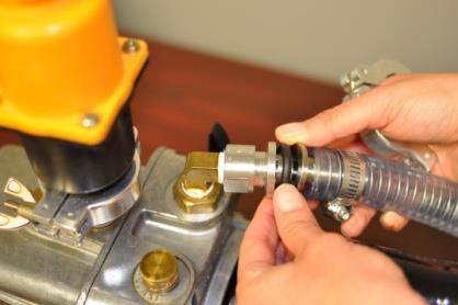
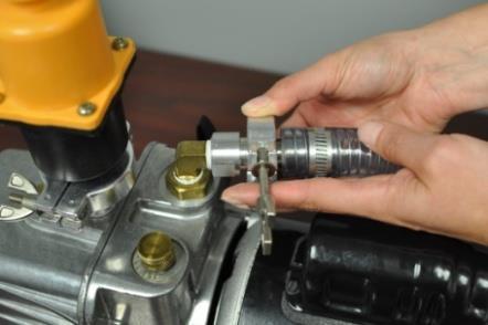
20 MECHANICAL PUMP INSTALLATION The mechanical pump installed Step #1: Installation of vacuum hose to the pump Copyright Denton Vacuum, LLC. All Rights Reserved. Version da 19


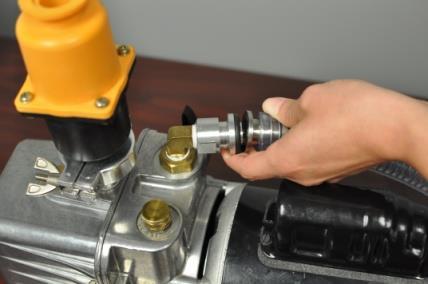
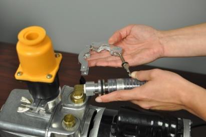
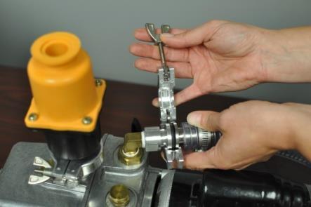
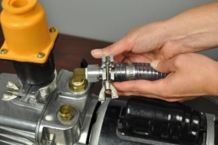
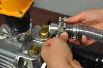
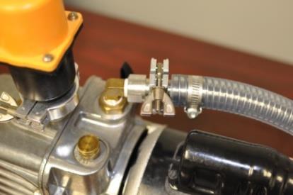
21 Step #2 - Installation of vacuum hose to the rear of the DESK V Step #3 - Mist Filter Installation Check oil level in the mechanical pump. If the oil level is ½ full in the sight glass, the pump is ready. For detailed instructions, refer to the Maintenance section of this manual. MAKE SURE THE POWER SWITCH ON THE MECHANICAL PUMP IS IN THE ON POSITION!!!!! Copyright Denton Vacuum, LLC. All Rights Reserved. Version da 20

22 TARGET INSTALLATION & REPLACEMENT T o ol s R eq uir ed Small Phillips screwdriver & target a Open sputter head 2. Remove grid screen 3. Remove retaining ring 4. Center target on plate 5. Replace retaining ring 6. Replace grid screen and close sputter head The Desk V is ready for operation. Copyright Denton Vacuum, LLC. All Rights Reserved. Version da 21
23 INITIAL START-UP INSPECTION Before starting up the unit, make sure the following are provided: Verify that the incoming power connection is set for the proper voltage! VAC, 60Hz, 10-amp service or 220VAC, 50Hz, 8 Amps. Verify that the incoming voltage connection is set for the proper voltage setting psig-argon gas (or room air, if deemed adequate). 3. All lines are properly connected and there are no loose wires, hoses, or hardware. 4. Check rotary motion: (optional) Make sure the small sprocket is spaced from feedthrough nut by at least 1/16". Make sure that the chain is not tight. It should be slightly limp. Check the mechanical pump oil level only after it has been running for a few minutes. This will give the oil a chance to be distributed throughout the pump and will give a more accurate level reading. Turn the mechanical off before checking oil level Copyright Denton Vacuum, LLC. All Rights Reserved. Version da 22
24 START-UP PROCEDURE To start-up the system, use the following procedure: 1. Turn ON Main Power. 2. Press the START button on the touch screen. 3. Select the desired operating screen from the on-screen menu. Manual or Timed Sputter Manual or Timed Etch Overview 4. Operation of the system is described in detail in the Operation section of this manual. Copyright Denton Vacuum, LLC. All Rights Reserved. Version da 23

25 OPENING THE CHAMBER Be sure that chamber is vented (mechanical pump is off). Grasp the underside of the metal top plate. Lift vertically and tilt the plate back towards the support post. The top plate is hinged to the post. To replace the sputter head on the cylinder reverse the procedure. facing up. NOTE: The sputter head WILL only Tilt 180 degrees so the target is Grasp under side of top plate and lift. Tilt it back so that the target faces up. Copyright Denton Vacuum, LLC. All Rights Reserved. Version da 24
26 DESCRIPTION OF CONTROLS SYSTEM START SCREEN The Desk V system is semi-automatic and is controlled by a PLC. The operator interface is a touch panel with graphical interface to the PLC. Graphical interface is supported with software. Manual operation of valves, pump, power supply, and fixture rotation subsystems is through this graphical interface. Timed processes are also operated through this interface. This software links the operator to the PLC. It allows for control input and data display. This software is active when power is applied to the system. The Start Screen is visible only when the control system is first started. Pressing the START button will provide access to the control system. NOTE: This section of the operating manual describes controls for the Standard Desk V as well as the Desk TSC. There are differences between the two. Copyright Denton Vacuum, LLC. All Rights Reserved. Version da 25
27 SCREENS Standard Desk V & Desk V TSC Access to all control screens is available on this screen. Each system function is described in detail later in this section of the Operating Manual Manual Sputter Provides access to the manual operation of the sputter controls. Pump(s), Sputter Power, Sputter Set point (mamps), Auto Vent Enabled (available only with TSC option), Substrate Rotation (option) and Gas Valve controls are available from this screen. System parameters are displayed on this screen: Chamber Pressure (Torr), DC Current, Speed Indicator (available only with TSC option), Vent Time Remaining (available only with TSC option), and Sputter Set point (mamps). Timed Sputter Provides access to the timed operation of the sputter controls. Process Set point (Torr), Sputter Set point (mamps), Process Time (seconds), and Vent after Sputter Enabled are programmed from this screen. System parameters are displayed on this screen: Vent after Sputter Enabled Indicator and Timed Sputter Enabled Indicator. Manual Etch Provides access to the manual operation of the etch controls. Pump(s), Etch Power, Etch Set point (mamps), Auto Vent Enabled (available only with TSC option), Substrate Rotation (option) and Gas Valve controls are available from this screen. System parameters are displayed on this screen: Chamber Pressure (Torr), DC Current, Speed Indicator (available only with TSC option), Vent Time Remaining (available only with TSC option), and Etch Set point (mamps). Timed Etch Provides access to the timed operation of the etch controls. Process Set point (Torr), Etch Set point (mamps), Process Time (seconds), and Vent after Etch Enabled are programmed from this screen. System parameters are displayed on this screen: Vent after Etch Enabled Indicator and Timed Etch Enabled Indicator. Copyright Denton Vacuum, LLC. All Rights Reserved. Version da 26
28 Overview - This screen is used to display current system status and the state of vacuum Chamber and pumping system. Chamber Pressure (Torr), Process Set point (Torr), DC Current, and Process Time Remaining (Seconds) are displayed. All system controls are implemented by using the touch screen. All subsystem controls are available on individual control screens Subsystem controls are available on the following control screens: Manual Sputter manual operation of the Sputter process. Timed Sputter Timed operation of the Sputter process. Manual Etch manual operation of the Etch process. Timed Etch Timed operation of the Etch process. Process parameters (set point and real) and system controls are displayed on the appropriate screens. MANUAL SPUTTER Standard Desk V HP Manual Sputter operations are available on this screen. Select Manual Sputter from the Screens menu. ON/OFF operation of the Mechanical Pump, Gas Valve, Rotation (if equipped), and Sputter Power Supply is available on this screen. Inactive buttons are RED. Buttons will switch to GREEN when active. Safety interlocks are in place to prevent unsafe operation of the sputter power supply. The Copyright Denton Vacuum, LLC. All Rights Reserved. Version da 27
29 power supply will not turn ON unless all safety interlocks are satisfied. Copyright Denton Vacuum, LLC. All Rights Reserved. Version da 28

30 NOTE: Sputter Set point must be set before power supply is turned ON. NOTE: Power Supply is interlocked to chamber pressure set point of 5.0 e-1 Torr. The Power supply will NOT turn ON above this chamber pressure. The power supply will not turn on unless the Gas Valve is ON. Sputter set point allows for adjustment of the power set point of the Sputter Power supply. A pop-up data entry screen is available by pressing the set point data box. The current Sputter set point is displayed. NOTE: Sputter set point range is milliamps. Electrical Current output of the Power Supply is displayed in milliamps. Current Chamber Pressure is displayed in Torr. The Overview button will return to the Overview screen. The Screens button will return to the Screens menu. MANUAL SPUTTER DESK V TSC Manual Sputter operations are available on this screen. Select Manual Sputter from the Screens menu. ON/OFF operation of the Pumps(s), Gas Valve, Rotation (if equipped), and Sputter Power Supply is available on this screen. The Auto Vent Enabled function is available on this screen. This feature will shut down the pumps and safely vent the chamber to atmosphere. The Vent Time Remaining will count down the delay required before venting the chamber to atmosphere. Copyright Denton Vacuum, LLC. All Rights Reserved. Version da 29
31 WARNING! Ten (10) minutes must elapse between turning off the turbo pump and turning off the mechanical pump, or the turbo pump will be damaged. Inactive buttons are RED. Buttons will switch to GREEN when active. Safety interlocks are in place to prevent unsafe operation of the sputter power supply. The power supply will not turn ON unless all safety interlocks are satisfied. NOTE: Sputter set point must be set before power supply is turned ON. NOTE: Power Supply is interlocked to chamber pressure set point of 5e-1 Torr. The Power supply will NOT turn ON above this chamber pressure. The power supply will not turn on unless the Gas Valve is ON. Sputter set point allows for adjustment of the power set point of the Sputter Power supply. A pop-up data entry screen is available by pressing the set point data box. The current Sputter set point is displayed. NOTE: Sputter set point range is milliamps. Electrical Current output of the Power Supply is displayed in milliamps. Current Chamber Pressure is displayed in Torr. Vent Time Remaining is displayed in seconds. Speed indicator will display when turbo pump is at full operating speed (if equipped). The Overview button will return to the Overview screen. The Screens button will return to the Screens menu. Copyright Denton Vacuum, LLC. All Rights Reserved. Version da 30
32 TIMED SPUTTER S t andar d D es k V HP Timed Sputter operations are available on the Timed Sputter screen. Select Timed Sputter from the Screens menu. Inactive buttons are RED. Buttons will switch to GREEN when active. NOTE: Sputter set point must be set before power supply is turned ON. NOTE: Power Supply is interlocked to chamber pressure set point of 5e-1 Torr. The Power supply will NOT turn ON above this chamber pressure. The power supply will not turn on unless the Gas Valve is ON. The system will automatically pump down to 4.0e-2 Torr before activating the Timed Sputter process. Timed Sputter processes can be started with the chamber at atmospheric pressure or from any pressure, but the sputtering process will not begin above 4.0e-2 Torr. Sputter set point allows for adjustment of the power set point of the Sputter Power supply. A pop-up data entry screen is available by pressing the set point data box. The current Sputter set point is displayed. Note: Sputter set point range is milliamps. Process Time allows for adjustment of the Process Timer set point of the Sputter Power supply. A pop-up data entry screen is available by pressing the Process Time data box. The current Sputter Timer set point is displayed. Copyright Denton Vacuum, LLC. All Rights Reserved. Version da 31

33 Note: Process Time set point range is seconds. Process Time Remaining is displayed in seconds. Vent After Sputter Enabled button will enable an automatic vent of the system to atmosphere after the timed sputter is complete. The Timed Sputter running button will start the Sputter power Supply and the Process Timer. The Abort button will end a Timed Sputter process immediately. The Overview button will return to the Overview screen. Desk V TSC Desk TSC Timed Sputter operations are available on the Timed Sputter screen. Select Timed Sputter from the Screens menu. Inactive buttons are RED. Buttons will switch to GREEN when active. NOTE: Sputter set point must be set before power supply is turned ON. NOTE: Power Supply is interlocked to chamber pressure set point of 5.0e-1 Torr. The Power supply will NOT turn ON above this chamber pressure. The power supply will not turn on unless the Gas Valve is ON. Process set point allows for adjustment of the process pressure start set point. A pop-up data entry screen is available by pressing the set point data boxes. The current Process set point is displayed. Copyright Denton Vacuum, LLC. All Rights Reserved. Version da 32
34 The system will automatically pump down to the Process set point before activating the Timed Sputter process. Timed Sputter processes can be started with the chamber at atmospheric pressure or from any pressure, but the sputtering process will not begin above the Process set point. Sputter set point allows for adjustment of the power set point of the Sputter Power supply. A pop-up data entry screen is available by pressing the set point data box. The current Sputter set point is displayed. Note: Sputter set point range is mamps standard. Process Time allows for adjustment of the Process Timer set point of the Sputter Power supply. A pop-up data entry screen is available by pressing the Process Time data box. The current Sputter Timer set point is displayed. Note: Process Time set point range is seconds. Process Time Remaining is displayed in seconds. Vent After Sputter Enabled button will enable an automatic vent of the system after the timed sputter is complete. The Timed Sputter running button will start the Sputter power Supply and the Process Timer. The Abort button will end a Timed Sputter process immediately. The Overview button will return to the Overview screen. Copyright Denton Vacuum, LLC. All Rights Reserved. Version da 33


, Process")


35 Desk V Timed Recipe Programming Timed Recipe Programming provides access to the creation and storage of up to 10 separate recipes. Parameters include Recipe Name, Process Set points (Torr and milliamps), Process Time (seconds), Vent after Sputter Select and Timed Sputter Enable. Timed Sputter Recipe Parameters Screen Timed Etch Recipe Parameters Screen Below are the Timed Recipe Parameter screens for both sputter and etch functions. Sputter With Turbo Etch With Turbo Without Turbo Without Turbo 34
.")
36 To input data, touch cell. NOTE: The difference between with turbo and without turbo in recipe programming is that when using a turbo molecular pump, one can select pressure settings (as found in set point 1 and set point 2). How to Use Timed Recipe Programming To create a Timed Recipe from the Timed Sputter screen, select Recipe. This will bring you to the Recipe page. Touch the cell under the Recipe Name portion of the table to open the keyboard. From there, enter the name of the recipe you wish to create and save. To input other values, simply touch the cell in which you wish to input a value. With recipes created and stored, your recipe name will now be displayed on the timed sputter page. To engage a recipe, simply select the recipe name from the drop down menu and press the send recipe button. The program will automatically bring you to the timed sputter page. If you selected enabled timed sputter for a recipe, your process will begin after the timed sputtering page appears. NOTE: If you change the parameters at any time after the recipe has been sent, the recipe name will disappear from the timed sputter page. Changes made on the timed sputter page will not be saved on your recipe page. However, the system will still be functional with the new parameters. 35
37 A few notes regarding operation of the Timed Recipe Programming follow: The system will automatically pump down to the Process set point before activating the Timed Sputter process. Timed Sputter processes can be started with the chamber at atmospheric pressure or from any pressure, but the sputtering process will not begin above the Process set point. The Timed Recipe Program provides the following data input fields: TIMED SPUTTER RECIPE PROGRAMMING VALUE SELECTIONS Recipe Number: can create and store up to 10 recipes. Recipe Name: alphanumeric and up to 10 characters. Process Setpoint1: base number (in Torrs) Process setpoint2: exponent (in Torrs) Example: setpoint1 (5) and setpoint2 (3) is equivalent to 5-3 (five to the minus three) Torr Sputter set point: power setting in mamps (0 to 100 range). Process Time: up to 600 seconds. Vent after Sputter Select: enables an automatic vent of the system after the timed sputter is complete. Timed Sputter Enable: starts Sputter power Supply and the Process Timer (in seconds). TIMED ETCH RECIPE PROGRAMMING VALUE SELECTIONS Recipe Number: Can create and store up to 10 recipes. Recipe Name: alphanumeric and up to 10 characters. Process Setpoint1: base number (in Torrs) Process setpoint2: exponent (in Torrs) Example: set point 1 (5) and set point 2 (3) is 5-3 (five to the minus three) Torr Etch set point: power setting in mamps (0 to 10 range). Process Time: up to 600 seconds. Vent after Etch Select: enables an automatic vent of the system after the timed sputter is complete. Timed Etch Enable: starts Sputter power Supply and the Process Timer (in seconds). 36
38 MANUAL ETCH NOT an option with Rotation. DESK V HP Manual Etch operations are available on the Etch screen. Select Manual Etch screen from the Screen menu. Standard Desk V HP ON/OFF operation of the Mechanical Pump, Gas Valve, and Etch Power Supply is available on this screen. Inactive buttons are RED. Buttons will switch to GREEN when active. NOTE: Etch Set point should be set before power supply is turned ON. NOTE: Power Supply is interlocked to chamber pressure set point of 5.0e-1 Torr. The Power supply will NOT turn ON above this chamber pressure. The power supply will not turn on unless the Gas Valve is ON. Etch set point allows for adjustment of the power set point of the Etch Power supply. A popup data entry screen is available by pressing the set point data box. The current Etch set point is displayed. Note: Etch Power set point range is 0 10 Milliamps standard. Current chamber pressure is displayed in Torr. The Overview button will return to the Overview screen. 37
39 The Screens button will return to the Screens menu. 38
40 Select Manual Etch screen from the Screen menu. DESK TSC ETCH is not an option with rotation. Manual Etch operations are available on the Etch screen. ON/OFF operation of the Mechanical Pump, Gas Valve, and Etch Power Supply is available on this screen. NOTE: Etch set point should be set before power supply is turned ON. NOTE: Power Supply is interlocked to chamber pressure set point of 5.0e-1 Torr. The Power supply will NOT turn ON above this chamber pressure. The power supply will not turn on unless the Gas Valve is ON. Etch set point allows for adjustment of the power set point of the Etch Power supply. A popup data entry screen is available by pressing the set point data box. The current Etch set point is displayed. Note: Etch Power set point range is 0 10 milliamps. Current chamber pressure is displayed in Torr. The Overview button will return to the Overview screen. The Screens button will return to the Screens menu. 39

41 TIMED ETCH ETCH IS NOT AN OPTION WITH ROTATION Timed Etch operations are available on the Timed Etch screen. Select Timed Etch from the Main screen. ON/OFF operation of the Etch Power Supply is a push button on this screen. Inactive buttons are RED. Buttons will switch to GREEN when active. NOTE: Etch set point should be set before power supply is turned ON. NOTE: Power Supply is interlocked to chamber pressure set point of 5.0e-1 Torr. The Power supply will NOT turn ON above this chamber pressure. The power supply will not turn on unless the Gas Valve is ON. Etch set point allows for adjustment of the power set point of the Etch Power supply. A popup data entry screen is available by pressing the set point data box. The current Etch set point is displayed. Note: Etch Power set point range is 0 10 milliamps. Process Time allows for adjustment of the Process Timer set point of the Etch Power supply. A pop-up data entry screen is available by pressing the Process Time data box. The current Sputter Timer set point is displayed. 40

42 Note: set point range is seconds. The Timed Etch Running button will start the Etch power supply and the Process Timer. Vent After Etch Enabled button will enable an automatic vent of the system after the timed etch is complete. The Abort button will end a Timed Etch process immediately. The Overview button will return to the Overview screen. Desk V TSC Timed Etch operations are available on the Timed Etch screen. Note: Turbo Pump must be OFF to operate the Manual Etch function. Select Timed Etch from the Main screen. ON/OFF operation of the Etch Power Supply is a push button on this screen. Inactive buttons are RED. Buttons will switch to GREEN when active. NOTE: Etch set point should be set before power supply is turned ON. NOTE: Power Supply is interlocked to chamber pressure set point of 5.0e-1 Torr. The Power supply will NOT turn ON above this chamber pressure. The power supply will not turn on unless the Gas Valve is ON. Etch set point allows for adjustment of the power set point of the Etch Power supply. A popup data entry screen is available by pressing the set point data box. The current Etch set point is displayed. 41

43 Note: Etch Power set point range is 0 10 milliamps. Process Time allows for adjustment of the Process Timer set point of the Etch Power supply. A pop-up data entry screen is available by pressing the Process Time data box. The current Sputter Timer set point is displayed. Note: set point range is seconds. The Timed Etch Running button will start the Etch power supply and the Process Timer. Vent After Etch Enabled button will enable an automatic vent of the system after the timed etch is complete. The Abort button will end a Timed Etch process immediately. The Overview button will return to the Overview screen. OVERVIEW DESK V HP Select Overview from any other screen. All active system parameters are graphically displayed on the Overview screen. Current chamber pressure is displayed in Torr. Inactive graphics are RED. Graphics will switch to GREEN when active. Note the PINK in the graphic above. This indicates that the sputter and etch are in operation. The DC Current is displayed in milliamps. 42

44 ON/OFF operation of the subsystems (pumps, valves, rotation, sputter, and etch) is Graphically displayed on this screen. Process Time Remaining is displayed in seconds. Text messages are displayed on this screen to indicate current active operation in the control system. These messages will describe the current active operation as follows: Message Auto Sputter Without Vent Auto Sputter With Vent Auto Etch Without Vent Auto Etch With Vent System Auto Venting Active Operation(s) - Timed Sputter is enabled; Vent After Sputter is NOT enabled. - Timed Sputter is enabled; Vent After Sputter is enabled. - Timed Etch is enabled; Vent After Sputter is NOT enabled. - Timed Etch is enabled; Vent After Sputter is enabled. - Ten minute delay timer is counting down. Desk V TSC only. NOTE: The Abort button will stop a Timed Sputter or Etch process immediately. The Screens button will return to the Screens menu. Desk TSC All active system parameters are graphically displayed on the Overview screen. Select Overview from any other screen. Inactive graphics are white. Graphics will switch to black when active. 43
45 Current chamber pressure is displayed in Torr. The Process set point is displayed in Torr. The DC Current is displayed in milliamps. ON/OFF operation of the subsystems (pumps, valves, rotation, speed, sputter, and etch) is graphically displayed on this screen. Process Time Remaining is displayed in seconds. The Vent Time Remaining is displayed in seconds. Text messages are displayed on this screen to indicate current active operation in the control system. These messages will describe the current active operation as follows: Message Auto Sputter Without Vent Auto Sputter With Vent Auto Etch Without Vent Auto Etch With Vent System Auto Venting Active Operation(s) - Timed Sputter is enabled; Vent After Sputter is NOT enabled. - Timed Sputter is enabled; Vent After Sputter is enabled. - Timed Etch is enabled; Vent After Sputter is NOT enabled. - Timed Etch is enabled; Vent After Sputter is enabled. - Ten minute delay timer is counting down. Desk V TSC only. NOTE: The Abort button will stop a Timed Sputter or Etch process immediately. The Screens button will return to the Screens menu. OPERATION This section of the manual will describe manual and timed operation of the system. A brief description is provided for a better understanding of the operation of the system. A complete understanding of the Control System is required before operating the system. Read the Description of Controls section of this manual before proceeding! Copyright Denton Vacuum, LLC. All Rights Reserved. Version da 44
46 The Denton Vacuum DESK V Cold Sputter/Etch Unit is designed to clean the surface of SEM specimens and to deposit a heavy metal conductive coating on the clean surface. A standard 6 diameter by 6 high Pyrex Cylinder with top and bottom Seals sits on an aluminum Baseplate. (6 D. x 6 H. Metal Chamber on TSC) The cylinder is evacuated by a two-stage, direct-drive, Mechanical Pump (externally mounted) and a turbo pump (Desk V TSC only), which is mounted to a flange in the side of the metal chamber. The mechanical pump provides rough vacuum and the turbo molecular pump (Desk V TSC only) provides pumping into the high vacuum range. An automatic Vent Valve is slaved to the mechanical pump. It will automatically open when the Mechanical Pump is turned OFF to vent the chamber to atmosphere. It will automatically close when the Mechanical pump is turned on. An insulated Specimen Table with provisions for height adjustment is mounted within the Pyrex cylinder. The Sputter Cathode is clamped to an insulated aluminum plate in the chamber cover. The Desk V contains a single high voltage power supply. The output of the power supply is connected to the substrate fixture for Etch and to the Sputter Cathode for Sputter deposition. Power output varies: Etch = 0-10 milliamps; and Sputter = milliamps. A manual Shutter is provided as the etch electrode and to shield the Sputter Cathode from contamination during the Etch cleaning cycle. The shutter control knob is left of the chamber. Clockwise rotation of the knob will open the shutter and counterclockwise rotation will close it. A manual Gas Control is provided to control pressure in the cylinder. The Gas Control knob is to the left of the chamber. The standard Desk V is equipped with a vacuum gauge to provide vacuum pressure measurements in the vacuum chamber down to the limit of the mechanical pump. The Desk V TSC is equipped with a full range gauge to provide vacuum pressure measurements down to the limits of the turbo molecular pump. ETCH NOT an option with Rotation. Remove rotation Fixturing and install non-rotating fixture plate before proceeding! Note: Turbo Pump must be OFF to operate the Manual Etch function. Copyright Denton Vacuum, LLC. All Rights Reserved. Version da 45

47 Standard Desk V HP Desk TSC NOTE: Shutter must be in the closed position (knob fully clockwise) From the Manual Etch screen, turn the Mechanical Pump ON. Wait for the Vacuum pressure to drop below 4.0e-2 Torr. With the mechanical pump running, turn the Gas Valve ON. Stabilize at between 1.5e-1 and 2.0e-1 Torr by adjusting the Gas flow control knob. Gas Flow valve clockwise = decrease flow, reduce pressure. Gas Flow valve counter-clockwise = increase flow, increase pressure. Close the Shutter From the Manual Etch screen, with the Etch set point at a non-zero value. Increase the Etch set point to desired level (0-10 milliamps). Actual current will be displayed on the Manual Etch and the Overview screens. Turn the Etch Power On. Etch for the desired time. Copyright Denton Vacuum, LLC. All Rights Reserved. Version da 46
48 Turn OFF the Etch Power. Shut the Gas Valve OFF. SPUTTER NOTE: Do not run the Etch supply for more than ten minutes. NOTE: Do not close the manual Gas Flow valve. Leave this set to the desired gas flow required for the Timed Etch process. NOTE: Once the desired settings of time, etch level, and gas flow have been established and set, the timed mode of operation can be used. NOTE: Sputtering pressure can be reached with or without the use of the optional Turbo Molecular pump (Desk V TSC only). Experimentation is required to adjust the gas flow/pumping speed combination required for your individual process requirements. Standard Desk V HP Desk TSC For the Desk V HP: From the Manual Sputter screen, turn the mechanical pump ON. Wait for the Vacuum pressure to drop below 4.0e-2 Torr. For DESK V TSC: Turn ON the optional Turbo Molecular pump and wait for the pressure to drop to the desired starting vacuum level. NOTE: Sputtering pressure setting for the Desk V TSC is between 5.0E-3 to 7.0E-3. The pressure must be less than1.0e+00 (1 TORR) before turning the Turbo Pump ON. Continue pumping and open the Gas Valve. Copyright Denton Vacuum, LLC. All Rights Reserved. Version da 47
49 Gas Flow valve clockwise = decrease flow, reduce pressure. Gas Flow valve counter-clockwise = increase flow, increase pressure. NOTE: Additional gas flow may be required when using a new target. Turn Rotation ON (if equipped). Open Shutter From the Manual Sputter screen, turn Sputter Power On with the Sputter set point at a nonzero value. Increase the Sputter set point to desired level (0-100 milliamps). Actual current will be displayed on the Manual Sputter and the Overview screens. Sputter for the desired time. Turn OFF the Sputter Power and reduce the Sputter set point to zero. Shut the Gas Valve OFF. NOTE: Do not close the manual Gas Flow valve. Leave this set to the desired gas flow required for the Timed Sputter process. Turn OFF the optional Turbo pump (Desk V TSC) from the Vacuum screen. The system control will wait ten (10) minutes before turning off the Mechanical Pump (to protect the turbo pump). After ten (10) minutes, turn OFF the Mechanical Pump. The automatic Vent Valve will open to vent the chamber to atmosphere. NOTE: Once the desired settings of time and power, and gas flow have been Established and set, the Timed mode of operation can be used. WARNING! Ten (10) minutes must elapse between turning off the turbo pump and turning off the mechanical pump, or the turbo pump will be damaged. Copyright Denton Vacuum, LLC. All Rights Reserved. Version da 48


50 TIMED ETCH OPERATION Standard Desk V Desk TSC NOTE: Shutter must be in the closed position (knob fully clockwise) Set the desired Etch power set point. Set the desired Process Time set point. Select Vent after Etch enables if desired. NOTE: The manual Gas Flow valve should have been manually set to the desired gas flow required for the timed process. Note: Turbo Pump must be OFF to operate the Manual Etch function. Activate the Timed Etch Running button and the system will operate as follows: Mechanical Pump will start and pump the chamber to the initial vacuum level: 4.0e-2 Torr is the fixed set point for all models. When the fixed set point is reached: The Gas Valve will open (to the manually adjusted flow set point). System will stabilize for 30 seconds. Copyright Denton Vacuum, LLC. All Rights Reserved. Version da 49

51 The Etch power supply will turn ON to the set point power level. Power will continue until the Process Timer times out. The power supply will shut OFF and the Gas Valve will close. If the Vent After is enabled, the Mechanical Pump will shut off and the system will vent to atmosphere. If Vent after is not enabled, the power supply will shut OFF and the pumps will remain on. Etch Power set points can be adjusted at any time during this timed operation. WARNING! Ten (10) minutes must elapse between turning off the turbo pump and turning off the mechanical pump, or the turbo pump will be damaged. TIMED SPUTTER OPERATION Standard Desk V Desk TSC Set the desired Sputter power set point milliamps ( 5.0E-3 to 7.0E-3 on TSC Models ) Set the desired Process Time set point seconds. Select Vent after Sputter Enabled if desired. Set the desired Process set point (Desk TSC only). Copyright Denton Vacuum, LLC. All Rights Reserved. Version da 50
52 NOTE: The manual Gas Flow valve should have been manually set to the desired gas flow required for the Timed Process. Activate the Timed Sputter Running button and the system will operate as follows: Pumps will start and pump the chamber to the initial vacuum level: Below 4.0e-2 Torr is the fixed set point for the Standard Desk V. The Process set point is programmable for the Desk V TSC. NOTE: See the Description of Controls section of this manual for instruction on how to program the Process set point. Rotation is ON during this time (if equipped). When the fixed set point or the Process set point is reached: The Gas Valve will open (to the manually adjusted flow set point). System will stabilize for 30 seconds. The Sputter power supply will turn ON to the set point power level. Power will continue until the Process Timer times out. Power supply will shut OFF and Gas Valve will close. If the Vent After is enabled, the pumps will shut off and the system will vent to atmosphere. The ten minute Vent Delay Timer will activate to safely shut down the turbo pump (Desk TSC only). If Vent after is not enabled, the power supply will shut OFF and the pumps will remain on. Sputter power set points can be adjusted at any time during this timed operation. WARNING! Ten (10) minutes must elapse between turning off the turbo pump and turning off the mechanical pump, or the turbo pump will be damaged. Copyright Denton Vacuum, LLC. All Rights Reserved. Version da 51
53 SHUT-DOWN PROCEDURE 1. Turn off all sub-systems (sputter, etch, gas, rotation). 2. For DESK V TSC option, turn off turbo pump, and wait TEN (10) minutes before turning off mechanical pump, or the turbo pump will be damaged. 3. Turn off mechanical pump. WARNING! Ten (10) minutes must elapse between turning off the turbo pump and turning off the mechanical pump, or the turbo pump will be damaged. OPTIONS QUARTZ CRYSTAL MONITOR OPTIONAL Note: Read the operating manual for the deposition controller before proceeding! Deposition Monitors require programming before depositions. The Operating Manual for the appropriate Deposition Monitor is provided with the Desk V system. Please read this manual before proceeding to operate the Desk V system with the Deposition Monitor. The Deposition Monitor will require programming of the following material parameters: Material Density Tooling Factor Acoustic Impedance Thickness Endpoint The Material Density and Acoustic Impedance are provided in a list in the Operating Manual for the Deposition Monitor. The Tooling Factor must be calculated relative to the material and the position of the crystal sensor. A complete definition of these parameters and instructions for calculating each parameter are included in the Operating Manual of the Deposition Monitor. Copyright Denton Vacuum, LLC. All Rights Reserved. Version da 52
54 Deposition with the Deposition Monitor should proceed as follows: 1. Complete the Etch process as described in the Etch section of this manual (if required). 2. Begin the Sputter process as described in the Sputter section of this manual. 3. When the Shutter is opened, start the Deposition Monitor. 4. When the Deposition Monitor reaches the programmed thickness, close the shutter. 5. Power down the Sputter source as described in the Sputter section of this manual. DESK V TSC OPTIONAL Metal vacuum chamber with pump port for Turbo molecular pump on side flange and 2.0 viewport on front replaces the standard Pyrex cylinder. Turbo Molecular pump is operated from the Manual Sputter screen. For proper performance of the TSC system, the following needs to be accomplished: 1. Mechanical pump must be ON until the chamber pressure less than 1.0e+0 Torr ( 1 T o r r ) before turning Turbo Pump ON. 2. Turn on Turbo for 20 minutes. (Previous testing with a hot filament gauge produced 5.0e-6 Torr.) 3. Turn on the Gas Valve, adjust Gas Flow Valve to reach 5.0e-3 to 7.0e-3 Torr and wait for the pressure to stabilize. 4. Set Sputter set point to desired set point. 5. Turn Sputter Power ON. (Plasma will be visible). 6. Turn off Turbo Pump, wait for ten (10) minutes, and then vent system by turning off the mechanical pump. Turbo pump is used to reach high vacuum in the metal Chamber. Gas Control can be used with Turbo Pump to reach process pressure control in the Chamber. WARNING! Ten (10) minutes must elapse between turning off the turbo pump and turning off the mechanical pump, or the turbo pump will be damaged. Copyright Denton Vacuum, LLC. All Rights Reserved. Version da 53
55 WARNING! Never turn system off when turbo pump is running. Turbo pump must be turned off before turning system off. CARBON ROD ACCESSORY OPTIONAL Caution! The bright light from the carbon evaporation source can damage the optic nerve. NEVER look at a heated source without eye protection such as a welder s glasses or a coated piece of glass such as one might use to watch a solar eclipse. Requi rements 120/220 VAC; 10/5 amp electrical outlet. Emery board or file - used to flatten sections of carbon rod. 1/16 diameter swizzle stick to push carbon rods through opening in sleeves. Welder s goggles (shade #5 or higher) to observe evaporation process. Carbon Rods, x 2.0, sharpened (100 per pack) = DVI part number CAR WARNING! Use dark glass to observe carbon evaporation. Intense brightness is harmful to eyes when viewed directly. Sample Prep To check your carbon evaporation technique, before coating samples, do the following: 1. Coat a glass cover slip with gold. 2. When the cover slip is over coated, the gold color will change: To copper with 100 Å of carbon To orange with 150 Å of carbon To purple with 200 Å Copyright Denton Vacuum, LLC. All Rights Reserved. Version da 54
56 Operation The Desk V sputter head must be flipped over. Replace the standard 6.0 diameter by 6.0 high Pyrex cylinder with the 6" D. x 9" H. Pyrex cylinder. Mount the Carbon Rod accessory plate to the top of the larger Pyrex cylinder. The Desk V vacuum pumping system can be used to evacuate a Pyrex cylinder with a carbon evaporation source mounted in the metal cover. The source can be mounted so as to vary the source-to-specimen distance from 3-1/2 to 5. Two carbon rods are positioned in the center of the yoke to do the coating. One rod will have a point or reduced section. The other will have a full diameter section that has been carefully flattened on the end touching the point (or reduced section) of the other rod. Both carbon rods should be inserted, one after another, through the outside end of the fixed rod holder. First, the pointed rod should be inserted (point trailing) and pushed through with the flattened carbon rod to move into the moving rod holder. Continue pushing the rods until the spring is deflected about 1/8 inch. Tighten the thumbscrew holding the flattened carbon in the fixed holder. If using a reduced section carbon rod, the spring should be moved out a little more than the length of the reduced carbon. With the carbon source loaded, place the Pyrex cylinder on the baseplate, seat the source head, and start pump down. Within two to three minutes, the chamber vacuum gauge should read about 5.0e-2 Torr. Turn on FILAMENT POWER on the Carbon Evaporation Module. Rotate power stat clockwise to obtain 15 amp reading on ammeter. Carbon point should be bright red and outgassing. Increase filament power to 28 to 32 amps until a light spark is seen. DO NOT exceed 50 amps on the meter. WARNING! Use dark glass to observe carbon evaporation. Intense brightness is harmful to eyes when viewed directly. At 4 source-to-specimen, about 1/8 length of.040 inches reduced section will deposit about 100 angstroms of carbon. For evaporating at relatively high pressure, it is good practice to check carbon film thickness. Coat a glass cover slip with gold. The gold color will change to copper when the cover slip is over-coated with 100 angstroms of carbon; to orange with 150 angstroms of carbon; to purple with 200 angstroms of carbon. Copyright Denton Vacuum, LLC. All Rights Reserved. Version da 55
57 At 5.0e-2 Torr, the average gas molecule travels about.04 between collisions. With a source-tospecimen distance of 4, the carbon will make many collisions. It will arrive from all available directions. Above 7.5e-2 Torr, the thickness of the carbon film will diminish rapidly, as compared to the expected thickness. If the carbon chamber will not pump below 1.0e-1 Torr, check by substituting the Desk V chamber. If that pumps down, then the trouble is probably with the L gaskets on the carbon chamber. Wipe them clean with a lint free cloth and Isopropanol Alcohol. Apply a thin coating of vacuum grease to the gasket on the glass side and on the baseplate side. General Notes The chamber should first be pumped to 5.0 e-2 Torr or less. Denton Vacuum supplies a carbon of excellent quality. It is suggested that a low power setting, to degas the carbon, be used; slowly raise to evaporate. Degas the carbon (bright red) for 5 to 10 seconds. (Watch the chamber pressure rise, and then start to fall back.) Carbon may be evaporated slowly or rapidly. Normally, after degassing, the power is increased to where the carbon starts depositing. Length of evaporation time will depend on the desired thickness of carbon film. It should take from 30 seconds to totally evaporate the carbon. DO NOT take power too high for more than one minute. NEVER EXCEED 50 AMPS. A rapid evaporation (flashing) may be utilized by presetting the control to 75 percent of dial rotation, and then turning on the power. The flash will last from 1 to 2 seconds and help reduce heat damage. Copyright Denton Vacuum, LLC. All Rights Reserved. Version da 56
58 CARBON YARN ACCESSORY OPTIONAL Caution! The bright light from the carbon evaporation source can damage the optic nerve. NEVER look at a heated source without eye protection such as a welder s glasses or a coated piece of glass such as one might use to watch a solar eclipse. Req uirements 120/220 VAC; 10/5 amp electrical outlet. Welder s goggles (shade #5 or higher) to observe evaporation process. Carbon Yarn (25 feet) = DVI part number YRN WARNING! Use dark glass to observe carbon evaporation. Intense brightness is harmful to eyes when viewed directly. Sample Prep To check your carbon evaporation technique, before coating samples, do the following: 1. Coat a glass cover slip with gold. 2. When the cover slip is over coated, the gold color will change: Operation To copper with 100Å of carbon To orange with 150 Å of carbon To purple with 200 Å The Desk V sputter head must be rotated to the side. Replace the standard 6.0 diameter by 6.0 high Pyrex cylinder with the 6" D. x 9" H. Pyrex cylinder. Mount the Carbon Yarn accessory plate to the top of the larger Pyrex cylinder. Copyright Denton Vacuum, LLC. All Rights Reserved. Version da 57
59 DO NOT permit the mounting post to touch the pump-out cover, which is at baseplate ground. This would short the filament current directly to ground. The Carbon Yarn Evaporation Source is adjustable and is designed to provide carbon films for support, replication or conduction. The mounting posts are drilled and tapped to screw onto the pair of low-voltage feedthroughs. The rectangular extension blocks connect to the upper posts. This arrangement gives flexibility to locate the source as desired. Each block contains a spring-loaded terminal to attach each end of the carbon yarn. By depressing the spring-loaded terminal, the carbon yarn may be clamped. The carbon yarn evaporation unit is designed to use high-purity carbon yarn. The height is adjustable by loosening the screw holding the unit to the mounting post. Loading the Carbon Yarn The carbon yarn is placed across two spring-loaded electrode posts. (Carbon sublimes i.e., it goes from a solid to a gas with no liquid phase). When reloading, allow time for posts to cool as they get quite hot, especially when firing carbon for 30 seconds or longer. General Notes The chamber should first be pumped to 50 m Torr or less. Denton Vacuum supplies a carbon of excellent quality. It is suggested that a low power setting, to degas the carbon, be used; slowly raise to evaporate. Degas the carbon (bright red) for 5 to 10 seconds. (Watch the chamber pressure rise, and then start to fall back.) Carbon may be evaporated slowly or rapidly. Normally, after degassing, the power is increased to where the carbon starts depositing. Length of evaporation time will depend on the desired thickness of carbon film. It should take from 30 seconds to totally evaporate the carbon. DO NOT take power too high for more than one minute. NEVER EXCEED 50 AMPS. A rapid evaporation (flashing) may be utilized by presetting the control to 75 percent of dial rotation, and then turning on the power. The flash will last from 1 to 2 seconds and help reduce heat damage. Carbon vaporizes due to localized heat caused by resistance to flow of electric current. Carbon resistance lowers as carbon heats up, but will stabilize. Copyright Denton Vacuum, LLC. All Rights Reserved. Version da 58
60 MAINTENANCE GENERAL MAINTENANCE The Desk V will operate more efficiently if kept clean. Scale build-up on the baseplate should be cleaned off weekly and the surface cleaned with Isopropanol alcohol using a lint free cloth or paper and solvent. Be sure all debris is vacuumed away. Clean coating build-up from the cylinder with a metal polish. "Wenol" and "Pol" are recommended. These polishes clean off the coating deposit and polish the glass. To ensure a proper vacuum seal, inspect the cylinder and gaskets for nicks, cracks, and other foreign material. Apply a thin coat of vacuum grease to the gaskets and immediately wipe off the grease to prevent excessive grease build-up. Inspect the sealing surface for nicks or scratches. These must be smoothed out with emery and polished with fine emery or Scotch Brite. Any deposit build-up must be similarly removed and the entire surface wiped clean with Isopropanol alcohol using a lint-free cloth. Vacuum the baseplate to remove all debris and powder deposits. MECHANICAL PUMP Mechanical pump oil should be changed annually or whenever it becomes contaminated. Check oil level and condition. If the oil appears cloudy or brownish, it needs changing. The oil is changed by opening the drain outlet of the Mechanical Pump. CAUTION! DO NOT ATTEMPT TO RE-ALIGN, OR MOVE DRAIN VALVE IN EITHER DIRECTION. METAL CASTING WILL BE DAMAGED. USE PLASTIC TUBING IF NECESSARY TO FACILITATE DRAIN. Copyright Denton Vacuum, LLC. All Rights Reserved. Version da 59
61 MECHANICAL PUMP OIL CHANGE The pump contains oil. WARNING! Check the oil level before starting the machine. Mechanical pumps may vary. Typical pump shown on pages Check oil level at sight port. TOOLS REQUIRED Drain pan. Should the pump require additional oil, proceed as follows: 1. The drain valve is the brass screw mounted at the lower end of the pump body. 2. Place drain pan under drain hole, under the pump. 3. Turn the drain valve counterclockwise. 4. It is not necessary to remove the screw. 5. Tilt the pump forward and drain until flow stops. 6. Turn drain screw clockwise until closed. 7. Remove drain pan. Discard oil following EPA guidelines. 8. Refill with new oil by removing the brass fill plug at the top of the pump body. 9. Fill to the top of the OIL LEVEL line on the sight port. SPUTTER TARGET TOOLS REQUIRED Small Phillips screwdriver & target INSTRUCTIONS 1. Open sputter head 2. Remove grid screen 3. Remove retaining ring 4. Center target on plate 5. Replace retaining ring Copyright Denton Vacuum, LLC. All Rights Reserved. Version da 60

62 6. Replace grid screen and close sputter head a PLASMA PROBLEMS If the plasma is flickering during sputtering, the problem is a high voltage short or starvation of gas. Add more gas before checking other possibilities. Copyright Denton Vacuum, LLC. All Rights Reserved. Version da 61
63 1. If during etching, take the pedestal apart and clean. 2. If during sputtering, take the sputter head apart and clean. Call the factory if guidance is needed in this area ( ). TROUBLESHOOTING DESK V TROUBLESHOOTING GUIDE FAULT PROBABLE CAUSE ACTION 1. No power a. 120/220 VAC not present at line cord b. System ON switch is defective or off. c. Blown fuse. 2. Mechanical pump will not start 3. Chamber will not pull vacuum 4. Sputter head seals, but vacuum is poor. a. Blown fuse. b. Bad connection. c. Pump switch off a. Check oil level in mechanical pump. b. Inspect bell jar gaskets for cracks on sealing surface. c. Inspect bell jar for chips across sealing surface. d. Vent valve open. e. Vacuum leak in system. a. Cracked bell jar gaskets. b. Chip on bell jar. c. Low oil level in mechanical pump. d. Dirty oil in mechanical pump. e. Vacuum leak in system. f. Pirani gauge tube bad or dirty. g. Turbo pump off [turbo a. Check AC receptacle. b. Press switch to the ON position or replace. c. Replace 10 amp Fuse, located in the power connection a. Replace 8-amp F1 fuse located on rear panel. b. Check all cables attached to mechanical pump. c. Check switch on mechanical pump a. Fill oil level until it reaches center of sight glass. b. Replace old gaskets if bad. c. Replace bell jar if chips are across sealing surface. d. Missing 24 VDC at vent valve connector or defective valve. e. Locate and seal vacuum leak. a. Replace gaskets. b. Replace bell jar. c. Add oil to pump. d. Change oil in pump. e. Find and repair leak. f. Clean or replace Pirani Gauge tube. g. Check fuses and Copyright Denton Vacuum, LLC. All Rights Reserved. Version da 62
64 DESK V TROUBLESHOOTING GUIDE FAULT PROBABLE CAUSE ACTION 5. Unstable vacuum pressure. 6. Sputter or Etch mode, no plasma. option only]. a. Dirty pump oil. b. Sample outgassing. c. Defective mechanical pump. d. Dirty vacuum gauge tube. a. Electrical short in Sputter head. b. Chamber has excessive deposits of metal causing an electrical short. c. Defective high voltage transformer or PC board. d. Fuse blown. connections. a. Change pump oil. b. Sample may need long pumping time to outgas. c. Replace mechanical pump. d. Clean gauge tube. a. Disassemble Sputter head, check for shorts. b. Clean chamber parts. c. Call factory for help. d. Replace fuse F3, 2 amps, located on rear panel 7. Unit will only sputter at high pressures (150mT and up). Current fluctuates at suggested pressure (50-75mT). a. Pirani Gauge Tube defective or dirty. b. Magnet in Sputter head is too weak. 8. Poor quality coatings. a. Sputter pressure too high. b. Contaminates in plasma. 9. Target center falls out, about the size of a half dollar. 10. Turbo pump will not operate.[turbo units only] a. Normal wear pattern, target depleted. a. Blown fuse. b. Bad connection. a. Clean or replace Pirani Gauge tube. b. Replace weak magnet. a. Keep pressure between 50-75mT. b. Use Argon in place of room air for sputtering. a. Replace target. a. Replace fuse. b. Check cables. Copyright Denton Vacuum, LLC. All Rights Reserved. Version da 63
65 VACUUM PERFORMANCE DATA SHEET (For reference only) VACUUM PERFORMANCE: PUMPDOWN AND ULTIMATE VACUUM DESK V or Desk V TSC DATE: SERIAL #: BY: ULTIMATE PRESSURE START VACUUM HI VAC Notes Mech pump only* Minute Vacuum (Torr) Minute Vacuum (Torr) Minute Vacuum (Torr) Minute Vacuum (Torr) Turbo** * Standard Desk V with mechanical pump. ** Desk V TSC with mechanical pump and turbo pump. Turn Turbo pump on at 1.0e+0 (1 Torr). To evaluate the performance of the vacuum system, periodically record the vacuum pressure during the pump down of the chamber. This document can be used to collect the data. 64

66 USED TARGET TYPICAL WEAR PATTERN ON USED TARGET 65
67 Time (Seconds) TYPICAL PERFORMANCE DATA PUMP DOWN Desk V: Pump Down (typical) Chamber open before pump down Time 5 sec. 5 min.? (Seconds) mtorr mtorr mtorr Desk V Pump Down (typical) Pressure(mTorr) 5 sec. 5 min.? 66
68 DESK V TSC: Pump Down (typical) Mechanical Pump ONLY Time TC gauge Pressure (mtorr) FR gauge Pressure (mbar) 67
 (mbar) 0 1 2 3 4 5 6 7 8 9 10 11 12 13 14 15 16 17 18 19 20 21 22 23 24 25 26 27 28 29 30 Turbo ON Turbo at")
69 DESK V TSC Pump Down (typical) Mechanical Pump & Turbo Pump ON Time TC gauge Pressure FR gauge Pressure (Minutes) (mtorr) (mbar) Turbo ON Turbo at Speed 68
70 (mtorr) 1.0E E E E E E E E E E TIME (minutes) DEPOSITION RATE Desk V: Gold Deposition Rate (typical) Initial pressure < 20 mtorr Source to substrate distance = 2.375" (60 mm) Timed Sputter = 10 minutes (600 seconds) Target Material: Gas: Pressure : Gold Air 50 mtorr Power Current Film Deposition Thickness Rate % mamps Å Å / sec
71 Target Material: Gas: Pressure : Gold / Palladium Air 50 mtorr Power Current Film Thickness Deposition Rate % 37 mamps 10 Å 405 Å / sec Target Material: Gas: Pressure : Gold Argon 50 mtorr Power Current Film Thickness Deposition Rate % 26 mamps 10 Å 640 Å / sec Target Material: Gas: Pressure : Gold / Palladium Argon 50 mtorr Power Current Film Thickness Deposition Rate % mamps Å Å / sec
72 Desk V Deposition Rates (typical) Gold Air 50 mtorr Gold / Paladium Air 50 mtorr Gold Argon 50 mtorr 4.0 Gold / Paladium Argon 50 mtorr Current (mamps) 71
73 PACKING DESK V FOR RETURN (See photos on the next page.) It may be necessary to return the Desk V unit for repair. Follow these instructions for safe return of the unit. If available, use original packing materials, box, and skid received with your system from Denton Vacuum. When returning your Desk V to the Denton Vacuum Service Factory, please follow all instructions from factory personnel regarding what to return. DO NOT return glass cylinder, target or pump with unit unless otherwise directed. Pack as follows: a. For the Desk V TSC: secure the sputter head to the chamber by taping and banding it to the chamber. b. Place insulation pieces on either side of the cabinet. c. Place the unit (with insulation on sides) into the cardboard carton. d. Add bubble wrap on top and sides of the machine to fill the gaps. e. Tape the carton closed. f. Band all of the cartons to the skid. g. Ship the unit with a carrier that handles electronic equipment. Call Denton Vacuum for recommended freight handler ( ). When returning your Desk V to the Denton Vacuum Service Factory, please do not use Styrofoam peanuts or any other similar packing materials as they will infiltrate the inside of the vacuum system housing and cause damage. 72


74 NOTE: Denton Vacuum WILL NOT be responsible for any damages sustained in shipment, including warranty work. For a fee, Denton Vacuum can provide packing materials to customers for the unit s return. PACKING PHOTOS Customer is responsible for return freight charges. Denton can recommend a carrier for the unit s return to Denton Vacuum. 73
75 SUGGESTED SPARES CONSUMABLES FOR DESK V AND TSC CONSUMABLES FOR DESK V AND TSC PART NO. DESCRIPTION LOCATION QTY. DSK D. X 6 H. PYREX CYLINDER DESK V 1 DSK CYLINDER GASKET DESK V PYREX CYLINDER, DESK V TSC ST ST CHAMBER VFT SIGHT GLASS VIEW PORT FOR TSC 1 GSK COPPER GASKET SEAL VIEW PORT FOR TSC 1 OIL OIL MECHANICAL PUMP PMP MIST FILTER MECHANICAL PUMP 1 PMP FILTER ELEMENT REPLACEMENT - OIL MIST ELIMINATOR MIST FILTER FOR MECHANICAL PUMP MFG POL POLISH (150 ML TUBE) TO CLEAN METAL & GLASS 1 ORG O-RING SHUTTER SHAFT SEALS 2 ORG O-RING SHUTTER & GAS INLET HIGH VOLTAGE FEEDTHROUGH DSK ANODE GRID SPUTTER HEAD ASSEMBLY 1 VAC PIRANI GAUGE TUBE UNDER BASEPLATE DESK V 1 HP SYSTEM ONLY 10A, 250V, MAGNETIC CIRCUIT DSK REAR PANEL (NEW STYLE) 1 BREAKER VFT NW 16 VACUUM HOSE WITH FLANGES PUMP TO CHAMBER DSK MECHANICAL PUMP OUTSIDE OF CABINET 1 PRB H.V. FEEDTHROUGH BASEPLATE 1 DSK CATHODE PLATE TARGET SEAL CC PMP LUBRICANT RESERVOIR TURBO PUMP FOR DESK V TSC 1 VAC FULL RANGE GAUGE TUBE; UNDER BASEPLATE, DESK V TSC ONLY 1 74
76 FUSES FUSES FOR DESK V AND TSC PART NO. DESCRIPTION LOCATION QTY. FUS FUS FUS FUS FUS AMP, 250V, TIME DELAY, CERAMIC BODY 8 AMP, 250V, TIME DELAY, CERAMIC BODY 5 AMP, 250V, TIME DELAY, CERAMIC BODY 4 AMP, 250V, TIME DELAY, CERAMIC BODY 2 AMP, 250V, TIME DELAY, CERAMIC BODY FUSES FOR CARBON ACCESSORIES MAIN FUSE (110V) 1 MAIN FUSE (230V) 1 MECHANICAL PUMP (110/230v) 1 HIGH VOLTAGE (110/230v) 1 CONTROL (110/230V) 1 PART NO. DESCRIPTION LOCATION QTY. FUS FUS AMP, 250V, TIME DELAY, CERAMIC BODY 5 AMP, 250V, TIME DELAY, CERAMIC BODY CARBON ACCESSORY (110V) 1 CARBON ACCESSORY (230v) 1 75
77 CONSUMABLES FOR CARBON ROD ACCESSORY CONSUMABLES FOR CARBON ROD ACCESSORY PART NO. DESCRIPTION LOCATION QTY. CHB D. X 9 H. PYREX CYLINDER DESK V CARBON ACCSY. 1 DSK D. X 3.5 H. PYREX CYLINDER DESK V TSC CARBON ACCSY. 1 DSK GASKET 6 PYREX CYLINDER 2 CAR CERAMIC BUSHING CARBON FIXTURE 2 SPR SPRING CARBON FIXTURE 1 CAR /8 STATIONARY CHUCK CARBON FIXTURE 1 CAR MOVABLE CHUCK CARBON FIXTURE 1 CAR CARBON RODS, 1/8 D. X 2 L. CARBON FIXTURE 100 CAR THUMB SCREW, KNURLED CHUCKS 2 DWG LEAD 3 ½ GROUND CARBON FIXTURE 1 DWG LEAD 11 LONG,ELECTRICAL (TO FEEDTHROUGH) CARBON FIXTURE 1 DSK SUPPORT POST CARBON FIXTURE 1 SRC /8 L.V. FEEDTHROUGH BASEPLATE 2 CAR CAP HEAD 1 BUS BUSHINGS BASEPLATE 4 HDW SCREW, NYLON CAP 1 CON STRAIN RELIEF CAP 2 ORG O-RING BASEPLATE 2 76
78 CONSUMABLES FOR CARBON YARN ACCESSORY CONSUMABLES FOR CARBON YARN ACCSY. PART NO. DESCRIPTION LOCATION QTY. CHB D. X 9 H. PYREX CYLINDER DESK V CARBON ACCSY. 1 DSK D. X 3.5 H. PYREX CYLINDER DESK V TSC CARBON ACCSY. 1 DSK GASKET 6 D. PYREX CYLINDER 2 YRN CARBON YARN CARBON FIXTURE CAR CHUCK CARBON FIXTURE 2 HDR CARBON YARN HOLDER CARBON FIXTURE 2 DSK POST CARBON FIXTURE 2 SRC /8 L.V. FEEDTHROUGH BASEPLATE 2 ORG O-RING BASEPLATE 2 BUS BUSHING BASEPLATE 4 CAR CAP HEAD 1 CON STRAIN RELIEF CAP 2 HDW SCREW, NYLON, (8-32 x.38 L.) CAP 1 25 FT. 77
79 TARGETS FOR DESK V SERIES TARGETS FOR DESK V AND TSC TARGETS FOR DESK V and TSC PART NO. MATERIAL THICKNESS DIAMETER TARGETS TAR (Au) Gold (99.99%) TAR (Au/Pd) Gold/Palladium (60/40) TAR (Au/Pd) Gold/Palladium (60/40) TAR (Pt) Platinum (99.99%) TAR (Pt/Pd) Platinum/Palladium (60/40) TAR (Pd) Palladium Target (99.99%) 0.1mm TAR (Au/Pd) Gold Palladium (60/40) 60mm diameter 0.1mm TAR (Au/Pd) Gold Palladium (60/40) 60mm diameter 0.2mm 50MM X 50MM TARGETS TAR (Pd) PALLADIUM (99.9%) 0.1mm TAR (Ag) SILVER ( %) 0.1mm TAR (Ag) SILVER ( %) 2.0mm TAR (Ir) Iridium (99.8%).127mm TAR (Ti) Titanium (99.99%) (TSC only).127mm TAR (Cr) Chromium (99.95% (TSC only).0625 TAR (C) Carbon (99.999%) (TSC only).0625 TAR (Cu) Copper (99.999%) (TSC only) 0.1mm TAR (Pt) PLATINUM (99.998%) 0.1mm RETAINERS FOR TARGETS DSK DSK FOR 2 DIAMETER AND 50MM X 50MM TARGETS (Aluminum) FOR 2 DIAMETER AND 50MM X 50MM TARGETS FOR TSC (stainless steel) PRECIOUS METAL PRICES ARE SUBJECT TO CHANGE WITH MARKET VALUE. PLEASE CALL DENTON VACUUM AT FOR A QUOTATION. 78
 The bellows safety switch is a round cylinder with 3 wires (red, white, and black) coming from the top (the name Whitman Controls can be found on the side).")
.")
80 Adjusting the Vacuum Safety Bellows Switch 1) Remove the top cover on the sputter head and locate the bellows safety switch. 2) The bellows safety switch is a round cylinder with 3 wires (red, white, and black) coming from the top (the name Whitman Controls can be found on the side). 3) Pump system down to a vacuum level between 10 torr and 100 torr ( 1.0E+01 and 1.0E+2). 4) When the vacuum level is between 10 torr and 100 torr ( 1.0E+01 and 1.0E+2), shut the manual valve on the Mechanical Pump. (DO NOT TURN THE PUMP OFF ON THE TOUCH SCREEN AS THIS WILL VENT THE SYSTEM). 5) On the vacuum bellows safety switch, locate the knurled locking ring on the top portion of the switch; loosen the ring while holding onto the section of the switch from which the wires come out from. 79
 When the interlock message changes to All Satisfied, lock the knurled ring back down. 8) Re-open the manual valve on the Mechanical Pump and turn the pump off on the touch screen.")
 If the bellows goes to all satisfied, re-install cover the sputter head.")
81 6) Upon loosening the locking ring, slowly rotate the section with the wires counter clockwise, while looking at the touch screen. 7) When the interlock message changes to All Satisfied, lock the knurled ring back down. 8) Re-open the manual valve on the Mechanical Pump and turn the pump off on the touch screen. 9) The bellows interlock message should re-appear. 10) Start the mechanical pump again and check to ensure that the bellows interlock goes to all satisfied. If it does not, repeat steps 2 thru 9. 11) If the bellows goes to all satisfied, re-install cover the sputter head. Emergency Stop Button To ensure proper operation, make certain that the emergency button (shown here) is pulled-out completely. The Desk V cannot operate when the emergency button is pushed-in. Battery Advisory: Note: The battery in your Desk V tool is not rechargeable and the life expectancy is Years. To avoid losing the program on your screen, keep the tool plugged in and the tool on. The screen must always be powered (24 VDC). Should you need to replace the battery, always replace it with the screen powered. 80
SPI Supplies Vacu Prep II TM Operation Manual
 TM Operation Manual # 12200-AB 12200-AX Structure Probe, Inc. / 569 East Gay Street West Chester, PA 19380 Toll-free from USA/Canada: 1-(800)-2424-SPI Phone: 1-(610)-436-5400 FAX: 1-(610)-436-5755 E-mail:
Operator's Manual. Storage System. Ultrasound Probe Cabinet. Manufactured by:
 Storage System Ultrasound Probe Cabinet Operator's Manual Manufactured by: CIVCO Medical Solutions 102 First Street South Kalona, IA 52247 USA 319.248.6757 / 800.445.6741 WWW.CIVCO.COM Copyright 2018 All
INDIAN INSTITUTE OF TECHNOLOGY KANPUR Kanpur , Uttar Pradesh, India Centre for Lasers and Photonics
 INDIAN INSTITUTE OF TECHNOLOGY KANPUR Kanpur 208016, Uttar Pradesh, India Centre for Lasers and Photonics Enquiry no.: CELP/RV/EQP/MHR/2017/1 Enquiry date: 23/04/2018 Closing date: 17/05/2018 Sealed quotations
Centrifuge Operator / Service Manual
 3000 Centrifuge Centrifuge Operator / Service Manual cat.# 26230 & 26231 The Q-sep 3000 centrifuge complies with all requirements of UL standard 3101 20, Can/CSA C22.2 No. 1010.1, and Can/CSA C22.2 No.
TM Vacuum Sputter System SOP
 TM Vacuum Sputter System SOP Page 1 of 17 TM Vacuum Sputter System SOP 1 Scope 1.1 This document provides the procedures and requirements to operate the TM Vacuum Sputter system. 2 Table of Contents 1
materials and workmanship for 2 years. Should the centrifuge require warranty or Phone: or Fax:
 WARRANTY The Drucker Company warranties that this centrifuge is free from defects in materials and workmanship for 2 years. Should the centrifuge require warranty or out-of-warranty service please contact:
Title: CHA Flash Source
 Fabrication Laboratory Revision: D Rev Date: 01/17/2011 Approved by: Process Engineer / / / / Equipment Engineer 1 SCOPE The purpose of this document is to detail the use of the CHA Flash Source. All users
AccuSputter AW 4450-Series Sputtering Deposition Systems
 AccuSputter AW 4450-Series Sputtering Deposition Systems All Specification and information here are subject to change without notice and can not be used for purchase and facility planning. AccuSputter
PL900 ILLUMINATOR. Fiber-Lite. Operation Manual. Setup. Fiber Optic Connection A PRODUCT OF DOLAN-JENNER INDUSTRIES. Voltage Selection:
 PL900 ILLUMINATOR A PRODUCT OF DOLAN-JENNER INDUSTRIES Setup Voltage Selection: Operation Manual Read and review the instructions on the label covering the power entry module and the instructions in this
IMPORTANT! DO NOT THROW AWAY THE SHIPPING CARTON AND PACKING MATERIAL
 Operator s Manual IMPORTANT! DO NOT THROW AWAY THE SHIPPING CARTON AND PACKING MATERIAL ii Table of Contents Operator Safety... 1 Introduction... 2 Unpacking and Setup... 3 Unpacking... 3 Setup... 4 ROCKET
Operating Instructions For The X-Seal Manual Thermal Sealer
 Operating Instructions For The X-Seal Manual Thermal Sealer Version 1 Release 1 May 2009 FluidX Ltd. FluidX Ltd. Monks Heath Hall, Chelford Road, Nether Alderley, Cheshire, SK10 4SY, UK. T: +44(0) 1625
Snapshot LX5 USER MANUAL. OK on Dimmer Outdoor OK Sound Activated DMX512 Master/Slave 115V/230V Switch Replaceable Fuse User Serviceable Duty Cycle
 LX5 Snapshot OK on Dimmer Outdoor OK Sound Activated DMX512 Master/Slave 115V/230V Switch Replaceable Fuse User Serviceable Duty Cycle USER MANUAL Chauvet, 5200 NW 108th Avenue, Sunrise, FL 33351 U.S.A.
OPERATOR S MANUAL StudPro LiteXI Pin Welder Stud Welding Products, Inc
 OPERATOR S MANUAL StudPro LiteXI Pin Welder CONTENTS Description Pages Safety 2 Specifications and Features 3 Product Components 4-5 Screen Operation 6-8 Setup and Welding 9-11 CD Gun Exploded View 12
R & D SPECIALTIES ROTROL I USER'S MANUAL
 R & D SPECIALTIES ROTROL I USER'S MANUAL TABLE OF CONTENTS INTRODUCTION...2 SPECIFICATIONS...2 CONTROLS AND INDICATORS...3 TIME DELAYS...4 INSTALLATION...5 SYSTEM OPERATION...9 TROUBLESHOOTING...13 OPTIONAL
OPERATOR S MANUAL STUDPRO SERIES
 OPERATOR S MANUAL STUDPRO SERIES Capacitor Discharge Stud Welder MODELS: StudPro 2500XI StudPro 2500XIP StudPro 3125XI StudPro 3750XI CONTENTS Description Pages Safety 2 Specifications and Features 3 Product
CHA-50 Evaporator Operation
 CHA-50 Evaporator Operation Roger Robbins 7/8/2009 John Maynard The University of Texas at Dallas ERIK JONSSON SCHOOL OF ENGINEERING AUTHORS: Roger Robbins, John Maynard Page 1 of 18 CHA-50 Evaporator
CHEMINSTRUMENTS HOT ROLL LAMINATOR MODEL HL-100, HL-101 OPERATING INSTRUCTIONS
 CHEMINSTRUMENTS HOT ROLL LAMINATOR MODEL HL-100, HL-101 OPERATING INSTRUCTIONS PRODUCT DESCRIPTION...2 SPECIFICATIONS...3 UNPACKING...3 ASSEMBLY...3 Key Components...5 SAFETY FEATURES...7 Trip Wire...7
LABORATORY ZERO AIR GENERATOR MODEL N-GC1500 USER S MANUAL
 LABORATORY ZERO AIR GENERATOR MODEL N-GC1500 USER S MANUAL Content 1. Introduction...2 2. Important safety instruction...3 3. System component...4 4. Engineering design overview...5 5. Installation...6
Table of Contents HAVE A QUESTION? WE RE HERE TO HELP. CALL US AT OR VISIT JACOINC.COM/SUPPORT
 25-0186 Rev 02 Table of Contents 500 SERIES, MODEL & PART NUMBERS... 2 SYMBOL INFORMATION... 3 PRODUCT LABELING... 3 GENERAL MOBILE CART SPECIFICATION... 4 SAFETY RECOMMENDATIONS AND WARNINGS... 5 PROPER
ASSEMBLY AND INSTALLATION INSTRUCTIONS
 ASSEMBLY AND INSTALLATION INSTRUCTIONS 356-9231 / 356-9232 WARNING: NOTES: 1. Before installing, consult local electrical codes for wiring and grounding requirements. 2. Customer Service: 1-800-887-6326
INSTRUCTION MANUAL. CAT Place Table Top Centrifuge
 1 INSTRUCTION MANUAL CAT. 72359-06 6-Place Table Top Centrifuge 2 CONTENTS IMPORTANT SAFETY GUIDELINES PLEASE READ BEFORE USE.. 3 SUPPLIED EQUIPMENT... 5 OPTIONAL ACCESSORIES... 5 SETUP... 5 UNPACKING...
Snapshot LX10 USER MANUAL. OK on Dimmer Outdoor OK Sound Activated DMX512 Master/Slave 115V/230V Switch Replaceable Fuse User Serviceable Duty Cycle
 LX10 Snapshot OK on Dimmer Outdoor OK Sound Activated DMX512 Master/Slave 115V/230V Switch Replaceable Fuse User Serviceable Duty Cycle USER MANUAL Chauvet, 3000 N 29 th Ct, Hollywood, FL 33020 U.S.A.
MPT-250B SPECIFICATIONS AND OPERATING INSTRUCTIONS
 1. SAFETY The MPT-250B Wire Crimp Pull Tester is a force measurement device, and as such should be operated with due caution. Operators should wear safety glasses for eye protection because the crimp under
Tooling Assistance Center
 Safeguards are designed into this application equipment to protect operators and maintenance personnel from most hazards during equipment operation. However, certain safety precautions must be taken by
Instruction Manual. Labnet Spectrafuge 16M Microcentrifuge
 Instruction Manual Labnet Spectrafuge 16M Microcentrifuge Labnet International PO Box 841 Woodbridge, NJ 07095 Phone: 732 417-0700 Fax: 732 417-1750 email: labnet@labnetlink.com Safety Precautions NEVER
Model G14SD Vapor Management System
 Instruction Manual Model G14SD Vapor Management System (For Models: DSD and SSD 110/115v) Manufactured in USA for Medivators Reprocessing Systems by: PCI Medical Inc. 12 Bridge Street, PO Box 188 Deep
Advantage-D. Operating Instructions and Maintenance Manual. Central Vacuum Systems (Expandable/Modular Models) (Ver.
 (Ver.") Advantage-D Series 3 Central Vacuum Systems (Expandable/Modular Models) (Ver. 8/05) Operating Instructions and Maintenance Manual DESCRIPTION The Becker Advantage-D and Advantage-L central vacuum systems
Advantage-D Series 3 Central Vacuum Systems (Expandable/Modular Models) (Ver. 8/05) Operating Instructions and Maintenance Manual DESCRIPTION The Becker Advantage-D and Advantage-L central vacuum systems
System 3 ZB1PS Device Chassis. Operator s Manual
 System 3 ZB1PS Device Chassis Operator s Manual System 3 ZB1PS Operator's Manual Copyright 2007 Tucker-Davis Technologies, Inc. (TDT). All rights reserved. No part of this manual may be reproduced or transmitted
USER MANUAL. Insulation Tester + DMM. Model MG320
 USER MANUAL Insulation Tester + DMM Model MG320 Table of Contents 1. INTRODUCTION 3 2. SAFETY 3 3. METER DESCRIPTION 5 4. CONTROL BUTTONS 6 5. SYMBOLS AND ANNUNCIATORS 6 6. OPERATING INSTRUCTIONS 7 6.1
1 2 3a 3b THREADING CARD 9 10 ABC Office
 1 2 3a 3b 4 5 6 7 8 9 10 THREADING CARD Important Safety instructions YOUR SAFETY AS WELL AS THE SAFETY OF OTHERS IS IMPORTANT TO GBC. IN THIS INSTRUCTION MANUAL AND ON THE PRODUCT ARE IMPORTANT SAFETY
Temescal FC-1800 Electron Beam Evaporator System Refurbished by TES
 Temescal FC-1800 Electron Beam Evaporator System Refurbished by TES Temescal FC-1800 Electron Beam evaporator system SYSTEM DESCRIPTION 18 diameter water cooled stainless steel chamber. 18 diameter x 8
EXTREME R MOTOR OWNER'S MANUAL
 EXTREME R MOTOR OWNER'S MANUAL 2 HP, 3 HP & 5 HP WITH SELF-ENGAGING CHAIN HOIST FOR TECHNICAL SUPPORT PLEASE CALL 1-(855) 594-4969 3137B(0) ECN 1313 BY JM 7/9/15 OPERATOR SERIAL# PRO-FDG MOTOR OPERATORS
OPERATION & MAINTENANCE
 OPERATION & MAINTENANCE VaxiCool Mobile Refrigerator/Freezer An Advanced Technology Vaccine Storage & Transport System Model VXC-2 2900 Dryden Road Dayton, Ohio 45439 U.S.A. Telephone: (937) 312-0114 Fax:
VACUUM CONTROL SPI-MODULE INSTRUCTION MANUAL
 SUPPLIES R VACUUM CONTROL TM SPI-MODULE INSTRUCTION MANUAL SPI Supplies Division of STRUCTURE PROBE, inc. 69 East Gay Street, P.O. 66, West Chester, PA 1981-066 (610) 46 400 Fax: (610) 46-7 E-Mail SPISPI@SPI.com
Mini Multimeter with Non-Contact Voltage Detector (NCV)
") Owner s Manual Mini Multimeter with Non-Contact Voltage Detector (NCV) Model No. 82314 CAUTION: Read, understand and follow Safety Rules and Operating Instructions in this manual before using this product.
Owner s Manual Mini Multimeter with Non-Contact Voltage Detector (NCV) Model No. 82314 CAUTION: Read, understand and follow Safety Rules and Operating Instructions in this manual before using this product.
Lifeline Medical Systems
 Installation, Operation and Service Manual Lifeline Medical Systems High Pressure Fully-Automatic Manifold Andersen Medical Gas 12 Place Lafitte Madisonville, LA 70447 http://www.themedicalgas.com 1-866-288-3783
LDLS Laser-Driven Light Source. EQ-1000 High Brightness DUV Light Source. Operation Manual
 LDLS Laser-Driven Light Source EQ-1000 High Brightness DUV Light Source Operation Manual Revision 5 August 2009 Copyright 2009 Energetiq Technology Inc. All rights reserved. Energetiq products are covered
INSTALLATION/OPERATING INSTRUCTIONS TSC
 INSTALLATION/OPERATING INSTRUCTIONS TSC Two-Stage Set Point Control with External Activation Two-Stage Heating (Rotation Included) Two-Stage Cooling (Rotation Included) Change-Over Control (Heat/Cool)
CFM 1050 Reactive Closed Field Magnetron Sputtering System
 Applied Multilayers LLC 1801 SE Commerce Avenue Battle Ground, WA 98604 United States Phone: +1 978 815 2667 Fax: +1 978 703 0991 CFM 1050 Reactive Closed Field Magnetron Sputtering System Applied Multilayers
SERIES 6000 FILM OPACITY METER MODEL RT REV A.1 INSTALLATION & OPERATION MANUAL
 SERIES 6000 FILM OPACITY METER MODEL RT- 6000 REV A.1 INSTALLATION & OPERATION MANUAL CONTENTS Page I. Installation... 3 II. Operation... 3 A. Theory of Operation... 3 B. Panel Part Identification... 4
USER S GUIDE HIGH INTENSITY ULTRASONIC PROCESSOR
 USER S GUIDE Important Safeguards HIGH INTENSITY ULTRASONIC PROCESSOR SECTION 1 INSTALLATION Inspection Electrical Requirements Installing the Ultrasonic Processor Model VC50AT TABLE OF CONTENTS SECTION
Plastic Tube Flar ing Syste m
 www.swagelok.com Plastic Tube Flar ing Syste m Model F TF 1000 Safety Instructions.......................... 2 General Information......................... 2 Setup Tubing Selection and Preparation..............
OPERATOR S MANUAL. TW-i SERIES. Capacitor Discharge Stud Welder. MODELS: TW-i 250 TW-i 250CP TW-i 321 TW-i 375
 OPERATOR S MANUAL TW-i SERIES Capacitor Discharge Stud Welder MODELS: TW-i 250 TW-i 250CP TW-i 321 TW-i 375 TRU-WELD EQUIPMENT COMPANY www.truweldstudwelding.com (330) 725-7744 CONTENTS Description Pages
4000 SYSTEM OPERATING MANUAL
 4000 SYSTEM OPERATING MANUAL REV 1.4 COPYRIGHT 1996 Xenotech, Inc. PAGE 1 INSTRUCTIONS FOR REMOVING AND INSTALLING A TYPE XT XENON BULB IN A BL4000 FIXTURE NOTE FAMILIARIZE YOURSELF WITH THE LOCATION AND
OPERATOR S MANUAL ACE - P100
 OPERATOR S MANUAL ACE - P100 Pin Welder TRU-WELD EQUIPMENT COMPANY www.truweldstudwelding.com (330) 725-7744 CONTENTS Description Pages Warranty Information 1 Safety 2 Specifications and Features 3 Product
Automatic Burnout Furnaces 115 to 230-volt Models OPERATOR S MANUAL
 Automatic Burnout Furnaces 115 to 230-volt Models OPERATOR S MANUAL TABLE OF CONTENTS Introduction...3 Warranty...3 On-Line Warranty Registration...3 Safety Instructions........................................................3
User s Manual Power Supply. IM E 2nd Edition. Yokogawa Electric Corporation
 User s Manual 701934 Power Supply Yokogawa Electric Corporation 2nd Edition Foreword Revisions Thank you for purchasing the 701934 Power Supply. This user's manual contains useful information about the
ADHESION/RELEASE TESTER
 ADHESION/RELEASE TESTER MODEL AR-2000 OPERATING INSTRUCTIONS CHEMINSTRUMENTS 510 COMMERCIAL DRIVE FAIRFIELD, OHIO 45014 (513) 860-1598 www.cheminstruments.com Revision 1.0 December 13, 2016 CONTENTS PRODUCT
Techcon Systems TS6500 CIM Automatic Techkit Mixer
 Techcon Systems TS6500 CIM Automatic Techkit Mixer User Guide English Copyright OK International 7000-2860_F 1 CONTENTS Page Number 1. Safety..3 2. Unpacking and Inspection.3 3. Description 4 4. Symbol
INSTRUCTION MANUAL FOR THE CLINICAL 50 CENTRIFUGE
 INSTRUCTION MANUAL FOR THE CLINICAL 50 CENTRIFUGE 82013-800 January 2006 INDEX PAGE 1. General Information... 2 1.1 Description... 2 1.2 Safety precautions to be observed before operating the centrifuge...
WP37 & HT37 User Manual
 WP37 & HT37 User Manual Origio WP37 & HT37 Warming Plates & Heated Trolley Warming Plates WP37 300 WP37 500 Heated Trolley HT37 Origio WP37 Component Description Heated work surface Model WP37 300 Power
MODEL 1010 ION MILL Standard Magnification Version INSTRUCTION MANUAL
 MODEL 1010 ION MILL INSTRUCTION MANUAL E.A. Fischione Instruments, Inc. 9003 Corporate Circle Export, PA 15632 USA Phone (724)325-5444 FAX (724)325-5443 www.fischione.com PN 009-0988 Rev.1 Contents Contents
Snapshot. Use on Dimmer Outdoor Use Sound-Activated DMX Master/Slave 120 V/230 V Switchable Replaceable Fuse User-Serviceable.
 Snapshot Use on Dimmer Outdoor Use Sound-Activated DMX Master/Slave 120 V/230 V Switchable Replaceable Fuse User-Serviceable User Manual TABLE OF CONTENTS 1. BEFORE YOU BEGIN... 3 WHAT IS INCLUDED... 3
Installing the Switch Chassis
 Safety, page 1 Installation Options with Racks and Cabinets, page 2 Airflow Considerations, page 2 Installation Guidelines, page 2 Unpacking and Inspecting the Switch, page 3 Installing the Switch, page
Throttling Pendulum Gate O-ring Replacement Procedure Rev. A, May 2012
 Throttling Pendulum Gate O-ring Replacement Procedure Rev. A, May 2012 This procedure covers the replacement of the gate O-ring of the Nor-Cal Pendulum Gate Valve, with the gate valve housing installed
Maintenance Adjustments
 4 Maintenance and Adjustments Chapter Contents Cleaning the Printer and Paper Handling Accessories..... 158 Cleaning the HP Digital Copier....................... 161 Cleaning ADF and Glass............................
MODEL MA4210 Installation and Operation Manual Important:
 MODEL MA4210 Installation and Operation Manual Important: This manual contains specific cautionary statements relative to worker safety. Read this manual thoroughly and follow as directed. It is impossible
PowerOhm Installation Manual for LG ATV Series Braking Modules
 PowerOhm Installation Manual for LG ATV Series Braking Modules IMPORTANT: These instructions should be read thoroughly before installation. All warnings and precautions should be observed for both personal
K-SERIES PUBLIC USE LIFT OPERATING INSTRUCTIONS
 -PRINT- II. T K-SERIES PUBLIC USE LIFT OPERATING INSTRUCTIONS -TABLE OF CONTENTS- his chapter contains safety precautions, daily safety check instructions, control and indicator descriptions, and operating
TERMINATOR User Manual
 TERMINATOR User Manual TERMINATOR User Manual Table of Contents Section Page 1 2 3 4 5 6 7 8 9 10 11 12 13 14 15 16 17 18 19 20 21 Introduction Safety Precautions Features and Benefits Overview of the
Oreck Magnesium Series Service Manual. The Oreck Manufacturing Company
 Oreck Magnesium Series Service Manual The Oreck Manufacturing Company 08/2012 10/2011 The Oreck Manufacturing Company Contents Covering all Magnesium Upright Models Including: LW100, LW125, LW1000, AND
FD Conveyor for FD 260 Tabber
 FD 260-20 Conveyor for FD 260 Tabber Operator Manual 1/2011 First Edition TABLE OF CONTENTS 1. INTRODUCTION... 1 1.1 FD 260-20 DESCRIPTION... 1 1.2 ITEMS INCLUDED... 1 1.3 OPERATING MANUAL SAFETY TERMS...
COOKSON OWNER'S MANUAL
 COOKSON OWNER'S MANUAL FDO-A10 INDUSTRIAL DUTY FIRE DOOR OPERATOR R L I S T E D 3040233 US CONTROL PANEL SERIAL# OPERATOR SERIAL# 9001.DWG ECN 0959 REV 4 SPECIFICATIONS MOTOR TYPE:...INTERMITTENT HORSEPOWER:...1/8
Model Fixed Rack-Mount Kit
 Model 4299-7 Fixed Rack-Mount Kit Keithley Instruments 28775 Aurora Road Cleveland, Ohio 44139 1-800-935-5595 tek.com/keithley Assembly and Mounting Instructions Introduction This document contains the
BM kv Digital Insulation Tester USER MANUAL
 M BM5200 5 kv Digital Insulation Tester USER MANUAL CONTENTS Safety warnings...3 Symbols used on instrument...4 Cleaning...4 General description...5 Insulation resistance test modes...5 Automatic discharge...5
5000TOC Sensor Service Manual
 Part No. 84449 5000TOC Sensor Service Manual This document contains proprietary information, which is protected by copyright. All rights are reserved. No part of this document may be photocopied (other
CHAPTER S e t u p NOTICE:
 CHAPTER Setup NOTICE: Information in this manual may change without notice. Midway Games West Inc. reserves the right to make improvements in equipment function, design, or components as progress in engineering
MMR20. Instruction Manual for Operation & Maintenance. IB International. Ph:
 MMR20 Instruction Manual for Operation & Maintenance IB International www.ibinternational.com.au Ph: 07 3399 1288 Contents Introduction... 2 Identification Data... 2 Machine Controls & Components... 3
SAFE AND SECURE EXTREME R MOTOR OWNER'S MANUAL MODEL PRO-FDG FOR TECHNICAL SUPPORT PLEASE CALL 1-(855) OPERATOR SERIAL#
 OPERATOR SERIAL#") SAFE AND SECURE EXTREME R MOTOR OWNER'S MANUAL MODEL PRO-FDG FOR TECHNICAL SUPPORT PLEASE CALL 1-(855) 594-4969 3121B(4) ECN 1288 BY TG 2/6/15 OPERATOR SERIAL# PRO-FDG MOTOR OPERATORS MOTOR OWNER'S MANUAL
SAFE AND SECURE EXTREME R MOTOR OWNER'S MANUAL MODEL PRO-FDG FOR TECHNICAL SUPPORT PLEASE CALL 1-(855) 594-4969 3121B(4) ECN 1288 BY TG 2/6/15 OPERATOR SERIAL# PRO-FDG MOTOR OPERATORS MOTOR OWNER'S MANUAL
User s Manual Power Supply. IM E 3rd Edition. Yokogawa Electric Corporation
 User s Manual 700938 Power Supply Yokogawa Electric Corporation 3rd Edition Introduction Revisions Thank you for purchasing the 700938 Power Supply. This Instruction Manual contains useful information
Record the serial number and date of purchase in your manual for future reference.
 Air Filtration System Model: 61-200 Owner s Manual Record the serial number and date of purchase in your manual for future reference. Serial number: Date of purchase: For more information: www.rikontools.com
Solar Hybrid Power Generating System CPS1200EOH12SC CPS2200EOH24SC CPS3000EOH24SC. User s Manual K01-C
 Solar Hybrid Power Generating System CPS1200EOH12SC CPS2200EOH24SC CPS3000EOH24SC User s Manual K01-C000304-02 2 TABLE OF CONTENTS 1 IMPORTANT SAFETY INSTRUCTIONS..4 2 INSTALLATION....5 2-1 Unpacking...5
SSX-300ST SolarMaxx 300 Illuminator
 SSX-300ST SolarMaxx 300 Illuminator Service Manual 6018 Bowdendale Avenue Jacksonville, FL 32216 Customer Service: 904 731 5869 FAX 904 733 0012 Toll Free 800 684 6404 (English) TABLE OF CONTENTS Page
Inlet Controller TC5-ITA USER'S MANUAL. M rev. 02 K rev. 00
 Inlet Controller TC5-ITA USER'S MANUAL M 890-00047 rev. 02 K 895-00458 rev. 00 TABLE OF CONTENTS PRECAUTIONS... 3 FEATURES... 4 LOCATION OF THE CONTROLS... 5 Status Leds...5 Internal Switches...6 INSTALLATION
Lifeline Medical Systems
 Installation, Operation and Service Manual Lifeline Medical Systems Fully-Automatic Manifold For Use With Liquid Cylinders LQ x HP Liquid x High-Pressure Models Part No. 6-847703-00 Rev. C00 Pg. 1 Introduction
BL7000 SYSTEM OPERATING MANUAL
 BL7000 SYSTEM OPERATING MANUAL REV 2.0 208 / 230V COPYRIGHT 1995 Xenotech, Inc. PAGE 1 POWER INPUT CONNECTOR WIRING INSTRUCTIONS THE INPUT POWER REQUIREMENTS FOR A 7 KW POWER SUPPLY ARE AS FOLLOWS. VOLTAGE
P. D. Q. Automatic Burnout Furnaces. 115 and 230-volt Models OPERATOR S MANUAL
 P. D. Q. Automatic Burnout Furnaces 115 and 230-volt Models OPERATOR S MANUAL TABLE OF CONTENTS Introduction... 3 Warranty... 3 Safety Instructions........................................................
User Manual Solar Charge Controller 3KW
 User Manual Solar Charge Controller 3KW Version: 1.3 CONTENTS 1 ABOUT THIS MANUAL... 1 1.1 Purpose... 1 1.2 Scope... 1 1.3 SAFETY INSTRUCTIONS... 1 2 INTRODUCTION... 2 2.1 Features... 2 2.2 Product Overview...
MODEL ELC-12/40-CVM-D BATTERY CHARGER
 NATIONAL RAILWAY SUPPLY MODEL ELC-12/40-CVM-D BATTERY CHARGER Installing, Operating and Service Instructions for the ELC-12/40-CVM-D Solid State Charger PLEASE SAVE THESE IMPORTANT SAFETY AND OPERATING
Ultraviolet Fluorescent Lighting Fixtures WF-EM2B, WF-EM4B WF-EM2M, WF-EM4M WF-EM22D, WF-EM4D WF-EM2R, WF-EM4R WF-EMMIM
 Operation Manual Ultraviolet Fluorescent Lighting Fixtures WF-EM2B, WF-EM4B WF-EM2M, WF-EM4M WF-EM22D, WF-EM4D WF-EM2R, WF-EM4R WF-EMMIM Table of Contents Specifications 3 General 3 DMX Units 3 Remote
Model TC-20. Tube Cut-Off Machine. Operator s Manual REV H
 Model TC-20 Tube Cut-Off Machine Operator s Manual 90-2333 REV H Scientific Systems, Inc. 349 N. Science Park Road State College, PA 16803 www.ssihplc.com Phone: 800-441-4752 Fax: 814-238-7532 Email: sales@ssihplc.com
WATERFLUX 3070 Quick Start
 WATERFLUX 3070 Quick Start Battery powered electromagnetic water meter Electronic Revision ER 4.3.0_ up to ER 4.3.4_ (SW.REV 4.2.2_ up to 4.2.5_) KROHNE CONTENTS WATERFLUX 3070 1 Safety instructions 4
Bench Top Tube Bender
 Bench Top Tube er User s Manual Electric and manual units s fractional and metric tubing CE compliant 2 Bench Top er User s Manual Contents Safety Instructions... 2 Technical Data... 2 Tubing Data... 3
LED Pinspot 2. Snapshot. User Manual
 LED Pinspot 2 Snapshot Use on Dimmer Outdoor Use Sound Activated DMX Master/Slave Auto-ranging Power Supply Replaceable Fuse User Serviceable Duty Cycle User Manual 3000 N 29 th Ct, Hollywood, FL 33020
MPT-200A SPECIFICATIONS AND OPERATING INSTRUCTIONS
 MPT-200A SPECIFICATIONS AND OPERATING INSTRUCTIONS DATASHEET 1. SAFETY The MPT-200A Wire Crimp Pull Tester is a force measurement device, and as such should be operated with due caution. Operator should
S-SERIES PUBLIC USE OPERATING INSTRUCTIONS
 -PRINT- II. T S-SERIES PUBLIC USE OPERATING INSTRUCTIONS -TABLE OF CONTENTS- his chapter contains safety precautions, daily safety check instructions, control and indicator descriptions and operating instructions
LED Pinspot 2. Snapshot. User Manual
 LED Pinspot 2 Snapshot Use on Dimmer Outdoor Use Sound-Activated DMX Master/Slave Auto-ranging Power Supply Replaceable Fuse User-Serviceable User Manual 5200 NW 108th Avenue, Sunrise, FL 33351 U.S.A.
MICRO-AIR AIR CLEANER INSTALLATION AND OPERATION MANUAL. MX3510 Includes Installation, Operation, and Service Instructions CAUTION
 MICRO-AIR AIR CLEANER INSTALLATION AND OPERATION MANUAL MX3510 Includes Installation, Operation, and Service Instructions CAUTION Read complete instructions before operating. Please file for future reference.
Models
 Models 15300 15301 15500 15501 SAFETY PRECAUTIONS WARNING! To prevent personal injury, Wear goggles when working with refrigerants. Contact with refrigerants may cause injury. Incorrect use or connections
Installation Instructions
 COLONY/COLONY SOFT Bidet Faucet and Transfer Valve with Speed Connect Drain Congratulations on purchasing your American Standard faucet with the Speed Connect drain, a feature found only on American Standard
Users Manual. Accessories Motor and Phase Rotation Indicator ships with the following items: 3 test leads 3 test probes 3 alligator clips 9 V battery
 MS5900 Users Manual Table of Contents Introduction Motor and Phase Rotation Indicator is a handheld, battery-operated instrument designed to detect the rotary field of three-phase systems and determine
Register your instrument! HeatSealer S100. Operating manual
 00N) manual Register your instrument! www.eppendorf.com/myeppendorf Operating manual Copyright 2015 Eppendorf AG, Germany. All rights reserved, including graphics and images. No part of this publication
Portable Lighting Equipment Operating Instructions Table of Contents
 Portable Lighting Equipment Operating Instructions Table of Generac Magnum Ingersoll Rand TEREX AMIDA TEREX GENIE Model: MLT3060 Model: LIGHTSOURCE Model: Amida AL4000 series Model: TML4000N Generac Magnum
Technical Note CTTN #151
 Technical Note CTTN #151 FXM5 Stand Alone Mode with Field Weakening This is pertinent to Mentor II / Quantum III drives Background: This document attempts to outline the procedure on how to setup the FXM5
OPERATION MANUAL MODELS TWE-250 TWE-321 TWE-375 TRU WELD EQUIPMENT COMPANY 6400 N. HONEYTOWN ROAD SMITHVILLE, OHIO (330)
") OPERATION MANUAL MODELS TWE-250 TWE-321 TWE-375 TRU WELD EQUIPMENT COMPANY 6400 N. HONEYTOWN ROAD SMITHVILLE, OHIO 44677 (330) 669 2773 CONTENTS Section Description Pages 1 Introduction 3 2 External Features
OPERATION MANUAL MODELS TWE-250 TWE-321 TWE-375 TRU WELD EQUIPMENT COMPANY 6400 N. HONEYTOWN ROAD SMITHVILLE, OHIO 44677 (330) 669 2773 CONTENTS Section Description Pages 1 Introduction 3 2 External Features
OXYGEN GENERATING SYSTEMS INTL. Oxygen System Start-up, Overview and Maintenance Guide
 OXYGEN GENERATING SYSTEMS INTL. Oxygen System Start-up, Overview and Maintenance Guide OXYGEN GENERATOR SYSTEM START-UP STEP 1 Walk around the skid and inspect for damage. Then check that all electrical
ACC Series Power Conditioner OPERATION & INSTALLATION MANUAL
 ACC Series Power Conditioner OPERATION & INSTALLATION MANUAL PHASETEC digital power conditioners are designed to safely operate electrical equipment in the harshest power quality environments. With a wide
HT Dielectric Withstand Tester Volts AC Output 25mA Leakage Option
 HT-10000 Dielectric Withstand Tester 0-10000 Volts AC Output 25mA Leakage Option Instruction Manual COMPLIANCE WESTUSA Dear Customer: Congratulations! Compliance West USA is proud to present you with your
FastPrep FP120 Cell Disrupter INSTRUCTION MANUAL
 FastPrep FP120 Cell Disrupter INSTRUCTION MANUAL Applies to FP100, FP120, and FP220 Models Qbiogene, Inc. (North America) 2251 Rutherford Road Carlsbad, CA 92008 Phone (800) 424-6101 Fax (760) 918-9313
MULTIVOLTAGE PORTABLE BATTERY CHARGER MVM
 _ M MULTIVOLTAGE PORTABLE BATTERY CHARGER MVM User's MANUAL Code: MVM Version: 01-BF Date: OCT 2005 Page 1/10 _ 1. INTRODUCTION Before starting to use your Energic plus MVM battery charger, please take