LAVERDA CYLINDER HIGH-PERFORMANCE IGNITION SYSTEM 12 VOLT
|
|
|
- Joy McCarthy
- 6 years ago
- Views:
Transcription

1 Smart ー Fire LAVERDA CYLINDER HIGH-PERFORMANCE IGNITION SYSTEM 12 VOLT SYSTEM TYPE: PDL1
2 Smart-Fire Applications LAVERDA Cylinder motorcycles, including Jota and 3C. Replaces factory or aftermarket ignition system. Retains the original charging coils. Features HIGH-POWER DIGITAL IGNITION MODULE (FULLY ENCAPSULATED) FULLY PROGRAMMED IGNITION TIMING & COIL ENERGY CONTROL: IGNITION ADVANCE CURVE IS MAPPED TO SUIT THE LAVERDA 180 TRIPLE TRIGGER INCLUDES STATIC TIMING LIGHT, FOR EASY SETTING OF IGNITION TIMING USER-PROGRAMMABLE REV.LIMITER BUTTON ELECTRONIC TACHOMETER SIGNAL OUTPUT SECURITY/KILL SWITCH CONTROL INPUT FOR RACING, HIGHLY TUNED OR MULTI-PLUG APPLICATIONS: SPECIAL ADVANCE CURVES & REV-LIMITERS AVAILABLE COVERED BY MANUFACTURER S 7½ YEAR WARRANTY MODULE SIZE (mm): 90 LONG x 65 WIDE (95 INC. MOUNTING BRACKETS) x 30 DEEP, WEIGHT: 400g (INC. WIRES) Ignition System Comprises: IGNITION MODULE (ALUMINIUM HOUSING WITH MOUNTING BRACKETS & MULTI-WAY CONNECTORS) IGNITION WIRING HARNESS ONE MINIATURE DUAL OUTPUT DIGITAL IGNITION COIL ONE MINIATURE SINGLE OUTPUT DIGITAL IGNITION COIL HT LEADS WITH PRE-FITTED HT CLIPS & RUBBER COVERS THREE NGK PLUG CAPS (5K SUPPRESSOR TYPE) ALUMINIUM STATOR MOUNTING BASEPLATE OPTICAL IGNITION TIMING SENSOR + FIXINGS FOUR STEEL SPACERS FOUR M5 CAP HEAD SCREWS + WASHERS IGNITION TIMING ROTOR (PLATED) MODULE & COIL FIXING SCREWS, WASHERS & NUTS CRIMP TERMINAL CONNECTORS & INSULATORS LARGE & SMALL CABLE TIE-STRAPS 2
3 Smart-Fire Fitting Instructions Special tools required: Alternator flywheel extractor/puller tool mm spanner or large adjustable wrench Allen (hex) keys, including 4mm, 3mm & 2.5mm Optional tools: Alternator locking tool Xenon strobe timing light + 12 volt battery WARNING: THIS SYSTEM PRODUCES VERY HIGH VOLTAGES, ALWAYS SWITCH OFF BEFORE WORKING ON THE SYSTEM. IMPORTANT NOTES: BEFORE FITTING, PLEASE READ THESE INSTRUCTIONS CAREFULLY, INCLUDING THE NOTICE ON PAGE 16. This system is designed to work only with the special digital ignition coils provided with the system. 5K resistor plug caps as supplied with the system should be fitted to the h.t. leads. Alternatively, resistor spark plugs can be used. Resistor plugs & resistor caps can be used, although it is not necessary to use both. Attempting to run the system without resistor type caps or plugs will result in excessive radio frequency interference (r.f.i.), which may cause bad running, misfiring and loss of ignition. For reliability, copper or steel cored h.t. lead should be used, we do not recommend using carbon fibre leads. These instructions are a general guide for installing the system to various machines and therefore it may be necessary to modify the length or routing of some wires in order to complete the installation. All connections should be made using good quality crimped or soldered connections; twisted wires will not give satisfactory operation. Wiring should be trimmed to the correct length, excess wire should not be coiled up as this can affect the correct running of the ignition system. If electric welding is to be carried out, the ignition module should be disconnected and its connectors covered with insulation, to help prevent stray sparks from damaging the module. If in doubt, remove the unit from the machine. 3
4 1. Lift up (or preferably remove) seat. For safety, disconnect the negative terminal of the battery. 2. Remove fuel tank. 3. Undo the two securing screws and remove the a.c. alternator (generator) cover. Take care not to lose the small stone-guard mesh at the bottom of the housing (if fitted). 4. It is recommended at this point to remove the spark plugs and rotate the engine to the TDC mark on cylinders 1&3; this is normally marked on the outer edge of the alternator rotor, with a corresponding mark on the casing. With the plugs out the engine can be turned by grasping and turning the alternator rotor. If in doubt about the correct mark, you can find an approximate TDC position by inserting a rod down cylinder#3 and feeling for maximum height. 5. Flatten the lockwasher. 6. Lock the alternator rotor and slacken the nut using a 32mm spanner (or large adjustable wrench). Note: this nut has a lefthand thread. Use special tool , if available. If this tool is unavailable: unless it is exceptionally tight, the large nut can be undone without this, by turning against engine compression (with all spark plugs fitted). 7. Withdraw the nut and washer. 8. Tighten alternator puller tool fully home onto the rotor hub. 9. Tighten the puller bolt until the rotor is extracted from the crankshaft taper. 10. Check that the woodruff key is in good condition and securely fitted into its slot in the crankshaft. Also, check that the two tapered surfaces of the rotor and crankshaft are in good condition. 11. Having fully removed the rotor (flywheel), you can now access the original ignition and charging systems. See fig The stator plate holds the two charging coils and the two magnetic ignition pickups. There are two wires coming from each charging coil (normally coloured Yellow and Yellow-Black) and two wires coming from each ignition pickup (typically coloured White and Black-White and White-Red and Black-Red). Trace these wires up to the main wiring connector terminal block (located under the seat, behind the fuel tank). Make a note of the connections for the charging coils. Undo the six screws and pull out the wires coming 4
5 from the charging coils and the two ignition pickups. 13. Undo the two fixing screws to allow removal of the complete charging/ignition stator assembly. Retain the screws and washers for later. 14. Remove the grommet to the left of the stator assembly. Remove the complete stator assembly, carefully withdrawing the leads from the hole in the casing. If necessary, gradually push the sleeved wires through from the other end to assist removal. 15. Loosen the grub screw with an Allen key and withdraw the electronic trigger sleeve from the crankshaft. This part is no longer required. 16. Take the complete stator assembly to a workbench. 17. Undo the four screws and remove the two charging coils, carefully feeding the wires through the holes in the stator plate. The original stator plate (and ignition pickups) is no longer required. Whilst the charging coils are removed it is advisable to check them for serviceability. Check each coil for continuity across the yellow and yellow-black wires, using a multimeter/ohmmeter. Also, check that there are no shorts between the winding and the metal laminations. If there is no continuity or if there is a short to the laminations, then the faulty charging coil must be replaced. Examine the wiring for signs of broken insulation. If necessary, repair any splits by covering with heatshrink or silicone rubber sleeving, to prevent shorting out to the frame, etc. 18. Take each of the original charging coils and feed the wires through the holes in the new baseplate, fix to the plate with the supplied spacers, M5 cap head screws and washers. 19. If not already protected, place a small length of 6mm sleeving over each pair of wires from the charging coils. 20. Slide the new ignition timing rotor over the crankshaft, aligning the grub screw hole directly over the indent in the shaft. This will be a tight fit; if necessary rub the inside of the rotor with emery paper to remove a small amount from the inner surface, wipe clean and refit. Fit the grub screw and tighten with a 3mm Allen key. To prevent the grub screw from working loose it is recommended that medium strength Loctite threadlock (or similar) is placed in the thread before fitting, or the metal can be peened over the edge of the screw using a hammer and punch. 21. Fit the new Pazon ignition module in a convenient place. 5
6 The PAZON ignition module can be orientated in any position, but this should be onto a flat surface, if possible. We recommend removing the side panels and mounting the module onto the vertical section of the subframe directly behind the battery, with the wires exiting directly upwards. This allows gives a clear view of the leds and easy access to the rev-limiter pushbutton. Secure the unit by the mounting flanges using the two M5 bolts, washers & nuts. Alternatively, the mounting flanges can be removed by slackening the bracket securing screws and sliding the brackets out of the dovetail slots. The module can then be mounted using large tiestraps and a small sheet of rubber between the case & the frame (or Velcro/double-sided tape), or suspended by two rubber mountings, as described below. 22. Fit the new ignition coils in a convenient place, ideally underneath the fuel tank. Suspend the coil by the two mounting lugs, using the M5 bolts, washers & nuts. Alternatively, to avoid the need for drilling or a mounting bracket, each coil can be rubber mounted using two small pieces of rubber tubing (such as fuel pipe or heater hose) & two large tie-straps, see figs. 1 / 1a. The coils can then be secured by passing the tie-straps around the frame tube & fully tightening the tie-straps. An example of this is shown in figs. 2 / 2a, where the coils are mounted to the frame tube above the engine. Fit the new h.t. leads by pushing the brass connectors fully into the h.t. outlets of the coil, along with the rubber boots. Small tie-straps can be placed around the rubber boots & tightened to give extra security, if desired. The h.t. leads should now be cut to length & the plug caps screwed onto the ends of the h.t. leads. Since both h.t. leads fire together, it does not matter which h.t. lead goes to which plug. Push the plug caps firmly onto the plugs, they should click into place. The straight plug cap is used for the centre plug. 6


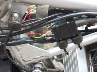
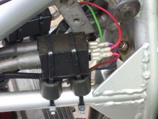
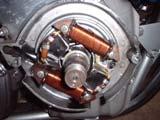
7 FIG. 1 FIG. 1a FIG. 2 FIG. 2a FIG. 3 7
8 WIRING (PLEASE SEE WIRING SCHEMATIC ON PAGE 11) 1. Take the supplied wiring harness and push the two plug connectors into the matching connectors on the ignition module until they latch; the plugs will only fit one way. If they need to be released from the module at any time, depress the latch whilst pulling on the plug. 2. From the 6-way plug, route the sleeved bi-coloured wires along and down the frame (avoiding sharp edges), then feed through the exit hole in the generator housing. 3. Taking the baseplate, fit sleeving as required over the charging coil wires. 4. Route the upper charging coil wires route around the crankcase casting above the crankshaft; route the lower charging coil wires below. Feed the charging coil wires through the exit hole in the crankcase. Route the wires up to the connector terminal block and reconnect to the original rectifier/regulator connections, which should be as follows: yellow to yellow and yellow/black to yellow/ black, from each charging coil. 5. The ignition timing sensor wires (sleeved) are coloured: white red, violet red & white black. Feed these wires (from the back of the baseplate) through the hole between the four hex spacers Cut the cable & sleeving to length. Carefully strip back approx. 4-5mm of insulation from the ends of the three wires. Connect the three wires from the sensor to the corresponding colour wires from the ignition module, as follows: WIRE COLOUR SENSOR TERMINAL White-Red LEFT (RED DOT) Violet-Red MIDDLE White-Black RIGHT (BLACK DOT) Colours must match. 6. Take the new ignition timing sensor and position on top of the four hex pillars on the baseplate, with the 3-way terminal connector block facing towards the outer edge. Secure the sensor to the pillars with the four M3 hex screws and lockwashers. Tighten the screws with a 2.5mm Allen key. Gently pull the excess wire back through the rear of the baseplate. 8
9 Important: ensure that the sensor wires are kept well within the outer edge of the baseplate, to avoid possible contact with the flywheel. These wires should form a small loop, coming from under the sensor and into the connector block. Feed any excess wire from the sensor back through the exit in the crankcase. 7. Carefully slide the newly assembled baseplate over the rotor and fit into the crankcase, making sure that the wiring on the reverse of the baseplate is not trapped between the plate and the crank casing. Fit the two fixing screws/washers, finger tighten only at this stage. 8. From the 4-way plug, route the sleeved violet, green & red wires along the frame tubing and around to the ignition coil spade terminals, avoiding sharp edges, etc. Cut the wires and sleeving to the correct length. Strip approx. 5mm of insulation from the ends of the wires, slide over insulators and crimp female spade terminals to the ends of the violet and green wires. 9. Take the short red coil link wire and push the piggyback connector onto the positive (+) terminal of ignition coil#1. Push the other end of the link wire onto the positive (+) terminal of ignition coil# Connect the VIOLET wire from the ignition module to the negative ( ) terminal of ignition coil#1, using a female crimp connector and insulating cover. Coil#1 is the dual output coil that fires cylinders 1& Connect the GREEN wire from the ignition module to the negative ( ) terminal of ignition coil#2, using a female crimp connector and insulating cover. Coil#2 is the single output coil that fires cylinder Connect the red wire from the ignition module to the +12 volts feed from ignition/kill switch. 13. Connect the other end of the red wire from the ignition coils to the +12 volts feed from ignition/kill switch. Alternatively, this wire can be connected to the battery positive (an inline 8-10A fuse can be fitted here). This second method can aid cold starting, by reducing possible volt drops in the wiring and switches. 14. Route the black wire from the ignition module directly to the battery negative ( ), using a ring terminal. Re-check the connections to the ignition coils; reverse polarity may damage the coils 9
10 15. The ORANGE wire is an ignition inhibit input. This can be connected to a grounding kill switch or a hidden security switch. If not required, place insulating tape over the end of the wire to prevent shorting out. 16. The GREY wire is a tacho output signal for driving an electronic tachometer, if fitted. This is a 12 volt pulsed output and provides 1 pulse per engine revolution (1 pulse/rev). If your tacho requires a different pulse rate, contact Pazon Ignitions. Connect to the tacho signal input terminal/wire. If you have a mechanical tacho, an inductive pickup tacho (e.g. Scitsu) or no tacho, then leave unconnected; cut short the wire & and insulate the wire end. 17. Any remaining wires which may be present on the ignition module are for factory use and should remain unconnected and insulated, as supplied. 18. Refit fuel tank. 10
11 WARNING: TURN OFF/DISCONNECT THE BATTERY BEFORE WORKING ON THE SYSTEM HIGH VOLTAGES CAN KILL NEGATIVE EARTH LAVERDA 180 WIRING WARNING: TURN OFF/DISCONNECT THE BATTERY BEFORE WORKING ON THE SYSTEM HIGH VOLTAGES CAN KILL DIGITAL IGNITION WIRING DIAGRAM FRAME EARTH / BATTERY NEGATIVE TO + 12V POSITIVE FEED FROM IGNITION SWITCH HT OUTLETS TO CYL. #2 PLUG TO CYLS. #1 & # 3 PLUGS RED BLACK IGN. COIL #2 IGN. COIL #1 VIOLET GREEN RED COIL LINK WIRE ORANGE GREY IGNITION MODULE TYPE PDL1 WHITE RED VIOLET RED WHITE BLACK IGNITION TIMING SENSOR SIGNAL TO TACHO (IF REQUIRED) TO GROUNDING KILL/STOP SWITCH (IF REQUIRED) 11
12 TIMING WARNING: RISK OF ELECTRIC SHOCK. 1. The following operations may produce a spark from the plugs, therefore it is recommend that the spark plugs be removed & grounded onto the cylinder head (with the plug caps & h.t. leads connected). Alternatively, the violet and green wires can be temporarily disconnected from the negative terminal of the ignition coils, place insulation tape over the end to prevent shorting out, etc. 2. If not already done, the engine should be positioned at the TDC mark on cylinders 1&3. 3. Turn the baseplate until the trailing edge of the large lobe on the ignition timing rotor is approximately aligned with the middle of the ignition timing sensor. See fig Switch the ignition on. The green led on the Pazon ignition module should turn ON to indicate power is on. 5. Check the red timing light on the sensor; if it is ON, goto step Rotate the baseplate clockwise until the red timing light turns ON. 7. Rotate the baseplate anti-clockwise until the red timing light turns OFF, stop turning. Tighten the two baseplate fixing screws with a 4mm Allen key. The final position will be as shown in fig Refit flywheel, washer & large nut. 9. If you wish to verify and/or fine-tune the ignition timing with a strobe timing light, proceed as follows: For accurate results when using a strobe light, we recommend using a separate battery for powering the strobe Warm the engine and, using a white light strobe, check that the engine is at the required timing mark (10 BTDC at idle, or the standard full advance mark of 5800 rpm) If so, there is no need to adjust the timing. To adjust the timing, stop the engine and rotate the baseplate a small amount on its adjustment slots To advance the timing, turn the baseplate against the rotation of the crankshaft shaft, i.e. turn the baseplate anti-clockwise To retard the timing, turn the baseplate in the same direction as the crankshaft, i.e. turn the baseplate clockwise 9. Due to improved combustion with this ignition, you may need to 12
13 adjust carburation settings for optimum tickover and performance. 10. Refit alternator cover, side panels, etc., as required. 11. Installation is now complete. MODULE FUNCTIONS The Pazon ignition module has two leds (light emitting diodes) on the front, where the wires exit. The green led functions as follows: Turns on to show a successful power-up condition of the module When the engine stops turning (with the ignition switched on) the green led will turn off & on within two seconds after the engine has stopped turning, indicating that the module has successfully reset The yellow led functions as follows: Function button pressed indicator. Flashes during setting/resetting of user programmable rev-limiter, see page 14. STATIC TIMING TDC CYLINDERS 1&3 FIG. 4 TDC REFERENCE EDGE CYLINDER 2 TDC REFERENCE EDGE CYLINDERS 1&3 13
14 REV-LIMITER USE OF THIS FUNCTION IS AT YOUR OWN RISK, SINCE IT IS POSSIBLE TO SET THE REV-LIMITER TO BEYOND THE RECOMMENDED UPPER RPM LIMIT FOR YOUR ENGINE. Note: as standard, this system has a built-in rev-limiter in the form of a sharp ignition retard commencing at 8500rpm and reaching fully retarded (5 ) at 8900rpm. To set a rev-limiter at a lower rpm, proceed as follows. The Smart-Fire ignition module features a function button that enables the user to set/reset an ignition rev-limiter. Unless specified when purchasing the system, the user rev-limiter is not preset, allowing your engine to rev to the maximum. To Set the Rev-Limiter To accurately set the rev-limiter you will need a rev-counter/tachometer to monitor the engine rpm. Rev the engine to one-half the desired rev-limit rpm, press & hold the function button for a minimum of 3 seconds. The ignition module will take a snapshot of the engine rpm at the instant the button is pressed, therefore it is not essential to maintain a precise rpm whilst the button is pressed. The yellow indicator led on the module will flash 5 times. Release the button. The rev-limiter is now set. When your engine reaches the preset rpm the ignition will turn off the ignition coil, cutting all sparks. Thus, the engine rpm will fall and, once below the rev-limit setting, ignition will resume. The minimum rev-limiter setting is 3000 rpm (i.e. set with the engine running at 1500 rpm). To Reset the Rev-Limiter To reset (disable) the ignition rev-limiter, press & hold the function button for a minimum of 3 seconds, with the engine below 1500 rpm (or stationary). The yellow indicator led on the module will flash 5 times. Release the button. The rev-limiter is now reset. The rev-limiter setting is retained in the ignition module memory & will be recalled when the ignition is turned on. 14
15 Smart-Fire Ignition Timing LAVERDA 180 TRIPLE ENGINE R.P.M. MAP026 DEGREES OF ADVANCE 15
16 Terms & Conditions and Warranty Use of this product indicates your acceptance of this notice. The product design, firmware & literature is Copyright PAZON , & is protected under international copyright, trademark & treaty provisions. To provide the best ignition systems possible, PAZON IGNITIONS reserves the right to alter & improve the specifications of its products without prior notice. Ignition Systems Pazon warrants to the original purchaser that the Pazon Ignition System be free from defects in workmanship & parts under normal use for a period of 7½ years from date of purchase. Ignition Spares Spares are defined as item(s) not purchased as part of a complete ignition system. Pazon warrants to the original purchaser that these item(s) be free from defects in workmanship & parts under normal use for a period of one year from date of purchase. Ignition coils will only be covered by the warranty if it can be proved that the fault is due to a manufacturing fault within the coil. Limitation of Liability In no event shall Pazon's liability related to the product exceed the purchase price actually paid for the product. Neither PAZON nor its suppliers shall in any event be liable for any damages whatsoever arising out of or related to the use or inability to use the product, including but not limited to the direct, indirect, special, incidental or consequential damages, or other pecuniary loss. This warranty will be void if the product or parts have been altered, damaged, abused or installed incorrectly. This warranty will be void if parts supplied by Pazon are used with other makes of ignition. Your statutory rights are not affected. Warranty Claims To make a claim under warranty, the product must be returned to PAZON or its authorized representative, with a copy of your receipt (or evidence of date & place of purchase), within the warranty period. Include a detailed description of the problem and why you believe there is a fault within the ignition system. The system must be returned postage paid. Proof of posting is not proof or receipt, therefore we recommend using a recorded mail service. Upon receipt we will thoroughly test the returned items and repair or replace any items found to be faulty and covered by the warranty. Please allow seven working days from receipt of the returned parts before contacting us, to allow sufficient time for a thorough test and evaluation. PLEASE CONTACT PAZON IGNITIONS FOR RETURN INSTRUCTIONS. 16 PAZON, 30 DOUBLEDAY DRIVE, BAPCHILD, SITTINGBOURNE, KENT ME9 9PJ U.K. TELEPHONE: +44 (0) FAX: +44 (0) ignition@pazon.com WEB: PDL1
V-TWIN HIGH-PERFORMANCE IGNITION SYSTEM 12 VOLT SYSTEM TYPE: PDV1
 Smart ー Fire V-TWIN HIGH-PERFORMANCE IGNITION SYSTEM 12 VOLT SYSTEM TYPE: PDV1 Smart-Fire APPLICATIONS VINCENT 50 DEGREE V-TWINS & SIMILAR APPLICATIONS WITH 12-VOLT ELECTRICS, POSITIVE OR NEGATIVE EARTH
Quality British Product. Electronic Ignition Systems For Classic Road & Racing Applications HIGH-PERFORMANCE IGNITION SYSTEM FOR GOLDWING GL1000
 Quality British Product SYSTEM TYPE: PDHG1 Electronic Ignition Systems For Classic Road & Racing Applications SMART ー FIRE HIGH-PERFORMANCE IGNITION SYSTEM FOR GOLDWING GL1000 PAZON : THE ULTIMATE SPARK
UNIT TWIN ATLAS TWINPLUG HEAD HIGH-PERFORMANCE IGNITION SYSTEM 12 VOLT
 Smart ー Fire UNIT TWIN ATLAS TWINPLUG HEAD HIGH-PERFORMANCE IGNITION SYSTEM 12 VOLT SYSTEM TYPE: PD2TTP Smart-Fire APPLICATIONS TRIUMPH UNIT TWIN / NORTON ATLAS TWIN WITH TWINPLUG HEAD CONVERSION 12 VOLT
UNIT TWIN 90 CRANKSHAFT HIGH-PERFORMANCE IGNITION SYSTEM 12 VOLT
 Smart ー Fire UNIT TWIN 90 CRANKSHAFT HIGH-PERFORMANCE IGNITION SYSTEM 12 VOLT SYSTEM TYPE: PD90 SMART-FIRE APPLICATIONS TRIUMPH/BSA/NORTON UNIT TWIN (ALL MODELS, INCL E-START) WITH 90 /270 CRANKSHAFT 12
MAGNETO REPLACEMENT HIGH PERFORMANCE
 Smart ー Fire MAGNETO REPLACEMENT HIGH PERFORMANCE ELECTRONIC IGNITION SYSTEM FOR 4 STROKE VELOCETTE SINGLE CYLINDER MOTORCYCLES WITH 12 VOLT ELECTRICS, POS/NEG GROUND SYSTEM TYPE: PDMSV1 Smart-Fire Applications
Altair Electronic Ignition System for
 Altair Electronic System for 3 Cylinder Motorcycles System# AL3 Altair Electronic System for Triumph Trident T150, T150V, T160 X75 Hurricane BSA A75R Rocket 3 Features Fully digital design Compact digital
MAGNETO REPLACEMENT. Pre-Unit Twin Cylinder Motorcycles. ELECTRONIC IGNITION SYSTEM For 4 Stroke. With 12 VOLT Electrics, POS/ NEG Ground
 Sure ー Fire MAGNETO REPLACEMENT ELECTRONIC IGNITION SYSTEM For 4 Stroke Pre-Unit Twin Cylinder Motorcycles With 12 VOLT Electrics, POS/ NEG Ground SYSTEM TYPE: PAMT1 2 Sure-Fire System Contents: MAGNETO
MAGNETO REPLACEMENT TWIN CYLINDER MOTORCYCLES ELECTRONIC IGNITION SYSTEM FOR 4 STROKE WITH 6 VOLT ELECTRICS, POS/ NEG EARTH SYSTEM TYPE: PAMT1-6
 Sure ー Fire MAGNETO REPLACEMENT ELECTRONIC IGNITION SYSTEM FOR 4 STROKE TWIN CYLINDER MOTORCYCLES WITH 6 VOLT ELECTRICS, POS/ NEG EARTH SYSTEM TYPE: PAMT1-6 Sure-Fire Applications BRITISH 4 STROKE TWIN
TWIN CYLINDER MOTORCYCLES WITH POINTS IN THE SIDE CASING
 Sure ー Fire ELECTRONIC FOR UNIT CONSTRUCTION TWIN CYLINDER MOTORCYCLES WITH POINTS IN THE SIDE CASING & 12 VOLT ELECTRICS POSITIVE OR NEGATIVE GROUND SYSTEM TYPE: PA2 2 Sure-Fire System Contents: MODULE
Tri-Spark - Classic Triple Trident & R3 Installation Instructions
 Tri-Spark - Classic Triple Trident & R3 Installation Instructions TRI-0002 Copyright Tri-Spark 2015 Revised June 2015 Thank you for purchasing the Tri-Spark Classic Triple Ignition system. For your own
Tri-Spark Ignition System Installation Triple Cylinder TRI-0001
 Tri-Spark Ignition System Installation Triple Cylinder TRI-0001 There are potentially lethal high voltages produced at the ignition coils and spark plugs, therefore every precaution must be taken to prevent
AccuSpark. Fitting and Information Guide For. Modules Distributors coils Tools. Modern Ignition for Classic cars
 AccuSpark Modern Ignition for Classic cars Fitting and Information Guide For Modules Distributors coils Tools www.accuspark.co.uk 1 Before fitting AccuSpark Distributors AccuSpark electronic ignition kit.
STK-010 BSA: B25, B40, B44, B50, C15, Royal Enfield Bullet
 STK-010 BSA: B25, B40, B44, B50, C15, Royal Enfield Bullet Stator ST-010 HT-CDI Kill switch Rotor IR10 Fitting Kit Collet Self generating CDI Ignition with electronic advance, developed for BSA singles,
To avoid a short cut please file off the right half of the Y-hole flange.
 Fitting instructions for automatic alternator controller for Moto Guzzi with Bosch alternator 1. alternator modification - 2. Fitting - 3. adjustment (ignition only) First remove the connector block of
CAUTION: READ INSTRUCTIONS CAREFULLY BEFORE STARTING INSTALLATION
 V-Twin MFG. VT No. 32-9500 V-TECH 1 IGNITION KIT, SINGLE FIRE FITS EV SHOVEL, XL THRU 1997 VT No. 32-9503 V-TECH 1 IGNITION KIT, SINGLE FIRE FITS EV, SHOVEL, XL, WITH COIL AND WIRES This is a custom application
SCHNITZ MOTORSPORTS USER MANUAL AND INSTALLATION GUIDE PRO-MOD BATTERY VOLTS DIAGNOSTICS NOS PULSE FREQUENCY NOS DELAY TIME IN SECONDS
 SCHNITZ MOTORSPORTS DSC-CS "PRO-MOD" IGNITION CONTROLLER USER MANUAL AND INSTALLATION GUIDE COIL, (OPTIONAL) GA YELLOW, COIL, NEGATIVE GA WHITE, GA BLACK, SHIFT LIGHT +V OUTPUT PAGE 0 NOS ACTIVATION INPUT
INSTALLATION INSTRUCTIONS for HI-4 DUAL FIRE MOTORCYCLE IGNITION. Part Number INTRODUCTION REMOVAL OF POINTS IGNITION TO 1977 MODELS
 INSTALLATION INSTRUCTIONS for HI- DUAL FIRE MOTORCYCLE IGNITION Part Number -00 CAUTION: READ INSTRUCTIONS CAREFULLY BEFORE STARTING INSTALLATION INTRODUCTION The HI- ignition system is intended for use
Chapter 5 Part B: Ignition system - transistorised type
 5B 1 Chapter 5 Part B: Ignition system - transistorised type Contents Coil - testing........................................... 9 Distributor - overhaul..................................... 7 Distributor
USER MANUAL AND INSTALLATION GUIDE ENGINE RPM AND NOS SHIFT COUNTER NOS DELAY TIME IN SECONDS NOS START PERCENT NOS FINAL PERCENT
 SCHNITZ MOTORSPORTS DSC-9PS "PRO-STREET" IGNITION CONTROLLER USER MANUAL AND INSTALLATION GUIDE SHIFT LIGHT POSITIVE PAGE 2 SHIFT LIGHT GROUND PAGE 2 NOS SOLENOID GROUND 1GA ORANGE, FUEL SOLENOID GROUND
MSD Single Cylinder Programmable Ignition PN 4217
 MSD Single Cylinder Programmable Ignition PN 4217 Parts Included: 1 - PN 4217 1 - PN 4217 Wire Harness 1 - CD Rom 9609 1 - Parts Bag 1 - Serial Cable WARNING: During installation, disconnect the battery
PVL Racing Ignition Installation Instructions
 PVL Racing Ignition Installation Instructions Fit the ignition coil together with the core sheet package to the chassis frame; additionally, silent blocks may be used to absorb vehicle vibrations and shocks.
INSTALLATION INSTRUCTIONS
 INSTALLATION INSTRUCTIONS www.factorydirectperf.com Made exclusively for FDP by SEA-DOO 800 Enhancer Ignition, PN 30-08-2630 Fits SEA-DOO XP, GSX, GTX Watercraft w/rave Engine IMPORTANT: Read these instructions
USER MANUAL AND INSTALLATION GUIDE TIMER DELAY IN SECONDS SHIFT STYLE & SHIFT COUNTER TIMER DURATION NOS DELAY TIME IN SECONDS NOS START PERCENT
 SCHNITZ MOTORSPORTS DSC-TG0- "TOP-GAS " IGNITION CONTROLLER USER MANUAL AND INSTALLATION GUIDE COIL, (OPTIONAL) GA YELLOW, PAGE COIL, NEGATIVE GA WHITE, PAGE SHIFT LIGHT GROUND 0GA BROWN, PAGE 0 SHIFT
1 Function Scope of Delivery Mounting Electrical Connections Initial Setup Troubleshooting...
 Elektronik Sachse MHP GmbH & Co. KG Installation Manual Digital Ignition ZDG 3.23 (Ducati Mille) Item: Z73 version: f4feb00 Contents 1 Function.......................................................................
Tri-Spark - Classic Twin Installation Instructions
 Tri-Spark - Classic Twin Installation Instructions Revised Jan 2013 Thank you for purchasing a Tri-Spark Classic Twin Ignition system for your Classic bike. For your own safety and success with the installation
INSTALLATION INSTRUCTIONS for HI-1 and HI-2 MOTORCYCLE IGNITIONS. Part Numbers and INTRODUCTION COIL AND SPARK PLUG CABLE CONSIDERATIONS
 INSTALLATION INSTRUCTIONS for HI- and HI- MOTORCYCLE S Part Numbers 8-000 and 8-000 CAUTION: READ INSTRUCTIONS CAREFULLY BEFORE STARTING INSTALLATION INTRODUCTION Crane HI- and HI- ignition systems are
470nF REG1 LM2940. VR3 100k 10k VR1 100 F. 470pF. 100nF. 100nF RELUCTOR Q2 BC k. 10k TP GND. 2.2nF TO RELUCTOR. 470nF REG1 LM2940 REG1 LM2940
 Where to buy kits Jaycar and Altronics have full kits (including the case) available for the High Energy Electronic Ignition System. The Jaycar kit is Cat. KC-5513 while the Altronics kit is Cat. K4030
MSD-8 Plus Ignition PN 7805
 MSD-8 Plus Ignition PN 7805 Note: Solid Core spark plug wires cannot be used with an MSD Ignition. Parts Included: 1 - MSD-8 Plus Ignition 1 - Mag Pickup Extension Harness, PN 8860 4 - Vibration Mounts
Turn Signal Kit Installation Instructions for Model A Fords & Other Antique Vehicles
 Turn Signal Kit Installation Instructions for Model A Fords & Other Antique Vehicles Lifetime Technical Support support@logolites.com 770-476-7322 www.logolites.com Manual 100-0005N Thank you for purchasing
MSD Circle Track Ignition PN 6427
 MSD Circle Track Ignition PN 6427 ONLINE PRODUCT REGISTRATION: Register your MSD product online. Registering your product will help if there is ever a warranty issue with your product and helps the MSD
3M Cold Shrink QT-III Silicone Rubber Three-Core Termination Kits
 3M Cold Shrink QT-III Silicone Rubber Three-Core Termination Kits With High-K Stress Relief For 3-Conductor Type G (Ground Wire), Copper Tape Shield, Armored Cables 7600-S-3G Series Instructions IEEE Std.
Shelbourne header monitor kit Up to 2004
 Shelbourne header monitor kit Up to 2004 The Shelboume Header Monitor monitors and displays the running speeds of the Stripping Rotor and the Auger of the combine header. The speed of either can be displayed
STREET/RACE DISTRIBUTOR
 Installation Instructions for STREET/RACE DISTRIBUTOR CAUTION: READ INSTRUCTIONS CAREFULLY BEFORE STARTING INSTALLATION INTRODUCTION The Crane Cams street/race distributor is a high precision system intended
3M Cold Shrink Silicone Rubber Termination QT-III 7600-S-3G Series Three-Core Outdoor Termination
 3M Cold Shrink Silicone Rubber Termination QT-III 7600-S-3G Series Three-Core Outdoor Termination Instructions IEEE Std. No. 48 Class 1 Termination CAUTION Working around energized electrical systems may
Installing Ignition Coil relay
 Installing Ignition Coil relay Above is a schematic diagram of the coil relay modification. All it really does is, it uses the existing 12 Volt positive that normally powers the coils, to power a relay,
ACCEL Distributor Model #A557
 FORM 1627 REV1 INSTALLATION INSTRUCTIONS ACCEL Distributor Model #A557 CAUTION: CAREFULLY READ INSTRUCTIONS BEFORE PROCEEDING. NOT LEGAL FOR USE OR SALE ON POLLUTION CONTROLLED VECHICLES OVERVIEW ACCEL
OFF-ROAD ELECTRONIC IGNITION CONTROL
 INSTALLATION INSTRUCTIONS FORM 1678M 05/07 OFF-ROAD ELECTRONIC IGNITION CONTROL GENERAL INFORMATION This ignition includes a single stage RPM limiter. You can set various settings using the switches that
Installation Instructions PowerBoard Automatic Retracting Running Board
 Installation Instructions PowerBoard Automatic Retracting Running Board Vehicle Application Chevy Silverado/GMC Sierra Extended Cab 2007 and newer (excluding 2011 Diesels) Part Number: 75123-15 Chevy Silverado/GMC
Ford 6.7L Installation of the Guardian Safety System
 Ford 6.7L Installation of the Guardian Safety System Diesel Tech Industries Ltd. 14215-120 Avenue Edmonton, Alberta, Canada T5L 2R8 Phone: (780) 455-9876 info@dtiguardian.com www.dtiguardian.com DTI05-02.01/13
INSTALLATION INSTRUCTIONS
 THANK YOU FOR CHOOSING KURYAKYN! Protect yourself and others from possible injury and property damage or loss. Pay close attention to all instructions, warnings, cautions, and notices regarding the installation,
Installation Instructions PowerBoard Automatic Retracting Running Board
 Installation Instructions PowerBoard Automatic Retracting Running Board Vehicle Application Chevy Silverado/GMC Sierra Extended Cab Diesel 2011 and newer Part Number: 75147-15 Chevy Silverado/GMC Sierra
MSD-8 Plus Ignition PN 7805
 MSD-8 Plus Ignition PN 7805 ONLINE PRODUCT REGISTRATION: Register your MSD product online. Registering your product will help if there is ever a warranty issue with your product and helps the MSD R&D team
C FORD F250 / F L POWERSTROKE DIESEL WITH AUTOMATIC TRANSMISSIONS ONLY
 EXHAUST BRAKES C40019 1999-2003 FORD F250 / F350 7.3L POWERSTROKE DIESEL WITH AUTOMATIC TRANSMISSIONS ONLY Getting Started Thank you and congratulations on your purchase of a Pacbrake exhaust retarder.
MOTORIZED FOLDING CAMPER WINCH
 OWNER'S MANUAL MOTORIZED FOLDING CAMPER WINCH With 1200lb Lift Capacity The 12 Volt Motorized Folding Camper Winch is used to raise and lower folding campers with the touch of the switch, eliminating hand
This LED flashtube kit covers models 400, 404, 500, 504, 600, 680 & 506.
 L.E.D. INSTRUCTIONS I D T S O T U B I R M O C R Y N A P Kit contains: This LED flashtube kit covers models 400, 404, 500, 504, 600, 680 & 506. For the power supply: 1-LED power supply circuit board, 2
PIL0478 ISSUE 01/ 07/16
 ISSUE 01/ 07/16 PIL0478 ZAFIR G9 CEILING FITTING PIL0478 ISSUE 01/ 07/16 PART C PART E PART 21 SELV 1 1.B 1 3.1 3.3 3.4 3.5 3.6, 3.8 3.10 3.12 3.14 3.16 3.17 3.18 3.19 3.19 ATTENTION! THE TABLE BELOW
MSD 7AL-3, Ignition Control PN 7230
 MSD 7AL-3, Ignition Control PN 7230 Important: Read the instructions before attempting the installation. Parts Included: 1-7AL-3, PN 7230 1 - Parts bag (wires and connectors) 4 - RPM Modules 3000, 7000,
MSD Stacker-4 (4-Channel), PN 7010 Stacker-8 (8-Channel), PN 7020
, PN 7010 Stacker-8 (8-Channel), PN 7020") INSTALLATION INSTRUCTIONS 1 MSD Stacker-4 (4-Channel), PN 7010 Stacker-8 (8-Channel), PN 7020 Important: Read these instructions before attempting this installation! Parts Included: 1 - MSD Stacker Ignition
INSTALLATION INSTRUCTIONS 1 MSD Stacker-4 (4-Channel), PN 7010 Stacker-8 (8-Channel), PN 7020 Important: Read these instructions before attempting this installation! Parts Included: 1 - MSD Stacker Ignition
MSD Marine Ignitions 6M-2L, PN 6560
 MSD Marine Ignitions 6M-2L, PN 6560 ONLINE PRODUCT REGISTRATION: Register your MSD product online. Registering your product will help if there is ever a warranty issue with your product and helps the MSD
FK75 / FK95 Quick Installation Guide
 FK75 / FK95 Quick Installation Guide Battery - Pin 1 2 3 4 5 6 7 Fan Potentiometer 9 10 11 Battery + Fan + Setting the Temperature The controller is set from the factory for use with a 10 degree thermostat,
1 Function Scope of Delivery Mounting Electrical Connections Initial Setup Troubleshooting...
 SACHSE Elektronik Sachse MHP GmbH & Co. KG Installation Manual Digital Ignition ZDG 3.23 (Honda CB72/ 77) Item: Z06-CB72 version: 62aa227 Contents 1 Function.......................................................................
Installation Instructions PowerBoard Automatic Retracting Running Board
 Installation Instructions PowerBoard Automatic Retracting Running Board Vehicle Application Dodge Ram 1500 Crew Cab 2009 - Current : 75138-15 Dodge Ram 2500/3500 & HD Crew Cab 2010 - Current : 75138-15
MSD Blaster Ignition PN 5900
 MSD Blaster Ignition PN 5900 Note: Read these instructions completely before attempting any installation. Parts Included: 1 - Blaster Ignition, PN 5900 1 - Harness, PN 8860 1 - Harness, PN 8861 1-18" Ground
MSD Digital 6M-3L Marine Ignition PN 6564
 MSD Digital 6M-3L Marine Ignition PN 6564 ONLINE PRODUCT REGISTRATION: Register your MSD product online. Registering your product will help if there is ever a warranty issue with your product and helps
Your G3 buggy is fitted with three switches on the front part of the body:
 CONTENTS Buggy operation... 3 General Maintenance... 5 Technical Maintenance... 6 Front wheel bearing replacement... 6 Rear wheel bearing replacement... 7 Chain replacement... 8 Chain Adjustment... 9 Brake
Alpha Performance Ignition Management Kit Fitting Instructions. Kit K Ford Zetec 1800cc 16 Valve & Ford Zetec 2000cc 16 Valve
 Alpha Performance Ignition Management Kit Fitting Instructions Kit K97017 Ford Zetec 1800cc 16 Valve & Ford Zetec 2000cc 16 Valve For further information, please contact: Webcon UK Ltd Dolphin Road Middlesex
Installation Instructions PowerBoard Automatic Retracting Running Board
 Installation Instructions PowerBoard Automatic Retracting Running Board Vehicle Application Chevy Silverado/GMC Sierra Extended Cab 2007 and newer (excluding 2011 Diesels) Part Number: 75123-15 Chevy Silverado/GMC
DLKEK3HN INSTALLATION INSTRUCTIONS
 DLKEK3HN INDEX: INSTALLATION INSTRUCTIONS WIRING INSTRUCTIONS... PG 2-5 LED STATUS INDICATOR... PG 6 VALET/OVERRIDE BUTTON... PG 6 SHOCK SENSOR... PG 7 PROGRAMMABLE JUMPER-PINS... PG 7 PROGRAMMING REMOTE
Southwest Windpower Instruction Sheet AIR-X Circuit Replacement Kit
 Southwest Windpower Instruction Sheet AIR-X Circuit Replacement Kit Tools Required 5 / 32 Hex key 5 / 16 Hex key 7 / 64 Hex key Standard screwdriver Pair of external snap ring pliers Rubber mallet Hammer
Installation Guide for the Electronic Ignition Distributor
 Installation Guide for the Electronic Ignition Distributor Remanufactured By East Coast Roadster East Coast Roadster: Ignition systems and accessories for Datsun Roadster fanatics! PLEASE, Call with any
5. Refer to GTR Workshop Manual, section: and disconnect battery ground cable.
 HYDRAULIC HOSE REPAIR REMOVAL PROCEDURE 1. Open door. 2. Turn ignition 'ON'. 3. Power the convertible top to the fully lowered position. 4. Turn ignition 'OFF'. 5. Refer to GTR Workshop Manual, section:
Mounting instructions for the '123ignition'
 Mounting instructions for the '123ignition' type : 123\GB-4-R-V for : most English 4 cylinder engines, 6 & 12 Volt, negative earth only! IMPORTANT Please read the entire instructions before you begin installation.
PLEASE READ BEFORE CALLING OR RETURNING PRODUCT. EXTREMELY IMPORTANT!!!
 Thank you for your purchase of WeaponX Smart Direct Fire Ignition Coil System for your vehicle. The following are the instruction manuals for your ignition system kit. Please read carefully and enjoy your
INSTALLATION INSTRUCTIONS
 INSTALLATION INSTRUCTIONS FRM34418 (REV. B) 09/17 UNILITE DISTRIBUTOR This product is applicabl e to pre-1966 California and pre-1968 federally certified passenger cars. It is also applicable to non-emission
NEXUS. Introduction SENSOR MODULE &
 2650-1056 INSTALLA AT TION INSTRUCTIONS NEXUS SENSOR MODULE & REMOTE ASSEMBLY IMPORTANT WEAR SAFETY GLASSES 60 80 40 100 FUEL 20 PSI 0 AUTO METER PRODUCTS INC. c 2004-6463 0 10 20 10 20 BOOST VAC In.Hg
MSD 7AL-2 Plus Ignition PN 7222
 MSD 7AL-2 Plus Ignition PN 7222 Note: Solid Core spark plug wires cannot be used with an MSD Ignition. Note: An MSD cannot be used on vehicles with CD ignitions or distributorless ignition systems. Parts
MSD Pulse Ignition for Harley-Davidson PN 42211
 MSD Pulse Ignition for Harley-Davidson PN 42211 IMPORTANT: Read these instructions before attempting the installation! It is also recommended to have your bike s Service Manual available during the installation.
INSTALLATION MANUAL DIS4-009 DISTRIBUTORLESS IGNITION SYSTEM FOR ALL A/C VWs USING BOSCH 009 DISTRIBUTOR
 INSTALLATION MANUAL DIS4-009 DISTRIBUTORLESS IGNITION SYSTEM FOR ALL A/C VWs USING BOSCH 009 DISTRIBUTOR TABLE OF CONTENTS INTRODUCTION... 2 GENERAL COMMENTS... 3 REMOVE STOCK COMPONENTS... 3 FIGURES...
ASNU Battleship MK2 Fitting Instructions
 ASNU Battleship MK2 Fitting Instructions You will be required to disassemble certain parts from the stock fuel system and then integrate them into the battleship before reinstalling the system into the
FITTING INSTRUCTIONS
 FITTING INSTRUCTIONS Read carefully all sections before proceeding with any fitting OPTRONIC CLASSIC COLLECTION PMC 50 Requires FK fitting kit sold separately Thank you for purchasing this Lumenition Ignition
Lumenition Optronic Ignition System PMA 50 Power Module. Fitting Instructions
 Not for use on low-resistance electronic coils. Fitting Instructions Read carefully all sections before proceeding with any fitting. How It Works Lumenition Optronic Ignition is an electronic ignition
SECTION M. ELECTRICAL. Section Description Page No.
 SECTION M. ELECTRICAL. Section Description Page No. M.1 General Page 2 M.2 Alternator Page 2 M.3 Battery Page 7 M.4 Hazard Warning System Page 7 M.5 Brake Fail Warning System Page 8 M.6 Seat Belt Warning
AIR CONTROL ACCESSORY KIT
 RAPID RESPONSE SYSTEM 2283 AIR CONTROL ACCESSORY KIT INSTALLATION INSTRUCTIONS Congratulations on your purchase of a new Air Control Accessory Kit. This kit was designed to provide inflation control of
STROMBERG e-fire OWNER S MANUAL MODELS 11A/21A
 STROMBERG e-fire OWNER S MANUAL MODELS 11A/21A THANK YOU for choosing a Genuine Stromberg e-fire Electronic Distributor for your Flathead Ford. This Owner s Manual will make installation and adjustment
Page 1 of 4 Model: BTL4E-004 V2.0 Pulsar Electronic LED Turn Signal Flasher Unit Installation & Operation Instructions:
 Page 1 of 4 Thank you for choosing the Bulbsthatlast4ever Model BLT4E-004 Pulsar Electronic LED Turn Signal Flasher Unit. This unit has been designed for 12-14 VDC operation with either Positive or Negative
Contents INTRODUCTION... 2 CHECK YOU HAVE RECEIVED... 4 WHAT YOU WILL NEED...4 TECHNICAL CHARACTERISTICS...5 WIRING DIAGRAMES...6 CABLES...
 Contents Page INTRODUCTION... 2 CHECK YOU HAVE RECEIVED... 4 WHAT YOU WILL NEED...4 TECHNICAL CHARACTERISTICS...5 WIRING DIAGRAMES...6 CABLES...6 BATTERY...7 CHARGE CONTROLLER...8 FUSE...8 TOWERS...8 INSTALLATIONS...9
Model A Turn Signal Kit Installation Guide
 Model A Turn Signal Kit Installation Guide Creative Connections, Inc. Consumer Hot Line: 888-471-LOGO 770-476-7322 In Atlanta, GA http://www.logolites.com P/N: 100-005/K 2008 Creative Connections, Inc.
Timer. TipTop Timers. Installation and Operation Manual
 TipTop s E TM Installation and Operation Manual Sold by: TipTop s LLC 2225 North Dollar Road Spokane Valley, WA 99212 web: Model T Electronic - E E Conversion Kit Contents The Electronic conversion kit
WORK INSTRUCTION READ FIRST. IF IN DOUBT
 WORK INSTRUCTION PAGE 1 OF 9 FIELD CHANGE INSTRUCTION : TO CHANGE A BACK DOOR AND SIDE LIFT PROCEDURE: Step 1. How to remove and replace the rear door of a canopy. Step 2. How to remove the side lift up
INSTALLATION GUIDE Table of Contents
 CT-3100 Automatic transmission remote engine starter systems. What s included..2 INSTALLATION GUIDE Table of Contents Door lock toggle mode..... 4 Notice...2 Installation points to remember. 2 Features..2
Toggle Button Kit. Installation Instructions
 Toggle Button Kit Installation Instructions Thank you for choosing the Double Apex Toggle Button kit. If you have any questions about the installation please do not hesitate to email us at support@doubleapex.co.
I N S TA L L AT I O N
 I N S TA L L AT I O N 5008 fits: H-D: '80-Up Electra glide, tour glide, road king, road glide or street glide PartS Included 1 Right Fork Mount Assembly 1 Left Fork Mount Assembly 2 H3 Driving Light Assemblies
CPi. CoiL PACK IGNiTioN FOR AViATiON. For 4,6 and 8 cylinder 4 stroke applications. Please read the entire manual before beginning installation.
 1 CPi CoiL PACK IGNiTioN FOR AViATiON Coil pack (4 cylinder) Coil pack (6 cylinder) For 4,6 and 8 cylinder 4 stroke applications. Please read the entire manual before beginning installation. Software version
Manual Installation & Operation
 Manual Installation & Operation Model: NCxxLxx 12A or 30A Solid State Solar Charging Regulator and 12A Load Controller. 231 Patent #: 5,642,030 Applies Page 1 Warnings When Installing, connect grounds,
CAUTION: CAREFULLY READ INSTRUCTIONS BEFORE PROCEEDING.
 Twin Tec Installation Instructions for Ignition CAUTION: CAREFULLY READ INSTRUCTIONS BEFORE PROCEEDING. OVERVIEW Twin Tec ignition is states street legal (ARB E.O. No. D--) for use with the following Harley-Davidson
PERTRONIX DIGITAL HP INSTALLATION INSTRUCTIONS
 PERTRONIX DIGITAL HP INSTALLATION INSTRUCTIONS TABLE OF CONTENTS Specifications... 4 General Information... 5 Coil Compatibility... 6 Mounting the Digital HP... 7 Wiring... 8 User Interface... 12 Programming...
VW/AUDI MK7 VEHICLES
 Installation Manual P/N 1-301-1708-01 (STAGE 2+ FUEL KIT) P/N 1-301-1708-02 (STAGE 3+ FUEL KIT) VW/AUDI MK7 VEHICLES Warning: This installation is not recommended for a novice or the new guy in the shop.
Eazipole Cordless. Installation & Set Up Instructions. Electric Blinds & Curtains
 Eazipole Cordless Installation & Set Up Instructions Electric Blinds & Curtains Pole Installation - Deciding The Best Position Points to consider when planning the installation of your pole It may be easiest
HALOGEN FLOODLIGHTS Models CHL1260C & 1260T Part Nos: &
 HALOGEN FLOODLIGHTS Models CHL1260C & 1260T Part Nos: 5460600 & 5460595 OPERATING & MAINTENANCE INSTRUCTIONS GC0610 INTRODUCTION Thank you for purchasing this CLARKE Halogen Floodlight. Before attempting
Track Rocker Installation Instructions
 Track Rocker Installation Instructions For Installing Painless Part Numbers: 58103: 8-Switch Customizable Track Rocker Switch Panel w/ Flanged Mount 58106: 6-Switch Customizable Track Rocker Switch Panel
USB Charge Port Installation Instructions
 USB Charge Port Installation Instructions Lifetime Technical Support support@logolites.com 770-476-7322 www.logolites.com Manual 100-0014C Thank you for purchasing a Logo Lites USB Charge Port! USB Charge
PIMP Ford 5.0 Harness Installation Manual. Part Number: PM-75
 PIMP Ford 5.0 Harness Installation Manual Part Number: PM-75 Ron Francis Wiring 200 Keystone Rd Suite 1 Chester, PA 19013 800-292-1940 www.ronfrancis.com Pre-Installation Notes: This system is designed
English. Fitting Instructions: Street Triple Rx, Street Triple from VIN and Street Triple R from VIN A , A and A
 English Fitting Instructions: Street Triple Rx, Street Triple from VIN 560477 and Street Triple R from VIN 560477 A968090, A968 and A9687 Thank you for choosing this Triumph genuine accessory kit. This
Installation Instructions PowerBoard Automatic Retracting Running Board
 Installation Instructions PowerBoard Automatic Retracting Running Board Vehicle Application Ford F150 Super Crew Cab 2009 Current : 75141-15 www.bestop.com - We re here to help! Visit our web site and
VT Commodore LPG installation utilising an LPG Memcal and Apexus Quick-kit.
 VT Commodore LPG installation utilising an LPG Memcal and Apexus Quick-kit. Description of components and operation LPG/Petrol Changeover switch The LPG change-over switch is mounted in the instrument
Toggle Button Kit. Installation Instructions MK5 / MK6 Golf, MK5 Jetta
 Toggle Button Kit Installation Instructions MK5 / MK6 Golf, MK5 Jetta Thank you for choosing the Double Apex Toggle Button kit. If you have any questions about the installation please do not hesitate to
Chapter 5 Part B: Ignition system
 5B 1 Chapter 5 Part B: Ignition system Contents Distributor - removal and refitting.............................4 Ignition HT coil(s) - removal, testing and refitting.................3 Ignition system
Part Number DP6003 Chevy Truck Digital Dash YEARS 67-72
 Part Number DP6003 Chevy Truck Digital Dash YEARS 67-72 KIT COMPONENTS: One (1) Digital Circuit Board One (1) Smoked Acrylic See-Through Lens *Peel off protective covering from both sides of lens attached
INSTALLATION INSTRUCTIONS
 INSTALLATION INSTRUCTIONS WARNING: WARNING: www.altronicinc.com DEVIATION DEVIATION FROM THESE FROM INSTRUCTIONS THESE INSTRUCTIONS MAY LEAD MAY TO LEAD IMPROPER TO IMPROPER OP- ERATION OF ENGINE THE MACHINE
PLEASE READ THESE INSTRUCTIONS CAREFULLY BEFORE BEGINNING INSTALLATION. FAILURE TO COMPLY MAY VOID DAVIES, CRAIG WARRANTY.
 PTY. DAVIES, CRAIG LTD. A.B.N. 71 004 918 825 A.C.N. 004 918 825 MELBOURNE AUSTRALIA 77 Taras Avenue P.O. Box 363 Altona North, Vic 3025 Australia Phone: +61(0)3 9369 1234 Fax: +61(0)3 9369 3456 E-mail: