Crop Link Pro/Lite Flowmeter Wiring Manual
|
|
|
- Aron Bradford
- 6 years ago
- Views:
Transcription
1 Crop Link Pro/Lite Flowmeter Wiring Manual Revised January 1, 2018
2 Items Covered In This Manual: Page 1: Crop Link Pro/Lite Device Overview Page 2: Netafim/Dwyer Mechanical Flow Meter Wiring Page 3: Netafim Octave Flow Meter Wiring Page 4: GF Signet Open Collector Flow Meter Wiring Page 5-9: GF Signet 8550 Flow Transmitter Wiring Page 10: McCrometer Mechanical Flow Meter Wiring Page 11-12: Seametrics AG2000, AG3000/Valley Flow Meter Wiring Page13-14: Endress Hauser Promag P 50/53 Flow Meters Page 15-16: Siemens MAG5000 Flow Meters Page 17-19: Seametrics PE102/FT520 Flow Meter Wiring Page 20-22: GF Signet 9900 Flow Transmitter Wiring Page 23-24: GF Signet 2551 Mag Meter Wiring Page 25: McCrometer FlowCom Flow Meter Wiring Page 26-27: McCrometer McMag 3000 / EA-618 Flow Meter Wiring Page 28-29: Siemens Sitrans FM MAG 8000 Wiring Page 30-32: Greyline AVFM 5.0 Flow Meter Wiring Page 33-34: Senninger Flow Wise SC-3 Flow Meter Wiring Page Banjo MFM300DC Flow Meter Wiring Page Seametrics FT415 Flow Meter Wiring Page Sparling Tiger Mag Flow Meter Wiring Page 42 Sparling FT194 Flow Meter Wiring Page 43 Generic Flow Meter Wiring Page 44: Power and Relay Wiring

3 General Overview of the Crop Link Pro/Lite Unit Page 1
4 Wire Connections for the Netafim/Dwyer Mechanical Flow Meter (two wire magnetic reed-switch style) 1. Install the Black Wire from the Netafim/Dwyer Flow Meter into any terminal marked GND as shown in the picture above. 2. Install the Red Wire from the Netafim/Dwyer Flow Meter into the terminal marked DIGITAL 1 as shown in the picture above. 3. Proceed to Page 44 of this manual for power wire connections. Page 2
5 Wire Connections for the Netafim Octave Flow Meter (with pulse or relay output module) 1. Install the Black Wire from the Netafim Flow Meter into any terminal marked GND as shown in the picture above. 2. Install the Red Wire from the Netafim Flow Meter into the terminal marked DIGITAL 1 as shown in the picture above. 3. Cut off and/or tape off the Green Wire from the Netafim Flow meter so that it cannot touch anything. 4. The label on the inside of the Netafim Flow Meter lid will show how many gallons per pulse that output1 (the red wire) is programmed to do. You will need that info when configuring this unit on Wagnet. 5. Proceed to Page 44 of this manual for power wire connections. Page 3
6 Wire Connections for the GF Signet/Senniger Open Collector Type Flow Meters Note: The flow meter must be an Open Collector type output. ( For example, models:ag Rotor , 2507 mini , 2000 micro flow meters) 1. Install the Black Wire from the GF Signet Flow Meter into the terminal marked 5v OUT as shown in the picture above. 2. Install the White/Bare Wire from the GF Signet Flow Meter into any terminal marked GND as shown in the picture above. 3. Install the Red Wire from the GF Signet Flow Meter into the terminal marked DIGITAL 1 as shown in the picture above. 4. Proceed to Page 44 of this manual for power wire connections. Page 4
7 Wire Connections for the GF Signet/Senniger 8550 Flow Transmitter 1. Install the Power Supply, and Flow Meter wires into the GF Signet 8550 Unit as shown above. 2. Install a Red wire into terminal 5 (output+) of the 8550 Unit as shown above. This wire will connect to the AgSense unit in the steps below. 3. Install a Black wire into terminal 6 (output-) of the 8550 Unit as shown above. This wire will connect to the AgSense unit in the steps below. Page 5
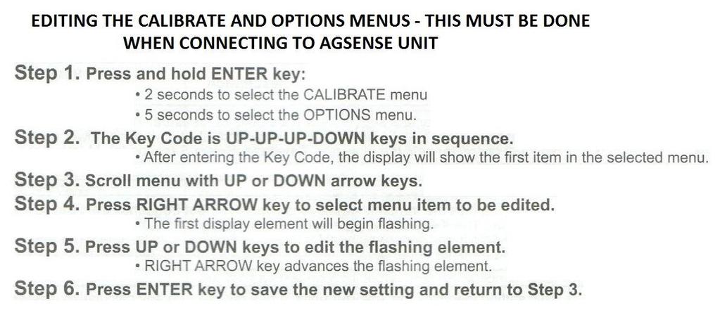
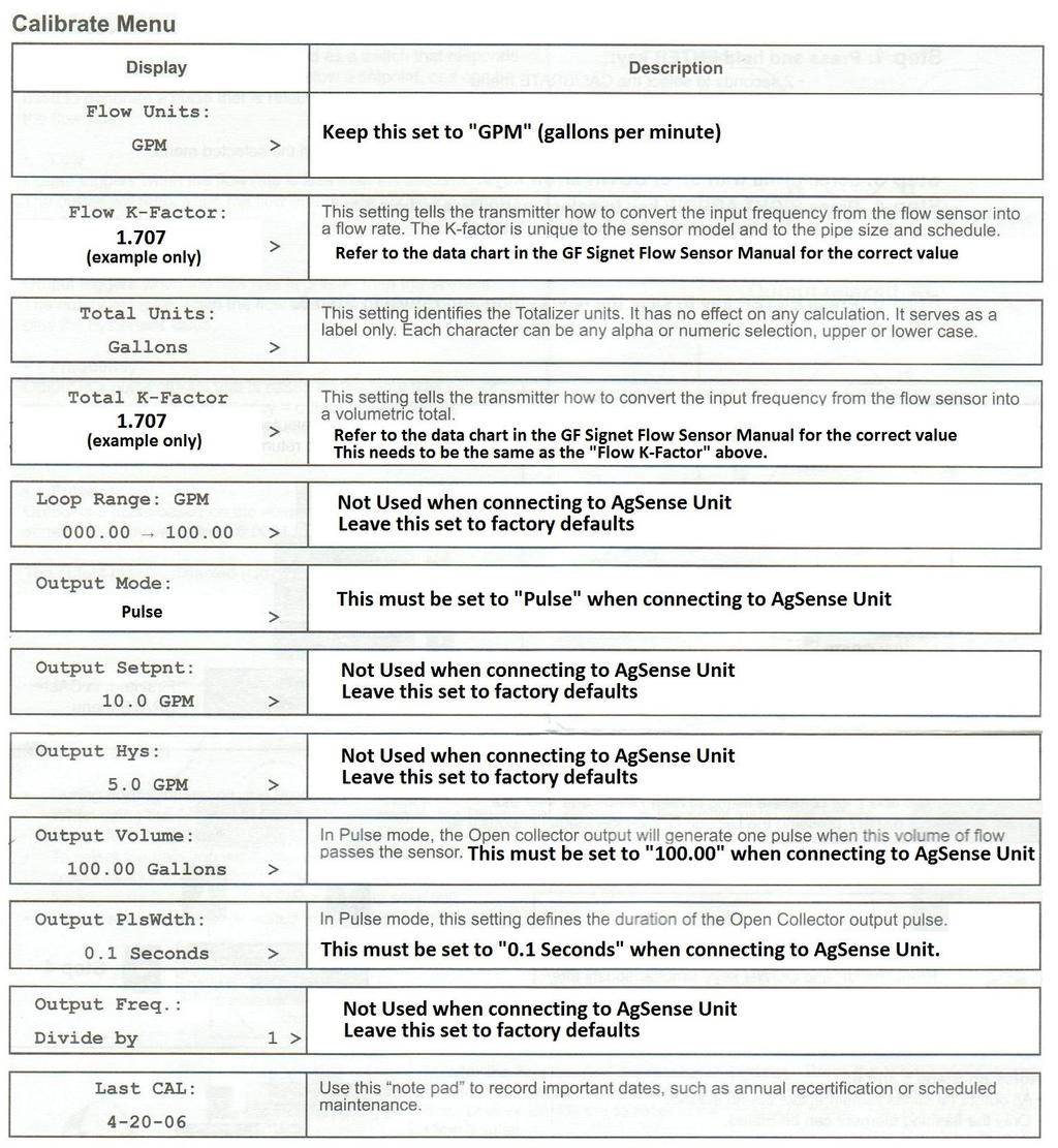
8 Wire Connections for the GF Signet/Senniger 8550 Flow Transmitter 1. Install the Black Wire from the GF Signet 8550 Flow Transmitter into any terminal marked GND as shown in the picture above. 2. Install the Red Wire from the GF Signet 8550 Flow Transmitter into the terminal marked DIGITAL 1 as shown in the picture above. 3. Setting up the 8550 Flow Transmitter calibrate and options menus use the charts below to correctly set up the menus in the 8550 Flow Transmitter you must do this for the AgSense unit to work properly. Page 6
9 Page 7
10 Page 8
11 Once these settings are all changed, proceed to page 44 for AgSense Unit power connections. Page 9

12 Wire Connections for the McCrometer Mechanical Flow Meter with EA-631-xxx module 1. Install the Red Wire from the McCrometer Flow Meter into the terminal marked 12v OUT as shown in the picture above. 2. Install the Black Wire from the McCrometer Flow Meter into any terminal marked GND as shown in the picture above. 3. Install the Orange Wire from the McCrometer Flow Meter into the terminal marked DIGITAL 1 as shown in the picture above. 4. Proceed to Page 44 of this manual for power wire connections. Page 10
 be sure to choose the correct version (HF or LF) in the AgSense unit configuration.")
13 Wire Connections for the Seametrics AG2000 Flow Meter Note: The Seametrics AG2000 can come programmed for High-Frequency pulses or Standard Low Frequency Scaled Pulse Output (10 or 100 gallons per pulse) be sure to choose the correct version (HF or LF) in the AgSense unit configuration. See next page for Crop Link wiring instructions Page 11
14 Seametrics AG2000, AG3000/Valley Crop Link Wiring 1. Install the Red Wire from the Seametrics Flow Meter into the terminal marked 12v OUT as shown in the picture above. 2. Install the Black Wire from the Seametrics Flow Meter into any terminal marked GND as shown in the picture above. 3. Install the White Wire from the Seametrics Flow Meter into any terminal marked GND as shown in the picture above. 4. Install the Green Wire from the Seametrics Flow Meter into the terminal marked DIGITAL 1 as shown in the picture above. 5. Proceed to Page 44 of this manual for power wire connections. Page 12
")
15 Wire Connections for the Endress Hauser Promag P 50/53 Series Flow Meter 120v powered meter shown meter must be ordered the correct type with terminals 24 and 25 setup as Frequency Output (pulses) Page 13
16 Wire Connections for the Endress Hauser Promag P 50/53 Series Flow Meter 1. Install the Black Wire from the EH Flow Meter into any terminal marked GND as shown in the picture above. 2. Install the Red Wire from the EH Flow Meter into the terminal marked DIGITAL 1 as shown in the picture above. 3. Using the menu on the EH flowmeter, be sure that the display of the flowmeter is set to gallons per minute. Then, using the menu on the EH flowmeter, set the pulse output to 10 gallons per pulse. (you will need to enter that info in the crop link config page later) 4. Proceed to Page 44 of this manual for power wire connections. Page 14

17 Wire Connections for the Siemens MAG5000 Series Flow Meters 120v powered meter shown In the Siemens MAG5000 Menu, you must make sure the following is set: Page 15
18 Wire Connections for the Siemens MAG5000 Series Flow Meters 1. Install the Black Wire from the Siemens Flow Meter into any terminal marked GND as shown in the picture above. 2. Install the Red Wire from the Siemens Flow Meter into the terminal marked DIGITAL 1 as shown in the picture above. 3. Set the Config on Wagnet for this unit to Siemens, and 10 gallons per pulse. 4. Proceed to Page 44 of this manual for power wire connections. Page 16

19 Wire Connections for the Seametrics FT520 Display / PE102 Flow Meter Connect the PE102 Flow Meter, the AC Power, and a cable to the Crop Link unit as shown. Use the SET button and the arrows on the FT520 display to change the flow rate to Gallons per Minute as shown below: Page 17

 Use the SET button and the arrows on the FT520 display to set the Pulse Output to the correct scale as")
20 Use the SET button and the arrows on the FT520 display to set the decimal point for the display as shown below: Use the SET button and the arrows on the FT520 display to set the K-FACTOR as shown below: (use the actual K-Factor in the documentation for your specific flow meter the number below is only an example.) Use the SET button and the arrows on the FT520 display to set the Pulse Output to the correct scale as shown below: Page 18
21 Connect the wires from the FT520 unit into the Crop link: 1. Install the Red Wire from the Seametrics FT520 into the terminal marked DIGITAL 1 as shown in the picture above. 2. Install the Black Wire from the Seametrics FT520 into any terminal marked GND as shown in the picture above. 3. Set the Config on Wagnet for this unit to SeaMetrics PE102/FT520, and 100 pulses per gallon. Proceed to Page 44 of this manual for power wire connections. Page 19

22 Wire Connections for the GF Signet 9900 Flow Transmitter Connect the Flow Meter, the DC Power, and a cable to the Crop Link unit as shown above. GF Signet 9900 settings: Hold down the Enter button for more than 3 seconds to enter the settings menus. When asked for a password or code, the default is: INPUT MENU 1. Set the sensor TYPE to FLOW. 2. Set the sensor NAME to FLOW. 3. Set the SENSITIVITY to 100 (if using with small flow meters, this number may need to be set lower. (see GF Signet 9900 Manual) Page 20
23 4. Set the AVERAGE to OFF. 5. Set the TOT UNITs to GALLONS 6. Set the FLOW UNITS to GPM (gallons per minute) 7. Set the SENSOR to FREQ for flow meters that output a frequency/pulse (most flow meters) or if you are using a S3L digital flow sensor, set SENSOR to S3L 8. Press the and arrows at the same time to exit this menu. RELAY MENU The RELAY menu enables the open collector (OC+, OC-) output to send pulse data to the Crop Link unit. The Relay 1 settings are what turns on the Open Collector output, change the settings as follows: 1. Set R1 to NORMAL OPEN 2. Set R1 MODE to VOL PULS 3. Set R1 VOLUME to Set R1 PULSE WIDTH to Press the and arrows at the same time to exit this menu. 6. Press the and arrows again at the same time to exit the settings menus and return to normal operation. Continue to the next page for Crop Link Unit wiring. Page 21
24 Connect the wires from the GF Signet 9900 into the Crop link: 1. Install the Red Wire from the GF Signet 9900 into the terminal marked DIGITAL 1 as shown in the picture above. 2. Install the Black Wire from the GF Signet 9900 into any terminal marked GND as shown in the picture above. 3. Set the Config on Wagnet for this unit to GF Signet 8550 / 9900, and 10 pulses per gallon. Proceed to Page 44 of this manual for power wire connections. Page 22
 in the 2551 Mag Meter. 4. Install a white wire into terminal 3 (ground) in the 2551 Mag Meter. Page 23")
25 Wire Connections for the GF Signet 2551 Mag Flow Meter with Frequency Output 1. Make sure the jumper shown above is in place for this meter to output frequency. 2. Install a black wire into terminal 1 (5v input) in the 2551 Mag Meter. 3. Install a red wire into terminal 2 (pulse output) in the 2551 Mag Meter. 4. Install a white wire into terminal 3 (ground) in the 2551 Mag Meter. Page 23
26 Connect the wires from the 2551 into the Crop Link Unit: 1. Install the Black Wire from the GF Signet Mag Meter into the terminal marked 5v OUT as shown in the picture above. 2. Install the White Wire from the GF Signet Mag Meter into any terminal marked GND as shown in the picture above. 3. Install the Red Wire from the GF Signet Mag Meter into the terminal marked DIGITAL 1 as shown in the picture above. 4. Proceed to Page 44 of this manual for power wire connections. Page 24
27 Wire Connections for the McCrometer FlowCom Flow Meter 1.Install the Green Wire from the McCrometer Flow Meter into any terminal marked GND as shown in the picture above. 2.Install the Bare Wire from the McCrometer Flow Meter into any terminal marked GND as shown in the picture above. 3.Install the White Wire from the McCrometer Flow Meter into the terminal marked DIGITAL 1 as shown in the picture above. 4. Proceed to Page 44 of this manual for power wire connections. Page 25
28 Wire Connections for the McCrometer McMag 3000 Or EA Flow Meters Page 26
29 Crop Link Connections for McMag 3000 / EA Install the Yellow Wire from the McCrometer Flow Meter into any terminal marked GND as shown in the picture above. 2. Install the Grey Wire from the McCrometer Flow Meter into the terminal marked DIGITAL 1 as shown in the picture above. 3. Proceed to Page 44 of this manual for power wire connections. 4. On the wagnet website, Config Tab, select McMag3000 from the Digtal 1 Flow selection, and set the gallons per pulse of this flow meter to 100 (this is the normal amount set by the factory when the flow meter was manufactured) Page 27
30 Wire Connections for the Siemens Sitrans FM MAG 8000 Flow Meter 1. Install a Red wire into terminal 56 of the flow meter. This wire will go to the Crop Link Unit. 2. Install a Black wire into terminal 57 of the flow meter. This wire will go to the Crop Link Unit. 3. Also install a jumper wire into terminal 57 of the flow meter and connect the opposite end of the wire to one of the metal screws on the brackets that support the circuit boards inside the flow meter. Page 28
31 Crop Link Connections for the Siemens Sitrans FM MAG 8000 Flow Meter 1. Install the Black Wire from the Sitrans Flow Meter into any terminal marked GND as shown in the picture above. 2. Install the Red Wire from the Sitrans Flow Meter into the terminal marked DIGITAL 1 as shown in the picture above. 3. Proceed to Page 44 of this manual for power wire connections. Page 29

32 Wire Connections for the Greyline AVFM 5.0 Flow Meter 1. Install a Red wire into the Relay 1 Normally Open terminal of the flow meter. This wire will go to the Crop Link Unit. 2. Install a Black wire into Relay 1 Common terminal of the flow meter. This wire will go to the Crop Link Unit. 3. Make sure the Menu Settings have been set to Gallons Per Minute, and Relay 1 set for pulse output as shown in the photos on the next page. Page 30


 100.")
33 AVFM 5.0 Menu Settings Make certain the units is setup as Gallons Per Minute as shown above Make certain that Relay 1 is setup for Pulse operation, and set the gallons per pulse (10 gallons per pulse shown above) Depending on the size of pipe/channel that you are measuring, you will want to set the Gallons per pulse to a larger : 10.0=Small Pipe (less than 100 GPM) 100.0=Medium Pipe ( GPM) =Large Pipe (1000+GPM) Page 31
34 Crop Link Connections for the Greyline AVFM 5.0 Flow Meter 1. Install the Black Wire from the Greyline Flow Meter into any terminal marked GND as shown in the picture above. 2. Install the Red Wire from the Greyline Flow Meter into the terminal marked DIGITAL 1 as shown in the picture above. 3. Proceed to Page 44 of this manual for power wire connections. Page 32

35 Wire Connections for the Senninger Flo-Wise SC-3 Flow Meter 1. Install the wires from the flow meter to the SC-3 as shown (consult your flo-wise instruction manual for flow meter wiring variations). 2. Install the DC power supply to terminals 7 and 8 as shown above. 3. Install the pair of wires from the Crop Link unit to terminals 9 and 10 as shown above. 4. Configure the SC-3 Pulse Output in the SC-3 menu to output a pulse every 100 gallons. Page 33
36 Crop Link Connections for the Senninger Flo-Wise SC-3 Flow Meter 1. Install the Black Wire from the SC-3 Flow Meter into any terminal marked GND as shown in the picture above. 2. Install the Red Wire from the SC-3 Flow Meter into the terminal marked DIGITAL 1 as shown in the picture above. 3. Proceed to Page 44 of this manual for power wire connections. 4. On the Crop Link unit config page, choose GF Signet 8550/9900/SC-3 in the Digital 1 Options section, and enter 100 gallons per pulse. Then click Save Config at the bottom of the page. Page 34
37 Wire Connections for the BanjoMFM300DC Flow Meter 1. Install the brown power wire from the flow meter to + terminal of a 10-30v DC power supply as shown above.(not supplied by AgSense) 2. Install the 4 Ground wires from the flow meter, and the Ground wire from the Crop Link unit into a wire nut with the wire from the DC power supply as shown above. (all grounds connected together) 3. The Blue pulse output wire from the flow meter goes to the Crop Link unit. 4. See the next page for Crop Link wiring. Page 35
38 Crop Link Connections for the BanjoMFM300DC Flow Meter 1. Install the Black Wire from the Flow Meter into any terminal marked GND as shown in the picture above. 2. Install the Blue Wire from the Flow Meter into the terminal marked DIGITAL 1 as shown in the picture above. 3. Proceed to Page 44 of this manual for power wire connections. 4. On the Crop Link unit config page, choose Banjo in the Digital 1 Options section, and enter 13 Pulses per gallon (high frequency meters) or 1 pulse per gallon (standard frequency meters). Then click Save Config at the bottom of the page. Page 36
39 Wire Connections for the Seametrics FT415 Flow Meter 1. Install a Red wire into the Pulse Scaled + terminal of the flow meter. This wire will go to the Crop Link Unit. 2. Install a Black wire into Pulse Scaled - of the flow meter. This wire will go to the Crop Link Unit. Page 37
40 Crop Link Connections for the Seametrics FT415 Flow Meter 1. Install the Black Wire from the FT415 Flow Meter into any terminal marked GND as shown in the picture above. 2. Install the Red Wire from the FT415 Flow Meter into the terminal marked DIGITAL 1 as shown in the picture above. 3. Make sure the flow meter display P menu is setup for 1, 10, 0r 100 gallons per pulse (depending on pipe size smaller pipe = 1, large pipe = 100) 4. Set the Crop Link configuration to the same gallons per pulse as set in step Proceed to Page 44 of this manual for power wire connections. Page 38

41 Wire Connections for the Sparling Tiger Mag Flow Meter 1. Install a Black wire into the Tiger Mag Flow Meter into the terminal marked OPEN COLLECTOR as shown in the picture above. 2. Install a Red wire into the Tiger Mag Flow Meter into the terminal marked OPEN COLLECTOR + as shown in the picture above. Page 39
42 Sparling Tiger Mag Flow Meter Menu Settings Tiger Mag menu: Rescale Rate menu: Rate units = GPM Conversion Factor 1= GPM Rescale Total menu: Count direction = FWD Only TOT Units = GAL Set Registration = 10 or 100 (depends on how much total flow GPM you are going to have, low amounts of flow use 10, high amounts of flow (higher than gpm) use 100 this equals how many pulses per minute this flow meter will send, and you will enter this same number (10 or 100) on the CommanderVP Config page in the Gallons Per Pulse section. Set Outputs menu: Empty Pipe Detection (EPD) = 5 this is just a starting point, these meters default to EPD=0 and thus will count some flow when the pipe is empty, so need to start with 5 and adjust from there to see what works best, refer to the Tiger Mag manual for more information. CommanderVP Unit Configuration: Click on the Config tab, and in the Digital 1 Options section, select TigerMag from the flow meter list, and enter either 10 or 100 gallons per pulse (depeding on how you set the flow meter settings above. Page 40
43 Crop Link Connections for the Sparling Tiger Mag Flow Meter 1. Install the Black Wire from the Tiger Mag Flow Meter into any terminal marked GND as shown in the picture above. 2. Install the Red Wire from the Tiger Mag Flow Meter into the terminal marked DIGITAL 1 as shown in the picture above. 3. Proceed to Page 44 of this manual for power wire connections. Page 41

44 Wire Connections for the Sparling FT194 Flow Meter 1. Install a Black wire into the #2 and #4 FT194 Output Terminals, and install them into any terminal marked GND on the Crop Link Board as shown above. 2. Install an Orange wire into the #3 FT194 Output Terminal, and install that wire into the Crop Link Digital 1 Terminal as shown above. 3. Install a Red wire into the #1 FT194 Output Terminal, and install that wire into the Crop Link 12v Out Terminal as shown above. Page 42
 pulse output that is either a switch/relay closure style, or an electronic open collector type pulse output.")
45 Generic Flow Wiring Instructions: Any flow meter with pulse output can be connected to the Crop Link Unit. Requirements: 1. Flow meter must have an isolated (not self-powered) pulse output that is either a switch/relay closure style, or an electronic open collector type pulse output. The important part is that the flowmeter needs to connect the two wires shown above together for each pulse. 2. Each Pulse momentarily connects the two wires together to indicate a pulse, then disconnects them again. The Pulse must be longer than 2ms each. 3. Flow meter typically is setup so each pulse is either 10 or 100 gallons per pulse. (depending on flow meter size) For example, systems that typically flow less than 300GPM, use 10 gallons per pulse - and systems that typically flow more than 300GPM, use 100 gallons per pulse. Page 43
46 Power and Relay Wiring Instructions: Choose one of these two ways to connect power to the cable that is attached to our box Note: this unit must have power to it all the time to calculate flow correctly. - AC powered units - Black = 120v Power Input Brown/Black stripe = Neutral - DC powered units - Red = 7-40v DC + Power Input Red/black stripe = DC GND Make sure power switch in the upper left portion of our circuit board is turned on. Once you have power applied to our unit, Call your AgSense Dealer to have the configuration sent to the unit so it will start to read the flow meter. Also, once power is applied to our unit, the configuration has been sent to the unit, and water is flowing through the pipe, the GPS light in the upper right corner of our circuit board will be blinking. Optional: This unit has 2 relays that can be used to via the website to remotely control other equipment. - Relay/Wire Connections - Relay 1 Common = Blue Relay 1 Normally Open = Orange Relay 1 Normally Closed = Yellow Relay 2 Common = Blue/Black stripe Relay 2 Normally Open = Orange/Black stripe Relay 2 Normally Closed = Yellow/Black stripe Page 44
47 Power Requirements for these units: DC Powered Unit 7-40V DC: At 12v DC: 1.0A MAX 0.1A - 0.5A during normal operation 120vAC Powered Unit: At 120v AC: 0.25A MAX 0.05A A during normal operation The above numbers are the current required for our unit to operate. Below is the current the relays in our box can control: On both AC and DC units, each relay can handle a peak max of 5A, 3A constant (at a max voltage of 120vAC, or 30vDC). Warranty Information: All warranty service provided by the AgSense service center, or an authorized technician. Warranty repairs require a Return Merchandise Authorization Number (RMA); Have your dealer contact AgSense to obtain this RMA number. For the Period of : AgSense will: 60 Days Money back Guarantee if not satisfied with product. 2 Year Repair on any unit that fails due to defect in materials or workmanship. AgSense labor and parts would be provided free of charge during the warranty period. (This does not include dealer labor.) What is not covered: Service trips to your home to teach you how to use the product. Improper installation, delivery or maintenance. If you have an installation problem contact your dealer or installer. Failure of product resulting from modification to product or due to unreasonable failure to provide reasonable and necessary maintenance. Labor necessary to move device from one location to another. Improper installation of battery. Failure due to corrosion or water damage. o Units installed in direct contact with sprinklers require a tower box or other watertight protection. Damage to the product caused by improper power supply voltage, accident, fire, floods or acts of God. Damage caused after delivery. Page 45
48 Exclusion of implied warranties Your sole and exclusive remedy is product repair as provided in this Limited Warranty. Any implied warranties, including the implied warranties of merchantability or fitness for a particular purpose, are limited to one year or the shortest period allowed by law. This warranty is extended to the original purchaser and any succeeding owner for the products purchased for use within the USA. Some states do not allow the exclusion or limitation of incidental or consequential damages. This warranty gives you specific legal rights, and you may also have the other rights which vary from state to state. To know what your legal rights are, consult your local or state consumer affairs office or your state s Attorney General. DISCLAIMER: The use of Field Commander/Crop Link shall not be utilized by customer as a substitute for the Customer's personal observation of the manner in which Customer's irrigation equipment is functioning. AgSense specifically advises Customer that this product is designed to enhance Customer's ability to control existing irrigation equipment and to provide the Customer with additional information about existing irrigation equipment. Field Commander/Crop Link relies upon GPS, Satellite and Internet technology which not always functions properly, accordingly, AgSense disclaims any and all responsibility for the reliability of this technology. Customer acknowledges that AgSense does not have the ability to control the reliability of GPS, Satellite and Internet Technology. AgSense specifically disclaims any and all liability for Customer's failure to personally determine whether or not the irrigation equipment that belongs to Customer is functioning properly. AgSense, its agents, members or officers will not be liable for Customer's loss of profits, business interruption, or any other type of consequential damages arising because of the failure to Customer's equipment, GPS, Satellite or Internet to function properly. CUSTOMER'S RESPONSIBILITIES: Customer agrees to keep the irrigation equipment upon which Field Commander/Crop Link is installed in good repair and maintenance. Customer acknowledges the importance of and agrees to keep all safety devices which came with Customer's irrigation equipment in working order. Customer agrees to keep an end field stop and barricades in place to prevent damage to the irrigation equipment in the event that Field Commander/Crop Link malfunctions. Customer agrees that Field Commander/Crop Link cannot solely replace the personal monitoring of the operation of irrigation equipment. REMEDY: Customer acknowledges that Field Commander/Crop Link s sole obligation and Customer's exclusive remedy in the event of any material and continuing nonconformity, defect, or error in the information service shall be to take reasonable corrective actions upon discovery of the problem. Page 46
ICON Link Flowmeter Wiring Manual
 2017-18 ICON Link Flowmeter Wiring Manual Revised January 1, 2018 Items Covered In This Manual: Page 2: Netafim/Dwyer Mechanical Flow Meter Wiring Page 3: Netafim Octave Flow Meter Wiring Page 4: GF Signet
SOIL MOISTURE MONITORING
 WIRING INSTRUCTIONS 2012-14 Crop Link SOIL MOISTURE MONITORING Items Covered In This Manual: Page 1: Crop Link Device Overview Page 2: Connecting the Solar Panel Page 3: Connecting the Decagon 5TM, or
WIRING INSTRUCTIONS AQUA-TRAC Lite SOIL MOISTURE MONITORING
 WIRING INSTRUCTIONS 2015-18 AQUA-TRAC Lite SOIL MOISTURE MONITORING Items Covered In This Manual: Page 1: Aqua Trac Lite Device Overview Page 2: Aqua Trac Lite LED Lights Overview Page 3: Aqua Trac Lite
Aqua Trac Pro Wiring Manual
 2015-18 Aqua Trac Pro Wiring Manual Revised January 1, 2018 Items Covered In This Manual: Page 1: Aqua Trac V1 and V2 Device Overview Page 2: Connecting the Solar Panel Page 3: Connecting the Watermark
AgSense Manual. AgSense, LLC. 259 Dakota Ave S. Huron, SD Phone (605) Fax (605)
 Fax (605)") AgSense Manual AgSense Manual AgSense, LLC 259 Dakota Ave S Huron, SD 57350 Phone (605)352-8350 Fax (605)352-8351 sales@agsense.net http://www.agsense.net AgSense User Guide 2012 Page 2 Table of Contents
AgSense Manual AgSense Manual AgSense, LLC 259 Dakota Ave S Huron, SD 57350 Phone (605)352-8350 Fax (605)352-8351 sales@agsense.net http://www.agsense.net AgSense User Guide 2012 Page 2 Table of Contents
Crop Link Pump Control Wiring
 2016-18 Crop Link Pump Control Wiring Revised Jan 1, 2018 1 Crop Link Pro/Lite Overview 2 Warning: unused wires must be capped or taped off individually to avoid damage to unit. Pump Control wire colors:
Field Commander Lite Wiring Manual
 2014-17 Field Commander Lite Wiring Manual (New Large Style Board board label Comm6 FC V4.1 or V4.2 only 1 relay ) Section 1 Pages 2-6 Irrigation Pivot wiring. Section 2 Page 6 Simple on/off monitor only
Pivot Point Lite Wiring Manual
 2009-10 Pivot Point Lite Wiring Manual (small square single circuit board design) Section 1 Pages 2-3 Pivot wiring to monitor and/or stop the irrigation system. Section 2 Page 4 Section 3 Page 4 Simple
INSTALLATION & OWNER'S MANUAL
 INSTALLATION & OWNER'S MANUAL THE EAGLE POWER I BATTERY BACK UP PHONE (818) 764-6690 / TOLL FREE (800) 708-8848 PRE INSTALLATION INSTRUCTIONS BEFORE PROCEEDING WITH INSTALLATION READ THIS MANUAL THOROUGHLY
DYNOTUNE 2 STAGE RPM WINDOW SWITCH WITH TPS INSTALLATION INSTRUCTIONS
 DYNOTUNE 2 STAGE RPM WINDOW SWITCH WITH TPS INSTALLATION INSTRUCTIONS Introduction: READ ALL INSTRUCTIONS BEFORE STARTING! This DynoTune device will control up to two stages of nitrous oxide. They are
Tracer VM with User Interface
 Tracer with User Interface Flowmeter with FCI (Fluid Characteristic Indication) Operating Instructions General The Tracer Flowmeter provides: 0 to 5V or 0 to 10V Selectable Analog Flow Output 0 to 5V or
Panel Mount Digital Tachometer Model
 User Guide Panel Mount Digital Tachometer Model 461950 Introduction Congratulations on your purchase of the Extech 461950 Panel Tachometer. This meter displays continuous readings from 5 to 99,990 rpm.
Flow Measurement Solutions for Water & Waste Water INSTALLATION OPERATION & MAINTENANCE MANUAL
 Flow Measurement Solutions for Water & Waste Water INSTALLATION OPERATION & MAINTENANCE MANUAL Table of Contents SECTION 1 - INTRODUCTION Specifications... 2 Dimensions... 2 Flow Ranges... 2 SECTION 2
EAGL 1-Touch Laser Level
 EAGL 1-Touch Laser Level Owner s Manual GENERAL INFORMATION Thank you for buying the EAGL 1-Touch laser. Although it is very simple to use, we recommend that you read this manual before operating the laser.
MSD Boost Control Module PN 7763
 MSD Boost Control Module PN 7763 ONLINE PRODUCT REGISTRATION: Register your MSD product online. Registering your product will help if there is ever a warranty issue with your product and helps the MSD
Installation and Operation Guide
 Bus-Scan CR2 RF Installation and Operation Guide All Content and Information are Copyright 2018 Robotics Technologies, Inc. Features and Information are subject to change without notice. All Rights Reserved.
INSTALLATION, MAINTENANCE & SERVICE MANUAL
 INSTALLATI, MAINTENANCE & SERVICE MANUAL M151217L Product Specifications 20" (506mm) 3.3 (85mm) 9.8 (250mm) 38" (974mm) 4.2 (106mm) 9.8 (250mm) 48" (1208mm) 4.2 (106mm) 56" (1442mm) 4.2 (106mm) Wiring
Installation and Operation Guide
 Bus-Scan 500 RF Installation and Operation Guide All Content and Information are Copyright 2018-2019 Robotics Technologies, Inc. Features and Information are subject to change without notice. All Rights
REMOTE CENTRAL LOCK. Model: CLRxxx-ULT
 REMOTE CENTRAL LOCK Model: CLRxxx-ULT Contents Remote Lock, Remote Unlock, Car Finder, Remote Boot release:, Power Window outoput, Learning Transmitter Codes... page 3 Wiring Diagram... page 4 Introduction,
INSTRUCTION and OPERATIONS MANUAL. for
 INSTRUCTION and OPERATIONS MANUAL for SPEED-O-CALIBRATOR Locomotive Speedometer Calibrator Unit MODEL NUMBER 16470-00 CAUTION Be sure to read and become thoroughly familiar with the entire contents of
This document describes:
 Thank you for purchasing this product from ERM. We appreciate your interest in our unique product line as we try to offer our customers an alternative to today s traditional products. This programmable
WiFi Tank Level Monitor Installation Instructions
 WiFi Tank Level Monitor Installation Instructions COMPATIBILITY To install the Tank Utility remote level monitor, you will need the following: A WiFi connection at your tank site An Apple or Android smartphone
PLEASE READ BEFORE RETURNING THIS PRODUCT FOR ANY REASON.
 MOBILE COOLER CART INSTRUCTION MANUAL CATALOG NUMBER BCC20W Thank you for choosing BLACK+DECKER! PLEASE READ BEFORE RETURNING THIS PRODUCT FOR ANY REASON. If you have a question or experience a problem
Woolich Racing. Bike Harness Installation Instructions Hayabusa Gen 2 (08+)
") Woolich Racing Bike Harness Installation Instructions Hayabusa Gen 2 (08+) 1) Introduction To connect your Woolich Racing product to the ECU ( Engine Control Unit or computer) in your bike you need to
Woolich Racing Bike Harness Installation Instructions Hayabusa Gen 2 (08+) 1) Introduction To connect your Woolich Racing product to the ECU ( Engine Control Unit or computer) in your bike you need to
3-Stage Retard PN 8970
 3-Stage Retard PN 8970 IMPORTANT: Read the instructions before attempting the installation. Parts Included: 1-3-Stage Retard Control 4 - Mounting Screws 4 - Mounting Grommets 6 - Retard Modules, 2, 3,
Toro Sprayer Calibration Tool
 Commercial Products Toro Sprayer Calibration Tool User Guide & Installation Instructions Toro Sprayer Calibration Tool 1 Table of Contents Introduction... 2 Program Instructions... 4 Toro Software End
Infinitybox Express Road Race Car Kit Installation Guide
 Table of Contents Infinitybox Express Road Race Car Kit Installation Guide Overview... 2 Warnings... 3 J1939 POWERCELL Technical Details... 4 IOX Input/Output Module Technical Details... 4 Kit Contents...
A Member of the. Integrated Metering Technologies
 I n s t a l l a t i o n M a n u a l A Member of the Integrated Metering Technologies 1.0 General and safety Do not install, operate or maintain this flow meter without reading, understanding and followingthe
Lingenfelter ECSS-001 Ethanol Content Sensor Signal Simulator Installation & Operating Instructions
 Lingenfelter ECSS-001 Ethanol Content Sensor Signal Simulator Installation & Operating Instructions PN: L460350085 Revision - 1.6 Lingenfelter Performance Engineering 1557 Winchester Road Decatur, IN 46733
Installation Instructions
 85-3214 rev. 07 03-11 Installation Instructions Thank you for purchasing this anti-sway bar kit. Please read through these instructions before installation. Rear Anti-Sway Bar Kit Freightliner FL Series
AC/DC Powered Peak Detection Fast Charger for 4- to 8-Cell Ni-Cd & Ni-MH Batteries
 AC/DC Powered Peak Detection Fast Charger for 4- to 8-Cell Ni-Cd & Ni-MH Batteries 2010 Horizon Hobby, Inc. 4105 Fieldstone Road Champaign, IL 61822 USA Dynamite products are distributed exclusively by
MSD Boost Control Module PN 77631
 MSD Boost Control Module PN 77631 ONLINE PRODUCT REGISTRATION: Register your MSD product online. Registering your product will help if there is ever a warranty issue with your product and helps the MSD
EchoPod. Technical Support. Model: DL14-(XX) Quick Start
 Quick Start") Technical Support For complete product documentation, video training, and technical support, go to www.flowline.com. For phone support, call 562-598-3015 from 8am to 5pm PST, Mon - Fri. (Please make sure
Technical Support For complete product documentation, video training, and technical support, go to www.flowline.com. For phone support, call 562-598-3015 from 8am to 5pm PST, Mon - Fri. (Please make sure
LU27 Series Quick Start
 Ultrasonic Liquid Level Transmitter LU27 Series Quick Start 2016 Flowline, Inc. All Rights Reserved Made in USA Flowline, Inc. 10500 Humbolt Street, Los Alamitos, CA 90720 p 562.598.3015 f 562.431.8507
Transmission Guardian
 Transmission Guardian Thank you for purchasing the Transmission Guardian from Bowler Performance Transmissions. We hope you are 100 percent satisfied with your purchase and if for any reason you are not,
A Member of the. Integrated Metering Technologies
 I n s t a l l a t i o n M a n u a l A Member of the Integrated Metering Technologies 1.0 General and Safety Do not install, operate or maintain this flow meter without reading, understanding and followingthe
LU23, LU28 & LU29 Series Quick Start
 Ultrasonic Liquid Level Transmitter LU23, LU28 & LU29 Series Quick Start 2016 Flowline, Inc. All Rights Reserved Made in USA Flowline, Inc. 10500 Humbolt Street, Los Alamitos, CA 90720 p 562.598.3015 f
SOLAR DASH CHARGING SYSTEM USER GUIDE
 SOLAR DASH CHARGING SYSTEM Doc 1.01 INST049 INSTALLATION STEP 1 Place 20 watt solar panel in the dash of the vehicle facing up. Note: For ideal results position the vehicle in a manner in which the solar
Ford Mustang. Installation Manual
 1965 1966 Ford Mustang Installation Manual TABLE OF CONTENTS Welcome from the Team at Classic Instruments! 3 Mounting Gauges in New Bezel 4 3 3/8 Speedometer Wiring 6 3 3/8 Speedometer Wiring Diagram 6
Model Railroad Circuit Breaker (CB-1)
") Model Railroad Circuit Breaker (CB-1) User Manual Ring Engineering Inc. (219) 322-0279 www.ringengineering.com Revision 1.11 Copyright 2018 Ring Engineering Inc. All rights reserved. Introduction Thank
Model Railroad Circuit Breaker (CB-1) User Manual Ring Engineering Inc. (219) 322-0279 www.ringengineering.com Revision 1.11 Copyright 2018 Ring Engineering Inc. All rights reserved. Introduction Thank
Model 2008 I Battery Operated Irrigation Timer with 3/4 in. Anti-Siphon Valve
 i n s t r u c t i o n m a n u a l Model 2008 I Battery Operated Irrigation Timer with 3/4 in. Anti-Siphon Valve Features Weekly or cyclical programming 4 start times per day in weekly program Irrigation
Ultimate 5th Wheel Connection Rail Mount. Part #3200 Gooseneck Mount, 20,000 lbs GTWR - 4,500 lbs Tongue INSTALLATION MANUAL
 Ultimate 5th Wheel Connection Rail Mount Part #3200 Gooseneck Mount, 20,000 lbs GTWR - 4,500 lbs Tongue INSTALLATION MANUAL andersenhitches.com Table of Contents Table of Contents Important Safety Information...
The function of this Dynamic Active Probe has divided into three preferences on the screen main Menus:
 1.0 Introduction: This probe is designed to provide an additional help to automotive technicians in trouble shooting of electrical circuits problems in the car. Apart from using the normal multi tester,
Mustang. Installation Manual
 1967-1968 Mustang Installation Manual I Table of Contents TABLE OF CONTENTS... II WELCOME TO THE TEAM OF CLASSIC INSTRUMENTS!... III REMOVE ORIGINAL INSTRUMENT PANEL... 1 DETERMINE SPEEDOMETER SIGNAL...
ONE-YEAR SERVICE AND FREIGHT WARRANTY GUIDELINES
 ONE-YEAR WARRANTY This One-year Warranty ( Warranty ) applies to new systems purchased from and installed by a MotoSAT Factory Certified Installer ( Installer ). To receive the benefits of this Warranty,
Rig Master Power by Mobile Thermo Systems Inc.
 RigMaster Power Dealer Warranty Policy The Limited Warranty This limited warranty applies to the RigMaster Auxiliary Power Unit (RigMaster APU) which consists of the following components: 1. The generator
i n s t r u c t i o n m a n u a l
 i n s t r u c t i o n m a n u a l 8006 Six-Station AC Timer Residential/Light Commercial Independent Program Irrigation Controllers Installation, Programming and Operating Instructions Features Operates
OPERATION MANUAL Variable Speed Pump Controller Dated: 06/04/2013 Pump Down Application. Document No.: LMSII_V100_OM Page 1 of 8 Model-V100 LMS II
 Document No.: LMSII_V100_OM Page 1 of 8 LMS II Document No.: LMSII_V100_OM Page 2 of 8 1. Operation: When the wet well level rises above the on level set point, the lead pump will start after an adjustable
Motoweigh Dynamic In-motion Checkweighing System. Installation Manual
 Motoweigh Dynamic In-motion Checkweighing System TM Installation Manual 109237 Contents About This Manual... 1 1.0 Introduction and Theory of Operation... 1 1.1 Hardware Requirements...........................................................
The Ultimate Smart Grid Solution INSTRUCTION MANUAL
 ECOWISE EW30/1 The Ultimate Smart Grid Solution INSTRUCTION MANUAL Welcome! Congratulations on selecting the ECOWISE unit to manage your energy supply needs. ECOWISE units reduce the amount of electric
AUTOMATIC AND MANUAL TRANSMISSION MODELS* *MUST USE M SERIES REMOTE STARTER!
 REV.2011.7.22 80 SERIES Advanced Remote Starters & Vehicle Security Systems AUTOMATIC AND MANUAL TRANSMISSION MODELS* *MUST USE M SERIES REMOTE STARTER! WARING: NEVER USE AN AUTOMATIC TRANSMISSION STARTER
Exterior Digital Load Scale 201-EDG-01(B) Installation and Operation Manual Please read carefully before installation
 Installation and Operation Manual Please read carefully before installation") Exterior Digital Load Scale 201-EDG-01(B) Installation and Operation Manual Please read carefully before installation 2 Exterior Digital Load Scale 201-EDG-01(B) Table of Contents Specifications & Overview
Exterior Digital Load Scale 201-EDG-01(B) Installation and Operation Manual Please read carefully before installation 2 Exterior Digital Load Scale 201-EDG-01(B) Table of Contents Specifications & Overview
AC Irrigation and Propagation Controllers I Four Station, 5006-I and 5006-IP Six Station
 AC Irrigation and Propagation Controllers 5004-I Four Station, 5006-I and 5006-IP Six Station I N S T R U C T I O N M A N U A L Table of contents Introduction 1 1. Specifications 1 2. Controller Mounting
TRUESENSE JOHN DEERE ROWSENSE
 TRUESENSE JOHN DEERE ROWSENSE Truesense Manual 09050104g HEADSIGHT.COM 574.546.5022 About Headsight Headsight Contact Info Headsight, Inc. 4845 3B Road Bremen, IN 46506 Phone: 574-546-5022 Fax: 574-546-5760
Electronic Pulse Meters
 Instructions - Parts List Electronic Pulse Meters 308245P EN For use with petroleum-based lubricants only. 1500 psi (10.3 MPa, 103 bar) Maximum Working Pressure EFC (Electronic Fluid Commander): Model
Safety-TrimTM. Dual axis servo controller. with 2 speed presets
 Safety-TrimTM Dual axis servo controller Models: ST-2-12v ST-2-12v-2sp with 2 speed presets Safety-Trim is an electronic speed controller designed specifically to operate electric servo motors such as
Generator Start Control Module
 Generator Start Control Module Part# GSCM Rev C. Code Version: 5.13 ATKINSON ELECTRONICS, INC. 14 West Vine Street Murray, Utah 84107 Table of Contents Operations... 3 Specifications... 3 GSCM Wiring Diagram...
MSD Blaster Ignition PN 5900
 MSD Blaster Ignition PN 5900 Note: Read these instructions completely before attempting any installation. Parts Included: 1 - Blaster Ignition, PN 5900 1 - Harness, PN 8860 1 - Harness, PN 8861 1-18" Ground
AUTO-BLiP. User Manual Lotus INTELLIGENT DOWNSHIFTS. Version 1.0
 AUTO-BLiP INTELLIGENT DOWNSHIFTS www.auto-blip.com User Manual Lotus Version 1.0 Copyright 2012 Tractive Technology, LLC. All rights reserved. Page 1 WARNING Use of the AUTO-BLiP while driving could lead
Platform: XK09 Firmware: DLHO4
 DL doorlock INTERFACE Upgradable Door Lock Alarm Interface Downloadable Firmware for Platform XK09: DLPKGM, DLGM5X, CHRYSLER, PLXR, PKN3, DLVW1, DLHO4, DLHO5, DLHY, DLKIA1, DLKIA2, DLCH2, DLCH3, DLCH4.
Tracer VMA with AutoReg
 Tracer with AutoReg Flowmeter with Automatic Flow Regulation Operating Instructions RoHS Compliant General The Tracer Flowmeter with AutoReg provides: Analog Flow Output (Selectable 0 to 3.5V, 0 to 5V
UPPER BIG BLUE Natural Resources District
 UPPER BIG BLUE Natural Resources District 402-362-6601 Fax: 402-362-1849 www.upperbigblue.org 319 East 25 th Street York, Nebraska 68467 Water meters are critical in implementing accurate future water
The Ultimate Smart Grid Solution INSTRUCTION MANUAL
 ECOWISE EW20/1 EW30/1 The Ultimate Smart Grid Solution INSTRUCTION MANUAL Welcome! Congratulations on selecting the ECOWISE unit to manage your energy supply needs. ECOWISE units reduce the amount of electric
Vision Ultra AC/DC Charger
 Vision Ultra AC/DC Charger Operation Manual www.dynamiterc.com Notice All instructions, warranties, and other collateral documents are subject to change at the sole discretion of Horizon Hobby, Inc. For
RS-110 Rainfall Sensor Installation Guide
 RS-110 Rainfall Sensor Installation Guide for XR440 and XR5 Data Loggers September 2015 Revision 1.1 1 Disclaimer The following warranty and liability disclaimer apply to this product. PACE SCIENTIFIC
AUTO-BLiP. User Manual Chevrolet Corvette. Version 1.2
 AUTO-BLiP INTELLIGENT DOWNSHIFTS www.auto-blip.com User Manual 1997-2004 Chevrolet Corvette Version 1.2 Copyright 2012 Tractive Technology, LLC. All rights reserved. Page 1 WARNING Use of the AUTO-BLiP
AUTO-BLiP. User Manual Porsche INTELLIGENT DOWNSHIFTS. Version 1.2
 AUTO-BLiP INTELLIGENT DOWNSHIFTS www.auto-blip.com User Manual 2005+ Porsche Version 1.2 Copyright 2012 Tractive Technology, LLC. All rights reserved. Page 1 WARNING Use of the AUTO-BLiP while driving
Setup and Configuration Guide Universal Switch Interface
 Table of Contents J1939 inmotion Cell Setup and Configuration Guide Universal Switch Interface Overview... 2 Warnings... 3 J1939 inmotion Cell Technical Details... 4 inmotion Cell Installation Steps...
Installation Instructions
 85-3511 rev. 04 11-15 Installation Instructions Polyurethane Bushing Kit for Ford F-53 (Front) (replaces OE bushings and brackets) part #4139-127 1-5/8 diameter INTRODUCTION Thank you for purchasing this
Intelligent Flap Controller
 Intelligent Flap Controller Model: IFC-1 Intelligent Flap Controller (IFC) is an electronic controller designed specifically to operate a Van s Aircraft series of Flap Actuators used in RV type homebuilt
This document describes:
 Thank you for purchasing this product from ERM Products. We appreciate your interest in our unique product line as we try to offer our customers an alternative to today s traditional products. This universal
CBC-802 Plug-In Clutch/Brake Control with Solid State Switching
 DIST. AUTORIZADO Plug-In Clutch/Brake Control with Solid State Switching P-29-5 19-0409 Service & Installation Instructions An Altra Industrial Motion Company DIST. AUTORIZADO Brake (Red) and clutch (Green)
E7000 AND E7500 INSTALLATION, OPERATION AND MAINTENANCE MANUAL FOR. 4 TO 20 ma ANALOG TRANSMITTERS
 INSTALLATION, OPERATION AND MAINTENANCE MANUAL FOR E7000 AND E7500 4 TO 20 ma ANALOG TRANSMITTERS 3255 W. STETSON AVENUE HEMET, CA 92545-7799 Tel (909) 652-6811 Fax (909) 652-3078 e-mail: info@mccrometer.com
Speedometer Interface
 Pacific Performance Engineering, Inc. www.ppediesel.com Speedometer Interface Technical Support (714) 985-4825 Rev: 12/19/12 v5 DISCLAIMER OF LIABILITY This is a performance product which can be used with
Mechanical Pulse Meter
 Instructions Parts List Mechanical Pulse Meter Part No. 215474 Measures in pints, quarts, and gallons 308847D Part No. 215475 Measures in liters For antifreeze or oil. Sends 10 pulses per quart (11 pulses
Installation Instructions **THIS RAIL MOUNTING KIT USES 11 BOLTS**
 Installation Instructions CUSTOM QUICK INSTALL MOUNTING KIT FORD SUPER DUTY Part Numbers: 50074 WARNING:Under no circumstances do we recommend exceeding the towing vehicle manufacturers recommended vehicle
Series II ODYR/SLX-01-1-C PERFORMANCE SPEEDOMETER
 Series II ODYR/SLX-01-1-C PERFORMANCE SPEEDOMETER MOUNTING: The gauge requires a round hole 3-3/8 in diameter. It should be inserted into the opening from the front and the U-clamp will be installed from
A/C PRESSURE MONITOR INSTALLATION INSTRUCTIONS SYSTEM OPERATION GREEN INDICATOR LIGHT
 A/C PRESSURE MONITOR INSTALLATION INSTRUCTIONS Do not attempt to clean or inspect anything while the engine is running. Cleaning and inspection must be done by a certified mechanic. All A/C service must
Classic Instruments Ford F100. Installation Manual
 Classic Instruments 1953 1955 Ford F100 Installation Manual Table of Contents Welcome from the Team at Classic Instruments!... 3 Mount New Gauge Cluster... 4 Instrument Cluster Wiring... 5 Speedometer
Braun Public Use. Paratransit Conversion Rev A
 Braun Public Use Paratransit Conversion 35198 Rev A IMPORTANT This booklet contains Braun Corporation limited warranties. It should be kept in your vehicle and presented to your Dealer if any warranty
Losi (LOSB9810) 2400mAh 11.1V LiPo Transmitter Battery for JR Z1, KoPropo Helios, and Other Radios of Similar Battery Configuration
 2400mAh 11.1V LiPo Transmitter Battery for JR Z1, KoPropo Helios, and Other Radios of Similar Battery Configuration") Losi (LOSB9810) 2400mAh 11.1V LiPo Transmitter Battery for JR Z1, KoPropo Helios, and Other Radios of Similar Battery Configuration Safety Precautions: User Manual 1. Read all safety precautions prior
Losi (LOSB9810) 2400mAh 11.1V LiPo Transmitter Battery for JR Z1, KoPropo Helios, and Other Radios of Similar Battery Configuration Safety Precautions: User Manual 1. Read all safety precautions prior
Flap Encoder Installation manual
 Flap Encoder Installation manual Version 1.3 LXNAV d.o.o. Kidričeva 24, 3000 Celje, Slovenia tel +386 592 33 400 fax +386 599 33 522 info@lxnav.com www.lxnav.com Page 1 of 16 1 Important Notices 3 1.1
ASSEMBLY & PACKING INSTRUCTIONS FOR THE MULTICHAIR 3000
 ASSEMBLY & PACKING INSTRUCTIONS FOR THE MULTICHAIR 3000 NOTICE: Please see section 3: LIMITED WARRANTY of these instructions. If warranty is not acceptable, return the chair for a full refund. Contact
END USER TERMS OF USE
 END USER TERMS OF USE The following is the End Users Terms of Use as it currently appears in the Mobileye User Manual and Warranty information. This is here for your review and information; it is subject
Grundfos MAGNA, Relay Module
 GRUNDFOS INSTRUCTIONS Grundfos MAGNA, Relay Module Installation and operating instructions 2 Grundfos MAGNA, Relay Module Installation and operating instructions 4 3 LIMITED WARRANTY Products manufactured
WARRANTY POLICY. Grid-Tied Photovoltaic Inverters. Revision D. 2014, Solectria Renewables, LLC DOCIN
 WARRANTY POLICY Revision D 2014, Solectria Renewables, LLC DOCIN-070360 1 Product Warranty & RMA Policy 1. Warranty Policy Warranty Registration: It is important to have updated information about the inverter
SUNTURA HD SOLAR TRACKER
 WindyNation SUNTURA HD SOLAR TRACKER SOT-TRKS-NFHD User s Manual Page 1 of 11 WindyNation 08/09/2012 Table of Contents 1! Introduction... 3! 1.1! Limited Warranty... 3! 1.2! Restrictions... 3! 1.3! Warranty
www. hydrofuse.com Installation Manual Fertilizer Machine V1.3
 www. hydrofuse.com Installation Manual Fertilizer Machine V1.3 Introduction Hydrofuse is a new concept in fertilizing that works with existing irrigation (sprinkler) systems and automatically dispenses
Enter your and password then drag the car to the right.
 QUICK START MANUAL THANK YOU! Thank you for purchasing a Team Orion Brushless ESC based on HMX Technology. This ESC features some of the latest brushless technologies developed by our world championship
Super Brain 992 Palm Charger
 Super Brain 992 Palm Charger INSTRUCTION MANUAL Features and Specifications DC charger with separate AC power supply included (DC input of 12V to 18V) Large backlit LCD Adjustable charge rate from 0.2
Instructions 3A4793B EN. See page 3 for a complete list of model descriptions and part numbers.
 Instructions Variable Frequency Drives 3A4793B EN Variable frequency drives (VFDs) to power and control electric motor driven agitators. For professional use only. Not approved for use in explosive atmospheres
NISSAN MAXIMA INTELLI-KEY Rev.:
 Remote Starter NISSAN MAXIMA 2009-2011 INTELLI-KEY Rev.: 20091126 20110921 Not included: 1x Fuse 15Amp 3x s 3x Relays Override OEM Transponder Immobilizer Via Data (No Key Required). Interfaces directly
Service Guide JATCO Environmental Protection Tank Model J-7000
 Service Guide JATCO Environmental Protection Tank Model J-7000 Listed below are a series of steps to follow if the JATCO tank fails to dump properly. #1. Be sure there is an adequate supply of gas pressure
ST-70 CONTROL OPERATING MANUAL REVISION DATE: PART#:
 ST-70 CONTROL OPERATING MANUAL REVISION DATE: 05-15-07 PART#: 98-0002-09 SERVICE & CUSTOMER INFORMATION CUSTOMER MUST HAVE PART NUMBER WHEN ORDERING ITEMS THROUGH THE SERVICE DEPARTMENT. IF FURTHER HELP
A S S E M B L Y I N S T R U C T I O N S
 A S S E M B L Y I N S T R U C T I O N S Please Do Not Return This Product to the Store! Contact Escalade Sports customer service department at: Phone: 1-888-USA-GOAL Toll-Free! Fax: 1-866-873-3536 Toll-Free!
MSD SB6 Programmable Ignition for the Kawasaki ZX-14 PN 4219
 INSTALLATION INSTRUCTIONS MSD SB6 Programmable Ignition for the Kawasaki ZX-14 PN 4219 Parts Included: 1 - Ignition 1 - Wiring Harness 1 - Parts Bag 1 - CD ROM WARNING: When installing the SB6, disconnect
Mega-Rail System Installation
 Installation Manual Mega-Rail System P/N 030767-MRS 2003-2007 DODGE CUMMINS Mega-Rail System Installation Installation Instructions GDP 03-07 Mega-Rail System P/N 030767-MRS PLEASE READ ALL INSTRUCTIONS
i n s t r u c t i o n m a n u a l
 i n s t r u c t i o n m a n u a l Model 7001 Battery Operated Irrigation Controller with Hose or Pipe Thread Features Weekly or cyclical programming 4 start times per day in weekly program Irrigation duration
USER S MANUAL CDL S AUTOMATIC DRAW-OFF VALVES. Les Équipements d Érablière CDL inc.
 USER S MANUAL CDL S AUTOMATIC DRAW-OFF VALVES Thank you for choosing a CDL automatic draw off valve. Our 25 years of experience working with sugar makers ensures you that you acquired a performant and
AUTO-BLiP. User Manual Chevrolet Corvette. Version 1.7
 AUTO-BLiP INTELLIGENT DOWNSHIFTS www.auto-blip.com User Manual 2008-2013 Chevrolet Corvette Version 1.7 Copyright 2012 Tractive Technology, LLC. All rights reserved. Page 1 WARNING Use of the AUTO-BLiP