Team P14029: McKibben Muscle Robotic Fish
|
|
|
- Dwight Wheeler
- 6 years ago
- Views:
Transcription


1 Team P14029: McKibben Muscle Robotic Fish Project Manager: Zachary Novak Mechanical Design Lead: John Chiu Lead Engineer: Seaver Wrisley Controls and Instrumentation Lead: Felix Liu
2 AGENDA Project Goal Overall Concept System Breakdown Head & Tail Frame Construction Orientation System Foam Contours and Skin Muscles & Actuation Pressurization & Flow Diagram Electronics & Power Supply Solenoids Preliminary Microcontroller Logic MSDII Test Plan Feasibility Testing BOM & Budget Risk Assessment and MSDII Preliminary Schedule


3 PROJECT GOAL Use McKibben muscles to power a robotic fish
4 OVERALL CONCEPT Morphological Analysis and Concept Selection resulted in: An untethered fish controlled by a microcontroller (Arduino) with onboard power and fluid pressurization An acrylic box in the head housing the electronics and pump Arduino, water pump, and solenoid valves controlling the flow of water Muscles in the head actuating tail segments via fishing line cord Passive air bladders and weights to control buoyancy, pitch, and possibly roll
5 INTERNAL SYSTEM OVERVIEW
6 SUBSYSTEMS Frame Head Tail Locomotion System Linkages Muscles Actuation System Pump Solenoids & manifold Plumbing Electrical System Microcontroller Batteries Shields Sensors Orientation System Air Bladders Appearance Foam Skin
7 FRAME - HEAD Head box is going to be segmented into two sections Lower section for pump and solenoids things that are likely to leak Upper section for Arduino and battery, completely sealed in order to add another level of water protection Box is constructed from 3/8 and 1/4" acrylic sheet Lid is going to be secured with machine screws outside of a rubber gasket
8 FRAME HEAD SEALING Custom Fabricated Waterproof Design Constructed of Acrylic Main walls 3/8, tray and lid are 1/4 Water lines in and out via push-to-connect bulkhead fittings 1/8 SBR gasket material to seal lid Waterproofing at corners acrylic glue along joint, silicone caulk on inside and outside of corner for a triple seal Specifically redesigned to cut cost of material by using 1/4 and 3/8 material obtained from shop scrap Fully sealed Arduino compartment Wiring routed out of Arduino compartment via a ribbon cable and sealed with silicone
9 FRAME - TAIL Tail segments and parts are identical for speed of machining Each tail segment has: Two acrylic plates forming the sides of the section HDPE end pieces with #8 bolts as joints. Another piece allows the fishing line (actuation cables) to pass through the center of rotation to avoid unintended actuation of other fins Aluminum angle brackets and adjustable mounting bars for attaching the fishing line to the tail segments at varying lever arm distances Tail fin Base of fin is a thin aluminum sheet Rest of fin is custom molded around it using Dragon Skin moldable silicone


10 ORIENTATION SYSTEM Center mass is at the center, both side to side, and front to back.
11 ORIENTATION SYSTEM Buoyancy calculations Not accounting for the foam, the weight of the entire model is 15.6 pounds The buoyancy force due to the main box in the head is 15.1 pounds. Pretty close on buoyancy Foam will give additional buoyant force Always have the possibility of adding extra weights strategically to fine tune

12 ORIENTATION SYSTEM Air bladders will be used to further control the orientation of the fish, both side-to-side, and pitching forward and back. Will not be an active system will inflate manually to make the fish neutrally buoyant and upright. Will use (3) arm floaties as the air bladders One on either side of the fish s head, and one in the front section
13 FOAM SECTIONS Purpose of foam sections Gives fish body the correct profile Assist with buoyancy We already have the foam Secured to the frame by Velcro for easy assembly and disassembly Placed along the sides of the head and tail sections, as well as at the nose Manufacturing process (we already have the foam) Stack and glue foam sheets together into a lay-up Cut them into the correct shape using Dr. Gomes CNC foam cutter
14 LIFELIKE OUTER SKIN Custom molded skin using brush-on silicone products Construction Process: Custom Carved Styrofoam Mold Brushed on Dragon Skin Silicone Green Silicone Pigment for Added Realism Spandex material section to help secure and to aid easy on/off Will be following tutorial for technique found on manufacturers website (
15 MUSCLES Muscles are attached to the underside of the head, to the front piece of the box. Total of 6 muscles (2 muscles for each of the 3 joints) Construction 1/2 ID x 1/16 thick x 8 long latex tubing (ID x thickness x length) Black PET mesh Barb-plug rear fitting and custom machined nylon front fitting Stainless steel hose clamps Muscles have been tested in the lab and have proven more than sufficient to actuate the fin in water 1/2 diameter muscle design will be more compact than the previous 1 diameter muscle design
16 USING THE FORCE Force Transferred from muscles to fin sections via 80-pound tensile strength braided fishing line Eye Bolts screwed into muscle plugs, sealed Teflon tape/silicone as attachment points on muscles Fishing line will be routed through 1/16 Teflon PTFE tubing to reduce chafing and prevent sloppy lines Guide points built into the design to help run lines Features at the front and rear of the box Guided at the beginning of each tail section Affixed to adjustable lever arms extending from fin sections to aid fine tuning of motion
17 PRESSURIZATION Pump is located in the bottom of the box Pump has been upgraded to a 100PSI version to eliminate minimum pressure concerns for force and strain, in addition to eliminating $40 from budget Only design change induced is pump goes in the lower portion of the box (it s not submersible) One was already bought by the arm team, and is currently being used for testing in the lab Water is pulled through a bulkhead fitting into the box, pressurized by the pump, sent into the solenoid manifold, and out through multiple bulkhead fittings to the muscles before being exhausted back to the atmosphere. See schematic on next slide
18 FLOW DIAGRAM


19 ELECTRICAL SYSTEM
20 POWER SOURCE Main power source will be (2) 11.1V Li-Po Batteries LiPo batteries are lightweight and cost effective, but only come in multiples of 3.7V Batteries will be connected to the solenoids in series for 22.2V output Solenoids expect 24V, +/- 10% Batteries will be connected to the pump in parallel for 11.1V output Pump expects 12VDC This configuration allows us to run the 12VDC pump and the 24V solenoids, a large cost savings Also avoids having to fit another component and have the power loss with using a step-down or step-up converter
21 ARDUINO ELECTRONICS An Arduino Mega has been purchased, has a total of 54 I/O pins, which is plenty. Continually checks conductance sensor(s) for water present at the bottom of the box (will trigger Arduino to turn everything off). Fuse protects the Arduino from power surges LED lights to indicate main power on, low battery, high condensation (green/yellow/red) Controls the pump via a relay shield Controls the solenoids through a Power Driver Shield Kit


22 SENSORS AND SWITCH Waterproof Temperature Sensor V Input Voltage -55 C to +125 C temperature Range Rain Detector Module Detect water ingression in the box with a conductive pad 5 V Input Voltage LiPo Fuel Gauge to monitor Battery Level ON/OFF Button to control Arduino Power


23 Single-Pole Double Throw Rated for up to 10 A PUMP RELAY


24 Power Driver Shield Kit 6 PWM outputs Power MOSFETS Max VDSS 60 V MAX ID 30 A SOLENOID CONTROL Arduino Ports Power Driver Shield Solenoids Muscles D2 JP1 1A 1A D3 JP2 1B 1B D4 JP3 2A 2A D5 JP4 2B 2B D6 JP5 3A 3A D7 JP6 3B 3B
25 SOLENOIDS Going to use the SMC NVJ way model Have already tested and proved water compatibility (short-term) in lab experiments, unlike the yellow Clippard solenoids which fail to operate with water Verified sufficient flow rate and were able to actuate our test fin Max pressure of.7mpa (101psi); pump has static head of 100psi Budget Concerns Found in the lab and given permission to use, resulting in a large cost savings. But there are only 3 left that are fully operational, now need to order 3 more (-$35/piece) straining our already overextended budget
26 ARDUINO LOGIC IMPLEMENTATION
27 MSDII TEST PLAN Pump Verify maximum current draw and static head Electronics Box Test Waterproofing of all fittings/seals before sensitive electronic equipment Motion Analysis Compare period and phase shifts to accepted values Measure turning radius Fish Resemblance Conduct student body poll: 1 (that s not a fish) 10 (real fish) Operating Time Run fish until low battery indication to verify minimum run time is met


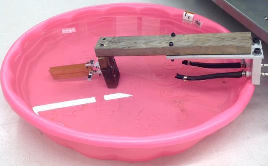


28 FEASIBILITY TESTING
29 FEASIBILITY TESTING Muscles: ½ Diameter, 8 long Fin: 6 long, 45 degrees of angular displacement in each direction Solenoid opening duration: 2 seconds Delay between two muscles: 2 seconds Testing Fluid : Water Pressure : Up to 100 psi (max pressure of pump) Microcontroller : Arduino Uno controlling two solenoids using transistors
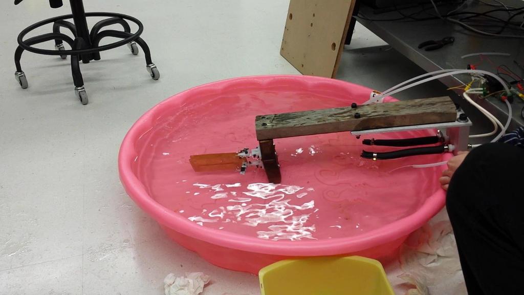
30 FEASIBILITY TESTING
31 BOM AND BUDGET ases Currently have $575 of projected expenditures, including $50 for unforeseen expenses. Options to reduce cost Reducing the number of joints (not recommended) - $70 on solenoids Use roll of gasket material in lab instead of buying new SBR gasket (could compromise sealing) - $9 Reduce battery life from 2.4 hours to.9 hours - $32 (assuming the solenoids have enough power when the battery nears depletion)

32 RISK ASSESSMENT UPDATES
33 PROJECTED MSDII SCHEDULE
34 PROJECTED MSDII SCHEDULE
35 QUESTIONS? CONCERNS? FEEDBACK?
Robofish Charging Station (RCS) Test Plan
 Test Plan") Team P17250 10/26/2016 Rev A Robofish Charging Station (RCS) Test Plan 1 Table of Contents 1. Objectives 2. Test Criteria 3. Test Resources 4. Test Procedures 5. Results 6. Conclusions 1. Objectives 1.1.
Team P17250 10/26/2016 Rev A Robofish Charging Station (RCS) Test Plan 1 Table of Contents 1. Objectives 2. Test Criteria 3. Test Resources 4. Test Procedures 5. Results 6. Conclusions 1. Objectives 1.1.
Project Name: RoboFish Charging Station (RCS)
") Project Name: RoboFish Charging Station (RCS) Project Number: P17250 Project Family: P16029, P16229, P15029, P14029 Start Term: 2161 End Term: 2165 Team Members Jack Moore - Mechanical Engineering - Project
Project Name: RoboFish Charging Station (RCS) Project Number: P17250 Project Family: P16029, P16229, P15029, P14029 Start Term: 2161 End Term: 2165 Team Members Jack Moore - Mechanical Engineering - Project
Auburn University Student Launch. PDR Presentation November 16, 2015
 Auburn University Student Launch PDR Presentation November 16, 2015 Project Aquila Vehicle Dimensions Total Length of 69.125 inches Inner Diameter of 5 inches Outer Diameter of 5.25 inches Estimated mass
Week 11. Module 5: EE100 Course Project Making your first robot
 Week 11 Module 5: EE100 Course Project Making your first robot Dr. Ing. Ahmad Kamal Nasir Office Hours: Room 9-245A Tuesday (1000-1100) Wednesday (1500-1600) Course Project: Wall-Follower Robot Week 1
RIT Formula SAE Senior Design
 RIT Formula SAE Senior Design Agenda Project Description Work Breakdown Customer Needs Customer Specifications Current/Previous System Design Proposed Design #1 Proposed Design #2 Testing Plans Concept
Detailed Design Review
 Detailed Design Review P16241 AUTONOMOUS PEOPLE MOVER PHASE III Team 2 Agenda Problem Definition Review Background Problem Statement Project Scope Customer Requirements Engineering Requirements Detailed
INSTALLATION INSTRUCTIONS
 INSTALLATION INSTRUCTIONS DUAL EXTERNAL PUMP FST Vertical & Horizontal Mount Customer Support: info@radiumauto.com Document: 19-0013 READ AND UNDERSTAND THESE INSTRUCTIONS COMPLETELY BEFORE BEGINNING INSTALLATION
DESIGN & DEVELOPMENT OF SEGWAY
 DESIGN & DEVELOPMENT OF SEGWAY Mr. Velaji Hadiya 1, Mr. Aakash Rai 2, Mr. Sushant Sharma 3, Miss. Ashwini More 4 1Student, Department of Nashik, Maharashtra, India 2Student, Department of Nashik, Maharashtra,
Team 2228 CougarTech 1. Training L2. Electrical Design and Control System Wiring
 Team 2228 CougarTech 1 Training L2 Electrical Design and Control System Wiring Team 2228 CougarTech 2 Objectives Understand: Understand the electrical design process Understand the control system wiring
Click Here for Printable PDF File. CHAPTER 3 - BASIC INFORMATION for PERFORMING HYDRAULIC SYSTEM MAINTENANCE
 HWH Online Technical School Lesson 1: Introduction to Hydraulics Chapter 3 - "BASIC INFORMATION for PERFORMING HYDRAULIC SYSTEM MAINTENANCE" (Filename: ML57000-012-CH3.DOC Revised: 22APR16) Click Here
Over-moldable Ruggedized Connectors for higher Amperage
 Over-moldable Ruggedized Connectors for higher Amperage Understanding Power and the need for interconnect solutions Power: Defined by the rate at which energy is used or generated. Electrical Power can
CRITICAL DESIGN PRESENTATION
 CRITICAL DESIGN PRESENTATION UNIVERSITY OF SOUTH ALABAMA LAUNCH SOCIETY BILL BROWN, BEECHER FAUST, ROCKWELL GARRIDO, CARSON SCHAFF, MICHAEL WIESNETH, MATTHEW WOJCIECHOWSKI ADVISOR: CARLOS MONTALVO MENTOR:
LEVEL 3 BUILD YELLOW BIRD. Dan Schwartz
 LEVEL 3 BUILD YELLOW BIRD Dan Schwartz This entire rocket is built using the same techniques I use for my nose cones, a central airframe tube for compression strength and rings of high compression styrofoam
FAX
 INSTALLATION INSTRUCTIONS 6090 Air Suspension Kit (pat. pending) 1999-2006 Tahoe, Suburban, Avalanche, Yukon Thank you for purchasing a quality Hellwig Product. PLEASE READ THIS INSTRUCTION SHEET COMPLETELY
Course. GNEG 1103 Introduction to Engineering. Assignment. Team Design Project. Project Selected. Solar Powered Stereo Cooler. Project Presentation
 Course GNEG 1103 Introduction to Engineering Assignment Team Design Project Project Selected Solar Powered Stereo Cooler Project Presentation April 23, 2014 Team Members Kenny Callis Ronny Akhaphong Alfredo
BX88175 Installation Instructions ToadStop II Vacuum Brake System
 BX88175 Installation Instructions ToadStop II Vacuum Brake System Serial No. Customer supplied tools & supplies Utility knife, 12VDC tester, drill & bits: (1/8", 1/4", 5/8 ), ¼ socket drive bit, punch,
COMET: Colorado Mini Engine Team Manufacturing Status Review February 3, 2014
 COMET: Colorado Mini Engine Team Status Review February 3, 2014 Team members: Julia Contreras-Garcia Emily Ehrle Eric James Jonathan Lumpkin Matthew McClain Megan O Sullivan Benjamin Woeste Kevin Wong
Illinois Space Society Flight Readiness Review. University of Illinois Urbana-Champaign NASA Student Launch March 30, 2016
 Illinois Space Society Flight Readiness Review University of Illinois Urbana-Champaign NASA Student Launch 2015-2016 March 30, 2016 Team Managers Project Manager: Ian Charter Structures and Recovery Manager:
WHIRLWIND. Owner s Manual 151H Series (Rev ) Model: 151H Serial Number: Manufacture Date: A V I A T I O N WHIRL WIND AVIATION
 Model: 151H Serial Number: Manufacture Date: A V I A T I O N WHIRL WIND AVIATION") WHIRLWIND A V I A T I O N M a nufacturer of Composite Constant Speed P r o pellers Model: 151H Serial Number: Manufacture Date: Owner s Manual 151H Series (Rev 2014-2) WHIRL WIND AVIATION 1419 STATE ROUTE
WHIRLWIND A V I A T I O N M a nufacturer of Composite Constant Speed P r o pellers Model: 151H Serial Number: Manufacture Date: Owner s Manual 151H Series (Rev 2014-2) WHIRL WIND AVIATION 1419 STATE ROUTE
Hydraulic Oil Cooler. Assembly Instructions (Originating w/serial Number )
") Hydraulic Oil Cooler Case 465 Skid Steer Assembly Instructions (Originating w/serial Number 50-101) Model Number: Serial Number: Date of Purchase: Specialized Equipment, Inc. 650 So. Main Street - PO Box
Hydraulic Oil Cooler Case 465 Skid Steer Assembly Instructions (Originating w/serial Number 50-101) Model Number: Serial Number: Date of Purchase: Specialized Equipment, Inc. 650 So. Main Street - PO Box
The H-MAC Heavy Metal Articulating Chassis Construction Guide
 The H-MAC Heavy Metal Articulating Chassis Construction Guide The Heavy Metal Chassis is constructed with two identical drive modules built using 10 mechanical sub-assemblies. The drive modules are integrated
MARINE PROPULSION CONTROL
 PRODUCT BULLETIN SB-8504B MARINE PROPULSION CONTROL ELECTRONIC LOGIC AND CONTROL PANEL Type MPC-E9 Control Panel APPLICATION Propulsion controls for small and large vessels with fixed pitch propellers,
TiAL R770 & S605. Installation notes. TIAL Sport!! TiALsport.com!! Revision 2
 TiAL R770 & S605 Installation notes TIAL Sport!! TiALsport.com!! Revision 2 Caution! The components in this package may require additional parts to be sourced or fabricated for the installation. Due to
2013 Vandal Pumpkin Cannon Owner s Manual
 2013 Vandal Pumpkin Cannon Owner s Manual Warning: This cannon uses compressed air to launch pumpkins at dangerous speeds. A direct hit at any range can cause serious internal injury and death. It must
TECHNICAL PAPER 1002 FT. WORTH, TEXAS REPORT X ORDER
 I. REFERENCE: 1 30 [1] Snow Engineering Co. Drawing 80504 Sheet 21, Hydraulic Schematic [2] Snow Engineering Co. Drawing 60445, Sheet 21 Control Logic Flow Chart [3] Snow Engineering Co. Drawing 80577,
C-Drive 7 Motor Control Unit For Electric Steering & Autopilots
 C-Drive 7 Motor Control Unit For Electric Steering & Autopilots OPERATION AND INSTALLATION MANUAL www.tmq.com.au TMQ C-Drive7 Page 2 of 20 28/04/2009 Index INTRODUCTION 4 BLOCK DIAGRAM OF FULL SYSTEM 5
Auburn University. Project Wall-Eagle FRR
 Auburn University Project Wall-Eagle FRR Rocket Design Rocket Model Mass Estimates Booster Section Mass(lb.) Estimated Upper Section Mass(lb.) Actual Component Mass(lb.) Estimated Mass(lb.) Actual Component
ENGINE COOLING SYSTEM GENERAL 1. GENERAL SPECIFICATIONS ENGINE COOLING SYSTEM. undefined
 211001 043 GENERAL 1. GENERAL SPECIFICATIONS 211001 044 211001 2. FASTENER TIGHTENING SPECIFICATIONS 211001 045 OVERVIEW AND OPERATION PROCESS 1. COMPONENT LOCATOR 1. Reserver Tank 2. Deaeration Tube 3.
e-nable Hand Test Rig
 enable Hand Test Rig P606 David Schwartz, Tia Parks, Shannon Barry, Samantha Mason, Charles Rumfola Agenda Recap Customer Requirements Engineering Requirements Effective Access Technology Conference Subsystems
4-Bulkheads. Bulkheads. December XLR Page 4-1
 Bulkheads December 2007 04-XLR Page 4-1 This Page Intentionally Left Blank Page 4-2 04-XLR December 2007 Contents 4.0 - Chapter Preface...4-4 4.0.1 - Parts List... 4-4 4.0.2 - Tools List... 4-4 4.0.3 -
WHIRLWIND. Owner s Manual Series (Rev ) Serial Number: Manufacture Date: A V I A T I O N Model: WHIRL WIND AVIATION
 Serial Number: Manufacture Date: A V I A T I O N Model: WHIRL WIND AVIATION") WHIRLWIND A V I A T I O N Model: 100-4 Serial Number: 100-4- Manufacture Date: M a nufacturer of Composite Constant Speed P r o pellers Owner s Manual 100-4 Series (Rev 2014-2) WHIRL WIND AVIATION 1419
WHIRLWIND A V I A T I O N Model: 100-4 Serial Number: 100-4- Manufacture Date: M a nufacturer of Composite Constant Speed P r o pellers Owner s Manual 100-4 Series (Rev 2014-2) WHIRL WIND AVIATION 1419
Manifold QF. Contents. Description. Installation & Setup Guide. Safety 3. Introduction 3. Installation Standards 4. Specifications 5.
 Contents Description Page Safety 3 Introduction 3 Installation Standards 4 Specifications 5 Materials 5 Overall System Configurations 6 Manifold Installation 7 Fixing Unit to Wall 7 Water Connection 8
To ensure proper installation, digital pictures with contact information to before startup.
 Check List for Optimal Filter Performance [ ] There should be no back-pressure on the flush line. A 1 valve should have a 2 waste line, and 2 valve should have a 3 waste line. Do not use rubber hosing
Critical Design Review
 Critical Design Review University of Illinois at Urbana-Champaign NASA Student Launch 2017-2018 Illinois Space Society 1 Overview Illinois Space Society 2 Launch Vehicle Summary Javier Brown Illinois Space
Preliminary Design Review. California State University, Long Beach USLI November 13th, 2017
 Preliminary Design Review California State University, Long Beach USLI November 13th, 2017 System Overview Launch Vehicle Dimensions Total Length 108in Airframe OD 6.17in. ID 6.00in. Couplers OD 5.998in.
SD Bendix MV-1 Modutrol DESCRIPTION
 SD-03-3411 Bendix MV-1 Modutrol VALVE A 5-3/8 VALVE B VALVE C VALVE E VALVE D FIGURE 1 - MV-1 MODUTROL DESCRIPTION The Bendix MV-1 modutrol assembly is an integrated air control module designed for dash
NASA University Student Launch Initiative (Sensor Payload) Final Design Review. Payload Name: G.A.M.B.L.S.
 Final Design Review. Payload Name: G.A.M.B.L.S.") NASA University Student Launch Initiative (Sensor Payload) Final Design Review Payload Name: G.A.M.B.L.S. CPE496-01 Computer Engineering Design II Electrical and Computer Engineering The University of
NASA University Student Launch Initiative (Sensor Payload) Final Design Review Payload Name: G.A.M.B.L.S. CPE496-01 Computer Engineering Design II Electrical and Computer Engineering The University of
StratoLauncher IV Ultimate Assembly Instructions [launch video:
 StratoLauncher IV Ultimate Assembly Instructions [launch video: https://youtu.be/uebmkyz07zq] Tools required for assembly and items needed to launch rocket: An adjustable wrench, 14mm wrench, 4mm & 5mm
QUANTUM SERIES JUICE DISPENSER
 QUANTUM SERIES JUICE DISPENSER l IPL Manual Release Date: April 25, 2001 Publication Number: 720901120IPL Revision Date: April 28, 2014 Revision: C Visit the Cornelius web site at www.cornelius.com for
Electrical Components Bill of Materials (BOM)
") 2.12 Electrical System Installation Electrical Components Bill of Materials (BOM) Item Qty. Description 1 1 ea. Activation Microswitch 2 1 ea. Activation Microswitch bracket 3 2 ea. Activation Microswitch
2.12 Electrical System Installation Electrical Components Bill of Materials (BOM) Item Qty. Description 1 1 ea. Activation Microswitch 2 1 ea. Activation Microswitch bracket 3 2 ea. Activation Microswitch
Slip Ring Connection Board Version 1.0 User s Manual
 Slip Ring Connection Board Version 1.0 User s Manual Document Revision: 1.0 8/21/2010 Copyright by Scott Gray, 2010. Replication or reproduction in whole or in part is strictly prohibited without express
Assembly Procedures. For P13051, PIV in a Lung Model
 For Senior Design Project P13051, PIV in a Lung Model. These documents describe how to assemble each component of the system. Assembly Procedures For P13051, PIV in a Lung Model Table of Contents Lung
INSTALLATION INSTRUCTIONS FUEL SURGE TANK KIT
 INSTALLATION INSTRUCTIONS FUEL SURGE TANK KIT BMW E46 3-Series, Excl Convertible Document: 19-0056 Support: info@radiumauto.com Relieve fuel pressure in vehicle before beginingthe installation. Disconnect
StratoLauncher IV Assembly Instructions
 Tools required for assembly and items needed to launch rocket: An adjustable wrench (or a 14mm wrench), 4mm & 5mm hex wrench, and Phillips head screwdriver. A plastic (PET*) soda bottle, nose cone, water,
Christine Tartaglia Individual Report: Week 1 February 1, 2012
 Over winter break, Nicole and I got together three separate times. The first time, we went to Home Depot and PETCO to look at tubing to build air muscles. At PETCO, we purchased tubing that we thought
CRITICAL DESIGN REVIEW. University of South Florida Society of Aeronautics and Rocketry
 CRITICAL DESIGN REVIEW University of South Florida Society of Aeronautics and Rocketry 2017-2018 AGENDA 1. Launch Vehicle 2. Recovery 3. Testing 4. Subscale Vehicle 5. Payload 6. Educational Outreach 7.
Test Plans & Test Results
 P10227 Variable Intake System for FSAE Race Car Test Plans & Test Results By: Dave Donohue, Dan Swank, Matt Smith, Kursten O'Neill, Tom Giuffre Table of contents 1. MSD I: WKS 8-10 PRELIMINARY TEST PLAN...
Integrated Engineering MK7/MQB Cold Air Intake Install Guide IEINCI2 & IEINCI8
 Integrated Engineering MK7/MQB Cold Air Intake Install Guide IEINCI2 & IEINCI8 Thank you for purchasing another high quality Integrated Engineering product! This instruction guide is used for installation
Detailed Design Review
 Detailed Design Review Reciprocating Friction Tester : Armature Subsystem Thursday December 4th, 2014 1 : Armature Subsystem Eric Kutil (ME): Project Manager Specialty: Solid Modeling and Machining Chris
Presentation Outline. # Title # Title
 CDR Presentation 1 Presentation Outline # Title # Title 3 4 5 6 7 8 9 10 11 12 13 14 15 16 17 18 19 20 21 22 23 24 25 26 Team Introduction Vehicle Overview Vehicle Dimensions Upper Body Section Payload
4100C BOSS AC Shovel Drive System Overview. WMEA Edmonton - June 2008
 4100C BOSS AC Shovel Drive System Overview WMEA Edmonton - June 2008 Overview Drives Partnership with ABB Deck Plan / One-Line Schematic ISU (IGBT Supply Unit) Shovel Motion Inverters Cabling / Grounding
AFT MOUNTED OXYGEN SYSTEM INSTALLATION BEECHCRAFT 33, 35, 36, 55, AND 58
 ENGINE TECHNOLOGIES INC. REPORT 35-4960004, REV. A, JULY 12, 2013 INSTALLATION INSTRUCTIONS FOR OXYGEN SYSTEM ON HAWKER BEECHCRAFT S35, V35, V35A, V35B, 35-C33A, E33A, 36, A36, F33A, G33, 95-55, 95-A55,
Solar Powered Water Filtration System
 Backwoods Power & Water Solar Powered Water Filtration System Steven Guy & Ryan Graves, UA ECE Department April 21, 2012 1 Background Senior Design Course (2 semester sequence) Concept Fabrication Testing
OPERATION MANUAL MODELS TWE-250 TWE-321 TWE-375 TRU WELD EQUIPMENT COMPANY 6400 N. HONEYTOWN ROAD SMITHVILLE, OHIO (330)
") OPERATION MANUAL MODELS TWE-250 TWE-321 TWE-375 TRU WELD EQUIPMENT COMPANY 6400 N. HONEYTOWN ROAD SMITHVILLE, OHIO 44677 (330) 669 2773 CONTENTS Section Description Pages 1 Introduction 3 2 External Features
OPERATION MANUAL MODELS TWE-250 TWE-321 TWE-375 TRU WELD EQUIPMENT COMPANY 6400 N. HONEYTOWN ROAD SMITHVILLE, OHIO 44677 (330) 669 2773 CONTENTS Section Description Pages 1 Introduction 3 2 External Features
INSTRUCTIONS. #82044 Race Diesel Nitrous System
 INSTRUCTIONS #82044 Race Diesel Nitrous System Thank you for choosing ZEX products; we are proud to be your manufacturer of choice. Kit Parts List Description Qty. Description Qty. Nitrous Solenoid 2.088
Click Here for Printable PDF File
 HWH Online Technical School Lesson 13: Hydraulic Leveling System Identification and Operation PART 2 Computer-Control (Automatic) Leveling Systems The 400 Series 610 Central Ground Series (400 / 500 /
Project Narrative Description
 0 Project Narrative Description Charge Spot is intended to demonstrate the feasibility of an autonomous electric vehicle charging system for residential use. The goal of Charge Spot is to have no user
1. CONDITIONS FOR USE 2. SAFETY
 1. CONDITIONS FOR USE This micro abrasive blaster may only be operated: Indoors; Below 6500 ft above sea level altitude; Ambient air temperature between 40-105 F (5-40 C); Maximum relative humidity of
ASME Human Powered Vehicle
 ASME Human Powered Vehicle By Yousef Alanzi, Evan Bunce, Cody Chenoweth, Haley Flenner, Brent Ives, and Connor Newcomer Team 14 Mid-Point Review Document Submitted towards partial fulfillment of the requirements
Weistec M157 WMI System
 Weistec M157 WMI System Installation Guide 2012-2013 E63 2014+ E63 4matic(S) 2011-2013 CLS63 2014+ CLS63 4matic(S) 2015+ S63 AMG (Without ABC Suspension) This product is legal in California for racing
Single Nozzle Systems UNIVERSAL NOZZLE SYSTEM INSTRUCTIONS Part #'S 00-1XXXXX
 INTRODUCTION Thank you for purchasing the highest quality nitrous system on the market. Nitrous Outlet strives to offer the best product with the best price and customer service available. Nitrous Outlet
Georgia Tech NASA Critical Design Review Teleconference Presented By: Georgia Tech Team ARES
 Georgia Tech NASA Critical Design Review Teleconference Presented By: Georgia Tech Team ARES 1 Agenda 1. Team Overview (1 Min) 2. 3. 4. 5. 6. 7. Changes Since Proposal (1 Min) Educational Outreach (1 Min)
HWH Online Technical School Lesson 10: Air Suspension and HWH (Filename: ML DOC Revised: 23APR16) Click Here for Printable PDF File
 Click Here for Printable PDF File") CHAPTER 1 - Preface HWH Online Technical School Lesson 10: Air Suspension and HWH (Filename: ML57000-018.DOC Revised: 23APR16) Click Here for Printable PDF File CHAPTER 2 - Hydraulic Leveling and Air Suspensions
CHAPTER 1 - Preface HWH Online Technical School Lesson 10: Air Suspension and HWH (Filename: ML57000-018.DOC Revised: 23APR16) Click Here for Printable PDF File CHAPTER 2 - Hydraulic Leveling and Air Suspensions
EGG 101L INTRODUCTION TO ENGINEERING EXPERIENCE
 EGG 101L INTRODUCTION TO ENGINEERING EXPERIENCE LABORATORY 11: AUTOMATED CAR PROJECT DEPARTMENT OF ELECTRICAL AND COMPUTER ENGINEERING UNIVERSITY OF NEVADA, LAS VEGAS GOAL: This section combines the motor
FRS26H5DSB3 FRS26H5DSB4
 Product No. SB3 SB4 Series R134a R134a Color stain/blk stain/blk Volts 115 115 Wiring Diagram 241526901 241526901 Owner's Guide 241572801 241572801 Market North America North America Energy Guide 241538755
FAX
 INSTALLATION INSTRUCTIONS 6299 Air Suspension Kit (pat. pending) 2009+ Dodge 1500 Pickup with Rear Coil Springs Thank you for purchasing a quality Hellwig Product. PLEASE READ THIS INSTRUCTION SHEET COMPLETELY
INSTALLATION INSTRUCTIONS Auto Level Compressor Kit IMPORTANT NOTES
 INSTALLATION INSTRUCTIONS 4880 Auto Level Compressor Kit Thank you for purchasing a quality Hellwig Product. PLEASE READ THIS INSTRUCTION SHEET COMPLETELY BEFORE STARTING YOUR INSTALLATION IMPORTANT NOTES
INSTALLATION INSTRUCTIONS AOS-R (Air Oil Separator-Return) Turbo Subaru and STi
 Turbo Subaru and STi") INSTALLATION INSTRUCTIONS AOS-R (Air Oil Separator-Return) 02-14 Turbo Subaru and 2015+ STi These instructions are based on a vehicle with an OEM turbocharger and top-mount intercooler. If a front-mount
INSTALLATION INSTRUCTIONS AOS-R (Air Oil Separator-Return) 02-14 Turbo Subaru and 2015+ STi These instructions are based on a vehicle with an OEM turbocharger and top-mount intercooler. If a front-mount
Presentation Outline. # Title
 FRR Presentation 1 Presentation Outline # Title 3 4 5 6 7 8 9 10 11 12 13 14 15 16 17 18 19 20 21 22 23 24 Team Introduction Mission Summary Vehicle Overview Vehicle Dimensions Upper Body Section Elliptical
DMC mA Positioner
 DMC-100 4-20mA Positioner TELEPHONE: +1-859-727-7890 TOLL FREE: +1-800-662-9424 FAX: +1-859-727-4070 E-MAIL: DVOGES@INDELAC.COM MROBINSON@INDELAC.COM TCAYWOOD@INDELAC.COM SHIPPING ADDRESS: 6810 POWERLINE
Originators of insulated poly waterers
 Originators of insulated poly waterers Quality Waterers Personalized Service TABLE OF CONTENTS PRODUCT DETAILS...2-3 BALL CLOSURE/SWINE WATERERS E-Fount / General Livestock...4 E-Fount / Swine...5 MiraFount
INTERNATIONAL 3200 AND Freightliner MB
 An ISO 9001:2000 Registered Company INTERNATIONAL 3200 AND Freightliner MB55 2002-2008 Intelligent Lift Interlock System (ILIS701-D) - Installation Instructions International & MB45/55 w/allison 2000 and
Holley Ford 351W Hi-Ram Modular Intake Manifold Kits
 Holley Ford 351W Hi-Ram Modular Intake Manifold Kits Holley P/N Engine Application & Induction Configuration 300-241 Hi-Ram, 1 x 95mm LS Throttle Body (longitudinal mount) w/ port EFI provisions & fuel
RIT Arm V2 Supinating/Pronating Wrist
 RIT Arm V2 Supinating/Pronating Wrist Derek Gagnon RIT BioPrint & Limb Forge Rochester Institute of Technology Rochester, New York 14623 June 26, 2018 Table of Contents: I. Purpose/Overview II. Design
Surface and Brakes Anti-Ice Systems
 Surface and Brakes Anti-Ice Systems WING DEICE DISTRIBUTOR VALVE TAIL DEICE R BLEED FAIL VDC FROM RIGHT ENGINE P3 PNEUMATIC AIR SHUTOFF VALVE N.O. R BK DEICE ON Ice and Rain Protection N.C. TO DOOR SEAL
Cornell University Autonomous Underwater Vehicle Team Spring Frame
 Cornell University Autonomous Underwater Vehicle Team Spring 2014 Frame Technical Report Kent Esslinger (kde26) May 21, 2014 Contents 1 Abstract 2 2 Design Requirements 2 3 Previous Designs 3 3.1 Drekar...............................
UC Berkeley Space Technologies and Rocketry Preliminary Design Review Presentation. Access Control: CalSTAR Public Access
 UC Berkeley Space Technologies and Rocketry Preliminary Design Review Presentation Access Control: CalSTAR Public Access Agenda Airframe Propulsion Payload Recovery Safety Outreach Project Plan Airframe
FUSELAGE ASSEMBLY SECOND SECTION (of three)
") FUSELAGE ASSEMBLY SECOND SECTION (of three) 1 FRONT FLOOR ASSEMBLY The front floor assembly is fabricated from three pieces of the two ply pre-pregnated panel material supplied. The basic floor panel and
FUSELAGE ASSEMBLY SECOND SECTION (of three) 1 FRONT FLOOR ASSEMBLY The front floor assembly is fabricated from three pieces of the two ply pre-pregnated panel material supplied. The basic floor panel and
INSTALLATION, OPERATION AND MAINTENANCE MANUAL
 TYPE (BSA) SEALED VALVE BODY Series 2002 INSTALLATION, OPERATION AND MAINTENANCE MANUAL 1998-2013 by RF Valves, Inc. CUSTOMER SERVICE HOT-LINE 1-410-850-4404 Page 2 of 9 CONTENT 1.0 Introducing the airflex
University of Wisconsin-Platteville Formula SAE Design Report
 2012-2013 University of Wisconsin-Platteville Formula SAE Design Report Introduction The 2012-2013 University of Wisconsin-Platteville Formula SAE Team is competing in Formula SAE, Nebraska, for the second
Models: 8500, 8501, 8513, 8514, 8500BL, 8501BL, 8513BL, 8514BL, 8540, 8541, 8550, 8551, 8540BL, 8541BL, 8550BL & 8551BL
 Standard Pump Ultra Mass High Viscosity Batch Control System Description Standard s Drum Pumps are designed to transfer a variety of materials from 55 gallon drums and tanks. Standard Pump offers several
SECTION Automatic Transaxle/Transmission 6R80
 307-01-i Automatic Transaxle/Transmission 6R80 307-01-i SECTION 307-01 Automatic Transaxle/Transmission 6R80 CONTENTS PAGE IN-VEHICLE REPAIR Main Control... 307-01-2 307-01-2 Automatic Transaxle/Transmission
Switch Pro w/ Compact Junction Box A_1_ Series Owner s Manual
 Warranty, Service & Repair To register your product with the manufacturer, go to the Flowline website for on-line registration. The website address is as follows: www.flowline.com On-line Warranty Registration
Veescan H Eddy Current Wheel Inspection System
 H Eddy Current Wheel Inspection System Maximum flexibility Full choice of Operation Modes maximising Probability of Detection Easy & fast reporting Easy to operate with basic training Introducing The Veescan
WHIRLWIND. Owner s Manual 375RV Series (Rev ) Model: 375RV Serial Number: 375RV- Manufacture Date: A V I A T I O N WHIRL WIND AVIATION
 Model: 375RV Serial Number: 375RV- Manufacture Date: A V I A T I O N WHIRL WIND AVIATION") WHIRLWIND A V I A T I O N M a nufacturer of Composite Constant Speed P r o pellers Model: 375RV Serial Number: 375RV- Manufacture Date: Owner s Manual 375RV Series (Rev 2014-3) WHIRL WIND AVIATION 1419
WHIRLWIND A V I A T I O N M a nufacturer of Composite Constant Speed P r o pellers Model: 375RV Serial Number: 375RV- Manufacture Date: Owner s Manual 375RV Series (Rev 2014-3) WHIRL WIND AVIATION 1419
Physical The ROV will be inspected for any items that may be unsafe to the participants or the facility.
 Documentation Be sure and bring these items to the safety inspection table; they will be used to help answer questions. Physical The ROV will be inspected for any items that may be unsafe to the participants
ARC4000e 4 wheel compressor system w / 4 way Ride Pro controller
 350 S. St. Charles St. Jasper, In. 47546 Ph. 812.482.2932 Fax 812.634.6632 on the internet: www.ridetech.com ARC4000e 4 wheel compressor system w / 4 way Ride Pro controller 1 ARC5001 Compressor 1 CON6000
Table of Contents OVERVIEW VALUES DECLARATION TEAM ORGANIZATIONAL CHART
 OVERVIEW VALUES DECLARATION TEAM ORGANIZATIONAL CHART Table of Contents INTRODUCTION SPECIFICATIONS FEATURES BASIC COMPONENTS OF CAR (READYMADE) BASIC COMPONENTS OF CAR (FABRICATED) MECHANICAL COMPONENTS
STARTING SYSTEMS 8B - 1 STARTING SYSTEMS CONTENTS
 TJ STARTING SYSTEMS 8B - 1 STARTING SYSTEMS CONTENTS page DESCRIPTION AND OPERATION STARTER MOTOR... 2 STARTER RELAY... 3 STARTING SYSTEM... 1 DIAGNOSIS AND TESTING STARTER MOTOR... 8 STARTER MOTOR NOISE
Carb2EFI Fuel System Conversion Kit Intank Fuel Pump (450 LPH Gasoline/E85 Compatible)
") Carb2EFI Fuel System Conversion Kit Intank Fuel Pump (450 LPH Gasoline/E85 Compatible) Thanks for your purchase of this kit. We have worked hard to provide kits that contain exactly what you need No more
Carb2EFI Fuel System Conversion Kit Intank Fuel Pump (450 LPH Gasoline/E85 Compatible) Thanks for your purchase of this kit. We have worked hard to provide kits that contain exactly what you need No more
Irate Diesel Regulated Return install:
 Irate Diesel Regulated Return install: 1. Remove IC piping and intake Y. It may also be easier to remove the Downpipe and turbo to gain access to the back fittings. This will depend upon how much you want
Engineering Operation & Maintenance. Leak Detector. Advance your process TO REPLACE WIL E-01 WIL E-01
 WG Leak Detector Engineering Operation & Maintenance Advance your process WIL-19050-E-02 TO REPLAE WIL-19050-E-01 WIL-19050-E-01 K I P P SENSOR ABLE SPEIFIATIONS The sensor cables utilize high Beryllium
PRELIMINARY DESIGN REVIEW
 PRELIMINARY DESIGN REVIEW AUBURN UNIVERSITY NASA LUNABOT TEAM MARCH 28, 2014 MATTHEW JONES DAVID FAUCETT STEWARD BOYD WILL FLOURNOY TECHNICAL ADVISOR/OVERLORD - DR. BEALE SPONSORS-DR. MADSEN, DR. WILLIAMS,
Simple Line Follower robot
 Simple Line Follower robot May 14, 12 It is a machine that follows a line, either a black line on white surface or vise-versa. For Beginners it is usually their first robot to play with. In this tutorial,
Model No. SP Low Volume Low Pressure (LVLP) Gravity Feed Spray Gun
 Gravity Feed Spray Gun") Model No. SP-33000 Low Volume Low Pressure (LVLP) Gravity Feed Spray Gun - 1 - TABLE OF CONTENTS: 1. Description 2. Specification and Technical Data 3. Important Safety Instruction 4. Instructions for
Model No. SP-33000 Low Volume Low Pressure (LVLP) Gravity Feed Spray Gun - 1 - TABLE OF CONTENTS: 1. Description 2. Specification and Technical Data 3. Important Safety Instruction 4. Instructions for
Data sheet chainflex CF8821
 1. Outer jacket: Pressure extruded, oil-resistant PVC mixture 2. Overall shield: Braiding made of tinned copper wires 3. Overall banding: Plastic foil 4. Core insulation: Mechanically high-quality TPE
TS1251 PRESSURE DISPENSER USER'S MANUAL
 TS1251 PRESSURE DISPENSER USER'S MANUAL TABLE OF CONTENTS SECTION DESCRIPTION PAGE NUMBER 1.0 CAUTIONS AND WARNINGS... 3 2.0 INTRODUCTION... 4 3.0 DESCRIPTION... 4 & 5 4.0 SET UP AND INSTALLATION... 6
Bolt on handle and mounting kit included in price. Bolt on handle and mounting kit included in price.
 Extruded Plain Extruded aluminum provides strength, yet weighs less than other models with the same solid construction and protection. Extruded plain model is a great economical cab protector, while still
Installation Guide. Thermal Conductivity Detector on a 6850 GC Accessory G2623A
 Installation Guide Thermal Conductivity Detector on a 6850 GC Accessory G2623A 2 Agilent Technologies 2007 All Rights Reserved. Reproduction, adaptation, or translation without permission is prohibited,