Wheels Brakes Tires Hydraulic hoses/ fittings Landing Gear SPARE PART CATALOGUE. Price list EURO
|
|
|
- Ralph Montgomery
- 6 years ago
- Views:
Transcription


1 Wheels Brakes Tires Hydraulic hoses/ fittings Landing Gear SPARE PART CATALOGUE Price list EURO
2 GENERAL MAINTENANCE AND INSTALLATION MANUAL The instructions detailes following are general instruction concerning BERINGER wheels and brakes. They can be used for the installation of BERINGER products on Light and Experimental planes. If you have purchased products for a certified Aircraft you must refer to the Maintenance and Overhaul Manual in reference with your products. The word equipment as used in this document is the entire unit : complete wheel or wheel with brake and disc. wheel or wheel assembly includes flanges, central spacer, bearings, circlips, assembly bolts, drive keys, valve and seals brake or caliper or brake assembly includes housing, pistons, seals, back plate, bolts, pads and disc. The disc is not bolted on the wheel so it is not considered to be part of the wheel assembly. The disc is also not fixed to the brake but for convenience it is considered as part of the brake assembly. pad includes the brake lining and the steel plate supporting the brake lining. Lining is the wearable material. Please note that pad is always used in this document because in BERINGER systems the lining is part of the pad and cannot be taken apart from the steel plate. Cleaning The aluminium parts are protected from corrosion with an anodizing coating. This thin coating does not protect against basic agent with ph > 9. CAUTION: coating Cleaning the wheel and brake parts with basic agent may remove totally the anodizing Acid agent may also attack the anodizing. For cleaning the wheel and brake parts we recommend using only water and soap or dry clothes. CONDITIONNING PROCEDURE When new brake pads have been installed, it is important to condition them properly to obtain the service life designed into them. Rated brake torque value is reached only after a full conditioning of brake pads and disc. CAUTION: Brake torque value can be only 50% of rated brake torque before the conditioning. It means that even with full brake effort the aircraft will not stop as usual. Pilot must take into consideration this parameter to avoid loose of aircraft control during the conditioning procedure. CONDITIONNING PROCEDURE: 1. Taxi aircraft for 500m (1500 feet) with light brake effort. 2. Perform two (2) consecutive stops from knots down to 5 knots. Apply light brake effort during these two stops; do not try to apply full brake effort. Page 129
3 3. Allow the brakes to cool down for 10 to 15 minutes. 4. Apply brakes and check for restraint at high static throttle. If brakes hold, conditioning is complete. 5. If brakes cannot hold aircraft during static run-up, allow the brakes to cool completely and repeat steps 1 through 4. This conditioning procedure will wear off high spots and prepare pads and disc friction surfaces. A visual inspection of disc will indicate the pads condition: a smooth surface with light and regular grooves indicates that pads and disc are properly conditioned. NOTE: A rough surface of disc with deep grooves and isolated bumps indicates that an excessive brake effort has been applied during conditioning. In this case, bumps must be sanded and conditioning procedure repeated. CAUTION: A wrong conditioning may affect brake performances and increase wear of pads and disc. WHEELS Disassembly Reassembly Tire change DISASSEMBLY: WARNING: Do not attempt to disassemble wheel until tire has been completely deflated. Otherwise, serious injury to personnel or damage to equipment can result. WARNING: Do not attempt to remove valve core until tire has been completely deflated. Valve core will be ejected at high velocities if unscrewed before air pressure has been released. a) remove wheel from aircraft b) remove valve cap and apply a tire deflator to release tire pressure completely. Then remove the valve core. c) break the beads away from the wheel flanges by applying pressure by hand or using a wood or plastic tool as close to the tire bead as possible. Tire lubricant may be used to help. Repeat the operation every 90 on both sides, see pictures next: Page 130
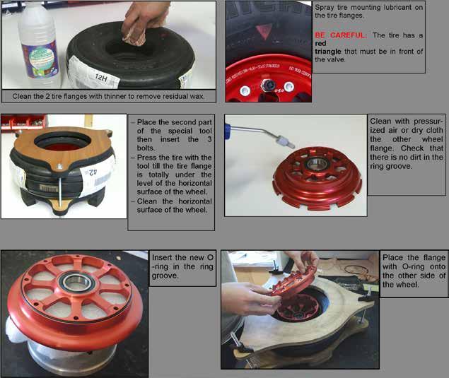
4 CAUTION: Do not pry between tire bead and wheel flange, this may destroy the structural and sealing properties of the wheel and tire. d) Remove all screws holding wheel halves together. CAUTION: Do not use impact or power wrenches Do not remove assembly screws before the tire beads are fully free from the wheel e) Separate wheel halves, remove the tire and o-ring f) Carefully lay the wheel halves on a flat clean bench. CLEANING: a) Clean all metal parts using water and soap, then wipe dry with a clean cloth. Valve core and central spacer must not be cleaned with solvent. CAUTION: Do not use basic or acid agent on wheel halves. Anodizing can be totally removed within few minutes in contact with basic agent. Make sure that cleaning soap is not basic. CAUTION: Sealing of ball bearings must not be damaged or cleaned with solvent. b) Clean wheel bead seat with dry-cleaning solvent and wipe dry with a clean cloth. CAUTION: oily solvent must not be used on wheel bead seat because tire will not stick properly on the wheel. WARNING: Dry-cleaning solvents are toxic and volatile. Use a well-ventilated room. Avoid contact with skin or clothing. Do not inhale the vapor. c) Apply air pressure to dry internal threads CAUTION: oily solvent or oily air pressure must not be used on internal thread because threadlocker will not properly lock the screws. REASSEMBLY: Tools and lubricants required: - Plywood tool with conical bushing P/N: OPA01 - Threadlocker medium strength Loctite Tire lubricant - Dry-cleaning solvent - Torque wrench a) Check ball bearings and seals, replace them if required b) Make sure that the inside of tire is clean and dry. Clean tire bead seat with a cloth impregnated with dry-cleaning solvent as to remove residual grease or wax CAUTION: oily solvent must not be used on tire bead seat because tire will not stick properly on the wheel. Page 131


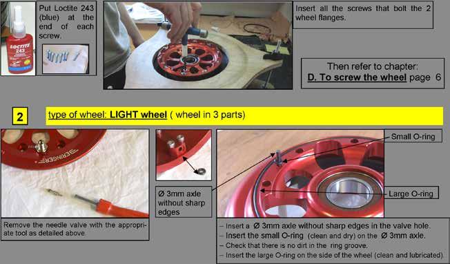
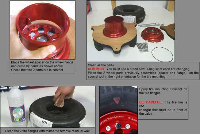
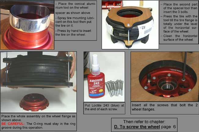
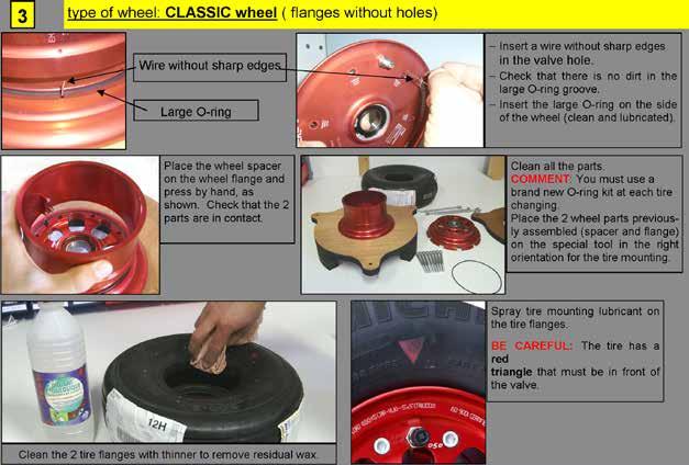
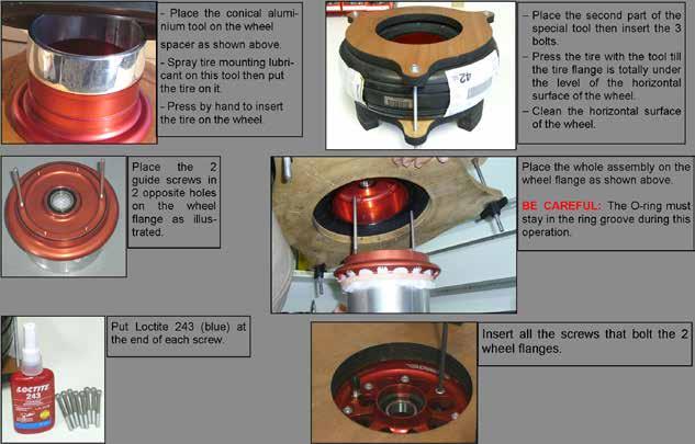
5 Procedure to change tire on the BERINGER wheel SL & LE 6 inch - LIGHT 5 and 6 inch - CLASSIC 6 inch Page 132
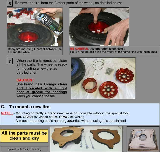
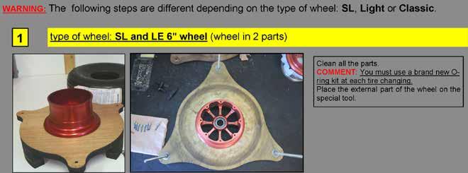
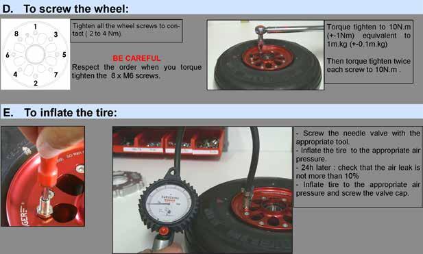
6 Page 133
7 Page 134
8 Page 135
9 Page 136
10 Page 137
11 Maintenance of wheel assembly The maintenance consists in the inspection of the wheel parts and if required the replacement of next parts: - sealed ball bearings - circlips - assembly screws - clips (RF-018(-) only) NOTE: Maintenance can be performed by service center or at BERINGER factory. a) Disassemble the wheel respecting the previous procedure b) Remove circlips on wheel half with lock ring pliers c) Place wheel flange in an oven at 110 C (230 F) to 120 C (250 F) for 30 minutes, never exceed 150 C (300 F) d) Remove wheel half from heat source and immediately remove bearing. If the bearing does not fall out by himself: tap it evenly with a fiber drift pin or use a suitable arbor press. CAUTION: Do not reuse a ball bearing that has already been mounted, even if in new condition. e) Remove screws and clips if they are out of tolerance. CAUTION: Clip screws have been mounted with threadlocker: do not force while screwing out the small screws otherwise you may break the screw. CLEANING: Clean all metal parts using water with soap or cleaning solvent and wipe dry with a clean cloth. CAUTION: Do not use basic or acid agent on wheel halves. Anodizing can be totally removed within few minutes in contact with basic agent. Make sure that cleaning soap is not basic. Apply air pressure to dry internal threads CAUTION: oily solvent or oily air pressure must not be used on internal thread because threadlocker will not properly lock the screws. Page 138
12 INSPECTION: Visually inspect wheel flanges for cracks, nicks, corrosion, or other damage. Causes for replacement of wheel flanges: 1. Signs of deep corrosion in critical areas 2. Anodizing color removed on more than 15% of external surface 3. Heavy nicks 4. Deformed flanges 5. Damaged bearing bore CAUTION: Anodizing coating must not be painted. Do not use sandpaper on any parts. Sandpaper will remove anodizing coating. Visually inspect outer wheel half for scratches, nicks, corrosion, or other damage. Causes for replacement of outer wheel half : 1. Signs of deep corrosion in critical areas 2. Anodizing color removed on more than 15% of external surface 3. Heavy nicks 4. Scratches on sealing surfaces in contact with o-ring REASSEMBLY: a) Place wheel flange in an oven at 110 C (230 F) to 120 C (250 F) for 30 minutes, never exceed 150 C (300 F) CAUTION: bore. Do not attempt to install bearing without heating the wheel flange, it will damage bearing b) Use a new sealed ball bearing CAUTION: Do not reuse a ball bearing that has already been mounted, even if in new condition. CAUTION: Use only a ball bearing approved by BERINGER. There are many different qualities in ball bearings and most of them are not compliant with BERINGER requirements. c) Install the ball bearing into bearing bore of heated wheel flange using appropriate tool. Tap gently into place with a fiber drift making sure cup is evenly seated against shoulder of wheel half. Do not use a hammer to press bearing, it will damage balls and cause failure of ball bea- CAUTION: ring Page 139
13 Page 140

14 d) After cooling down period, install new circlips e) Check that circlips are in place CAUTION: Circlips maintain ball bearing, if circlips are not in place bearing can slide out and cause the blocking of the wheel. f) If clips (drive keys) have been removed then install new clips and new screws g) Put a drop of threadlocker high strength (Loctite 271 recommended) on each end of the clip screw CAUTION: using a wrong threadlocker or not from recommended type may cause loose of screws or removal problem. Do not leave threadlocker more than few minutes on the screw. h) Torque tighten to 1.5 N.m (13 in-lb) while pressing the clip onto the rim with a grip i) Check that disc slides without effort in wheel slots. NOTE: if disc cannot slide in the slots, remove concerning clip and install again. Overhaul of wheel assembly The overhaul of the wheel assembly consists in maintenance plus next operations: - new anodizing - detailed inspection of the wheel flanges and central spacer Page 141
15 BRAKE ASSEMBLY Description Brake caliper are made of aluminium alloy. A thin anodizing coating protects aluminium from corrosion. Anodizing does not protect from nicks and scratches. Calipers are in 2 separated parts bolted together: the housing with pistons and the back side or back plate. To assure equal pressure on both brake pads, disc is floating and brake pads can slide on 2 of the 3 assembly screws. Brake housing is equipped with the same inlet port on each side to be used on left or right strut of the aircraft. The unused port is sealed by a bleeding screw. Inlet and outlet port have Metric M10x1 internal thread. Page 142
16 Maintenance of brake assembly The maintenance consists in the inspection of brake caliper and the replacement of next parts: - piston seals - pistons - Assembly screws - Bleeding screw - Banjo Screw - Copper washers NOTE: Maintenance can be performed by service center or at BERINGER factory. DISASSEMBLY: a) Remove wheel from the aircraft b) Remove caliper assembly from the axle, disconnect from brake hose. c) Remove assembly screws, remove pads and back plate d) Remove pistons NOTE: Air pressure can be used to remove pistons. Replace caliper back plate and blow air pressure into inlet. WARNING: Pistons will be ejected at high velocities. Serious injury to personnel can result if precautionary measures are ignored. e) Remove seals with a plastic clamp or a thin plastic plate. CAUTION: Do not use a screw driver. Do not use a metal plate or tool even from soft metal like aluminium, it will scratch the seal groove and cause fluid leakage. f) Remove bleeding screw CLEANING: Clean all metal parts using water with soap or cleaning solvent and wipe dry with a clean cloth. CAUTION: Do not use basic or acid agent on wheel halves. Anodizing can be totally removed within few minutes in contact with basic agent. Make sure that cleaning soap is not basic. Clean seal grooves with a toothbrush or soft plastic brush and dry-cleaning solvent. Make sure that no dust stays inside seal grooves Apply air pressure to dry internal thread and seal groove CAUTION: oily solvent or oily air pressure must not be used on internal thread because threadlocker will not properly lock the screws. INSPECTION: Visually inspect Caliper housing and back plate for cracks, nicks, corrosion, or other damage. Causes for replacement of caliper housing: 1. Signs of deep corrosion 2. Anodizing color removed on more than 15% of external surface Page 143
17 3. Heavy nicks 4. Anodizing removed on internal piston bore 5. Scratched piston bore 5. Scratched or damaged seal groove CAUTION: Anodizing coating must not be painted. Do not use sandpaper on any parts. Sandpaper will remove anodizing coating. CAUTION: Do not try to sand or polish internal piston bore, it will remove anodizing coating. REASSEMBLY: a) Lubricate new seals with a thin coat of thick silicone grease CAUTION: Never reuse a piston seal that has already been removed from his groove. b) Lubricate piston bore with a thin coat of thick silicone grease NOTE: Use silicone grease (-50 C to 200 C) compliant with FDA CFR art (liquid grease in spray is not allowed) c) Insert seals in their groove only by hand. d) Lubricate piston cylinder with a thin coat of thick silicone grease CAUTION: Do not use any tool for these operations. e) Insert new pistons into caliper housing only by hands. One or two fingers should be enough to push the piston. CAUTION: Never push back the pistons using a tool or a press. If pistons don t slide with hands they will be sticking. This can cause braking troubles and overheating. NOTE: Do not try to sand or polish the pistons, they must be replaced by new ones with perfect polishing and controlled surface. f) Insert a new bleeding screw, change copper seals CAUTION: Copper seals must be changed at each removal of the hydraulic fitting. g) Insert new brake pads h) Use new screws i) Put a drop of threadlocker medium strength (Loctite 243 recommended) on each end of the assembly screw. CAUTION: using a wrong threadlocker or not from recommended type may cause loose of screws or removal problem. j) Screw to contact and torque tighten to 25 N.m (220 in-lb) k) Torque all screws a second time to 25 N.m (220 in-lb) CAUTION: Check that brake pads can slide without effort l) Brake assembly is ready for installation on the aircraft Page 144
18 Overhaul of brake assembly The overhaul of the brake assembly consists in maintenance plus next operations: - new anodizing - detailed inspection of the caliper housing and back plate SPECIAL TOOLS AND LUBRICANTS Special tools : Plywood tool for tire change (see spare part list) Lubricants : Tire lubricant : lubricant for tire mounting, liquid in spray Silicone grease for piston seals : Thick silicone grease (-50 C to 200 C) compliant with FDA CFR art or SAE AS 8660 (liquid grease in spray is not allowed). Threadlocker : Medium strength: Loctite 243 recommended High strength: Loctite 271 recommended Page 145
19 Spare Part List / Tools TROUBLESHOOTING This paragraph provides information necessary to identify, diagnose and correct potential problems which may occur with the wheel or brake assemblies. TROUBLE PROBABLE CAUSE CORRECTION 1. Brakes won t hold Improper conditioning of brake pads and disc Brake fluid or grease on disc and pads Wrong brake fluid has caused blocking of pistons Pads worn below minimum wear limits Insufficient hydraulic pressure Improper master cylinder bore Air in hydraulic system Leak in the system See the conditioning procedure 2 Clean the disc and change the pads Change all seals of the system, put the right fluid Change brake pads Check the master cylinder type and geometry Bleed the hydraulic system Locate leak and repair PL 2. Excessive toe pedal travel, spongy pedal or lever 3. Brake drag 4. Rapid disc and pads wear 5. Cracked or distorted wheel flanges Improper brake lines, too expandable Caliper assembly bolts are not tighten Improper adjustment of master cylinder: does not release completely Defective seal in master cylinder Residual brake pressure due to improper adjustment of master cylinder: does not release completely Residual brake pressure due to excessive pressure in the reservoir Wrong brake fluid has caused blocking of pistons Improper brake assembly fixing Pistons do not retract Pads are blocked and do not release Improper conditioning of pads and disc Frequent overheating of disc and pads, brake is not adapted to the use Excessive rusting, scoring or pitting of brake disc Improper tire inflation pressure Loads applied excess the wheel load ratings Replace brake lines Torque bolts to proper value Modify the pedal geometry or length of master cylinder Replace Modify the pedal geometry or length of master cylinder Open and close the reservoir to release the pressure Change all seals of the system, put the right fluid Inspect and repair Inspect for damage, change seals and pistons Inspect and repair See the conditioning procedure 2 Replace brake assembly by another model with increased energy capacity Repair or replace the disc and pads Replace wheel flange, check tire inflation pressure Change wheel model for a stronger one Page 146
20 TROUBLE PROBABLE CAUSE CORRECTION 6. Rapid decrease of tire pressure (10 PSI per day) 7. Medium decrease of tire pressure (10 PSI per week) Improper tire mounting, damaged seal Leak at valve core Improper tire Scratches on sealing faces Defective valve core Disassemble and replace seals Replace valve core Use only tubeless tires Replace the part by a new one Replace valve core 8. Slow decrease of tire pressure (10 PSI per month) Standard decrease of pressure with some tubeless tires Inflate tire to the appropriate pressure. Check inflation pressure every month. Page 147
 The locking nuts must be")
 Tightening torque for the")
 Report to the instruction of the plane specific manual.")


21 Installation of the main wheels with brake discs and calipers on the gear leg Install the caliper mounted on the main wheel axle on the gear leg and put in the 6 screws (screw head must be on wheel side) The locking nuts must be on the gear leg side Put in the brake disc between the two brake pads : YOU MUST NOT DISASSEMBLE THE CALIPER TO DO THIS OPERATION NYLSTOP STAINLESS STEEL NUT (put washers in case of composite gear leg) Tightening torque for the axle/gear leg linkage: Screw 6mm = 10N.m (88 in.lb) screw ¼ pouce = 9N.m (80 in.lb) screw 8mm = 20N.m (177 in.lb) Report to the instruction of the plane specific manual. For certain mounting, a bearing spacer is delivered (to fit between the axle and the wheel) if one spacer is delivered, fit it on the axle put with the hand the wheel with the tire on the wheel. Help the disc to fit inside the slots. Do not force grease copiously the axle thread and screw the axle nut. Use the appropriate tightening tool tighten the screw until you feel the contact with the bearing (tightening torque for information : 25N.m) you must ABSOLUTELY install the pin Nylstop slotted nut ou slotted nut + pin nut + pin Page 148


22 The LOCKING WIRE MUST ABSOLUTELY and PROPERLY BE INSTALLED BEFORE THE FLIGHT During the installation, you must check the following points: - there is not play between the wheel and its axle - the stainless steel locking wire limiting the disc is in place (wire diameter 1mm). You must check at each plane check before the flight that this locking wire is in proper place otherwise the disc could go out of its slots in the wheel. - The wheels can freely rotate : airplane on blocks, wheel in the air, you must be able to rotate the wheel easily with the hand without special effort or hard spot. - brakes locked, airplane on the ground, you must not be able to move the airplane. INSTALLATION of the BRAKES : MASTER BRAKE CYLINDERS : depending on the aircraft, the master brake cylinder(s) are located on the control stick, on the pedals or between the seats and must be installed according to the state of art. Page 149
 and parking brake valve (master cylinders are mounted in serie) Tightening torque : Banjo screw = 15-17N.m (130-150 in.lb) Bleeding screw = 15-17N.m (130-150 in.lb) Page 150")
23 BRAKE SCHEMATIC with balanced anti-skid ALIR REGULATOR case of DIFFERENTIAL BRAKING Differential braking system with in-line balanced anti-lock regulator (ALIR anti-skid & in-line braking) and parking brake valve (master cylinders are mounted in serie) Tightening torque : Banjo screw = 15-17N.m ( in.lb) Bleeding screw = 15-17N.m ( in.lb) Page 150

 Bleeding screw = 15-17N.m (130-150 in.")
24 BRAKE SCHEMATIC with LIMITER case of a SYETRICAL BRAKING Tightening torque : Banjo screw = 15-17N.m ( in.lb) Bleeding screw = 15-17N.m ( in.lb) Page 151

25 HOW TO SET the ALIR REGULATOR The ALIR anti-skid regulator can prevent the wheel locking if it is properly set. When you rotate the thumbwheel, you change the maximum pressure available in the wheel brakes. You look at the thumbwheel in front of you : if you rotate it clockwise : the braking power increases if you rotate it anti-clockwise : the braking power decreases The coarse setting is indicated on the top of the regulator: As example, on the picture, the lowest pressure indicated is 20 bars and the maximum pressure 50 bars. 1 click on the thumbwheel = 1 bar 1 revolution of the thumbwheel = 5 clicks = 5 bars Setting : First of all, you must have done approximately twenty landings to run in the brakes (report to the chapter BRAKES RUNNING IN) with the regulator set at a 20 bars pressure approximately. Then you will do braking tests with the aircraft at low load to evaluate what is happening: if the deceleration is not enough : increase the pressure of the regulator if the wheels are locking : decrease the pressure of the regulator until the wheel locking disappear in the case of a tail dragger, if the tail lifts up : decrease the pressure of the regulator BRAKES RUNNING IN : You MUST RUN IN properly the brake pads and the discs to ensure the best performance and the best life time to the brakes. Running in instruction : during 20 to 30 landings : brakes must be operated smoothly without too strong effort on the brake controls (master brake cylinders) without heating the brakes nota : TAKE CARE that braking efficiency is reduced by approximately 50% when the brakes are new. This warning is also available when you put new brake pads and discs. Page 152
26 Life time of wear parts For certified parts (STC - TSO) you must refer to the according Maintenance Manual Wear parts : Limit wear allowed : Brake pads (linings) Min. thickness : 1mm (0.039 Inch) Replacement of the discs Min. thickness : 2.8mm (0.109 Inch) Replacement of the wheel protection clips Play between disc and rim >0.8mm (internal rim) ( Inch) measured with a gauge block Replacement of the wheel o rings : 5" wheel : Ø118 (2x) and Ø2.8 (1x) 6" wheel in 3 parts: Ø142 (2x) and Ø2.8 (1x) 6" wheel Classic : Ø130 (1x) and Ø142 (1x) 6" wheel SL in 2 parts : Ø142 (1x) each time you disassemble the wheel Brake fluid : depending on which type Maintenance cycle For certified parts (STC - TSO) you must refer to the according Maintenance Manual Life time of BERINGER products depends on the way you use them. In any case the following maintenance cycles are maximum limits. In case of intensive use, the wear of parts must be more often checked and replaced. Check of the different parts of the equipment: New material Annual check Replacement advice Thickness of brake pad compound 3mm x Thickness of the brake disc 3mm x Radial play between disc and internal 0 to 0.4 x rim Brake fluid level maxi x Replacement of the brake disc neuf 5 years Replacement of caliper pistons and neuf 10 years piston seals Replacement of o ring seals, bearings and screws of the wheels neuf 10 years Following products: wheel, caliper, master cylinder, anti-lock regulator are safety parts. They have been assembled with strict procedures and tested to ensure a total reliability. - Disassembling without respecting the proper procedures will cancel the guaranty. - Consult us before disassembling any product, we will send you the adapted procedures. IMPORTANT NOTES : Use only WATER or SOAPED WATER to clean BERINGER products. Do not use any thinner or cleaning sprays, it will damage the seals. Do not use any grease or lubricants that are not prescribe by BERIN- GER, they may be not compatible with seals. - In case of problem, contact us before doing anything on the products. - Use only the type of brake fluid indicated on the parts from a sealed bottle in our brake parts. Page 153


 - position the")

27 ALG Landing Gear Installation and Maintenance Manual 1) Original landing gear removal The aircraft has to be suspended so the gear is not in compression and the wheels are not in contact with the ground. Remove the wheels and wheel axles Remove the original landing gear from its attachment points 2) ALG Packing list Two shocks with axle fixing support Two stiffeners Two traction legs with joint forks and axles 3) ALG Installation Shock installation - to assemble the upper part of the gear re-use the original bolt if it is in good shape, otherwise replace it (caution: imperial screws) - position the set rings on each side of the shock to limit the side lash - generously grease the thread and bolt - do not tighten up the nut, it has to be in contact with the part only. Secure it with a new cotter pin. Page 154


 - position the two conical machined washers and torque the bolt at 12 N.m/8.8 ft.")
28 Stiffener installation - to assemble the upper part of the gear re-use the original bolt if it is in good shape, otherwise replace it (caution: imperial screws) - position the set rings on each side of the shock to limit the side lash - generously grease the thread and bolt - do not tighten up the nut, it has to be in contact with the part only. Secure it with a new cotter pin. - to assemble the lower part of the gear: torque the M8 nut with the Nylstop nut included in the kit at 25 N.m/18.4 ft.lb NOTA: check the shock and stiffener motion that has to be free of stress and with a sufficient angle to allow the full travel. Also check that there is a sufficient clearance between the shock and the wing bracing support, otherwise remove some material from the support. To check the angle please refer to the Scheme n 1 at the end of this manual. Traction leg installation - generously grease the lower 8mm steel axle - position the gear leg into the axle fixing support and insert the steel axle - position the two set rings onto the ends and put the cotter pin onto the axle - grease the upper part rod end (see picture) - position the two conical machined washers and torque the bolt at 12 N.m/8.8 ft.lb - put the cotter pin on Tapered axle installation - assemble the wheel axle and the axle fixing support with the screws included in the kit - at the same time assemble the brake with three longer screws included in the kit - coat all the screws with red Loctite torque at 12 N.m/8.8 ft.lb Repeat the same process on the other side of the gear. Installation of the wheels onto the wheel axles Please refer to the wheel and brake installation manual. Page 155


29 4) Shock inflation The shock inflation has to be done with the plane suspensed so the wheels are not in contact with the ground. During the inflation process the shock must be completely loose. USE ONLY A HIGH PRESSURE PUMP SCALED TO 25 BARS MINIMUM A Connect the pump fitting to the shock B Inflate the shock until bars/ psi depending on the aircraft gross weight, the gear must present the same position as the Scheme n 2 at the end of this manual. NOTA: the shocks have to be conditionned to be able to set up the final inflation pressure = approximately 20 landings C Disconnect quickly the inflation pump from the shock NOTA: the pressure gauge indicates the pressure in the shock. The air noise that is heard when disconnecting the pump is caused by the air that was into the pump pipe. D Caution: the shock pressure cannot be measured: measuring the shock pressure causes a loss of pressure and the value indicated on the gauge is not the one inside the shock (opposite tire pressure measurement). E The shock pressure control during pre-flight is done by measuring the length of the chromed piston at the end of the shock. If this length is too small or too long, then the shock needs to be inflated or deflated. CAUTION: do not intend to deflate the shock: oil will run out from the shock. If the shock has to be deflated it needs to be shipped back to BERINGER for overhaul. F The plane can be inclined on one side because of the dry friction of the shock seals. This is not considered as a problem. As soon as the plane will roll, the wings should go back to horizontal. In case of taxiing on a non-flat surface, the lower shock will come to a limit stop with no consequence for the gear. Page 156
30 1 Full compression of the gear 2 Static position at gross weight 3 Full extension of the gear (wheels not in contact with ground) NOTA: the dimensions include a tire with external diameter of 520mm/20.5 Page 157
Maintenance Manual. BERINGER AERO - Aéropôle - Champ Eymi Tallard
 Indice B du 16-10-2013 Maintenance Manual Agreements: APDOA POA (PART21G) BERINGER AERO - Aéropôle - Champ Eymi - 05130 Tallard page tel: (+33) 492 201 619 fax: (+33) 492 526 966 www.beringer-aero.com
Installation and Maintenance Manual Van s RV3,4,6,6A,7,7A,8,8A,9,9A,10,12,14 and 14A
 AERO FRANCE Aéropole 05130 TALLARD Tél: +33 (0)4 92 20 16 19 Fax: +33 (0)4 92 52 69 66 Van s RV3,4,6,6A,7,7A,8,8A,9,9A,10,12,14 and 14A Copyright Jean Marie Urlacher This documents contains 72 pages -
Wheels Brakes Tires Hydraulic hoses/ fittings. General MAINTENANCE MANUAL
 Wheels Brakes Tires Hydraulic hoses/ fittings General MAINTENANCE MANUAL BERINGER Team 1985 2002 2007 2009 2011 2012 2015 2016 Quality and Performance since 1985 Gilbert Béringer created BERINGER Company
ABI WHEEL & BRAKE KIT
 INSTALLATION INSTRUCTIONS and INSTRUCTIONS FOR CONTINUED AIRWORTHINESS for the installation of ABI-199-62 WHEEL & BRAKE KIT for CESSNA AIRCRAFT SERIES 180, 185, 206 Doc No.: ABI-199-62-4 REV B 04/21/2017
CIRRUS AIRPLANE MAINTENANCE MANUAL VISION SF50 CHAPTER 32-42: BRAKES GENERAL. Brakes 32-42: BRAKES. 1. General
 Brakes GENERAL 32-2: BRAKES 1. General This chapter describes that portion of the system which provides for stopping the aircraft while on the ground and taxiing/directional control of the aircraft. Includes
Instructions for Continued Airworthiness
 . Instructions for Continued Airworthiness for the installation of THE GROVE DISC BRAKE CONVERSION in all PIPER AIRCRAFT INCLUDED IN THE FAA APPROVED MODEL LIST when installed In Accordance With Supplemental
BRAKE SYSTEM Nissan 240SX DESCRIPTION BRAKE BLEEDING * PLEASE READ FIRST * BLEEDING PROCEDURES ADJUSTMENTS BRAKE PEDAL HEIGHT SPECS TABLE
 BRAKE SYSTEM 1990 Nissan 240SX 1990 BRAKE SYSTEMS Nissan Disc & Drum Axxess, Maxima, Pathfinder, Pickup, Pulsar NX, Sentra, Stanza, 240SX, 300ZX DESCRIPTION All brake systems are hydraulically operated
This file is available for free download at
 This file is available for free download at http://www.iluvmyrx7.com This file is fully text-searchable select Edit and Find and type in what you re looking for. This file is intended more for online viewing
Installation Instructions
 Preparing your vehicle to install your brake system upgrade 1. Rack the vehicle. 2. If you don t have a rack, then you must take extra safety precautions. 3. Choose a firmly packed and level ground to
Dura Force Disc Brake System Service Manual
 TS 20809_a 3501 Shotwell Drive ISO/TS 16949:2002 Registered (PH): 937.743.8125 Franklin, OH 45005 www.waltheremc.com (FX): 937.743.8232 Table of Contents General Description 1 3 Fastener Torque Chart 4
INSTRUCTIONS FOR CONTINUED AIRWORTHINESS
 INSTRUCTIONS FOR CONTINUED AIRWORTHINESS for GROVE MODEL 40-108 & 40-208 MAIN WHEELS DOCUMENT 12012-12 REV IR January 16, 2012 TABLE OF CONTENTS SECTION PAGE Title Page...1 Table of Contents...2 Record
Brake System H TX, H2.0TXS [B475]; H TX [B466] Safety Precautions Maintenance and Repair
![Brake System H TX, H2.0TXS [B475]; H TX [B466] Safety Precautions Maintenance and Repair](/thumbs/86/93834005.jpg "Brake System H TX, H2.0TXS [B475]; H TX [B466] Safety Precautions Maintenance and Repair") HMM180001 Brake System H1.5-1.8TX, H2.0TXS [B475]; H2.5-3.5TX [B466] Safety Precautions Maintenance and Repair When lifting parts or assemblies, make sure all slings, chains, or cables are correctly fastened,
HMM180001 Brake System H1.5-1.8TX, H2.0TXS [B475]; H2.5-3.5TX [B466] Safety Precautions Maintenance and Repair When lifting parts or assemblies, make sure all slings, chains, or cables are correctly fastened,
INSTRUCTIONS CONTINUED AIRWORTHINESS
 INSTRUCTIONS FOR CONTINUED AIRWORTHINESS FOR GROVE MAIN WHEEL AND BRAKE ASSEMBLIES WITH FAA-TSO APPROVAL DOCUMENT 13046-11 Rev C April 29, 2018 TABLE OF CONTENTS SECTION PAGE Title Page... 1 Table of Contents...
BRAKE SYSTEM Return To Main Table of Contents
 BRAKE SYSTEM Return To Main Table of Contents GENERAL... 2 BRAKE PEDAL... 10 MASTER CYLINDER... 13 BRAKE BOOSTER... 16 BRAKE LINE... 18 PROPORTIONING VALVE... 19 FRONT DISC BRAKE... 20 REAR DRUM BRAKE...
Instructions for Continued Airworthiness
 Instructions for Continued Airworthiness for GROVE 28-4001 AND 28-4001A WHEEL AND BRAKE CONVERSION KITS in all PIPER AIRCRAFT INCLUDED IN THE FAA APPROVED MODEL LIST when installed In Accordance With Supplemental
Brake System Diagnosis and Service
 AUMT 1310 - Brake System Diagnosis and Brake System Inspection Brake System Diagnosis and Donald Jones Brookhaven College Road test Hydraulic system Leaks Fluid condition Disc brakes Rotors and pads Drum
REMOVAL & INSTALLATION
 REMOVAL & INSTALLATION FRONT DISC BRAKE PADS 1. Raise and support front of vehicle. Remove wheels. Remove caliper bolt and brakeline bracket bolts. Pivot caliper aside. Remove pads and pad shim. Remove
Parking brake Mechanical brake acting on rear wheels
 11 Brake System 11.1 General SPECIFICATIONS EJTC0010 Master cylinder Type Tandem type I.D. mm(in.) 20.64 mm (0.813 in.) Fluid level warning sensor Provided Brake booster Type Vacuum Boosting ratio 4.0
CIRRUS AMM TEMPORARY REVISION
 CIRRUS AMM TEMPORARY REVISION MODEL SF50 SF50 AMM Temporary Revision --01 Brakes Affected Manuals: SF50 Airplane Maintenance Manual (18-001, Revision 1) Serial Numbers: SF50 Serials 0005 & subs Filing
SECTION 7 - SUSPENSION
 For Arctic Cat Discount Parts Call 606-678-9623 or 606-561-4983 SECTION 7 - SUSPENSION 7 TABLE OF CONTENTS Front and Rear Suspension Assembly Schematics... 7-2 Shock Absorbers... 7-2 Swing Arm... 7-5 Front
OVERHAULING BRAKE CALIPERS GUIDE by Mr. Stefnwolf. This guide is for a 1982 GSX750ET but I expect most of the GS series to be similar if not the same.
 OVERHAULING BRAKE CALIPERS GUIDE by Mr. Stefnwolf This guide is for a 1982 GSX750ET but I expect most of the GS series to be similar if not the same. Badly corroded calipers (caused by moisture in the
CAUTION. 2. Remove the wheel cover or nut covers, as required. Remove the wheel and tire assembly.
 Стр. 1 из 16 REAR DRUM BRAKES CAUTION Brake shoes may contain asbestos, which has been determined to be a cancer causing agent. Never clean the brake surfaces with compressed air! Avoid inhaling any dust
WHEELS 1. DESCRIPTION A.
 WHEELS 1. DESCRIPTION A. Main Wheels Serials 22-0002 thru 22-4045 before SB2X-32-21, 22T-0001 thru 22T-0689 before SB2X-32-21: The main wheels are of aluminum construction and designed to be used with
INSTALLATION INSTRUCTIONS
 INSTALLATION INSTRUCTIONS FRONT DISC BRAKE CONVERSION KITS A148-9 & A148-15 1949-54 Chevy Trucks Thank you for choosing STAINLESS STEEL BRAKES CORPORATION for your braking needs. Please take the time to
Z3 Air (80) GENERAL. BAM: Bomber Aerospace Material. Special alloy developed from aerospace material. Ø TRAVEL 80 L.MAX=461 L.L.=451 L.
 GENERAL. BAM: Bomber Aerospace Material. Special alloy developed from aerospace material. Ø TRAVEL 80 L.MAX=461 L.L.=451 L.") (80) 175 18 80 Ø30 +0.05 0 55 L.MAX=461 L.L.=451 L.MIN=371 396 ±0,1 TRAVEL 80 ±2 Ø30 15 20 0-0.1 +1 0 248 GENERAL Special air/oil damped cross-country fork: each leg uses pressurized air blown through
(80) 175 18 80 Ø30 +0.05 0 55 L.MAX=461 L.L.=451 L.MIN=371 396 ±0,1 TRAVEL 80 ±2 Ø30 15 20 0-0.1 +1 0 248 GENERAL Special air/oil damped cross-country fork: each leg uses pressurized air blown through
Front Brake Caliper. Item Standard Service Limit /.051mm Measurements Brake Disc Runout /.50mm. Rear Brake Caliper
 CHAPTER 9 BRAKES Specifications/Torques... 9.1 Brake System Service Notes... 9.2 Brake Pad Kits... 9.2 Brake Noise Troubleshooting... 9.3 Hydraulic Brake System Operation... 9.4 Fluid Replacement/Bleeding
Jr. T GENERAL. BAM: Bomber Aerospace Material. Special alloy extracted from aerospace material. Ø TRAVEL ±
 175 15 GENERAL The double clamp fork is specifically designed for Downhill use. The fork is sprung by a mechanical spring and uses hydraulic rebound damping. Spring pre-load adjustment controlled via external
FRONT WHEEL AND BRAKE DISCS. Order Job/Part Q ty Remarks Removing the front wheel and brake discs NOTE:
 FRONT WHEEL AND BRAKE DISCS EAS00514 SIS FRONT WHEEL AND BRAKE DISCS 1 2 3 4 Order Job/Part Q ty Remarks Removing the front wheel and brake discs Remove the parts in the order listed. Place the motorcycle
Z5 Coil (80) GENERAL. BAM: Bomber Aerospace Material. Special alloy developed from aerospace material. Ø TRAVEL 80 55
 GENERAL. BAM: Bomber Aerospace Material. Special alloy developed from aerospace material. Ø TRAVEL 80 55") (8) 175 8 Ø3 +.5 L.MAX=461 L.L.=451 L.MIN=371 ±2 396 ±2 TRAVEL 8 55 18 Ø3 15 2 -.1 +1 248.5 GENERAL The fork is sprung by a mechanical coil system and uses hydraulic rebound damping. Spring pre-load adjustment
(8) 175 8 Ø3 +.5 L.MAX=461 L.L.=451 L.MIN=371 ±2 396 ±2 TRAVEL 8 55 18 Ø3 15 2 -.1 +1 248.5 GENERAL The fork is sprung by a mechanical coil system and uses hydraulic rebound damping. Spring pre-load adjustment
Maintenance Information
 45761848 Edition 3 February 2014 Air Die Grinder AC4A, SC4A and XC4A Series Maintenance Information Save These Instructions Product Safety Information WARNING Failure to observe the following warnings,
Installation Instructions
 Installation Instructions Rear Disc Brake Conversion Kit Item # RC4001, RC4001X Applications: Mopar 7.25, 8.25, 9.25 Axles Thank you for choosing Leed Brakes for your automotive product needs. Before you
BRAKE SYSTEM Toyota Celica DESCRIPTION DRUM BRAKES ADJUSTMENTS BRAKE PEDAL HEIGHT ADJUSTMENTS BRAKE PEDAL FREE PLAY ADJUSTMENTS
 BRAKE SYSTEM 1988 Toyota Celica 1988-89 BRAKES Toyota Celica, Corolla, MR2, Tercel DESCRIPTION The hydraulic brake system uses a tandem master cylinder with a vacuum power assist servo. MR2 and some Celica
X-FLY (80) GENERAL. BAM: Bomber Aerospace Material. Special alloy developed from aerospace material. Ø TRAVEL Ø30
 GENERAL. BAM: Bomber Aerospace Material. Special alloy developed from aerospace material. Ø TRAVEL Ø30") (8) 175 8 Ø3 +.5 L.MAX=461 L.L.=451 L.MIN=371 ±2 396 ±2 TRAVEL 8 55 18 Ø3 15 2 -.1 +1 248.5 GENERAL Special air/oil damped cross-country fork: each leg uses pressurized air blown through a special valve
(8) 175 8 Ø3 +.5 L.MAX=461 L.L.=451 L.MIN=371 ±2 396 ±2 TRAVEL 8 55 18 Ø3 15 2 -.1 +1 248.5 GENERAL Special air/oil damped cross-country fork: each leg uses pressurized air blown through a special valve
AV A IM V 103D Aircraft Wheels
 AVIM 103D Aircraft Wheels Aircraft Wheels Aircraft Wheels Usually two piece Two opposing conical tapered bearings for each wheel Can be tube type or tubeless Tubeless will have seal rings or sealing compound
Z3 Coil (80) GENERAL. BAM: Bomber Aerospace Material. Special alloy developed from aerospace material. Ø TRAVEL 80 55
 GENERAL. BAM: Bomber Aerospace Material. Special alloy developed from aerospace material. Ø TRAVEL 80 55") (8) 175 8 Ø3 +.5 L.MAX=461 L.L.=451 L.MIN=371 ±2 396 TRAVEL 8 55 18 Ø3 15 2 -.1 +1 248.5 GENERAL The fork is sprung by a mechanical coil system and uses hydraulic rebound damping. Spring pre-load adjustment
(8) 175 8 Ø3 +.5 L.MAX=461 L.L.=451 L.MIN=371 ±2 396 TRAVEL 8 55 18 Ø3 15 2 -.1 +1 248.5 GENERAL The fork is sprung by a mechanical coil system and uses hydraulic rebound damping. Spring pre-load adjustment
INSTALLATION INSTRUCTIONS
 INSTALLATION INSTRUCTIONS BIG ROTOR / CALIPER RELOCATION REAR KIT SUM-BK1423 1999-2009 GM 1/2 Ton Trucks & SUVs Thank you for choosing SUMMIT RACING for your braking needs. Pleases take the time to read
C I R R U S BRAKES DESCRIPTION
 BRAKES. DESCRIPTION The brake system consists of a single disc brake assembly on each main landing gear wheel, master cylinder for each rudder pedal, hydraulic fluid reservoir, parking brake, and associated
Z3 QR20 (110) GENERAL
 GENERAL") (11) 175 18 8 Ø3 +.5 L.MAX=491 L.L.=481 ±2 L.MIN=371 426 55 ±2 TRAVEL 11 Ø3 15 2 -.1 +1 248.5 GENERAL The fork is sprung by a mechanical coil system and uses hydraulic rebound damping. Spring pre-load
(11) 175 18 8 Ø3 +.5 L.MAX=491 L.L.=481 ±2 L.MIN=371 426 55 ±2 TRAVEL 11 Ø3 15 2 -.1 +1 248.5 GENERAL The fork is sprung by a mechanical coil system and uses hydraulic rebound damping. Spring pre-load
INSTALLATION INSTRUCTIONS
 INSTALLATION INSTRUCTIONS DISC BRAKE CONVERSION KITS A120-4 & A120-5 1964-1/2-66 Ford & Mercury Thank you for choosing STAINLESS STEEL BRAKES CORPORATION for your braking needs. Pleases take the time to
INSTALLATION INSTRUCTIONS
 INSTALLATION INSTRUCTIONS Disc Brake Spindle Kit SUM-BKA2447 1964-72 A-BODY 1967-69 F-BODY 1968-74 X-BODY Thank you for choosing SUMMIT RACING for your braking needs. Please take the time to read and carefully
Maintenance Information
 16573347 Edition 2 February 2014 Air Grinder Series 88H Maintenance Information Save These Instructions Product Safety Information WARNING Failure to observe the following warnings, and to avoid these
Installation Instructions
 Installation Instructions Rear Disc Brake Conversion Kit Item # RC2001, RC2001X Applications: Mopar 8-3/4 & 9-3/4 Rear Axles Thank you for choosing Leed Brakes for your automotive product needs. Before
INSTALLATION INSTRUCTIONS
 INSTALLATION INSTRUCTIONS INSTALLATION INSTRUCTIONS FOR A136 REAR DRUM TO DISC BRAKE CONVERSION KIT for 1970-75 Jeep, CJ SERIES with Dana 44 flanged axle Thank you for choosing STAINLESS STEEL BRAKES CORPORATION
Brake Pad: Service and Repair Front PADS - BRAKE FRONT
 2005 Dodge Truck RAM 3500 4WD Pickup L6-5.9L DSL Turbo VIN C Page 1 Brake Pad: Service and Repair Front PADS - BRAKE FRONT REMOVAL 1. Raise and support vehicle. 2. Remove the wheel and tire assemblies.
BRAKES. Section III REAR AXLE DATA AND SPECIFICATIONS HAND BRAKE CHRYSLER SERVICE MANUAL BRAKES 17
 BRAKES 17 There is no basic design change in the rear axle and sure grip differential except the larger diameter pinion shaft is now used on all models for 1959. The Service Procedures will remain the
12. FRONT WHEEL/FRONT BRAKE/
 12 4.5kgm 0.9kg-m 4.5kg-m 12-0 SERVICE INFORMATION... 12-1 HYDRAULIC BRAKE... 12-10 TROUBLESHOOTING... 12-2 FRONT SHOCK ABSORBER... 12-16 FRONT WHEEL... 12-3 STEERING HANDLEBAR... 12-19 FRONT BRAKE...
Maintenance Information
 04581245 Edition 2 May 2014 Air Grinder, Die Grinder and Sander Series G2 (Angle) Maintenance Information Save These Instructions Product Safety Information WARNING Failure to observe the following warnings,
INSTALLATION INSTRUCTIONS
 INSTALLATION INSTRUCTIONS DISC BRAKE CONVERSION KITS A121-1, A121-2, A121-3, A121-4 1967-69 Ford & Mercury Thank you for choosing STAINLESS STEEL BRAKES CORPORATION for your braking needs. Pleases take
S i. wp U-i >-;t(iw> - r^r? *. - * CHAPTER 5. CHASSIS
 wp U-i >-;t(iw> - r^r? *. - * S i CHAPTER 5. CHASSIS 5-1. FRONT WHEEL 5-2 A. Removal 5-2 B. Front Axle Inspection 5-2 C. Front Wheel Inspection 5-2 D. Brake Shoe Wear Inspection 5-2 E. Brake Drum Inspection
Injector. General Information CAUTION. Use only the specified injector for the engine.
 Page 1 of 32 006-026 Injector General Information CAUTION Use only the specified injector for the engine. All engines use closed nozzle, hole-type injectors. However, the injectors can have different part
Truckmount Repairs Cat 290 Pump Repair
 Cat 290 Pump Repair COMMON STOCKED PARTS 3 PST101802 Cylinder CAT 290 3 PST26112 Cylinder CAT 280 1 PHY027-004 Oil Filler Cap Black (old 280 & 290 s) 1 PST43211 Oil Filler Cap - Red 1 PST14177 O-ring Oil
Maintenance Information
 80234313 Edition 2 May 2014 Air Grinder, Die Grinder, Sander and Belt Sander Series G1 (Angle) Maintenance Information Save These Instructions Product Safety Information WARNING Failure to observe the
DISC BRAKE/DUAL MASTER CYLINDER CONVERSION. Tools, Equipment and Supplies Needed:
 Please take the time to read the enclosed instructions carefully. If you have any questions, call our Product Assistance personnel for clarification. It is important to note that these instructions contain
CLUTCH SECTION CL CONTENTS C TRANSMISSION/TRANSAXLE CL-1
 CLUTCH C TRANSMISSION/TRANSAXLE SECTION CL A B CLUTCH CL D CONTENTS E PRECAUTIONS... 2 Caution... 2 PREPARATION... 3 Special Service Tools... 3 Commercial Service Tools... 3 NOISE, VIBRATION AND HARSHNESS
INSTALLATION INSTRUCTIONS
 INSTALLATION INSTRUCTIONS BIG ROTOR / CALIPER RELOCATION FRONT KITS SUM-BK1422, BK1423, BK1424 1999-2006 GM 1/2 Ton Trucks & SUVs Thank you for choosing SUMMIT RACING for your braking needs. Pleases take
INSTALLATION INSTRUCTIONS FOR THE MOTOR TRIKE CROSS COUNTRY / CROSS ROADS / HARD BALL RAKE KIT
 INSTALLATION INSTRUCTIONS FOR THE MOTOR TRIKE CROSS COUNTRY / CROSS ROADS / HARD BALL RAKE KIT Thank you for choosing the Motor Trike Cross Country / Cross Roads / Hard Ball rake kit. We ask that you read
10A 10F 10B 10E 10A 10D 10B. Mr. T 10C Q R
 Q R 2 0 23 30 12 18 17 16 15 14 37 39 38 3 7 6 5 20 26 21 22 40 13 4 2 25 24 8 1 28 27 11 31 19 10A 10D 10B 10C 10 29 10A 10F 10B 10E 10 9 32 36 33 34 35 178 15 GENERAL 82 80 Ø28.6 ±0.1 Ø30 +0.05 0 348
55-64 Full Size Chevy Installation Instructions Standard Disc Conversion
 55-64 Full Size Chevy Installation Instructions Standard Disc Conversion DBMC09, PV71 & PVB71 Pictured (Booster, master cylinder & valve setups may vary by upgrades selected) Your new disc brake conversion
A. Adapter A metal component that fastens the caliper to the knuckle. Some brake systems do not use adapters.
 BRAKES UNIT 5: DISC BRAKE DIAGNOSIS AND REPAIR LESSON 3: SERVICE DISC BRAKE CALIPERS I. Terms and definitions A. Adapter A metal component that fastens the caliper to the knuckle. Some brake systems do
CHASSIS CONTENTS EXTERIOR PARTS 6-1 FRAME COVER 6-2 REAR FRAME COVER 6-4 FRONT WHEEL 6-6 FRONT BRAKE 6-10 HANDLEBARS 6-17 FRONT FORK 6-19
 CHASSIS CONTENTS EXTERIOR PARTS 6- FRAME COVER 6- REAR FRAME COVER 6-4 FRONT WHEEL 6-6 FRONT BRAKE 6-0 HANDLEBARS 6-7 FRONT FORK 6-9 STEERING 6-6 REAR WHEEL 6-3 REAR BRAKE 6-39 6 REAR SHOCK ABSORBER 6-43
1992 Clutch. Eclipse, Expo/Expo LRV, Galant, Mirage, Precis, 3000GT
 Article Text ARTICLE BEGINNING 1992 Clutch Eclipse, Expo/Expo LRV, Galant, Mirage, Precis, 3000GT DESCRIPTION All clutches are single disc type. Pressure plate assembly uses a diaphragm spring to engage
Maintenance Information
 80234313 Edition 1 June 2006 Air Grinder, Die Grinder, Sander and Belt Sander Series G1 (Angle) Maintenance Information Save These Instructions WARNING Always wear eye protection when operating or performing
Maintenance Information
 16575128 Edition 2 May 2014 Air Grinder, Sander or Polisher 77A Series Maintenance Information Save These Instructions Product Safety Information Failure to observe the following warnings, and to avoid
Z1 Free Ride (110) GENERAL
 GENERAL") GENERAL (110) 175 80 Ø 30 +0.05 0 L.MAX=493 L.L.=483 ±2 L.MIN=373 426 ±2 57 CORSA 110 TRAVEL 110 18 Ø 30 15 20 0-0.1 +1 0 248.5 Special ride and Downhill fork whose legs are damped by a spiral springs
GENERAL (110) 175 80 Ø 30 +0.05 0 L.MAX=493 L.L.=483 ±2 L.MIN=373 426 ±2 57 CORSA 110 TRAVEL 110 18 Ø 30 15 20 0-0.1 +1 0 248.5 Special ride and Downhill fork whose legs are damped by a spiral springs
Installation Notes: #86000-R Race Series +3.5 L/T Kit
 159 North Maple St. Unit J, CORONA CA 92880 P. 951-737-9682 F. 951-737-9006 WWW.CHAOSFAB.COM Installation Notes: #86000-R Race Series +3.5 L/T Kit Factory manual is recommended for removal and re-installation
CHASSIS CONTENTS FRONT WHEEL 6-1 FRONT BRAKE 6-6 FRONT FORK 6-14 STEERING STEM 6-20 REAR WHEEL AND REAR BRAKE 6-25 SUSPENSION 6-31 REAR SWING ARM 6-36
 CHASSIS CONTENTS FRONT WHEEL 6-1 FRONT BRAKE 6-6 FRONT FORK 6-14 STEERING STEM 6-20 REAR WHEEL AND REAR BRAKE 6-25 SUSPENSION 6-31 REAR SWING ARM 6-36 6 6-1 CHASSIS FRONT WHEEL REMOVAL Support the machine
INSTALLATION INSTRUCTIONS
 INSTALLATION INSTRUCTIONS INSTRUCTION FOR ASSEMBLY OF JEEP CJ SERIES W/AMC 20 REAR AXLES, 5 x 5-1/2" BOLT CIRCLE WITH A130-1 FULL FLOATING AXLE OR A130-2 (1 PIECE AXLE) Thank you for choosing STAINLESS
SPECIAL TOOLS Dodge Pickup 5.9L Eng R3500. Fig 1: Identifying Remover C-3985-B (Special Tool) 9/6/13 Printer Friendly View
 9/6/13 Printer Friendly View") Procedures 2003 Dodge Pickup 5.9L Eng R3500 manual transmission SPECIAL TOOLS Fig 1: Identifying Remover C-3985-B (Special Tool) www2.prodemand.com/print/index?content=tabs&module=true&tab=true&terms=true&ymms=false&classname=
Procedures 2003 Dodge Pickup 5.9L Eng R3500 manual transmission SPECIAL TOOLS Fig 1: Identifying Remover C-3985-B (Special Tool) www2.prodemand.com/print/index?content=tabs&module=true&tab=true&terms=true&ymms=false&classname=
Fig. 1: Exploded view of the 2WD hub and bearings
 Page 1 of 8 Front Wheel Bearings REPLACEMENT NOTE: Sodium-based grease is not compatible with lithium-based grease. Read the package labels and be careful not to mix the two types. If there is any doubt
Maintenance Information
 51984144 Edition 6 May 2014 Air Paving Breaker MX60 & MX90 Maintenance Information Save These Instructions Product Safety Information WARNING Failure to observe the following warnings, and to avoid these
Maintenance Information
 16573370 Edition 2 February 2014 Air Grinder 99V Series Maintenance Information Save These Instructions Product Safety Information WARNING Failure to observe the following warnings, and to avoid these
DESCRIPTION & OPERATION
 2004 BRAKES Disc - TSX DESCRIPTION & OPERATION WARNING: DO NOT use air pressure or a dry brush to clean brake assemblies. Avoid breathing brake dust. Use OSHA-approved vacuum cleaner for cleaning and collecting
Marzocchi Suspension MZ III MZ III. Technical instructions
 Technical instructions Exploded view - MZ III - 100 Rif. Code Quantity Spare part list - MZ III - 100 Rif. Code Description Q.ty in the model Technical characteristics: Technical characteristics Single-crown
Marzocchi Suspension D-Street 24" D-Street 24" Technical instructions
 Technical instructions Exploded view - D-Street 24" 80 Rif. Code Quantity D-Street 24" 80 - Oil levels Position Oil type Quantity (cc) Right fork leg SAE 7,5-550013 185 Left fork leg SAE 7,5-550013 185
INSTALLATION INSTRUCTIONS
 INSTALLATION INSTRUCTIONS FORCE 10 SPORT R1 REAR DISC CONVERSION KIT A126-50 2005-10 Chevrolet Silverado and GMC Sierra Thank you for choosing STAINLESS STEEL BRAKES CORPORATION for your braking needs.
REMOVAL & INSTALLATION
 REMOVAL & INSTALLATION AXLE SHAFTS & BEARINGS Removal CAUTION: Failure to turn off air suspension power before raising vehicle may result in unexpected inflation or deflation of air springs. DO NOT reconnect
SERVICE INFORMATION 11-1 FRONT WHEEL/SUSPENSION/ STEERING XL FRONT WHEEL 11 7 FORK STEERING STEM 11 18
 XL200 11. FRONT WHEEL/SUSPENSION/ STEERING SERVICE INFORMATION 11 1 TROUBLESHOOTING 11 2 HANDLEBAR 11 3 FRONT WHEEL 11 7 FORK 11 11 STEERING STEM 11 18 SERVICE INFORMATION GENERAL A contaminated brake
INSTALLATION INSTRUCTIONS
 INSTALLATION INSTRUCTIONS FX4 ELITE REAR DISC CONVERSION KITS WITH INTERNAL PARKING BRAKE A110-14, A111-25, A111-29 for FORD 8" & 9" REAR ENDS Thank you for choosing STAINLESS STEEL BRAKES CORPORATION
Maintenance Information
 16572679 Edition 2 May 2014 Air Drill QP Series Maintenance Information Save These Instructions Product Safety Information WARNING Failure to observe the following warnings, and to avoid these potentially
1 Part Number: M-2300-Y Part Description: S550 Mustang-Shelby Brake Upgrade Kit Installation Instructions
 Please visit www.performanceparts.ford.com for the most current instruction and warranty information. PLEASE READ ALL OF THE FOLLOWING INSTRUCTIONS CAREFULLY PRIOR TO INSTALLATION. AT ANY TIME YOU DO NOT
2.- HANDLING OF VALVES BEFORE ASSEMBLY 3.- FITTING THE VALVE TO THE REST OF THE ASSEMBLY 5.- PERIODICAL INSPECTION OF THE VALVE AND MAINTENANCE
 Page 1 of 16 CONTENTS 1.- INTRODUCTION 2.- HANDLING OF VALVES BEFORE ASSEMBLY 3.- FITTING THE VALVE TO THE REST OF THE ASSEMBLY 4.- OPERATION OF A BALL VALVE 5.- PERIODICAL INSPECTION OF THE VALVE AND
CIRRUS AIRPLANE MAINTENANCE MANUAL
 BRAKES. DESCRIPTION The brake system consists of single disc brake assembly on each main landing gear wheel, master cylinder for each rudder pedal, hydraulic fluid reservoir, parking brake, and associated
COMPONENT MAINTENANCE MANUAL AND INSTRUCTIONS FOR CONTINUED AIRWORTHINESS FOR AEROCET 5.00 X 6.00 (6
 PRIEST RIVER, ID. (208) 448-0400 Component Maintenance Manual & ICA A-10036 5.00 X 6.00 (6.00-6) WHEEL ASSEMBLY, OIL BATH, AND GREASE PACK TYPES COMPONENT MAINTENANCE MANUAL AND INSTRUCTIONS FOR CONTINUED
Super T QR20 INSTRUCTIONS GENERAL RULES
 INSTRUCTIONS GENERAL RULES 1. Where specified, assemble and disassemble the shock absorption system using the MARZOCCHI special tools only. 2. On reassembling the suspension system, always use new seals.
Operation & Maintenance Instruction , S.9. MARCH, 2005 Supersedes issue dated March, 2003
 S-1 LOAD SENSOR VALVES, SUSPENSION MOUNTING - PART NO. 664801-0001 SUSPENSION MOUNTING - PART NO. 665132-0001 FLOOR MOUNTING - PART NO. 664801-0002 FLOOR MOUNTING - PART NO. 665132-0002 MARCH, 2005 Supersedes
S-1 LOAD SENSOR VALVES, PART NOS & PART NOS &
 S-1 LOAD SENSOR VALVES, PART NOS. 578553-0001 & 578553-0011 PART NOS. 665133-0001 & 665133-0011 AUGUST, 2005 Supersedes issue dated December, 2004 NOTE: The following description and operation is based
LIFTING MECHANISM PART NO SRM 965
 LIFTING MECHANISM B60Z [A230]; B80Z [A233]; C60Z [A478]; C80Z [A479]; W60Z [A231]; W65Z [A229]; W80Z [A234]; B60Z AC [B230]; B80Z AC [B233]; C60Z AC [B478]; C80Z AC [B479] PART NO. 1500202 4000 SRM 965
1 of 9 7/19/2016 5:35 PM
 1 of 9 7/19/2016 5:35 PM PADS - FRONT/REAR BRAKE - SRT8 STANDARD PROCEDURE BRAKE PAD BURNISHING CAUTION: After installing NEW brake pads, keep in mind that braking effectiveness might be somewhat reduced
FRONT AXLE AND SUSPENSION FA 1
 FRONT AXLE AND SUSPENSION FA1 FRONT AXLE AND SUSPENSION FA2 FRONT AXLE AND SUSPENSION Troubleshooting TROUBLESHOOTING Problem Possible cause Remedy Page Wanders/pulls Tires worn or improperly inflated
CHASSIS CONTENTS EXTERIOR PARTS 6-1 FRONT WHEEL 6-2 FRONT BRAKE 6-6 HANDLEBARS 6-12 REAR WHEEL 6-30 REAR BRAKE 6-34 REAR SHOCK ABSORBER 6-36
 CHASSIS CONTENTS EXTERIOR PARTS 6-1 FRONT WHEEL 6-2 FRONT BRAKE 6-6 HANDLEBARS 6-12 FRONT FORK ( ) 6-14 FRONT FORK ( ) 6-20 STEERING 6-27 REAR WHEEL 6-30 REAR BRAKE 6-34 REAR SHOCK ABSORBER 6-36 6 SWING
19. HYDRAULIC BRAKE 19-1 SYSTEM COMPONENTS FRONT MASTER CYLINDER SERVICE INFORMATION 19-3 FRONT BRAKE CALIPER 19-15
 19. HYDRAULIC BRAKE SYSTEM COMPONENTS- 19-2 FRONT MASTER CYLINDER 19-10 SERVICE INFORMATION 19-3 FRONT BRAKE CALIPER 19-15 TROUBLESHOOTING 19-4 REAR MASTER CYLINDER 19-18 BRAKE FLUID REPLACEMENT/ REAR
(a) Short-term storage of tubeless wheel assemblies may be stored with the wheel o- ring packing installed between the two halves.
 Short-term storage of tubeless wheel assemblies may be stored with the wheel o- ring packing installed between the two halves.") Manual AWBCMM0001-7.2/USA Section 300 External Design (2) Wheels Stored Without Tires Installed (a) Short-term storage of tubeless wheel assemblies may be stored with the wheel o- ring packing installed
Manual AWBCMM0001-7.2/USA Section 300 External Design (2) Wheels Stored Without Tires Installed (a) Short-term storage of tubeless wheel assemblies may be stored with the wheel o- ring packing installed
INSTALLATION INSTRUCTIONS
 INSTALLATION INSTRUCTIONS REAR DISC BRAKE CONVERSION KIT A126-1 1973-87 CHEVROLET 1/2 TON 2WD Thank you for choosing STAINLESS STEEL BRAKES CORPORATION for your braking needs. Pleases take the time to
12. FRONT WHEEL/FRONT BRAKE/
 12 12 12-0 SERVICE INFORMATION... 12-1 FRONT BRAKE... 12-7 TROUBLESHOOTING... 12-2 FRONT SHOCK ABSORBER... 12-18 STEERING HANDLEBAR... 12-3 FRONT FORK... 12-21 FRONT WHEEL... 12-4 SERVICE INFORMATION GENERAL
INSTALLATION INSTRUCTIONS
 INSTALLATION INSTRUCTIONS REAR DRUM TO DISC BRAKE CONVERSION KIT A130 JEEP CJ SERIES W/AMC-20 REAR AXLES AND 5 x 5-1/2" BOLT CIRCLE Thank you for choosing STAINLESS STEEL BRAKES CORPORATION for your braking
1984 Dodge W250 PICKUP
 1984 Dodge W250 PICKUP Submodel: Engine Type: V8 Liters: 5.2 Fuel Delivery: CARB Fuel: GAS Dana 44 MODELS THROUGH 1984 2. Raise and safely support the vehicle, then remove the wheel hub and bearings as
INSTALLATION INSTRUCTIONS
 INSTALLATION INSTRUCTIONS FRONT DISC BRAKE CONVERSION KIT A129-2 1959-64 Full Size Chevrolet Car and FRONT DISC BRAKE CONVERSION KITS A129-3 & A129-4 1965-68 Full Size Chevrolet Car Thank you for choosing
Audi-Larm TM Audible Alarm: AirHawk II Air Mask
 Audi-Larm TM Audible Alarm: AirHawk II Air Mask MAINTENANCE AND REPAIR MSA 011 (L) Rev. 0 MSA 2010 Prnt. Spec. 10000005389(I) Mat. 10104323 Doc. 10104323 REPLACEMENT KITS AND PARTS LIST Item P/N Description
INSTALLATION INSTRUCTIONS
 INSTALLATION INSTRUCTIONS REAR DISC BRAKE CONVERSION KITS A112, A112-1 & A112-93 1979-93 FORD MUSTANG with 7.5" & 8.8" AXLES Thank you for choosing STAINLESS STEEL BRAKES CORPORATION for your braking needs.
NOTE: Visit our website at for video repair procedures, under the Tools section.
 Repair Instructions Hypro Repair Tools: Tool Box No. 3010-0168 1/4" Allen Wrench No. 3020-0008 Support Bars (2) No. 3010-0064 Port Brush No. 3010-0066 1/16" Allen Wrench No. 3020-0009 Brush Holder No.