APW-895 (Parallel Pocket with Flap Sewing)
|
|
|
- Julie Melton
- 6 years ago
- Views:
Transcription
1 Lockstitch, Automatic Welting Machine APW-895 (Parallel Pocket with Flap Sewing) ENGINEER S MANUAL No.E375-00
2 PREFACE This Engineer s Manual is written for the technical personnel who are responsible for the service and maintenance of the machine. The Instruction Manual for these machines intended for the maintenance personnel and operators at an apparel factory contains operating instruction in derail. And this manual describes Standard Adjustment, Adjustment Procedures, Results of Improper Adjustment, and other important information which are not covered in the Instruction Manual. It is advisable to use the Input Instruction Manual, relevant Instruction Manual and Parts List together with this Engineer s Manual when carrying out the maintenance of these machines. In addition, for the motor for the sewing machine with thread trimmer, refer to the separate Instruction Manual or This manual gives the Standard Adjustment on the former page under which the most basic adjustment value is described, and on the latter page Results if Improper Adjustment under which stitching errors and troubles arising from mechanical failures and Hoe to adjust are described.
3 CONTENTS 1. Specifications... 1 (1) Machinical specifications... 1 () Electric specifications Configuration of the machine Standard adjustment... 3 (1) Machine head ) How to change the timing belt...3 ) Adjustment of needle bar height...5 3) Front or rear adjustment of needle bar rocking base...5 4) Adjustment of mounting position for needle thread trimming unit...7 5) Adjustment of needle thread trimmer sharpness...7 6) Replacement of needle thread knife...7 7) Adjusting the bobbin thread trimming knife...9 8) Height adjustment of center knife ) Adjustment of center knife link )Adjustment of center knife motion stop )Timing adjustment of needle and hook )Adjustment of clearance between needle and hook )Installing and removing of hook )Opener adjustment )Wiper adjustment )Hook oil amount )Adjustment of thread take-up spring )Adjustment of floating amount of the thread tension disk )Adjustment the bobbin thread remaining amount detection...5 0)Lower shaft area...7 () Unit and related sections ) inder adjustments...9 ) Clamp foot operation ) Tension adjustment of clamp foot feed belt ) Stop position adjustment for forward end or backward end of clamp foot feed ) Positioning adjustment of welting patch folding plate ) Adjustment of parallelism of welting patch folding ) Positioning adjustment of right and left garment body clamp ) Adjustment of parallelism of right and left garment body clamp and pocket bag scale ) Adjustment of released presser height )Positioning adjustment of the flap presser )Positioning adjustment of flap scale and flap stopper )Corner knife mechanism )Height adjustment of corner knife )Tension adjustment of corner knife feeding belt )Adjustment of origin position of corner knife )Centering adjustment of corner knife )Adjustment of corner knife right and left bends )Adjustment of parallel sewin )Fine adjustment for stitches )Pedal and related sections )Marking light and related sections...57
4 (3) Optional sections ) SA-117 (dart stretcher unit)...59 ) SA-118 (shim unit) ) SA-119 (suction unit) ) SA-10 (automatic interlining feeder unit) ) SA-11 (pattern matching marking light unit) ) SA-17 (suction motor unit) ) SP-46 (clamp bar stacker unit) ) SP-47 (roller stacker unit) Operation panel and related parts (1) Configuration of IP () Memory switch (3) Memory switch data list (4) Optional setting list Supplemental remarks of each function number and explanation of each function (1) Version display () Keylock setup (3) Communication screens of the maintenance personnel level (4) Information screen at the maintenance personnel level (5) Check program (6) Pedal volume adjustments Control box (1) Description of each constitutive part ) Function of boards in the control box and installation position ) Function of boards in the operation panel (IP-310) and installation position ) Function of INT board (relay board) and installation position ) Function of PMDC board (optional component) and installation position () Replacement of part ) Replacement of fuses ) Replace the board (3) Description of dip switches ) MAIN board dip switch ) SDC board dip switch ) PANEL board dip switch ) PMDC board dip switch (For roller stacker) (4) Modification of the source voltage specifications Names of switches and switch sensors and installation places Maintenance (1) Machine head maintenance-related matters () Application of grease and Locktight (3) Spots where grease adhesive agents are used (4) Replenishing grease to the designated place (5) Consumable replacement components Error code list Troubles and corrective measures (1) Machine head () Equipment and related matters (3) Electrical matters
5 11. Air circuit diagram Circuit diagrams (1) lock diagram () Connection diagram ) Diagram ) Diagram ) Diagram ) Diagram
6 1. Specifications (1) Machinical specifications No. Model name Application Item APW Sewing machine LH-895 model of -needle, lockstitch machine with a center knife 3 4 Sewing speed Stitch length Types of welt Max: 3,000 rpm Lockstitch :.0 to 3.4mm (standard :.5mm) Condensation stitch : 0.5 to 1.5mm (standard : 1.0mm) ack tuck stitch : 0.5 to 3.0mm (standard :.0mm) Condensation/ack tuck stitch selectable Parallel duble welt, parallel single welt Each with flap or without flap Possible to set in increments of 0.1mm ithin the range of 18mm (min.) to 0mm (max.) (Needle gage: 8 to 0mm) 5 Pocket lip length Note that the pocket length is 35mm at the minimum when using the corner knife (Welt length) (50mm in case of 14mm gauge or more and 1mm by adding a solenoid valve) For the longer type (optonal), the maxmimum sewing length will be 50mm (Needle gage: to 3mm) (Possible up to 300mm wihiout entering corner knife) 6 Welting width 8, 10, 1, 14, 16, 18 and 0mm (Needle gauge) (Optional :, 4, 6, 8, 30 and 3mm) 7 Needles ORGAN DP X 17 #14 to #18 (standard #16), SCHMETZ 190R #100 to #110 (standard #100) 8 Thread Spun thread #60 (Recommended) 9 Hook Vertical-axis 1.7-fold capacity hook 10 Thread take-up lever Slide thread tak-up lever 11 Needle bar stroke 33.3mm 1 Cloth feed mechanism Driver by stepping motor Control Safety mechanism y a micro-computer Machine operation is automatically stopped if the cloth feed mechanism error detector, the needle thread breakage detector or anu of the various safety devices is actuated. 15 Lubricating oil JUKI New Defrix Oil No. 1 (equivalent to ISO VG7) 16 Grease 1. JUKI Grease A.. JUKI Grease 17 Operating air pressure Standard : 0.5MPa 18 Air consumption 40dm 3 /min(anr) 19 Dimensions of Width: 1,095 mm Length: 1,500 mm Height: 1,00 mm machine (Width: 1,580 mm, including stacker) (Height: 1,800 mm, including thread stand) 0 Weight 38.5kg 1 Working temperature/ humidity Temperature: 5 C to 35 C, Humidity: 35 to 85% (no condensation) () Electric specifications Once setting has been made, data can be retained (for 100 hours) by the built-in battery cell even after Power OFF unless this setting is canceled, thanks to the function of the built-in microcomputer. No. Model name Application Item APW No. of patterns for stored single sewing 99 (1 to 99) No. of patterns for stored alternate sewing 0 (1 to 0) 3 No. of stored cycles 0 (1 to 0) Single phase/3-phase 00 V, 0 V, 30 V, 40 V (option 380 V) 4 Input voltage/frequency 50/60 Hz Power voltage fluctuation Rated voltage ±10% or less 5 Power consumption 00VA 1

 F Stacker unit (Optional) G Sewing machine head H Electric control unit (Control panel) I Operation")
 in place and operating the switches on the operation panel.")
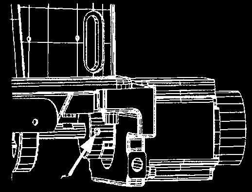
7 . Configuration of the machine E D K G I F J C H A The APW-895 consists mainly of the following units. A Frame and structural components (Frame sewing table, covers, foot switch, etc.) Clamp foot unit and feed mechanism C Corner knife unit D inder unit (inder components and its driving components) E Pneumatic control unit (Pneumatic control devices and pipings) F Stacker unit (Optional) G Sewing machine head H Electric control unit (Control panel) I Operation panel J Power switch K Temporary stop switch With this machine consisting of the aforementioned 11 units, you can do desired welting work simply by setting materials (garment body, interlining piece, welting patch, etc.) in place and operating the switches on the operation panel. In addition, when temporary stop switch K is pressed during operation of the device, tthe device stops.


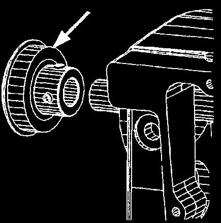
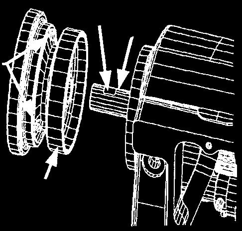


8 3. Standard Adjustment (1) Machine head 1) How to change the timing belt Standard Adjustment Flat Arm hole 0.5mm Driving Arm inner diameter Parts no. : No. 1 screw Up dead position Flat in front Flat 3
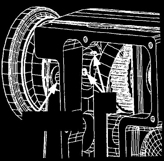
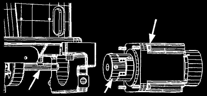
9 Adjustment Procedures Results of Improper Adjustment 1. Remove the four set screws of the motor.. Loosen the two set screws of the coupling. 3. Remove the motor and coupling from the lower shaft. 4. Remove the six set screws, and remove the window plate. 5. Remove the timing belt from the pulley. 6. Loosen the two setscrews from arm hole. 7. Loosen the two setscrews of the pulley, and remove the pulley. 8. Tap the rear bearing from inside and pull out this rear bearing. 9. Pass the timing belt through the bearing hole of the arm and remove (pull out) the timing belt via the main shaft. 10. Install a new timing belt. 11. Degrease the outer diameter of the rear bearing and the inner diameter of the arm, apply a sealant of medium or higher strength, and drive the rear bearing until it stops in the interior. 1. Tighten two setscrews from the armhole. (There is no flat section.) 13. Join the flat section of the main shaft with the first screw of the pulley, and mount the pulley. At that time, the clearance should be about 0.5mm between the pulley and the arm. 14. Turn the pulley and let the needle bar stay in the UP dead position. At that time, the timing belt is hung in the position where the flat section of the lower shaft faces the front. 15. Join the flat section of the lower shaft with the first screw of the coupling, and tighten two setscrews. 16. Tighten four motor setscrews to fix the motor. 17. Fix the window plate with six setscrews. 4


 Front")


10 ) Adjustment of needle bar height Standard Adjustment Lower dead point marker of needle bar lindstitch marker of hook blade tip 3) Front or rear adjustment of needle bar rocking base Standard Adjustment Eccentricity Origin position 5
11 Adjustment Procedures Results of Improper Adjustment 1. Turn the pulley until the needle bar comes to the lower dead point.. Loosen the needle bar connection screw. 3. ased on the upper engraved marker line of the needle bar lower dead point, tighten the needle bar connection screw. 4. The needle shall be positioned in the center of the throat plate hole. Adjustment Procedures Results of Improper Adjustment 1. When the motor shaft is rotated, the needle bar rocking link makes a rocking motion by the effect of the eccentric cam.. Turn the power OFF, rotate the motor shaft, and confirm that the needle makes a uniform rocking motion in the oblong hole of the throat plate. 3. If the needle motion is not uniform, insert a tool from the hole on the top surface of machine arm and loosen the needle bar rocking arm setscrew for adjustments. 4. In the case of eccentricity to the left, confirm whether the sensor slit is located in the edge position of the sensor. 5. In the case of deflection, loosen the sensor slit setscrew or the sensor setscrew for adjustments. * For fine adjustments, use of the sensor setscrew is adequate. 6. After the power is ON, the needle comes in the center of the throat plate hole. To make sure, examine [(11) Needle and Hook Timing Adjustments and (1) Needle and Hook Clearance Adjustments] (Hook Adjustment). 6
12 4) Adjustment of mounting position for needle thread trimming unit Standard Adjustment 5mm Clearance 30 to 3mm 5) Adjustment of needle thread trimmer sharpness Standard Adjustment 6) Replacement of needle thread knife Standard Adjustment Same surface 7
13 Adjustment Procedures Results of Improper Adjustment The knife is driven by the air cylinder. Therefore, relieve the air pressure before adjustments. 1. Loosen two setscrews and maintain the clearance toward the throat plate at 5mm in the state that the moving knife is advanced to the extreme front. Adjust the distance toward the needle to 30 to 3 mm and tighten the two setscrews. In this case, confirm that a proper clearance is secured between the center knife and the spreader. Adjustment Procedures Results of Improper Adjustment 1. Loosen two setscrews of the counter knife and push both right and left blades of the counter knife uniformly against the moving knife. Then tighten the two setscrews again.. Check the motion of the cylinder shaft. Confirm that it can work to accomplish cutting assuredly at 17.6N (1.8kgf) or less. 3. After thread cutting, the holding force for needle thread clamp is more than.9n (300g) both right and left. In the case when this force is not secured, select an adequate spacer. [The spacer has four types of thickness: 0.mm, 0.4mm, 0.6mm, and 0.8mm] Adjustment Procedures Results of Improper Adjustment 1. Loosen the setscrew and remove the pin. Then, the moving knife can be pulled off downwards.. Install a new moving knife and insert the pin. At that time, the pin should be held almost in the same plane of the moving knife. Tighten the setscrew. * The needle thread trimming unit has some mounting parts that can change with the gauge size. Refer to the table below for details. No. Size Name of parts 8mm 10mm 1mm 14mm 16mm 18mm 0mm mm 4mm 6mm 8mm 30mm 3mm 1 Counter knife Moving knife Clamp plate
14 7) Adjusting the bobbin thread trimming knife Standard Adjustment A 9
15 Adjustment Procedures Results of Improper Adjustment 1. How to join the throat plate and the bobbin thread trimming knife (1) Hold the bobbin thread trimming knife perpendicular to the throat plate. Install it to avoid any twisting motion during operation. () Loosen the setscrew of the left bobbin thread trimmer and actuate the bobbin thread trimmer knife cylinder. (3) Loosen the setscrew of the right bobbin thread trimmer and actuate the bobbin thread trimmer knife cylinder. (4) Set the left bobbin thread trimmer base where the bobbin thread trimming knife does not cause twisting motion, and fix the setscrew. (5) Set the right bobbin thread trimmer base where the bobbin thread trimming knife does not cause twisting motion, and fix the setscrew.. Adjustment of bobbin thread trimming knife position and height (1) Join the upper surfaces of both right and left bobbin thread trimming knives with the upper surface of the throat plate in the same plane. Make adjustments so that the groove of throat plate meets in parallel to that of the bobbin thread trimming knife when the bobbin thread trimmer is actuated. () Loosen the setscrew of the left bobbin thread trimmer and make adjustments so that the upper surfaces of the throat plate and the bobbin thread trimming knife are joined in the same plane. (3) Loosen the setscrew of the right bobbin thread trimmer and make adjustments so that the upper surfaces of the throat plate and the bobbin thread trimming knife are joined in the same plane. (Caution) e aware that the bobbin thread trimming knife should be below the top surface of the throat plate. (4) Push the bobbin thread trimming knife cylinder of the left bobbin thread trimmer in Direction A and adjust its position so that the groove of the bobbin thread trimming knife meets in parallel to that of the throat plate. (5) Push the bobbin thread trimming knife cylinder of the right bobbin thread trimmer in Direction and adjust its position so that the groove of the bobbin thread trimming knife meets in parallel to that of the throat plate. (6) Tighten the right and left setscrews and. 3. Replacement of the bobbin thread trimming knife (1) When the setscrews and are loosened, the right and left bobbin thread trimming knives can be pulled off downwards. 4. Adjustment of bobbin thread trimming knife sharpness (1) Adequately push the thread clamp pushing spring against the bobbin thread trimming knife to adjust its sharpness. () The pushing force should be kept as light as possible, to a degree the thread can be cut assuredly. Then, the 10
16 8) Height adjustment of center knife Standard Adjustment Knife bar connection Screw hole 0 to 0.3mm 9) Adjustment of center knife link Standard Adjustment Tightening screw hole Level Metal 11
17 Adjustment Procedures Results of Improper Adjustment Relieve the air pressure during adjustment. 1. Insert a tool from the hole of the knife bar connecting screw and loosen the knife bar connecting setscrew.. Turn the motor shaft to move the center knife to the lower dead point. At that time, tighten the knife bar connecting setscrew where the throat plate and the center knife assume a condition of 0 to 0.3mm as illustrated. Adjustment Procedures Results of Improper Adjustment 1. Remove the four set screws, and remove the face plate.. Confirm that Link A is maintained level at the lower dead point of the center knife. 3. If the horizontality of Link A is not secured, insert a tool from the tightening screw hole and loosen the driving arm tightening screw. Where Link A is maintained level, tighten the driving arm tightening screw again. At that time, the driving arm should have been moved to the metal side during screw tightening. 1
18 10) Adjustment of center knife motion stop Standard Adjustment Coincidence of shaft centers Withdrawn Protruded 11) Timing adjustment of needle and hook Standard Adjustment Needle lade point 1.3±0.mm lade point 3.5mm Lifting position 0 to -0.05mm 0 to 0.03mm 13
19 Adjustment Procedures Results of Improper Adjustment 1. While the cylinder is withdrawn, the knife bar is in the state of motion. While it is protruded, the knife bar remains in the state of stop.. While this cylinder is protruded, confirm that the shaft center of Link A coincides with that of Screw A. 3. If no coincidence is perceived, loosen the nut of the adjusting screw and adjust the adjusting screw to the position where the shaft centers coincide with each other. When coincidence is secured, fix the nut. Adjustment Procedures Results of Improper Adjustment 1. Timing adjustment of the needle and hook (1) Remove the throat plate. When the needle is raised by 3.5mm from the lowermost point (needle bar engraved line alignment), let the blade points of the right and left hooks coincide with the needle centers. At that time, the clearance between the needle side surface and the hook holder shall be 0 to -0.05mm, the clearance between the needle side surface and the blade point shall be 0 to 0.03mm, and the distance between the upper end of the needle hole and the blade point shall be 1.3±0.mm.. Adjustment of hook timing (1) Loosen three setscrews of small gears located on the hook shaft and turn the hook. When the needle center coincides with the blade point, tighten the setscrews. In this case, the three setscrews should be tightened in the specified order. To avoid the occurrence of vertical rattling in the hook shaft, try to tighten the setscrews while the hook is pushed down and the small gears are somewhat raised. () Check whether the main shaft torque is applied after adjustment of the hook timing. 14
20 1) Adjustment of clearance between needle and hook 13) Installing and removing of hook 14) Opener adjustment Standard Adjustment 0. to 0.3mm 15
21 Adjustment Procedures Results of Improper Adjustment Adjustment of clearance between needle and hook s blade point 1. Loosen the setscrews and of the hook shaft base on the adjusting side.. Move the hook shaft base to the right and left and adjust the clearance between the needle and hook s blade point to 0 to 0.03mm. Then tighten the setscrews and. At that time, the setscrew should be tightened rigidly while the setscrew is tightened properly. (Caution) The setscrew is tightened with the lower shaft connected. It must be noted that the rotary torque of the lower shaft may be increased if the setscrew is tightened too much. Removing the hook 1. Remove the throat plate.. Remove the opener. 3. Loosen the three setscrews of the hook shaft small gear. 4. Turn the hand wheel so that the needle bar comes to the highest position. Since then, remove the hook. Installing of the hook 1. Reassembly can be carried out in the reverse order for disassembly. (Caution) 1. When the hook is installed, confirm that the washer is inserted in between the hook shaft lower metal and the hook shaft small gear.. When mounting the throat plate, turn the inner hook by hand so that its embossed part is entered in the groove of the throat plate. Since then, mount the throat plate. Opener adjustment 1. Turn the hand wheel in regular direction and loosen the setscrew of the inner hook guide for adjustments so that the clearance between the inner hook guide and the embossed part of the bobbin case is adjusted to 0. to 0.3mm when the inner hook guide is moved to the farthest retreat position in the direction of the arrow. (Caution) Clearance checks and adjustments should be done after the final retreat positions of the right and left inner hook guides have been confirmed. 16
22 15) Wiper adjustment Standard Adjustment A D F 1±1mm 5±1mm mm E C 17
23 Adjustment Procedures Results of Improper Adjustment 1. Positioning adjustment of wiper unit (1) Loosen the wiper unit setscrew to adjust the unit overall so that the clearance between wiper s lower end surface C and the head section D attains 1 ± 1mm when the wiper cylinder is actuated.. Adjustment of wiper stroke (1) Loosen the fixing nut of the wiper stopper and move the wiper stopper in Directions A and. o Direction A Wiper stroke is decreased. o Direction Wiper stroke is increased. () After wiper stroke adjustments, tighten the fixing nut of the wiper stopper and fix the wiper stopper. (Caution) If the stroke is changed, the clearance is also changed between wiper s lower end surface C and the head section D when the wiper cylinder is returned. Therefore, loosen the wiper unit setscrew to adjust the unit overall so that the clearance between wiper s lower end surface 0 E and the head section F attains 1 mm. 0.5 o If the amount of wiper motion is small, unthreading will be caused at the sewing start. o If the amount of wiper motion is large, poorly tense stitches may occur at the sewing start. 18


")


24 16) Hook oil amount Standard Adjustment (1) Adjustment of hook oil amount Oil amount decreases Oil splashed Oil amount increases Minimum Maximum () Cleaning of the filter section Plunger To the hook shaft base To oil tank (3) Setting for hook oil amount check H F C D G A E 19
25 Adjustment Procedures Results of Improper Adjustment (1) Adjustment of hook oil amount 1. Adjust the oil amount by means of the oil amount adjusting screw that is attached to the hook shaft base.. When the oil amount adjusting screw is turned clockwise, the oil amount increases. When it is turned counterclockwise, the oil amount decreases. 3. Measure the oil amount in 5 seconds. If the oil amount is too less, this can be a cause of malfunction. For oil amount check, be sure to observe the oil amount in the hook race section. 4. Adjust the oil amount so that it is not lower than the minimum level (as illustrated). [For reference] When adjustment of hook s oil amount is intended, it is necessary to raise the sewing machine first of all. In regard to the method of raising the sewing machine, refer to the Instruction Manual "VII-5 How to lay down the sewing machine". e sure to perform the measurement after putting the sewing machine in the storage position. o If the oil amount lowers below the minimum level, this can be a cause of problems such as hook abrasion, seizure, and so on. () Cleaning of the filter section Periodically (approximately once every 3 months), clean the filter sections and ( positions). 1. Loosen the setscrew of the lubrication tube holder for removal from the bed.. Loosen the pipe stopper to take out the tube and the joint. 3. After the removal of dust attached to the net area of the joint, recover the initial state. (3) Setting for hook oil amount check 1. Display the check program menu screen. When the key is kept pressed for 3 seconds, a check program button (A) is displayed in the screen. When this button is pressed, the check program menu screen is displayed.. IO1 head aging mode Press the head aging button () in the check program menu screen to display the head aging screen. C: Used to set up the number of head revolutions. Set 500 revolutions. D:Used to set up the revolving time. Set 5 seconds. E:Used to set up the stop time. The stop time can be set up arbitrarily. Set up any stop time as you like. F : Used to select whether the center knife is driven in interlinkage with the sewing machine. It is very dangerous if the center knife is driven in the middle of hook oil amount check. This check shall be done in the state of power OFF, without fail. G: Used to start the revolution of the machine head. The revolution stops when it is pressed again. H:Used to return to the menu. (Effective only in the middle of revolution stop) 0
26 17) Adjustment of thread take-up spring Standard Adjustment 1.When changing the amount of motion for the thread take-up spring Stroke : 14±mm.When changing the strength of the thread take-up spring Thread take-up spring tension: 1mm 0.5N (5g) Thread take-up spring tension: 1mm 0.5N (5g) Stroke : 14±mm 1
27 Adjustment Procedures Results of Improper Adjustment 1. When changing the amount of motion for the thread take-up spring (1) To adjust the right thread take-up spring, loosen the second thread tension setscrew and turn the second thread tension (asm.) to the right and left. () To adjust the left thread take-up spring, loosen the second thread tension setscrew and turn the second thread tension (asm.) to the right and left. (3) When the second thread tensions (asm.) and are turned to the right, the thread take-up amount (stroke) is increased. When it is turned to the left, the thread take-up amount becomes small. (4) Make sure that the strokes of the thread take-up springs and are 14 ± mm when the thread is pulled downward. (Caution) When the second thread tension setscrews (left) and (right) are loosened, the amount of disk floating may become change. Check "18) Adjustment of floating amount of the thread tension disk" again.. When changing the strength of the thread take-up spring (1) When changing the strength of the right thread take-up spring, turning the spring shaft to the right causes the strength to increase and turning it to the left causes the strength to decrease. () When changing the strength of the left thread take-up spring, turning the spring shaft to the right causes the strength to increase and turning it to the left causes the strength to decrease. Standard adjusting values (3) Make sure that the tensions of the thread take-up springs and are 0.5 N (5g) when the thread is pulled 1 mm sideward and slightly upward.
28 18) Adjustment of floating amount of the thread tension disk Standard Adjustment A Same surface 3
29 Adjustment Procedures Results of Improper Adjustment 1. Standard adjustment is to obtain the same plane where the end surface of the disk floating cylinder and disk floating cylinder fixing nut are included.. The amount of thread tension disk floating is 1.0 to 1.5mm. (1) Remove the fixing plate setscrew of the disk floating cylinder and take out the disk floating unit. () Loosen the fixing nut of the disk floating cylinder and move the disk floating cylinder in the direction of the arrow. Adjustment of the disk floating cylinder : o Moving it in Direction A causes the amount of disk floating to increase. o Moving it in Direction causes the amount of disk floating to decrease. Reassembly can be carried out in the reverse order for disassembly. 4
30 19) Adjustment of the bobbin thread remaining amount detection Standard Adjustment 1.Sensor lateral direction Sensor indicator: OFF stability display: Lit in green (Orange unlit) ON stability display: Lit in green and orange (oth unlit or lighting in orange only indicates an unstable condition.).adjustment of the sensor lateral direction 3.Method of sensor check Groove section A 5
31 Adjustment Procedures Results of Improper Adjustment 1. Sensor lateral direction (1) Loosen the sensor setscrew, and adjust the lateral direction to the direction of arrow mark.. Adjustment of the sensor lateral direction (1) Loosen the setscrew of the mounting plate, and adjust the sensor lateral direction. * Sensor adjustments are the same for both right and left. 3. Method of sensor check (1) Wind a small amount of thread around the bobbin (to a degree bobbin s groove section is covered) and set the bobbin in the bobbin case. (Pass the thread through the bobbin case as making ordinary stitches.) () Turn the hand wheel of the sewing machine to assume the needle bar stop position (upper dead point of the needle bar thread take-up lever). (3) Set a bobbin case in the inner hook and slowly pull out the thread until the bobbin reflector seal taps the sensor s optical axis section. When the sensor is actuated at that time and the sensor indicator light is lit in orange, this is the sign for the completion of adjustments. (4) To confirm whether the sensor performs detection assuredly even when the bobbin case is moved to the right and left at that time, try to turn the bobbin once to assume that the sensor indicator light is lit in green only and push the bobbin case with a finger in Direction A so that the bobbin reflector seal coincides with the sensor s optical axis section. Check the status of the sensor indicator light in this manner. Turn the bobbin again and push it in Direction further in order to examine the status of the sensor indicator light. 6
32 0) Lower shaft area Standard Adjustment 1.Adjustment of the lower shaft gear Mounting direction of the spacer Hook shaft base.replacement of the lower shaft A Plunger groove A L R 7
33 Adjustment Procedures Results of Improper Adjustment 1. Adjustment of the lower shaft gear (1) Pinch the lower shaft gear between Spacer A and Spacer. Press the gear holder in the direction of the arrow (hook shaft base side). Make rattle adjustments in thrust direction. (Caution) Rattles in thrust direction may be adjusted to zero. However, too much pressing may result in very much sound or heat generation around the lower shaft. () After adjustments, fix the lower shaft fixing screw. (3) Make similar adjustments for gears on opposite side. If there is any rattling in thrust direction, the following difficulties may arise: o Rattles may increase in the direction of hook rotation. This can be a cause of sewing deficiency. o Noise and heat generation may be increased.. Replacement of the lower shaft (1) Since the right and left lower shaft gears of the lower shaft are manufactured in a set, the lower shaft should be replaced, as required, together with the lower shaft gears in a set. (Set part No.: ) () The lower shaft face and the gear face have their appropriate directions of assembly. Conform to the assembly diagram. * When plunger groove is positioned downwards o the engraved marking L of the left-side lower shaft gear comes to lower side as the lower shaft gear is seen from Direction A. o the engraved marking R of the right-side lower shaft gear comes to lower side as the lower shaft gear is seen from Direction. (Caution) The spacer comes in the shape of the step washer. For assembly, the wider side of the washer face should be positioned on the hook shaft base side. 8
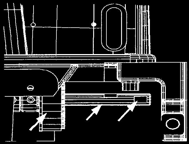
34 () Unit and related sections 1) inder adjustments Standard Adjustment When the pedal switch is trodden on to the third grade, the air cylinder begins to be driven and the binder lowers to the section between the right and left clamp foot. After the completion of sewing and corner knife actuation, the binder is raised at the end of backward return by the return action of the air cylinder until its original position is recovered. 9
35 Adjustment Procedures Results of Improper Adjustment 1. Adjustment of parallelism between slide base side face and machine head side face (1) In the first place, loosen the fixing screw of the lock base. Since then, deflect the entire slide base in the direction of the arrow, around the center of the pivot shaft, in order to secure the parallelism between side face of the slide base and that of the machine head. After parallelism adjustments, tighten the fixing screw assuredly. 30
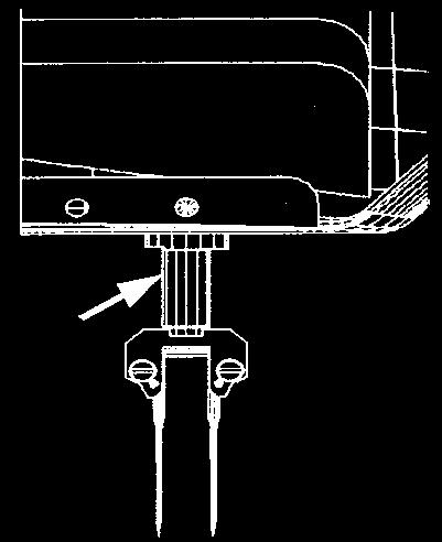
36 Standard Adjustment. Adjustment of binder fall position When the stitch width is 10mm 10mm inder 0.5 to 1.0mm 5mm 5mm Sewing table inder fulcrum shaft Sewing machine needle 5±0.5mm INDER_FITING_ASE 31
37 Adjustment Procedures Results of Improper Adjustment. Adjustment of binder fall position (1)Turn off the power supply. Push the binder by hand in the direction of the arrow to lower the binder. () The sewing machine needle shall be regarded as a standard. The condition is regarded as normal if the binder lowers to the symmetrical position of right and left where the welting patch scale does not come in contact with the sewing machine needle. (3) If the welting patch scale is not symmetrically balanced with reference to the needle fall line, loosen the setscrew securing the binder mounting base and the screw securing the thrust collar and adjust the position of the binder in the right-left direction. After adjustments, let the thrust collar contact the binder mounting base and tighten the respective screws and. (4) The dimension from the needle settle position to the rear end of the welting patch scale shall be approximately 5 ± 0.5mm. (5) If the above-mentioned dimension is not secured, loosen the fixing screw of the INDER_FITTING_ASE_. Move the INDER_FITTING_ASE_ in the direction of the arrow for adjustments. After adjustments, tighten the fixing screw assuredly. 3
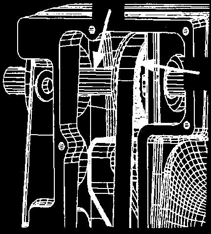
38 Standard Adjustment 3. Adjustment of concentricity between 4. Adjustment of binder levelness pocket bag scale and needle center 1mm 1mm 5. Adjustment of materials guide 0.5 to 1.0mm 0.1 to 0.6mm 33
39 Adjustment Procedures Results of Improper Adjustment 3. Adjustment of concentricity between welting patch scale and needle center (1) After the fixing screw has been loosened, let the entire binder deflect in the direction of the arrow to secure the concentricity of the needle center. After concentricity adjustments, tighten the fixing screw assuredly. (Caution) This adjustment is also needed when the parallelism is adjusted between the welting patch scale and the clamp feet. 4. Adjustment of binder levelness Similarly as for adjustments of fall position and concentricity, adjust and confirm the horizontality (also horizontality of the welting patch scale and the sewing table ). (1) Similarly as for the adjustment of the fall position, manually lower the binder. () Assume the conditions such that the distance becomes 1mm between the lower face of the welting patch scale and the upper face of the sewing table at the bottom end, and that horizontality can be secured. (However, the difference between front and rear ends of the welting patch scale shall be 0.3mm or less.) (3) For horizontality adjustment, loosen the fixing screw of the binder mounting base and deflect the entire binding in the direction of the arrow, around the center of the binder pivot shaft, in order to secure the horizontality. After the adjustment of horizontality, tighten the fixing screw securely. (4) For the adjustment of clearance (1mm) between the lower face of the welting patch scale and the upper face of the sewing table, try to turn the cylinder sahft as illustrated. Loosen the lock nut and turn the cylinder shaft in the direction of tightening the shaft onto the cylinder joint to let the welting patch scale rise or in the direction of loosening the shaft to let the scale fall. When a clearance of 1mm has been secured, tighten the lock nut assuredly. 5. Adjustment of materials guide The material guide allows a welting patch to become stable at the edge of the needle during sewing. When the stitch size is changed, readjustments are always needed. (1) Loosen the fixing screw of the material guide arm and move the arm to the side of the needle. The clearance between the side face of the needle shank section and that of the material guide shall be 0.1 to 0.6mm. () At that time, the material guide spring shall be effective such that the material guide arm is lightly pressed and there is no unreasonable resistance at the time of material passing. The pressing pressure of the material guide spring can be adjusted by the screw. (3) The clearance between the material guide and the welting patch scale shall be kept around 0.5 to 1.0mm (welt cloth thickness). It can be adjusted by means of the screw after loosening the lock nut. After adjustments, tighten the lock nut securely. 34
40 ) Clamp foot operation Standard Adjustment Unilateral/bilateral welt changeover cylinder Slide base Unilateral/bilateral welt changeover cylinder Folding cylinder Folding cylinder Flap presser Flap presser 35
41 Adjustment Procedures Results of Improper Adjustment 1. y the action of the right-side clamp foot cylinder caused by pedal switch tread-on operation, the right-side clamp foot lowers. When the left-side clamp foot cylinder is actuated, the left-side clamp foot lowers to complete the garment body clamp.. In the case of flap sewing, set the right or left flap material and tread on the pedal switch. Then, the flap presser cylinder is actuated to clamp the flap in the specified position. 36
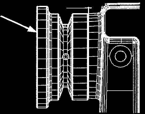
42 3) Tension adjustment of clamp foot feed belt 4) Stop position adjustment for forward end or backward end of clamp foot feed Standard Adjustment 3) Tension adjustment of clamp foot feed belt 10.±0.98N 9.4mm 4) Stop position adjustment for forward end or backward end of clamp foot feed ackward end position 155mm Needle center 315mm Forward end position 30mm 80mm 0mm 15mm For origin sensing For step-out sensing 37
43 Adjustment Procedures Results of Improper Adjustment 3) Tension adjustment of clamp foot feed belt 1. Loosen the lock nut, and adjust the tension with the tension screw.. When a pressing force of 10.± 0.98N is applied to the center of the pulley, exert a tension to a degree where a deflection of 9.4mm is caused. 3. After adjustments, tighten the lock nut firmly. 4) Stop position adjustment for forward end or backward end of clamp foot feed 1. Stop position of forward end or backward end (1) Decision is based on the position of the photo sensor as illustrated. ased on the reference dimension of the position of the photo sensor, determine the clamp foot stop position as illustrated. o For the clamp foot forward end, the garment body clamp tip shall be positioned 315mm from the needle center. o For the clamp foot forward end, the garment body clamp tip shall be positioned 155mm from the needle center. () When the origin detection sensor is ON, the clamp foot advances by 30mm and then stops. (3) If the dimensions are not as shown in the figure, loosen the lock nut, and turn the stopper screw to adjust the dimensions. In addition, loosen the setscrew, adjust the position of the photo sensor.. Position adjustment of the photo sensor (1) There shall be no interference in the clearance between the clamp foot proximity switch (photo sensor ) and the detector plate, and around the clamp foot proximity switch (photo sensor ) and the detector plate. 38
44 5) Positioning adjustment of welting patch folding plate 6) Adjustment of parallelism of welting patch folding Standard Adjustment 5) Positioning adjustment of welting patch folding plate Sewing machine needle Left folding plate Right folding plate 1.5 to.0mm 1.5 to.0mm 6) Adjustment of the parallelism of welting patch folding Position of 0mm movement 39
45 Adjustment Procedures Results of Improper Adjustment 5) Positioning adjustment of welting patch folding plate 1. If the dimension is inadequate as illustrated, loosen the setscrew and move it in the direction of the arrow for adjustments. 6) Adjustment of the parallelism of welting patch folding 1. When it is moved by 0mm from the clamp foot forward end, the difference between the needle center and the folding end face shall be 0.15mm or less.. If the parallelism is not secured, loosen the setscrew for adjustments. 40
46 7) Positioning adjustment of right and left garment body clamp 8) Adjustment of parallelism of right and left garment body clamp and welting patch scale Standard Adjustment 7) Positioning adjustment of right and left garment body clamp 1.3±0.mm 1.3±0.mm 8) Adjustment of parallelism of right and left garment body clamp and welting patch scale 41
47 Adjustment Procedures Results of Improper Adjustment 7) Positioning adjustment of right and left garment body clamp If the dimensions as specified in the illustration are not secured: o For bilateral type, adjust it by turning the ratchet knob. o For unilateral type, adjust it by turning the ratchet knob. 8) Adjustment of parallelism of right and left garment body clamp and welting patch scale 1. When it is moved by 0mm from the clamp foot forward end, the difference between the welting patch scale and the end face of the left garment body clamp and right garment body clamp shall be 0.15mm or less.. If the parallelism is not secured, loosen the fixing screw for adjustment by lowering the serge back clamp. 4
48 9) Adjustment of released presser height 10) Positioning adjustment of the flap presser 11) Positioning adjustment of flap scale and flap stopper Standard Adjustment 9) Adjustment of released presser height Garment body clamp 5±1mm Top surface of sewing table 10) Positioning adjustment of the flap presser 6.5±0.5mm 11) Positioning adjustment of flap scale and flap stopper 43
49 Adjustment Procedures Results of Improper Adjustment 9) Adjustment of released presser height 1. If the dimensions is not 5 ± 1 mm unlike the drawing, loosen the nut securing the clamp foot cylinder and adjust the screwing amount into the elevating block. 10) Positioning adjustment of the flap presser 1. If the dimensions is not 6.5 ± 0.5 mm unlike the drawing, loosen the setscrew and adjust the position of the flap presserr. For this adjustment, however, never fail to adjust the parallelism for the folding plate and the flap presser. 11) Positioning adjustment of flap scale and flap stopper 1. In conjunction with the flap length, loosen the setscrew of the flap scale for adjustment. The flap stoppers (A) and () used to set up the flap materials shall be mainly adjusted by loosening the setscrew according to the condition of pattern arrangement for the serge back materials and flap materials. 44
50 1) Corner knife mechanism Standard Adjustment [Corner knife operation] 1. When the corner knife moving motor A is turned ON, the moving-side corner knife (position of sewing start) moves to the position that is proportionate to the preset sewing length.. At the end of movement, the moving-side corner knife and the fixed-side corner knife C (position of sewing end) begin to be raised by the respective elevator air cylinders D and E to cut the material. A C D E 45
51 Adjustment Procedures Results of Improper Adjustment 1. In the case of corner knife replacement and adjustment, draw out the corner knife unit before adjustments.. After completion of the adjustment, be sure to conduct the tests sufficiently to ensure that no defective cutting occurs before regular operation. 46
52 13) Height adjustment of corner knife 14) Tension adjustment of corner knife feeding belt Standard Adjustment 13) Height adjustment of corner knife 5±0.5mm 14) Tension adjustment of corner knife feeding belt 4.4mm 4.6±0.6N Oblong hole Drive-side pulley 47
53 Adjustment Procedures Results of Improper Adjustment 13) Height adjustment of corner knife 1. Make adjustments by loosening the fixing screw so that the tips of both moving and fixed corner knifes are positioned about 4.5 to 5.5mm from the table upper face to the knife holder upper face at the rising end of the corner knife elevator cylinder, as illustrated. 14) Tension adjustment of corner knife feeding belt 1. Loosen the fixing screw and the lock nut and move the follower side pulley along the oblong hole of the base. (y moving the adjusting screw forward and backward, the follower side pulley can be moved.). When a pressing force of 4.6± 0.6N is applied to the center of the pulley, exert a tension to a degree where a deflection of 4.4mm is caused. 3. After adjustments, tighten the fixing screw and the lock nut assuredly. o If the tension is too weak, the sewing and knife positions may give rise to deviation. 48
54 15) Adjustment of origin position of corner knife Standard Adjustment [Origin position of the moving and counter corner knife] 5±1mm Needle center 145±1mm ±1mm A±1mm G Gauge size (mm) A Assemblying dimensions (mm) Assemblying dimensions (mm) Counter corner knife Moving corner knife Origin sensing photo switch Origin detector plat 49
55 Adjustment Procedures Results of Improper Adjustment 1. If the dimensions as specified in the illustration are not secured, loosen the setscrew for adjustment.. If the dimension of the fixed corner knife cannot be secured even after the adjustment by loosening the setscrew, try to loosen the setscrew for another adjustment. 3. If the dimension of the moving corner knife cannot be secured even after the adjustment by loosening the setscrew, try to loosen the fixing screw and shift the switch mounting bracket for adjustment. 50
56 16) Centering adjustment of corner knife 17) Adjustment of corner knife right and left bends Standard Adjustment 16) Centering adjustment of corner knife Needle center Movement of 0mm Locus of corner knife movement Sewing machine needle A deflection of 0 ± 0.5mm per movement of 0mm 17) Adjustment of corner knife right and left bends Failure Normal 0 to 1.0mm Stitch Stitch 0. to 1.mm 51
57 Adjustment Procedures Results of Improper Adjustment 16) Centering adjustment of corner knife 1. The center of corner knife movement is required to coincide with the needle center.. This adjustment has been already finished at the time of shipment from the factory. However, in such a case when the corner knife unit is moved for reasons of external shocks or others, some adjustments are needed in the steps described below so that deviation from the needle center can be kept within 0 ± 0.5mm even when the moving corner knife is moved by about 0mm. (1) Loosen the fixing screws and, fix the corner knife unit with the toggle clamp, and adjust the frame bracket so that the center of corner knife movement is maintained in parallel to the needle center. (Fine adjustments can be made by loosening the lock nut and shifting the adjusting screw forward and backward.) () Shift the guide plate to make the positioning pin enter the hole and tighten the fixing screw. (3) Loosen the fixing screw and make adjustments by shifting the switch bracket so that the corner knife unit opening sensor switch can detect the presence of opening. 17) Adjustment of corner knife right and left bends 1. The corner knife shall be adjusted so that it cuts the center of the sewing line and that the thread is not cut off. If "16) Centering adjustment of corner knife" has been duly finished, the corner knife may be mounted to make fine adjustments. o If the corner knife is deflected to the right or left, or fastened in a bent posture, malfunction as illustrated may occur. 5
58 18) Adjustment of parallel sewin 19) Fine adjustments for stitches Standard Adjustment 18) Adjustment of parallel sewin Approx. 5mm Corner knife lade tip G G: Needle width Knife holder groove section 19) Fine adjustments for stitches 53
59 Adjustment Procedures Results of Improper Adjustment 18) Adjustment of parallel sewin 1. ecure the corner knife holder with setscrew cso that the opening amount of the holder is set to approx. 5 mm.. Insert the corner knife in the groove section of the corner knife holder and secure the blade position where the width of the blade tip attains an approximate needle size G. In this position, turn the eccentric pin in the direction of the arrow and fix it. After completion of the setting described above, perform trial sewing with use of sewing material. 19) Fine adjustments for stitches 1. To adjust the cut section length, loosen the eccentric pin and move the corner knife in the direction of the arrow. (Caution) During the above-mentioned moving adjustments, the blade tip section should be positioned where it is covered.. For the adjustment of the cut section angle, loosen the setscrew and adjust the amount of opening of the corner knife holder. 54
60 0) Pedal and related sections Standard Adjustment A A 55
61 Adjustment Procedures Results of Improper Adjustment 1. Adjustment of pedal ball plunger (1) Loosen the pedal ball plunger fixing nut and adjust the position of the pedal ball plunger in the arrow direction (A or ). o The pedal click is strengthened when the pedal ball plunger is moved in Direction A. o The pedal click is weakened when the pedal ball plunger is moved in Direction. () Use the pedal ball plunger fixing nut for fixing. (Caution) 1. The pedal ball plunger is made of plastics. e aware that tightening the plunger fixing nut excessively may damage the plunger.. Adjust the main body of the pedal ball plunger so that it is not protruded from the end face of the pedal lever. 3. The plunger ball only is allowed to be protruded from the end face of the pedal lever.. Adjustment of the pedal lever support plate (1) To prevent the pedal lever from rattling in the direction of the arrow, loosen the pedal lever support plate setscrew and move the pedal lever support plate in the direction of the arrow for adjustment. (Caution) 1. A pedal return error may occur if the pedal lever does not move smoothly throughout the stroke range.. The pedal click is weakened if the pedal lever has a rattling problem in the arrow direction (A or ). 3. Adjustment of ball plunger hole position (1) Loosen the pedal lever fixing screw and align the mounting tap of the pedal ball plunger of the pedal lever with the plunger hole of the pedal base. 56
62 1) Marking light and related sections Standard Adjustment 1. Adjustment of laser beam parallelism of the marking light Sewing machine needle 80mm Movable range of 0mm Parallelism not secured Sewing machine needle Fig. A Deviation in right and left directions Sewing machine needle Fig. Vertical laser beam Vertical laser beam. Adjustment of the light value of the marking light From the rear side of the marking light Wiring for the marking light 57
63 Adjustment Procedures Results of Improper Adjustment 1. Adjustment of laser beam parallelism of the marking light (1) Adjustment of the horizontal line o If parallelism of the laser beam is not secured, loosen the setscrew and turn the marking light A for adjustment. o In the case of adjustments at the panel beyond the range of origin correction (±5mm), dislodge the marking light cover and loosen the setscrew of the rear sensor plate. In this state, turn the sensor plate for adjustment. () Adjustment of vertical line position o If parallelism of the vertical laser beam is not secured (See Fig. A), loosen the setscrew and turn the marking light for adjustment. o If the vertical laser beam has deviated in the right or left direction (See Fig. ), loosen the hinge screw and adjust the marking light by turning it around the center of the hinge screw. o If the radiation range (300mm from the needle center) of the vertical laser beam is not secured, loosen the setscrew and turn the marking light for adjustment around the center of the fixed shaft.. Adjustment of the light value of the marking light (1) The light value of the marking light is adjusted with the volume control located on the rear side of the marking light. o The laser beam is lightened when the volume control is turned to the right. o The laser beam is darkened when the volume control is turned to the left. 58
64 (3) Optional sections 1) SA-117 (dart stretcher unit) Standard Adjustment 1. Installation A. Adjustment 59
65 Adjustment Procedures Results of Improper Adjustment 1. Installation (1) Install the darts stretcher unit on the base by means of two setscrews. () Insert the tube in Joint A and the tube in Joint.. Adjustment (1) Loosen and adjust the adjusting screw until the darts holding rubber fits the sewing table hole. 60
66 ) SA-118 (shim unit) Standard Adjustment 1. Installation of the shim bracket 61
67 Adjustment Procedures Results of Improper Adjustment 1. Secure the shim bracket ( ) to the shim base ( ) with the screws (SL605169TN).. Secure the cylinder (PA A0) to the pocket bag clamp cylinder bracket ( ) with a screw and tighten the pocket bag clamp cylinder rod ( ) onto the cylinder shaft. Mount the speed controller (PC ) on the cylinder. 3. Secure the pocket bag clamp guide plate ( ) to the frame with the 4 screws (SL605169TN). Press the pocket bag clamp cylinder bushing ( ) into the pocket bag clamp guide plate. 4. Secure the cylinder to the frame with the screws. 5. Secure the cylinder (PA ) to the interlining clamp cylinder bracket ( ) with the screw and nut. Secure the cylinder cover to the cylinder with the screws. Mount the speed controller on the cylinder. 6. Secure the cylinder to the suction base with the screws. 7. Secure the interlining clamp to the cylinder with the screw. 8. Lock the pocket bag clamp at 108 mm distance from the table with the screws and position the push rod at the center of the pocket bag clamp. 108mm 6
68 Standard Adjustment Adjustment of interlining clamp parallelism 63
69 Adjustment Procedures Results of Improper Adjustment 9. Divide the piping from the one-touch joint (PJ ) into two piping systems: one goes to the cylinder system and the other goes to the cylinder A system. Connect the tube of the one-touch joint to the union. 10. Remove the 7th plug cap from the left end of the manifold, mount the solenoid valve, and connect the cable. 11. Secure the shim guide ( ) to the sewing table (shimspecific type) with the 8 screws (SS509010SP). Adjustment of interlining clamp parallelism 1. If the parallelism between the interlining clamp and clamp foot is not established, loosen the screw and adjust the parallelism.. If the parallelism between the interlining clamp and the top surface of the table is not established, loosen the screw and adjust the parallelism. 64
70 3) SA-119 (suction unit) Standard Adjustment 65
71 Adjustment Procedures Results of Improper Adjustment Suction unit and related sections (setup) 1. Fasten the suction base mounting plate to the main body frame by means of the setscrews (8 pcs.) on the right and left of the frame.. Put the vacuum unit on the suction base mounting plate and fasten it with the setscrews (8 pcs.). 3. Fasten the hose mounting plates ( pcs.) to the main body frame by means of the setscrews (4 pcs.). 4. Pinch the hose by means of the hose holders ( pcs.) and fix it to the main body frame with the setscrews (4 pcs.). 5. Enter the hose in the cable clamps ( pcs.) and fasten it to the hose mounting plates ( pcs.), mounted in the step 3. above, using the setscrews ( pcs.). 66
72 Standard Adjustment Section A 67
73 Adjustment Procedures Results of Improper Adjustment 6. Fix the gasket and the hose base to the suction base by means of the setscrew and the washer. The worker side should be fixed with the stud. This work shall be done both on the right and left. 7. Fix the stud connector plate to the stud by means of the setscrew. 8. Fix the hose to the hose base by means of the hose band. 9. Insert the pipe spacer in the T-shaped joint and fasten the hose by means of the hose band. 10. This work shall be done both on the right and left. 11. Insert the pipe spacer in the T-shaped joint and fasten the hose by means of the hose band. 1. Pinch the T-shaped joint by means of the clamp and fasten it to the stud connector plate by means of the setscrew. 13. Install the solenoid valve connectors and the air piping. Refer also to SA-119 of the parts list. 14. Connect Section A to the suction motor (SA-17). 68
74 Standard Adjustment Section A Section 69
75 Adjustment Procedures Results of Improper Adjustment Adjustment of suction force 1. The suction force is controlled in conjunction with the amount of opening at Section A of the hole of the filter box.. Manually adjust the suction control plate in the direction of the arrow. o The suction force is strengthened when the hole section A is reduced. o The suction force is weakened when the hole section A is opened. Suction changeover 1. Suction changeover is carried out by reducing the hole section of the filter box.. Confirm that the hole section of the filter box is exactly closed when the stopper rubber of the changeover cylinder is moved in the direction of the arrow. 3. The suction force is weakened if the hole section of the filter box is not closed completely. Filter cleaning Periodically clean the filter that is located inside the filter box. o In the case of clogging in the filter, the suction force may be weakened. 70
76 4) SA-10 (automatic interlining feeder unit) Standard Adjustment 1. Installation of the automatic interlining feeder unit ed Parallelism need be secured. Installation of the guide plate Clearance 71
77 Adjustment Procedures Results of Improper Adjustment 1. Installation of the automatic interlining feeder unit (1) Install the automatic interlining feeder unit on the suction base. () Fix the automatic interlining feeder unit to the tap of the boss of the suction base by means of two setscrews. (3) At the time of installation, the automatic interlining feeder unit shall be installed in parallel to the suction base.. Installation of the guide plate (1) Fix the material guides A and by means of two setscrews. () The clearance between the material guides A and shall be arranged so that it permits the passage of material cloth. 7
78 Standard Adjustment 3. Installation of the interlining roll guide Interlining roll 4. Air tube piping Roller release cylinder Plug Interlining cut cylinder Release Feed Cut Speed controller Interliningl feed cylinder Speed controller 73
79 Adjustment Procedures Results of Improper Adjustment 3. Installation of the interlining roll guide (1) Adjust the interlining guide and the thrust collar so that the interlining (interlining roll) can be pulled out straightforward. 4. Air tube piping (1) Make air tube wiring as illustrated. 74
80 5) SA-11 (pattern matching marking light unit) Standard Adjustment 1. Adjustment of pattern matching marking light position Sewing machine needle Rear horizontal lines for pattern matching 55mm Vertical lines for pattern matching 150mm 150mm Front horizontal lines for pattern matching 75
81 Adjustment Procedures Results of Improper Adjustment 1. Adjustment of the horizontal line o When horizontality of horizontal lines is not secured (1) For front horizontal lines, loosen the setscrew and turn the marking light A for adjustment. () For rear horizontal lines, loosen the setscrew and turn the marking light for adjustment. o Adjustment of horizontal line lighting position (1) For front horizontal lines, loosen the setscrew and turn the marking light A around the center of the hinge screw for adjustment. () For rear horizontal lines, loosen the setscrew and turn the marking light for adjustment.. Adjustment of vertical lines (1) For vertical lines and sewing machine center parallelism, loosen the setscrew and turn the marking light C for adjustment. () To adjust the vertical line lighting position, loosen the setscrew and turn the marking light C for adjustment. (Caution) The light value of the marking light can be adjusted according to 3.-()-1) Marking light and related sections. 76
82 6) SA-17 (suction motor unit) Standard Adjustment 1. Installation of suction motor unit. Suction switch mounting Switch wiring Provisions of "Character +" notches (For cord passing holes) Green/yellow wire White wire Draw-out cord of the blower motor Green/yellow wires only shall be folded back toward the outside. Prevention of wire pulling out shall be provided by means of cable clip bands. lack wire The earth wire on the blower side shall be fixed to the mounting plate. The earth wire of the power cord shall be fixed to the mounting plate. Thermal setup change not required (3.6A in the state of shipment) Installation of the switch on the suction motor White wire Green/yellow wire lack wire Green/yellow wires only shall be folded back toward the outside. Prevention of wire pulling out shall be provided by means of cable clip bands. Power cord 77
83 Adjustment Procedures Results of Improper Adjustment 1. Installation of suction motor unit (1) Install the blower joint on the suction motor. () Install the suction motor on the suction motor mounting plate by means of the setscrews, washers, cushions, and rubber. (4 positions). Installation of the suction switch (1) Fix the power switch to the switch mounting plate by means of the setscrew. Switch wiring (1) Provide wiring inside the power switch according to the instructions in the illustration. Installation of the switch on the suction motor (1) Install the suction switch set on the suction motor mounting plate by means of the setscrew. 78
84 Standard Adjustment 3. Installation of the suction motor 4. Installation of the suction pipe A 5. Suction pipe fixing 6. Suction wiring 79
85 Adjustment Procedures Results of Improper Adjustment 3. Installation of the suction motor (1) Fix the suction motor to the suction unit mounting plate by means of the setscrews (6 positions). (Refer to the illustration for the setscrew position.) 4. Installation of the suction pipe (1) Install the suction pipe on the blower joint A section by means of the hose bands. () The suction pipe is connected to the filter box. Install this pipe on the blower joint section by means of the hose bands. 5. Suction pipe fixing (1) Pinch the suction pipe with the cable clip bands and fix it by means of the setscrew. 6. Suction wiring (1) Fix the switch wiring by means of cable clips and the setscrews as illustrated. 80
86 7) SP-46 (clamp bar stacker unit) Standard Adjustment 1. Installation of the clamp bar stacker 30.5mm. Stacker support plate and stacker positioning bolt positions 3. Stacker unit assembly A 81
87 Adjustment Procedures Results of Improper Adjustment 1. Installation of the clamp bar stacker (1) Let the stacker base fit the frame and fix it with the setscrews and the washers (in 3 positions). () Determine the fixing size so that the end face of frame s vertical strut and that of the stacker base are separated by 30.5mm, as illustrated.. Stacker support plate and stacker positioning bolt positions (1) Temporarily fasten the stacker positioning bolt with the frame nut. () Temporarily fasten the stacker support plate with the setscrews and the washers (in 4 positions). 3. Stacker unit assembly (1) Insert the stacker unit in the mounting hole A of the stacker base. 8
88 Standard Adjustment 4. Installation of the air pipe and the cable Adjustment of parallelism between wipe-out bar and sewing table end face A Sewing table end face Parallel Parallel Top surface of sewing table Parallel Parallel 83
89 Adjustment Procedures Results of Improper Adjustment 4. Installation of the air pipe and the cable (1) Remove the air pipe stop plug and insert the air pipe. (Air pipe No. 1 ) () Insert the stacker cable in Section A. 5. Adjustment of parallelism between wipe-out bar and sewing table end face (1) If no parallelism is secured from above, loosen the stacker positioning bolt for adjustment. () If no parallelism is secured from the side, loosen the setscrew to move the stacker support plate for adjustment. 84
90 Standard Adjustment 6. Adjustment of stacker hinge length 7. Adjustment of stacker close/open sensor position 8. Installation of the safety bar A 85
91 Adjustment Procedures Results of Improper Adjustment 6. Adjustment of stacker hinge length (1) Adjust the hook section of the stacker fixing hinge so that the stacker unit is firmly fixed by the stacker fixing hinge in the state that it is keeping contact with the stacker positioning bolt. () Loosen the nut that is used to fix the hook section and move it in the direction of the arrow for adjustment. 7. Adjustment of stacker close/open sensor position (1) Adjust the stacker close/open sensor so that it is exactly turned ON when it comes in contact with the stacker positioning bolt. () Loosen the setscrew that is used to fix the stacker close/open sensor and move it in the direction of the arrow for adjustment. 8. Installation of the safety bar (1) Insert the safety bar in the safety bar clamp and insert the rotary shaft from Section A. () Loosen the setscrew of the safety bar clamp to adjust the safety bar so that it is positioned almost in parallel to the floor surface. (3) Fix the safety bar by means of the safety bar fixing screws and. 86
92 Standard Adjustment 9. Auxiliary table and cushion assembly and position adjustments 10.Clamp bar cord fixing 11. Overall stacker position check A 87
93 Adjustment Procedures Results of Improper Adjustment 9. Auxiliary table and cushion assembly and position adjustments (1) If the frame interferes with the right and left ends of the material wipe-out bar, attach an accessory cushion to the section of interference. 10. Clamp bar cord fixing (1) Use the cable clip bands for fixing so that the stacker cords and air pipes are not pinched when the stacker as a whole is swiveled. 11. Overall stacker position check (1) Confirm that no interference is present at each part and Section A when the stacker is actuated or the stacker unit is swiveled. 88
94 Standard Adjustment 1.Adjustment of clamp base position 167±.5mm 369mm 83±.5mm 13.Adjustment of second clamp bar position 105±.5mm 0±.5mm 367mm 89
95 Adjustment Procedures Results of Improper Adjustment 1. Adjustment of clamp base position (1) Adjust the clamp base position to set the distance between the clamp base and stacker base E to 83 ±.5 mm and 167 ±.5mm. () Loosen the cylinder rod fixing nut, rotate the nd clamp bar drive cylinder rod, and move the rod in the arrow direction to make adjustment. * The goal dimension is 369mm in the state that the cylinder rod is protruded. 13. Adjustment of second clamp bar position (1) Adjust the nd clamp bar position to set the distance between the clamp bar and stacker base E to 105 ±.5 mm in the Y-axis and 0 ±.5 mm in the X-axis. () Loosen the nd clamp bar drive cylinder rod fixing nut, rotate the nd clamp bar drive cylinder rod, and move the rod in the arrow direction to make adjustment. * The goal dimension is 367mm in the state that the cylinder rod is protruded. 90
96 Standard Adjustment 14.Adjustment of first clamp bar position A 0mm 15.Adjustment of material wipe-out bar position 4±.5mm 5±.5mm 91
97 Adjustment Procedures Results of Improper Adjustment 14. Adjustment of first clamp bar position (1) The first clamp bar shall be capable of clamping a piece of cloth (at Section A) when the first clamp bar drive cylinder is withdrawn and it keeps contact with the clamp base cushion in parallel to it. () Turn and adjust the first clamp bar cylinder rod by loosening the first clamp bar drive cylinder tip rod fixing nut. * The goal dimension is 0mm in the state that the cylinder is withdrawn. 15. Adjustment of material wipe-out bar position (1) djust the material wipe-out bar by loosening the setscrew to secure the illustrated dimension and move the material wipe-out bar in the direction of the arrow so that the second clamp bar and the material wipe-out bar are positioned in parallel to each other. In addition, loosen the material wipe-out bar drive cylinder tip rod fixing nut and turn the material wipe-out bar cylinder rod for adjustment. 9
98 Standard Adjustment 16.Adjustment of clamp stacker unit position 0mm 33±.5mm Sewing table 47mm 17.Adjustment of clamp base cylinder air pressure A 93
99 Adjustment Procedures Results of Improper Adjustment 16. Adjustment of clamp stacker unit position (1) For stacker unit adjustments, vertically move and adjust the base collar by loosening the setscrew so that a dimension of 47mm can be secured between the upper face of the sewing table and that of the clamp base cushion. () Adjust the stacker unit by loosening the stacker unit fixing screw so that a dimension of 0mm can be secured between the end face of the sewing table and that of the clamp base cushion. 17. Adjustment of clamp base cylinder air pressure (1) Lower the regulator knob in the direction of Section A and turn it for adjustment until a clamp base cylinder air pressure of 0.4MPa can be secured. After the completion of adjustment, raise the regulator knob in the direction of the section and secure the knob. 94
100 8) SP-47 (roller stacker unit) Standard Adjustment 1. Adjustment of roller stacker setup 0.5mm. Right/left adjustment of the rubber roller Shaft flatness 3. Adjustment of backlash 95
101 Adjustment Procedures Results of Improper Adjustment 1. Adjustment of roller stacker setup (1) Parallelism check Confirm that the stacker table and the rubber roller are mounted in parallel to each other. If the parallelism is not secured, adjust it by loosening four setscrews. () Clearance check Confirm that a clearance of about 0.5mm is secured between the stacker table and the rubber roller. If this clearance of 0.5mm is not secured, adjust it by loosening the nut. * According to the thickness of materials, make fine adjustments of this clearance.. Right/left adjustment of the rubber roller (1) There is a screw in the flat part of the shaft inside the rubber roller. When this screw is loosened, the rubber roller can be moved to the right and left. () According to the material length, move the rubber roller and tighten the screw. 3. Adjustment of backlash (1) Loosen three setscrews and take out the gearbox lid. () The worm gear is directly coupled with the motor shaft. When four motor setscrews are loosened, the worm gear can be freely moved by moving the motor. (3) Adjust backlash by making the worm gear mesh with the worm wheel. (4) Since then, install the motor with the setscrew and the gearbox lid with the setscrew. 96


102 4. Operation panel and related parts (1)Configuration of IP-310 (Front) (Right side) Symbol Name Description TOUCH PANEL,LCD display section READY key INFORMATION key COMMUNICATION key MODE CHANGEOVER key Media card slot Connector for RS-3C communication Variable resistor for adjusting contrast of colored LCD screen Connector for external input Media removing lever Changeover of the data input screen and the sewing screen can be performed. Changeover of the data input screen and the information screen can be performed. Changeover of the data input screen and the communication screen can be performed. Changeover of the data input screen and the mode changeover screen which performs various detail settings can be performed. Close the cover for use Contrasr of the screen can be adjusted. Adjust it as you like. (Caution) When READY key is pressed first after turning ON the power, origin retrieval of the clamp foot is performed. At this time, the clamp foot moves. So, be careful. 97
 Display the memory switch data list screen Press MODE")
 is displayed.")
103 () Memory switch 1. Changing procedure of the memory switch data (1) Display the memory switch data list screen Press MODE CHANGE-OVER key and the memory switch A button A is displayed. When this button is pressed, the memory switch data list (screen A) is displayed. () Select the memory switch button you desire to change Press UP/DOWN SCROLL button or and select DATA ITEM button C you desire to change. C Memory switch data list screen (Screen A) 98
104 (3) Memory switch data list Level 1 Memory switch data (level 1) are the motion data the sewing machine has in common and the data that operate on all sewing patterns in common. Setting range No. Item / Initial value Edit unit Change-over of the position of clamp foot after sewing end Position of clamp foot after sewing end is selected from Stop at front end/ Return to medium/clamp return/stop at rear end. Stop at front end Return to medium Clamp return Stop at rear end Front end motion start waiting time 0.00 to sec. Waiting time up to the start of front end motion of clamp foot is set. / * It is possible to set only when is set to the stop at front end sec. Number of times of feeding of automatic interlining supplying at sewing start to 9 3 Number of times of feeding of automatic interlining supplying device at / sewing start is set. 1 * It is possible to set only when automatic interlining supplying option is used. Feeding length of automatic interlining supplying at sewing end 0 to mm Feeding length of automatic interlining supplying device at sewing end is set. / * It is possible to set only when automatic interlining supplying 0.1mm device is used. Thread trimming timing Thread trimming timing after sewing is selected from Standard/ Medium/ Longest and length of thread at sewing end is adjusted Standard 0 Medium 1 Longest * When and zipper device are mounted setting is 0, needle thread may not be trimmed. Stacker timer 0.00 to sec. Waiting time from the start of clamp motion to hold material on the stacker / base to release the material presser is set sec. * It is possible to set only when clamp bar stacker option is used.... Item that is not displayed due to other setting start. 99
105 Setting range No. Item / Initial value Edit unit Stacker timer to sec. Motion time of material sweeping bar is set. / * It is possible to set only when clamp bar stacker option is used sec. Stacker timer to sec. Time to advance timing to release the sewing product by lifting clamp foot is / set sec. When clamping a short sewing product, the amount to drop by tare is adjusted. * It is possible to set only when clamp bar stacker option is used. Sewing speed under the high-speed mode 1000 to rpm Number of revolutions of lockstitch section is set. / * It is possible to set only when sewing speed setting selection is 100rpm set to memory switch Sewing speed under the low-speed mode 1000 to rpm Number of revolutions of condensation and back tuck sewing sections is set. / * It is limited by sewing speed under the high-speed mode. 100rpm * It is possible to set only when sewing speed setting selection is set to memory switch. Soft start, 1st stitch 500 to rpm Number of revolutions of first stitch at sewing start is limited. / 100rpm Soft start, second stitch 500 to rpm Number of revolutions of second stitch at sewing start is limited. / 100rpm Soft start, third stitch 500 to rpm Number of revolutions of third stitch at sewing start is limited. / 100rpm Return speed of clamp foot 3 to 7 7 Return speed of clamp foot i set. / 1... Item that is not displayed due to other setting start. 100
106 Setting range No. Item / Initial value Edit unit Thread breakage detection With/without thread breakage detection is selected. With thread breakage detection Without thread breakage detection Flap presser motion mode Motion order of flap presser is selected. From right Right/Left at the same time From left Side where flap is put * When right and left are simultaneously actuated with customizing of pedal setting, this parameter is neglected and the right and left are simultaneously actuated. Clamp foot down order change-over Lowering order of clamp foot is selected. From right From left Right/left at the same time * When right and left are simultaneously actuated with customizing of pedal setting, this parameter is neglected and the right and left are simultaneously actuated. Folding plate motion mode Return/No return of folding plate when corner knife projects is selected. Return No return Prohibition of binder reduced pressure rise inder reduced pressure rise [Yes/No] is set up at the time of vacant feed. Yes No Standing pedal continuous depressing timer effective/ineffective change-over Effective/ineffective of standing pedal continuous depressing timer is selected. * It i possible to set only when one-shot pedal is set. Ineffective Effective Standing pedal continuous depressing timer 0.1 to se. When performing sewing product setting work with the standing pedal / depressed, the time interval when the respective devices operate in order 0.1 sec. is set. * It is possible to set only when on-shot pedal is set.... Item that is not displayed due to other setting start. 101
107 Setting range No. Item / Initial value Edit unit Condensation/back tuck detailed setting Detailed setting Perform/Not perform of pitch of condensation/back tack section is selected. Perform Not perform Flap stopper position 80.0 to mm In case of flap sewing start irradiation position of marking light / (distance from needle) is set 0.1mm * Setting is only the irradiation position of marking light. Actual sewing position is the flap end position detected by the flap sensor. Number of stitches of grease-up Number of stitches of sewing machine motion after replenishing grease is indicated. * When pressing CLEAR button, number, of stitches is cleared to 0. e sure to clear after replenishing grease. Language selection No selection Language to be indicated in panel is selected. English English Japanese Chinese 10
108 Level Memory switch data (level ) are the motion data that the sewing machine has in common and the data that operate on all sewing patterns in common. The data are for the maintenance personnel and possible to edit by pressing the mode switch as long as 6 seconds. Setting range No. Item / Initial value Edit unit Marking light mounting Mounting/Non-mounting of marking light is selected. When Non mounting is selected, marking light does not work. Non mounting Mounting Sewing position selection Mode that surely ends sewing at rear reference position, mode that surely starts sewing from front reference position or the conventional motion mode that changes sewing position according to the setting of is selected. * Front reference position: 80mm from needle Rear reference position : 300mm from needle (Long type : 330mm) Conventional motion mode Sewing position fixed mode (Rear reference) Sewing position fixed mode (Front reference) Setting of solenoid valve for corner knife separate drive Mounting/non mounting of solenoid valve corner knife separate drive is set. Non mounting Mounting Pedal operation mode change-over Mode to be used for foot pedal is set. 7-step pedal mode 1-shot pedal mode Excess rate of center knife cutting 300 to % Excess rate in terns of the speed of revolution of center knife can be set. / 1% Setting on intermittent feed prohibition Perform/not perform intermittent feed sewing is selected. * When performing intermittent sewing, the max. sewing speed of sewing machine is limited 1, 500 rpm. Perform intermittent feed sewing Not perform intermittent feed sewing 103
109 Setting range No. Item / Initial value Edit unit Change-over of flap concealed stitching data edit reference Making the flap concealed stitching data that is set from panel the compensation value from the flap detecting end or the distance from detecting sensor to sewing start is selected. Flap detecting end compensation Sensor compensation L size data range enlargement Enlarging/not enlarging L size data range to max. 0mm + 15mm is set. In case of long type vamp foot selection, the size is enlarged to 0mm + 50mm. * When performing sewing longer that 50mm with long type clamp foot, corner knife does not work. Not enlarging Enlarging Selection of sewing speed of sewing machine setting It is selected that either memory switch or pattern data performs setting of speed of sewing machine. Memory switch Pattern data Selection of reflecting tape check mode ON/OFF of reflecting tape check mode is set. * When On is set, the clap foot is automatically comes lowered with the first clamp foot advance motion after turning ON the power and deterioration check of reflecting tape is performed. Clamp foot is automatically lowered. e sure to use this function only in case of shim type. OFF ON Selection of back tuck return at sewing end compensation setting It is selected that either memory switch of pattern data performs setting of back tuck return at sewing end compensation. Memory switch Pattern data ack tuck return at sewing end compensation -.0 to.0 0.0mm ack tuck return at sewing end compensation is set. / * It is possible to set only when is set to the memory switch selection. 0.1mm 104
110 Setting range No. Item / Initial value Edit unit Selection of mode change-over button display in the pattern list screen Mode change-over button is displayed in the pattern list screen and data of different mode can be selected. Non-display Display Feeding length after sewing endless zipper 0 to mm Adjust the length so as to easily perform zipper cut. / * It is possible to set only when endless zipper device is mounted. 1mm Clamp foot motor origin compensation to mm Origin of clap foot motor is compensated. / 0.1mm Corner knife motor origin compensation -5.0 to mm Origin of corner knife motor is compensated. / 0.1mm Marking light origin compensation (just under) -500 to 500 0pulse Origin of marking light motor is compensated. Origin is in the sate that it / irradiates light just under and located at the position of 30mm from needle. 1pulse Marking light origin compensation (needle side) -500 to 500 0pulse Position of needle side from origin of marking light motor is compensated. / Light irradiation position 80mm from needle. 1pulse Marking light origin compensation (operator side) -500 to 500 0pulse Position of operator side from origin of marking light motor is compensated. / Light irradiation position is 380mm from needle 1pulse ack tuck motor origin compensation -30 to 30 0pulse Origin of back tuck motor is compensated. / 1pulse... Item that is not displayed due to other setting start. 105
111 (4) Optional setting list y setting the optional mounted state, it is possible to perform the respective optional operations. Setting range No. Item / Initial value Edit unit Clamp bar stacker mounting/not mounting is set Not mounting Mounting Not mounting Roller stacker mounting/not mounting is set Not mounting Mounting Not mounting Data stretcher mounting/not mounting is set * When using long type clamp foot dart stretcher does not eork. Not mounting Mounting Not mounting Vacuum device mounting/not mounting is set Not mounting Mounting Not mounting Automatic interlining supplying device mounting/not mounting is set * When using long type clamp foot, automatic interlining supplying device does not work. Not mounting Mounting Not mounting Long type selection It is set when using long type clamp foot. Standard : Standard clamp mounting, Sewing size 0mm Long : Long clamp mounting, Sewing size 50mm Endiless zipper device mounting/not mounting is set * When using ong type clamp foot, endless zipper device does not work. Not mounting Mounting Not mounting Ready-made zipper device mounting/not mouting is set * When using long type clamp foot, ready-made zipper device does not work. Not mounting Mounting Not mounting 106


112 5. Supplemental remarks of each function number and explanation of each function (1) Version display 1. To display the version information screen: Hold down the key for 3 seconds to call up the version information button, A on the screen. Press this button to display the version information screen. A C D E F The version information screen shows the version information of your sewing machine. : Panel program version C: Main program version D: Main shaft program version Pressing the cancel button, E closes the version information screen and calls up the mode screen. J. To display the detail screen: Press the detail screen button, panel program detail screen. G: Module H: RVL I : Checksum F to call up the I Pressing the cancel button, J closes the detail screen and calls up the version information screen. Pressing the key closes the detail screen and calls up the data input screen which you have selected. G H 107


113 () Keylock setup 1. To call up the keylock screen: Hold down the key for 3 seconds to call up the A keylock button, A on the screen. Press this button to display the keylock setting screen. The current status appears on the keylock button. : Keylock is inactivated. : Keylock is activated.. To select keylock and activate it: Select the keylock activation button, on the keylock setting screen and press. Then, the keylock setting screen closes and keylock becomes activated. C 3. After closing the mode screen and calling up the data input screen: After closing the mode screen and calling up the data input screen, PICT C indicating that keylock is activated appears on the right of the pattern number. Only available buttons appear when keylock is activated. 108
114 (3) Communication screens of the maintenance personnel level The data types allowed to be handled in the communication screens can differ according to the ordinarily used levels and the specific levels that are used by the maintenance personnel. 1. Types of data that can be handled In addition to the four ordinary data types, the five more data types can be used for the maintenance personnel level. Each data type is as specified below. Data name Pict Extension Contents of data Adjustment data Model name +00XXX.MSW Data of the memory switches 1 and Example) APW00001.MSW All sewing machine data Model name +00XXX.MSP All data maintained by the sewing machine Example) APW00001.MSP Panel program data AP + RVL (6 digits).hed Program data and display data of the panel AP + RVL (6 digits).pxx AM + RVL (6 digits).ixx Main program data MA + RVL (6 digits).prg Main program data Servo program data MT + RVL (6 digits).prg Servo program data XXX: File No. 109
 and a communication")
 Selection of the data type When the data classification button C is pressed in a communication screen of the")
 Selection of a file When the file selection button E is pressed in a communication screen, the file selection screen is displayed.")
115 . Reading/Writing of adjustment data and all sewing machine data C (1) Display of the communication screen of the maintenance personnel level When the key A is continuously pressed for 3 seconds, the top left image is turned into the orange color () and a communication screen of the maintenance personnel level is displayed. A 3. Program rewriting (1) Selection of the data type When the data classification button C is pressed in a communication screen of the maintenance personnel level, the data selection screen is displayed. In this state, select the panel program data D. D () Selection of a file When the file selection button E is pressed in a communication screen, the file selection screen is displayed. Press the file retrieval button F to select the download program G, and press the button. E G F 110
 Never turn off the power or open/shut the media cover during the work. Otherwise, the main body can be destroyed.")


116 H (3) Program rewrite start When the start of communication button pressed, program rewriting is started. H is (Caution) Never turn off the power or open/shut the media cover during the work. Otherwise, the main body can be destroyed. Data deleting screen Data writing screen Ending screen When the ending screen is displayed, the replacement work for the application software has been completed. Data writing error screen If any data writing error screen should be displayed, immediately turn off the power supply and check the [checking items] specified below. Then, take the setup actions again. [Checking items] 1) Did you open the media cover in the middle of data communication from the media card. ) Data of the media card are incorrect, or there is no data file. 3) The contact point of the media card is contaminated, or suffering from poor contact. 111
117 4. Use of media other than those packed together When the contents of the media card packed together are going to be copied on another media card, the media card of the copying destination should be formatted with IP310. Since then, the following directory configuration should be established with a personal computer. Information about the method of media card formatting is obtainable from the Instruction Manual, [VI-15. How to Use the Communication Functions]. Route directory [PROG] [APW895] MTxxxxxx.prg (Servo program) MAxxxxxx.prg (Main program) [APxxxxxx] (Panel program) APxxxxxx.hed APxxxxxx.p01 AMxxxxxx.i01 AMxxxxxx.i10 AMxxxxxx.i11 AMxxxxxx.i1 AMxxxxxx.i13 [ ] = Folder xxxxxx = RVL code (6 digits) AMxxxxxx.i1 AMxxxxxx.i AMxxxxxx.i3 11

 To call up the error history screen: Press the error history button, on the information screen to call up the error history screen.")
118 (4) Information screen at the maintenance personnel level 1. Error history A (1) To display the information screen at the maintenance personnel level: Hold down the information key, A for approx. 3 seconds in the switch sheet section on the data input screen to call up the information screen at the maintenance personnel level. On the information screen at the maintenance personnel level, the color of PICT at the upper left changes from blue to orange, and there are 5 buttons. D C G E F () To call up the error history screen: Press the error history button, on the information screen to call up the error history screen. The error history screen shows the error history of your sewing machine. C: Chronological recording number D: Error code E: Cumulative energizing time during error (hour) Pressing the cancel button, G closes the error history screen and calls up the information screen. H (3) To display details: For detailed information about errors, press the error button, F that you would like to see to call up the error detail screen. PICT (H) in response to error codes appears on the error detail screen. In regard to the 9. ERROR CODE LIST refer to the Service Manual. 113

119 . Cumulative operating information A (1) To call up the information screen at the maintenance personnel level: Hold down the information key, for approx. 3 seconds in the switch sheet section on the data input screen to call up the information screen at the maintenance personnel level. On the information screen at the maintenance personnel level, the color of PICT at the upper left changes from blue to orange, and there are 5 buttons. F () To display cumulative operating information: Press the cumulative operating information button, A on the information screen to call up the cumulative operating information screen. D C E The following 4 items are indicated on the cumulative operating information screen. : Cumulative operating time (hour) C: Cumulative thread trimming count D: Cumulative energizing time (hour) E: Cumulative stitch count (x1000 stitches) Pressing the cancel button, F closes the cumulative operating information screen and calls up the information screen. 114
120 (5) Check program 1. Display the check program menu screen. When the key is kept pressed for 3 seconds, the check program button A is displayed on the screen. When this button is pressed, the check program menu screen is displayed. A 115
121 The check program offers 13 functions as specified below. No. Pictograph Description Independent head operation Carry out independent head operation. Used to check shuttle oil amount and others. Center knife check Check the independent motion of the center knife motor and the elevating conditions of the center knife. Flap sensor adjustments Adjust and correct the flap sensor mounting position. Detection of reflection seal deterioration Check deterioration (if any) in the reflection seal for flap detection, which is stuck to the folding plate. Stacker adjustments Perate only the stacker independently. Unit aging Repeat sewing operation. Input check Check the sensor input state. Output check Check the solenoid valve output. Touch panel correction Correct the touch panel and button display positions. LCD check LCD dot defect check Confirmation of needle entry position Adjust the clearance between Garment body clamp and folding plate and the needle. Adjustment of binder height Adjust the binder height. Head stop angle adjustment Adjust the upper needle stop angle. 116
122 1. How to use the check program (1) IO1 head aging mode Press the head aging button A of the check program menu screen and display the head aging screen. A G E : Set up the head rpm value. C: Set up the revolving time. D: Set up the stop time. E: In interlinkage with the sewing machine, select whether the center knife can be driven. F : Set up the head run/stop operation. G: Returned to the menu. (Effective only in the middle of stoppage) C F D 117
123 () IO center knife check mode A Press the center knife check button A of the check program menu screen and display the center knife check screen. C E : Set up the rpm value of the center knife motor. C: Make center knife rise/lower changeover. D: Start the revolution of the center knife motor. E: Returned to the check program menu. (Effective only in the middle of stoppage) D 118
 First of all, adjustment of the origin is needed for the marking light.")
124 (3) IO3 flap sensor adjusting mode Press the flap sensor adjusting button A of the check program menu screen and display the flap sensor adjusting screen. (Caution) First of all, adjustment of the origin is needed for the marking light. A C D 1) When the flap sensor adjusting screen is opened, the marking light moves to the flap sensor adjusting position. Adjust the flap sensor spot so that it coincides with the marking light radiating position. ) Select the right and left sensors with when fine adjustments are needed for the flap sensor position. Move the marking light with C and adjust the flap sensor spot so that it coincides with the marking light radiating position. Adjust the flap sensor spot so that it coincides with the marking light radiating position. 3) Finish adjustments with D and recover the check program menu screen. 119

125 (4) IO4 reflection seal deterioration detection mode Press the reflection seal deterioration detection button A of the check program menu screen and display the reflection seal deterioration detection screen. A C D When is pressed, the large presser begins to advance at a low speed. In this phase, detect reflection of the reflection seal by means of the flap sensor. Display the result of detection at C. If no deterioration is detected, an OK sign is indicated. If any deterioration is detected, an NG sign is indicated. In the case of NG, pressing the C causes the large presser to move to the place of deterioration. With D, the check program menu screen is recovered. 10
126 (5) IO5 stacker adjustments Press the stacker adjustment button A of the check program menu screen and display the stacker adjustment screen. A C When the is pressed, the stacker preset by optional setup is actuated. Use Stacker Timer 1 for the pattern that is selected at present. With C, the check program menu screen is recovered. 11
127 (6) IO6 unit aging Press the unit aging button A of the check program menu screen and display the unit aging screen. A C When the is pressed, the repeated sewing operation is performed for the pattern that is selected at present. When the C is pressed, no unit aging is carried out, but the check program menu screen is recovered. (Caution) 1. e careful that pressing the results in automatic sewing operation.. To stop the aging operation, press the temporary stop SW. 1

128 (7) IO7 input check Press the input check button A of the check program menu screen and display the input check screen. A The present input status is displayed. C D If there is any change in the input status, the panel buzzer sounds and the screen simultaneously changes as illustrated at left. The connector name and the input name are displayed at. C: A color change takes place where there has been a change. To finish input check, press the D to move to the check program menu screen. 13
129 No. Name Descriptions IN00 CN30- AIR SW Air detection IN1 CN39-4 STOP STATE Sewing machine operation signal IN14 CN39-7 UDET UDET IN15 CN39-6 DDET DDET IN16 CN39-0 PDET PDET IN17 CN39-3 AUDET AUDET IN18 CN39-3 RK RK IN4 CN5-13 OP MOTOR Detection of option motor connection IN5 CN44-9 TENTION SW Tension SW with a zipper IN6 CN44-30 ORG PM10 Welting patch cutting, origin IN7 CN44-31 ORG-PM11 Pocket bag flap sensor origin IN8 CN37-6 ORG CNKN Corner knife opening direction, origin IN9 CN37-7 ORG MKLT 1 Fine adjustment of marking light origin IN30 CN60A- WLT DET Monitoring of welting patch IN31 CN61A- FNFP SNS Pocket bag flap sensor IN3 CN6A- TRD SNS L Thread breakage detection, left IN33 CN63A- TRD SNS R Thread breakage detection, right IN35 CN65A-3 CLOTH SNS Material sensor IN36 CN66A-3 CP FER Step-out detection of clamp foot IN38 CN68A-1 OPN SNS inder opening detection IN39 CN69A-1 WELT SW Changeover SW of welting patch specifications IN40 CN70A-1 W CP GEND ottom end detection of welting patch clamp IN41 CN71A-3 DSNS inder upper detection IN4 CN7A-3 USNS inder lower detection IN43 CN73A-3 SSNS inder swing end detection IN44 CN74A-3 SPLYSNS inder supply end detection IN45 CN75A- ORG MKLT Marking light origin IN47 CN77A- ORG CLMP Clamp foot origin (backward end) IN48 CN78A- MSNS Forward/reverse movement end of binder IN49 CN79A-1 CTR KN USNS Upper detection of center knife IN51 CN81A-1 DARET USNS Upper detection of darts extension IN60 CN60- FSNS L Flap sensor, left IN61 CN61- FSNS R Flap sensor, right 14
130 No. Name Descriptions IN6 C6- CN KN DRWSW Corner knife drawer detection IN64 CN64- REM L obbin thread remaining amount detection, left IN65 CN65-3 START SW Start switch IN67 CN67-1 TC PEDAL SW Touch pedal switch IN68 CN68-1 FLP CLP PDL Flap clamp pedal SW IN69 CN69-1 STOP SW Pause switch IN70 CN70-1 GCT CP SW Pocket bag clamp switch IN71 CN71-3 FPSPLY UDET L Upper detection of flap supply, left IN7 CN7-3 FPSPLY UDET R Upper detection of flap supply, right IN73 CN73-3 FPSPLY SDET L Swing detection (left) of flap supply IN74 CN74-3 FPSPLY SDET R Swing detection (right) of flap supply IN79 CN79-1 CN KN SDSENS Lower detection of fixed-side corner knife IN80 CN80-1 CN KN SDUENS Upper detection of fixed-side corner knife IN81 CN81-1 CN KN MDSENS Lower detection of moving-side corner knife IN8 CN8-1 CN KN MDUENS Upper detection of moving-side corner knife IN83 CN83-13 STK OSNS Stacker opening detection IN90 CN83-15 ORG STK Stacker origin detection IN91 CN83A-19 ROLL USNS Roller lifting detection IN9 CN83-19 STKCLMPUSNS Lifting detection of stacker material presser IN93 CN64-5 REM R obbin thread remaining amount detection, right IN94 CN38-6 TORG ack-tack motor origin 15

131 A (8) IO8 output check Press the output check button A of the check program menu screen and display the output check screen. With the button, output check is finished and the check program menu screen is recovered. When the button is pressed, the output status ON/ OFF can be changed. (Caution) e careful that the knife and others may operate according to the output type. (For reference) Maintain the output state until the check program is finished. In the case of sensor check, etc., you can use IO7 input check immediately. 16
132 No. Descriptions 1 Right clamp foot, fall Right clamp foot, rise 3 Left clamp foot, fall 4 Left clamp foot, rise 5 Folding plate, right 6 Folding plate, left 7 Flap presser, right 8 Flap presser, left 9 Garment body clamp, right 10 Garment body clamp, right 11 Garment body clamp, left 1 Garment body clamp, left 13 inder, fall 14 inder, rise 15 Rise in binder s reduced pressure 16 Interlining presser 17 Darts stretcher 18 Thread release 19 Disk rise 0 Vacuum 1 obbin thread detection blow Needle thread trimmer 3 obbin thread trimme 4 Center knife 5 Fixed-side corner knife elevator 6 Moving-side corner knife elevator 7 Marking light turn off 8 Roller rise 9 Interlining feeder release 30 Interlining feeder feed 31 Interlining feeder cut 3 Stacker material presse 33 Stacker material clamp 34 Stacker material wiper 17


133 (9) Touch panel correction A 1. Display of the touch panel correction screen When the touch panel correction button A of the check program screen is pressed, the touch panel correction screen is displayed.. Pressing the bottom left position Press the red circle C located at the bottom left of the screen. To complete correction, press the cancel button. C 3. Pressing the bottom right position Press the red circle D located at the bottom right of the screen. To complete correction, press the cancel button. D 18


134 E 4. Pressing the top left position Press the red circle E located at the top left of the screen. To complete correction, press the cancel button. F 5. Pressing the top right position Press the red circle F located at the top left of the screen. To complete correction, press the cancel button. 6. Data saving When all the four points have been pressed, the correction data are saved. At that time, the Power OFF Prohibition screen is displayed. The power supply must not be turned off while the above-mentioned screen is displayed. If the power supply is carelessly turned off, no correction data are saved. After data saving, the check program screen is automatically displayed. 19


135 (10) LCD check A 1. Display of the LCD check screen When the LCD check button A is pressed on the check program screen, the LCD check screen is displayed.. Confirmation of LCD dot missing The LCD check screen is displayed only in one color. In this state, the LCD should be checked to freedom from dot missing. After this confirmation, press a proper position on the screen. The LCD check screen is closed and the check program screen is displayed. 130

136 (11) I11 needle entry position check Press the needle entry position check button A of the check program menu screen and display the needle entry position check screen. A C D E With the button, output check is finished and the swing clamp position is moved. With the C button, folding plate operation setup is carried out. With the D button, flap holding operation setup is carried out. With the E button, a menu is recovered. Similarly as for the welt type setup screen, the large presser advances when the pedal is trodden on in this screen and ordinary set operation becomes possible. At that time, however, the binder does not rise and lower. The large presser retreats when you perform the starting operation that is preset by pedal operation setup. Use it for the confirmation of a clearance between the needle and the garment body clamp or folding plate. 131
137 (1) I1 binder elevation Press the binder elevation button A of the check program menu screen and display the binder elevation screen. A E With the button, the binder is raised. With the C button, the binder is lowered. With the D button, the binder s reduced pressure is raised. With the E button, a menu is recovered. C D 13
 With the C button, the upper stop angle is decreased by one degree. (-10 degrees minimum.")
138 (13) I13 head stop angle adjustment Press the head stop angle adjustment button A of the check program menu screen and display the head stop angle adjustment screen. A E With the button, the upper stop angle is increased by one degree. (10 degrees max.) With the C button, the upper stop angle is decreased by one degree. (-10 degrees minimum.) With the D button, a menu is recovered. With the E button, setting is canceled and a menu is recovered. C D After the parameters have been set up, turn OFF the power supply once and turn it ON again. When the reset button F is pressed in the screen at left, it moves above the needle. In this state, measure the needle bar height. F 133

139 (6) Pedal volume adjustments A 1. 7-step pedal adjustments (1) Display the pedal customize screen. When the mode changeover key is kept pressed for 3 seconds, the pedal customize button A displayed on the screen changes color from green to light blue. When this button is pressed, the pedal customize screen of the maintenance personnel level is displayed. () When the foot pedal adjustment button is pressed, the foot pedal adjustment screen is displayed. Set up the number of steps corresponding to the pedal tread-on amount. E G C H D F (3) The volume bar display C indicates the voltage value of the pedal sensor in the present state of pedal treading-on within the data range of 0 to 99. In the first place, in the state that the pedal is reversely trodden on, press the reverse tread-on input button D. The voltage value at that time is then entered in E. Then, press the free input button F in the pedal free state. The voltage value at that time is then entered in G. In the similar manner, make the settings of pedal s first step to 7th step and enter the voltage inputs of the respective pedal positions in the buttons of E, G, and H. (Reference) As the number of steps is increased in the reference pedal, setting should be made to increase the voltage value. When the E, G, H buttons are pressed directly, a ten-key input screen is displayed. Then direct numerical input entry becomes possible. 134

 Selection of one-shot pedal Press the mode changeover key for 6 seconds and select the A memory SWLv.")
140 . One-shot pedal adjustments One-shot pedal means that each time the pedal is trodden on, the pedal step is advanced. Unlike the 7-step pedal, the status is retained even when the foot is separated from the pedal. To return the step, reverse foot action is taken. (1) Selection of one-shot pedal Press the mode changeover key for 6 seconds and select the A memory SWLv. A Select the one-shot pedal with K54. Pedal operation mode change-over 135

141 C () Display the pedal customize screen. When the mode changeover key is kept pressed for 3 seconds, the pedal customize button C displayed on the screen changes color from green to light blue. When this button is pressed, the pedal customize screen of the maintenance personnel level is displayed. D (3) When the foot pedal adjustment button D is pressed, the foot pedal adjustment screen is displayed. Set up the number of steps corresponding to the pedal tread-on amount. G I K E F H J (4) The volume bar display E indicates the voltage value of the pedal sensor in the present state of pedal treading-on within the data range of 0 to 99. In the first place, in the state that the pedal is reversely trodden on, press the reverse tread-on input button F. The voltage value at that time is then entered in G. Then, press the free input button H in the pedal free state. The voltage value at that time is then entered in I. In the similar manner, make the setting of step J for step advancement. (Reference) 1. When the F, G, H buttons are pressed directly, a ten-key input screen is displayed. Then direct numerical input entry becomes possible.. Only in the case of reference one-shot pedal, reverse pedal treading-on may be performed to set up H. Then, the pedal is trodden on to set up D. In this manner, the steps can be advanced by depressing the back part of the pedal. This setting is convenient for the work in standing posture. 136
142 6. Control box (1) Description of each constitutive part 1) Function of boards in the control box and installation position This machine is equipped with a control box on the bottom right side of the table. Major functions of each board in the control box and the installation position are as described below. MAIN board asm. : This board is used for the main control of this machine. There is EEPROM that stores data singular to the machine and also panel setup data. At the time of board replacement, this EEPROM may be replaced by a new board to make it possible to perform data transfer. SDC board asm. : Machine s main shaft servomotor is controlled. DC source voltage is also generated. Fuses for control power supply protection are installed. FLT board asm. : AC input source rectification and noise elimination are carried out. This board comes in two types, single-phase specification and single-phase/ three-phase specification. ) Function of boards in the operation panel (IP-310) and installation position 1. This machine is equipped with the operation panel IP-310 on the top right side of the table.. This is an operation panel intended to set up and check the operational specifications. 3. The built-in boards are used for LC display control and touch panel control. 137
143 3) Function of INT board (relay board) and installation position The INT board is installed inside the large presser cover on the upper side of the table and also inside the cover on leg side under the table. This is a relay board that branches the signal line coming from the MAIN board in the control box and connects the branched line to each I/O equipment unit. INT board A asm. (upper side) : Used to relay the I/O signals of the switches and sensors installed mainly on the tabletop. INT board asm. (lower side) : Used to relay the I/O signals of the switches and sensors installed mainly on the table bottom as well as the parts related to the machine head. 4) Function of PMDC board (optional component) and installation position 1. Installed inside the rear cover of the roller stacker unit (SP47).. This board is used to control the roller revolutions of the roller stacker. 138
144 () Replacement of parts 1) Replacement of fuses The SDC board is provided with two replaceable fuses for power source protection. o F1 fuse 10AT : DC +50V power source protection fuse for large presser motor driving o F fuse 5AT : DC +4V power source protection fuse for small pulse motor driving and solenoid valve driving In regard to the fuse mounting position, refer to )-. Replacement of SDC board. ) Replace the board 1. Replacement of MAIN board This board is provided with a memory device (EEPROM) that stores the adjusting data singular to the machine and also the operation setup data. This memory device can be out of order due to a problem in the board. However, since precious data are stored there, it is recommended to transfer this memory device to a new board after replacement. According to the diagram shown below, replace the MAIN board carefully, not to damage the EEPROM terminals. EEPROM 139
145 . Replacement of SDC board If this board is out of order, errors will occur mainly in the control source voltage and the main shaft motor of the sewing machine. Two replaceable fuses are installed for power source protection. When replacing the fuses, refer to () Replacement of parts, 1) Replacement of fuses. F1 F 5AT 140
146 C10 3. Replacement of FLT board If this board is out of order, possible errors will occur in the AC input power supply. In another case, both the SDC board and the MAIN board can be defective at the same time. Note that there are two types of boards according to the power specifications : Single-phase 00V FLT board asm. C : Single-phase 100V/3-phase 00V FLT board asm. (Caution) The setup procedures shall conform to the input source voltage specifications for 100V/ 00V source changeover terminals. 141
147 4. Replacement of PMDC board (for roller stacker) If this board is out of order, roller stacker revolutions will become abnormal or there will be lack of torque. Make all settings again because all the dip switches are set at OFF if the replacing board is a newly purchased item. Dip switch setting should conform to (3) Dip switches, 4) Dip switches of the PMDC board. Make the resetting of the dip switches. SW1-1 only is set at OFF and SW1- to 4 are at ON. 14
148 (3) Description of dip switches 1) MAIN board dip switch The dip switch on the MAIN board is used as a functional changeover switch for production. No modification shall be carried out after shipment because all adjustments and other settings are definite and unnecessary to be modified. (Caution) All setup values at the time of shipment are based on the OFF condition. ) SDC board dip switch The two dip switches on the SDC board are used as the functional changeover switches for production. No modification shall be carried out after shipment because all adjustments and other settings are definite and unnecessary to be modified. (Caution) All setup values at the time of shipment are based on the OFF condition. 3) PANEL board dip switch The dip switch on the PANEL board is used as a functional changeover switch for production. No modification shall be carried out after shipment because all adjustments and other settings are definite and unnecessary to be modified. (Caution) The setup values at the time of shipment are based on the ON condition for 1 and, and OFF condition for 3 and 4. 4) PMDC board dip switch (For roller stacker) The dip switch on the PMDC board is used as a functional changeover switch. No modification shall be carried out after shipment because all adjustments and other settings are definite and unnecessary to be modified. The setup values at the time of shipment are based on the OFF condition for SW1-1 only, and ON condition for SW1-, -3, -4. (Caution) Make all settings again because all the switches are set at OFF if the replacing PMDC board is a newly purchased item. SW1 SW Setup conditions Function Motor driving system selection SW1-1 OFF 1 : OFF : OFF=1/8step 1 : ON : OFF=1/4step SW1- SW1-3 ON ON 1 : OFF : ON =half step 1 : ON : ON =full step Selection of driving current SW1-4 ON OFF=Standard ON=High current Input selection OFF=Standard ON=oard detection (Caution) Stabilized operation is assured only for the definite combinations of the setup conditions. Those other than the above-mentioned combinations shall not be used for the roller stacker. 143
149 (4) Modification of the source voltage specifications A changeover setting can be made only for the control box conforming to the specifications of single-phase 100 to10v / 3-phase 00 to 40V. For the source voltage changeover setting, change the changeover terminal connections according to ) Replacement of boards 3. FTL board asm. Power cord connections are made as described below. When a single-phase 100 to 10V power supply is used, make power code plug connections such that the wires of lack and White are connected to the AC power and the wire of green/yellow is connected to the earth system. In single-phase operation, the wire of Red need not be connected. oth ends should be cut off at the root of the cord. When a 3-phase AC 00 ~ 40V power supply is used, make power code plug connections such that the wires of lack, White, and Red are connected to the AC power and the wire of green/yellow is connected to the earth system. Wiring for single-phase 100 to 10V specifications AC100 to 10 AC100 to 10 Plug lack White Power cord Power switch FG Green/ yellow oth ends cut off for Red Wiring for 3-phase AC 00 to 40V specifications Plug Power switch AC00 to 40 AC00 to 40 AC00 to 40 FG lack White Red Green/ yellow Power cord 144
150 7. Names of switches and switch sensors and installation places Installation places for the respective switches and sensors are as specified below. No. Name Connector No. Input No. Remarks Photo sensor for binder upper detection INT CN71A IN-41 Micro switch for binder opening detection INT CN68A IN-38 Cylinder sensor for center knife lifting detection INT CN79A IN-49 Proximity sensor for needle thread trimming detection (left) INT CN6A IN-3 Proximity sensor for needle thread trimming detection (right) INT CN63A IN-33 Reflex optical sensor (left) for flap material end detection INT CN60 IN-60 Reflex optical sensor (right) for flap material end detection INT CN61 IN-61 Pause SW INT CN69 IN-69 Pedal hole pot sensor INT CN75 Knee start switch INT CN65 IN-65 Air pressure detecting switch MAIN CN30 IN-00 Photo sensor for back-tack motor origin MAIN CN38 IN-94 Photo sensor for marking light motor origin MAIN CN36 IN-9 Photo sensor for marking light nd origin INT CN75A IN-45 Air cylinder sensor for clamp origin INT CN83 IN-9 Air cylinder sensor for material wiper origin INT CN83 IN-90 Micro switch for stacker opening detection INT CN83 IN-83 Reflex optical sensor (left) for bobbin thread remaining amount detection INT CN64 IN-64 Reflex optical sensor (right) for bobbin thread remaining amount detection INT CN64 IN-93 Photo sensor for clamp foot origin detection INT CN77A IN-47 Sensor for clamp foot step-out detection INT CN66A IN-36 Reflex optical sensor for stacker material detection INT CN65A IN-35 Cylinder sensor for roller stacker lifting detection MAIN CN49 IN-91 Photo sensor for corner knife opening motor origin MAIN CN37 IN-8 Cylinder sensor for upper detection of fixed-side corner knife INT CN80 IN-80 Cylinder sensor for lower detection of fixed-side corner knife INT CN79 IN-79 Cylinder sensor for upper detection of moving-side corner knife INT CN8 IN-8 Cylinder sensor for lower detection of moving-side corner knife INT CN81 IN-81 Micro switch for corner knife drawer detection INT CN6 IN-6 145
151 146
152 147
153 148
154 149
155 150
156 8. Maintenance (1) Machine head maintenance-related matters 1. Waste hook oil (1) When half a volume of oil is collected in the oil can located in the machine bed cover, turn the oil can and discharge the collected waste oil.. Cleaning of the hook shaft base (1) Periodically remove cloth chips and dust accumulated inside the hook oil cover. o Raise the sewing machine and loosen the setscrews (5 positions) to take out the oil cover. o Clean inside of the hook oil cover. Inside of the hook oil cover 151
157 () Application of grease and Locktight 1. When the parts for greasing and grease sealing-in are disassembled and the operational frequency seems to be higher than usual around these parts, grease should be replenished once every one years.. Recommendable grease This sewing machine uses two types of grease as specified below. The recommendable brands of grease are listed in () Parts to which grease Locktight is applied. A : JUKI GREASE A (IE-) : JUKI GREASE (MaruTemp S-M) 1 JUKI Grease A Used for high-speed sliding parts and their peripheral parts. 10g tube JUKI Part No.: g (IE-) JUKI Part No.: JUKI Grease Used, in particular, for the specific areas with highly loaded parts. Important: this grease must be replenished at the specified intervals of period, according to (4) Grease-up procedures for the specified position. 10g tube JUKI Part No.: Method of greasing If no grease pump is available, fill a plastic oiler with grease. Otherwise, an injector without a needle can be conveniently used. 4. Miscellaneous An injector to be used exclusively for application / JUKI Part No. : GDS Adhesive agent Furnish the specified places with the adhesive agents shown below. C: Locktight 4 D: Locktight 43 E:Locktight 77 F : Locktight 641 G: Three-ond 1373N H: Cemedyne Super X Clear 15
158 (3) Spots where grease adhesive agents are used EXTERIORS A A A : JUKI Grease A 153
159 MAIN SHAFT & THREAD TAKE-UP LEVER COMPONENTS A A A G A A A G A G A A : JUKI Grease A G : Three-ond 1373N 154
160 NEEDLE THREAD TRIMMER COMPONENTS A A C A A : JUKI Grease A C : Locktight 4 155
161 THREAD TENSION & WIPER COMPONENTS A A A : JUKI Grease A 156
162 LOWER THREAD COMPONENTS A A A C A A C A : JUKI Grease A C : Locktight 4 A 157
163 CENTER KNIFE COMPONENTS A C C A A A C A A A A A A : JUKI Grease A C : Locktight 4 158
164 LOWER SHAFT COMPONENTS G A A A A : JUKI Grease A G : Three-ond 1373N A 159
165 HOOK DRIVING SHAFT LEFT COMPONENTS A A A A A A : JUKI Grease A 160
166 HOOK DRIVING SHAFT RIGHT COMPONENTS A A A A A A : JUKI Grease A 161
167 ACK TUCK COMPONENTS G A A : JUKI Grease A G : Three-ond 1373N 16
168 CLAMP FOOT UNIT 1 C C : JUKI Grease C : Locktight 4 163
169 CLAMP FOOT UNIT C : JUKI Grease C : Locktight 4 164
170 CLAMP FOOT UNIT 3 C : JUKI Grease C : Locktight 4 165
171 CLAMP FOOT FEED UNIT D D : JUKI Grease D : Locktight
172 CONER KNIF UNIT E G F D : JUKI Grease D : Locktight 43 E : Locktight 77 F : Locktight 641 G : Three-ond 1373N CORNER KNIF COMPONENTS : JUKI Grease 167
173 INDER UNIT D : JUKI Grease D : Locktight
174 MARKING LIGHT UNIT D D F : JUKI Grease D : Locktight 43 F : Locktight
175 FRAME AND COVER COMPONENTS (1) G H : JUKI Grease G : Three-ond 1373N H : Cemedyne Super X Clear 170
176 FRAME AND COVER COMPONENTS () : JUKI Grease 171
177 PEDAL SWITCH COMPONENTS : JUKI Grease FLAP PATTERN MATCHING MARKING LIGHT UNIT (SA-11) : JUKI Grease 17
178 CLAMP AR STACKER UNIT (SP-46) G G G : JUKI Grease G : Three-ond 1373N 173
179 AUTOMATIC INTERLINING FEEDER UNIT (SA-10) G G : JUKI Grease G : Three-ond 1373N 174
180 ROLLER STACKER UNIT (SP-47) G G G : JUKI Grease G : Three-ond 1373N 175
181 (4) Replenishing grease to the designated place * When Grease-up warning E0 or Grease-up error E1 is displayed, or when the machine has been used for one year, be sure to perform replenishing of grease. When turning ON the power after the sewing machine has operated up to 40 million stitches, grease-up warning E0 informing of the time of grease replenishment is displayed on the panel. When pressing RESET button to leave the error screen, the screen can continue operating. However, the error is not released and the error is displayed every time the power is turned ON. After performing replenishment of grease which is explained later, call "Memory switch U45" and set the number of stitches of operation to "0" with CLEAR button. When the machine has been continuously used up to 48 million stitches, grease-up error E1 is displayed on the panel. In this case, even when RESET button is pressed and the error screen is released, the sewing after that cannot be performed. e sure to call Memory switch U45 and set the number of stitches of to 0 with CLEAR button after performing replen shment of grease whih is explained later. (Caution) 1. Grease-up warning E0 and Grease-up error E1 are displayed again unless memory switch U45 is cleared to 0 after replenishing grease.. In regard to the replenishment of grease to the specified spots to be described later, use the accessory grease tube (Juki Grease ) (Part No ), without fail. CAUTION : To prevent accidents caused by abrupt start of the sewing machine, start the work after turning OFF the power. 1) Place to keep grease A 1. Grease tube s attached to the inside of rear plate A. (Caution) The grease tube after use (Juki Grease A) (Part No ) shall not be returned to the former place. Keep it carefully. ) Grease-up procedure 1. Remove four setscrews and take out face plate. 176
182 . Replenishment of grease to the center knife section (1) Apply Juki Grease A to both guide faces, knife bar metal top, and knife bar metal bottom. () Knife bar moves up and down by moving cylinder joint up and down in the state that air is not supplied. Apply grease to the metal so as to infiltrate the inside. 3. Replenishment of grease to the needle bar section Apply Juki Grease A to the thread take-up lever, needle bar upper section, needle bar lower section, needle bar and needle bar. A 4. Remove the rubber cap and apply new grease to the inside of the hole after removing old grease adhered to the inside of hole A. Then cover the hole with the rubber cap. 177
183 (5) Consumable replacement components The components below are the consumable ones. Periodically replace them. Center knife Thread guide felt o Thread guide felt (Part No. : ) The part where thread presses is worn out and rough motion of thtead is apt to occur unless it is periodicallt replaced. o Center knife (Part No. : ) o Corner knife (Part Nos. : and ) Sharpness s deter orated and sewing quality s influenced unless it is periodically replaced. Corner knife Reflecting tape o Reflecting tape (Part No. : ) Accuracy of detection of flap is deteriorated and sewing quality is influenced unless it is periodically replaced. o Garment body clamp rubber (Part No. : ) o Flap presser rubber (Part No. : ) Pressing of material is deteriorated and sewing quality is influenced unless it is periodically replaced. Garment body clamp rubber Flap presser rubber o Dart stretcher presser rubber (Part No. : ) Pressing of material is deteriorated and sewing quality is influenced unless it is periodically replaced. Dart stretcher presser rubber 178
184 9. Error code list Error code Pict Description of error How to recover E001 Initialization of EEPROM of MAIN CPU Turn OFF the power E007 Machine-lock Turn OFF the Main shaft of the sewing machine does not rotate due to some power trouble. E010 Pattern No. error Possible to Pattern No. designated with ten-key is not registered when re-start after pattern No. is selected reset. E011 External media not inserted Possible to Media is not inserted. re-start after reset. E01 Read error Possible to Data read from media cannot be performed. re-start after reset. E013 Write error Possible to Data write from media cannot be performed. re-start after reset. E015 Format error Possible to Formatting of media cannot be performed. re-start after reset. E016 External media capacity over Possible to Capacity of media is short. re-start after reset. E0 File No. error Possible to Designated file is not in server or media. re-start after reset. E07 Read error Possible to Data read from server cannot be performed. re-start after reset. 179
185 Error code Pict Description of error How to recover E08 Write error Possible to Data write from server cannot be performed. re-start after reset. E09 Lid media slot is open. Possible to re-start after reset. E030 Needle bar upper position failure Turn the hand Needle bar is out of needle up position. pulley to bring the needle bar to its specified position. E031 Air presser drop Possible to Air presser is low. re-start after reset. E050 Stop switch Possible to When stop switch is pressed. re-start after reset. E05 Thread breakage detection error Possible to When thread breakage is detected. re-start after reset. A01 Needle replacing time warning Possible to When number of stitches of operation is reached to number of re-start after stitches of needle replacement that is set from the panel. reset. A0 Cleaning time warning Possible to When operation time of the sewing machine is reached to the re-start after cleaning time that is set from the panel. reset. A03 Oil replacement time warning Possible to When operation time of the sewing machine is reached to the oil re-start after replacement time that is set from the panel. reset. E0 Grease-up warning Possible to When the number of stitches has reached 40 million. re-start after reset. 180
186 Error code Pict Description of error How to recover E1 Grease-up error Possible to When number of stitches of operation is reached to 48 million re-start after stitches, sewing impossible start occurs. reset. * After applying grease, it is possible to release when cleaning memory switch Number of stitches of grease-up. E303 Semilunar plate sensor error Turn OFF the Detection of upper dead point of the sewing machine cannot be power performed. E366 Center knife does not lower. Possible to re-start after reset. E367 Corner knife cannot be entered. Possible to re-start after reset. E368 Zipper has run out. Possible to re-start after reset. E369 Roller stacker lower does not detect. Possible to re-start after reset. E370 Roller stacker upper sensor is gone past. Possible to re-start after reset. E371 Clamp bar stacker material presser sensor is gone past. Possible to re-start after reset. E37 Clamp bar stacker material sweeper origin sensor is gone Possible to past. re-start after reset. E373 Reflecting tape on right-hand side is deteriorated. Possible to re-start after reset. 181
187 Error code Pict Description of error How to recover E374 Reflecting tape on left-hand side is deteriorated. Possible to re-start after reset. E376 Pedal continuous depressing error Possible to re-start after reset. E377 Center knife upper detection sensor cannot detect. Possible to re-start after reset. E378 Clamp bar stacker open detection Possible to re-start after reset. E379 Roller stacker lift sensor cannot detect. Possible to re-start after reset. E380 Flap sensor cannot receive light Possible to re-start after reset. E381 Flap rear end cannot be detected (forced stop). Possible to Error is displayed after end of sewing. re-start after reset. E38 Flap dust detection error Possible to re-start after reset. E383 Flap front end cannot be detected. Possible to re-start after reset. E386 Corner knife fixing side bottom detection error Possible to re-start after reset. 18
188 Error code Pict Description of error How to recover E387 Corner knife fixing side top detection error Possible to re-start after reset. E388 Corner knife moving side bottom detection error Possible to re-start after reset. E389 Corner knife moving side top detection error Possible to re-start after reset. E390 Material sensor error Automatic Material remains after end of stacker operation. recovery by sensor input. E391 ST material presser lift detection error Automatic recovery by sensor input. E39 ST material sweeper origin detection error Automatic recovery by sensor input. E393 inder bottom detection error Automatic recovery by sensor input. E394 inder top detection error Automatic recovery by sensor input. E398 Corner knife drawer detection error Possible to re-start after reset. E399 inder open detection error Possible to re-start after reset. 183
189 Error code Pict Description of error How to recover E401 Copy disapproved Possible to When trying to perform overwriting copy on the pattern No. which recover with has been already registered CANCEL button. E40 Erasing disapproved Possible to When trying to delete the pattern used in the cycle sewing recover with CANCEL button. E403 New creation disapproved Possible to When the registered pattern is selected to the new creation recover with pattern No. CANCEL button. E404 Data of designated No. does not exist. Possible to When data of designated No. Does not exist in medai or server recover with CANCEL button. E435 Out of input range error Possible to When numeral that is set with ten-key exceeds the setting range re-start after reset. E484 Zipper attaching data cannot be sewn. Possible to re-start after reset. E485 Data other than zipper attaching data cannot be sewn. Possible to re-start after reset. E486 Flap sewing data can not be sewn. Possible to re-start after reset. E489 Combination data other than right/left flap sewing is set at Possible to the time of flap priority setting of alternate sewing mode. re-start after reset. E490 It is not possible to feed pup to corner knife position. Possible to When flap is put on this side in case of the ling type re-start after reset. 184
190 Error code Pict Description of error How to recover E491 Corner knife length is too short. Possible to When knife cannot be entered since the interval of corner knife is re-start after short. reset. E49 L size length is too short. Possible to When sewing cannot be performed since the inputted L size re-start after length is too short reset. E493 L size length is too long. Possible to When sewing cannot be performed since the inputted L size re-start after length is too long. reset. E494 Center knife length error Possible to When center knife length is smaller than knife size of 6.7mm re-start after reset. E495 Length at sewing start/sewing end over Possible to When sewing length is shorter than the total of length os each re-start after condensation (back tuck) at sewing start and sewing end reset. E496 Condensation at sewing end length over Possible to When condensation pitch X number of stitches exceeds 15.0mm re-start after reset. E497 ack tuck at sewing end length over Possible to When back tuck pitch X number of stitches exceeds 7.5mm re-start after reset. 7.5mm E498 Condensation at sewing start length over Possible to When condensation pitch X number of stitches exceeds 15.0mm re-start after reset. E499 ack tuck at sewing start length over Possible to 7.5mm When back tuck pitch X number of stitch exceeds 7.5mm re-start after reset. E70 CPU runaway detection Turn OFF the When program abnormally has occurred in CPU power 185
191 Error code Pict Description of error How to recover E703 Panel is connected to the sewing machine which is not Possible to supposed (Machine type error) re-start after When the machine type between panel and sewing machine is reset. different in the initial communication E704 Inconsistency of system version Turn OFF the When system software version is inconsistent in the initial power communication E730 Main shaft motor is defective or lacking for phases. Turn OFF the When encoder of sewing machine motor is abnormal power E731 Main motor hole sensor is defective or position sensor is Turn OFF the defective. power When hole sensor of sewing machine motor position sensor is defective. E733 Reverse rotation of main shaft motor Turn OFF the When the sewing machine motor rotates in the reverse direction power E80 Power momentary cut detection Turn OFF the When input power is momentarily cut power E811 Over voltage of power error Turn OFF the When input power is more than the specified value power E813 Low voltage of power error Turn OFF the When input power is less than the specified value power E901 Main shaft motor IPM abnormality Turn OFF the When SERVO CONTROL circuit board is abnormal power E903 Stepping motor power abnormality Turn OFF the When stepping motor power of SERVO CONTROL circuit board power fluctuates more than ± 15% 186
192 Error code Pict Description of error How to recover E904 Solenoid power (4V) abnormality Turn OFF the When solenoid power of SERVO CONTROL circuit board power fluctuates more than ± 15% E905 Heat sink temperature for SERVO CONTROL circuit board Turn OFF the abnormality power Turn On the power again after taking time. E915 Communication abnormality between operation panel and Turn OFF the MAIN CPU power When abnormality occurs in data communication E916 Communication abnormality between MAIN CPU and main Turn OFF the shaft CPU power When abnormality occurs in data communication E917 Communication abnormality between operation panel and Possible to personal computer re-start after When abnormality occurs in data communication reset. E918 MAIN circuit board heat sink temperature abnormality Turn OFF the Turn ON the power again after taking time. power E943 Defective EEP-ROM of MAIN CPU Turn OFF the When data writing to EEP-ROM cannot be performed power E984 Center knife motor abnormality Turn OFF the power E985 Clamp foot motor step-out error Possible to re-start after reset. E986 Clamp foot stepping motor origin retrieval error Possible to re-start after reset. 187
193 Error code Pict Description of error How to recover E987 ack tuck motor origin retrieval error Possible to re-start after reset. E998 Corner knife stepping motor origin retrieval error Possible to re-start after reset. E999 Marking light motor origin retrieval error Possible to re-start after reset. 188
194 10. Troubles and corrective measures (1) Machine head Trouble Cause (1) Cause () Check and corrective measures 1.Thread breakage (needle thread) 1-1)Scratches on the needle Removal of scratches from the thread path thread path (use of fine sandpaper or buff) 1-)The needle thread overloaded -A) Excessive tension of the Reduce the tension. thread tension disk (Refer to the description of the thread tension disk.) -) Excessive tension of the thread take-up spring -C)Excessive or deficient stroke of the thread take-up spring Reduce the tension. (Refer to the description of the thread take-up spring.) Adjust the stroke. (Refer to the description of the thread take-up spring.) 1-3) Inappropriate clearance between Adjust the clearance to 0. to 0.3 mm. the inner hook guide and inner (Refer to the description of opener adjustment.) hook ) Inadequate hook mounting 4-A) Interference between the Adjust the clearance between the needle and the blade needle and the blade point point of the hook.(refer to adjustment of the hook of the hook nd needle.) 4-) Inappropriate timing for the needle and hook 4-C)lunt blade point of the hook Adjust the timing between the needle and the blade point of the hook.(refer to adjustment of the hook and needle.) Sharpen the blade point of the hook. 1-5) Insufficient hook oil Add hook oil to the appropriate level. (Refer to adjustment of hook oil.). Thread breakage (bobbin thread) -1) The bobbin thread overloaded 1-A) Excessive tension of the Reduce the tension of the bobbin thread. bobbin thread 1-) Thread caught between the bobbin and inner hook 1-C) Deformed bobbin resulting in non-smooth movement Remove thread chips. Replace the bobbin with new one.
195 Trouble Cause (1) Cause () Check and corrective measures 3. Stitch skipping 3-1) Inadequate hook mounting 1-A) Excessive clearance between Adjust the clearance between the needle and the blade the needle and the blade point of the hook. (Refer to adjustment of the hook point of the hook and needle.) 1-) Inappropriate timing for the needle and hook 1-C)lunt blade point of the hook Adjust the timing between the needle and the blade point of the hook. (Refer to adjustment of the hook and needle.) Sharpen the blade point of the hook. 3-) Maladjustment of needle guide -A) Excessive clearance between Adjust the clearance between the needle and needle the needle and needle guide holder. (Refer to adjustment of the timing between the needle and hook.) -) Excessive contact between the needle and needle guide Adjust the clearance between the needle and needle holder. (Refer to adjustment of the timing between the needle and hook.) ) Misalignment of the needle bar Adjust the position of the needle bar rocking base in rocking base in the front-rear the front-rear direction. (Refer to alignment of the direction needle bar rocking base in the front-rear direction.) 3-4) Defective needle 4-A) ent or blunt needle Replace the needle with new one. 4-) Wrong needle size selected Select an appropriate needle size. 3-5) Inappropriate clearance Adjust the binder lowering position. between the sewing table (Refer to adjustment of the binder mechanism.) and binder 3-6) Defective garment clamp 6-A) Inappropriate clamp pressure Set the pressure to 0.5 MPa. with the clamp foot 3-7) Inappropriate lock stitch Adjust the stitch length to.0 mm. sewing speed
196 Trouble Cause (1) Cause () Check and corrective measures 4. Defective thread tension 4-1) Deficient tension of the Increase the needle thread tension. needle thread (Refer to the description of thread tension.) 4-) Maladjustment of thread -A) The tension of the thread Increase the tension of the thread take-up spring. take-up spring take-up spring is deficient. (Refer to the description of thread tension.) -) Deficient stroke of the thread take-up spring Adjust the stroke of the thread take-up spring to the appropriate level. (Refer to the description of thread tension.) 4-3) Inappropriate clearance between Adjust the clearance to 0. to 0.3 mm. the opener and inner hook (Refer to the description of opener adjustment.) 4-4) Excessive clearance between Adjust the binder lowering position. the sewing table and binder (Refer to adjustment of the binder levelness.) Needle breakage 5-1) Interference between the needle Adjust the clearance between the needle and the blade and the blade point of the hook point of the hook. (Refer to adjustment of the hook and needle.) 5-) Excessive contact between Adjust the timing between the needle and hook. the needle and needle guide (Refer to adjustment of the hook and needle.) 5-3) Interference between the Adjust the position of the needle bar rocking base. needle and the throat plate (Refer to alignment of the needle bar rocking base or needle hole in the front-rear direction.) 5-4) Interference between the 4-A) Interference with the binder Adjust the binder position. needle and each device (Refer to adjustment of the binder mechanism.) 4-) Interference with the folding plate Adjust the position of the folding plate. (Refer to adjustment of the clamp foot mechanism.) 5-5) Inappropriate lock stitch sewing Adjust the stitch length to.0 mm. speed 5-6) Too thin needle for the material Use a 1-count thicker needle.
197 Trouble Cause (1) Cause () Check and corrective measures 6. Uneven sewing 6-1) Threading error 1-A) Wrong needle thread path Refer to how to thread the needle thread 1-) Wrong bobbin thread path Refer to how to thread the bobbin case 6-)Inappropriate tension of the needle/bobbin thread 6-3)Inappropriate tension and/or stroke of the thread take-up spring Readjust the tension of the needle/bobbin thread. Readjust the thread take-up spring. 6-4) Excessive winding tension of Adjust the winding tension. the bobbin thread 6-5)Uneven feeding tension of 5-A)Thread chips caught between Remove thread chips. the bobbin thread the bobbin and inner hook 19 5-) Deformed bobbin resulting in non-smooth movement Replace the bobbin with new one. 7. Excessive puckering 7-1) Excessive tension of the Reduce the tension of the needle/bobbin thread needle/bobbin thread 7-)Too thick needle for the material Use a 1-count thinner needle. 7-3) Inappropriate clearance Adjust the clearance in accordance with the material between the pocket bag thickness. scale and sewing table
198 Trouble Cause (1) Cause () Check and corrective measures 8. Thread cast-off from the needle at 8-1) Wrong wiper position Adjust the wiper position. (Refer to wiper adjustment.) the sewing start 8-) Defective needle thread clamp Position adjustment of the needle thread trimming unit (Refer to adjustment of the needle thread trimming unit.) 8-3) Defective bobbin thread clamp Position adjustment of the bobbin thread trimming unit (Refer to adjustment of thr bobbin thread trimming unit 9. Stitch skipping at the sewing start 9-1) Deficient bobbin thread 1-A) obbin idling Increase the bobbin thread tension. Put a cloth under the bobbin to prevent it from idling. 1-) Wrong wiper position Adjust the wiper position. (Refer to wiper adjustment.) 10.roken material in the garment 10-1)Dull center knife 1-A) Defective center knife Replace the center knife with new one. body or welting patch (entirely) )Too thick needle, or blunt tip of the needle 1-) Defective installation of center knife Install the center knife properly, (Refer to adjustment of the center knife.) Use a thinner needle. Replace the needle with new one. 11. Needle thread untrimmed 11-1)Malfunction of the needle 1-A) Defective installation of the Install the needle thread trimmer properly. thread trimmer needle thread trimmer (Refer to adjustment of the needle thread trimmer unit.) 1-) Malfunction of the thread trimming cylinder Reduce the air pressure of the cylinder to approx. 1.8 kg and check the cylinder operation. If the cylinder does not operate well, replace the cylinder with new one. 1. obbin thread untrimmed 1-1)Defective bobbin thread 1-A) Deficient pressure of the Increase the spring pressure. trimmer bobbin thread trimmer spring 1-) Dull bobbin thread trimmer Replace the trimmer with new one. 1-)Malfunction of the bobbin thread trimming cylinder Check the drain in the cylinder or replace the cylinder with new one.
199 () Equipment and related matters Trouble Cause (1) Cause () Check and corrective measures 1. Different welting widths between 1-1) Maladjustment of the clearance Adjust the clearance. (Refer to adjustment of the right and left between the binder and garment binder mechanism.) clamp 1-) Maladjustment of the clearance Adjust the clearance. (Refer to adjustment of the between the needle and folding binder mechanism.) plate 1-3) Wrong binder position in the 3-A) Wrong front binder position in Adjust the binder position in the lateral direction. lateral direction the lateral direction with respect (Refer to adjustment of the binder mechanism.) to the needle. Different welting widths between -1) Defective clearance between Adjust the clearance. (Refer to adjustment of the front and rear the binder and garment body binder mechanism.) clamp 194 -) Uneven presser movement Adjust the position. (Refer to adjustment of the with respect to the binder binder mechanism.) 3. Displacement of welting patch 3-1) Defective positions of the front 1-A) Different heights of the front Adjust the position. (Refer to adjustment of the material and rear binders and rear binders at jumping binder mechanism.) 1-) Defective positions of the front and rear binders in the lateral direction 1-C)Maladjustment of the clearance between the front and rear binders Adjust the position. (Refer to adjustment of the binder mechanism.) Adjust the position. (Refer to adjustment of the binder mechanism.)
200 Trouble Cause (1) Cause () Check and corrective measures 4. Curved flap stitches 4-1)Insufficient pressure of the flap Adjust the position. (Refer to adjustment of the clamp presser foot mechanism.) 4-)Maladjustment of the material -A)Insufficient clearance between Adjust the position. (Refer to adjustment of the binder guide the material guide and needle mechanism.) -)Insufficient clearance between the material guide and welting patch scale Adjust the position. (Refer to adjustment of the binder mechanism.) 4-3) Adjust the position of the needle 3-A) Wrong position of the needle Adjust the position. (Refer to adjustment of the needle thread trimming knife. thread trimming knife in the thread trimming unit.) lateral direction 3-)Defective height of the needle thread trimming knife at lowering Adjust the position. (Refer to adjustment of the needle thread trimming unit.) Slack flap lining 5-1) Defective pressure of the flap 1-A) Insufficient pressure of the flap Adjust the position. (Refer to adjustment of the clamp presser presser foot mechanism.) 6. No core material feeder from the 6-1) Defective clearance of the guide 1-A) Excessive clearance Adjust the position of the automatic interlining feed interlining feed unit unit. (Refer to adjustment of the automatic interlining feeder unit.) 1-) Insufficient clearance Adjust the position of the automatic interlining feed unit. (Refer to adjustment of the automatic interlining feeder unit.) 6-)Wrong guide position -A)Wrong positions of the counter Adjust the guide position. (Refer to adjustment of the knife and guide automatic interlining feeder unit.) 6-3)Wrong positions of the guide roller and core material Adjust the automatic interlining feed unit. (Refer to adjustment of the automatic interlining feeder unit.)
201 (3) Electrical matters 196 Error code Trouble Checking item Measures E001 Initialization of the EEPROM on the main CPU Check whether U11_EEPROM is correctly mounted. Replace the U11_EEPROM. E007 Sewing machine lock Check whether the motor signal cable and power cable are connected Replace the main shaft motor. appropriately. Check the connectors, CN14 and CN16, of the SDC board. Part No.: AC servo motor E011 External media not inserted E01 Read error Check whether the media is not broken. Replace the media. E013 Write error Perform an operation check with use of regular media. Replace the IP-310 operation panel. Part No.: E015 Format error E09 Media slot cover opened Check whether the cover fully closes. Replace the IP-310 operation panel. Part No.: E030 Needle bar upper position Replace the main shaft motor. Part No.: displacement Check whether the head section of the motor is appropriately positioned. AC servo motor Check the air source and valve. Check whether the pressure setting pointer (green) of the air pressure gauge Reset the air pressure gauge. E031 Air pressure drop reads a appropriate value. Replace the air pressure gauge. Check the connector, CN30, of the MAIN board. Part No.: G A0 Filter regulator assembly Check whether the IN00 signal is transmitted and the sensor appropriately functions. Check whether the IN69 signal is transmitted and the sensor appropriately Replace the stop switch. E050 Pause switch functions. Part No.: Pause switch Check whether or not the switch is kept in the pressed state. Check the needle thread path. Replace the needle thread breakage detection sensor. E05 Thread breakage detection error Check the connectors, CN6 and CN63, of the lower INT board. Part No.: Sensor assembly L Check whether the IN3 and IN33 signals are transmitted and the sensor Part No.: Sensor assembly R appropriately functions. E303 Semilunar plate sensor error Check the main shaft motor because the semilunar pate is integrated into Replace the main shaft motor. the motor. Part No.: AC servo motor Check the connector, CN79, of the upper INT board. Replace the center knife upper detection sensor. E366 Center knife not lowered Check whether the IN49 signal is transmitted and the sensor appropriately Part No.: Sensor functions. Part No.: PA16001A0 Cylinder Check the cylinder on the fixed side. Replace the cylinder sensor. Check the connectors, CN79 and CN80, of the lower INT board. Part No.: , Sensor Check whether the IN79 and IN80 signals are transmitted and the sensor Part No.: Cylinder appropriately functions. E367 The corner knife cannot be inserted Check the cylinder on the moving side. Replace the cylinder sensor. Check the connectors, CN81 and CN8, of the lower INT board. Part No.: , Sensor Check whether the IN81 and IN8 signals are transmitted and the sensor Part No.: Cylinder appropriately functions.
202 197 Error code Trouble Checking item Measures Undetected by the roller stacker Check the connector, CN83, of the upper INT board. Replace the roller stacker lifting detection cylinder sensor. E369 owering end detection sensor Check whether the IN91 signal is transmitted and the sensor appropriately Part No.: Sensor functions. Replace the cylinder. Part No.: Cylinder E373 Deterioration of right reflecting tape Check whether the reflecting tape is attached appropriately so that the flap Replace the reflecting tape. Part No.: E374 Deterioration of left reflecting tape sensor aims at the center of the reflecting tape. Check the connector, CN75, of the lower INT board. E376 Continuous pedaling error Undetected by the center knife Check whether the pedal setting is appropriately implemented. Check whether the pedal returns to the neutral position. Check the connector, CN79, of the upper INT board. upper detection sensor functions. Undetected by the clamp bar Check the connector, CN68, of the upper INT board. stacker opening detection sensor functions. Undetected by the roller stacker Check the connector, CN83, of the upper INT board. lifting detection sensor functions. Check whether or not the light-receiving surface of the sensor is clean. E380 Unreceived by the flap sensor Check whether or not the reflecting tape is clean. Check whether the flap sensor is mounted appropriately. E381 Flap rear end undetected Check whether or not the LED of the sensor lights well. (The LED lights green and orange at the sensor ON, and lights only green E38 Flap dust detection error at the sensor OFF.) Check the connectors, CN60 and CN61, of the lower INT board. E383 Flap front end undetected Check whether the IN60 and IN61 signals are transmitted and the sensor appropriately functions. Corner knife fixed side lower Check the connector, CN79, of the lower INT board. detection error functions. Corner knife fixed side upper Check the connector, CN80, of the lower INT board. detection error functions. Corner knife moving side lower Check the connector, CN81, of the lower INT board. detection error functions. Corner knife moving side upper Check the connector, CN8, of the lower INT board. detection error functions. Replace the pedal sensor. Part No.: Sensor Replace the center measuring cylinder sensor. E377 Check whether the IN49 signal is transmitted and the sensor appropriately Part No.: Sensor Replace the binder opening detection micro switch. E378 Check whether the IN83 signal is transmitted and the sensor appropriately Part No.: Switch Replace the roller stacker lifting detection cylinder sensor. E379 Check whether the IN91 signal is transmitted and the sensor appropriately Part No.: Sensor Replace the reflecting tape. Part No.: Reflecting tape Replace the flap sensor. Part No.: Sensor assembly L Part No.: Sensor assembly R Replace the cylinder sensor. Part No.: Sensor E386 Check whether the IN79 signal is transmitted and the sensor appropriately Part No.: Cylinder Replace the cylinder sensor. Part No.: Sensor E387 Check whether the IN80 signal is transmitted and the sensor appropriately Part No.: Cylinder Replace the cylinder sensor. Part No.: Sensor E388 Check whether the IN81 signal is transmitted and the sensor appropriately Part No.: Cylinder Replace the cylinder sensor. Part No.: Sensor E389 Check whether the IN8 signal is transmitted and the sensor appropriately Part No.: Cylinder
203 198 Error code Trouble Checking item Measures Check whether or not the light-receiving surface of the sensor is clean. Check whether or not the reflecting plate is clean. Replace the reflecting plate. E390 Material sensor error Check the sensor volume. Replace the stacker material detection reflecting photosensor. Check the connector, CN65, of the upper INT board. Part No.: Sensor Check whether the IN35 signal is transmitted and the sensor appropriately functions Check the connector, CN83, of the lower INT board. Replace the clamp origin air cylinder sensor. E391 ST presser lifting detection error Check whether the IN9 signal is transmitted and the sensor appropriately Part No.: Sensor functions. Part No.: Cylinder E39 ST material wiping origin Check the connector, CN83, of the lower INT board. Replace the material wiping origin air cylinder sensor. detection error Check whether the IN90 signal is transmitted and the sensor appropriately Part No.: Sensor functions. Part No.: Cylinder E393 inder lower detection error Check the connector, CN71, of the upper INT board. Replace the binder upper detection photosensor. E394 inder upper detection error Check whether the IN41 signal is transmitted and the sensor appropriately Part No.: HD A Sensor functions. E398 Corner knife drawing detection Check the connector, CN6, of the lower INT board. Replace the corner knife drawing detection micro switch. Check whether the IN6 signal is transmitted and the switch appropriately Part No.: M AA0 Switch error functions Check the connector, CN68, of the upper INT board. Replace the binder opening detection micro switch E399 inder opening detection error Check whether the IN83 signal is transmitted and the switch appropriately Part No.: Switch functions. E70 CPU haywire detection Replace the MAIN board if this occurs frequently. Replace the MAIN board. Part No.: MAIN board E703 Connection of the panel to the machine other than supposed Check the version with reference to the system revision chart. Replace the IP-310 operation panel. Part No.: E704 Nonagreement of system version E730 E731 Main shaft motor encoder defectiveness or phase-out Main motor hole sensor defectiveness or position sensor defectiveness Check the main shaft motor because the encoder and sensors are integrated into the motor. Check the connector, CN14, of the SDC board. Replace the main shaft motor. Part No.: AC servo motor E733 Reverse rotation of main shaft motor Check the motor. Check the cable. Replace the main shaft motor. Part No.: AC servo motor E80 Power short break detection Check the power cable. Check whether the electrical plug is inserted into the outlet appropriately and the screws are tightened properly. If no error is detected at the power supply side: Replace the SDC board. E811 Power supply overvoltage error Check the specifications of input power supply. Part No.: SDC board E813 Power supply low voltage error Check the power cable. E901 Main shaft motor IPM error Check whether the SDC board functions appropriately. Replace the SDC board. Part No.: SDC board
204 Error code Trouble Checking item Measures E903 E904 E905 Pulse motor power error Solenoid power source (4 V) error Temperature error of heat sink for servo control board Check the SDC board. Check whether the fuse, F1, blew. Replace the fuse. (F1: time lag fuse, 10 A) Check whether DC power is short-circuited. Replace the SDC board. Part No.: SDC board Check the SDC board. Check whether the fuse, F, blew. Replace the fuse. (F: time lag fuse, 5 A) Check whether DC+4 V is short-circuited. Replace the SDC board. Part No.: SDC board Check whether the ventilating hole of OX is blocked by dust. Check whether the fan motor operates appropriately. Check the SDC board wiring. If the wiring is in a disorder state, make it neat. Communication disabled between E915 the operation panel and main Check the connector, CN6, of the MAIN board. Replace the IP-310 operation panel. Part No.: CPU E916 Communication disabled between Check the connectors, CN34 and CN14, of the MAIN board and SDC board, the main CPU and main shaft CPU respectively. Replace the SDC board. Part No.: SDC board E917 Communication disabled between the operation panel and personal computer Check the RS-3 cable. Check the PC setting. Replace the SDC board. Part No.: SDC board Replace the IP-310 operation panel. Part No.: E918 Check whether the ventilating hole of OX is blocked by dust. Temperature error of heat sink for Replace the MAIN board. Check whether the fan motor operates appropriately. the main board Part No.: MAIN board Check the MAIN board wiring. If the wiring is in a disorder state, make it neat. E943 Error of EEP-ROM on the main CPU Check whether U11_EEPROM is correctly mounted. Replace the U11_EEPROM. E984 Center knife motor error Check the center knife motor. Replace the motor. Part No.: HM Motor Check whether the clamp foot moves smoothly without an abnormal load at power-off. Replace the clamp foot step-out detection sensor. E985 Clamp foot motor step-out error Check the connector, CN66, of the upper INT board. Part No.: HD A Sensor Check whether the IN36 signal is transmitted and the sensor appropriately functions. Check whether dust is stacked between the sensors. E986 Clamp foot pulse motor origin Check the connector, CN77, of the upper INT board. Replace the clamp foot origin photosensor. retrieval error Check whether the IN47 signal is transmitted and the sensor appropriately Part No.: HD A Sensor functions. Check whether dust is stacked between the sensors. Check the connector, E987 ack tuck motor origin retrieval CN38, of the MAIN board. ack tuck motor origin photosensor. error Check whether the IN94 signal is transmitted and the sensor appropriately Part No.: HD A Sensor functions. Check whether dust is stacked between the sensors. Check the connector, E998 Corner knife pulse motor origin CN37, of the MAIN board. Replace the corner knife opening origin photosensor. retrieval error Check whether the IN8 signal is transmitted and the sensor appropriately Part No.: HD A Sensor functions.
205 Error code Trouble Checking item Measures Check whether dust is stacked between the sensors. Marking light motor origin retrieval Check the connector, CN36, of the MAIN board. Replace the marking light origin photosensors ( pieces). E999 error Check the connector, CN75, of the upper INT board. Part No.: HD A Sensor Check whether the IN9 and IN45 signals are transmitted and the sensor appropriately functions. Other troubles Checking item Measures Perform fine adjustment by rotating the volume clockwise. 1 Low level of the marking light Check whether the luminance adjustment volume is appropriately set. (Caution) The volume adjustment range is less than 360 degrees. 00 This indicates that an error occurred. The light is turned off because of an error. The machine functions normally. Marking light invisible (light shutoff) Check the connectors, CN85A and CN85, of the INT No error is displayed on the IP panel. boards, A and, respectively. Turn the knob counterclockwise slightly to decrease 3 Excessively bright marking light Check whether the luminance adjustment volume is appropriately set. the luminance. (Caution) The volume adjustment range is less than 360 degrees. Turn the knob counterclockwise slightly to decrease 4 Too thick marking light ray Check whether the luminance adjustment volume is appropriately set. the luminance. (Caution) The volume adjustment range is less than 360 degrees. For the case of replacing the MAIN board Demount the EEPROM (U11) from the former MAIN board and mount it on the new MAIN board. 5 Sewing pattern data deleted Initialization is performed because the post-upgrading For the case of upgrading the software software is incompatible with the pre-upgrading software. Reenter the sewing pattern data. For the cases other than board replacement and software upgrading Replace the MAIN board. Part No.: MAIN board 6 obbin thread winding unit disabled Check the connector, CN54, of the MAIN board. Replace the bobbin thread winding unit. The key switches do not function regardless of the presence of operation sound. 7 The key switches of the IP panel disabled Or a different switch responds. Key operation sound is not generated. Perform touch panel correction in the check program. Replace the IP-310 operation panel. Part No.: Nothing displayed on the IP panel Check whether the cable is connected appropriately between the IP panel and MAIN board Replace the IP-310 operation panel. Part No.: The power switch of the vacuum system Check the power supply voltage of the motor drive. Replace the vacuum motor. Part No.: G695117CA0 automatically turned off Check whether the motor is heated. Adjust the thermal level (3.6 A) of the power switch.
206 MEMO 01
207 11. Air circuit diagram No. Part No. Part Name Q ty  WIRE MARK (34) WIRE MARK (39) Á WIRE MARK (40) WIRE MARK (41) WIRE MARK (4) 6 Ø WIRE MARK (44) WIRE MARK (45) Å PV PORT SOKENOID VALVE 1 Í PLUG 4 9 Î PV LANKING PLATE ASSY 3 Ï T040051E URETHANE HUSE, LACK 85 T EC TUE HOSE, LUE Option PV PORT SOLENOID VALVE PV PORT SOLENOID VALVE PA001006A0 AIR CYLINDER 1 ` AIR CYLINDER SENSOR CN PA A0 AIR CYLINDER 1 PJ ELOW UNION 6XM5 1 3 PX SILENCER 4 PJ QUICK COUPLING 3 5 PJ ELOW UNION 4 6 PA AIR CYLINDER 7 PC SPEED CONTROLLER 8 PA A0 AIR CYLINDER 1 9 PA A0 AIR CYLINDER 1 0 PA AIR CYLINDER 1! PA A0 AIR CYLINDER PA A0 AIR CYLINDER 1 # PA160080A0 AIR CYLINDER 1 $ PJ ELOW UNION 3 % PC SPEED CONTROLLER * PA505004A0 AIR CYLINDER AIR CYLINDER SENSOR CN PA511001A0 CYLINDER (S=110) 11 PA016001A0 AIR CYLINDER AIR CYLINDER SENSOR CN PC SPEED CONTROLLER 1 14 PJ USHING 8 15 PJ UNIVERSAL NIPPLE 1 16 PF005010A0 AIR REGULATOR 1 17 PJ HOSE ELOW 3 18 PV AIR VALVE 1 19 PJ ELOW UNION C PV MANIFOLD VALVE 131 PV PORT SOLENOID VALVE 6 13 PX SILENCER PJ ELOW UNION 6XPT 1/8 134 PJ ELOW 1 1st clamp (OP) Roller stacker (OP) Darts extension (OP) Interlining cut (OP) Interlining feed (OP) inder For darts extension For suction unit and bottom plate Folding plate (left) Folding plate (right) Clamp foot elevator (right) Clamp foot elevator (left) No. Part No. Part Name Q ty 1 G A0 FILTER REGULATER ASM 1 PJ TRIPLE_RANCH_UNIVERSAL_ELOW 1 3 PX PLUG 8 4 PJ STARAIGHT_UNION 1 5 G CURLED_TUE 1 6 PJ HALF UNION 6XPT1/ AIR_GUN 1 8 PJ Y_UNION 5 9 PJ UNION MANIFOLD_VALVE_ASSY 1! PJ ELOW UNION PX SILENCER 4 # PV PORT SOLENOID VALVE 3 $ PV PORT SOLENOID VALVE % PJ UNION 11 ^ PF005010C0 AIR REGULATOR 1 & PJ ELOW UNION C 3 * PV SHUTTLE VALVE 1 ( PX PLUG 4 3 ) PA16001A0 AIR CYKUDER 1 q AIRCYLINDER SENSOR CN79A 1 w PC0403F00 INSERT RING e PC0403E00 INSERT RING r PA100051A0 AIR CYLINDER 1 t PA AIR CYLINDER 1 y PA100151A0 AIR CYLINDER u PJ HOSE ELOW 4 i PJ QUICK JOINT 5 o PA100506A0 CYLINDER 1 p PJ ELOW UNION 4XM5 1 a PJ ELOW UNION 4XM5 (0.8) s PJ URETHANE ARED JOINT d PC SPEED CONTROLLER 1 f PA005016A0 AIR CYLINDER 1 g PC SPEED CONTROLLER h PA AIR CYLINDER j AIR CYLINDER SENSOR CN79 1 k AIR CYLINDER SENSOR CN80 1 l AIR CYLINDER SENSOR CN81 1 ; AIR CYLINDER SENSOR CN8 1 z PA001701A0 AIR CLINDER x PC SPEED CONTROLLER 1 c FOLDING_PLATE_CYLINDER_L 1 v FOLDING_PLATE_CYLINDER_R 1 b PA10501A0 AIR CYLINDER n PA A0 AIR CYLINDER m PJ PARTITION UNION 3, CALE MARK NO WIRE MARK () / WIRE MARK (3) WIRE MARK (4) WIRE MARK (5) WIRE MARK (6) WIRE MARK (7) WIRE MARK (8) WIRE MARK (9) WIRE MARK (10) WIRE MARK (11) ª WIRE MARK (1) 6 º WIRE MARK (14) WIRE MARK (15) WIRE MARK (16) WIRE MARK (17) WIRE MARK (18) fi WIRE MARK (19) fl WIRE MARK (0) WIRE MARK (1) WIRE MARK () WIRE MARK (3) WIRE MARK (4) Œ WIRE MARK (5) WIRE MARK (31) WIRE MARK (3) Corner knife (Counter) st clamp (OP) Disk rise Interlining roller release (OP) Material wiper (OP) Thread release Corner knife (Moving) Garment body clamp (right) Flap presser (right) Interlining presser (bottom plate OP) obbin air blow Flap presser (left) Interlining presser (suction OP) Needle thread trimmer obbin thread trimmer Garment body clamp (left) Pocket bag clamp (suction, floor plate OP) Clamp base (OP) Center knife obbin thread trimmer Suction unit (OP) 0
208 1. Circuit diagrams (1) lock diagram Vacuum unit #3 HA #3 Main shaft servo motor of the sewing machine Proximity sensor for needle thread trimming detection (left) Proximity sensor for needle thread trimming detection (right) Reflex optical sensor for stacker material detection Photo sensor for clamp foot step-out detection Micro switch for binder opening detection Photo sensor for binder upper detection CN166 3 CN CN6A 3 CN63A 3 CN65A 4 CN66A 4 CN68A CN71A 4 INT PC [A] CN138 CN83A # RSTSIG(4A) G695117CA0 #3 Vacuum release valve solenoid # # # # CN1 FLT PC 6 CN3 5 CN # # CN13 5 CN17 3 SDC PC CN10 4 CN Fan motor RSTSIG(A) CN84 14 CN # # #3 Roller stacker rise detection Cylinder sensor Optional roller stacker PMDC X1 PC #3 CN Pulse motor for marking light movement CN #3 Solenoid valve for roller stacker elevator Photo sensor for clamp foot origin detection Photo sensor for marking light nd origin Cylinder sensor for center knife rise detection CN175 3 CN CN75A 3 CN77A 3 CN79A CN84A CN9 50 IP MAIN PC CN39 CN CN31 CN CN14 Optional laser marking light Optional laser marking light CN85A HE #3 HE #3 CN85A CN Optional laser marking light CN85A CN105 CN101 CN Counter SW for production control CN #3 Air presser detecting switch G A0 J78 4 CN30 3 CN CN05 11 Center knife rotation brushless motor CN54 Reflex optical sensor (left) for flap material end detection Reflex optical sensor (right) for flap material end detection Micro switch for corner knife drawer detection Reflex optical sensor (left) for bobbin thread remaining amount detection Reflex optical sensor (right) for bobbin thread remaining amount detection Lap start switch Pause SW Pedal hole pot sensor Cylinder sensor for lower detection of fixed-side corner knife Cylinder sensor for upper detection of fixed-side corner knife Cylinder sensor for lower detection of moving-side corner knife Cylinder sensor for upper detection of moving-side corner knife Vertical reference laser marking light CN60 3 CN61 3 CN6 3 CN CN CN CN65 4 CN69 CN75 3 CN79 CN80 CN81 CN8 CN85 HE INT PC [] CN # CN84 Stacker unit opening Detecting mocro switc Material wiper origin Air cylinder sensor Clamp origin Air cylinder sensor 14 CN #3 Solenoid valve for interlining draw-out Solenoid valve for interlining feed Solenoid valve for interlining cutter CN # #3 Solenoid valve for C stacker material clamp Solenoid valve for C stacker material wiper Solenoid valve for C stacker material presser CN #3 CN35 CN45 50 CN36 7 CN37 8 CN38 7 CN48 5 Photo sensor for marking light motor, origin Photo sensor for corner knife opening, origin CN01 4 Photo sensor for back-tack motor, origin CN148 5 CN03 6 CN38 6 CN04 3 CN0 3 CN338 3 DC motor for lower bobbin winder Pulse motor for marking light movement Pulse motor for corner knife opening Pluse motor for back-tack needle throwing Clamp foot pulse motoor VL1 VL VL3 VL4 VL5 VL6 VL7 VL8 VL9 VL10 VL11 VL1 VL13 VL14 VL15 VL16 VL17 VL18 VL19 VL0 VL1 VL VL3 VL4 VL5 Solenoid valve for center knife elevator Solenoid valve for needle thread trimmer Solenoid valve for bobbin thread trimmer Solenoid valve for thread release Solenoid valve for thread tension disk floating Solenoid valve for sensor air blow of bobbin thread remaining detection Solenoid valve for OP interlining presser rise Solenoid valve for OP darts extension elevator Solenoid valve for binder jump feed rise Double solenoid valve for binder rise Double solenoid valve for binder fall Solenoid valve for corner knife elevator Solenoid valve for OP moving-side corner knife elevator Left solenoid valve for moving-side garment body clamp Left-returning solenoid valve for moving-side garment body clamp Right solenoid valve for moving-side garment body clamp Right-returning solenoid valve for moving-side garment body clamp Left solenoid valve for flap presser Right solenoid valve for flap presser Left solenoid valve for folding plate Right solenoid valve for folding plate Left double solenoid valve for clamp foot rise Left double solenoid valve for clamp foot fall Right double solenoid valve for clamp foot rise Right double solenoid valve for clamp foot fall #1 : Single phase 00 to 40V specification (Europe, Genelal export) # : 3-phase 00 to 40V specification (Japan, JUS) #3 : Optional equipment Horizontal reference laser marking light CN85 HE Optional laser marking light CN85 HE #3 HE #3 03
209 () Connection diagram 1) Diagram 1 Signal phase specification power supply connection Power switch 3-phase specification power supply connection Power switch Fan motor Clamp foot driving pluse motor Main shaft servo motor of the sewing machine Servo motor encoder 04
210 ) Diagram INT PC [A] MAIN PC /4 CN60 [A] 1 CN71 [A] 1 +5V CN84 [A] 1 +4V CN9 1 +4V V Monitoring sensor of welting patch set GND 3 +4V 3 inder upper detection 4 GND +4V 3 +5V 4 +5V V +5V +5V Pulse motor for marking light movement CN03 1 M0-ø3 Photo interruptor sensor for binder upper detection 5 GND 5 GND CN V inder upper detection 1 GND 1 3 CN61 [A] 1 +4V Weltinh patch or pocket bag flap sensor 3 GND CN7 [A] 1 +5V +4V 3 IN10A (Spare) 6 GND 7 GND 8 GND 9 SIG1 6 GND 7 GND 8 GND 9 60A-1 CN36 1 M01 3 M0-ø4 4 M0-ø 5 6 M0-ø1 4 GND 10 SIG 10 61A-1 M0 CN6 [A] 11 SIG3 11 6A-1 3 M03 Photo interruptor sensor for marking light motor 1st origin Proximity sensor for needle thread trimming detection (left) V Needle thread trimming sensor (left) GND CN73 [A] 1 +5V +4V 1 SIG4 13 SIG5 14 SIG A-1 64A- 65A- 4 M V 6 SENS CN V SENS 3 inder swing end detection 15 SIG A- 7 GND 1 GND CN63 [A] 4 GND 16 SIG A- Proximity sensor for needle thread trimming detection (right) V Needle thread trimming sensor (right) GND CN74 [A] 1 +5V 17 SIG9 18 SIG10 19 SIG A-3 69-A3 70A-3 +4V 0 SIG1 0 71A-3 Pulse motor for corner knife opening CN64 [A] 3 inder supply end detection 1 SIG13 1 7A-1 CN V 4 GND SIG14 73A-1 1 M0-ø1 IN3A (Spare) 3 SIG A-1 M0-ø GND +4V IN4A (Spare) GND 1 3 CN75 [A] 1 +5V Sensor for marking light nd origin 3 GND 4 SIG16 5 SIG17 6 SIG18 7 SIG19 8 SIG A-1 76A- 77A- 78A- 79A- CN MO11 MO1 MO13 3 M0-ø3 4 M0-ø4 Photo interruptor sensor for corner knife opening motor origin CN65 [A] CN76 [A] 9 SIG1 9 80A-3 4 MO14 CN0 1 +5V 1 +5V 30 SIG 30 81A V 3 +5V Reflex optical sensor for stacker material detection +4V 3 Sensor for stacker material detection 4 GND 3 IN6A (Spare) GND 31 SIG3 3 SIG4 33 SIG THr1 THr AIRV A1 6 SENS 7 GND 8 +4V SENS 1 GND Photo interruptor sensor for clamp foot step-out detection CN V CN66 [A] 1 +5V +4V 1 3 CN77 [A] 1 +5V Clamp foot origin sensor 3 GND 34 SIG6 35 SIG7 36 SIG8 37 SIG AIRV A AIRV A3 AIRV A4 AIRV A5 Pulse motor for back-tack needle throwing Sensor for clamp foot step-out detection 3 Sensor for clamp foot step-out detection 38 SIG V CN38 1 GND 4 GND CN78 [A] 39 SIG31 39 AIRV A6 1 M0-ø3 1 +5V 40 SIG V CN67 [A] Forward/reverse movement detection of binder 41 SIG33 41 AIRV A7 3 M0-ø4 1 IN13A (Spare) 3 GND 4 SIG V 4 M0-ø GND 43 SIG35 43 AIRV A8 CN38 5 CN79 [A] 44 SIG V 1 M11 6 M0-ø1 CN68 [A] 1 Center knife rise detection 45 SIG37 45 AIRV A9 M1 Micro switch for binder opening detection 1 inder opening detection switch GND 46 SIG38 46 ST.SEN 3 M13 Photo interruptor sensor for back-tack origin GND 47 SIG39 47 GND 4 M14 CN338 CN80 [A] 48 SIG VLDP 5 +5V 3 +5V CN69 [A] 1 INA (Spare) 49 SENS1 49 PCA1 6 SENS SENS Photo interruptor sensor for marking light nd origin CN V Sensor for marking light nd origin 1 GND Photo interruptor sensor for clamp foot origin CN V Clamp foot origin sensor 1 GND CN70 [A] 1 Changeover switch for welting patch specifications GND ottom end detection for welting patch presser GND GND CN81 [A] 1 IN3A (Spare) GND CN8 [A] 1 IN4A (Spare) GND CN85 [A] 1 Power supply for marking light GND 50 SENS CN83 [A] V Solenoid valve for single needle changeover (left) +4V 4 Solenoid valve for single needle changeover (right) 5 +4V 6 Solenoid valve for roller stacker rise 7 +4V 8 OUT4A (Spare) 9 +4V 10 OUT5A (Spare) 11 +4V 1 Vacuum solenoid valve 13 +4V PCA AC 00-40V AC IN LUE AC IN ROWN FG GREEN/YELLOW Vacuum solenoid valve CN V Power switch 1 AC AC 3 AC FG FG 7 GND 1 3 FG AC AC AC FG Optional vacuum unit A Vacuum blower motor Optional vacuum unit 1 GND Vaccum unit release valve solnoid valve Cylinder sensor for center knife rise detection Optional pattern coordination marking light Optional laser marking light Optional laser marking light Optional laser marking light CN85 [A] 1 Power supply for marking light GND CN85 [A] 1 Power supply for marking light GND Endless zipper solenoid valve +4V OUT8A (Spare) +4V OUT9A (Spare) Roller stacker rise detection GND Vacuum solenoid valve RSTSIG(4_3) 05
211 3) Diagram 3 INT PC [] MAIN PC 3/4 CN60 [] CN71 [] CN84 [] CN3 Reflex optical sensor (left) for flap material end detection V Flap sensor (left) GND V +4V Upper detection of flap supply (left) V 1 +4V +5V 3 +4V +4V +5V 4 GND 4 +5V 4 +5V CN50 CN61 [] 5 GND 5 GND 1 +5V Reflex optical sensor (right) for flap material end detection V Flap sensor (right) GND CN7 [] 1 +5V +4V 3 Upper detection of flap supply (right) GND GND GND SIG GND GND GND 60A-1 +4VD 3 +4VD 4 4VRTN 5 4VRTN Micro switch for corner knife drawer detection CN6 [] 4 GND 10 SIG 10 61A-1 6 PMOFF CN V 11 SIG3 11 6A-1 7 CURH(N) 1 Corner knife drawer detection SW Corner knife drawer detection SW CN73 [] 1 SIG4 1 63A-1 8 MDIR GND 3 GND 1 +5V 13 SIG A- 9 SENS Pedal hole pot sensor CN V Pedal sensor 3 GND 4 - Reflex optical sensor (left) for bobbin thread remaining amount detection 1 3 CN63 [] 1 +4V IN0 (Spare) 3 GND CN64 [] 1 +4V obbin thread remaining amount detection sensor (left) 3 GND +4V 3 Swing end (left) of flap supply 4 GND CN74 [] 1 +5V +4V 3 Swing end (right) of flap supply 4 GND SIG6 SIG7 SIG8 SIG9 SIG10 SIG11 SIG1 SIG13 SIG14 SIG A- 66A- 67A- 68A-3 69-A3 70A-3 71A-3 7A-1 73A-1 74A-1 10 STEP(P) 11 STEP(N) 1 GND CN V +4VD 3 +4VD Reflex optical sensor (right) for bobbin thread remaining amount detection V obbin thread remaining amount detection sensor (right) GND 1 3 CN75 [] 1 +5V Pedal sensor 3 GND SIG16 SIG17 SIG18 SIG A-1 76A- 77A- 78A- 4 4VRTN 5 4VRTN 6 PMOFF 7 CURH(N) CN65 [] 8 SIG0 8 79A- 8 MDIR Lap start switch 1 +5V CN76 [] 9 SIG1 9 80A-3 9 SENS CN165 +4V 1 +5V 30 SIG 30 81A-3 10 STEP(P) 1 Lap start switch 3 Lap start switch Pedal SW (Spare) 31 SIG3 31 8A- 11 STEP(N) GND 4 GND 3 GND 3 SIG4 3 8A-5 1 GND 33 SIG5 33 AIRV 1 CN66 [] CN77 [] 34 SIG6 34 AIRV 1 +5V 1 +5V 35 SIG7 35 AIRV 3 +4V IN7 (Spare) 36 SIG8 36 AIRV 4 CN5 3 IN (Spare) 3 GND 37 SIG9 37 AIRV V 4 GND 38 SIG V +4VD CN78 [] 39 SIG31 39 AIRV VD CN67 [] 1 +5V 40 SIG3 40 STI1 4 4VRTN 1 Touch pedal SW IN8 (Spare) 41 SIG33 41 GND 5 4VRTN GND 3 GND 4 SIG34 4 STI 6 PMOFF 43 SIG35 43 GND 7 CURH(N) Pause micro SW CN68 [] 1 Flap clamp pedal SW CN79 [] 1 Lower detection of fixed-side corner knife 44 SIG V 45 SIG37 45 AIRV MDIR SENS GND GND 46 SIG38 46 STI4 10 STEP(P) 47 SIG39 47 GND 11 STEP(N) CN96 CN69 [] CN80 [] 48 SIG VLDP 1 GND 1 Pause SW 1 Pause SW 1 Upper detection of fixed-side corner knife 49 SENS1 49 NC 13 STEPC GND GND GND 50 SENS 50 PC 14 GND CN70 [] CN81 [] Cylinder sensor for lower detection of fixed-side corner knife Cylinder sensor for upper detection of moving-side corner knife Cylinder sensor for lower detection of moving-side corner knife Cylinder sensor for upper detection of moving-side corner knife Vertical reference laser marking light (fixed-side) Vertical reference laser marking light (moving-side) Optional pattern coordination marking light 1 Pocket bag clamp pedal switch GND 1 CN8 [] 1 Lower detection of moving-side corner knife GND Upper detection of moving-side corner knife GND CN85 [] 1 Power supply for marking light GND CN85 [] 1 Power supply for marking light GND CN85 [] 1 Power supply for marking light GND CN83 [] V Solenoid valve for C stacker material presser +4V 5 +4V 6 Solenoid valve for C stacker material clamp Solenoid valve for C stacker material wiper 7 +4V 8 Solenoid valve for core material draw-out 9 +4V Solenoid valve for core material feed +4V Solenoid valve for core material cutter Stacker opening detection switch GND Stacker material wiper origin sensor GND +4V Spare solenod valve output Stacker origin sensor GND CN V +4V 3 +4V 6 +4V 4 Stacker opening detection switch 5 Stacker material wiper origin sensor 7 Stacker origin sensor CN115 1 Stacker opening detection switch GND Solenoid valve manifold Solenoid valve for C stacker material presser Solenoid valve for C stacker material presser Solenoid valve for C stacker material clamp Solenoid valve for C stacker material clamp Solenoid valve for C stacker material wiper Solenoid valve for C stacker material wiper 13 Spare solenod valve output 1 GND 11 GND 14 GND Air cylinder sensor for material wiper origin Air cylinder sensor for clamp origin Optional clamp bar stacker unit Micro switch for stacker opening detection Optional core material supply unit Solenoid valve manifold 15 Solenoid valve for core material draw-out 16 Solenoid valve for core material feed 17 Solenoid valve for core material cutter Optional laser marking light 06
212 4) Diagram 4 IP-310 Operation panel MAIN PC 4/4 Option roller stacker CN101 1 TXD(P) TXD(N) 3 RXD(P) 4 RXD(N) 5 RTS(P) 6 RTS(N) 7 CTS(P) 8 CTS(N) 9 CLK(P) 10 CLK(N) 11 RESET 1 PWRF 13 SL_VR 14 SSTAT 15 UDET 16 POUT CN34 1 TXD(P) TXD(N) 3 RXD(P) 4 RXD(N) 5 RTS(P) 6 RTS(N) 7 CTS(P) 8 CTS(N) 9 CLK(P) 10 CLK(N) 11 RESET(N) 1 PWRF(N) 13 SL_VR 14 SSTAT(N) 15 UDET(N) 16 POUT(N) CN V +4VD 3 +4VD 4 4VRTN 5 4VRTN 6 PMOFF 7 CURH(N) 8 MDIR 9 SENS 10 STEP(P) 11 STEP(N) 1 GND CN84 1 SEP8(P) +4V 3 R.ST UP SENS 4 +5V 5 4VD 6 PMOFF 7 CURH8 8 STEP8(N) 9 R.ST UP 10 GND 11 GND 1 +4VD 13 4VRTN 14 MDIR CN PMDC X1 PC +5V 4VD 4VD 4VRTN 4VRTN PMOFF CURH MDIR SENS SEP(P) STEP(N) GND Roller stacker pulse motor 17 +4V 17 +4V CN CN V 19 +5V 18 +4V 19 +5V RSTSIG(_4D) 1 M-ø1 M-ø 1 M0-ø3 0 +5V 0 +5V 3 M-ø3 3 M0-ø4 1 +5V 1 +5V Center knife brushless motor 4 M-ø4 4 M0-ø +5V +5V CN47 CN V 5 3 GND 3 GND 1 +4VD 11 +4VD 6 ORGSENS 6 M0-ø1 4 GND 4 GND 4VRTN 10 4VRTN 7 GND 5 GND 5 GND 3 RUN/STOP 9 GND 8 +4V 6 GND 6 GND 4 RK/RUN 8 RUN/STOP 5 SPEEDV 7 RK/RUN 6 ERR 6 CW/CCW D_Sub 9P RS3C serial communication port 7 PULSE 8 NC 9 GND PULSE ERR SPEEDV 1,3 Up-down solenoid valve for roller stacker VCC SOCKET 1 NC,4 Roller stacker rise detection cylinder sensor Compact Flash memory socket CN46 CN V CN45 Solenoid valve connector (5-gang manifold) 1 IN AIRV V AV10 1 Up-down solenoid valve for center knife GND V AIRV3 3 +4V V 6 AV11 AV1 3 Solenoid valve for needle thread trimmer Solenoid valve for bobbin thread trimmer 5 +4V 7 +4V 8 AV13 4 Solenoid valve for thread release 6 7 AIRV33 +4V 9 +4V V 1 AV14 AV15 5 Solenoid valve for thread tension disk floating 6 obbin thread remainder detect sensor air blow Input switch fr optional production control 8 9 AIRV34 +4V 13 +4V V 16 AV16 AV Solenoid valve for OP interlining presser rise Solenoid valve for OP darts extension elevator Counter switxh for production control AIRV35 +4V 17 +4V V 0 AV0 AV1 9 Solenoid valve for binder jump feed rise 10 Lifting double solenoid valve for binder 1 AIRV V AV 11 Double solenoid valve for binder rise V AIRV V V 6 AV3 AV4 1 Solenoid valve for corner knife elevator 13 Solenoid valve for OP moving-side corner knife 15 +4V 7 +4V 8 AV5 14 Left solenoid valve for garment body clamp moving 16 AIRV V 30 AV6 15 Left-returning solenoid valve for garment body clamp moving J AIRSW +4V GND CN V AIRSW GND V AIRV39 +4V AIRV V +4V +4V +4V AV7 AV30 AV31 AV3 16 Right solenoid valve for garment body clamp moving 17 Right-returning solenoid valve for garment body clamp moving 18 Left solenoid valve for flap presser 19 Right solenoid valve for flap presser 4 NC 1 +4V 39 +4V 40 AV33 0 Left solenoid valve for folding plate 3 AIRV41 +4V 41 +4V V 44 AV33 AV34 1 Right solenoid valve for folding plate Left double solenoid valve for clamp foot rise 4 AIRV V 46 AV4 3 Left double solenoid valve for clamp foot fall Air pressure detecting switch 5 +4V 6 GND 47 +4V V 50 AV43 AV Right double solenoid valve for clamp foot rise Right double solenoid valve for clamp foot fall 7 +4V 8 GND 9 +4V 30 GND CN53 CN VD 1 +4VD DC motor for lower bobbin winder 4VRTN 4VRTN 07

213 This manual uses environment-friendly soyink. The environmental management system to promote and conduct 1the technological and technical research, the development and design of the products in which the environmental impact is considered, the conservation of the energy and resources, and the recycling, in the research, development, design, distribution, sale and maintenance service of the industrial sewing machines, household sewing machines and industrial-use robots, etc. and in the sale and maintenance service of data entry system and in the purchase, distribution and sale of the household commodities including the healthcare products. MARKETING & SALES H.Q. 8--1, KOKURYO-CHO, CHOFU-SHI, TOKYO , JAPAN PHONE : (81) FAX : (81) Copyright 006 JUKI CORPORATION. All rights reserved throughout the world. Please do not hesitate to contact our distributors or agents in your area for further information when necessary. * The description covered in this engineer's manual is subject to change for improvement of the commodity without notice Printed in Japan (E)
Computer-controlled Dry-head, Lockstitch, Sleeve Setting Machine with Multi-programming Device DP-2100 ENGINEER S MANUAL No.
 R Computer-controlled Dry-head, Lockstitch, Sleeve Setting Machine with Multi-programming Device DP-00 ENGINEER S MANUAL 008 No.E6-00 PREFACE This Engineer s Manual is written for the technical personnel
2-needle, Automatic Belt-loop Attaching Machine MOL-254 ENGINEER S MANUAL No.00
 R 2-needle, Automatic Belt-loop Attaching Machine MOL-254 ENGINEER S MANUAL 29341005 No.00 PREFACE This Engineer s Manual is written for the technical personnel who are responsible for the service and
ENGINEER S MANUAL LK-1910 / LK-1920 LK Computer-controlled High Speed Bar Tacking Industrial Sewing Machine
 R Computer-controlled High Speed Bar Tacking Industrial Sewing Machine LK-90 / LK-90 Computer-controlled High Speed Bar Tacking Industrial Sewing Machine with Input Function LK-90 ENGINEER S MANUAL 96600
ENGLISH MF-7500(D)/UT37
/UT37") ENGLISH MF-7500(D)/UT7 Instruction Manual CONTENTS!. SPECIFICATIONS... @. AT THE BEGINNING... #. Installing the accessories.... Installing the presser lifting cylinder.... Installing the air regulator....
ENGLISH MF-7500(D)/UT7 Instruction Manual CONTENTS!. SPECIFICATIONS... @. AT THE BEGINNING... #. Installing the accessories.... Installing the presser lifting cylinder.... Installing the air regulator....
1-NEEDLE LOCKSTITCH SEWING MACHINE WITH AUTOMATIC THREAD TRIMMER FOR PROFESSIONAL. TL series SERVICE MANUAL. No
 1-NEEDLE LOCKSTITCH SEWING MACHINE WITH AUTOMATIC THREAD TRIMMER FOR PROFESSIONAL TL series SERVICE MANUAL No.00 40175681 CONTENTS [1] SPECIFICATIONS... 1 [2] NAMES OF COMPONENTS... 3 [3] DISASSEMBLY AND
MITSUBISHI Industrial Sewing Machine
 MITSUBISHI Industrial Sewing Machine TECHNICAL INFORMATION Automatic Undertrimmer, Single-Needle Lookstitch Model LS2-1 1 80 ET-035 MITSUBISHI.. "ELECTRIC CONTENTS 1. SPECIFICATIONS... 2 2. THREAD TRIMMER
MITSUBISHI 'AMITSUBISHI. Industrial Sewing Machine. Automatic Undertrlmmer, Needle Feed, Single-Needle Lookstitch
 MITSUBISHI Industrial Sewing Machine TECHNICAL INFORMATION Automatic Undertrlmmer, Needle Feed, Single-Needle Lookstitch Model LSS-210 ET-oes 'AMITSUBISHI ELECTRIC CONTENTS 1. CONSTRUCTION.. 2~3 1.1 Entire
Button Attaching Indexer ACF ENGINEER S MANUAL No.00
 R Button Attaching Indexer ACF-6-90 ENGINEER S MANUAL 97606 No.00 PREFACE This Engineer s Manual is written for the technical personnel who are responsible for the service and maintenance of the sewing
Maintenance Manual for Embroidery Machine HCD Version 1.1. HAPPY Industrial Corporation
 Maintenance Manual for Embroidery Machine HCD-1501-40 Version 1.1 HAPPY Industrial Corporation # For safe adjustment and repair # In order to conduct adjustment and repair safely and surely, please be
AK85B INSTRUCTION MANUAL
 AK85B INSTRUCTION MANUAL No.00 40140429 Congratulations on your purchase of a JUKI's window-plate-mounting type Auto lifter. The main features of this device are as follows: 1) Simple installation, 2)
SERVICE MANUAL BAS-311H. Please read this manual before making any adjustments. DIRECT DRIVE PROGRAMMABLE ELECTRONIC PATTERN SEWER
 SERVICE MANUAL Please read this manual before making any adjustments. DIRECT DRIVE PROGRAMMABLE ELECTRONIC PATTERN SEWER This service manual is intended for ; be sure to read the instruction manual before
Model LS Technlcai Information. MITSUBISHI Industrial Sewing Machine. Single-Needle Lockstitch Sewing Machine. Automatic Undertrimmer ET-009A
 A MITSUBISHI Industrial Sewing Machine Technlcai Information Model LS2-190 Automatic Undertrimmer Single-Needle Lockstitch Sewing Machine ET-009A ITSUBISI A ELECTRIC MITSUBISHI CONTENTS m Construction
Maintenance Manual for Embroidery Machine
 1 Maintenance Manual for Embroidery Machine HCR SERIES Version 1.1 HAPPY Industrial Corporation 2 # For safe adjustment and repair # In order to conduct adjustment and repair safely and surely, please
MSK-1541S Industrial Sewing Machine. Instruction Manual
 MSK-1541S Industrial Sewing Machine Instruction Manual CONTENT Operation Instruction 1. Brief introduction...1 2. Main specifications...1 3. Installation...1 4. Installing the oil box...2 5. Adjusting
Maintenance Manual for Embroidery Machine HCD Version 1.0. HAPPY Industrial Corporation
 Maintenance Manual for Embroidery Machine HCD2-1501-40 Version 1.0 HAPPY Industrial Corporation # For safe adjustment and repair # In order to conduct adjustment and repair safely and surely, please be
S-6200A PARTS BOOK 1 SINGLE NEEDLE STRAIGHT LOCK STITCHER WITH THREAD TRIMMER. Parts Navigation.
 S-6200A PARTS BOOK 1 SINGLE NEEDLE STRAIGHT LOCK STITCHER WITH THREAD TRIMMER Parts Navigation The latest parts information, refer to the Parts Navigation. http://partsbook.brother.co.jp/partsnavi/jpn/
LOCKWELT 3000 LOCKSTITCH POCKET WELT MACHINE PARTS AND SERVICE MANUAL PART NUMBER AMF is trademark of AMF Group, Inc.
 LOCKWELT 3000 LOCKSTITCH POCKET WELT MACHINE PARTS AND SERVICE MANUAL PART NUMBER 97.3000.0.000 AMF is trademark of AMF Group, Inc. LOCKWELT 3000 TABLE OF CONTENTS PAGE Introduction...1-1 Specifications...1-2
Contents. Section 5: Adjustments Ball Detect Adjustment Transport Band Tension Adjustment
 Contents Section 5: Adjustments... 5-3 1. Ball Detect Adjustment... 5-3 2. Transport Band Tension Adjustment... 5-5 3. Transport Band Drive Belt Tension Adjustment... 5-7 4. Ball Cushion Adjustment...
BRAKE E
 8-1 GENERAL...8-2 SPECIFICATIONS...8-6 COMPONENTS...8-7 FRONT BRAKE...8-12 DISASSEMBLY INSPECTION REASSEMBLY (Pn1, Cu2 3 TON SERIES)...8-12 DISASSEMBLY INSPECTION REASSEMBLY (Pn2 3 TON SERIES)...8-17 BRAKE
OPERATION MANUAL Electric Wire Wrapper TDWW501B
 OPERATION MANUAL Electric Wire Wrapper TDWW501B 4270 Airborn Drive Addison, Texas 75001 USA t. 972.248.1999 f. 972.248.1991 info@startinternational.com www.startinternational.com INTRODUCTION Thank you
ELECTRONIC DIRECT DRIVE LOCKSTITCH BUTTON HOLER
 HE-800B PARTS BOOK ELECTRONIC DIRECT DRIVE LOCKSTITCH BUTTON HOLER Parts Navigation http://partsbook.brother.co.jp/partsnavi/jpn/ The latest parts information, refer to the Parts Navigation. http://partsbook.brother.co.jp/partsnavi/eng/
Model DFR 070/156/220 Rotary Actuator
 Figure 1 DFR 156 TABLE OF CONTENTS General 2 Actuator Assembly 18 Scope 2 Bushing / Yoke Assembly 18 Principles of Operation 2 Spring Barrel Assembly 18 Safety Caution 2 Diaphragm Plate Assembly 20 Specifications
Tooling Assistance Center
 Safeguards are designed into this application equipment to protect operators and maintenance personnel from most hazards during equipment operation. However, certain safety precautions must be taken by
Specifications Application For medium materials For heavy materials For extra heavy materials
 LT2 B875 Mark II Twin Needle Needle Feed Split Needle Bar Lock stitcher with Large Hook (and Thread Trimmer) Specifications 3 5 7 Application For medium materials For heavy materials For extra heavy materials
1989 Jeep Cherokee. STEERING COLUMN' '1989 STEERING Jeep Steering Columns STEERING COLUMN STEERING Jeep Steering Columns
 STEERING COLUMN 1989 STEERING Jeep Steering Columns DESCRIPTION All models use collapsible steering columns. All columns have integral ignition switch and locking device. Optional tilt wheel is available
S 1525-G Industrial ADJUSTMENT MANUAL
 Industrial 55 55-S ADJUSTMENT MANUAL 55-G 56 This Manual is valid for machines from the following serial numbers onwards: # 7 68 96--8 597/00 Justieranleitung engl. 09. The reprinting, copying or translation
SYSTEM 4000 TRIMMER DBM-400T
 SYSTEM 4000 TRIMMER Instruction Manual DUPLO CORPORATION INTRODUCTION Thank you for your purchase. To ensure correct usage, please read this instruction manual thoroughly, especially the section Safety
USER S MANUAL. SPS/E-5050 Series SPS/E-8050 Series. Independent Direct Drive, Electronically Controlled Pattern
 R USERS MANUAL SPS/E-5050 Series SPS/E-8050 Series Independent Direct Drive, Electronically Controlled Pattern R Best Quality Best Price Best Service 1. Thank you for purchasing our product. Based on the
Operation Manual For KITZ B Series Pneumatic Valve Actuators
 Operation Manual For KITZ B Series Pneumatic Valve Actuators Thank you for choosing KITZ products. For safe and trouble-free function and performance of the product, ensure to read and understand all items
OLYMPIAN MODEL 740 Operation and Service Manual
 OLYMPIAN MODEL 740 Operation and Service Manual P/N 133911-102 FCI MANUAL P/N 133865-001 Data herein has been verified and validated and believed adequate for the intended use. If the machine or procedures
ELECTRONIC STAPLER EH-70F SERVICE MANUAL
 ELECTRONIC STAPLER EH-70F SERVICE MANUAL 1 1. CLINCHER ASSY. Tightening Torque: 0.78N m ±10% (8kgf cm) CLINCHER HOLDER BASE CF (EH17398) CLINCHER HOLDER CF (EH16437) CLINCHER (EH12731) CLINCHER SUB-HOLDER
Aerial Platform with Spec No.: AT-146-3A-00090
 Supplement AT-146TE-3/S1-1E-2 Aerial Platform with Spec No.: AT-146-3A-00090 This document is a supplement to the existing service manual with Publication No.: AT-146TE-3/S1-1E. The specifications of this
From the library of: Superior Sewing Machine & Supply LLC
 CONTENTS Preface Speed of machine... 1 Oiling... 1 Needle... 2 Thm~... 2 Winding the bobbin... 3 Threading the machine and needle... 4 Prepare for sewing... 5 To start sewing...... 5 To regulate the length
BAS-342G SERVICE MANUAL DIRECT DRIVE PROGRAMMABLE ELECTRONIC PATTERN SEWER. Please read this manual before making any adjustments.
 SERVICE MANUAL Please read this manual before making any adjustments. DIRECT DRIVE PROGRAMMABLE ELECTRONIC PATTERN SEWER This service manual is intended for ; be sure to read the instruction manual before
SERVICE MANUAL ST-1200 ELMO CO., LTD. NAGOYA, JAPAN
 ELMO SERVICE MANUAL ST-1200 ELMO CO., LTD. NAGOYA, JAPAN TABLE OF CONTENTS I. DISASSEMBLY A. FRONT & REAR ARM Page 1. Front Arm 1 2. Rear Arm 3 3. Take-up Guide... 4 B. PROJECTION LAMP & LENS 1. Heat Proof
Fisher 2052 Diaphragm Rotary Actuator
 Instruction Manual 2052 Actuator Fisher 2052 Diaphragm Rotary Actuator Contents Introduction... 1 Scope of Manual... 1 Description... 1 Specifications... 4 Installation... 4 Actuator Mounting and Changing
Brake System H TX, H2.0TXS [B475]; H TX [B466] Safety Precautions Maintenance and Repair
![Brake System H TX, H2.0TXS [B475]; H TX [B466] Safety Precautions Maintenance and Repair](/thumbs/86/93834005.jpg "Brake System H TX, H2.0TXS [B475]; H TX [B466] Safety Precautions Maintenance and Repair") HMM180001 Brake System H1.5-1.8TX, H2.0TXS [B475]; H2.5-3.5TX [B466] Safety Precautions Maintenance and Repair When lifting parts or assemblies, make sure all slings, chains, or cables are correctly fastened,
HMM180001 Brake System H1.5-1.8TX, H2.0TXS [B475]; H2.5-3.5TX [B466] Safety Precautions Maintenance and Repair When lifting parts or assemblies, make sure all slings, chains, or cables are correctly fastened,
<4D5> ENGINE Click on the applicable bookmark to selected the required model year
 ENGINE 11B-2 ENGINE General Information GENERAL INFORMATION 11100010339 Items 4D56 Total displacement m 2,477 Bore x Stroke mm 91.1 x 95.0 Compression ratio 21 Combustion chamber Camshaft
Model 1100B CHG Terminator. Installation Instructions
 Model 1100B CHG Terminator Installation Instructions 1 Contents: 1.0 Safety Information... 3 2.0 Set-up and Adjustments... 3 3.0 Ram Adjustments... 10 4.0 Wire Termination Quality... 12 5.0 General Maintenance...
Z-8550A Z-8560A PARTS BOOK ELECTRONIC DIRECT DRIVE ZIGZAG LOCK STITCHER ELECTRONIC DIRECT DRIVE ZIGZAG LOCK STITCHER WITH THREAD TRIMMER
 Z-80A Z-860A PARTS BOOK ELECTRONIC DIRECT DRIVE ZIGZAG LOCK STITCHER ELECTRONIC DIRECT DRIVE ZIGZAG LOCK STITCHER WITH THREAD TRIMMER Parts Navigation http://partsbook.brother.co.jp/partsnavi/jpn/ The
INSTALLATION AND OPERATING INSTRUCTIONS
 ASTRO ENVELOPE FEEDER AMC-2000 INSTALLATION AND OPERATING INSTRUCTIONS INTRODUCTION Thank you for purchasing the Astro Envelope Feeder. It is fast, efficient, reliable, and is designed to give you many
CHAPTER 7 FRONT AXLE
 CHAPTER 7 FRONT AXLE 1. STRUCTURE FRONT AXLE 1.1 FRONT AXLE STRUCTURE 704W701A (1) Front Bracket (2) Rear Bracket (3) Center Pin (4) Front Axle Support (5) Bevel Gear Case (6) Front Axle Case (7) Front
Transmission Overhaul Procedures-Bench Service
 How to Assemble the Lower Reverse Idler Gear Assembly Special Instructions In 1996 Eaton changed the reverse idler system design. In the nut design, the reverse idler bearing was lubricated through a hole
Fisher 657 Diaphragm Actuator Sizes and 87
 Instruction Manual 657 Actuator (30-70 and 87) Fisher 657 Diaphragm Actuator Sizes 30 70 and 87 Contents Introduction... 1 Scope of Manual... 1 Description... 2 Specifications... 2 Installation... 3 Mounting
Bag 1. Bag 1. Center Pivot. Center Pivot
 8 00734 01901 5 Center Pivot Bag 1 3374 - Center Pivot Socket 4019 - Alum Pivot ball 3254-2-56 Button Head *Note - Sometimes it is helpful to slightly over-tighten the top clamp screws, then work the ball
iii. GC B INSTRUCTION MANUAL CATALOG HIGHLEAD Cylinder-Bed Unison Feed Sewing Machine From the library of: Superior Sewing Machine & Supply LLC
 iii. HIGHLEAD GC22618-1B Cylinder-Bed Unison Feed Sewing Machine INSTRUCTION MANUAL CATALOG 1. Safety precautions: 1) When turning the power on, keep your hands and fingers away from the area around/under
B o d y S t r u c t u r e
 B o d y S t r u c t u r e Body Glass Glass replacement should meet standards in specification FMVSS 205 and 217. [Warning] When replacing broken or damaged glass, use extreme care at all times to prevent
CHASSIS CONTENTS EXTERIOR PARTS 7-1 FRONT WHEEL 7-2 FRONT BRAKE 7-6 HANDLEBARS 7-13 FRONT FORK 7-15 STEERING 7-23 REAR WHEEL 7-26 REAR BRAKE 7-30
 CHASSIS CONTENTS EXTERIOR PARTS 7- FRONT WHEEL 7-2 FRONT BRAKE 7-6 HANDLEBARS 7-3 FRONT FORK 7-5 STEERING 7-23 REAR WHEEL 7-26 REAR BRAKE 7-30 REAR SHOCK ABSORBER 7-32 SWING ARM 7-33 7 7- CHASSIS EXTERIOR
ENGINE TUNE-UP INSPECTION OF ENGINE COOLANT INSPECTION OF ENGINE OIL INSPECTION OF BATTERY. INSPECTION OF AIR FILTER (Paper Filter Type)
") ENGINE MECHANICAL - Engine Tune-Up EM-17 ENGINE TUNE-UP INSPECTION OF ENGINE COOLANT (See steps 1 and 2 on page CO-4) INSPECTION OF ENGINE OIL (See steps 1 and 2 on page LU-5) INSPECTION OF BATTERY (See
ENGINE MECHANICAL - Engine Tune-Up EM-17 ENGINE TUNE-UP INSPECTION OF ENGINE COOLANT (See steps 1 and 2 on page CO-4) INSPECTION OF ENGINE OIL (See steps 1 and 2 on page LU-5) INSPECTION OF BATTERY (See
HARD FOLDING TONNEAU COVER INSTALLATION GUIDE
 HARD FOLDING TONNEAU COVER INSTALLATION GUIDE GUIDE FOR FOLD-A-COVER FD3701, FD3702 TRUCK MODEL(S): 1998-2007 FORD F-150 NOTES TO INSTALLER: 70 F when installing. surface. Some trimming of bed liner may
INSTALLATION AND OPERATING INSTRUCTIONS
 ASTRO ENVELOPE FEEDER AMC-2000 INSTALLATION AND OPERATING INSTRUCTIONS INTRODUCTION Thank you for purchasing the Astro Envelope Feeder. It is fast, efficient, reliable, and designed to provide many years
Valtek Auxiliary Handwheels and Limit Stops
 Valtek Auxiliary s and Limit Stops Table of Contents Page 1 General information 2 Installation 2 Side-mounted handwheels, size 25 and 50 (linear actuators) 3 Side-mounted handwheels, size 100 and 200 (linear
HE-800A PARTS BOOK ELECTRONIC LOCKSTITCH BUTTON HOLDER
 HE-800A PARTS BOOK ELECTRONIC LOCKSTITCH BUTTON HOLDER Parts Navigation http://partsbook.brother.co.jp/partsnavi/jpn/ The latest parts information, refer to the Parts Navigation. http://partsbook.brother.co.jp/partsnavi/eng/
1. Arm Bed Components Ref. No Part No. Description Amount 1 H Model Plate 1 2 H Model Plate Rivet 2 3 H Bed Screw Stud
 1. Arm Bed Components 1 H110-01-001 Model Plate 1 2 H110-01-002 Model Plate Rivet 2 3 H110-01-003 Bed Screw Stud 4 4 H110-01-004 Side Plate 1 5 H110-01-005 Gasket 1 6 H110-01-006 Screw 12/64-28 L=9 8 7
TABLE OF CONTENTS. S4000 LT Omron
 TABLE OF CONTENTS Needle Bar... 3-2 Clamping... 3-4 Thread Trimmer & Material Trimming... 3-6 Shifter Mechanism... 3-8 Feed Mechanism... 3-10 Looper Mechanism... 3-14 Base... 3-16 Bite Mechanism... 3-18
SINGER 211U UTT. From the library of: Superior Sewing Machine & Supply LLC
 SINGER 211U UTT ILLUSTRATED PARTS LIST FOR SINGER UNDER BED THREAD TRIMMER FOR 211U157JA 165JA 166JA 566JA 567JB 157KA I 166KA 566KA 567KB A Trademark of THE SINGER COMPANY Copyright 1985 THE SINGER COMPANY
B. Cylinder Bed Compound Needle Feed Lockstitch Sewing Machine. Instruction Manual and Parts Catalog
 artisan 2618.2-1B Cylinder Bed Compound Needle Feed Lockstitch Sewing Machine Instruction Manual and Parts Catalog Artisan Sewing Supplies, LLC, San Francisco, California CONTENTS INSTRUCTION MANUAL Ⅰ.PRECAUTIONS
Installation, Operating & Maintenance Instructions
 Electromechanical Linear Actuators Installation, Operating & Maintenance Instructions with parts list TAC Models with Clutch TAL Models with Limit Switches TAC Models with Limit Switches and Potentiometer
Model E600 Tarping System
 10 Boulder Parkway N. Oxford, MA 01537 866-353-5826 pioneersales@wastequip.com www.pioneercoverall.com Model E600 Tarping System Installation Instructions WARNING: In order to prevent damage, the tarp
Connector Systems Inc. SS-20 MACHINE MANUAL
 Connector Systems Inc. SS-20 MACHINE MANUAL INTRODUCTION Your SS-20 machine comes to you fully equipped and set up to terminate the style of plug you have requested. Our SS-20N will accommodate those
Maintenance Information
 Form 16575334 Edition 1 April 2005 Electric Screwdrivers EL, EP and ET 34V DC Series Maintenance Information Save These Instructions WARNING Maintenance procedures have the potential for severe shock hazard
TIN KNOCKER FOURPLEX CLEAT FORMER INSTRUCTIONS & PARTS DIAGRAM
 TIN KNOCKER FOURPLEX CLEAT FORMER INSTRUCTIONS & PARTS DIAGRAM Sheet Metal Equipment Sales Inc. Dean P. O'Connell, President Green Bay, Wisconsin Phone - (90)-66-9966 Fax - (90)-66-9969 Website: www.sheetmetalequip.com
Rotary Pak-Tyers. Thanks, again. Felins USA, Inc. Phone: Fax: West Parkland Court Milwaukee, Wisconsin 53223
 Rotary Pak-Tyers Thank you very much for choosing this Felins Rotary Pak-Tyer tying machine. This tying machine is designed and manufactured to tie many articles with string, poly tape or elastic materials
ZE ZE ZE. Simplex expanding wedge brake Assembly and Maintenance Instructions
 Simplex expanding wedge brake Assembly and Maintenance Instructions Simplex expanding wedge brake Assembly and Maintenance Instructions Edition 1 This publication is not subject to any update service.
Pneumatic or Electropneumatic Positioner for Rotary Actuators Type Fig. 1 Type 3761 Positioner. Mounting and Operating Instructions EB 8386 EN
 Pneumatic or Electropneumatic Positioner for Rotary Actuators Type 3761 Fig. 1 Type 3761 Positioner Mounting and Operating Instructions EB 8386 EN Edition June 2004 Contents Contents Page 1 Design and
JEEVES. JEEVES Installation Manual. Installation Manual The Easiest Do-It-Yourself Dumbwaiter on the Market
 1 888-323-8755 www.nwlifts.com JEEVES Installation Manual The Easiest Do-It-Yourself Dumbwaiter on the Market This manual will cover the installation procedure step-by-step. The installation of this dumbwaiter
NOTE: Visit our website at for video repair procedures, under the Tools section.
 Repair Instructions Hypro Repair Tools: Tool Box No. 3010-0168 1/4" Allen Wrench No. 3020-0008 Support Bars (2) No. 3010-0064 Port Brush No. 3010-0066 1/16" Allen Wrench No. 3020-0009 Brush Holder No.
Heavy Duty Miniature Quick-Change Applicator (Side-Feed Type) with Mechanical or Air Feed Systems
 with Mechanical or Air Feed Systems") Heavy Duty Miniature Quick-Change Applicator (Side-Feed Type) with Mechanical or Air Feed Systems Instruction Sheet 408-8040 30 NOV 17 Rev H Ram Assembly Ram Post Locking Screw Stock Drag Drag Release
Heavy Duty Miniature Quick-Change Applicator (Side-Feed Type) with Mechanical or Air Feed Systems Instruction Sheet 408-8040 30 NOV 17 Rev H Ram Assembly Ram Post Locking Screw Stock Drag Drag Release
RoughDeck TM FXB Flexure Base Floor Scale. Installation/Operation Manual
 RoughDeck TM FXB Flexure Base Floor Scale Installation/Operation Manual SM 32958 13 Contents 1. Introduction... 1 1.1 Scale Components... 1 1.2 Operating Requirements... 2 1.3 How Flexure Levers Work...
DESCRIPTION FUEL AND VACUUM PUMP REMOVE AND REPLACE FUEL PUMP-OVERHAUL 6B PONTIAC SHOP MANUAL. S. Install battery and connect cables.
 6B-74 1955 PONTIAC SHOP MANUAL DESCRIPTION FUEL AND VACUUM PUMP All models are equipped with a combination fueland double acting vacuum pump operated by an eccentric bolted to the front end of the engine
CALIFORNIA TRIMMER MOWER MAINTENANCE MANUAL
 CALIFORNIA TRIMMER MOWER MAINTENANCE MANUAL 2 Table of Contents Section 1: General Information Page Handle Assembly Instructions 4 Maintenance All Models 6 Oil Change Procedures All Models 9 Height Adjustment
Model MC-35 Impact Press. Operation & Maintenance Instructions
 Model MC-35 Impact Press Operation & Maintenance Instructions Revised 12/05/2007 WARNINGS 1. Safety glasses must always be worn by the machine operator, as well as any co-workers, or any other persons
PARTS BOOK SL-777B SINGLE NEEDLE STRAIGHT LOCK STITCHER WITH SIDE CUTTER.
 SL-777B PARTS BOOK SINGLE NEEDLE STRAIGHT LOCK STITCHER WITH SIDE CUTTER (Parts Navigation) The latest parts information, refer to the Parts Navigation. http://partsbook.brother.co.jp/partsnavi/chn/ http://partsbook.brother.co.jp/partsnavi/eng/
1. General Description
 General Description 1. General Description A: SPECIFICATION Front Rear Model Wheel arch height (Tolerance: +12 mm 24 mm ( +0.47 in 0.94 in)) mm (in) 376 (14.8) Camber (Tolerance: 0 45 Differences between
OVERHAUL 1. REMOVE OIL FILLER CAP SUB ASSY. 2. REMOVE OIL FILLER CAP GASKET (a) Using a screwdriver, remove the gasket from the oil filter cap.
 Using a screwdriver, remove the gasket from the oil filter cap.") 14218 ENGINE MECHANICAL PARTIAL ENGINE ASSY (2ZZGE) OVERHAUL 1. REMOVE OIL FILLER CAP SUBASSY 140R901 2. REMOVE OIL FILLER CAP GASKET (a) Using a screwdriver, remove the gasket from the oil filter cap.
14218 ENGINE MECHANICAL PARTIAL ENGINE ASSY (2ZZGE) OVERHAUL 1. REMOVE OIL FILLER CAP SUBASSY 140R901 2. REMOVE OIL FILLER CAP GASKET (a) Using a screwdriver, remove the gasket from the oil filter cap.
ROD SLIDERS INDEX ACTUATORS GENERAL CATALOG. Characteristics 779. Handling Instructions, and Precautions 783
 Presenting our CAD drawing data catalog ACTUATORS GENERAL CATALOG ROD SLIDERS INDEX Characteristics 779 Handling Instructions, and Precautions 783 Standard Cylinders Specifications 785 Order 78 Dimensions
TABLE OF CONTENTS. S-4000 BH Omron. Needle Bar Clamping Thread Trimmer Shifter Mechanism Feed Mechanism...
 TABLE OF CONTENTS S-4000 BH Omron Needle Bar... 2 Clamping... 4 Thread Trimmer... 6 Shifter Mechanism... 8 Feed Mechanism... 10 Looper Mechanism... 14 Base... 16 Bite Mechanism... 18 Knife Thread Draw-OFF
ACTUATORS GENERAL CATALOG
 CAD drawing data catalog is available. ACTUATORS GENERAL CATALOG ROTARY ACTUATORS VANE TYPE SERIES CONTENTS RAN (Standard Type) Basic Model and Configuration 259 Specifications 26 Order Codes 264 Dimensions
Type 3761 Pneumatic or Electropneumatic Positioner for Rotary Actuators. Fig. 1 Type 3761 Positioner. Mounting and Operating Instructions EB 8386 EN
 Type 3761 Pneumatic or Electropneumatic Positioner for Rotary Actuators Fig. 1 Type 3761 Positioner Mounting and Operating Instructions EB 8386 EN Edition July 2007 Contents Contents Page 1 Design and
Moments. It doesn t fall because of the presence of a counter balance weight on the right-hand side. The boom is therefore balanced.
 Moments The crane in the image below looks unstable, as though it should topple over. There appears to be too much of the boom on the left-hand side of the tower. It doesn t fall because of the presence
TIMING CHAIN COMPONENTS
 h Page 1 of 52 TIMING CHAIN COMPONENTS ht Page 2 of 52 Fig. 24: Displaying Timing Chain Components (1 Of 2) Page 3 of 52 Fig. 25: Displaying Timing Chain Components (2 Of 2) Page 4 of 52 REMOVAL NOTE:
REAR AXLE Click on the applicable bookmark to selected the required model year
 REAR AXLE 27-2 REAR AXLE General Information GENERAL INFORMATION 27100010118 The rear axle is a banjo-type semi-floating type. The axle shaft bearings are: *Single taper bearings for vehicles without
18. REAR WHEEL/SUSPENSION
 18. REAR WHEEL/SUSPENSION SYSTEM COMPONENTS 182 REAR AXLE/BEARING HOLDER 187 SERVICE INFORMATION 183 REAR SHOCK ABSORBER 1816 TROUBLESHOOTING 186 SHOCK LINKAGE 1818 REAR WHEEL 187 SWINGARM 1820 181 SYSTEM
LANCER FOG LAMP KIT MZ380479EX (for RHD) INSTALLATION AND HANDLING INSTRUCTIONS
 INSTALLATION AND HANDLING INSTRUCTIONS") LANCER FOG LAMP KIT MZ380479EX (for RHD) INSTALLATION AND HANDLING INSTRUCTIONS Fog lamp Thank you for purchasing the Mitsubishi Genuine Accessory. To install and use the product correctly with proper
LANCER FOG LAMP KIT MZ380479EX (for RHD) INSTALLATION AND HANDLING INSTRUCTIONS Fog lamp Thank you for purchasing the Mitsubishi Genuine Accessory. To install and use the product correctly with proper
#92 DISC BRAKE ADJUSTMENTS # BRAKE MONITOR
 #92 DISC BRAKE ADJUSTMENTS #102-091 BRAKE MONITOR Page 1 of 11 HOLLISTER-WHITNEY DISC BRAKE WITH BRAKE MONITOR ADJUSTMENT PROCEDURE Page 2 of 11 HOLLISTER-WHITNEY DISC BRAKE WITH MONITOR SWITCH ADJUSTMENTS
Disassembly and Reassembly Manual
 AS No.ER2-0908-MC-00 ER2 Series Electric Chain Hoist (125kg to 5t) Disassembly and Reassembly Manual Safety precaution This Disassembly and Reassembly Manual includes contents to prevent injury to any
MANUAL TRANSAXLE Return to Main Table of Contents
 MANUAL TRANSAXLE Return to Main Table of Contents GENERAL... 2 MANUAL TRANSAXLE CONTROL... 12 SHIFT LEVER ASSEMBLY... 14 MANUAL TRANSAXLE... 15 MANUAL TRANSAXLE ASSEMBLY... 17 FIFTH SPEED SYNCHRONIZER
BES-116AC, 916AC, 1216AC
 SERVICE MANUAL Please read this manual before making any adjustments. SINGLE HEAD ELECTRONIC EMBROIDERY MACHINE Thank you very much for buying a BROTHER sewing machine. Before using your new machine, please
AV INSTALLATION, OPERATION & MAINTENANCE MANUAL
 Rack & Pinion Pneumatic Actuators AV INSTALLATION, OPERATION & MAINTENANCE MANUAL AVCS PO Box 68172 Minneapolis, MN 55418 TABLE OF CONTENTS CHAPTER 1: PRODUCT DESCRIPTION 3 CHAPTER 2: TECHNICAL FEATURES
5-2 FUEL SYSTEM AND THROTTLE BODY FUEL SYSTEM FUEL DELIVERY SYSTEM The fuel delivery system consists of the fuel tank, fuel pump, fuel filters, fuel f
 FUEL SYSTEM AND THROTTLE BODY 5-1 FUEL SYSTEM AND THROTTLE BODY I CONTENTS FUEL SYSTEM 5-2 FUEL DELIVERY SYSTEM 5-2 FUEL PUMP 5-3 FUEL PRESSURE REGULATOR 5-4 FUEL INJECTOR 5-4 FUEL PUMP CONTROL SYSTEM
JBI Docupunch P33 Automatic Punch
 JBI Docupunch P33 Automatic Punch Instruction Manual Provided By http://www.mybinding.com http://www.mybindingblog.com TABLE OF CONTENTS SECTION I: INSTALLATION & TESTING: 1) Uncrating, Inspection & removal
Instruction Manual. LG-100 Series Pointer-type Liquid Level Gauge
 Instruction Manual LG-100 Series Pointer-type Liquid Level Gauge Thank you for choosing our product. Our liquid level gauge is designed and produced, based on the specification of installation and measurement
Syntron EB-00 Vibratory Parts Feeder GENERAL MANUAL
 Syntron EB-00 Vibratory Parts Feeder GENERAL MANUAL INSTALLATION OPERATION MAINTENANCE Thank you for buying your equipment from Homer City Automation Inc. This manual will help you to understand how your
Go-ped ESR750 / ESR750EX Rear Brake Installation Instructions
 Go-ped ESR750 / ESR750EX Rear Brake Installation Instructions This kit provides all the parts you need to install a rear brake on your ESR750 or ESR750EX. It will not work on an ESR Sport, or other Go-ped
Heavy Duty Miniature Quick-Change Applicator (End-Feed Type) with Mechanical or Air-Feed Systems
 with Mechanical or Air-Feed Systems") Heavy Duty Miniature Quick-Change Applicator (End-Feed Type) with Mechanical or Air-Feed Systems Instruction Sheet 408-8039 02 JUN 16 Rev G Ram Post Wire Disc Insulation Disc Insulation Crimper Stripper
Heavy Duty Miniature Quick-Change Applicator (End-Feed Type) with Mechanical or Air-Feed Systems Instruction Sheet 408-8039 02 JUN 16 Rev G Ram Post Wire Disc Insulation Disc Insulation Crimper Stripper
Final Assembly Instructions: Bikes with Threadless Headsets
 Final Assembly Instructions: Bikes with Threadless Headsets Thank you for buying your new bicycle from L.L.Bean. Read these instructions carefully before beginning the final assembly. Prior to shipping,
MODELS 090 & 095 AUTOMATED BENCH
 MODELS 090 & 095 AUTOMATED BENCH Exclusively Distributed in North America by: Simonds International www.simondsinternational.com (800) 426-6226 (978) 424-0100 RSMO 090 / 095 The Automated Bench Table of
MANUAL TRANSMISSION SECTION MT CONTENTS TRANSMISSION/TRANSAXLE MT-1 SERVICE INFORMATION POSITION SWITCH...13 Checking...13
 TRANSMISSION/TRANSAXLE SECTION MT A B MANUAL TRANSMISSION MT D CONTENTS E SERVICE INFORMATION... 2 PRECAUTIONS... 2 Service Notice or Precaution...2 PREPARATION... 3 Special Service Tool...3 Commercial
INSTALLATION INSTRUCTIONS FOR DSP9600/9100 WHEEL BALANCER
 Form 5063T, 06-05 Supersedes Form 5063T, 02-04 INSTALLATION INSTRUCTIONS FOR DSP9600/9100 WHEEL BALANCER This document provides the information needed to install the DSP9600/9100 Wheel Balancer. NOTE:
SECTION 17 SUSPENSION CONTENTS FRONT SUSPENSION REAR SUSPENSION MAINTENANCE SERVICES
 SECTION 17 SUSPENSION CONTENTS 17-1. FRONT SUSPENSION...................................... 17-2 17-2. REAR SUSPENSION...................................... 17-15 17-3. MAINTENANCE SERVICES................................