Duplex Filter Pi 2100
|
|
|
- Randolph Hubbard
- 6 years ago
- Views:
Transcription

1 Duplex Filter Pi 0 Nominal pressure 32/63 bar (460/900 psi), nominal size up to 400 according to DIN Features High performance filters for modern hydraulic systems Modular system Compact design Minimal pressure drop through optimal flow design Visual/electrical/electronic maintenance indicator Threaded connections Change over valve on upstream side Ergonomic switchover handle with saftey lock and pressure compensation Useroptimized onehandoperation Equipped with highly efficient glass fibre PS filter elements Beta rated elements according to ISO multipass test Elements with high differential pressure stability and dirt holding capacity Other connections on request Worldwide distribution


![[l/min] Calculation of](/docs-images/76/73040203/images/2-2.jpg "individual filter under www.")
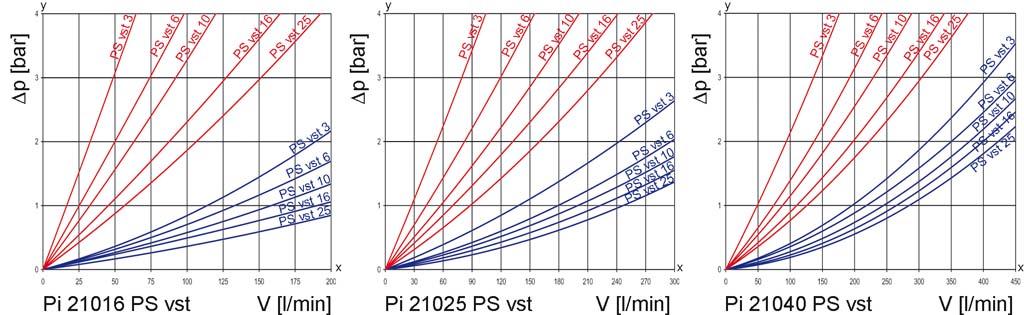
2 2. Flow rate/pressure drop curve complete filter y = differential pressure p [bar] x = flow rate V [l/min] Calculation of individual filter under Duplex Filter Pi 0 up to NG 400 2
3 3. Separation grade characteristics 4. Filter performance data tested according to ISO (multipass test) PS elements with PS vst elements with max. p 20 bar max. p bar PS 200 PS vst 6 β7(c) 3 β5(c) β7(c) PS vst PS 10 β10(c) 200 PS vst 10 β10(c) 200 PS 16 β15(c) 200 PS vst 16 β15(c) 200 PS 25 β20(c) 200 PS vst 25 β20(c) 200 PS y = betavalue x = particle size [µm] determined by multipass tests (ISO 16889) calibration according to ISO (NIST) 3 β5(c) values guaranteed up to 10 bar differential pressure values guaranteed up to 20 bar differential pressure _ 5. Quality assurance MAHLE filters and filter elements are produced according to the following international standards: Norm Designation DIN ISO 2941 Hydraulic fluid power filter elements; verification of collapse/burst resistance DIN ISO 2942 Hydraulic fluid power filter elements; verification of fabrication integrity DIN ISO 2943 Hydraulic fluid power filter elements; verification of material compatibility with fluids DIN ISO 3723 Hydraulic fluid power filter elements; metod for end load test DIN ISO 3724 Hydraulic fluid power filter elements; verification of flow fatigue characteristics ISO 3968 Hydraulic fluid power filters; evaluation of pressure drop versus flow characteristics ISO Fatigue pressure testing of metal containing envelopes in hydraulic fluid applications ISO Hydraulic fluid power filtersmultipass method for evaluation filtration performance of a filter element 6. Symbols Duplex Filter Pi 0 up to NG 400 3
4 7. Order numbers Example for ordering filter: 1. Housing design 2. 2x Filter elements V = 100 l/min and electrical maintenance indicator Type: Pi Order number: PS vst 3 NBR Type: Pi DN PS vst 3 Order number: Housing design Nominal size NG [l/min] Order number Type Pi Pi Pi Pi Pi Pi Pi Pi Pi Pi Pi Pi Pi Pi Pi Pi Pi Pi Pi Pi Pi Pi Pi Pi with bypass valve and visual indicator with bypass valve and electrical indicator with visual indicator with electrical indicator When filter with non bypass configuration is selected, the collapse pressure of the element must not be exceeded. Duplex Filter Pi 0 up to NG 400 4
5 7.2 Filter elements* Nominal size NG [l/min] Filter surface [cm²] max. p Order number Type Filter material [bar] Pi 04 DN PS 3 PS Pi DN PS 6 PS Pi DN PS 10 PS Pi DN PS 16 PS Pi DN PS 25 PS Pi DN PS vst 3 PS vst Pi DN PS vst 6 PS vst Pi DN PS vst 10 PS vst Pi DN PS vst 16 PS vst Pi DN PS vst 25 PS vst Pi 06 DN PS 3 PS Pi DN PS 6 PS Pi DN PS 10 PS Pi DN PS 16 PS Pi DN PS 25 PS Pi DN PS vst 3 PS vst Pi DN PS vst 6 PS vst Pi DN PS vst 10 PS vst Pi DN PS vst 16 PS vst Pi DN PS vst 25 PS vst Pi 10 DN PS 3 PS Pi DN PS 6 PS Pi DN PS 10 PS Pi DN PS 16 PS Pi DN PS 25 PS Pi DN PS vst 3 PS vst Pi DN PS vst 6 PS vst Pi DN PS vst 10 PS vst Pi DN PS vst 16 PS vst Pi DN PS vst 25 PS vst Pi 16 DN PS 3 PS Pi DN PS 6 PS Pi DN PS 10 PS Pi DN PS 16 PS Pi DN PS 25 PS Pi DN PS vst 3 PS vst Pi DN PS vst 6 PS vst Pi DN PS vst 10 PS vst Pi DN PS vst 16 PS vst Pi DN PS vst 25 PS vst *a wider range of elemens is available on request Duplex Filter Pi 0 up to NG 400 5
6 7.2 Filter elements* Nominal size NG [l/min] max. p Order number Type Filter material [bar] Filter surface [cm²] Pi 25 DN PS 3 PS Pi DN PS 6 PS Pi DN PS 10 PS Pi DN PS 16 PS Pi DN PS 25 PS Pi DN PS vst 3 PS vst Pi DN PS vst 6 PS vst Pi DN PS vst 10 PS vst Pi DN PS vst 16 PS vst Pi DN PS vst 25 PS vst Pi DN PS 3 PS Pi DN PS 6 PS Pi DN PS 10 PS Pi DN PS 16 PS Pi DN PS 25 PS Pi DN PS vst 3 PS vst Pi DN PS vst 6 PS vst Pi DN PS vst 10 PS vst Pi DN PS vst 16 PS vst Pi DN PS vst 25 PS vst *a wider range of elemens is available on request 8. Technical specifications Design: Nominal pressure: Pi 0410 line mounting filter 10^7 load changes 63 bar (900 psi) 10^7 load changes 25 bar (360 psi) 2x 10^6 load changes 32 bar (460 psi) Pi 1640 Test pressure: Pi 0410 Pi 1640 Temperature range: 95 bar (1370 psi) 48 bar (690 psi) 10 C to +120 C survival temperature 40 C (other temperature ranges on request) Bypass setting: Filter head material: Filter housing material: Sealing material: Maintenance indicator setting: Electrical data of maintenance indicator: Max. voltage: Max. current: Contact load: Type of protection: Contact: Cable connection: Duplex Filter Pi 0 up to NG 400 p 3.5 bar ± 10 % GAL AL/St. NBR/AL p 2.2 bar ± 10 % The switching function can be changed by turning the electric upper part by 180 (normally closed contact or normally open contact). The state on delivery is a normally closed contact. By inductivity in the direct current circuit the use of suitable protection circuit should be considered. Further maintenance indicator details and designs are available in the maintenance indicator data sheet. We draw attention to the fact that all values indicated are average values which do not always occur in specific cases of application. Our products are continually being further developed. Values, dimensions and weights can change as a result of this. Our specialized department will be pleased to offer you advice. We recommend to contact us concerning applications of our filters in areas governed by the EU Directive 94/9 EC (ATEX 95). The standard version can be used for liquids based on mineral oil (corresponding to the fluids in Goup 2 of Directive 97/23 EC Article 9). If you consider to use other fluids please contact us for additional support. Subject to technical alteration without prior notice. 250 V AC/200 V DC 1A 70 W IP 65 in inserted and secured status normally open/closed M20x1.5 6
7 9. Dimensions _ In Inlet Out Outlet *H Minimum clearance required for element change All dimensions except "J" in mm. Type øa *1 Lever locking and arresting *2 Venting screws *3 Optional wall mounting for NG 160 up to 400 B C D E F G H øi J* K L M SW Wt. [kg] Pi M8x G Pi M8x G Pi M8x G Pi M10x G1½ Pi M10x G1½ Pi M10x G1½ * SAE flange connections (3000 psi), NPT and SAE connections on request Duplex Filter Pi 0 up to NG 400 7
8 10. Installation, operating and maintenance instructions 10.1 Filter installation 10.4 Element replacement When installing filter make sure that sufficient space is available to remove filter element and filter housing. Preferably the filter should be installed with the filter housing pointing downwards. The maintenance indicator must be visible. Note: Elements may only be replaced by people who are familiar with the function of the filter. When replacing elements, appropriate safety clothing (protective goggles, gloves, safety shoes) must be worn. Note: The maintenance indicator monitors the filter side in operation, which is identified by the position of the switching lever catch. The 10.2 Connecting the electrical maintenance indicator The electrical indicator is connected via a 2pole appliance plug according to DlN EN with poles marked 1 and 2. The electrical section can be inverted to change from normally open to normally closed position or vice versa. The state on delivery is a normally closed contact When should the filter element be replaced? 1. Filters equipped with visual and electrical maintenance indicator: changeover transfer valve must be switched prior filter servicing. Now the signal of the maintenance indicators cancelled and the red button can be repressed again: 2. During cold starts, the indicator may give a warning signal. Press the red button of the visual indicator once again only after operating temperature has been reached. If the red button immediately pops up again and/or the electrical signal has not switched off after reaching operating temperature the filter element must be replaced after the end of the shift. Please always ensure that you have original MAHLE spare elements in stock: Disposable elements cannot be cleaned Duplex Filter Pi 0 up to NG 400 Operate and hold pressure equalizing lever located behind switching lever. Pull catch knob and swivel switching lever. Engage the catch on the clear filter side. Place through or drip pan underneath to collect leaving oil. Loosen vent screw of the filter side not in use by 23 turns; max. until contact is made with the safety stop. Unscrew filter housing by rotating same counterclockwise and clean with a suitable medium. Warning: The shift lever may not, from now until the screwing back in of the filter housing (7.), be activated under any circumstances! Remove filter element with a sidetoside motion. Check Oring on the filter house for damage. Replace, if necessary. Make sure that the order number on the spare element corresponds to the oder number of the filter nameplate. Lightly lubricate the threads of the filter housing and screw into the filter head. Maximum tightening torque for NG 40 to 100 = 60 Nm, for NG 160 to 400 = 100 Nm. To refill the filter chamber, operate only the pressure equalizing lever (leave the switching lever arrested in its catch) long enough for the medium to emerge bubble free from the vent bore. Tighten vent screw. Check filter for leaks by operating the pressure equalizing lever once again. 8
9 11. Spare parts list Order number for spare parts Position Type Order number Seal kit for housing Pi 04 Pi 10 bis NBR FPM EPDM Pi 16 Pi 40 NBR FPM EPDM Seal kit for maintenance indicator bis NBR FPM EPDM Maintenance indicator Duplex Filter Pi 0 up to NG 400 Visual PiS 3098/ Electrical PiS 3097/ Electrical upper section only
10 MAHLE Industriefiltration GmbH Schleifbachweg 45 D74613 Öhringen Phone Fax /2012 Duplex Filter Pi 0 up to NG

11 Duplex Filter Pi Nominal pressure 32/63 bar (460/900 psi), nominal size up to Features.High performance filters for modern hydraulic systems Modular system Compact design Minimal pressure drop through optimal flow design Visual/electrical/electronic maintenance indicator Threaded connections Change over valve on upstream side Ergonomic switchover handle with safety lock and pressure compensation._ Useroptimized onehandoperation Equipped with highly efficient glass fibre PS filter elements Beta rated elements according to ISO multipass test Elements with high differential pressure stability and dirt holding capacity Other connections on request Worldwide distribution
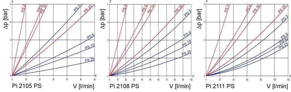
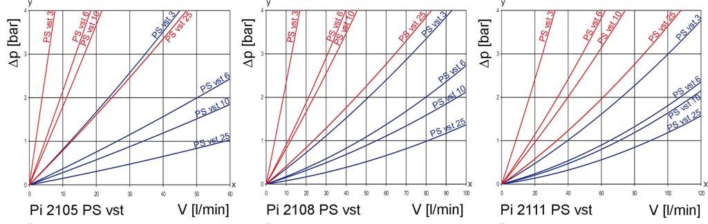
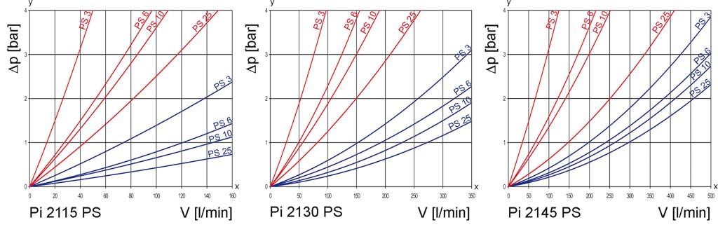
12 2. Flow rate/pressure drop curve complete filter Duplex Filter Pi up to NG 600 2
13 y = differential pressure p [bar] x = flow rate V [l/min] Calculation of individual filter under 3. Separation grade characteristics 4. Filter performance data tested according to ISO (multipass test) PS elements with PS vst elements with max. p 20 bar max. p bar β5(c) 200 PS vst 3 β5(c) β7(c) 200 PS vst 6 β7(c) 200 PS 10 β10(c) 200 PS vst 10 β10(c) 200 PS 25 β20(c) 200 PS vst 25 β20(c) 200 PS 3 PS values guaranteed up to 10 bar differential pressure values guaranteed up to 20 bar differential pressure y = betavalue x = particle size [µm] determined by multipass tests (ISO 16889) calibration according to (NIST) 5. Quality assurance MAHLE filters and filter elements are produced according to the following international standards: Norm Designation DIN ISO 2941 Hydraulic fluid power filter elements; verification of collapse/burst resistance DIN ISO 2942 Hydraulic fluid power filter elements; verification of fabrication integrity DIN ISO 2943 Hydraulic fluid power filter elements; verification of material compatibility with fluids DIN ISO 3723 Hydraulic fluid power filter elements; method for end load test DIN ISO 3724 Hydraulic fluid power filter elements; verification of flow fatigue characteristics ISO 3968 Hydraulic fluid powerfiltersevaluation of pressure drop versus flow characteristics ISO Fatigue pressure testing of metal containing envelopes in hydraulic fluid applications ISO Hydraulic fluid power filtersmultipass method for evaluation filtration performance of a filter element Duplex Filter Pi up to NG 600 3
14 6. Symbols 7. Order numbers Example for ordering filters: 1. Housing design 2. Filter element V = 80 l/min and visual/electrical indicator Type: Pi 8069 Order number: PS vst 3 Type: Pi 2208 PS vst 3 Order number: Housing design Nominal size NG [l/min] Order number Type Pi Pi Pi Pi Pi Pi Pi Pi Pi Pi Pi Pi Pi Pi Pi Pi Pi Pi Pi Pi Pi Pi Pi Pi Pi Pi Pi Pi with bypass valve and visual indicator with bypass valve and electrical indicator with visual indicator with electrical indicator When filter with non bypass configuration is selected, the collapse pressure of the element must not be exceeded. Duplex Filter Pi up to NG 600 4
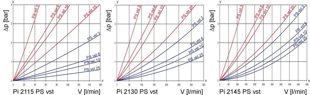
15 7.2 Filter elements* Nominal size NG [l/min] max. p Order number Type Filter material Filter surface [cm²] [bar] Pi 5 PS 3 PS Pi 5105 PS 6 PS Pi 3105 PS 10 PS Pi 4105 PS 25 PS Pi 2205 PS vst 3 PS vst Pi 5205 PS vst 6 PS vst Pi 3205 PS vst 10 PS vst Pi 4205 PS vst 25 PS vst Pi 8 PS 3 PS Pi 5108 PS 6 PS Pi 3108 PS 10 PS Pi 4108 PS 25 PS Pi 2208 PS vst 3 PS vst Pi 5208 PS vst 6 PS vst Pi 3208 PS vst 10 PS vst Pi 4208 PS vst 25 PS vst Pi 2111 PS 3 PS Pi 5111 PS 6 PS Pi 3111 PS 10 PS Pi 4111 PS 25 PS Pi 2211 PS vst 3 PS vst Pi 5211 PS vst 6 PS vst Pi 3211 PS vst 10 PS vst Pi 4211 PS vst 25 PS vst Pi 2115 PS 3 PS Pi 5115 PS 6 PS Pi 3115 PS 10 PS Pi 4115 PS 25 PS Pi 2215 PS vst 3 PS vst Pi 5215 PS vst 6 PS vst Pi 3215 PS vst 10 PS vst Pi 4215 PS vst 25 PS vst Pi 2130 PS 3 PS Pi 5130 PS 6 PS Pi 3130 PS 10 PS Pi 4130 PS 25 PS Pi 2230 PS vst 3 PS vst Pi 5230 PS vst 6 PS vst Pi 3230 PS vst 10 PS vst Pi 4230 PS vst 25 PS vst Pi 2145 PS 3 PS Pi 5145 PS 6 PS Pi 3145 PS 10 PS Pi 4145 PS 25 PS Pi 2245 PS vst 3 PS vst Pi 5245 PS vst 6 PS vst Pi 3245 PS vst 10 PS vst Pi 4245 PS vst 25 PS vst *a wider range of element types is availble on request Duplex Filter Pi up to NG 600 5
16 7.2 Filter elements* Nominal size NG [l/min] 600 max. p Order number Type Filter material Pi 2160 PS 3 PS Pi 5160 PS 6 PS Pi 3160 PS 10 PS Pi 4160 PS 25 PS 25 [bar] Filter surface [cm²] *a wider range of element types is availble on request 8. Technical specifications Design: Nominal pressure: Pi 5 Pi 2111 line mounting filter 10^7 load changes 63 bar (900 psi) 10^7 load changes 25 bar (360 psi) 2x 10^6 load changes 32 bar (460 psi) Pi 2115 Pi 2160 Test pressure: Pi 5 Pi 2111 Pi 2115 Pi 2160 Temperature range: 95 bar (1370 psi) 48 bar (690 psi) 10 C to +120 C survival temperature 40 C (other temperature ranges on request) Bypass setting: Filter head material: Filter housing material: Sealing material: Maintenance indicator setting: Electrical data of maintenance indicator: Max. voltage: Max. current: Contact load: Type of protection: Contact: Cable connection: Duplex Filter Pi up to NG 600 p 3.5 bar ± 10 GAL AL/St NBR/AL p 2.2 bar ± 10 % The switching function can be changed by turning the electric upper part by 180 (normally closed contact or normally open contact). The state on delivery is a normally closed contact. By inductivity in the direct current circuit the use of suitable protection circuit should be considered. Further maintenance indicator details and designs are available in the maintenance indicator data sheet. We draw attention to the fact that all values indicated are average values which do not always occur in specific cases of application. Our products are continually being further developed. Values, dimensions and weights can change as a result of this. Our specialized department will be pleased to offer you advice. We recommend to contact us concerning applications of our filters in areas governed by the EU Directive 94/9 EC (ATEX 95). The standard version can be used for liquids based on mineral oil (corresponding to the fluids in Goup 2 of Directive 97/23 EC Article 9). If you consider to use other fluids please contact us for additional support. Subject to technical alteration without prior notice. 250 V AC/200 V DC 1A 70 W IP 65 in inserted and secured status normally open/closed M20x1.5 6
17 9. Dimensions In Inlet Out Outlet *H Minimum clearance required for element change *1 *2 *3 *4 Lever locking and arresting Venting screws Optional fixing for NG 150 to 600 Housing version NG 600 All dimensions except "J" in mm Type øa B C D E F G H øi J* K L M SW Wt. [kg] Pi M8x G Pi M8x G Pi M8x G Pi M10x G1½ Pi M10x G1½ Pi M10x G1½ Pi M10x G1½ * SAE flange connections (3000 psi), NPT and SAE connections on request Duplex Filter Pi up to NG 600 7
18 10. Installation, operating and maintenance instructions 10.1 Filter installation When installing the filter make sure that sufficient space is available 10.4 Element replacement Note: Elements may only be replaced by people who are familiar to remove filter element and filter housing. Preferably the filter should be installed with the filter housing pointing downwards. The maintenance indicator must be visible Connecting the electrical maintenance indicator The electrical indicator is connected via a 2pole appliance plug ac with the function of the filter. When replacing elements, appropriate safety clothing (protective goggles, gloves, safety shoes) must be worn. Note: The maintenance indicator monitors the filter side in operation, which is identified by the position of the switching lever catch. The changeover transfer valve must be switched prior filter servicing. cording to DlN EN with poles marked 1 and 2. The electrical section can be inverted to change from normally open position to normally closed position or vice versa. The state on delivery is a normally closed contact When should the filter element be replaced? 1. Filters equipped with visual and electrical maintenance indicator: During cold starts, the indicator may give a warning signal. Now the signal of the maintenance indicators cancelled and the red button can be repressed again. 1. Operate and hold pressure equalizing lever located behind switching lever. Pull catch knob and swivel switching lever. Engage the catch on the clear filter side. Place through or drip pan underneath to collect leaving oil. 2. Loosen vent screw of the filter side not in use by 23 turns; max. until contact is made with the safety stop. 3. Unscrew filter housing by rotating same counterclockwise and clean with a suitable medium. Press the red button of the visual indicator once again only after operating temperature has been reached. lf the red button immediately pops up again and/or the electrical signal has not switched off after reaching operating temperature, the filter element must be replaced after the end of the shift. Please always ensure that you have original MAHLE spare elements in stock: Disposable elements cannot be cleaned. Warning: The shift lever may not, from now until the screwing back in of the filter housing (7.), be activated under any circumstances! Remove filter element with a sidetoside motion. Check Oring on the filter house for damage. Replace, if necessary. Make sure that the order number on the spare element corresponds to the oder number of the filter nameplate. Lightly lubricate the threads of the filter housing and screw into the filter head. Maximum tightening torque for NG 50 to 110 = 60 Nm, for NG 150 to 600 = 100 Nm. To refill the filter chamber, operate only the pressure equalizing lever (leave the switching lever arrested in its catch) long enough for the medium to emerge bubble free from the vent bore. Tighten vent screw. Check filter for leaks by operating the pressure equalizing lever once again Duplex Filter Pi up to NG 600 8
19 11. Spare parts list Order number for spare parts Position Type Order number Seal kit for housing Pi 5 Pi 2111 NBR FPM EPDM Pi 2115 Pi 2160 NBR FPM EPDM Seal kit for maintenance indicator NBR FPM EPDM Maintenance indicator Duplex Filter Pi up to NG 600 Visual PiS 3098/ Electrical PiS 3097/ Electrical upper section only
20 MAHLE Industriefiltration GmbH Schleifbachweg 45 D74613 Öhringen Phone Fax /2013 Duplex Filter Pi up to NG

21 Duplex Filter Pi 2110 Nominal pressure 40 bar (570 psi), nominal size 630 and 1000 according DIN Features High performance filters for modern hydraulic systems Modular system Compact design Minimal pressure drop through optimal flow design Visual/electrical/electronic maintenance indicator Flanged connections _ Quality filters, easy to service Equipped with highly efficient glass fibre Smx filter elements Beta rated elements according to ISO multipass test Elements with high differential pressure stability and dirt holding capacity Worldwide distribution

![pressure p [bar] x = flow rate V](/docs-images/76/73040203/images/22-1.jpg "[l/min] Duplex Filter Pi 2110 NG")
22 2. Flow rate/pressure drop curve complete filter y = differential pressure p [bar] x = flow rate V [l/min] Duplex Filter Pi 2110 NG
23 3. Separation grade characteristics 4. Filter performance data tested according to ISO (multipass test) Smx elements with Smx vst elements with max. p 20 bar max. p bar Smx 200 Smx vst 6 β7(c) 3 β5(c) β7(c) Smx vst Smx 10 β10(c) 200 Smx vst 10 β10(c) 200 Smx 16 β15(c) 200 Smx vst 16 β15(c) 200 Smx 25 β20(c) 200 Smx vst 25 β20(c) 200 Smx y = betavalue x = partcle size [µm] determined by multipass tests (ISO 16889) calibration according to ISO (NIST) 3 β5(c) values guaranteed up to 10 bar differential pressure values guaranteed up to 20 bar differential pressure. 5. Quality assurance MAHLE filters and filter elements are produced according to the following international standards: Norm Designation DIN ISO 2941 Hydraulic fluid power filter elements; verification of collapse/burst resistance DIN ISO 2942 Hydraulic fluid power filter elements, verification of fabrication integrity DIN ISO 2943 Hydraulic fluid power filter elements, verification of material compatibility with fluids DIN ISO 3723 Hydraulic fluid power filter elements, methods for end load test DIN ISO 3724 Hydraulic fluid power filter elements, verification of flow fatigue charactersitics ISO 3968 Hydraulic fluid power filters; evaluation of pressure drop versus flow characteristics ISO Fatigue pressure testing of metal containing envelopes in hydraulic fluid applications ISO Hydraulic fluid power filters; multipass method for evaluation filtration performance of a filter element 6. Symbols Duplex Filter Pi 2110 NG
24 7. Order numbers Example for ordering filters: 1. Housing design 2. 2 x Filter element V = 630 l/min and visual/electrical maintenance indicator Type: Pi Order number: Smx vst 25 Type: Pi DN Smx vst 25 Order number: Housing design Nominal size NG [l/min] Order number with bypass valve and visual indicator Type Pi Pi Pi Pi Pi Pi Pi Pi with bypass valve and electrical indicator with visual indicator with electrical indicator When filter with non bypass configuration is selected the collapse pressure must not be exceeded! 7.2 Filter elements* Nominal size NG [l/min] Order number max. p Type Filter material [bar] Filter surface [cm²] Pi 63 DN Smx 3 Smx Pi DN Smx 6 Smx Pi DN Smx 10 Smx Pi DN Smx 16 Smx Pi DN Smx 25 Smx Pi DN Smx vst 3 Smx vst Pi DN Smx vst 6 Smx vst Pi DN Smx vst 10 Smx vst Pi DN Smx vst 16 Smx vst Pi DN Smx vst 25 Smx vst Pi DN Smx 3 Smx Pi 20 DN Smx 6 Smx Pi DN Smx 10 Smx Pi DN Smx 16 Smx Pi DN Smx 25 Smx Pi DN Smx vst 3 Smx vst Pi 70 DN Smx vst 6 Smx vst Pi DN Smx vst 10 Smx vst Pi DN Smx vst 16 Smx vst Pi DN Smx vst 25 Smx vst * A wider range of element types is available on request. Duplex Filter Pi 2110 NG
 p 3.")
25 8. Technical specifications Design: Nominal pressure: Test pressure: Temperature range: line mounting filter 40 bar (570 psi) 60 bar (850 psi) 10 C to +120 C (other temperature ranges on request) Minimum viscosity of the fluid: 10 mm²/s (if viscosity of the fluid < 10 mm²/s on request) p 3.5 bar ± 10 % Bypass setting: Filter head material: Filter housing material: Filter cover material: Sealing material: Maintenance indicator setting: GGG St GGG NBR p 2.2 bar ± 0.3 bar Electrical data of maintenance indicator: Max. voltage: Max. current: Contact load: Type of protection: 250 V AC/200 V DC 1A 70 W IP 65 in inserted and Contact: Cable sleave: secured status normally open/closed M20x1.5 The switching function can be changed by turning the electric upper part by 180 (normally closed contact or normally open contact). The state on delivery is a normally closed contact. By inductivity in the direct current circuit the use of suitable protection circuit should be considered. Further maintenance indicator details and designs are available in the maintenance indicator data sheet. _ We draw attention to the fact that all values indicated are average values which do not always occur in specific cases of application. Our products are continually being further developed. Values, dimensions and weights can change as a result of this. Our specialized department will be pleased to offer you advice. We recommend you to contact us concerning applications of our filters in areas governed by the EU Directive 94/9 EC (ATEX 95). The standard version can be used for liquids based on mineral oil (corresponding to the fluids in Group 2 of Directive 97/23 EC Article 9). If you consider to use other fluids please contact us for additional support. Subject to technical alteration without prior notice. In = Inlet Out = Outlet *1 Clearance B *2 Pressure equalization valve *3 Drain screw G¼ *4 Maintenance indicator *5 Vent screw. 9. Dimensions All dimensions in mm. Type Connection A B Pi DN Pi DN Duplex Filter Pi 2110 NG Weight [kg] 5
26 10. Installation, operating and maintenance instructions 10.1 Filter installation When installing the filter make sure that sufficient space is available 8. Push the element carefully over the spigot and tight cover until full stop. Back off the cover 1/8 turn. to remove filter element and filter housing. The maintenance indicator must be visible Connecting the electrical maintenance indicator The electrical indicator is connected via a 2pole appliance plug according to DlN EN with poles marked 1 and 2. The elec 9. Tighten drain plug housing bottom. 10. To refill the filter chamber, operate only the pressure equalizing lever, until fluid emerges bubblefree from the drain cavity. 11. Tight vent screw. Check for leckage by actuating the equalizing lever again. trical section can be inverted to change from normally open to normally closed position or vice versa When should the filter element be replaced? 1. Filters equipped with visual and electrical maintenance indicator: During cold starts, the indicator may give a warning signal. Press the red button of the visual indicator once again only after operating temperature has been reached. If the red button immediately pops up again and/or the electrical signal has not switched off after reaching operating temperature the filter element must be replaced after the end of the shift. Filters without maintenance indicator: The filter element should be replaced after the trial run or flushing of the system. Afterwards follow instructions of the manufacturer. Please always ensure that you have original MAHLE spare elements in stock: disposable elements (Smx) cannot be cleaned Element replacement Note: The maintenance indicator monitors the filter side in operation, which is identified by the position of the switching lever catch. The changeover transfer valve must be switched prior filter servicing. Now the signal of the maintenance indicators cancelled and the red button can be repressed again. 1. Operate and hold pressure equalizing lever located behind switching lever. Pull catch knob and swivel switching lever. Place through or drip pan underneath to collect leaving oil. Close pressure equalization valve. 2. Loosen vent screw of the filter side not in use by 23 turns; max. until contact is made with the safety stop. 3. Remove drain plug in housing bottom and drain oil. 4. Unscrew filter cover counterclockwise. 5. Lift out filter element. 6. Check seal on filter cover. We recommend replacement in any case. 7. Make sure that the order number on the spare element corresponds to the order number of the filter nameplate. To ensure no contamination occurs during the exchange of the element first open the plastic bag and push the element over the spigot in the filter head. Now remove plastic bag. 11. Spare parts list Order numbers for spare parts Position Type Order number Seal kit for housing NBR FPM EPDM Maintenance indicator Visual PiS 3098/2, Visual/electrical PiS 3097/2, Electrical upper section only Seal kit for maintenance indicator NBR FPM EPDM MAHLE Industriefiltration GmbH, Schleifbachweg 45, D74613 Öhringen, Phone , Fax , industrialfiltration@mahle.com, /2012 Duplex Filter Pi 2110 NG

27 Duplex Filter Pi 232 Nominal pressure 25 bar (360 psi), nominal size 800 and 1400 according DIN Features Duplex filter for gear boxes, lubrication and hydraulic systems Modular system Compact design Weight optimized design Minimal pressure drop through optimal flow design Flange connections, DIN DN 80, SAE 3 Visual/electrical maintenance indicator Drain on dirt and clean side Beta rated elements according to ISO multipass test Defined cleanliness classes according to ISO 4406/1999 Elements with high differential pressure stability and dirt holding capacity Quality filters, easy to service Worldwide sales and service
![2. Flow rate/pressure drop curve complete filter y = differential pressure p [bar] x = flow rate V [l/min] 3. Separation grade characteristics 4.](/docs-images/76/73040203/images/28-0.jpg "Filter performance data tested according to ISO 16889 (multipass test) PS elements with max.")
28 2. Flow rate/pressure drop curve complete filter y = differential pressure p [bar] x = flow rate V [l/min] 3. Separation grade characteristics 4. Filter performance data tested according to ISO (multipass test) PS elements with max. p 20 bar PS 3 β5(c) 200 PS 6 β7(c) 200 PS 10 β10(c) 200 PS 25 β20(c) 200 values guaranteed up to 10 bar differential pressure y = betavalue x = partcle size [µm] determined by multipass tests (ISO 16889) calibration according to ISO (NIST) 5. Quality assurance MAHLE filters and filter elements are produced according to the following international standards: Norm DIN ISO 2941 DIN ISO 2942 DIN ISO 2943 DIN ISO 3723 DIN ISO 3724 ISO 3968 ISO ISO Designation Hydraulic fluid power filter elements; verification of collapse/burst resistance Hydraulic fluid power filter elements, verification of fabrication integrity Hydraulic fluid power filter elements, verification of material compatibility with fluids Hydraulic fluid power filter elements, methods for end load test Hydraulic fluid power filter elements, verification of flow fatigue charactersitics Hydraulic fluid power filters; evaluation of pressure drop versus flow characteristics Fatigue pressure testing of metal containing envelopes in hydraulic fluid applications Hydraulic fluid power filters; multipass method for evaluation filtration performance of a filter element Duplex Filter Pi 232 NG
29 6. Symbols 7. Order numbers Example for ordering filters: 1. Housing design 2. 2x Filter element V = 800 l/min and visual/electrical maintenance indicator Type: Pi Order number: Housing design PS 25 Type: PS 25 Order number: Nominal size NG [l/min] Order number Type with bypass valve and visual indicator with bypass valve and electrical indicator Pi Pi Pi Pi Pi Pi Pi Pi When filter with non bypass configuration is selected the collapse pressure must not be exceeded! 7.2 Filter elements for standard housing design* with visual indicator with electrical indicator Nominal size NG [l/min] Order number Type Filter material max. p [bar] Filter surface [cm²] SmN 2 SmN PS 3 PS PS 6 PS PS 10 PS PS 25 PS SmN 2 SmN PS 3 PS PS 6 PS PS 10 PS PS 25 PS *other element types are available on request Duplex Filter Pi 232 NG
30 8. Technical specifications Design: line mounting filter Nominal pressure: 10^7 load changes 25 bar (360 psi) Test pressure: 33 bar (470 psi) Temperature range: 10 C to +120 C survival temperature 40 C (other temperature ranges on request) minimum viscosity of the fluid: 10 mm²/s Bypass setting: p 3.5 bar ± 10 Filter head material: GAL Filter housing material: AL Filter cover material: GAL Sealing material: NBR Maintenance indicator setting p 2.2 bar ± 10 % Electrical data of maintenance indicator: Max. voltage: 250 V AC/200 V DC Max. current: 1 A Contact load: 70 W Type of protection: IP 65 in inserted and secured status Contact: normally open/closed Cable sleave: M20x Dimensions The switching function can be changed by turning the electric upper part by 180 (normally closed contact or normally open contact). The state on delivery is a normally closed contact. By inductivity in the direct current circuit the use of suitable protection circuit should be considered. Further maintenance indicator details and designs are available in the maintenance indicator data sheet. We draw attention to the fact that all values indicated are average values which do not always occur in specific cases of application. Our products are continually being further developed. Values, dimensions and weights can change as a result of this. Our specialized department will be pleased to offer you advice. We recommend you to contact us concerning applications of our filters in areas governed by the EU Directive 94/9 EC (ATEX 95). The standard version can be used for liquids based on mineral oil (corresponding to the fluids in Group 2 of Directive 97/23 EC Article 9). If you consider to use other fluids please contact us for additional support. Subject to technical alteration without prior notice. In Inlet *3 Drain dirt side G½ Out Outlet *4 Maintenance indicator *1 Pressure equalization screw *5 Clearance B *2 Drain clean side G½ Duplex Filter Pi 232 NG
31 All dimensions in mm. Type Connection A B Weight [kg] Pi DN Pi DN Installation, operating and maintenance instructions 10.1 Filter installation When installing the filter make sure that sufficient space is available to remove filter element and filter housing. The maintenance indicator must be visible Connecting the electrical maintenance indicator The electrical indicator is connected via a 2pole appliance plug according to DlN EN with poles marked 1 and 2. The electrical section can be inverted to change from normally open to normally closed position or vice versa. The state on delivery is a normally closed contact When should the filter element be replaced? 1. Filters equipped with visual and electrical maintenance indicator: During cold starts, the indicator may give a warning signal. Press the red button of the visual indicator once again only after operating temperature has been reached. If the red button immediately pops up again and/or the electrical signal has not switched off after reaching operating temperature the filter element must be replaced after the end of the shift. 2. Filters without maintenance indicator: The filter element should be replaced after the trial run or flushing of the system. Afterwards follow instructions of the manufacturer. 3. Please always ensure that you have original MAHLE spare elements in stock: disposable elements (PS, SmN) cannot be cleaned Element replacement Note: Elements may only be replaced by people who are familiar with the function of the filter. When replacing elements, appropriate safety clothing (protective goggles, gloves, safety shoes) must be worn. Note: The maintenance indicator monitors the filter side in operation, which is identified by the position of the switching lever catch. The changeover transfer valve must be switched prior filter servicing. Now the signal of the maintenance indicators cancelled and the red button can be repressed again. 1. Operate pressure equalizing screw. Swivel switching lever. Place through or drip pan underneath to collect leaving oil. Close pressure equalization screw. 2. Loosen vent screw of the filter side not in use by 23 turns. 3. Remove drain plug in housing bottom and drain oil. 4. Unscrew filter cover counterclockwise. Warning: The shift lever may not, from now until the screwing back in of the filter housing (7.), be activated under any circumstances! 5. Lift out filter element. 6. Check seal on filter cover. We recommend replacement in any case. 7. Make sure that the order number on the spare element corresponds to the order number of the filter nameplate. Remove the element packaging and put the element with the oring side down into the housing. 8. Push the element carefully over the spigot and tight cover with the handtight. 9. Tighten drain plug housing bottom. 10. To refill the filter chamber, operate only the pressure equalizing screw. Tighten the screw when fluid emerges bubblefree from the drain. 11. Tight vent screw. Check for leckage by actuating the equalizing screw again. Duplex Filter Pi 232 NG
32 11. Spare parts list Order numbers for spare parts Position Type Order number Seal kit for housing NBR FPM EPDM Maintenance indicator Visual PiS 3098/2, Visual/electrical PiS 3097/2, Electrical upper section only Seal kit for maintenance indicator NBR FPM EPDM MAHLE Industriefiltration GmbH Schleifbachweg 45 D74613 Öhringen Phone Fax /2012 Duplex Filter Pi 232 NG

33 Duplex Filter Pi 241 Nominal pressure 40 bar (570 psi), nominal size 50 up to Features. High performance filters for modern hydraulic, lubrication and fuel systems Modular system Compact design Minimal pressure drop through optimal flow design Ball switching unit Visual/electrical/electronic maintenance indicator Flanged and threaded connections Variable operating and mounting possibilities Extensive range of accessories Quality filters, easy to service Equipped with highly efficient glass fibre PS filter elements Beta rated elements according to ISO multipass test Elements with high differential pressure stability and dirt holding capacity Worldwide distribution
34 2. Flow rate/pressure drop curve complete filter. y = differential pressure p [bar] x = flow rate V [l/min] 1 = PS 3 3 = PS 10 5 = PS 25 7 = Drg 25 9 = Drg 60 2 = PS 6 4 = PS 16 6 = Drg 10 8 = Drg = Drg 100 Duplex Filter Pi 241 NG 50 up to 80 2
35 3. Separation grade characteristics 4. Filter performance data tested according to ISO (multipass test) PS elements with max. p 20 bar _ PS 3 β 5(C) 200 PS 6 β 7(C) 200 PS 10 β 10(C) 200 PS 16 β 16(C) 200 PS 25 β 20(C) 200 values guaranteed up to 10 bar differential pressure y = betavalue x = particle size [µm] determined by multipass tests (ISO 16889) calibration according to ISO (NIST) _ 5. Quality assurance MAHLE filters and filter elements are produced according to the following international standards: Norm DIN ISO 2941 DIN ISO 2942 DIN ISO 2943 DIN ISO 3723 DIN ISO 3724 ISO 3968 ISO ISO Designation Hydraulic fluid power filter elements; verification of collapse/burst resistance Hydraulic fluid power filter elements; verification of fabrication integrity Hydraulic fluid power filter elements; verification of material compatibility with fluids Hydraulic fluid power filter elements; method for end load test Hydraulic fluid power filter elements; verification of flow fatigue characteristics Hydraulic fluid power filters; evaluation of pressure drop versus flow characteristics Fatigue pressure testing of metal containing envelopes in hydraulic fluid applications Hydraulic fluid power filters; multipass method for evaluation filtration performance of a filter element 6. Symbols Duplex Filter Pi 241 NG 50 up to 80 3
36 7. Type number key and order numbers 7.1 Type number key housings Type 241 Duplex filter Nominal size [l/min] 005 NG NG 80 Connection 1 SAE flange 4 Thread connection Clearance opening C 1" DN 25 Seal material N NBR F FPM E EPDM Housing code* 046 with screw plug 057 with bypass and visual indicator 058 with bypass and electrical indicator 068 with visual indicator 069 with electrical indicator Special equipment M Magnet Pi / 1 C/ N 069/ M Example for ordering *Other types on request Example for ordering filters: 1. Filter housing 2. Filter element V = 80 l/min, connection 1" SAE, seal NBR und visual/electrical maintenance indicator Type: Pi /1C/N069 Order number: PS 10 Type: Pi AN PS 10 Order number: Order numbers housings Nominal size NG [l/min] Order number Type with blank plug for indicator with bypass valve and visual indicator with bypass valve and electrical indicator with visual indicator Pi /1C/N Pi /1C/N Pi /1C/N Pi /1C/N Pi /1C/N Pi /1C/N Pi /1C/N Pi /1C/N Pi /1C/N Pi /1C/N069 When filter with non bypass configuration is selected, the collapse pressure of the element must not be exceeded. with electrical indicator Duplex Filter Pi 241 NG 50 up to 80 4
37 7.3 Filter elements (a wider range of element types is availble on request) Nominal size max. p Filter surface NG [l/min] Order number Type Filter material [bar] [cm²] Pi 05 AN PS 3 PS Pi AN PS 6 PS Pi AN PS 10 PS Pi AN PS 16 PS Pi AN PS 25 PS Pi AN Mic 10 Mic Pi AN Mic 25 Mic Pi AN Drg 10 Drg Pi AN Drg 25 Drg Pi AN Drg 40 Drg Pi AN Drg 60 Drg Pi AN Drg 100 Drg Pi 08 AN PS 3 PS Pi AN PS 6 PS Pi AN PS 10 PS Pi AN PS 16 PS Pi AN PS 25 PS Pi AN Mic 10 Mic Pi AN Mic 25 Mic Pi AN Drg 10 Drg Pi AN Drg 25 Drg Pi AN Drg 40 Drg Pi AN Drg 60 Drg Pi AN Drg 100 Drg Technical specifications Design: Duplex filter Nominal pressure: 40 bar (570 psi) Test pressure: 60 bar (860 psi) Temperature range: 10 C to +120 C (other temperature ranges on request) Bypass setting: p 3.5 bar ± 10 % Filter housing material: ENGJS400 Switch parts material: Stainless steel Sealing material: NBR/AL Maintenance indicator setting: p 2.2 bar ± 10 % Electrical data of maintenance indicator: Maximum voltage: 250 V AC/200 V DC Maximum current: 1 A Contact load: 70 W Type of protection: IP 65 in inserted and secured status Contact: normally open/closed Cable sleave: M20x1.5 The switching function can be changed by turning the electric upper part by 180 (normally closed contact or normally open contact). The state on delivery is a normally closed contact. By inductivity in the direct current circuit the use of suitable protection circuit should be considered. Further maintenance indicator details and designs are available in the maintenance indicator data sheet. We draw attention to the fact that all values indicated are average values which do not always occur in specific cases of application. Our products are continually being further developed. Values, dimensions and weights can change as a result of this. Our specialized department will be pleased to offer you advice. We recommend you to contact us concerning applications of our filters in areas governed by the EU Directive 94/9 EC (ATEX 95). The standard version can be used for liquids based on mineral oil (corresponding to the fluids in Group 2 of Directive 97/23 EC Article 9). If you consider to use other fluids please contact us for additional support. Subject to technical alteration without prior notice. Duplex Filter Pi 241 NG 50 up to 80 5
38 9. Dimensions All dimensions in mm. Type Connections* H B Weight in [kg] SAE DN 25/G1" SAE DN 25/G1" * Other connections on request In Inlet *3 Drain outlet clean side G¼ Out Outlet *4 Type plate *1 Venting G¼ *5 Maintenance indicator optional *2 Drain outlet dirt side G¼ *6 Clearance B Duplex Filter Pi 241 NG 50 up to 80 6
39 10. Installation, operating and maintenance instructions 10.1 Filter installation When installing the filter make sure that sufficient space is available to remove filter element and filter housing. The maintenance indicator must be visible Connecting the electrical maintenance indicator The electrical indicator is connected via a 2pole appliance plug according to DlN EN with poles marked 1 and 2. The electrical section can be inverted to change from normally open position to normally closed position or vice versa. The state on delivery is a normally closed contact When should the filter element be replaced? 1. Filters equipped with visual and electrical maintenance indicator: During cold starts, the indicator may give a warning signal. Press the red button of the visual indicator once again only after operating temperature has been reached. lf the red button immediately pops up again and/or the electrical signal has not switched off after reaching operating temperature, the filter element must be replaced. 2. Filters without maintenance indicator: The filter element should be replaced after the trial run or flushing of the system. Afterwards follow instructions of the manufacturer. 3. Please always ensure that you have original MAHLE spare elements in stock: Disposable elements (PS/Mic) cannot be cleaned Element replacement Note: Elements may only be replaced by people who are familiar with the function of the filter. When replacing elements, appropriate safety clothing (protective goggles, gloves, safety shoes) must be worn. Note: The maintenance indicator monitors the filter side in operation. This is indicated by notches (N) on the switching shaft. Before carrying out filter maintenance, switch off the housing to be serviced. 1. Move switching lever (S) completely to the stop. 2. Loosen vent plug (V) on the filter side now shut down by 23 turns. 3. Remove drain plug "1" (D1) and allow the medium to drain. 4. Remove drain plug "2" (D2) and allow the medium to drain. 5. Unscrew filter cover (L) by turning in anticlockwise direction. Warning: The shift lever may not, from now until the screwing back in of the filter housing, be activated under any circumstances! 6. Lift out filter element (E) from above. 7. Check seal (2) on filter cover.we recommend replacement in any case. 8. Make sure that the order number on the spare element corresponds to the order number of the filter name plate (T). Remove the element packaging and insert the element into the housing with the closed side facing upwards. 9. Push the element carefully into the holding fixture and tighten cover against stop. 10. Screw in drain plugs "1" and "2" and tighten (3035 Nm). 11. When filling the filter chamber, move the switching lever to the middle position until the medium flows out of the vent bore bubblefree. Tighten vent plug (3035 Nm). 12. Check the serviced filter chamber for leaks. 13. Move the switching lever back to stop position and put the serviced filter chamber out of operation again. Duplex Filter Pi 241 NG 50 up to 80 7
40 11. Spare parts list Order number for spare parts Position Type Order number Seal kit for housing Pi Pi NBR FPM EPDM Seal kit for maintenance indicator NBR FPM EPDM Maintenance indicator Visual PiS 3098/ Electrical PiS 3097/ Electrical upper section only Oil drip pan Pi Pi SAE welding counterflange 3000 psi incl. ORing and mounting screws SAE 1" NBR Drain plugs with permanent magnet G¼" MAHLE Industriefiltration GmbH Schleifbachweg Öhringen Phone Fax /2012 Duplex Filter Pi 241 NG 50 up to 80 8

41 Duplex Filter Pi 281 Nominal pressure 10/16 bar (140/230 psi), nominal size 1250 up to Features _ High performance filters for modern hydraulic systems Modular system Compact design Minimal pressure drop through optimal flow design Visual/electrical/electronic maintenance indicator Flanged connections _ : Quality filters, easy to service Equipped with highly efficient glass fibre PS filter elements Beta rated elements according to ISO multipass test Elements with high differential pressure stability and dirt holding capacity Worldwide distribution

![pressure p [bar] x = flow rate V [l/min]](/docs-images/76/73040203/images/42-1.jpg "1 = PS 3 2 = PS 6 3 = PS 10 4 = PS 25")

42 2. Flow rate/pressure drop curve complete filter y = differential pressure p [bar] x = flow rate V [l/min] 1 = PS 3 2 = PS 6 3 = PS 10 4 = PS 25 Duplex Filter Pi 281 NG 1250 up to = Mic 10 6 = Drg 25 7 = Drg 40 8 = Drg 60 9 = Drg 100 2
 200 PS 6 β7(c) 200 PS 10 β10(c) 200 PS 25 β20(c) 200 values guaranteed at 5 bar differential pressure y = betavalue x = particle size [µm] _ determined by multipass tests (ISO")
43 3. Separation grade characteristics 4. Filter performance data tested according to ISO (multipass test) PS elements with max. p 10 bar PS 3 β5(c) 200 PS 6 β7(c) 200 PS 10 β10(c) 200 PS 25 β20(c) 200 values guaranteed at 5 bar differential pressure y = betavalue x = particle size [µm] _ determined by multipass tests (ISO 16889) calibration according to ISO (NIST) 5. Quality assurance MAHLE filters and filter elements are produced according to the following international standards: Norm Designation DIN ISO 2941 Hydraulic fluid power; filter elements, verification of collapse/burst resistance DIN ISO 2942 Hydraulic fluid power; filter elements, verification of fabrication integrity DIN ISO 2943 Hydraulic fluid power; filter elements, verification of material compatibility with fluids DIN ISO 3723 Hydraulic fluid power; filter elements, method for end load test DIN ISO 3724 Hydraulic fluid power; filter elements, verification of flow fatigue characteristics ISO 3968 Hydraulic fluid powerfiltersevaluation of pressure drop versus flow characteristics ISO Fatigue pressure testing of metal containing envelopes in hydraulic fluid applications ISO Hydraulic fluid power filtersmultipassmethod for evaluation filtration performance of a filter element 6. Symbols Duplex Filter Pi 281 NG 1250 up to
44 7. Type code and order numbers Pi /58/ PS 10 Pi / / PS Filter type 2 Size/Connections Connection flange 125 = 1250 l/min DN = 1800 l/min DN 125 (In, Out): DIN EN = 3500 l/min DN = 6000 l/min DN = 8000 l/min DN = 10 bar 2 = 16 bar 1 per filter side from NG 1250 up to NG 1800, 3 per filter side from NG 3500 up to NG 6000, 4 per filter side at NG = with bypass valve and electrical maintenance indicator 069 = electrical maintenance indicator Filter element type and filter rating 3 Nominal pressure 4 Number of elements 5 Housing design 6 Filter element Filters DN 100 and DN 125 optional, DN 150 up to DN 250 standard with cover lifting device. 7.1 Housing design Nominal size NG [l/min] Type Number of elements per filter side and element type / / /58 1x / / x / / / / x / / / / x / / / / /24069 Duplex Filter Pi 281 NG 1250 up to 8000 with electrical indicator / /11069 Pressure [bar] with bypass valve and electrical indicator 10 4x
45 7.2 Filter elements (a wider range of element types is available on request) max. p Order number Type Filter material Filter surface [cm²] [bar] PS 3 PS PS 6 PS PS 10 PS PS 25 PS Mic 10 Mic Drg 25 Drg Drg 40 Drg Drg 60 Drg Drg 100 Drg PS 3 PS PS 6 PS PS 10 PS PS 25 PS Mic 10 Mic Drg 25 Drg Drg 40 Drg Drg 60 Drg Drg 100 Drg Technical specifications Design: Fitting position: Butterfly valve switch over device Temperature range: Filter housing material: Material of seals: Bypass opening pressure: Activating pressure of optical/electrical contamination indicator: Electrical data of contamination indicator: Maximum voltage: Maximum current on contact: Maximum contact load: Type of protection: Contact: Cable connection: Please contact us in case of using other media. line mounting filter, mounting via through holes at supporting stands upright 10 C to C (other temperature ranges on request) steel welded construction NBR (other materials on request) p 3.5 bar +/ 10 % p 2.2 bar +/10 % 230 V AC/200 V DC 1A 70 W IP 65 when inserted and secured bistable M20x1.5 The switching function can be changed by turning the electric upper part by 180 (normally closed contact or normally open contact). The state on delivery is a normally closed contact. By inductivity in the direct current circuit the use of suitable protection circuit should be considered. Further maintenance indicator details and designs are available in the maintenance indicator data sheet. We recommend you to contact us concerning applications of our filters in areas governed by the EU Directive 94/9 EC (ATEX 95). The standard version can be used for liquids based on mineral oil (corresponding to the fluids in Group 2 of Directive 97/23 EC Article 9). If you consider to use other fluids please contact us for additional support. Subject to technical alteration without prior notice. Duplex Filter Pi 281 NG 1250 up to
46 9. Dimensions A for Pi up to *A for Pi up to *1 drain connection G½ *2 minimum clearance *3 cover lifting device *4 drain connection G½ *5 vent screw G½ In = Inlet Out = Outlet All dimensions in mm. Nominal size NG [l/min] Connection DN Nominal pressure PN [bar] A C D E ± 10 B ± 10 ±1 ±1 F G H J MAHLE Industriefiltration GmbH, Schleifbachweg 45, Öhringen, Phone , Fax , industrialfiltration@mahle.com, /2012 Duplex Filter Pi 281 NG 1250 up to
47 Duplex Filter Pi 3700 Nominal pressure 200/250 bar (2850/3560 psi), nominal size up to 400 according DIN Features High performance filters for modern hydraulic systems Modular system Compact design Minimal pressure drop through optimal flow design Visual/electrical/electronic maintenance indicator Threaded connections Change over valve on upstream side Ergonomic switchover handle with safety lock and pressure compensation _ Useroptimized onehandoperation Equipped with highly efficient glass fibre PS filter elements Beta rated elements according to ISO multipass test Elements with high differential pressure stability and dirt holding capacity NPT and SAEconnections on request Worldwide distribution


48 2.. Flow rate/pressure drop curve complete filter y = differential pressure p [bar] x = flow rate V [l/min] Duplex Filter Pi 3700 up to NG 400 2
49 3. Separation grade characteristics 4. Filter performance data tested according to ISO (multipass test) _ PS elements with PS vst elements with max. p 20 bar max. p bar PS 200 PS vst 6 β7(c) 3 β5(c) β7(c) PS vst PS 10 β10(c) 200 PS vst 10 β10(c) 200 PS 16 β15(c) 200 PS vst 16 β15(c) 200 PS 25 β20(c) 200 PS vst 25 β20(c) 200 PS y = betavalue x = particle size [µm] _ determined by multipass tests (ISO 16889) calibration according to ISO (NIST) 3 β5(c) values guaranteed up to 10 bar differential pressure values guaranteed up to 20 bar differential pressure _ 5. Quality assurance MAHLE filters and filter elements are produced according to the following international standards: Norm Designation DIN ISO 2941 Hydraulic fluid power filter elements; verification of collapse/burst resistance DIN ISO 2942 Hydraulic fluid power filter elements; verification of fabrication integrity DIN ISO 2943 Hydraulic fluid power filter elements; verification of material compatibility with fluids DIN ISO 3723 Hydraulic fluid power filter elements; method for end load test DIN ISO 3724 Hydraulic fluid power filter elements; verification of flow fatigue characteristics ISO 3968 Hydraulic fluid power filters; evaluation of pressure drop versus flow characteristics ISO Fatigue pressure testing of metal containing envelopes in hydraulic fluid applications ISO Hydraulic fluid power filters; multipass method for evaluation filtration performance of a filter element 6. Symbols Duplex Filter Pi 3700 up to NG 400 3
50 7. Order numbers Example for ordering filters: 1. Filter housing 2. 2x Filter element V = 100 l/min and electrical maintenance indicator Type: Pi Order number: PS vst 3 Type: Pi DN PS vst 3 Order number: Housing design Nominal size NG [l/min] Order number Type Pi Pi Pi Pi Pi Pi Pi Pi Pi Pi Pi Pi Pi Pi Pi Pi Pi Pi Pi Pi Pi FL Pi FL Pi FL Pi FL with bypass valve and visual indicator with bypass valve and electrical indicator with visual indicator with electrical indicator When filter with non bypass configuration is selected the collapse pressure of the element must not be exceeded. Duplex Filter Pi 3700 up to NG 400 4
51 7.2 Filter elements* Nominal size NG [l/min] Filter surface [cm²] max. p Order number Type Filter material [bar] Pi 04 DN PS 3 NBR PS Pi DN PS 6 NBR PS Pi DN PS 10 NBR PS Pi DN PS 16 NBR PS Pi DN PS 25 NBR PS Pi DN PS vst 3 NBR PS vst Pi DN PS vst 6 NBR PS vst Pi DN PS vst 10 NBR PS vst Pi DN PS vst 16 NBR PS vst Pi DN PS vst 25 NBR PS vst Pi 06 DN PS 3 NBR PS Pi DN PS 6 NBR PS Pi DN PS 10 NBR PS Pi DN PS 16 NBR PS Pi DN PS 25 NBR PS Pi DN PS vst 3 NBR PS vst Pi DN PS vst 6 NBR PS vst Pi DN PS vst 10 NBR PS vst Pi DN PS vst 16 NBR PS vst Pi DN PS vst 25 NBR PS vst Pi 10 DN PS 3 NBR PS Pi DN PS 6 NBR PS Pi DN PS 10 NBR PS Pi DN PS 16 NBR PS Pi DN PS 25 NBR PS Pi DN PS vst 3 NBR PS vst Pi DN PS vst 6 NBR PS vst Pi DN PS vst 10 NBR PS vst Pi DN PS vst 16 NBR PS vst Pi DN PS vst 25 NBR PS vst *a wider range of element types is available on request Duplex Filter Pi 3700 up to NG 400 5
52 7.2 Filter elements* Nominal size NG [l/min] max. p Order number Type Filter material [bar] Filter surface [cm²] Pi 16 DN PS 3 NBR PS Pi DN PS 6 NBR PS Pi DN PS 10 NBR PS Pi DN PS 16 NBR PS Pi DN PS 25 NBR PS Pi DN PS vst 3 NBR PS vst Pi DN PS vst 6 NBR PS vst Pi DN PS vst 10 NBR PS vst Pi DN PS vst 16 NBR PS vst Pi DN PS vst 25 NBR PS vst Pi 25 DN PS 3 NBR PS Pi DN PS 6 NBR PS Pi DN PS 10 NBR PS Pi DN PS 16 NBR PS Pi DN PS 25 NBR PS Pi DN PS vst 3 NBR PS vst Pi DN PS vst 6 NBR PS vst Pi DN PS vst 10 NBR PS vst Pi DN PS vst 16 NBR PS vst Pi DN PS vst 25 NBR PS vst Pi DN PS 3 NBR PS Pi DN PS 6 NBR PS Pi DN PS 10 NBR PS Pi DN PS 16 NBR PS Pi DN PS 25 NBR PS Pi DN PS vst 3 NBR PS vst Pi DN PS vst 6 NBR PS vst Pi DN PS vst 10 NBR PS vst Pi DN PS vst 16 NBR PS vst Pi DN PS vst 25 NBR PS vst * a wider range of element types is available on request Duplex Filter Pi 3700 up to NG 400 6
53 8. Technical specifications Design: Nominal: Pi line mounting filter 200 bar (2850 psi) Pi bar (3560 psi) Test pressure: Pi bar (3700 psi) Pi bar (4620 psi) Temperature range: 10 C to +120 C (other temperature ranges on request) Bypass setting: p 7 bar ± 10 % Filter head material: Filter housing material: Sealing material: Maintenance indicator setting: GGG St NBR/PTFE p 5 bar ± 10 % Electrical data of maintenance indicator: Max. voltage: Max. current: Contact load: Type of protection: 250 V AC/200 V DC 1A 70 W IP 65 in inserted and secured status Contact: normally open/closed Cable sleave: M20x1.5 The switching function can be changed by turning the electric upper part by 180 (normally closed contact or normally open contact). The state on delivery is a normally closed contact. By inductivity in the direct current circuit the use of suitable protection circuit should be considered. Further maintenance indícator details and designs are available in the maintenance indicator data sheet. _ We draw attention to the fact that all values indicated are average values which do not always occur in specific cases of application. Our products are continually being further developed. Values, dimensions and weights can change as a result of this. Our specialized department will be pleased to offer you advice. We recommend to contact us concerning applications of our filters in areas governed by the EU Directive 94/9 EC (ATEX 95). The standard version can be used for liquids based on mineral oil (corresponding to the fluids in Group 2 of Directive 97/23 EC Article 9). If you consider to use other fluids please contact us for additional support. Subject to technical alteration without prior notice.. _ In = inlet Out = outlet Pos. 1 Visual maintenance indicator Pos. 2 Electrical upper section Connector acc. DIN EN Version: PiS 3092, 3105, 3115 Pos. 3 Electrical upper section Connector acc. DIN EN Version: PiS 3102, 3122, 3110 Pos. 4 NG 250, 400 with drain plug G ¼ DIN 910 DN 38 SAE 11/2" 6000 psi flange, Bolts and Orings not included in delivery 9. Dimensions All dimensions except "C" in mm. Type A B C* D E F G SW H I K L M N O P R S T U Weight [kg] Pi G M8x Pi G M8x Pi G M8x Pi G1½ M12x Pi G1½ M12x Pi DN M12x ,7 69,85 M12x * SAEconnections on request Duplex Filter Pi 3700 up to NG 400 7
54 10. Installation, operating and maintenance instructions 10.1 Filter installation When installing the filter make sure that sufficient space is available 10.4 Element replacement Note: Elements may only be replaced by people who are familiar to remove filter element and filter housing. Preferably the filter should be installed with the filter housing pointing downwards. The maintenance indicator must be visible Connecting the electrical maintenance indicator The electrical indicator is connected via a 2pole appliance plug ac with the function of the filter. When replacing elements, appropriate safety clothing (protective goggles, gloves, safety shoes) must be worn. Note: The maintenance indicator monitors the filter side in operation, which is identified by the position of the switching lever catch. The changeover transfer valve must be switched prior filter servicing. cording to DlN EN with poles marked 1 and 2. The electrical section can be inverted to change from normally open to normally closed position or vice versa When should the filter element be replaced? 1. Filters equipped with visual and electrical maintenance indicator: During cold starts, the indicator may give a warning signal. Press the red button of the visual indicator once again only after operating temperature has been reached. If the red button im Now the signal of the maintenance indicators cancelled and the red button can be repressed again. 1. Operate and hold pressure equalizing lever located behind switching lever. Pull catch knob and swivel switching lever. Engage the catch on the clear filter side. Place through or drip pan underneath to collect leaving oil. 2. Loosen vent screw of the filter side not in use by 23 turns; max. until contact is made with the safety stop. 3. Unscrew filter housing by turning counterclockwise. Clean the housing using a suitable cleaning solvent. mediately pops up again and/or the electrical signal has not switched off after reaching operating temperature the filter element must be replaced after the end of the shift. Please always ensure that you have original MAHLE spare elements in stock: Disposable elements (PS) cannot be cleaned. Warning: The shift lever may not, from now until the screwing back in of the filter housing (7.), be activated under any circumstances! Remove filter element by pulling down carefully. Check oring on the filter housing for damage. Replace, if necessary. Make sure that the order number on the spare element corresponds to the order number of the filter nameplate. To ensure no contamination occurs during the exchange of the element first open the plastic bag and push the element over the spigot in the filter head. Now remove plastic bag. Lightly lubricate the threads of the filter housing and screw into the filter head. Maximum tightening torque for NG 40 to 100 = 60 Nm, for NG 160 to 400 = 100 Nm. To refill the filter chamber, operate only the pressure equalizing lever (leave the switching lever arrested in its catch) long enough for the medium to emerge bubblefree from the vent bore. Tighten vent screw. Check filter for leaks by operating the pressure equalizing lever once again _ Duplex Filter Pi 3700 up to NG 400 8
55 11. Spare parts list Order numbers for spare parts Position Type Order numbers Seal kit Pi Pi bis NBR FPM EPDM Pi Pi NBR FPM EPDM Maintenance indicator Visual PiS 3093/ Electrical PiS 3092/ Electrical upper section only Seal kit for maintenance indicator Duplex Filter Pi 3700 up to NG 400 NBR FPM EPDM
56 MAHLE Industriefiltration GmbH Schleifbachweg Öhringen Phone Fax /2012 Duplex Filter Pi 3700 up to NG
57 Duplex Filter Pi 370 Nominal pressure 200/250 bar (2850/3560 psi), nominal size up to Features High performance filters for modern hydraulic systems _ Modular system Compact design Minimal pressure drop through optimal flow design Visual/electrical/electronic maintenance indicator Threaded connections Change over valve on upstream side Ergonomic switchover handle with saftey lock and pressure compensation Useroptimized onehandoperation Equipped with highly efficient glassfibre PS filter elements Beta rated elements according to ISO multipass test Elements with high differential pressure stability and dirt holding capacity NPT and SAEconnections on request Worldwide distribution


58 2. Flow rate/pressure drop curve complete filter y = differential pressure p [bar] x = flow rate V [l/min] Duplex Filter Pi 370 up to NG 450 2
59 3. Separation grade characteristics 4. Filter performance data tested according to ISO (multipass test) PS elements with PS vst elements with max. p 20 bar max. p bar PS 3 β5(c) 200 PS vst 6 β7(c) 3 β5(c) β7(c) PS vst PS 10 β10(c) 200 PS vst 10 β10(c) 200 PS 25 β20(c) 200 PS vst 25 β20(c) 200 PS values guaranteed up to 10 bar differential pressure values guaranteed up to 20 bar differential pressure y = betavalue x = particle size [µm] _ determined by multipass tests (ISO 16889) calibration according to ISO (NIST) _ 5. Quality assurance MAHLE filters and filter elements are produced according to the following international standards: Norm Designation DIN ISO 2941 Hydraulic fluid power filter elements; verification of collapse/burst pressure DIN ISO 2942 Hydraulic fluid power filter elements; verification of fabrication integrity DIN ISO 2943 Hydraulic fluid power filter elements; verification of material compatibility with fluids DIN ISO 3723 Hydraulic fluid power filter elements; method for end load test DIN ISO 3724 Hydraulic fluid power filter elements; verification of flow fatigue characteristics ISO 3968 Hydraulic fluid power filter; evaluation of pressure drop versus flow characteristics ISO Fatigue pressure testing of metal containing envelopes in hydraulic fluid applications ISO Hydraulic fluid power filters; multipass method for evaluation filtration performance of a filter element 6. Symbols Duplex Filter Pi 370 up to NG 450 3
60 7. Order numbers Example for ordering filters: 1. Filter housing 2. 2x Filter elements V = 80 l/min and electrical maintenance indicator Type: Pi Order number: PS vst 3 Type: Pi 2208 PS vst 3 Order number: Housing design Nominal size NG [l/min] Order number Type Pi Pi Pi Pi Pi Pi Pi Pi Pi Pi Pi Pi Pi Pi Pi Pi Pi Pi Pi Pi Pi Pi Pi Pi with bypass valve and visual indicator with bypass valve and electrical indicator with visual indicator with electrical indicator When filter with non bypass configuration is selected, the collapse pressure of the element must not be exceeded. Duplex Filter Pi 370 up to NG 450 4
61 7.2 Filter elements (a wider range of element types is availble on request) Nominal size NG [l/min] Order number max. p Type Filter material Filter surface [cm²] [bar] Pi 5 PS 3 PS Pi 5105 PS 6 PS Pi 3105 PS 10 PS Pi 4105 PS 25 PS Pi 2205 PS vst 3 PS vst Pi 5205 PS vst 6 PS vst Pi 3205 PS vst 10 PS vst Pi 4205 PS vst 25 PS vst Pi 8 PS 3 PS Pi 5108 PS 6 PS Pi 3108 PS 10 PS Pi 4108 PS 25 PS Pi 2208 PS vst 3 PS vst Pi 5208 PS vst 6 PS vst Pi 3208 PS vst 10 PS vst Pi 4208 PS vst 25 PS vst Pi 2111 PS 3 PS Pi 5111 PS 6 PS Pi 3111 PS 10 PS Pi 4111 PS 25 PS Pi 2211 PS vst 3 PS vst Pi 5211 PS vst 6 PS vst Pi 3211 PS vst 10 PS vst Pi 4211 PS vst 25 PS vst Pi 2115 PS 3 PS Pi 5115 PS 6 PS Pi 3115 PS 10 PS Pi 4115 PS 25 PS Pi 2215 PS vst 3 PS vst Pi 5215 PS vst 6 PS vst Pi 3215 PS vst 10 PS vst Pi 4215 PS vst 25 PS vst Pi 2130 PS 3 PS Pi 5130 PS 6 PS Pi 3130 PS 10 PS Pi 4130 PS 25 PS Pi 2230 PS vst 3 PS vst Pi 5230 PS vst 6 PS vst Pi 3230 PS vst 10 PS vst Pi 4230 PS vst 25 PS vst Pi 2145 PS 3 PS Pi 5145 PS 6 PS Pi 3145 PS 10 PS Pi 4145 PS 25 PS Pi 2245 PS vst 3 PS vst Pi 5245 PS vst 6 PS vst Pi 3245 PS vst 10 PS vst Pi 4245 PS vst 25 PS vst 25 Duplex Filter Pi 370 up to NG
62 8. Technical specifications Design: Operating pressure: line mounting filter 200 bar* Test pressure: Temperature range: 260 bar 10 C to +120 C (other temperature ranges on request) p 7 bar ± 10 % Bypass opening pressure: Filter head material: Filter bowl material: Sealing material: Activating pressure of optical/ electrical differential pressure indicator: Electrical data of contamination indicator: Maximum voltage: Maximum current on contact: Inrush current: Type of protection: GGG St NBR/PTFE p 5 bar ± 10 % 250 V AC/200 V DC 1A 70 W IP 65 when inserted and secured bistable M20x1.5 Contact: Cable connection: *1 Pi 3730Pi 3745 with drain screw G¼ DIN 910 The switching function can be changed by turning the electric upper part by 180 (normally closed contact or normally open contact). The state on delivery is a normally closed contact. The use of quenching circuits must be checked in the case of inductivity in the DC current circuit. The contamination indicator data sheet contains further information and additional contamination indicator versions. We draw attention to the fact that all values indicated are average values which do not always occur in specific cases of application. Our products are continually being further developed. Values, dimensions and weights can change as a result of this. Our specialized department will be pleased to offer you advice. We recommend you to contact us concerning applications of our filters in areas governed by the EU Directive 94/9 EC (ATEX 95). The standard version can be used for liquids based on mineral oil (corresponding to the fluids in Group 2 of Directive 97/23 EC Article 9). If you consider to use other fluids please contact us for additional support. Subject to technical alteration without prior notice. * Types Pi bis Pi have an operating pressure of 250 bar (test pressure 325 bar). Type G SW Pi Pi 3708 Pi 3711 H I J K Pi Pi Pi Dimensions All dimensions except "C" in mm. A B D E F Pi G Pi G Pi G Pi G1½ Pi G1½ Pi G1½ * SAE flange connection on request. L M 182 M8x M8x M8x Duplex Filter Pi 370 up to NG 450 C* Weight [kg] Type N O P M12x M12x M12x18 62 R Weight [kg] S T U M12x
63 10. Installation, operating and maintenance instructions 10.1 Filter installation When installing filter make sure that sufficient space is available to 10.4 Element replacement Note: Elements may only be replaced by people who are familiar remove filter element and filter housing. Preferably the filter should be installed with the filter housing pointing downwards. The maintenance indicator must be visible Connecting the electrical maintenance indicator with the function of the filter. When replacing elements, appropriate safety clothing (protective goggles, gloves, safety shoes) must be worn. Note: The maintenance indicator monitors the filter side in operation, which is identified by the position of the switching lever catch. The changeover transfer valve must be switched prior filter servi The electrical indicator is connected via a 2pole appliance plug according to DlN EN with poles marked 1 and 2. The electrical section can be inverted to change from normally open to normally closed position or vice versa When should the filter element be replaced? 1. Filters equipped with visual and electrical maintenance indicator: During cold starts, the indicator may give a warning signal. Press the red button of the visual indicator once again only after cing. Now the signal of the maintenance indicators cancelled and the red button can be repressed again. 1. Operate and hold pressure equalizing lever located behind switching lever. Pull catch knob and swivel switching lever. Engage the catch on the clear filter side. Place through or drip pan underneath to collect leaving oil. 2. Loosen vent screw of the filter side not in use by 23 turns; max. until contact is made with the safety stop. 3. Unscrew filter housing by rotating same counterclockwise and clean with a suitable medium. operating temperature has been reached. If the red button immediately pops up again and/or the electrical signal has not switched off after reaching operating temperature the filter element must be replaced after the end of the shift. Please always ensure that you have original MAHLE spare elements in stock: Disposable elements (PS) cannot be cleaned. Warning: The shift lever may not, from now until the screwing back in of the filter housing (7.), be activated under any circumstances! Remove filter element with a sidetoside motion. Check Oring on the filter house for damage. Replace, if necessary. Make sure that the order number on the spare element corresponds to the oder number of the filter nameplate. Lightly lubricate the threads of the filter housing and screw into the filter head. Maximum tightening torque for NG 50 to 110 = 60 Nm, for NG 150 to 450 = 100 Nm. To refill the filter chamber, operate only the pressure equalizing lever (leave the switching lever arrested in its catch) long enough for the medium to emerge bubble free from the vent bore. Tighten vent screw. Check filter for leaks by operating the pressure equalizing lever once again Duplex Filter Pi 370 up to NG 450 7
64 11. Spare parts list Order numbers for spare parts Position Type Order numbers Seal kit Pi 3705 Pi 3711 bis NBR FPM EPDM Pi 3715 Pi 3745 NBR FPM EPDM Maintenance indicator Visual PiS 3093/ Electrical PiS 3092/ Electrical upper section only Seal kit for maintenance indicator NBR FPM EPDM *1 vent screw MAHLE Industriefiltration GmbH Schleifbachweg Öhringen Phone Fax /2012 Duplex Filter Pi 370 up to NG 450 8

65 Duplex Filter Pi 4700 Nominal pressure up to 315/350 bar (4570/4980 psi), nominal size 40 up to 400 according to DIN Features High performance filters for modern hydraulic systems Provided for pipe installation Modular system Compact design Minimal pressure drop through optimal flow design Visual/electrical/electronic maintenance indicator Threaded connections Ergonomic switchover handle with saftey lock useroptimized onehandoperation _ Quality filters, easy to service Equipped with highly efficient glass fibre PS filter elements Beta rated elements according to ISO multipass test Elements with high differential pressure stability and dirt holding capacity NPT and SAEconnections on request Worldwide distribution

![pressure p [bar] x = flow rate V](/docs-images/76/73040203/images/66-1.jpg "[l/min] Pi 4700 NG 40 up to 400")
66 2. Flow rate/pressure drop curve complete filter y = differential pressure p [bar] x = flow rate V [l/min] Pi 4700 NG 40 up to 400 2
Duplex Filter Pi Features. Nominal pressure 200/250 bar (2850/3560 psi), nominal size up to 450
, nominal size up to 450") Duplex Filter Pi 370 Nominal pressure 0/2 bar (28/3560 psi), nominal size up to 0 1. Features High performance filters for modern hydraulic systems _ Modular system Compact design Minimal pressure drop
Duplex Filter Pi 370 Nominal pressure 0/2 bar (28/3560 psi), nominal size up to 0 1. Features High performance filters for modern hydraulic systems _ Modular system Compact design Minimal pressure drop
Duplex Filter Pi 3700
 MAHLE Industrialfiltration is now Filtration Group. For more information, visit www.filtrationgroup.com Duplex Filter Pi 3700 Nominal pressure 0/250/315 bar (2900/36/4570 psi), nominal size up to 400 according
Duplex Filter Pi Features. Nominal pressure 25 bar (360 psi), nominal size 800 and 1400
, nominal size 800 and 1400") Duplex Filter Pi 232 Nominal pressure 25 bar (360 psi), nominal size 800 and 1400 1. Features Duplex filter for gear boxes, lubrication and hydraulic systems Modular system Compact design Weight optimized
Duplex Filter Pi 232 Nominal pressure 25 bar (360 psi), nominal size 800 and 1400 1. Features Duplex filter for gear boxes, lubrication and hydraulic systems Modular system Compact design Weight optimized
Duplex Filter Pi Features. Nominal pressure 40 bar (570 psi), nominal size 800 and 1100
, nominal size 800 and 1100") Duplex Filter Pi 211 Nominal pressure 40 bar (570 psi), nominal size 800 and 1100 1. Features High performance filters for modern hydraulic systems Modular system Compact design Minimal pressure drop through
Duplex Filter Pi 211 Nominal pressure 40 bar (570 psi), nominal size 800 and 1100 1. Features High performance filters for modern hydraulic systems Modular system Compact design Minimal pressure drop through
Duplex Filter Pi 4700
 MAHLE Industrialfiltration is now Filtration Group. For more information, visit www.filtrationgroup.com Duplex Filter Pi 4700 Nominal pressure up to 315/350 bar (4570/4980 psi), nominal size 40 up to 400
Duplex Filter Pi Features. Nominal pressure 25/63 bar (360/900 psi), nominal size up to 450
, nominal size up to 450") Duplex Filter Pi Nominal pressure 25/63 bar (360/900 psi), nominal size up to 450 1. Features.High performance filters for modern hydraulic systems Modular system Compact design Minimal pressure drop through
Duplex Filter Pi Nominal pressure 25/63 bar (360/900 psi), nominal size up to 450 1. Features.High performance filters for modern hydraulic systems Modular system Compact design Minimal pressure drop through
Medium Pressure Filter Pi 360
 Medium Pressure Filter Pi 360 Nominal pressure /315 bar (2990/44 psi), nominal size up to 450 1. Features High performance filters for modern hydraulic systems Provided for pipe installation Modular system
Duplex Filter Pi Features. Nominal pressure 40 bar (580 psi), nominal size up to 300
, nominal size up to 300") Duplex Filter Pi 241 Nominal pressure 40 bar (580 psi), nominal size up to 300 1. Features High performance filters for modern hydraulic, lubrication and fuel systems Modular system Compact design Minimal
Duplex Filter Pi 241 Nominal pressure 40 bar (580 psi), nominal size up to 300 1. Features High performance filters for modern hydraulic, lubrication and fuel systems Modular system Compact design Minimal
Low Pressure Filter Pi 2000/Pi 2200
 Low Pressure Filter Pi 2000/Pi 2200 Nominal pressure 25 bar (360 psi), nominal size 630 up to 2000 according to DIN 24550 1 Features : HIgh performance filters for modern hydraulic systems Modular system
Low Pressure Filter Pi 200
 Low Pressure Filter Pi 0 Nominal pressure 25/63 bar (360/910 psi), nominal size up to 450 1. Features._ High performance filters for modern hydraulic systems Provided for pipe installation Modular system
Low Pressure Filter Pi 200
 Low Pressure Filter Pi 0 Nominal pressure 32/63 bar (460/910 psi), nominal size up to 600 1. Features._ High performance filters for modern hydraulic systems Provided for pipe installation Modular system
Low Pressure Filter Pi 2000
 Low Pressure Filter Pi 00 Nominal pressure 32/63 bar (460/900 psi), nominal size up to 400 according DIN 24550 1. Features.. High performance filters for modern hydraulic systems Provided for pipe installation
Medium Pressure Filter Pi 3000
 Medium Pressure Filter Pi 3000 Nominal pressure /315 bar (3040/4570 psi), nominal size up to 400 according to DIN 24550 1. Features High performance filters for modern hydraulic systems Provided for pipe
High Pressure Filter Pi 4230
 High Pressure Filter Pi 4230 Nominal pressure 400 bar (5690 psi), nominal size 160 to 400 according DIN 24550 1. Features High performance filters for modern hydraulic systems Modular system Compact design
High Pressure Filter Pi 4000
 High Pressure Filter Pi 4000 Nominal pressure 400 bar (5690 psi), nominal size up to 400 according DIN 24550 1. Features High performance filters for modern hydraulic systems Modular system Compact design
High Pressure Filter Pi 420
 High Pressure Filter Pi 4 Nominal pressure 400 bar (5690 psi), nominal size up to 450 optional reverse flow valve 1. Features High performance filters for modern hydraulic systems Modular system Compact
Medium Pressure Filter Pi 340
 Medium Pressure Filter Pi 340 Nominal pressure 250/315/350 bar (3560/4480/4980 psi), nominal size up to 450 (also available with filter elements acc. to DIN 24550) 1. Features. High performance filters
Low Pressure Filter Pi 150
 Low Pressure Filter Pi 150 Nominal pressure /25 bar (140/360 psi), nominal size up to 630 1. Features. High performance filters for modern hydraulic systems _ Provided for pipe installation Modular system
High Pressure Filter Pi 4230
 High Pressure Filter 4230 Nominal pressure 315 bar (4570 psi), nominal size 160 to 400 according DIN 24550 1. Features High performance filters for modern hydraulic systems Modular system Compact design
High Pressure Filter Pi 422
 High Pressure Filter Pi 422 Nominal pressure 400 bar (5690 psi), nominal size up to 450 optional reverse flow valve 1. Features High performance filters for modern hydraulic systems Modular system Compact
High Pressure Filter Pi 410
 High Pressure Filter Pi 410 Nominal pressure 315 bar (4480 psi), nominal size -63 1. Features High performance filters for modern hydraulic systems Provided for valve block installation Modular system
Low Pressure Filter Pi 2300
 Low Pressure Filter Pi 2300 Nominal pressure 25/40 bar (360/570 psi), nominal size up to 1 Filter elements according DIN 24550 1. Features High performance filters for modern hydraulic systems Provided
Tank top return-line filter Pi 5000
 Tank top returnline filter Pi 5000 Nominal size 160 up to 00 according to DIN 24550 1 Features High performance filters for modern hydraulic systems Provided for tank top installation Modular system Compact
Low Pressure Filter Pi 1500
 Low Pressure Filter Pi 500 Nominal pressure /5 bar (40/360 psi), nominal size up to 600 Filter elements according to DIN 4550. Features High performance filters for modern hydraulic systems Provided for
Low Pressure Filter Pi 230
 Low Pressure Filter Pi 230 Nominal pressure 25/40 bar, (360/570 psi), nominal size up to 1400 1. Features High performance filters for modern hydraulic systems Provided for pipe installation Modular system
Low Pressure Filter Pi 1500
 Low Pressure Filter Pi 1500 Nominal pressure /25 bar (140/360 psi), nominal size up to 600 Filter elements according to DIN 24550 1. Features High performance filters for modern hydraulic systems Provided
Suction Filter Pi 200
 Suction Filter Pi 0 Nominal size up to 90 1. Features High performance filters for modern hydraulic systems Provided for pipe installation Modular system Compact design Minimal pressure drop through optimal
Tank top return-line filter Pi 5000
 MAHLE Industrialfiltration is now Filtration Group. For more information, visit www.filtrationgroup.com Tank top return-line filter Pi 5000 Nominal size 160 up to 00 according to DIN 24550 1. Features
Oil Solutions. Phone Fax Low Pressure Filter Pi 150
 Oil Solutions Phone 0421 336 009 Fax 03 9012 4332 sales@oilsolutionscomau wwwoilsolutionscomau Low Pressure Filter Pi 150 Operating pressure /25 bar, Nominal size up to 630 1 Features Efficient filters
Tank Top Return-Line Filter Pi 530
 Tank Top ReturnLine Filter Pi 530 Nominal size 35 and 50 1.Features High performance filters for modern hydraulic systems Provided for tank top installation Modular system Compact design Minimal pressure
Low Pressure Filter/Suction Filter Pi 270
 Low Pressure Filter/Suction Filter Pi 270 Nominal pressure 10 bar (140 psi), up to nominal size 31 1. Features High performance filters for modern hydraulic systems Provided for pipe installation Modular
Line filter Pi Features. Nominal pressure 16 bar (230 psi), nominal size 400 up to 6000
, nominal size 400 up to 6000") Line filter Pi 1907 Nominal pressure 16 bar (20 psi), nominal size 400 up to 1 Features _ High performance filters for modern hydraulic systems Provided for pipe installation Modular design Compact design
Line filter Pi 1907 Nominal pressure 16 bar (20 psi), nominal size 400 up to 1 Features _ High performance filters for modern hydraulic systems Provided for pipe installation Modular design Compact design
Tank top return-line filter Pi 5000
 Tank top return-line filter Pi 5000 Nominal size 40 up to 100 according to DIN 24550 1 Features High performance filters for modern hydraulic system Provided for tank top installation Modular system Compact
Oil Filter Module Pi 8300
 Oil Filter Module Pi 8300 Volume flow 1 und 220 l/min 1. Features Compact, ready-to connect oil filter module for modern hydraulic and lubrication systems Low noise internal gear pump Minimum loss of performance
Tank top return-line filter Pi 5000
 MAHLE Industrialfiltration is now Filtration Group. For more information, visit www.filtrationgroup.com Tank top return-line filter Pi 5000 Nominal size 160 up to 1000 according to DIN 24550 1. Features
Oil Filter Module Pi 8300
 Oil Filter Module Pi 8300 Volume flow 1 und 220 l/min 1. Features Compact, ready-to connect oil filter module for modern hydraulic and lubrication systems Low noise internal gear pump Minimum loss of performance
Duplex Filter Pi Features. Nominal pressure 10/16 bar (140/230 psi), nominal size 1250 up to 8000
, nominal size 1250 up to 8000") Duplex Filter Pi 281 Nominal pressure / bar (140/230 psi), nominal size 1 up to 8000 1. Features _ High performance filters for modern hydraulic systems Modular system Compact design Minimal pressure drop
Duplex Filter Pi 281 Nominal pressure / bar (140/230 psi), nominal size 1 up to 8000 1. Features _ High performance filters for modern hydraulic systems Modular system Compact design Minimal pressure drop
Low Pressure Filter Spin-on Cartridges HC/OC
 Low Pressure Filter Spinon Cartridges HC/OC Nominal pressure 10/16/25 bar (140/230/360 psi), nominal size up to 160 1. Features High performance filters for modern hydraulic systems Modular design Compact
Off-line Oil Filter Module Pi 8400
 Off-line Oil Filter Module Pi 8400 Volume flow l/min 1. Features Compact, ready-to connect oil filter module for modern hydraulic and lubrication systems Low noise internal gear pump Minimum loss of performance
Low Pressure Filter Spin-on Cartridges HC/OC
 Low Pressure Filter Spin-on Cartridges HC/OC Nominal pressure 10/16/ bar (140/230/360 psi), nominal size up to 160 1. Features High performance filters for modern hydraulic systems Modular design Compact
Low Pressure Filter/Suction Filter Pi 1941
 Low Pressure Filter/Suction Filter Pi 1941 Nominal pressure 10/2 bar (140/360 psi), up to nominal size 63 1. Features High performance filters for modern hydraulic systems Provided for pipe installation
Suction Filter Pi 160
 Suction Filter Pi 160 1. Features High performance filters for modern hydraulic systems _ Provided for tank mounting Compact design Minimal pressure drop through optimal flow design Visual/electrical/electronic
Suction return line filter Pi 550
 MAHLE Industrialfiltration is now Filtration Group. For more information, visit www.filtrationgroup.com Suction return line filter Pi 550 Nominal pressure 10 bar, nominal size 100 1. Features High-performance
Mobile Filter Units Pi 8100
 Mobile Filter Units Pi 81 Flow rates 27 and 55 l/min 1. Features High performance filters for modern hydraulic systems Mobile bypass filtration for hydraulic and lubricating systems System and container
Low Pressure Filter/Suction Filter Pi 1941
 Low Pressure Filter/Suction Filter Pi 1941 Nominal pressure 10/2 bar (140/360 psi), up to nominal size 63 1. Features High performance filters for modern hydraulic systems Provided for pipe installation
Low pressure filter Spin-on cartridges PX
 MAHLE Industrialfiltration is now Filtration Group. For more information, visit www.filtrationgroup.com Low pressure filter Spin-on cartridges PX Nominal pressure 16/10 bar (230/140 psi), nominal size
Filter elements for liquid filters Degree of filtration 2 µm up to 500 µm
 MAHLE Industrialfiltration is now Filtration Group. For more information, visit www.filtrationgroup.com Filter elements for liquid filters Degree of filtration 2 µm up to 00 µm up to 1800 Differential
Filter elements for liquid filters Degree of filtration 2 µm up to 500 µm
 Filter elements for liquid filters Degree of filtration 2 µm up to 500 µm Nominal size 5 up to 1800 Differential pressure resistant up to 210 bar (3045 psi) 1. Features _ High performance elements for
Duplex Filter Pi 2100
 Duplex Filter Pi 2100 Operating pressure 25 bar, Nominal size up to 630 und 1000 according DIN 24550 1. Features Efficient filters for modern hydraulic systems Modulardesign Minimalpressureloss Compactdesign
Low Pressure Filter Pi 230
 Low Pressure Filter Pi 230 Operating pressure 25 (63) bar, Nominal size up to 800 1. Features Efficient filters for modern hydraulic systems Modulardesign Compactdesign Minimal pressure loss Visual / electrical
Filter element 2-stage filter elements for lubricating oil filtration
 MAHLE Industrialfiltration is now Filtration Group. For more information, visit www.filtrationgroup.com Filter element 2stage filter elements for lubricating oil filtration Resistant to differential pressure
Air breather filter Pi 0201
 Air breather filter Pi 0201 1. Features Filter for ventilating and bleeding mobile and stationary hydraulic tanks The air breather filter Pi 0201 with preloaded valves are used for tanks which are under
Process filtration PiP
 MAHLE Industrialfiltration is now Filtration Group. For more information, visit www.filtrationgroup.com Process filtration PiP Pleated cartridges 1. Features Filtration Group GmbH pleated cartridges of
Maintenance Indicators
 . Features Filter elements are economically used only if their dirt holding capacity is fully exploited. This is achieved by using filter housings with a maintenance indicator. MAHLE manufactures maintenance
Return Line Filter RF
 HYDAC return line filters type RF are designed to be mounted directly on tank tops. Inline mounting is also possible. Return Line Filter RF Flow rates up to 5, l/min Pressure range up to 25 bar Material:
Pressure: Max working 280 bar (4000 psi) (acc. to NFPA T ) Burst 840 bar (12200 psi) (acc. to NFPA T )
 (acc. to NFPA T ) Burst 840 bar (12200 psi) (acc. to NFPA T )") HYDRAULIC FILTRATION In line medium pressure filters Technical Information Pressure: Max working 280 bar (4000 psi) (acc. to NFPA T 3.10.5.1) Burst 840 bar (12200 psi) (acc. to NFPA T 3.10.5.1) Housing
HYDRAULIC FILTRATION In line medium pressure filters Technical Information Pressure: Max working 280 bar (4000 psi) (acc. to NFPA T 3.10.5.1) Burst 840 bar (12200 psi) (acc. to NFPA T 3.10.5.1) Housing
Inline Filter RFL. Cast version Volume rates up to 1300 l/min* Pressure range 25/40 bar
 RFL inline filters are designed for inline mounting in hydraulic and lubrication systems. Inline Filter RFL Cast version Volume rates up to 1300 l/min* Pressure range 25/40 bar * For larger flow rates,
Automatic metal-edge filters AF 72 G
 Automatic metal-edge filters AF 72 G with radial scraper cleaning Connection size G1 1/2, flange DN 40 1 Short description MAHLE automatic metal-edge filters are suitable for all applications where low
Connection Ports: 3/4 1 1/4 BSP (other thread options on request) aluminium alloy NBR (FKM on request)
 aluminium alloy NBR (FKM on request)") HYDRAULIC FILTRATION F4-DMD series In line medium pressure filters Technical Information Pressure: Max working (acc. to NFPA T 3.1..1): F4-DMD/8/11: 7 bar (11 psi) F4-DMD1/3/4: 4 bar (8 psi) Housing Burst
HYDRAULIC FILTRATION F4-DMD series In line medium pressure filters Technical Information Pressure: Max working (acc. to NFPA T 3.1..1): F4-DMD/8/11: 7 bar (11 psi) F4-DMD1/3/4: 4 bar (8 psi) Housing Burst
Connection Ports: 1/2 1 1/2 BSP (other thread options on request) aluminium alloy NBR (FKM on request)
 aluminium alloy NBR (FKM on request)") HYDRAULIC FILTRATION In line medium pressure filters Technical Information Pressure: Max working (acc. to NFPA T 3.1.5.1): F1-XD4/63/1: 1 bar (15 psi) F1-XD16/25/4: 8 bar (12 psi) Housing Burst (acc. to
HYDRAULIC FILTRATION In line medium pressure filters Technical Information Pressure: Max working (acc. to NFPA T 3.1.5.1): F1-XD4/63/1: 1 bar (15 psi) F1-XD16/25/4: 8 bar (12 psi) Housing Burst (acc. to
Air Breather Filter Pi Pi 0185
 Air Breather Filter Pi 00 Pi 085 Features The Pi 00 through Pi 06 breather filters have housings made of noncorrosive material The air intake is located in the upper section, this prevents surface dust
Line filter with filter element according to DIN 24550
 Line filter with filter element according to DIN 2455 RE 51423/9.12 Replaces: 7.1 1/2 Type 445LEN4 to 1 Size according to DIN 2455: 4 to 1 Nominal pressure: 45 bar [6527 psi] Connection up to G 1 1/2;
Inline Filter RFLD. Change-Over. Cast Version Flow Rates up to 1300 l/min* Pressure Range 25/40/64 bar With Ball Change-Over Valve E /01.
 Change-Over Inline Filter RFLD Cast Version Flow Rates up to 3 l/min* Pressure Range 25/4/64 bar With Ball Change-Over Valve * For higher flow rates, please refer to brochure RFLD Welded Version E 7.9.2/.4
Pressure: Max working F280 D12x port size 1/2 & 3/4 : 420 bar (6000 psi) Burst F280 D12x port size 1/2 & 3/4 : 1260 bar (18000 psi)
 Burst F280 D12x port size 1/2 & 3/4 : 1260 bar (18000 psi)") HYDRAULIC FILTRATION F8-D1 series In line medium pressure filters Technical Information Housing Pressure: Max working F8 D1x port size 1/ & 3/4 : 4 bar (6 psi) F8 D1x port size 1 : 3 bar (4 psi) F8 D14x:
HYDRAULIC FILTRATION F8-D1 series In line medium pressure filters Technical Information Housing Pressure: Max working F8 D1x port size 1/ & 3/4 : 4 bar (6 psi) F8 D1x port size 1 : 3 bar (4 psi) F8 D14x:
Automatic filter AF 153 G
 Automatic filter AF 153 G with scraper and external pressure cleaning Connection sizes: DN 50/G2, cast stainless steel 1 Features MAHLE automatic backflush filters are suitable for all applications where
Automatic metal-edge filter AF 73 G/AF 93 G
 Automatic metal-edge filter AF 73 G/AF 93 G with radial scraper cleaning Connection size G2, screw-in flange DN 50 and DN 65 1 Features MAHLE automatic metal-edge filters are suitable for all applications
ES 134 ES 144 Tank top mounting Connection up to SAE 1½ Nominal flow rate up to 130 l/min
 Suction Filters ES 134 ES 144 Tank top mounting Connection up to SAE 1½ Nominal flow rate up to 130 l/min Description Application To be installed in the suction line of the pumps of hydraulic systems resp.
Block mounting filter, for lateral flange-mounting
 Block mounting filter, for lateral flange-mounting RE 51418/12.1 Replaces: 1.1 1/18 Type 245PSFN4 to 4; 245PSF13, 15 Size according to DIN 2455: 4 to 4 Additional sizes: 13, 15 Nominal pressure 25 bar
Automatic filter AF 173 G
 Automatic filter AF 7 G with external pressure cleaning and integrated cyclone effect Connection sizes: G, screw-in flange DN 0 and DN, cast design Short description MAHLE automatic backflush filters are
FNA 008 FNA 016 Operating pressure up to 4 bar / 58 psi Nominal flow rate up to 16 l/min / 4.2 gpm
 Off-line Filter Units FNA 008 FNA 016 Operating pressure up to 4 bar / 58 psi Nominal flow rate up to 16 l/min / 4.2 gpm Description Application In the by-pass flow of hydraulic and lubrication systems.
Block mounting filter, for vertical flange-mounting
 Block mounting filter, for vertical flange-mounting RE 51417/12.1 Replaces: 7.1 1/18 Type 45PBFN4 to 1; 45PBF13, 15 Size according to DIN 2455: 4 to 1 Additional sizes: 13, 15 Nominal pressure 45 bar [653
Connection Ports: 3/4 1 1/4 BSP (other thread options on request)
") HYDRAULIC FILTRATION Medium pressure, in line spin-on filters Technical Information Pressure: Max working (acc. to NFPA T 3.10.17): FA-4-1x: 34,5 bar (500 psi) FA-4-21: 24 bar (348 psi) Burst (acc. to
HYDRAULIC FILTRATION Medium pressure, in line spin-on filters Technical Information Pressure: Max working (acc. to NFPA T 3.10.17): FA-4-1x: 34,5 bar (500 psi) FA-4-21: 24 bar (348 psi) Burst (acc. to
Type 400LDN0040 to 1000; 400LD0130, 0150
 Duplex filter with filter element according to DIN 24550 Type 400LDN0040 to 1000; 400LD0130, 0150 RE 51429 Edition: 2012-07 Replaces: 02.11 Size according to DIN 24550: 0040 to 1000 Additional sizes: 0130,
Pressure: Max working 110 bar (1600 psi) (acc. to NFPA T ) Burst 330 bar (4800 psi) (acc. to NFPA T ) Wire mesh µm
 (acc. to NFPA T ) Burst 330 bar (4800 psi) (acc. to NFPA T ) Wire mesh µm") HYDRAULIC FILTRATION In line medium pressure filters Technical Information Pressure: Max working 110 bar (1600 psi) (acc. to NFPA T 3.10.5.1) Burst 330 bar (4800 psi) (acc. to NFPA T 3.10.5.1) Housing
HYDRAULIC FILTRATION In line medium pressure filters Technical Information Pressure: Max working 110 bar (1600 psi) (acc. to NFPA T 3.10.5.1) Burst 330 bar (4800 psi) (acc. to NFPA T 3.10.5.1) Housing
Automatic filter AF 112 G
 Automatic filter AF 112 G Cast design with internal pressure cleaning and integrated cyclone effect Connection size: flange DN 40 or G1 1/2 1 Short description MAHLE automatic backflush filters are suitable
Block mounting filter, for sandwich plate mounting
 Block mounting filter, for sandwich plate mounting RE 51427/01.11 1/16 Type 320PZR025, 075, 125 Size according to DIN 24550: 025 to 125 Nominal pressure 320 bar [4641 psi] Port according to ISO4401 size
Block mounting filter, for lateral flange-mounting
 Block mounting filter, for lateral flange-mounting RE 51419/2.1 1/18 Type 35PSFN4 to 1; 35PSF13, 15 Size according to DIN 2455: 4 to 1 Additional sizes: 13, 15 Nominal pressure 35 bar [579 psi] Port up
Automatic filter AF 172 G
 Automatic filter AF 172 G with external pressure cleaning and integrated cyclone effect Connection sizes: DN 40/G1 1/2, cast design 1. Short description MAHLE automatic backflush filters are suitable for
Inline filter with filter element according to DIN 24550
 Inline filter with filter element according to DIN 24550 RE 51421/07.11 Replaces: 12.10 1/16 Type 245LEN0040 to 400; 245LE0130, 0150 Size according to DIN 24550: 0040 to 0400 Additional sizes: 0130, 0150
Inline Filter MFM. Flow rates up to 100 l/min Pressure range up to 280 bar Material: EN-GJS / steel E /01.04
 Inline Filter MFM Flow rates up to 100 l/min Pressure range up to 280 bar Material: EN-GJS 400-15 / steel 1. TECHNICAL SPECIFICATIONS 1.1. FILTER HOUSING Construction The inline filter consists of a filter
Automatic filter AF 113 G
 Automatic filter AF G Cast design with internal pressure cleaning and integrated cyclone effect Connection sizes: G, screw in flange DN 0 and DN Short description MAHLE automatic backflush filters are
LS 025 LS 035 In-line mounting Connection up to G¾ / -12 SAE Nominal flow rate up to 33 l/min / 8.7 gpm
 Suction Filters LS 025 LS 035 In-line mounting Connection up to G¾ / -2 SAE Nominal flow rate up to 33 l/min / 8.7 gpm Description Application To be installed in the suction line of the pumps of hydraulic
ES 074 ES 094 Tank top mounting Connection up G1¼ Nominal flow rate up to 80 l/min
 Suction Filters ES 074 ES 094 Tank top mounting Connection up G1¼ Nominal flow rate up to 80 l/min Description Application To be installed in the suction line of the pumps of hydraulic systems resp. upstream
Filtrec elements are tested according to ISO 2941, ISO 2942 and ISO 23181
 Common HYDRAULIC FILTRATION Side wall mounting suction filters Technical Information Connection Ports: 1-1 1/4-1 1/2 BSP (other thread options on request) 1 1/2 SAE J518-3000/M12 Housing Materials: Cover:
Automatic filter AF 113 G
 Automatic filter AF 113 G Cast design with internal pressure cleaning and integrated cyclone effect Connection sizes: G2, screw in flange DN 50 and DN 65 1 Short description MAHLE automatic backflush filters
Pressure Filters DF...M A / DF...Q E DF...MHA / DF...MHE Flow rates up to 500 l/min Pressure range up to 315 bar Material: SG Iron/ADI, Steel
 Manifold Mounted, Rear Flanged Pressure Filters DF...M A / DF...Q E DF...MHA / DF...MHE Flow rates up to 5 l/min Pressure range up to 35 bar Material: SG Iron/ADI, Steel . DESCRIPTION.. FILTER HOUSING
HD 790 HD 990 In-line mounting Operating pressure up to 630 bar Nominal flow rate up to l/min
 High Pressure Filters Worldline HD 79 HD 99 In-line mounting Operating pressure up to bar Nominal flow rate up to. l/min Description Application In the high pressure circuits of hydraulic systems. Performance
Inline filter with filter element according to DIN Type 350LEN0040 to 1000; 350LE0130, 0150
 Inline filter with filter element according to DIN 24550 Type 350LEN0040 to 1000; 350LE0130, 0150 RE 51422 Edition: 2015-03 Replaces: 07.11 Size as per DIN 24550: 0040 to 1000 Other sizes: 0130, 0150 Nominal
FNA 045 Operating pressure up to 7 bar / 101 psi Nominal flow rate up to 45 l/min / 12 gpm
 Off-line Filter Unit FNA 045 Operating pressure up to 7 bar / 101 psi Nominal flow rate up to 45 l/min / 12 gpm Description Application In the by-pass flow of hydraulic and lubrication systems. Performance
Automatic filter AF 173 G
 Automatic filter AF 7 G with external pressure cleaning and integrated cyclone effect Connection size DN 0/G, cast stainless steel Short description MAHLE automatic backflush filters are suitable for all
Spin-on filter according to Bosch Rexroth standard: Type 50 SL 30 to 80D. Features. Contents. RE Edition:
 Spin-on filter according to Bosch Rexroth standard: Type 50 SL 30 to 80D RE 51476 Edition: 2015-06 Nominal sizes: 30 to 80D Connection up to G1; SAE 10 56558_d Features Spin-on filters are used in hydraulic
Series TSW Sheet No J. SUCTION FILTER, horizontal tank mounted. Dimensions: mounting surface
 SUCTION FILTER, horizontal tank mounted Sheet No. 1905 J Series TSW 210-310 Dimensions: type TSW 210 TSW 310 connection - 20 SAE -20 SAE A 12.09 15.47 B 11.57 14.96 C 11.42 14.76 D 8.62 12.00 E.26.30 weight
Inline filter with filter element according to DIN 24550
 Inline filter with filter element according to DIN 24550 RE 51422/07.11 Replaces: 12.10 1/18 Type 350LEN0040 to 1000; 350LE0130, 0150 Size according to DIN 24550: 0040 to 1000 Additional sizes: 0130, 0150
Inline filter with filter element according to Bosch Rexroth standard. Type 16 FE Features. Contents
 Inline filter with filter element according to Bosch Rexroth standard Type 16 FE 2500... 7500 RE 51403 Edition: 2014-11 Replaces: 01.09 Sizes according to according to Bosch Rexroth standard: 2500... 7500
Change-Over Pressure Filter DFDK
 Change-Over Pressure Filter up to 2500 l/min, up to 315 bar 30 60 110 140 160 240 280 330 500 660 1.x 660 2.x 990 2.x 1320 2.x 1320 3.x 2640 3.x 3960 3.x 1. TECHNiCAL SPECIFICATIONS 1.1 FILTER HOUSING
Pressure Filter DF Pressure Filter for Reversible Oil Flow DFF/DFFX
 Pressure Filter DF Pressure Filter for Reversible Oil Flow DFF/DFFX up to 2000 l/min, up to 420 bar DF/DFF...1.X/2.X 30 60 110 140 160 240 280 330 500 660 990 1320 1500 2000 3000 4000 DF...3.X DFFX...1.X/2.X
Automatic metal-edge filter AF 71 G
 Automatic metal-edge filter AF 71 G with radial scraper cleaning Connection size G1 1 Features MAHLE automatic metal-edge filters are suitable for all applications where low or high-viscosity liquids or
Inline filter with filter element according to DIN 24550
 Inline filter with filter element according to DIN 24550 RE 51448/06.11 Replaces: RE 51400 1/18 Type 110LEN0040 to 0400; 110LE0130, 0150 Size according to DIN 24550: 0040 to 0400 Additional sizes: 0130,
HD 790 HD 990 In-line mounting Operating pressure up to 630 bar / 9137 psi Nominal flow rate up to l/min / gpm
 High Pressure Filters Worldline 4 HD 79 HD 99 In-line mounting Operating pressure up to bar / 97 psi Nominal flow rate up to. l/min / 4. gpm Description Application In the high pressure circuits of hydraulic
We produce fluid power solutions. Fluid Management. Off-line Filters Off-line Filter Units Oil Service Units Dewatering Systems Filter Elements
 We produce fluid power solutions Fluid Management Off-line Filters Off-line Filter Units Oil Service Units Dewatering Systems Filter Elements Products with these icons are specially made for: Industrial