CENTURION DIAGNOSTIC SOFTWARE
|
|
|
- Wendy Taylor
- 6 years ago
- Views:
Transcription
1

2 CENTURION DIAGNOSTIC SOFTWARE Installation and User Manual This Guide is intended to answer Centurion U/UE/M/S questions and to act as a Quick Start Guide. It is not intended to be encyclopedic on the diagnostic/repair process - only to answer questions about Centurion U/UE/M/S. This Guide will give some example of the screens available for you to perform your diagnostic.
3 Table of Contents Introduction... 4 How it Works... 4 About this Manual Setup and installation Where to get the Software Install Centurion U/UE Run Centurion Insert Security Key into USB Port (For Pro users only) Connect USB Cable Power up the Centurion U/UE/M/S Power up to Automatically Install Drivers Update Your Software Connect the Centurion Hardware Connect the Centurion U/UE/M/S Hardware Connect the USB cable Insert Security Key into USB (For Pro users only) Starting your Centurion U/UE/M/S software Insert Security Key into USB (For Pro users only) Run the program Disclaimer/Language selection Select the COM Port COM Port Setting Using the Centurion U/UE/M/S
4 4.1 Connecting to Your Motorcycle and Key Features: Main Menu Tab Menu Centurion Toolbar Buttons (for both Single and Pro Users) Toolbar Icon Description (for both Single and Pro Users) Toolbar Buttons/Commands In-Depth Gauges/Meters Window Strip Chart Window Horizontal Slide Bars Window Active Test Active Test Definitions TSSM testing Harley Davidson Only Active Settings Active Settings Definitions DTC Read Diagnostic Trouble Code & Function Errors How to Change Units/Colors How to change units How to change colors Select channel for color change Select color Monitor Real-time data (Gauges/Meter display) Monitor Data Change Channels Change Visible Parameter Select Parameter Communicate
5 8. Monitor Real-time data (Strip Chart display) View Data Turn ignition to run Communication Start Engine Channel Mode Channel display Select Parameter Select Display Harley-Davidson Tests and Activations Specific Functions Connecting Select the procedure you want to perform Select function Active Test Active Settings Specific functions for Harley-Davidson motorcycles Module Programming ABS Bleeding KeyFob Programming Alarm Disable/Enable Location of diagnostic connectors Location of diagnostic connector in Harley Davidson Motorcycles Glossary
6 Introduction The Centurion Diagnostic Software is a user-friendly software tool able to diagnose engine and system problems. This Windows-based program was designed to communicate with a wide variety of Engine Control Units (ECUs). The interface between the ECU and the PC is via an RS232 interface box. The graphic user interface (GUI), along with the help screens, hotkeys, and mouse support, combine to provide a user friendly system. The main GUI consists of a pull-down menu and a tool bar. The execution of the menu items is accomplished through numeric controls, command button controls, pop-up panels and others. How it Works The ECU is basically a calculator that sends signals to the injectors. The sensors include the temperature of the motor (Harleys head temperature sensor), outside ambient temperature and pressure (altitude), throttle position (TPS), engine speed (RPM) and load (KPA or MAP, manifold absolute pressure). The newer models (2008 and later) also have a narrow band O2 sensor and actually run in closed loop when you tell it to. The ECU combines all data gathered by those sensors and compares it to the actual conditions, making adjustments so that the engine works its best at all times. About this Manual The Centurion User s Guide is a comprehensive guide that contains all of the procedures you will need in order to work with this software. This manual is organized by chapters to assist novice users with getting started. Many topics covered in this manual are also covered in the help menus available in the program itself. This Guide/Manual has been written thinking that not only professionals will use it, but also non-professionals. That is the reason it is written in a non-technical way. 4


7 1. Setup and installation 1.1 Where to get the Software Insert the CD-ROM from TechnoResearch Inc. into the DVD/CD-ROM drive of your computer OR download from our website* ( go to Support > Downloads). 5


8 Scroll down to the Centurion heading: *For many users, downloading is better since you will get the latest versions and you can download before receiving your equipment. NOTE: Download the Centurion software, the software updater, and the USB driver software from the Centurion tag. 6

9 1.2 Install Centurion U/UE After auto-run, press install button and follow installation prompts. 1.3 Run Centurion Double-click on the Centurion U/UE/M/S icon on your desk top to run the program. This will install the USB security hardware key driver necessary for Step 1.4 (For Pro users only). 1.4 Insert Security Key into USB Port (For Pro users only) Insert the provided pre-programmed USB product security hardware key, (color matched for application), into the USB port of your computer. This will enable the software to run. 7
10 1.5 Connect USB Cable Connect the mini USB to USB cable to the Vehicle Communication Module (VCM). The module is shown below, with the mini USB port on the right side of the VCM. Connect the other end to your PC s second USB port. NOTES: The supplied USB Hardware Key with this software is for use only with the specific Centurion software (U and M) NEVER plug in multiple hardware keys. For example: do not plug in a Centurion U/M key and a Direct Link key at the same time! 1.6 Power up the Centurion U/UE/M/S Connect the Vehicle Communication Cable to the DB-15/AMP3/Sicma port on the other end of the Vehicle Communication Module. Connect the other end to the motorcycle s data link connector. If you cannot locate your bike s data link connector, please consult your motorcycle user manual. To avoid damaging the cables, keep them clear of the exhaust 8
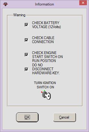
11 1.7 Power up to Automatically Install Drivers Having completed Step 6, the system will now be powered up. The VCM is powered by the battery of the motorcycle. Make sure the ignition is ON and the RUN switch is ON. The light on the VCM should be lit. This will cause the software to search for the cable drivers. This will prompt you to select the folder called USB 2.0 Cable Drivers. The software will find and install the drivers. 1.8 Update Your Software After the Centurion software is installed, you must run the updater to get the latest program versions, including the calibrations and the manuals. Click the Updater icon at the bottom of the opening screen. 9
, 3AMP, or Sicma connector cable in the kit,")
12 2. Connect the Centurion Hardware 2.1 Connect the Centurion U/UE/M/S Hardware Connect the Centurion U/UE/M/S Hardware and the motorcycle's data link connector using the Deutz (4 pin or 6 pin), 3AMP, or Sicma connector cable in the kit, as well as the alligator clips to the battery. Location of diagnostic connector varies from motorcycle to motorcycle. For show purposes, a Ducati Monster with 3AMP connector was used. To avoid damaging the cables, keep them clear of the exhaust TIP: If your bike does not have a headlight OFF/ON switch, you might want to take out the fuse so that the battery doesn t die. 2.2 Connect the USB cable Connect the Centurion U/UE/M/S Hardware to the computer using the USB cable in the kit. 2.3 Insert Security Key into USB (For Pro users only) Connect the USB security key to a second USB port on your computer. 10
 If you haven t done so already, insert the USB Hardware Key into your computer s USB port to use the Centurion U/UE/M software (Pro versions only).")
13 3. Starting your Centurion U/UE/M/S software 3.1 Insert Security Key into USB (For Pro users only) If you haven t done so already, insert the USB Hardware Key into your computer s USB port to use the Centurion U/UE/M software (Pro versions only). For Centurion-S users, make sure your Centurion tool is properly connected to the vehicle s battery and that the ignition and Run/Stop switches are in the ON position. 3.2 Run the program Click Centurion U/UE/M/S icon on the desktop to run the software. 11

14 3.3 Disclaimer/Language selection Click Accept to approve the disclaimer. For single user, select Centurion Standard and your language of choice: 12

15 For shops or users with multiple bikes, select Centurion Pro and your language of choice: 3.4 Select the COM Port Go to Communication tab and select Port Setting. The correct port should be selected automatically, but if it is not, you will need to follow the instructions in
16 3.5 COM Port Setting Go to your computers Control Panel, select Hardware and Sound, select Device Manager. If COM port is not showing, you will get this message: IMPORTANT: This means that the driver was not correctly installed when installing the Centurion U/UE/M/S software. When you right click and select Update Driver Software, you must manually browse and point the search at your CD/DVD drive if the software CD is in it, OR save the software download from the web and point to that. Note: These screen shots were taken on a Windows 7Pro equipped computer. Your computer might look different. After you have updated or installed the correct device driver, you should get a screen like this: Go back to the Port Setting window in your software and make sure the corresponding number is selected in this case, you would select COM14. 14

17 4. Using the Centurion U/UE/M/S 4.1 Connecting to Your Motorcycle and Key Features: In order to display the data you wish to monitor, you must first establish a connection with the ECU and then set the program to either dashboard mode or strip chart mode. To establish communication*, select the Brand/ECU/Model command, either by clicking on the icon or by using the Options drop down menu. *IMPORTANT: If you have a Pro model, U/UE/M, you must first select the motorcycle or ECU model you are connecting to for the software to correctly select the data. You do this by clicking on the Motorcycle icon, and then selecting the brand, ECU and model. For Centurion-S users, you must click the Motorcycle icon to configure the cable to your bike. 15

18 After the Brand/ECU/Model is selected (or for Centurion-S, after your cable is connected and you select the bike icon to configure), select the Connect icon. Note: When communication with the ECU is lost or could not be established, the data will not be able to be displayed and an error message dialog box will come up. 4.2 Main Menu The Centurion main menu offers a variety of commands. To open the menus and see the available commands, either point and left click on the menu name, or press ALT + the underlined letter in the name of the menu you wish to open. Below the main menu are the Toolbar Buttons, which offer quick access to the most often used commands. 16
19 4.3 Tab Menu File Menu: Commands to open a file, export one, close an active window and quit the program View Menu: Contains commands related to data monitoring Communications Menu: Commands for connecting to the ECU, disconnecting from the ECU and selecting port settings Options Menu: Commands to select log settings, toggle log on or off, select O2/Gas Analyzer, select the ECU or model, and select channels, units and color settings Utilities Menu: Contains the calculator and unit conversions Help Menu: Displays a variety of help commands 17
20 4.4 Centurion Toolbar Buttons (for both Single and Pro Users) The toolbar buttons allow one-click access to the most frequently used commands. Click to: Open data analysis Print Monitor data in dashboard (gauges/meters) mode Monitor data in strip chart mode Horizontal Slide Bars Active Test Active Settings View Diagnostic Trouble Codes Establish connection with ECU Disconnect from ECU Log on and Log off data recording Select brand/ecu/model Select data channel to be monitored Metric/English unit conversions Activate the calculator 18
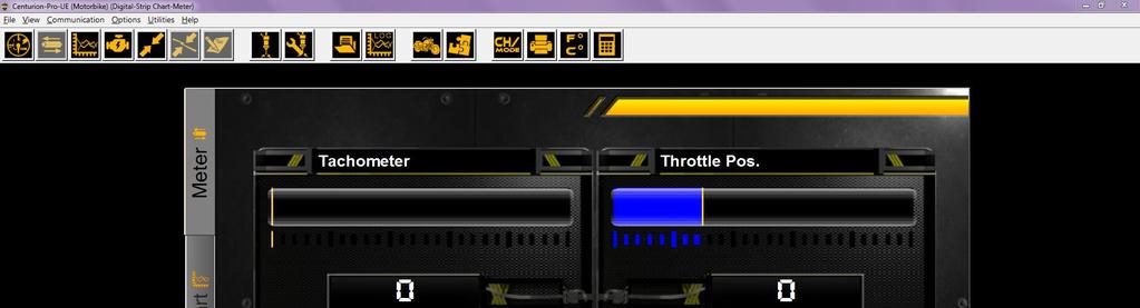
21 5. Toolbar Icon Description (for both Single and Pro Users) 5.1 Toolbar Buttons/Commands In-Depth Open Data Log for Analysis Opens a dialog box, where you can open the file with the data log that has been created. Please note: to make this feature available, you must first set the Recording feature to On. If it is set to Off, a log will not be created. The software will create a filename for your data log based on date (and sequence, if applicable). Print Prints a copy of your data log Gauges/Meters The Gauges/Meters button enables viewing of data through bar slides, graphs, thermometers and check lights. It offers 6 configurable channels. Please note that the round gauges at the top of this screen are not configurable; those four gauges are set to always show those four data elements. Strip Chart The Strip Chart Monitor button is used to view data in line plot and numerical form. It offers 16 configurable channels. Horizontal Slide Bars The Horizontal Slide Bars button is used to view data with horizontal slide bars. It offers 4 configurable channels. 19
22 TIP: Most Commonly-Used Channels (Gauges/Meters, Strip Chart & Horizontal Bar Slides Viewing Modes) RPM: Engine RPM numeric value Battery: Battery voltage numeric value Spark Advance: Spark adv. angle numeric value Pulse Width: Pulse width numeric value Injec on me Throttle Position: Throttle angle numeric value Air Temperature: Air temperature numeric value Engine Temperature: Engine temperature numeric value Barometric Pressure: Barometric pressure numeric value Stepper Motor: Stepper motor numeric value (Please note that any data element that is grayed out is not available for that ECU.) 5.2 Gauges/Meters Window 20


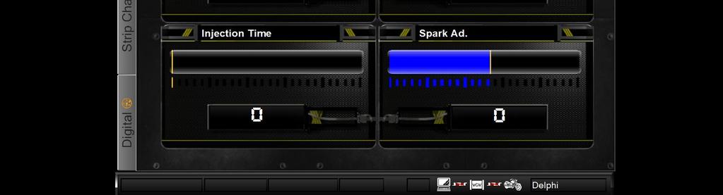
23 5.3 Strip Chart Window 5.4 Horizontal Slide Bars Window 21
24 5.5 Active Test This window has several functions including testing the actuators and adjusting the Trim EEPROM. This window is used to perform several operations, such as the Clear DTC button will clear readings from the Historic box of the DTC window. *Features dependent on ECU Active Test Definitions System: System relay, fuel and coolant pumps. LED: ABS, battery, cruise, engine, 6 th gear, low fuel, security tell tail, security lamp and alarm LEDs. Speedometer: Tachometer and speedometer. ABS Solenoid: Front & rear/apply & release, ABS and rear pumps. TSSM: Left and right turn signals. Actuators: ACR and throttle actuator. ACR: Air compression release. EITMS: Engine idle temperature management system. Fans: Cooling fan. Adjust Idle Speed: Change and test idle speed. Injectors: Injectors 1 and 2. Coils: Coils 1 and 2. 22
25 5.5.2 TSSM testing Harley Davidson Only 5.6 Active Settings This window is used to perform several operations. (The Clear DTC button will clear readings from the Historic box of the DTC window). 23

26 5.6.1 Active Settings Definitions DTC: Read and clear current and historic diagnostic trouble codes. Speedometer Calibration: Validate speedometer output against the true traveling speed of the bike. KeyFob: Program or reprogram a new or damaged keyfob, enable/disable alarm. Idle Adjustment: Calibrate idle RPM. TPS Setting: Adjust and calibrate throttle position sensor. Immobilizer: Theft recovery and reset. ECU Programming: Marry a blank ECU to the TSSM, HFSM or BCM, and program a VIN. ABS Bleeding: Service/bleed front and rear brakes. Module Replacement: Enable/Disable: EITMS, ACR, exhaust, IAC, side stand and cruise control. Radio & Speakers: Program radio zone and speaker selection. 24

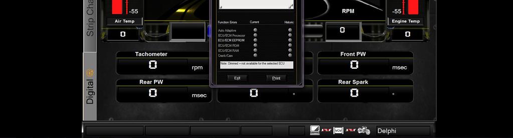
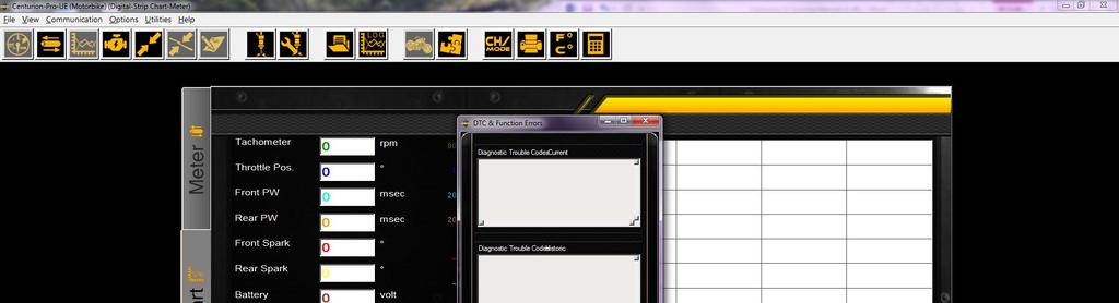
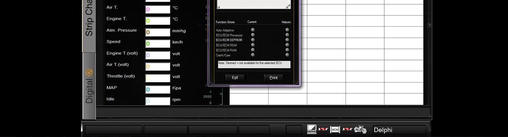
27 5.6.2 DTC Read While in Gauges-Meters mode: OR While in Strip Chart mode: 25
28 5.6.3 Diagnostic Trouble Code & Function Errors This window displays both current errors (even those that may appear very briefly), as well as historic errors. Please note that current errors that appear very briefly may not show in the historic box. 26
29 O.C. = open circuit S.C. = short circuit High V. = high voltage Low V. = low voltage 27


30 6. How to Change Units/Colors 6.1 How to change units Go to Options menu and select Units. Select the unit that you want to use. Click OK. 6.2 How to change colors Go to "Options" menu and select "Colors". Select the unit that you want to use. Click "OK". 28

31 6.1.2 Select channel for color change Select the channel of which you want to change the color Select color Select the color you want. You can also change the background. 29

32 7. Monitor Real-time data (Gauges/Meter display) 7.1 Monitor Data Monitor the Real-time data with Gauges/Meters display. Go to View and select Gauges/Meters, or just click Gauges/ Meters icon. 7.2 Change Channels If you want to change the visible data, go to Options and select Channels/Mode, or just click Channels/Mode icon. The small Gauges-Meters window will open: 30


33 7.3 Change Visible Parameter There are six channels. Click the gray square button for the drop down menu if you want to change the visible parameter Select Parameter Select a parameter that you want to display. Click OK. 31
34 For best monitoring the engine, we recommend to select the following 6 channels: 1. Tachometer - RPM 2. Throttle Position 3. Engine Temp 4. Battery Voltage 5. Air Temp 6. Atm Pressure Any other information is optional and up to personal preferences. 7.5 Communicate Turn on the ignition switch and make sure the engine stop switch is in the RUN position. Go to Communication and select Connect or just click Connect icon. 32
35 8. Monitor Real-time data (Strip Chart display) 8.1 View Data Monitor the Real-time data with Strip Chart display. Go to View and select Strip Chart or just click Strip Chart icon. 8.2 Turn ignition to run Turn on the ignition switch and make sure the engine stop switch is in the RUN position. 8.3 Communication Go to Communication and select Connect or just click Connect icon. 8.4 Start Engine Start the engine. Now you can monitor Real-time data. 8.5 Channel Mode If you want to change the showing parameter, go to Options and select Channels/Mode or just click Channels/Mode icon. 33


36 8.6 Channel display You can display up to sixteen channels at a time. If you want to increase or reduce the number of channels, click on/off switch. ON: Show the selected channel. OFF: Hide the selected channel. 34


37 8.7 Select Parameter Click on the Arrow button if you want to change the visible parameter. Select a parameter that you want to display and then click OK. 8.8 Select Display Select Parallel display or Overlay display. Click OK. 35
, choose your ECU, then click OK. 9.")
38 9. Harley-Davidson Tests and Activations 9.1 Specific Functions Select the ECU type you are testing by clicking on the Motorcycle icon for Brand/ECU. Select Harley Davidson and then the drop down menu (for HD, it will only show ECU/ECM type), choose your ECU, then click OK. 9.2 Connecting Turn ON the ignition switch and make sure the engine stop/run switch is in the RUN position. Click CONNECT. 36
39 9.3 Select the procedure you want to perform *PLEASE NOTE THAT INJECTOR TESTING CANNOT BE PERFORMED ON BIKE INJECTORS MUST BE TAKEN OFF AND BENCH TESTED. Active Tests Active Settings OR DTCs OR 37
40 9.4 Select function After you have selected the procedure, select the function you want. *Features dependent on ECU features shown are for Delphi: Active Test Active Settings Active settings allow you to change the values of some parameters as long as they were changeable from the factory. 38
 4. Engine will die 5. Wait 10 seconds 6.")
41 9.5 Specific functions for Harley-Davidson motorcycles Module Programming 1. Select the idle module replacement tab on Active Settings 2. Click on Calibrate 3. Prompt will ask you to start the engine (Do not click OK before starting the engine) 4. Engine will die 5. Wait 10 seconds 6. Click OK 39

42 9.5.2 ABS Bleeding 1. Select ABS from Active Settings drop down list 2. Read the disclaimer and click Accept for the setting to become live 3. Select which breaks you are going to work on 4. Follow instructions on screen 5. Hold brake lever with constant pressure. After you have finished, click OK 6. Repeat same procedure for the other brake 40
43 *INSTRUCTIONS ARE BASED ON HAVING EXPERIENCE PERFORMING A MECHANICAL BLEEDING PROCEDURE!!! KeyFob Programming 1. Select KeyFob from Active Settings drop down list 2. Click on the KeyFob button to test the system 3. Number each KeyFob as Number 1 and Number 2. Open them to make sure that the codes displayed are correct 41
44 4. Write the new KeyFob s code where the damaged KeyFob code was Alarm Disable/Enable 1. Select KeyFob from Active Settings drop down list 42
45 2. Write your personal key code 3. Select On/Off 4. Click Program 43
46 10. Location of diagnostic connectors 10.1 Location of diagnostic connector in Harley Davidson Motorcycles Softail Models Located under the seat*, attached to the frame by the rear fender. Plug is grey in color, with black rubber plug installed. *Requires removing the seat Dyna Models Located behind the left side cover. Connector is light grey in color with black rubber plug installed Sportster Models (includes XR Models) Located behind the Lh side cover. Plug is Grey in color with black rubber plug installed V-Rod Models Diagnostic connector is located behind the right front frame cover.* Plug is grey in color with black rubber plug installed. *You will need tools to remove the cover Touring Models Diagnostic connector is located behind the right hand side cover.* Plug is grey in color with black rubber plug installed. *Accessible by removing the right side saddle bag Touring Models Diagnostic connector is located behind the left hand side cover.* Plug is grey in color with a black rubber plug installed. *Accessible by removing the left side saddle bag. 44
47 Glossary ECM/ECU (Electronic control module/unit): This is the brain of the motorcycle; it makes calculations based on inputs coming from sensors mounted all over the engine. WOT (Wide open throttle): The maximum opening of the throttle valve. AFR (Air fuel ratio): The relationship of parts of fuel to the parts of air. 13.0(air) to 1(fuel) usually makes the best power, and 14.6 is considered perfect air fuel ratio. This would be the AFR to get an ideal burn (theoretically). This would be at perfect atmospheric conditions and temps, with a perfect atomization which is almost impossible. MAP (Manifold absolute pressure): These sensors measure barometric absolute pressure in the intake manifold. By calculating the mass of the air going into the engine, air temperature, and the rotations per minute of the engine, the engine s ECU can determine the density of the air flowing into the fuel mixture. The ECU can then adjust air flow or fuel flow. CKP or CP (Crank position sensor): This sensor tells the ECM when to fire and inject fuel depending on how fast the engine is running in Revolutions Per Minute. IAT (Intake air temperature): The ECM calculates how dense the air is from this input. ET (Engine temperature): The ECM uses the signals from this sensor to determine if the engine is at operating temperature, or warming up. Fuel Pressure Regulator: A mechanical device usually operated by vacuum form intake manifold that controls fuel pressure. It returns excess fuel from the fuel pump back to the fuel tank. Fuel Injectors: The fuel injectors are electric valves that open and close to deliver fuel in spray form to the cylinder. They are controlled by the ECM to precisely deliver the correct amount of fuel at every engine speed or RPM and any given load. The time of injection is also known as the injector pulse width and is measured in milliseconds. Injectors are rated by their flow rate such as in gm/sec, l/hr or grams per second. Electric Fuel Pump or Fuel Pump: A 12-volt high-pressure fuel pump, usually located in the fuel tank, but it can be located outside as well. It supplies pressurized fuel to the fuel injectors. 45
48 IAC (Idle air control): An electric valve that s threaded, to open and close as needed to let air into the engine for startup and idle operation when throttle valve is closed. Closed Loop injection system: This circuit has 2 Oxygen sensors. The information on the difference of how much is coming out of the cylinder is relayed to the ECM and then adjusts the amount of fuel injected by shortening or lengthening the time the injectors are open. O2 Oxygen sensor (sniffer): This tells the ECM how much oxygen is in the exhaust mixture so as to have the correct mixture. Anything under 14.7 is considered a rich mixture and anything above 14.7 is considered a lean mixture. RPM (Revolutions per minute): Used to measure engine speed. TPS (Throttle position sensor): You will be dealing with percentages (0 to 100) or Degrees ( ) and/or Volts (V). DDM (Drop down menu): selection of parameters available for a field. 46

49 DIRECT LINK FLASH TUNER Installation and User Manual This Guide is intended to answer basic Direct Link tuning questions and to act as a Quick Start Guide. It is not intended to be encyclopedic on the tuning process - only to answer basic questions about Direct Link. This Guide will give some example tables that have been proven to work in the past, but the tuner/dealer is ultimately responsible for the final tune on any bike.
50 INTRODUCTION... 3 HOW IT WORKS... 3 ABOUT THIS MANUAL SETUP AND INSTALLATION WHERE TO GET THE SOFTWARE INSTALL DIRECT LINK FLASH TUNER RUN DIRECT LINK FLASH TUNER INSERT SECURITY KEY INTO USB CONNECT USB CABLE POWER UP THE DIRECT LINK FLASH TUNER POWER UP TO AUTOMATICALLY INSTALL DRIVERS UPDATE YOUR SOFTWARE CONNECT THE DIRECT LINK HARDWARE CONNECT THE DIRECT LINK TO YOUR MOTORCYCLE CONNECT THE USB CABLE AND USB KEY STARTING YOUR DIRECT LINK SOFTWARE SECURITY KEY AND CABLE RUN THE PROGRAM DISCLAIMER/LANGUAGE SELECTION SELECT THE COM PORT COM PORT SETTING IF NONE IS SHOWING AND NO OTHER OPTION IS GIVEN TOOLBAR ICON DESCRIPTIONS MAIN MENU TAB MENU DIRECT LINK TOOLBAR BUTTONS KEY FEATURES CREATING A BACKUP LOADING A MAP IMPORTANT TABLES VE Table Spark Table AFR Ratio Table Cranking Fuel Idle Table IAC Table Acceleration Table Decel (Deceleration) Table Closed Loop Warm-up Fuel table ADDITIONAL CHECKS Knock Sensor Engine Parameters Calibration Note Throttle grip PROGRAM THE CALIBRATION INTO THE ECU
51 6.1 SAVE ORIGINAL CALIBRATION CHECK ECU INFORMATION SELECT CALIBRATION RUN PROGRAM PROGRAMMING STATUS HOW TO SAVE THE MODIFIED CALIBRATION SAVE AS CALIBRATION INFORMATION HOW TO CHANGE UNITS OPTIONS MONITOR REAL-TIME DATA (GAUGES/METER DISPLAY) MONITOR DATA CHANGE CHANNELS CHANGE VISIBLE PARAMETER SELECT PARAMETER TURN IGNITION TO RUN COMMUNICATE MONITOR REAL-TIME DATA (STRIP CHART DISPLAY/METER DISPLAY) VIEW DATA TURN IGNITION TO RUN COMMUNICATION START ENGINE CHANNEL DISPLAY SELECT PARAMETER SELECT DISPLAY AUTO-MAPPING SELECT STRIP CHART LOGGING DATA WITH A DYNO LOGGING DATA WITH MOBILE DYNO GLOSSARY
52 Introduction The Direct Link Kit will provide the tuner with the tools and necessary data to maximize the potential of the installed upgrades. The system is designed for Harley-Davidson Fuel Injection equipped motorbikes. How it Works The ECU is basically a calculator that sends signals to the injectors. The sensors include the temperature of the motor (Harleys head temperature sensor), outside ambient temperature and pressure (altitude), throttle position (TPS), engine speed (RPM) and load (KPA or MAP, manifold absolute pressure). The newer models, (2008 and later), also have a narrow band O2 sensor and actually run in closed loop when you tell it to. The ECU combines all data gathered by the above mentioned sensors and compares it to the scribed maps that have been set up at the factory and makes adjustments so that the engine works at its best given the circumstances. About this Manual The Direct Link User s Guide is a comprehensive guide that contains procedures you will need in order to work with this software. This manual is organized by chapters to assist novice users with getting started. Many topics covered in this manual are also covered in the help menus available in the program itself. This Guide/Manual has been written thinking that not only professionals will use it, but also non-professionals. That is the reason it is written in a non-technical way. 3


53 1. Setup and Installation 1.1 Where to get the Software Insert the CD-ROM from TechnoResearch Inc. into the DVD/CD-ROM drive of the computer OR download from our website ( go to Support > Downloads). 4

54 1.2 Install Direct Link Flash Tuner After auto-run, press install and follow the installation prompts. 1.3 Run Direct Link Flash Tuner Double-click on the Direct Link Flash-Tuner icon on the desk top to run the program. This will install the USB security hardware key driver necessary for step 4. 5


55 1.4 Insert Security Key into USB Insert the product security hardware key, (provided pre-programmed USB), into the USB port of the computer. This will enable the software to run. 1.5 Connect USB Cable Connect the USB computer cable (shown below at left) to the Vehicle Communication Module. The module is shown below, with the USB port on the right side of the metal endplate. Connect the other end to the PC s second USB port. 6

56 NOTES: The supplied USB Hardware Key with this software is for use on a single vehicle only. When the USB Hardware Key is used to program a vehicle, it will be permanently attached to that vehicle, and cannot be used on any other for programming. You can use any key, empty or used, to start and use this software. Only when programming will the software check that the key is empty and lock it to THAT ECU. If the key has been used before, the software will check that the key will match the ECU. If not, the software will be closed. NEVER plug in multiple hardware keys. For example: do not plug in a Direct Link key and a Centurion key at the same time! 1.6 Power up the Direct Link Flash Tuner Connect the Vehicle Communication Cable to the DB-15 port on the other end of the Vehicle Communication Module (shown below). Connect the other end to the motorcycle s data link connector. If you cannot locate your bike s data link connector, please consult your motorcycle user manual. 1.7 Power up to Automatically Install Drivers Having completed Step 6, the system will now be powered up. The VCM is powered by the battery of the motorcycle. Make sure the ignition is ON and the RUN switch is ON. The light on the VCM should be lit. This will cause the software to search for the cable drivers. This will prompt to select the folder called USB 2.0 Cable Drivers. The software will find and install the drivers. 7
57 1.8 Update the Software After the Direct Link software is installed, run the updater to get the latest program versions including the calibrations and the manuals. Click Updater in the bottom right corner: 8
58 2. Connect the Direct Link Hardware 2.1 Connect the Direct Link to a Motorcycle Connect the Direct Link Flash Tuner and the motorcycle's data link connector using the data link connector cable (4 pin or 6 pin) in the kit. Location of Data link connector: Touring models: Underneath the right side cover. ( Underneath the left side cover) Softail models: Underneath the seat. Dyna models: Underneath the left side cover. Sportster models: Underneath the left side cover. VRSC: Underneath the front side neck cover. 2.2 Connect the USB Cable and USB Key Connect the Direct Link hardware USB cable and USB key to the computer. 9

59 3. Starting the Direct Link Software 3.1 Security Key and Cable Make sure the hardware is connected as shown in Section (above section). 3.2 Run the Program Click Direct Link Race Performance icon on the desktop to run the software. 3.3 Disclaimer/Language selection Click Accept to agree to the terms of use and select a Language preference to launch to software. 10

60 Shown below is the programming screen and where you will do a lot of your work. You should play with this screen and practice opening and closing editing tables and connecting to the motorcycle. Each table you edit will change something on the motorcycle and you will always program the ECU from this screen. 3.4 Select the COM Port Under Communication, select Port Setting. Important: If the Direct Link hardware (VCM) is not powered, then the correct COM Port will not appear (indicated by an illuminated LED). To rectify, press Cancel and power the Direct Link hardware by turning on the ignition switch and making sure the engine stop/run switch is in the RUN position. Once the LED light is on, the Direct Link hardware is on, select Communication and Port Setting again to select the correct COM Port. 11

61 3.5 COM Port Setting if None is showing and No Other Option is Given If the COM port is not showing, it means that the driver for it was not correctly installed when installing the software. Go to the computers Control Panel, select Hardware and Sound, select Device Manager. If the COM port is not showing, the yellow triangle icon will appear: IMPORTANT: This means that the driver was not correctly installed when installing the Centurion U/UE/M/S software. When you right click and select Update Driver Software, you can manually browse and point the search at your CD/DVD drive if the software CD is in, OR search automatically and the files should be pulled. 12
62 After the correct device driver is installed or updated, the window will look like this: Go back to the Port Setting window in the software and make sure the corresponding number is selected in this case, COM14. 13
63 4. Toolbar Icon Descriptions 4.1 Main Menu The Direct Link main menu offers a variety of commands. Below the main menu are the Toolbar Buttons, which offer quick access to the most often used commands. 4.2 Tab Menu File Menu: Commands to open, export, backup or save a file, close an active window, and quit the program Edit-Table: Access to editable tables and engine settings View Menu: Contains commands related to what mode you are viewing Communication: Commands for connecting, disconnecting, and programming Options: Trace and data record settings, access to Mobile Dyno, settings to change units and colors Help: Displays a variety of help commands 14
64 4.3 Direct Link Toolbar Buttons The toolbar buttons allow one-click access to the most frequently used commands. Open Calibration Open Data Log Save As Print Reflash Gauges/Meters Strip Chart PVI Connect Disconnect Recording ON/OFF Channels/Mode Auto map/mobile Dyno Front & Rear Fuel Table Front & Rear Spark Table AFR Table 15
65 5. Key Features 5.1 Creating a Backup Note: Always save the original calibration before programming the new calibration. That way, the motorcycle can be restored to stock at any time. Precautions: During the backup and programming, the ECU must be powered correctly. Therefore, we recommend removing the LIGHT fuse and using a charger to be sure that the voltage is correct. With the ignition switch on and the engine stop switch in the RUN position, click Backup Original Map. This will back up the original map from the ECU so that, at a later date, the motorcycle can be restored to stock if needed. 16
66 Select a location and name for the Backup Map and click on Save Direct Link will now read and save the original bike map. After the status bar has reached 100, check for the green PASS to ensure that all operations have concluded successfully. Note: Do not disconnect the USB Hardware Key. This could damage the key. 17
67 5.2 Loading a Map Before loading a map, check what map is in the motorcycle ECU by pressing the button ECU Info. The application # will show the correct map model (105, 127, 176, etc.) Open a calibration via File > Open Calibration > Modified or click the Open Calibration icon. This will open a file selection window. Find the map best suited to load and click Load. (The Application # mentioned above is usually in the end of the map file name. The Info button next to the app # can be used as a quick reference for matching). 18
68 Once loaded, the Calibration Information can be reviewed and compared with that of the ECU. 19
69 5.3 Important Tables (Check before first flash) The following tables can be found under the Edit-Table drop down, or by using the toolbar buttons shown: VE Table 20
70 5.3.2 Spark Table 21
71 5.3.3 AFR Ratio Table The values in the AFR (Air-Fuel Ratio) table are calculations that the ECU uses to determine the injector pulse width. The AFR does not actually change. This is the main fuel table that the ECU will try to achieve. The tuning process changes the VE (Volumetric Efficiency) tables so that the live AFR data is as close to AFR table. You can, and should, change the VE s on each cylinder separately. They each have different requirements and the fuel injectors may not be matched for flow. There are (2) methods to accomplish this Set the AFR Ratio Table in open loop but close to the final Target values. The other method is to set all of the values to the same constant ( ). Once the values are in place, click on the Apply button to apply the changes, then the OK button to conclude the modification. Note: When working on the closed-loop models, changing the AFR value to anything other than 14.6 disables closed-loop operation which makes VE table tuning possible. 22
72 5.3.4 Cranking Fuel Make sure to check this table. The cold temperature numbers should have more fuel than the hot temperature numbers. Double click on an msec cell and use the up and down arrow to adjust. The values above a temperature of 233F may have to be adjusted up or down to get the bike to start quickly. Click OK. See this example of a typical Cranking Fuel table: 23
73 5.3.5 Idle Table Make sure to check this table. Double click on an RPM cell and use the up and down arrow to adjust. Remember to let the engine get to working temperature before making any changes. Click OK. See this example of a typical idle table: 24
74 5.3.6 IAC Table Make sure to check this table. This table may need to be adjusted while tuning to make sure bike is idling up on startup, and when at operating temperature, the idle is stable. Check live data and verify that the actual stepper counts are not lower than the programmed stepper counts. The actual Steps should be the same or slightly lower than the programmed values. Double click on a STEPS cell and use the up and down arrow to adjust. Click OK. See this example of a typical IAC Table: 25
75 5.3.7 Acceleration Table Make sure to check this table. The accel table needs to be adjusted during tuning so the bike will have crisp response when blipping the throttle and no black smoke comes out of the exhaust. Double click on a STEPS cell and use the up and down arrow to adjust. Click OK. TIP: Create a table that lists the changes in calibrations that have been modified just in case you want to go over your own work before saving. 26
76 5.3.8 Decel (Deceleration) Table Make sure to check this table during tuning if decel popping is occurring. This table allows the removal of a small amount of fuel during a decrease in throttle position, or during a decrease in manifold pressure. This fuel gets subtracted from the base pulse width calculation. Larger values increase the fuel removed. Smaller values decrease the fuel removed. Double click on a STEPS cell and use the up and down arrow to adjust. Click OK. 27
77 5.3.9 Closed Loop This table can be left alone for tuning, as the AFR Table has been set so the bike will always be in open loop and not be using the factory Oxygen sensors. Only when the AFR table is at 14.6 will this table be active and used. There are (2) types of closed loop systems now. The older bikes use closed loop biasing and the new bikes do not. The new bikes can be set from for closed loop. The old bikes with the bias table have the AFR value or millivolt setting centered at 450volts. Setting this table to 680 will yield something like AFR Value. You cannot set this mv value much higher, as the O2 sensor will not switch properly and will drive the fuel rich. The sensor needs to switch around a center point. 28
78 Warm-up Fuel table Make sure to check this table. This table needs to be minimized as much as possible so gas is not being wasted on warm-up. Double click on an AFR cell and use the up and down arrow to adjust. Click OK. See this example of a typical Warm-up Fuel Table: 29
79 5.4 Additional Checks (Check before first flash) The following tables can be found under the Edit-Table menu, or by using the toolbar buttons shown: Knock Sensor This should be turned on when the timing table is being adjusted and click OK to save Engine Parameters The settings for Engine size and injector size should be set to match what the engine really is. These parameters may need to be adjusted to alter the VE tables off of maximum values. Try to leave the cubic inch values matched to the motor and move the injector values to allow the VE tables to be in spec. Click on a parameter and use the arrows to adjust. Click OK to save. 30
80 5.4.3 Calibration Note It is a good idea to detail what modifications the engine has CAMS, pipes, air box, etc. (It is recommended that First ECU flash is noted when applicable). 31
81 5.4.4 Throttle grip This table sets the maximum throttle valve opening at a specific throttle grip setting and RPM. This table needs to be set before any tuning is done. All of the tables have been checked and it is time to flash the ECU for the first time. We will be flashing many times once the tuning of the VE tables and the adjustment of the spark tables starts. The first flash has to be done to register all of the changes just made. After this we start the tuning process. Note: A re-flash is always necessary for any changes to take effect. 32
82 6. Program the Calibration into the ECU For all practical purposes, this describes what to do on a relatively stock or only slightly modified motor (cams, pipes, air breather and/or heads). 6.1 Save Original Calibration After saving the original calibration (see 5.1), start to tune the calibration. Note: Open the Edit-Table menu and click on Engine Setting. The displacement can be set if you ve changed that and the injector size. This is very handy because if the injectors are changed later, the software can input the new size and it will compensate for larger injectors or a big bore kit. 33
83 6.2 Check ECU Information Check the current motorcycle ECU information first by pressing ECU Info (see 5.2 for more details). 34
84 6.3 Select Calibration Select a starting calibration or modified calibration that most closely matches the motorcycles current setup (see 5.2 for more details). Click Load. 6.4 Run Turn on the ignition switch and make sure the engine stop switch is in the RUN position. 35
85 6.5 Program Go to Communication menu and select Program or just click Program button to upload new calibration into the ECU. Note: Do not disconnect the Direct Link key. This could damage the key. This will load a map into the system. The processing status is indicated on the progress status bar: 6.6 Programming Status At the end of the programming mode, a PASS or FAIL message will be displayed. FAIL: If during the programming an error message/fail message appears, disconnect the ECM/ECU for 30 seconds, then reconnect, and begin programming again. Please also double check the wiring and adaptors being used. (Note: If this message persists, remove all the fuses and relays from the fuse box of the bike except the ECM/ECU and ignition fuses. Reprogram the ECM/ECU and put back all the fuses.) PASS: After successfully programming the ECU, turn ignition off, wait 10 seconds and turn ignition on again. Then start and run the bike. 36

86 7. How to Save the Modified Calibration 7.1 Save as Click the Save as icon or go to File menu and select Save As. Note: Always save the original calibration before programming the new calibration. That way, the motorcycle can be restored to stock at any time. Type a new file name. Click Save. TIP: Name the file a special name so you don t have any problems finding and opening the new modified file. You should always retrieve your stock tune and save it before you make any changes so you can go back to the stock tune in case any errors were made. 37
87 7.3 Calibration Information Calibration ID and Calibration Note can be edited or modified. Click OK when finished. 8. How to Change Units 8.1 Options Go to Options menu and select Units. Select the preferred unit. Click OK. 38

88 9. Monitor Real-time Data (Gauges/Meter Display) 9.1 Monitor Data Monitor the Real-time data with Gauges/Meters display. Go to View and select Gauges/Meters or just click Gauges/ Meters icon. 9.2 Change Channels To change the visible data, go to Options and select Channels/Mode (or just click Channels/Mode icon). 39


89 9.3 Change Visible Parameter There are six channels. Click the gray square button to change the visible parameter. 9.4 Select Parameter Select the parameters to display. Click OK. 40
90 9.5 Turn Ignition to Run Turn on the ignition switch and make sure the engine stop switch is in the RUN position. 9.6 Communicate Go to Communication and select Connect or just click Connect icon. 41

91 10. Monitor Real-time Data (Strip Chart display/meter Display) 10.1 View Data Monitor the Real-time data with Strip Chart display. Go to View and select Strip Chart or just click Strip Chart icon. 42
92 Open the Channel/Mode window. Consider adding engine (temp) to make sure you re never running the engine hot when recording and the motor is in the operating temp range. Starting at the top: Thro (TPS), Tacho (engine speed), and Ext O2 #1 (comes from the O2 sensor output), MAP (manifold absolute pressure or load) 43
93 For best tuning, we recommend to select the following 10 channels: Tachometer - RPM Throttle Pos Engine Temp AFR Desired MAP Load Knock Front Knock Rear Idle Ext O2 #1 Ext O2 # Turn Ignition to Run Turn on the ignition switch and make sure the engine stop switch is in the RUN position Communication Go to Communication and select Connect or select the Connect icon. 44
94 10.4 Start Engine Start the engine. Real-time data can be monitored by going back into Channel/Mode while in Strip Chart display Channel Display Up to sixteen channels at a time can be displayed. To increase or reduce the number of channels, click the on/off switch. ON: Show the selected channel. OFF: Hide the selected channel. 45

95 10.6 Select Parameter Click on the Arrow button to change the visible parameter. Select a parameter to be displayed. 46
96 10.7 Select Display Select Parallel display or Overlay display. Click OK. 47
97 11. Auto-mapping Connect the hardware and open the Direct Link software. Follow steps for saving and loading the map. Program the ECU Select Strip Chart Select the following channels by selecting the Channels/Mode button. The software will not continue if these channels are not selected: Tacho:Engine RPM MAP: KPa Throttle Position: Throttle position in degrees Battery: Batt V AFR Desired: VE 1: VE C1 % VE 2: VE C2 % New VE 1 New VE 2 Ext O2 #1: AFR 1 Ext O2 #2: AFR 2 You will get a prompt from the system letting you know that you MUST select these channels in order to Automap. NOTE: Make sure the starter map you want is loaded and programmed before continuing. 48
98 11.2 Logging Data with a Dyno While in Strip Chart mode, click Connect and wait for the bike to connect. Select the Auto Map icon. Select Dyno and click OK. Click Start Session. 49
99 When finished logging, click End Session. A prompt will open click OK to automatically load the log. TIP: To open previous Logging Sessions click the Open Log icon ( ), select the run and click Load. Click Create Map. Choose the tables to be modified and the O2 sensors that were used. Make changes to the VE Tables and click OK when finished. To save, click the Save icon ( ). Now go back to the re-flash screen ( ), open the new calibration and program it to the ECU. NOTE: Make sure to BACKUP the original calibration so the motorcycle can be restored back to stock if necessary. 50
100 11.3 Logging Data with Mobile Dyno NOTE: Be sure the same channels shown in 11.1 are selected. Select the Auto Map icon. Select Mobile Dyno and click OK. Click Start Session. A prompt will ask to configure the VCM. Select Yes. Unplug the VCM from the computer and the motorcycle (the VCM s power source). The next time the box gets power, it will begin recording. When ready to ride, connect the box to the bike again. It will now begin to log data (up to ~15 minutes worth). The green LED on the VCM will blink, signifying that it is recording. When finished logging, turn the bike off for at least 15s. Connect the VCM back up to the computer and turn the bike back on. Select End Session. 51
101 The log file will automatically download and then load. Click Create Map. 52
102 Choose the tables to be modified and the O2 sensors that were used. Make changes to the VE Tables and click OK when finished. To save, click the Save icon ( ). Now go back to the re-flash screen ( ), open the new calibration and program it to the ECU. NOTE: Make sure to BACKUP the original calibration so the motorcycle can be restored back to stock if necessary. 53
103 Glossary ECM/ECU (Electronic control module/unit): This is the brain of the motorcycle; it makes calculations based on inputs coming from sensors mounted all over the engine. WOT (Wide open throttle): The maximum opening of the throttle valve. AFR (Air fuel ratio): The relationship of parts of fuel to the parts of air. 13.0(air) to 1(fuel) usually makes the best power, and 14.6 is considered perfect air fuel ratio. This would be the AFR to get an ideal burn (theoretically). This would be at perfect atmospheric conditions and temps, with a perfect atomization which is almost impossible. VE (Volumetric efficiency): This is the most important part of tuning. If the computer knows the volumetric efficiency, it can decide how much fuel to add to run best. It is how you tell it to add or subtract fuel and is one of only two variables you can adjust to get the AFR correct. The O2 sensor will aid in your adjustments. MAP (Manifold absolute pressure): These sensors measure barometric absolute pressure in the intake manifold. By calculating the mass of the air going into the engine, air temperature, and the rotations per minute of the engine, the engine s ECU can determine the density of the air flowing into the fuel mixture. The ECU can then adjust air flow or fuel flow. CKP or CP (Crank position sensor): This sensor tells the ECM when to fire and inject fuel depending on how fast the engine is running in revolutions per minute. IAT (Intake air temperature): The ECM calculates how dense the air is from this input. ET (Engine temperature): The ECM uses the signals from this sensor to determine if the engine is at operating temperature, or warming up. Fuel Pressure Regulator: A mechanical device usually operated by vacuum form intake manifold that controls fuel pressure. It returns excess fuel from the fuel pump back to the fuel tank. Fuel Injectors: The fuel injectors are electric valves that open and close to deliver fuel in spray form to the cylinder. They are controlled by the ECM to precisely deliver the correct amount of fuel at every engine speed, or RPM, and any given load. The time of injection is also known as the injector pulse width and is measured in milliseconds. Injectors are rated by their flow rate such as in gm/sec, l/hr or grams per second. 54
104 Electric Fuel Pump or Fuel Pump: A 12-volt high-pressure fuel pump, usually located in the fuel tank, but it can be located outside as well. It supplies pressurized fuel to the fuel injectors. IAC (Idle air control): An electric valve that s threaded to open and close as needed. This lets air into the engine for start-up, and idle operation when throttle valve is closed. Closed Loop injection system: This circuit has 2 Oxygen sensors. The information on the difference of how much is coming out of the cylinder is relayed to the ECM and then adjusts the amount of fuel injected by shortening or lengthening the time the injectors are open. O2 Oxygen sensor (sniffer): Tells the ECM how much oxygen is in the exhaust mixture so as to adjust to have the correct mixture. RPM (Revolutions per minute): Used to measure engine speed. TPS (Throttle position sensor): You will be dealing with percentages (0 to 100). 55
105 CENTURION DIAGNOSTIC SOFTWARE Training Workbook This workbook goes over important tests and settings for the Centurion software, and includes space for the trainee to write notes and definitions.
106 Table of Contents IMPORTANT INFORMATION... 3 FEEDBACK VS NO/LIMITED FEEDBACK... 3 PRACTICAL APPLICATION OF THIS KNOWLEDGE ACTIVE TEST SYSTEM System Relay Fuel Pump Coolant Pump LED ABS Lamp Battery Cruise Engine th Gear Low Fuel Security Tell Tail Security Lamp Alarm Left & Right Indicator GAUGES Tachometer Speedometer ABS SOLENOID Front and/or Rear Cylinder Apply Front and/or Rear Cylinder Release ABS Pump & Rear Pump TSSM Left & Right Turn Signal ACTUATORS ACR Throttle Actuator FANS Fan Fan 2 (for 2014+) ADJUST IDLE SPEED ACTIVE SETTINGS DTC SPEEDOMETER CALIBRATION KEYFOB IDLE ADJUSTMENT ECU PROGRAMMING
107 2.6 ABS BLEEDING MODULE REPLACEMENT ENABLE/DISABLE EITMS ACR Exhaust IAC Side Stand Cruise Control RADIO & SPEAKERS Radio Zone Selection Speaker Selection
108 Important Information The following information should be noted before beginning diagnostics on Delphi and Marelli ECUs. Feedback vs No/Limited Feedback Limited/No Feedback: the software will ask the ECU to do something and the ECU will confirm that the request was received, but it will not confirm that the request was actualized. Feedback: the software will ask the ECU to do something and the ECU will confirm that the request was received AND that the request was actualized. The Delphi is a No/Limited Feedback ECU The Marelli is a Feedback ECU Practical Application of This Knowledge When working on a motorcycle powered by a Delphi ECU with Centurion Super Pro, a "Passed" activation on a Fuel Indicator active test means that the ECU has accepted and understands the request to turn on the Fuel Indicator. It is necessary for the technician to confirm that the ECU was able activate that indicator. 3
109 1. Active Test For more information on installing, opening and connecting to the software, see manual pages (See manual page 22 for Active Test definitions) 1.1 System (See manual page 22 for Active Test definitions) 4
110 1.1.1 System Relay Fuel Pump Coolant Pump 5
111 1.2 LED (See manual page 22 for Active Test definitions) 6
112 1.2.1 ABS Lamp Battery Cruise Engine 7
113 th Gear Low Fuel Security Tell Tail Security Lamp Alarm Left & Right Indicator 8
114 1.3 Gauges (See manual page 22 for Active Test definitions) 9
115 1.3.1 Tachometer Speedometer 10
116 1.4 ABS Solenoid (See manual page 22 for Active Test definitions) This feature is only applicable on ABS equipped models 2007 and newer. New ABS systems are much firmer than previous models. 11
117 1.4.1 Front and/or Rear Cylinder Apply Front and/or Rear Cylinder Release ABS Pump & Rear Pump 12
 1.5.")
118 1.5 TSSM (See manual page 22 for Active Test definitions) Left & Right Turn Signal 13
119 1.6 Actuators (See manual page 22 for Active Test definitions) 14
120 1.6.1 ACR ACR Driver is not supported in the ECU prior to Throttle Actuator 15
121 1.7 Fans (See manual page 22 for Active Test definitions) 16
")
122 Fan 1 Fan 2 (for 2014+) 17
")
123 1.8 Adjust Idle Speed (See manual page 22 for Active Test definitions) 18
124 2. Active Settings (See manual pages for Active Settings definitions) 2.1 DTC (See manual pages 25-27) 19
125 20

126 2.2 Speedometer Calibration (See manual pages for Active Settings definitions) 21

127 2.3 KeyFob (See manual pages 41-43) 22
128 2.4 Idle Adjustment (See manual pages for Active Settings definitions) 23
 NOTE: This feature is not for used")
129 2.5 ECU Programming (See manual pages for Active Settings definitions) NOTE: This feature is not for used ECUs. 24

130 2.6 ABS Bleeding (See manual page 40) 25
131 2.7 Module Replacement (See manual page 39) 26
")
132 2.8 Enable/Disable (See manual pages for Active Settings definitions) 27
133 2.8.1 EITMS ACR ACR Driver is not supported in the ECU prior to Exhaust IAC Side Stand (Mostly found in European and police motorcycles) Cruise Control 28


134 2.9 Radio & Speakers (See manual pages for Active Settings definitions) 29
135 2.9.1 Radio Zone Selection Speaker Selection 30


136 DIRECT LINK FLASH TUNER Training Workbook This workbook goes over important tests and settings for the Direct Link software, and includes space for the trainee to write notes and definitions
137 Table of Contents 1. KEY FEATURES CREATING A BACKUP LOADING A MAP OPEN LOOP, CLOSED LOOP, AND HOW THEY AFFECT TUNING AUTO-MAPPING SELECT STRIP CHART AND CHANNELS LOGGING DATA WITH A DYNO LOGGING DATA WITH MOBILE DYNO TABLES FUEL MAP SPARK MAP AFR CRANKING FUEL IDLE IAC ACCELERATION DECELERATION CLOSED LOOP WARM-UP KNOCK SENSOR REV-LIMITER WHEEL NOTCH THROTTLE GRIP
138 1. Key Features For more in depth information on installing and opening the software, see manual pages Creating a Backup NOTE: Always save the original calibration before programming the new calibration. That way, you can restore your motorcycle back to stock. Precautions: During the backup and programming, the ECU must be powered correctly. Therefore, we recommend removing the LIGHT fuse and using a charger to be sure that the voltage is correct. Click Backup Original Map. This will back up the original map from the ECU so that, at a later date, you can restore the motorcycle back to stock if needed. Turn on the ignition switch and make sure the engine stop switch is in the RUN position. Click OK. 2
139 3
140 Select a location and name for your Backup Map and click on Save Direct Link will now read and save your original bike map. 4

141 After the status bar has reached 100, check for the green PASS to ensure that all operations have concluded successfully. Note: Do not disconnect the USB Hardware Key. This could damage the key. 5
142 1.2 Loading a Map Before loading a map, check what map is in the motorcycle ECU by pressing the button ECU Info. The application # will tell you the correct map model (105, 127, 176, etc.). Open a calibration via File > Open Calibration > Modified or click the Open Calibration icon. This will open a file selection window. Find the map you wish to load and click Load. (The Application # mentioned above is usually in the end of the map file name. The Info button next to the app # can be used as a quick reference for matching). For a more in depth overview of the toolbar buttons, see manual pages
143 Once loaded, you can quickly review your Calibration Information and compare with that of the ECU. 7
144 2. Open Loop, Closed Loop, and How They Affect Tuning All Harley-Davidsons models up to 2006 are always in Open Loop. Harley s started using O2 sensors with the 2006 EFI Dyna models. From 2007 an onward, Closed Loop was possible because of the motorcycles factory installed O2 sensors. Closed Loop is the state of the ECU in which it DOES make its own VE changes based on O2 sensor information. Open Loop is the state of the ECU in which it does NOT make its own VE changes based on O2 sensor information. Open Loop is an important status to use when making your own changes so that the VE tables remain constant throughout your data acquisitions. If the ECU is making adjustments while Direct Link is trying to determine what value the ECU needs to change by, the results will be inconsistent. Imagine trying to adjust a scope for distance using an object that is randomly moving closer and further away without any indication, warning, or consistency. This is what tuning in Closed Loop is. Closed Loop - usually activated by setting AFR desired values to 14.6 AFR, the range can be Direct Link will make the values bold to indicate that they are in Closed Loop, giving the ECU permission to change them. Open Loop - usually activated by setting AFR desired values to anything BUT 14.6 AFR, the range can be (Any cell without a bold value will be in Open Loop.) 8
145 3. Auto-mapping 3.1 Select Strip Chart and Channels Go to the Strip Chart screen. Select the following channels by selecting the Channels/Mode button. The software will not allow you continue if these channels are not selected: Tacho: Engine RPM MAP: KPa Throttle Position: Throttle position in degrees Battery: Batt V AFR Desired VE 1: VE C1 % VE 2: VE C2 % New VE 1 New VE2 Ext O2 #1: AFR 1 Ext O2 #2: AFR 2 9
146 You will get a prompt from the system letting you know that you MUST select these channels in order to Automap. NOTE: Make sure the starter map you want is loaded and programmed before continuing. 10
147 3.2 Logging Data with a Dyno While in Strip Chart mode, click Connect and wait for the bike to connect. Select the Auto Map icon. Select Dyno and click OK. Click Start Session. 11
148 When you are finished logging, click End Session. A prompt will open click OK to automatically load the log. TIP: To open previous Logging Sessions click the Open Log icon ( ), select your run and click Load. Click Create Map. Choose the tables to be modified and the O2 sensors that were used. Make changes to the VE Tables and click OK when finished. To save, click the Save icon ( ). You can now go back to the re-flash screen ( ), open your new calibration and program it to the ECU. NOTE: Make sure to BACKUP the original calibration so the motorcycle can be restored back to stock if necessary. 12
149 3.3 Logging Data with Mobile Dyno NOTE: Be sure the same channels shown in 3.1 are selected. Select the Auto Map icon. Select Mobile Dyno and click OK. Click Start Session. A prompt will ask you to configure the VCM. Select Yes. Unplug the VCM from the computer and the motorcycle (the VCM s power source). The next time the box gets power, it will begin recording. When ready to ride, connect the box to the bike again. It will now begin to log data (up to ~15 minutes worth). The green LED on the VCM will blink, signifying that it is recording. When you are finished logging, turn the bike off for at least 15s. Connect the VCM back up to the computer and turn the bike back on. Select End Session. 13
150 The log file will automatically download and then load. Click Create Map. 14
151 Choose your tables to be modified and the O2 sensors that were used. Make changes to the VE Tables and click OK when finished. To save, click the Save icon ( ). Now go back to the re-flash screen ( ), open the new calibration and program it to the ECU. NOTE: Make sure to BACKUP the original calibration so the motorcycle can be restored back to stock if necessary. 15
 are a table of values that dictate the calculated volume of fuel/air mixture (the charge) that will fit in the cylinders, this is called Volumetric Efficiency and")
152 4. Tables 4.1 Fuel Map The Fuel Maps (VE Tables) are a table of values that dictate the calculated volume of fuel/air mixture (the charge) that will fit in the cylinders, this is called Volumetric Efficiency and can be thought of as "cylinder fill". The VE tables are a chart of the VE values, or possible cylinder fill, at differing throttle positions and engine RPMs. (Sometimes MAP is used in place of the throttle position.) A larger VE means there can be more "charge" (air and fuel mixture) in the cylinder (Richer) at that point of TPS and RPM. A smaller VE means there can be less "charge" (air and fuel mixture) in the cylinder (Leaner) at that point of TPS and RPM. 16
153 4.2 Spark Map Measured in degrees before Top Dead Center (btdc). 0 is TDC. The idea is to ignite the charge at the right time during the pistons upward stroke so that the explosion is timed with the downward stroke. Because there are so many factors influencing how a charge will ignite and behave, here are some generic tips: Low Throttle or MAP = increased spark advance Higher Throttle or MAP = decreased spark advance Lower RPM = decreased spark advance Higher RPM = increased spark advance Colder Engine = increased spark advance Warmer Engine = decreased spark advance 17
154 4.3 AFR Air to Fuel Ratio. This tells the ECU how much fuel to mix with the intake air, creating the "charge". TIP: Why is more actually less when it comes to AFR and richness? The relationship is Air (i.e. 14.6)/Fuel (i.e. 1) = AFR. Raising the AFR value increases the amount of AIR in the "charge" by decreasing the amount of Fuel in the mixture. The AFR memory trick: When trying to remember why the AFR values change the engine as they do, it is easier to imagine that you are only changing the air (the A comes first in AFR). Bigger numbers = More air in the charge = less fuel in the charge = Leaner Smaller numbers = Less air in the charge = more fuel in the charge = Richer 18
155 4.4 Cranking Fuel 19
156 4.5 Idle 20
157 4.6 IAC 21
158 4.7 Acceleration 22
159 4.8 Deceleration 23
160 4.9 Closed Loop 24
161 4.10 Warm-up 25

162 4.11 Knock Sensor 4.12 Rev-Limiter 26

163 4.13 Wheel Notch 4.14 Throttle Grip 27
Direct Link Basic Tuning Guide (Delphi)
") Direct Link Basic Tuning Guide (Delphi) This Guide is intended to answer basic Direct Link tuning questions and to act as a Quick Start Guide. It is not intended to be the Gospel on the tuning process
Direct Link Basic Tuning Guide (Delphi) This Guide is intended to answer basic Direct Link tuning questions and to act as a Quick Start Guide. It is not intended to be the Gospel on the tuning process
Harley-Davidson. Electronic Fuel Injection Tuner. User s Manual
 Harley-Davidson Electronic Fuel Injection Tuner User s Manual Software Updates for Closed Loop Operation Version 4.5 See Calibration Document for current calibration updates. Other interim revisions are
QUICK START GUIDE 199R10546
 QUICK START GUIDE 199R10546 1.0 Overview This contains detailed information on how to use Holley EFI software and perform tuning that is included within the software itself. Once you load the software,
Indian Speedometer and Body Control Module Service Tool Users Guide
 Indian Speedometer and Body Control Module Service Tool Users Guide Installing speedometer software to your computer 1. Go to the Indian Motorcycle Website: WWW. Indianmotorcycle.com 2. Log in to Service
OMEM200 Tuning Manual 3v Series ECU. Tuning Manual OMEM200.
 200 Series ECU Tuning Manual OMEM200 www.omextechnology.com 0 1 Introduction... 3 1.1 What this manual covers... 3 1.2 Notation Used in This Manual... 3 2 Software... 4 3 Sensor Setup... 5 3.1 Throttle
USER S MANUAL. INCLUDES ios & ANDROID INSTRUCTIONS. Part Number: (CAN Bus Models) (J1850 Models)
 (J1850 Models)") USER S MANUAL INCLUDES ios & ANDROID S Part Number: 66005 (CAN Bus Models) 66007 (J1850 Models) INFORMATION FUELPAK FP3 The Fuelpak FP3 has fast become the best selling ECU tuner for Harley Davidson motorcycles
USER S MANUAL INCLUDES ios & ANDROID S Part Number: 66005 (CAN Bus Models) 66007 (J1850 Models) INFORMATION FUELPAK FP3 The Fuelpak FP3 has fast become the best selling ECU tuner for Harley Davidson motorcycles
Using the Gratec Gasoline software
 Using the Gratec Gasoline software The Gratec Software is a sophisticated yet user friendly program in which configures the Gratec CNG or LPG system to perform with your vehicle. Software version 2.002
TUNING Training Course Material 2014 Valid for Diag4Bike V14 only On-line Multimedia User Manual is under preparation.
 TUNING Training Course Material 2014 Valid for Diag4Bike V14 only On-line Multimedia User Manual is under preparation www.diag4bike.eu 1 TUNING STRATEGY Tuning system is based on DIAG4BIKE diagnostics
Cannondale Diagnostic Tool Manual
 Cannondale Diagnostic Tool Manual For vehicles (ATV & Motorcycles) equipped with the MC1000 Engine Management System Software CD P/N 971-5001983 Data Cable P/N 971-5001984 POTENTIAL HAZARD Running the
Part # ,73 for Big Twin Models
 Part # 309-370,73 for Big Twin Models Thank you for purchasing a ThunderMax 50 ECM! Please read through the following instructions before beginning the installation procedure. Following these instructions
CAUTION: CAREFULLY READ INSTRUCTIONS BEFORE PROCEEDING. NOT LEGAL FOR SALE OR USE IN CALIFORNIA OR ON ANY POLLUTION CONTROLLED VEHICLES.
 Twin Tec User Instructions for Twin Tuner II P/N 16200 CAUTION: CAREFULLY READ INSTRUCTIONS BEFORE PROCEEDING. NOT LEGAL FOR SALE OR USE IN CALIFORNIA OR ON ANY POLLUTION CONTROLLED VEHICLES. OVERVIEW
Part # for Sportster Models
 Part # 309-365 for Sportster Models Thank you for purchasing a ThunderMax ECM! Please read through the following instructions before beginning the installation procedure. Following these instructions will
A Simple View of Fuel Injection
 A Simple View of Fuel Injection Your engine is an air pump, the more air you pump through it, the more power you make. Figure 1 Any internal combustion engine will flow air at a rate determined by many
MegaSquirt III for Gen 3 HEMI. Hardware Install THE FOLLOWING SENSOR PART NUMBERS APPLY TO ALL HARNESSES FOR ENGINES 2004 TO CURRENT:
 MegaSquirt III for Gen 3 HEMI MegaSquirt controllers are experimental devices intended for educational purposes. MegaSquirt controllers are not for sale or use on pollution controlled vehicles. Check the
GENERAL ANDROID DEVICE RECOMMENDATIONS
 GENERAL ANDROID DEVICE RECOMMENDATIONS The Edelbrock EFI E-Tuner app is compatible with most Android based Smartphones and tablets operating on Android 5.0 and later. However, due to slight variations
2010 Touring Models - Electronic Diagnostic - Diagnostic Trouble Codes (DTC) 2010_DTC_Codes -.pdf
 2010_DTC_Codes -.pdf") 2010 Touring Models - Electronic Diagnostic - Diagnostic Trouble Codes (DTC) 2010_DTC_Codes -.pdf Odometer Self-Diagnostics DTCs (Diagnostic Trouble Codes). Speedometer Self Diagnostics: The speedometer
2010 Touring Models - Electronic Diagnostic - Diagnostic Trouble Codes (DTC) 2010_DTC_Codes -.pdf Odometer Self-Diagnostics DTCs (Diagnostic Trouble Codes). Speedometer Self Diagnostics: The speedometer
EPAS Desktop Pro Software User Manual
 Software User Manual Issue 1.10 Contents 1 Introduction 4 1.1 What is EPAS Desktop Pro? 4 1.2 About This Manual 4 1.3 Typographical Conventions 5 1.4 Getting Technical Support 5 2 Getting Started 6 2.1
2010 Touring Models - Electronic Diagnostic - Diagnostic Trouble Codes (DTC)
") 2010 Touring Models - Electronic Diagnostic - Diagnostic Trouble Codes (DTC) Odometer Self-Diagnostics DTCs (Diagnostic Trouble Codes). Speedometer Self Diagnostics: The speedometer is capable of displaying
2010 Touring Models - Electronic Diagnostic - Diagnostic Trouble Codes (DTC) Odometer Self-Diagnostics DTCs (Diagnostic Trouble Codes). Speedometer Self Diagnostics: The speedometer is capable of displaying
CAUTION: CAREFULLY READ INSTRUCTIONS BEFORE PROCEEDING. NOT LEGAL FOR SALE OR USE IN CALIFORNIA OR ON ANY POLLUTION CONTROLLED VEHICLES.
 Twin Tec User Instructions for Twin Tuner P/N 16104 CAUTION: CAREFULLY READ INSTRUCTIONS BEFORE PROCEEDING. NOT LEGAL FOR SALE OR USE IN CALIFORNIA OR ON ANY POLLUTION CONTROLLED VEHICLES. OVERVIEW Twin
GENERAL MOTORS SERVICE PARTS OPERATION 6200 Grand Pointe Drive, Grand Blanc, MI 48439
 LS IGNITION CONTROLLER 19355418 Ignition Control for Carbureted LS Series Engines (24x Crankshaft Index/1x Camshaft Index, 58x Crankshaft Index/4x Camshaft Index) Parts Included Quantity Ignition Controller
Controller Ground (dual black 12awg) should be connected to chassis ground as close as possible to the battery.
 should be connected to chassis ground as close as possible to the battery.") 1. Overview The Maximizer 4 progressive nitrous controller operates one or two separate stages of nitrous based on either time, RPM, MPH, throttle percentage or boost pressure. Whether your engine is naturally
1. Overview The Maximizer 4 progressive nitrous controller operates one or two separate stages of nitrous based on either time, RPM, MPH, throttle percentage or boost pressure. Whether your engine is naturally
Issue 2.0 December EPAS Midi User Manual EPAS35
 Issue 2.0 December 2017 EPAS Midi EPAS35 CONTENTS 1 Introduction 4 1.1 What is EPAS Desktop Pro? 4 1.2 About This Manual 4 1.3 Typographical Conventions 5 1.4 Getting Technical Support 5 2 Getting Started
POWERSPORTS DYNAMOMETER HARDWARE AND SOFTWARE
 POWERSPORTS DYNAMOMETER HARDWARE AND SOFTWARE DYNOWARE RT DYNAMOMETER HARDWARE DYNOWARE RT THE NEXT GENERATION OF DYNOJET DYNAMOMETER ELECTRONICS AND SOFTWARE HAS ARRIVED. DynoWare RT is the next generation
CurveMaker HD v1.0 2Ki Programmable Ignition programming software
 Contents CurveMaker HD v1.0 2Ki Programmable Ignition programming software Dynatek 164 S. Valencia St. Glendora, CA 91741 phone (626)963-1669 fax (626)963-7399 page 1) Installation 1 2) Overview 1 3) Programming
The next generation car to smartphone technology is here. Kiwi 3 User Manual V1.0.6
 The next generation car to smartphone technology is here. Kiwi 3 User Manual V1.0.6 Contents Setup... 2 1. Locate your car s OBDII port and plug in Kiwi 3...2 2. Launch your favorite app and enjoy...2
NO PART OF THIS DOCUMENT MAY BE REPRODUCED WITHOUT PRIOR AGREEMENT AND WRITTEN PERMISSION OF FORD PERFORMANCE PARTS.
 Table of Contents Table of Contents... 1 Getting Started... 2 ProCal Flash Tool... 2 Verify Package Contents... 2 Getting to Know the ProCal 3 Software... 3 Prepare Vehicle for Flashing... 7 Download Calibration
Propane and Gasoline Electronic Fuel Injection
 Zenith Electronic Engine Management System Propane and Gasoline Electronic Fuel Injection 1 Slide 1 2 Slide 2 Home Page System Advantages Block Diagram, Electronic Control Unit Inputs Output Controls System
Allows 2 relays to be activated. based on RPM and throttle. This guide will give you a general overview to the use of the HUB
 Options Pressure input Map Switch Output Gear/Speed Input Allows the map to be trimmed Allows the user to change Allows 2 relays to be activated Allows the map to be trimmed based on pressure/boost input
CurveMaker DFS v2.0 Dyna FS Ignition Programming Software
 CurveMaker DFS v2.0 Dyna FS Ignition Programming Software Contents Dynatek 164 S. Valencia St. Glendora, CA 91741 phone (626)963-1669 fax (626)963-7399 page 1) Installation 1 2) Overview 1 3) Introduction
SYTY Trouble Code: ALDL INFORMATION
 SYTY Trouble Code: ALDL INFORMATION A -- Ground G -- Fuel Pump B -- Diagnostic Terminal H -- Brake Sense Speed Input F -- TCC M -- Serial Data (special tool needed - Do Not Use) For ECM Trouble Codes,
INDEX. 1.Safety Precautions and Warnings...3
 INDEX 1.Safety Precautions and Warnings...3 2. General Information...5 2.1 On-Board Diagnostics (OBD) II... 5 2.2 Diagnostic Trouble Codes (DTCs)... 6 2.3 Location of the Data Link Connector (DLC)...7
Overview of operation modes
 Overview of operation modes There are three main operation modes available. Any of the modes can be selected at any time. The three main modes are: manual, automatic and mappable modes 1 to 4. The MapDCCD
Instruction of connection and programming of the VECTOR controller
 Instruction of connection and programming of the VECTOR controller 1. Connection of wiring 1.1.VECTOR Connection diagram Fig. 1 VECTOR Diagram of connection to the vehicle wiring. 1.2.Connection of wiring
CAUTION: CAREFULLY READ INSTRUCTIONS BEFORE PROCEEDING. NOT LEGAL FOR SALE OR USE IN CALIFORNIA OR ON ANY POLLUTION CONTROLLED VEHICLES.
 Twin Tec TCFI Gen 5 Fuel Injection System Installation & Tuning Manual CAUTION: CAREFULLY READ INSTRUCTIONS BEFORE PROCEEDING. NOT LEGAL FOR SALE OR USE IN CALIFORNIA OR ON ANY POLLUTION CONTROLLED VEHICLES.
2009 Yamaha Apex Snowmobile
 PARTS LIST 2009 Yamaha Apex Snowmobile Installation Instructions quantity description 1 power commander 1 USB cable 1 cd-rom 1 installation guide 2 power commander decals 2 dynojet decals 2 velcro strip
Your smartphone is now a powerful automotive tool.
 Your smartphone is now a powerful automotive tool. Kiwi 2+ Android User Manual V0.99 Contents Setup... 2 1. Locate your car s OBDII port and plug in Kiwi 2+... 2 2. Pair Kiwi 2+... 2 3. Launch your favorite
CAUTION: CAREFULLY READ INSTRUCTIONS BEFORE PROCEEDING. NOT LEGAL FOR SALE OR USE IN CALIFORNIA OR ON ANY POLLUTION CONTROLLED VEHICLES.
 Twin Tec VRFI 300 kpa Speed-Density Firmware Tech Note CAUTION: CAREFULLY READ INSTRUCTIONS BEFORE PROCEEDING. NOT LEGAL FOR SALE OR USE IN CALIFORNIA OR ON ANY POLLUTION CONTROLLED VEHICLES. INTRODUCTION
Fuel Metering System Component Description
 1999 Chevrolet/Geo Tahoe - 4WD Fuel Metering System Component Description Purpose The function of the fuel metering system is to deliver the correct amount of fuel to the engine under all operating conditions.
CAUTION: CAREFULLY READ INSTRUCTIONS BEFORE PROCEEDING. NOT LEGAL FOR USE OR SALE ON POLLUTION CONTROLLED VEHICLES.
 Twin Tec Installation Instructions for VRFI D Version Fuel Injection Controller CAUTION: CAREFULLY READ INSTRUCTIONS BEFORE PROCEEDING. T LEGAL FOR USE OR SALE ON POLLUTION CONTROLLED VEHICLES. OVERVIEW
SUZUKI DIAGNOSIS SYSTEM OPERATION MANUAL
 SUZUKI DIAGNOSIS SYSTEM OPERATION MANUAL Specifications and functions of Suzuki Diagnosis System (1) The system diagnoses troubles by communicating with the onboard computer by means of the specially designed
CAUTION: CAREFULLY READ INSTRUCTIONS BEFORE PROCEEDING. NOT LEGAL FOR SALE OR USE IN CALIFORNIA OR ON ANY POLLUTION CONTROLLED VEHICLES.
 Twin Tec VRFI Gen 4 Fuel Injection System Installation & Tuning Manual CAUTION: CAREFULLY READ INSTRUCTIONS BEFORE PROCEEDING. NOT LEGAL FOR SALE OR USE IN CALIFORNIA OR ON ANY POLLUTION CONTROLLED VEHICLES.
Service Bulletin Immobilizer System (Type 6) (Supersedes , dated February 20, 2009; see REVISION SUMMARY) February 22, 2013
 (Supersedes , dated February 20, 2009; see REVISION SUMMARY) February 22, 2013") Service Bulletin 06-033 Applies To: 2007-09 MDX ALL 2007-12 RDX ALL February 22, 2013 Immobilizer System (Type 6) (Supersedes 06-033, dated February 20, 2009; see REVISION SUMMARY) REVISION SUMMARY This
Service Bulletin 06-033 Applies To: 2007-09 MDX ALL 2007-12 RDX ALL February 22, 2013 Immobilizer System (Type 6) (Supersedes 06-033, dated February 20, 2009; see REVISION SUMMARY) REVISION SUMMARY This
Arctic Cat M8, M1000, F8, and F1000 Snowmobiles
 PARTS LIST 2009-2010 Arctic Cat M8, M1000, F8, and F1000 Snowmobiles Installation Instructions quantity description 1 power commander 1 USB A to mini B cable 1 cd-rom 1 installation guide 2 power commander
2011 Yamaha Apex Snowmobile
 PARTS LIST 2011 Yamaha Apex Snowmobile Installation Instructions quantity description 1 power commander 1 USB cable 1 cd-rom 1 installation guide 2 power commander decals 2 dynojet decals 2 velcro strip
USER GUIDE 1 USER GUIDE
 USER GUIDE 1 USER GUIDE 1 TABLE OF CONTENTS IN THE BOX...3 NAVIGATING THE MENUS...3 MENU LAYOUT...3 UPDATE YOUR PROGRAMMER...4 CONNECT WITH THE MOTORCYCLE...5 TUNE YOUR MOTORCYCLE...6 ADDITIONAL FEATURES...8
EvoX EFI ECU Pinouts Last Updated Tuesday, 24 April :40
 HOW TO: Reset your Fuel trims... Open your bonnet, open the fuse box, pull out 7.5A number 2 fuse, this is battery backup for your main ECU, remove for 2 seconds, and replace. Your fuel trims and learned
MegaSquirt III for LS Style Engines. Hardware Install. 1. Disconnect and remove the battery from the vehicle.
 MegaSquirt III for LS Style Engines MegaSquirt controllers are experimental devices intended for educational purposes. MegaSquirt controllers are not for sale or use on pollution controlled vehicles. Check
ENGINE MANAGEMENT SYSTEM. System Sensors
 ENGINE MANAGEMENT SYSTEM System Sensors Throttle position sensor - Used to relay throttle position information to the ECU. Throttle opening angle is used by the ECU to determine fuelling and ignition requirements
Table of Contents 1. INTRODUCTION GENERAL INFORMATION-ABOUT OBDII/EOBD PRODUCT DESCRIPTIONS OPERATIONS...11
 Table of Contents 1. INTRODUCTION...1 2. GENERAL INFORMATION-ABOUT OBDII/EOBD...1 2.1 ON-BOARD DIAGNOSTICS (OBD) II...1 2.2 DIAGNOSTIC TROUBLE CODES (DTCS)...2 2.3 LOCATION OF THE DATA LINK CONNECTOR (DLC)...3
QUICK START GUIDE. (407) /
 /") QUICK START GUIDE (407) 774-2447 / www.sctflash.com SECTION 1: PARTS + CHECKLIST X4 DEVICE MICRO USB CABLE HDMI/OBD II CABLE TOOLS NEEDED: Fuse Puller Voltage Tester Battery Charger Pliers SECTION 2: PRE-INSTALL
QUICK START GUIDE (407) 774-2447 / www.sctflash.com SECTION 1: PARTS + CHECKLIST X4 DEVICE MICRO USB CABLE HDMI/OBD II CABLE TOOLS NEEDED: Fuse Puller Voltage Tester Battery Charger Pliers SECTION 2: PRE-INSTALL
DTC P1415 Secondary Air Injection (AIR) System Bank 1
 System Bank 1") Page 1 of 5 2000 GMC Truck GMC K Sierra - 4WD Sierra, Silverado, Suburban, Tahoe, Yukon (VIN C/K) Service Manual Document ID: 546887 DTC P1415 Secondary Air Injection (AIR) System Bank 1 Circuit Description
Page 1 of 5 2000 GMC Truck GMC K Sierra - 4WD Sierra, Silverado, Suburban, Tahoe, Yukon (VIN C/K) Service Manual Document ID: 546887 DTC P1415 Secondary Air Injection (AIR) System Bank 1 Circuit Description
Getting Started HONDA
 Getting Started HONDA Product Introduction Congratulations on the purchase of your new AccessPORT handheld programmer. This quick start guide explains how to install the AP on your vehicle. Refer to the
SPD DEVICE USER MANUAL V1.2.
 USER MANUAL V1.2 contact@sedox.com www.sedox-performance.com 1. Introduction Congratulations! With your new Sedox SPD Device you can now easily reprogram your car in a few minutes. Sedox SPD Device is
Kubota Engine Training: WG1605, spark ignited
 Kubota Engine Training: WG1605, spark ignited WG1605 Engine Training: System Overviews Mechanical Components Electronic Components and Sensors Operation Service Tool Fuel System Overview: Fuel System Overview:
INDEX 1 Introduction 2- Software installation 3 Open the program 4 General - F2 5 Configuration - F3 6 - Calibration - F5 7 Model - F6 8 - Map - F7
 SET UP MANUAL INDEX 1 Introduction 1.1 Features of the Software 2- Software installation 3 Open the program 3.1 Language 3.2 Connection 4 General - F2 4.1 The sub-folder Error visualization 5 Configuration
Part # for V-Rod Models MODELS
 Installation / Setup Guide P lease Note: This product is Legal in California o nly for racing vehicles which may never be used upon a highway. The user shall determine suitability of the product for his
ProECU EVO X. Tuning Guide 2008-onward Model Year. v1.8
 ProECU EVO X Tuning Guide 2008-onward Model Year v1.8 Contents ECU Map Descriptions... 3 3D Maps... 3 Fuel Maps Shown in Live Data as Injector % and Injector ms... 3 High Octane... 3 Low Octane... 3 Ignition
Subaru BRZ Toyota GT86 Scion FR-S
 RaceROM Features for Subaru BRZ Toyota GT86 Scion FR-S v1.8 Index Warning... 3 Introduction... 4 Feature list... 4 Supported Vehicle Models... 4 Availability... 4 Overview... 5 Map Switching**... 5 Speed
PowerJet Sequential Injection INDEX. 1 Introduction 1.1 Features of the Software. 2- Software installation
 INDEX 1 Introduction 1.1 Features of the Software 2- Software installation 3 Open the program 3.1 Language 3.2 Connection 4 Folder General - F2. 4.1 The sub-folder Error visualization 5 Folder Configuration
MAXIMIZER-II Progressive Nitrous Controller INSTALLATION AND USER MANUAL. MAXIMIZER-II rev A
 MAXIMIZER-II Progressive Nitrous Controller INSTALLATION AND USER MANUAL i Table of Contents Page 1. Installation Overview...1 1.1 MAXIMIZER-II Power Input...1 1.2 SOLENOID DRIVER Ground...1 1.3 Arming
MULTIPOINT FUEL INJECTION (MPI) <4G9>
 <4G9>") MULTIPOINT FUEL INJECTION (MPI) 13C-1 MULTIPOINT FUEL INJECTION (MPI) CONTENTS GENERAL................................. 2 Outline of Changes............................ 2 GENERAL INFORMATION...................
MULTIPOINT FUEL INJECTION (MPI) 13C-1 MULTIPOINT FUEL INJECTION (MPI) CONTENTS GENERAL................................. 2 Outline of Changes............................ 2 GENERAL INFORMATION...................
G - TESTS W/CODES - 2.2L
 G - TESTS W/CODES - 2.2L 1994 Toyota Celica 1994 ENGINE PERFORMANCE Toyota 2.2L Self-Diagnostics Celica INTRODUCTION If no faults were found while performing F - BASIC TESTING, proceed with self-diagnostics.
ProECU Mazda MX-5. Live Data Guide 2005-onward Model Year. v1.06
 ProECU Mazda MX-5 Live Data Guide 2005-onward Model Year v1.06 Live Data Live Data Display ProECU Mazda MX-5 can offer real time exceptionally high speed data display and the ability to log this displayed
CAUTION: CAREFULLY READ INSTRUCTIONS BEFORE PROCEEDING
 Daytona Sensors LLC Engine Controls and Instrumentation Systems Installation Instructions for WEGO II Wide-Band Exhaust Gas Oxygen Sensor Interface Methanol Version CAUTION: CAREFULLY READ INSTRUCTIONS
TTS Tuning Guide. Using MasterTune, DataMaster, and VTune3 to Tune Delphi-equipped Harley-Davidson Motorcycles. The Turbo Shop Inc.
 Using MasterTune, DataMaster, and VTune3 to Tune Delphi-equipped Harley-Davidson Motorcycles The Turbo Shop Inc. Copyright and Disclaimer Notice The TTS Tuning Guide is Copyright The Turbo Shop, Inc. 2008-2015
New! Video Instructions Now Available on You Tube Smart Phone Users See Back Page
 New! Video Instructions Now Available on You Tube Smart Phone Users See Back Page Installation / Setup Guide Please Note: This product is Legal in California only for racing vehicles which may never be
CAUTION: CAREFULLY READ INSTRUCTIONS BEFORE PROCEEDING. NOT LEGAL FOR SALE OR USE IN CALIFORNIA OR ON ANY POLLUTION CONTROLLED VEHICLES.
 Twin Tec TCFI Gen 4 Fuel Injection System Installation & Tuning Manual CAUTION: CAREFULLY READ INSTRUCTIONS BEFORE PROCEEDING. NOT LEGAL FOR SALE OR USE IN CALIFORNIA OR ON ANY POLLUTION CONTROLLED VEHICLES.
Lingenfelter NCC-002 Nitrous Control Center Quick Setup Guide
 Introduction: Lingenfelter NCC-002 Nitrous Control Center Quick Setup Guide The NCC-002 is capable of controlling two stages of progressive nitrous and fuel. If the NCC-002 is configured only for nitrous,
MODEL MVX-2011 TANK MOUNT SPEEDOMETER/TACHOMETER
 MODEL MVX-2011 TANK MOUNT SPEEDOMETER/TACHOMETER Wiring Diagram The MVX-2011 gauges will work on 2011-up Softail models with 5 gauges or 2012-up Dyna models with 5 gauges. It is a direct plug in on these
13A-1 FUEL CONTENTS MULTIPOINT FUEL INJECTION (MPI) FUEL SUPPLY... 13B
 FUEL SUPPLY... 13B") 13A-1 FUEL CONTENTS MULTIPOINT FUEL INJECTION (MPI)... 13A FUEL SUPPLY... 13B 13A-2 MULTIPOINT FUEL INJECTION (MPI) CONTENTS GENERAL INFORMATION... 3 SERVICE SPECIFICATIONS... 6 SEALANT... 6 SPECIAL TOOLS...
13A-1 FUEL CONTENTS MULTIPOINT FUEL INJECTION (MPI)... 13A FUEL SUPPLY... 13B 13A-2 MULTIPOINT FUEL INJECTION (MPI) CONTENTS GENERAL INFORMATION... 3 SERVICE SPECIFICATIONS... 6 SEALANT... 6 SPECIAL TOOLS...
Quick Tune provides assisted or fully automated tuning of the main fuel table. This feature greatly reduces fuel tuning time.
 Quick Tune Quick Tune Quick Tune provides assisted or fully automated tuning of the main fuel table. This feature greatly reduces fuel tuning time. NOTE: There are some important things to note about Quick
US Models Only EFI Harley Davidson Twin Cam 88 Touring Models. Floppy Disc Request Form
 Floppy Disc Request Form If you do not have a CD-Rom drive and would like to receive the program and the alternate maps for your model on a 3 1/2 floppy disc, please fax this form to Dynojet at 1-702-399-1431
CMI Lite. Diagnostic connector
 CMI Lite CMI (Control Module Interface) Lite is a hand-held service tool for EFI-equipped Buell motorcycles. This tool allows the user to read ECM historic trouble codes, clear historic codes, check the
CAUTION: CAREFULLY READ INSTRUCTIONS BEFORE PROCEEDING
 Daytona Sensors LLC Engine Controls and Instrumentation Systems Installation Instructions for Wide-Band Exhaust Gas Oxygen Sensor Interface CAUTION: CAREFULLY READ INSTRUCTIONS BEFORE PROCEEDING OVERVIEW
Chapter 4 Part D: Fuel and exhaust systems - Magneti Marelli injection
 4D 1 Chapter 4 Part D: Fuel and exhaust systems - Magneti Marelli injection Contents Accelerator cable - removal and..................... 11 Air cleaner element - renewal..............................
SimMotor User Manual Small Engine Simulator and HIL V COPY RIGHTS ECOTRONS LLC All rights reserved
 V2.3.1 SimMotor User Manual Small Engine Simulator and HIL V2.3.1 COPY RIGHTS ECOTRONS LLC All rights reserved Http://www.ecotrons.com Table of Contents Read before you start:...1 Why do I need SimMotor?...2
Alternative Fuel Engine Control Unit
 1999 Chevrolet/Geo Cavalier (CNG) Alternative Fuel Engine Control Unit Table 1: AF ECU Function Parameters The (AF ECU) controls alternative fuel engine operation. The control unit monitors various engine
User Guide For Daytona 675 Motorcycles
 User Guide For Daytona 675 Motorcycles Any Race Kit parts referred to in this publication should only be used by experienced motorcycle race teams, and operated, on a closed-circuit, by riders with motorcycle
Adaptronic esel002 Select ECU for RX8 Series 1
 1 P a g e Adaptronic esel002 Select ECU for RX8 Series 1 Applicable vehicles / engines: Mazda RX8 series 1 (2003 2008) 1.3L RENESIS 13B-MSP and non-msp engines 2 P a g e Setup / installation procedure
Setup Tabs. Basic Setup: Advanced Setup:
 Setup Tabs Basic Setup: Password This option sets a password that MUST be entered to re-enter the system. Note: ProEFI can NOT get you into the calibration if you lose this password. You will have to reflash
Electronic Jet Kit Instructions
 Rev 1.0.3 FI-1040ST Electronic Jet Kit Instructions Thank you for choosing the Techlusion Electronic Jet Kit, the TFI. The TFI is usable for both early and late model fuel injected Harley Davidson s. This
Installation Instructions for: EMS P/N Ford Mustang 5.0L
 Installation Instructions for: EMS P/N 30-1401 1994-95 Ford Mustang 5.0L! WARNING: This installation is not for the tuning novice nor the PC illiterate! Use this system with EXTREME caution! The AEM EMS
USER GUIDE incardoc ios
 USER GUIDE incardoc ios OVERVIEW Use Smartphone for Quick View of the Car and Engine Main Parameters: Read real-time parameters: speed, rotation, timings, economy Read diagnostic trouble codes Clean trouble
Universal Wireless Dashboard Y-Dash + Android App Y-Dash GT. User Manual Firmware version 1.6 Software version 2.28 Hardware version 1.
 Universal Wireless Dashboard + Android App GT User Manual Firmware version 1.6 Software version 2.28 Hardware version 1.3 Page 2 is an electronic microprocessor based device that collects analog and digital
8/18/2017 Throttle Position Sensor TSB Title: 10-FL /18/2010 Engine Controls - MIL ON/DTC's P2135/P0638
 Vehicle» Powertrain Management» Computers and Control Systems» Throttle Position Sensor» Technical Service Bulletins» All Technical Service Bulletins» Engine Controls - MIL ON/DTC's P2135/P0638 Group:
Installation Guide. Thank you for the purchase of our product. You have just unleashed infinite control, power and ability into your hands.
 Installation Guide Thank you for the purchase of our product. You have just unleashed infinite control, power and ability into your hands. This product is for race use only by experienced engine tuners.
EFI Harley Davidson 1340 EVO
 Floppy Disc Request Form If you do not have a CD-Rom drive and would like to receive the program and the alternate maps for your model on a 3 1/2 floppy disc, please fax this form to Dynojet at 1-702-399-1431
Copyright Nistune Developments rev4
 Copyright Nistune Developments 2014-2017 rev4 Boost Sensor Register Nissan has added an additional boost sensor to the Nissan ECU: Boost pressure sensor. Uses a vaccum/boost equipped MAP sensor capable
GM Enhanced Parameters
 GM Enhanced Parameters # of 4x Ref Pulses between CAM Counter # OF EGR ADAPTIVE LEARN MATRIX CELLS OUT OF RANGE High # OF EGR ADAPTIVE LEARN MATRIX CELLS OUT OF RANGE LOW 1-2 Adapt High Cell 1-2 Adapt
Adaptronic esel020 Select ECU for Nissan S13 240SX (KA24DE) / RNN14 GTiR / SR20VE
 / RNN14 GTiR / SR20VE") 1 P a g e Adaptronic esel020 Select ECU for Nissan S13 240SX (KA24DE) / RNN14 GTiR / SR20VE Applicable vehicles / engines: Nissan S13 KA24DE 240SX US Market Nissan N14 SR20DET / SR20VE - Pulsar GTi-R /
1 P a g e Adaptronic esel020 Select ECU for Nissan S13 240SX (KA24DE) / RNN14 GTiR / SR20VE Applicable vehicles / engines: Nissan S13 KA24DE 240SX US Market Nissan N14 SR20DET / SR20VE - Pulsar GTi-R /
COBB TUNING. AccessTUNER. USDM Mitsubishi Table Descriptions and Tuning Tips. Copyright 2008 Cobb Tuning Products, LLC. All Rights Reserved. P.
 COBB TUNING AccessTUNER TM USDM Mitsubishi Table Descriptions and P.1 Note: This is a list of tables available on all Mitsubishi AccessTUNER products. Not all tables are available in your software. Boost
RaceROM Features Subaru FA20 DIT
 RaceROM Features Subaru FA20 DIT v1.11 Contents CAUTION!... 3 INTRODUCTION... 4 Feature list... 4 Supported Vehicle Models... 4 Availability... 4 OVERVIEW... 5 Map Switching... 5 Boost Controller... 5
CAUTION: CAREFULLY READ INSTRUCTIONS BEFORE PROCEEDING. NOT LEGAL FOR SALE OR USE IN CALIFORNIA OR ON ANY POLLUTION CONTROLLED VEHICLES.
 Twin Tec TCFI III Fuel Injection System Installation & Tuning Manual CAUTION: CAREFULLY READ INSTRUCTIONS BEFORE PROCEEDING. NOT LEGAL FOR SALE OR USE IN CALIFORNIA OR ON ANY POLLUTION CONTROLLED VEHICLES.
Advanced User Manual
 Advanced User Manual Banks SpeedBrake For use with Palm Tungsten E2 2004-2005 Chevy/GMC 6.6L (LLY) Turbo-Diesel Pickup THIS MANUAL IS FOR USE WITH KITS 55419 & 55421 Gale Banks Engineering 546 Duggan Avenue
ITCEMS950 Idle Timer Controller - Engine Monitor Shutdown Isuzu NPR 6.0L Gasoline Engine
 Introduction An ISO 9001:2008 Registered Company ITCEMS950 Idle Timer Controller - Engine Monitor Shutdown 2014-2016 Isuzu NPR 6.0L Gasoline Engine Contact InterMotive for additional vehicle applications
DEFINITION OF ACRONYMS
 DEFINITION OF ACRONYMS No. ACRONYMS DESCRIPTION 1 MOTOBOX Technical data box for motorcycle repair 2 MT006-LINK Signal cable used to transfer data 3 INPUT Input signal of ECM 4 OUTPUT Ouput signal of ECM
Installing the EFILive LBZ/LMM DSP2 & DSP5 Custom Operating Systems
 Installing the EFILive LBZ/LMM DSP2 & DSP5 Custom Operating Systems Installing the EFILive LBZ/LMM DSP2 & DSP5 Custom Operating Systems Copyright 1998-2009 EFILive Limited. All rights reserved First published
Application(s) > Items Supplied > Instruction Manual >
 > Items Supplied > Instruction Manual >") 301 E. La Palma Ave., Yorba Linda, Ca 97 Ph. 714.69.10, Fax. 714.69.5016 Items Supplied > Application(s) > www.fi000r.com 1 Fi000R Fuel Injection Module Zip Ties 1 Velcro Strip Oxygen Sensor Eliminators
301 E. La Palma Ave., Yorba Linda, Ca 97 Ph. 714.69.10, Fax. 714.69.5016 Items Supplied > Application(s) > www.fi000r.com 1 Fi000R Fuel Injection Module Zip Ties 1 Velcro Strip Oxygen Sensor Eliminators
Module 12 Throttle Position (TP) Sensor
 Sensor") Module 12 Throttle Position (TP) Sensor Author: Grant Swaim E-mail: sureseal@nr.infi.net URL: www.tech2tech.net Phone: (336) 632-9882 Fax: (336) 632-9688 Postal Address: Tech-2-Tech Website PO Box 18443
Module 12 Throttle Position (TP) Sensor Author: Grant Swaim E-mail: sureseal@nr.infi.net URL: www.tech2tech.net Phone: (336) 632-9882 Fax: (336) 632-9688 Postal Address: Tech-2-Tech Website PO Box 18443
$DA ECM DEFINITION FILE
 $DA ECM DEFINITION FILE OVERVIEW This document is intended to familiarize you with the features of C.A.T.S. Tuner Program. We do not attempt to provide instruction on engine tuning. The features provided