Gillig EFAN Diagnostic Software User Guide & Troubleshooting Guide 8A Rev H Last Revised: 3/23/2017
|
|
|
- Darleen Moody
- 6 years ago
- Views:
Transcription


1 Gillig EFAN Diagnostic Software User Guide & Troubleshooting Guide 8A Rev H Last Revised: 3/23/2017
2 Table of Contents Section 1: Introduction... 2 Connector Definitions... 2 Location of Connectors... 5 Section 2: rmal Operating Conditions... 8 Engine On... 8 Fan Operation Fan # Layout... 8 Diagnostic Bulb... 9 Reverse Switch (use to check if all fans are working)... 9 Controller LEDs Section 3: Failsafe Feature Operating Conditions Section 4: Diagnostic Software Supported Devices Downloading Diagnostic Software Connecting to Built-in Diagnostic System Manual Control Interpreting Data Downloading Data Log Data Log Triggers Section 5: Troubleshooting Fans Do t Run When They Are Supposed To Fans Run When They Are t Supposed To or Failsafe Features Activated High Coolant Temp Alarm From Engine Under or Over Voltage Level at Controller Fan Failure High Controller Internal Temperature CAN Communication Loss Appendix A J1939 Messages DM1 Fault Messages Performance Messages System Identification Revision Log /26


3 Section 1: Introduction This guide instructs users of the Modine EFAN system on how to connect to its diagnostic system, download data logs, monitor current status, and troubleshoot potential problems. This troubleshooting guide applies to EFAN systems with the following controller Part Numbers: 5A Cummins Diesel/CNG with Allison H40EP Hybrid 5A Cummins Diesel/CNG with Allison B400 or Voith D A Cummins Diesel/CNG with ZF Ecolife 6AP or Ecomat 4 5A Cummins Diesel/CNG with BAE Hybrid HDS100/200/300 Connector Definitions # Name Description Pictoral Square RS232- RS232 connector used for connecting 1. Diagnostic diagnostic system Side 2. Fuse & Holder Fan (30A) 30A fuse to protect wires to each individual E-fan 3. Fuse & Holder Controller (5A) 5A fuse to protect wires to controller 4. HDP Power & Ground (see below) HDP Connector used for connecting power and ground wires to and from E-fans 5. Flat 6-pin Pin A - Ignition, Red - Input Pin B - Reverse, Blue - Input Pin C - Fire, Purple - Input Pin D Status to Diagnostic Bulb, Brown - Output Pin E - Ground, Black 2/26
 connection")


4 6. J1939 (CAN) J1939 (CAN) connection between E-fan Cooling Module and bus interface 7. Controller Connector 30 pin NO CONNECT 8. Controller Connector 18 pin 3/26

 Busbar used to connect vechicle ignition input and provide output to")
 Pin E Power, Red Pin G Ground, Black Pin B PWM, Yellow Pin C")
 Pin E Power, Red Pin G Ground, Black Pin B PWM, Yellow")

5 9. Busbar (PWM) EFAN Troubleshooting Guide Latest Revision: 3/2/2017 Busbar used to connect PWM output from controller to bank of E-fans. One busbar for CAC fan bank and one busbar for Radiator fan bank. 10. Busbar (Ignition Failsafe) Busbar used to connect vechicle ignition input and provide output to controller and each individual E-fan. 11. Fan Connector Fan Side (4100 RPM Fan) Pin E Power, Red Pin G Ground, Black Pin B PWM, Yellow Pin C Fault / Diagnostic Wire, White Pin F Ignition Failsafe, Red or Black 12. Fan Connector Harness Side (4100 RPM Fan) Pin E Power, Red Pin G Ground, Black Pin B PWM, Yellow Pin C Fault / Diagnostic Wire, White Pin F Ignition Failsafe, Red or Black 13. Controller Main system controller. Controller part # printed on front label. Power Status Green LED Fault Status Red LED 14. Diagnostic Bulb / Reverse Switch Typically provided by OEM OEM rear run box typically includes reverse switch and diagnostic bulb together in rear run box panel 4/26

6 Location of Connectors EFAN Troubleshooting Guide Latest Revision: 3/2/2017 5/26
7 6/26
8 7/26
 fans Run at minimum speed when engine starts Radiator")
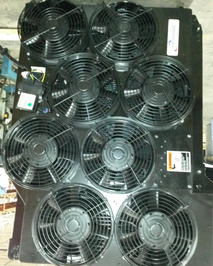
9 Section 2: rmal Operating Conditions rmal system response can be verified by the engine on conditions below and by running the reverse sequence. Engine On 1. CAC fans running slowly 2. Diagnostic bulb illuminates for the first 3 seconds of controller power on then remains off Fan Operation Fan # Layout Charge air cooler (CAC) fans Run at minimum speed when engine starts Radiator (RAD) fans Do not run until coolant temperature reaches 196 F (91 C) te: All CACs fans turn on together at the same speed when commanded and all Radiator fans turn on together at the same speed when commanded. 8/26
 have failed.")
 Press switch momentarily to activate reverse sequence. Fans will run in reverse for about 15 seconds.")

10 Diagnostic Bulb EFAN Troubleshooting Guide Latest Revision: 3/2/2017 Bulb State Meaning Off System is running normally On CAN communication with module has been lost Flashing 1 second on, 1 second off Fans running in reverse sequence, use to check bulb Flashing Long and short duration Indicates which fan(s) have failed. Short flashes indicate fan number, multiple numbers are separated by long pause te: See Troubleshooting Section if CAN Communication is lost or a fan failure has occurred. Reverse Switch (use to check if all fans are working) Press switch momentarily to activate reverse sequence. Fans will run in reverse for about 15 seconds. Diagnostic bulb will flash during this time. This sequence may be aborted by pressing switch again. te: ignition must be on and the fire override (gravity switch on fan door, if installed by OEM, and any other fire override inputs from fire suppression system or IO multiplexer that OEM uses) must be off to run reverse sequence. This may be accomplished by keeping fan door closed or temporarily disconnecting switch. Press to run fans in reverse Press again to abort 9/26

11 Controller LEDs EFAN Troubleshooting Guide Latest Revision: 3/2/2017 Power LED On when controller has power. Controller is powered by vehicle ignition. Fault LED On when a fault has been detected and a data log has been recorded, see Data Log Triggers in Section 4 for more details. If condition is fixed, LED should be off next time the ignition is turned on and no additional service is needed. Section 3: Failsafe Feature Operating Conditions Two failsafe feature operating conditions were put in place to protect the vehicle from an overheat event. These are not normal operating conditions and require further troubleshooting if they occur. 1. CAN Communication Loss Protection Controller will request fans to run at a default speed near full speed. 2. Ignition Failsafe Loss Protection In the event that the controller fails or loses power and the ignition wire to the fans is +24V the fans will run at a default speed near full speed. Section 4: Diagnostic Software The Modine Universal Diagnostic Software (UDS) package has the following functions: Monitor system response in real time Control cooling module manually Download internal data log (RS-232 cable required, Modine PN: 3S ) Supported Devices All RP1210 compliant J1939 data link adapters are supported. Examples include the NexIQ USB-Link (PN: ) and the Cummins INLINE 6 (PN: ). Downloading Diagnostic Software 1. Enter (or click) the following address in your default internet browser: a. Or you can perform the following steps. i. Navigate to ii. Navigate to Products > Transit Bus tab iii. Click on Troubleshooting & Diagnostics on the left side of the screen. iv. Click the Transit Diagnostic Software Link 2. Download and run the setup.exe file. 3. There should now be a Modine UDS program in your Start Menu. 10/26


12 Connecting to Built-in Diagnostic System 1. Make sure the latest version of Modine UDS is installed on computer that will be used for troubleshooting. See previous section. 2. Connect one of the supported data link adapters, outlined above. Drivers must be obtained through the manufacturer s website and installed. 3. Launch Modine UDS and turn on vehicle to power up controller. 4. If this is the first time running Modine UDS with a given datalink adapter: a. Select the Connect RP1210 Adapter button. b. A dialog will appear. First select the Manufacturer driver, then the Device connected to the PC. This list is populated with all drivers installed on the PC. c. Press OK to confirm selection. If connection is unsuccessful, another selection may be attempted. If connection is successful, Modine UDS will remember the selection and automatically connect the last successful device when the program is run again. 5. The bottom of the main window will display connection status along with controller part number and revision level. See image below. 6. The EFAN system status may now be monitored, fans may be manually controlled, and histogram data may be downloaded (if equipped). 11/26

13 Manual Control 1. To enable manual control, check the box next to Manual Control. The fan speed will now reflect the fan speed entered in the boxes below (0-100%). 2. The fans will run at the nearest increment to the entered value. te that this will likely not reflect the exact value entered. If the coolant temperature exceeds 99 C (210 F) or if SPN 986 Percent Fan Request reaches 100, manual mode will be disabled until temperatures decrease. 3. Once the Manual Mode check box is unchecked, fans will resume normal operation. 12/26


14 Interpreting Data 1. Gauges that are grey indicate that there is no J1939 message present. 2. Red fan gauges indicate a fan failure. In this case, fan 3 is failed. 3. Any active DM1 fault messages will be displayed in the message box at the bottom of the screen. 13/26


15 Downloading Data Log 1. If Windows does not recognize the USB diagnostic cable, download the driver here: 2. Open Modine UDS 3. With the controller on, connect the USB diagnostic cable 4. Click the Download Fault Log button near the bottom of the screen. 5. Select the COM port assigned to the cable. 6. When data has been successfully downloaded, a CSV file with the time/date of download will be placed in C:\ModineFaultLogs\ Data Log Triggers The red controller fault LED indicates whether a data log trigger has been activated. Once a trigger has been activated, a snapshot of system status will be recorded on the controller. See Section 5: Troubleshooting - Failure Reported Via CAN or Controller Data log for troubleshooting activities. Trigger High Coolant Temp Under or Over Voltage at Controller Fan Failure High Controller Temp CAN Communication loss Condition J1939 coolant temp is greater than 225 F (107 C) Voltage at controller is < 16 VDC or > 32 VDC One or more fans are not running when they should be Internal controller temperature is greater than 176 F (80 C) CAN/J1939 cable disconnected from controller 14/26
16 Section 5: Troubleshooting Fans Do t Run When They Are Supposed To Possible Cause Fire Override Active (+24 V on Pin C of 6 pin). See Flowchart below for step-by-step diagnosing Tilt switch active (if present). Fire override active from IO multiplexer/fire suppression input. Incorrect PWM output from controller (3% is Off, 40% is min speed, 92% is max speed) Fan(s) not receiving +24V Blown fan fuse or OEM module fuse. Inspect HDP power & ground connection to make sure all wires are seated properly and connector seats completely. Corrosion on fan connector wires. Remedy Replace fire override tilt switch. Consult OEM Troubleshoot CAN Connection. Replace controller. Replace blown fuse. Loss of ground connection Reported fan failure when fan is operating normally Failed fan wiring or fan motor Inspect HDP power & ground connection to make sure all wires are seated properly and connector seats completely. Corrosion on fan connector wires. If no continuity exists on white diagnostic wire between fan and controller. Ensure all connectors are connected correctly. If continuity exists on white diagnostic wire between fan and controller. Apply +24V to power and PWM cavities and ground to ground cavity of individual fan. Wait 15 seconds; fan should begin to spin near full speed. Clean wires and replace terminals, seals and connectors as needed. Replace fan, bad internal power/ground or PWM connection. te: Use UDS real time data monitoring / download data files and OEM reverse feature function as needed for diagnosing. 15/26
17 Fans do not run when they are supposed to EFAN Troubleshooting Guide Latest Revision: 3/2/2017 Check fan fuses and OEM module fuse Check busbar caps Checklist for fans to run +24V on Power (thicker red wire on fan connector) 0V on Ground (black wire on fan connector) +24V on Ignition (thinner red wire on fan connector) +24V for full speed on PWM (yellow wire on fan connector) fans run Some fans run Reverse feature is a good way to test functionality Diagnostic line (white wire) outputs +24V when fan is running Fan ignition wire- if 0V is present on fan ignition cavity and vehicle ignition and controller are both on, fan will operate in normal condition. 0V on fan ignition cavity means ignition failsafe feature in the event of a controller failure, is disabled. Does diagnostic light flash once per second when reverse switch is activated and ignition is on Repair reverse switch. Blue wire. Ensure it supplies 24V to controller when thrown. Also ensure diagnostic light is functioning Is Fire Override activate? Disconnect the fire override switch connector (if equipped) Consult OEM/ troubleshoot fire suppression system or IO multiplexer Failed fans correspond to a fan bank? Is there +24V on fan connector ignition line when vehicle ignition is on? Inspect ignition connection on flat 6-pin connector and ignition busbar Is controller PWM output correct? Next Page Is there +24V on the fan connector power line? Trace power lines back to vehicle connection check fuses and depending on model either: A) ensure HDP connector is properly seated or B) ensure ring terminals are secure and clean Troubleshoot CAN Communication or Replace Controller 16/26
18 Replace fan (bad internal diagnostic wire). Inspect HDP Power & Ground connection. Make sure all wires are seated and connected properly Is there continuity between fan connector diagnostic wire and controller 30-pin connector? Replace terminals and seals (as needed). Do the fans in question run appropriately? Does reported fan failure go away? Use external diagnostic bulb/uds to verify. Replace terminals and seals (as needed). Inspect fan connector. Look for corrosion or loose terminals Fan functionality may be checked by applying system voltage (usually +24V) to fan power wire and PWM wire and ground to fan ground wire. Fan should run near full speed. te: Swapping a fan that runs with a fan that does not run will determine if the failed condition follows the wire harness or the specific fan. Run reverse feature for quick feedback on fan performance. Replace Fan Does fan run? Replace terminals, seals and connectors (as needed). 17/26
19 Fans Run When They Are t Supposed To or Failsafe Features Activated Possible Cause Remedy Loss of fan ground connection Fan not receiving PWM output from controller CAN Communication Loss Controller not receiving +24V (+/- 5 volts) Failed Controller Voltage on fan PWM wire when vehicle ignition is off See Flowchart below for step-by-step diagnosing Inspect HDP power & ground connection to make sure all wires are seated properly and connector seats completely. Corrosion on fan connector wires Check continuity on PWM wire from fan to PWM busbar to controller PWM output cavity and ensure all connectors are properly seated. Check voltages at 5A fuse, Ignition busbar, flat 6-pin (pin A). Verify +24V (+/- 5 volts) volts is across pins H2 (30 pin) and F1 (18 pin) and that 18 and 30 pin connectors are properly seated. Check individual fan connectors and PWM busbars for water penetration or corrosion. Verify greater than 0V exists on fan PWM wire when PWM busbar is removed. Clean wires and replace terminals, seals and connectors. Clean wires and replace terminals, seals, connectors and PWM busbar caps as needed. See CAN Communication Loss troubleshooting section. Replace 5A fuse, ignition busbar, wiring harness or wiring harness section. Clean wires and replace terminals, seals and connectors as needed Replace controller Clean wires and replace terminals seals and connectors. 18/26
20 Replace Controller Fans run when they are not supposed to 24V (+/-5V) between controller pins 30-H2 and 18- F1? Make sure 30 and 18- pin connectors are clean and secure to controller. CAN communication failsafe has occurred Is green controller LED On? Inspect HDP Power & Ground connection. Make sure all wires are seated and connected properly Check ground wire connection. Flat 6-pin connector or ring terminal at OEM chassis ground. Replace 5A fuse, PWM busbar, wiring harness or wiring harness section (as needed). Does an entire bank of fans continue to run? Check 5A controller fuse Is there +24V on each of the components? Disconnect PWM busbars and ignition busbar to determine which individual fan runs by itself. 24V (+/-5V) between controller pins 30-H2 and 18- F1? Make sure 30 and 18- pin connectors are clean and secure to controller. Check voltage at 5A fuse, PWM busar and ignition wire on flat 6-pin connector Do any fans continue to run? Inspect connector on fans that continue to run. Look for water creating a connection between the red ignition or power wires and the yellow PWM wire. Verify greater than 0V exists on PWM line. Verify system operates normally. Reinstall PWM and ignition busbars. Inspect for continuity between PWM busbar and individual fan PWM wire. Make sure all connectors are sealed and connected correctly. Reinstall PWM and ignition busbars. Inspect for continuity between PWM busbar and controller PWM output. Make sure all connectors are sealed and connected correctly. Replace terminals, seals and connectors (as needed). 19/26
21 Failure Reported Via CAN or Controller Data Log The following are the current controller recognized fault codes for the internal data logger: The trigger that created the data log file is located at the bottom row of the log event. te: Controller can store roughly 100 events and they are first in first out. Trigger High Coolant Temp Under or Over Voltage at Controller Fan Failure High Controller Temp CAN Communication loss Condition J1939 coolant temp is greater than 225 F (107 C) Voltage at controller is < 16 VDC or > 32 VDC One or more fans are not running when they should be Internal controller temperature is greater than 176 F (80 C) CAN/J1939 cable disconnected from controller High Coolant Temp Alarm From Engine Possible Cause Remedy See Flowchart below for step-by-step diagnosing Fans do not run when they are supposed to Heat exchanger cores clogged Cooling system leak Fire mode input on (value = 1). Fans in present state show they are not running when supposed to. Fault log reports failed fans (value = 0) See Fans Do t Run When They Are Supposed To troubleshooting section. Clean cores with low pressure, high flow water. Replace damaged component. 20/26
22 High Coolant Temp Alarm From Engine Is Fire Mode Input On/Off value = 1? See Fans Do t Run When They Are Supposed To troubleshooting section for fire override active. See Fans Do t Run When They Are Supposed To troubleshooting section Are the fans operating correctly? Are all Fan # Status columns = 1? See Table 3 in Appendix A for fan failure definition and Fans Do t Run When They Are Supposed To for diagnosing fan failure. Are the heat exchangers damaged/leaking? Replace damaged heat exchangers Clean heat exchangers with low pressure/high flow water 21/26
23 Under or Over Voltage Level at Controller EFAN Troubleshooting Guide Latest Revision: 3/2/2017 Possible Cause Remedy See Flowchart below for step-by-step diagnosing Controller not receiving +24V Inspect ignition connection on 6-pin vehicle connector Loss of ground connection Poor voltage regulator/battery charging system Inspect ground connection on 6-pin vehicle connector. Trace back to bus ground and troubleshoot. Troubleshoot voltage regulator/battery charging system. Consult OEM. te: If the red LED illuminates and the data trigger occurs directly after startup and the system is running normal, allow system to charge, key ignition off and restart to remove red LED light. Under or Over Voltage Level at Controller Inspect IGNITION wire on flat 6-pin vehicle connector Inspect GROUND wire on flat 6-pin vehicle connector Troubleshoot IGNITION source/connection Is there +24V on IGN line? Is there -24V on GROUND line? Troubleshoot GROUND source/connection Troubleshoot voltage regulator/battery charging system. Consult OEM Is the voltage regulator and/or battery charging system operating correctly? Replace terminals and seals on flat 6-pin IGN/GND 22/26
24 Fan Failure When a fan failure is reported in the log file the value for Fan # Status will be 0 in the column corresponding to the fan number. See the Fans Do t Run When They are Supposed To Section for further troubleshooting. High Controller Internal Temperature Possible Cause Remedy See Flowchart below for step-by-step diagnosing Excessive hot air recirculation Controller improperly mounted Inspect cooling system air seals near controller. Inspect mounting of controller and match location listed in Location of Connectors section Consult OEM to eliminate air recirculation. Secure controller in original location. Faulty controller circuitry Replace controller. Reported High Internal Controller Temperature Is there excessive hot air recirculation coming from the engine compartment? Is the controller mounted correctly and in appropriate location? Secure controller correctly Consult OEM to eliminate air recirculation Replace controller 23/26
25 CAN Communication Loss Possible Cause EFAN Troubleshooting Guide Latest Revision: 3/2/2017 Remedy See Flowchart below for step-by-step diagnosing Loose CAN connection at controller External CAN device interference Inspect 3-way Deutsche CAN connector Vehicle ECU Incorrectly configured for E-fan Replace terminals, seals and connectors. Troubleshoot CAN network. Consult OEM Troubleshoot ECU to accept variable speed fan. Consult OEM. Receive CAN Communication Loss error from controller or CAN system Make sure: 3-pin triangle connector is secured Terminating resistor is installed in Y- connector, if equipped Check input statuses using RTMD Test for short circuit: Voltage between +24V (battery voltage) and CAN HIGH and CAN LOW should be between 0 and battery voltage Test with ignition on battery connected Test for open circuit: Resistance on CAN network should be 60 +/- 6 Ohms test with Ignition off and battery disconnected Is CAN communication functioning? Inspect 3-pin triangle CAN connector Check for external devices on CAN network that may disturb controller function Ensure vehicle ECU is properly configured for EFAN system Consult OEM 24/26
26 Appendix A J1939 Messages DM1 Fault Messages Fault Type Source Description J1939 SPN J1939 FMI Fan 1 Inoperable Fan 2 Inoperable Diagnostic Fan 3 Inoperable feedback from fan Fan 4 Inoperable motor indicates Fan Motor Fan 5 Inoperable that fan blades are Fan 6 Inoperable not spinning when Fan 7 Inoperable commanded to Fan 8 Inoperable Fan 1 J1939 Failsafe Mode Fans are running Fan 2 J1939 Failsafe Mode properly but Fan 3 J1939 Failsafe Mode operating Fan 4 J1939 Failsafe Mode conditions form Controller Fan 5 J1939 Failsafe Mode the vehicle CAN Fan 6 J1939 Failsafe Mode bus have been lost Fan 7 J1939 Failsafe Mode Fans are running at Fan 8 J1939 Failsafe Mode failsafe speed Voltage at the Controller system controller Over-Voltage above 32V Voltage at the Controller system controller Under-Voltage below 17V Fire Override input Controller Fire Override Active is active Reverse Active Controller Controller is in reverse sequence J1939 Lamp ne Diagnostic Lamp Flash corresponding to failed fan number Internal Data log trigger? ne Solid ON ne ne ne ne ne ne ne Flash at 1 Hz during sequence Performance Messages Description Pri PGN SA Byte [1-8] Factor Offset Units Rate [ms] PWM % - Fan Bank 1 18 B100 4E % 1000 PWM % - Fan Bank 2 18 B200 4E % 1000 PWM % - Fan Bank 3 18 B300 4E % 1000 tes Minimum fan speed = 40% PWM Maximum fan speed 90% PWM System Identification Description Pri PGN SA Rate Length [bytes] Data Request message 18 EA4E Any N/A 3 18 EA 00 Controller Part Number 18 FEDA 4E On Request 8 Byte 2-6 = Last 5 digits of controller part number Firmware Revision 18 FEDA 4E On Request 8 Byte 7 = Firmware revision 25/26
27 Revision Log EFAN Troubleshooting Guide Latest Revision: 3/2/2017 Revision Description Date CR A Released to production. 3/14/14 B Full redesign to become more useful. 7/3/ C Improve FTP instructions. Add barcode. 10/24/ D Replace FTP instructions with Modine.com. 1/27/ E Cover photo, Title, Section 2 Engine on, Section 4, Section 5, 9/15/ Deleted Appendix A F Deleted Appendix A, Updated Diagnostic Software 1/13/ G Updated title page, added DM1 and J1939 messages 3/2/ H Removed Common Service parts Appendix 3/23/ /26
ITCEMS950 Idle Timer Controller - Engine Monitor Shutdown Isuzu NPR 6.0L Gasoline Engine
 Introduction An ISO 9001:2008 Registered Company ITCEMS950 Idle Timer Controller - Engine Monitor Shutdown 2014-2016 Isuzu NPR 6.0L Gasoline Engine Contact InterMotive for additional vehicle applications
Spray Height Controller
 Spray Height Controller UC5 SERVICE MANUAL 2012 Printed in Canada Copyright 2012 by NORAC Systems International Inc. Reorder P/N: UC5 SERVICE MANUAL 2012 Rev B NOTICE: NORAC Systems International Inc.
Additions, Revisions, or Updates
 1 06 10-16 SUBJECT SPN 111 (CPC) (GHG17) and SPN 111 (CPC) (EPA07;EPA10;GHG14) DATE June 2016 Additions, Revisions, or Updates Publication Number / Title Platform Section Title Change DDC-SVC-MAN-0191
SST-3 Start-Stop-Throttle
 SST-3 Start-Stop-Throttle Installation & Operation Guide Revision 1.1 Internet: www.wiredrite.com E-mail: info@wiredrite.com Page 1 CONTENTS Introduction 2 Hardware Mounting 2 Connections 2 Operation &
Quick Start Guide TK3/TK4 Thermal System Assembly and Fan Shroud Assembly
 Quick Start Guide TK3/TK4 Thermal System Assembly and Fan Shroud Assembly This Quick Start Manual is effective for Consumer installations of the part numbers listed in Table 1 and Table 2. OEM installers
PF3100 TROUBLESHOOTING SOLUTIONS TO COMMON PROBLEMS. v1.1 Revised Nov 29, 2016
 PF3100 TROUBLESHOOTING SOLUTIONS TO COMMON PROBLEMS v1.1 Revised Table of Contents 1 Common Alarms and Warnings... 1 2 Common Issues... 6 2.1 Communication problems... 6 2.1.1 Controller communication
Cover. L5v2 Plug-In Conversion Module(PCM) Diagnostic Trouble Codes
 Diagnostic Trouble Codes") Cover L5v2 Plug-In Conversion Module(PCM) Diagnostic Trouble Codes Copyright 2009 A123 Systems, Inc. All rights reserved DOCUMENT NOTICE: The information contained in this manual is the property of A123
Cover L5v2 Plug-In Conversion Module(PCM) Diagnostic Trouble Codes Copyright 2009 A123 Systems, Inc. All rights reserved DOCUMENT NOTICE: The information contained in this manual is the property of A123
Idle Timer Controller - ITC515-A Ford Transit Contact InterMotive for additional vehicle applications
 An ISO 9001:2008 Registered Company Idle Timer Controller - ITC515-A 2015-2018 Ford Transit Contact InterMotive for additional vehicle applications Overview The ITC515-A system will shut off gas or diesel
Advanced User Manual
 Advanced User Manual Banks SpeedBrake For use with Palm Tungsten E2 2004-2005 Chevy/GMC 6.6L (LLY) Turbo-Diesel Pickup THIS MANUAL IS FOR USE WITH KITS 55419 & 55421 Gale Banks Engineering 546 Duggan Avenue
DTC P0A04 - Open Wiring Fault
 DTC P0A04 - Open Wiring Fault Orion Product Orion BMS [Original] (24-180 Cell) Orion BMS 2 (24-180 Cell) Orion JR (16 Cell) Fault Supported YES YES YES FAULT DESCRIPTION This fault is a serious code that
Quick Setup Guide for IntelliAg Model YP Air Pro
 STEP 1: Pre-Programming Preparation: The Quick Guide assumes the Virtual Terminal, Master Switch, Working Set Master, Working Set Member, and all sensors have been connected and properly installed. Reference
Quick Setup Guide for IntelliAg Model YP40 20 Air Pro
 STEP 1: Pre-Programming Preparation: The Quick Guide assumes the Virtual Terminal, Master Switch, Working Set Master, Working Set Member, and all sensors have been connected and properly installed. Reference
Getting Started HONDA
 Getting Started HONDA Product Introduction Congratulations on the purchase of your new AccessPORT handheld programmer. This quick start guide explains how to install the AP on your vehicle. Refer to the
Subject Underhood G System Error Codes and Symptoms System or Parts affected
 System or Parts affected Index Underhood70G (V90Gxxx) System or Parts affected... 1 Overview... 1 Identifying your System... 1 Retrieving Logged Error Messages... 1 Error Messages... 3 Error Message Table...
Fault Code 34 - Weak Battery Voltage Supply
 Fault Code 34 - Weak Battery Voltage Supply Fault Isolation Procedures TRTS0930 Fault Code 34 - Weak Battery Voltage Supply J1587: MID 130 PID 168 FMI 14 J1939: SA 3 SPN 168 FMI 14 Overview This fault
INDEX. 1.Safety Precautions and Warnings...3
 INDEX 1.Safety Precautions and Warnings...3 2. General Information...5 2.1 On-Board Diagnostics (OBD) II... 5 2.2 Diagnostic Trouble Codes (DTCs)... 6 2.3 Location of the Data Link Connector (DLC)...7
PDC PROPELLER DE-ICE CONTROLLER
 PDC PROPELLER DE-ICE CONTROLLER OPERATIONAL & INSTALL MANUAL Updated: 14 October 2016 Copyright 2016 by VR Avionics Inc. All rights reserved. This User and Installation Guide and the information contained
SECTION 5 DIAGNOSTIC TROUBLE CODES (DTC)
") 5 1. DTC MEMORY SECTION 5 Diagnostic Trouble Codes (DTCs) are logged in a list in TCM memory. The DTCs contained in the list have information recorded as shown in Table 5 1 (DTC example). The TCM is capable
5 1. DTC MEMORY SECTION 5 Diagnostic Trouble Codes (DTCs) are logged in a list in TCM memory. The DTCs contained in the list have information recorded as shown in Table 5 1 (DTC example). The TCM is capable
Additions, Revisions, or Updates
 1 06 13-16 SUBJECT DATE SPN 1590 (CPC) (GHG17) June 2016 Additions, Revisions, or Updates Publication Number / Title Platform Section Title Change DDC-SVC-MAN-0193 GHG17 Medium Duty SPN 1590/FMI 9 - GHG17
Table of Contents 1. INTRODUCTION GENERAL INFORMATION-ABOUT OBDII/EOBD PRODUCT DESCRIPTIONS OPERATIONS...11
 Table of Contents 1. INTRODUCTION...1 2. GENERAL INFORMATION-ABOUT OBDII/EOBD...1 2.1 ON-BOARD DIAGNOSTICS (OBD) II...1 2.2 DIAGNOSTIC TROUBLE CODES (DTCS)...2 2.3 LOCATION OF THE DATA LINK CONNECTOR (DLC)...3
Additions, Revisions, or Updates
 03 57-17 1 03 57-17 SUBJECT DATE SPN 625 (CPC) (GHG17) March 2017 Additions, Revisions, or Updates Publication Number / Title Platform Section Title Change DDC-SVC-MAN-0191 GHG17 DD Platform SPN 625/FMI
Quick Setup Guide for IntelliAg Model 3PYP 12 Row Single Row Air Pro
 STEP 1: Pre-Programming Preparation: Power on vehicle via ignition switch to activate Virtual Terminal (VT). Main menu will display pre-programmed default settings. If errors are detected (e.g., failed
SECOND GENERATION Use this guide with unit serial number prefix beginning with BWF using Terra Power separator.
 Technical Information and Diagnostic Guide for SECOND GENERATION Use this guide with unit serial number prefix beginning with BWF using Terra Power separator. This guide will assist you in becoming more
DESCRIPTION & OPERATION
 DESCRIPTION & OPERATION 1998-99 SUSPENSION Electronic - Real Time Damping - Corvette The Real Time Damping (RTD) system automatically controls vehicle ride by independently controlling a damper solenoid
Issue 2.0 December EPAS Midi User Manual EPAS35
 Issue 2.0 December 2017 EPAS Midi EPAS35 CONTENTS 1 Introduction 4 1.1 What is EPAS Desktop Pro? 4 1.2 About This Manual 4 1.3 Typographical Conventions 5 1.4 Getting Technical Support 5 2 Getting Started
Overview of operation modes
 Overview of operation modes There are three main operation modes available. Any of the modes can be selected at any time. The three main modes are: manual, automatic and mappable modes 1 to 4. The MapDCCD
GTWY505 Fast Idle, Shift Interlock, I/O Ford E-Series
 An ISO 9001:2008 Registered Company GTWY505 Fast Idle, Shift Interlock, I/O 2009-2018 Ford E-Series Introduction The Gateway 505 is a wheelchair lift safety interlock which will only work with the ignition
GTWY605 Fast Idle, Shift Interlock, I/O Chevy 610 Van - 6.0L and 6.6L Engines Contact InterMotive for additional vehicle applications.
 An ISO 9001:2008 Registered Company GTWY605 Fast Idle, Shift Interlock, I/O 2009-2017 Chevy 610 Van - 6.0L and 6.6L Engines Contact InterMotive for additional vehicle applications. Introduction The Gateway
Troubleshooting Guide
 Bendix VORAD VS-400 Radar System Troubleshooting Guide Bendix VORAD Collision Warning System Bendix SmartCruise Adaptive Cruise Control Bendix BlindSpotter Side Object Detection BW2771 (Formerly VOTS0100)
Product Guide: Series III Pump Control Board Set (RoHS)
") revised 04/08/10 Description: The Series III Pump Control Board Set provides motor drive and pump control for a wide assortment of pumps from Scientific Systems, Inc. The assembly consists of two circuit
revised 04/08/10 Description: The Series III Pump Control Board Set provides motor drive and pump control for a wide assortment of pumps from Scientific Systems, Inc. The assembly consists of two circuit
Additions, Revisions, or Updates
 1 01 11-16 SUBJECT DATE SPN 647 (MCM)(EPA07-EPA10-GHG14) January 2016 Additions, Revisions, or Updates Publication Number / Title Platform Section Title Change DDC-SVC-MAN-0084 DDC-SVC-MAN-S084 DD Platform
SECTION 12M - SUPPLEMENTAL RESTRAINT SYSTEM (VERSIONS 8.0 AND 8.1)
") SECTION 12M - SUPPLEMENTAL RESTRAINT SYSTEM (VERSIONS 8.0 AND 8.1) IMPORTANT Before performing any Service Operation or other procedure described in this Section, refer to Section 00 CAUTIONS AND NOTES
SECTION 12M - SUPPLEMENTAL RESTRAINT SYSTEM (VERSIONS 8.0 AND 8.1) IMPORTANT Before performing any Service Operation or other procedure described in this Section, refer to Section 00 CAUTIONS AND NOTES
Idle Timer Controller - A-ITC520-A Ford E Series Ford F250 - F Ford F250 - F550 (*B-ITC520-A) F650/F750
 F650/F750") An ISO 9001:2008 Registered Company Idle Timer Controller - A-ITC520-A 2009-2018 Ford E Series 2008-2016 Ford F250 - F550 2017-2018 Ford F250 - F550 (*B-ITC520-A) 2016-2018 F650/F750 *Uses the Ford 24-Pin
An ISO 9001:2008 Registered Company Idle Timer Controller - A-ITC520-A 2009-2018 Ford E Series 2008-2016 Ford F250 - F550 2017-2018 Ford F250 - F550 (*B-ITC520-A) 2016-2018 F650/F750 *Uses the Ford 24-Pin
Cannondale Diagnostic Tool Manual
 Cannondale Diagnostic Tool Manual For vehicles (ATV & Motorcycles) equipped with the MC1000 Engine Management System Software CD P/N 971-5001983 Data Cable P/N 971-5001984 POTENTIAL HAZARD Running the
Kelly KDC Series/PM Motor Controller User s Manual
 Kelly KDC Series/PM Motor Controller User s Manual KDC48600 KDC48601 KDC48602 KDC48603 KDC72600 KDC72601 KDC72602 KDC72603 KDC72800 KDC72801 KDC72802 KDC72803 KDC12602 KDC12603 Rev.3.3 May 2011 Contents
System III Wiring Information 54-12
 System III Wiring Information 54-12 System Operation General Information Initial Power On Description of Revisions: This service bulletin is updated and replaces the version dated September 2002. This
INSTALL GUIDE OEM-CH(RS)-CH8-[FLRSCH10]-EN
![INSTALL GUIDE OEM-CH(RS)-CH8-[FLRSCH10]-EN](/thumbs/95/124149590.jpg "INSTALL GUIDE OEM-CH(RS)-CH8-[FLRSCH10]-EN") INSTALL GUIDE DOCUMENT NUMBER 58012 REVISION DATE 20190114 FIRMWARE OEM-CH(RS)-CH8-[FLRSCH10] HARDWARE FLRSCH10 ESSORIES FLPROG (REQUIRED) TERMS OF USE: Automotive Data Solutions Inc. ( ADS ) products
INSTALL GUIDE DOCUMENT NUMBER 58012 REVISION DATE 20190114 FIRMWARE OEM-CH(RS)-CH8-[FLRSCH10] HARDWARE FLRSCH10 ESSORIES FLPROG (REQUIRED) TERMS OF USE: Automotive Data Solutions Inc. ( ADS ) products
Rev Rev. Additions, Revisions, or Updates
 1 4 89-12Rev SUBJECT DATE SPN 5927/FMI 2 and 7 - GHG14 April 2012 Additions, Revisions, or Updates Publication Number / Title Platform Section Title Change SPN 5927/FMI 2 - DDC-SVC-MAN-0084 DD Platform
Additions, Revisions, or Updates
 1 01 06-17 SUBJECT DATE SPN 520296 (MCM) (GHG14) and SPN 520296 (MCM) (GHG17) January 2017 Additions, Revisions, or Updates Publication Number / Title Platform Section Title Change DDC-SVC-MAN-0084 DDC-SVC-MAN-0191
BigStuff3 - GEN3. 1st Gear Spark Retard with Spark Retard Traction Control System (SR 2 ) Rev
 Rev") BigStuff3 - GEN3 1st Gear Spark Retard with Spark Retard Traction Control System (SR 2 ) 12-09 System Description 1st Gear Spark Retard with Spark Retard Traction Control System (SR 2 ) - SR 2 uses two
BigStuff3 - GEN3 1st Gear Spark Retard with Spark Retard Traction Control System (SR 2 ) 12-09 System Description 1st Gear Spark Retard with Spark Retard Traction Control System (SR 2 ) - SR 2 uses two
SBW and SBW2 Troubleshooting Guide AES-286 ECN REV REVISION RECORD DATE ENGINEER
 Industrial Group - Arens Controls Industrial Division 3602 N Kennicott Ave Arlington Heights, IL 60004, USA T: +1.847.844.4700 www.cw-industrial.com SBW and SBW2 Troubleshooting Guide AES-286 ECN REV REVISION
CLA-VAL e-drive-34. User Manual. Motorised Pilots. CLA-VAL Europe LIN072UE - 04/16
 User Manual CLA-VAL Europe www.cla-val.ch cla-val@cla-val.ch 1 - LIN072UE - 04/16 Table of Contents 1 Introduction... 3 1.1 Precautions Before Starting... 3 1.2 Troubleshooting... 3 1.3 General Disclaimer...
An ISO 9001:2008 Registered Company
 An ISO 9001:2008 Registered Company Introduction Engine Monitor System 2009-2018 Ford E Series (EMS501-D) 2008-2010 Ford F250-550 6.2L, 6.8L (EMS506-D) 2011-2016 Ford F250-550 6.2L, 6.8L (EMS507-D) 2017
CONTROLLER DIAGNOSTIC GUIDE
 Proprietary tice: This document contains proprietary information which not to be reproduced, transferred, to other documents, disclosed to others, used for manufacturing or any other purpose without the
INSTALL GUIDE DIR-CH(RS)-CH8-[FLRSCH10]-EN
![INSTALL GUIDE DIR-CH(RS)-CH8-[FLRSCH10]-EN](/thumbs/85/92438523.jpg "INSTALL GUIDE DIR-CH(RS)-CH8-[FLRSCH10]-EN") INSTALL GUIDE DOCUMENT NUMBER 870 REVISION DATE 080 FIRMWARE DIR-CH(RS)-CH8-[FLRSCH0] HARDWARE FLRSCH0 ESSORIES FLPROG (REQUIRED) DIRECTED XL-0 RF-KIT & ADS-HRN(RS)-XL0 (OPTIONAL) DIRECTED SMART & ADS-HRN(RS)-SM0
INSTALL GUIDE DOCUMENT NUMBER 870 REVISION DATE 080 FIRMWARE DIR-CH(RS)-CH8-[FLRSCH0] HARDWARE FLRSCH0 ESSORIES FLPROG (REQUIRED) DIRECTED XL-0 RF-KIT & ADS-HRN(RS)-XL0 (OPTIONAL) DIRECTED SMART & ADS-HRN(RS)-SM0
NUMBER: S.M. REF.: Listed in Table ENGINE: EPA07 MBE 4000 DATE: April 2009
 NUMBER: 4 11 09 S.M. REF.: Listed in Table ENGINE: EPA07 MBE 4000 DATE: April 2009 SUBJECT: SPN 2631 ADDITIONS, REVISIONS, OR UPDATES Publication Number Platform Section Title Change Page Number(s) DDC-SVC-MAN-0010
SIDE ROLL SENSOR TROUBLESHOOTING GUIDE
 SIDE ROLL SENSOR TROUBLESHOOTING GUIDE WARNING Service the roll sensor(s) only if you are an authorized technician. The roll sensor triggers airbags and seat restraints. Accidental deployment could cause
Additions, Revisions, or Updates
 1 01 29-14 SUBJECT DATE SPN 3511/FMI 3 and 4 - GHG14 January 2014 Additions, Revisions, or Updates Publication Number / Title Platform Section Title Change SPN 3511/FMI 3 - DDC-SVC-MAN-0084 GHG14 DD Platform
ROCKLEA TRUCK ELECTRICAL. Sleeper Air NXT. Owner s Manual. Revision th March 2013
 ROCKLEA TRUCK ELECTRICAL Sleeper Air NT Owner s Manual Revision 230 24 th March 2013 Rocklea Truck Electrical Rocklea Truck Electrical is Brisbane's premier truck lighting and custom accessory manufacturer
An ISO 9001:2008 Registered Company
 Introduction An ISO 9001:2008 Registered Company GTWY506 Fast Idle, Shift Interlock, I/O 2011-2016 Ford F250-F550 2017 Ford F250-F550 (Uses the Ford 24-Pin Data Link Harness) 2016-2017 Ford F650/750* *Transmission
GRD502-B Flow Chart 02/05/09
 PINPOINT TEST A: NO PROVE OUT OF ANY LEDs prove out (all LED's light up) of the LED's when module power is applied or module "wakes up", indicates that: - the Guardian module does not have power. - the
NUMBER: S.M. REF.: Listed in Table ENGINE: EPA07 MBE 4000 DATE: September 2009
 NUMBER: 9 3 09 S.M. REF.: Listed in Table ENGINE: EPA07 MBE 4000 DATE: September 2009 SUBJECT: TURBOCHARGER WASTEGATE ADDITIONS, REVISIONS, OR UPDATES Publication Number Platform Section Title Change Page
Planting. Press to Highlight Configuration. Gauge Wheel Load Alarm. Value must be entered for your specific planter and parallel arm combination
 To create a configuration, make the following button presses to start the Configuration Wizard and then follow the instructions given on the display. Planting Start of Configuration Wizard Enter Settings
DESCRIPTION & OPERATION
 ANTI-THEFT SYSTEM 1998 ACCESSORIES & EQUIPMENT General Motors Corp. - Anti-Theft System DESCRIPTION & OPERATION WARNING: Deactivate air bag system before performing any service operation. See AIR BAG RESTRAINT
Additions, Revisions, or Updates
 1 6 05-13 SUBJECT DATE SPN 625/FMI 9 EPA10 - GHG14 June 2013 Additions, Revisions, or Updates Publication Number / Title Platform Section Title Change DDC-SVC-MAN-0084 EPA10/ GHG14 DD Platform SPN 625/FMI
INSTALL GUIDE AKX-IDS(RS)-BZ1B-[ADS-BZ1]-EN
![INSTALL GUIDE AKX-IDS(RS)-BZ1B-[ADS-BZ1]-EN](/thumbs/77/75040905.jpg "INSTALL GUIDE AKX-IDS(RS)-BZ1B-[ADS-BZ1]-EN") INSTALL GUIDE DOCUMENT NUMBER 25893 REVISION DATE 2627 FIRMWARE AKX-IDS(RS)-BZ1B-[ADS-BZ1] HARDWARE ADS-BZ1 ESSORIES ADS-USB (REQUIRED) COMPATIBLE RF-KIT (OPTIONAL) DIRECTED SMART & ADS-HRN(RS)-SM (OPTIONAL)
INSTALL GUIDE DOCUMENT NUMBER 25893 REVISION DATE 2627 FIRMWARE AKX-IDS(RS)-BZ1B-[ADS-BZ1] HARDWARE ADS-BZ1 ESSORIES ADS-USB (REQUIRED) COMPATIBLE RF-KIT (OPTIONAL) DIRECTED SMART & ADS-HRN(RS)-SM (OPTIONAL)
Subaru L Turbo
 Subaru 02-05 2.0L Turbo Getting Started Product Introduction Congratulations on the purchase of the new AccessPORT handheld programmer. The AccessPORT can: Reprogram the factory engine control unit (ECU)
ISC, QSC8.3, and ISL (FIS )
") Fault Information System... 1 FIS Usage Recommendations... 2 FIS Usage Recommendations... 2 Diagnostic Methods... 9 Troubleshooting Fault Codes... 9 Information Fault Codes... 3 (fc211) Fault Code 211...
Fault Information System... 1 FIS Usage Recommendations... 2 FIS Usage Recommendations... 2 Diagnostic Methods... 9 Troubleshooting Fault Codes... 9 Information Fault Codes... 3 (fc211) Fault Code 211...
CORNERING LIGHTING MODULE CLM02-CAN INSTALLATION MANUAL
 CORNERING LIGHTING MODULE CLM02-CAN INSTALLATION MANUAL QUASAR ELECTRONICS ul. Cieślewskich 2K 03-07 Warszawa tel. (22) 427-3-4..44 http://www.quasarelectronics.pl e-mail: biuro@quasarelectronics.pl OPERATION
Quick Start Guide Polaris Snow Sled, and ATV
 Thank you for purchasing CANDooPro! Please read the following information before using the system for the first time. If you have any questions about the use of the system, please contact us at Sales@CANDooPro.com,
Modulating Furnace Information. Warning on Meter Setting - Read First!
 Modulating Furnace Information Pressure Transducer Pressure DC Volts 0.00" 0.25 0.20" 0.63 0.25" 0.72 0.30" 0.82 0.35" 0.91 0.40" 1.00 0.45" 1.09 0.50" 1.19 0.55" 1.28 0.60" 1.38 0.65" 1.47 0.70" 1.56
GTWY515, GTWY516* Fast Idle, Shift Interlock, I/O Ford Transit Introduction
 An ISO 9001:2015 Registered Company GTWY515, GTWY516* Fast Idle, Shift Interlock, I/O 2015-2019 Ford Transit Introduction The Gateway 515 and 516 are wheelchair lift safety interlocks which allows lift
INSTALL GUIDE IDL-IDS(RS)-BZ2B-[ADS-BZ2]-EN
![INSTALL GUIDE IDL-IDS(RS)-BZ2B-[ADS-BZ2]-EN](/thumbs/94/120297305.jpg "INSTALL GUIDE IDL-IDS(RS)-BZ2B-[ADS-BZ2]-EN") INSTALL GUIDE DOCUMENT NUMBER 450 REVISION DATE FIRMWARE IDL-IDS(RS)-BZB-[ADS-BZ] HARDWARE ADS-BZ ESSORIES ADS-USB (REQUIRED) COMPATIBLE RF-KIT (OPTIONAL) DIRECTED SMART & ADS-HRN(RS)-SM0 (OPTIONAL) ADS-TOOLS-MB0
INSTALL GUIDE DOCUMENT NUMBER 450 REVISION DATE FIRMWARE IDL-IDS(RS)-BZB-[ADS-BZ] HARDWARE ADS-BZ ESSORIES ADS-USB (REQUIRED) COMPATIBLE RF-KIT (OPTIONAL) DIRECTED SMART & ADS-HRN(RS)-SM0 (OPTIONAL) ADS-TOOLS-MB0
Feature Description. Version History
 TA2 Malfunction Indicator Lamp (MIL) and Engine Protection Document Number: FD-0007 Author: J. Goodloe Version: 03 Publish Date: 2016-03-18 Feature Description Version History Version Date Modified Sections
DASH RETRIEVED FAULT CODES C ONVENTIONAL FS65 SAF T LINER C2, C2E H YBRID SAF T LINER HDX, HD, ER SAF T LINER EF, EFX A LL Y EARS
 DASH RETRIEVED FAULT CODES C ONVENTIONAL FS65 SAF T LINER C2, C2E H YBRID SAF T LINER HD, HD, ER SAF T LINER EF, EF A LL Y EARS PAGE INTENTIONALLY LEFT BLANK TABLE OF CONTENTS EARLY PRODUCTS: J1587/J1708
Idle Timer Controller - ITC Freightliner MT45 Contact InterMotive for additional vehicle applications
 An ISO 9001:2008 Registered Company System Operation Idle Timer Controller - ITC805 2013-2018 Freightliner MT45 Contact InterMotive for additional vehicle applications The ITC805 system shuts down idling
NUMBER: S.M. REF.: Listed in Table ENGINE: EPA07 Series 60 DATE: April 2009
 NUMBER: 4 7 09 S.M. REF.: Listed in Table ENGINE: EPA07 Series 60 DATE: April 2009 SUBJECT: SPN 27 ADDITIONS, REVISIONS, OR UPDATES Publication Number Platform Section Title Change Page Number(s) DDC-SVC-MAN-0009
THE witech SOFTWARE LEVEL MUST BE AT RELEASE **15.04** OR HIGHER TO PERFORM THIS PROCEDURE.
 2014 RAM 3500 HD 6.7L Eng Big Horn FLASH: 6.7L DIAGNOSTIC AND SYSTEM IMPROVEMENTS TECHNICAL SERVICE BULLETIN Reference Number(s): 18-045-15, Date of Issue: May 20, 2015 CHRYSLER: 2014 Ram 2500 Pick Up
SECTION Instrument Cluster and Panel Illumination
 413-00-i Instrument Cluster and Panel Illumination 413-00-i SECTION 413-00 Instrument Cluster and Panel Illumination CONTENTS PAGE DIAGNOSIS AND TESTING Instrument Cluster and Panel Illumination... 413-00-2
Service Manual Model S400 and S500 Smart Stand
 Service Manual Model S400 and S500 Smart Stand Form #1-145 Rev. 10/3/13 Table of Contents Parts Breakdown 3 Monthly Maintenance Checklist 7 Smart Stand Operating Instructions 9 Scale Calibration 10 Advanced
Mitsubishi. VFD Manuals
 Mitsubishi VFD Manuals Mitsubishi D700 VFD Installation Mitsubishi FR-D700 VFD User Manual Mitsubishi D700 Parallel Braking Resistors VFD Wiring Diagram - Apollo Mitsubishi VFD to Interpreter Mitsubishi
VFD. Variable Frequency Drive
 VFD Variable Frequency Drive Mitsubishi Mitsubishi D700 VFD Installation Mitsubishi FR-D700 VFD User Manual Mitsubishi D700 Parallel Braking Resistors VFD Wiring Diagram - Apollo Mitsubishi VFD to Interpreter
System Overview Quick-Start Guide Mini-Hybrid Cooling System for Refuse Applications
 System Overview Quick-Start Guide Mini-Hybrid Cooling System for Refuse Applications Prepared for Serial number Rev Rev By Date Description of Change Approved By A JRB 7/26/2016 New Release ECN4325 9970039096_Rev
AWARE TM VEHICLE INTELLIGENCE INSTALLATION MANUAL
 AWARE TM VEHICLE INTELLIGENCE INSTALLATION MANUAL FOR INTERNATIONAL TRUCKS CXT, RXT, MXT, 3200, 4100, 4200, 4300, 4400, 7300, 7400, 7500, 7600, 7700, 8500 and 8600 For Models Built After 2007 MODULES ARE
Steering Angle Sensor (SAS) Replacement on Vehicles Equipped with Electronic Stability Control (ESC)
 Replacement on Vehicles Equipped with Electronic Stability Control (ESC)") Revised 09-18 Technical Bulletin Steering Angle Sensor (SAS) Replacement on Vehicles Equipped with Electronic Stability Control (ESC) Revised 1 Technical 09-18 Bulletin Hazard Alert Messages Read and observe
Revised 09-18 Technical Bulletin Steering Angle Sensor (SAS) Replacement on Vehicles Equipped with Electronic Stability Control (ESC) Revised 1 Technical 09-18 Bulletin Hazard Alert Messages Read and observe
EPAS Desktop Pro Software User Manual
 Software User Manual Issue 1.10 Contents 1 Introduction 4 1.1 What is EPAS Desktop Pro? 4 1.2 About This Manual 4 1.3 Typographical Conventions 5 1.4 Getting Technical Support 5 2 Getting Started 6 2.1
Additions, Revisions, or Updates
 1 10 09-14 SUBJECT DATE SPN 5016 (ACM) (GHG14) October 2014 Additions, Revisions, or Updates Publication Number / Title Platform Section Title Change SPN 5016/FMI 3 - DDC-SVC-MAN-0084 GHG14 DD Platform
Kelly HSR Series Motor Controller with Regen User s Manual V 3.3. Kelly HSR Opto-Isolated Series Motor Controller with Regen.
 Kelly HSR Opto-Isolated Series Motor Controller with Regen User s Manual HSR72601 HSR72801 HSR12401 HSR12601 HSR12901 HSR14301 HSR14501 HSR14701 Rev.3.3 Dec. 2011 Contents Chapter 1 Introduction... 2 1.1
Application Engineering Europe
 Date of last update: Feb-12 Ref: D7.8.4/0112-0212/E Application Engineering Europe CORESENSE DIAGNOSTICS FOR STREAM REFRIGERATION COMPRESSORS 1/17 1 Introduction CoreSense is an ingredient brand name for
Intelli-Feed Controller User s Manual Intelli-Feed Digital Tachometer and Hourmeter
 Intelli-Feed Controller User s Manual Intelli-Feed Digital Tachometer and Hourmeter Part #: 9047 Table of Contents: Table of Contents 2 Intelli-Feed TM User Interface 3 Equipment Diagnostic Indicators
Installation Instructions & Users Manual
 Installation Instructions & Users Manual UTILITY/ BUILDING INPUT 120 VAC ( OPTION) 15-20A N L CONTROL BOARD G SECURITY LIGHTING POWER SUPPLY (OPTION) CHARGER- POWER SUPPLY ASSBY XFMR (OPTION) CBM MODEL
Indian Speedometer and Body Control Module Service Tool Users Guide
 Indian Speedometer and Body Control Module Service Tool Users Guide Installing speedometer software to your computer 1. Go to the Indian Motorcycle Website: WWW. Indianmotorcycle.com 2. Log in to Service
Wiring diagrams on page 29 are for reference only. For detailed vehicle wiring refer to Navistar documents.
 1 10/2014 REV 7 !!Attention!! Before performing diagnostics: Wiring diagrams on page 29 are for reference only. For detailed vehicle wiring refer to Navistar documents. Check for Fault Codes using the
INSTALL GUIDE COM-HA(RS)-HA6P-[FT-HA6-DC]-EN
![INSTALL GUIDE COM-HA(RS)-HA6P-[FT-HA6-DC]-EN](/thumbs/91/107082835.jpg "INSTALL GUIDE COM-HA(RS)-HA6P-[FT-HA6-DC]-EN") INSTALL GUIDE DOCUMENT NUMBER 49378 REVISION DATE 20180412 FIRMWARE COM-HA(RS)-HA6P-[FT-HA6-DC] HARDWARE FT-HA6-DC ACCESSORIES ADS-USB (REQUIRED) COMPATIBLE RF-KIT (OPTIONAL) DRONE MOBILE DR-2000 (OPTIONAL)
INSTALL GUIDE DOCUMENT NUMBER 49378 REVISION DATE 20180412 FIRMWARE COM-HA(RS)-HA6P-[FT-HA6-DC] HARDWARE FT-HA6-DC ACCESSORIES ADS-USB (REQUIRED) COMPATIBLE RF-KIT (OPTIONAL) DRONE MOBILE DR-2000 (OPTIONAL)
THE witech SOFTWARE LEVEL MUST BE AT RELEASE OR HIGHER TO PERFORM THIS PROCEDURE.
 NUMBER: 18-006-12 GROUP: Vehicle Performance DATE: February 04, 2012 This bulletin is supplied as technical information only and is not an authorization for repair. No part of this publication may be reproduced,
NUMBER: S.M. REF.: Listed in Table ENGINE: EPA07 MBE 4000 DATE: May 2013 SUBJECT: SPN 2631/FMI 2 ADDITIONS, REVISIONS, OR UPDATES
 NUMBER: 5 26 13 S.M. REF.: Listed in Table ENGINE: EPA07 MBE 4000 DATE: May 2013 SUBJECT: SPN 2631/FMI 2 ADDITIONS, REVISIONS, OR UPDATES Publication Number Platform Section Title Change DDC-SVC-MAN-0010
Service Manual Model S800 Smart Stand
 Service Manual Model S800 Smart Stand Form #1-146 Rev. 10/3/13 Table of Contents Parts Breakdown 3 Monthly Maintenance Checklist 7 Smart Stand Operating Instructions 9 Scale Calibration 10 Advanced Smart
MICROPROCESSOR BASED CONTROLLER
 MICROPROCESSOR BASED CONTROLLER Electronic Controller for Bus HVAC Front Box Units FrontAIRE II SERVICE MANUAL TK 53337-3-MM (Rev. 0, 09/06) 2006 THERMO KING Table of contents 1. General Information...
Idle Timer Controller - A-ITC620-A Chevrolet Express/GMC Savana
 Introduction An ISO 9001:2015 Registered Company Idle Timer Controller - A-ITC620-A1 2009-2019 Chevrolet Express/GMC Savana Contact InterMotive for additional vehicle applications The A-ITC620-A1 is an
Vehicle Improvement Products
 SmartWheel LIN Steering Wheel Troubleshooting Guide For use with: Steering Wheels V44 Series, Controller SM213 Published: 25 February 2011 Revised: 25 February 2011 The following guide is for use with
SECTION Multifunction Electronic Modules
 419-10-i Multifunction Electronic Modules 419-10-i SECTION 419-10 Multifunction Electronic Modules CONTENTS PAGE DIAGNOSIS AND TESTING Smart Junction Box (SJB)... 419-10-2 Principles of Operation... 419-10-2
GSC300. Auto Start Engine Controller. Installation and User Manual for the GSC300 Auto Start Engine Controller. Full Version
 GSC300 Auto Start Engine Controller Installation and User Manual for the GSC300 Auto Start Engine Controller Full Version File: GSC300rev2.4.doc Dec. 08, 2005 2 Thank You For Purchasing This DynaGen Product
Enova Hybrid Systems
 Enova Hybrid Systems Study Guide Study Guide Enova Hybrid Systems EDUCATION 2009 Navistar, Inc. 4201 Winfield Road, Warrenville, IL 60555 All rights reserved. No part of this publication may be duplicated
SERVICE MANUAL. Kysor Instrumentation Troubleshooting Guide
 Kysor Instrumentation Troubleshooting Guide Troubleshooting Emergency One Commercial System The Medallion II instrumentation system is a Microprocessor based system utilizing both Sensor and Data bus information
If you ever have any questions, please contact our support team: cobbtuning.com/support
 P. 1 HOW IT WORKS Welcome to the quick start guide for your new Accessport! This guide will give you a brief overview of how to use your device. Please visit cobbtuning.com/apsupport for the complete instruction
FT-10 Network Digital I/O Module Kits and
 Instruction Sheet 10-2004 FT-10 Network Digital I/O Module Kits 541 0771 and 541 0772 PURPOSE OF KIT The Digital I/O Module (DIM) makes provisions for a group of relay contact outputs and discrete inputs
INSTALLATION INSTRUCTIONS. Revision 3.1.1
 INSTALLATION INSTRUCTIONS Revision 3.1.1 Table of Contents INTRODUCTION... 4 INSTALLATION OVERVIEW... 5 Included Parts... 6 DEVICE WIRING... 7 Required Parts... 7 Guidelines... 7 Wiring Diagram... 8 Compatible
Automated Control Electronics (ACE ) System Operation and Diagnostics
 System Operation and Diagnostics") Commercial Products Automated Control Electronics (ACE ) System Operation and Diagnostics PART NO. 98962SL This page is intentionally blank. Table of Contents Introduction... 1 Controller Operation and
Commercial Products Automated Control Electronics (ACE ) System Operation and Diagnostics PART NO. 98962SL This page is intentionally blank. Table of Contents Introduction... 1 Controller Operation and
SPN 4364/FMI 17 - GHG17 SPN /FMI 16 - GHG17 SPN /FMI 14 - GHG17 SPN 3216/FMI 16 - GHG17 SPN 3216/FMI 18 - GHG17 SPN 3217/FMI 2 - GHG17
 11 29-16 1 11 29-16 SUBJECT SPN 4364 (ACM) (GHG17) SPN 520371 (ACM) (GHG17) SPN 520372 (ACM) (GHG17) SPN 3216 (ACM) (GHG17) SPN 3217 (ACM) (GHG17) SPN 3226 (ACM) (GHG17) SPN 3227 (ACM) (GHG17) Diagnostic
IVTM Installation Manual
 Integrated Vehicle Tire Pressure Monitoring IVTM Installation Manual 2nd edition Copyright WABCO 2006 Vehicle Control Systems An American Standard Company The right of amendment is reserved Version 002/06.06(us)