BLFRITRI-09. Ruff-IN. Pre-Fab Systems
|
|
|
- Jayson Charles
- 6 years ago
- Views:
Transcription
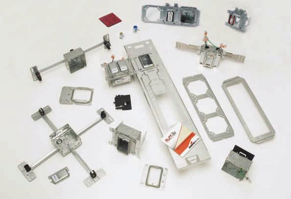


1 BLFRITRI-09 Ruff-IN Pre-Fab Systems


2 Table of Contents Table of Contents Introduction Ruff-IN & Total Ruff-IN Service Advisors Explanation of Offerings Quick Ship Program Configurator Information & 7 Pictorial Index & 9 Ruff-IN Section Croc-Lok Box Mounting Brackets & Assemblies & 11 Telescoping Slider Brackets & Assemblies & 13 Floor Mount Box Supports & Assemblies & 15 Double Sided Box Support Brackets & Assemblies.. 16 & 17 Single Side Box Support & Assemblies Uni-Mount Box Support & Assemblies Multiple Box Mounting Bracket & Assemblies & 21 Open Box Support Bracket & Assemblies & 23 Conduit & Box Support Fasteners & 25 Electrical Box T-Bar Fasteners & Assemblies & 27 T-Bar Fan / Fixture Support Plaster Rings with Wiring Devices Ruff-IN MC Cable Solutions Section Total Ruff-IN Introduction & Step 1 - Send in drawings Step 2 - Project Questionnaire Step 3 - Quotation Package Step 4 - Approval Package Room Drawing Explanation Labeling & Packaging Ruff-In Assemblies w/ MC Cable - Option & 39 Ruff-In Assemblies w/ MC Cable - Option & 41 MC Cable Whips & 43 Accessories SpecSeal Powershield (Firestop Pads) Metal Protector Plates Adjustable Plaster Rings Plaster Rings Boxes Conduit/Cable Connectors Wiring Devices - Receptacles & 51 Introduction Ruff-IN Total Ruff-IN Accessories We Give You Total Flexibility Wiring Devices - Switches & 53 ArrowLink Modular Wiring Devices &

3 Service Advisors Ruff-IN Service Advisor How The Service Advisor Works B-Line knows that your time is important! That s why the color-coding system in this catalog is designed to help you select products that fit your service needs. Products are marked to indicate the typical lead time for orders of Ruff-IN assemblies. Customer: How do I select my brackets, boxes, plaster rings, and devices so that I get the quickest turnaround? Service Advisor: Each part of our selection chart is shown in colors. If any section of a part number is a different color, the part will typically ship with the longer lead time represented by the colors. Basic Ruff-IN = 3 to 5 day lead time for quantities of 1000 or less Ruff-IN w/wiring Devices = 10 to 15 day lead time for quantities of 500 or less. Non Stock Components = Call factory for lead time. Introduction Example: BB216TS A - P GBW Call factory for lead time (from page 5) because of the Non Stock Lead time(days) call wiring device. factory Changing the part number from GBW to EBW will change the coding to yellow for the wiring device. The new lead time for the assembly would be working days because of the standard device. Ruff-IN MC Cable Solutions Service Advisor New Service Advisor Ruff-IN with MC Cables Service Advisor MC Cable Whips Only = 3-5 days for Quantities of 1000 or less Ruff-IN with MC cable = days for Quantities of 1000 or less Total Ruff-IN Quotation = 1-5 days* Total Ruff-IN Order = days* * Lead time varies depending on the project scope 3

4 Explanation of Offerings Introduction B-Line Has The Total Pre-Fab Offering No matter what your preference for pre-fab may be, B-Line has it! Choose the pre-fab offering below that best fits your needs: Basic Ruff-IN Offering Contents: Bracket, Box, Mud Ring, Ground Wire Ideal solution for a contractor sampling pre-fab for the first time that wants to keep the control of his or her project. Published lead times of 3-5 days ARO, and NEXT DAY SHIPPING ON (16) QUICK-SHIP ASSEMBLIES. Ruff-IN with Wiring Devices Offering Contents: Bracket, Box, Mud Ring, Wiring Assembly, Device or ArrowLink Connector, Protective Cover Plate Assemblies are pre-wired for quick plug-and-play installation using Wago or wire nut connectors. Choose from over 100 cataloged device options Cooper Wiring Device's ArrowLink connector is offered in a pre-wired Ruff-IN assembly. Using the Ruff-IN Configurator, design each part number included in your project BOM, then click on icons to instantly view assembly and wire configuration drawings. Ruff-IN with MC cables Offering Contents: Basic Ruff-IN with Wiring Assembly, Device or ArrowLink Connector, Protective Cover Plate, MC Cable whip with MC connector(s) Pre-wired Ruff-IN assemblies with devices and a pre-cut MC cable whip attached. Whip lengths available in 5-foot increments. Includes option to order MC cable whips only. Offering explained further on pages Total Ruff-IN Offering Contents: Engineering Take-off Service, Ruff-IN Assemblies, and MC Cable Whips Perfect for a contractor interested in trying pre-fab for the first time that needs the engineering and assembly expertise of B-Line. Industry leading, published lead times for Total Ruff-IN quotation responses and order assembly. For more details, see pages
5 Programs Quick Ship Program Next Day Shipping Available on 16 Ruff-In Assemblies No need to request a lead time, order today and we ll ship out of stock tomorrow! Introduction BBF DA BB D BB216TS-1104D Croc-Lok w/ box Ruff-IN Quick Ship Pre-Fab Assemblies CBL Part # UPC # Description Maximum BBF Series Floor-mount Order Qty. BBF DA " BBF floor-mount, 1-gang 5 /8" plaster ring, TP403 box, stranded ground wire 300 BBF D " BBF floor-mount, 1-gang 5 /8" plaster ring, TP403 box, solid ground wire 150 BBF DA " BBF floor-mount, 1-gang 3 /4" plaster ring, TP403 box, stranded ground wire 150 BBF D " BBF floor-mount, 1-gang 3 /4" plaster ring, TP403 box, solid ground wire 150 Double-Sided Box Support BB DA " Double-sided box support 1-gang 5 /8" plaster ring, TP403 box, stranded ground wire 300 BB D " Double-sided box support 1-gang 5 /8" plaster ring, TP403 box, solid ground wire 150 BB DA " Double-sided box support 1-gang 3 /4" plaster ring, TP403 box, stranded ground wire 150 BB D " Double-sided box support 1-gang 3 /4" plaster ring, TP403 box, solid ground wire 150 Telescoping Slider Bracket BB216TS-1104DA " Telescoping Slider Brkt,1-gang 5 /8" plaster ring, TP403 box, stranded ground wire 300 BB216TS-1104D " Telescoping Slider Brkt, 1-gang 5 /8" plaster ring, TP403 box, solid ground wire 150 BB216TS-1124DA " Telescoping Slider Brkt, 1-gang 3 /4" plaster ring, TP403 box, stranded ground wire 150 BB216TS-1124D " Telescoping Slider Brkt, 1-gang 3 /4" plaster ring, TP403 box, solid ground wire 150 Croc-Lok & Telescoping Bracket BB2CL-1104DA Croc-Lok w/ box, 1-gang 5 /8" plaster ring, TP403 box, stranded ground wire 300 BB2CL-1104D Croc-Lok w/ box, 1-gang 5 /8" plaster ring, TP403 box, solid ground wire 150 BB2CL-1124DA Croc-Lok w/ box, 1-gang 3 /4" plaster ring, TP403 box, stranded ground wire 150 BB2CL-1124D Croc-Lok w/ box, 1-gang 3 /4" plaster ring, TP403 box, solid ground wire 150 BB2-16T " Telescoping Bracket -- BB2-24T " Telescoping Bracket -- Need a way to separate yourself from the competition? Boxed BBF18 Series Boxed BB216TS Series Ruff-IN assemblies can be stocked at your local distributor. Ask your Cooper B-Line Sales Representative for more information on stock-able Ruff-IN assemblies. 5


6 Ruff-IN Configurator Introduction Introducing Cooper B-Line s Ruff-IN Configurator - Developed to be the ideal solution for creating a project bill of material. Download the Ruff-IN configurator at and see for yourself how easy it is to navigate through the component selection process! Create Assembly Selection Tab Determine project savings when using Ruff-IN assemblies by clicking on the link to the Ruff-IN Labor Savings Calculator Wiring Configuration Drawing For assemblies that include wiring devices, the configurator provides a wiring configuration drawing that details exactly how the wiring device will be wired in the assembly. Note: Voice Demo Training Video Tutorial is available at 6


7 Ruff-IN Configurator Project Rooms/Floors Tab Organize Project BOMs to ship by specific room and/or floor Introduction 3-D Assembly Drawing Instantly view a 3-D assembly drawing of your configured assembly Project Summary Tab Click to automatically request a quote for your project! 7

8 Initial for Approval (For multiple shipdate option see page 2) Initial for Approval Contractor Name Contractor Name CONTRACTOR SUGGESTED DATE Attachment: Contractor Signature Contractor Signature Pictorial Index Introduction Croc-Lok Box Mount Bracket Pages 10 & 11 Telescoping Slider Bracket Pages 12 & 13 Floor Mount Box Support Pages 14 & 15 Double Sided Box Support Pages 16 & 17 Single Sided Box Support Page 18 Uni-Mount Box Support Page 19 Multiple Box Mounting Bracket Pages 20 & 21 Open Box Support Bracket Pages 22 & 23 Conduit & Box Support Fasteners Pages 24 & 25 Electrical Box T-Bar Fasteners Pages 26 & 27 Fan/Fixture Hanger Assembly Page 28 Plaster Rings With Wiring Devices Page 29 Ruff-IN Contractor Review Sheet (PF-APPROVALFORM-RUFFIN) Job Name: PO #: B-Line Order #: Shipdate for Complete Order Project Scope CONTRACTOR SIGNATURE OF APPROVAL FOR ASSEMBLY DRAWINGS I certify the assembly drawings and other quantities presented on have been reviewed and are correct. I am aware that any changes requested and/or made to these drawings could extend the project lead time. CONTRACTOR SIGNATURE OF APPROVAL FOR ROOM DRAWINGS I certify the room drawings detailing assembly and whip location within each room that are presented on have been reviewed and are correct. I am aware that any changes requested and/or made to these drawings could extend the project lead time. * Fax this sheet to ( , ATTN: Ruff-IN * approval to bline.ruffin@cooperindustries.com is also acceptable Total Ruff-IN Steps 1 & 2 Send in Drawings and Complete Project Questionnaire Pages 32 & 33 Total Ruff-IN Steps 3 & 4 Quotation & Approval Packages Pages 34 & 35 Room Drawing Explanation, Labeling & Packaging Pages 36 & 37 Ruff-IN Assemblies with MC Cable - Option 1 38 &39 Ruff-IN Assemblies with MC Cable - Option 2 Pages 40 & 41 Ruff-IN MC Cable Whips Pages 42 & 43 8


9 Pictorial Index Introduction Firestop Pads Page 45 Protector Plates Page 46 Adj. Plaster Rings Page 47 Plaster Rings Page 47 Electrical Boxes Page 48 Cable & Conduit Connectors Page 49 Wiring Devices - Receptacles Pages 50 & 51 Wiring Devices - Switches Pages 52 & 53 ArrowLink is available with every bracket option that includes the choice to add a wiring device. Each brochure page includes information on how ArrowLink can be added to an assembly. Assemblies will be pre-wired with ArrowLink connector end included to allow for quick cable installation. Assemblies include a cover plate attached to the mud ring for additional protection. The ArrowLink Modular devices are sold separately. See your local Cooper Wiring Device representative for details. For more information on ArrowLink Modular Devices see pages 54 & 55. ArrowLink Modular Wiring Devices with Ruff-IN Pre-Fab Assemblies The ArrowLink Connector end is now available as an accessory in the Ruff-IN Pre-Fab Systems offering. Pages 54 & 55 9

10 Croc-Lok Box Mounting Bracket BB2CL New Features The tool-less design enables Croc-Lok assemblies to be field installed in less than 4 seconds. Simply squeeze, secure and walk away. Outlet boxes mount to the Croc-Lok with single screw. The Croc-Lok Box Mounting Bracket is an improved version of the current BB2TS Slider Bracket. Recently redesigned to include raised dimples that lock into holes on the telescoping bar. Redesign includes screw holes in the face plate, which create the option to screw the Croc-Lok to a telescoping bar Ruff-IN UPC/Part Number Catalog Number BB2CL installed on BB2-16T Stud Spacing Description Box Qty BB2CL N/A Croc-Lok only BB216TCL 11 to 16 BB2-16T with Croc-Lok BB224TCL 15 to 24 BB2-24T with Croc-Lok 20 Patent Pending Note: Secures to Cooper B-Line BB2-16T and BB2-24T telescoping brackets only. For a standard 2 1 /8 deep box, the stud depth must be 3 1 /2 or greater. For a shallow 1 1 /2 deep box, the stud depth must be 2 1 /2 or greater. Telescoping Bar with Croc-Lok Assemblies BB216TCL Features The Croc-Lok Box Mounting Bracket is an improved version of the current BB2TS Slider Bracket. The narrow width of the Croc-Lok allows for up to three - 4 boxes to be installed within a 16 stud spacing, and up to four - 4 boxes within a 24 stud spacing. Its design offers placement flexibility by locking in place firmly at any position along the telescoping bar. Croc-Lok box assemblies are sold with or without telescoping bars. To reduce the lines on your BOM consider ordering Croc-Lok box assemblies and field install. Croc-Lok box assemblies can be attached before or after the telescoping bar is mounted in the stud wall. Download the Ruff-IN configurator for free at and see for yourself how much easier it allows you to create Ruff-IN part numbers. BB2CL-4D BB2CL-2104DA-WAAR Basic Ruff-IN = 3-5 day lead-time for quantities of 1000 or less. Ruff-IN with Wiring Devices = day lead-time for quantities of 500 or less. Non Stock Components = Call factory for lead-time. 10
11 Croc-Lok Box Mounting Bracket Assemblies Example Part Number BB216TCL D A _ - - W AAR BB Step 1 Step 2 Step 3 For Installation Of One Box Step 1 Step 2 Step 3 For Installation Of Second Box - If Desired Step 1 - Basic Ruff-In Step 2 - Connectors Step 3 - Wiring Devices 1 Stud Spacing BB216TCL = 11 to 18 Mounting Bar & Croc-Loc Assembly BB224TCL = 15 to 26 Mounting Bar & Croc-Loc Assembly BB2CL = Croc-Loc Assembly Only 2 Plaster Ring Style (see ps. 47) 1 = One Device 2 = Two Device R = Round 1AJ = One Device Adjustable * 2AJ = Two Device Adjustable * Blank = Box Only 3 Plaster Ring Size 04 = 1 /4 Raise 08 = 1 /2 Raise 10 = 5 /8 Raise 12 = 3 /4 Raise 16 = 1 Raise 20 = 1 1 /4 Raise 24 = 1 1 /2 Raise 32 = 2 Raise Blank = Box Only or Adjustable Plaster Ring 4 Box Style (see pg. 48) 4D = 4 Sq., 2 1 /8 Deep 436 = 4 Sq., 2 1 /8 Deep, 1 KO 4 = 4 Sq., 1 1 /2 Deep 432 = 4 Sq., 2 1 /8 Deep, 3 /4 KO 5D = 4 11 /16 Sq., 2 1 /8 Deep 560 = 4 11 /16 Sq., 2 1 /8 Deep, 1 KO 5 = 4 11 /16 Sq., 1 1 /2 Deep 554 = 4 11 /16 Sq., 2 1 /8 Deep, 3 /4 KO 7 Connector Top Left KO Blank = No Attachment L = Attachment Present 8 Connector Type (see pg. 49) Blank = None A = QLK50S ( 1 /2 single MC) B = QLK50D ( 1 /2 double MC) C = QLK75 ( 3 /4 single MC) D = SSBC50 ( 1 /2 EMT Connector) E = SSBC75 ( 3 /4 EMT Connector) F = SSBC100 (1 EMT Connector) 9 Connector Top Middle KO Blank = No Attachment M = Attachment Present 10 Connector Top Right KO Blank = No Attachment R = Attachment Present * One device adjustable plaster rings are set at 3 /4 raise and can be adjusted to 1 1 /2 raise. Two device adjustable plaster rings are set at 5 /8 raise and can be adjusted to 1 1 /2 raise. Adjustable plaster ring can only be used on 4 sq /8 deep boxes. 11 Wire Configuration P = Pigtails w/4 Hole 1 Wago (all receptacles installed w/ground up) R = Pigtails w/4 Hole Wago (all receptacles installed w/ground down) W = No Pigtails Wires Contained Inside Box (all receptacles installed w/ground up) Y = No Pigtails Wires Contained Inside Box (all receptacles installed w/ground down) M = Pigtails w/ Bare Wire Ends extending from top KOs, Twist-On Wire Connectors Inside Box (all receptacles installed w/ground up) N = Pigtails w/ Bare Wire Ends extending from top KOs, Twist-On Wire Connectors Inside Box (all receptacles installed w/ground down) Note: P, R, M and N configurations not available if KO connectors are installed on the outlet box 12 Device Type or ArrowLink Connector Options Standard Device Type (see pgs ) 3 Letter Designator For 1 Device Two 3 Letter Designators For 2 Different Devices One 3 Letter Designator For 2 Of The Same Device ArrowLink Connector Options (for more information see pgs ) New MCR = ArrowLink Connector, Receptacle/GFCI MCS = ArrowLink Connector, Single-Pole Switch Ruff-IN 5 Ground Wire (Pre-installed devices require stranded wire) Blank = Solid Ground Wire A = Stranded Ground Wire N = No Ground Wire 6 Firestop Pad (see pg. 45) Blank = No Pad F = Pad Installed BB216TCL-1104DA-WAAR BB216TCL-1104DA-24DA-WAAR 11


 BB216TS assemblies, see page 5 for more information on the Ruff-IN Quick Ship Program.")
12 Telescoping Slider Brackets BB216TS BB224TS Features The industry s only fully adjustable pre-fab bracket - fits a range of stud spacings and both 1 1 /2 and 2 1 /8 deep boxes. Box can be attached to slider bracket before or after slider is installed on telescoping bracket. Box location can be field-adjusted by moving slider along telescoping bracket. Pre-assembled units available with two (2) boxes if desired. UPC/Part Number Catalog Number Stud Spacing Description Box Qty Ruff-IN BB216TS 11 to 18 BB2-16T with Slider Bracket BB224TS 15 to 26 BB2-24T with Slider Bracket BB2TS -- Slider Bracket Only 50 Patent # 7,472,875 Telescoping Slider Bracket Assemblies BB216TS-1104D BB216TS-2104D-14DN Features Ruff-In assemblies available with box, plaster ring and ground wire. Wiring devices available installed with 2 1 /8 deep boxes. Metal protector plate provided with all wiring device assemblies. Fire stop pad and cable/conduit connectors can also be pre-installed if desired. Next day shipping available on (4) BB216TS assemblies, see page 5 for more information on the Ruff-IN Quick Ship Program. Download the Ruff-IN configurator for free at and see for yourself how much easier it allows you to create Ruff-IN part numbers. BB216TS-2104DA-LARA-WKAV-14DN BB216TS-2104DA-PGBW 12
13 Telescoping Slider Bracket Assemblies Example Part Number from page 12 BB216TS D A _ - - P GBW BB Step 1 Step 2 Step 3 For Installation Of One Box Step 1 Step 2 Step 3 For Installation Of Second Box - If Desired Step 1 - Basic Ruff-In Step 2 - Connectors Step 3 - Wiring Devices 1 Stud Spacing BB216TS = BB224TS = Plaster Ring Style (see pg. 47) 1 = One Device 2 = Two Device R = Round 1AJ = One Device Adjustable * 2AJ = Two Device Adjustable * Blank = Box Only 3 Plaster Ring Size 04 = 1 /4 Raise 08 = 1 /2 Raise 10 = 5 /8 Raise 12 = 3 /4 Raise 16 = 1 Raise 20 = 1 1 /4 Raise 24 = 1 1 /2 Raise 32 = 2 Raise Blank = Box Only or Adjustable Plaster Ring 7 Connector Top Left KO Blank = No Attachment L = Attachment Present 8 Connector Type (see pg. 49) Blank = None A = QLK50S ( 1 /2 single MC) B = QLK50D ( 1 /2 double MC) C = QLK75 ( 3 /4 single MC) D = SSBC50 ( 1 /2 EMT Connector) E = SSBC75 ( 3 /4 EMT Connector) F = SSBC100 (1 EMT Connector) 9 Connector Top Middle KO Blank = No Attachment M = Attachment Present 10 Connector Top Right KO Blank = No Attachment R = Attachment Present 11 Wire Configuration P = Pigtails w/4 Hole 1 Wago (all receptacles installed w/ground up) R = Pigtails w/4 Hole Wago (all receptacles installed w/ground down) W = No Pigtails Wires Contained Inside Box (all receptacles installed w/ground up) Y = No Pigtails Wires Contained Inside Box (all receptacles installed w/ground down) M = Pigtails w/ Bare Wire Ends extending from top KOs, Twist-On Wire Connectors Inside Box (all receptacles installed w/ground up) N = Pigtails w/ Bare Wire Ends extending from top KOs, Twist-On Wire Connectors Inside Box (all receptacles installed w/ground down) Note: P, R, M and N configurations not available if KO connectors are installed on the outlet box 12 Device Type or ArrowLink Connector Options Standard Device Type (see pgs ) Ruff-IN 4 Box Style (see pg. 48) 4D = 4 Sq., 2 1 /8 Deep 436 = 4 Sq., 2 1 /8 Deep, 1 KO 4 = 4 Sq., 1 1 /2 Deep 432 = 4 Sq., 2 1 /8 Deep, 3 /4 KO 5D = 4 11 /16 Sq., 2 1 /8 Deep 560 = 4 11 /16 Sq., 2 1 /8 Deep, 1 KO 5 = 4 11 /16 Sq., 1 1 /2 Deep 554 = 4 11 /16 Sq., 2 1 /8 Deep, 3 /4 KO 5 Ground Wire (Pre-installed devices require stranded wire) Blank = Solid Ground Wire A = Stranded Ground Wire N = No Ground Wire * One device adjustable plaster rings are set at 3 /4 raise and can be adjusted to 1 1 /2 raise. Two device adjustable plaster rings are set at 5 /8 raise and can be adjusted to 1 1 /2 raise. Adjustable plaster ring can only be used on 4 sq /8 deep boxes. 3 Letter Designator For 1 Device Two 3 Letter Designators For 2 Different Devices One 3 Letter Designator For 2 Of The Same Device ArrowLink Connector Options (for more information see pgs ) New MCR = ArrowLink Connector, Receptacle/GFCI MCS = ArrowLink Connector, Single-Pole Switch 6 Firestop Pad (see pg. 45) Blank = No Pad F = Pad Installed Basic Ruff-IN = 3-5 day lead-time for quantities of 1000 or less. Ruff-IN with Wiring Devices = day lead-time for quantities of 500 or less. Non Stock Components = Call factory for lead-time. 13
14 Floor Mount Box Supports Features New BBF floorstand provides the most rigid support in the industry. Far-side support accommodates 6, 5 1 /2, 3 1 /2, and 2 1 /2 stud depths. Fold-out tab built-in to attach floor stand to stud if desired. Integral wings provide rigid support when floorstand is mounted between studs. Optional cable containment clip securely attaches to floorstand without hardware. Finish: Pre-galvanized. New BBF18 UPC/Part Number Catalog Number Box Center Height Box Qty Ruff-IN BBFC BBFxxC Patent Pending BBF15 15 Floorstand BBF18 18 Floorstand BBF24 24 Floorstand BBFC Cable Containment Clip BBF15C 15 Floorstand 25 with Cable Containment Clip BBF18C 18 Floorstand 25 with Cable Containment Clip BBF24C 24 Floorstand 25 with Cable Containment Clip Floor Mount/Single Side Box Support Combo Assemblies Features Wiring devices available installed with 2 1 /8 deep boxes. Bottom kick plate depth shortened to slide under stud track more easily. Double-sided bracket can be ganged to floor stand for multiple box applications. Patented Marty-Mouse ears enable boxes to be secured in place with or without the plaster rings. Available in three (3) bracket sizes - 15, 18, and 24. Next day shipping available on (4) BBF18 assemblies, see page 5 for more information on the Ruff-IN Quick-Ship Program. Download the Ruff-IN configurator for free at and see for yourself how much easier it allows you to create Ruff-IN part numbers. BBF DA-2104DA 14
15 Floor Mount Box Support & Assemblies Example Part Number shown below BBF18 _ - _ D A _ - - W GDW Step 1 Step 2 Step 3 For Installation Of One Box Step 1 Step 2 Step 3 For Installation Of Second Box - If Desired Step 1 - Basic Ruff-In Step 1 - Basic Ruff-In (cont.) Step 3 - Wiring Devices 1 BBF15 = 15 BBF18 = 18 BBF24 = 24 Box Height 2 Cable Containment C = Include cable containment Blank = Do not include cable containment 3 Stud Depth for Optional Second Box Blank = No additional bracket 3 = 3 1 /2 & 2 1 /2 4 = 4, 3 1 /2 & 2 1 /2 5 = 6, 5 1 /2, 3 1 /2 & 2 1 /2 4 Plaster Ring Style (see pg. 47) 1 = One Device 2 = One Device R = Round 1AJ = One Device Adjustable * 2AJ = Two Device Adjustable * Blank = Box Only 5 Plaster Ring Size 04 = 1 /4 Raise 08 = 1 /2 Raise 10 = 5 /8 Raise 12 = 3 /4 Raise 16 = 1 Raise 20 = 1 1 /4 Raise 24 = 1 1 /2 Raise 32 = 2 Raise Blank = Box Only or Adjustable Plaster Ring 7 Ground Wire (Pre-installed devices require stranded wire) Blank = Solid Ground Wire A = Stranded Ground Wire N = No Ground Wire 8 Firestop Pad (see pg. 45) Blank = No Pad F = Pad Installed Step 2 - Connectors 9 Connector Top Left KO Blank = No Attachment L = Attachment Present 10 Connector Type (see pg. 49) Blank = None A = QLK50S ( 1 /2 single MC) B = QLK50D ( 1 /2 double MC) C = QLK75 ( 3 /4 single MC) D = SSBC50 ( 1 /2 EMT Connector) E = SSBC75 ( 3 /4 EMT Connector) F = SSBC100 (1 EMT Connector) 11 Connector Top Middle KO Blank = No Attachment M = Attachment Present 12 Connector Top Right KO Blank = No Attachment R = Attachment Present 13 Wire Configuration P = Pigtails w/4 Hole Wagos (all receptacles installed w/ground up) R = Pigtails w/4 Hole Wago (all receptacles installed w/ground down) W = No Pigtails Wires Contained Inside Box (all receptacles installed w/ground up) Y = No Pigtails Wires Contained Inside Box (all receptacles installed w/ground down) M = Pigtails w/ Bare Wire Ends extending from top KOs, Twist-On Wire Connectors Inside Box (all receptacles installed w/ground up) N = Pigtails w/ Bare Wire Ends extending from top KOs, Twist-On Wire Connectors Inside Box (all receptacles installed w/ground down) Note: P, R, M and N configurations not available if KO connectors are installed on the outlet box 14 Device Type or ArrowLink Connector Options Standard Device Type (see pgs ) 3 Letter Designator For 1 Device Two 3 Letter Designators For 2 Different Devices One 3 Letter Designator For 2 Of The Same Device ArrowLink Connector Options (for more information see pgs ) New MCR = ArrowLink Connector, Receptacle/GFCI MCS = ArrowLink Connector, Single-Pole Switch Ruff-IN 6 Box Style (see pg. 48) 4D = 4 Sq., 2 1 /8 Deep 436 = 4 Sq., 2 1 /8 Deep, 1 KO 4 = 4 Sq., 1 1 /2 Deep 432 = 4 Sq., 2 1 /8 Deep, 3 /4 KO 5D = 4 11 /16 Sq., 2 1 /8 Deep 560 = 4 11 /16 Sq., 2 1 /8 Deep, 1 KO 5 = 4 11 /16 Sq., 1 1 /2 Deep 554 = 4 11 /16 Sq., 2 1 /8 Deep, 3 /4 KO 431 = 4 Sq., 2 1 /8 Deep, Int. MC Connectors Blank = Plaster Ring Only * One device adjustable plaster rings are set at 3 /4 raise and can be adjusted to 1 1 /2 raise. Two device adjustable plaster rings are set at 5 /8 raise and can be adjusted to 1 1 /2 raise. Adjustable plaster ring can only be used on 4 sq /8 deep boxes. Basic Ruff-IN = 3-5 day lead-time for quantities of 1000 or less. Ruff-IN with Wiring Devices = day lead-time for quantities of 500 or less. Non Stock Components = Call factory for lead-time. BBF DA-WGDW BBF15C-1104DA-UMCR 15

.")

16 Double Sided Box Support Bracket with patented Marty-Mouse Ears BB74 shown Features Double side box support designed for Pre-Fab installations. Unit can be installed on either side of stud without repositioning box or devices. Patented Marty-Mouse Ears feature an innovative keyhole pattern to secure outlet box to bracket with or without plaster ring. Marty-Mouse Ears simplify wiring of pre-fab units. Plaster ring can be removed for full access to box contents while box remains in place. Wider box opening accommodates one or two gang adjustable plaster rings (B1AJ & B2AJ - see pg. 47). Enhanced far-side support stands up during drywall installation and out performs competitor brackets. Finish: Pre-Galvanized Ruff-IN UPC/Part Number Catalog Number Stud Size Box Qty BB /2 & 2 1 / BB74 4, 3 1 /2 & 2 1 / BB76 6, 5 1 /2, 3 1 /2, 2 1 /2 25 Patent # Double Sided Box Support Bracket Assemblies BB D Features Ruff-In assemblies available with box, plaster ring and ground wire. Wiring devices available installed with 2 1 /8 deep boxes. Metal protector plated provided with all wiring device assemblies. Fire stop pad and cable/conduit connectors can also be pre-installed if desired. Next day shipping available on (4) BB76 assemblies, see page 5 for more information on the Ruff-IN Quick-Ship Program. Download the Ruff-IN configurator for free at and see for yourself how much easier it allows you to create Ruff-IN part numbers. BB D BB D BB D-LAMARA BB D-LAMARAPWAAW BB DA-PAAW 16
17 Double Sided Box Support Bracket Example Part Number from page 16 BB D A _ - - P AAW BB Step 1 Step 2 Step 3 Step 1 - Basic Ruff-In Step 2 - Connectors Step 3 - Wiring Devices 1 Stud Depth BB73 = 3 1 /2 & 2 1 /2 BB74 = 4, 3 1 /2 & 2 1 /2 BB76 = 6, 5 1 /2, 3 1 /2 & 2 1 /2 2 Plaster Ring Style (see pg. 47) 1 = One Device 2 = Two Device R = Round 1AJ = One Device Adjustable * 2AJ = Two Device Adjustable * Blank = Box Only 3 Plaster Ring Size 04 = 1 /4 Raise 08 = 1 /2 Raise 10 = 5 /8 Raise 12 = 3 /4 Raise 16 = 1 Raise 20 = 1 1 /4 Raise 24 = 1 1 /2 Raise 32 = 2 Raise Blank = Box Only or Adjustable Plaster Ring 4 Box Style (see pg. 48) 4D = 4 Sq., 2 1 /8 Deep 436 = 4 Sq., 2 1 /8 Deep, 1 KO 4 = 4 Sq., 1 1 /2 Deep 432 = 4 Sq., 2 1 /8 Deep, 3 /4 KO 5D = 4 11 /16 Sq., 2 1 /8 Deep 560 = 4 11 /16 Sq., 2 1 /8 Deep, 1 KO 5 = 4 11 /16 Sq., 1 1 /2 Deep 554 = 4 11 /16 Sq., 2 1 /8 Deep, 3 /4 KO 431 = 4 Sq., 2 1 /8 Deep, Int. MC Connectors Blank = Plaster Ring Only 7 Connector Top Left KO Blank = No Attachment L = Attachment Present 8 Connector Type (see pg. 49) Blank = None A = QLK50S ( 1 /2 single MC) B = QLK50D ( 1 /2 double MC) C = QLK75 ( 3 /4 single MC) D = SSBC50 ( 1 /2 EMT Connector) E = SSBC75 ( 3 /4 EMT Connector) F = SSBC100 (1 EMT Connector) 9 Connector Top Middle KO Blank = No Attachment M = Attachment Present 10 Connector Top Right KO Blank = No Attachment R = Attachment Present * One device adjustable plaster rings are set at 3 /4 raise and can be adjusted to 1 1 /2 raise. Two device adjustable plaster rings are set at 5 /8 raise and can be adjusted to 1 1 /2 raise. Adjustable plaster ring can only be used on 4 sq /8 deep boxes. 11 Wire Configuration P = Pigtails w/4 Hole Wago (all receptacles installed w/ground up) R = Pigtails w/4 Hole Wago (all receptacles installed w/ground down) W = No Pigtails Wires Contained Inside Box (all receptacles installed w/ground up) Y = No Pigtails Wires Contained Inside Box (all receptacles installed w/ground down) M = Pigtails w/ Bare Wire Ends extending from top KOs, Twist-On Wire Connectors Inside Box (all receptacles installed w/ground up) N = Pigtails w/ Bare Wire Ends extending from top KOs, Twist-On Wire Connectors Inside Box (all receptacles installed w/ground down) Note: P, R, M and N configurations not available if KO connectors are installed on the outlet box 12 Device Type or ArrowLink Connector Options Standard Device Type (see pgs ) 3 Letter Designator For 1 Device Two 3 Letter Designators For 2 Different Devices One 3 Letter Designator For 2 Of The Same Device ArrowLink Connector Options (for more information see pgs ) New MCR = ArrowLink Connector, Receptacle/GFCI MCS = ArrowLink Connector, Single-Pole Switch Ruff-IN 5 Ground Wire (Pre-installed devices require stranded wire) Blank = Solid Ground Wire A = Stranded Ground Wire N = No Ground Wire 6 Firestop Pad (see pg. 45) Blank = No Pad F = Pad Installed BB DA-PMCR (cover plate not shown) Basic Ruff-IN = 3-5 day lead-time for quantities of 1000 or less. Ruff-IN with Wiring Devices = day lead-time for quantities of 500 or less. Non Stock Components = Call factory for lead-time. 17
18 Single Sided Box Support & Assemblies Ruff-IN BB4-23 BB4-4 BB4-6 Features Improved far-side support prevents box movement in wall cavity. Adjustable far-side supports designed to reduce labor. Brackets may be piggy-backed in series.. Ruff-In assemblies available with box, plaster ring and ground wire. Not recommended for pre-installed wiring devices. See pages for an improved Pre-Fab assembly solution. Download the Ruff-IN configurator for free at and see for yourself how much easier it allows you to create Ruff-IN part numbers. UPC/Part Number Catalog Number Stud Size Box Qty BB /2 & 2 1 / BB4-4 4, 3 1 /2 & 2 1 / BB4-6 6, 5 1 /2, 3 1 /2, 2 1 /2 100 BB DN Single Sided Box Support Bracket Assemblies Example Part Number BB D BB BB D BB D 1 Stud Depth 4 Box Style (see pg. 48) 5 Ground Wire 2 BB423 = 3 1 /2 & 2 1 /2 BB44 = 4, 3 1 /2 & 2 1 /2 BB46 = 6, 5 1 /2, 3 1 /2 & 2 1 /2 Plaster Ring Style (see pg. 47) 1 = One Device 2 = Two Device R = Round 1AJ = One Device Adjustable * Blank = Box Only 4D = 4 Sq., 2 1 /8 Deep 436 = 4 Sq., 2 1 /8 Deep, 1 KO 4 = 4 Sq., 1 1 /2 Deep 432 = 4 Sq., 2 1 /8 Deep, 3 /4 KO 5D = 4 11 /16 Sq., 2 1 /8 Deep 560 = 4 11 /16 Sq., 2 1 /8 Deep, 1 KO 5 = 4 11 /16 Sq., 1 1 /2 Deep 554 = 4 11 /16 Sq., 2 1 /8 Deep, 3 /4 KO 431 = 4 Sq., 2 1 /8 Deep, Int. MC Connectors Blank = Plaster Ring Only 6 Blank = Solid Ground Wire A = Stranded Ground Wire N = No Ground Wire Firestop Pad (see pg. 45) Blank = No Pad F = Pad Installed 3 Plaster Ring Size 04 = 1 /4 Raise 08 = 1 /2 Raise 10 = 5 /8 Raise 12 = 3 /4 Raise 16 = 1 Raise 20 = 1 1 /4 Raise 24 = 1 1 /2 Raise 32 = 2 Raise Blank = Box Only or Adjustable Plaster Ring * One device adjustable plaster rings are set at 3 /4 raise and can be adjusted to 1 1 /2 raise. Adjustable plaster ring can only be used on 4 sq /8 deep boxes. Basic Ruff-IN = 3-5 day lead-time for quantities of 1000 or less. Non Stock Components = Call factory for lead-time. 18
19 Uni-Mount Box Support & Assemblies Features Uni-Mount provides a secure box support and features a built-in plaster ring. Rigid bracket design eliminates the need for far-side support. Guide tabs ensure alignment on studs. Ruff-In assemblies available with box, plaster ring and ground wire. Fire stop pad can be pre-installed in boxes if desired. Not recommended for pre-installed wiring devices. See pages for an improved Pre-Fab assembly solution. Download the Ruff-IN configurator for free at and see for yourself how much easier it allows you to create Ruff-IN part numbers. UPC/Part Number Catalog Number Plaster Ring Box Qty BB /2 raise BB /8 raise BB /4 raise BB /2 raise BB /8 raise BB /4 raise 50 BB40-10 BB45-8 Ruff-IN Uni-Mount Box Support Assemblies Example Part Number BB D BB BB DN 1 Plaster Ring Style BB40 = One Device BB45 = Two Device 2 Plaster Ring Size 08 = 1 /2 Raise 10 = 5 /8 Raise 12 = 3 /4 Raise 4 Ground Wire Blank = Solid Ground Wire A = Stranded Ground Wire N = No Ground Wire 5 Firestop Pad (see pg. 45) Blank = No Pad F = Pad Installed BB D 3 Box Style (see pg. 48) 4D = 4 Sq., 2 1 /8 Deep 436 = 4 Sq., 2 1 /8 Deep, 1 KO 4 = 4 Sq., 1 1 /2 Deep 432 = 4 Sq., 2 1 /8 Deep, 3 /4 KO 431 = 4 Sq., 2 1 /8 Deep, Int. MC Connectors Basic Ruff-IN = 3-5 day lead-time for quantities of 1000 or less. Non Stock Components = Call factory for lead-time. 19

20 Multiple Box Mounting Brackets Features BB8-16 Provides support for multiple boxes or plaster rings between studs 16 or 24 on center. Available factory assembled with plaster rings and/or boxes with ground wire to reduce labor. Custom factory assemblies are ordered by specifying plaster rings and/or boxes for each bracket position BB8-24 UPC/Part Number Catalog Number Stud Spacing Box Qty BB BB Ruff-IN Multiple Box Mounting Bracket Assemblies BB D-X-1-X Features Custom factory assemblies are ordered by specifying box information for each position opening. Ruff-In assemblies available with box, plaster ring and ground wire. Wiring devices available installed with 2 1 /8 deep boxes. Metal protector plate provided with all wiring device assemblies. Fire stop pad and cable/conduit connectors can be pre-installed in boxes if desired. Download the Ruff-IN configurator for free at and see for yourself how much easier it allows you to create Ruff-IN part numbers. BB D-1-1-X BB D-X-6-X BB D-X-1PCAA-X BB D-X-1WGBW-X BB D-X-1LARAWKAV-X 20
21 Multiple Box Mounting Bracket Assemblies Example Part Number from page 20 BB D - X - 1LARA WKAV- X - X BB Step 1 Step 2 Step 3 Step 2 Step 3 Step 2 Step 3 Step 2 Step 3 Position 1 Opening (if desired) Position 2 Opening (if desired) Position 3 Opening (if desired) Position Opening 4 (if desired) (on BB824 only) Step 1 - Basic Ruff-In Step 2 - Connectors Step 3 - Wiring Devices BB816 = 16 BB824 = 24 1 Stud Spacing 6 2 Plaster Ring Size 04 = 1 /4 Raise 08 = 1 /2 Raise 10 = 5 /8 Raise 12 = 3 /4 Raise 16 = 1 Raise 20 = 1 1 /4 Raise 24 = 1 1 /2 Raise 32 = 2 Raise Blank = Box Only or Adjustable Plaster Ring 3 Box Style (see pg. 48) 4D = 4 Sq., 2 1 /8 Deep 436 = 4 Sq., 2 1 /8 Deep, 1 KO 4 = 4 Sq., 1 1 /2 Deep 432 = 4 Sq., 2 1 /8 Deep, 3 /4 KO 5D = 4 11 /16 Sq., 2 1 /8 Deep 560 = 4 11 /16 Sq., 2 1 /8 Deep, 1 KO 5 = 4 11 /16 Sq., 1 1 /2 Deep 554 = 4 11 /16 Sq., 2 1 /8 Deep, 3 /4 KO 431 = 4 Sq., 2 1 /8 Deep, Int. MC Connectors 4 Ground Wire (Pre-installed devices require stranded wire) Blank = Solid Ground Wire A = Stranded Ground Wire N = No Ground Wire 5 Firestop Pad (see pg. 45) Blank = No Pad F = Pad Installed Note: If different box than called out in Step 1 is used in any position, enter the designator for the box after the character of the position. For example 14D or Position 1 = One Device and Box 2 = Two Device and Box J = One Device Adjustable Ring & Box * 3 = One Device Plaster Ring Only 4 = Two Device Plaster Ring Only 5 = Box Only R = Round Plaster Ring and Box 6 = One Device and Box, No Ground Wire 7 = Two Device and Box, No Ground Wire 8 = Round Plaster Ring and Box, No Ground Wire K = Adjustable Plaster Ring and Box, No Ground Wire 9 = Box Only, No Ground Wire X = No Attachments Only Options 1, 2, & J can be used with wiring devices. 7 Connector Top Left KO Blank = No Attachment L = Attachment Present 8 Connector Type (see pg. 49) Blank = None A = QLK50S ( 1 /2 single MC) B = QLK50D ( 1 /2 double MC) C = QLK75 ( 3 /4 single MC) D = SSBC50 ( 1 /2 EMT Connector) E = SSBC75 ( 3 /4 EMT Connector) F = SSBC100 (1 EMT Connector) 9 Connector Top Middle KO Blank = No Attachment M = Attachment Present 10 Connector Top Right KO Blank = No Attachment R = Attachment Present 11 Wire Configuration P = Pigtails w/4 Hole Wago (all receptacles installed w/ground up) R = Pigtails w/4 Hole Wagos (all receptacles installed w/ground down) W = No Pigtails Wires Contained Inside Box (all receptacles installed w/ground up) Y = No Pigtails Wires Contained Inside Box (all receptacles installed w/ground down) M = Pigtails w/ Bare Wire Ends extending from top KOs, Twist-On Wire Connectors Inside Box (all receptacles installed w/ground up) N = Pigtails w/ Bare Wire Ends extending from top KOs, Twist-On Wire Connectors Inside Box (all receptacles installed w/ground down) Note: P, R, M and N configurations not available if KO connectors are installed on the outlet box 12 Device Type or ArrowLink Connector Options Standard Device Type (see pgs ) 3 Letter Designator For 1 Device Two 3 Letter Designators For 2 Different Devices One 3 Letter Designator For 2 Of The Same Device ArrowLink Connector Options (for more information see pgs ) MCR = ArrowLink Connector, Receptacle/GFCI MCS = ArrowLink Connector, Single-Pole Switch * One device adjustable plaster rings are set at 3 /4 raise and can be adjusted to 1 1 /2 raise. Adjustable plaster ring can only be used on 4 sq /8 deep boxes. New Ruff-IN Basic Ruff-IN = 3-5 day lead-time for quantities of 1000 or less. Ruff-IN with Wiring Devices = day lead-time for quantities of 500 or less. Non Stock Components = Call factory for lead-time. 21


22 Open Box Support Mounting Brackets Features BB7-16 B-Line s new BB7 Series open box support secures boxes and plaster rings between studs 16 and 24 on center. Open design allows infinite adjustability, box can be placed in any horizontal location. Stamped markings at 1 /4, 1 /2 and 1 increments allow the installer to easilylocate the desired box position BB7-24 UPC/Part Number Catalog Number Stud Spacing Box Qty Ruff-IN BB BB Open Box Support Mounting Bracket Assemblies Features BB D-X-1-X BB D-2-X-2 Custom factory assemblies are ordered by specifying box information and location for each position. Ruff-In assemblies available with box, plaster ring and ground wire. Wiring devices available installed with 2 1 /8 deep boxes. Metal protector plate provided with all wiring device assemblies. Fire stop pad and cable/conduit connectors can be pre-installed in boxes if desired. Download the Ruff-IN configurator for free at and see for yourself how much easier it allows you to create Ruff-IN part numbers. BB D-X-2PGDVAAW-X BB D-X-2PKAV-X 22
23 Open Box Support Mounting Assemblies Example Part Number from page 22 BB D - X - 2 PKAV-X - BB Step 1 Step 2 Step 3 Step 2 Step 3 Step 2 Step 3 Step 2 Step 3 Position 1 Opening (if desired) Position 2 Opening (if desired) Position 3 Opening (if desired) Position Opening 4 (if desired) (on BB824 only) Step 1 - Basic Ruff-In Step 2 - Connectors Step 3 - Wiring Devices BB716 = 16 BB724 = 24 1 Stud Spacing 6 2 Plaster Ring Size 04 = 1 /4 Raise 08 = 1 /2 Raise 10 = 5 /8 Raise 12 = 3 /4 Raise 16 = 1 Raise 20 = 1 1 /4 Raise 24 = 1 1 /2 Raise 32 = 2 Raise 3 Box Style (see pg. 48) 4D = 4 Sq., 2 1 /8 Deep 436 = 4 Sq., 2 1 /8 Deep, 1 KO 4 = 4 Sq., 1 1 /2 Deep 432 = 4 Sq., 2 1 /8 Deep, 3 /4 KO 5D = 4 11 /16 Sq., 2 1 /8 Deep 560 = 4 11 /16 Sq., 2 1 /8 Deep, 1 KO 5 = 4 11 /16 Sq., 1 1 /2 Deep 554 = 4 11 /16 Sq., 2 1 /8 Deep, 3 /4 KO 431 = 4 Sq., 2 1 /8 Deep, Int. MC Connectors 4 Ground Wire (Pre-installed devices require stranded wire) Blank = Solid Ground Wire A = Stranded Ground Wire N = No Ground Wire 5 Firestop Pad (see pg.45) Blank = No Pad F = Pad Installed Position 1 = One Device and Box 2 = Two Device and Box R = Round Plaster Ring and Box 6 = One Device and Box, No Ground Wire 7 = Two Device and Box, No Ground Wire 8 = Round Plaster Ring and Box, No Ground Wire X = No Attachments Only Options 1 and 2 can be used with wiring devices. If different box than called out in Step 1 is used in any position, enter the designator for the box after the character of the position. For example 14D or Connector Top Left KO Blank = No Attachment L = Attachment Present 8 Connector Type (see pg. 49) Blank = None A = QLK50S ( 1 /2 single MC) B = QLK50D ( 1 /2 double MC) C = QLK75 ( 3 /4 single MC) D = SSBC50 ( 1 /2 EMT Connector) E = SSBC75 ( 3 /4 EMT Connector) F = SSBC100 (1 EMT Connector) 9 Connector Top Middle KO Blank = No Attachment M = Attachment Present 10 Connector Top Right KO Blank = No Attachment R = Attachment Present 11 Wire Configuration P = Pigtails w/4 Hole Wago (all receptacles installed w/ground up) R = Pigtails w/4 Hole Wago (all receptacles installed w/ground down) M = Pigtails w/ Bare Wire Ends extending from top KOs, Twist-On Wire Connectors Inside Box (all receptacles installed w/ground up) N = Pigtails w/ Bare Wire Ends extending from top KOs, Twist-On Wire Connectors Inside Box (all receptacles installed w/ground down) Note: P, R, M and N configurations not available if KO connectors are installed on the outlet box 12 Device Type or ArrowLink Connector Options Standard Device Type (see pgs ) 3 Letter Designator For 1 Device Two 3 Letter Designators For 2 Different Devices One 3 Letter Designator For 2 Of The Same Device ArrowLink Connector Options (for more information see pgs ) New MCR = ArrowLink Connector, Receptacle/GFCI MCS = ArrowLink Connector, Single-Pole Switch Ruff-IN Basic Ruff-IN = 3-5 day lead-time for quantities of 1000 or less. Ruff-IN with Wiring Devices = day lead-time for quantities of 500 or less. Non Stock Components = Call factory for lead-time. 23
24 Conduit & Box Support Fasteners BG812-S18-W2-4DN New Features Riveted assembly secures electrical boxes and conduit/cable runs on either side of the box. Assemblies available with bat wing or beam fasteners for simple installation. New BMC3 plate is available to support multiple conduit runs on either side of the box. New X configuration available as a Ruff-IN Pre-Fab assembly and provides cable/conduit support from all knockouts. Download the Ruff-IN configurator for free at and see for yourself how much easier it allows you to create Ruff-IN part numbers. Ruff-IN BRC51-S18-4DN BG812-S18-W2-MC3-4DN Components that can be assembled: Conduit/Cable Clamp Options Spanner Bar Options Support Clip Options Multiple Conduit Plate Option New BG Series S18 BW2 / BW6 MC3 New BP Series S18X with BW2 Support Clip BU24 / BU58 BRC5 Series 24

25 Conduit & Box Support Fasteners Example Part Number from page 24 BG812 - S18 W2 MC3-4D N Conduit/Cable Clamp 6 Plaster Ring Size BG6 = 3 /8 conduit or MC/AC cable BG812 = 1 /2 or 3 /4 Conduit BG16 = 1 Conduit BP8 = 1 /2 EMT BP12 = 3 /4 EMT BP16 = 1 EMT BRC51 = up to 4 Runs of Cable Diameter BRC53 = up to 7 Runs of 04 = 1 /4 Raise 08 = 1 /2 Raise 10 = 5 /8 Raise 12 = 3 /4 Raise 16 = 1 Raise 20 = 1 1 /4 Raise 24 = 1 1 /2 Raise 32 = 2 Raise Blank = Box Only or Adjustable Plaster Ring Cable Diameter Box Style (see pg. 48) 2 Spanner Bar 2 = 4 Octagon, 1 1 /2 Deep *** S18 = Single Combo Bar S18X - Double Combo Bar 2D = 4 Octagon, 2 1 /8 Deep *** 4D = 4 Sq., 2 1 /8 Deep 436 = 4 Sq., 2 1 /8 Deep, 1 KO 3 Support Clip 4 = 4 Sq., 1 1 /2 Deep W2 = Bat Wing for #12-1 /4 Rod W6 = Bat Wing for 3 /8 Rod U24 = Hammer on Beam Clamp for 1 /8-1 /4 Flange U58 = Hammer on Beam Clamp 432 = 4 Sq., 2 1 /8 Deep, 3 /4 KO 5D = 4 11 /16 Sq., 2 1 /8 Deep 560 = 4 11 /16 Sq., 2 1 /8 Deep, 1 KO 5 = 4 11 /16 Sq., 1 1 /2 Deep 554 = 4 11 /16 Sq., 2 1 /8 Deep, 3 /4 KO for 5 /16-1 /2 Flange 8 Ground Wire 4 Multiple Conduit Plate MC3 = Multiple Conduit Plate 5 Plaster Ring Style (see pg. 47) 1 = One Device 2 = Two Device R = Round 1AJ = One Device Adjustable * 2AJ = Two Device Adjustable * Blank = Box Only Blank = Solid Ground Wire A = Stranded Ground Wire N = No Ground Wire * One device adjustable plaster rings are set at 3 /4 raise and can be adjusted to 1 1 /2 raise. Two device adjustable plaster rings are set at 5 /8 raise and can be adjusted to 1 1 /2 raise. Adjustable plaster ring can only be used on 4 sq /8 deep boxes. Ruff-IN *** - Octagon box options are only available on those configurations where a plaster ring does not exist. Basic Ruff-IN = 3-5 day lead-time for quantities of 1000 or less. Non Stock Components = Call factory for lead-time. BP8-S18X-W2-MC3-4N 25

26 Electrical Box T-Bar Fasteners BA50 BA50D Features Preassembled T-Bar fasteners speed installation. Boxes have 1 /2 and 3 /4 knockouts. BA50 & BA50D loading not to exceed 50 lbs. without independent support. BA50A loading not to exceed 25 lbs. without independent support. Download the Ruff-IN configurator for free at and see for yourself how much easier it allows you to create Ruff-IN part numbers. BA50A UPC/Part Number Catalog Number Description Box Qty Ruff-IN BA50 Box Hanger BA50D Box Hanger for Box 25 with 1 1 /2 Extension BA50A Adjustable Box 10 Hanger for T-Bar Electrical Box T-Bar Fastener Assemblies Features Now available in any configuration as a Ruff-IN assembly. Preassembled T-Bar fasteners speed installation. BA50A adjusts to accommodate heights from 1 1 /2 to 8 3 /4. BA5024D & BA5034D include BA50E extender brackets. BA5024 BA5034 BA5024D 1 1 /2 2 1 /8 3 BA5034D BA50A 3 5 /8 1 1 /2 to 8 3 /4 26

27 Electrical Box T-Bar Fastener Assemblies Example Part Number BA50 24D - 4 N BA Bracket Type 4 24 = BA50 Bar at 1 1 /2 Depth 34 = BA50 Bar at 2 1 /8 Depth 24D = BA50 Bar at 3 Depth ** 34D = BA50 Bar at 3 5 /8 Depth ** A = BA50A Adjustable Support 2 Plaster Ring Style (see pg. 47) 1 = One Device 2 = Two Device R = Round 1AJ = One Device Adjustable * 2AJ = Two Device Adjustable * Blank = Box Only 3 Plaster Ring Size 04 = 1 /4 Raise 08 = 1 /2 Raise 10 = 5 /8 Raise 12 = 3 /4 Raise 16 = 1 Raise 20 = 1 1 /4 Raise 24 = 1 1 /2 Raise 32 = 2 Raise Blank = Box Only or Adjustable Plaster Ring Box Style (see pg. 48) 2 = 4 Octagon, 1 1 /2 Deep *** 2D = 4 Octagon, 2 1 /8 Deep *** 4D = 4 Sq., 2 1 /8 Deep 436 = 4 Sq., 2 1 /8 Deep, 1 KO 4 = 4 Sq., 1 1 /2 Deep 432 = 4 Sq., 2 1 /8 Deep, 3 /4 KO 5D = 4 11 /16 Sq., 2 1 /8 Deep 560 = 4 11 /16 Sq., 2 1 /8 Deep, 1 KO 5 = 4 11 /16 Sq., 1 1 /2 Deep 554 = 4 11 /16 Sq., 2 1 /8 Deep, 3 /4 KO 5 Ground Wire Blank = Solid Ground Wire A = Stranded Ground Wire N = No Ground Wire * One device adjustable plaster rings are set at 3 /4 raise and can be adjusted to 1 1 /2 raise. Two device adjustable plaster rings are set at 5 /8 raise and can be adjusted to 1 1 /2 raise. Adjustable plaster ring can only be used on 4 sq /8 deep boxes. Ruff-IN ** - Assembly includes 4 square box, 1 1 /2 extension ring, TP428, and BA50E extension brackets. *** - Octagon box options are only available on those configurations where a plaster ring does not exist. BA5024D-4N BA50A-4N Basic Ruff-IN = 3-5 day lead-time for quantities of 1000 or less. Non Stock Components = Call factory for lead-time. 27


28 Fan/Fixture Hanger Assembly Features Preassembled fan/fixture hanger installs on T-Bar in less than 30 seconds. Positions and secures ceiling fans and light fixtures in suspended ceilings. Includes KwikWire cable and clamps which attach to mounting clips for easy installation. UL Listed for fan support up to 70 lbs. Fixture support up to 90 lbs. 35 lbs in Canada. Finish: Pre-galvanized. Download the Ruff-IN configurator for free at and see for yourself how much easier it allows you to create Ruff-IN part numbers. Ruff-IN UPC/Part Number Catalog Number Description Box Qty BA50F Fan/Fixture Hanger 1 Includes 4 x 1 1 /2 deep octagon box BA50F Boxed Basic Ruff-IN = 3-5 day lead-time for quantities of 1000 or less. BA50F with KwikWire support 28


29 Plaster Rings With Wiring Devices Features Creates an alternate installation method by allowing for the plaster ring and wiring device to be added after the bracket and box have been installed. Plaster ring sizes available in 1 /4, 1 /2, 5 /8, 3 /4, 1, 1 1 /4, 1 1 /2, 2, and an adjustable plaster ring. Over 95 cataloged wiring devices available. All assemblies include a cover plate. Download the Ruff-IN configurator for free at and see for yourself how much easier it allows you to create Ruff-IN part numbers. BMR4-110A-ZDFV Ruff-IN BMR4-110A-TDFV BMR4-110A-TAAR Example Part Number BMR A - T DFV Stud Depth 4 = Plaster Ring For 4 Sq. Box 5 = Plaster Ring For 4 11 /16 Sq. Box 4 Ground Wire (Pre-installed devices require stranded wire) A = Stranded Ground Wire 2 Plaster Ring Style (see pg. 47) 1 = One Device 2 = Two Device 1AJ = One Device Adjustable * 2AJ = Two Device Adjustable * 3 Plaster Ring Size 04 = 1 /4 Raise 08 = 1 /2 Raise 10 = 5 /8 Raise 12 = 3 /4 Raise 16 = 1 Raise 20 = 1 1 /4 Raise 24 = 1 1 /2 Raise 32 = 2 Raise Blank = Adjustable Plaster Ring 29 5 Wire Configuration T = Device With Bare Wire Leads, No Connectors Z = Device With Bare Wire Leads and Wago Push Connectors 6 Device Type see pg ) 3 Letter Designator For 1 Device Two 3 Letter Designators For 2 Different Devices One 3 Letter Designator For 2 of the Same Device * One device adjustable plaster rings are set at 3 /4 raise and can be adjusted to 1 1 /2 raise. Two device adjustable plaster rings are set at 5 /8 raise and can be adjusted to 1 1 /2 raise. Adjustable plaster ring can only be used on 4 sq /8 deep boxes. Basic Ruff-IN = 3-5 day lead-time for quantities of 1000 or less. Ruff-IN with Wiring Devices = day lead-time for quantities of 500 or less. Non Stock Components = Call factory for lead-time.
30 Ruff-IN 30


31 Ruff-IN MC Cable Solutions Ruff-IN MC Cable Solutions 31


 Email to: bline.ruffin@cooperindustries.")
32 Introduction / Step 1 - Send In Drawings Cooper B-Line introduces TOTAL Ruff-IN The new standard for Engineered Total Solution offerings Total Ruff-IN is a service that incorporates engineering drawings into a room-by-room pre-fab system. Once your shipment is received, simply review the detailed room layout to see exactly where each assembly and whip should be installed. The entire process, including the project quotation, manufacturing process, and shipping is designed to meet or exceed industry leading lead times (see Lead Times posted page 3). Ruff-IN MC Cable Solutions TOTAL Ruff-IN Features UL Approved pre-fab assemblies Team of engineers prepared to interpret engineering drawings Detailed assembly and room drawings Room-by-room labeling and packaging Step 1: Send Engineering Drawings to Cooper B-Line Options to send in drawings Option 1: drawings (File size limit is 10meg) to: bline.ruffin@cooperindustries.com\ Option 2: Load drawings on B-Line FTP Site Secured log-in information available upon request from your local B-Line Sales Representative Option 3: Mail in drawings to Cooper B-Line Attn: Ruff-IN Product Manager 509 West Monroe Street Highland, IL

33 Step 2 - Project Questionnaire Step 2: Project Questionnaire After engineering drawings have been received and reviewed, a Project Questionnaire spreadsheet (listed below) will be sent out to gather specific information that is needed for your Total Ruff-IN quotation. Ruff-IN Project Questionnaire Job Name: Purpose of quotation: Bid Buy Can branches be routed through ceiling? Yes No Contact Person(s) Phone# Projected date for product needed on jobsite: Interior Wall Depths (2 1 /2, 3 1 /2, 4, 6, other) Ceiling Height (9-0, 9-6, 10-0, other) MC Cable Type (standard, hospital, all-purpose) MC Cable No Whips Whips attached to assembly Whips shipped separate Plaster Ring Depth(s): Bracket(s) for device w/wall height below Exact device height Bracket(s) for device w/wall height above Box Size (furnished with 2 1 /2 deep boxes) square 5 square Internal connector (wago, wire nut, other) Ruff-IN MC Cable Solutions Circuits can or cannot share neutral wires? Device Style(s) (Standard, Decorative) Device Grade (Construction, Commercial, Industrial, Hospital). Device Orientation Ground Up Ground Down Device Color (Ivory, White, Light Almond, Almond, other)..... Standard Takeoff includes provisions for receptacles, switches, GFCI, and data boxes. What other applications should be included in the quote? Does drawing include proper scale and reference? Yes No Include Special Instructions Below: * An electronic copy of the Ruff-IN Project Questionnaire is cooperbline.com/ruff-in 33
 Project Quote Each line item on the quote will")


 Version 1.1 has been released.")
34 Step 3 - Quotation Package Step 3: Quotation Package Once the scope of the project is defined, a quotation package will be sent out with the following contents: 1) Project Quote Each line item on the quote will include the device symbol as well as a detailed description. Every quote will include a total of MC cable used for your project. Ruff-IN MC Cable Solutions 2) Scope of Project Summary that explains how we have interpreted the provided engineering drawings for the project as well as an explanation of terms and conditions that are specific to your project. 3) Assembly Drawings Detailed assembly drawings for each line item quoted. (Assembly Drawings will not include MC cable) Version 1.1 has been released... Additions to this update include the Croc-Lok and BBF Floor-Mount Bracket. To download the updated version, visit cooperbline.com/ruff-in 34
35 Step 4 - Approval Package Step 4: Approval Package Before a pre-fab order can be accepted, the contents of the approval package must be reviewed and approved by the contractor. The approval form displayed below contains all required contractor sign-off and signature requests for the project: Ruff-IN Contractor Review Sheet (PF-APPROVALFORM-RUFFIN) Job Name: PO #: B-Line Order #: A) B) Initial for Approval Shipdate for Complete Order (For multiple shipdate option see page 2) Initial for Approval Project Scope CONTRACTOR SUGGESTED DATE Attachment: C) D) CONTRACTOR SIGNATURE OF APPROVAL FOR ASSEMBLY DRAWINGS I certify the assembly drawings and other quantities presented on have been reviewed and are correct. I am aware that any changes requested and/or made to these drawings could change the project price and lead time. Contractor Name Contractor Signature CONTRACTOR SIGNATURE OF APPROVAL FOR ROOM DRAWINGS I certify the room drawings detailing assembly and whip location within each room that are presented on have been reviewed and are correct. I am aware that any changes requested and/or made to these drawings could change the project price and lead time. Contractor Name Contractor Signature * Fax this sheet to ( , ATTN: Ruff-IN * approval to bline.ruffin@cooperindustries.com is also acceptable Ruff-IN MC Cable Solutions A) Ship date approval Customers can choose from a single ship date, or a schedule of multiple ship dates for tour project. B) Project Scope approval The initial draft of the Project Scope, which contains all terms and conditions specific to your project, is sent out with the quotation package for review. The Initial for Approval Request secures the final draft of the Project Scope. C) Assembly Drawings approval All assembly drawings are ed out for review with the quotation package. The request for approval signifies that no further changes to the assemblies on the project are needed. D) Room Drawings approval (see page 36 for details) Upon receipt of purchase order, detailed room drawings will be ed explaining the location of each pre-fab assembly and mc cable whip for each specific room on a project. The request for approval signifies that the contractor is in agreement with each room drawing. 35
36 Room Drawing Explanation All pre-fab assemblies and MC Cable whips included in the room drawing contain a reference number that is also included on the label for the part and in the room drawing legend. The room drawing legend links each pre-fab assembly within the appropriate MC cable whip within the room. Ruff-IN MC Cable Solutions All room drawings list the: 1) Jobsite name 2) Quote # 3) Room # Initial room drawings that are ed will read 'Issued for Approval'. Drawings that are received with the shipment of assemblies will read Issued For Manufacturing'. 36


 Assembly number that corresponds with room")
37 Labeling & Packaging Total Ruff-IN orders are packaged and shipped by room. Box labels and assembly labels, which are pictured and explained below, are provided for every box and assembly that is included in the order. Box Labeling & Packaging Each box label contains: Room Number Box Number Purchase Order Number Assembly Labels Each assembly will contain a label that includes: Part Number UL Identification Device Description (ex. Receptacle, White) Assembly number that corresponds with room drawing Ruff-IN MC Cable Solutions WIRING ASSEMBLY - 24RY BB216TCL-1104DA-LSP-CDFW-2M15 Receptacle, White, MCIG, 15 ft. Room 2A, Assembly #1 37
38 Ruff-IN Assemblies with MC Cable - Option 1 Ruff-IN Assemblies with MC Cable - Part Numbering Option 1 Bracket Options Telescoping Bracket w/croc-lok 1 Bracket Type BB216TCL - 16 Telescoping bracket with Croc-Lok bracket BB224TCL - 24 Telescoping bracket with Croc-Lok bracket BB2CL - Croc-Lok bracket only BB216TCL BB2CL Telescoping Bracket w/slider Bracket BB216TS 1 Bracket Type BB216TS - 16 Telescoping Slider Bracket BB224TS - 24 Telescoping Slider Bracket BB2CL-1104DA-LSP215-ADFV Ruff-IN MC Cable Solutions Floor-Mount Bracket 1 Bracket Type BBF15-15 Floor Mount Bracket BBF15C - 15 Floor Mount Bracket with Cable Containment BBF18-18 Floor Mount Bracket BBF18C - 18 Floor Mount Bracket with Cable Containment BBF24-24 Floor Mount Bracket BBF24C - 24 Floor Mount Bracket with Cable Containment BBF18 BBFxxC Double-Sided Bracket BB74 shown 1 Bracket Type BB73 - Double Sided Bracket for 3 1 /2 & 2 1 /2 BB74 - Double Sided Bracket for 4, 3 1 /2 & 2 1 /2 BB76 - Double Sided Bracket for 6, 5 1 /2, 3 1 /2 & 2 1 /2 38
39 Ruff-IN Assemblies with MC Cable - Option 1 Example Part Number shown on page 38 BB2CL D A _ - L S P 2 _ 15 - A DFV Step 1 Step 2 Step 3 For Installation Of One Box *Consult with your B-Line representative for available options to add an additional box to an assembly. Step 1 - Basic Step 2 - Connectors/MC Cable Step 3 - Wiring Devices/ArrowLink 1 See Page 38 2 Bracket Type Plaster Ring Style (see pg. 47) 1 = One Device 2 = One Device R = Round 1AJ = One Device Adjustable 2AJ = Two Device Adjustable Blank = Box Only 3 Plaster Ring Size 04 = 1 /4 Raise 08 = 1 /2 Raise 10 = 5 /8 Raise 12 = 3 /4 Raise 16 = 1 Raise 20 = 1 1 /4 Raise 24 = 1 1 /2 Raise 32 = 2 Raise Blank = Box Only or Adjustable Plaster Ring 4 Box Style (see pg. 48) 4D = 4 Sq., 2 1 /8 Deep 436 = 4 Sq., 2 1 /8 Deep, 1 KO 432 = 4 Sq., 2 1 /8 Deep, 3 /4 KO 5D = 4 11 /16 Sq., 2 1 /8 Deep 560 = 4 11 /16 Sq., 2 1 /8 Deep, 1 KO 554 = 4 11 /16 Sq., 2 1 /8 Deep, 3 /4 KO Blank = Plaster Ring Only 5 Ground Wire (Pre-installed devices require stranded wire) Blank = Solid Ground Wire A = Stranded Ground Wire N = No Ground Wire 6 Firestop Pad see pg. 45) Blank = No Pad F = Pad Installed 7 Left KO L = Include Connector Blank = No Connector 8 Connector Orientation Blank = Whip Not Attached To Box, Attach Connectors To Box T = Whip Should Be Attached To Box, No Connector On Opposite End S = Whip Should Be Attached To Box With Additional Connector On Opposite End Of Cable 9 Left KO Connector Type (see pg. 49) P = 1 /2 Arlington Q = 3 /4 Arlington 10 Number of MC Cable Phase Connectors 2 = 2 Connectors 3 = 3 Connectors 4 = 4 Connectors 11 MC Cable Type Blank = Standard P = Isolated Ground (All-Purpose) H = Hospital 12 Cable Length (Sold in 5-ft. Increments Only) 5 = 5-Feet in Length 10 = 10-Feet in Length 15 = 15-Feet in Length 20 = 20-Feet in Length 25 = 25-Feet in Length 13 Middle KO M = Include Connector Blank = No Connector 14 Right KO R = Right Connector Blank = No Connector 15 Wiring Configuration A = Wires Contained Inside Box w/wago Connectors (all receptacles installed w/ground up)* A1 = Wires Contained Inside Box w/wago Connectors (all receptacles installed w/ground down)* B = Bare Wires Contained Inside Box w/wire Nut Connectors (all receptacles installed w/ground up)* B1 = Bare Wires Contained Inside Box w/wire Nut Connectors (all receptacles installed w/ground down)* C = Wires Extending From Right KO w/wago Connectors (all receptacles installed w/ground up)* C1 = Wires Extending From Right KO w/wago Connectors (all receptacles installed w/ground down)* D = Bare Wires Extending From Right KO w/wire Nut Connectors (all receptacles installed w/ground up)* D1 = Bare Wires Extending From Right KO w/wire Nut Connectors (all receptacles installed w/ground down)* * When Isolated Ground (MCAP) cable is selected, this wiring assembly does not include ground wires. 16 Device Type or ArrowLink Connector See pages for device or ArrowLink options. One device adjustable plaster rings are set at 3 /4 raise and can be adjusted to 1 1 /2 raise. Two device adjustable plaster rings are set at 5 /8 raise and can be adjusted to 1 1 /2 raise. Adjustable plaster ring can only be used on 4 sq /8 deep boxes. Ruff-IN MC Cable Solutions 39
 Box Mounting Slots BB824-16 Multiple Box Mounting Bracket Four (4) Box Mounting Slots Download the Ruff-IN configurator for free at www.cooperbline.")
40 Ruff-IN Assemblies with MC Cable - Option 2 Ruff-IN Assemblies with MC Cable - Part Numbering Option 2 Bracket Options Multiple Box Mounting Bracket 1 Bracket Type BB8-16 BB Multiple Box Mounting Bracket Three (3) Box Mounting Slots BB Multiple Box Mounting Bracket Four (4) Box Mounting Slots Download the Ruff-IN configurator for free at and see for yourself how much easier it allows you to create Ruff-IN part numbers. BB8-24 Ruff-IN MC Cable Solutions Open Box Support Bracket BB DA-1LSPH2-15-CDFW-X 1 Bracket Type BB7-16 BB Open Box Support Bracket Holds up to three (3) boxes BB Open Box Support Bracket Holds up to four (4) boxes Download the Ruff-IN configurator for free at and see for yourself how much easier it allows you to create Ruff-IN part numbers. BB
41 Ruff-IN Assemblies with MC Cable - Option 2 Example Part Number shown on page 40 BB DA_-X - -1LSPH215 -C DFW- X Step 1 Step 2 Step 3 Step 2 Step 3 Position Opening One (If Desired) Position Opening One (If Desired) *Consult with your B-Line representative if assembly requires a box in position opening three or four. Step 1 - Basic Step 2 - Connectors/MC Cable Step 3 - Wiring Devices/ArrowLink 1 Bracket Type See Page 40 2 Plaster Ring Size 04 = 1 /4 Raise 08 = 1 /2 Raise 10 = 5 /8 Raise 12 = 3 /4 Raise 16 = 1 Raise 20 = 1 1 /4 Raise 24 = 1 1 /2 Raise 32 = 2 Raise 3 Box Style (see pg. 48) 4D = 4 Sq., 2 1 /8 Deep 436 = 4 Sq., 2 1 /8 Deep, 1 KO 432 = 4 Sq., 2 1 /8 Deep, 3 /4 KO 5D = 4 11 /16 Sq., 2 1 /8 Deep 560 = 4 11 /16 Sq., 2 1 /8 Deep, 1 KO 554 = 4 11 /16 Sq., 2 1 /8 Deep, 3 /4 KO 431 = 4 Sq., 2 1 /8 Deep, Int. MC Connectors Blank = Plaster Ring Only 4 Ground Wire (Pre-installed devices require stranded wire) Blank = Solid Ground Wire A = Stranded Ground Wire N = No Ground Wire 5 Firestop Pad (see pg. 45) Blank = No Pad F = Pad Installed Step 2 - Connectors/MC Cable 6 Position 1 = One Device and Box 2 = Two Device and Box J = One Device Adjustable Ring & Box 3 = One Device Plaster Ring Only 4 = Two Device Plaster Ring Only 5 = Box Only R = Round Plaster Ring and Box 6 = One Device and Box, No Ground Wire 7 = Two Device and Box, No Ground Wire 8 = Round Plaster Ring and Box, No Ground Wire K = Adjustable Plaster Ring and Box, No Ground Wire 9 = Box Only, No Ground Wire X = No Attachments 7 Left KO L = Include Connector Blank = No Connector 8 Connector Orientation Blank = Whip Not Attached To Box, Attach Connectors To Box T = Whip Should Be Attached To Box, No Connector On Opposite End S = Whip Should Be Attached To Box With Additional Connector On Opposite End Of Cable 9 Left KO Connector Type (see pg. 49) P = 1 /2 Arlington 38 AST Q = 3 /4 Arlington 40 AST 10 MC Cable Type Blank = Standard P = Isolated Ground (All-Purpose) H = Hospital 11 Number of MC Cable Phase Connectors 2 = 2 Connectors 3 = 3 Connectors 4 = 4 Connectors 12 MC Cable Length (Sold in 5-ft. Increments Only) 5 = 5-Feet in Length 10 = 10-Feet in Length 15 = 15-Feet in Length 20 = 20-Feet in Length 25 = 25-Feet in Length 13 Middle KO M = Include Connector Blank = No Connector 14 Right KO R = Right Connector Blank = No Connector 15 Wiring Configuration A = Wires Contained Inside Box w/wago Connectors (all receptacles installed w/ground up)* A1 = Wires Contained Inside Box w/wago Connectors (all receptacles installed w/ground down)* B = Bare Wires Contained Inside Box w/wire Nut Connectors (all receptacles installed w/ground up)* B1 = Bare Wires Contained Inside Box w/wire Nut Connectors (all receptacles installed w/ground down)* C = Wires Extending From Right KO w/wago Connectors (all receptacles installed w/ground up)* C1 = Wires Extending From Right KO w/wago Connectors (all receptacles installed w/ground down)* D = Bare Wires Extending From Right KO w/wire Nut Connectors (all receptacles installed w/ground up)* D1 = Bare Wires Extending From Right KO w/wire Nut Connectors (all receptacles installed w/ground down)* * When Isolated Ground (MCAP) cable is selected, this wiring assembly does not include ground wires. 16 Device Type or ArrowLink Connector See pages for device or ArrowLink options. Adjustable plaster rings cannot be used on the Open Box Support Bracket. One device adjustable plaster rings are set at 3 /4 raise and can be adjusted to 1 1 /2 raise. Two device adjustable plaster rings are set at 5 /8 raise and can be adjusted to 1 1 /2 raise. Adjustable plaster ring can only be used on 4 sq /8 deep boxes. Ruff-IN MC Cable Solutions 41


.")

42 MC Cable Whips Cut To Length MC Cable Whips Available in 5 foot increments from 5 ft. to 25 ft. Stand alone cable whips can be ordered: With connectors on both ends With connectors on one end Without connectors The sheath on all wire ends is pre-cut and stripped back 1 /2 (see below). 7 1 /2 Wire Sheath Ruff-IN MC Cable Solutions BCW12-2-BP-15 Standard MC Cable 1/2 Exposed Wire Hospital Grade MC Cable BCW12-2H-BP-15 Isolated Ground MC Cable BCW12-2P-BP-15 42
 H = Hospital 3 Conductor Type Blank = Solid A = Stranded 4 Wire End Orientation Blank = Bare-ends C = Connector on one end B = Connector on both")
43 MC Cable Whips Example Part Number shown on page 42 BCW - 2 P _ - B P Step 1 Step 1 - Basic Whip 1 2 = 2 Conductors 3 = 3 Conductors 4 = 4 Conductors Number of Conductors 2 Cable Type Blank = Standard P = Isolated ground (all-purpose) H = Hospital 3 Conductor Type Blank = Solid A = Stranded 4 Wire End Orientation Blank = Bare-ends C = Connector on one end B = Connector on both ends 5 Connector Type (see pg. 49) P = 1 /2 Arlington 38 AST Q = 3 /4 Arlington 40 AST 6 Cable Length 5 = 5-feet in length 10 = 10-feet in length 15 = 15-feet in length 20 = 20-feet in length 25 = 25-feet in length Ruff-IN MC Cable Solutions For more information on innovative Ruff-IN products and valuable contractor sales tools visit cooperbline.com/ruff-in. Ruff-IN Configurator Ruff-IN Quick-Ship Program Ruff-IN Labor Savings Calculator 43


44 Accessories Accessories 44


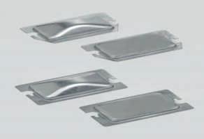
45 Features SpecSeal Power Shield electrical box inserts are used to protect an electrical box and maintain fire-resistance ratings of wall assemblies when the horizontal separation between metallic boxes on opposite sides of the wall is less than 24. The intumescent insert is designed to install inside the box, directly against the back wall. SpecSeal Power Shield expands a minimum of 24 times its original size, when exposed to high temperatures or flames, to quickly seal off the passage of fire and smoke. Simple to install. SpecSeal Power Shields are sized to fit typical outlet boxes and feature an adhesive strip on the back of the pad to ensure adhesion to the back of the electrical box. Installs quickly with no mess/residue. The low profile design maximizes the area inside the electrical box. Water resistant - no soluble or hygroscopic ingredients. Firestop Pads UPC/Part Number Catalog Number Size & Description Box Qty EP /4 x 3 3 /4 x 1 /8 for 4 Square Box EP /2 x 4 1 /2 x 1 /8 for 4 11 /16 Square Box 20 Properties Electrical Box Inserts Color: Red Weight: EP lbs. (0.036 kg) EP lbs. (0.045 kg) Volume: EP cu in. (28.8 cu cm.) EP cu in. (41.0 cu cm.) Expansion Begins: 350 F (177 C) Expansion Range: 350 F to >1000 F (177 C C) Volume Expansion: 16 to 24X (free expansion) In Service Temperature: <130 F (54 C) Oven Aging: No Change (60 C)* Humidity Exposure: No Change (60 C, 98% R.H.)* Shelf Life: No Limit STC Rating: 64 * Evaluation of physical properties and total expansion. Accessories SpecSeal is a registered trademark of Specified Technologies Inc. Basic Ruff-IN = 3-5 day lead-time for quantities of 1000 or less. 45

46 Metal Protector Plates BPS1 BPS2 Features Protects box contents from drywall mud, paint and debris. Protector plates provided with all wiring device assemblies. Can be installed on plaster rings with or without preinstalled wiring devices. Protects pre-installed wiring devices from damage during drywall installation. Improved design transmits force of drywall installation to the plaster ring - not the wiring device. Domed plate for toggle switches allows for clearance between the plate and switch, and eliminates scratching of the devices. Two protector plates are required for two device plaster rings. BPR1 BPR2 Accessories UPC/Part Number Catalog Number Devices Plaster Ring Style BPR1 Receptacles, GFCI, Decorator, None One Device BPS1 Toggle Switches One Device BPR2 Receptacles, GFCI, Decorator, None Two Device BPS2 Toggle Switches Two Device 50 Box Qty Basic Ruff-IN = 3-5 day lead-time for quantities of 1000 or less. 46


47 Adjustable & Standard Plaster Rings Features Adjustable plaster ring can be used with 4 square, 2 1 /8 deep boxes and fits a range of drywall thicknesses. Single gang plaster ring can be used in combination with Cooper B-Line s BB4-23 series, BB73 Series, BB8-16 Series, BFM Series, and BB2-16 Series. It is provided with a 3 /4 raise and can be adjusted to a 1 1 /2 raise. Two gang plaster ring can be used in combination with Cooper B-Line s BB2-16 Series and BB73 Series. It is provided with 5 /8 raise and can be adjusted to a 1 1 /2 raise. The plaster ring can be adjusted after sheet rock, mud, or tile is installed without removing the wiring devices. B1AJ B2AJ B3AJ BRAJ UPC/Part Number Catalog Number Description Depth Box Qty Ruff-In Code B1AJ One Device Adjustable Ring 3/4-1 1 /2 25 1AJ B2AJ Two Device Adjustable Ring 5/8-1 1 /2 25 2AJ B3AJ Three Device Adjustable Ring 3/4-1 1 /2 25 3AJ BRAJ Round Device Adjustable Ring 3/4-1 1 /2 25 RAJ One Device Two Device Round Plaster Rings Plaster Ring One Device Two Device Round Size Ruff-In Code Ruff-In Code Ruff-In Code Accessories Stock Components Non Stock Components 1 /4 raise R04 1 /2 raise R08 5 /8 raise R10 3 /4 raise R12 1 raise R /4 raise R /2 raise R24 2 raise R32 47
 1 /2, (4) 1 /2 & 3 /4 E (2) 1 /2, (2) 1 /2 & 3 /4 E 4D TP-436 4 Square 2 1 /8 30.3 in 3 (8) 1 (2) 1 /2, (2) 1 /2 & 3 /4 E 436 TP-404 4 Square 1 1 /2 22.")
 1 /2 & 3 /4 E, (4) 1 /2, (4) cable (1) 1 /2 431 TP-563 4 11 /16 Square 2 1 /8 42.0 in 3 (6) 1 /2, (6) 1 /2 & 3 /4 E (3) 1 /2, (2) 3 /4 5D TP-560 4 11 /16 Square 2 1 /8 42.")
48 Electrical Boxes TP-403 TP-436 TP-404 TP-432 TP-563 TP-560 TP-431 TP-548 TP-554 Part Number Size Depth Capacity Side KO Bottom KO Ruff-In Code Accessories TP Square 2 1 / in 3 (8) 1 /2, (4) 1 /2 & 3 /4 E (2) 1 /2, (2) 1 /2 & 3 /4 E 4D TP Square 2 1 / in 3 (8) 1 (2) 1 /2, (2) 1 /2 & 3 /4 E 436 TP Square 1 1 / in 3 (8) 1 /2, (4) 1 /2 & 3 /4 E (2) 1 /2, (2) 1 /2 & 3 /4 E 4 TP Square 2 1 / in 3 (8) 3 /4 (2) 1 /2, (2) 1 /2 & 3 /4 E 432 TP Square 2 1 / in 3 (2) 1 /2 & 3 /4 E, (4) 1 /2, (4) cable (1) 1 /2 431 TP /16 Square 2 1 / in 3 (6) 1 /2, (6) 1 /2 & 3 /4 E (3) 1 /2, (2) 3 /4 5D TP /16 Square 2 1 / in 3 (8) 1 (3) 1 /2, (2) 3 /4 560 TP /16 Square 1 1 / in 3 (8) 1 /2, (4) 3 /4 (3) 1 /2, (2) 3 /4 5 TP /16 Square 2 1 / in 3 (8) 3 /4 (3) 1 /2, (2) 3 /4 554 Stock Components Non Stock Components 48
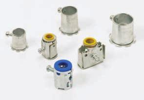
49 Cable & Conduit Connectors Stock Components Non Stock Components QLK50S SSBC50 QLK50D SSBC75 QLK75S SSBC100 MC Cable Connectors Part Number Ruff-In Code Size QLK50S A 1 /2 Single QLK50D B 1 /2 Duplex QLK75S C 3 /4 Single EMT Conduit Connectors Part Number Ruff-In Code Size SSBC50 D 1 /2 SSBC75 E 3 /4 SSBC100 F 1 MC Cable Connectors Accessories 38AST Part Number Ruff-In Code Size 38AST P 1 /2 Single 40AST Q 3 /4 Single 40AST 49
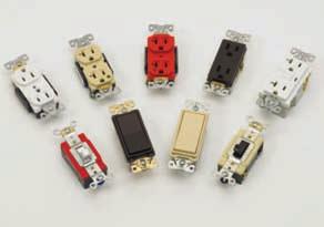
50 Reference Data - Wiring Devices Item Description & Color Ruff-In Stock Stock Code Code Standard Duplex Receptacles 5252W shown 15 Amp 5252B Receptacle - 15 Amp Industrial Grade, Brown DAB 5252V Receptacle - 15 Amp Industrial Grade, Ivory DAV 5252W Receptacle - 15 Amp Industrial Grade, White DAW 5262CB Receptacle - 15 Amp Industrial Grade, Brown DBB 5262CV Receptacle - 15 Amp Industrial Grade, Ivory DBV 5262CW Receptacle - 15 Amp Industrial Grade, White DBW IG5262RN Receptacle - 15 Amp Industrial Grade, Isolated Ground, Orange DGO 5262B Receptacle - 15 Amp Industrial Grade, Brass Strap, Brown EAB 5262V Receptacle - 15 Amp Industrial Grade, Brass Strap, Ivory EAV 5262W Receptacle - 15 Amp Industrial Grade, Brass Strap, White EAW CR5262B Receptacle - 15 Amp Construction Spec. Grade, Brown KBB CR5262V Receptacle - 15 Amp Construction Spec. Grade, Ivory KBV CR5262W Receptacle - 15 Amp Construction Spec. Grade, White KBW BR15B Receptacle - 15 Amp Commercial Grade, Brown DEB BR15V Receptacle - 15 Amp Commercial Grade, Ivory DEV BR15W Receptacle - 15 Amp Commercial Grade, White DEW Tamper Resistant Duplex Receptacles 15 Amp TRBR15A Tamper Resistant Receptacle - Commercial Grade, Almond TAA TRBR15B Tamper Resistant Receptacle - Commercial Grade, Brown TAB TRBR15BK Tamper Resistant Receptacle - Commercial Grade, Black TAK TRBR15GY Tamper Resistant Receptacle - Commercial Grade, Gray TAG TRBR15L Tamper Resistant Receptacle - Commercial Grade, Light Almond TAL TRBR15V Tamper Resistant Receptacle - Commercial Grade, Ivory TAV TRBR15W Tamper Resistant Receptacle - Commercial Grade, White TAW Standard Duplex Receptacles IG5362RN shown 20 Amp 5352B Receptacle - 20 Amp Industrial Grade, Brown DCB 5352V Receptacle - 20 Amp Industrial Grade, Ivory DCV 5352W Receptacle - 20 Amp Industrial Grade, White DCW 5362CB Receptacle - 20 Amp Industrial Grade, Brown DDB 5362CV Receptacle - 20 Amp Industrial Grade, Ivory DDV 5362CW Receptacle - 20 Amp Industrial Grade, White DDW IG5362RN Receptacle - 20 Amp Industrial Grade, Isolated Ground, Orange DHO 5362B Receptacle - 20 Amp Industrial Grade, Brass Strap, Brown EBB 5362V Receptacle - 20 Amp Industrial Grade, Brass Strap, Ivory EBV 5362W Receptacle - 20 Amp Industrial Grade, Brass Strap, White EBW CR5362B Receptacle - 20 Amp Construction Spec. Grade, Brown KAB CR5362V Receptacle - 20 Amp Construction Spec. Grade, Ivory KAV CR5362W Receptacle - 20 Amp Construction Spec. Grade, White KAW BR20B Receptacle - 20 Amp Commercial Grade, Brown DFB BR20V Receptacle - 20 Amp Commercial Grade, Ivory DFV BR20W Receptacle - 20 Amp Commercial Grade, White DFW Accessories Tamper Resistant Duplex Receptacles Hospital Grade Duplex Receptacles 8200V shown 20 Amp 15 Amp TRBR20A Tamper Resistant Receptacle - Commercial Grade, Almond TBA TRBR20B Tamper Resistant Receptacle - Commercial Grade, Brown TBB TRBR20BK Tamper Resistant Receptacle - Commercial Grade, Black TBK TRBR20GY Tamper Resistant Receptacle - Commercial Grade, Gray TBG TRBR20L Tamper Resistant Receptacle - Commercial Grade, Light Almond TBL TRBR20V Tamper Resistant Receptacle - Commercial Grade, Ivory TBV TRBR20W Tamper Resistant Receptacle - Commercial Grade, White TBW 8200B Receptacle - 15 Amp Hospital Grade, Nickel Plated Brass Strap, Brown FAB 8200V Receptacle - 15 Amp Hospital Grade, Nickel Plated Brass Strap, Ivory FAV 8200W Receptacle - 15 Amp Hospital Grade, Nickel Plated Brass Strap, White FAW 8200HB Receptacle - 15 Amp Hospital Grade, Steel Strap, Brown FBB 8200HV Receptacle - 15 Amp Hospital Grade, Steel Strap, Ivory FBV 8200HW Receptacle - 15 Amp Hospital Grade, Steel Strap, White FBW IG8200RN Receptacle - 15 Amp Hospital Grade, Isolated Ground, Orange FFO 8300HV shown 20 Amp 8300B Receptacle - 20 Amp Hospital Grade, Nickel Plated Brass Strap, Brown FCB 8300V Receptacle - 20 Amp Hospital Grade, Nickel Plated Brass Strap, Ivory FCV 8300W Receptacle - 20 Amp Hospital Grade, Nickel Plated Brass Strap, White FCW 8300HB Receptacle - 20 Amp Hospital Grade, Steel Strap, Brown FDB 8300HV Receptacle - 20 Amp Hospital Grade, Steel Strap, Ivory FDV 8300HW Receptacle - 20 Amp Hospital Grade, Steel Strap, White FDW IG8300RN Receptacle - 20 Amp Hospital Grade, Isolated Ground, Orange FEO Stock Components Non Stock Components 50
51 Reference Data - Wiring Devices Item Description & Color Ruff-In Stock Stock Code Code Decorator Receptacles 6252B Decorator Receptacle - 15 Amp Commercial Grade, Brown GAB 6252V Decorator Receptacle - 15 Amp Commercial Grade, Ivory GAV 6252W Decorator Receptacle - 15 Amp Commercial Grade, White GAW 15 Amp 6252B shown 6352B Decorator Receptacle - 20 Amp Commercial Grade, Brown GBB 6352V Decorator Receptacle - 20 Amp Commercial Grade, Ivory GBV 6352W Decorator Receptacle - 20 Amp Commercial Grade, White GBW 20 Amp Decorator Receptacles 6352W shown TR6352A Commercial Grade, Almond TCA TR6352B Commercial Grade, Brown TCB TR6352BK Commercial Grade, Black TCK TR6352GY Commercial Grade, Gray TCG TR6352LA Commercial Grade, Light Almond TCL TR6352V Commercial Grade, Ivory TCV TR6352W Commercial Grade, White TCW 20 Amp Tamper Resistant Decorator Receptacles VGFH15B GFCI - 15 Amp Hospital Grade, Brown JAB VGFH15V GFCI - 15 Amp Hospital Grade, Ivory JAV VGFH15W GFCI - 15 Amp Hospital Grade, White JAW VGF15B GFCI - 15 Amp Commercial Grade, Brown GCB VGF15V GFCI - 15 Amp Commercial Grade, Ivory GCV VGF15W GFCI - 15 Amp Commercial Grade, White GCW 15 Amp VFG15W shown GFCI Receptacles TRVG15A Tamper Resistant - GFCI - Commercial Grade, Almond TGA TRVG15B Tamper Resistant - Commercial Grade, Brown TGB TRVG15BK Tamper Resistant - Commercial Grade, Black TGK TRVG15GY Tamper Resistant - Commercial Grade, Gray TGG TRVG15LA Tamper Resistant - Commercial Grade, Lt Almond TGL TRVG15V Tamper Resistant - Commercial Grade, Ivory TGV TRVG15W Tamper Resistant - GFCI - Commercial Grade, White TGW 15 Amp Tamper Resistant GFCI Receptacles VGFH20B GFCI - 20 Amp Hospital Grade, Brown JBB VGFH20V GFCI - 20 Amp Hospital Grade, Ivory JBV VGFH20W GFCI - 20 Amp Hospital Grade, White JBW VGF20B GFCI - 20 Amp Commercial Grade, Brown GDB VGF20V GFCI - 20 Amp Commercial Grade, Ivory GDV VGF20W GFCI - 20 Amp Commercial Grade, White GDW TRVG20A Tamper Resistant - GFCI - Commercial Grade, Almond THA TRVG20B Tamper Resistant - GFCI - Commercial Grade, Brown THB TRVG20BK Tamper Resistant - GFCI - Commercial Grade, Black THK TRVG20GY Tamper Resistant - GFCI - Commercial Grade, Gray THG TRVG20LA Tamper Resistant - GFCI - Commercial Grade, Lt Almond THL TRVG20V Tamper Resistant - GFCI - Commercial Grade, Ivory THV TRVG20W Tamper Resistant - GFCI - Commercial Grade, White THW 20 Amp 20 Amp VGF20W shown GFCI Receptacles Tamper Resistant GFCI Receptacles Accessories Stock Components Non Stock Components 51
52 Reference Data - Wiring Devices Item Description & Color Ruff-In Stock Stock Code Code Toggle Switches CSB115B shown 15 Amp 1201B Single Pole Toggle Switch - 15 Amp Industrial Grade, Brown ADB 1201V Single Pole Toggle Switch - 15 Amp Industrial Grade, Ivory ADV 1201W Single Pole Toggle Switch - 15 Amp Industrial Grade, White ADW 1202B Double Pole Toggle Switch - 15 Amp Industrial Grade, Brown AHB 1202GY Double Pole Toggle Switch - 15 Amp Industrial Grade, Gray AHG 1202V Double Pole Toggle Switch - 15 Amp Industrial Grade, Ivory AHV 1202W Double Pole Toggle Switch - 15 Amp Industrial Grade, White AHW CSB115B Single Pole Toggle Switch - 15 Amp Commercial Grade, Brown BDB CSB115V Single Pole Toggle Switch - 15 Amp Commercial Grade, Ivory BDV CSB115W Single Pole Toggle Switch - 15 Amp Commercial Grade, White BDW CSB215B Double Pole Toggle Switch - 15 Amp Commercial Grade, Brown BGB CSB215GY Double Pole Toggle Switch - 15 Amp Commercial Grade, Gray BGG CSB215V Double Pole Toggle Switch - 15 Amp Commercial Grade, Ivory BGV CSB215W Double Pole Toggle Switch - 15 Amp Commercial Grade, White BGW 1203B 3 Way Toggle Switch - 15 Amp Industrial Grade, Brown AEB 1203V 3 Way Toggle Switch - 15 Amp Industrial Grade, Ivory AEV 1203W 3 Way Toggle Switch - 15 Amp Industrial Grade, White AEW CSB315B 3 Way Toggle Switch - 15 Amp Commercial Grade, Brown BEB CSB315V 3 Way Toggle Switch - 15 Amp Commercial Grade, Ivory BEV CSB315W 3 Way Toggle Switch - 15 Amp Commercial Grade, White BEW 2221W shown 20 Amp 2221B Single Pole Toggle Switch - 20 Amp Industrial Grade, Brown AAB 2221V Single Pole Toggle Switch - 20 Amp Industrial Grade, Ivory AAV 2221W Single Pole Toggle Switch - 20 Amp Industrial Grade, White AAW 2222B Double Pole Toggle Switch - 20 Amp Industrial Grade, Brown AGB 2222GY Double Pole Toggle Switch - 20 Amp Industrial Grade, Gray AGG 2222RD Double Pole Toggle Switch - 20 Amp Industrial Grade, Red AGR 2222V Double Pole Toggle Switch - 20 Amp Industrial Grade, Ivory AGV 2222W Double Pole Toggle Switch - 20 Amp Industrial Grade, White AGW CSB120B Single Pole Toggle Switch - 20 Amp Commercial Grade, Brown BAB CSB120V Single Pole Toggle Switch - 20 Amp Commercial Grade, Ivory BAV CSB120W Single Pole Toggle Switch - 20 Amp Commercial Grade, White BAW CSB220B Double Pole Toggle Switch - 20 Amp Commercial Grade, Brown BHB CSB220GY Double Pole Toggle Switch - 20 Amp Commercial Grade, Gray BHG CSB220V Double Pole Toggle Switch - 20 Amp Commercial Grade, Ivory BHV CSB220W Double Pole Toggle Switch - 20 Amp Commercial Grade, White BHW 2223B 3 Way Toggle Switch - 20 Amp Industrial Grade, Brown ABB 2223V 3 Way Toggle Switch - 20 Amp Industrial Grade, Ivory ABV 2223W 3 Way Toggle Switch - 20 Amp Industrial Grade, White ABW CSB320B 3 Way Toggle Switch - 20 Amp Commercial Grade, Brown BBB CSB320V 3 Way Toggle Switch - 20 Amp Commercial Grade, Ivory BBV CSB320W 3 Way Toggle Switch - 20 Amp Commercial Grade, White BBW Accessories Decorator Switches 7601V shown 7621B shown 15 Amp 20 Amp 7601B Single Pole Decorator Switch - 15 Amp Commercial Grade, Brown CDB 7601V Single Pole Decorator Switch - 15 Amp Commercial Grade, Ivory CDV 7601W Single Pole Decorator Switch - 15 Amp Commercial Grade, White CDW 7603B 3 Way Decorator Switch - 15 Amp Commercial Grade, Brown CEB 7603V 3 Way Decorator Switch - 15 Amp Commercial Grade, Ivory CEV 7603W 3 Way Decorator Switch - 15 Amp Commercial Grade, White CEW 7621B Single Pole Decorator Switch - 20 Amp Commercial Grade, Brown CAB 7621V Single Pole Decorator Switch - 20 Amp Commercial Grade, Ivory CAV 7621W Single Pole Decorator Switch - 20 Amp Commercial Grade, White CAW 7623B 3 Way Decorator Switch - 20 Amp Commercial Grade, Brown CBB 7623V 3 Way Decorator Switch - 20 Amp Commercial Grade, Ivory CBV 7623W 3 Way Decorator Switch - 20 Amp Commercial Grade, White CBW Stock Components Non Stock Components 52
53 Reference Data - Wiring Devices Item Description & Color Ruff-In Stock Stock Code Code RSF5-A/6005A Fan Speed Control Fully Variable 5A w/adj. trim, Almond RAA RSF5-LA/6005A Fan Speed Control Fully Variable 5A w/adj. trim, Light Almond RAL RSF5-V/6005A Fan Speed Control Fully Variable 5A w/adj. trim, Ivory RAV RSF5-W/6005A Fan Speed Control Fully Variable 5A w/adj. trim, White RAW 5 Amp Switches Rotary Fan Speed Control RFS5-A / 6005V shown TI0671-A/6441A 600W INC SP Dimmer, Almond RCA TI0671-LA/6441LA 600W INC SP Dimmer, Light Almond RCL RSF5-V/6005A 600W INC SP Dimmer, Ivory RCV RSF5-W/6005A 600W INC SP Dimmer, White RCW 600 Watt Toggle Dimmer (non-preset) 6441W shown DI06P-A Slide w/preset 600W INC/MLV SP/3-way Dimmer, Almond RDA DI06P-LA Slide w/preset 600W INC/MLV SP/3-way Dimmer, Light Almond RDL DI06P-BK Slide w/preset 600W INC/MLV SP/3-way Dimmer, Black RDK DI06P-BR Slide w/preset 600W INC/MLV SP/3-way Dimmer, Brown RDB DI06P-V Slide w/preset 600W INC/MLV SP/3-way Dimmer, Ivory RDV DI06P-W Slide w/preset 600W INC/MLV SP/3-way Dimmer, White RDW SI06I-A Full Slide (non-preset) 600W INC/MLV SP Switch, Almond REA SI06I-LA Full Slide (non-preset) 600W INC/MLV SP Switch, Light Almond REL SI06I-V Full Slide (non-preset) 600W INC/MLV SP Switch, Ivory REV SI06I-W Full Slide (non-preset) 600W INC/MLV SP Switch, White REW SI06P-A Full Slide w/preset 600W INC/MLV SP/3-way Dimmer, Almond RFA SI06P-LA Full Slide w/preset 600W INC/MLV SP/3-way Dimmer, Light Almond RFL SI06P-V Full Slide w/preset 600W INC/MLV SP/3-way Dimmer, Ivory RFV SI06P-W Full Slide w/preset 600W INC/MLV SP/3-way Dimmer, White RFW 600 Watt DI06P-W shown SI06I-W shown Decorator Dimmer SI06P-LA shown 150 degrees, single pole, 900 sq. ft. fluorescent: 6105V (2) 30W min. 400W 120V. Rapid Start Incandescent: RBV 120V, Motor: 1 /8HP A2 120V, Ivory 150 degrees, single pole, 900 sq. ft. fluorescent: 6105W (2) 30W min. 400W 120V. Rapid Start Incandescent: RBW 120V, Motor: 1 /8HP A2 120V, White 6105W shown Occupancy Sensor Accessories Stock Components Non Stock Components 53


54 ArrowLink Modular Wiring Devices The benefits of modular devices foryourentire job, not just a portion. ArrowLink Modular Wiring Devices change the game for electrical installers by providing an unequalled breadth of devices that offer greater speed and consistency to lower installation costs on the job site. ArrowLink maximizes labor savings: Breadth of line provides efficiency in more applications Modular connections increase trim-out speed more than 2 to 1 Consistent connections eliminate mis-wiring and reduce call-backs Modular Decorator & Toggle Switches Modular TVSS Receptacles Modular Straight Blade Single & Duplex Receptacles Connector leads are prepped, stripped and ready to wire External connections provide job site flexibility Reduces number of trim-out installers required Narrows learning curve for apprentice labor Modular GFCIs, Tamper Resistant GFCIs Modular Isolated Ground Receptacles ArrowLink Receptacle Modular Plug & Connector Accessories Devices that arrive the way you want! ArrowLink features bulk packaging designed with the contractor in mind. 1 All devices are shipped in convenient recyclable bulk pack cartons All packaging made of 100% recycled material Packaging sizedfor easy room-to-room transport No inner packaging speeds installation, eliminates waste, and reduces clean-up at the endof the job Incorporated honeycomb dividers allow a consistent package size across our entire ArrowLink product line for efficient shipping 54


55 ArrowLink Modular Wiring Devices The ArrowLink Advantage ArrowLink is designed to help you complete a job quickly and cost effectively. The breadth of line combined with unique installation flexibility and safety features provide a complete job solution. Leaded ArrowLink plug preserves the structural integrity of the base wiring device Plug and connector design provides first make/last break grounding connection Terminal safety barriers provide insulation from conductive surfaces Audible click indicates a secure connection Modular Receptacle Patent-pending ArrowLink modular plugs and connectors provide high quality circuit connections while reducing overall installation time. Plug leads #12 AWG stranded copper Polybag connector cover shields contacts from paint and drywall mud Pre-wired modular switches available in both toggle anddecorator styles for 120V or 277V #12 AWG wire leads color coded for your 277V applications; see ordering info for 277V conductor color options Modular Switch Quality, Dependability and Versatility Connector leads #12 AWG, pre-stripped& available in solidor stranded copper Unique switch andreceptacle configurations will not inter-mate for added safety ArrowLink wiring devices can easily be convertedfor standard installation Accessories Slim profile andvertical wire orientation of device andconnector assures ease of installation Clearly marked, consistent pre-wiredconfigurations eliminatemis-wiring of devices 2 55
BLFRITRI-09R. Ruff-IN. Pre-Fab Systems
 BLFRITRI-09R Ruff-IN Pre-Fab Systems Table of Contents Table of Contents.................................................... 2 Ruff-IN & Total Ruff-IN Service Advisors....................... 3 Explanation
Communication & Low Voltage. Communication & Low Voltage
 145 Communication & low Voltage Cable Supports cable ties up to 9 /32" wide from flanges 1 /16" to 3 /4" thick. 8" cable tie included. Simply installed with a hammer. BE Series BF Series 78101119970 BE-2-4-CT2
Switch & Outlet Boxes Technical Data
 Switch & Outlet Boxes Technical Data General Information: A box, with or without a bracket or bar hanger, intended for support of a fixture/luminaire weighing 50 lbs. or less is marked FOR FIXTURE/ LUMINAIRE
4 Square Partition Square Cut Tile Wall 2 Gang Cover 2 1/8 Deep 1/2 to 1 RSD
 3804 South Street 75964-7263, TX Nacogdoches Phone: 936-569-7941 Fax: 936-560-4685 TP862 4IN SQ Box Partition Cooper Crouse-Hinds Catalog Number Manufacturer Weight per unit Product Category Features Material
SHELVING PRODUCTS. Maximize Your Storage Space
 SHELVING PRODUCTS Maximize Your Storage Space SHELVING UNITS Pre-engineered sections are 36, 42, and 48 wide and 84, 96 and 120 high, with shelves adjustable on 1-1/2 centers. For double row, back-to-back
Steel Outlet Boxes 4 11 /16" Welded
 Steel Outlet Boxes 4 11 /16" Welded Steel Outlet Boxes Features & Benefits Ideal for exposed work applications, providing an easy method for the installation of electrical devices (switches, receptacles,
FAS power pre-fabricated. catalog
 2011 FAS power pre-fabricated wiring assemblies catalog FAS Power reduces labor costs a minimum of 50% Easy to order Easier to install If you are constructing a hospital, condominium complex, office building
4-11/16 Square Boxes. With Conduit Knockouts OB/SB-1. 4SJ-3/4 1-1/2 Deep, Welded. 4SJ-EK 1-1/2 Deep, Welded. 4SJD-3/4 2-1/8 Deep, Welded
 4-11/16 Square Boxes With Conduit Knockouts 4SJ-3/4 1-1/2 Deep, Welded 4SJ-EK 1-1/2 Deep, Welded 4SJD-3/4 4SJD-EK 4SJD-3/4-1 4SJD-1 4SJD-1-1/4 Number Depth Cubic Inch Knockout Description Wt. Lbs. Std.
UL Listed TP408. KNOCKOUTS Cat. # Bracket Description Sides Bottom Unit Qty. Wt. Lbs. Per 100 TP408 Drawn 12 1 /2" 5 1 /2" 50 61
 4" SQUARE OUTLET BOXES AND COVERS Features: Applications: For use with conduit Can be ceiling mounted to be used as a junction box or to mount lighting fixtures Available in red for fire alarm applications
561LVB 561LVB 4 Oct Box W/Bracket. Features. Dimensions and Weight. Description. Manufacturer Information. Taxonomies, Classifications, and Categories
 3804 South Street 75964-7263, TX Nacogdoches Phone: 936-569-7941 Fax: 936-560-4685 561LVB 561LVB 4 Oct Box W/Bracket Appleton/Oz Gedney Catalog Number Manufacturer Description Weight per unit Product Category
Floor Box Product Catalog
 Floor Box Product Catalog FLOOR BOX ASSEMBLIES AND ACCESSORIES FOR RESIDENTIAL & COMMERCIAL CONSTRUCTION *INCLUDES THE NEW SLIDERBOX FLOOR BOX Allied Moulded Floor Boxes Adjustable Single Gang Floor Box
PRODUCT BROCHURE. Steel City fire-rated poke-through systems
 PRODUCT BROCHURE Steel City fire-rated poke-through systems Table of contents 002 Fire-rated poke-through systems 004 009 FPT4 flush series 010 FPT3 flush series 011 012 FPT flush series 013 014 FFPT4
ACDelco CONNECTION - The Right Parts at Your Fingertips
 2016 Special Edition 1 2016 SPECIAL EDITION ACDelco CONNECTION - The Right Parts at Your Fingertips Welcome to a special issue of ACDelco Insider one devoted exclusively to CONNECTION and how to make the
Acoustical. Pages Watch for this icon for compatibility with new taller grid profile. Ph:
 Watch for this icon for compatibility with new taller grid profile Pages 175-190 Sold by: http://www.twacomm.com Toll Free: (877) 892-2666 175 Lay In And Troffer Light Fixture Support Clips The original
Kindorf Stainless Steel Modular Framing System
 In this section... Kindorf Stainless Steel Modular Framing System Kindorf Stainless Steel Modular Framing System Overview... 6 Channels, Straps and Clamps... 7 Channel Fittings and Hardware...8 44 Overview
Put the Power in Your Hands
 Put the Power in Your Hands StarlineTrack Busway... STARLINE Track Busway is quickly becoming the industry standard for power distribution systems. Introduced in 1988, this innovative system is a modular,
Bulb Depot Woodland Park NJ UNIT QTY. UNIT COST TOTAL COST. foot 300 $0.39 $ each 100 $1.45 $ each 100 $1.25 $125.00
 1 1/2" EMT 2 1/2" EMT Parallel Beam Clamps 3 1/2" EMT Right Angle Beam Clamps 4 1/2" EMT Set Screw Connectors 5 1/2" EMT Set Screw Couplings 6 1/2" EMT One Hole Straps 7 1/2" EMT Unistrut Straps 8 1/2"
Cable Tray CT2D-18. Tray2Day SM. cable tray service program
 Cable Tray CT2D-18 Tray2Day SM cable tray service program * * At, we believe that power is a fundamental part of just about everything people do. That s why we re dedicated to helping our customers s find
LINEAR LED. Delivering Quality Light Better LOW BAY HIGH BAY WET LOCATION EDGE LIT PANELS 2' HIGH BAY NOW IN STOCK INTRODUCING
 LINEAR LED LOW BAY HIGH BAY WET LOCATION EDGE LIT PANELS Delivering Quality Light Better INTRODUCING 2' HIGH BAY NOW IN STOCK TABLE OF CONTENTS Linear LED High Bay... Pages 6-9 2' Narrow High Bay... pg
For our PAC Brackets - Contact us to request one of our Market Specific Catalogs!
 We believe in our product, and so do many large Municipal Fire Departments around North America! Install PAC tool boards and brackets on one of your engines. You ll soon learn the simplicity and value
Ideal for surface mounting
 One-Piece Surface Steel Raceway V500 /V700 /700H Steel Raceway Ideal for surface mounting small amounts of electrical wiring or communication cables. These rugged raceways offer a low profile appearance
COMPACT BUSWAY 40 & 60 AMP HOUSING
 40 & 60 AMP HOUSING B40 & HOUSING Each Track Busway housing section consists of an extruded aluminum housing with an insulated strip containing copper conductors mounted on the top interior wall. The aluminum
MADE FOR THE TRADE! LECTRIC 555 SERIES & 855GX
 MADE FOR THE TRADE! LECTRIC 555 SERIES & BENDERS 855GX The next-generation electric conduit benders are here. 555 Series & 855GX Both the 855GX and the 555 series benders have been completely re-engineered
underfloor 49 UFC UFC 50 FAS P 50 UFCN 51 UC C DF 54 UFS 55 UFFS 56 UFS Cablofil cable management UNDER FLOOR SUPPORT CLAMP kit
 underfloor 49 UFC 550 UNDER FLOOR SUPPORT CLAMP kit 49 UFC UNDER FLOOR SUPPORT CLAMP 50 FAS P FAS PROFILE 50 UFCN UNDER FLOOR CLAMP 51 UC 50 CABLE TRAY STANDOFF 51 C 50 UNDER FLOOR ATTACHMENT 52 fas l
UL Listed TP408. KNOCKOUTS Cat. # Bracket Description Sides Bottom Unit Qty. Wt. Lbs. Per 100
 4" SQUARE OUTLET BOXES AND COVERS Features: Applications: For use with conduit Available in red for fire alarm applications Ideal for exposed work applications, providing an easy method for the installation
KNOCKOUTS Cat. # Bracket Plastic Clamp Conduit Cable Unit Qty. Wt. Lbs. Per 100 TP100 TP104 TP106 TP114
 1" DEEP - NON-GANGABLE - 6.5 CUBIC INCH CAPACITY 1 15 /16" WIDE x 3 3 /4" LONG TP101 TP103 Cat. # Bracket Plastic Clamp Conduit Cable Unit Qty. Wt. Lbs. Per 100 TP101 "S" No 1 1 /2" 2 25 38 TP103 "S" Yes
WEIGHT DISTRIBUTION SYSTEMS
 Cequent has been the leader in weight distributing systems for 60 years. Over those years, much has changed within the industries we serve. Tow vehicles and their frames have been made lighter while the
Channel Cable Tray - Accessories & Fittings
 hannel able Tray - Straight Sections E-1 -Line series able Tray Systems hannel able Tray - ccessories & Fittings How The Service dvisor Works We know that your time is important! That s why the color-coding
Pronto Changeable Copy
 Pronto s Pronto Changeable Copy Rigid.080 panels - no fly away letters Patented panel design prevents scratches UV inks have no harmful VOCs Molded feet keep panels from sticking in track Ships in 1 business
WIRE BASKET TRAY CANADIAN ELECTRICAL RACEWAYS INC.
 CANADIAN ELECTRICAL RACEWAYS INC. WIRE BASKET TRAY Made of heavy-gauge zinc plated wire mesh, CER basket tray is ideal for your commercial or industrial cable management project. A full range of cable
Nonmetallic Thermoplastic Boxes Wall/Ceiling Boxes with Soft Box Characteristics
 Nonmetallic Thermoplastic es Wall/Ceiling es with Soft Characteristics flexbox Material & Labor Saving Features Allied Moulded flexbox switch and outlet boxes are molded of engineering grades of nonmetallic
Stainless Steel Continuous Hinges
 TABLE OF CONTENTS A ANSI Standards... 2 C Cancellation Notification... 2 Concealed Electric Through-Wire... 3 Custom Hole Pattern... 2 Custom Length Hinges... 2 D Dust Free Bearings... 3 Dutch Door Hinges...
SERIES 4LBV-NF Flush Mount Lumen Bridgelux LED Lensed Downlight
 APPLICATION These high-lumen fixtures are ideally suited for lobbies, auditoriums and many other applications with high ceilings, where superior light output is needed. Suitable for commercial, retail,
Spring Steel Fasteners
 BB15 BB10-3 BB423-208 BB10L BCH32 BCH32X BCH32-F3 KIT BCH32-U-5-8 BCH32-A28 BW2-CT2 BCH32-3S BCH32-F4 BCH32-C2 BCH32-W2 BRS-32A BCH32-SC4 BCH-32-4T-C1 BCH-32-4T-A6 BR-32-4T-U-5-8 BR-32-4T-W2 233 Cooper
Cable Festoon Systems - For Moving Machinery
 Cable Festoon Systems - For Moving Machinery CONDUCTIX offers a comprehensive range of Cable Festoon Systems to power moving machinery. Our festoon systems are ideal for supporting, protecting, and managing
Cable Festoon Systems - For Moving Machinery
 Cable Festoon Systems - For Moving Machinery CONDUCTIX offers a comprehensive range of Cable Festoon Systems to power moving machinery. Our festoon systems are ideal for supporting, protecting, and managing
Installing a Downstream Distribution Panelboard
 Job Sheet 5 Installing a Downstream Distribution Panelboard OBJECTIVE To install a downstream distribution panelboard (DDP) on the Mobile Workstation. To mechanically and electrically connect the DDP to
Conduit and Wire. Wire and Cable Whips. Bus Duct, Cable Trays, Overhead or Under Floor Raceways, Strut or Channel Systems
 Conduit and Wire Must be scrapped whenever reconfiguration of the electrical layout is needed. Many runs may be needed for applications with a high volume or high density of electrical loads. It is labor
Innovations. Supplement to Eldon Product Catalogue
 Innovations Supplement to Eldon Product Catalogue Table of contents Quick fixation baying brackets... 4 Mounting plate brackets... 6 Profile system... 8 Side panel improvement... 10 Easy fixation with
MODEL 8682 SUREFLOW ADAPTIVE OFFSET CONTROLLER
 MODEL 8682 SUREFLOW ADAPTIVE OFFSET CONTROLLER INSTALLATION INSTRUCTIONS WARNING: The Model 8682 Adaptive Offset Controller must be wired to 24 VAC only. Wiring the unit to 110 VAC will cause serious unit
EQUIPMENT PROTECTION
 Contractor Specifier s Guide EQUIPMENT PROTECTION WWW.PENTAIRPROTECT.COM/HOFFMAN Volume 8 Hoffman Has You Covered From utility junctions to protecting relays, contactors and wire, Hoffman has you covered.
Florham Park, NJ USA Call (ASCO) for sales or service
 for sales or service") Operator s Manual 4000 Series ATS Automatic Open-Transition Transfer Switches D design 30 230A, J design 260 600A, H-design 800 1200A, G-design 1600 4000A, F-design 4000A DANGER is used in this manual
Operator s Manual 4000 Series ATS Automatic Open-Transition Transfer Switches D design 30 230A, J design 260 600A, H-design 800 1200A, G-design 1600 4000A, F-design 4000A DANGER is used in this manual
PART B BRAND SPECIFIC MANUAL
 SPA OWNER S MANUAL IMPORTANT SAFETY INSTRUCTIONS PART B BRAND SPECIFIC MANUAL ELECTRICAL CONNECTION KEYPAD OPERATION 200 Series 200-M-B-16 Read in conjunction with Part A General Manual to form a complete
BASKET TRAY SYSTEM WITH PREFAB FITTINGS
 BASKET TRAY SYSTEM WITH PREFAB FITTINGS SM Cut Time, Not Corners with QuickTurn Prefab Fittings QuickTurn prefab fittings save you time and money. Cutting fittings for basket tray installation is labor-intensive
Product Selection Guide
 WWW.OMEGASCAFFOLDING.COM E-Mail :- info@omegascaffolding.com Product Selection Guide OMEGA SCAFFOLDING SUPPLY INC Reaching the height of excellence Table of Contents About us Frames Braces & Pins Planks
Series 2000 Inline Helical Gear Drives & Gear Motors
 A L T R A I N D U S T R I A L M O T I O N Series 2000 Inline Helical Gear Drives & Gear Motors INTRODUCING NEW GEARING SOLUTIONS FROM BOSTON GEAR This well recognized Altra Industrial Motion brand has
Phase Technology PPA-70Xi Pour Point Analyzer
 Phase Technology PPA-70Xi Pour Point Analyzer About Phase Technology Expertise: Design & manufacture of analyzers to test cloud, pour and freeze point Cold Flow is All We Do! Scientific Background: 29
CIRRUS SUSPENSION WALL WASH WITH REMOTE POWER, END FEED
 Adjustable Max. 5 ft. Description Cirrus Suspension Wall Wash with Remote 24VDC power supply (sold separately) is a linear LED fixture that offers a wall wash lens for a smooth and uniform beam spread.
DELIVERING QUALITY LIGHT BETTER. Linear LED LOW BAY HIGH BAY WET LOCATION
 DELIVERING QUALITY LIGHT BETTER 2017 Linear LOW BAY HIGH BAY WET LOCATION Table of Contents Linear High Bay Pages 6-15 Linear Wet Location Pages 16-26 pg 6 pg 7 pg 8 pg 17 pg 18 pg 19 pg 20 9,000 lumens
Spring Steel Fasteners
 Conduit Supports 1 Available for 3/8 No tools needed! in. through 2 in. Finger friendly trade sizes for design! EMT, flexible conduit and MC/ AC cable Available with either a plain hole for 1/4 in. bolt
STRONGER THAN STEEL. interior and exterior framing
 ROUGH OPENINGS PRODUCT CATALOG STRONGER SM THAN STEEL. interior and exterior framing rough openings ROUGH OPENINGS M A D E E A S Y. Rough openings have always been a challenge on the jobsite. At ClarkDietrich,
STANDARD SHAPES TROLLEY PARTS MANUAL
 STANDARD SHAPES TROLLEY PARTS MANUAL, Unified Industries, Inc. All Rights Reserved. www.unified-ind.com PARTS AND REPAIR MANUAL This manual has been compiled to expedite the ordering of repair parts for
Phase Technology PFA-70Xi Pour & Freeze Point Analyzer
 Phase Technology PFA-70Xi Pour & Freeze Point Analyzer About Phase Technology Expertise: Design & manufacture of analyzers to test cloud, pour and freeze point Cold Flow is All We Do! Scientific Background:
Table of Contents. Wire Cable Tray. Underfloor. Accessories. Index. pages 1-9. pages pages pages pages
 Table of Contents Introduction pages 1-9 Wire Cable Tray pages 10-19 Splicing pages 20-27 Wall Mountings pages 28-37 Ceiling Mountings pages 38-47 Underfloor pages 48-59 Other Mountings pages 60-83 Accessories
In This Section. Metallic Boxes and Covers. Steel City Metallic Boxes and Covers A-1
 In This Section Steel City Overview...A-2 A-5 Pre-Fab Components and Assemblies...A-6 A-17 Switch Boxes and Accessories...A-18 A-27 Thru-Wall Box...A-26 Round Boxes and Accessories...A-28 Octagon Boxes
DEMANDING CONDITIONS, DEMAND THE BEST!
 DEMANDING CONDITIONS, DEMAND THE BEST! The Superior Connection for Industrial & Processing Environments OEM Equipment Infrastructure Projects Alternative Energy Data Centers LiquidTIGHT Alloy Steel Electrical
Snake Bus Power Distribution
 Snake Bus Power Distribution ELECTRICAL CHARACTERISTICS Rated Current 50 Amps Rated Voltage 208Y/120 or 480Y/277 Volts Frequency 50/60 Hz Conditional Short Circuit Rating (Protection device) 16 KA Conductor
and legacy Motor Control Center Aftermarket Renewal Parts Catalog
 tiastar TM and legacy Motor Control Center Aftermarket Renewal Parts Catalog Game Changing Innovation www.usa.siemens.com/mcc Answers for industry. Table of Contents Ordering Processes 1-2 Section Parts
Electric-Powered Conduit Benders. Our expanded Quad Bender line brings you more ways to maximize productivity and cut costs.
 Electric-Powered Conduit Benders Our expanded Quad Bender line brings you more ways to maximize productivity and cut costs. There s a powerful, precise Greenlee Quad Bender that s perfect for your business.
Introducing the next generation in
 Innovative Raceway Profile Provides Increased Wiring Capacity Available Factory Prewired 4000 Designer Series Steel Raceway Introducing the next generation in innovative surface raceway systems. The new
Full Line EC&N Catalog: Elbows, Couplings & Nipples NORTH AMERICA S BEST-IN-CLASS ELBOWS, COUPLINGS & NIPPLES. years
 Full Line EC&N Catalog: Elbows, Couplings & Nipples NORTH AMERICA S BEST-IN-CLASS ELBOWS, COUPLINGS & NIPPLES years We ve been connecting America Picoma is America s leading brand of steel elbows, couplings
argco.com
 800-854-1015 argco.com STRUT SUPORT SYSTEM STRUT SUPPORT CHANNEL US Strut Support Channel Quick, strong attachment of single or multiple pipes horizontally or vertically Unlimited applications - range
Reflectors are compatible with respective Marquise I series housings manufactured by Nora Lighting.
 HIGH EFFICACY LED LIGHT SOURCE REQUIREMENTS BATTERY PACK NRM-6 / NRM-62 / NRM-68 6" Marquise I Reflectors 6" Marquise Series with thermal management system combined in a single compact unit. Cree TrueWhite
Hi-Tech specially designed components allow for fast and easy assembly.
 OPEN SHELVING MEDIUM, HEAVY AND EXTRA HEAVY-DUTY HI-TECH STEEL SHELVING Open Starter Units Include: Two beaded front posts, two angle back posts, one pair of back sway braces, two pair of side sway braces
Garage Organization FAST-MOUNT. Product Lines. Designed Smart. Built Strong. Safe and Secure. Built to withstand high use working environments.
 Garage Organization Garage Organization Product Lines Built to withstand high use working environments. Designed Smart. Built Strong. Safe and Secure. FAST-MOUNT A fast and economical way to organize.
PRODUCT INFORMATION Jaken boltless shelving
 PRODUCT INFORMATION Jaken boltless shelving 2946 Larimer St. Denver, CO 80205 303-295-1100 / 800-373-7693 FAX 303-295-2464 Email info@snyderequipment.com www.snyderequipment.com Boltless Shelving Component
ROUGH OPENINGS PRODUCT CATALOG STRONGER THAN STEEL. INTERIOR AND EXTERIOR FRAMING
 PRODUCT CATALOG STRONGER SM THAN STEEL. INTERIOR AND EXTERIOR FRAMING MADE EASY. Rough openings have always been a challenge on the jobsite. At ClarkDietrich, we make them easy. Our collection of rough
Safety Grating DIAMOND-GRIP PRODUCT DESCRIPTION FEATURES & BENEFITS MATERIAL SPECIFICATIONS. Note:
 DIAMOND-GRIP PRODUCT DESCRIPTION Diamond-Grip is a one-piece metal plank grating manufactured by a cold forming process in the shape of a channel. The web of the channel is the walking surface and has
100-Ampere Busway. Effective November 2005 New Information. Elbow, Busway and Cable Tap Box. Technical Data TD E
 100-Ampere Busway Technical Data TD01701002E Effective November 2005 New Information Elbow, Busway and Cable Tap Box Contents General Information.............................. 2 Connections...............................
AGCO. Corn Header Manual d HEADSIGHT.COM
 AGCO Corn Header Manual 09020401d HEADSIGHT.COM 574.546.5022 About Headsight Headsight Contact Info Headsight, Inc. 4845 3B Road Bremen, IN 46506 Phone: 574-546-5022 Fax: 574-546-5760 Email: info@headsight.com
Contents. Power Outlet. Don t Give Up! If you don t find the product you want in this catalog, try the Flex Center at
 -1 Power Outlet Panels Contents Description Page Surface Units................................................... -3 Pedestal Units.................................................. -3...............................................
Cable management systems that make installation faster and better.
 Carlon Orange Structured Cable Management System Carlon structured cable management system (SCMS) is designed for general purpose low voltage residential wire and cable management. This series of boxes
Coming Soon! Introducing Eaton s BR & CH plug-on neutral portfolio. Eaton channel communication May CONTENTS Features & benefits page 2
 aton channel communication May 2018 ONTNTS page 2 page 3 Timeline page 3 Pull-ahead launch new plug-on neutral SKUs Pricing Inventory & returns Launch plan oming Soon! Introducing aton s BR & H plug-on
Mulberry Metal Products Seattle Stock Sheet
 Weatherproof Lampholders (catalog page B23) 30001 Die Cast Lampholders Residential Grade Aluminum 36 39 lbs. 30002 Die Cast Lampholders Residential Grade Natural 36 39 lbs. 30003 Deluxe Lampholder Gray
SNAPConnect. Savings and Productivity......Are Just a SNAP Away!
 SNAPConnect Savings and Productivity......Are Just a SNAP Away! SNAPConnect Family of Devices Hubbell s SNAPConnect offers the latest in innovative design, to save time and money, while delivering a safe,
STATEWIDE CAREER/TECHNICAL EDUCATION COURSE ARTICULATION REVIEW MINUTES
 STATEWIDE CAREER/TECHNICAL EDUCATION COURSE ARTICULATION REVIEW MINUTES Articulation Agreement Identifier: ELT 110 2005-1 Identifier is the postsecondary course prefix followed by Plan-of-Instruction version
Clipper Defined. Shelving. Clipper Hi-Performance Shelving Systems. Growth with. Penco Hi-Performance Shelves. Growth with
 Defined Clipper Hi-Performance Systems At the heart of the Clipper System is the ingenious Penco Clipper Clip. It is easily installed, holds the shelf firmly in place, can be repositioned at any time,
SERIES 6LB79V-NF LENSED Lumen Bridgelux LED Recessed Downlight
 APPLICATION These high-lumen fixtures are ideally suited for lobbies, auditoriums and many other applications with high ceilings, where superior light output is needed. PRODUCT DATA REFLECTOR: Spun aluminum
Device Utility Finished FS Gang Conduit Bodies and Covers KO Seals Reducing Washers
 Device Utility Finished FS Gang Conduit Bodies and Covers KO Seals Reducing Washers Mulberry Outlet Box Covers New in this catalog: A full line of die-cast, powder painted conduit bodies: 1/2-4, threaded
REDI-RAIL - Accessories
 - ccessories Standard Splice Plate One pair including hardware provided with each straight section. (Expansion splice quantity subtracted) R4-SSP R5-SSP R6-SSP R7-SSP Expansion Splice Plate Bonding jumpers
Engineering Data Fixed Stock Guides
 Engineering Data Fixed Stock Guides Simple - Economical - Retractable This product may be covered by one or more patents or patent applications. See http://www.standardlifters.com/patents.html for details.
AMPLIFIER A OR B SELECTOR
 M O D E L ABA-1D ABA-1D AMPLIFIER A OR B SELECTOR NILES INSTALLATION & OPERATION GUIDE ABA-1D Speaker/Amplifier Selector S P E A K E R / A M P L I F I E R S E L E C T O R TABLE OF CONTENTS Introduction
PRODUCT BROCHURE. QuickTurn basket tray Cut time, not corners
 PRODUCT BROCHURE QuickTurn basket tray Cut time, not corners 1 QUICKTURN BASKET TRAY 01 Tray 02 0 Fitting 0 45 Fitting 04 Elevation change 05 L fitting 06 T fitting 07 X fitting 08 4" Waterfall 09 Extension
Walkerflex Modular Wiring System
 New Walkerflex Modular Wiring System Offers Labor Savings Compared To Hard-Wired Systems Wiremold Walkerflex Modular Wiring System is a factory assembled connector and cable set system, designed to interface
EZTray. Cable Management Made Easy
 EZTray Cable Management Made Easy PRESENTATION Introduction:.................................. 3 EZ Tray: The Tray That Saves You Time!.............. 4-5 EZ Tray: The Innovative Cable Management Solution....
Beam Clamps. Materials & Finishes (Unless otherwise
 Beam Clamps Our beam attachments and pipe supports offered in this section are designed to provide supports without drilling or welding. complete selection of beam clamps, pipe clamps, rollers, supports
CADDY CAT LINKS. Unleash the versatility
 CADDY CAT LINKS Unleash the versatility CADDY CAT LINKS Cable Management System CADDY CAT LINKS is the most technologically advanced cable support system from ERICO. CADDY CAT LINKS is UL listed and meets
Improving the gearshift feel in an SW20.
 Improving the gearshift feel in an SW20. Part one In 3 parts. The SW20 gearshift can be often be greatly improved by eliminating play in the shift linkages, and this article covers three areas that need
Cetra. Ceiling Power Entry Installation (AEC1, AEC14, or AEC16)
") Figure A Power Pole Top Cap Trim Plate L Bracket (Long leg attached to top of panel) Ceiling Installation (AEC, AEC, or AEC) Recommended Tools Variable Speed Drill with Torque Option Pop Rivets Riveting
Figure A Power Pole Top Cap Trim Plate L Bracket (Long leg attached to top of panel) Ceiling Installation (AEC, AEC, or AEC) Recommended Tools Variable Speed Drill with Torque Option Pop Rivets Riveting
INSTALLATION ZOMBIE L.E.D. FUEL & BATTERY GAUGE. THANK YOU FOR CHOOSING KϋRYAKYN!
 THANK YOU FOR CHOOSING KϋRYAKYN! PROTECT YOURSELF AND OTHERS FROM POSSIBLE INJURY AND PROPERTY DAMAGE OR LOSS. PAY CLOSE ATTENTION TO ALL INSTRUCTIONS, WARNINGS, CAUTIONS, AND NOTICES REGARDING THE, USE,
GROUNDING & BONDING PRODUCTS
 GROUNDING & BONDING PRODUCTS Busbars Page 5-3 Insulators Page 5-8 Grounding Products Page 5-9 Compression Tools, Lugs & Taps Page 5-14 Learn About CPI s Extended Limited Warranties for coverage of (2)
NRM-411 / NRM-412 / NRM-413 / NRM-418 4" Marquise I Reflectors
 HIGH EFFICACY LED LIGHT SOURCE REQUIREMENTS BATTERY PACK ILLUMINATING THE FUTURE...SINCE 989 NRM-4 / NRM-42 / NRM-43 / NRM-48 4" Marquise I Reflectors Source: W to 6W LED 850lm to 250lm 4" Marquise Series
Flush Service Floor Boxes
 Flush Service 3 16" Wall Thickness 68-P Round Non-Metallic Floor Box A B The 68-P floor box provides flush service for power or communications and data. The non-metallic floor box is used in concrete floors
PRODUCT MANUAL TRENCH ADAPTER
 PRODUCT MANUAL TRENCH ADAPTER INDEX TRENCH ADAPTER PAGE INTRODUCTION... 8-2 FEATURES AND BENEFITS... 8-3 SPECIFICATIONS... 8-3 ORDERING Dimensions: Overall Dimensions and Weights... 8-4 Trench Depth and
TOOLS REQUIRED FOR ASSEMBLY. Rubber Mallet or Plastic Tip Hammer PARTS REQUIRED FOR ASSEMBLY OF SINGLE ENTRY STARTER.
 TOOLS REQUIRED FOR ASSEMBLY Rubber Mallet or Plastic Tip Hammer Top Cover Support PARTS REQUIRED FOR ASSEMBLY OF SINGLE ENTRY STARTER Back Stop Divider Closed 'L' Upright Slotted Reinforcement Support
Power/Vac Switchgear Concepts And Basic Configurations
 Contents Section 1 Section 1 Power/Vac Switchgear Concepts And Basic Configurations Page USE OF APPLICATION GUIDE... 1-2 Power/Vac METALCLAD SWITCHGEAR... 1-2 SWITCHGEAR STANDARDS... 1-4 TWO-TIER BREAKER
SNOWPLOWS INSTALLATION MANUAL
 SNOWPLOWS HOME PRO 3000 INSTALLATION MANUAL Curtis Tractor Cab, Inc. and/or Curtis International, Inc. reserves the right to change product design or specifications without notice or liability. Curtis
Operator s Manual Series ATS Automatic Transfer Switches 30 through 4000 amp. Rating Label. Nameplate C TABLE OF CONTENTS
 Operator s Manual 7000 Series ATS Automatic Switches 30 through 4000 amp. Note: Refer to the outline and wiring drawings provided with your 7000 Series ATS for all installation and connection details and
Phase Technology CPA-70Xi Cloud Point Analyzer
 Phase Technology CPA-70Xi Cloud Point Analyzer About Phase Technology Expertise: Design & manufacture of analyzers to test cloud, pour and freeze point Cold Flow is All We Do! Scientific Background: 29
ADJUSTABLE FOOT INSERTS FOR ROUND TUBING
 ADJUSTABLE FOOT INSERTS FOR ROUND TUBING J D E F A B C G H I K INSERTS FOR 1-5/8 IN. (40MM) O. D. 16 GA. ROUND TUBING HEX FOOT Thermoplastic, or die-cast Zamak insert body with die cast or stainless steel