Ford 5R55W&S. Oil Pressure Checks. Line pressures Drive min PSI max PSI. Reverse min PSI max PSI.
|
|
|
- Ferdinand Todd
- 6 years ago
- Views:
Transcription


1 Oil Pressure Checks Ford 5R55W&S RatioTek All rights reserved Line pressure tap Line pressures Drive min PSI max PSI. Reverse min PSI max PSI. Pressure control tap Pressure control pressures min PSI max PSI. 1
2 Air Checks Coast clutch 4th band apply 4th band release Lube 2nd band apply Direct clutch Forward clutch 2nd band release See next page for more info. 2

3 To air check the case area use the test plate shown below or use cut off pieces of hose to reach the bottom of the web areas and or flat metal plates with holes in them on the passages that the rubber tip air guns will not fit. Low apply Reverse apply 3
4 4 Coast clutch

5 Lube Direct clutch Forward clutch 5

6 Oil Pan & Oil Levels Torque pan bolts to 8 lb. ft. 6

7 Oil level pipe establishes oil level in transmission oil pan. Remove plug from the bottom side of the pan using 3/16 Allen wrench, let run out what will, then replace plug. No dipstick Fill through the fill plug shown or the speed sensor locations When oil comes out level pipe, transmission it is full. Check when warm. Fill Plug Total capacity is 12.7 quarts of Mercon V fluid. Using other fluids may cause chatters and squawks. 7

8 Converter drain plug access. Torque pan bolts to 8lb. Ft. 3/16 Allen plug 8


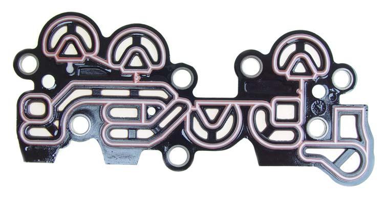
9 Filter and Pan Gasket Filter bolts Filter part # 1L2Z 7A 098 AC 9

10 Valve Body Bolts E H E B B A E E E B B B E E E B B F F F F F F G F G F F F H C D G G F 10

11 Solenoid body bolts torque to 71 in. lb. A piece Torx B pieces Torx Valve body & filter bolts torque to 89 in.lb C piece 8mm D piece 8mm E pieces 8mm F pieces 8mm G piece 10mm H filter bolts 2 pieces 8mm G reverse servo body bolts 4 pieces 8mm 11

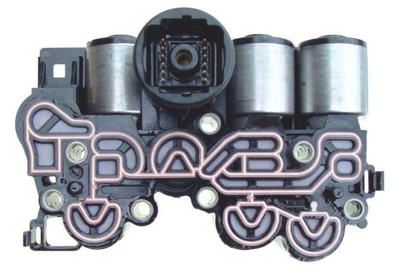
12 Valve Body 12

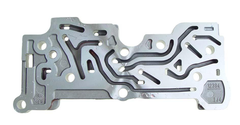
13 A.946 plate bolts 3 pieces Torque to 89 in. lb. A locations A A 13

14 Valve Body 14
15 .984 x.277 x.023 VFS1 modulator #1 booster #2 booster Main regulator x.380 x x.722 x x 380 x x.360 x.036 Solenoid regulator Converter limit Manual 15
16 Converter clutch modulator.879 x.206 x.015 Converter clutch modulator control OD servo control.721 x.212 x.027 Forward engagement control x.326 x.029 RS ISA select.830 x.245 x.026 Rear servo control.836 x.282 x

17 B B Install.250 rubber balls at the B locations 17
18 Converter clutch control.910 x.241 x.023 Fluid cooler bypass x.625 x.035 Thermo assembly x.322 x x.321 x.030 Converter clutch back pressure Coast clutch control.971 x.277 x.025 VFS2 modulator Intermediate servo release x.321 x.030 High clutch control Reverse modulator x.321 x x.323 x.025 Reverse engagement.917 x.322 x

19 Separator Plate Gaskets are bonded to the separator plate 19
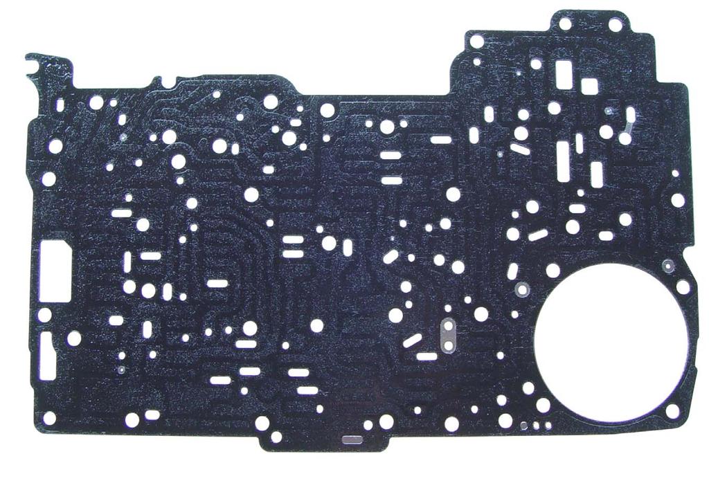
20 20

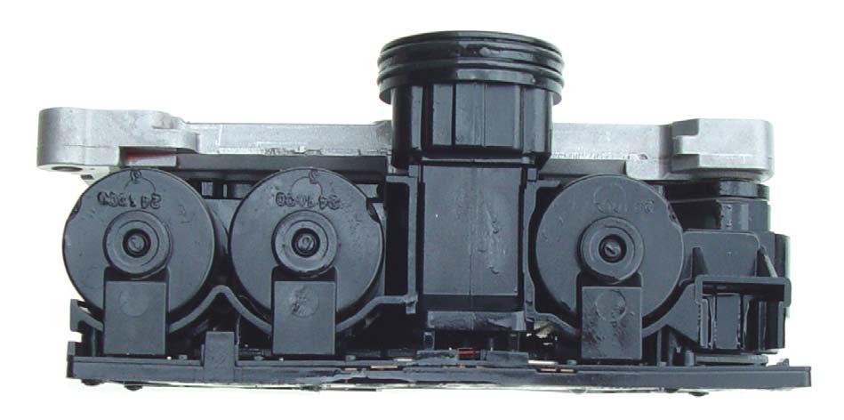
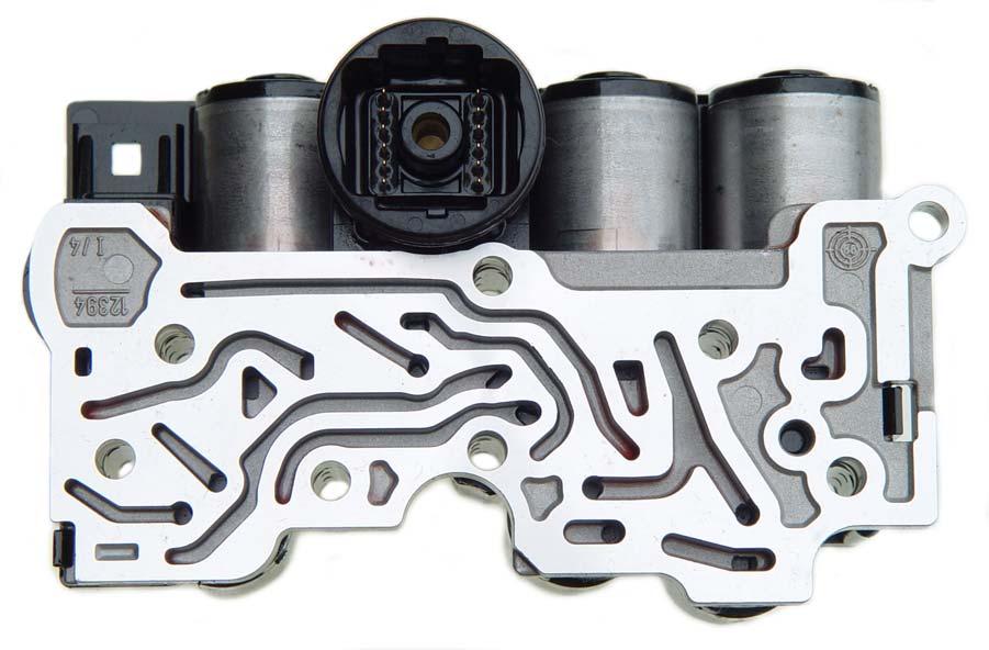
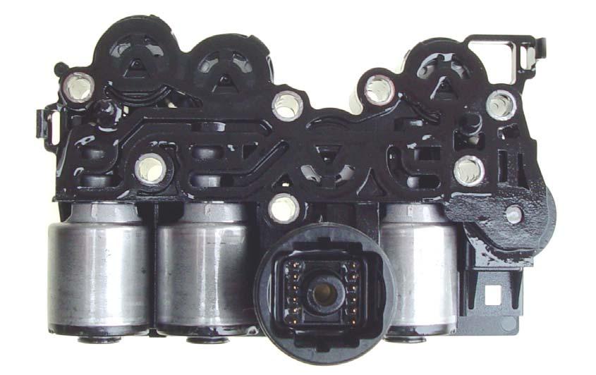
21 Solenoid Body 21
22 22
23 23


24 Low / Reverse Servo & Band Make sure arrow on cover is aligned on servo body as shown. To remove cover align arrow on cover with one of the three slots. 24

25 Torque to 90 in. lb x.331 x Reverse servo check valve Rubber o-ring x x.134


26 Check band anchor pins for looseness in the case. Low & reverse band 26

27 Valve Body Alignment Pins and Center Support Bolt Alignment pin Torque center support bolt to 8 lb. ft. Alignment pin Use Ford alignment pins # at locations shown. 27


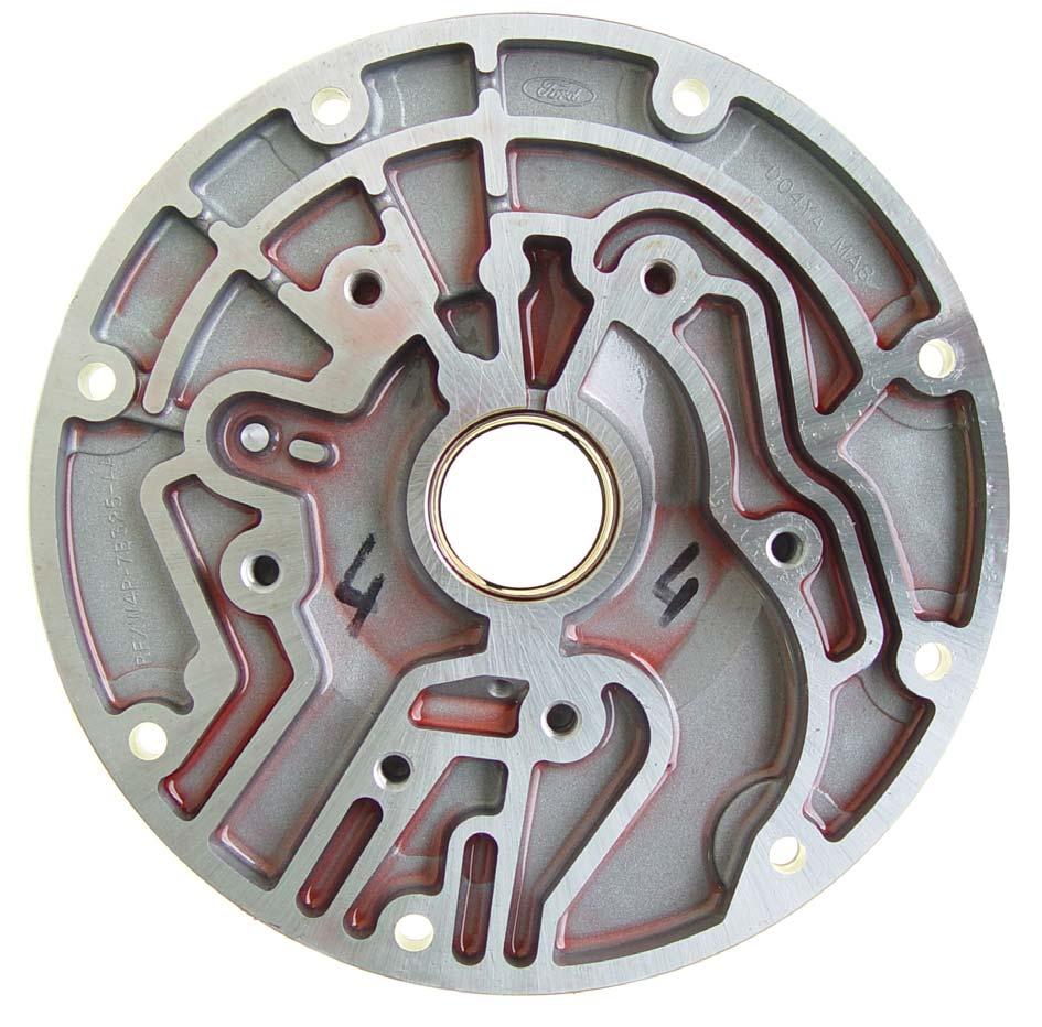
28 Pump Assembly Torque pump bolts to 18 lb. ft. A pump puller is necessary to remove the pump. 28

29 Pump Alignment & Tool 1. Assemble & Align Pump Start bolts, leave pump halves loose. Slide Pump Tool over stator spline. Push tool, while wiggling pump body making sure tool enters and snugs in the pump bushing. Tighten the pump bolts to 18 ft lbs. Pump tool 29

30 Plastic selective thrust washer available in the following sizes.060 brown.070 red.080 black.090 orange.100 purple Torque bolts to 18 ft. lb. 30
31 31

32 Pump wear plate should be scratch free. 32

33 33 Pump valve


34 Rubber o-ring Dimples on pump gears face down. Pump valve and o-ring 34


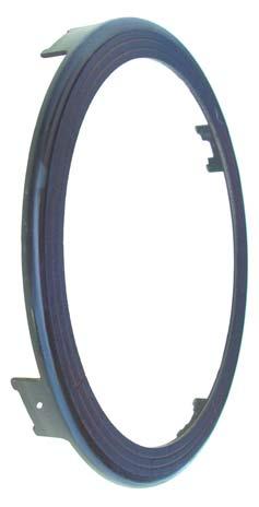
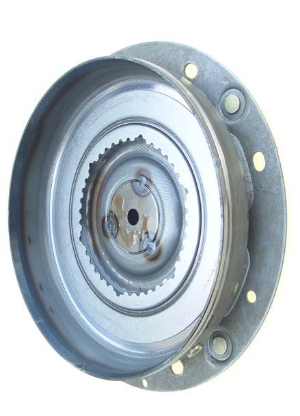
35 Internal Components Pump assembly Turbine shaft Overdrive band Coast clutch drum Plastic selective washer Overdrive sun gear spacer adapter Overdrive ring gear Overdrive sun gear Roller bearing Overdrive carrier 35


36 Tapered side faces up Center support Roller bearing inner lip faces up Intermediate band Intermediate brake drum Selective roller bearing No notch.110 One notch.116 Two notch.124 Three notch.132 Inner lip faces down Forward drum Roller bearing inner lip faces down Roller bearing inner lip faces up Washer 36


37 Forward planetary ring gear Roller bearing inner lip faces down Forward planetary Sun gear shell Sun gear spacer Roller bearing inner lip faces up Low and reverse planetary carrier Plastic spacer Snap ring Snap ring Roller bearing inner lip faces up 37


38 Roller bearing inner race faces up. Teflon sealing ring Output shaft ring gear Low and reverse brake drum. Low and reverse band 38
39 39
40 40


41 Thrust washer Park gear Output shaft Parking pawl assembly 41

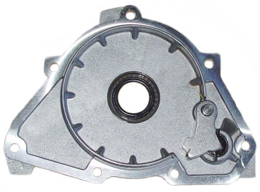
42 Extension housing 42

43 Center Support Snap Ring Snap ring openings are positioned as shown. Tapered side of the snap ring faces up. Snap ring is.141 thick. 43


44 Internal parts differences in the 5R55N,W&S series Turbine shafts are in the 5R55W/S models. The 5R55N use a length shaft from and later 5R55N uses the shaft The coast clutch drum The 5R55N is used in the Lincoln LS and in the Jaguar. The 5R55W/S models are used in the Explorer and Mountaineer. Tabs on the sun gear spacer are straight on the R55N and has straight slots on the drum up 5R55N uses angled slots on the drum and the spacer like the 5R55W/S models. 5R55W/S sun gear spacer is shown actual size. 5R55N has a small inside diameter and only has 24 teeth. 5R55W/S sun gear has 38 teeth. 5R55N has 24 teeth. 44

45 5R55W/S overdrive carrier has 28 tooth pinion gears. 5R55N has 25 tooth pinion gears. 5R55W/S ring gear has 94 teeth. 5R55N has 72 teeth. The retaining snap ring is also different. 5R55W/S measures.050 thickness.194 on wall thickness 5R55N measures.060 thickness.155 on wall thickness 45

46 Forward clutch drum & piston 46 5R55W/S uses a stamped steel piston and spring retainer. The 5R55N uses an aluminum piston and has a spacer ring and later is the same as 5R55W/S

47 5R55W/S forward ring gear uses 101 teeth. The 5R55N has 85 teeth from and then in 2002 and later is the same as 5R55W/S models. 5R55W/S forward planetary is also different having 23 tooth pinion gears. The 5R55N uses 19 tooth gears until 2002 and then is the same as 5R55W/S models. 5R55W/S sun gear has 55 teeth and no roller bearing in bore. The 5R55N has 47 teeth with a roller bearing in the bore until 1999 and then is the same as the 5R55W/S 47 Uses wide spacer. 5R55N uses a sprag assembly.

48 Reverse servo housing, piston and valve are different see dimensions below. Rubber o-ring 48 Piston are different, make sure rubber o-ring fits snug in bore of piston R55W/S R55N

49 Servo Assemblies and Band Adjustment Servo pins wear the case bore causing a slip in 2nd, 3rd and 5th gear. The case usually needs repair by 70,000 miles. Repair kit is available from servobore.com Or call FAX Overdrive servo Works 2nd and 5th gears. Intermediate servo Works 3rd gear. 49


50 1.627 x.727 x.088 Overdrive servo x.727 x.088 Intermediate servo 50


51 Servo strut must face as shown. Overdrive band adjustment Tighten band adjusting screw to 120 in. lb. then back off two turns. Then tighten lock nut to 40 ft. lb. Intermediate band adjustment Tighten band adjusting screw to 120 in. lb. then back off two turns. Then tighten lock nut to 40 ft. lb. 51


52 Coast Clutch Clutch piston return springs measure x.323 x steel.069 friction.063 steel.199 pressure plate.065 selective snap ring Notice direction of grooves on friction plates. Clutch pack clearance should be


53 Direct Clutch Clutch piston return springs measure x.323 x friction Externally splined.083 friction Internally splined.199 pressure plate.065 selective snap ring Frictions are single sided. Be sure to alternate internally splined and externally splined clutches as shown.


54 Clutch pack clearance should be The back side of frictions operate as a steel plate. 54

55 Forward Clutch steel.065 steel Grooves in friction should face as shown..065 steel.065 steel.065 steel.080 selective snap ring Clutch clearance should be friction.068 friction.068 friction.068 friction.068 friction.156 pressure plate
56 Clutch Pack Selective Snap Rings Coast Clutch and Direct Clutch Selective Snap Ring Chart Thickness Part #.054 E S.068 E S.082 E S.096 E S Forward Clutch Selective Snap Ring Chart Thickness Part#.068 XW4Z-7D483-AB.082 XW4Z-7D483-AC.096 XW4Z-7D483-AD 56


57 Overdrive One Way Clutch Rotation Rotate Hold Hold O.D. Planet Carrier assembly and rotate O.D. center shaft. It should freewheel in the direction of the arrow. Overdrive One Way Clutch 57


58 Low/Reverse One Way Clutch Reverse brake drum One way clutch Low/Reverse brake drum should rotate clockwise when installed in the case as shown. 58

59 Digital Transmission Range (DTR) Sensor and Speed Sensors Turbine shaft sensor (TSS) Intermediate shaft sensor (ISS) Output shaft sensor (OSS) Torque DTR mounting bolts to 90 in lbs. Torque manual lever nut to 35 ft.lbs. Digital Transmission Range (DTR) Sensor Pin Number Function Not used 2 Signal Return 3 TR3A 4 TR1 5 TR2 6 TR4 7 Ground 8 Neutral 9 Power Feed 10 Starter Control 11 Back-up 12 Starter to Interrupt relay 59


60 All of the sensors are marked XW4P 7H 103AA at this location. Torque sensor bolts to 90 in. lbs. The one stamped 0900 installs at the turbine shaft sensor location The two stamped 2950 install at the intermediate shaft sensor and the output shaft sensor locations. 60


61 Case Connector Pressure control B TFT Shift solenoid power Pressure control C Shift solenoid D Shift solenoid C Pressure control A Signal return Not used TCC Shift solenoid B Shift solenoid A TFT transmission fluid temperature sensor. 61
62 Gear Ratios & Clutch, Band Application Chart 5R55S Gear Ratios 1st nd rd 1,55 4th th 0.71 Rev R55W Gear Ratios 1st nd rd 1,55 4th th 0.75 Rev Band & Clutch Application Chart Gear 1st 2nd 3rd 4th 5th Reverse Applied Band or Clutch Forward Clutch & low One way Low Sprag *, Forward Clutch & Overdrive Band *, Forward Clutch & Intermediate Band *, Forward Clutch & Direct Clutch Forward Clutch, Direct Clutch & Overdrive Band Reverse Band, Direct Clutch & Coast Clutch * = Direct One Way Overdrive Sprag 62


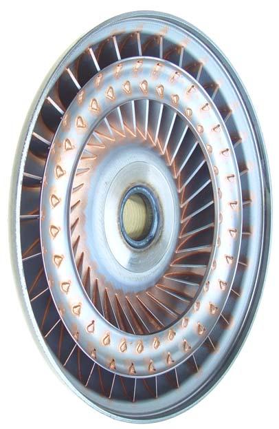
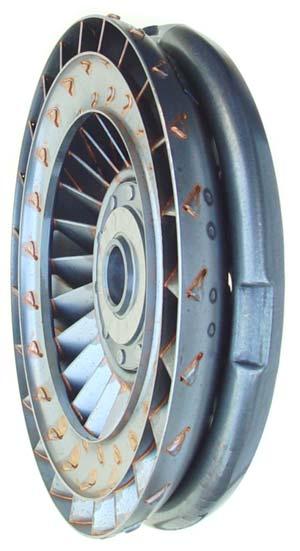
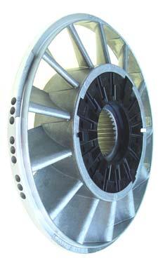
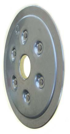
63 Torque Converter Torque the converter drain plug to 89 in. lb. 63
64 64


65 Torque these 8 nuts to 33 lb. ft. Torque these 4 nuts to 28 lb. ft. 65
66 Scan Tools Available from Ford Aftermarket scan tools: SnapOn or local dealer Or Ease Diagnostics or
67 67 A Ampere(s)/Amp(s) ABS Antilock Brake System A/C Air Conditioning AC Alternating Current ACC Automatic Climate Control ACL Air Cleaner ACR4 Air Conditioning Refrigerant, Recovery, Recycling, Recharging A/D Analog to Digital ADL Automatic Door Lock A/F Air/Fuel Ratio AIR Secondary Air Injection ALC Automatic Level Control AM/FM Amplitude Modulation/Frequency Modulation Ant Antenna AP Accelerator Pedal API American Protection Institute APP Accelerator Pedal Position APT Adjustable Part Throttle ARS Automatic Restraint System A/T Automatic Transmission/ Transaxle ATC Automatic Temperature Control ATDC After Top Dead Center Auto Automatic avg Average AWD All Wheel Drive AWG American Wire Gage B+ Battery Positive Voltage B Battery Negative Voltage BARO Barometric Pressure sensor batt Battery BBV Brake Booster Vacuum BCM Body Control Module BHP Brake Horsepower BLK Black BLU Blue BOO Brake on / off switch BP Back Pressure BPM Brake Pressure Modulator BPMV Brake Pressure Modulator Valve BPP Brake Pedal Position BRN Brown BTDC Before Top Dead Center BTSI Brake Transmission Shift Interlock Abbreviations Btu British Thermal Units C Degrees Celsius CAC Charge Air Cooler CAFÉ Corporate Average Fuel Economy Cal Calibration Cam Camshaft CARB Calif Air Resources Board cc cubic centimeters CCM Central Control Module CCOT Cycling Clutch Orifice Tube CCP Climate Control Panel CD Compact Disc CE Commutator End CEAB Cold Engine Air Bleed CEMF Counter Electromotive Force cfm cubic feet per minute cg center of gravity CID Cubic Inch Displacement CKP Crankshaft Position sensor CKT Circuit CL Closed Loop C/Ltr Cigar Lighter CMP Camshaft Position sensor CNG Compressed Natural Gas CO Carbon Monoxide CO2 Carbon Dioxide Coax Coaxial COMM Communication Conn Connector CPA Connector Position Assurance CPP Clutch Pedal Position CPS Central Power Supply CPU Central Processing Unit CRT Cathode Ray Tube CRTC Cathode Ray Tube Controller CS Charging System CTP Closed Throttle Position cu ft Cubic foot/feet cu in Cubic inch/inches CV Constant Velocity (Joint) Cyl Cylinder(s) DAB Delayed Accessory Bus DB Decibels on A-weighted Scale DC Direct Current DCM Door Control Module DE Drive End DEC Digital Electronic Controller DERM Diagnostic Energy Reserve Module DI Distributor Ignition dia diameter DIC Driver Information Center Diff Differential DK Dark DLC Data Link Connector DMM Digital Multimeter DOHC Dual Overhead Camshafts DR Driver DRL Daytime Running Lamps DTC Diagnostic Trouble Code DTM Diagnostic test mode EBCM Electronic Brake Control Module EBTCM Electronic Brake & Traction Control Module EC Electrical Center ECC Electronic Climate Control ECI Extended Compressor at Idle ECL Engine Coolant Level ECM Engine Control Module ECS Emission Control System ECT Engine Coolant Temperature EEPROM Electronically Erasable Programmable Read Only Memory EEVIR Evaporator Equalized Values in Receiver EFE Early Fuel Evaporation EGR Exhaust Gas Recirculation EGRTVV Exhaust Gas Recirculation Thermal Vacuum Valve EI Electronic Ignition ELAP Elapsed ELC Electronic Level Control E/M English/Metric EMF Electromotive Force Eng Engine EOP Engine Oil Pressure EOT Engine Oil Temperature EPA Environmental Protection Agency EPR Exhaust Pressure Regulator EPROM Erasable Programmable Read Only Memory ESC Electronic Suspension Control ESD Electrostatic Discharge ETC Electronic Throttle Control or Electronic Temperature Control
68 68 ETR Electronically Tuned Receiver EVAP Evaporative Emission EVO Electronic Variable Orifice Exh Exhaust F Degrees Farenheit FC Fan Control FDC Fuel Data Center FED Federal (all United States except Calif) FEDS Fuel Enable Data Stream FF Flexible Fuel FI Fuel Injection FMEM Failure management effects mode FMVSS Federal Motor Vehicle Safety Standards F/P Fuel Pump Ft foot/feet FT Fuel Trim F4WD Full Time Four Wheel Drive 4WAL Four Wheel Antilock 4WD Four Wheel Drive FW Flat Wire FWD Front Wheel Drive g gram(s) or Gravitational Acceleration GA Gage gal gallon(s) gas gasoline GCW Gross Combination Weight Gen Generator GL Gear Lubricant GM General Motors GM SPO General Motors Service Parts Operations gnd ground gpm gallons per minute GRN Green GRY Gray GVWR Gross Vehicle Weight Rating H Hydrogen H2O Water Harn Harness HC Hydrocarbons H/CMPR High Compression HD Heavy Duty HDC Heavy Duty Cooling hex hexagon Hg Mercury Hi Alt High Altitude HO2S Heated Oxygen Sensor hp horsepower HPL High Pressure Liquid HPS High Performance System HPV High Pressure Vapor Htd Heated HTR Heater HUD Head-up Display HVAC Heater-Vent-Air Conditioning HVACM Heater-Vent-Air Conditioning Module HVM Heater Vent Module Hz Hertz IAC Idle Air Control IAT Intake Air Temperature IC Integrated Circuit or Ignition Control ICM Ignition Control Module ID Identification or Inside Diameter IDI Integrated Direct Ignition ign ignition ILC Idle Load Compensator in inch(es) INJ Injection inst instantaneous I/P Instrument Panel IPC Instrument Panel Cluster I/PEC Instrument Panel Electrical Center ISC Idle Speed Control ISO International Standards Organization ISS Input Speed Shaft KAM Keep Alive Memory KDD Keyboard Display Driver kg kilogram khz kilohertz km kilometer km/h kilometers per hour km/l kilometers per liter kpa kilopascals KS Knock Sensor kv kilovolts L Liter L4 In-Line Four Cylinder Engine L6 In-Line Six Cylinder Engine lb pound lb ft pound feet (torque) lb in pound inch (torque) LCD Liquid Crystal Display LDCL Left Door Closed Locking LDCM Left Door Control Module LED Light Emitting Diode LF Left Front LH Left Hand Lm lumens LR Left Rear lt left LT Light MAF Mass Air Flow Man Manual MAP Manifold Absolute Pressure MAT Manifold Absolute Temperature max maximum M/C Mixture Control MDP Manifold Differential Pressure MFI Multiport Fuel Injection mi mile(s) MIL Malfunction Indicator Lamp min minimum ml milliliter MLP Manual lever position sensor mm millimeter mpg miles per gallon mph miles per hour ms millisecond MST Manifold Surface Temperature M/T Manual Transmission/Transaxle MV Megavolt mv millivolt NAES North American Export Sales NC Normally Closed NEG Negative Neu Neutral NLGI National Lubricating Grease Institute N-m Newton-meter (torque) NO Normally Open NOx Nitrogen Oxides NPTC National Pipe Thread-Course NPTF National Pipe Thread-Fine NVRAM Non-volatile Random Access Memory O2 Oxygen O2S Oxygen Sensor OBD II On-board Diagnostics II OC Oxidation Converter (Catalytic) OD Outside Diameter ODO Odometer OE Original Equipment OEM Original Equipment Manufacturer OHC Overhead Camshaft OL Open Loop ORN Orange OSS Output Shaft Speed oz ounce(s) PAG Polyalkylene Glycol PASS Passenger
69 69 P/B Power Brakes PC Pressure Control PCB Printed Circuit Board PCM Powertrain Control Module PCS Pressure Control Solenoid PCV Positive Crankcase Ventilation PM Permanent Magnet (Generator) P/N Part Number PNK Pink PNP Park/Neutral Position PRNDL Park, Reverse, Neutral, Drive, Low POA Pilot Operated Absolute (Valve) POS Positive POT Potentiometer (Variable Resistor) PPL Purple ppm parts per million PROM Programmable Read Only Memory P/S Power Steering PSD Power Sliding Door PSP Power Steering Pressure psi pounds per square inch psia pounds per square inch absolute psig pounds per square inch guage pt pint PWM Pulse Width Modulated qt quart(s) R-12 Refrigerant-12 R-134a Refrigerant-134a RAM Random Access Memory (impermanent memory device; memory contents lost when power removed) RAP Retained Accessory Power RAV Remote Activation Verification RCDLR Remote Control Door Lock Receiver RDCM Right Door Control Module Ref Reference Rev Reverse RF Right Front or Radio Frequency RFA Remote Function Actuation RFI Radio Frequency Interference RH Right Hand Rly relay RM Relay module ROM Read Only Memory (permanent memory device) RPM Revolutions Per Minute Engine Speed RPO Regular Production Option RR Right Rear rt right RTD Real Time Damping RTV Room Temperature Vulcanizing (Sealer) RWAL Rear Wheel Antilock RWD Rear Wheel Drive s second(s) SAE Society of Automotive Engineers SC Supercharger SCB Supercharger Bypass SCM Seat Control Module SDM Sensing & Diagnostic Module SEO Special Equipment Option SFI Sequential Multiport Fuel Injection SI System International (modern version of metric system) SIR Supplemental Inflatable Restraint SLA Short/Long Arm sol solenoid SO2 Sulfur Dioxide SP Splice Pack SPO Service Parts Operations sq ft square foot/feet sq in square inch(es) SRC Service Ride Control SRI Service Reminder Indicator ST Scan Tool S4WD Selectable Four Wheel Drive sw Switch syn synchronizer Tach Tachometer TB Throttle body TBI Throttle Body Fuel Injection TC Turbocharger TCC Torque Converter Clutch TCIL Transmission control indicator lamp TCS Transmission control switch TDC Top Dead Center TEMP Temperature Term Terminal TFP Transmission Fluid Pressure TFT Transmission Fluid Temperature TOC Transmission Oil Cooler TP Throttle Position TPA Terminal Positive Assurance TPM Tire Pressure Monitoring TR Transmission Range / Sensor TRANS Transmission/Transaxle TSS Turbine shaft sensor TVRS Television & Radio Suppression TVV Thermal Vacuum Valve TWC Three-way Converter (Catalytic) TWC+OC Three-way + Oxidation Converter (Catalytic) TXV Thermal Expansion Valve UART Universal Asynchronous Receive & Transmit U/H Under Hood U/HEC Under Hood Electrical Center U-Joint Universal Joint UTD Universal Theft Deterrent UV Ultraviolet V Volt(s) or Voltage V6 V-type 6 Cylinder Engine V8 V-type 8 Cylinder Engine Vac Vacuum VAC Vehicle Access Code VATS Vehicle Anti-theft System VCM Vehicle Control Module VDOT Variable Displacement Orifice Tube VDV Vacuum Delay Valve vel velocity VES Variable Effort Steering VF Vacuum Fluorescent VIO Violet VIN Vehicle Identification Number VMV Vacuum Modulator Valve VR Voltage Regulator V ref Voltage reference VSS Vehicle Speed Sensor also called OSS sensor W/ with W/B Wheel Base WHL Wheel WHT White W/o without WOT Wide Open Throttle W/P Water Pump W/S Windshield WSS Wheel Speed Sensor WU-OC Warm-up Oxidation Converter (Catalytic) WU-TWC Warm-up Three-way Converter (Catalytic) X-valve Expansion Valve yd yard(s) YEL Yellow
70 SAE OBDII Code Listing P0100 Mass or Volume Air Flow Circuit Malfunction P0101 Mass or Volume Air Flow Circuit Range/Performance Problem P0102 Mass or Volume Air Flow Circuit Low Input P0103 Mass or Volume Air Flow Circuit High Input P0104 Mass or Volume Air Flow Circuit Intermittent P0105 Manifold Absolute Pressure/Barometric Pressure Circuit Malfunction P0106 Manifold Absolute Pressure/Barometric Pressure Circuit Range/Performance P0107 Manifold Absolute Pressure/Barometric Pressure Circuit Low Input P0108 Manifold Absolute Pressure/Barometric Pressure Circuit High Input P0109 Manifold Absolute Pressure/Barometric Pressure Circuit Intermittent P0109 Intake Air Temperature Circuit Malfunction P0111 Intake Air Temperature Circuit Range/Performance Problem P0112 Intake Air Temperature Circuit Low Input P0113 Intake Air Temperature Circuit High Input P0114 Intake Air Temperature Circuit Intermittent P0115 Engine Coolant Temperature Circuit Malfunction P0116 Engine Coolant Temperature Circuit Range/Performance Problem P0117 Engine Coolant Temperature Circuit Low Input P0118 Engine Coolant Temperature Circuit High Input P0119 Engine Coolant Temperature Circuit Intermittent P0120 Throttle/Petal Position Sensor/Switch A Circuit Malfunction P0121 Throttle/Petal Position Sensor/Switch A Circuit Range/Performance Problem P0122 Throttle/Petal Position Sensor/Switch A Circuit Low Input P0123 Throttle/Petal Position Sensor/Switch A Circuit High Input P0124 Throttle/Petal Position Sensor/Switch A Circuit Intermittent P0125 Insufficient Coolant Temperature for Closed Loop Fuel Control P0126 Insufficient Coolant Temperature for Stable Operation P Sensor Circuit Malfunction (Bank 1 Sensor 1) P Sensor Circuit Low Voltage (Bank 1 Sensor 1) P Sensor Circuit High Voltage (Bank 1 Sensor 1) P Sensor Circuit Slow Response (Bank 1 Sensor 1) P Sensor Circuit No Activity Detected (Bank 1 Sensor 1) P Sensor Heater Circuit Malfunction (Bank 1 Sensor 1) P Sensor Circuit Malfunction (Bank 1 Sensor 2) P Sensor Circuit Low Voltage (Bank 1 Sensor 2) P Sensor Circuit High Voltage (Bank 1 Sensor 2) P Sensor Circuit Slow Response (Bank 1 Sensor 2) P Sensor Circuit No Activity Detected (Bank 1 Sensor 2) P Sensor Heater Circuit Malfunction (Bank 1 Sensor 2) P Sensor Circuit Malfunction (Bank 1 Sensor 3) P Sensor Circuit Low Voltage (Bank 1 Sensor 3) P Sensor Circuit High Voltage (Bank 1 Sensor 3) P Sensor Circuit Slow Response (Bank 1 Sensor 3) P Sensor Circuit No Activity Detected (Bank 1 Sensor 3) P Sensor Heater Circuit Malfunction (Bank 1 Sensor 3) P Sensor Circuit Malfunction (Bank 2 Sensor 1) P Sensor Circuit Low Voltage (Bank 2 Sensor 1) P Sensor Circuit High Voltage (Bank 2 Sensor 1) P Sensor Circuit Slow Response (Bank 2 Sensor 1) P Sensor Circuit No Activity Detected (Bank 2 Sensor 1) P Sensor Heater Circuit Malfunction (Bank 2 Sensor 1) 70
71 P Sensor Circuit Malfunction (Bank 2 Sensor 2) P Sensor Circuit Low Voltage (Bank 2 Sensor 2) P Sensor Circuit High Voltage (Bank 2 Sensor 2) P Sensor Circuit Slow Response (Bank 2 Sensor 2) P Sensor Circuit No Activity Detected (Bank 2 Sensor 2) P Sensor Heater Circuit Malfunction (Bank 2 Sensor 2) P Sensor Circuit Malfunction (Bank 2 Sensor 3) P Sensor Circuit Low Voltage (Bank 2 Sensor 3) P Sensor Circuit High Voltage (Bank 2 Sensor 3) P Sensor Circuit Slow Response (Bank 2 Sensor 3) P Sensor Circuit No Activity Detected (Bank 2 Sensor 3) P Sensor Heater Circuit Malfunction (Bank 2 Sensor 3) P0170 Fuel Trim Malfunction (Bank 1) P0171 System too Lean (Bank 1) P0172 System too Rich (Bank 1) P0173 Fuel Trim Malfunction (Bank 2) P0174 System too Lean (Bank 2) P0175 System too Rich (Bank 2) P0176 Fuel Composition Sensor Circuit Malfunction P0177 Fuel Composition Sensor Circuit Range/Performance P0178 Fuel Composition Sensor Circuit Low Input P0179 Fuel Composition Sensor Circuit High Input P0180 Fuel Temperature Sensor A Circuit Malfunction P0181 Fuel Temperature Sensor A Circuit Range/Performance P0182 Fuel Temperature Sensor A Circuit Low Input P0183 Fuel Temperature Sensor A Circuit High Input P0184 Fuel Temperature Sensor A Circuit Intermittent P0185 Fuel Temperature Sensor B Circuit Malfunction P0186 Fuel Temperature Sensor B Circuit Range/Performance P0187 Fuel Temperature Sensor B Circuit Low Input P0188 Fuel Temperature Sensor B Circuit High Input P0189 Fuel Temperature Sensor B Circuit Intermittent P0190 Fuel Rail Pressure Sensor Circuit Malfunction P0191 Fuel Rail Pressure Sensor Circuit Range/Performance P0192 Fuel Rail Pressure Sensor Circuit Low Input P0193 Fuel Rail Pressure Sensor Circuit High Input P0194 Fuel Rail Pressure Sensor Circuit Intermittent P0195 Engine Oil Temperature Sensor Malfunction P0196 Engine Oil Temperature Sensor Range/Performance P0197 Engine Oil Temperature Sensor Low P0198 Engine Oil Temperature Sensor High P0199 Engine Oil Temperature Sensor Intermittent P0200 Injector Circuit Malfunction P0201 Injector Circuit Malfunction - Cylinder 1 P0202 Injector Circuit Malfunction - Cylinder 2 P0203 Injector Circuit Malfunction - Cylinder 3 P0204 Injector Circuit Malfunction - Cylinder 4 P0205 Injector Circuit Malfunction - Cylinder 5 P0206 Injector Circuit Malfunction - Cylinder 6 P0207 Injector Circuit Malfunction - Cylinder 7 P0208 Injector Circuit Malfunction - Cylinder 8 P0209 Injector Circuit Malfunction - Cylinder 9 P0210 Injector Circuit Malfunction - Cylinder 10 71
72 P0211 Injector Circuit Malfunction - Cylinder 11 P0212 Injector Circuit Malfunction - Cylinder 12 P0213 Cold Start Injector 1 Malfunction P0214 Cold Start Injector 2 Malfunction P0215 Engine Shutoff Solenoid Malfunction P0216 Injection Timing Control Circuit Malfunction P0217 Engine Overtemp Condition P0218 Transmission Over Temperature Condition P0219 Engine Overspeed Condition P0220 Throttle/Petal Position Sensor/Switch B Circuit Malfunction P0221 Throttle/Petal Position Sensor/Switch B Circuit Range/Performance Problem P0222 Throttle/Petal Position Sensor/Switch B Circuit Low Input P0223 Throttle/Petal Position Sensor/Switch B Circuit High Input P0224 Throttle/Petal Position Sensor/Switch B Circuit Intermittent P0225 Throttle/Petal Position Sensor/Switch C Circuit Malfunction P0226 Throttle/Petal Position Sensor/Switch C Circuit Range/Performance Problem P0227 Throttle/Petal Position Sensor/Switch C Circuit Low Input P0228 Throttle/Petal Position Sensor/Switch C Circuit High Input P0229 Throttle/Petal Position Sensor/Switch C Circuit Intermittent P0230 Fuel Pump Primary Circuit Malfunction P0231 Fuel Pump Secondary Circuit Low P0232 Fuel Pump Secondary Circuit High P0233 Fuel Pump Secondary Circuit Intermittent P0234 Engine Overboost Condition P0235 Turbocharger Boost Sensor A Circuit Malfunction P0236 Turbocharger Boost Sensor A Circuit Range/Performance P0237 Turbocharger Boost Sensor A Circuit Low P0238 Turbocharger Boost Sensor A Circuit High P0239 Turbocharger Boost Sensor B Malfunction P0240 Turbocharger Boost Sensor B Circuit Range/Performance P0241 Turbocharger Boost Sensor B Circuit Low P0242 Turbocharger Boost Sensor B Circuit High P0243 Turbocharger Wastegate Solenoid A Malfunction P0244 Turbocharger Wastegate Solenoid A Range/Performance P0245 Turbocharger Wastegate Solenoid A Low P0246 Turbocharger Wastegate Solenoid A High P0247 Turbocharger Wastegate Solenoid B Malfunction P0248 Turbocharger Wastegate Solenoid B Range/Performance P0249 Turbocharger Wastegate Solenoid B Low P0250 Turbocharger Wastegate Solenoid B High P0251 Injection Pump Fuel Metering Control "A" Malfunction (Cam/Rotor/Injector) P0252 Injection Pump Fuel Metering Control "A" Range/Performance (Cam/Rotor/Injector) P0253 Injection Pump Fuel Metering Control "A" Low (Cam/Rotor/Injector) P0254 Injection Pump Fuel Metering Control "A" High (Cam/Rotor/Injector) P0255 Injection Pump Fuel Metering Control "A" Intermittent (Cam/Rotor/Injector) P0256 Injection Pump Fuel Metering Control "B" Malfunction (Cam/Rotor/Injector) P0257 Injection Pump Fuel Metering Control "B" Range/Performance (Cam/Rotor/Injector) P0258 Injection Pump Fuel Metering Control "B" Low (Cam/Rotor/Injector) P0259 Injection Pump Fuel Metering Control "B" High (Cam/Rotor/Injector) P0260 Injection Pump Fuel Metering Control "B" Intermittent (Cam/Rotor/Injector) P0261 Cylinder 1 Injector Circuit Low P0262 Cylinder 1 Injector Circuit High P0263 Cylinder 1 Contribution/Balance Fault 72
73 P0264 Cylinder 2 Injector Circuit Low P0265 Cylinder 2 Injector Circuit High P0266 Cylinder 2 Contribution/Balance Fault P0267 Cylinder 3 Injector Circuit Low P0268 Cylinder 3 Injector Circuit High P0269 Cylinder 3 Contribution/Balance Fault P0270 Cylinder 4 Injector Circuit Low P0271 Cylinder 4 Injector Circuit High P0272 Cylinder 4 Contribution/Balance Fault P0273 Cylinder 5 Injector Circuit Low P0274 Cylinder 5 Injector Circuit High P0275 Cylinder 5 Contribution/Balance Fault P0276 Cylinder 6 Injector Circuit Low P0277 Cylinder 6 Injector Circuit High P0278 Cylinder 6 Contribution/Balance Fault P0279 Cylinder 7 Injector Circuit Low P0280 Cylinder 7 Injector Circuit High P0281 Cylinder 7 Contribution/Balance Fault P0282 Cylinder 8 Injector Circuit Low P0283 Cylinder 8 Injector Circuit High P0284 Cylinder 8 Contribution/Balance Fault P0285 Cylinder 9 Injector Circuit Low P0286 Cylinder 9 Injector Circuit High P0287 Cylinder 9 Contribution/Balance Fault P0288 Cylinder 10 Injector Circuit Low P0289 Cylinder 10 Injector Circuit High P0290 Cylinder 10 Contribution/Balance Fault P0291 Cylinder 11 Injector Circuit Low P0292 Cylinder 11 Injector Circuit High P0293 Cylinder 11 Contribution/Balance Fault P0294 Cylinder 12 Injector Circuit Low P0295 Cylinder 12 Injector Circuit High P0296 Cylinder 12 Contribution/Range Fault P0300 Random/Multiple Cylinder Misfire Detected P0301 Cylinder 1 Misfire Detected P0302 Cylinder 2 Misfire Detected P0303 Cylinder 3 Misfire Detected P0304 Cylinder 4 Misfire Detected P0305 Cylinder 5 Misfire Detected P0306 Cylinder 6 Misfire Detected P0307 Cylinder 7 Misfire Detected P0308 Cylinder 8 Misfire Detected P0309 Cylinder 9 Misfire Detected P0311 Cylinder 11 Misfire Detected P0312 Cylinder 12 Misfire Detected P0320 Ignition/Distributor Engine Speed Input Circuit Malfunction P0321 Ignition/Distributor Engine Speed Input Circuit Range/Performance P0322 Ignition/Distributor Engine Speed Input Circuit No Signal P0323 Ignition/Distributor Engine Speed Input Circuit Intermittent P0325 Knock Sensor 1 Circuit Malfunction (Bank 1 or Single Sensor) P0326 Knock Sensor 1 Circuit Range/Performance (Bank 1 or Single Sensor) P0327 Knock Sensor 1 Circuit Low Input (Bank 1 or Single Sensor) P0328 Knock Sensor 1 Circuit High Input (Bank 1 or Single Sensor) 73
74 P0329 Knock Sensor 1 Circuit Intermittent (Bank 1 or Single Sensor) P0330 Knock Sensor 2 Circuit Malfunction (Bank 2) P0331 Knock Sensor 2 Circuit Range/Performance (Bank 2) P0332 Knock Sensor 2 Circuit Low Input (Bank 2) P0333 Knock Sensor 2 Circuit High Input (Bank 2) P0334 Knock Sensor 2 Circuit Intermittent (Bank 2) P0335 Crankshaft Position Sensor A Circuit Malfunction P0336 Crankshaft Position Sensor A Circuit Range/Performance P0337 Crankshaft Position Sensor A Circuit Low Input P0338 Crankshaft Position Sensor A Circuit High Input P0339 Crankshaft Position Sensor A Circuit Intermittent P0340 Camshaft Position Sensor Circuit Malfunction P0341 Camshaft Position Sensor Circuit Range/Performance P0342 Camshaft Position Sensor Circuit Low Input P0343 Camshaft Position Sensor Circuit High Input P0344 Camshaft Position Sensor Circuit Intermittent P0350 Ignition Coil Primary/Secondary Circuit Malfunction P0351 Ignition Coil A Primary/Secondary Circuit Malfunction P0352 Ignition Coil B Primary/Secondary Circuit Malfunction P0353 Ignition Coil C Primary/Secondary Circuit Malfunction P0354 Ignition Coil D Primary/Secondary Circuit Malfunction P0355 Ignition Coil E Primary/Secondary Circuit Malfunction P0356 Ignition Coil F Primary/Secondary Circuit Malfunction P0357 Ignition Coil G Primary/Secondary Circuit Malfunction P0358 Ignition Coil H Primary/Secondary Circuit Malfunction P0359 Ignition Coil I Primary/Secondary Circuit Malfunction P0360 Ignition Coil J Primary/Secondary Circuit Malfunction P0361 Ignition Coil K Primary/Secondary Circuit Malfunction P0362 Ignition Coil L Primary/Secondary Circuit Malfunction P0370 Timing Reference High Resolution Signal A Malfunction P0371 Timing Reference High Resolution Signal A Too Many Pulses P0372 Timing Reference High Resolution Signal A Too Few Pulses P0373 Timing Reference High Resolution Signal A Intermittent/Erratic Pulses P0374 Timing Reference High Resolution Signal A No Pulses P0375 Timing Reference High Resolution Signal B Malfunction P0376 Timing Reference High Resolution Signal B Too Many Pulses P0377 Timing Reference High Resolution Signal B Too Few Pulses P0378 Timing Reference High Resolution Signal B Intermittent/Erratic Pulses P0379 Timing Reference High Resolution Signal B No Pulses P0380 Glow Plug/Heater Circuit "A" Malfunction P0381 Glow Plug/Heater Indicator Circuit Malfunction P0382 Exhaust Gas Recirculation Flow Malfunction P0385 Crankshaft Position Sensor B Circuit Malfunction P0386 Crankshaft Position Sensor B Circuit Range/Performance P0387 Crankshaft Position Sensor B Circuit Low Input P0388 Crankshaft Position Sensor B Circuit High Input P0389 Crankshaft Position Sensor B Circuit Intermittent P0400 Exhaust Gas Recirculation Flow Malfunction P0401 Exhaust Gas Recirculation Flow Insufficient Detected P0402 Exhaust Gas Recirculation Flow Excessive Detected P0403 Exhaust Gas Recirculation Circuit Malfunction P0404 Exhaust Gas Recirculation Circuit Range/Performance P0405 Exhaust Gas Recirculation Sensor A Circuit Low 74
75 P0406 Exhaust Gas Recirculation Sensor A Circuit High P0407 Exhaust Gas Recirculation Sensor B Circuit Low P0408 Exhaust Gas Recirculation Sensor B Circuit High P0410 Secondary Air Injection System Malfunction P0411 Secondary Air Injection System Incorrect Flow Detected P0412 Secondary Air Injection System Switching Valve A Circuit Malfunction P0413 Secondary Air Injection System Switching Valve A Circuit Open P0414 Secondary Air Injection System Switching Valve A Circuit Shorted P0415 Secondary Air Injection System Switching Valve B Circuit Malfunction P0416 Secondary Air Injection System Switching Valve B Circuit Open P0417 Secondary Air Injection System Switching Valve B Circuit Shorted P0418 Secondary Air Injection System Relay "A" Circuit Malfunction P0419 Secondary Air Injection System Relay "B" Circuit Malfunction P0420 Catalyst System Efficiency Below Threshold (Bank 1) P0421 Warm Up Catalyst Efficiency Below Threshold (Bank 1) P0422 Main Catalyst Efficiency Below Threshold (Bank 1) P0423 Heated Catalyst Efficiency Below Threshold (Bank 1) P0424 Heated Catalyst Temperature Below Threshold (Bank 1) P0430 Catalyst System Efficiency Below Threshold (Bank 2) P0431 Warm Up Catalyst Efficiency Below Threshold (Bank 2) P0432 Main Catalyst Efficiency Below Threshold (Bank 2) P0433 Heated Catalyst Efficiency Below Threshold (Bank 2) P0434 Heated Catalyst Temperature Below Threshold (Bank 2) P0440 Evaporative Emission Control System Malfunction P0441 Evaporative Emission Control System Incorrect Purge Flow P0442 Evaporative Emission Control System Leak Detected (small leak) P0443 Evaporative Emission Control System Purge Control Valve Circuit Malfunction P0444 Evaporative Emission Control System Purge Control Valve Circuit Open P0445 Evaporative Emission Control System Purge Control Valve Circuit Shorted P0446 Evaporative Emission Control System Vent Control Circuit Malfunction P0447 Evaporative Emission Control System Vent Control Circuit Open P0448 Evaporative Emission Control System Vent Control Circuit Shorted P0449 Evaporative Emission Control System Vent Valve/Solenoid Circuit Malfunction P0450 Evaporative Emission Control System Pressure Sensor Malfunction P0451 Evaporative Emission Control System Pressure Sensor Range/Performance P0452 Evaporative Emission Control System Pressure Sensor Low Input P0453 Evaporative Emission Control System Pressure Sensor High Input P0454 Evaporative Emission Control System Pressure Sensor Intermittent P0455 Evaporative Emission Control System Leak Detected (gross leak) P0460 Fuel Level Sensor Circuit Malfunction P0461 Fuel Level Sensor Circuit Range/Performance P0462 Fuel Level Sensor Circuit Low Input P0463 Fuel Level Sensor Circuit High Input P0464 Fuel Level Sensor Circuit Intermittent P0465 Purge Flow Sensor Circuit Malfunction P0466 Purge Flow Sensor Circuit Range/Performance P0467 Purge Flow Sensor Circuit Low Input P0468 Purge Flow Sensor Circuit High Input P0469 Purge Flow Sensor Circuit Intermittent P0470 Exhaust Pressure Sensor Malfunction P0471 Exhaust Pressure Sensor Range/Performance P0472 Exhaust Pressure Sensor Low P0473 Exhaust Pressure Sensor High 75
76 P0474 Exhaust Pressure Sensor Intermittent P0475 Exhaust Pressure Control Valve Malfunction P0476 Exhaust Pressure Control Valve Range/Performance P0477 Exhaust Pressure Control Valve Low P0478 Exhaust Pressure Control Valve High P0479 Exhaust Pressure Control Valve Intermittent P0480 Cooling Fan 1 Control Circuit Malfunction P0481 Cooling Fan 2 Control Circuit Malfunction P0482 Cooling Fan 3 Control Circuit Malfunction P0483 Cooling Fan Rationality Check Malfunction P0484 Cooling Fan Circuit Over Current P0485 Cooling Fan Power/Ground Circuit Malfunction P0500 Vehicle Speed Sensor Malfunction P0501 Vehicle Speed Sensor Range/Performance P0502 Vehicle Speed Sensor Low Input P0503 Vehicle Speed Sensor Intermittent/Erratic/High P0505 Idle Control System Malfunction P0506 Idle Control System RPM Lower Than Expected P0507 Idle Control System RPM Higher Than Expected P0510 Closed Throttle Position Switch Malfunction P0520 Engine Oil Pressure Sensor/Switch Circuit Malfunction P0521 Engine Oil Pressure Sensor/Switch Circuit Range/Performance P0522 Engine Oil Pressure Sensor/Switch Circuit Low Voltage P0523 Engine Oil Pressure Sensor/Switch Circuit High Voltage P0530 A/C Refrigerant Pressure Sensor Circuit Malfunction P0531 A/C Refrigerant Pressure Sensor Circuit Range/Performance P0532 A/C Refrigerant Pressure Sensor Circuit Low Input P0533 A/C Refrigerant Pressure Sensor Circuit High Input P0534 Air Conditioner Refrigerant Charge Loss P0550 Power Steering Pressure Sensor Circuit Malfunction P0551 Power Steering Pressure Sensor Circuit Range/Performance P0552 Power Steering Pressure Sensor Circuit Low Input P0553 Power Steering Pressure Sensor Circuit High Input P0554 Power Steering Pressure Sensor Circuit Intermittent P0560 System Voltage Malfunction P0561 System Voltage Unstable P0562 System Voltage Low P0563 System Voltage High P0565 Cruise Control On Signal Malfunction P0566 Cruise Control Off Signal Malfunction P0567 Cruise Control Resume Signal Malfunction P0568 Cruise Control Set Signal Malfunction P0569 Cruise Control Coast Signal Malfunction P0570 Cruise Control Accel Signal Malfunction P0571 Cruise Control/Brake Switch A Circuit Malfunction P0572 Cruise Control/Brake Switch A Circuit Low P0573 Cruise Control/Brake Switch A Circuit High P0574 Cruise Control Related Malfunction P0575 Cruise Control Related Malfunction P0576 Cruise Control Related Malfunction P0576 Cruise Control Related Malfunction P0578 Cruise Control Related Malfunction P0579 Cruise Control Related Malfunction 76
77 P0580 Cruise Control Related Malfunction P0600 Serial Communication Link Malfunction P0601 Internal Control Module Memory Check Sum Error P0602 Control Module Programming Error P0603 Internal Control Module Keep Alive Memory (KAM) Error P0604 Internal Control Module Random Access Memory (RAM) Error P0605 Internal Control Module Read Only Memory (ROM) Error P0606 PCM Processor Fault P0608 Control Module VSS Output "A' Malfunction P0609 Control Module VSS Output "B" Malfunction P0620 Generator Control Circuit Malfunction P0621 Generator Lamp "L" Control Circuit Malfunction P0622 Generator Field "F" Control Circuit Malfunction P0650 Malfunction Indicator Lamp (MIL) Control Circuit Malfunction P0654 Engine RPM Output Circuit Malfunction P0655 Engine Hot Lamp Output Control Circuit Malfunction P0656 Fuel Level Output Circuit Malfunction P0700 Transmission Control System Malfunction P0701 Transmission Control System Range/Performance P0702 Transmission Control System Electrical P0703 Torque Converter/Brake Switch B Circuit Malfunction P0704 Clutch Switch Input Circuit Malfunction P0705 Transmission Range Sensor Circuit malfunction (PRNDL Input) P0706 Transmission Range Sensor Circuit Range/Performance P0707 Transmission Range Sensor Circuit Low Input P0708 Transmission Range Sensor Circuit High Input P0709 Transmission Range Sensor Circuit Intermittent P0710 Transmission Fluid Temperature Sensor Circuit Malfunction P0711 Transmission Fluid Temperature Sensor Circuit Range/Performance P0712 Transmission Fluid Temperature Sensor Circuit Low Input P0713 Transmission Fluid Temperature Sensor Circuit High Input P0714 Transmission Fluid Temperature Sensor Circuit Intermittent P0715 Input/Turbine Speed Sensor Circuit Malfunction P0716 Input/Turbine Speed Sensor Circuit Range/Performance P0717 Input/Turbine Speed Sensor Circuit No Signal P0718 Input/Turbine Speed Sensor Circuit Intermittent P0719 Torque Converter/Brake Switch B Circuit Low P0720 Output Speed Sensor Circuit Malfunction P0721 Output Speed Sensor Range/Performance P0722 Output Speed Sensor No Signal P0723 Output Speed Sensor Intermittent P0724 Torque Converter/Brake Switch B Circuit High P0725 Engine Speed input Circuit Malfunction P0726 Engine Speed Input Circuit Range/Performance P0727 Engine Speed Input Circuit No Signal P0728 Engine Speed Input Circuit Intermittent P0730 Incorrect Gear Ratio P0731 Gear 1 Incorrect ratio P0732 Gear 2 Incorrect ratio P0733 Gear 3 Incorrect ratio P0734 Gear 4 Incorrect ratio P0735 Gear 5 Incorrect ratio P0736 Reverse incorrect gear ratio 77
78 P0740 Torque Converter Clutch Circuit Malfunction P0741 Torque Converter Clutch Circuit Performance or Stuck Off P0742 Torque Converter Clutch Circuit Stuck On P0743 Torque Converter Clutch Circuit Electrical P0744 Torque Converter Clutch Circuit Intermittent P0745 Pressure Control Solenoid Malfunction P0746 Pressure Control Solenoid Performance or Stuck Off P0747 Pressure Control Solenoid Stuck On P0748 Pressure Control Solenoid Electrical P0749 Pressure Control Solenoid Intermittent P0750 Shift Solenoid A Malfunction P0751 Shift Solenoid A Performance or Stuck Off P0752 Shift Solenoid A Stuck On P0753 Shift Solenoid A Electrical P0754 Shift Solenoid A Intermittent P0755 Shift Solenoid B Malfunction P0756 Shift Solenoid B Performance or Stuck Off P0757 Shift Solenoid B Stuck On P0758 Shift Solenoid B Electrical P0759 Shift Solenoid B Intermittent P0760 Shift Solenoid C Malfunction P0761 Shift Solenoid C Performance or Stuck Off P0762 Shift Solenoid C Stuck On P0763 Shift Solenoid C Electrical P0764 Shift Solenoid C Intermittent P0765 Shift Solenoid D Malfunction P0766 Shift Solenoid D Performance or Stuck Off P0767 Shift Solenoid D Stuck On P0768 Shift Solenoid D Electrical P0769 Shift Solenoid D Intermittent P0770 Shift Solenoid E Malfunction P0771 Shift Solenoid E Performance or Stuck Off P0772 Shift Solenoid E Stuck On P0773 Shift Solenoid E Electrical P0774 Shift Solenoid E Intermittent P0780 Shift Malfunction P Shift Malfunction P Shift Malfunction P Shift Malfunction P Shift Malfunction P0785 Shift/Timing Solenoid Malfunction P0786 Shift/Timing Solenoid Range/Performance P0787 Shift/Timing Solenoid Low P0788 Shift/Timing Solenoid High P0789 Shift/Timing Solenoid Intermittent P0790 Normal/Performance Switch Circuit Malfunction P0801 Reverse Inhibit Control Circuit Malfunction P Upshift (Skip Shift) Solenoid Control Circuit Malfunction P Upshift (Skip Shift) Lamp Control Circuit Malfunction 78
79 79 Ford OBDII Code Listing B1231 Longitudinal acceleration threshold exceeded B1318 Battery voltage low B1342 ECU internal failure B1342B ECU is defective B1485 Stop lamp switch input circuit battery short B1676 Battery voltage out of range B1869 Lamp air bag warning indicator circuit open B1870 Lamp air bag warning indicator circuit short to battery B1871 Passenger air bag disable module fault B1877 Seatbelt driver pretensioner circuit open B1878 Seatbelt driver pretensioner circuit short to battery B1879 Seatbelt driver pretensioner circuit short to ground B1881 Seatbelt passenger pretensioner circuit open B1882 Seatbelt passenger pretensioner circuit short to battery B1883 Seatbelt passenger pretensioner circuit short to ground B1884 PAD warning lamp inoperative B1885 Seatbelt driver pretensioner circuit resistance low on squib B1886 Seatbelt passenger pretensioner circuit resistance low on squib B1887 Air bag driver circuit short to ground B1888 Air bag passenger circuit short to ground B1889 Passenger air bag disable module module sensor obstructed B1890 PAD warning lamp circuit short to battery B1891 Air bag tone warning indicator circuit short to battery B1892 Air bag tone warning indicator circuit failure B1900 Driver side air bag fault B1901 Air bag crash sensor #1 feed/return circuit short to ground B1916 Air bag driver circuit short to battery B1921 Air bag diagnostic monitor ground circuit open B1925 Air bag passenger circuit short to battery B1927 Passenger side air bag fault B1932 Air bag driver circuit open B1933 Air bag passenger circuit open B1934 Air bag driver inflator circuit resistance low on squib B1935 Air bag passenger inflator circuit resistance low on squib B1941 Air bag crash sensor #1 feed/return circuit open B2141 NVM configuration failure C1095 Hydraulic pump motor circuit failure C1102 Acceleration switch circuit failure C1145 Wheel speed RF input circuit failure C1155 Wheel speed LF input circuit failure C1165 Wheel speed RR input circuit failure C1175 Wheel speed LR input circuit failure C1230 Rear wheel speed sensor input circuit fault C1233 LF wheel speed signal comparison fault C1234 RF wheel speed signal comparison fault C1235 Speed wheel RR input signal missing C1236 Speed wheel RR input signal missing C1237 Rear wheel speed signal comparison fault C1414 Incorrect module design level P1000 OBDII drive cycle not complete P1001 KOER not able to complete, KOER aborted P1039 Vehicle speed signal missing or improper P1051 Brake switch signal missing or improper P1100 Mass air flow sensor intermittent P1101 Mass air flow (MAF) sensor out of self test range P1112 Intake air temperature sensor intermittent P1116 Engine coolant temperature (ECT) sensor out of self test range P1117 Engine coolant temperature (ECT) sensor intermittent P1118 Manifold air temperature sensor (MAT) (ACT) P1119 Manifold air temperature sensor (MAT) (ACT) P1120 Throttle position circuit out of range low P1121 Throttle position sensor inconsistent with MAF sensor P1124 Throttle position sensor out of self test range P1125 Throttle position sensor intermittent P1127 Exhaust not warm enough downstream oxygen sensor not tested P1128 Upstream oxygen sensors swapped from bank to bank P1129 Downstream oxygen sensors swapped from bank to bank P1130 Lack of HO2S11 switch adaptive fuel at limit (bank 1 upstream) P1131 Lack of HO2S11 switch sensor indicates lean (Bank 1 upstream) P1132 Lack of HO2S11 switch sensor indicates rich (Bank 1 upstream) P1133 HO2S11 fuel control shifted lean (Bank 1upstream) P1134 HO2S11 fuel control shifted rich (Bank 1upstream) P1135 Ignition switch signal missing or improper P1137 Lack of HO2S12 switch sensor indicates lean (Bank 1 downstream) P1138 Lack of HO2S12 switch sensor indicates rich (Bank 1 downstream) P1139 Water in fuel circuit malfunction P1140 Water in fuel condition fail
80 P1141 Fuel restriction indicator circuit malfunction P1142 Fuel restriction switch condition fault P1150 Lack of HO2S12 switch adaptive fuel at limit (Bank 2 upstream) P1151 Lack of HO2S21 switch sensor indicates lean (Bank 2 upstream) P1152 Lack of HO2S21 switch sensor indicates rich (Bank 2 upstream) P1153 HO2S21 fuel control shifted lean (Bank 2 upstream) P1154 HO2S21 fuel control shifted rich (Bank 2 upstream) P1157 Lack of HO2S21 switch sensor indicates lean (Bank 2 downstream) P1158 Lack of HO2S21 switch sensor indicates rich (Bank 2 downstream) P1184 KOER fail engine oil temperature out of self test range P1190 Throttle position sensor B control circuit malfunction P1191 Throttle position sensor B out of range P1192 Throttle position sensor circuit low input P1193 Throttle position sensor circuit high input P1194 Throttle position sensor B out of self test range P1195 Throttle position sensor B inconsistent P1209 Injection control pressure peak delta test fail P1210 Injection control pressure fail maximum pressure test at no-start P1211 KOER fail injection control pressure steady state P1212 Injection control pressure fail minimum pressure test at crank P1220 Throttle position sensor B out of range P1224 Throttle position sensor B out of self test range P1227 Waste gate failed closed (Over pressure) P1228 Waste gate failed open (Under pressure) P1229 Intercooler pump driver fault P1230 Fuel pump low speed malfunction (VLCM) P1231 Fuel pump secondary circuit low high speed (VLCM) P1232 Fuel pump secondary circuit high high speed (VLCM) P1233 Fuel system disabled or offline P1234 Fuel system failed or offline P1235 Fuel pump control out of range (VLCM) P1236 Fuel pump control out of range (VLCM) P1237 Fuel pump secondary circuit malfunction P1238 Fuel pump secondary circuit malfunction P1244 Alternator load input failed high P1245 Alternator load input failed low P1247 Manifold air pressure fail turbocharger hose off P1248 Manifold air pressure fail connection hose off P1249 Waste-gate fail steady state test P1250 Lack of power to FPRC solenoid 80 P1260 Theft detected engine disabled P1270 Engine RPM or vehicle speed limiter reach P1280 Injection control pressure sensor out of range low P1281 Injection control pressure sensor out of range high P1282 Injection control pressure excessive P1283 KOEO injection control regulator fail P1284 KOER fail due to injection control pressure failures P1285 Cylinder head over temperature sensed P1288 Cylinder head temperature sensor out of self test range P1289 Cylinder head temperature sensor high input P1290 Cylinder head temperature sensor low input P1299 Cylinder head over temperature protection active P1309 Misfire monitor failure P1316 IDM codes detected retrieve IDM codes P1317 IDM codes not retrieved P1351 Ignition diagnostic monitor (IDM) circuit malfunction P1352 Ignition coil A primary malfunction P1353 Ignition coil B primary malfunction P1354 Ignition coil C primary malfunction P1355 Ignition coil D primary malfunction P1356 PIP s occurred while IDM pulse width indicates engine not turning P1357 Ignition diagnostic monitor pulse width not detected P1358 IDM signal out of self test range P1359 Spark output circuit malfunction P1364 Ignition coil circuit malfunction P1369 Engine temperature light monitor failure P1380 Variable cam timing solenoid A malfunction P1381 Variable cam timing over advanced (Bank A) P1383 Variable cam timing over retarded (Bank A) P1385 Variable cam timing solenoid B malfunction P1386 Variable cam timing over advanced (Bank B) P1388 Variable cam timing over retarded (Bank B) P1389 Glow plug high side out of range low P1390 Octane adjust service pin out of self test range P1391 Glow plug Bank #1 out of range high P1392 Glow plug Bank #1 out of range low P1393 Glow plug Bank #2 out of range high P1394 Glow plug Bank #2 out of range low P1395 Glow plug monitor fail bank #1 absolute test P1396 Glow plug monitor fail bank #2 absolute test
OBD-II Diagnostic Powertrain (P) Trouble Codes
 Trouble Codes") OBD-II Diagnostic Powertrain (P) Trouble Codes Please use our new & improved search engine to find information on your trouble codes. Search Now! This list contains standard diagnostic trouble codes (DTC
OBD-II Diagnostic Powertrain (P) Trouble Codes Please use our new & improved search engine to find information on your trouble codes. Search Now! This list contains standard diagnostic trouble codes (DTC
UIF Technology CO.,LTD.
 CONTENTS 1. INTRODUCTION MEMOScanner is newly developed by UIF TECH, specially designed for car owners or DIYs. With an MEMOScanner, you may quickly find out trouble causes of electronically controlled
SAS light Check Engine Malfunction Indicator Lamp
 SAS light Check Engine Malfunction Indicator Lamp Here's how to do it: In car ECM Diagnostics/ECM Reset procedure: 1) Sit in the driver's seat. 2) Turn the ignition key to the ON position and wait three
OBD-Codes.com Your OBD-II Trouble Codes Repair Site
 Page 1 sur 11 OBD-Codes.com Your OBD-II Trouble Codes Repair Site URL of this page: Like 261 likes. Sign Up to see what your friends like. OBD-II (Check Engine Light) Trouble Codes Welcome to OBD-Codes.com,
P0121 Throttle/Pedal Position Sensor/Switch A Circuit Range/Performance Problem
 *** Not all codes apply to all vehicles *** P0100 Mass or Volume Air Flow Circuit Malfunction P0101 Mass or Volume Air Flow Circuit Range/Performance Problem P0101 Mass or Volume Air Flow Circuit Low Input
Diagnostic Trouble Code (DTC) List - Vehicle
 List - Vehicle") Document ID# 850406 2002 Pontiac Firebird Diagnostic Trouble Code (DTC) List - Vehicle DTC DTC 021 and/or 031 DTC 022 and/or 032 DTC 023 or 033 DTC 24/34 DTC 025 and/or 035 DTC 041 DTC 042 DTC 043 DTC
Document ID# 850406 2002 Pontiac Firebird Diagnostic Trouble Code (DTC) List - Vehicle DTC DTC 021 and/or 031 DTC 022 and/or 032 DTC 023 or 033 DTC 24/34 DTC 025 and/or 035 DTC 041 DTC 042 DTC 043 DTC
Five-digit error code First position: P - is for powertrain codes B - is for body codes C - is for chassis codes
 https://www.automotive-manuals.net Five-digit error code First position: P - is for powertrain codes B - is for body codes C - is for chassis codes The second position: 0 - the total for the OBD-II code
Diagnostic Trouble Codes (continued) GM Specific Codes
 GM Specific Codes") 85 GM Specific Codes P11XX Fuel and Air Metering P1106 MAP Sensor Circuit Intermittent High Voltage P1107 MAP Sensor Circuit Intermittent Low Voltage P1108 BARO to MAP Signal Comparison Too High P1111
85 GM Specific Codes P11XX Fuel and Air Metering P1106 MAP Sensor Circuit Intermittent High Voltage P1107 MAP Sensor Circuit Intermittent Low Voltage P1108 BARO to MAP Signal Comparison Too High P1111
GM Enhanced Parameters
 GM Enhanced Parameters # of 4x Ref Pulses between CAM Counter # OF EGR ADAPTIVE LEARN MATRIX CELLS OUT OF RANGE High # OF EGR ADAPTIVE LEARN MATRIX CELLS OUT OF RANGE LOW 1-2 Adapt High Cell 1-2 Adapt
C6 Corvette DIC Codes
 C6 Corvette DIC Codes B0159 Outside Air Temp Sensor B2910 Steering Column Lock Password Incorrect B0164 Pass Compartment Temp Sensor B2981 Right Front Door Handle Switch B0174 Output Air Temp Sensor 1
Powertrain DTC Summaries EOBD
 Powertrain DTC Summaries Quick Reference Diagnostic Guide Jaguar X-TYPE 2.0 L 2002.25 Model Year Refer to page 2 for important information regarding the use of Powertrain DTC Summaries. Jaguar X-TYPE 2.0
BCM SDM IPC RADIO HVAC
 Diagnostic Trouble Code (DTC) Displaying This vehicle is equipped with an on-board diagnostic display feature capable displaying DTCs. By selecting specific buttons on the Driver Information Center (DIC),
Powertrain DTC Summaries EOBD
 Powertrain DTC Summaries Quick Reference Diagnostic Guide Jaguar S-TYPE V6, V8 N/A and V8 SC 2002.5 Model Year Refer to pages 2 9 for important information regarding the use of Powertrain DTC Summaries.
Ford Gasoline Programmer. Reprogram. Power
 Performance PROGRAMMER Ford Gasoline Programmer 4 Reprogram Power INSTALLATION INSTRUCTIONS OVERVIEW Your vehicle has an onboard computer that controls the engine and transmission. The JET programmer reprograms
P Fuel Volume Regulator Control Circuit P Fuel Volume Regulator Control Circuit Range/Performance P Fuel Volume Regulator Control
 P0001 - Fuel Volume Regulator Control Circuit P0002 - Fuel Volume Regulator Control Circuit Range/Performance P0003 - Fuel Volume Regulator Control Circuit Low P0004 - Fuel Volume Regulator Control Circuit
C5 Computer Diagnostic Codes
 C5 Computer Diagnostic Codes The ability to view engine operating data such as oil pressure and coolant temperature, in digital form on the instrument panel has been a feature of Corvettes since 1984.
ATS Diesel Performance 5293 Ward Road Arvada, CO E-Power Programmer. Toll free
 ATS Diesel 5293 Ward Road Arvada, CO. 80002 www.atsdiesel.com Duramax Dodge Ram 2004.5-2006 2003-2005 E-Power Programmer Toll free 800.949.6002 DISCLAIMER OF LIABILITY This is a performance product which
OBD II POWERTRAIN CODES
 OBD II POWERTRAIN CODES P0100 Mass or Volume Air Flow Circuit Malfunction P0101 Mass or Volume Air Flow Circuit Range/Performance Problem P0102 Mass or Volume Air Flow Circuit Low Input P0103 Mass or Volume
C5 Corvette IPC Diagnostic Display Mode
 C5 Corvette IPC Diagnostic Display Mode The IPC display, the 20-character, vacuum florescent screen above the steering column that says "Corvette by Chevrolet" every time you turn on the key is a powerful
Powertrain DTC Summaries EOBD
 Powertrain DTC Summaries Quick Reference Diagnostic Guide Jaguar X-TYPE 2.5L and 3.0L 2001.5 Model Year Revised January, 2002: P0706, P0731, P0732, P0733, P0734, P0735, P0740, P1780 POSSIBLE CAUSES Revised
Powertrain DTC Summaries OBD II
 Powertrain DTC Summaries Quick Reference Diagnostic Guide Jaguar X-TYPE 2.5L and 3.0L 2002 Model Year Revised January, 2002: P0706, P0731, P0732, P0733, P0734, P0735, P0740, P1780 POSSIBLE CAUSES Revised
ProECU Subaru DIT. DTC List 2012-onward Model Year. v1.0
 ProECU Subaru DIT DTC List 2012-onward Model Year v1.0 Engine DTC List P000A A CAMSHAFT POSITION SLOW RESPONSE (BANK 1) P000B B CAMSHAFT POSITION SLOW RESPONSE (BANK 1) P000C A CAMSHAFT POSITION SLOW RESPONSE
DIAGNOSTIC TROUBLE CODE CHART HINT:
 DIAGNOSTICS DIAGNOSTIC TROUBLE CODE CHART HINT: SFI SYSTEM (1MZFE) 05241 Parameters listed in the chart may not be exactly the same as your reading due to the type of instrument or other factors. If a
Diagnostic Trouble Codes (continued) Ford Specific Codes
 Ford Specific Codes") 92 Ford Specific Codes P11XX Fuel and Air Metering P1000 OBD-II Monitor Drive Cycle Not Completed P1001 KOER Self-Test Not Completed, Test Aborted P1100 Mass Airflow MAF Sensor Intermittent P1101 Mass
92 Ford Specific Codes P11XX Fuel and Air Metering P1000 OBD-II Monitor Drive Cycle Not Completed P1001 KOER Self-Test Not Completed, Test Aborted P1100 Mass Airflow MAF Sensor Intermittent P1101 Mass
DIAGNOSTIC TROUBLE CODE CHART
 DIAGNOSTIC TROUBLE CODE CHART HINT: DI231 Parameters listed in the chart may not be exactly the same as your readings due to the type of instrument or other factors. If a malfunction code is displayed
DIAGNOSTIC TROUBLE CODE (DTC) DEFINITIONS
 DEFINITIONS") DIAGNOSTIC TROUBLE CODE (DTC) DEFINITIONS NOTE: Use the following table to identify the DTC and find the correct test step for the type of DTC retrieved. DIAGNOSTIC TROUBLE CODE (DTC) DEFINITION Diagnostic
DIAGNOSTIC TROUBLE CODE (DTC) DEFINITIONS NOTE: Use the following table to identify the DTC and find the correct test step for the type of DTC retrieved. DIAGNOSTIC TROUBLE CODE (DTC) DEFINITION Diagnostic
Ford Gasoline Programmer
 Performance PROGRAMMER Ford Gasoline Programmer 4 JET Performance Products 17491 Apex Circle, Huntington Beach, CA 92647 (714) 848-5515 Fax: (714) 847-6290 2008 JET Performance Products JET P/N 15043 08/08
General Motors DTC Reader Instructions
 Page 1 of 20 Form 0148A 06/06/2004 Superchips Inc. General Motors DTC Reader Instructions Do not leave the MAX MicroTuner connected and unattended for any length of time to prevent unnecessary battery
ProECU Subaru BRZ Toyota GT86 Scion FR-S
 ProECU Subaru BRZ Toyota GT86 Scion FR-S DTC List 2012-onward Model Year v1.0 Engine DTC List P000A Camshaft Position "A" - Timing Slow Response Bank 1 P000B Camshaft Position "B" - Timing Slow Response
DTC Summaries. NipponDenso V12 Engine Management
 DTC Summaries NipponDenso V12 Engine Management OBD II MONITORING CONDITIONS: When testing for DTC reoccurrence, it can be determined if the Service Drive Cycle was of sufficient length by performing a
Service Bulletin. DTC Detection Item Associated Monitor
 Service Bulletin 03-010 Applies To: All OBD II equipped models except SLX March 29, 2003 OBD II DTCs and Their Associated Monitors This is a list of all DTCs for all OBD II models. No one model has all
Lotus Service Notes Section EMR
 ENGINE MANAGEMENT SECTION EMR Lotus Techcentre Sub-Section Page Diagnostic Trouble Code List EMR.1 3 Component Function EMR.2 7 Component Location EMR.3 9 Diagnostic Guide EMR.4 11 CAN Bus Diagnostics;
Diagnostic Trouble Code (DTC) memory, checking and erasing
 memory, checking and erasing") Page 1 of 49 01-12 Diagnostic Trouble Code (DTC) memory, checking and erasing Check DTC Memory (function 02) - Connect VAS5051 tester Page 01-7 and select vehicle system "01 - Engine electronics". Engine
Page 1 of 49 01-12 Diagnostic Trouble Code (DTC) memory, checking and erasing Check DTC Memory (function 02) - Connect VAS5051 tester Page 01-7 and select vehicle system "01 - Engine electronics". Engine
Diagnostic Trouble Code (DTC) table
 table") Page 1 of 40 01-19 Diagnostic Trouble Code (DTC) table Note: When malfunctions occur in monitored sensors or components, Diagnostic Trouble Codes (DTCs) are stored in DTC memory with a description of the
Page 1 of 40 01-19 Diagnostic Trouble Code (DTC) table Note: When malfunctions occur in monitored sensors or components, Diagnostic Trouble Codes (DTCs) are stored in DTC memory with a description of the
DIAGNOSTIC TROUBLE CODE CHART
 DIAGNOSTIC TROUBLE CODE CHART 05 35 HINT: As for the vehicle for MEXICO, refer to Repair Manual 2003 COROLLA MATRIX (Pub. No. RM940U). Parameters listed in the chart may not be exactly the same as your
Monitor item P0011 CMP-timing over-advanced ON 1 CCM P0012 CMP-timing over-retarded ON 2 CCM
 1 of 12 Mazda 3 OBD Codes Engine No. Condition MIL DC Monitor item P0011 CMP-timing over-advanced ON 1 CCM P0012 CMP-timing over-retarded ON 2 CCM P0031 Front HO2S heater control circuit low ON 2 HO2S
P0046 Turbo/Super Charger Boost Control Solenoid Circuit Range/Performance P0069 MAP/BARO Correlation P0096 Intake Air Temperature Sensor 2 Circuit
 P0046 Turbo/Super Charger Boost Control Solenoid Circuit Range/Performance P0069 MAP/BARO Correlation P0096 Intake Air Temperature Sensor 2 Circuit Range/Performance P0097 Intake Air Temperature Sensor
SECONDARY PARAMETERS AND ENABLE CONDITIONS
 SECONDARY S AND Manifold Pressure Sensor Rationality Manifold Pressure Too Low Manifold Pressure Too High Intake Air Temperature Sensor Shorted Intake Air Temperature Sensor Open Coolant Temperature Sensor
HOW TO USE SYSTEM WIRING DIAGRAMS
 HOW TO USE SYSTEM WIRING DIAGRAMS 1998 Pontiac Bonneville GENERAL INFORMATION Using Wiring Diagrams All Models INTRODUCTION This CD obtains wiring diagrams and technical service bulletins, containing wiring
ENGINE 01 02A 1. Toc of SCT ON-BOARD DIAGNOSTIC [ENGINE. Toc of SCT 01 02A ON-BOARD DIAGNOSTIC [ENGINE CONTROL SYSTEM (ZM)] 01 02A
![ENGINE 01 02A 1. Toc of SCT ON-BOARD DIAGNOSTIC [ENGINE. Toc of SCT 01 02A ON-BOARD DIAGNOSTIC [ENGINE CONTROL SYSTEM (ZM)] 01 02A](/thumbs/90/103285807.jpg "ENGINE 01 02A 1. Toc of SCT ON-BOARD DIAGNOSTIC [ENGINE. Toc of SCT 01 02A ON-BOARD DIAGNOSTIC [ENGINE CONTROL SYSTEM (ZM)] 01 02A") ENGINE 01 SECTION Toc of SCT ON-BOARD DIAGNOSTIC [ENGINE CONTROL SYSTEM (ZM)]...01-02A ON-BOARD DIAGNOSTIC [ENGINE CONTROL SYSTEM (FS)]...01-02B ON-BOARD DIAGNOSTIC [CRUISE CONTROL SYSTEM].......01-02C
ENGINE 01 SECTION Toc of SCT ON-BOARD DIAGNOSTIC [ENGINE CONTROL SYSTEM (ZM)]...01-02A ON-BOARD DIAGNOSTIC [ENGINE CONTROL SYSTEM (FS)]...01-02B ON-BOARD DIAGNOSTIC [CRUISE CONTROL SYSTEM].......01-02C
Ford DTC codes Codes from PCM - ODBII system
 Ford DTC codes Codes from PCM - ODBII system P0100 Mass Air Flow Circuit Malfunction P0101 Mass Air Flow Circuit Range/Performance Problem P0102 MAF Circuit Low Input P0103 MAF Circuit High Input P0104
Diagnostic Trouble Codes (continued) SAE Defined Codes
 SAE Defined Codes") 78 SAE Defined Codes P01XX Fuel and Air Metering P0100 Mass or Volume Airflow Circuit Problem P0101 Mass or Volume Airflow Circuit Range or Performance Problem P0102 Mass or Volume Airflow Circuit Low
78 SAE Defined Codes P01XX Fuel and Air Metering P0100 Mass or Volume Airflow Circuit Problem P0101 Mass or Volume Airflow Circuit Range or Performance Problem P0102 Mass or Volume Airflow Circuit Low
01 02B ON-BOARD DIAGNOSTIC [ENGINE CONTROL SYSTEM (FS)]
![01 02B ON-BOARD DIAGNOSTIC [ENGINE CONTROL SYSTEM (FS)]](/thumbs/80/80600627.jpg "01 02B ON-BOARD DIAGNOSTIC [ENGINE CONTROL SYSTEM (FS)]") ON-BOARD DIAGNOSTIC [ENGINE CONTROL SYSTEM (FS)] CONTROL SYSTEM WIRING DIAGRAM [FS]............................ 2 CONTROL SYSTEM DEVICE AND CONTROL RELATIONSHIP CHART [FS]........ 4 Engine Control System............
ON-BOARD DIAGNOSTIC [ENGINE CONTROL SYSTEM (FS)] CONTROL SYSTEM WIRING DIAGRAM [FS]............................ 2 CONTROL SYSTEM DEVICE AND CONTROL RELATIONSHIP CHART [FS]........ 4 Engine Control System............
2001 Lincoln LS V6-3.0L DOHC VIN S Vehicle > Powertrain Management > Diagrams > Electrical - Interactive Color (Non OE) Engine Controls - Page 1 of 4
 Engine Controls - Page 1 of 4") /0/0 Engine Controls (Powertrain Management) - ALLDATA 00 Lincoln LS V-.0L DOHC VIN S Vehicle > Powertrain Management > Diagrams > Electrical - Interactive Color (Non OE) Engine Controls - Page of https://my.alldata.com/repair/#/repair/article//component//itype//nonstandard/0
/0/0 Engine Controls (Powertrain Management) - ALLDATA 00 Lincoln LS V-.0L DOHC VIN S Vehicle > Powertrain Management > Diagrams > Electrical - Interactive Color (Non OE) Engine Controls - Page of https://my.alldata.com/repair/#/repair/article//component//itype//nonstandard/0
DIAGNOSTIC TROUBLE CODE DEFINITIONS
 DIAGNOSTIC TROUBLE CODE DEFINITIONS DIAGNOSTIC TROUBLE CODE DEFINITIONS DTC Description P0010 Variable Valve Timing Circuit Malfunction (Bank 1) P0020 Variable Valve Timing Circuit Malfunction (Bank 2)
Technical Bulletin Listing
 Technical Bulletin Listing December 005 Transmission January 4L30E 4L30E 4L30E 4L30E February F4A40/50 Series 4R00/E4OD 5R55N/S/W 4R55E & 5R55E 4L60/65E 5R55N/S/W A54E All Manual Transmission Aisin AF33/35
Auto Diagnosis Test #7 Review
 Auto Diagnosis Test #7 Review Your own hand written notes may be used for the 1 st 10 minutes of the test Based on Chapters 25, 26, 32, 33, 34 and Lab Demonstrations Auto Diagnosis Test #7 Review Your
2002 Ford Explorer AUTOMATIC TRANSMISSIONS' '5R55W/S Diagnosis 2002 AUTOMATIC TRANSMISSIONS. 5R55W/S Diagnosis
 2002 AUTOMATIC TRANSMISSIONS 5R55W/S Diagnosis APPLICATION WARNING: Vehicles are equipped with Supplemental Inflatable Restraint (SIR) system. When servicing vehicle, use care to avoid accidental air bag
GENERAL INFORMATION Using Wiring Diagrams. All Models
 Article Text ARTICLE BEGINNING GENERAL INFORMATION Using Wiring Diagrams All Models INTRODUCTION Mitchell obtains wiring diagrams and technical service bulletins, containing wiring diagram changes from
2.8 Liter VR6 2V Fuel Injection & Ignition, Engine Code(s): AAA m.y
: AAA m.y") 2.8 Liter VR6 2V Fuel Injection & Ignition, Engine Code(s): AAA m.y. 1996-1997 01 - On Board Diagnostic (OBD) On Board Diagnostic (OBD II) Malfunction Indicator Lamp (MIL) On Board Diagnostic (OBD II),
2.8 Liter VR6 2V Fuel Injection & Ignition, Engine Code(s): AAA m.y. 1996-1997 01 - On Board Diagnostic (OBD) On Board Diagnostic (OBD II) Malfunction Indicator Lamp (MIL) On Board Diagnostic (OBD II),
Lotus Service Notes Section EMD
 ENGINE MANAGEMENT SECTION EMD Lotus Techcentre Sub-Section Page Diagnostic Trouble Code List EMD.1 3 Component Function EMD.2 8 Component Location EMD.3 10 Diagnostic Guide EMD.4 11 CAN Bus Diagnostics;
PCM Connector C1 (BLU) Connector Part Information Pin Wire Color Circuit No.
 Connector Part Information Pin Wire Color Circuit No.") 1999 PCM Connector C1 (BLU) Connector Part Information Pin Wire Color Circuit No. PCM Connector C1 Assembly 12191489 TPA (BLU) 12176408 Connector Cover 12191108 1 BLK/ 451 PCM Ground Function 2 LT GRN
1999 PCM Connector C1 (BLU) Connector Part Information Pin Wire Color Circuit No. PCM Connector C1 Assembly 12191489 TPA (BLU) 12176408 Connector Cover 12191108 1 BLK/ 451 PCM Ground Function 2 LT GRN
ProECU Nissan GT-R & Juke
 ProECU Nissan GT-R & Juke DTC List 2008-onward Model Year v1.23 1.1. Engine DTC List U0101 Lost communication with TCM U0164 Lost communication with HVAC U1001 CAN Communication Line Error P0011 Intake
Telephone: Fax: VAT Registration No.:
 Telephone: Fax: VAT Registration No.: Terminal side Wire side Component/circuit description ECM pin Signal Condition Typical value Oscilloscope setting (Suggested settings - Voltage/time per division)
OBDCheck VP30 CAN OBD II SCAN TOOL. User Manual. The Best Solution to Read & Erase Trouble Codes for OBD II Compliant Vehicles.
 OBDCheck VP30 CAN OBD II SCAN TOOL User Manual The Best Solution to Read & Erase Trouble Codes for OBD II Compliant Vehicles. Table of Contents 1. Safety Precautions and Warnings...1 2. General Information
On Board Diagnostics II Diesel PCED
 Page 1 of 6 1997 PCED On Board Diagnostics II Diesel SECTION 6C: Reference Values PCM Pin Descriptions and Expected Values 49 State Except Econoline Control System Diagnostic Sheet Reference Pin # Name
L (LU4, LJ3, L88) used in Saab 9-5 ENGINE DIAGNOSTIC PARAMETERS
 used in Saab 9-5 ENGINE DIAGNOSTIC PARAMETERS") Catalytic Converter Monitoring P0420 Front vs. Rear O2 sensor signal Evaluated data 1,75 times FTP std 80 (unitless) Coolant temp Throttle Delta load, positive Delta load, negative Engine speed, man. trans
Catalytic Converter Monitoring P0420 Front vs. Rear O2 sensor signal Evaluated data 1,75 times FTP std 80 (unitless) Coolant temp Throttle Delta load, positive Delta load, negative Engine speed, man. trans
Lotus Service Notes Section EMQ
 ENGINE MANAGEMENT SECTION EMQ Lotus Techcentre Sub-Section Page Component Function EMQ.1 3 Component Location EMQ.2 5 Diagnostic Trouble Code List EMQ.3 7 Diagnostic Guide EMQ.4 11 CAN Bus Diagnostics;
SYTY Trouble Code: ALDL INFORMATION
 SYTY Trouble Code: ALDL INFORMATION A -- Ground G -- Fuel Pump B -- Diagnostic Terminal H -- Brake Sense Speed Input F -- TCC M -- Serial Data (special tool needed - Do Not Use) For ECM Trouble Codes,
DIAGNOSTIC TROUBLE CODE CHART (SAE Controlled)
") 1MZFE ENGINE EG2404 (SAE Controlled) HINT: Parameters listed in the chart may not be exactly the same as your reading due to the type of instrument or other factors. DTC No. Detection Item Diagnostic Trouble
1MZFE ENGINE EG2404 (SAE Controlled) HINT: Parameters listed in the chart may not be exactly the same as your reading due to the type of instrument or other factors. DTC No. Detection Item Diagnostic Trouble
MULTIPORT FUEL SYSTEM (MFI) <2.4L ENGINE>
 <2.4L ENGINE>") 13A-1 GROUP 13A MULTIPORT FUEL SYSTEM (MFI) CONTENTS GENERAL DESCRIPTION......... 13A-2 FUEL INJECTION CONTROL...... 13A-5 THROTTLE VALVE OPENING ANGLE CONTROL..................... 13A-6
13A-1 GROUP 13A MULTIPORT FUEL SYSTEM (MFI) CONTENTS GENERAL DESCRIPTION......... 13A-2 FUEL INJECTION CONTROL...... 13A-5 THROTTLE VALVE OPENING ANGLE CONTROL..................... 13A-6
Fuel Metering System Component Description
 1999 Chevrolet/Geo Tahoe - 4WD Fuel Metering System Component Description Purpose The function of the fuel metering system is to deliver the correct amount of fuel to the engine under all operating conditions.
P1157 HO2S Bank 2 Sensor 2 Lean System or Low Voltage P1158 HO2 Sensor Shift Rich (Bank 2 Sensor 2)/ Engine Metal Over-Temperature Protection P1159
/ Engine Metal Over-Temperature Protection P1159") GM OBDII DTC P1031 H02 Sensor Heater Control Circuit Problem P1032 HO2S Heater Warm Up Control Circuit Banks 1 and 2 Sensor 1 P1079 Flexible Fuel Sensor Circuit High Input P1105 Secondary Vacuum Sensor
GM OBDII DTC P1031 H02 Sensor Heater Control Circuit Problem P1032 HO2S Heater Warm Up Control Circuit Banks 1 and 2 Sensor 1 P1079 Flexible Fuel Sensor Circuit High Input P1105 Secondary Vacuum Sensor
Appendix B. Data Parameters. Current and Past TMC Engines Covered in this Section. Fig. B-1. TL874fB01. Engine Control Systems II - Course 874 B-1
 Data Parameters Current and Past TMC Engines Covered in this Section Fig. B-1 TL874fB01 Engine Control Systems II - Course 874 B-1 OBD Data Parameters Signal Category Display Item Parameter Description
DIAGNOSTIC TROUBLE CODE CHART
 DI158 DIAGNOSTIC TROUBLE CODE CHART HINT: ENGINE (2JZGTE) Parameters listed in the chart may not be exactly the same as your reading due to the type of instrument or other factors. If a malfunction code
 http://www.prodemand.com/print/index?content=tabs&module=true&tab=true&terms=t... Page of // 0 Chevrolet Traverse.L Eng LT Service Manual: WIRING DIAGRAMS Print Date: // ENGINE PERFORMANCE >.L VIN D Fig
cylinder cars / trucks (except Saturn S-series cars) ENGINE DIAGNOSTIC PARAMETERS
 ENGINE DIAGNOSTIC PARAMETERS") 2001 4-cylinder cars / trucks (except Saturn S-series cars) ENGINE DIAGNOSTIC S SECONDARY S AND Manifold Pressure/Throttle Position Sensor Manifold Pressure/Throttle Position Sensor Manifold Pressure Too
2001 4-cylinder cars / trucks (except Saturn S-series cars) ENGINE DIAGNOSTIC S SECONDARY S AND Manifold Pressure/Throttle Position Sensor Manifold Pressure/Throttle Position Sensor Manifold Pressure Too
EvoX EFI ECU Pinouts Last Updated Tuesday, 24 April :40
 HOW TO: Reset your Fuel trims... Open your bonnet, open the fuse box, pull out 7.5A number 2 fuse, this is battery backup for your main ECU, remove for 2 seconds, and replace. Your fuel trims and learned
 Page 1 of 18 2004 PCED On Board Diagnostics SECTION 5: Pinpoint Tests Procedure revision date: 10/26/2007 H: Fuel Control H: Introduction H1 PERFORM THE KOER SELF-TEST Engine at normal operating temperature.
Diagnostic Trouble Code (DTC) Descriptions
 Descriptions") Diagnostic Subroutines 4-107 Code Short Description Off Running Continuous Memory B1213 Less than two keys See Note 1 programmed to the system B1342 ECU damaged See Note 2 (EEPROM in PCM not working, replace
Diagnostic Subroutines 4-107 Code Short Description Off Running Continuous Memory B1213 Less than two keys See Note 1 programmed to the system B1342 ECU damaged See Note 2 (EEPROM in PCM not working, replace
DTC P0420 or P0430. Circuit Description. DTC Descriptors. Conditions for Running the DTC
 Page 1 of 5 2005 Cadillac STS STS (VIN D) Service Manual Engine Engine Controls - 4.6L (LH2) Diagnostic Information and Procedures DTC P0420 or P0430 Circuit Description A three-way catalytic converter
2002 ENGINE PERFORMANCE. Self-Diagnostics - RAV4. Before performing testing procedures, check for any related Technical Service Bulletins (TSBs).
.") 2002 ENGINE PERFORMANCE Self-Diagnostics - RAV4 INTRODUCTION NOTE: Before performing testing procedures, check for any related Technical Service Bulletins (TSBs). To properly diagnosis and repair this
2002 ENGINE PERFORMANCE Self-Diagnostics - RAV4 INTRODUCTION NOTE: Before performing testing procedures, check for any related Technical Service Bulletins (TSBs). To properly diagnosis and repair this
1.2 HFM Sequential Multiport Fuel Injection/Ignition System (HFM-SFI) Engine 111
 Engine 111") Diagnosis - Diagnostic Trouble Code () Memory Preliminary work:........................ Engine Test, djustment, Engines, Volume 1 Note regarding diagnostic trouble code () readout: The engine control module
Diagnosis - Diagnostic Trouble Code () Memory Preliminary work:........................ Engine Test, djustment, Engines, Volume 1 Note regarding diagnostic trouble code () readout: The engine control module
Diagnostic Trouble Code (DTC) Charts and Descriptions
 Charts and Descriptions") Page 1 of 126 2006 PCED On Board s SECTION 4: Powertrain DTC Charts and Descriptions Procedure revision date: 04/06/2006 Trouble Code (DTC) Charts and Descriptions Note: Refer to the applicable Workshop
Page 1 of 126 2006 PCED On Board s SECTION 4: Powertrain DTC Charts and Descriptions Procedure revision date: 04/06/2006 Trouble Code (DTC) Charts and Descriptions Note: Refer to the applicable Workshop
DTC P0171, P0172, P0174, or P0175
 Page 1 of 6 2009 Pontiac G8 G8 Service Manual Document ID: 2076050 DTC P0171, P0172, P0174, or P0175 Diagnostic Instructions Perform the Diagnostic System Check - Vehicle prior to using this diagnostic
Appendix A 2001MY SBECIII/JTEC SCI/J2012 DIAGNOSTIC TROUBLE CODES. Description of Fault Condition
 --- P1684 BATTERY DISCONNECT Battery has been disconnected within the last 50 starts (status indicator only - NOT a reported fault code) 00 --- ERROR Unrecognized (fault ID) received by DRB 01 CAMSHAFT
ODBII ENGINE CODE LIST
 ODBII ENGINE CODE LIST P0030 (M) 1/1 O2 Sensor Heater Relay Circuit Problem detected in oxygen sensor heater relay circuit. P0036 (M) 1/2 O2 Sensor Heater Relay Circuit Problem detected in oxygen sensor
3/14/2018 Engine Controls (Powertrain Management) - ALLDATA
 - ALLDATA") //0 Engine Controls (Powertrain Management) - ALLDATA 00 Chrysler Truck PT Cruiser L-.L VIN X Vehicle > Powertrain Management > Diagrams > Electrical - Interactive Color (Non OE) Engine Controls - Page
//0 Engine Controls (Powertrain Management) - ALLDATA 00 Chrysler Truck PT Cruiser L-.L VIN X Vehicle > Powertrain Management > Diagrams > Electrical - Interactive Color (Non OE) Engine Controls - Page
4.0L CEC SYSTEM Jeep Cherokee DESCRIPTION OPERATION FUEL CONTROL DATA SENSORS & SWITCHES
 4.0L CEC SYSTEM 1988 Jeep Cherokee 1988 COMPUTERIZED ENGINE Controls ENGINE CONTROL SYSTEM JEEP 4.0L MPFI 6-CYLINDER Cherokee, Comanche & Wagoneer DESCRIPTION The 4.0L engine control system controls engine
12/24/2017 Engine Controls (Powertrain Management) - ALLDATA
 - ALLDATA") //0 Engine Controls (Powertrain Management) - ALLDATA 00 Dodge or Ram Truck Caravan V-.L VIN R Vehicle > Powertrain Management > Diagrams > Electrical - Interactive Color (Non OE) Engine Controls - Page
//0 Engine Controls (Powertrain Management) - ALLDATA 00 Dodge or Ram Truck Caravan V-.L VIN R Vehicle > Powertrain Management > Diagrams > Electrical - Interactive Color (Non OE) Engine Controls - Page
DTC Error Codes PSA Specific Trouble Codes (Peugeot - Citroen) Page 1 of 11
 Page 1 of 11") (Peugeot - Citroen) Page 1 of 11 P1100 MAF Sensor Intermittent/ Check of all OBDII Systems Not Complete P1101 MAF Sensor Out Of Self Test Range P1102 MAF Sensor In Range But Lower Than Expected P1103 MAF
(Peugeot - Citroen) Page 1 of 11 P1100 MAF Sensor Intermittent/ Check of all OBDII Systems Not Complete P1101 MAF Sensor Out Of Self Test Range P1102 MAF Sensor In Range But Lower Than Expected P1103 MAF
ARTICLE BEGINNING INTRODUCTION SELF-DIAGNOSTIC SYSTEM RETRIEVING DTCS ENGINE PERFORMANCE Volkswagen Self-Diagnostics - Gasoline
 Article Text ARTICLE BEGINNING 1996 ENGINE PERFORMANCE Volkswagen Self-Diagnostics - Gasoline Cabrio, Golf III, GTI, Jetta III, Passat INTRODUCTION If no faults were found while performing preliminary
ENGINE (DIAGNOSTICS) EN(SOHC)
 EN(SOHC)") EN(SOHC) Page 1. Basic Diagnostic Procedure...2 2. Check List for Interview...4 3. General Description...6 4. Electrical Components Location...9 5. Engine Control Module (ECM) I/O Signal...22 6. Engine
EN(SOHC) Page 1. Basic Diagnostic Procedure...2 2. Check List for Interview...4 3. General Description...6 4. Electrical Components Location...9 5. Engine Control Module (ECM) I/O Signal...22 6. Engine
Powertrain Control Module Connector C1 End View
 1999 Grand Prix Applies to: 3.8L Report a problem with this article Table 1: Powertrain Control Module Connector C1 End View Table 2: Powertrain Control Module Connector C2 End View Powertrain Control
GROUP 13Ab. 13Ab-2 CONTENTS TROUBLESHOOTING STRATEGY.. DATA LIST REFERENCE TABLE... 13Ab-29 TROUBLE CODE DIAGNOSIS...
 13Ab-1 GROUP 13Ab CONTENTS TROUBLESHOOTING STRATEGY.. 13Ab-2 DATA LIST REFERENCE TABLE... 13Ab-29 TROUBLE CODE DIAGNOSIS..... 13Ab-2 FAIL-SAFE FUNCTION REFERENCE TABLE........................ 13Ab-20 DIAGNOSTIC
Hyundai - Specific Trouble Codes
 Hyundai - Specific Trouble Codes P1100 Map Sensor - Malfunction P1101 Map Sensor - Abnormal P1102 Map Sensor - Low Input P1103 Map Sensor - High Input P1104 Air Flow P1105 Air Flow - Abnormal P1106 Air
Engine management/transmission
 MAZDA Model: 323 (BG) 323 Estate 1,6/4x4 (BW) 323 (BA/BJ) 626/MX-6 626/Estate Xedos 6/9 MX-3/MX-5 Year: 1989-00 Engina code: BP, BP-DOHC, B3, B3E, B6, B6-SOHC, B6-DOHC, B6E,FP, FS, KF, KJ, KL K8, RF, RF-CX,
E - THEORY/OPERATION ENGINE PERFORMANCE General Motors Corp. - Theory & Operation - 5.7L
 E - THEORY/OPERATION 1998 ENGINE PERFORMANCE General Motors Corp. - Theory & Operation - 5.7L INTRODUCTION This article covers basic description and operation of engine performance-related systems and
G - TESTS W/CODES - 2.2L
 G - TESTS W/CODES - 2.2L 1994 Toyota Celica 1994 ENGINE PERFORMANCE Toyota 2.2L Self-Diagnostics Celica INTRODUCTION If no faults were found while performing F - BASIC TESTING, proceed with self-diagnostics.
TroubleCodes.net- engine & OBD2 Trouble Codes and Technical info & Tool Store.
 Page 1 sur 8 advertisement Articles / SAFETY / TOOL STORE!! / BAT Support / Search / Help / Guestbook / About Us / Contact Us Forums Navigation Links & Technical Trouble Codes Sunday, January 23, 2005
EMISSION CONTROL SYSTEMS
 DN EMISSION CONTROL SYSTEMS 25-1 EMISSION CONTROL SYSTEMS TABLE OF CONTENTS page page ON-BOARD DIAGNOSTICS... 1 EVAPORATIVE EMISSION CONTROLS... 24 ON-BOARD DIAGNOSTICS TABLE OF CONTENTS page DESCRIPTION
9. Subaru Select Monitor
 9. A: OPERATION 1. HOW TO USE SUBARU SELECT MONI- TOR 1) Prepare the kit. CAUTION: Do not connect the scan tools except for Subaru Select
TELORVEK TPI WIRING INSTRUCTIONS FOR LS Camaro/Firebird LS-1 Fuel Injection System
 Page #1 TELORVEK TPI WIRING INSTRUCTIONS FOR LS-85 98 Camaro/Firebird LS-1 Fuel Injection System Thank you for purchasing the absolute finest of wiring kits for the General Motors fuel injection. We have
Lotus Service Notes Section EMQ
 ENGINE MANAGEMENT SECTION EMQ Lotus Techcentre Sub-Section Page Cylinder Numbering 2 Component Function EMQ.1 3 Component Location EMQ.2 5 Diagnostic Trouble Code List EMQ.3 7 Diagnostic Guide EMQ.4 11
MULTIPOINT FUEL INJECTION (MPI) <4G63-Turbo>
 <4G63-Turbo>") 13B-1 GROUP 13B MULTIPOINT FUEL INJECTI (MPI) CTENTS GENERAL INFORMATI........ 13B-2 SENSOR....................... 13B-8 THROTTLE VALVE OPENING ANGLE CTROL.............. 13B-9 FUEL INJECTI
13B-1 GROUP 13B MULTIPOINT FUEL INJECTI (MPI) CTENTS GENERAL INFORMATI........ 13B-2 SENSOR....................... 13B-8 THROTTLE VALVE OPENING ANGLE CTROL.............. 13B-9 FUEL INJECTI
Author: David Christensen Brand: Toyota Type ECU: Powertrain Toyota (CAN) Date: 21/04/2015 Version: V0.1 ***DRAFT ONLY***
 Date: 21/04/2015 Version: V0.1 ***DRAFT ONLY***") Author: David Christensen Brand: Toyota Type ECU: Powertrain Car: Toyota (CAN) Date: 21/04/2015 Version: V0.1 ***DRAFT ONLY*** 2101 Check Engine Indicator Bit 2101 Number of errors ECU - 2103 Fuel System
Author: David Christensen Brand: Toyota Type ECU: Powertrain Car: Toyota (CAN) Date: 21/04/2015 Version: V0.1 ***DRAFT ONLY*** 2101 Check Engine Indicator Bit 2101 Number of errors ECU - 2103 Fuel System
Automobili Lamborghini s.p.a. OBDII MY 07 Section 18 Page 1 FAULT CODE TABLE
 Automobili Lamborghini s.p.a. OBDII MY 07 Section 18 Page 1 FAULT CODE TABLE Automobili Lamborghini s.p.a. OBDII MY 07 Section 18 Page 2 DIAGNOSTIC TROUBLE CODE DEFINITIONS P0016 Crankshaft Position Camshaft
Mercedes-Benz Fault Code List
 Mercedes-Benz Fault Code List Body B1000 HRA Headlamp range adjustment: Supply voltage of the control unit is too low (undervoltage) B1004 LCP Lower Control Panel: Control unit does not match vehicle type
Diagnostic Trouble Code (DTC) Root Cause. for Omnitek ECM 64A/66A/88A. & Remedial Action
 Root Cause. for Omnitek ECM 64A/66A/88A. & Remedial Action") Diagnostic Trouble Code (DTC) Root Cause & Remedial Action for Omnitek ECM 64A/66A/88A Omnitek Engineering Corp. 1945 S Rancho Santa Fe Rd. San Marcos, CA 92078 Tel. 760-591-0089 - Fax. 760-591-0880 -
Diagnostic Trouble Code (DTC) Root Cause & Remedial Action for Omnitek ECM 64A/66A/88A Omnitek Engineering Corp. 1945 S Rancho Santa Fe Rd. San Marcos, CA 92078 Tel. 760-591-0089 - Fax. 760-591-0880 -
L (LK9, LQ8) when use in: Saab 9-3
 when use in: Saab 9-3") NOTE: Printing this file may require 8.5" x 14" (legal size) paper, depending on your printer setup. Catalytic Converter Monitoring P0420 Time for Rear O2 sensor signal Time for rear O2 to go low. Value
NOTE: Printing this file may require 8.5" x 14" (legal size) paper, depending on your printer setup. Catalytic Converter Monitoring P0420 Time for Rear O2 sensor signal Time for rear O2 to go low. Value