Auto Diagnosis Test #7 Review
|
|
|
- Alexis Malone
- 6 years ago
- Views:
Transcription


1 Auto Diagnosis Test #7 Review Your own hand written notes may be used for the 1 st 10 minutes of the test Based on Chapters 25, 26, 32, 33, 34 and Lab Demonstrations
2 Auto Diagnosis Test #7 Review Your own hand written notes may be used for the 1 st 10 minutes of the test For the Most Effective Personal Review, Look Over the On Line Study Guide Multimedia

3 Chapter 25 Information #2 Air & Fuel & Heat #5 Timing the Fuel & Heat Delivery

4 Chapter 25 Information #14 Stoichiometric for Gasoline #15 Lean is more air than stoichiometric #16 Rich is less air than stoichiometric
5 Chapter 25 Information #17 Emission Controls why? #19 HC definition & causes No Burn or EVAP #20 CO definition & causes Burning Too Rich #21 NOx definition & causes Burning Too Hot

6 Chapter 25 Information #24 Sensors #32 36 OBD II Basics: DLC, DTC, MIL, etc. #38 Loops #39 Closed Loop #40 Open Loop


7 Chapter 25 Information #41 Fail Safe or Limp in #42 Adaptive Strategy & Readiness Monitors #44 Continuous Monitors #45 Non continuous Monitors


8 Chapter 25 Information #50 Oxygen Sensors #51 Misfire Monitor #62 Comprehensive Component Monitor #64 DTC s and the MIL
9 Chapter 26 Information #1 Sensors are Inputs #2 DTC s & the MIL #4 More than 1 cause for a DTC is possible #5 Monitors must be run to set a DTC #7 Misfire Monitor Freeze Frame Once per Trip Flags Continuously Monitored No Flags Comprehensive Component Monitor Misfire (counter & cylinder ID) Fuel Trim (STFT & LTFT) Catalytic Converter O2 Sensor O2 Heater EGR AIR EVAP

10 Chapter 26 Information #9 Symptom Based Diagnostics #11 What Sensors Actually Sense #12 & 13 Lab Scope Use #18 Switches as Sensors!
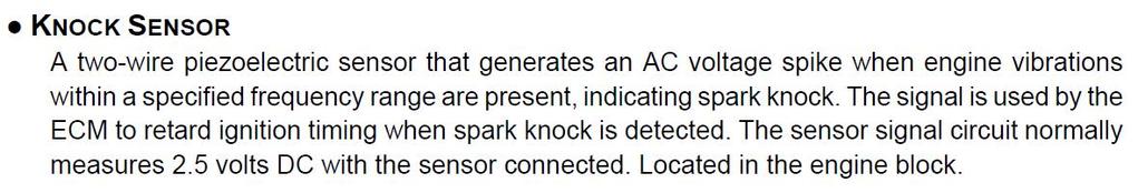
11 Chapter 26 Information #19 Thermistors as Sensors (ECT & IAT & TFT) #20 Pressure Sensors (piezo resistive) #23 MAF Sensor is a wheatstone bridge #25 Normal MAF is 4 7 gm/sec #26 #32 Oxygen Sensors!! Zirconic vs. Titanium #33 TPS & APP are Potentiometers #37 CKP & CMP are often Hall effect sensors #39 Knock Sensor (piezo generator)
12 Chapter 26 Information #40 Actuators & what they do Outputs controlled by the PCM include devices such as: Solenoids Relays Motors Lights Diagnostics (DTCs) These components control the operation of systems such as: A/C Compressor Clutch AIR Cruise Control MIL EVAP EGR Idle Air Control Cooling Fan Diagnostics (DTCs) Engine Torque Mgmt Fuel Pump Fuel Injector(s) Ignition Control Manifold Tuning Shift Light Throttle Control Torque Converter Clutch Transmission Shift Transmission Pressure


13 Chapter 32 Information #3 Definition of Vacuum #6 Normal Engine Vacuum Readings #9 14 Intake manifolds & variations


14 Chapter 32 Information #20 Super charging & Turbo charging #25 Turbo lag #26 Waste Gate #37 Super charger clutch


15 Chapter 32 Information #46 50 Catalytic Converters #53 Exhaust Back Pressure

16 Chapter 33 Information #2 HC #3 CO #4 NOx #9 Water in the exhaust is normal! HC CO NOx Unburned fuel All petroleum products Produced by incomplete combustion or fuel evaporation Extremely toxic Colorless and odorless Prevents blood cells from carrying oxygen to body tissues Caused by rich air fuel mixtures Air consists of 79% nitrogen and 21% oxygen Above approximately 2500 ºF, 1370 ºC, nitrogen and oxygen combine Caused by high compression ratio, lean burning, high operating temps
17 Chapter 33 Information #14 The Chart Initials Full Name Type Pollutants Lowered TAC Thermostatic Air Cleaner pre combustion HC CO NOx EGR Exhaust Gas Recirculation pre combustion HC CO NOx EVAP Evaporative System evaporative HC CO NOx EFE Early Fuel Evaporation pre combustion HC CO NOx ~~~~~~ CAT Catalytic Converter post combustion HC CO NOx AIR Air Injection System post combustion HC CO NOx PCV Positive Crankcase Ventilation post combustion HC CO NOx


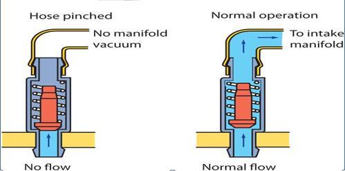
18 Chapter 33 Information #15 18 EVAP System Canister #21 24 PCV System PCV Valve #25 29 EGR System EGR Valve


19 Chapter 33 Information #30 EFE was used on Carburetors & TBI #32 34 Catalytic Converter Operation/Theory

20 Chapter 33 Information #35 37 Secondary Air Systems

21 Chapter 33 Information #38 43 Clean Diesels, Common Rail Injection #44 48 Diesel Exhaust After Treatment

22 Chapter 33 Information #38 43 Clean Diesels, Common Rail Injection #44 48 Diesel Exhaust After Treatment
23 Chapter 34 Information #1 Engine efficiency & pollution #2 There will always be some exhaust pollution #3 Common Exhaust Pollutants

24 Chapter 34 Information #4 5 IM 240 Testing under load #6 Cut points
25 Chapter 34 Information #9 Stoichiometric = Lambda #10 Before Diagnosis #11 Continuous & Non Continuous Monitors Readiness Monitors are Computer Self Tests that will Generate DTC s for Failures


26 Chapter 34 Information #11 Continuous & Non Continuous Monitors Readiness Monitors must be completed & passed in order to pass a DMV Emission Test!!
27 Chapter 34 Information #12 15 EVAP Testing #16 23 PCV Testing


28 Chapter 34 Information #24 27 EGR Testing Bi Directional or Activation Tests Using the Scan Tool

29 Chapter 34 Information #28 32 Catalytic Converter Testing


30 Chapter 34 Information #33 35 AIR (Secondary Air) Testing Bi Directional or Activation Tests Using the Scan Tool


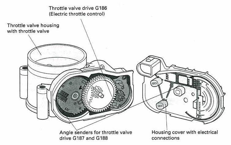
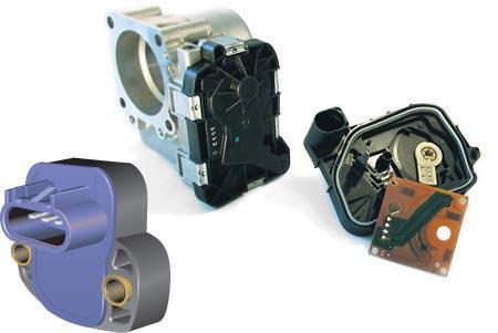
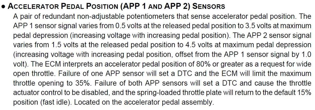
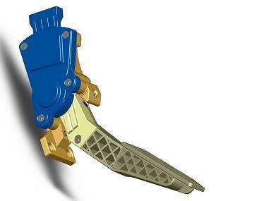
31 Great Stuff To Know Throttle Actuator Motor Accelerator Pedal Position Sensor Throttle by Wire System

32 Great Stuff To Know Throttle by Wire


 PID is a Parameter")
 Quad")
33 Great Stuff To Know Using TSB s to save time in diagnosis Why does a CAT get hotter? (chemical reaction!) PID is a Parameter Identifier (abbreviation) Quad Driver = Huge Switching Transistor
34 Know Your Sensors!!
35 Know Your Definitions!!

36 Know Your Pollutants!!


37 Know Your Emission Controls!! CAT, AIR, PCV, TAC, EVAP, EGR, EFE

38 Catalytic Converter Remedy/Post Combustion HC, CO, NOx
39 AIR Injection or Secondary Air System Remedy/Post Combustion HC & CO

40 Positive Crankcase Ventilation Remedy/Post Combustion HC & CO
41 Thermostatic Air Cleaner Pre Combustion Control HC & CO Goal is 80º to 120º Incoming Air Temp
42 Evaporative System Fuel Evaporation Control HC

43 Exhaust Gas Recirculation Pre Combustion Control (cools the burn) NOx

44 Early Fuel Evaporation Pre Combustion HC & CO Carburetor & TBI
45 Electronic Engine Control System Block Diagram
46 ABS Chassis SRS HVAC Anti Theft Body Scan Tool Sensors Inputs PCM DLC HO2S MIL TPS ECT Engine Outputs Actuators Ignition Spark IAT MAF MAP CKP CMP Open Loop Mode Closed Loop Mode Clear Flood Mode Limp In Mode EFI Emission Controls Cruise Accessories P/N KS VSS Electronic Engine Control System Block Diagram
47 Sensors Upstream (A/F) & Downstream (CAT) HO2S TPS ECT IAT MAF MAP CKP CMP P/N ABS Chassis Inputs SRS HVAC Anti Theft PCM PROM & RAM Engine Open Loop Mode Closed Loop Mode Clear Flood Mode Limp In Mode Outputs Body DLC MIL Actuators Ignition Spark EFI (injectors & IAC) Emission Controls (6) CAT AIR PCV TAC EVAP EGR Cruise Scan Tool DTC s Accessories Instrument Cluster KS VSS Electronic Engine Control System Block Diagram

48
49
50
51
52
53
54
55
ATASA 5 th. Detailed Diagnosis & Sensors. Please Read The Summary
 ATASA 5 TH Study Guide Chapter 26 Pages 764 809 51 Points Please Read The Summary 1. Many different sensors are involved in the overall driveability of a vehicle. Input Processing Output Electronic Engine
ATASA 5 th. Engine Performance Systems. Please Read The Summary. ATASA 5 TH Study Guide Chapter 25 Pages Engine Performance Systems 100 Points
 ATASA 5 TH Study Guide Chapter 25 Pages 725 763 100 Points Please Read The Summary 1. Engine systems are those responsible for how an engine runs. Performance Emission Control Electronic 2. The correct
Diagnostic Trouble Code (DTC) List - Vehicle
 List - Vehicle") Document ID# 850406 2002 Pontiac Firebird Diagnostic Trouble Code (DTC) List - Vehicle DTC DTC 021 and/or 031 DTC 022 and/or 032 DTC 023 or 033 DTC 24/34 DTC 025 and/or 035 DTC 041 DTC 042 DTC 043 DTC
Document ID# 850406 2002 Pontiac Firebird Diagnostic Trouble Code (DTC) List - Vehicle DTC DTC 021 and/or 031 DTC 022 and/or 032 DTC 023 or 033 DTC 24/34 DTC 025 and/or 035 DTC 041 DTC 042 DTC 043 DTC
Powertrain DTC Summaries EOBD
 Powertrain DTC Summaries Quick Reference Diagnostic Guide Jaguar S-TYPE V6, V8 N/A and V8 SC 2002.5 Model Year Refer to pages 2 9 for important information regarding the use of Powertrain DTC Summaries.
Powertrain DTC Summaries EOBD
 Powertrain DTC Summaries Quick Reference Diagnostic Guide Jaguar X-TYPE 2.0 L 2002.25 Model Year Refer to page 2 for important information regarding the use of Powertrain DTC Summaries. Jaguar X-TYPE 2.0
Powertrain DTC Summaries OBD II
 Powertrain DTC Summaries Quick Reference Diagnostic Guide Jaguar X-TYPE 2.5L and 3.0L 2002 Model Year Revised January, 2002: P0706, P0731, P0732, P0733, P0734, P0735, P0740, P1780 POSSIBLE CAUSES Revised
Powertrain DTC Summaries EOBD
 Powertrain DTC Summaries Quick Reference Diagnostic Guide Jaguar X-TYPE 2.5L and 3.0L 2001.5 Model Year Revised January, 2002: P0706, P0731, P0732, P0733, P0734, P0735, P0740, P1780 POSSIBLE CAUSES Revised
DTC P0174 Fuel Trim System Lean Bank 2
 2000 Chevrolet/Geo S10 Pickup - 4WD DTC P0174 Fuel Trim System Lean Bank 2 Circuit Description In order to provide the best possible combination of driveability, fuel economy, and emission control, the
For Troubleshooting of DTC related components, see chart on page INTAKE AIR BYPASS (IAB) HIGH CONTROL SOLENOID
 HIGH CONTROL SOLENOID") Index For Troubleshooting of DTC related components, see chart on page 11-53. '96-99 models: EXHAUST GAS RECIRCULATION (EGR) and LIFT MANIFOLD ABSOLUTE PRESSURE (MAP) INTAKE AIR BYPASS (IAB) HIGH page
Index For Troubleshooting of DTC related components, see chart on page 11-53. '96-99 models: EXHAUST GAS RECIRCULATION (EGR) and LIFT MANIFOLD ABSOLUTE PRESSURE (MAP) INTAKE AIR BYPASS (IAB) HIGH page
01 02B ON-BOARD DIAGNOSTIC [ENGINE CONTROL SYSTEM (FS)]
![01 02B ON-BOARD DIAGNOSTIC [ENGINE CONTROL SYSTEM (FS)]](/thumbs/80/80600627.jpg "01 02B ON-BOARD DIAGNOSTIC [ENGINE CONTROL SYSTEM (FS)]") ON-BOARD DIAGNOSTIC [ENGINE CONTROL SYSTEM (FS)] CONTROL SYSTEM WIRING DIAGRAM [FS]............................ 2 CONTROL SYSTEM DEVICE AND CONTROL RELATIONSHIP CHART [FS]........ 4 Engine Control System............
ON-BOARD DIAGNOSTIC [ENGINE CONTROL SYSTEM (FS)] CONTROL SYSTEM WIRING DIAGRAM [FS]............................ 2 CONTROL SYSTEM DEVICE AND CONTROL RELATIONSHIP CHART [FS]........ 4 Engine Control System............
ENGINE 01 02A 1. Toc of SCT ON-BOARD DIAGNOSTIC [ENGINE. Toc of SCT 01 02A ON-BOARD DIAGNOSTIC [ENGINE CONTROL SYSTEM (ZM)] 01 02A
![ENGINE 01 02A 1. Toc of SCT ON-BOARD DIAGNOSTIC [ENGINE. Toc of SCT 01 02A ON-BOARD DIAGNOSTIC [ENGINE CONTROL SYSTEM (ZM)] 01 02A](/thumbs/90/103285807.jpg "ENGINE 01 02A 1. Toc of SCT ON-BOARD DIAGNOSTIC [ENGINE. Toc of SCT 01 02A ON-BOARD DIAGNOSTIC [ENGINE CONTROL SYSTEM (ZM)] 01 02A") ENGINE 01 SECTION Toc of SCT ON-BOARD DIAGNOSTIC [ENGINE CONTROL SYSTEM (ZM)]...01-02A ON-BOARD DIAGNOSTIC [ENGINE CONTROL SYSTEM (FS)]...01-02B ON-BOARD DIAGNOSTIC [CRUISE CONTROL SYSTEM].......01-02C
ENGINE 01 SECTION Toc of SCT ON-BOARD DIAGNOSTIC [ENGINE CONTROL SYSTEM (ZM)]...01-02A ON-BOARD DIAGNOSTIC [ENGINE CONTROL SYSTEM (FS)]...01-02B ON-BOARD DIAGNOSTIC [CRUISE CONTROL SYSTEM].......01-02C
VOLKS CITY BEECH AVENUE CATTEDOWN PLYMOUTH PL4 0QQ
 VOLKS CITY BEECH AVENUE CATTEDOWN PLYMOUTH PL4 0QQ Telephone: 01752 667007 Fax: 01752 663399 Email: mail@volkscity.com 1 Camshaft position (CMP) sensor 1 2 Camshaft position (CMP) sensor 2 3 Camshaft position
Diagnostic Trouble Code (DTC) table
 table") Page 1 of 40 01-19 Diagnostic Trouble Code (DTC) table Note: When malfunctions occur in monitored sensors or components, Diagnostic Trouble Codes (DTCs) are stored in DTC memory with a description of the
Page 1 of 40 01-19 Diagnostic Trouble Code (DTC) table Note: When malfunctions occur in monitored sensors or components, Diagnostic Trouble Codes (DTCs) are stored in DTC memory with a description of the
Service Bulletin. DTC Detection Item Associated Monitor
 Service Bulletin 03-010 Applies To: All OBD II equipped models except SLX March 29, 2003 OBD II DTCs and Their Associated Monitors This is a list of all DTCs for all OBD II models. No one model has all
DTC Summaries. NipponDenso V12 Engine Management
 DTC Summaries NipponDenso V12 Engine Management OBD II MONITORING CONDITIONS: When testing for DTC reoccurrence, it can be determined if the Service Drive Cycle was of sufficient length by performing a
Diagnostic Trouble Code (DTC) memory, checking and erasing
 memory, checking and erasing") Page 1 of 49 01-12 Diagnostic Trouble Code (DTC) memory, checking and erasing Check DTC Memory (function 02) - Connect VAS5051 tester Page 01-7 and select vehicle system "01 - Engine electronics". Engine
Page 1 of 49 01-12 Diagnostic Trouble Code (DTC) memory, checking and erasing Check DTC Memory (function 02) - Connect VAS5051 tester Page 01-7 and select vehicle system "01 - Engine electronics". Engine
2.8 Liter VR6 2V Fuel Injection & Ignition, Engine Code(s): AAA m.y
: AAA m.y") 2.8 Liter VR6 2V Fuel Injection & Ignition, Engine Code(s): AAA m.y. 1996-1997 01 - On Board Diagnostic (OBD) On Board Diagnostic (OBD II) Malfunction Indicator Lamp (MIL) On Board Diagnostic (OBD II),
2.8 Liter VR6 2V Fuel Injection & Ignition, Engine Code(s): AAA m.y. 1996-1997 01 - On Board Diagnostic (OBD) On Board Diagnostic (OBD II) Malfunction Indicator Lamp (MIL) On Board Diagnostic (OBD II),
Diagnostic Trouble Codes (continued) GM Specific Codes
 GM Specific Codes") 85 GM Specific Codes P11XX Fuel and Air Metering P1106 MAP Sensor Circuit Intermittent High Voltage P1107 MAP Sensor Circuit Intermittent Low Voltage P1108 BARO to MAP Signal Comparison Too High P1111
85 GM Specific Codes P11XX Fuel and Air Metering P1106 MAP Sensor Circuit Intermittent High Voltage P1107 MAP Sensor Circuit Intermittent Low Voltage P1108 BARO to MAP Signal Comparison Too High P1111
Telephone: Fax: VAT Registration No.:
 Telephone: Fax: VAT Registration No.: Terminal side Wire side Component/circuit description ECM pin Signal Condition Typical value Oscilloscope setting (Suggested settings - Voltage/time per division)
GM Enhanced Parameters
 GM Enhanced Parameters # of 4x Ref Pulses between CAM Counter # OF EGR ADAPTIVE LEARN MATRIX CELLS OUT OF RANGE High # OF EGR ADAPTIVE LEARN MATRIX CELLS OUT OF RANGE LOW 1-2 Adapt High Cell 1-2 Adapt
ELECTRONIC ENGINE CONTROLS
 2005 Jaguar S-Type (X200) V8-4.2L Vehicle > Powertrain Management > Computers and Control Systems > Description and Operation > Components ELECTRONIC ENGINE CONTROLS Electronic Engine Controls Vehicles
DTC P1415 Secondary Air Injection (AIR) System Bank 1
 System Bank 1") Page 1 of 5 2000 GMC Truck GMC K Sierra - 4WD Sierra, Silverado, Suburban, Tahoe, Yukon (VIN C/K) Service Manual Document ID: 546887 DTC P1415 Secondary Air Injection (AIR) System Bank 1 Circuit Description
Page 1 of 5 2000 GMC Truck GMC K Sierra - 4WD Sierra, Silverado, Suburban, Tahoe, Yukon (VIN C/K) Service Manual Document ID: 546887 DTC P1415 Secondary Air Injection (AIR) System Bank 1 Circuit Description
2002 ENGINE PERFORMANCE. Self-Diagnostics - RAV4. Before performing testing procedures, check for any related Technical Service Bulletins (TSBs).
.") 2002 ENGINE PERFORMANCE Self-Diagnostics - RAV4 INTRODUCTION NOTE: Before performing testing procedures, check for any related Technical Service Bulletins (TSBs). To properly diagnosis and repair this
2002 ENGINE PERFORMANCE Self-Diagnostics - RAV4 INTRODUCTION NOTE: Before performing testing procedures, check for any related Technical Service Bulletins (TSBs). To properly diagnosis and repair this
DIAGNOSTIC TROUBLE CODE CHART
 DI158 DIAGNOSTIC TROUBLE CODE CHART HINT: ENGINE (2JZGTE) Parameters listed in the chart may not be exactly the same as your reading due to the type of instrument or other factors. If a malfunction code
SECONDARY PARAMETERS AND ENABLE CONDITIONS
 SECONDARY S AND Manifold Pressure Sensor Rationality Manifold Pressure Too Low Manifold Pressure Too High Intake Air Temperature Sensor Shorted Intake Air Temperature Sensor Open Coolant Temperature Sensor
Emissions Theory and Diagnostics
 SECTION 1 Introduction 5-Gas Theory Emissions History OBD II SECTION 2 PCV System Function Failure Diagnosis Emissions Theory and Diagnostics SECTION 3 EGR EGR Theory Vacuum Systems Backpressure Systems
Telephone: Fax: VAT Registration No.:
 Telephone: Fax: VAT Registration No.: Name: Manufacturer: Ford Address: Model: Year: 1994 Registration: Tel - Private: Tel - Business: Mileage: Job number: Terminal side Wire side Component/circuit description
Scan Tool Test Procedures Steve Zack Technical Instructor Bosch AA-AS
 Scan Tool Test Procedures Steve Zack Technical Instructor Bosch AA-AS Steve Zack 8.10.15 1 This class will develop the technician skills to use their scan tool to resolve difficult technical issues efficiently.
cylinder cars / trucks (except Saturn S-series cars) ENGINE DIAGNOSTIC PARAMETERS
 ENGINE DIAGNOSTIC PARAMETERS") 2001 4-cylinder cars / trucks (except Saturn S-series cars) ENGINE DIAGNOSTIC S SECONDARY S AND Manifold Pressure/Throttle Position Sensor Manifold Pressure/Throttle Position Sensor Manifold Pressure Too
2001 4-cylinder cars / trucks (except Saturn S-series cars) ENGINE DIAGNOSTIC S SECONDARY S AND Manifold Pressure/Throttle Position Sensor Manifold Pressure/Throttle Position Sensor Manifold Pressure Too
MERCEDES P1XXX CODES Gas and Diesel
 MERCEDES P1XXX CODES 4/27/2000 Gasoline Engines Mercedes Pcode P0801 P1031 P1131 P1132 P1137 P1138 P1146 MERCEDES P1XXX CODES Gas and Diesel OBD-II Pcode Definition Engine/Climate control electric cooling
DIAGNOSTIC TROUBLE CODE CHART HINT:
 DIAGNOSTICS DIAGNOSTIC TROUBLE CODE CHART HINT: SFI SYSTEM (1MZFE) 05241 Parameters listed in the chart may not be exactly the same as your reading due to the type of instrument or other factors. If a
Diagnostic Trouble Codes (continued) Ford Specific Codes
 Ford Specific Codes") 92 Ford Specific Codes P11XX Fuel and Air Metering P1000 OBD-II Monitor Drive Cycle Not Completed P1001 KOER Self-Test Not Completed, Test Aborted P1100 Mass Airflow MAF Sensor Intermittent P1101 Mass
92 Ford Specific Codes P11XX Fuel and Air Metering P1000 OBD-II Monitor Drive Cycle Not Completed P1001 KOER Self-Test Not Completed, Test Aborted P1100 Mass Airflow MAF Sensor Intermittent P1101 Mass
C6 Corvette DIC Codes
 C6 Corvette DIC Codes B0159 Outside Air Temp Sensor B2910 Steering Column Lock Password Incorrect B0164 Pass Compartment Temp Sensor B2981 Right Front Door Handle Switch B0174 Output Air Temp Sensor 1
DTC P0171, P0172, P0174, or P0175
 Page 1 of 6 2009 Pontiac G8 G8 Service Manual Document ID: 2076050 DTC P0171, P0172, P0174, or P0175 Diagnostic Instructions Perform the Diagnostic System Check - Vehicle prior to using this diagnostic
 Verified Fix #1 Tool Data Diagnostic Trouble Code Information Report Customer #1 VIN: JT8BL69SX4G015327 Customer Name: Year: 2004 Customer Phone#: 123-123-1234 Make: Lexus Report#: 162 Model: GS 430 Date
Component Locations. Index. D16Y5 engine: Note: For troubleshooting of DTC related components see chart on page THROTTLE POSITION (TP) SENSOR
 SENSOR") Index Note: For troubleshooting of DTC related components see chart on page 11-97. D16Y5 engine: THROTTLE POSITION (TP) MANIFOLD ABSOLUTE PRESSURE (MAP) EXHAUST GAS RECIRCULATION (EGR) VALVE and EXHAUST
Index Note: For troubleshooting of DTC related components see chart on page 11-97. D16Y5 engine: THROTTLE POSITION (TP) MANIFOLD ABSOLUTE PRESSURE (MAP) EXHAUST GAS RECIRCULATION (EGR) VALVE and EXHAUST
Five-digit error code First position: P - is for powertrain codes B - is for body codes C - is for chassis codes
 https://www.automotive-manuals.net Five-digit error code First position: P - is for powertrain codes B - is for body codes C - is for chassis codes The second position: 0 - the total for the OBD-II code
Chapter 20 OBD-II Diesel Monitors
 Light Vehicle Diesel Engines First Edition Chapter 20 OBD-II Diesel Monitors LEARNING OBJECTIVES (1 of 2) 20.1 Prepare for the Light Vehicle Diesel Engine (A9) ASE certification fuel system diagnosis and
E - THEORY/OPERATION - TURBO
 E - THEORY/OPERATION - TURBO 1995 Volvo 850 1995 ENGINE PERFORMANCE Volvo - Theory & Operation 850 - Turbo INTRODUCTION This article covers basic description and operation of engine performance-related
ARTICLE BEGINNING INTRODUCTION SELF-DIAGNOSTIC SYSTEM RETRIEVING DTCS ENGINE PERFORMANCE Volkswagen Self-Diagnostics - Gasoline
 Article Text ARTICLE BEGINNING 1996 ENGINE PERFORMANCE Volkswagen Self-Diagnostics - Gasoline Cabrio, Golf III, GTI, Jetta III, Passat INTRODUCTION If no faults were found while performing preliminary
2UZ-FE ENGINE CONTROL SYSTEM SFI SYSTEM
 160 2UZ-FE EINE CONTROL SYSTEM SFI SYSTEM DTC P0171 System Too Lean (Bank 1) DTC P0172 System Too Rich (Bank 1) DTC P0174 System Too Lean (Bank 2) DTC P0175 System Too Rich (Bank 2) DCRIPTION The fuel
ATASA 5 th. ATASA 5 TH Study Guide Chapter 31 Pages EFI Diagnosis & Service 47 Points. Please Read The Summary
 ATASA 5 TH Study Guide Chapter 31 Pages 922 948 47 Points Please Read The Summary 1. Troubleshooting EFI systems requires step by step test procedures mostly due to the many interrelated components and
OBD-II Diagnostic Powertrain (P) Trouble Codes
 Trouble Codes") OBD-II Diagnostic Powertrain (P) Trouble Codes Please use our new & improved search engine to find information on your trouble codes. Search Now! This list contains standard diagnostic trouble codes (DTC
OBD-II Diagnostic Powertrain (P) Trouble Codes Please use our new & improved search engine to find information on your trouble codes. Search Now! This list contains standard diagnostic trouble codes (DTC
Zoom and Print Options
 Vehicle» Engine, Cooling and Exhaust» Engine» Service and Repair» Removal and Replacement» Engine Replacement Engine Replacement ^ Tools Required - J 38185 Hose Clamp Pliers Removal Procedure 1. Remove
1GR-FE ENGINE CONTROL SYSTEM SFI SYSTEM
 134 1GR-FE EINE CONTROL SYSTEM SFI SYSTEM DTC P0136 Oxygen Sensor Circuit Malfunction (ank 1 Sensor ) DTC P0137 Oxygen Sensor Circuit Low Voltage (ank 1 Sensor ) DTC P0138 Oxygen Sensor Circuit High Voltage
(P0135/P0155), (P0141/P0161), (P1131/P1151), (P1132/P1152). To further clarify this, see the more detailed scenario as follows:
, (P0141/P0161), (P1131/P1151), (P1132/P1152). To further clarify this, see the more detailed scenario as follows:") 1. Always reset KAM after performing a repair: After performing a repair on a vehicle with the MIL on, and/or DTCs present, always clear KAM. When a malfunction is present, the PCM adapts (attempts to
1. Always reset KAM after performing a repair: After performing a repair on a vehicle with the MIL on, and/or DTCs present, always clear KAM. When a malfunction is present, the PCM adapts (attempts to
DIAGNOSTIC TROUBLE CODE CHART
 DIAGNOSTIC TROUBLE CODE CHART HINT: DI231 Parameters listed in the chart may not be exactly the same as your readings due to the type of instrument or other factors. If a malfunction code is displayed
GROUP 13Ab. 13Ab-2 CONTENTS TROUBLESHOOTING STRATEGY.. DATA LIST REFERENCE TABLE... 13Ab-29 TROUBLE CODE DIAGNOSIS...
 13Ab-1 GROUP 13Ab CONTENTS TROUBLESHOOTING STRATEGY.. 13Ab-2 DATA LIST REFERENCE TABLE... 13Ab-29 TROUBLE CODE DIAGNOSIS..... 13Ab-2 FAIL-SAFE FUNCTION REFERENCE TABLE........................ 13Ab-20 DIAGNOSTIC
C5 Computer Diagnostic Codes
 C5 Computer Diagnostic Codes The ability to view engine operating data such as oil pressure and coolant temperature, in digital form on the instrument panel has been a feature of Corvettes since 1984.
DTC P0172 Fuel Trim System Rich
 Page 1 of 6 1997 Chevrolet Cavalier Cavalier, Sunfire (VIN J) Service Manual Document ID: 47788 DTC P0172 Fuel Trim System Rich System Description A Closed Loop air/fuel metering system is used to provide
1. Connect the Honda PGM Tester or an OBD II scan tool to the 16P Data Link Connector (DLC) located behind the right side of the center console.
 located behind the right side of the center console.") Troubleshooting Procedures I. How To Begin Troubleshooting When the Malfunction indicator Lamp (MIL) has been reported on, or there is a driveability problem, use the appropriate procedure below to diagnose
Troubleshooting Procedures I. How To Begin Troubleshooting When the Malfunction indicator Lamp (MIL) has been reported on, or there is a driveability problem, use the appropriate procedure below to diagnose
2009 PCED Gasoline Engines SECTION 1: Description and Operation. Intake Air System
 2009 PCED Gasoline Engines SECTION 1: Description and Operation Procedure revision date: 05/27/2010 Overview Intake Air Systems The intake air system provides clean air to the engine, optimizes air flow,
JACKAROO TIPS Understanding the MIL fault codes on a Jackaroo Turbo Diesel
 JACKAROO TIPS Understanding the MIL fault codes on a Jackaroo Turbo Diesel The Jackaroo, as with all vehicles intended to be supplied to the USA market, (as the Isuzu Trooper) is fitted with OnBoard Diagnostics
5. Control System CONTROL SYSTEM FUEL INJECTION (FUEL SYSTEM) A: GENERAL FU(H4DOTC)-29
 A: GENERAL FU(H4DOTC)-29") W1860BE.book Page 29 Tuesday, January 28, 2003 11:01 PM 5. Control System A: GENERAL The ECM receives signals from various sensors, switches, and other control modules. Using these signals, it determines
W1860BE.book Page 29 Tuesday, January 28, 2003 11:01 PM 5. Control System A: GENERAL The ECM receives signals from various sensors, switches, and other control modules. Using these signals, it determines
UIF Technology CO.,LTD.
 CONTENTS 1. INTRODUCTION MEMOScanner is newly developed by UIF TECH, specially designed for car owners or DIYs. With an MEMOScanner, you may quickly find out trouble causes of electronically controlled
Lower Intake Manifold Replacement
 Lower Intake Manifold Replacement Removal Procedure 1. Turn OFF all the lamps and the accessories. 2. Ensure the ignition switch is in the OFF position. 3. Disconnect the negative battery cable from the
EMISSION CONTROL (AUX. EMISSION CONTROL DEVICES) H4SO
 H4SO") EMISSION CONTROL (AUX. EMISSION CONTROL DEVICES) H4SO SYSTEM OVERVIEW 1. System Overview There are three emission control systems, which are as follows: Crankcase emission control system Exhaust emission
EMISSION CONTROL (AUX. EMISSION CONTROL DEVICES) H4SO SYSTEM OVERVIEW 1. System Overview There are three emission control systems, which are as follows: Crankcase emission control system Exhaust emission
Model Year: 2007 Model: Tacoma Doc ID: RM H800NX
 Page 1 of 12 Last Modified: 5-7-2008 5.1 C From: 200608 Model Year: 2007 Model: Tacoma Doc ID: RM0000013H800NX Title: 2TR-FE ENGINE CONTROL SYSTEM: SFI SYSTEM: P2A00: A/F Sensor Circuit Slow Response (Bank
G - TESTS W/CODES - 2.2L
 G - TESTS W/CODES - 2.2L 1994 Toyota Celica 1994 ENGINE PERFORMANCE Toyota 2.2L Self-Diagnostics Celica INTRODUCTION If no faults were found while performing F - BASIC TESTING, proceed with self-diagnostics.
DIAGNOSTIC TROUBLE CODE DEFINITIONS
 DIAGNOSTIC TROUBLE CODE DEFINITIONS DIAGNOSTIC TROUBLE CODE DEFINITIONS DTC Description P0010 Variable Valve Timing Circuit Malfunction (Bank 1) P0020 Variable Valve Timing Circuit Malfunction (Bank 2)
Disconnect the breather tube from the air cleaner outlet duct.
 Disconnect the breather tube from the air cleaner outlet duct. Disconnect the IAT sensor harness connector. Remove the air cleaner outlet duct retaining wingnut. Separate the air cleaner outlet duct from
5. Control System CONTROL SYSTEM FUEL INJECTION (FUEL SYSTEM) A: GENERAL. FU(STi)-27
 A: GENERAL. FU(STi)-27") W1860BE.book Page 27 Tuesday, January 28, 2003 11:01 PM 5. Control System A: GENERAL The ECM receives signals from various sensors, switches, and other control modules. Using these signals, it determines
W1860BE.book Page 27 Tuesday, January 28, 2003 11:01 PM 5. Control System A: GENERAL The ECM receives signals from various sensors, switches, and other control modules. Using these signals, it determines
OBD II Data Interpretation
 OBD II Data Interpretation What is OBDII? OBDII stands for on board diagnostics second generation superseding that of OBD1.OBDII is a system that was mandated by the Federal EPA and was developed by the
SECTION 1F ENGINE CONTROLS
 SECTION 1F ENGINE CONTROLS CAUTION: Disconnect the negative battery cable before removing or installing any electrical unit or when a tool or equipment could easily come in contact with exposed electrical
2UZ-FE ENGINE CONTROL SYSTEM SFI SYSTEM
 385 P2237 / Open (Bank 1 Sensor 1) P2238 Low (Bank 1 Sensor 1) P2239 High (Bank 1 Sensor 1) P2240 P2241 / Open (Bank 2 Sensor 1) Low (Bank 2 Sensor 1) P2242 High (Bank 2 Sensor 1) P2252 Low (Bank 1 Sensor
GROUP 13Ab. 13Ab-2 CONTENTS TROUBLESHOOTING STRATEGY.. DATA LIST REFERENCE TABLE... 13Ab-28 TROUBLE CODE DIAGNOSIS...
 13Ab-1 GROUP 13Ab CONTENTS TROUBLESHOOTING STRATEGY.. 13Ab-2 DATA LIST REFERENCE TABLE... 13Ab-28 TROUBLE CODE DIAGNOSIS..... 13Ab-2 FAIL-SAFE/BACKUP FUNCTION TABLE........................ 13Ab-20 DIAGNOSTIC
L (LL8) Engine Diagnostic Parameters
 Engine Diagnostic Parameters") Cam Shaft Position Actuator Control VCP System Performance VCP = variable cam phaser VCP Crank/Cam Correlation Error P0013 P0014 P0016 DESCRIPTION Detects an open or shorted control circuit by monitoring
Cam Shaft Position Actuator Control VCP System Performance VCP = variable cam phaser VCP Crank/Cam Correlation Error P0013 P0014 P0016 DESCRIPTION Detects an open or shorted control circuit by monitoring
 Page 1 of 18 2004 PCED On Board Diagnostics SECTION 5: Pinpoint Tests Procedure revision date: 10/26/2007 H: Fuel Control H: Introduction H1 PERFORM THE KOER SELF-TEST Engine at normal operating temperature.
9. Subaru Select Monitor
 9. A: OPERATION 1. HOW TO USE SUBARU SELECT MONI- TOR 1) Prepare the kit. CAUTION: Do not connect the scan tools except for Subaru Select
EMISSION CONTROL (AUX. EMISSION CONTROL DEVICES) H4DOTC
 H4DOTC") EMISSION CONTROL (AUX. EMISSION CONTROL DEVICES) H4DOTC SYSTEM OVERVIEW 1. System Overview There are three emission control systems, which are as follows: Crankcase emission control system Exhaust emission
EMISSION CONTROL (AUX. EMISSION CONTROL DEVICES) H4DOTC SYSTEM OVERVIEW 1. System Overview There are three emission control systems, which are as follows: Crankcase emission control system Exhaust emission
EMISSION CONTROL VISUAL INSPECTION PROCEDURES
 EMISSION CONTROL VISUAL INSPECTION PROCEDURES 1992 Infiniti G20 1983-98 GENERAL INFORMATION Emission Control Visual Inspection Procedures All Models * PLEASE READ THIS FIRST * This article is provided
Motronic September 1998
 The Motronic 1.8 engine management system was introduced with the 1992 Volvo 960. The primary difference between this Motronic system and the previous generation of Volvo LH-Jetronic engine management
For. Code Reader. User Manual
 For OBD2 Code Reader User Manual http://www.motodok.com Table of Contents 1. Description... 2 2. Features... 2 3. Getting Started... 3 1. Connect Code Reader to Vehicle's Test Connector... 3 2. Read Diagnostic
L (LU4, LJ3, L88) used in Saab 9-5 ENGINE DIAGNOSTIC PARAMETERS
 used in Saab 9-5 ENGINE DIAGNOSTIC PARAMETERS") Catalytic Converter Monitoring P0420 Front vs. Rear O2 sensor signal Evaluated data 1,75 times FTP std 80 (unitless) Coolant temp Throttle Delta load, positive Delta load, negative Engine speed, man. trans
Catalytic Converter Monitoring P0420 Front vs. Rear O2 sensor signal Evaluated data 1,75 times FTP std 80 (unitless) Coolant temp Throttle Delta load, positive Delta load, negative Engine speed, man. trans
Audi > B4 > Liter V6 2V Engine Mechanical, Engine Code(s): AAH, AFC 10 Engine Assembly
: AAH, AFC 10 Engine Assembly") Audi > B4 > 1993 1995 2.8 Liter V6 2V Engine Mechanical, Engine Code(s): AAH, AFC 10 Engine Assembly Removing The engine is removed from above, after being separated from the transmission. Note: All tie
Audi > B4 > 1993 1995 2.8 Liter V6 2V Engine Mechanical, Engine Code(s): AAH, AFC 10 Engine Assembly Removing The engine is removed from above, after being separated from the transmission. Note: All tie
Fuel Metering System Component Description
 1999 Chevrolet/Geo Tahoe - 4WD Fuel Metering System Component Description Purpose The function of the fuel metering system is to deliver the correct amount of fuel to the engine under all operating conditions.
 http://www.prodemand.com/print/index?content=tabs&module=true&tab=true&terms=t... Page of // 0 Chevrolet Traverse.L Eng LT Service Manual: WIRING DIAGRAMS Print Date: // ENGINE PERFORMANCE >.L VIN D Fig
7. Remove the starter motor. Refer to Starter Motor Replacement (2.2L) or Starter Motor Replacement (4.3L).
 or Starter Motor Replacement (4.3L).") 1 of 9 1/5/2013 6:40 PM Removal Procedure 1. Disconnect the battery negative cable. Refer to Battery Replacement. 2. Remove the hood. Refer to Hood Replacement. 3. If the vehicle is equipped with a manual
1 of 9 1/5/2013 6:40 PM Removal Procedure 1. Disconnect the battery negative cable. Refer to Battery Replacement. 2. Remove the hood. Refer to Hood Replacement. 3. If the vehicle is equipped with a manual
NATEF ENGINE PERFORMANCE CHECKLIST Name Date Period
 NATEF ENGINE PERFORMANCE CHECKLIST Name Period For every task in Engine Performance the following safety requirement must be strictly enforced: Comply with personal and environmental safety practices associated
Telephone: Fax: VAT Registration No.:
 Telephone: Fax: VAT Registration No.: K143 AC compressor clutch relay X88 AC connector S63 AC refrigerant pressure switch S341 AC refrigerant triple pressure switch A16 Anti-lock braking system (ABS) control
UNDERSTANDING 5 GAS DIAGNOSIS
 UNDERSTANDING 5 GAS DIAGNOSIS AND EMISSIONS Gas Diagnostic Steps This procedure will help in your efforts to figure out what the five-gas reading are telling you. In order for five gas analyses to be conclusive
E - THEORY/OPERATION ENGINE PERFORMANCE General Motors Corp. - Theory & Operation - 5.7L
 E - THEORY/OPERATION 1998 ENGINE PERFORMANCE General Motors Corp. - Theory & Operation - 5.7L INTRODUCTION This article covers basic description and operation of engine performance-related systems and
MULTIPOINT FUEL INJECTION (MPI) <4G63-Turbo>
 <4G63-Turbo>") 13B-1 GROUP 13B MULTIPOINT FUEL INJECTI (MPI) CTENTS GENERAL INFORMATI........ 13B-2 SENSOR....................... 13B-8 THROTTLE VALVE OPENING ANGLE CTROL.............. 13B-9 FUEL INJECTI
13B-1 GROUP 13B MULTIPOINT FUEL INJECTI (MPI) CTENTS GENERAL INFORMATI........ 13B-2 SENSOR....................... 13B-8 THROTTLE VALVE OPENING ANGLE CTROL.............. 13B-9 FUEL INJECTI
DTC P0171 SYSTEM TOO LEAN (BANK 1) DTC P0174 SYSTEM TOO LEAN (BANK 2)
 DTC P0174 SYSTEM TOO LEAN (BANK 2)") 05498 DIAGNOSTICS DTC P0171 SYSTEM TOO LEAN (BANK 1) 05EXR06 DTC P0172 SYSTEM TOO RICH (BANK 1) DTC P0174 SYSTEM TOO LEAN (BANK 2) DTC P0175 SYSTEM TOO RICH (BANK 2) CIRCUIT DESCRIPTION The fuel trim is
05498 DIAGNOSTICS DTC P0171 SYSTEM TOO LEAN (BANK 1) 05EXR06 DTC P0172 SYSTEM TOO RICH (BANK 1) DTC P0174 SYSTEM TOO LEAN (BANK 2) DTC P0175 SYSTEM TOO RICH (BANK 2) CIRCUIT DESCRIPTION The fuel trim is
C5 Corvette IPC Diagnostic Display Mode
 C5 Corvette IPC Diagnostic Display Mode The IPC display, the 20-character, vacuum florescent screen above the steering column that says "Corvette by Chevrolet" every time you turn on the key is a powerful
Diagnostic Trouble Code (DTC) Root Cause. for Omnitek ECM 64A/66A/88A. & Remedial Action
 Root Cause. for Omnitek ECM 64A/66A/88A. & Remedial Action") Diagnostic Trouble Code (DTC) Root Cause & Remedial Action for Omnitek ECM 64A/66A/88A Omnitek Engineering Corp. 1945 S Rancho Santa Fe Rd. San Marcos, CA 92078 Tel. 760-591-0089 - Fax. 760-591-0880 -
Diagnostic Trouble Code (DTC) Root Cause & Remedial Action for Omnitek ECM 64A/66A/88A Omnitek Engineering Corp. 1945 S Rancho Santa Fe Rd. San Marcos, CA 92078 Tel. 760-591-0089 - Fax. 760-591-0880 -
Engine management/transmission
 MAZDA Model: 323 (BG) 323 Estate 1,6/4x4 (BW) 323 (BA/BJ) 626/MX-6 626/Estate Xedos 6/9 MX-3/MX-5 Year: 1989-00 Engina code: BP, BP-DOHC, B3, B3E, B6, B6-SOHC, B6-DOHC, B6E,FP, FS, KF, KJ, KL K8, RF, RF-CX,
Cylinder Head Removal
 2006 Odyssey Cylinder Head Removal Report a problem with this article NOTE: Use fender covers to avoid damaging painted surfaces. To avoid damaging the wires and terminals, unplug the wiring connectors
Monitor item P0011 CMP-timing over-advanced ON 1 CCM P0012 CMP-timing over-retarded ON 2 CCM
 1 of 12 Mazda 3 OBD Codes Engine No. Condition MIL DC Monitor item P0011 CMP-timing over-advanced ON 1 CCM P0012 CMP-timing over-retarded ON 2 CCM P0031 Front HO2S heater control circuit low ON 2 HO2S
05/14/01 14 mai 2001 Emissions/Engine Controls - Driveability Diagnosis Index - Information - A. Description of Terms and Acronyms - B.
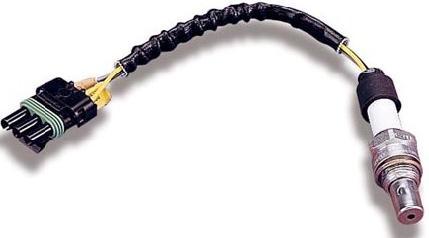
 Article No. 01-9-7 05/14/01 14 mai 2001 Emissions/Engine Controls - Driveability Diagnosis Index - Information - A. Description of Terms and Acronyms - B. HO2S Location Diagrams - C. Heated Oxygen Sensor
RODEO 2.2L ENGINE DRIVEABILITY AND EMISSIONS
 6E1 1 RODEO CONTROL SYSTEM RODEO 2.2L ENGINE DRIVEABILITY AND EMISSIONS CONTENTS SPECIFICATIONS...................... 6E1 6 TIGHTENING SPECIFICATIONS........ 6E1 6 DIAGRAMS AND SCHEMATICS.......... 6E1
9.6 ME-SFI (ME1.0) Engine 120
 Engine 120") Components on engine Model 129 Figure 1 B2/6 Left hot film MAF sensor (located on right side of engine) B2/7 Right hot film MAF sensor (located on left side of engine) B17/5 Left IAT sensor (located in
Components on engine Model 129 Figure 1 B2/6 Left hot film MAF sensor (located on right side of engine) B2/7 Right hot film MAF sensor (located on left side of engine) B17/5 Left IAT sensor (located in
MULTIPORT FUEL SYSTEM (MFI) <2.4L ENGINE>
 <2.4L ENGINE>") 13A-1 GROUP 13A MULTIPORT FUEL SYSTEM (MFI) CONTENTS GENERAL DESCRIPTION......... 13A-2 FUEL INJECTION CONTROL...... 13A-5 THROTTLE VALVE OPENING ANGLE CONTROL..................... 13A-6
13A-1 GROUP 13A MULTIPORT FUEL SYSTEM (MFI) CONTENTS GENERAL DESCRIPTION......... 13A-2 FUEL INJECTION CONTROL...... 13A-5 THROTTLE VALVE OPENING ANGLE CONTROL..................... 13A-6
DTC P0420 CATALYST SYSTEM EFFICIENCY BELOW THRESHOLD (BANK 1) DTC P0430 CATALYST SYSTEM EFFICIENCY BELOW THRESHOLD (BANK 2)
 DTC P0430 CATALYST SYSTEM EFFICIENCY BELOW THRESHOLD (BANK 2)") DIAGNOSTICS DTC P0420 CATALYST SYSTEM EFFICIENCY BELOW THRESHOLD (BANK 1) 05551 05BNU11 DTC P0430 CATALYST SYSTEM EFFICIENCY BELOW THRESHOLD (BANK 2) MONITOR DESCRIPTION The ECM uses sensors mounted before
DIAGNOSTICS DTC P0420 CATALYST SYSTEM EFFICIENCY BELOW THRESHOLD (BANK 1) 05551 05BNU11 DTC P0430 CATALYST SYSTEM EFFICIENCY BELOW THRESHOLD (BANK 2) MONITOR DESCRIPTION The ECM uses sensors mounted before
1.2 HFM Sequential Multiport Fuel injection/ignition System (HFM-SFI) Engine 111
 Engine 111") Preliminary work: Diagnosis - Malfunction Memory...................................... 11 Preparation for Test 1. Ignition: OFF 2. Connect test cable with socket box to engine control module (N3/4) according
Preliminary work: Diagnosis - Malfunction Memory...................................... 11 Preparation for Test 1. Ignition: OFF 2. Connect test cable with socket box to engine control module (N3/4) according
Lotus Service Notes Section EMD
 ENGINE MANAGEMENT SECTION EMD Lotus Techcentre Sub-Section Page Diagnostic Trouble Code List EMD.1 3 Component Function EMD.2 8 Component Location EMD.3 10 Diagnostic Guide EMD.4 11 CAN Bus Diagnostics;
P Fuel Volume Regulator Control Circuit P Fuel Volume Regulator Control Circuit Range/Performance P Fuel Volume Regulator Control
 P0001 - Fuel Volume Regulator Control Circuit P0002 - Fuel Volume Regulator Control Circuit Range/Performance P0003 - Fuel Volume Regulator Control Circuit Low P0004 - Fuel Volume Regulator Control Circuit
AD07.61-P-4000AC ME-SFI fuel injection and ignition system (ME), DTC memory Possible cause Note Fault code description
, DTC memory Possible cause Note Fault code description") Page 1 of 11 AD07.61-P-4000AC fuel injection and ignition system (ME), DTC memory 14.6.00 ENGINE 112.942 as of 1.6.00 ENGINE 112.970 All tests of the electrical system of the fuel injection system on engine
Page 1 of 11 AD07.61-P-4000AC fuel injection and ignition system (ME), DTC memory 14.6.00 ENGINE 112.942 as of 1.6.00 ENGINE 112.970 All tests of the electrical system of the fuel injection system on engine
Table of Contents. 1. Safety Precautions and Warnings 1
 Table of Contents 1. Safety Precautions and Warnings 1 2. Product Information 2.1 About the Code Reader 2 2.2 Vehicle Coverage 3 2.3 Product Specifications 3 2.4 Navigation Characters 3 3. Operating Instructions
DIAGNOSTIC TROUBLE CODE (DTC) DEFINITIONS
 DEFINITIONS") DIAGNOSTIC TROUBLE CODE (DTC) DEFINITIONS NOTE: Use the following table to identify the DTC and find the correct test step for the type of DTC retrieved. DIAGNOSTIC TROUBLE CODE (DTC) DEFINITION Diagnostic
DIAGNOSTIC TROUBLE CODE (DTC) DEFINITIONS NOTE: Use the following table to identify the DTC and find the correct test step for the type of DTC retrieved. DIAGNOSTIC TROUBLE CODE (DTC) DEFINITION Diagnostic