Conversion Guideline Opel Movano [ X62 ]
|
|
|
- Neal Fields
- 6 years ago
- Views:
Transcription
![Conversion Guideline Opel Movano [ X62 ] Part 1 - Chapter 1-23 Edition: September 2014](/docs-images/73/69516495/images/1-1.jpg "GME Engineering Special Vehicle Development / Light Commercial Vehicles Rüsselsheim /")
1 Conversion Guideline Opel Movano [ X62 ] Part 1 - Chapter 1-23 Edition: September 2014 GME Engineering Special Vehicle Development / Light Commercial Vehicles Rüsselsheim / Germany
2 CONTENTS Conversion Guideline - Part 1 CHAPTER DESCRIPTION PAGE 3 POWER TRAIN RANGE 3 5 CHASSIS MARKING AND READING THE MANUFACTURER S PLATE 4 6 REFERENCE SYSTEM AND INTERPRETING DIMENSIONS 7 7 * MAIN VIEWS AND DIMENSIONS 8 8 PARTITIONS BETWEEN CAB AND LOADING COMPARTMENT 26 9 PANEL VAN STANDARD SECTIONS GLAZING LOADING AREA SECTIONS SLIDING DOOR ACCESSIBILITY REAR DOOR, DIMENSIONS AND ACCESS LASHING POINTS PLATFORM CAB, UNDER-FLOOR CROSS SECTIONS PLATFORM CAB, POSITION OF CONNECTIONS ON SIDE SILL PLATFORM CAB; POSITION OF CONNECTIONS ON CABIN CHASSIS CAB, POSITION OF BODY BRACKETS CHASSIS CAB, INSTALLATION OF A BODY REAR UNDERRIDE PROTECTION CROSS SECTION OF REAR AXLE * WHEELBASE EXTENSION FOR CHASSIS CAB AND PLATFORM CAB * MODIFYING THE REAR OVERHANG 108 * = This chapter is new or was modified after the last edition of September up-to-date data on body guidelines (online body guidelines).
3 3 POWER TRAIN RANGE 1. Engine Front wheel drive Rear wheel drive Type D1 D2 D3 Noncalibrated D3 D1 D2 D3 Noncalibrated D3 Indices Capacity 2,299 cm³ Power 74 kw 92 kw 92 kw 110 kw 74 kw 92 kw 92 kw 110 kw Emission control Euro 4 and 5 Euro 4 and 5 Euro 5 Euro 4 and 5 Euro 4 and 5 Euro 4 and 5 Euro 5 Euro 4 and 5 2. Gearbox Front wheel drive Rear wheel drive Manual gearbox (BVM) PF 6 ZF 4 Easytronic (Robotised gearbox ) PA 0 (optional) ZF 4R (optional) Clutch Control with BVM Hydraulic clutch control Electric clutch control Clutch Control with Easytronic Electro-hydraulic control (Easytronic) Electric control (ZF module) Drive axle - 2 axles: one for 3.5 t single wheels and one for 4.5 t twin wheels Automatic differential locking - Optional up-to-date data on body guidelines (online body guidelines). Data status June

4 5 CHASSIS MARKING AND READING THE MANUFACTURER S PLATE To view the chassis number marking (VIN), use a flat-ended tool (e.g. screwdriver) to lift one of the two flaps located above the right-hand cab side sill. The manufacturer s plate is located on the right-hand cab door frame and has two parts: - the regulatory ID plate, - the oval plate showing data primarily intended to facilitate the ordering of spare parts. VEHICLE IDENTIFICATION : Manufacturer s plate 2: VIN marking 3: Weight and dimensions label The vehicle manufacturer s plate must be replaced if it is damaged or moved, as is inevitable during conversion. This means you will have to order a new plate. This request should be addressed to the country s Quality/Service/After-Sales departments. up-to-date data on body guidelines (online body guidelines). Data status June

5 5 CHASSIS MARKING AND READING THE MANUFACTURER S PLATE MANUFACTURER'S PLATE Information on identification plate 1 ): 1. = Vehicle identification number 2. = Permissible gross vehicle weight rating 3. = Permissible gross combination weight 4. = Maximum permissible front axle load 5. = Maximum permissible rear axle load 6. = Trim code 7. = Technical specifications of vehicle, including: Vehicle paint code, equipment level and vehicle type 8. = Additional equipment specification 9. = Fabrication number 10. = Interior trim code 1 ) The VIN plate on your vehicle may differ from the illustration shown. The combined total of front and rear axle loads must not exceed the permissible gross vehicle weight. For example, if the front axle is bearing its maximum permissible load, the rear axle can only bear a load that is equal to the gross vehicle weight minus the front axle load. The technical data is determined in accordance with European Community standards. We reserve the right to make modifications. Specifications in the vehicle documents always have priority over those given in this manual. Stamped on a machined surface on the rear of the engine block or stamped on a metal plate on the right side of the engine block, depending on variant. up-to-date data on body guidelines (online body guidelines). Data status June


6 5 CHASSIS MARKING AND READING THE MANUFACTURER S PLATE VIN MARKING : Main VIN engraving 2: Emergency VIN engraving The Vehicle Identification Number is visible through the windscreen. The VIN is also displayed behind a removable plastic cover on the right hand side door step. WEIGHTS AND DIMENSIONS LABEL : Unladen weight 2: Gross authorised train weight 3: Vehicle length 4: Vehicle surface area 5: Vehicle width 6: Gross authorised laden weight up-to-date data on body guidelines (online body guidelines). Data status June
7 6 REFERENCE SYSTEM AND INTERPRETING DIMENSIONS In general, dimensions are expressed as absolute (distance between two points) and positions as relative (location in the reference system). The origin of the reference system is a point situated on the front axle, at the centre of the vehicle, as illustrated on the following view. For laden vehicles, the front axle is fixed at +2 mm along the X axis and mm along the Z axis in relation to the reference system of the unladen vehicle. REFERENCE SYSTEM up-to-date data on body guidelines (online body guidelines). Data status June


8 7 MAIN VIEWS AND DIMENSIONS The figures below show the different versions of the Movano. The main dimensions are given in the tables. 1. PANEL VAN up-todate data on body guidelines (online body guidelines). Data status September
9 7 MAIN VIEWS AND DIMENSIONS PANEL VAN Version drive L1 Front wheel drive Roof H1 H2 GVW 2800 kg 3300 kg 3500 kg 2800 kg 3300 kg 3500 kg V =Z1*Y3*EC18 7,8 m³ 7,8 m³ 7,8 m³ 8,6 m³ 8,6 m³ 8,6 m³ A B C D E F G G H H2 J1 K MVODM Min / Max GVW Min MVODM / GVW MVODM GVW 2290 / Min : 2299 / 2251 Max 2317/ 2264 Min : 546 Max : 560 Min : 189 Max : / Min : 2300 / 2222 Max:2317/ 2235 Min : 546 Max : 560 Min : 182 Max : / Min: 2303/ 2213 Max: 2320/ 2227 Min : 550 Max : 564 Min : 186 Max : / Min: 2515 / 2468 Max: 2533/ 2481 Min : 544 Max : 559 Min : 188 Max : / Min: 2515/ 2439 Max: 2533/ 2452 Min : 544 Max : 559 Min : 182 Max : / Min: 2518/ 2431 Max: 2536/ 2444 Min : 547 Max : 563 Min : 186 Max : 194 HV (DAD = 742) 742 (DAD = 742) 742 (DAD = 742) 742 (DAD = 742) 742 (DAD = 742) 742 (DAD = 742) W HV EC VO (DAD = 385) 365 (DAD = 385) 365 (DAD = 385) 365 (DAD = 385) 365 (DAD = 385) 365 (DAD = 385) VO HV Y Y Y Y Y Z Z Z1' Z All dimensions are in millimetres unless otherwise specified. up-todate data on body guidelines (online body guidelines). Data status September
10 7 MAIN VIEWS AND DIMENSIONS PANEL VAN Version L2 L3 drive Front wheel drive Front wheel drive Roof H2 H3 H2 H3 GVW 3300 kg 3500 kg 3300 kg 3500 kg 3500 kg 3500 kg V =Z1*Y3*EC18 10,3 m³ 10,3 m³ 11,7 m³ 11,7 m³ 12,5 m³ 14,1 m³ A B C D E F G G H H2 J1 K MVODM Min / Max GVW Min MVODM / GVW MVODM GVW 2482 / Min: 2514/ 2450 Max: 2530/ 2461 Min : 545 Max : 558 Min : 174 Max : / Min: 2517/ 2444 Max:2533/ 2455 Min : 548 Max : 562 Min : 178 Max : / Min: 2513/ 2450 Max: 2529/ 2462 Min : 543 Max : 556 Min : 173 Max : / Min: 2516/ 2444 Max: 2532/ 2455 Min : 547 Max : 560 Min : 178 Max : / Min: 2511/ 2451 Max: 2526/ 2462 Min : 543 Max : 557 Min : 172 Max : / Min: 2511/ 2451 Max: 2524/ 2464 Min : 542 Max : 555 Min : 169 Max : 179 HV (DAD = 742) 742 (DAD = 742) 742 (DAD = 742) 742 (DAD = 742) 742 (DAD = 742) 742 (DAD = 742) W HV EC VO (DAD = 385) 365 (DAD = 385) 365 (DAD = 385) 365 (DAD = 385) 365 (DAD = 385) 365 (DAD = 385) VO HV Y Y Y Y Y Z Z Z1' Z All dimensions are in millimetres unless otherwise specified. up-todate data on body guidelines (online body guidelines). Data status September
11 7 MAIN VIEWS AND DIMENSIONS PANEL VAN Version L3 L3 L4 drive Rear wheel drive (single wheels) Rear wheel drive (twin wheels) Rear wheel drive (twin wheels) Roof H2 H3 H2 H3 H2 H3 GVW 3500 kg 3500 kg 3500/4500kg 3500/4500kg 3500/4500kg 3500/4500kg V =Z1*Y3*EC18 11,8 m³ 13,5 m³ 11,8 m³ 13,5 m³ 13,9 m³ 15,8 m³ A B C D E F G G H H2 J1 K MVODM Min / Max GVW Min MVODM / GVW MVODM GVW 2507 / Min: 2549/ 2490 Max:2574/ 2506 Min : 674 Max : 696 Min : 197 Max : / Min : 2547/ 2490 Max: 2572/ 2506 Min : 672 Max : 694 Min : 197 Max : / Min : 2590/ 2475 Max: 2611/ 2490 Min : 706 Max : 724 Min : 181 Max : / Min : 2588 / 2476 Max: 2609/ 2490 Min : 704 Max : 723 Min : 181 Max : / Min : 2583/ 2487 Max: 2600/ 2502 Min : 701 Max : 717 Min : 167 Max : / Min: 2582/ 2487 Max: 2599/ 2502 Min : 700 Max : 715 Min : 167 Max : 178 HV (DAD = 742) 742 (DAD = 742) 742 (DAD = 742) 742 (DAD = 742) 742 (DAD = 742) 742 (DAD = 742) W HV EC VO (DAD = 385) 365 (DAD = 385) 365 (DAD = 385) 365 (DAD = 385) 365 (DAD = 385) 365 (DAD = 385) VO HV Y Y Y Y Y Z Z Z1' Z All dimensions are in millimetres unless otherwise specified. up-todate data on body guidelines (online body guidelines). Data status September


.")
12 7 MAIN VIEWS AND DIMENSIONS 2. CREW VAN up-todate data on body guidelines (online body guidelines). Data status September
13 7 MAIN VIEWS AND DIMENSIONS CREW VAN Version L1 L2 drive Front wheel drive Front wheel drive Roof H1 H2 H2 GVW 3300 kg 3500 kg 3300 kg 3500 kg 3300 kg 3500 kg V =Z6*Y3*EC18 4,6 m³ 4,6 m³ 6,7 m³ 6,7 m³ 8,8 m³ 8,8 m³ A B C D E F G G H MVODM Min / Max GVW Min H2 MVODM / GVW J1 K MVODM GVW 2290 / Min : 2300/ 2222 Max:2317/ 2235 Min : 546 Max : 560 Min : 182 Max : / Min: 2303/ 2213 Max: 2320/ 2227 Min : 550 Max : 564 Min : 186 Max : / Min: 2515/ 2439 Max: 2533/ 2452 Min : 544 Max : 559 Min : 182 Max : / Min: 2518/ 2431 Max: 2536/ 2444 Min : 547 Max : 563 Min : 186 Max : / Min: 2514/ 2450 Max: 2530/ 2461 Min : 545 Max : 558 Min : 174 Max : / Min: 2517/ 2444 Max:2533/ 2455 Min : 548 Max : 562 Min : 178 Max : 185 HV (DAD = 742) 742 (DAD = 742) 742 (DAD = 742) 742 (DAD = 742) 742 (DAD = 742) 742 (DAD = 742) W HV EC VO (DAD = 385) 365 (DAD = 385) 365 (DAD = 385) 365 (DAD = 385) 365 (DAD = 385) 365 (DAD = 385) VO HV Y Y Y Y Y Z Z Z Z All dimensions are in millimetres unless otherwise specified. up-todate data on body guidelines (online body guidelines). Data status September
14 7 MAIN VIEWS AND DIMENSIONS CREW VAN Version L3 L3 drive Front wheel drive Rear wheel drive (single wheels) Rear wheel drive (twin wheels) Roof H2 H2 H2 GVW 3500 kg 3500 kg 3500/ 4500kg V =Z6*Y3*EC18 8,8 m³ 8,4 m³ 8,4 m³ A B C D E F G G H H2 J1 K MVODM Min / Max GVW Min MVODM GVW MVODM / GVW 2475 / Min: 2511/ 2451 Max: 2526/ 2462 Min : 543 Max : 557 Min : 172 Max : / Min: 2549/ 2490 Max:2574/ 2506 Min : 674 Max : 696 Min : 197 Max : / Min : 2590/ 2475 Max: 2611/ 2490 Min : 706 Max : 724 Min : 181 Max : 191 HV (DAD = 742) 742 (DAD = 742) 742 (DAD = 742) W HV EC VO (DAD = 385) 365 (DAD = 385) 365 (DAD = 385) VO HV Y Y Y Y Y Z Z Z Z All dimensions are in millimetres unless otherwise specified. up-todate data on body guidelines (online body guidelines). Data status September

15 7 MAIN VIEWS AND DIMENSIONS 3. COMBI up-todate data on body guidelines (online body guidelines). Data status September
16 7 MAIN VIEWS AND DIMENSIONS COMBI Version L1 L2 drive Front wheel drive Front wheel drive Roof H1 H2 GVW 3000 kg 3300 kg 3300 kg 3500 kg V =Z6*Y3*EC18 A B C D E F G G MVODM H Max Min: 2303/ 2213 Min: 2303/ 2213 Min: 2517/ 2444 Min: 2517/ 2444 H2 MVODM / GVW Max: 2320/ 2227 Max: 2320/ 2227 Max:2533/ 2455 Max:2533/ 2455 J1 MVODM Max : 564 Max : 564 Max : 558 Max : 562 K GVW HV (DAD = 742) 742 (DAD = 742) 742 (DAD = 742) 742 (DAD = 742) W HV EC VO (DAD = 385) 365 (DAD = 385) 365 (DAD = 385) 365 (DAD = 385) VO HV Y Y Y Y Y Z Z Z Z All dimensions are in millimetres unless otherwise specified. up-todate data on body guidelines (online body guidelines). Data status September
17 7 MAIN VIEWS AND DIMENSIONS 4. CHASSIS CAB Accessory up-todate data on body guidelines (online body guidelines). Data status September
18 7 MAIN VIEWS AND DIMENSIONS CHASSIS CAB Version L2 L25 L3 Drive Front wheel drive Roof H1 H1 H1 GVW 3500 kg 3500 kg 3500 kg A B B1 * = C+A+D1max C D D1 * D2 * E F normal / extended 1730/ / /1860 G G1 Min / Max 2470 / / / 2654 G2 * Min / Max 2170 / / / 2350 H MVODM Min / Max 2259 / / / 2258 H H J1 MVODM Min / Max 735 / / / 741 HV (DAD = 742) 742 (DAD = 742) 742 (DAD = 742) W HV VO (DAD = 385) 365 (DAD = 385) 365 (DAD = 385) VO HV ADAP Z3 * / ** Min / Max 3185 / / / 4840 Z3.1 * / ** Min / Max 3185 / / / 4840 Z4 Min / Max 331 / / / 948 All dimensions are in millimetres unless otherwise specified. * These dimensions are maximum values and serve as guidelines for the conversion; according to the centre of gravity it must be adjusted. ** Distance from the conversion to the cabin must be at least 30mm up-todate data on body guidelines (online body guidelines). Data status September
19 7 MAIN VIEWS AND DIMENSIONS CHASSIS CAB Version L2 L3 L2 L3 L4 drive Rear wheel drive (single wheels) Rear wheel drive (twin wheels) Roof H1 H1 H1 H1 H1 GVW 3500 kg 3500 kg 3500/ 4500 kg 3500/ 4500 kg 3500/ 4500 kg A B B1 * = C+A+D1max C D D1 * D E F G G1 Min / Max 2470 / / / / / 2654 G2 * Min / Max 2170 / / / / / 2350 H MVODM Min / Max 2279 / / / / / 2273 H H J1 MVODM Min / Max 771 / / / / / 789 HV (DAD = 742) 742 (DAD = 742) 742 (DAD = 742) 742 (DAD = 742) 742 (DAD = 742) W HV VO (DAD = 385) 365 (DAD = 385) 365 (DAD = 385) 365 (DAD = 385) 365 (DAD = 385) VO HV ADAP Z3 * / ** Min / Max 3185 / / / / / 5470 Z3.1 * / ** Min / Max 3184 / / / / / 4816 Z4 Min / Max -83 / / / / / 562 All dimensions are in millimetres unless otherwise specified. * These dimensions are maximum values and serve as guidelines for the conversion; according to the centre of gravity it must be adjusted. ** Distance from the conversion to the cabin must be at least 30mm up-todate data on body guidelines (online body guidelines). Data status September

20 7 MAIN VIEWS AND DIMENSIONS 5. CHASSIS CREW CAB Accessory up-todate data on body guidelines (online body guidelines). Data status September
21 7 MAIN VIEWS AND DIMENSIONS CHASSIS CREW CAB Version L2 L3 L2 L3 L3 L4 drive Front wheel drive Rear wheel drive (single wheels) Rear wheel drive (twin wheels) Roof H1 H1 H1 H1 H1 H1 GVW 3500 kg 3500 kg 3500 kg 3500 kg 3500/ 4500 kg 3500/ 4500 kg A B B1 * = C+A+D1max C D D1 * D2 * E F G G1 Min / Max 2470 / / / / / / 2654 G2 * Min / Max 2170 / / / / / / 2350 H MVODM Min / Max 2266 / / / / / / 2286 H H J1 HV02 MVODM Min / Max 727 / / / / / / (DAD = 742) 742 (DAD = 742) 742 (DAD = 742) 742 (DAD = 742) 742 (DAD = 742) 742 (DAD = 742) W HV VO (DAD = 385) 365 (DAD = 385) 365 (DAD = 385) 365 (DAD = 385) 365 (DAD = 385) 365 (DAD = 385) VO HV ADAP Z3 * / ** Min / Max 2435 / / / / / / 4436 Z3.1 * / ** Min / Max 2435 / / / / / / 4065 Z4 Min / Max 97 / / / / / / -1 All dimensions are in millimetres unless otherwise specified. * These dimensions are maximum values and serve as guidelines for the conversion; according to the centre of gravity it must be adjusted. ** Distance from the conversion to the cabin must be at least 30mm up-todate data on body guidelines (online body guidelines). Data status September


.")
22 7 MAIN VIEWS AND DIMENSIONS 6. PLATFORM CAB up-todate data on body guidelines (online body guidelines). Data status September
23 7 MAIN VIEWS AND DIMENSIONS PLATFORM-CAB Version L1 L2 L3 drive Front wheel drive Front wheel drive Front wheel drive Roof H1 H1 H2 H1 H2 GVW 3500 kg 3500 kg 3500 kg A B B1 * = C+A+D1max C D D1 * E F normal / extended / / / /1860 G 2070 / / / / / 2095 G1 Min / Max 2470 / / / / / 2654 G2 * Min / Max 2170 / / / / / 2350 MVODM H Min / Max 2270 / / / / / 2457 H H MVODM J 580 / / / / / 583 Min / Max K GVW HV (DAD = 742) 742 (DAD = 742) 742 (DAD = 742) 742 (DAD = 742) 742 (DAD = 742) W HV VO (DAD = 385) 365 (DAD = 385) 365 (DAD = 385) 365 (DAD = 385) 365 (DAD = 385) VO HV ADAP Z Z3 * Min / Max 2592 / / / / / 4926 Z4 Min / Max 279 / / / / / 1068 All dimensions are in millimetres unless otherwise specified. These dimensions are maximum values and serve as guidelines for the conversion; according to the centre of gravity it must be adjusted. up-todate data on body guidelines (online body guidelines). Data status September
24 7 MAIN VIEWS AND DIMENSIONS A = Wheelbase Legend ADAP01 = Horizontal distance between front wheel and rear panel of the Cabin B = Overall length B1 * = Maximum overall length of the vehicle ( B1 = C+A+D1max) C = Front overhang D = Rear overhang D1 * = Maximum extension of rear overhang including accessories D2 E = Front Track Maximum extension of rear overhang without accessories. The area between D2 and D1 can be utilized only for accessories that are used when the vehicle is stopped; for example a tailgate EC18 = Maximal headroom in cargo area F = Rear Track G = Overall width (without rear view mirrors) G1 = Overall width with series rear view mirrors G2 * = Maximum overall cargo area width with long arm rear view mirrors (option) H = Overall height H1 = Maximum overall height of the vehicle H2 = Overall height of open door H3 = Vertical distance between cab roof and rear side member HV01 = Vertical distance between heel point and H-point HV02 = Horizontal distance between accel pedal point and H-point driver seat HV07 = Height under percale at 14 1st row, driver H-point J1 = Loading sill height K = Ground clearance V = Max. cargo volume (V = Z1*Y3*EC18) or (V=Z6*Y3*EC18) VO10 = Horizontal distance between H-point and steering wheel VO11 = Vertical distance between H-point and steering wheel W1 = Front shoulder width Y = Door sill upper portion width (at 1069 mm above floor) Y1 = Door sill lower portion width (at 169 mm above floor) Y2 = Width between wheel arches These dimensions are maximum values and serve as guidelines for the conversion; according to the centre of gravity it must be adjusted. up-todate data on body guidelines (online body guidelines). Data status September
25 7 MAIN VIEWS AND DIMENSIONS Y3 = Cargo area width Legend Y4 = Sliding door sill width (at 1100 mm above floor) Z = Rear door sill height ( Y0 ) Z1 = Cargo area length Y0 on floor Z1 = Cargo area length (at 1100 mm above the floor) Z2 = Sliding door sill height Z3 */ ** = Maximum overall conversion body length including accessories Z3.1 */** Maximum load area. The area between Z3 and Z3.1 can be utilized only for accessories that are used when the vehicle is stopped; for example a tailgate Z4 = Load application Z5 = Cargo area length Y0 on floor Z6 = Cargo area length (at 1100 mm above the floor) Z7 = Cargo area length behind the 3rd seat row Z8 = Cargo area length behind the 2nd seat row GVW = Gross vehicle weight MVODM = Kerb weight GVW = Gross vehicle weight * These dimensions are maximum values and serve as guidelines for the conversion; according to the centre of gravity it must be adjusted. ** For chassis cab and chassis crew cab only. Distance from the conversion to the cabin must be at least 30mm Other dimensions can be found in the conversion guideline Part 1 to 6. up-todate data on body guidelines (online body guidelines). Data status September


26 8 PARTITIONS BETWEEN CAB AND LOADING COMPARTMENT Panel vans and platform cabs may be delivered with partitions. Depending on the version, the partitions may come as standard or be available as an option. The following partitions are available: Full glazed partition. Full sheet-metal partition. These partitions are limited to H1 versions, the free space in H2 versions between the roof panel and the cab trim being reserved for accessing the roof storage area. The partitions are attached with screws and two rivets to make them theft-resistant. Full partitions are not strictly sealed. These partitions comply with standard DIN and other requirements specific to the different countries. If a partition is included, please refer to the "Sliding side door" sheet for the diagram defining the perfect position for driver's seat clearance and cab ergonomics. It is highly recommended, in case of attack or impact from the rear loading area, to add protection to the partition glazing area. FULL METAL AND GLAZED PARTITION N.B.: Coat hook on partition on the driver's side. Glazed surface area: 14 dm². For more information on dimensions can also be found in Chapter 12 sliding door. up-to-date data on body guidelines (online body guidelines). Data status June
 with window without window A B C D FULL GLAZED AND METAL PARTITIONS; GVW=4.")
27 8 PARTITIONS BETWEEN CAB AND LOADING COMPARTMENT Their rigidity is ensured by three welded reinforces. The upper reinforce differs between the 3.5t and 4.5t versions (glazed or standard). There are three clothes hooks on the partition. FULL GLAZED AND METAL PARTITIONS; GVW=3.5t (View from the Cockpit) with window without window A B C D FULL GLAZED AND METAL PARTITIONS; GVW=4.5t (View from the Cockpit) with window without window A B C D A = Hooks; B = Upper reinforce; C = Middle reinforce; D = Lower reinforce up-to-date data on body guidelines (online body guidelines). Data status June
 with window without window Hooks up-to-date data on body guidelines (online body guidelines).")
28 8 PARTITIONS BETWEEN CAB AND LOADING COMPARTMENT As an option, an additional partition trim to be offered ( with or without windows) for the cockpit. FULL METAL AND GLAZED PARTITION TRIM (View from the Cockpit) with window without window Hooks up-to-date data on body guidelines (online body guidelines). Data status June
29 9 PANEL VAN STANDARD SECTIONS The various standard sections of the van are shown on the diagram below. N.B.: Throughout this document, INT means vehicle interior and EXT means vehicle exterior. PANEL VAN STANDARD SECTIONS up-to-date data on body guidelines (online body guidelines). Data status June
30 9 PANEL VAN STANDARD SECTIONS SECTION 1 "DOOR OPENING PILLAR EXT INT 1 up-to-date data on body guidelines (online body guidelines). Data status June
31 9 PANEL VAN STANDARD SECTIONS SECTION 2 "FRONT DOOR RAIL ROOF-VERSION H1" (X = 1,200) EXT INT 2 up-to-date data on body guidelines (online body guidelines). Data status June
32 9 PANEL VAN STANDARD SECTIONS SECTION 2 "FRONT DOOR RAIL ROOF-VERSION H2" (X = 1,200) EXT 2 INT up-to-date data on body guidelines (online body guidelines). Data status June
33 9 PANEL VAN STANDARD SECTIONS SECTION 2 "FRONT DOOR RAIL ROOF-VERSION H3" (X = 1,200) EXT 2 2 INT up-to-date data on body guidelines (online body guidelines). Data status June
34 9 PANEL VAN STANDARD SECTIONS SECTION 3 REAR CANTRAIL ROOF-VERSION H1 (X = 2,300) EXT INT SECTION 6 "LOWER FRAME CROSS MEMBER 3 up-to-date data on body guidelines (online body guidelines). Data status June
35 9 PANEL VAN STANDARD SECTIONS SECTION 3 REAR CANTRAIL ROOF-VERSIONS H2 AND H3 (X = 2,300) EXT SECTION 7 3 INT up-to-date data on body guidelines (online body guidelines). Data status June
36 9 PANEL VAN STANDARD SECTIONS SECTION 4 LOWER SIDE SILL, FIXED SIDE PANEL (X = 2,106.9) EXT INT 4 up-to-date data on body guidelines (online body guidelines). Data status June
37 9 PANEL VAN STANDARD SECTIONS SECTION 4 LOWER SIDE SILL, SLIDING SIDE DOOR (X = 2,300) INT EXT 4 up-to-date data on body guidelines (online body guidelines). Data status June
38 9 PANEL VAN STANDARD SECTIONS SECTION 5 FUEL FLAP (X = 1,351) INT EXT 5 up-to-date data on body guidelines (online body guidelines). Data status June
39 9 PANEL VAN STANDARD SECTIONS SECTION 6 ROOF PANEL VERSION H1 (Y = 0) EXT INT 6 up-to-date data on body guidelines (online body guidelines). Data status June
40 9 PANEL VAN STANDARD SECTIONS SECTION 6 ROOF PANEL VERSIONS H2 AND H3 (Y = 0) EXT INT 6 up-to-date data on body guidelines (online body guidelines). Data status June
41 9 PANEL VAN STANDARD SECTIONS SECTION 7 AREA UNDER WINDSCREEN (Y = 0) EXT INT 7 up-to-date data on body guidelines (online body guidelines). Data status June
42 9 PANEL VAN STANDARD SECTIONS SECTION 8 REAR UPPER CROSS MEMBER (Y = 122) EXT EXT INT INT 8 up-to-date data on body guidelines (online body guidelines). Data status June
43 9 PANEL VAN STANDARD SECTIONS SECTION 9 REAR LIGHT/DOOR STOP (Z = 740) INT EXT 9 up-to-date data on body guidelines (online body guidelines). Data status June
44 9 PANEL VAN STANDARD SECTIONS SECTION 10 LOWER RIGHT-HAND REAR DOOR STOP, VERSION L2 FRONT WHEEL DRIVE (Y = 114) INT EXT 10 up-to-date data on body guidelines (online body guidelines). Data status June
45 9 PANEL VAN STANDARD SECTIONS SECTION 11 SLIDING SIDE DOOR CENTRE RAIL (X = 3,512) INT EXT 11 up-to-date data on body guidelines (online body guidelines). Data status June
46 10 GLAZING To add glazing to a panel van, it is recommended that you: - remove the vertical tensioners, - cut out an opening in the side panel and get close to the insert shape of the glazed versions of the Movano for bonded windows and the window shape for fitted windows, - protect the cut-outs from corrosion. Please refer to the Corrosion Prevention sheet. For bonded windows, it is advisable to separate the horizontal centre strut from the vertical members, turn it around and then weld along the bottom of the cut out insert and on the vertical members. Local reinforcement of the frame structure may be required. Warning: Under no circumstances must the vertical seal of the side bodywork panels be cut out. up-to-date data on body guidelines (online body guidelines). Data status June
47 10 GLAZING BASIC SECTIONS : Lower strut 2: Exterior side panel 3: Upper strut 4: Cantrail up-to-date data on body guidelines (online body guidelines). Data status June
48 10 GLAZING DIFFERENCE BETWEEN PANEL VAN AND GLAZED VAN : Lower strut 2: Exterior side panel 3: Bonded window up-to-date data on body guidelines (online body guidelines). Data status June

49 11 LOADING AREA SECTIONS The main dimensions of the loading area (versions H1, H2, H3) are given in the form of superimposed sections. Details of the wheel arches are also given. 1: Loading area 2: Wheel arch 1 2 PANEL VAN H1, FRONT WHEEL DRIVE up-to-date data on body guidelines (online body guidelines). Data status June
50 11 LOADING AREA SECTIONS PANEL VAN H2, FRONT WHEEL DRIVE up-to-date data on body guidelines (online body guidelines). Data status June
51 11 LOADING AREA SECTIONS PANEL VAN H3, FRONT WHEEL DRIVE up-to-date data on body guidelines (online body guidelines). Data status June
52 11 LOADING AREA SECTIONS PANEL VAN H2, SINGLE WHEEL REAR DRIVE up-to-date data on body guidelines (online body guidelines). Data status June
53 11 LOADING AREA SECTIONS PANEL VAN H3, SINGLE WHEEL REAR DRIVE up-to-date data on body guidelines (online body guidelines). Data status June
54 11 LOADING AREA SECTIONS PANEL VAN H2, TWIN WHEEL REAR DRIVE up-to-date data on body guidelines (online body guidelines). Data status June
55 11 LOADING AREA SECTIONS PANEL VAN H3, TWIN WHEEL REAR DRIVE up-to-date data on body guidelines (online body guidelines). Data status June

56 12 SLIDING DOOR ACCESSIBILITY Access via the sliding door, its clearance and its position along the side of the body are given as overall dimensions. SIDE DOOR DIMENSIONS 1,186 Where a partition is fitted, the diagram below defines the longitudinal travel of the driver s seat. It should be noted that this partition should comply with legislation in the country where the vehicle is marketed. It is highly recommended, in case of attack or impact from the rear loading area, to add protection to the partition glazing area. up-to-date data on body guidelines (online body guidelines). Data status June

57 12 SLIDING DOOR ACCESSIBILITY SLIDING DOOR OPENING 3 C A B D 151 mm : Loading bed 2: Side door entry 3: Solid partition 4: Position of the backrest as far back as possible 5: Rear seat mounting A: Useful height of sliding door entry B: Height of sliding door entry above floor C: Useful width of sliding door entry D: Width of sliding door entry 1,100 mm above the floor Vehicle type A (mm) B (mm) C (mm) D (mm) Panel Van L1H1, Front wheel drive 1,581 1, ,050 Panel Van L1H2, Front wheel drive 1,780 1, ,050 Panel Van L2 or L3, Front wheel drive 1,780 1,849 1,147 1,270 Panel Van L3 or L4, Rear wheel drive 1,684 1,849 1,147 1,270 up-to-date data on body guidelines (online body guidelines). Data status June
. Data status June 2009 58")
58 12 SLIDING DOOR ACCESSIBILITY PIANO SIDE X 1,618 A mini 1 2 1: Solid partition limit 2: Rear wheel arch Wheelbase (mm) A (mm) E1: 3,182 1,150 E2: 3,682 1,650 E3: 4,332 2,300 up-to-date data on body guidelines (online body guidelines). Data status June

59 13 REAR DOOR, DIMENSIONS AND ACCESS 1. Dimensions of rear doors The travel and position along the side of the body are given as overall dimensions and at different heights. The door opening angle is 90 on the first notch and 176 on the second notch. With the 255 opening option, the maximum opening angle is 260 without the sliding side door and 242 with a sliding side door. REAR DOOR TRAVEL up-to-date data on body guidelines (online body guidelines). Data status June
 Maximum height at kerb weight (mm) 436 407 398 445 416 408 2,317 2,317 2,320 2,533 2,533 2,536 up-to-date data on body guidelines (online body guidelines).")
60 13 REAR DOOR, DIMENSIONS AND ACCESS REAR DOOR DIMENSIONS Vehicle length - traction L1 - FWD Roof height H1 H2 GVW (kg) 2,800 3,300 3,500 2,800 3,300 3,500 1: Door height (mm) 1,815 2,023 2: 3: Minimum height at GVW (mm) Maximum height at kerb weight (mm) ,317 2,317 2,320 2,533 2,533 2,536 up-to-date data on body guidelines (online body guidelines). Data status June
61 13 REAR DOOR, DIMENSIONS AND ACCESS Vehicle length - traction L2 - FWD L3 - FWD Roof height H2 H3 H2 H3 GVW (kg) 3,300 3,500 3,300 3,500 3,500 1: Door height (mm) 2,023 2: 3: Minimum height at GVW (mm) Maximum height at kerb weight (mm) ,530 2,533 2,529 2,532 2,526 2,524 Vehicle length - traction L3 - RWD Single wheel L3 - RWD Twin wheels L4 - RWD Twin wheels Roof height H2 H3 H2 H3 H2 H3 GVW (kg) 3,500 4,500 3,500 1: Door height (mm) 2,023 2: 3: Minimum height at GVW (mm) Maximum height at kerb weight (mm) ,574 2,572 2,611 2,609 2,600 2,599 GVW: Gross vehicle weight FWD: Front wheel drive RWD: Rear wheel drive up-to-date data on body guidelines (online body guidelines). Data status June
62 13 REAR DOOR, DIMENSIONS AND ACCESS 2. Access via the door frame Access via the rear door frame is provided for 3 heights (H1, H2 and H3). REAR DOOR FRAME DIMENSIONS H2 / H3 H1 A A: Maximum height between floor and upper cross member Panel Van H1 FWD Panel Van H2 or H3 FWD Panel Van H2 or H3 RWD A 1,662 1,847 1,751 N.B.: The rear door frame is the same for versions H2 and H3 up-to-date data on body guidelines (online body guidelines). Data status June
63 14 LASHING POINTS Lashing eyes are mounted in the load compartment to enable cargo to be secured in position using lashing straps or a luggage floor net. The number of lashing points on the floor varies depending on the panel van version: 6 lashing points on the floor and 2 on the far rear pillar for L1 vans 8 lashing points on the floor and 2 on the far rear pillar for L2 vans 10 lashing points on the floor and 2 on the far rear pillar for L3 vans 12 lashing points on the floor and 2 on the far rear pillar for L4 vans These lashing points comply with the requirements of standard DIN (Load per ring: 500 dan with an angle of 30 according to the position of the ring buckle) Their positioning is symmetrical to the body axis (Y = 0). They are attached to the body with M8 x 125 (Art. Nr ) fastening screws, tightening torque: 21 Nm As an option, it is possible to have 8 lashing points on the side panels. up-to-date data on body guidelines (online body guidelines). Data status June
. Data status June 2009 64")
64 14 LASHING POINTS LASHING POINT FASTENING SCREW up-to-date data on body guidelines (online body guidelines). Data status June

65 14 LASHING POINTS PANEL VAN L1, FRONT WHEEL DRIVE C3 C1 C4 C D3 8 D4 6 D2 D1 4 2 PANEL VAN L1 Pts X Y Z Comments 1 1, on floor 2 1, on floor 3 2, on floor 4 2, on floor 5 2, on floor 6 2, on floor 7 3, on side panel 8 3, on side panel C1 2, ,545 on side panel C2 2, on side panel C3 3, ,545 on side panel C4 3, on side panel D1 3, ,545 on side panel D2 2, on side panel D3 3, ,545 on side panel D4 3, on side panel up-to-date data on body guidelines (online body guidelines). Data status June

66 14 LASHING POINTS PANEL VAN L2, FRONT WHEEL DRIVE C3 C2 C4 7 5 C D3 10 D4 8 D2 6 D1 2 4 PANEL VAN L2 Pts X Y Z Comments 1 1, on floor 2 1, on floor 3 2, on floor 4 2, on floor 5 3, on floor 6 3, on floor 7 3, on floor 8 3, on floor 9 4, on side panel 10 4, on side panel C1 2, ,545 on side panel C2 2, on side panel C3 4, ,545 on side panel C4 4, on side panel D1 2, ,545 on side panel D2 2, on side panel D3 4, ,545 on side panel D4 4, on side panel up-to-date data on body guidelines (online body guidelines). Data status June

67 14 LASHING POINTS PANEL VAN L3, FRONT WHEEL DRIVE 11 C4 C C1 C D4 D PANEL VAN L3, FRONT WHEEL DRIVE Pts X Y Z Comments 1 1, on floor 2 1, on floor 3 2, on floor 4 2, on floor 5 3, on floor 6 3, on floor 7 3, on floor 8 3, on floor 9 3, on floor 10 3, on floor 11 5, on side panel 12 5, on side panel C1 2, ,545 on side panel C2 2, on side panel C3 5, ,545 on side panel C4 5, on side panel D1 2, ,545 on side panel D2 2, on side panel D3 5, ,545 on side panel D4 5, on side panel 6 D2 D1 4 2 up-to-date data on body guidelines (online body guidelines). Data status June

68 14 LASHING POINTS PANEL VAN L3, REAR WHEEL DRIVE 11 C4 C C2 C D4 D D1 4 2 PANEL VAN L3, REAR WHEEL DRIVE Pts X Y Z Comments 1 1, on floor 2 1, on floor 3 2, on floor 4 2, on floor 5 3, on floor 6 3, on floor 7 3, on floor 8 3, on floor 9 4, on floor 10 4, on floor 11 5, on side panel 12 5, on side panel C1 2, ,545 on side panel C2 2, on side panel C3 5, ,545 on side panel C4 5, on side panel D1 2, ,545 on side panel D2 2, on side panel D3 5, ,545 on side panel D4 5, on side panel D2 up-to-date data on body guidelines (online body guidelines). Data status June

69 14 LASHING POINTS PANEL VAN L4, REAR WHEEL DRIVE C1 1 C2 3 5 C C4 D1 4 2 D3 D D PANEL VAN L4, REAR WHEEL DRIVE Pts X Y Z Comments 1 1, on floor 2 1, on floor 3 2, on floor 4 2, on floor 5 3, on floor 6 3, on floor 7 3, on floor 8 3, on floor 9 3, on floor 10 3, on floor 11 5, on floor 12 5, on floor 13 5, on side panel 14 5, on side panel C1 2, ,545 on side panel C2 2, on side panel C3 5, ,545 on side panel C4 5, on side panel D1 2, ,545 on side panel D2 2, on side panel D3 5, ,545 on side panel D4 5, on side panel up-to-date data on body guidelines (online body guidelines). Data status June

70 15 PLATFORM CAB, UNDER-FLOOR CROSS SECTIONS The cross sections of the floor reinforcement are given for the different vehicle wheelbases. A cross section of the rear lower panel is also available for information. For any modifications to the rear lower panel, please refer to the chapter on rear overhang modifications. It should be noted that the rear skirt performs an important structural function. Details of the main under-floor cross sections are given below. Each overview is an aerial view (floor panel transparent). They show the different side members and cross members in the 3 wheelbase configurations. The principle for going from the L1 wheelbase to the L2 wheelbase chosen for the Movano is elongation behind the exhaust outlet zone (or behind the sliding side door for a panel van). PLATFORM CAB L1 2 E E A B C D 1 A B C D 1: Start of bodywork X = 1,598 2: Vehicle axis Y=0 up-to-date data on body guidelines (online body guidelines). Data status June
71 15 PLATFORM CAB, UNDER-FLOOR CROSS SECTIONS SECTION A-A SECTION B-B Distance from start of bodywork = 340 mm Distance from start of bodywork = 840 mm SECTION C-C SECTION D-D Distance from start of bodywork = 1,140 mm Distance from start of bodywork = 2,165 mm SECTION E-E Distance from the vehicle axis Y = 465 mm up-to-date data on body guidelines (online body guidelines). Data status June
.")
72 15 PLATFORM CAB, UNDER-FLOOR CROSS SECTIONS PLATFORM CAB L2 F F 2 A B C D E 1 A B C D E 1: Start of bodywork X = 1,598 2: Vehicle axis Y=0 SECTION A-A SECTION B-B Distance from start of bodywork = 340 mm Distance from start of bodywork = 725 mm up-to-date data on body guidelines (online body guidelines). Data status June
73 15 PLATFORM CAB, UNDER-FLOOR CROSS SECTIONS SECTION C-C SECTION D-D Distance from start of bodywork= 1,340 mm Distance from start of bodywork = 1,640 mm SECTION E-E Distance from start of bodywork = 2,665 mm SECTION F-F Distance from the vehicle axis Y = 465 mm up-to-date data on body guidelines (online body guidelines). Data status June
.")
74 15 PLATFORM CAB, UNDER-FLOOR CROSS SECTIONS PLATFORM CAB L3 2 H H A B C D E F G 1 A B C D E F G 1: Start of bodywork X = 1,598 2: Vehicle axis Y=0 SECTION A-A SECTION B-B Distance from start of bodywork = 340 mm Distance from start of bodywork = 725 mm up-to-date data on body guidelines (online body guidelines). Data status June
75 15 PLATFORM CAB, UNDER-FLOOR CROSS SECTIONS SECTION C-C SECTION D-D Distance from start of bodywork = 1,340 mm Distance from start of bodywork = 1,640 mm SECTION E-E SECTION F-F Distance from start of bodywork = 1,990 mm Distance from start of bodywork = 2,290 mm SECTION G-G Distance from start of bodywork = 3,315 mm up-to-date data on body guidelines (online body guidelines). Data status June
76 15 PLATFORM CAB, UNDER-FLOOR CROSS SECTIONS SECTION H-H Distance from the vehicle axis Y = 465 mm up-to-date data on body guidelines (online body guidelines). Data status June

77 16 PLATFORM CAB, POSITION OF CONNECTIONS ON SIDE SILL On platform cabs, nuts welded onto the side sill closing can be used to attach bodywork connection supports. When manufacturing the rear bodywork, an inertia equivalent to that of the Movano panel van must be recreated. PLATFORM CAB VERSION L2H1 Start of bodywork up-to-date data on body guidelines (online body guidelines). Data status June
78 16 PLATFORM CAB, POSITION OF CONNECTIONS ON SIDE SILL POSITION OF NUTS ON SIDE SILL CLOSING PANEL The position of the bolts is given in relation to the vehicle reference system L X 1,720 1,720 2,220 2,220 3,070 3,070 3,720 3,720 4,880 4,880 Y Z L X 1,720 1,720 2,220 2,220 3,070 3,070 4,230 4,230 Y Z L X 1,720 1,720 2,220 2,220 3,730 3,730 Y Z up-to-date data on body guidelines (online body guidelines). Data status June
79 16 PLATFORM CAB, POSITION OF CONNECTIONS ON SIDE SILL SECTION - NUTS 1 AND 2 SECTION - NUTS 5 AND 6 SECTION - NUTS 9 AND 10 up-to-date data on body guidelines (online body guidelines). Data status June


80 16 PLATFORM CAB, POSITION OF CONNECTIONS ON SIDE SILL The absence of side sills on the platform cab version means that the hole at the base of the rear pillar needs to be plugged. The aim is to avoid unwanted noise in the passenger compartment and to prevent pollution getting into the hollow sections. REAR CAB PILLAR 1: 1 1: Zone to be plugged up-to-date data on body guidelines (online body guidelines). Data status June
81 17 PLATFORM CAB; POSITION OF CONNECTIONS ON CABIN Platform cabs H1 and H2 are fitted with a connection rim as standard. To this rim are added 6 brackets welded to the body. The start of bodywork dimension is the same for both the H1 and H2 versions. M8 bolts must be used for attachment to the bodywork. The 6 body brackets must be used. After drilling the body brackets, use a corrosion inhibitor, referring to the Specific Corrosion Guidelines. The location of the body brackets is given for both heights (H1 and H2). As the manufacturing variation is ± 3 mm along the Y and Z axes, it would be prudent to test out any bodywork attachment in practice. PLATFORM CAB REAR RING H H : Upper body brackets H2 (x2) 2 : Upper body brackets H1 (x2) 3 : Side body brackets H2 or H2 (x2) 4 : M8 weld nuts, on rear seat floor cross member (x7) 5 : Loading bed up-to-date data on body guidelines (online body guidelines). Data status June
.")
82 17 PLATFORM CAB; POSITION OF CONNECTIONS ON CABIN PLATFORM CAB H1 B A A B C C SECTION A-A SECTION B-B SECTION C-C 1 1: Start of bodywork up-to-date data on body guidelines (online body guidelines). Data status June
83 17 PLATFORM CAB; POSITION OF CONNECTIONS ON CABIN REAR RIM H1 AND H2 D C D C SECTION C-C SECTION D-D 1 1 1: Start of bodywork up-to-date data on body guidelines (online body guidelines). Data status June

84 18 CHASSIS CAB, POSITION OF BODY BRACKETS The start of bodywork dimension, the locations of the body brackets and the location of the connecting cross members between the side members are given for the different chassis cab versions. For fastening anything to these body brackets, see chapter 19 Body brackets sheet. FRONT WHEEL DRIVE CHASSIS CAB, WHEELBASE 2 4,660 3,847 3,265 2,665 2,165 1, ,055 1, ,614 1,899 2,319 2,939 3,440 4,108 4,384 1: Wheel shaft up-to-date data on body guidelines (online body guidelines). Data status April
85 18 CHASSIS CAB, POSITION OF BODY BRACKETS REAR WHEEL DRIVE CHASSIS CAB, WHEELBASE 2 5,210 4,601 3,665 2,665 2,165 1, , ,614 1,899 2,319 2,939 3,537 4,108 4,384 1: Wheel shaft up-to-date data on body guidelines (online body guidelines). Data status April
86 18 CHASSIS CAB, POSITION OF BODY BRACKETS FRONT WHEEL DRIVE CHASSIS CAB, WHEELBASE 3 5,310 4,497 3,915 3,315 2,665 2,165 1, ,055 1, ,614 1,899 2,319 2,939 3,589 4,090 4,758 5,034 1: Wheel shaft up-to-date data on body guidelines (online body guidelines). Data status April
.")
87 18 CHASSIS CAB, POSITION OF BODY BRACKETS REAR WHEEL DRIVE CHASSIS CAB, WHEELBASE 3 5,860 5,251 4,315 3,315 2,665 2,165 1, ,936 1,614 1,899 2,319 2,939 3,589 4,187 4, ,034 1: Wheel shaft up-to-date data on body guidelines (online body guidelines). Data status April
.")
88 18 CHASSIS CAB, POSITION OF BODY BRACKETS FRONT WHEEL DRIVE CHASSIS DOUBLE CAB, WHEELBASE 2 4,660 3,847 3,265 2, ,055 1, ,379 2,939 3,440 4,108 4,384 1: Wheel shaft up-to-date data on body guidelines (online body guidelines). Data status April
.")
89 18 CHASSIS CAB, POSITION OF BODY BRACKETS REAR WHEEL DRIVE CHASSIS DOUBLE CAB, WHEELBASE 2 5,210 4,601 3,665 2, , ,379 2,938 3,537 4,108 4,384 1: Wheel shaft up-to-date data on body guidelines (online body guidelines). Data status April
.")
90 18 CHASSIS CAB, POSITION OF BODY BRACKETS FRONT WHEEL DRIVE CHASSIS DOUBLE CAB, WHEELBASE 3 5,310 4,497 3,915 3,315 2, ,055 1,936 2,379 2,939 3,589 4,090 4, ,034 1: Wheel shaft up-to-date data on body guidelines (online body guidelines). Data status April
.")
91 18 CHASSIS CAB, POSITION OF BODY BRACKETS REAR WHEEL DRIVE CHASSIS DOUBLE CAB, WHEELBASE 3 5,860 5,251 4,315 3,315 2, ,936 2,379 2,939 3,589 4,187 4, ,034 1: Wheel shaft up-to-date data on body guidelines (online body guidelines). Data status April

92 19 CHASSIS CAB, INSTALLATION OF A BODY All bodies require a continuous mounting frame or a substructure that assumes the function of a continuous mounting frame to ensure a reliable connection between the chassis and the body. Comments: The subframe must be attached with the vehicle parked on a horizontal surface. The mounting frame cross members must be located above the chassis frame cross members. The subframe must be rigid enough to support the forces involved in conversion. The mounting frame longitudinal members must extend as far towards the front of the vehicle as possible, to reinforce the point behind the cab which is critical with regard to bending stress. The subframe must rest on the entire surface of the plates to ensure even load distribution. Plan a gradual reduction of the section of the subframe in the front, in order to avoid a breakage zone. Use all interior and exterior attachments on the longitudinal frame member of the vehicle. First bracket behind the cabin must be with flexible attachment. For the screw connections disc springs are recommended. The body must have a torsion-free attachment to the body support brackets on the longitudinal frame member. All disassembled parts must be reassembled. Fixing p late 127 The plates are welded to the upper surfaces of the side members. D = Ø 10 mm all fixing plates, except directly behind the cab. D = Ø 12 mm directly behind the cab only. D Angle brackets (TWIN-WHEEL vehicles only) The angle brackets are only present on the exterior wings of the side members, except in front of the rear end crossmember (surface P2), where they are also on the interior wings of the side members. up-to-date data on body guidelines (online body guidelines). Data status August
 are welded to the upper surfaces of the side members.")

93 19 CHASSIS CAB, INSTALLATION OF A BODY On CHASSIS CAB and DOUBLE CAB MOVANO, there are 2 types of attachment according to the two examples below: TWIN-WHEEL vehicles SINGLE-WHEEL vehicles 1. Twin-wheel chassis types Attachment details P1 P2 A = Plate B = Angle bracket The plates (A) are welded to the upper surfaces of the side members. The angle brackets (B) are only present on the exterior wings of the side members, except in front of the rear end crossmember (surface P2), where they are also on the interior wings of the side members Standard cross-sections on surface- P1 Left side member Right side member 1.3. Standard cross-sections on surface- P2 Left Right side member side member up-to-date data on body guidelines (online body guidelines). Data status August


 are welded to the upper surfaces of")
94 19 CHASSIS CAB, INSTALLATION OF A BODY 1.3. Overview: distribution of brackets and fixing plates A B A: Brackets outside the side members B: Brackets inside & outside the side members : Flexible assembly (D = Ø 12 mm) on the back of the cab. : Rigid assembly (D = Ø 10 mm). 2. Single-wheel chassis types Attachment details P3 A = Fixing plate The plates (A) are welded to the upper surfaces of the side members. These chassis types have no angle brackets (B) up-to-date data on body guidelines (online body guidelines). Data status August
 on the back of the cab. : Rigid assembly (D = Ø 10 mm).")
95 19 CHASSIS CAB, INSTALLATION OF A BODY 2.2. Standard cross-sections on surface- P3 Left and right side members 2.3. Position of fixing plates : Flexible assembly (D = Ø 12 mm) on the back of the cab. : Rigid assembly (D = Ø 10 mm). up-to-date data on body guidelines (online body guidelines). Data status August

 with a hole diameter of 10mm.")

96 19 CHASSIS CAB, INSTALLATION OF A BODY 2.2. Installation of the subframe In order to attach the subframe, all positions available on the side members must be used. The first row (on the back of the cab; point E) with a hole diameter of 12mm must be a flexible assembly. For all other attachments, it must be rigid (points F) with a hole diameter of 10mm. The nuts used must be self-locking (radial buckle nuts or nuts with thread locks). The threaded part of the screws must protrude from the nut by at least three threads, regardless of the stack assembly. A B D C A: Cab sidewall B: Subframe with gradual reduction of the section C: Side member D: Back of the cab E: First bracket with flexible attachment (stack of spring washers) F: Bracket with rigid attachment E F up-to-date data on body guidelines (online body guidelines). Data status August
 grade 10.9 M10x125 Tightening torque: 54.9 N.m if thread lock used on the screw or 62.9 N.m with radial buckle nut.")
97 19 CHASSIS CAB, INSTALLATION OF A BODY Rigid attachment : Screw thread projection 2 : nut H RDL M10 x 125 (150 permitted) grade : Subframe 4 : Side member + plate assembly 5 : Bracket 6 : Screw H RDL M10 x 125 (150 permitted) grade 10.9 M10x125 Tightening torque: 54.9 N.m if thread lock used on the screw or 62.9 N.m with radial buckle nut. M12x150 Tightening torque: 94 N.m if thread lock used on the screw or 102 N.m with radial buckle nut. up-to-date data on body guidelines (online body guidelines). Data status August

98 19 CHASSIS CAB, INSTALLATION OF A BODY Flexible attachment : Screw thread projection 2 : nut H M12 x 150 grade : 6 spring washers (Belleville) int. Ø 12.3 mm ext. Ø 34 mm thickness 1.5 mm 4 : Subframe 5 : Side member + plate assembly 6 : Bracket 7 : Plain washer M12x27x2.5 mm 8 : Screw H M12 x grade Value is 15 mm when the spring washers in the stack are touching and free to rotate. The measure is about 12 mm (equivalent to 2 turns of the screw). This results in a spacing of about 1 mm between each pair of spring washer up-to-date data on body guidelines (online body guidelines). Data status August

99 19 CHASSIS CAB, INSTALLATION OF A BODY The mounting frame longitudinal members must extend as far towards the front of the vehicle as possible, to reinforce the point behind the cab which is critical with regard to bending stress, as well as to prevent vibration problems. To better distribute the forces on the longitudinal members, it is mandatory to provide a front cut (see examples below), as far as possible under the cab. example 1 example 2 Precautions for assembly and disassembly: On all the CHASSIS CAB vehicles (except the double cab), the fuel tank guard must be installed. This measure is identical for TRACTION HEADS when the standard fuel tank is carried over onto a specific chassis developed by a body-builder. Fuel tank guard up-to-date data on body guidelines (online body guidelines). Data status August
100 20 REAR UNDERRIDE PROTECTION The rear underride protection on chassis cab versions is explained hereafter in situ on a vehicle fitted with a drop-side flat bed. The crossmember which acts as an underride protection device is bolted to the end of the sidemembers and has been designed to provide protection to the rear lamps. CROSSMEMBER POSITION A B A: Max. crossmember height: 550mm for N1 and N2 B: Max. crossmember recess: 450mm for N1 and 300mm for N2 up-to-date data on body guidelines (online body guidelines). Data status June


.")
101 20 REAR UNDERRIDE PROTECTION CROSSMEMBER ATTACHMENTS Ansicht von außen Ansicht von innen 2: Rear underride protection 3: Bolts attaching the underride protection to the sidemembers up-to-date data on body guidelines (online body guidelines). Data status June
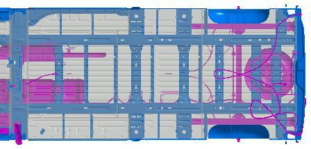
102 21 CROSS SECTION OF REAR AXLE The cross section is given with an asymmetrical travel, with first fit tyres and bump stops pressed down as far as possible. A clearance of 10 mm must be added in relation to the tyre for any bodywork positioning. Additional clearance may be needed for fitting snow chains. Note: Refer to the bodyshop technicians' drawings for chassis cabs. The wheelbase of a vehicle with an increasing load varies with the kinematics of the rear axle. To optimise the wheel arch of open transport vans, 5 mm should be added behind and 3 mm in front of the rear wheels, in unladen position. FRONT +10 mm REAR mm mm REAR AXLE of PLATFORM CAB and PANEL VAN, [ FWD ] up-to-date data on body guidelines (online body guidelines). Data status August
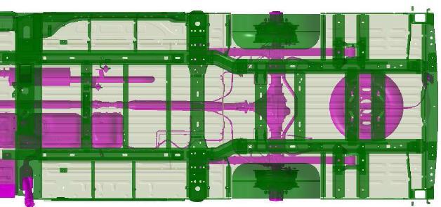
![21 CROSS SECTION OF REAR AXLE REAR AXLE of PANEL VAN [ RWD, twin wheels ] 2151 1091 460 195 FRONT WHEEL DRIVE CHASSIS CAB OR CHASSIS DOUBLE CAB](/docs-images/73/69516495/images/103-2.jpg "REAR AXLE of CHASSIS CAB and CREW CAB [ FWD, single wheels ] up-to-date data on body guidelines (online body guidelines).")
103 21 CROSS SECTION OF REAR AXLE REAR AXLE of PANEL VAN [ RWD, twin wheels ] FRONT WHEEL DRIVE CHASSIS CAB OR CHASSIS DOUBLE CAB REAR AXLE of CHASSIS CAB and CREW CAB [ FWD, single wheels ] up-to-date data on body guidelines (online body guidelines). Data status August


![] up-to-date data on body](/docs-images/73/69516495/images/104-3.jpg "guidelines (online body")

104 21 CROSS SECTION OF REAR AXLE REAR AXLE of CHASSIS CAB and CREW CAB [ RWD, single wheel ] REAR AXLE of CHASSIS CAB and CREW CAB [ RWD, twin wheel ] up-to-date data on body guidelines (online body guidelines). Data status August
105 22 WHEELBASE EXTENSION FOR CHASSIS CAB AND PLATFORM CAB (FWD) Alteration of the wheelbase is not generally recommended. The Movano range with 3 wheelbase options caters for most application purposes. However, if it is necessary to alter the wheelbase, ensure that the following recommendations are complied with: Modification of the wheelbase with front wheel drive will alter the distribution of load on the vehicle axles. For any wheelbase lengthening operation, this variation must be taken into account and it must be ensured that the maximum permissible load values per axle are respected.. (Also see chapter 79: Maximum authorised load per axle) Impacts related to the changes on the basic vehicle are the responsibility of the converter. The following instructions must be followed with regard to the braking control system: No changes to the hoses No change to the handbrake cables, but lengthened control rod. Compliance with the handbrake adjustment procedure. Important: OPEL/ VAUXHALL do not allow any modification to the wheelbase on rear wheel drive vehicles. OPEL/ VAUXHALL do not allow any modification to the wheelbase on vehicles with ESP. For front-wheel drive vehicles with a 4332mm wheelbase, lengthening by 10% is possible, except on the version with ESP. For safty reasons it is not allowed to shorten or extend the ABS cable. The permissible axle loads, gross vehicle weights and centre of gravity locations must be complied with. Further information regarding permissible weights is contained on the vehicle type identification plates on the vehicle itself. The minimum front axle load must be complied with in all load states. On no account should modifications be made to the vehicle width, vehicle height or vehicle length if they exceed the threshold values specified in the current version of the Conversion Guideline (also see chapter 7). up-to-date data on body guidelines (online body guidelines). Data status September
106 22 WHEELBASE EXTENSION FOR CHASSIS CAB AND PLATFORM CAB (FWD) 1. CHASSIS SINGLE CAB and CREW CAB without ESP The recommended splice line has been determined based on considerations of structural soundness (maintenance of the tank and exhaust interfaces) and the location of cross members and reinforcements. The splice line is located 2615 mm behind the front axle. The overlap between the longitudinal beam and reinforcement must be at least 300 mm on each side. CHASSIS SINGLE CAB and CREW CAB rear axle 2615 mm X front axle rear axle X = Wheelbase extension up-to-date data on body guidelines (online body guidelines). Data status September
107 22 WHEELBASE EXTENSION FOR CHASSIS CAB AND PLATFORM CAB (FWD) 2. PLATFORM CAB without ESP The recommended splice line has been determined based on considerations of structural soundness (maintenance of the tank and exhaust interfaces) and the location of cross members and reinforcements. The splice line is located 2460 mm behind the front axle. For a large extension to the wheelbase (10% max.), depending on the floor panel used, one or two under floor reinforcement cross members may be added between the main side members The overlap between the longitudinal beam and reinforcement must be at least 200 mm on each side. PLATFORM CAB rear axle 2460 mm X front axle rear axle X = Wheelbase extension 3. MAXIMUM POSSIBLE EXTENSION This converted vehicle (Modification of the wheelbase / rear overhang) shall not exceed the maximum vehicle length. See Chapter 7 MAIN VIEWS AND DIMENSIONS ". up-to-date data on body guidelines (online body guidelines). Data status September
108 23 MODIFYING THE REAR OVERHANG Modification of the rear overhang will alter the distribution of load on the vehicle axles. Make sure that you do not exceed the permissible axle loads. Doing so would prevent the ESP system from functioning correctly on vehicles which are equipped with this feature. Further information regarding permissible weights is contained on the vehicle type identification plates on the vehicle itself. (Also see chapter 79 "Maximum load per axle") The extension to the rear overhang must not exceed the maximum authorized body limit. The dimensions of the basic vehicle are available in chapter 7. An extended overhang prevents: - The installation of a lift tailgate - The installation of a platform on this overhang - The assembly of a classic coupling device. If installing a new trailer coupling device, ensure validation in accordance with the regulatory requirements. Conversions (extension or shortening of the overhang) must not disrupt the correct operation of the ESP (load distribution variation). Important: The permissible axle loads, gross vehicle weights and centre of gravity locations must be complied with. Further information regarding permissible weights is contained on the vehicle type identification plates on the vehicle itself. On no account should modifications be made to the vehicle width, vehicle height or vehicle length if they exceed the threshold values specified in the current version of the body / equipment When installing a new coupling, plan for a validation, in compliance with regulatory requirements It is prohibited to cut the rear attachment of the leaf spring and the rear end cross member. up-to-date data on body guidelines (online body guidelines). Data status September
109 23 MODIFYING THE REAR OVERHANG 1. CHASSIS SINGLE CAB AND CREW CAB 1.1. Extension of the rear overhang The recommended extension area (4) is determined according to structural constraints (Rear leaf spring attachment, etc.) and the existence of cross members or reinforcements. The extension area is located between the rear suspension attachments (3) and the rear end cross member (5). For Rear-wheel-drive versions, the maximum authorised overhang for the loading compartment (D2) is more restrictive than the maximum-extension overhang (D1); see table in Section 6. The space between the end of the loading compartment and the maximum extension may only be employed to install components solely used statically; example: tailgate. The reinforcements in the side members (point 6) must be kept. If a modification is made, these side members must be reinforced by equivalent parts. An extension of more than 385 mm requires one or more cross members to be added. The rear tow eye function must be kept. REAR CHASSIS: AERIAL VIEW (WITH CLOSURE ELEMENTS REMOVED) : Rear axle front attachment 2: Rear axle + wheel 3: Rear axle rear attachment 4: Cutting area 5: Rear end cross member 6: Side member internal reinforcement 5 6 It is essential that the extension to the overhang keep or add additional reinforcements to each side member (see 6, view above), located in line with the rear leaf spring attachments (see 3, view above). up-to-date data on body guidelines (online body guidelines). Data status September
110 23 MODIFYING THE REAR OVERHANG CHASSIS SINGLE CAB and CREW CAB front axle rear axle 1 F Z4 D1 D2 D 2 1 = Crew Cab 2 = Extension of rear overhang D = Standard rear overhang D1 = Maximum rear overhang D2 = Loading compartment rear overhang Z4 = Distance between the centre of gravity of the loading and the rear axle The dimensions ( D; D1; D2; Z4) of the vehicle see Chapter 7. up-to-date data on body guidelines (online body guidelines). Data status September
111 23 MODIFYING THE REAR OVERHANG 1.2. Shortening of the rear overhang The shortening of the rear overhang shall apply to the versions with rear-wheel drive for the chassis with single cab and crew cab. The shortening area is located between the rear bracket of the rear suspension (3) and the rear cross member (5). See first picture REAR CHASSIS: AERIAL VIEW in this chapter 23. If a towbar is installed, reinforcements should be planned accordingly. CHASSIS SINGLE CAB and CREW CAB (with RWD) front axle rear axle 1 F Z4 D 2 1 = Crew Cab 2 = Shortened rear overhang D = Standard rear overhang Z4 = Distance between the centre of gravity of the loading and the rear axle The dimensions (D; Z4) of the vehicle, see Chapter 7. up-to-date data on body guidelines (online body guidelines). Data status September
112 23 MODIFYING THE REAR OVERHANG 2. PLATFORM CAB It is prohibited to cut the rear attachment of the leaf spring and the rear end cross-member in the platform cab version. In the case of the fitting of a towbar it is the responsibility of the converter to observe the regulations. Depending on the overhang extension, one or more under-floor reinforcing cross members may be added between the main side members. front axle rear axle F Z4 D1 D 2 2 = Extension of rear overhang D = Standard rear overhang D1 = Maximum rear overhang Z4 = Distance between the centre of gravity of the loading and the rear axle The dimensions (D; D1; Z4) of the vehicle, see Chapter MAXIMUM EXTENSION The maximum extension (2) is limited by the maximum vehicle length. See Chapter 7 - MAIN VIEWS AND DIMENSIONS ". up-to-date data on body guidelines (online body guidelines). Data status September
113 Conversion Guideline Opel Movano [ X62 ] Part 2 - Chapter Edition: August 2013 GME Engineering Special Vehicle Development / Light Commercial Vehicles Rüsselsheim / Germany
114 CONTENTS Conversion Guideline- Part 2 CHAPTER DESCRIPTION PAGE 24 BULKHEAD FEED-THROUGH 3 25 CAB FLOOR DRILLING AREA 5 26 DRILLING AREA ON REAR FLOOR OF PANEL VAN 6 27 CAB ROOF FOR CAMPERVAN MIRRORS AIR EXTRACTION TYRES AND TURNING CIRCLE SPARE WHEEL AIRBAG DEPLOYMENT VOLUME SEATS SEAT BELTS LAMP INSTALLATION EUROPEAN REGULATIONS HEIGHT OF CAB ROOF GROUND CLEARANCE CONVERSION LIMITS WITH ESP INSTALLATION AND ATTACHMENT OF EQUIPMENT ON DASHBOARD * VEHICLE SPEED RESTRICTION TABLE OF EQUIPMENT WEIGHTS ADDITIONAL WEIGHT ON DOORS ASSEMBLING A SECOND HEATER UNIT INSTALLING ADDITIONAL AIR-CONDITIONING * INSTALLING AN ADDITIONAL BOILER 60 * = This chapter is new or was modified after the last edition of November up-to-date data on body guidelines (online body guidelines).
. 1.")
.")
115 24 BULKHEAD FEED-THROUGH Opel recommends using the existing grommet. However, if the coachbuilder faces major constraints, another hole may be used (see paragraph 2). 1. Using the existing grommet So as to not adversely affect certain performance levels, only the grommet for the main wiring harness behind the engine interconnection unit may be used. The plastic clamp on the passenger compartment side must be changed (for identical reassembly). Sealing must not be adversely affected. LOCATION OF THE HARNESS GROMMET up-to-date data on body guidelines (online body guidelines). Data status September


 Areas with constraints N.")


116 24 BULKHEAD FEED-THROUGH 2. Using another hole The area in which the hole is made must be chosen in accordance with technical constraints, particularly: - Proximity to neighbouring parts (depending on the version) - Travel/clearances (pedals, engine, etc.) - Proximity to heat sources (exhaust, etc.). In any case, no holes may be made in the bulkhead: - In weld areas - In mating areas - In the areas with structural constraints specified below: LOCATION OF AREAS WITH CONSTRAINTS ON THE BULKHEAD (INSIDE THE PASSENGER COMPARTMENT) Areas with constraints N.B: Holes adversely affect the following performance levels: - Acoustics - Sealing - Perception of external odours Perform burring and corrosion prevention treatment (see technical data sheet: Specific guidelines on corrosion) on each edge of the hole created in the bulkhead. Excluding round holes, all cut-out shapes must have a cut-out radius. Check that the sealing of the bulkhead feed-through is effective. up-to-date data on body guidelines (online body guidelines). Data status September

117 25 CAB FLOOR DRILLING AREA Points between the driver s seat and the cab partition in right- and left-hand drive vehicles have been identified as drilling areas. Before any drilling is performed, take note of the various elements such as wiring, brake pipes, hand brake cables, the fuel tank, etc. The maximum dimension of the hole to be drilled is 30mm. After drilling, the filings or shavings must be vacuumed and a corrosion inhibitor used; please refer to the Specific Corrosion Guidelines. Use a grommet for protection and a silicon seal for water tightness. LOCATION OF CAB FLOOR DRILLING AREAS 1: Limit between the cab floor and the loading bed 1 up-to-date data on body guidelines (online body guidelines). Data status June

, take note of the various")


.")
118 26 DRILLING AREA ON REAR FLOOR OF PANEL VAN Before any drilling is performed (e.g. for fitting a wooden floor), take note of the various elements such as wiring, brake pipes, hand brake cables, the fuel tank, etc. After drilling, the filings or shavings must be vacuumed and a corrosion inhibitor used; please refer to the Specific Corrosion Guidelines. Use a grommet for protection and a silicon seal for water tightness. The different views below show the position of the elements below the floor (fuel tank, exhaust line, muffler and screen, etc). Drilling areas have been identified along with a fastening diagram in case of a location to the right of the under-floor cross member. LOCATION OF LOADING BED DRILLING AREAS (Front wheel drive panel van L1) up-to-date data on body guidelines (online body guidelines). Data status June


")


119 26 DRILLING AREA ON REAR FLOOR OF PANEL VAN LOCATION OF LOADING BED DRILLING AREAS (Front wheel drive panel van L2) LOCATION OF LOADING BED DRILLING AREAS (Front wheel drive panel van L3) up-to-date data on body guidelines (online body guidelines). Data status June


120 26 DRILLING AREA ON REAR FLOOR OF PANEL VAN LOCATION OF LOADING BED DRILLING AREAS (Single wheel rear drive panel van L3) LOCATION OF LOADING BED DRILLING AREAS (Twin wheel rear drive panel van L3) up-to-date data on body guidelines (online body guidelines). Data status June


 CROSS")


121 26 DRILLING AREA ON REAR FLOOR OF PANEL VAN LOCATION OF LOADING BED DRILLING AREAS (Twin wheel rear drive panel van L4) CROSS MEMBER FASTENING DIAGRAM 1: Loading bed 2: Floor reinforcement cross member 3: Reinforcement flange up-to-date data on body guidelines (online body guidelines). Data status June


122 27 CAB ROOF FOR CAMPERVAN Platform cabs and chassis cabs specific to campervans have a specific rear aspect and roof. Due to the presence of additional structural reinforcement, these versions meet regulatory requirements on seatbelt anchor points (ECE14). 1. Campervan versions PLATFORM CAB 505 +/ 1.5 N.B.: The rear section of the upper cantrail can be cut down by 156 mm on platform cab versions CHASSIS CAB 523 +/ up-to-date data on body guidelines (online body guidelines). Data status September
 for basic")
 for vehicles fitted")
 for basic")

123 27 CAB ROOF FOR CAMPERVAN 2. Platform Cab versions H2 It is possible to remove the cross member (1) for basic vehicles fitted with: - 2 individual seats - 2 suspended seats - 2 individual campervan seats It is forbidden to remove the cross member (1) for vehicles fitted with a 2-seater bench 1 3. Panel Van versions H2 It is possible to remove the cross member (1) for basic vehicles, without partition, fitted with: - 2 individual seats - 2 suspended seats - 2 individual campervan seats It is forbidden to remove the cross member (1) for vehicles fitted with a 2-seater bench up-to-date data on body guidelines (online body guidelines). Data status September


124 28 MIRRORS Chassis cabs and platform cabs come with door mirrors as standard, they apply up to a vehicle width of 2170 mm. Long arm door mirrors can be ordered on option, they apply up to a vehicle width of 2,170 to 2,350 mm. The mirrors have a built-in side indicator. There are two types of indicator: 5 W or 16 W, depending on the length of the vehicle. The overall width of the vehicle with the standard mirrors is 2,470 mm and 2,654 mm with the long arm mirrors. Important: To change the indicator power supply, see chapter 125. For maximum body dimensions, see Chapter 7. STANDARD DOOR MIRRORS (Overall width from 2,020 to 2,170 mm) Type Side Steering Reference Manual without defrosting Right Left Steering right R (5 W) / R (16 W) Steering left R (5 W) / R (16 W) Steering right R (5 W) / R (16 W) Steering left R (5 W) / R (16 W) Manual with defrosting Right (S) Left Steering right R (5 W) (S) / R (16 W) (S) Steering left R (5 W) (S) / R (16 W) (S) Steering right R (5 W) / R (16 W) Steering left R (5 W) / R (16 W) (S): with temperature sensor up-to-date data on body guidelines (online body guidelines). Data status September
 Left Steering left 963010148R (16W) (S) 963020135R (16W) Electric")
.")
125 28 MIRRORS LONG ARM DOOR MIRRORS (Overall width from 2,170 to 2,350 mm) Type Side Steering Reference Electric with defrosting Right (S) Left Steering left R (16W) (S) R (16W) Electric with defrosting Right (S) Left Steering right R (16W) (S) R (16W) (S): with temperature sensor up-to-date data on body guidelines (online body guidelines). Data status September
 to achieve satisfactory performance when closing doors (front, side, rear), activating the heating and ventilation systems and in airbag deployment.")
126 29 AIR EXTRACTION Air must be extracted from the interior (cab, loading area, etc.) to achieve satisfactory performance when closing doors (front, side, rear), activating the heating and ventilation systems and in airbag deployment. After any modification to the extraction system, the air extraction surface area must be equivalent to the original system. The modified system must not let water, outside air, dust or mud in. It must also reduce noise levels. It must not compromise the integrity of the vehicle (where necessary, fit vent glass to prevent access to the door opening controls, etc.). It must be protected from potential impacts (stones thrown up from the road, etc.). In the chassis cab and the chassis double cab, the air outlets are located on either side of the cab back panel. The surface area of each air outlet is 10,070 mm². In the panel van, the air outlets are located on either side of the rear bumper. The surface area of each air outlet is 10,679 mm². CHASSIS CAB up-to-date data on body guidelines (online body guidelines). Data status June
.")
127 29 AIR EXTRACTION CHASSIS DOUBLE CAB up-to-date data on body guidelines (online body guidelines). Data status June

.")
128 29 AIR EXTRACTION PANEL VAN air outlets up-to-date data on body guidelines (online body guidelines). Data status June
129 30 TYRES AND TURNING CIRCLE TYRES The basic tire assembly, except in specific situations, is as follows: Version Drive GVW [ kg ] Rear wheels Tyre size Rim size PANEL VAN FWD 2800 Single 215/65 R 16 C 109/107R 6 1/2Jx16/ET66 PANEL VAN FWD 3300 Single 215/65 R 16 C 109/107R 6 1/2Jx16/ET66 PANEL VAN + CHASSIS CAB + CREW CAB + PLATFORM CAB PANEL VAN + CHASSIS CAB + CREW CAB PANEL VAN + CHASSIS CAB + CREW CAB PANEL VAN + CHASSIS CAB + CREW CAB FWD 3500 Single 225/65 R16C (112/110)R 6 1/2Jx16/ET66 RWD 3500 Single 235/65 R16C (115/113)R 7Jx16/ET66 RWD 3500 Twin 195/75 R16C (107/105)T 5 1/2Jx16/ET117 RWD 4500 Twin 195/75 R16C (107/105)T 5 1/2Jx16/ET117 TURNING CIRCLE Kerb-to-kerb and wall-to-wall turning circle diameters are given for the different wheelbases. Front wheel drive Rear wheel drive L1 L2 L3 L3 L4 Wheelbase (mm) Kerb-to-kerb turning circle diameter (m) 12 13,6 15,65 13,6 15,65 Wall-to-wall turning circle diameter (m) 12,5 14,1 16,15 14,1 16,15 up-to-date data on body guidelines (online body guidelines). Data status September
 Wall-to-wall Kerb-to-kerb up-to-date data on body guidelines (online body guidelines).")
130 30 TYRES AND TURNING CIRCLE TURNING CIRCLE DIAMETERS IN RELATION TO WHEELBASE 18,00 Turning circle (m) 16,00 14,1 16,15 15,65 14,00 12,5 13,6 12, , Wheelbase (mm) Wall-to-wall Kerb-to-kerb up-to-date data on body guidelines (online body guidelines). Data status September

131 31 SPARE WHEEL The spare wheel is held under the vehicle frame using a winch and secured by tightening a cable using the wheel wrench and adapter. Some vehicles are equipped with a tyre repair kit instead of a spare wheel. If the overhang is extended or modified the spare wheel remains in its place. 1. Position of spare wheel in panel van and platform chassis with front wheel drive. POSITION OF SPARE WHEEL 1= front axle, 2 = centre axle Distance between front axle and spare wheel axle by wheelbase: L1 = 3613 mm L2 = 4113 mm L3 = 4763 mm up-to-date data on body guidelines (online body guidelines). Data status August


132 31 SPARE WHEEL 2. Position of spare wheel in chassis cab with front wheel drive. POSITION OF SPARE WHEEL 1= front axle, 2 = centre axle Distance between front axle and spare wheel axle by wheelbase: L2 = 4300 mm L3 = 4950mm 3. Assembly spare wheel with winch up-to-date data on body guidelines (online body guidelines). Data status August


133 31 SPARE WHEEL Spare wheel at single wheel vehicles (without mounting plate) Spare wheel at twin wheel vehicles (with mounting plate) Twin wheel vehicles have an additional mounting plate attached to the spare wheel. Before using the wheel, undo the nut and remove the mounting plate. When reinstalling a spare wheel, attach the mounting plate and secure with the nut. When installing a spare wheel, route the cable from the back and through the centre of the wheel. Attach the retainer and pin, ensuring it is correctly positioned and that the front of the wheel will be facing downwards. Tighten cable using the wheel wrench and adapter until the wheel is secured. Warning: We remind you that the usage of pneumatic and electric tools provokes the destruction of the winch. This winch must be manually used. up-to-date data on body guidelines (online body guidelines). Data status August

134 32 AIRBAG The airbag system consists of a number of individual systems depending on the scope of equipment. Depending on model and country the vehicle is equipped with various airbags. The passenger airbag is supplied as an option and it may be deactivated. For more information, also see chapter 137, 141 and general conversion recommendations. Note: Warning: The front passenger airbag can be deactivated. Consult the repair manual to configure the ECU in accordance with the equipment fitted. Do not make any modifications to the airbag system as this will invalidate the vehicle type approval. If handled improperly the airbag systems can be triggered in an explosive manner. Keep the area in which the airbag inflates clear of obstructions. Do not stick anything on the airbag covers and do not cover them with other materials, also see chapter 41. On no account may any modifications be made to the airbag system or the belt tensioner system. Modifications to or work incorrectly carried out on a restraint system (seat belt and seat belt anchorages, belt tensioner or airbag) or its wiring, can cause the restraint systems to stop functioning correctly, e.g. the airbags or belt tensioners could be triggered inadvertently or could fail in accidents. Vehicle parts that create vibrations must not be secured in the proximity of the airbag control unit or sensor installation locations, nor may modifications be made to the floor structure in the proximity of the airbag control unit or the satellite sensors. Reliable operation of the front airbag, side airbag and belt tensioners is otherwise no longer guaranteed. FRONT AIRBAGS 500 mm 950 mm up-to-date data on body guidelines (online body guidelines). Data status June
.")
135 32 AIRBAG deployment area of the driver airbag 300 mm 550 mm Important: The steering wheel is reach-adjustable. The adjustment of the steering wheel must be taken into account. up-to-date data on body guidelines (online body guidelines). Data status June
.")
136 32 AIRBAG deployment area of the passenger airbag 350 mm 550 mm 150 mm up-to-date data on body guidelines (online body guidelines). Data status June
 5: Airbag deactivation")
137 32 AIRBAG Location of airbag control unit Comment: The ECU is in the same position for both left- and right-hand drive vehicles. Location of airbag and restraint systems components in the vehicle : Driver airbag 2: Passenger airbag 3: Side airbags 4: Warning light (in instrument cluster) 5: Airbag deactivation light (on roof console) 6: Airbag control unit (ECU) Note: For more information, also see chapter 141. up-to-date data on body guidelines (online body guidelines). Data status June
138 33 SEATS The front seats vary depending on the equipment level, the options and the country of sale. The driver s seat is tilt and height-adjustable and has longitudinal adjustment. As an option, it may have an armrest, heating, lumbar adjustment, a side airbag, etc. A sprung driver s seat is available as an option. The specific campervan versions are fitted with a swivelling driver s seat. Passengers can have a single seat similar to the driver s seat or a 2-seater bench seat. The 2-seater bench seat can have a swivelling table, a storage compartment, etc. The chassis double cab versions are fitted with a rear 4-seater bench seat. Location of R points ( ) X Y Z Single seat 20 1,133 ± Centre bench seat 19 or ,153 ± Side bench seat 19 1,153 ± For the single seat, the R point is given for a position -30 mm from the fully back position (total longitudinal travel of 210 mm) and at mid-height (total vertical travel of 60 mm). On conversion, it may be necessary to remove the seats. Seat anchorages are component elements for vehicle type approval and must not therefore be modified. In particular, it is forbidden to: - modify the original anchorage point positions, - insert other elements into the original assembly. Any modification will require a new type approval. On reassembly, tightening torques must be respected (use of a calibrated torque wrench is recommended). - Attachment of the seat or the 2-seater bench seat to the floor using M10x bolts, tightened to a torque of 44 Nm ± 15%. - Attachment of the chassis double cab 4-seater bench seat to the floor using M12x bolts, tightened to a torque of 62 Nm ± 15%. - Attachment of seat runners to the driver s seat podium using M8x bolts, tightened to a torque of 19.5 Nm ± 10%. up-to-date data on body guidelines (online body guidelines). Data status January
139 33 SEATS N.B.: Disassembly and reassembly must be carried out with the battery disconnected. For seats with the optional side airbag, direct contact between the connectors and the conductive parts must be avoided due to static electricity. Before carrying out any work on the airbags, the airbag ECU must be locked using the Clip diagnostic tool to disable the trigger lines (the airbag dashboard light is on continuously when contact is made). For regulatory reasons, it is not possible to replace a passenger seat with a two-seater bench or vice versa, without re-applying for approval of the new arrangement. On reassembly, tightening torques must be respected (use of a calibrated torque wrench is recommended). up-to-date data on body guidelines (online body guidelines). Data status January
140 34 SEAT BELTS Seat belts and their anchorages are component elements for vehicle type approval and must not therefore be modified. In particular, it is forbidden to: - modify the original anchorage point positions, - change the original fastening support, - insert other elements into the original assembly. - To remove the belt tensioner on a seat Attention No changes to the seat belt are permitted, otherwise the type approval expires. Any modification will require a new type approval. On conversion, it may be necessary to remove the seat belts. On reassembly, tightening torques must be respected (use of a calibrated torque wrench is recommended) and the following should be checked: - the correct positioning of the reel indexing before bolting, - that the strap is not twisted between the reel and the final anchoring point, - that no foreign body can come into contact with the strap, - that the strap is not altered by the vehicle conversion. If a floor or floor covering is added, it is essential to make a large enough cut-out so it does not interfere with the seat belt assembly. Fastening Tightening torque Comments Reel M10x bolt 21 Nm ± 15% - Same for rows 1 and 2 - Use of a new bolt on reassembly Fitting M10x bolt 21 Nm ± 15% - Same for rows 1 and 2 - Use of a new bolt on reassembly Angular member M9 nut for row 1 M10 bolt for row 2 21 Nm ± 15% - Special nut and bolt installed with belt Front stalk Special bolt 27 Nm ± 15% Rear stalk M12x bolt 62 Nm ± 15% - Attached to front seat and bench seat - Attached to floor - Use of a new bolt on reassembly up-to-date data on body guidelines (online body guidelines). Data status August


141 36 LAMP INSTALLATION EUROPEAN REGULATIONS FRONT ZONE ALL TYPES A2 - B2 D2 F2 Overall body width (without rearview mirrors) E2 C2 E E1 C D - F A - B D1 F1 C1 A1 - B1 A B C D E F A: Indicator B: Position C: Main Beam FRONT LAMPS D: Dipped Beam E: Fog lamp F: Fixed Bending Lamp* A A1 A2 B B1 B2 C C1 C2 D D1 D2 E E1 E2 F F1 F ** ** ** N.B: * = optional; ** = no value imposed *** = 800 für M1 und N1 **/* ** up-to-date data on body guidelines (online body guidelines). Data status August

. Data status August 2012 2 30")
142 36 LAMP INSTALLATION EUROPEAN REGULATIONS PANEL VAN REAR ZONE ALL TYPES Overall body width (without rearview mirrors) G2 - H2 - K2 N2 L2- M2 N N1 M1 K G-H L M L1 G1 H1 K1 G H K L M N REAR LAMPS G : Brake H: Position K : Indicator L: Reverse M : Fog N: Reflector G G1 G2 H H1 H2 K K1 K2 L L1 L2 M M1 M2 N N1 N ** ** N.B: ** = no value imposed up-to-date data on body guidelines (online body guidelines). Data status August
 P2 P3")


143 36 LAMP INSTALLATION EUROPEAN REGULATIONS SIDE ZONE ALL TYPES Overall body width (without rearview mirrors) P2 P3 P1 P Indicator in side mirror SIDE INDICATORS P P1 P2 P * Max N.B: * =350 für M1 und N1 For more information, also see chapter 125 up-to-date data on body guidelines (online body guidelines). Data status August
144 36 LAMP INSTALLATION EUROPEAN REGULATIONS DETAILS OF CHASSIS VERSION ALL TYPES Overall body width (without rearview mirrors) G2 - H2 K2 M2 L2 N2 G H K L M - N G1 - H1 K1 L1 M1 N1 K G H N M L REAR LAMPS Of CHASSIS VERSION G : Brake H : Position K : Indicator L : Reverse M : Fog N : Reflector G G1 G2 H H1 H2 K K1 K2 L L1 L2 M M1 M2 N N1 N ** ** N.B: ** = no value imposed up-to-date data on body guidelines (online body guidelines). Data status August
145 36 LAMP INSTALLATION EUROPEAN REGULATIONS ADDITIONAL INFORMATION If the vehicle overall width > 2100mm Mandatory use of gauge lights (2 front, 2 rear). If the vehicle overall length < 6000mm Side position indicator: fitted on the rearview mirror, with the type-approved choice of arm length according to the width of the body. The indicator is category 5, 5W bulb (type WY5W). If the vehicle overall length > 6000mm Provide the option for the indicator. The latter must be category 6, 16W bulb (type W16W). Side position indicator: fitted on the rearview mirror, with the type-approved choice of arm length according to the width of the body. Side position lamps and side reflectors are mandatory. Two reverse lamps. N.B.: There is the option UZB, for vehicles above a length of 6000 mm. This includes preparation for side flashing lights (Type W16W). See also Chapter 125. Attention: National regulations apply to all lamp and turn signal units. up-to-date data on body guidelines (online body guidelines). Data status August

146 37 HEIGHT OF CAB ROOF PLATFORM CAB : Cab roof 2: Loading bed 3: Roof Version H1: 1,747.5 mm ; Roof Version H2: 1,941.7 mm CHASSIS CAB, FRONT OR REAR WHEEL DRIVE : Cab roof 2: Rear side member 3: Version H1: 1,569 mm up-to-date data on body guidelines (online body guidelines). Data status June
147 39 GROUND CLEARANCE The ground clearance is given for a vehicle with a Gross vehicle weight (GVW). 1. Panel van Panel van L1, front wheel drive Panel van L2, front wheel drive Panel van L3, front wheel drive Panel van L3, Single wheel rear drive Panel van L3, twin wheel rear drive Panel van L4, twin wheel rear drive Height GVW (kg) Min. ground clearance (mm) 2, H1 3, , , H2 3, , H2 3, , H3 3, , H ,500 H3 169 H2 H3 3, H2 H3 4, H2 H3 4, Platform cab Platform cab L1 Platform cab L2 Platform cab L3 Height H1 H1 H2 H1 H2 GVW (kg) Min. ground clearance (mm) 3, up-to-date data on body guidelines (online body guidelines). Data status June
148 39 GROUND CLEARANCE 3. Chassis cab Height GVW (kg) Min. ground clearance (mm) Chassis cab L2, front wheel drive Chassis cab L2, front wheel drive Chassis cab L2 single wheel rear drive Chassis cab L3 single wheel rear drive H1 3, Chassis cab L3 twin wheel rear drive Chassis cab L4 twin wheel rear drive 4, Chassis double cab Height GVW (kg) Min. ground clearance (mm) Chassis double cab L2, front wheel drive Chassis double cab L2, front wheel drive Chassis double cab L2 single wheel rear drive Chassis double cab L3 single wheel rear drive H1 3, Chassis double cab L3 twin wheel rear drive Chassis double cab L4 twin wheel rear drive 4, up-to-date data on body guidelines (online body guidelines). Data status June
149 40 CONVERSION LIMITS WITH ESP ESP is a dynamic vehicle control system which controls both dynamic directional and transverse forces acting on the vehicle. Modifications to vehicles with ESP may cause this system to stop functioning correctly and may lead to system shutdowns and incorrect control interventions. Conversions must not disrupt the operation of the ESP. COMPLIANCE WITH THE CENTRE OF GRAVITY See chapter 1 Calculating the centre of gravity YES Inside V red frame NO Outside V red frame If modification of: Structure Frame Powertrain Retarder ESP sensors Roof racks See table in chapter 2. Recommendation: Order a vehicle without ESP In all cases, the coach-builder, who is solely liable, will ensure the level of ESP functioning and vehicle handling. Refer to the general recommendations. up-to-date data on body guidelines (online body guidelines). Data status August
 with technical maximum")
150 40 CONVERSION LIMITS WITH ESP 1. CENTRE OF GRAVITY POSITION OF THE CONVERTED VEHICLE The centre of gravity of the converted vehicle must be calculated when the vehicle is: - Laden = GVW (Gross Vehicle Weight) with technical maximum permitted on one axle To ensure that the ESP functions properly, the centre of gravity position of the converted vehicle, when laden, must remain within the limits of the red frame V. The tolerance for X and Y is ± 8% Only the Z position of the centre of gravity when laden (GVW) should be taken into consideration. Please refer to the following tables for the limits "V" of each vehicle type. FRONT WHEEL DRIVE Wheelbase X mini/maxi (mm) Y (mm) Z maxi (mm) / Panel Van and Platform Cab, GVW = 3,5t, / camper van 1100 or 1150 (wider axle) 1945/2330 Y ± / Opel air suspension ditto 1000 Bus GVW = 3,9t 4332 ditto 1050 up-to-date data on body guidelines (online body guidelines). Data status August
151 40 CONVERSION LIMITS WITH ESP REAR WHEEL DRIVE Wheelbase X mini/maxi (mm) Y (mm) Z maxi (mm) Panel van GVW = 3,5t, single wheels Panel van GVW = 4,5t twin wheels / Y ± / / FRONT WHEEL DRIVE Wheelbase X mini/maxi (mm) Y (mm) Z maxi (mm) Chassis Cab and Double Cab GVW = 3,5t */ camper van or 1150 (wider axle) 1945/2330 Y ± / Opel air suspension ditto 1000 REAR WHEEL DRIVE Chassis Cab and Double Cab GVW = 3,5t single wheels Chassis Cab and Double Cab GVW = 4,5t twin wheels Wheelbase X mini/maxi (mm) Y (mm) Z maxi (mm) / / Y ± / / Note: - For the calculation of the centre of gravity and its position on the basic vehicle, see chapter The X dimensions are given in relation to the centre of the FRONT wheel - The Y dimensions are given in relation to the centreline of the vehicle - The Z dimensions are measured up-to-date data on body guidelines (online body guidelines). Data status August
152 40 CONVERSION LIMITS WITH ESP 2. MODIFICATIONS AFFECTING THE OPERATION OF THE ESP The table below details the modifications of parts or functions: * : the operation of ESP is greatly affected by this type of transformation ** : the operation of ESP is likely to be affected if the corresponding comments are not complied with. Modification Detail s * ** Comments Structure Chassis Wheelbase Body stiffness Tracks Suspension (springs, travel limits, anti-roll bars, shock absorbers) Tyres (dimensions, stiffness, etc.) Ratio of the steering wheel and wheels Braking system Power train Engine, gearbox X X X X X X X X Maximum 30% reduction in body torsional stiffness along the X axis (measured between the two axles) pre- and post-conversion. Anything that changes the stiffness and/or elastokinematics of the suspension. Only tyres with characteristics identical to standard tyres (dimensions, load index, speed code) Only if different from standard tyres Only one modification of the rigid pipe routing is permitted. Electromagnetic retarder X The sensors connected to the ESP (steering wheel angle, wheel speed, lateral acceleration, yaw angle) Displacement and modification of the installation X CAN - Bus X Roof rack Trailer (semi-trailer) Modifications to the sensors (steering angle sensor, yaw rate sensor, wheel rotational speed sensor). Modifications to the permissible gross vehicle weight. X X X X Comply with the permitted load on the standard version. up-to-date data on body guidelines (online body guidelines). Data status August
153 40 CONVERSION LIMITS WITH ESP 3. Terms of use of Options ESP 3.1. The compliance with the conditions in Section 1 ("center of gravity position") If the conversion does not affect the function of the ESP (see section 2 "changes affecting the ESP operation"), then the vehicle can be selected with standard ESP, and no further testing The non-compliance with the conditions in Section 1 ("center of gravity position") If an attachment, the body, mounted equipment or modifications cause an extreme displacement of the centre of gravity on a vehicle equipped with ESP, the converter contributes the sole responsibility and must ensuring that ESP works properly. Where required, the ESP should be deactivated or it is recommended to choose a vehicle without ESP. 4. Deactivating the option '' ESP'' If ESP has been deactivated, the driver will then have to adapt his / her style of driving accordingly. Otherwise the driver could lose control of the vehicle and cause an accident, especially when driving near the system's limits. For this reason, the converter will have to put a well visible warning sticker on the dashboard that the ESP has been disabled. The converter must point to the changed handling characteristics of the vehicle. Proposed location of the warning sticker up-to-date data on body guidelines (online body guidelines). Data status August


154 41 INSTALLATION AND ATTACHMENT OF EQUIPMENT ON DASHBOARD Equipment can be installed on the dashboard in the zones indicated below. The vehicle interior must be designed in such a way that airbags can fully deploy without impediment. Please also see chapter 32 Airbag deployment volume. LOCATION OF INSTALLATION AND ATTACHMENT ZONES N.B.: Keep the area in which the airbag inflates clear of obstructions. Do not stick anything on the airbag covers and do not cover them with other materials. Depending on the version and options, the central area may be smaller due to a door or removable shelf being fitted. It is forbidden to make modifications to the cross girder of the dashboard, as this element is part of the vehicle structure. up-to-date data on body guidelines (online body guidelines). Data status September


155 41 INSTALLATION AND ATTACHMENT OF EQUIPMENT ON DASHBOARD 1. Lateral zones The drilling and attachment depth must not exceed 12 mm. SIZING Zone behind the mobile phone dock The drilling and attachment depth must not exceed 25 mm. SIZING : Prohibited zone 100 up-to-date data on body guidelines (online body guidelines). Data status September

156 41 INSTALLATION AND ATTACHMENT OF EQUIPMENT ON DASHBOARD 3. Central area The drilling and attachment depth must not exceed 25 mm. SIZING : Prohibited zone if folding shelf fitted N.B.: If a cover is fitted, the effective height is restricted to 40 mm. up-to-date data on body guidelines (online body guidelines). Data status September

157 42 VEHICLE SPEED RESTRICTION 1. Cruise control - speed limiter The cruise control - speed limiter is a driving aid and is available as an option depending on the equipment level. Cruise control is a function that maintains the vehicle at a constant speed selected by the driver. The speed limiter is a function that helps the driver to stay below a certain speed previously selected by the driver. The speed setting is left up to the driver whose responsibility it is to stay within speed limits and to remain vigilant. Before use and for any further information on how this function works, please refer to the vehicle s hand book. 2. Client speed restriction This option is more specifically aimed at customers, in particular fleets, who want the vehicle s speed to be limited without the driver being able to disable the restriction. The restriction value is chosen by the customer and is programmed into the engine ECU in the factory. The restriction value can be modified or removed using the TECH2 diagnostic tool. The restriction values are as follows: 90, 100, 110, 120 or 130 km/h. The user must be notified of the status and value of the vehicle s speed restriction. This information must be permanently displayed in the cockpit where it can be seen by the driver. A regulatory sticker corresponding to the selected restriction value must therefore be obtained from the Opel / Vauxhall dealer network. STICKER Part number km/h mph up-to-date data on body guidelines (online body guidelines). Data status August

158 42 VEHICLE SPEED RESTRICTION STICKER POSITION A sticker can be affixed to the rear of the vehicle to inform other road users. 3. Regulatory speed restriction Depending on the category of vehicle and the law in the country where the vehicle is sold, the vehicle s speed can be restricted during manufacture with no option to disable this restriction. The restriction value is programmed into the engine ECU in the factory. The restriction value cannot be modified or removed using the Clip diagnostic tool or by changing the engine ECU. The vehicle s maximum speed must be displayed on the rear of the vehicle. If a vehicle restricted during manufacture is exempt from restriction (for example emergency vehicle, police) or for restriction of a vehicle that was not originally restricted, major vehicle maintenance arranged by the Central Engineering Department can be carried out. Using the TIS an authorized Opel/Vauxhall dealers is able to create a VCI-request. up-to-date data on body guidelines (online body guidelines). Data status August
159 43 TABLE OF EQUIPMENT WEIGHTS Wheelbase PANEL VAN FRONT WHEEL DRIVE FRONT WHEEL DRIVE FRONT WHEEL DRIVE REAR WHEEL DRIVE REAR WHEEL DRIVE (twin wheels) REAR WHEEL DRIVE (twin wheels) E1 =3182 mm E2 =3682 mm E3 =4332 mm E2 =3682 mm E2 =3682 mm E3 =4332 mm Front Rear Total Front Rear Total Front Rear Total Front Rear Total Front Rear Total Front Rear Total Driver's seat - Arm rest 1,0 0,5 1,6 1,1 0,4 1,6 1,2 0,4 1,6 1,1 0,4 1,6 1,1 0,4 1,6 1,2 0,4 1,6 Seats - Fixed shelf bench seat on 1/2 bench seat back rest instead of fixed bench seat 0,7 0,5 1,2 0,8 0,4 1,2 0,8 0,4 1,2 0,8 0,4 1,2 0,8 0,4 1,2 0,8 0,4 1,2 Storage - Roof rack 1,4 0,5 1,9 1,5 0,4 1,9 1,6 0,4 1,9 1,5 0,4 1,9 1,5 0,4 1,9 1,6 0,4 1,9 Panel partition instead of no partition 13,2 11,7 24,9 14,8 10,1 24,9 16,3 8,6 24,9 14,8 10,1 24,9 16,3 11,2 27,5 18,0 9,5 27,5 Wheels - Bolt cover instead of wheel centre cover 0,4 0,4 0,7 0,4 0,4 0,7 0,4 0,4 0,7 0,4 0,4 0,7 Seats - Lumbar adjustment 0,1 0,1 0,2 0,1 0,0 0,2 0,1 0,0 0,2 0,1 0,0 0,2 0,1 0,0 0,2 0,1 0,0 0,2 Seats - Rotating shelf bench seat on 1/2 bench seat back rest, storage tray under bench seat and tilting seat cushion instead of fixed shelf bench seat on 1/2 5,4 3,0 8,4 5,8 2,6 8,4 6,2 2,2 8,4 5,8 2,6 8,4 5,8 2,6 8,4 6,2 2,2 8,4 bench seat back rest Wheels - Integral covers instead of bolt covers 0,7 0,7 1,5 0,7 0,7 1,5 0,7 0,7 1,5 0,7 0,7 1,5 Instrument panel: upper storage and 1 DIN collapsible shelf 1,2 0,8 2,0 1,3 0,7 2,0 1,4 0,6 2,0 1,3 0,7 2,0 1,3 0,7 2,0 1,4 0,6 2,0 Front side airbag (driver) 0,6 0,3 0,9 0,6 0,3 0,9 0,7 0,2 0,9 0,6 0,3 0,9 0,6 0,3 0,9 0,7 0,2 0,9 Front side airbag (passenger - not compatible with seat 0,6 0,3 0,9 0,6 0,3 0,9 0,7 0,2 0,9 0,6 0,3 0,9 0,6 0,3 0,9 0,7 0,2 0,9 bench) Passenger airbag 1,5 0,2 1,7 1,5 0,2 1,7 1,5 0,2 1,7 1,5 0,2 1,7 1,5 0,2 1,7 1,5 0,2 1,7 Trailer tow bar -6,4 31,4 25,0-5,5 30,6 25,0-4,7 29,7 25,0-10,3 36,5 26,1-10,3 36,5 26,1-4,6 30,7 26,1 Mud flaps (Front + Rear) 0,7 0,7 1,4 0,7 0,7 1,4 0,7 0,7 1,4 0,7 0,7 1,4 1,0 1,0 1,9 1,0 1,0 1,9 Robotized gearbox (available on 125 bhp and150 bhp) 7,0-0,6 6,4 7,0-0,5 6,4 6,9-0,4 6,4 7,9 1,1 9,0 7,9 1,1 9,0 8,0 0,9 9,0 Manual AC 18,0-2,1 15,9 17,7-1,8 15,9 17,4-1,5 15,9 17,7-1,8 15,9 17,7-1,8 15,9 17,4-1,5 15,9 Regulated AC 18,5-2,2 16,3 18,2-1,9 16,3 17,9-1,6 16,3 18,2-1,9 16,3 18,2-1,9 16,3 17,9-1,6 16,3 Semi-glazed body and 1 sliding door with fixed window instead of without windows and 1 sliding door 2,8 4,6 7,4 3,8 4,3 8,1 5,0 3,1 8,1 4,3 3,9 8,1 4,3 3,9 8,1 5,1 3,0 8,1 Semi-glazed body with 2 sliding doors and fixed window instead of without windows an 1 sliding door 12,4 22,8 35,2 18,1 21,5 39,6 24,2 15,4 39,6 20,9 19,0 39,9 20,9 19,0 39,9 25,3 15,0 40,3 Glazed body 1 sliding door with fixed window instead of metal body 1 metal sliding door 1,1 11,4 12,5 2,8 10,5 13,4 5,0 10,4 15,4 0,9 16,3 17,3 0,9 16,3 17,3 4,5 17,6 22,1 Glazed body 2 fixed window sliding door instead of metal body 1 metal sliding door 10,3 28,7 38,9 15,5 29,6 45,2 24,2 24,3 48,4 16,9 31,7 48,5 16,9 31,7 48,5 23,6 28,6 52,2 Glass partition instead of panel partition 0,8 0,7 1,5 0,9 0,6 1,5 1,0 0,5 1,5 0,9 0,6 1,5 0,9 0,6 1,5 1,0 0,5 1,5 Locking - Hands Free Access (involves 2-button key) 0,2 0,1 0,3 0,2 0,1 0,3 0,2 0,1 0,3 0,2 0,1 0,3 0,2 0,1 0,3 0,2 0,1 0,3 Trajectory control - ESP + ASR 0,5 0,0 0,5 0,5 0,0 0,5 0,5 0,0 0,5 Tachograph 1,0 0,4 1,4 1,0 0,3 1,4 1,1 0,3 1,4 1,0 0,3 1,4 1,0 0,3 1,4 1,1 0,3 1,4 Tire repair kit (no spare wheel - jack and crank maintained) 5,7-31,3-25,6 5,2-30,9-25,6 4,8-30,5-25,6 9,5-37,4-27,8 8,4-33,0-24,6 7,5-32,1-24,6 up-to-date data on body guidelines (online body guidelines). Data status October
160 43 TABLE OF EQUIPMENT WEIGHTS Wheelbase E1 =3182 mm E2 =3682 mm E3 =4332 mm E2 =3682 mm E2 =3682 mm E3 =4332 mm Front Rear Total Front Rear Total Front Rear Total Front Rear Total Front Rear Total Front Rear Total Grilled half partition instead of no partition 6,0 4,9 10,9 6,7 4,2 10,9 7,3 3,6 10,9 6,7 4,2 10,9 6,7 4,2 10,9 7,3 3,6 10,9 Complete wood trim 0,3 15,4 15,7 0,9 18,2 19,1 2,8 18,3 21,1 Half-height wood trim 0,8 2,3 3,1 1,1 2,6 3,7 2,3 2,4 4,7 0,7 3,2 3,9 0,7 3,2 3,9 1,0 3,6 4,6 Trim for panel partition 1,3 1,2 2,5 1,5 1,0 2,5 1,6 0,9 2,5 1,5 1,0 2,5 1,5 1,0 2,5 1,6 0,9 2,5 Trim for partition with window 1,3 1,1 2,4 1,4 1,0 2,4 1,6 0,8 2,4 1,4 1,0 2,4 1,4 1,0 2,4 1,6 0,8 2,4 Rear bumper with step - option on Panel vans -0,4 10,9 10,5-0,3 10,8 10,5-0,3 10,8 10,5 NFA navigation (involves R1 or R2+C BOX radios) 2,1 0,4 2,5 2,1 0,3 2,5 2,2 0,3 2,5 2,1 0,3 2,5 2,1 0,3 2,5 2,2 0,3 2,5 Wooden floor 5,1 25,7 30,8 8,0 29,5 37,5 10,8 35,4 46,2 5,5 37,5 43,0 4,0 37,1 41,1 8,1 41,7 49,8 RH sliding door unglazed instead of no sliding door. 11,4 18,3 29,7 14,8 16,4 31,2 18,7 12,5 31,2 17,6 14,0 31,6 17,6 14,0 31,6 21,3 10,6 32,0 RH sliding door with sliding window instead of no sliding door 14,2 22,8 37,0 19,5 21,5 41,0 24,6 16,4 41,0 22,9 18,1 41,0 22,9 18,1 41,0 27,3 13,7 41,0 RH sliding door with fixed window instead of no sliding door PANEL VAN FRONT WHEEL DRIVE FRONT WHEEL DRIVE FRONT WHEEL DRIVE REAR WHEEL DRIVE REAR WHEEL DRIVE (twin wheels) REAR WHEEL DRIVE (twin wheels) 12,6 20,2 32,8 16,9 18,7 35,6 21,4 14,2 35,6 19,9 15,7 35,6 19,9 15,7 35,6 23,7 11,9 35,6 LH sliding door unglazed instead of no sliding door 11,4 18,3 29,7 14,8 16,4 31,2 18,7 12,5 31,2 17,6 14,0 31,6 17,6 14,0 31,6 21,3 10,6 32,0 LH sliding door with fixed window instead of no sliding door 14,2 22,8 37,0 19,5 21,5 41,0 24,6 16,4 41,0 22,9 18,1 41,0 22,9 18,1 41,0 27,3 13,7 41,0 LH sliding door with fixed window instead of no sliding door 12,6 20,2 32,8 16,9 18,7 35,6 21,4 14,2 35,6 19,9 15,7 35,6 19,9 15,7 35,6 23,7 11,9 35,6 Trunk lids 270 instead of 180-0,2 0,7 0,5-0,2 0,7 0,5-0,2 0,7 0,5-0,2 0,7 0,5-0,2 0,7 0,5 Glazed trunk lids -1,4 5,9 4,5-1,2 5,7 4,5-1,0 5,5 4,5-2,0 6,5 4,5-2,0 6,5 4,5-1,7 6,2 4,5 Power take-off instead of none (FWD and RWD, 0,2 0,0 0,2 0,2 0,0 0,2 0,2 0,0 0,2 0,2 0,0 0,2 0,2 0,0 0,2 0,2 0,0 0,2 incompatible with AC) Power take-off on gearbox (RWD) 6,8 0,7 7,5 6,8 0,7 7,5 6,9 0,6 7,5 Mp3 CD radio with remote display and RCA (R1-08 v2) 1,4 0,3 1,7 1,4 0,2 1,7 1,5 0,2 1,7 1,4 0,2 1,7 1,4 0,2 1,7 1,5 0,2 1,7 Bluetooth mp3 CD radio (R2-08 v2) 1,4 0,3 1,7 1,4 0,2 1,7 1,5 0,2 1,7 1,4 0,2 1,7 1,4 0,2 1,7 1,5 0,2 1,7 Radio tuner only, with in jack line on fascia (R0-07) 1,4 0,3 1,7 1,4 0,2 1,7 1,5 0,2 1,7 1,4 0,2 1,7 1,4 0,2 1,7 1,5 0,2 1,7 100l instead of 80l tank 10,1 7,6 17,7 11,1 6,6 17,7 12,1 5,6 17,7 11,1 6,6 17,7 11,1 6,6 17,7 12,1 5,6 17,7 16 inch aluminium wheels instead of steel wheels -0,9-0,9-1,8-0,9-0,9-1,8-0,9-0,9-1,8 (FWD only) Underslung driver's seat instead of driver's seat - Arm rest 16,1 7,3 23,4 17,1 6,3 23,4 18,1 5,4 23,4 17,1 6,3 23,4 17,1 6,3 23,4 18,1 5,4 23,4 Heated seat 0,2 0,1 0,3 0,2 0,1 0,3 0,2 0,1 0,3 0,2 0,1 0,3 0,2 0,1 0,3 0,2 0,1 0,3 Individual passenger seats instead of fixed shelf bench seat on 1/2 bench seat back rest -1,1-2,1-3,2-1,4-1,8-3,2-1,6-1,5-3,2-1,4-1,8-3,2-1,4-1,8-3,2-1,6-1,5-3,2 Pneumatic Suspension (FWD only) 1,0 27,2 28,2 0,9 27,3 28,2 0,8 27,5 28,2 up-to-date data on body guidelines (online body guidelines). Data status October
161 43 TABLE OF EQUIPMENT WEIGHTS Wheelbase CHASSIS CAB FRONT WHEEL DRIVE REAR WHEEL DRIVE FRONT WHEEL DRIVE REAR WHEEL DRIVE REAR WHEEL DRIVE (twin wheels) REAR WHEEL DRIVE (twin wheels) E2 =3682 mm E2 =3682 mm E3 =4332 mm E3 =4332 mm E2 =3682 mm E3 =4332 mm Front Rear Total Front Rear Total Front Rear Total Front Rear Total Front Rear Total Front Rear Total Driver's seat - Arm rest 1,1 0,4 1,6 1,1 0,4 1,6 1,2 0,4 1,6 1,2 0,4 1,6 1,1 0,4 1,6 1,2 0,4 1,6 Seats - Fixed shelf bench seat on 1/2 bench seat back rest instead of fixed bench seat 0,8 0,4 1,2 0,8 0,4 1,2 0,8 0,4 1,2 0,8 0,4 1,2 0,8 0,4 1,2 0,8 0,4 1,2 Storage - Roof rack 1,5 0,4 1,9 1,5 0,4 1,9 1,5 0,4 1,9 1,5 0,4 1,9 1,5 0,4 1,9 1,5 0,4 1,9 Wheels - Bolt cover instead of wheel centre cover 0,4 0,4 0,7 0,4 0,4 0,7 0,4 0,4 0,7 0,4 0,4 0,7 0,4 0,4 0,7 0,4 0,4 0,7 Seats - Lumbar adjustment 0,1 0,0 0,2 0,1 0,0 0,2 0,1 0,0 0,2 0,1 0,0 0,2 0,1 0,0 0,2 0,1 0,0 0,2 Seats - Rotating shelf bench seat on 1/2 bench seat back rest, storage tray under bench seat and tilting seat cushion instead of fixed shelf bench seat on 1/2 5,8 2,6 8,4 5,8 2,6 8,4 6,2 2,2 8,4 6,2 2,2 8,4 5,8 2,6 8,4 6,2 2,2 8,4 bench seat back rest Wheels - Integral covers instead of bolt covers 0,8 0,6 1,5 0,8 0,6 1,5 0,9 0,5 1,5 0,9 0,5 1,5 Instrument panel: upper storage and 1 DIN collapsible shelf 1,8 0,2 2,0 1,8 0,2 2,0 1,8 0,2 2,0 1,8 0,2 2,0 1,8 0,2 2,0 1,8 0,2 2,0 Front side airbag (driver) 0,5 0,4 0,9 0,5 0,4 0,9 0,6 0,3 0,9 0,6 0,3 0,9 0,5 0,4 0,9 0,6 0,3 0,9 Front side airbag (passenger - not compatible with seat bench) 0,6 0,3 0,9 0,6 0,3 0,9 0,7 0,2 0,9 0,7 0,2 0,9 0,6 0,3 0,9 0,7 0,2 0,9 Passenger airbag 1,5 0,2 1,7 1,5 0,2 1,7 1,5 0,2 1,7 1,5 0,2 1,7 1,5 0,2 1,7 1,5 0,2 1,7 Trailer tow bar -6,6 29,7 23,1-6,6 29,7 23,1-5,6 28,7 23,1-5,6 28,7 23,1-9,7 32,1 22,4-8,3 30,7 22,4 Robotized gearbox (available on 125 bhp and150 bhp) 7,0-0,5 6,4 7,9 1,1 9,0 6,9-0,4 6,4 8,0 0,9 9,0 7,9 1,1 9,0 8,0 0,9 9,0 Interior wiring max 5,2 0,4 5,6 5,2 0,4 5,6 5,3 0,3 5,6 5,3 0,3 5,6 4,9 0,7 5,6 5,0 0,6 5,6 Regulated AC 18,1-1,8 16,3 18,1-1,8 16,3 17,9-1,5 16,3 17,9-1,5 16,3 18,1-1,8 16,3 17,9-1,5 16,3 Locking - Hands Free Access (involves 2-button key) 0,2 0,1 0,3 0,2 0,1 0,3 0,2 0,1 0,3 0,2 0,1 0,3 0,2 0,1 0,3 0,2 0,1 0,3 Trajectory control - ESP + ASR 0,5 0,0 0,5 0,5 0,0 0,5 Tachograph 1,0 0,3 1,4 1,0 0,3 1,4 1,1 0,3 1,4 1,1 0,3 1,4 1,0 0,3 1,4 1,1 0,3 1,4 Tire repair kit (no spare wheel - jack and crank 5,2-30,9-25,6 5,2-30,9-25,6 4,8-30,5-25,6 4,8-30,5-25,6 8,4-33,0-24,6 7,5-32,1-24,6 Trim for partition with window 1,5 1,0 2,6 1,5 1,0 2,6 1,7 0,9 2,6 1,7 0,9 2,6 1,5 1,0 2,6 1,7 0,9 2,6 NFA navigation (involves R1 or R2+C BOX radios) 2,1 0,3 2,5 2,1 0,3 2,5 2,2 0,3 2,5 2,2 0,3 2,5 2,1 0,3 2,5 2,2 0,3 2,5 100l instead of 80l tank 11,1 6,6 17,7 11,1 6,6 17,7 12,1 5,6 17,7 12,1 5,6 17,7 11,1 6,6 17,7 12,1 5,6 17,7 Power take-off instead of none (incompatible with AC) 0,2 0,0 0,2 0,2 0,0 0,2 0,2 0,0 0,2 0,2 0,0 0,2 0,2 0,0 0,2 0,2 0,0 0,2 Power take-off on gearbox (RWD) 6,8 0,7 7,5 6,9 0,6 7,5 Mp3 CD radio with remote display and RCA (R1-08 v2) 1,4 0,2 1,7 1,4 0,2 1,7 1,5 0,2 1,7 1,5 0,2 1,7 1,4 0,2 1,7 1,5 0,2 1,7 Bluetooth mp3 CD radio (R2-08 v2) 1,4 0,2 1,7 1,4 0,2 1,7 1,5 0,2 1,7 1,5 0,2 1,7 1,4 0,2 1,7 1,5 0,2 1,7 Radio tuner only, with in jack line on fascia (R0-07) 1,4 0,2 1,7 1,4 0,2 1,7 1,5 0,2 1,7 1,5 0,2 1,7 1,4 0,2 1,7 1,5 0,2 1,7 16 inch aluminium instead of steel wheels (FWD only) -0,9-0,9-1,8-0,9-0,9-1,8 Suspended driver's seat instead of driver's seat - Arm rest 17,2 6,3 23,4 17,2 6,3 23,4 18,1 5,3 23,4 18,1 5,3 23,4 17,2 6,3 23,4 18,1 5,3 23,4 Maxi seat option 2,1 0,8 3,0 2,1 0,8 3,0 2,2 0,7 3,0 2,2 0,7 3,0 2,1 0,8 3,0 2,2 0,7 3,0 Individual passenger seats instead of fixed shelf bench seat on 1/2 bench seat back rest -1,4-1,8-3,2-1,4-1,8-3,2-1,7-1,5-3,2-1,7-1,5-3,2-1,4-1,8-3,2-1,7-1,5-3,2 Without storage shelf -1,5-0,4-2,0-1,5-0,4-2,0-1,6-0,4-2,0-1,6-0,4-2,0-1,5-0,4-2,0-1,6-0,4-2,0 Pneumatic Suspension (FWD only) 0,9 25,0 25,9 0,7 25,2 25,9 up-to-date data on body guidelines (online body guidelines). Data status October
162 43 TABLE OF EQUIPMENT WEIGHTS Wheelbase FRONT WHEEL DRIVE REAR WHEEL DRIVE CHASSIS CREW CAB FRONT WHEEL DRIVE REAR WHEEL DRIVE REAR WHEEL DRIVE (twin wheels) REAR WHEEL DRIVE (twin wheels) E2 =3682 mm E2 =3682 mm E3 =4332 mm E3 =4332 mm E2 =3682 mm E3 =4332 mm Front Rear Total Front Rear Total Front Rear Total Front Rear Total Front Rear Total Front Rear Total Driver's seat - Arm rest 1,1 0,4 1,6 1,1 0,4 1,6 1,2 0,4 1,6 1,2 0,4 1,6 1,1 0,4 1,6 1,2 0,4 1,6 Seats - Fixed shelf bench seat on 1/2 bench seat back rest instead of fixed bench seat 0,8 0,4 1,2 0,8 0,4 1,2 0,8 0,4 1,2 0,8 0,4 1,2 0,8 0,4 1,2 0,8 0,4 1,2 Storage - Roof rack 1,5 0,4 1,9 1,5 0,4 1,9 1,5 0,4 1,9 1,5 0,4 1,9 1,5 0,4 1,9 1,5 0,4 1,9 Wheels - Bolt cover instead of wheel centre cover 0,4 0,4 0,7 0,4 0,4 0,7 0,4 0,4 0,7 0,4 0,4 0,7 0,4 0,4 0,7 0,4 0,4 0,7 Seats - Lumbar adjustment 0,1 0,0 0,2 0,1 0,0 0,2 0,1 0,0 0,2 0,1 0,0 0,2 0,1 0,0 0,2 0,1 0,0 0,2 Seats - Rotating shelf bench seat on 1/2 bench seat back rest, storage tray under bench seat and tilting seat cushion instead of fixed shelf bench seat on 1/2 5,8 2,6 8,4 5,8 2,6 8,4 6,2 2,2 8,4 6,2 2,2 8,4 5,8 2,6 8,4 6,2 2,2 8,4 bench seat back rest Wheels - Integral covers instead of bolt covers 0,8 0,6 1,5 0,8 0,6 1,5 0,9 0,5 1,5 0,9 0,5 1,5 Instrument panel: upper storage and 1 DIN collapsible shelf 1,8 0,2 2,0 1,8 0,2 2,0 1,8 0,2 2,0 1,8 0,2 2,0 1,8 0,2 2,0 1,8 0,2 2,0 Front side airbag (driver) 0,5 0,4 0,9 0,5 0,4 0,9 0,6 0,3 0,9 0,6 0,3 0,9 0,5 0,4 0,9 0,6 0,3 0,9 Front side airbag (passenger - not compatible with seat bench) 0,6 0,3 0,9 0,6 0,3 0,9 0,7 0,2 0,9 0,7 0,2 0,9 0,6 0,3 0,9 0,7 0,2 0,9 Passenger airbag 1,5 0,2 1,7 1,5 0,2 1,7 1,5 0,2 1,7 1,5 0,2 1,7 1,5 0,2 1,7 1,5 0,2 1,7 Trailer tow bar -6,6 29,7 23,1-6,6 29,7 23,1-5,6 28,7 23,1-5,6 28,7 23,1-9,7 32,1 22,4-8,3 30,7 22,4 Robotized gearbox (available on 125 bhp and150 bhp) 7,0-0,5 6,4 7,9 1,1 9,0 6,9-0,4 6,4 8,0 0,9 9,0 7,9 1,1 9,0 8,0 0,9 9,0 Interior wiring max 5,2 0,4 5,6 5,2 0,4 5,6 5,3 0,3 5,6 5,3 0,3 5,6 4,9 0,7 5,6 5,0 0,6 5,6 Regulated AC 18,1-1,8 16,3 18,1-1,8 16,3 17,9-1,5 16,3 17,9-1,5 16,3 18,1-1,8 16,3 17,9-1,5 16,3 Locking - Hands Free Access (involves 2-button key) 0,2 0,1 0,3 0,2 0,1 0,3 0,2 0,1 0,3 0,2 0,1 0,3 0,2 0,1 0,3 0,2 0,1 0,3 Trajectory control - ESP + ASR 0,5 0,0 0,5 0,5 0,0 0,5 Tachograph 1,0 0,3 1,4 1,0 0,3 1,4 1,1 0,3 1,4 1,1 0,3 1,4 1,0 0,3 1,4 1,1 0,3 1,4 Tire repair kit (no spare wheel - jack and crank 5,2-30,9-25,6 5,2-30,9-25,6 4,8-30,5-25,6 4,8-30,5-25,6 8,4-33,0-24,6 7,5-32,1-24,6 Trim for partition with window NFA navigation (involves R1 or R2+C BOX radios) 2,1 0,3 2,5 2,1 0,3 2,5 2,2 0,3 2,5 2,2 0,3 2,5 2,1 0,3 2,5 2,2 0,3 2,5 100l instead of 80l tank 11,1 6,6 17,7 11,1 6,6 17,7 12,1 5,6 17,7 12,1 5,6 17,7 11,1 6,6 17,7 12,1 5,6 17,7 Power take-off instead of none (incompatible with AC) 0,2 0,0 0,2 0,2 0,0 0,2 0,2 0,0 0,2 0,2 0,0 0,2 0,2 0,0 0,2 0,2 0,0 0,2 Power take-off on gearbox (RWD) 6,8 0,7 7,5 6,9 0,6 7,5 Mp3 CD radio with remote display and RCA (R1-08 v2) 1,4 0,2 1,7 1,4 0,2 1,7 1,5 0,2 1,7 1,5 0,2 1,7 1,4 0,2 1,7 1,5 0,2 1,7 Bluetooth mp3 CD radio (R2-08 v2) 1,4 0,2 1,7 1,4 0,2 1,7 1,5 0,2 1,7 1,5 0,2 1,7 1,4 0,2 1,7 1,5 0,2 1,7 Radio tuner only, with in jack line on fascia (R0-07) 1,4 0,2 1,7 1,4 0,2 1,7 1,5 0,2 1,7 1,5 0,2 1,7 1,4 0,2 1,7 1,5 0,2 1,7 16 inch aluminium instead of steel wheels (FWD only) -0,9-0,9-1,8-0,9-0,9-1,8 Suspended driver's seat instead of driver's seat - Arm rest 17,2 6,3 23,4 17,2 6,3 23,4 18,1 5,3 23,4 18,1 5,3 23,4 17,2 6,3 23,4 18,1 5,3 23,4 Maxi seat option 2,1 0,8 3,0 2,1 0,8 3,0 2,2 0,7 3,0 2,2 0,7 3,0 2,1 0,8 3,0 2,2 0,7 3,0 Individual passenger seats instead of fixed shelf bench seat on 1/2 bench seat back rest -1,4-1,8-3,2-1,4-1,8-3,2-1,7-1,5-3,2-1,7-1,5-3,2-1,4-1,8-3,2-1,7-1,5-3,2 Without storage shelf -1,5-0,4-2,0-1,5-0,4-2,0-1,6-0,4-2,0-1,6-0,4-2,0-1,5-0,4-2,0-1,6-0,4-2,0 Pneumatic Suspension (FWD only) 0,9 25,0 25,9 0,7 25,2 25,9 up-to-date data on body guidelines (online body guidelines). Data status October
163 43 TABLE OF EQUIPMENT WEIGHTS PLATFORM CAB COMBI FRONT WHEEL DRIVE FRONT WHEEL DRIVE FRONT WHEEL DRIVE FRONT WHEEL DRIVE FRONT WHEEL DRIVE Wheelbase E1 =3182 mm E2 =3682 mm E3 =4332 mm E1 =3182 mm E2 =3682 mm Front Rear Total Front Rear Total Front Rear Total Front Rear Total Front Rear Total Driver's seat - Arm rest 1,0 0,5 1,6 1,1 0,4 1,6 1,2 0,4 1,6 1,0 0,5 1,6 1,1 0,4 1,6 Seats - Fixed shelf bench seat on 1/2 bench seat back rest instead of fixed bench seat 0,7 0,5 1,2 0,8 0,4 1,2 0,8 0,4 1,2 0,7 0,5 1,2 0,8 0,4 1,2 Storage - Roof rack 1,4 0,5 1,9 1,5 0,4 1,9 1,5 0,4 1,9 1,4 0,5 1,9 1,5 0,4 1,9 Wheels - Bolt cover instead of wheel centre cover 0,4 0,4 0,7 0,4 0,4 0,7 0,4 0,4 0,7 0,4 0,4 0,7 0,4 0,4 0,7 Seats - Lumbar adjustment 0,1 0,1 0,2 0,1 0,0 0,2 0,1 0,0 0,2 0,1 0,1 0,2 0,1 0,0 0,2 Seats - Rotating shelf bench seat on 1/2 bench seat back rest, storage tray under bench seat and tilting seat cushion instead of fixed shelf bench seat on 1/2 5,4 3,0 8,4 5,8 2,6 8,4 6,2 2,2 8,4 5,4 3,0 8,4 5,8 2,6 8,4 bench seat back rest Wheels - Integral covers instead of bolt covers 0,7 0,7 1,5 0,8 0,6 1,5 0,9 0,5 1,5 0,7 0,7 1,5 0,8 0,6 1,5 Instrument panel: upper storage and 1 DIN collapsible shelf 1,8 0,2 2,0 1,8 0,2 2,0 1,8 0,2 2,0 1,8 0,2 2,0 1,8 0,2 2,0 Front side airbag (driver) 0,4 0,5 0,9 0,5 0,4 0,9 0,5 0,4 0,9 0,4 0,5 0,9 0,5 0,4 0,9 Front side airbag (passenger - not compatible with seat 0,6 0,3 0,9 0,6 0,3 0,9 0,7 0,2 0,9 0,6 0,3 0,9 0,6 0,3 0,9 bench) Passenger airbag 1,5 0,2 1,7 1,5 0,2 1,7 1,5 0,2 1,7 1,5 0,2 1,7 1,5 0,2 1,7 Trailer tow bar -6,7 29,8 23,1-6,6 29,7 23,1-5,6 28,7 23,1-7,3 32,3 25,0-6,8 31,8 25,0 Rear bumper with step - option on Combis -1,7 14,0 12,4-3,4 15,7 12,4 Mud flaps (Front + Rear) 0,8 0,6 1,4 0,9 0,5 1,4 0,9 0,5 1,4 0,9 0,5 1,4 0,9 0,5 1,4 Robotized gearbox (available on 125 bhp and150 bhp) 7,0-0,6 6,4 7,0-0,5 6,4 6,9-0,4 6,4 7,0-0,6 6,4 7,0-0,5 6,4 Additional rear AC (combi only) 4,6 27,1 31,7 6,9 27,5 34,4 Regulated AC 18,1-1,8 16,3 18,1-1,8 16,3 17,9-1,5 16,3 14,2 2,1 16,3 18,1-1,8 16,3 Locking - Hands Free Access (involves 2-button key) 0,2 0,1 0,3 0,2 0,1 0,3 0,2 0,1 0,3 0,2 0,1 0,3 0,2 0,1 0,3 Trajectory control - ESP + ASR 0,5 0,0 0,5 0,5 0,0 0,5 0,5 0,0 0,5 0,5 0,0 0,5 0,5 0,0 0,5 Tachograph 1,0 0,4 1,4 1,0 0,3 1,4 1,1 0,3 1,4 1,0 0,4 1,4 1,0 0,3 1,4 Tire repair kit (no spare wheel - jack and crank 5,7-31,3-25,6 5,2-30,9-25,6 4,8-30,5-25,6 5,7-31,3-25,6 5,2-30,9-25,6 NFA navigation (involves R1 or R2+C BOX radios) 2,1 0,4 2,5 2,1 0,3 2,5 2,2 0,3 2,5 2,1 0,5 2,5 2,1 0,4 2,5 100l instead of 80l tank 10,1 7,6 17,7 11,1 6,6 17,7 12,1 5,6 17,7 10,1 7,6 17,7 11,1 6,6 17,7 Power take-off instead of none (FWD and RWD, 0,2 0,0 0,2 0,2 0,0 0,2 0,2 0,0 0,2 0,2 0,0 0,2 0,2 0,0 0,2 incompatible with AC) Mp3 CD radio with remote display and RCA (R1-08 v2) 1,4 0,3 1,7 1,4 0,2 1,7 1,5 0,2 1,7 1,4 0,3 1,7 1,4 0,3 1,7 Bluetooth mp3 CD radio (R2-08 v2) 1,4 0,2 1,7 1,4 0,2 1,7 1,5 0,2 1,7 1,4 0,3 1,7 1,4 0,3 1,7 Radio tuner only, with in jack line on fascia (R0-07) 1,4 0,3 1,7 1,4 0,2 1,7 1,5 0,2 1,7 1,4 0,3 1,7 1,4 0,2 1,7 16 inch aluminium instead of steel wheels (FWD only) -0,9-0,9-1,8-0,9-0,9-1,8-0,9-0,9-1,8-0,9-0,9-1,8-0,9-0,9-1,8 Suspended driver's seat instead of driver's seat - Arm rest 16,2 7,3 23,4 17,2 6,3 23,4 18,1 5,3 23,4 16,2 7,2 23,4 17,2 6,3 23,4 Without third seat bench -4,7-60,3-65,0-12,9-52,1-65,0 Individual passenger seats instead of fixed shelf bench seat on 1/2 bench seat back rest -1,1-2,0-3,2-1,4-1,8-3,2-1,7-1,5-3,2-1,1-2,0-3,2-1,4-1,8-3,2 Without storage shelf -1,5-0,5-2,0-1,5-0,4-2,0-1,6-0,4-2,0-1,5-0,5-2,0-1,5-0,4-2,0 Pneumatic Suspension (FWD only) 0,9 25,0 25,9 0,9 25,0 25,9 0,7 25,2 25,9 up-to-date data on body guidelines (online body guidelines). Data status October
164 45 ADDITIONAL WEIGHT ON DOORS 1. Permissible mass The addition of weight on the doors is tolerated within the following limits: Sliding side door: - no additional weight if glass door with sliding window. - up to 4 kg if glass door, without sliding window. - up to 10 kg if panel door and providing that the insulation has been removed. Rear swing doors Weight per door: - up to 3.5 kg if glass door. - up to 10 kg if panel door (without exceeding 5 kg on the upper area: defined by a horizontal centre line in relation to the 2 door hinges). Note On the rear swing doors the effect of the additional weight is more critical in the upper part of the doors. If there are ladder type accessories, then their weight must be deducted from the above-mentioned recommendations. 2. Alignment of doors 2.1. Sliding door Setting geometry of the sliding door is based on two isostatisms (Mark X, Y, Z of the vehicle) The alignment of the left sliding door is completely symmetrical to the one on the right. up-to-date data on body guidelines (online body guidelines). Data status November
165 45 ADDITIONAL WEIGHT ON DOORS Door closed: 1 +Z 2 4 +X 3 5 Door open: up-to-date data on body guidelines (online body guidelines). Data status November


.")
166 45 ADDITIONAL WEIGHT ON DOORS Functions Coordinate system véhicule Carrier Guide X Y Z 1 : Sliding side door 2 : Top centring devices X X 3 : Bottom centring devices X X X X 4 : Central trolley X X X X 5 : Latch / striker X X 6 : Top rail X X 7 : Guide supérieur X X 8 : Bottom rail X X X X 9 : Bottom guide X X X X 10 : Central rail X X X X Action / Reaction of the stops A B C A : Secondary anti-rotation stop B : Required clearance with side of panel C : Main stop C : Contact stop with the panel side up-to-date data on body guidelines (online body guidelines). Data status November
167 45 ADDITIONAL WEIGHT ON DOORS Function of the Stops: It is forbidden to add end-of-travel stops in the various rails of the sliding door (top, central, bottom). It is recommended that the support areas of the stops be kept identical to the original. If not, a complete study must be carried out (kinematics, dimensioning) 2.2. Rear swing doors See chapter13 - Clearance of rear doors for openings Front doors The hinges are not designed to serve as end-of-travel stops. up-to-date data on body guidelines (online body guidelines). Data status November
168 47 ASSEMBLING A SECOND HEATER UNIT 1. Definition A second heater unit can be assembled in mass production. It is supplied via the heater housing's inlet tube (2). This supply is provided using branching pipes, a solenoid valve and an electric water pump to ensure a sufficient flow rate to both heater units. 2. Cooling system 2.1. Coolant system diagram Heater housing 2 Radiator inlet pipe 3 Solenoid valve 4 Electric water pump 5 Secondary heater unit up-to-date data on body guidelines (online body guidelines). Data status September
169 47 ASSEMBLING A SECOND HEATER UNIT 2.2. Connection to supply the additional circuit 2.3. The recommended zone for applying the two T-shaped branching pipes to supply the second heater unit with water is on the heater housing's inlet pipe (2) Recommendations for assembly For starting the vehicle, it is recommended to assemble the additional heating unit (5), as close as possible to the main heating unit. Additional drains must be added to the extra circuit. Important: If there is poor drainage, there is a risk of engine breakage. 3. General recommendations - Disconnect the battery. - Corrosion-proof the holes each time you drill into the sheet-metal. - Do not attach anything to the braking circuit or other piping. - Fill with coolant after the modification to the cooling system, checking the level again after the heater unit has been operated for the first time. - Leave sufficient clearance for the electric harness and solenoid valve to pass; 10mm from fixed parts, 20mm from mobile parts and 150mm from a source of heat. - Follow the start-up procedure to drain the air which could form in any of the pipes. - The water pipes must be held in place on the ends; spring clamps or elastic reserve screw clamps must be used for this. - Provide anti-gritting protection for the water pipes, either by protecting them or by using special reinforced pipes under the body. - Provide thermal protection for the water pipes as they pass near to the exhaust. - Install the water pipes' attachment lugs on existing holes if possible, avoiding contact between the pipes and the sharp corners of the attachment lugs. up-to-date data on body guidelines (online body guidelines). Data status September
170 48 INSTALLING ADDITIONAL AIR-CONDITIONING 1. Definition The assembly of additional air-conditioning can only be possible if the standard vehicle is fitted with mass production air-conditioning. The air conditioning of series is compatible with an evaporator of 4kW. With a more important evaporator, the performance decreases. 2. Mass production air-conditioning 2.1. Air-conditioning system diagram : Cabin evaporator 4: High pressure line from condenser to relief valve 2: Air-conditioning compressor 5: Low pressure line at relief valve outlet 3: Condenser 6: Line from compressor to condenser up-to-date data on body guidelines (online body guidelines). Data status June
171 48 INSTALLING ADDITIONAL AIR-CONDITIONING 3. Additional air-conditioning 3.1. Air-conditioning system diagram : * Cabin evaporator 8: ** High pressure line from secondary compressor to condenser 2: * Air conditioning compressor 9: ** Line from secondary condenser to condenser 3: * Condenser 10: ** High pressure line from condenser to secondary condenser 4: * High pressure line from condenser to relief valve 11: ** Low-pressure line from cabin evaporator to secondary evaporator 5: * Low pressure line at relief valve outlet 12: ** Evaporator strut/compressor high pressure line 6: ** Secondary condenser + ventilator(s) 13: ** Secondary evaporator strut/condenser high pressure line 7: ** Evaporator/Secondary relief valve *= Parts on mass production vehicle; ** = Additional air conditioning parts up-to-date data on body guidelines (online body guidelines). Data status June
172 49 INSTALLING AN ADDITIONAL BOILER 1. Definition NOTE: The use of branching pipes on the water circuit is prohibited with the Stop and Start option. An additional boiler can be associated with a secondary heater unit. It must be assembled as close as possible to the cabin heater housing's inlet pipe using branching pipes. An electric water pump is required to ensure a sufficient flow rate to the additional system. 2. Cooling system 2.1. Diagram showing additional boiler only : Heater housing 2: Radiator inlet pipe 3: Additional boiler 4: Water pump up-to-date data on body guidelines (online body guidelines). Data status August
173 49 INSTALLING AN ADDITIONAL BOILER 2.2. Diagram showing additional boiler + heater unit : Heater housing 2: Radiator inlet pipe 3: Additional boiler 4: Water pump 5: 3-way solenoid valve 6: Secondary heater unit up-to-date data on body guidelines (online body guidelines). Data status August

174 49 INSTALLING AN ADDITIONAL BOILER 2.3. Connection to supply the additional circuit The recommended zone for creating the connection is the radiator's inlet pipe (2) Recommendations for assembly For starting the vehicle, it is recommended to assemble the additional boiler (4) as close as possible to the main heater unit. Additional drains must be added to the extra circuit. Important: If there is poor drainage, there is a risk of engine breakage Recommendations on the cooling system - Disconnect the battery. - Corrosion-proof the holes each time you drill into the sheet-metal. - Do not attach anything to the braking circuit or other piping. - Fill with coolant after the modification to the cooling system, checking the level again after the heater unit has been operated for the first time. - Leave sufficient clearance for the electric harness and solenoid valve to pass; 10mm from fixed parts, 20mm from mobile parts and 150mm from a source of heat. - Follow the start-up procedure to drain the air which could form in any of the pipes. - The water pipes must be held in place on the ends; spring clamps or elastic reserve screw clamps must be used for this. - Provide anti-gritting protection for the water pipes, either by protecting them or by using special reinforced pipes under the body. - Provide thermal protection for the water pipes as they pass near to the exhaust. - Install the water pipes' attachment lugs on existing holes if possible, avoiding contact between the pipes and the sharp corners of the attachment lugs. up-to-date data on body guidelines (online body guidelines). Data status August
175 49 INSTALLING AN ADDITIONAL BOILER 3. Fuel system. Attention: The fuel is drawn from the bottom of the tank. There is therefore a risk of emptying the tank when stationary and fuel is low (see table 3.1 for repriming). When the engine is running, as the pressure in the pump return system is high (around 0.5 bars), it may be necessary to add a pressure reducer on the boiler supply system (after the T connection). It is prohibited to pierce the fuel tank. Only designated return pipes shown in 3.2 and 3.3 must be connected. For all connector types, the bodyshop technician must check that the conversion withstands pressure of 4 times the working pressure (i.e. around 4 bars). The conversion must be able to withstand a temperature of between 70 and 80. Opel recommends inserting a 'quick connect' T branching pipe (2) into the red connector (1) of the fuel return system. 3.1 Fuel system types Typ 1 (see 3.2) Typ 2 (see 3.3) hand supply pump Yes No in-tank pump No Yes bleed the fuel system. (See user manual) Fuel pipe (see pictures) Return system diameter for branching pipe Motor M9T engine suffixes Manual, using the hand supply pump 1x supply, 1x return 6x8 670, 672, 680, 686, 690, 696, 698, 876, 880, 892, 896, 898 When the ignition is switched on 1x supply, 2x return 8x10 870, 890 Emission classification Euro 5 up-to-date data on body guidelines (online body guidelines). Data status August


 up-to-date data on body guidelines (online")
176 49 INSTALLING AN ADDITIONAL BOILER 3.1. All engine suffixes except 870 & x8 return system diameters Fuel system characteristics: Hand supply pump (3) on supply pipe on right-hand side for left-hand drive vehicles and lefthand side for right-hand drive vehicles For the tank, one fuel supply pipe (Ø8x10) and one fuel return pipe (Ø6x8) up-to-date data on body guidelines (online body guidelines). Data status August

 and 1 pump return pipe (Ø8x10) and 1 injector return pipe (Ø6x8) 3 Boiler")

177 49 INSTALLING AN ADDITIONAL BOILER 3.2. Engine suffixes 870 & x10 return system diameters Fuel system characteristics: Electric priming pump on fuel system For the tank, one supply pipe (Ø8x10) and 1 pump return pipe (Ø8x10) and 1 injector return pipe (Ø6x8) 3 Boiler exhaust The boiler exhaust must not pass near to parts sensitive to the heat emitted by this exhaust. The exhaust gas may not get into the vehicle interior. up-to-date data on body guidelines (online body guidelines). Data status August
178 Conversion Guideline Opel Movano [ X62 ] Part 3 - Chapter and Edition: September 2014 GME Engineering Special Vehicle Development / Light Commercial Vehicles Rüsselsheim / Germany
179 CONTENTS Conversion Guideline - Part 3 CHAPTER DESCRIPTION: PAGE 53 FOLDING PARKING BRAKE 3 56 ROOF RACKS AND ROOF BARS * TRAILER HITCH INTEGRATED STEP IN REAR BUMPER TACHOGRAPH SUNROOF AND EMERGENCY EXIT REAR AND FRONT SUSPENSION POWER TAKE-OFF, FRONT WHEEL DRIVE POWER TAKE-OFF, REAR WHEEL DRIVE POWER TAKE-OFF ON GEARBOX, REAR WHEEL DRIVE PREPARING FOR COLD COUNTRIES FUEL SUPPLY SYSTEM EXHAUST SYSTEM BRAKE SYSTEM TRANSLATION OF THE FUEL TANK FILLER PIPE MAXIMUM AUTHORIZED LOAD PER AXLE AERIAL WORK PLATFORM (CHERRY PICKER) ON PANEL VAN PROHIBITED CONVERSION TYPES LIFT TAILGATE DETERMINING THE CENTRE OF GRAVITY 60 * = This chapter is new or was modified after the last edition of September up-to-date data on body guidelines (online body guidelines).

180 53 FOLDING PARKING BRAKE The platform cab and chassis cab versions specific to campervans may be fitted with a folding parking brake as an option. The parking brake on all vehicles can be replaced by a folding model. The folding parking brake reference for ordering from the Opel dealer network is Upon replacement, the main cable must also be changed. FOLDING PARKING BRAKE 1 2 1: Parking brake 2: Main cable (under body) Operating the folding parking brake: - To engage: pull the lever up and then release. It goes back down into horizontal position. - To release: while holding down the push button, pull the lever up before returning it to a horizontal position. up-to-date data on body guidelines (online body guidelines). Data status June
181 56 ROOF RACKS AND ROOF BARS Fixing points for roof rack systems Movano vehicles are prepared for the fitting of a roof rack, except on models with an H3 high roof. The use of roof rack fixing points requires an inside connection and reinforcement plate between the roof and roof strut reinforcement. For safety reasons and to avoid damage to the roof, the vehicle approved roof rack system is recommended. Follow the installation instructions and remove the roof rack when not in use. Driving with a roof load increases the sensitivity of the vehicle to cross-winds and has a detrimental effect on vehicle handling due to the vehicle's higher centre of gravity. Distribute the load evenly and secure it properly with retaining straps. Adjust the tyre pressure and vehicle speed according to the load conditions. N.B: For passenger transport vehicles fitted with emergency exits in the roof, it is forbidden to block or even partially obstruct these openings when installing roof racks or roof bars. The following specified fixing points must be used. L1H1 / L1H L2H L1H1 L1H2 L2H2 X Y (+/-) Z X Y (+/-) Z X Y (+/-) Z N.B: The values are in mm and start from the axis of the front axle for the dimensions along X. up-to-date data on body guidelines (online body guidelines). Data status January

182 56 ROOF RACKS AND ROOF BARS L3H L4H L3H2 L4H2 X Y (+/-) Z X Y (+/-) Z N.B: The values are in mm and start from the axis of the front axle for the dimensions along X. up-to-date data on body guidelines (online body guidelines). Data status January

183 56 ROOF RACKS AND ROOF BARS Roof bars VEHICLE TYPE MAX. NUMBER OF BARS LENGTH * MASS OF ONE BAR * MAX. PERMISSIBLE LOAD ON THE ROOF (All fixing points must be used) L1H1 L1H2 3 approx mm approx. 2.4 kg 150 kg L2H2 4 L3H2 5 approx mm approx. 2.3 kg 200 kg L4H2 6 ATENTION: - The maximum permissible mass per bar on the roof is 50kg. - The maximum permissible mass on the roof is 150kg for a Van L1H1 and L1H2. - The maximum permissible mass on the roof is 200kg for a Van L2H2, L3H2 and L4H2. - The H3-roof is made of plastic. This roof is not intended for attaching a roof rack Roof rack *= Weight and length may vary depending on version. Example of roof bars VEHICLE TYPE NUMBER OF MOUNTINGS MASS OF THE ROOF RACK * MAX. PERMISSIBLE LOAD ON THE ROOF (All fixing points must be used) L1H1 approx. 22,7 kg 2 x 3 L1H2 approx. 22,0 kg L2H2 2 x 4 approx. 30,5 kg L3H2 2 x 5 approx. 34,5 kg L4H2 2 x 6 approx. 43,0 kg 200 kg 200 kg *= Weight may vary depending on version. Example of roof rack up-to-date data on body guidelines (online body guidelines). Data status January
184 57.1 TRAILER HITCH A trailer hitch is available as an option for the panel van, combi models und chassis cabs; a tow bar can also be obtained as an accessory from your Opel dealer (all models, including chassis cab). The fitted tow bar must comply with European standard 94/20. The permissible maximum towable, unless otherwise noted: of a braked trailer is 2500 kg, vehicles with a GVW of 3500kg and single wheels only. The maximum nose weight is 100kg (vertical force allowable on the ball/towing system). of a braked trailer is 3000 kg, vehicles with a GWV of 4500kg, RWD and twin wheels only. The maximum nose weight is 120kg (vertical force allowable on the ball/towing system). of a braked trailer is 3500 kg, chassis cab with a GWV of 3500kg, RWD and twin wheels only. The maximum nose weight is 140kg (vertical force allowable on the ball/towing system). of an unbraked trailer is 750kg The permissible trailer loads are specified in the vehicle documents. In general, they are valid for gradients up to max. 12 %. GVW = gross vehicle weight; RWD = rear wheel drive Mounting points and fabrication tolerances are given as follows; it is essential that all these mounting points are used. Note: Vehicles from MY2015 are usually equipped with a trailer stability function ( = TSF ). This system helps improve vehicle stability when it is towing a trailer or caravan. The system detects the oscillation being a trailer and rear brake works by alternating left / right to cancel the oscillations. The TSF-function is deactivated in vehicles without tow bar. When retrofitting a trailer hitch, this function can be activated by your Opel/ Vauxhall-Service. With the diagnostic tool [GDS2] under the option item "Trailer Brake Control" it is possible to activate this function. In the case of a change in the rear overhang, reinforcing brackets must be added if a trailer hitch is fitted. These reinforcing brackets will ensure the soundness of the vehicle's side member when towing. It may be necessary to check compliance with the regulations. The wiring diagram for this trailer hitch is given in chapter 132. up-to-date data on body guidelines (online body guidelines). Data status September

185 57.1 TRAILER HITCH 1. Trailer hitch on panel vans View from the bottom assembly, left side. 6 1 : Rear left suspension 2 : SCREW: HM12X : Rear section of the rear left sidemember 4 : Rear crossmember and skirt 5 : trailer hitch 6 : support trailer hitch up-to-date data on body guidelines (online body guidelines). Data status September
 1 2")
186 57.1 TRAILER HITCH 1.1. Front wheel drive version (Towing weight 2,5 t) : trailer hitch 2 : support left side 3 : support right side 1.2. Single wheel rear drive version (Towing weight 2,5 t) outside : trailer hitch 2 : support left side 3 : support right side up-to-date data on body guidelines (online body guidelines). Data status September
187 57.1 TRAILER HITCH 1.3. Twin wheel rear drive version (Towing weight 3 t and 3,5 t) inside : trailer hitch 2 : support left side 3 : support right side up-to-date data on body guidelines (online body guidelines). Data status September

188 57.1 TRAILER HITCH 2. Tow bars on chassis cabs and chassis double cabs View from the bottom assembly, left side. 1 : Rear left suspension 2 : Rear section of the rear left sidemember 3 : Extreme rear crossmember 4 : Support trailer hitch 5 : Trailer hitch up-to-date data on body guidelines (online body guidelines). Data status September
. Data status September 2014 12")
189 57.1 TRAILER HITCH 2.1. Front wheel drive version single wheel (Towing weight 2,5 t) S1 single wheel S2 single wheel up-to-date data on body guidelines (online body guidelines). Data status September
 S1 twin wheels S2 twin wheels S1 twin wheels S2 twin wheels < S1 single wheel < S2 single wheel Note: The short overhang")
190 57.1 TRAILER HITCH 2.2. Twin wheel rear drive version twin wheels (Towing weight 3 t and 3,5 t) S1 twin wheels S2 twin wheels S1 twin wheels S2 twin wheels < S1 single wheel < S2 single wheel Note: The short overhang chassis cab version is not compatible with the coupling devices described above. It may be necessary to check compliance with the regulations. up-to-date data on body guidelines (online body guidelines). Data status September
191 57.1 TRAILER HITCH 3. Dimensions trailer hitch ball trailer hitch ball type approved at 2.5t for vehicles with a maximum permissible laden mass of 3.5t GVW. 3.0t and 3,5t for vehicles with a maximum permissible laden mass of 3,5 and 4.5t GVW (Only for RWD with twin wheels) Version 2,5 t oder oder 3.2. Version 3 t and 3,5 t min = minimum up-to-date data on body guidelines (online body guidelines). Data status September

192 57.2 INTEGRATED STEP IN REAR BUMPER Integrated step in rear bumper for panel vans are available as an option or in after-sales. They are compatible with tow bars. Parts A, B and C must be installed for versions without tow bars Front wheel drive version A 1.2. Rrear drive version B - Single wheel C - Twin wheel up-to-date data on body guidelines (online body guidelines). Data status Mai
 up-to-date data on")
193 57.2 INTEGRATED STEP IN REAR BUMPER Van overall length in mm Vehicle length wheelbase drive without integrated step with integrated step L FWD L FWD L FWD RWD L RWD Example for integrated step in rear bumper for rear wheel drive version (the rear parking distance sensors are available as an option) up-to-date data on body guidelines (online body guidelines). Data status Mai

194 58 DIGITAL TACHOGRAPH Depending on the type of vehicle and the country where it is sold, the vehicle may be fitted with a digital tachograph as standard. It is also possible, on a vehicle not fitted with a tachograph as standard and depending on what the vehicle will be used for, to order the tachograph as an option. This is particularly the case in Europe for goods vehicles with a gross train weight of more than 3.5 t. It is therefore highly recommended to offer the chronotacygraph option for vehicles ordered with the trailer coupling option. If the customer is exempt from the use of a tachograph, it is prudent to get him to mention this on the order stating that he is lawfully exempt from tachograph use. A vehicle fitted with a digital tachygraph (standard or optional) is also fitted with an CAN BUS- Interface module (refer to chapter105- CAN BUS- INTERFACE MODULE) for reduncancy of vehicle speed information. N.B.: Fitting after manufacture is not possible. TACHOGRAPH POSITION IN THE ROOF CONSOLE up-to-date data on body guidelines (online body guidelines). Data status October
195 59 SUNROOF AND EMERGENCY EXIT The roofs of some bodywork versions are marked out for cutting out and installing a sunroof and/or an emergency exit. SUNROOF (Panel vans L1H1) (L2H2 Chassis double cab) SUNROOF AND EMERGENCY EXIT (Panel vans L2H2, L3H2 and L4H2) Sunroof Emergency Exit up-to-date data on body guidelines (online body guidelines). Data status June
196 59 SUNROOF AND EMERGENCY EXIT DIMENSIONS (Sunroof cut-out) (Emergency exit cut-out) N.B: For passenger transport vehicles fitted with emergency exits in the roof, it is forbidden to block or even partially obstruct these openings when installing roof racks or roof bars. up-to-date data on body guidelines (online body guidelines). Data status June
197 60 REAR AND FRONT SUSPENSION 1. Rear suspension The vehicle s rear suspension is created by leaf springs coupled to hydraulic shock absorbers. All rear wheel drive vehicles and some front wheel drive versions also have an anti-roll bar. The definition of the leaf springs varies depending on the type of vehicle and the gross vehicle weight (GVW). Regardless of the suspension type, it is prohibited to add an additional air cushion in the bump stop area and between the side members. A host structure, sized to withstand the cushion / body interface forces, must be used. Regardless of the vehicle, do not touch the original bump stops, which are suspension parts with two functions: - bump stop - suspension function : Bump stop of the vehicle 2 : air bellows 3 : frame longitudinal member N.B.: The polyurethane bump stops are in constant contact with the axle and therefore contribute to the stiffness of the rear suspension. up-to-date data on body guidelines (online body guidelines). Data status August


198 60 REAR AND FRONT SUSPENSION 2. Front wheel drive vehicles All front wheel drive vehicles are fitted with one single steel leaf spring Rear axle for panel van and chassis cabs The rate of the single spring, flanged in the centre and with no articulation, is 71.7 N/mm 2.2. Rear axle for camper vans (with normal and widened tracks) Special campervan versions with widened tracks for which the rate is N/mm. Note: The widened track is strictly reserved for camper vans. It is prohibited to fit this axle to any other conversion Rear Axle with Pneumatic suspension It is available for panel vans and chassis up-to-date data on body guidelines (online body guidelines). Data status August


199 60 REAR AND FRONT SUSPENSION 3. Rear wheel drive vehicles 3.1. Rear axle with single wheels All single wheel rear drive vehicles are fitted with two steel leaf springs. The rate of the single spring flanged in the centre and with no articulation, is N/mm for a deflection of 0 to 80 mm and N/mm for a deflection of 80 to 180 mm. The origin of the travel corresponds to the spring in free state Rear axle with twin wheels All twin wheel rear drive vehicles are fitted with three steel leaf springs. The rate of the single spring flanged in the centre and with no articulation, is N/mm for a deflection of 0 to 100 mm and N/mm for a deflection of 100 to 200 mm. The origin of the travel corresponds to the spring in free state. 4. Front suspension The front suspension is a McPherson strut type suspension. All rear wheel drive vehicles and some front wheel drive versions also have an anti-roll bar. The coil spring rate is 56 N/mm. FRONT AXLE up-to-date data on body guidelines (online body guidelines). Data status August
200 60 REAR AND FRONT SUSPENSION 5. If the anti-roll bar is absent 5.1. Front axle MOVANO [X62] WITHOUT ANTI-ROLL BAR ON REAR AXLE Front wheel drive Rear wheel drive Wheelbase [mm] Roof height Twinwheels ESP GVW [kg] PANEL VAN X 3182 H1, H2 No 2800 PANEL VAN X Rear axle MOVANO [X62] WITHOUT ANTI-ROLL BAR ON REAR AXLE Front wheel drive Rear wheel drive Wheelbase [mm] Roof height Twinwheels ESP GVW [kg] PANEL VAN X 3182 H1 No PANEL VAN X 3682 H2, H3 No X 3500 PANEL VAN X 3182 H2 No PANEL VAN X 3682 H2 No 3300 COMBI X 3682 H2 No 3300 COMBI X 3182 H1 No X 2800 up-to-date data on body guidelines (online body guidelines). Data status August

201 63.1 POWER TAKE-OFF, FRONT WHEEL DRIVE 1. Option V66 Power take-off is available as an option on front wheel drive versions. The option consists mainly of a free pulley attached to a support in place of the air-conditioning compressor and an automatic idler pulley. Power take-off on rear wheel drive see also chapter 63.2 and 63.3 The power take-off option is incompatible with the robotized gearbox. The power take-off option is incompatible with air conditioning. If a piece of equipment is not installed in place of the free pulley immediately, the free pulley can be left as it is. Its operation has been validated for normal use of the vehicle with no change to the belt changing frequencies. N.B.: It is not possible to fit power take-off to the vehicle at a later stage. However, a space is provided at the top of the engine to fit an additional piece of equipment driven by a second belt. FREE PULLEY : Alternator 2: Accessory belt 3: Free pulley 4: Crankshaft damper pulley 5: Water pump 6: Power-assisted steering pump up-to-date data on body guidelines (online body guidelines). Data status September
202 63.1 POWER TAKE-OFF, FRONT WHEEL DRIVE Care must be taken to comply with the following points for assembly minimizing the impact on engine reliability. - The weight of the equipment to be fitted in place of the free pulley must not exceed 7.5 kg. - The equipment must use the existing fastening points on the accessory support. - The pitch diameter of the equipment s drive pulley must be the same as that of the original pulley. The pitch diameter of the engine s free pulley is between mm and mm. - The position of the equipment s drive pulley must match the spatial coordinates of the free pulley. - The alignment of the belt s grooves must be the same as they were to start with. - The maximum power absorbed by the equipment replacing the engine s free pulley should not exceed 6 kw. - Characteristics of the original belt: Type Poly-V to 7 V, width: mm, length: 1,970 4 mm These criteria allow the use of the original accessory belt. The belt replacement frequency must be reassessed according to the vehicle's use cycle and may differ from that stated in the vehicle maintenance log book. Driving a piece of equipment may call for the use of the accelerated idle. 2. After-sales assembly This allows equipment to be fitted to a vehicle with air conditioning or to a vehicle without the power takeoff option. An additional pulley (Kat.-No ) can be fitted to the crankshaft damper pulley to operate an additional belt. Assembly of the additional crankshaft damper pulley means the original strut needs to be removed and a new fastening screw used (Kat.-No ). The tightening torque is 50 Nm, plus angular tightening of The additional belt can vary from 5 to 7 V and may be elastic for which a dynamic tensioner need not be used. Check that the additional belt is correctly lined up. The changing frequency for the additional belt should be assessed and the user notified. A space at the top of the engine is provided for fitting additional equipment. The fastenings for the additional equipment support should take into account its weight. The maximum power absorbed by the additional equipment should not exceed 6 kw. This type of assembly is incompatible with the robotised gearbox. Driving a piece of equipment may call for the use of the accelerated idle. up-to-date data on body guidelines (online body guidelines). Data status September
.")
203 63.1 POWER TAKE-OFF, FRONT WHEEL DRIVE ADDITIONAL CRANKSHAFT DAMPER PULLEY ASSEMBLY : Alternator 2: Accessory belt 3: Air-conditioning compressor 4: Strut (to be removed) 5: Additional crankshaft damper pulley 6: Mounting bolt 7: Crankshaft damper pulley 8: Water pump 9: Power-assisted steering pump up-to-date data on body guidelines (online body guidelines). Data status September
.")
204 63.1 POWER TAKE-OFF, FRONT WHEEL DRIVE ASSEMBLY EXAMPLE : Additional equipment 2 : Additional belt 3 : Additional crankshaft damper pulley 4 : Idler roller 5 : Additional equipment support up-to-date data on body guidelines (online body guidelines). Data status September

205 63.2 POWER TAKE-OFF, REAR WHEEL DRIVE 1. Option V66 Power take-off is available as an option on rear wheel drive versions. The option is comprised only of an additional pulley attached to the crankshaft pulley. Power take-off on front wheel drive see also chapter 63.1 and The power take-off option is incompatible with the robotised gearbox. Assembly of the additional crankshaft pulley is independent of the equipment fitted to the accessory face. The additional crankshaft pulley may be left as it is without any particular effect. ASSEMBLY EXAMPLE : Crankshaft pulley 2: Additional crankshaft pulley 3: Mounting bolt 4: Additional belt 5: Cooling compressor 6: Support up-to-date data on body guidelines (online body guidelines). Data status September
206 63.2 POWER TAKE-OFF, REAR WHEEL DRIVE Care must be taken to comply with the following points for assembly minimising the impact on engine reliability. - The weight of the equipment must not exceed 7.5 kg. - The equipment must use the existing mounting points on the engine block. - The equipment pulley and the additional crankshaft pulley must be aligned. - The maximum power absorbed by the equipment should not exceed 6 kw. - The additional belt can vary from 5 to 7 V and may be elastic for which a dynamic tensioner need not be used. - Check that the additional belt is correctly lined up. - The changing frequency for the additional belt should be assessed and the user notified. With this type of assembly, the whole equipment and support should be tested for vibratory resistance and the additional belt for slippage, jump and longevity. Driving a piece of equipment may call for the use of the accelerated idle. N.B.: There is no free pulley on rear wheel drive versions. DETAIL OF THE ADDITIONAL CRANKSHAFT PULLEY up-to-date data on body guidelines (online body guidelines). Data status September
207 63.2 POWER TAKE-OFF, REAR WHEEL DRIVE POSITION OF THE ADDITIONAL CRANKSHAFT PULLEY IN RELATION TO THE SUPPORT S MOUNTING POINTS up-to-date data on body guidelines (online body guidelines). Data status September
208 63.2 POWER TAKE-OFF, REAR WHEEL DRIVE N.B.: The three holes are threaded to a depth of 19 mm; M8 x 1.25 tapping 2. After-sales assembly The additional crankshaft pulley (Kat.-No ) can be fitted post-process. Assembly of the additional crankshaft pulley means the original strut needs to be removed and a new mounting bolt used (Kat.-No ). The tightening torque is 50 Nm, plus angular tightening of up-to-date data on body guidelines (online body guidelines). Data status September

209 63.3 POWER TAKE-OFF ON GEARBOX, REAR WHEEL DRIVE 1. Power take-off (PTO) on gearbox option is available on rear wheel drive vehicles only. The option consists of the power take-off, assembled on the gearbox, an activation button on the instrument panel and an ECU. The power take-off on gearbox option is incompatible with the robotized gearbox. POWER TAKE-OFF ON GEARBOX Power take-off (PTO) for M9T engines is a production option which must be specified by the converter when the vehicle is ordered. 2. Power take-off production option assembly PTO requires a ZF4*001 type gearbox and cannot be ordered with a robotized gearbox (Easytronic). up-to-date data on body guidelines (online body guidelines). Data status August
210 63.3 POWER TAKE-OFF ON GEARBOX, REAR WHEEL DRIVE 3. Power take-off/unit interface 1: Power take-off on ZF4 gearbox 2: Kit to mount a unit to the power take-off. A B 1 2 E C 3.1. Assembly flowchart D Clean mating surface (1) Screw the studs (A) to the power take-off Tighten to a torque of 20 ± 3 N.m Put the sleeve into place (B) Put into place the joint (C), unit (pump, etc.), washers (D) and nuts (E) M10x150 Tighten the nuts (E) Torque of 50 ± 8 N.m 3.2. Mechanical properties Maximum resulting torque 150 N.m between 1,000 and 2,000 rpm PTO weight 7,4 kg Drive/Engine rotation speed ratio Max. permissible power at idle 22 kw up-to-date data on body guidelines (online body guidelines). Data status August
211 63.3 POWER TAKE-OFF ON GEARBOX, REAR WHEEL DRIVE 4. Positioning of the PTO on vehicle (±2mm). Distance Description (mm) D PTO mounting face / front axle 369,5 E PTO mounting face / partition wall of the Panel van 1482 F PTO mounting face / rear panel of the Chassis Cab 1615 G PTO mounting face / rear panel of the Chassis Crew Cab 2366 Part Description Part Description 1 left front side member 5 partition wall of the Panel van 2 motor 6 rear panel of the Chassis Cab 3 gearbox 7 rear panel of the Chassis Crew Cab 4 Power take-off D E F G up-to-date data on body guidelines (online body guidelines). Data status August

212 63.3 POWER TAKE-OFF ON GEARBOX, REAR WHEEL DRIVE Distance Description (mm) A Middle axle shaft PTO / vehicle longitudinal axis (X- axis) 176 B Middle axle shaft PTO / left front side members 285,5 C Middle axle shaft PTO / left front side members 61,5 Part Description 1 left front side member 3 gearbox 4 Power take-off 3 A 1 C B 4 PTO mounting face Middle axle shaft PTO up-to-date data on body guidelines (online body guidelines). Data status August

 up-to-date data on body guidelines (online body")
213 63.3 POWER TAKE-OFF ON GEARBOX, REAR WHEEL DRIVE 5. Position from the PTO and its control unit Part Description 1 Power take-off 2 control unit (ECU) of Power take-off 3 engine interconnections unit (= BIM can be found to the left of the engine compartment) up-to-date data on body guidelines (online body guidelines). Data status August
214 65 PREPARING FOR COLD REGIONS The vehicle is adapted to extreme cold configuration by modifying or adding the following elements: - Coolant - Windscreen wash - Addition of protective parts Engine coolant Drain the circuit and refill with a mixture of 5.5 litres of coolant and 5.5 litres of demineralised water. Windscreen wash Vehicles manufactured between April 1 and July 31 are delivered with a screen wash composed of 20% washer liquid and 80% demineralised water. Outside of these dates, the vehicles are delivered in extreme cold (-20 C) configuration (45% Antifreeze & clear view liquid and 55% demineralised water). Front brake disc protection Front brake disc protection must be added for extreme cold vehicles: Front left: Front right: The addition of disc protection also protects the steering ball joint cover. up-to-date data on body guidelines (online body guidelines). Data status November


215 67 FUEL SUPPLY SYSTEM 1. Fuel tank capacity The mass production vehicle is delivered with an 80 litre fuel tank. A fuel tank with a capacity of 100 litres is available as an option. From the outside, the two tanks are identical. It is not possible to modify the capacity of the fuel tank. Any modification to the fuel tank will require the converter to apply for a new type approval. Precaution If disassembling and re-assembling the fuel tank, it is essential to maintain the assembly order of the fuel tank straps on the front zone. The vertical strap must be positioned above the strap that holds the fuel tank in place. Retaining straps Vertical strap up-to-date data on body guidelines (online body guidelines). Data status December
. Data status December 2010 39")
216 67 FUEL SUPPLY SYSTEM 100 and 80 litre fuel tank - REAR WHEEL DRIVE - Left-hand drive and 80 litre fuel tank - REAR WHEEL DRIVE - Right-hand drive : Filler pipe 2: Tank 3: Engine supply pipe 4: Diesel filter 5: Vapour absorber pipe 6: Intake assembly up-to-date data on body guidelines (online body guidelines). Data status December
.")
217 67 FUEL SUPPLY SYSTEM 100 and 80 litre fuel tank - FRONT WHEEL DRIVE - Left-hand drive and 80 litre fuel tank - FRONT WHEEL DRIVE - Right-hand drive : Filler pipe 2: Tank 3: Engine supply pipe 4: Diesel filter 5: Vapour absorber pipe 6: Intake assembly up-to-date data on body guidelines (online body guidelines). Data status December


 must be positioned above the strap")

218 67 FUEL SUPPLY SYSTEM 2. Precautions for assembly and disassembly 2-1 Fuel tank If disassembling and re-assembling the fuel tank, it is essential to maintain the assembly order of the fuel tank straps on the front zone. The vertical strap (1) must be positioned above the strap (2) that holds the fuel tank in place : Vertical strap 2: Front support strap 3: Rear support strap up-to-date data on body guidelines (online body guidelines). Data status December
219 67 FUEL SUPPLY SYSTEM 2-2 Regulatory tank guard This protective guard around the tank is subject to Regulation ECE 34 and concerns the fire resistance of the fuel circuit. Any modification or removal of this guard must comply with this directive. For information: On all the CHASSIS CAB vehicles (except the double cab), carry-over of the fuel tank guard element. This measure is identical for TRACTION HEADS when the standard fuel tank is carried over onto a specific chassis developed by a coach-builder. Fuel tank guard up-to-date data on body guidelines (online body guidelines). Data status December


.")

220 68 EXHAUST SYSTEM Modification of the exhaust pipe: The exhaust lines for the MOVANO versions are designed for output below the vehicle. The architecture of the MOVANO has been designed to maintain the vehicle's ground clearance and to direct the exhaust gases downwards. Any modification may result in alteration of the vehicle's type approval (engine power, noise or exhaust emissions). The body builder is entirely responsible for carrying out this type approval. A B C A = B = C = Rear attachment of the silencers Front attachment of the silencers Connection clamp up-to-date data on body guidelines (online body guidelines). Data status March

221 68 EXHAUST SYSTEM D On the A and B attachments: - Respect the parallelism between the 2 hooks (body and line), see reference D. - Check that the internal clearances of the 2 flexible exhaust mounts are indeed identical, see reference E. Exhaust clamp: The exhaust clamp must be changed for a new one. Depending on the tooling used for tightening the connection clamp, apply the following procedure: - with an automatic screw driving machine (plant type and not impact type tooling) tighten to 21 Nm - during manual tightening, it must be carried out as linear as possible, without sudden pickup. Tightening stops when the X clearance between the clamp ends is between 3.6 mm and 6.3 mm (which correspond to a torque of approximately 18 Nm). E X up-to-date data on body guidelines (online body guidelines). Data status March
.")
222 68 EXHAUST SYSTEM EXHAUST LINE ENGINE M9T 74 / 92 / 110 KW Euro 4 Front and rear wheel drive version. up-to-date data on body guidelines (online body guidelines). Data status March


223 68 EXHAUST SYSTEM Front and rear wheel drive version. EXHAUST LINE ENGINE M9T 74 / 92 / 110 KW Euro 5 up-to-date data on body guidelines (online body guidelines). Data status March
224 69 BRAKE SYSTEM Irrespective of the version, there is only one power brake system of 10 inches. The power brake system is located on the left for left-hand drive vehicles and on the right for right-hand drive vehicles. ESP is available as an option on front wheel drive versions. For more information, see also Chapter A sufficient distance must be maintained between brake lines and heat sources, sharp-edged or moving parts. - If the routing of the brake hoses, lines and cables has to be altered, avoid routing across sharp edges and through narrow cavities or near moving components - No other lines may be attached to brake hoses. - The brake cables must be routed without kinks. - Cover plastic lines, brake hoses and brake cables before carrying out any welding, drilling and grinding work or before working with cutting discs. If necessary, the plastic lines, brake hoses and brake cables should be removed. N.B: On no account should modifications be made to brake callipers, discs, sensors etc. Any modifications to brake components may result in these systems not functioning correctly and ultimately failing. The ESP option is not compatible with large-scale bodywork modifications and prohibits any major modifications to the vehicle's load distributions or centre of gravity. Work carried out incorrectly on the brake hoses, lines and cables may impair their function. This may lead to the failure of components or parts relevant to safety. up-to-date data on body guidelines (online body guidelines). Data status June

225 69 BRAKE SYSTEM LEFT-HAND FRONT WHEEL DRIVE / ABS / ESP* * RIGHT-HAND FRONT WHEEL DRIVE / ABS / ESP* 7* : Master cylinder and ESP/Emergency brake assist booster M/CYL 10/ : Left power brake system pipe 3 : Primary master cylinder rigid tube - ABS 4 : Secondary master cylinder rigid tube - ABS 5 : ABS / ASR / ESP* Hydraulic Block 6 : ABS / ASR / ESP*Hydraulic block support 7: ESP - sensor * 6 *= Vehicles with ESP only up-to-date data on body guidelines (online body guidelines). Data status June


226 69 BRAKE SYSTEM Engine cover All types version 1: FR RH WHEEL ABS BRAKE RIGID TUBE 2: FR LH WHEEL ABS BRAKE RIGID TUBE 3: RR LH SENSOR ABS BRAKE RIGID TUBE RR RH SENSOR ABS BRAKE RIGID TUBE 4: BRAKE RETAINER Under-body circuit Wheelbase 1, front wheel drive panel van version RR LH SENSOR ABS BRAKE RIGID TUBE RR RH SENSOR ABS BRAKE RIGID TUBE 2. RR LH INTM BRAKE RIGID TUBE RR RH INTM BRAKE RIGID TUBE 3. RR LH WHEEL SENSOR BRAKE RIGID TUBE 4. RR RH WHEEL SENSOR BRAKE RIGID TUBE 5. BRAKE RETAINER 3 up-to-date data on body guidelines (online body guidelines). Data status June
227 69 BRAKE SYSTEM Under-body circuit Wheelbase 2, front wheel drive panel van version RR LH SENSOR ABS BRAKE RIGID TUBE RR RH SENSOR ABS BRAKE RIGID TUBE 2. RR LH INTM BRAKE RIGID TUBE RR RH INTM BRAKE RIGID TUBE 3. RR LH WHEEL SENSOR BRAKE RIGID TUBE 4. RR RH WHEEL SENSOR BRAKE RIGID TUBE 5. BRAKE RETAINER 34 5 Under-body circuit Wheelbase 3, front wheel drive panel van version 1. RR LH SENSOR ABS BRAKE RIGID TUBE RR RH SENSOR ABS BRAKE RIGID TUBE 2. RR LH INTM BRAKE RIGID TUBE RR RH INTM BRAKE RIGID TUBE 3. RR LH WHEEL SENSOR BRAKE RIGID TUBE 4. RR RH WHEEL SENSOR BRAKE RIGID TUBE 5. BRAKE RETAINER up-to-date data on body guidelines (online body guidelines). Data status June
228 69 BRAKE SYSTEM Under-body circuit Wheelbase 2, front wheel drive chassis cab version RR LH SENSOR ABS BRAKE RIGID TUBE RR RH SENSOR ABS BRAKE RIGID TUBE 2. RR LH INTM BRAKE RIGID TUBE RR RH INTM BRAKE RIGID TUBE 3. RR LH WHEEL SENSOR BRAKE RIGID TUBE 4. RR RH WHEEL SENSOR BRAKE RIGID TUBE 5. BRAKE RETAINER 3 5 Under-body circuit Wheelbase 3, front wheel drive chassis cab version RR LH SENSOR ABS BRAKE RIGID TUBE RR RH SENSOR ABS BRAKE RIGID TUBE 2. RR LH INTM BRAKE RIGID TUBE RR RH INTM BRAKE RIGID TUBE 3. RR LH WHEEL SENSOR BRAKE RIGID TUBE 4. RR RH WHEEL SENSOR BRAKE RIGID TUBE 5. BRAKE RETAINER up-to-date data on body guidelines (online body guidelines). Data status June

.")
229 69 BRAKE SYSTEM Front left-hand wheel sensor calliper All types version 1 2 1: FRONT WHEEL SPEED SENSOR 2: FR BRAKE HOSE 3: FR RH BRAKE DISC DIAM 48/48 DSQ 302x28 3 Front right-hand wheel sensor calliper All types version : FRONT WHEEL SPEED SENSOR 2: FR BRAKE HOSE 3: FR RH BRAKE DISC DIAM 48/48 DSQ 302x28 up-to-date data on body guidelines (online body guidelines). Data status June
230 69 BRAKE SYSTEM Rear left-hand wheel sensor calliper All types version 1: RR LH BRAKE DISC DIAM 48 DSQ 305/12 2: RR WHEEL SPEED SENSOR 3: HOSE SUPPORT LUG 4: RR BRAKE HOSE Rear right hand wheel sensor calliper All types version 1: RR LH BRAKE DISC DIAM 48 DSQ 305/12 2: RR WHEEL SPEED SENSOR 3: HOSE SUPPORT LUG 4: RR BRAKE HOSE up-to-date data on body guidelines (online body guidelines). Data status June
231 78 TRANSLATION OF THE FUEL TANK FILLER PIPE Some conversions require translation of the fuel tank filler pipe. The following recommendations can be used to offset, by up to 150 mm, the position of the filler pipe along the Y axis. However, the position along the X and Z axes cannot be modified. To carry out the translation, the standard connecting sleeve between the tank and the filler pipe needs to be replaced with a special sleeve. EXAMPLE OF SLEEVE 388 MAX 188 L A A-A A 1: Fuel tank side 2: Filler pipe side L: From 0 to 150 mm The sleeve material must be compatible with its use. The sleeve must be held in place on the filler pipe and on the fuel tank by elastic reserve clamps. Assembly must comply with legislation in force, in particular Directive 70/221/EEC and Directive 2000/8/EC for Europe: For two minutes, the fuel system (tank, pipe, sleeve) fixed as on the vehicle, must be exposed to flame. There must be no leakage of fuel. Three tests must be carried out on three different tanks half filled with fuel. It may be possible to thermally protect the filler sleeve to avoid the need for the flame test. When fitted, the sleeve must not be twisted or trapped in such a way that might hinder filling. The filler pipe must be held in place and the place where it passes through the floor must be sealed. For translations of more than 60 mm, the body needs to be cut. After cutting, the filings or shavings must be vacuumed and a corrosion inhibitor used; please refer to the Specific Corrosion Guidelines. up-to-date data on body guidelines (online body guidelines). Data status June

.")
232 78 TRANSLATION OF THE FUEL TANK FILLER PIPE STANDARD ASSEMBLY TRANSLATION OF THE FILLER PIPE : Fuel tank 2: Filler pipe 3: Sleeve 4: Area of body to be modified up-to-date data on body guidelines (online body guidelines). Data status June
233 79 MAXIMUM AUTHORIZED LOAD PER AXLE The maximum authorized load per axle depends on the version and the gross vehicle weight (GVW). The values are given in the table. GVW (kg) Front axle (kg) Rear axle (kg) Front wheel drive Front wheel drive Front wheel drive Single wheel rear drive Twin wheel rear drive Twin wheel rear drive After vehicle conversion, the weight per axle must be lower than the maximum authorised loads and the vehicle weight must be lower than the maximum authorised laden weight. N.B.: The maximum authorised loads per axle and the gross vehicle weight are shown on the manufacturer s plate. In order to ensure the directional stability and traction of the vehicle, Opel/Vauxhall recommends a weight ratio (minimum weight on front axle) / (total converted vehicle weight when laden) in excess of: - 30% for rear-wheel drive vehicles - 40% for front-wheel drive vehicles These conditions can be more restrictive than the maximum regulatory technical axle values in the table above. For more information on the compliance with the Centre of Gravity position, refer to the chapter Determining the Centre of Gravity and chapter 40 - Limit of conversions with ESP. up-to-date data on body guidelines (online body guidelines). Data status September
234 142 CHERRY PICKER ON PANEL VAN With two side stabiliser jacks During a platform conversion, the panel van vehicle may have to be fitted with two side stabiliser jacks. The stabiliser jacks must under no circumstances be able to lift the vehicle with the wheels in suspended position. During the stabilization and horizontal adjustment phase, the relief for the suspension system must be limited to the minimum. For platform conversions on FWD and RWD Chassis Cabs and Chassis Double Cabs, see Chapter 143- prohibited conversion types-x62. up-to-date data on body guidelines (online body guidelines). Data status April
235 143 PROHIBITED CONVERSION TYPES The following conversions are not allowed: 1. Cherry picker conversion on FWD and RWD Chassis Cabs and Chassis Double Cabs For conversion on panel vans, see chapter Cherry picker -X Transformation allowing the lifting of vehicle (Unballasting of axles) For the adaptation of type : stabilizers and jacks. 3. TRACTOR conversion on the entire range up-to-date data on body guidelines (online body guidelines). Data status June
236 146 LIFT TAILGATE The Movano can be fitted with a lift tailgate. Fitting a tailgate precludes the fitting of a Opel/Vauxhall towing system. When installing a new coupling, it is necessary to plan for a validation, in compliance with regulatory requirements. Permitted masses The maximum load + tailgate mass can vary between the vehicles in the range. The maximum lifting capacity of the tailgate must not exceed 500kg. It depends on the type of vehicle and the type of tailgate bearing structure. In all cases, and particularly in the case of vehicles without an additional chassis, the loading gate mounting system must include a structure that allows forces to be distributed over the vehicle s chassis. Lift tailgate maximum lifting capacity Lift tailgate maximum lifting capacity + Tailgate mass Panel Van 500 kg 700 kg ChassisCab Platform Cab Max. load to be determined by the coachbuilder according to the type of mounting. Mounting on a built-on structure is advised. Max. load to be determined by the coachbuilder according to the type of mounting. The absence of an upper structure (rear ring) limits the maximum permissible load on the tailgate NB: The converter shall be solely responsible for any changes made. For all versions, the converter shall ensure that the lifting tailgate does not adversely affect the integrity or reliability of the basic vehicle. up-to-date data on body guidelines (online body guidelines). Data status September
237 148 DETERMINING THE CENTRE OF GRAVITY The vehicle's centre of gravity after conversion can be determined: - by measurement - by calculation. 1. DETERMINING THE CENTRE OF GRAVITY POSITION BY MEASUREMENT 1.1. X and Y position The x and y position of the centre of gravity is determined by measuring the mass on each wheel and calculating the barycentre. S Gv1 Gh1 H R sc Xv1 Xh1 ES1 S = centre of gravity E = Wheelbase v = Front axle h = Rear axle H = Height of centre of gravity R sc = Loaded radius of the tyre, axle not raised (in m) up-to-date data on body guidelines (online body guidelines). Data status June

238 148 DETERMINING THE CENTRE OF GRAVITY 1.2. Z position The Z position of the centre of gravity is determined by measuring the variation in mass on one axle. The vehicle is weighed horizontally, and then inclined at an angle. H = Height of the centre of gravity in relation to the floor (in m) Rsc = Loaded radius of the tyre, axle not raised (in m) E = Wheelbase (in m) M = Radial force variation measured on the axle (in kg) Mtot = Total vehicle mass (in kg) = Vehicle lift angle (in rad) Gv2 S Gh2 XV2 Xh2 ES2 up-to-date data on body guidelines (online body guidelines). Data status June
239 148 DETERMINING THE CENTRE OF GRAVITY The measurement requires the following precautions to be taken: - no moving fluids => tank completely empty or completely full - Tyres overinflated to the maximum permitted level (to minimise loaded radius variations) - Front and rear suspensions locked - the brakes (service and handbrake) MUST NOT be applied - in order to obtain a reliable measurement, the vehicle must be lifted at an angle of at least 20 - either the front or rear axle may be lifted 2. DETERMINING THE CENTRE OF GRAVITY POSITION BY CALCULATION The converted vehicle's centre of gravity is determined by calculating the barycentre between the centre of gravity positions of the basic and converted vehicles. Comments on the information in the table below: - The centre of gravity position is given in the vehicle reference guide and in relation to the floor where the Z dimension is concerned (indicated as Z (mm)/floor' in the table) - The positions are given for the extremes (vehicle with no options and with all options). It will be necessary to interpolate for an intermediate vehicle. Glossary: - TRS: front-wheel drive vehicle - PRS: rear-wheel drive vehicle with single-wheel - PRJ: rear-wheel drive vehicle with twin-wheel - E1-3: wheelbase (from 1 to 3) E1 = 3182 mm E2 = 3682 mm E3 = 4332 mm - P1-2: rear overhang (1 and 2) P1* = short P2* = long - H1-3: roof height* (from 1 to 3) - D1-2: Motor (1-2) - EURO 5: emissions compliance - t: Tons (Weight for GVW 2,8 / 3,3 / 3,5 / 4,5) = For the corresponding values, refer to the Chapter 7 up-to-date data on body guidelines (online body guidelines). Data status June
240 148 DETERMINING THE CENTRE OF GRAVITY PANEL VAN MIN. UNLADEN (no options) Vehicle variant X (mm) Y (mm) Z (mm) / floor X (mm) MAX. UNLADEN (all options) Y (mm) Z (mm) / floor PRS-E2P2H2 EURO5 D1/D2 3,5t PRS-E2P2H3 EURO5 D1/D2 3,5t PRJ-E2P2H2 EURO5 D1/D2 4,5t PRJ-E2P2H3 EURO5 D1/D2 4,5t PRJ-E3P2H2 EURO5 D1/D2 4,5t PRJ-E3P2H3 EURO5 D1/D2 4,5t TRS-E1P1H1 EURO5 D1/D2 2,8t TRS-E1P1H1 EURO5 D1/D2 3,3t TRS-E1P1H1 EURO5 D1/D2 3,5t TRS-E1P1H2 EURO5 D1/D2 2,8t TRS-E1P1H2 EURO5 D1/D2 3,3t TRS-E1P1H2 EURO5 D1/D2 3,5t TRS-E2P1H3 EURO5 D1/D2 3,3t TRS-E2P1H3 EURO5 D1/D2 3,5t TRS-E3P1H2 EURO5 D1/D2 3,5t TRS-E3P1H3 EURO5 D1/D2 3,5t TRS-E2P1H2 EURO5 D1/D2 3,3t TRS-E2P1H2 EURO5 D1/D2 3,5t PLATFORM CAB MIN. UNLADEN (no options) Vehicle variant X (mm) Y (mm) Z (mm) / floor X (mm) MAX. UNLADEN (all options) Y (mm) Z (mm) / floor TRS-E2P1H1 EURO5 D1/D2 3,5t TRS-E2P1H2 EURO5 D1/D2 3,5t TRS-E3P1H1 EURO5 D1/D2 3,5t TRS-E3P1H2 EURO5 D1/D2 3,5t TRS-E1P1H1 EURO5 D2 3,5t up-to-date data on body guidelines (online body guidelines). Data status June
241 148 DETERMINING THE CENTRE OF GRAVITY CHASSIS CAB MIN. UNLADEN (no options) Vehicle variant X (mm) Y (mm) Z (mm) / floor X (mm) MAX. UNLADEN (all options) Y (mm) Z (mm) / floor PRJ-E2P2 EURO5 D1/D2 4,5t PRJ-E3P2 EURO5 D1/D2 4,5t PRJ-E2P1 prime EURO5 D1/D2 4,5t PRS-E2P1 EURO5 D1/D2 3,5t PRS-E3P1 EURO5 D1/D2 3,5t TRS-E2P1 EURO5 D1/D2 3,5t TRS-E3P1 EURO5 D1/D2 3,5t CHASSIS CREW CAB MIN. UNLADEN (no options) Vehicle variant X (mm) Y (mm) Z (mm) / floor X (mm) MAX. UNLADEN (all options) Y (mm) Z (mm) / floor PRJ-E2P2 EURO5 D1/D2 4,5t PRJ-E3P2 EURO5 D1/D2 4,5t PRS-E2P1 EURO5 D1/D2 3,5t PRS-E3P1 EURO5 D1/D2 3,5t TRS-E2P1 EURO5 D1/D2 3,5t TRS-E3P1 EURO5 D1/D2 3,5t N.B.: The floor specified in the tables is an unladen floor in running condition. X, Y and Z refer to the fixed reference system in the vehicle, see Chapter 6 Other important measurements are in the Conversion Guideline, Part 1, Chapter 7 up-to-date data on body guidelines (online body guidelines). Data status June
242 Conversion Guideline Opel Movano [ X62 ] Part 4 - Chapter Edition: August 2013 GME Engineering Special Vehicle Development / Light Commercial Vehicles Rüsselsheim / Germany
243 CONTENTS Conversion Guideline - Part 4 CHAPTER DESCRIPTION: PAGE 101 POSITION OF ELECTRICAL GROUNDS * STARTER BATTERY * ALTERNATOR OUTPUT PIN AND 6 PIN CONNECTOR FOR CONVERSIONS, KPD OPTION CAN BUS INTERFACE MODULE, KC6 OPTION CELL WIRING CONNECTION ELECTRICAL CONNECTIONS V CURRENT DISTRIBUTION ENGINE RUNNING INFORMATION ACCELERATED IDLE, UF3 OPTION PARKING BRAKE INFORMATION POSITION OF WIRING INSTALLATION ABS WIRING INSTALLATION INSTALLATION OF ELECTRICAL COMPONENTS * ENGINE INTERCONNECTIONS UNIT * PASSENGER COMPARTMENT FUSE-RELAY BOX MULTIPLEXED CAN NETWORK LIGHTS AND SIGNALLING LIGHT INFORMATION DAYTIME RUNNING LIGHTS SWITCH INSTALLATION WATT SIDE INDICATORS, UZB OPTION * INSTALLATION OF AN ADDITIONAL BATTERY DRIVER S AUDIBLE SEAT BELT WARNING EXTENDED REAR WIRING, UNF OPTION MODIFIABLE ECU SETTINGS INTERIOR LIGHTING * ELECTRIC PLUG FOR TRAILERHITCH 92 * = This chapter is new or was modified after the last edition of November up-to-date data on body guidelines (online body guidelines).
244 CONTENTS Conversion Guideline - Part 4 CHAPTER DESCRIPTION: PAGE 133 RECONSTRUCTING OPENING PANEL FUNCTIONS REMOTE ENGINE START/ STOP DEACTIVATION OF AIRBAGS AND SEAT BELT PRETENSIONERS CONNECTION TO THE NEGATIVE BATTERY TERMINAL CONNECTION TO THE POSITIVE BATTERY TERMINAL ROUTING AIRBAG AND PRE-TENSIONER WIRING WIRING PRE-FIT FOR TRABUS ADDITIONAL LOCK WITH 3-BUTTON KEY * START/STOP CONDITIONS 130 * = This chapter is new or was modified after the last edition of November up-to-date data on body guidelines (online body guidelines).

. LOCATION OF THE ELECTRICAL GROUNDS N.B.")
245 101 POSITIONS OF ELECTRICAL GROUNDS The vehicle has several electrical and electronic grounds. Before working on the vehicle, refer to chapter 107 Electrical Connections. The electricity sheets of the General Technical Conversion Guide must also be consulted before any modifications are made to the vehicle. An electrical ground, on a welded stud, is recommended for each additional piece of electrical equipment. The tightening torque for the grounding nuts on the M6 studs is 8 Nm ± 15% (use of a calibrated torque wrench is recommended). LOCATION OF THE ELECTRICAL GROUNDS N.B.: Electronic grounds may not be used. up-to-date data on body guidelines (online body guidelines). Data status June


.")
246 101 POSITIONS OF ELECTRICAL GROUNDS ELECTRICAL GROUNDS ON DASHBOARD CROSS MEMBER : Ground MAM-32 2: Ground MAN-32 3: Do not use up-to-date data on body guidelines (online body guidelines). Data status June
.")
247 101 POSITIONS OF ELECTRICAL GROUNDS ELECTRICAL GROUNDS IN THE ENGINE COMPARTMENT : Ground MW-32 2: Ground MAJ-12 3: Ground MAS-32 4: Do not use up-to-date data on body guidelines (online body guidelines). Data status June
.")
248 101 POSITIONS OF ELECTRICAL GROUNDS ELECTRICAL GROUNDS ON THE PANEL VAN EXTREME REAR PILLAR 1 2 1: Ground MGA-7 2: Do not use up-to-date data on body guidelines (online body guidelines). Data status June

.")
249 101 POSITIONS OF ELECTRICAL GROUNDS ELECTRICAL GROUNDS ON THE CHASSIS : Ground MAE 2: Do not use up-to-date data on body guidelines (online body guidelines). Data status June
250 102 STARTER BATTERY 1. Battery location The battery is located in the left-hand side door sill. To get to the battery, the plastic door sill trim needs to be removed. BATTERY LOCATION 2. Batterie-type Depending on the configuration of the vehicle, there are different types of batteries. Batt. -Type Start/Stop ESM Temperate Extreme cold L5 No No X VRLA L5 Yes Yes X X L6 No No X up-to-date data on body guidelines (online body guidelines). Data status August
251 102 STARTER BATTERY 3. General information 3.1. Terminal connection Depending on the electrical assessment, the power take-off may be conditioned with the engine running information. The wiring used must allow the positive battery terminal block to be removed (tightening torque 8 Nm ± 15%). The wiring must be red and supported inside the battery tray and as close to the terminal block as possible in order to avoid any vibration that could lead to damage of a terminal block or loosening of the nut. A red insulating sleeve is necessary for the terminal. The wiring must be protected by a fuse which will be sized depending on the cross section of the wire and on the consumer. There are two options for connecting to the positive battery terminal, depending on the power consumed. Any other connection to the positive terminal is prohibited Wiring protection Use a category 3 resin, lightweight felt or tape-type protection in the engine compartment and in the under-body and category 1 to 3 for the other sections not subjected to high temperatures (see Wiring sheet). Since the split annular sheathing type protection is abrasive and may cause corrosion (paint wear) and noise (in hollow bodies) it must be immobilised. There must be no contact between the wiring and the brake or fuel pipes. If the original wiring is near to a split annular sheath, a spacer (double finger clip grip) must be added in order to avoid any contact (risk of wear and short circuit) Start/Stop option (+) terminal In all usage scenarios, the + terminal is strictly identical, with the exception of the fuse distribution (-) terminal Specific for this option and prohibits all ground resumption on this battery terminal. up-to-date data on body guidelines (online body guidelines). Data status August


 with Start/Stop up-to-date")
252 102 STARTER BATTERY 4. Battery terminal types 4.1. Type 1 (first production vehicle) without Start/Stop 4.2. Typ 2 (CO2 step1) without Start/Stop 4.3. Typ 3 (CO2 step1) with Start/Stop up-to-date data on body guidelines (online body guidelines). Data status August


253 102 STARTER BATTERY 4.4. Type 1 positive terminal F7 F8 F5 F6 F3 F2 F1 F4 A B Two locations are provided for midi-type fuses (A). For this, special M5 studs from the supplier MTA must be used (B). The following fuses may be used: 30 A midi fuse; maximum 40 A midi fuse Tighten at the recommended torque of 5 Nm ± 15% for the M5 studs and leave at least one spare thread after tightening. N.B.: Tightening torque for M8 nuts on the positive terminal: 12 Nm ± 15% Fuse Rating Connection Function F1 500A BPP Power supply, Jump Start F2 500A BNPDA Starter, Alternator F3 40A BP31 Injection and ECM power supply F4 40A BPS1 Secure function F5 F6 F7 40A BPZT F8 40A Reserved for purpose-built body conversions Reserved for purpose-built body conversions up-to-date data on body guidelines (online body guidelines). Data status August

254 102 STARTER BATTERY 4.5. Type 2 positive terminal F8 F3 F7 F2 F1 F4 Fuse Rating Connection Function F1 500A BPP Power supply, Jump Start F2 500A BNPDA Starter, Alternator F3 40A BP31 Injection and ECM power supply F4 40A BPS1 Secure function F5 F6 F7 40A BPZT F8 40A Reserved for purpose-built body conversions Reserved for purpose-built body conversions up-to-date data on body guidelines (online body guidelines). Data status August
 Make sure there is good contact (flatness) with the terminal.")
255 102 STARTER BATTERY 4.6. Unprotected positive terminal Important: battery output not protected by a fuse C: M6 high power free nut (current above 40A) Make sure there is good contact (flatness) with the terminal. Crimping must be done in accordance with terminal manufacturer guidelines. Tighten at the recommended torque of 8 Nm ± 15% and leave at least one spare thread after tightening. The fuse holder should be properly attached to avoid any vibrations and damage to its surroundings (e.g. risk of noise, corrosion). EXAMPLE OF FUSE AND FUSE HOLDER For information: MTA fuse kit, part number up-to-date data on body guidelines (online body guidelines). Data status August


256 102 STARTER BATTERY 4.7. Type 1 and 2 negative terminal, without Start/Stop The wiring used must allow the negative battery terminal block to be removed (tightening torque 8 Nm ± 15%). Leave threading of at least one thread free after tightening Type 3 negative terminal, with Start/Stop up-to-date data on body guidelines (online body guidelines). Data status August
257 103 ALTERNATOR OUTPUT Vehicles are available with two alternator power levels: 150A and 185A. These alternators are associated with their battery as described below: 150A alternator with a 95Ah battery. 185A alternator with a 110Ah battery. 1. Alternator usage examples 1.1. Alternator 150A As standard, only for front-wheel drive vehicles without the following options: BUS16P Heated rear screen Seat with heating Heated driver's seat Conversion unit Wiring for conversion Cabin thermal requirement Connection adapter 1.2. Alternator 185A As standard on rear-wheel drive vehicles and some front-wheel versions with the following options: BUS16P Heated rear screen Seat with heating Heated driver's seat Conversion unit Wiring for conversion Cabin thermal requirement Connection adapter N.B.: At after-sales, the 150 A alternator (KG4) can be replaced with a 185 A alternator (KW6). up-to-date data on body guidelines (online body guidelines). Data status August
258 103 ALTERNATOR OUTPUT 2. Alternator according to engine suffix: 2.1. Alternator with 150A Level Engine/suffix Emission control kw Gearbox D1 M9T / 870 Euro 5 74 PF6, BVM6 M9T / 876 Euro 4 92 PF6, BVM6 Front Wheel Drive D2 M9T / 870 Euro 5 92 PF6, BVM6 M9T / 870 Euro 5 92 PF6, BVR6 M9T / 876 Euro 3 92 PA0, BVM6 M9T / 880 Euro PF6, BVM6 D3 M9T / 880 Euro 5 D3 92 PF6, BVM6 M9T / 880 Euro PA0, BVR6 M9T / 880 Euro 5 D3 92 PA0, BVR Alternator with 185A Level D1 Engine/suffix Emission control Noncalibrated Noncalibrated kw Gearbox M9T /690 Euro 5 74 ZF4 M9T /692 Euro 4 74 ZF4 Rear Wheel Drive D2 M9T /690 Euro 5 92 ZF4 M9T /692 Euro 4 92 ZF4 M9T /686 Euro 4 92 ZF4 M9T /698 Euro 5 D3 92 ZF4 M9T /698 Euro ZF4 D3 M9T /694 Euro ZF4 M9T /696 Euro 5 D3 92 ZF4, BVR6 M9T /696 Euro ZF4, BVR6 BVM6 = 6-speed manual BVR6 = 6-speed robotised (MTA) up-to-date data on body guidelines (online body guidelines). Data status August
259 103 ALTERNATOR OUTPUT 3. Available current The tables below show the different electrical currents available (in amps) according to whether a 150A or 185A alternator is used Front-wheel drive vehicle 150A alternator Power train D1 / D2 D3 Version Without AC Without accelerated idle With accelerated idle (rpm) A 39 A 46 A 49 A 56 A AC 17 A 30 A 37 A 40 A 47 A Without AC 30 A 43 A 50 A 53 A 60 A AC 0 A 13 A 20 A 23 A 30 A 3.2. Front-wheel drive vehicle 185A alternator Power train D1 / D2 D3 Without AC AC Without AC AC Version Without accelerated idle With accelerated idle (rpm) DRL 32 A 46 A 57 A 61 A 68 A Without DRL 44 A 58 A 69 A 73 A 80 A DRL 29 A 43 A 54 A 58 A 65 A Without DRL 42 A 56 A 67 A 71 A 78 A DRL 42 A 56 A 67 A 71 A 78 A Without DRL 55 A 69 A 80 A 84 A 91 A DRL 9 A 23 A 34 A 38 A 45 A Without DRL 22 A 36 A 47 A 51 A 58 A DRL: AC: Daytime Running Lights (Automatic operation of lights) Air Conditioning Warning: The value given is the average value available when the engine is running and in the worst-case fuel consumption conditions. The electrical equipment added is given priority over the vehicle s basic additional electric heating (thermoplunger) and may thus jeopardise the vehicle s comfort level. Reminder: Any electrical equipment added must be fused. These fuses must have a value appropriate to the equipment s consumption and the cross section of the wiring. up-to-date data on body guidelines (online body guidelines). Data status August
260 103 ALTERNATOR OUTPUT 4. Power voltage management strategy Various alternator voltage variation management strategies are applied to ensure optimised fuel consumption. Floating management without Start/Stop. ESM with Start/Stop. Important: make sure there is voltage compatibility with the consumers added (including computers) make sure there is voltage compatibility with the coupling of additional batteries (see chapter 126 ADDITIONAL BATTERY) 4.1. On vehicles without Start/Stop The voltage of the electrical network fluctuates between 13.5V and 14.8V during the engine running phases. This voltage management can be inhibited in the Opel network via the clip case 4.2. On vehicles with Start/Stop Under normal conditions, the battery voltage can vary from 12V to 15.6V according to the vehicle battery's charge rate. During the deceleration phase, the voltage delivered by the alternator is 15V Voltage of computers with Start/Stop When the vehicle is started, the voltage can fall to 6.4V. Do not overlook this possibility when adding a computer or computers. BATTERY GAUGE Battery voltage with ESM 100% 91% 83% Deceleration 15V 15V 15V Idling 12V 12V 13,8 à 15,6V Standard voltage When not decelerating or idling 12V 13,8 à 15,6V Standard voltage 13,8 à 15,6V Standard voltage up-to-date data on body guidelines (online body guidelines). Data status August
261 104 2 PIN AND 6 PIN -CONNECTOR FOR CONVERSIONS, OPTION KPD This option is used to provide various electrical supply circuits including engine running information required for any added component using electrical power. This Option contains: One 6-way standby connector in the dashboard area and another in the right-side B pillar permitting the following access: - Information engine running - Activation of accelerated idle - Power supply + 12V offloaded current distribution One 2-way standby connector in the right-hand B pillar permitting the following access: - Power supply + 12V with max. intensity of 40A. 1. Dashboard area connector The 6-way connector is located on the left-hand side near to the panel feed-through ring, the passenger compartment fuse and relay box and the bonnet opening lever. The connector is in the same position for both left-hand and right-hand drive vehicles. It is secured on the dashboard wiring using a link. An excess length is provided for the connection. position of 6-way connector Passenger compartment relay and fuse box up-to-date data on body guidelines (online body guidelines). Data status August
 Engine running information Shared 10 A fuse Power supply + 12 V offloaded current (wire cross section 1 mm²) distribution Ground (wire cross section 1.")

262 104 2 PIN AND 6 PIN -CONNECTOR FOR CONVERSIONS, OPTION KPD ASSIGNMENT OF 6 WAY-CONNECTOR Way number Way 1 (3ADJ) Way 2 (BMT1) Way 3 (SBP4) Way 4 (MAN32) Way 5 Way 6 Assignment Accelerated idle control (wire cross section 0.5 mm²) Engine running information Shared 10 A fuse Power supply + 12 V offloaded current (wire cross section 1 mm²) distribution Ground (wire cross section 1.5 mm² large enough to adapt to the +12V offloaded current distribution) Reserve Reserve The counterpart to this connector is available from the Opel dealer network. CONNECTION KIT N.B.: The permanent accumulated currents of the following 2 ways must not exceed 8 A: - Way 2: "Running Engine" information - Way 3: + 12 V current distribution. (activated from the +ACC (+ accessory) position, 1st notch on the ignition key). These ways are protected by 10 A fuse F28 in the passenger compartment fuse and relay box (BFRH). For more power, ways 2 and 3 need to be relayed. When the engine is off, the energy management system can offload these functions to save enough battery power to start the vehicle. up-to-date data on body guidelines (online body guidelines). Data status August
.")

263 104 2 PIN AND 6 PIN -CONNECTOR FOR CONVERSIONS, OPTION KPD Fuse position for 6-way connector Power fuse F28 is located in the passenger compartment relay/fuse box (see chapter 118). Fuse F28 (10 Ampere) Relay position for the Option KPD The relay box for the KPD option is located in the right-hand side of the dashboard : 20 A Relais + 12 V load shed current distribution power supply 2: 20 A Relais Engine running information 3: 20 A Relais Heated seat up-to-date data on body guidelines (online body guidelines). Data status August

264 104 2 PIN AND 6 PIN -CONNECTOR FOR CONVERSIONS, OPTION KPD 2. The 2 way-connector in the B pillar The connector is located in the right-hand B pillar behind the plastic trim. This connector is identical to that which is described in Chapter 106th for the WRF option. There also the access to the connectors on the B-pillar is described. The maximum permanent current of this power supply must not exceed 40 A. This line is protected by 50A fuse F6 in the engine compartment interconnections unit. Important: This power supply is connected directly to the battery. The vehicle is therefore not protected by the energy management system. Risk of battery draining. 2 1 Way number Way 1 (BP23) Way 2 (MAN32) Assignment +12 V direct battery power supply for maximum consumption of 40 A (wire cross section 7 mm²). 50 A fuse protection. Ground (wire cross section 7 mm² large enough to adapt to the current of the +12V battery). The counterpart to this connector is already fitted to the wiring but it is still necessary to obtain the contacts for this connector. Connector Wire cross section Supplier reference Supplier 3 to 6 mm² P TYCO to 10 mm² P TYCO up-to-date data on body guidelines (online body guidelines). Data status August
 Location of grounds associated with the KPD option The grounds (MAN32-A and MAN32-B) for the 6-way and 2-way connectors are grouped together on a single stud on the right-hand support")
265 104 2 PIN AND 6 PIN -CONNECTOR FOR CONVERSIONS, OPTION KPD Location of the 2-way connector fuse For further information see sheet 117-Engine Compartment Interconnections Unit. Fuse F6 (50A) Location of grounds associated with the KPD option The grounds (MAN32-A and MAN32-B) for the 6-way and 2-way connectors are grouped together on a single stud on the right-hand support of the dashboard cross member. MAN32-A MAN32-B GROUNDS up-to-date data on body guidelines (online body guidelines). Data status August
266 104 2 PIN AND 6 PIN -CONNECTOR FOR CONVERSIONS, OPTION KPD 3. Activation of the accelerated idle To activate the accelerated idle speed, way 1 of the 6-way connector must be grounded. EXAMPLE OF CONNECTION (ACCESSORY CONTROL) A + 12V ACC C D E B A: +12 V accessory relay power supply B: Accessory control of the accelerated idle C: Way 1 of the 6-way connector D: Switch E: Relay with a freewheel diode N.B.: The following 20 A relay can be used: (Cartier supplier reference: ) up-to-date data on body guidelines (online body guidelines). Data status August
 cranes/aerial platforms, refrigerated or vending")
267 105 CAN BUS- INTERFACE MODULE, KC6 OPTION It is an option for Converters. There is a need for this option mainly on following conversions: Camping-cars, emergency cars, integrated equipments as workshop vans or (nacelle) cranes/aerial platforms, refrigerated or vending vans. The electronic box transforms the CAN information into many signals useful for equipments which needs this information to work in relation with the car status. The CAN-BUS Interfacemodul for Conversion is the only possibility for Converters to use the CAN information properly without interfering with the CAN system. The information read are, for example, vehicle speed, engine status, door status, instant fuel consumption, engine speed, warning signal activation, turn signal activation, etc.. The interface module is available as an option on all versions. This module can be used to recover certain information that is available on the multiplexed network. Attention Before working on the vehicle, refer to chapter 107 Electrical Connections. As all consumers are networked and internally monitored, no modifications should be made to the CAN bus (e.g. breaking, extending or tapping). Any modifications to the length, cross-section or resistance of the wiring harness can lead to failure of safety-relevant components or to impaired comfort. Tampering with and unauthorised installations can cause damage to the vehicle and invalidate the general operating permit. UNIT LOCATION Interface module Connection kit The CAN-BUS Interfacemodul is attached on the right-hand side of the central dashboard console for both left- and right-hand drive vehicles. up-to-date data on body guidelines (online body guidelines). Data status October
268 105 CAN BUS- INTERFACE MODULE, KC6 OPTION To recover the information from the interface module, the connection kit (part number ) needs to be obtained (harness length: 600 mm). CONNECTION KIT For left-hand drive, the connection requires the storage box to be removed. N.B.: To make sure that each wire in the connection kit is correctly assigned, it is advisable to check the electrical continuity of the wiring before connection. The unused wires should be insulated separately using a heat-shrinkable sleeve. General remarks: The KC6 (CAN-BUS Interfacemodul) allows use of the vehicle s electrical information to give correct functioning of conversion, without interfering with the CAN network and preserving the electrical network. The unit transmits the various types of information, as follows: 13 pieces of coded information in CAN format (BUS CAN2) Copying of 13 pieces of CAN vehicle information 8 pieces of binary information 2 pieces of analogue information up-to-date data on body guidelines (online body guidelines). Data status October
. All others information are still available.")
269 105 CAN BUS- INTERFACE MODULE, KC6 OPTION Attention: If the vehicle is equipped with a digital tachograph, then pin 12 and pin 24 is not available at the 24-Pin connector (of the CAN-BUS Interfacemodul). All others information are still available. Information available on the unit: Information on the BUS CAN2: Engine speed Driver decision Position of brakes Water temperature Engine turning Position of clutch Vehicle speed Left and right indicators Hazard lights Position of the ignition key Door information (state of openings) Central locking Fuel consumption Binary information: Position of brakes Engine turning Position of clutch Left and right indicators Hazard lights Position of the ignition key Door information Central locking Analogue information: Vehicle and engine speed up-to-date data on body guidelines (online body guidelines). Data status October
270 105 CAN BUS- INTERFACE MODULE, KC6 OPTION Description of unit input and output From these fields present at the entry to the CAN1, the unit can deliver 3 types of output data. 1) on the Bus CAN2 via 2 Fields: ADAP base 1 and ADAP base 2. 2) 8 binary outputs for relay controls 3) 2 PWM outputs (compatible with instrument panel): engine speed and vehicle speed Input signals CAN-H1 CAN-L1 +12V Batt. CAN - Bus «PWM» output Output signals CAN-H2 CAN-L2 Engine RPM out Vehicle speed K-line CAN Interface Binary outputo1 A293- Binary output no2 Binary output no3 Binary output no4 Binary output no5 Binary output no6 Binary Binary output no7 Binary output no8 outputs Binary output no9 Binary output no10 Binary output no11 Binary output no12 Binary output no13 1) CAN2 - bus ADAP field base 1 The CAN BUS Interface takes care of the velocity information of the vehicle's CAN, which means: kbds/s for Movano (X62) kbds/s for Vivaro (X83) The ID oft he CAN BUS Raster are: No Frame Name CAN Output frame information Frame ID (Hex) Period in ms Frame byte size 1 ADAP_Base1 0E ADAP_Base2 0E up-to-date data on body guidelines (online body guidelines). Data status October
271 105 CAN BUS- INTERFACE MODULE, KC6 OPTION Name of Field: ADAP Base 1 Name Size (bits) Engine RPM 16 Driver request 8 Engine coolant Temp 8 Fuel consumption 8 Vehicle speed 16 MSB position LSB position Resulting output data bits Byte no. 1 Bit no. 7 Byte no. 3 Bit no. 7 Byte no. 4 Bit no. 7 Byte no. 5 Bit no. 7 Byte no. 6 Bit no. 7 Byte no. 2 Bit no. 0 Byte no. 3 Bit no. 0 Byte no. 4 Bit no. 0 Byte no. 5 Bit no. 0 Byte no. 7 Bit no. 0 Exact duplicate of input bits Exact duplicate of input bits Exact duplicate of input bits Exact duplicate of input bits Exact duplicate of input bits ADAP field base 2 Name of Field: ADAP Base 2 Description Size (bits) Engine Status 1 Brake Switch Engine Control AC Compressor Authorized Clutch Switch 1 Door Switches 1 Ignition Switch 1 Doors Locked MSB position State of input data Resulting output data bits Byte no. 1 Bit no. 7 Byte no. 1 Bit no. 6 Byte no. 1 Bit no. 5 Byte no. 1 Bit no. 4 Byte no. 1 Bit no. 3 Byte no. 1 Bit no. 2 Octet Nº1 Bit Nº 1 00 Engine stopped 0 01 Engine stopped 0 10 Running engine 1 11 Engine stopped 0 00 Brake not activated 0 01 Brake activated 1 10 Reserved Leave output data in present state 11 Invalid Leave output data in present state Exact duplicate of input bit 00 Clutch not pressed (clutch let in) 0 01 Clutch pressed 1 10 Reserved Leave output data in present state 11 Invalid Leave output data in present state All 5 input bits = 0 0 Anyone of 5 input bits = 1 1 Duplicate MSB of two input bits Exact duplicate of input bit up-to-date data on body guidelines (online body guidelines). Data status October
272 105 CAN BUS- INTERFACE MODULE, KC6 OPTION Name of Field: ADAP Base 2 Description Flashing Indicators (right/ left ) Size (bits) Hazard Light 1 ****fixed to zero**** 7 1 MSB position State of input data Resulting output data bits Byte no. 1 Bit no. 0 Byte no. 2 Bit no. 7 Byte no. 1 Bit no Flashing indicators and hazard lights OFF 01 Flashing indicator ON and hazard lights OFF 10 Flashing indicator ON and hazard lights OFF 11 Hazard lights ON and flashing indicator OFF 00 Flashing indicators and hazard lights OFF 01 Flashing indicator ON and hazard lights OFF 10 Flashing indicator ON and hazard lights OFF 11 Hazard lights ON and flashing indicator OFF LSB Octet Nº2 - Bit Nº 0 **** fixed to zero **** ) Binary outputs (for relay controls) These 8 outputs comply with specification UNI-B (45 ma, 10.5 at 16V) CONFIGURATION OF OUTPUT DATA Binary Output Brake switch - engine control Engine status Clutch switch Flashing indicators Hazard lights Ignition switch Door switches Doors locked N.B. The max. current in unit output = 200mA up-to-date data on body guidelines (online body guidelines). Data status October
273 105 CAN BUS- INTERFACE MODULE, KC6 OPTION GENERIC DIAGRAM OF RELAY CONTROL BY BINARY OUTPUT D B F A C E B A: CAN-BUS Interfacemodul B: Dry contact output for information recovery C: Binary output to be relayed on the Complementary Adaptations Unit. D: The relay s power supply must not be taken directly from the + battery. E: Maximum current of 200 ma F: Relay For example, the following relays may be used: 40 Ampere relay, CARTIER reference = Ampere relay, CARTIER reference = N.B.: It is vital that these relays be fitted with a freewheel diode. 3) Analogue outputs (PWM) These 2 outputs comply with Opel specification UNI-B (45 ma, 10.5 at 16V) up-to-date data on body guidelines (online body guidelines). Data status October

274 105 CAN BUS- INTERFACE MODULE, KC6 OPTION 8-WAY CONNECTOR Pin Track No Type of output Binary 2 Binary 1 Analogue Analogue Binary 11 Binary 13 Binary 8 Binary 7 Binary 6 Binary 5 Binary 12 CAN L Binary 3 Binary 4 Binary 9 Binary 10 CAN H 24-WAY CONNECTOR Description Description (+) Battery K line CAN L1 CAN H1 Ground Ground Ground Ground Brake position Air conditioning operation authorisation Vehicle speed Engine speed Doors information Ignition key position Hazard flashers Flashing indicators CAN L2 Engine running Clutch position Central locking Spare Spare Spare Spare Spare Spare Spare CAN H2 up-to-date data on body guidelines (online body guidelines). Data status October
275 105 CAN BUS- INTERFACE MODULE, KC6 OPTION Dimension: up-to-date data on body guidelines (online body guidelines). Data status October

276 106 CELL WIRING CONNECTION OPTION WRF Before working on the vehicle, refer to the chapter 107 Electrical Connections. This option WRF, which is available for the chassis cab and the platform cab, provides 2 stand-by connectors in the right-hand B pillar behind the plastic trim. These connectors provide engine running information, can be used to recreate the electrical functions of the van in a separate cell and provide power supplies. LOCATION 2-way connector 16-way connector up-to-date data on body guidelines (online body guidelines). Data status September
277 106 CELL WIRING CONNECTION OPTION WRF 2-WAY CONECTOR This connector is strictly identical to the one described in technical data chapter 104-Connector for the KPD option adaptation. The maximum permanent current of this power supply must not exceed 40A. This line is protected by 50A fuse F6 in the engine interconnections unit. ASSIGNMENT OF 2-WAY CONNECTOR WAYS Way number Way 1 (BP23) Way 2 (MAN32) Assignment +12 V direct battery power supply for maximum consumption of 40 A (wire cross section 7 mm²). 50 A fuse protection. Ground (wire cross section 7 mm² large enough to adapt to the current of the +12 V battery). Important: This power supply is connected directly to the battery. The vehicle is therefore not protected by the energy management system. Risk of battery draining. The counterpart to this connector is already fitted to the wiring but it is still necessary to obtain the contacts for this connector. Connector Wire cross section Contact part number Supplier reference Supplier to 6 mm² P TYCO 7 to 10 mm² P TYCO up-to-date data on body guidelines (online body guidelines). Data status September
 50A MAX FUSE up-to-date data on body guidelines (online body guidelines).")
278 106 CELL WIRING CONNECTION OPTION WRF Location of the 2-way connector fuse for the WRF option For further information see chapter Engine Interconnections Unit. Fuse(F6) 50A MAX FUSE up-to-date data on body guidelines (online body guidelines). Data status September
279 106 CELL WIRING CONNECTION OPTION WRF 16-WAY CONNECTOR ASSIGNMENT OF 16-WAY CONNECTOR N.B.: The width of the contact for ways 1, 8, 9 and 16 is 2.8 mm; the width for the other ways is 1.5 mm. Way number Way 1 (20BK) Way 2 (87T) Way 3 (BPT2) Way 4 (LPG) Way 5 (34D) Way 6 (34B) Way 7 (BMT1) Way 8 (SBP4) Way 9 (142K) Way 10 (65A) Way 11 (13M) Way 12 (LPD) Way 13 (34C) Way 14 (34A) Way 15 Way 16 (20W) Assignment Analogue door closing control signal (wire cross section 2 mm²) Logical boot lock switch information signal (wire cross section 0.35 mm²) Delayed +12 V 2 A power supply for courtesy lights, controlled by the passenger compartment ECU (UCH) (wire cross section 0.5 mm²) 3 A left-hand side light power supply (wire cross section 0.5 mm²) + right-hand rear speaker (wire cross section 1 mm²) - left-hand rear speaker (wire cross section 1 mm²) Engine running information, 10 A fuse shared by ways 7 and 8 (wire cross section 1.5 mm²) +12 V offloaded current distribution power supply, 10 A fuse shared by ways 7 and 8 (wire cross section 1.5 mm²) Analogue door closing control signal (wire cross section 2 mm²) 5 A 3 rd brake light power supply (wire cross section 0.5 mm²) Progressive ground for 2 A courtesy lights, controlled by the passenger compartment ECU (UCH) (wire cross section 0.35 mm²) 3 A right-hand side light power supply (wire cross section 0.5 mm²) - right-hand rear speaker (wire cross section 1 mm²) + left-hand rear speaker (wire cross section 1 mm²) Reserve Analogue door super lock signal (wire cross section 2 mm²) up-to-date data on body guidelines (online body guidelines). Data status September
280 106 CELL WIRING CONNECTION OPTION WRF Important: The signals for ways 1, 2, 9 and 16 can only be used to control standard locking (panel van locks) and are only suitable for 3 locks. For any other use, a relay has to be used. For ways 11 and 13, if a relay is used, a panel switch should be added to replace the 13M link. (See courtesy light sheet). Ways 7 and 8 are protected by a single 10 A fuse (F28). The accumulated currents of the 2 lines must not exceed 8 A. Above 8 A, a relay has to be used. When the engine is off, the energy management system can offload these functions to save enough battery power to start the vehicle. The counterpart to this connector is already fitted to the wiring but it is still necessary to obtain the contacts for this connector. Connector Wire cross section Contact part number Supplier reference Supplier 1,5 : 0.35 to 0.75 mm² CL2S1160 FCI 1,5 : 1 to 2 mm² CL2S2160 FCI ,8 : 0.35 to 0.75 mm² CL3S1160 FCI 2,8 : 1 to 2.5 mm² CL3S2160 FCI 2,8 : 2.5 to 5 mm² CL3S3120 FCI up-to-date data on body guidelines (online body guidelines). Data status September


281 106 CELL WIRING CONNECTION OPTION WRF Locally remove the door entry seal on the "B" pillar side. Lever with a flat tool to unhook the lower section of the trim Retrieve the connector from the joint check that the clips on the interior trim are in place. If necessary, put the clip back into its housing before reassembly. Before final reassembly of the trim and the door seal, up-to-date data on body guidelines (online body guidelines). Data status September
282 107 ELECTRICAL CONNECTIONS 1. General Overview Before carrying out any operations, it is imperative that the battery s negative terminal be disconnected. The negative terminal should only be reconnected after ensuring that all the disconnected elements have been reconnected (especially the steering wheel controls). As the vehicle is multiplexed, any change to the wiring may cause the vehicle to malfunction or to break down. It is therefore strongly advised not to make any changes to the original wiring. Modification of the CAN network wiring is prohibited. If any devices are added, the power consumption requirements must be compared with the authorised values given in the table in the Available currents sheet. Use of electrical options, such as KC6, KPD and KC5, is recommended. Please see the corresponding sheets. The rating of a fuse is a wiring protection value and not an available energy value. It is therefore forbidden to change the fuse ratings. The covering protecting the wires must be preserved and maintain its effectiveness after modification. The electricity pages of the General Technical Conversion Guide must also be consulted before any modifications are made to the vehicle. Failure to follow these recommendations will invalidate the manufacturer s warranty. 2. Electrical power Any electrical power greater than 10 Ah sampled on the main vehicle battery must be sampled with the engine running (unless there is a multi-battery with coupling device architecture). With the engine off, up to 10 Ah may be sampled on the main battery, e.g. 20 A for 30 minutes, 5 A for 2 hours, etc. Comment: The vehicle has an energy management system that alerts the driver if the battery load reaches an abnormal level. Any electrical sampling that is too big with the engine running is likely to result in misunderstandings and customer complaints (Alert message repeatedly displayed on the dashboard). Any electrical power sampled on the vehicle battery must be sampled on the battery terminal block. Please refer to the Connection to battery terminal sheets. All power supplies must be fused. up-to-date data on body guidelines (online body guidelines). Data status June
283 107 ELECTRICAL CONNECTIONS 3. Anti-lock braking system (ABS) Under no circumstances may a power cable be fitted less than 100 mm from any component of the ABS system (ABS unit, ECU, wiring and sensors). In addition, for the anti-lock braking system (ABS) to function correctly, notwithstanding any specific agreement, we advise against servicing the brake contactor on the pedal assembly. The ABS wiring may not be extended. 4. Alternator The connection of the alternator to the vehicle s electrical systems is multiplexed. Any servicing of electrical connections on the alternator will lead to malfunction of the alternator and/or an electronic ECU, which may result in the destruction of these systems and/or cause the vehicle to break down. As a result, any connection on the alternator is prohibited. The alternator communicates with the vehicle s electronic ECUs. Therefore, the alternator cannot be changed unless it is changed for an alternator that is exactly the same as the original. Failure to follow this rule will lead to malfunction of the alternator and/or an electronic ECU, which may result in the destruction of these systems and/or cause the vehicle to break down. up-to-date data on body guidelines (online body guidelines). Data status June
284 V CURRENT DISTRIBUTION Before working on the vehicle, refer to chapter 107 Electrical Connections. The +12 V current distribution power supply is a power supply that can be temporarily unavailable to save the battery. An energy management system constantly checks the battery charge status. Connecting electrical accessories while the engine is off will discharge the battery. Do not exceed the maximum power consumption. Electrical accessories that are connected must comply with the electromagnetic compatibility requirements laid down in DIN VDE This +12 V current distribution power supply is available on the connectors of the KPD and KC5 options but also through the accessory sockets. Please refer to the sheets dealing with the KPD and KC5 options for further information. A +12 V current distribution fused power supply can be obtained by using the accessory sockets (or cigar lighter). Two accessory sockets are available on the dashboard. - Upper accessory socket (10 A fuse F2 and F3 in the passenger compartment fuse and relay box), - Lower accessory socket (10 A fuse F4 in the passenger compartment fuse and relay box), Depending on the version and options, an accessory socket is possible in the panel van s loading area. The socket is located on the left-hand extreme rear pillar. - Rear accessory socket (10 A fuse F4 in the passenger compartment fuse and relay box), Important: This +12 V current distribution supply is temporarily cut off when the starter motor is activated. Do not connect any current-delivering accessories, e.g. electrical charging devices or batteries. up-to-date data on body guidelines (online body guidelines). Data status June

.")
285 V CURRENT DISTRIBUTION LOCATION OF ACCESSORY SOCKETS ON THE DASHBOARD LOCATION OF ACCESSORY SOCKETS ON THE LOAD COMPARTMENT up-to-date data on body guidelines (online body guidelines). Data status June
286 110 ENGINE RUNNING INFORMATION Before working on the vehicle, refer to chapter 107 Electrical Connections. In the event of a lot of electrical power being taken, the electrical assessment may have an adverse effect on the battery charge. The power take-off therefore needs to be conditioned with the engine running information. This information can be accessed inside the vehicle in four different ways depending on the vehicle s equipment level: - for all vehicles using a specific electrical wire, - with the KPD option (adaptation connector) - see corresponding sheet. - with the KC5 option (cell connector adaptation) - see corresponding sheet. - with the KC6 option (conversion unit) - see corresponding sheet. A violet 0.5 mm² idle cable is located underneath the dashboard and can be used to recover the engine running information. This cable can be found behind the passenger compartment fuse and relay box in the KPD connector location. This cable is directly connected to the engine ECU. When the engine is running, it is connected to the ground but otherwise the circuit is open. Care therefore needs to be taken when connecting this cable: - Follow the wiring instructions in the General Technical Conversion Guide. - Never connect a consumer or relay greater than 400 ma to this cable. - Use a relay with a free wheel diode to control the system that has been added. CONNECTION DIAGRAM A +12 V D C B 1 3 A: +12 V circuit distribution power supply B: Engine running information available on the idle cable (connection 48D) C: Additional equipment D: Relay with a free wheel diode E: +12 V battery power supply +12 V E up-to-date data on body guidelines (online body guidelines). Data status June
287 111 ACCELERATED IDLE, UF3 OPTION The accelerated idle function is used to increase the vehicle s idle speed to give more power and/or electrical energy. The standard vehicle idle is 800 rpm. The accelerated idle s default value is 1,000 rpm. This value may be set to between 1,000 and 2,000 rpm in 100 rpm increments. This is done using the Clip diagnostics tool in the Opel dealer network. For an idle value between 1,000 and 1,300 rpm, the vehicle can be running (except for vehicles with a robotized gearbox in which case the vehicle must be stopped). Above this, the vehicle must be stopped. It is also possible to have the accelerated idle function with the KPD option. Please refer to the relevant sheet. N.B.: The accelerated idle function is not possible on a vehicle that does not have the UF3 option or the KPD option. 1. Operation and safety The driver controls operation of the accelerated idle by pressing a button on the dashboard. The accelerated idle is activated approximately 4 seconds after engine start-up, even if the button is on when the engine is started. The function is deactivated if the water temperature warning light or any other warning light highlighting an engine risk comes on. For vehicles with a mechanical gearbox: - Deactivation possible at a vehicle speed of between 0 and 30 km/h (idle between 1,000 and 1,300 rpm). - Deactivation possible at zero vehicle speed (idle greater than 1,300 rpm). - Disengaging the clutch deactivates the accelerated idle. - Above an idle speed of 1,300 rpm, pressing the accelerator pedal deactivates the accelerated idle. For vehicles with a robotized gearbox: - Activation in neutral gear. - Pressing the accelerator pedal deactivates the accelerated idle. - Deactivation for any speed above zero. up-to-date data on body guidelines (online body guidelines). Data status June


 2 2 3 up-to-date data on body guidelines (online")
288 112 PARKING BRAKE INFORMATION Before working on the vehicle, refer to chapter 107 Electrical Connections. The parking brake information is grounded when the brake is applied. This connection can be accessed on the handbrake. HANDBRAKE 1 1: Handbrake 2: Handbrake cable 3: Handbrake cable (disconnected) up-to-date data on body guidelines (online body guidelines). Data status June
289 112 PARKING BRAKE INFORMATION To recover this information, it must be sent using a relay with a free wheel diode. For example, the following OPEL parts may be used: 40 Amp relay, Cartier Reference: Amp relay, Cartier Reference: CONNECTION DIAGRAM +ACC B A B A: Handbrake information B: Dry contact to recover handbrake information +ACC: accessory power supply, 1 st notch on the ignition key Important: The relay s power supply must not be taken directly from the battery +terminal. up-to-date data on body guidelines (online body guidelines). Data status June

.")
290 113 WIRING INSTALLATION Before working on the vehicle, refer to chapter 107 Electrical Connections. PANEL VAN WIRING LOCATIONS up-to-date data on body guidelines (online body guidelines). Data status June


291 113 WIRING INSTALLATION CHASSIS CAB WIRING LOCATIONS N.B.: N DESCRIPTION 1 Front bumper wiring 2 Door sill light wiring 3 Engine wiring 4 Dashboard wiring 5 Multimedia wiring 6 Front door, sliding door wiring 7 Additional side light wiring 8 Rear pad wear indicator wiring 9 Right and left-hand side swing door wiring 10 Coupling and bumper wiring 11 Under-body wiring 12 Rear wiring 13 Front pad wear indicator wiring Wiring locations for platform cabs are similar to those for chassis cabs. up-to-date data on body guidelines (online body guidelines). Data status June
, electronic units or ECUs.")
 2: Front section ABS wiring (in green) 3: ABS")

292 114 ABS WIRING INSTALLATION Additional power cables may not be installed less than 100 mm from any ABS system components (ECU, wiring and sensors), electronic units or ECUs. ROUTING OF WIRING AND BRAKE PIPES (wiring in green, pipes and others in blue) : Central and rear section ABS wiring (in green) 2: Front section ABS wiring (in green) 3: ABS unit and ECU 4: ABS sensors N.B.: Modifications are not permitted to ABS wiring. For more information, see also Chapter 69. up-to-date data on body guidelines (online body guidelines). Data status June


 2")


 4")

")
 Front wheel")


")

 12")
 13")
")
293 115 INSTALLATION OF ELECTRICAL COMPONENTS N DESCRIPTION 1 BFRH (passenger compartment fuse-relay box) 2 BIM (engine interconnections unit) 3 Thermoplunger unit USM (Undercoat Switching Module) 4 Control unit: voltage power supply control 5 Injection computer 6 (option) BVR ECU (robotised gearbox) Front wheel drive 7 ABS/ESP hydraulic unit 8 (option) BVR ECU (robotised gearbox) Rear wheel drive 9 Airbag detection unit 10 (option) Parking assistance computer 11 (bus option) BFRH (passenger compartment fuse-relay box) 12 (option) KC6 (Conversion Unit) 13 UCH (Passenger Compartment Unit) up-to-date data on body guidelines (online body guidelines). Data status June


294 117 ENGINE INTERCONNECTIONS UNIT (BIM) The engine interconnections unit can be found to the left of the engine compartment in front of the shock absorber mounting. This unit contains the power supply fuse board and the protection and switching unit (UPC). LOCATION OF UNIT IN THE ENGINE COMPARTMENT Connections unit cover 2. Protection and switching unit 3. Engine interconnections unit (BIM) up-to-date data on body guidelines (online body guidelines). Data status August

.")
295 117 ENGINE INTERCONNECTIONS UNIT (BIM) 1. BIM unit fuses and relays B A E C D up-to-date data on body guidelines (online body guidelines). Data status August
296 117 ENGINE INTERCONNECTIONS UNIT (BIM) 2.1 Power supply fuse board 1 A F7 F8 F9 F5 F6 F4 F4 F3 Fuse Type Rating Function F1 F2 F3 (Rg) Maxi 50A BUS F4 (Og) Maxi 40A ABS ECU F5 (Rg) Maxi 50A Additional heating relay 1 F6 (Rg) Maxi 50A Purpose-built body conversion / BUS F7 (Mn) Maxi 70A Additional heating relay 2 F8 (Mn) Maxi 70A F9 (Mn) Maxi 70A Rear lights, passenger compartment relay/fuse box, diesel heating resistor, heated rear screen, PTO Passenger compartment relay/fuse box up-to-date data on body guidelines (online body guidelines). Data status August
297 117 ENGINE INTERCONNECTIONS UNIT (BIM) 2.2 Engine fuse box B F5 F6 F7 F8 F1 F2 F4 F3 Fuse Type Rating Function F1 (Bg) Mini 25A UCE Einspritzung F2 (Bu) Mini 15A F3 (Mn) Mini 7,5A F4 (Mn) Mini 7,5A F5 (Bg) Mini 25A F6 (Bg) Mini 25A F7 (Mn) Mini 5A Current sensor F7 (Bg) Mini 25A Cylinder sensor 746-Flowmeter actuator 1105-EGR bypass solenoid valve 1301-Injection air flowmeter 799-Injection cut-out solenoid valve 1890-Exhaust injection solenoid valve 1750-Upstream UEGO sensor 1587-Turbo control solenoid valve 1475-Turbo water pump 369-EGR water pump nd EGR water pump on D32124 Gearbox ECU(RWL/M67), 2 power relays unit(rwl/m67/without KL9) Gearbox ECU (RWL/M67/without KL9) Gearbox ECU (RWL/M67/without KL9) Gearbox ECU (RWL/M67/without KL9) Gearbox ECU (RWL/M67/without KL9) F8 (Mn) Mini 5A Voltage reader up-to-date data on body guidelines (online body guidelines). Data status August
298 117 ENGINE INTERCONNECTIONS UNIT (BIM) 2.3 Relay unit C R2 R4 R5 R6 R7 R1 R3 Relay Type Rating Function R1 (Rs) 336AA 40A R2 (Rs) 762AA 40A R3 (Rs) R4 (Nr) 983AA 335AA 40A R5 (Nr) 337AA 70A R6 (Rs) 234AA 40A R7 (Mr) 783AA 20A 70A Motor fan 1 FWD, RWL Motor fan 2 FWD, RWL/C61, RWL/CA/KL9 Gearbox pump assembly FWD /M67/without KL9 Injection ECU power supply Motor fan 3 FWD Motor fan 4 FWD/CA, C61/702,880 Robotised gearbox reversing lights M67/without KL9 up-to-date data on body guidelines (online body guidelines). Data status August
 Maxi 50A F10 (Og) Maxi 40A F11 (Og) Maxi 40A F11 (Rg) Maxi 50A F11 (Bu) Maxi 60A Motor fan relay 3,")
299 117 ENGINE INTERCONNECTIONS UNIT (BIM) 2.4 Power supply fuse board 2 D F10 F11 F12 F13 F14 F15 F16 F17 Fuse Type Rating Function F10 (Rg) Maxi 50A F10 (Og) Maxi 40A F11 (Og) Maxi 40A F11 (Rg) Maxi 50A F11 (Bu) Maxi 60A Motor fan relay 3, motor fan relays FWD/CA,C61/702,880 Motor fan relay 3, motor fan relays FWD/CA,C61/870,872,876 FWD /C41/702,880 Motor fan speed relays 1 & 2 FWD/CA, C61/870, 872,876, FWD/C41/702,880 Motor fan speed relays 1 & 2 FWD/CA, C61/702,880, RWL/CA, CAEREG Motor fan speed relays 1 & 2 FWD/CHAUF/870,872,876 F12 (Bu) Maxi 60A Water heater interface unit F13 (Bu) Maxi 60A Water heater interface unit F14 (Je) Maxi 70A Diesel spark plug relay unit F15 (Bu) Maxi 60A USM power supply 2010 F16 (Bu) Maxi 60A USM power supply 2010 F17 (Og) Maxi 40A F17 (RG) Maxi 50A Gearbox pump assembly relay FWD/M67/without KL9 Fuse box 2 RWL/M67/without KL9 up-to-date data on body guidelines (online body guidelines). Data status August
300 117 ENGINE INTERCONNECTIONS UNIT (BIM) channel BUS passenger compartment fuse box F6 F7 E R1 F1 F2 F3 F4 F5 Fuse Type Rating Function F1 (Je) Mini 5A Lighting control relay power supply Front and rear central lights F2 (Je) Mini 5A Lighting relay power supply Individual lighting F3 (Bu) Mini 15A 1155 relay power supply (70A + timed load shed accessory relay) F4 (Bg) Mini 25A 1760 relay power supply (70A + BCM battery relay) F5 (Rg) Mini 10A Multimedia display power supply F6 (Rg) Mini 5A Door sill electronic control unit power supply F7 F8 Relay Type Rating Function R1 (Mr) 1683AA 20A up-to-date data on body guidelines (online body guidelines). Data status August

301 117 ENGINE INTERCONNECTIONS UNIT (BIM) 3. Protection and Switching Unit (USM-2010) Warning : These indications are given for information purposes only. Changing a fuse or connecting electrically to a UPC connection is prohibited. F7 F8 F9 F6 F5 F4 F13 F14 F15 F3 F2 F1 F10 F11 F12 up-to-date data on body guidelines (online body guidelines). Data status August
302 117 ENGINE INTERCONNECTIONS UNIT (BIM) Fuse Type Rating Function F1 (Vr) Mini 30A Windscreen wiper F2 (Bg) Mini 25A ABS- power supply F3 F4 (Mn) Maxi 5A Airbag PIS F5 (Mn) Maxi 7,5A F6 F7 (Mn) Maxi 5A Gearbox PIS F8 Passenger compartment PIS (primary ignition supply) F9 (Rg) Mini 10A Air conditioning (compressor) F10 (Je) Mini 20A Fuel pump power supply F11 F12 (Rg) Mini 10A Rear running lights PIS F13 (Mn) Maxi 5A F14 (Je) Mini 20A F15 (Vr) Mini 30A Starter control ECM PIS (injection ECU, heater relay, PTO, accelerated idle) ECU power supply FWD/BV Legend to symbols: FWD = Front wheel drive RWL = Rear wheel drive KL9 = Start/Stop M67 = Robotised gearbox (MTA) C41 = Heater only with Air Recirculation C61 = Electronic Climate Control BFRH = Passenger compartment fuse-relay box PIS = Primary ignition supply PTO = Power Takeoff up-to-date data on body guidelines (online body guidelines). Data status August
 or above the passenger s")
 To access it, the access flap must be removed.")
303 118 PASSENGER COMPARTMENT FUSE-RELAY BOX (BFRH) Before working on the vehicle, refer to chapter 107 Electrical Connections. This fuse-relay box is located under the dashboard, on the left above the driver s feet (left-hand drive vehicles) or above the passenger s feet (right-hand drive vehicles). 1. LOCATION OF THE PASSENGER COMPARTMENT FUSE-RELAY BOX (BFRH 1) To access it, the access flap must be removed. A B A : Fuse and relay flap B : Passenger compartment fuse-relay box (BFRH) up-to-date data on body guidelines (online body guidelines). Data status August

304 118 PASSENGER COMPARTMENT FUSE-RELAY BOX (BFRH) 2. Details of the passenger compartment fuse-relay box (BFRH 1) * All relays are diode relays. R A R A R A R292 20A R235 40A R703 R A 40A up-to-date data on body guidelines (online body guidelines). Data status August
305 118 PASSENGER COMPARTMENT FUSE-RELAY BOX (BFRH) 2.1. Definition of fuses Fuse Type Rating Function F1 (Rg) Mini 10A F2 (Bu) Mini 15A Control for: air-conditioning, front and rear heated seats, heated seats relay, brake lights relay, radio Accessories socket 1st row cigarette lighter F3 (Rg) Mini 10A 2nd row load shed accessory F4 (Oc) Mini 5A heated electric door mirrors F5 (Oc) Mini 5A Instrument panel, diagnostic socket F6 (Bg) Mini 25A Locking of doors F7 (Bg) Mini 25A Indicators, Rear fog light F8 (Bu) Mini 15A F9 (Bu) Mini 15A Horn F10 (Oc) Mini 5A F11 (Rg) Mini 10A Additional side lights Towbar replacement + battery feed F12 (Oc) Mini 5A Starter (BCM info) F13 (Bu) Mini 15A F14 (Oc) Mini 5A Passenger compartment ECU: ABS/ESP filling, yaw sensor (+)(+) BCM timing battery Ceiling lights, electric mirrors (+)Accessories, brake lights activation relay, brake light switch Passenger compartment ECU accessories (+) feed: ABS ECU, front & rear window relay F15 (Je) Mini 20A Heated left-side rear window F16 (Bg) Mini 25A Heated right-side rear window F17 (Bu) Mini 15A Front & rear windscreen washer pump F18 (Oc) Mini 5A F19 (Bu) Mini 15A Heated seats Transponder ring + passenger compartment ECU F20 (Je) Mini 20A Power take-off control on gearbox up-to-date data on body guidelines (online body guidelines). Data status August
306 118 PASSENGER COMPARTMENT FUSE-RELAY BOX (BFRH) Fuse Type Rating Function F21 (Oc) Mini 5A Hands-free accessories ECU F22 (Rg) Mini 10A F23 (Bg) Mini 25A Diesel heater F24 (Rg) Mini 10A Tachograph Radio, multi-function display, radiotelephone ECU, alarm F25 (Mn) Mini 7,5A Additional left side light F26 (Mn) Mini 7,5A Additional right side light F27 (Oe) Medium 40A Air blower load shed accessory (+) feed F28 (Rg) Medium 10A F29 (Oe) Medium 40A Current distribution relay for 2 purposebuilt body conversions: PRCAMP, KPD Passenger compartment ECU: electric window control relay 2.2. Definition of relay Relay Rating Function 1389 (Nr) 70A Load shed current distribution 1068 (Nr) 70A CTP (Mn) 20A Power take-off 292 (Mn) 20A Additional side lights 235 (Rs) 40A Heated rear screen 703 (Rs) 40A Electric windows 1067 (Rs) 40A CTP1 N.B.: It is necessary to add a supply for the empty fuse locations (reserve). Locations 25 and 26 can be fitted with a diode in place of a fuse. up-to-date data on body guidelines (online body guidelines). Data status August


 20A Engine running relay 1615 1399 1524 1155 (Mn) 20A Load shed accessory relay no.")
307 118 PASSENGER COMPARTMENT FUSE-RELAY BOX (BFRH) 3. Location of BFRH 2 This fuse-relay box is located under the dashboard, on the right above the passenger s feet (left-hand drive vehicles) or above the driver s feet (right-hand drive vehicles). It is accessed behind the storage housing to the right of the glovebox. Definition of Relay 1155 Relay Rating Function 1524 (Mn) 20A ESP brake lights 1399 (Mn) 20A Heated seat 1615 (Mn) 20A Engine running relay (Mn) 20A Load shed accessory relay no.2 up-to-date data on body guidelines (online body guidelines). Data status August
308 120 MULTIPLEXED CAN NETWORK (CONTROLLER AREA NETWORK) The multiplexed network enables the ECUs to exchange their data. It complies with the CAN protocol and is connected to the diagnostic socket. Modifications to the multiplexed network are not permitted. CAN ARCHITECTURE Splice - A Splice - B USM 1337 Cockpit ECU 645 TDB 247 Airbag ECU 756 Aircon TBD 319 KC ABR/ESP 118 Inj. ECU 120 Diag. socket 247 Display 653 BIC 1714 Splice - C Cpt ESP 1175 BVA4 119 AML ECU 2883 ENGINE Splice - D Radio 261 CMDE SSVOLANT 1519 MAIN CAN SECONDARY CAN MULTIMEDIA CAN EQX STANDARD EQX OPTION TERMINAL IMPEDANCE N.B.: PRIVATE CAN Control of the multiplexed network is only possible using the Clip diagnostics tool in the OPEL / VAUXHALL network. If one of the ECUs is replaced, configuration needs to be carried out using the Clip diagnostics tool in the OPEL / VAUXHALL network. up-to-date data on body guidelines (online body guidelines). Data status June
309 122 LIGHTS AND SIGNALLING LIGHT INFORMATION Before working on the vehicle, refer to chapter 107 Electrical Connections. 1. Right or left front lamps The information is available directly on the front lamp connectors in the engine compartment. ASSIGNMENT OF CONNECTOR WAYS Way number Way 1 Way 2 Way 3 Way 4 Way 5 Way 6 Way 7 Way 8 Way 9 Way 10 Assignment Dipped beam light Main beam light Side light Indicator Fixed bending light Ground for side light, indicator and fixed bending light Ground for main beam and dipped beam lights Important: Each of these connections must only be used to control one single automotive relay; no power available. up-to-date data on body guidelines (online body guidelines). Data status June


310 122 LIGHTS AND SIGNALLING LIGHT INFORMATION 2. Front fog lamps The information is available on the connection located under the bumper. CONNECTOR POSITION ASSIGNMENT OF CONNECTOR WAYS Way number Way 1 Way 2 Way 3 Assignment Right fog lamp Left fog lamp Ground Important: Each of these connections must only be used to control one single automotive relay; no power available. up-to-date data on body guidelines (online body guidelines). Data status June
311 122 LIGHTS AND SIGNALLING LIGHT INFORMATION 3. Right or left tail lights 3.1. Panel van The information is available directly on the tail light connectors in the loading area. CONNECTOR POSITION ASSIGNMENT OF CONNECTOR WAYS Way number Way 1 Way 2 Way 3 Way 4 Way 5 Way 6 Assignment Turn signal light Side light Brake lamp Ground Fog lamp Reversing lamp N.B.: A consumer with the same power as the trailer bulbs can be connected to each of the connections. up-to-date data on body guidelines (online body guidelines). Data status June


312 122 LIGHTS AND SIGNALLING LIGHT INFORMATION 3.2. Chassis cab, chassis double cab and platform cab The information is available directly on the tail light connectors on the extreme rear cross member. CONNECTOR POSITION ASSIGNMENT OF CONNECTOR WAYS Way number Way 1 Way 2 Way 3 Way 4 Way 5 Way 6 Assignment Ground Side light Reversing lamp Turn signal light Brake lamp Fog lamp N.B.: A consumer with the same power as the trailer bulbs can be connected to each of the connections. up-to-date data on body guidelines (online body guidelines). Data status June
 have this connector.")
313 122 LIGHTS AND SIGNALLING LIGHT INFORMATION 3.3. Versions with trailer coupling connector All chassis cabs and panel vans with the trailer coupling option ( VR2 option) have this connector. POSITION OF THE CONNECTOR ON PANEL VANS ASSIGNMENT OF CONNECTOR WAYS up-to-date data on body guidelines (online body guidelines). Data status June
314 122 LIGHTS AND SIGNALLING LIGHT INFORMATION Way number Way 1 Assignment Trailer presence information Way 2 Reverse lamp (21 W) Way 3 Left side light (5 W) Way 4 Left turn signal light (21 W) Way 5 Brake lamp (42 W) Way 6 Right turn signal light (21 W) Way 7 Right side light (5 W) Way 8 Way 9 Vehicle fog lamp feedback Ground Way 10 Fog lamp (21 W) Way 1: Detection of a turn signal fault (audible alarm if bulb out). Connect to ground for addition of any consumer on ways 4 and 6. Way 8: Vehicle fog lamp power supply if vehicle pre-fitted with trailer coupling ( VR2 option). Remove pin 8 on the coupling side if consumer added to way WAY 8 CONNECTION DIAGRAM brouillard adaptation 10 brouillard adaptation ok 1: Original connection diagram with VR2 option 2: Connection diagram with VR2 option and addition of a consumer on way 10 Nok Currents available on the trailer coupling connector: - Vehicle with coupling: Each of these connections must only be used to control one single automotive relay; no power available. - Vehicle without coupling: A consumer with the same power as the trailer bulbs can be connected to each of the connections. up-to-date data on body guidelines (online body guidelines). Data status June
315 123 DAYTIME RUNNING LIGHTS Option T3W Daytime running lights increase visibility of the vehicle during daylight. The running lights option automatically switches on the dipped beam lights when the vehicle starts up, depending on legislation in the country where the vehicle is sold. When the ignition is on, the headlights come on and instrument illumination is subdued. The daytime running lights switch off when the ignition is switched off. The running lights function can be activated or deactivated using the Opel diagnostics tool (TECH2) in the Opel dealer network. up-to-date data on body guidelines (online body guidelines). Data status June

 Presence and position dependent on version (**)")
316 124 SWITCH INSTALLATION Before working on the vehicle, refer to chapter 107 Electrical Connections. Depending on the version, one or more spaces for switches may be provided on the side part and/or the centre left of the dashboard. B A A: Left side switch support (*) 1: Electric headlamp height adjustment 2: ESP dynamic driving control 3: Parking assistance B: Centre switch support (*/**) 4: Cruise control-speed limiter 5: Snow position for MTA transmission Start/Stop Interrupter 6: Accelerated idle Conduct economic mode (*) Presence and position dependent on version (**) Presence of a storage box, dependent on version up-to-date data on body guidelines (online body guidelines). Data status October
 are fitted with side indicators with 5 W bulbs as standard in the side mirrors.")

317 WATT SIDE INDICATORS, OPTION UZB The side indicators are located at the bottom of the door mirrors. Vehicles (shorter than 6 metres) are fitted with side indicators with 5 W bulbs as standard in the side mirrors. When the regulations so require, vehicles that are longer than 6 metres must use 16 W bulbs in their side indicators. The "UZB" option meets this requirement. For more information, see also Chapter 36. SIDE INDICATORS Right side indicator Left side indicator SIDE MARKER LAMPS length > 6000 m Important: The indicators are not controlled by a flashing light unit but by the Body Control Unit (UCH). No change from 5 W to 16 W indicators or vice versa may be made without reconfiguring the Body Control Unit. The 5W and 16W side indicators each have a specific configuration in the UCH. It is prohibited to fit indicators with more than 16 W power on the door mirrors. up-to-date data on body guidelines (online body guidelines). Data status September
318 126 INSTALLATION OF AN ADDITIONAL BATTERY The use of a second battery is recommended when adding large electric equipment and particularly when the engine is off. For systems that require secure starting, both batteries must be uncoupled and the additional equipment must exclusively receive their power supply from the secondary battery. 1. The standard starter battery The standard battery is located under the left side of the driver's cab. The covering of the step must remove to get to the battery BATTERY BEHIND LEFT STEPBOARD The battery box is screwed to the floor and can also extend completely down. Before that, the battery should be removed. up-to-date data on body guidelines (online body guidelines). Data status August

319 126 INSTALLATION OF AN ADDITIONAL BATTERY 2. The additional battery A special battery tray should be used according to the size of the battery. It is to be attached under the body. We recommend that you use the mountings of the main battery tray on the left-hand side as your model. The battery will therefore be fitted from underneath the body. For installation of an additional battery, space is provided under the right-hand cab door sill, visible in zone 2 in the drawing below. The right-hand door sill bodywork is different from that of the left-hand sill (see drawing below). VIEW FROM BELOW: DIFFERENCE BETWEEN LEFT AND RIGHT-HAND DOOR SILLS 1 2 Left hand Right hand 1 Location of the original battery in the cab left-hand door sill with the battery bracket (in dark blue) 2 Location of the additional battery in the cab right-hand door sill up-to-date data on body guidelines (online body guidelines). Data status August

320 126 INSTALLATION OF AN ADDITIONAL BATTERY RIGHT HAND DOOR SILL Zone to be cut out from the stamped part for access to the additional battery terminals in the right-hand cab side sill. The side sill panel may be cut out to allow access to the positive and negative terminals. 2 The maximum authorised cut-out must not exceed the limit of the stamped part. The cut-out must be made with the radii in the corners. The door sill cut-out must be sealed (water, air, noise). After cutting out the side sill, the filings or shavings must be vacuumed and a corrosion inhibitor used, referring to the Specific Corrosion Guidelines. 3. Electrical connection It is prohibited to couple the additional battery directly parallel to the main battery. As from week 27/2012, a power management strategy has been used to fluctuate the instrument panel voltage between 13.5V and 14.8V during the engine running phases. This can be inhibited in the Opel network to obtain a voltage level compatible with couplings used in the trade. On vehicles equipped with START/STOP a power management strategy reduces the instrument panel voltage to 12V during the idling and driving phases and supplies 15V during the vehicle deceleration phases. This power management cannot be inhibited, therefore the couplings must be adapted to ensure that the additional battery is charged. For systems that require secure starting, both batteries must be uncoupled and the additional equipment must exclusively receive their power supply from the secondary battery. Such systems are available commercially but must however comply with Opel requirements. up-to-date data on body guidelines (online body guidelines). Data status August

321 126 INSTALLATION OF AN ADDITIONAL BATTERY Battery coupling functional diagram Alternator Battery coupler Additional Secondary consumers Main battery Status Battery indicator Intelligent monitor E.g.: fridges, electric boilers, lighting, tailgates, hydraulic pumps, etc Ground Main functions required The battery s coupling system must perform the following functions: a) Electric energy transfer from the main battery to the auxiliary battery only. b) Coupling if the main battery s load status is higher than 90%: This results in a coupling threshold (main battery voltage): 13.6 V < Coupling threshold < 13.7 V c) Uncoupling of the batteries if the main battery s load status decreases: This results in a uncoupling threshold (main battery voltage): 12.6 V < Uncoupling threshold < 12.8 V d) Limit the transfer current from the main battery to the secondary battery to 50A. e) Have an indicator that displays the coupling status f) Compatible with all the automotive environmental constraints (operating temperature,resistance to automotive fluids, vibrations, used materials, etc.). Mechanical installation constraints The installation of the coupling system must comply with certain rules so as not to interfere with the basic vehicle s integrity: a) The coupling system must not in any way attack the basic vehicle s components by way of its fastening. b) The coupling system must not be fastened to the body of the main battery. Electromagnetic Compatibility Constraints (CEM) The coupling system must comply with the European standard (CE marking) and must bear the marking e. up-to-date data on body guidelines (online body guidelines). Data status August

322 127 DRIVER S SEAT BELT WARNING The vehicle comes with an audible seat belt warning as standard for the driver s seat. If the driver's seat is changed, this feature can be replaced or potentially neutralized. The seat belt stalk has a mechanical contact switch that reads the presence of the seat belt buckle. This contact switch is directly connected to the airbag ECU. The contact connections are on the 6-way connector under the seat. POSITION OF THE DRIVER S SEAT CONNECTOR Way number Way 1 (60DU) Way 2 (60DV) Way 3 (SP8) Way 4 (SP8) Way 5 (MAM) Way 6 (LPG) Assignment Seat belt buckle connection (wire cross section 0.5 mm²) Seat belt buckle connection (wire cross section 0.5 mm²) Protected +12 V circuit distribution supply for heated seat (wire cross section 1 mm²) Protected +12 V circuit distribution supply for heated seat (wire cross section 2 mm²) Ground (wire cross section 0.5 mm²) Protected left-hand side light supply (wire cross section 0.75 mm²) up-to-date data on body guidelines (online body guidelines). Data status June
323 127 DRIVER S SEAT BELT WARNING To activate the audible seat belt warning, a stalk fitted with an opening contact switch should be used, which should be connected to the connector using ways 1 and 2 of the 6-way connector. The presence of the seat belt is detected when the contact switch is open. To deactivate the audible seat belt warning, ways 1 and 2 of the 6-way connector need to be connected by a shunt. Comment: In cases where the audible seat belt warning is deactivated, it is advisable to inform the end customer, for example through the instruction manual and/or with a sticker. up-to-date data on body guidelines (online body guidelines). Data status June

324 128 EXTENDED REAR WIRING, UNF OPTION The UNF option provides special rear wiring that is 650 mm longer, which is necessary for extension of the rear overhang. This excess length is wound on the chassis. The additional length enables extension of the overhang depending on the version: - Platform cab: 1,690 mm - Single wheel chassis cab: 1,500 mm - Twin wheel chassis cab: 950 mm COIL LOCATION ON THE CHASSIS up-to-date data on body guidelines (online body guidelines). Data status June

325 129 MODIFIABLE ECU SETTINGS Some ECU settings can be changed using the diagnostics tool (TECH2) in the Opel dealer network. Prior to any modification, the ECU in question must be fully reconfigured. After modification, the vehicle must still comply with the legislation and standards in force in the country of sale. ECU Modifiable function Settings that can be modified using CLIP Vehicle locking and unlocking Side doors Rear doors Boot opening 2-button key 3-button key (boot = rear doors - PAR) 3-button key (boot = side PL + rear doors PAR) Front left door Absent Present Front right door Absent Present Passenger Compart-ment Control Unit (UCH) Left side door Right side door Rear door(s) Automatic locking of doors after 2 minutes of no activity Deadlocking (internal and external handles inactive) (In line with legislation) Front fog lamp Absent Swing door Sliding door Absent Swing door Sliding door Absent Swing doors Tailgate Active Inactive Present Not present With Without Vehicle light cut-off (In line with legislation/depending on country) Lights go out when the engine stops and when the doors are opened. Lights go out when the engine stops. Rain and light sensor, function presence With Without Automatic headlight illumination and rain sensor. Function active (as standard) Function inactive up-to-date data on body guidelines (online body guidelines). Data status June
326 129 MODIFIABLE ECU SETTINGS ECU Passenger Compartment Control Unit (UCH) Dashboard Modifiable function Rain/light sensor detection threshold: - Northern countries and Great Britain - Other countries (In line with legislation in the country of sale) Emergency Brake Assist with or without warning (In line with legislation) Retrofit alarm Consumption unit (ADAC) (In line with legislation) Odometer unit (In line with legislation) Seat belt unfastened warning Settings that can be modified using CLIP North South No light Light With Without Litres/100 kilometres Miles/Gallon Kilometres/1 litre Kilometres Miles Active Inactive Language (dashboard display) By country Vehicle service range Without Configured Free Overspeed warning signal (In line with legislation/depending on country) Active Inactive Parking assistance Beep volume Tone adjustment None Low Medium High Maximum 800 Hz 1,000 Hz 2,000 Hz Engine Accelerated idle From 1,000 to 2,000 rpm in 100 rpm increments ABS/ESP Brake light illumination if ESP operating (In line with legislation) Active Inactive up-to-date data on body guidelines (online body guidelines). Data status June
327 129 MODIFIABLE ECU SETTINGS ECU Airbags Modifiable function Passenger-side front airbag Side airbag for driver Passenger-side side airbag Driver s front pretensioner Driver s front pretensioner Driver s 2 nd row pretensioner Passenger s 2 nd row pretensioner Settings that can be modified using CLIP Active Inactive Active Inactive Active Inactive Active Inactive Active Inactive Active Inactive Active Inactive For some of the functions, please refer to the relevant sheet. up-to-date data on body guidelines (online body guidelines). Data status June
328 131 INTERIOR LIGHTING Before working on the vehicle, refer to chapter 107 Electrical Connections. 1. Energy recovery conditions The progressive ground on connectors is a delayed analogue signal. Under no circumstances may this signal be relayed. Excess consumption of no more than 2 A (24 W) may be taken from the rear zone and double cab lighting. No excess consumption is feasible for front and right-hand side courtesy lights (sliding side door). Follow the procedure for consumption greater than 2 A. If consumption is greater than 2 A (24 W) for the rear and double cab lighting and on the front or right-hand side lighting: - the delayed power supply should control a relay which will control another power supply. - a specific ground should be used (the progressive ground will no longer be usable). If the open door information is required, a panel switch should be added. N.B.: For wires with a cross section of 0.5 mm², it is possible to bypass these wires by using a crimp adaptor. However, for wires with a cross section of 0.35 mm², use of the crimp adaptor is very delicate and it is strongly recommended to recover this information on the roof connector. up-to-date data on body guidelines (online body guidelines). Data status June

 Progressive active ground when door opens and digressive when door closes or +APC (wire cross section 0.")
329 131 INTERIOR LIGHTING 2. Location of lighting and connector way assignments DRIVER'S SEAT LIGHTING ASSIGNMENT OF CONNECTOR WAYS Way number Way 1 (BPT2) Way 2 (13L) Way 3 (NAM) Assignment Delayed +12 V power supply (wire cross section 0.5 mm²) Progressive active ground when door opens and digressive when door closes or +APC (wire cross section 0.5 mm²) Ground (wire cross section 0.5 mm²) up-to-date data on body guidelines (online body guidelines). Data status June


 Permanent ground (wire cross section 0.")
 up-to-date data on body guidelines (online body")
330 131 INTERIOR LIGHTING REAR PANEL VAN LIGHTING AND DOUBLE CAB LIGHTING Van Chassis Cab ASSIGNMENT OF CONNECTOR WAYS Way number Way 2 (13M) Way 3 (MG) Way 4 (BPT2) Assignment Progressive active ground when door opens and digressive when door closes or +APC (wire cross section 0.35 mm²) Permanent ground (wire cross section 0.35 mm²) Delayed +12 V power supply (wire cross section 0.35 mm²) up-to-date data on body guidelines (online body guidelines). Data status June


 Delayed +12 V power supply (wire cross")
 up-to-date data on body guidelines")
331 131 INTERIOR LIGHTING ROOF CONNECTOR Van Chassis Cab ASSIGNMENT OF CONNECTOR WAYS Way number Way C5 (13M) Way B7 (BPT2) Assignment Progressive active ground when door opens and digressive when door closes or +APC (wire cross section 0.35 mm²) Delayed +12 V power supply (wire cross section 0.35 mm²) up-to-date data on body guidelines (online body guidelines). Data status June

 Warning: The wires cannot be retrieved in the connector as there is no double exit.")
332 131 INTERIOR LIGHTING RIGHT-HAND SIDE DOOR LIGHTING ASSIGNMENT OF CONNECTOR WAYS Way number Way 2 (13M) Way 3 (NAM) Way 4 (BPT2) Assignment Progressive active ground when door opens and digressive when door closes or +APC (wire cross section 0.35 mm²) Permanent ground (wire cross section 0.35 mm²) Delayed +12 V power supply (wire cross section 0.35 mm²) Warning: The wires cannot be retrieved in the connector as there is no double exit. up-to-date data on body guidelines (online body guidelines). Data status June
333 132 ELECTRIC PLUG FOR COUPLING The first-fit electric plug for the coupling and the one available from after-sales are 13-pin type. Assignment of the pins is standardised. The coupling wiring can be connected to the vehicle in three ways. 1. On panel vans with coupling equipment pre-fitted or the VR2 option: special 10-way intermediate connector fitted in the rear left pillar. The trailer coupling wiring is available in the Opel dealer network under part number for vehicles fitted with a rear parking sensor or under part number for vehicles not fitted with a rear parking sensor. 2. On panel vans without coupling equipment pre-fitted or the VR2 option. Pick-offs need to be created at the vehicle s tail light location. Please refer to the Lights Information sheet. 3. On chassis cabs and platform cabs: special 10-way intermediate connector on the rear left of the chassis. The trailer coupling wiring is available in the Opel dealer network under part number R. 1. With electrical pre-fitting for towbar Pre-wiring for the connection of towing equipment is provided if the vehicle is equipped with one of the following options: Deadlocking Keycard - Hands-free access Rear parking sensors Heated rear screen 12v accessories socket up-to-date data on body guidelines (online body guidelines). Data status August
334 132 ELECTRIC PLUG FOR COUPLING 2. Characteristics of the towbar plug The electric plug for the towbar, delivered at first-fit, is a 13-pin plug (see below). This plug is also available at after-sales. Two electrical switches are built into the plug. They are activated according to the opening and closing of the towbar plug cover. ASSIGNMENT OF CONNECTOR TRACKS SW SW1 Way number Way 1 Way 2 Way 3 Way 4 Way 5 Way 6 Way 7 Way 8 Way 9 Way 10 Way 11 Way 12 Way 13 SW1 SW1 Assignment Left turn signal light Rear fog lamp Ground (10 A max) Right turn signal light Right side light Brake lights Left side light Reversing lamp Not wired Not wired Not wired Not wired Not wired (Ground 10 A max) Trailer presence Rear fog lamp disconnection up-to-date data on body guidelines (online body guidelines). Data status August
335 132 ELECTRIC PLUG FOR COUPLING The SW1 switch indicates the presence or absence of the trailer to the vehicle ECUs (see SW1 diagram below). SW1 ELECTRICAL DIAGRAM A UCH 151I B C D 3 A: Passenger Compartment Control Unit (UCH) B: SW1 switch C: Coupling plug, channel3 D: Ground The SW2 switch enables the vehicle ECUs to automatically disconnect the rear fog light (see SW2 diagram below). SW2 ELECTRICAL DIAGRAM 9Q A UCH 9P B C 2 A: Passenger Compartment Control Unit (UCH) B: SW2 switch C: Coupling plug, channel2 N.B: Assignment of the pins is standardised. up-to-date data on body guidelines (online body guidelines). Data status August


336 132 ELECTRIC PLUG FOR COUPLING 3. Wiring and connections The towbar wiring pre-fitting is present in the vehicle with certain options. The wiring differs according to the vehicle type 3.1. Wiring on panel vans Special 10-channel intermediate connector in the left-hand extreme rear pillar Wiring on chassis cabs and platform cabs: Special 10-channel intermediate connector on the rear left of the chassis After-sales wiring After-sales wiring is available for vehicles that are not electrically pre-fitted. Depending on the equipment level, the vehicle type and the USM type, various towbar wiring harnesses are available at after-sales (see table below). Comments: Connecting the coupling plug maintains the service monitoring operation of the vehicle s indicators and also allows the rear parking sensor to be disabled. up-to-date data on body guidelines (online body guidelines). Data status August
337 133 RECONSTRUCTING OPENING PANEL FUNCTIONS 1 Installation or modification of front door panel switches (Front wheel drive version with " Easytronic " automatic robotized gearbox). Before working on the vehicle, refer to chapter 107 Electrical Connections. On front wheel drive vehicles, the presence of an automatic robotized, or "Easytronic", gearbox imposes the presence of a front driver door. A door switch must provide information on whether the door is open or closed to the UCH (cabin central control unit). With regard to the door switch (construction of a front door on a chassis cowl version or modification of the front door on the other versions), the recommendations outlined in this chapter must be complied with. Please note that on mass production vehicles fitted with a front door, the switch is integrated in the latch. Introduction: For front wheel drive versions, an automatic robotized gearbox is composed of the following elements: - Manual gearbox, - Electro-hydraulic gear selection activator, - ECU to manage the transmission modes and gear changes, - Electric pump to generate the hydraulic pressure required by the actuators. To have an immediate service imperceptible to the driver, the hydraulic reserve is placed under pressure before switching on. When the vehicle is at a stop, opening the front driver door activates the electric pump if the reserve pressure is insufficient. A significant amount of safety features, both for the system and users, are also planned. In this context, so that vehicles on chassis cowls can be constructed or for any modification to the mass production switches (latch), the recommendation outlined below must be applied. Switch-related constraints: The door switch on vehicles fitted with an automatic robotized gearbox activates an audible signal to alert the driver under the following conditions: - A gear is engaged and the engine is running and the driver does not have his/her foot on the brake and the door is open. - The risk identified is that the driver leaves the vehicle, therefore releasing the brake whilst a gear is engaged the vehicle therefore starts crawling (it advances at low speed). The absence of an audible signal would therefore hamper safety. This problem concerns transformations which affect the switch function (latch on mass production vehicles) or chassis cowl versions which have no front door on delivery. up-to-date data on body guidelines (online body guidelines). Data status August
338 133 RECONSTRUCTING OPENING PANEL FUNCTIONS Without knowing the type of transformation made, Opel cannot provide detailed mechanical installation recommendations. Nevertheless, the adapter must comply with the following technical recommendations: Switch installation and associated transformation: The door switch information must be associated with the automatic robotized gearbox for the driver door. It must not be associated with the rear cabin doors so as to avoid the activation of the electric pump, causing: - Noise interference, due to the pump during, the numerous openings and closures of the rear doors (incompatible for example with the relaxing use of the camper van). - The battery to discharge which may result in it being impossible to start the vehicle. For camper vans with integral cells which do not have a front door on the driver's side, the automatic robotized gearbox is strongly discouraged. For information, the switches on the front passenger, side and rear doors of chassis vehicles are linked with the UCH but not connected to the automatic robotized gearbox. Adaptor connector Wire information Other door signal UCH (Cabin central control unit) Sensor info sent via CAN and wire (with verification of consistency of the info) Front door switch (integrated in the latch for mass production doors) Attention: Switch open in door open configuration Automatic robotized gearbox ECU - Robotized gearbox - Electric pump The instrument panel buzzer uses the wire door switch information or CAN information (information redundancy, for safety). The electric pump only uses the wire door switch information (as it is the only information available with the power off). up-to-date data on body guidelines (online body guidelines). Data status August
.")
.")

339 133 RECONSTRUCTING OPENING PANEL FUNCTIONS The connection may be made at the adaptor connector (front door latch UCH) located under the instrument panel or on the front door wiring (depending on the characteristics of the transformation). 1 A 2 SideView 1 : Adaptor connector: front door latch UCH 2 : Door switch signal: channel A 4 1 It will be necessary to reconfigure the UCH in the Opel network to indicate the presence of the door to it (using the CLIP diagnostics tool). For information, there are five parameters to signal the presence or absence of doors to the UCH: - Front left door: Absent or present - Front right door: Absent or present - Left side door: sliding door, hinged door or no door - Right side door: sliding door, hinged door or no door - Rear door: Absent or present up-to-date data on body guidelines (online body guidelines). Data status August
340 133 RECONSTRUCTING OPENING PANEL FUNCTIONS Switch characteristics: The switch must be: - Open" in "driver door open" position - Closed" in " door closed" position On mass production vehicles fitted with a front door, the switch is integrated in the latch: Letters localize the channels on the latch connector Figures localize the channels on the harness up-to-date data on body guidelines (online body guidelines). Data status August
341 133 RECONSTRUCTING OPENING PANEL FUNCTIONS Procedure to verify correct operation after transformation: The following procedure is used to check the correct operation of the automatic robotized gearbox and therefore that of the driver door switch assembly. The service must be verified directly using: - Triggering of the buzzer noise. - The electric measurement linked to starting the electric pump. - The buzzer test alone, using both the CAN info and the wire info, is not sufficient to guarantee that the activation of the electric pump on opening the door with the power off will operate correctly. - Verification of the activation of the electric pump. Initial vehicle configuration required: - The vehicle must be maintained in the following condition: Driver door closed and ignition key permanently cut for at least 12 hours, to allow the hydraulic fluid of the gearbox control to drop in pressure, which will ensure the electric pump is put into action during the test. - A battery current measurement instrument must be installed and accessible outside the vehicle to read the current when the driver door is opened (hook-on ammeter or ammeter). up-to-date data on body guidelines (online body guidelines). Data status August
342 133 RECONSTRUCTING OPENING PANEL FUNCTIONS Operator action: - Open the driver door. Check: - During activation of the electric pump (2 to 10 seconds), check that a consumed battery current greater than 17A is obtained (for information, activation of electric pump emits a characteristic noise during operation). Verification of the buzzer operation: Initial vehicle configuration required: Engine running, foot on the brake, first gear engaged and driver door open. Operator action: Take the foot of the brake. Attention, for safety it is recommended that the parking brake be fully engaged, guaranteeing the safety of this test; the parking brake has no impact on the verification. Check: Triggering of the buzzer. Inspection operation traceability: Recourse to the panel switch is a safety essential, as is the inspection of the global operation of the automatic robotized gearbox as described. The successful implementation of these inspections must therefore be recorded in a register or other medium and archived. This is the sole responsibility of the final transformer. up-to-date data on body guidelines (online body guidelines). Data status August

 Striker Door latch Striker")
.")
343 133 RECONSTRUCTING OPENING PANEL FUNCTIONS 2 Installation of the front door latch (geometric position) Striker Door latch Striker up-to-date data on body guidelines (online body guidelines). Data status August


.")
344 133 RECONSTRUCTING OPENING PANEL FUNCTIONS Important dimensions to be respected for correct operation of the assembly 14 4,2 25,6 27,5 Striker 8,5 Door latch up-to-date data on body guidelines (online body guidelines). Data status August


.")
345 133 RECONSTRUCTING OPENING PANEL FUNCTIONS 3 Installation of the sliding side or rear door latch Example of latch installation on mass production rear hinged doors 1 Right rear hinged door 2 Door latch 3 Left rear hinged door 4 Striker 2 4 up-to-date data on body guidelines (online body guidelines). Data status August

.")


346 133 RECONSTRUCTING OPENING PANEL FUNCTIONS Important dimensions to be respected for correct operation of the assembly 15,9 25,7 11, ,5 4 2 It may be necessary to reconfigure the UCH in the Opel network to indicate the presence or not of a door to it (using the CLIP diagnostics tool). For information, there are five parameters to signal to the UCH according to the final configuration of the vehicle: - Front left door: Absent or present - Front right door: Absent or present - Left side door: sliding door, hinged door or no door - Right side door: sliding door, hinged door or no door - Rear door: Absent or present up-to-date data on body guidelines (online body guidelines). Data status August

347 135 REMOTE ENGINE START/STOP It is possible to double the engine Start/Stop control. It is the job of the converter to take into account all the aspects associated with safe operation and to ensure: - the quality of the connections. - that the wires added have the same cross sections as the original wires; or even larger if called for by the length of the wires added. - that relays closed at rest are used if the cut-offs in these lines are executed via relays. Please also see the Wiring and Electrical Connections sheets. This installation operation must be done with the battery disconnected. To effect the remote engine stop or start function, the function of the ignition switch on start-up needs to be recreated. POSITION OF THE IGNITION SWITCH up-to-date data on body guidelines (online body guidelines). Data status June
 Start-up, beige wire with cross section 5 mm² Primary ignition supply, yellow wire with cross section 5 mm² Way 5 - Way 6 (S) Current distribution power supply, yellow wire with cross section 5")

348 135 REMOTE ENGINE START/STOP ASSIGNMENT OF CONNECTOR WAYS 104AA Way number Way 1 (BP12) Assignment Protected 12 V power supply, red wire with cross section 5 mm² Way 2 - Way 3 (D) Way 4 (A) Start-up, beige wire with cross section 5 mm² Primary ignition supply, yellow wire with cross section 5 mm² Way 5 - Way 6 (S) Current distribution power supply, yellow wire with cross section 5 mm² To start the engine (starter solenoid control), activate way 3 with the protected 12 V power supply. Way 4 to be activated to start the engine and to be cut off to stop it. Way 6 to be cut off momentarily during starter activation. LOCATION OF CORRESPONDING FUSES +ser S F21 F9 BP12 + APC A F13 + Dém D F : Engine interconnections unit (BIM) power supply board 2: Passenger compartment fuse-relay box (BFRH) up-to-date data on body guidelines (online body guidelines). Data status June


349 137 DEACTIVATION OF AIRBAGS AND SEAT BELT PRETENSIONERS Depending on the customer s requirements, an airbag or seat belt pretensioner may need to be deactivated. This can be done using the Opel diagnostics tool in the Opel dealer network. An airbag or pretensioner that has been deactivated can be reactivated at any time. After modification, the vehicle must still comply with the legislation and standards in force in the country of sale. The customer must be notified of any modifications. Temporary deactivation of the passenger airbag Front airbag and side airbag systems for the front passenger seat have to be deactivated if a child restraint system is to be fitted on this seat. The belt pretensioners and all driver airbag systems will remain active. The front passenger airbag system can be deactivated via a switch on the side of the instrument panel. With the front passenger door open, press switch in and rotate anticlockwise to the OFF position. Front passenger seat airbags are deactivated and will not inflate in the event of a collision. Control indicator illuminates continuously in the information display. Switsch to deaktivate the passenger airbag Note: Airbags and pretensioners cannot be added after vehicle manufacture. The front airbag system is triggered in the event of a front-end impact of a certain severity. The ignition needs to be switched on. For more information, also see Chapter 32, 141 and the General conversion recommendations up-to-date data on body guidelines (online body guidelines). Data status June
.")
 connected to the negative battery terminal 2.")
350 139 CONNECTION TO THE NEGATIVE BATTERY TERMINAL Before working on the vehicle, refer to chapter 107 Electrical Connections. 1. General recommendations The wiring used must allow the negative battery terminal block to be removed (tightening torque 8 Nm ± 15%). Tighten at the recommended torque of 8 Nm ± 15%. Leave threading of at least one thread free after tightening. NEGATIVE BATTERY TERMINAL 1 1: Additional wiring (must be black) connected to the negative battery terminal 2. Wiring protection Use a category 3 resin, lightweight felt or tape-type protection in the engine compartment and in the under-body and category 1 to 3 for the other sections not subjected to high temperatures (see electrical chapter of the General Conversion Guide). Since the annular sheathing type protection (Split Annular Sheath) is abrasive and may cause corrosion (paint wear) and noise (in hollow bodies), it must be immobilised. There must be no contact between the wiring and the brake or fuel pipes. If the original wiring is near to an annular sheath, a spacer (double finger clip grip) must be added in order to avoid any contact (risk of wear and short circuit). up-to-date data on body guidelines (online body guidelines). Data status June
,")

351 139 CONNECTION TO THE NEGATIVE BATTERY TERMINAL 3. Wiring duct WIRING PATH IN BATTERY TRAY 1 2 1: Additional wiring 2: Cable duct (diameter 40), grommet to be fitted UNDER-BODY WIRING PATH : Cable duct (diameter 40), grommet to be fitted 2: Brake pipes 3: Additional wiring 4: Under-body electrical wiring up-to-date data on body guidelines (online body guidelines). Data status June


352 140 CONNECTION TO THE POSITIVE BATTERY TERMINAL Before working on the vehicle, refer to chapter 107 Electrical Connections. Depending on the electrical assessment, the power take-off may be conditioned with the engine running information. 1. General recommendations The wiring used must allow the positive battery terminal block to be removed (tightening torque 8 Nm ± 15%). The wiring must be red and supported inside the battery tray and as close to the terminal block as possible in order to avoid any vibration that could lead to damage of a terminal block or loosening of the nut. A red insulating sleeve is necessary for the terminal. The wiring must be protected by a fuse which will be sized depending on the cross section of the wire and on the consumer. There are two options for connecting to the positive battery terminal, depending on the power consumed. Any other connection to the positive terminal is prohibited. POSITIVE BATTERY TERMINAL 1 2 1: Locations provided for midi-type fuses for power supply of less than 40 A 2: M6 stud for power supplies greater than 40 A Note: It is also possible to connect directly to the battery using the 2-way connector located in the B pillar, which is available with the KPD and KC5 options. Please refer to the relevant sheets for more information. up-to-date data on body guidelines (online body guidelines). Data status June

.")
353 140 CONNECTION TO THE POSITIVE BATTERY TERMINAL 2. Connection to M6 stud Make sure there is good contact (flatness) with the terminal. Crimping must be done in accordance with terminal manufacturer guidelines. Tighten at the recommended torque of 8 Nm ± 15% and leave at least one spare thread after tightening. The fuse holder should be properly attached to avoid any vibrations and damage to its surroundings (e.g. risk of noise, corrosion). EXAMPLE OF FUSE AND FUSE HOLDER For information: MTA fuse kit, part number up-to-date data on body guidelines (online body guidelines). Data status June

.")
354 140 CONNECTION TO THE POSITIVE BATTERY TERMINAL 3. Connection using the midi fuse locations Two locations are provided for midi-type fuses. For this, special M5 studs from the supplier MTA must be used. The following fuses may be used: 30 A midi fuse; 40 A midi fuse. Tighten at the recommended torque of 5 Nm ± 15% for the M5 studs and leave at least one spare thread after tightening. POSITIVE BATTERY TERMINAL 1 2 1: Locations provided for midi-type fuses 2: Locations provided for M5 studs EXAMPLE OF: M5 STUD MIDI FUSE N.B.: Tightening torque for M8 nuts on the positive terminal: 12 Nm ± 15% up-to-date data on body guidelines (online body guidelines). Data status June
355 140 CONNECTION TO THE POSITIVE BATTERY TERMINAL 4. Wiring protection Use a category 3 resin, lightweight felt or tape-type protection in the engine compartment and in the under-body and category 1 to 3 for the other sections not subjected to high temperatures (see Wiring sheet). Since the split annular sheathing type protection is abrasive and may cause corrosion (paint wear) and noise (in hollow bodies) it must be immobilised. There must be no contact between the wiring and the brake or fuel pipes. If the original wiring is near to a split annular sheath, a spacer (double finger clip grip) must be added in order to avoid any contact (risk of wear and short circuit). up-to-date data on body guidelines (online body guidelines). Data status June

, untimely triggering of the pyrotechnic restraint systems with the")
356 141 ROUTING AIRBAG AND PRE-TENSIONER WIRING No intervention or modification must be made to elements relating to the vehicle's passive safety. The airbag and seatbelt pre-tensioner wire is an integral part of the vehicle's passive safety system units. Particular attention must therefore be paid before any transformation which may affect their integrity and generate a customer effect which potentially affects safety (example: unwanted and/or untimely triggering of the airbags, lack of triggering or delayed triggering in the event of an impact (airbags and pre-tensioners), untimely triggering of the pyrotechnic restraint systems with the vehicle moving or at a stop). The routing for this wiring must be identified on the vehicle. If necessary, before any intervention, install protection on these sensitive units to preserve their integrity under all circumstances. Location of the wiring in question: In blue, the wiring for the sensitive units which make up the vehicle's passive safety system: Left-hand drive version up-to-date data on body guidelines (online body guidelines). Data status June

.")
357 141 ROUTING AIRBAG AND PRE-TENSIONER WIRING In blue, the wiring and sensitive units which make up the vehicle's passive safety system: Right-hand drive version Note: For more information, also see Chapter 32, 137 and the General conversion recommendations up-to-date data on body guidelines (online body guidelines). Data status June
 - A specific fuse box in the engine compartment connections unit (BIM) - An optional")
358 149 WIRING PRE-FIT FOR TRABUS Before working on the vehicle, refer to the Electrical Connections sheet. The TRABUS option is used to provide - Two specific power fuses in the engine compartment connections unit (BIM) - A specific fuse box in the engine compartment connections unit (BIM) - An optional fuse/relay box (BFRO) in the right-side dashboard area - Two standby connectors in the dashboard area (centre, below the radio) - A standby connector in the right-side dashboard area - Two standby connectors in the right-side B pillar (lateral area). 1. Engine compartment area connectors Two fuses dedicated to the TRABUS option (F3 and F6) are located in the power fuse strip (777AB). Fuse Box 260BA is specific to the 16-seater BUS version. These fuse boxes are in the engine compartment connections unit (BIM) located in the engine compartment. 777AB F3 F6 260BA up-to-date data on body guidelines (online body guidelines). Data status August
359 149 WIRING PRE-FIT FOR TRABUS POWER SUPPLY PLATE (777AB) Fuse Amperage [A] Connection Function F1 F2 F3 50 BP59 BUS X62 F4 40 BP8 ABS UCE F5 50 BP9 Additional heating relay 1 F6 50 BP23 Purpose-built body conversion / X62 BUS F7 70 BP91 Additional heating relay F8 70 BP11 Rear lights, passenger compartment relay/fuse box, Diesel heater resistor F9 70 BP12 Passenger compartment relay/fuse box 16-Seater BUS FUSE PLATE (260BA) Fuse Amperage [A] Connection F1 5 99K F2 5 99S F3 15 BPS2 Function Lighting control relay power supply (GRUAU) Front and rear lighting Lighting control relay power supply (GRUAU) Individual lighting (X81) Relay 1155 power supply (70A + load shed accessory relay) F4 25 BPS3 Relay 1155 power supply (70A + BCM battery relay) F5 10 AP1W Power supply for multimedia display from GRUAU kits F6 5 BT1 Door sill electronic control unit power supply F7 F8 up-to-date data on body guidelines (online body guidelines). Data status August
 is located on the right-hand side (left- and right-hand drive) It is attached to the right-hand flange of the dashboard beam.")
360 149 WIRING PRE-FIT FOR TRABUS 2. Right-side dashboard area connectors: The optional relay/fuse box (BFRO) is located on the right-hand side (left- and right-hand drive) It is attached to the right-hand flange of the dashboard beam. Unit A is used to connect the dashboard wiring to child transport interconnection wiring. This connector is on standby and coiled in the right-side dashboard wiring. BFRO A CONNECTOR A - FOR CHILD TRANSPORT INTERCONNECTION Pin Connection Cable [mm²] Function 1 13BP 0,5 Fuse/Interior Lights/Control + timed lighting feed 2 13BQ 0,5 Fuse/Interior Lights/Control - timed lighting feed 3 MAN 0,5 Right-side dashboard cross member electrical earth 4 The counterpart to this connector and the following contacts must be obtained: Connector reference Cable [mm²] Contact supplier reference Supplier ,35 bis 0, TYCO Note: The maximum permanent current of these contacts must not exceed 3A up-to-date data on body guidelines (online body guidelines). Data status August
 7 3.")

361 149 WIRING PRE-FIT FOR TRABUS BFRO = Optional Relay/Fuse Box (1016) BUZZER (638AA) 20A (À diode) 20A (À diode) 40A (À diode) A (À diode) 20A (À diode) 70A (À diode) 6 Part Function Connection 1 Sliding door Boot lid Bus heated seat Bus ESP A/C info BCM + battery feed load shed accessory feed A (À diode) 7 3. Right-side dashboard area connectors Unit A is used to connect the dashboard wiring to Instrumentation interconnection wiring. Unit A is used to connect the dashboard wiring to heating interconnection wiring. These two connectors are on standby and coiled in the wiring in the centre of the dashboard above HVAC (Heating Ventilation Air Cooling) A A up-to-date data on body guidelines (online body guidelines). Data status August
362 149 WIRING PRE-FIT FOR TRABUS CONNECTOR A - ALLOCATION OF CHANNELS Pin Connection Cable [mm²] Function 1 38AH 2 + Electric Fan Motor Control feed Speed MT 0.5 Relay 1 Control Motor Running 3 38AJ 1 + Electric Fan Motor Control feed Speed AK 1 + Electric Fan Motor Control feed Speed 3 5 BT timed battery feed 2 6 LPDB Side Light feed Right-side Coupling via Coupling Module 7 MAN 0.5 Right-side dashboard cross member electrical earth 8 99K 1 Front and Rear Central + Interior Lighting Feed 9 AP1D 2 Electric power unit protected + after ignition feed 10 99KA 1 Front and Rear Central - Interior Lighting Feed 11 99SA 1 - Individual lighting feed P 0.5 Door Sill Deployment Light Control 13 62A 0.5 Left-side door striker plate control 14 62B 0.5 Right-side door striker plate control 15 62C 0.5 Left-side door striker plate signal 16 99S 1 + Individual lighting feed The counterpart to this connector and the following contacts must be obtained: Black 16-way spline holder connector, supplier TYCO Pin Cable [mm²] Supplier reference Supplier Except Pin Pin to 0.75 mm² 211CL2S1160 FCI 1 to 2 mm² 211CL2S2160 FCI 0.35 to 0.75 mm² 211CL3S1160 FCI 1 to 2.5 mm² 211CL3S2160 FCI 2.5 to 5 mm² 211CL3S3120 FCI up-to-date data on body guidelines (online body guidelines). Data status August
363 149 WIRING PRE-FIT FOR TRABUS CONNECTOR A - ALLOCATION OF CHANNELS OF Pin Connection Cable [mm²] Function 1 LPD Side Light feed Right-side Coupling via Coupling Module 2 103P 0.5 Right-side headlight actuator control MAN 0.5 Right-side dashboard cross member electrical earth R 0.5 Right-side headlight actuator control N 0.5 Right-side headlight actuator control Q 0.5 Right-side headlight actuator control 3 10 SP8 0.5 Heated seats protected + current distribution 11 BP Protected + battery feed / Passenger compartment fuse 2 / Fuse box 12 MAN 0.5 Dashboard cross member electrical earth The counterpart to this connector and the following contacts must be obtained: Green 12-way spline holder connector, supplier TYCO Pin Cable [mm²] Supplier reference Supplier PIN 1 to to CL2S1160 FCI 1 to 2 211CL2S2160 FCI up-to-date data on body guidelines (online body guidelines). Data status August


364 149 WIRING PRE-FIT FOR TRABUS 4. B-pillar connectors The connectors are located in the right-hand B pillar behind the plastic trim. This connection operation requires the removal of the B pillar trim (see chapter KPD or Opel repair manual) Part Function Connection No. of Pins 1 Power connector B 2 2 Bus pre-fit connector BH-32A 36 3 Power connector B 2 4 Bus pre-fit connector BH-32A 36 5 Wiring-mounted 6 Wiring-mounted up-to-date data on body guidelines (online body guidelines). Data status August
365 149 WIRING PRE-FIT FOR TRABUS ALLOCATION OF CHANNELS OF CONNECTOR B 2 1 Pin Connection Cable [mm²] Function 1 BP V protected + battery feed Passenger compartment 4 2 BP V protected + battery feed Electric door fuse Note: The maximum permanent current of these power supplies must not exceed 40A. These lines are protected by 50A F6 (BP23) and F3 (BP59) fuses in the engine compartment interconnections unit (777). Important: This power supply is connected directly to the battery. The vehicle is therefore not protected by the energy management system. Risk of battery draining. The counterpart to this connector is already fitted to the wiring but it is still necessary to obtain its contacts. Pin 1 and 2 Cable [mm²] Supplier reference Supplier 3 to 6 P TYCO 7 to 10 P TYCO up-to-date data on body guidelines (online body guidelines). Data status August
366 149 WIRING PRE-FIT FOR TRABUS CONNECTOR BH-32A - Pin Connection Cable [mm²] ASSIGNMENT OF CHANNELS Function A1 BT timed battery feed 1 A2 103P 0.5 Right-side headlight actuator control 2 A3 103Q 0.5 Right-side headlight actuator control 3 A4 LPDB Side light feed Right-side coupling via coupling Module A5 38MT 0.5 Relay 1 control motor running A6 5GK 0.5 Selector contact signal 1 A7 62A 0.5 Left-side door striker plate control A8 151R buzzer feed A9 BT2 1 + timed battery feed 2 A10 35N 0.5 Front speaker signal A11 BPT2 0.5 Lighting timed protected + battery feed A12 38AJ 1 + Electric Fan Motor control feed Speed 2 B1 38AH 2 + Electric Fan Motor control feed Speed 1 B2 103R 0.5 Right-side headlight actuator control 4 B3 13BP 0.5 Fuse/Interior Lights/Control + timed lighting feed B4 47F 0.5 Vehicle speed signal B5 SP8 0.5 Protected + current distribution feed / Heated seats B6 62B 0.5 Right-side door striker plate control B7 62C 0.5 Left-side door striker plate signal B8 151S 0.5 Buzzer control B9 34A 1 Left-side rear speaker + feed signal B10 34C 1 Right-side rear speaker + feed signal B11 B12 38AK 1 + Electric Fan Motor control feed Speed 3 C1 AP1W 1 Protected + after ignition feed/semi-active anti-roll ECU C2 103N 0.5 Right-side headlight actuator control 1 C3 13BQ 0.5 Fuse/Interior Lights/Control - timed lighting feed C4 27A handbrake light control feed C5 BP Protected + battery feed / Passenger compartment fuse 2 / Fuse box C6 5GL 0.5 Selector contact signal 2 up-to-date data on body guidelines (online body guidelines). Data status August
![149 WIRING PRE-FIT FOR TRABUS CONNECTOR BH-32A - Pin Connection Cable [mm²] ASSIGNMENT OF CHANNELS Function C7 133P 0.5 Door sill deployment light control C8 13M 0.](/docs-images/73/69516495/images/367-1.jpg "5 - Interior lights relayed flange delay switch feed C9 34B 1 - left-side rear speaker feed signal C10 34D 1 + right-side rear speaker feed signal C11 99KA 1 Front and Rear Central - Interior")
367 149 WIRING PRE-FIT FOR TRABUS CONNECTOR BH-32A - Pin Connection Cable [mm²] ASSIGNMENT OF CHANNELS Function C7 133P 0.5 Door sill deployment light control C8 13M Interior lights relayed flange delay switch feed C9 34B 1 - left-side rear speaker feed signal C10 34D 1 + right-side rear speaker feed signal C11 99KA 1 Front and Rear Central - Interior Lighting Feed C12 99SA 1 - Individual lighting feed The counterpart to this connector is already fitted to the wiring but it is still necessary to obtain its contacts. Pin Cable [mm²] Supplier reference Supplier Except Pin 1A 12A B1 B12 C1 C12 Pin 1A 12A B1 B12 C1 C to 0.75 mm² 211CL2S1160 FCI 1 to 2 mm² 211CL2S2160 FCI 0.35 to 0.75 mm² 211CL3S1160 FCI 1 to 2.5 mm² 211CL3S2160 FCI 2.5 to 5 mm² 211CL3S3120 FCI Location of earths associated with the 'TRABUS' option The earths (MAN32-A and MAN32-B) for the 6-way and 2-way connectors are grouped together on a single stud on the right-hand support of the dashboard cross member. MAN32-A MAN32-B up-to-date data on body guidelines (online body guidelines). Data status August
. It may be necessary to modify the configuration of the remote control.")
368 150 ADDITIONAL LOCK WITH 3-BUTTON KEY On conversions with an additional opening element in the rear area, it is possible to incorporate an additional electric lock, activated by the Master's original central locking. To do so, the Master must be equipped with the 'SOP03' option (3-button door opening system). It may be necessary to modify the configuration of the remote control. For more information, see chapter MODIFIABLE ECU SETTINGS It is recommended to use a genuine Opel additional electric lock. The electrical information in the 16-way connector (located in the B pillar) is used to supply the additional lock. Location of connector in the B pillar up-to-date data on body guidelines (online body guidelines). Data status August
369 150 ADDITIONAL LOCK WITH 3-BUTTON KEY For a non-opel electric lock, the electrical actuator properties set out in the table below must be complied with. 16-way connector Pin Function 1 Analogue door closing control signal 2 2 Logical boot lock switch information signal Delayed +12 V 2 A power supply for interior lights, controlled by the passenger compartment ECU (UCH) 4 Left lateral side light 3A power supply right-side rear speaker feed left-side rear speaker feed 1 7 'Engine running' information, 10A fuse shared by channels 7 and V load shed current distribution power supply, 10A fuse shared by channels 7 and 8 9 Analogue door opening control signal 2 10 Third stop light 5A power supply Progressive earth for 2A interior lights, controlled by the passenger compartment ECU (UCH) 12 Right lateral side light 3A power supply right-side rear speaker feed left-side rear speaker feed 1 15 Reserve 16 Analogue door deadlocking signal Channels 1, 9 and 16: the signals can only be used to control standard locks and only have sufficient capacity for three locks. For more than three locks, a relay must be used. up-to-date data on body guidelines (online body guidelines). Data status August
370 150 ADDITIONAL LOCK WITH 3-BUTTON KEY Note: The width of the contacts for channels 1, 8, 9 and 16 is 2.8mm; the width for the other pins is 1.5mm. Function Pin Nominal I (A) per engine Peak I (A) per engine I / output (A) U (V) / T ( C) Ref. Rear door unlocking Rear door locking (x3) / (x3) / 23 Locking (x3) / 23 up-to-date data on body guidelines (online body guidelines). Data status August
371 151 START / STOP CONDITIONS The START/STOP option controls the automatic stopping of the engine when the vehicle stops and automatic restarting when a deliberate restart is detected, in order to optimise fuel consumption and pollution. N.B: The START/STOP option can be deactivated temporarily via a switch (the function is automatically reactivated each time the engine is switched on) When an automatic stop occurs, the following pictogram appears on the instrument panel: 1. Operating conditions 1.1. To cause the engine to stop automatically Clutch pedal released AND vehicle in neutral AND speed threshold (~ 4 km/h) OR distance threshold (~25 m) exceeded since the last automatic stop AND no parking manoeuvres (reverse gear not engaged) AND vehicle speed slower than or equal to 3 km/h AND bonnet closed 1.2. For restarting in automatic mode Clutch pedal action AND neutral OR Clutch fully pressed OR START/STOP switch pressed 1.3. For restarting in downgraded or safety mode Outside temperature (below approx. 0 C or above approx. 30 C) Battery not sufficiently charged Vehicle speed > 7 km/h (on a slope) Repeated presses of the brake pedal or need for the braking system Note: For more details, refer to the Vehicle User Manual up-to-date data on body guidelines (online body guidelines). Data status August
372 151 START / STOP CONDITIONS 2. Convertibility conditions recommendations and restrictions 2.1. Recommendations and restrictions It is not recommended to take the START/STOP option for conversions that require constant power (electrical or mechanical) from the vehicle, as this would endanger the conversion START/STOP. Current situation: The START/STOP option is available on 2.3 dci engines (M9T front- and rear-wheel drive, 100hp and 125hp. The START/STOP option is not compatible with the following options: M1F (chapter 63.3), KPD (chapter 104), KC6 (chapter 105), WRF (chapter 106), UF3 (chapter 111), additional heating, additional air conditioning Vehicle servicing Before carrying out any servicing on the vehicle, the battery must be disconnected (to avoid the START/STOP causing the engine to start unexpectedly) Sensors It is prohibited to modify the information issued by the sensors connected to the START/STOP system (particularly for opening elements). It is permitted to take the information from the bonnet sensor for alarms Information controlling engine START/STOP Front and rear opening element sensors Bonnet sensor Battery voltage level (power management) Outside temperature sensor Braking amplifier depression sensor START/STOP activation button Clutch pedal start of travel sensor 2.5. Associated risks Loss of power steering (hydraulics) during the automatic engine stop. Loss of function following excessively frequent stoppages. If the battery is not sufficiently charged, START/STOP cancels itself out. Engine restart after automatic stop with no action to ensure safety (maintaining of the power brake system vacuum level, battery voltage level, etc.). up-to-date data on body guidelines (online body guidelines). Data status August
373 Conversion Guideline Opel Movano [ X62 ] Part 5 Edition: August 2013 GME Engineering Special Vehicle Development / Light Commercial Vehicles Rüsselsheim / Germany
374 CONTENTS Panel van hole pattern of the side panel inside Shown is the side panel inside of the load area. On the following pages are the body styles of the panel van from the vehicle length L1 to L4 and the roof height H1 and H2. N.B.: The drilling will be given as a point in X, Y and Z direction. DESCRIPTION: PAGE L1H1 side panel FWD 3 L1H2 side panel FWD 4 L2H2 side panel FWD 5 L3H2 side panel FWD 6 L3H2 side panel RWD 7 L4H2 side panel RWD 8 L = vehicle length, H = roof height, FWD = front wheel drive, RWD = rear wheel drive up-to-date data on body guidelines (online body guidelines).
375
376
377
378
379
380
381 Conversion Guideline Opel Movano [ X62 ] Part 6 Edition: August 2013 GME Engineering Special Vehicle Development / Light Commercial Vehicles Rüsselsheim / Germany
382 CONTENTS Body surfaces for vehicle decals and advertising (serigraphy). On the following pages are the body styles of the panel van from the vehicle length L1 to L4 and the roof height H1 and H2. The current vehicles are illustrated with window and without window, and with and without sliding door. N.B.: The dimensions are only considered two-dimensional. Beading and edges in the surface are not included. All side views can be mirrored to obtain the respective side of the vehicle, not shown. The illustrated on the following pages body surfaces do not necessarily reflect the actual dimensions of the components. They serve only as information for the design of the vehicle surfaces. DESCRIPTION: PAGE bonnet and front door 3 Rear door - H1 4 Rear door - H2 5 Side view of panel van L1H1 - FWD 6 Side view of panel van L1H2 FWD 7 Side view of panel van L2H2 FWD 8 Side view of panel van L3H2 FWD 9 Side view of panel van L3H2 - RWD 10 Side view of panel van L4H2 - RWD 11 L = vehicle length, H = roof height, FWD = front wheel drive, RWD = rear wheel drive up-to-date data on body guidelines (online body guidelines).
383
384
385
386
387
388
389
390
391
392 MOVANO (X62) 200 CONVERSION LIMIT: DIMENSIONS SUPPLEMENT TO THE CONVERSION GUIDELINE MOVANO CHAPTER INTRODUCTION For all conversions it is necessary to observe the following chapters of the Conversion Guideline: Chapter 7 MAIN VIEWS AND DIMENSIONS Chapter 22 WHEELBASE EXTENSION FOR CHASSIS CAB AND PLATFORM CAB Chapter 23 MODIFYING THE REAR OVERHANG Chapter 40 CONVERSION LIMITS WITH ESP Chapter 79 MAXIMUM AUTHORIZED LOAD PER AXLE Chapter 148 DETERMINING THE CENTER OF GRAVITY Note: The permissible axle loads, gross vehicle weights and center of gravity locations must be complied with. Further information regarding permissible weights is contained on the vehicle type identification plates on the vehicle itself. On no account should modifications be made to the vehicle width, vehicle height or vehicle length if they exceed the threshold values specified in the current version of the body / equipment It is prohibited to cut the rear attachment of the leaf spring and the rear end cross member. When installing a new coupling, plan for a validation, in compliance with regulatory requirements. Conversions (extension or shortening of the overhang) must not disrupt the correct operation of the ESP (load distribution variation). up-to-date data on body guidelines (online body guidelines). Data status September 2014
![MOVANO (X62) 200 CONVERSION LIMIT: DIMENSIONS 2. MODIFICATION OF THE REAR OVERHANG [Summary of chapter 23 - MODIFYING THE REAR OVERHANG] 2.1.](/docs-images/73/69516495/images/393-1.jpg "CHASSIS SINGLE CAB AND CREW CAB 2.1.1. Extension of the rear overhang The extension area is located between the rear suspension attachments (3) and the rear end cross member (5).")


393 MOVANO (X62) 200 CONVERSION LIMIT: DIMENSIONS 2. MODIFICATION OF THE REAR OVERHANG [Summary of chapter 23 - MODIFYING THE REAR OVERHANG] 2.1. CHASSIS SINGLE CAB AND CREW CAB Extension of the rear overhang The extension area is located between the rear suspension attachments (3) and the rear end cross member (5). For Rear-wheel-drive versions, the maximum authorised overhang for the loading compartment (D2) is more restrictive than the maximum-extension overhang (D1); see table in Section 5. The space between the end of the loading compartment and the maximum extension may only be employed to install components solely used statically; example: tailgate. The reinforcements in the side members (point 6) must be kept. If a modification is made, these side members must be reinforced by equivalent parts. An extension of more than 385 mm requires one or more cross members to be added. The rear tow eye function must be kept. REAR CHASSIS: AERIAL VIEW (WITH CLOSURE ELEMENTS REMOVED) : Rear axle front attachment 2: Rear axle + wheel 3: Rear axle rear attachment 4: Cutting area 5: Rear end cross member 6: Side member internal reinforcement 5 6 It is essential that the extension to the overhang keep or add additional reinforcements to each side member (see 6, view above), located in line with the rear leaf spring attachments (see 3, view above). up-to-date data on body guidelines (online body guidelines). Data status September 2014
 of the vehicle see chapter 7.")
394 MOVANO (X62) 200 CONVERSION LIMIT: DIMENSIONS CHASSIS SINGLE CAB and CREW CAB front axle rear axle 1 F Z4 D1 D2 D 2 1 = Crew Cab 2 = Extension of rear overhang D = Standard rear overhang D1 = Maximum rear overhang D2 = Loading compartment rear overhang Z4 = Distance between the centre of gravity of the loading and the rear axle The dimensions ( D; D1; D2; Z4) of the vehicle see chapter 7. up-to-date data on body guidelines (online body guidelines). Data status September 2014
395 MOVANO (X62) 200 CONVERSION LIMIT: DIMENSIONS Shortening of the rear overhang The shortening of the rear overhang shall apply to the versions with rear-wheel drive for the chassis with single cab and crew cab. The shortening area is located between the rear bracket of the rear suspension (3) and the rear cross member (5). See first picture REAR CHASSIS: AERIAL VIEW. If a tow bar is installed, reinforcements should be planned accordingly. CHASSIS SINGLE CAB and CREW CAB (with RWD) front axle rear axle 1 F Z4 D 2 1 = Crew Cab 2 = Shortened rear overhang D = Standard rear overhang Z4 = Distance between the centre of gravity of the loading and the rear axle The dimensions (D; Z4) of the vehicle, see chapter 7. up-to-date data on body guidelines (online body guidelines). Data status September 2014


396 MOVANO (X62) 200 CONVERSION LIMIT: DIMENSIONS 2.2. PLATFORM CAB It is prohibited to cut the rear attachment of the leaf spring and the rear end cross-member in the platform cab version. In the case of the fitting of a tow bar it is the responsibility of the converter to observe the regulations. Depending on the overhang extension, one or more under-floor reinforcing cross members may be added between the main side members. front axle rear axle F Z4 D1 D 2 2 = Extension of rear overhang D = Standard rear overhang D1 = Maximum rear overhang Z4 = Distance between the centre of gravity of the loading and the rear axle The dimensions (D; D1; Z4) of the vehicle, see chapter 7. up-to-date data on body guidelines (online body guidelines). Data status September 2014
397 MOVANO (X62) 200 CONVERSION LIMIT: DIMENSIONS 3. EXTENSION OF THE WHEELBASE [Summary of chapter 22 - WHEELBASE EXTENSION FOR CHASSIS CAB AND PLATFORM CAB] Opel / Vauxhall does not allow any lengthening of the wheelbase on its rear-wheel-drive vehicles. For front-wheel drive vehicles with a wheelbase of 4332 mm, lengthening by 10% is possible, except on the version with ESP. Changing the wheelbase leads to a variation in the distribution of loads on the axles. For any wheelbase lengthening operation, this variation must be taken into account and it must be ensured that the maximum permissible load values per axle are respected. (cf. chapter 79) The converter is solely liable for impacts relating to the conversion on the basic vehicle. The following instructions must be followed with regard to the braking control system: No changes to the hoses No change to the handbrake cables, but lengthened control rod. Compliance with the handbrake adjustment procedure CHASSIS SINGLE-CAB & CREW-CAB WITHOUT ESP The recommended splice line has been determined based on considerations of structural soundness (maintenance of tank and exhaust interfaces) and the existence of cross-members and reinforcements. CHASSIS SINGLE CAB and CREW CAB rear axle 2615 mm X front axle rear axle X = Wheelbase extension up-to-date data on body guidelines (online body guidelines). Data status September 2014
398 MOVANO (X62) 200 CONVERSION LIMIT: DIMENSIONS 3.2. PLATFORM CAB without ESP The recommended splice line has been determined based on considerations of structural soundness (maintenance of the tank and exhaust interfaces) and the location of cross members and reinforcements. The splice line is located 2460 mm behind the front axle. For a large extension to the wheelbase (10% max.), depending on the floor panel used, one or two under floor reinforcement cross members may be added between the main side members PLATFORM CAB rear axle 2460 mm X front axle rear axle X = Wheelbase extension up-to-date data on body guidelines (online body guidelines). Data status September 2014

399 MOVANO (X62) 200 CONVERSION LIMIT: DIMENSIONS 4. CONVERSION LIMITS WITH ESP [Summary of chapter 40 CONVERSION LIMITS WITH ESP] COMPLIANCE WITH THE CENTRE OF GRAVITY Calculating the centre of gravity up-to-date data on body guidelines (online body guidelines). Data status September 2014
400 MOVANO (X62) 200 CONVERSION LIMIT: DIMENSIONS 4.1. CENTRE OF GRAVITY POSITION OF THE CONVERTED VEHICLE The centre of gravity of the converted vehicle must be calculated when the vehicle is: - Laden = GVW (Gross Vehicle Weight) with technical maximum permitted on one axle To ensure that the ESP functions properly, the centre of gravity position of the converted vehicle, when laden, must remain within the limits of the red frame V. The tolerance for X and Y is ± 8% Only the Z position of the centre of gravity when laden (GVW) should be taken into consideration. Please refer to the following tables for the limits "V" of each vehicle type. FRONT WHEEL DRIVE Wheelbase X mini/maxi (mm) Y (mm) Z maxi (mm) / Panel Van and Platform Cab, GVW = 3,5t, / camper van 1100 or 1150 (wider axle) 1945/2330 Y ± / Opel air suspension As above 1000 Bus GVW = 3,9t 4332 As above 1050 up-to-date data on body guidelines (online body guidelines). Data status September 2014
401 MOVANO (X62) 200 CONVERSION LIMIT: DIMENSIONS REAR WHEEL DRIVE Wheelbase X mini/maxi (mm) Y (mm) Z maxi (mm) Panel van GVW = 3,5t, single wheels Panel van GVW = 4,5t twin wheels / Y ± / / FRONT WHEEL DRIVE Wheelbase X mini/maxi (mm) Y (mm) Z maxi (mm) Chassis Cab and Crew Cab GVW = 3,5t */ camper van or 1150 (wider axle) 1945/2330 Y ± / Opel air suspension As above 1000 REAR WHEEL DRIVE Chassis Cab and Crew Cab GVW = 3,5t single wheels Chassis Cab and Crew Cab GVW = 4,5t twin wheels Wheelbase X mini/maxi (mm) Y (mm) Z maxi (mm) / / Y ± / / Note: - For the calculation of the centre of gravity and its position on the basic vehicle, see chapter The X dimensions are given in relation to the centre of the FRONT wheel - The Y dimensions are given in relation to the centreline of the vehicle - The Z dimensions are measured up-to-date data on body guidelines (online body guidelines). Data status September 2014
402 MOVANO (X62) 200 CONVERSION LIMIT: DIMENSIONS 4.2.MODIFICATIONS AFFECTING THE OPERATION OF THE ESP The table below details the modifications of parts or functions: * : the operation of ESP is greatly affected by this type of transformation ** : the operation of ESP is likely to be affected if the corresponding comments are not complied with. Modification Detail s * ** Comments Structure Chassis Wheelbase Body stiffness Tracks Suspension (springs, travel limits, anti-roll bars, shock absorbers) Tyres (dimensions, stiffness, etc.) Ratio of the steering wheel and wheels Braking system Power train Engine, gearbox X X X X X X X X Maximum 30% reduction in body torsional stiffness along the X axis (measured between the two axles) pre- and post-conversion. Anything that changes the stiffness and/or elastokinematics of the suspension. Only tyres with characteristics identical to standard tyres (dimensions, load index, speed code) Only if different from standard tyres Only one modification of the rigid pipe routing is permitted. Electromagnetic retarder X The sensors connected to the ESP (steering wheel angle, wheel speed, lateral acceleration, yaw angle) Displacement and modification of the installation X CAN - Bus X Roof rack Trailer (semi-trailer) Modifications to the sensors (steering angle sensor, yaw rate sensor, wheel rotational speed sensor). Modifications to the permissible gross vehicle weight. X X X X Comply with the permitted load on the standard version. up-to-date data on body guidelines (online body guidelines). Data status September 2014

403 MOVANO (X62) 200 CONVERSION LIMIT: DIMENSIONS 4.3.DEACTIVATION OF THE "ESP" OPTION The deactivation consists of removing the traction-control and stability-control functions. If ESP has been deactivated, the driver will then have to adapt his / her style of driving accordingly. Otherwise the driver could lose control of the vehicle and cause an accident, especially when driving near the system's limits. For this reason, the converter will have to put a well visible warning sticker on the dashboard that the ESP has been disabled. The converter must point to the changed handling characteristics of the vehicle. The label is to be developed and put in place by the converter Proposed location of the warning sticker up-to-date data on body guidelines (online body guidelines). Data status September 2014

404 MOVANO (X62) 200 CONVERSION LIMIT: DIMENSIONS 5. USEFUL DIMENSIONS [Summary of chapter 7 - MAIN VIEWS AND DIMENSIONS ] On the rear-wheel-drive versions the basic values to be taken into account for the length conversions are D2, Z3.1 and Y, on the front-wheel-drive versions they are D1, Z3 and Z4. up-to-date data on body guidelines (online body guidelines). Data status September 2014
Conversion Guideline NEW Movano X62
 Conversion Guideline NEW Movano X62 Part 1 - Chapter 1-27 Version: April 2010 GME Engineering Special Vehicle Development / Light Commercial Vehicles Rüsselsheim / Germany CONTENTS CHAPTER DESCRIPTION:
Conversion guideline for Opel / Vauxhall Movano PART 1-3
 TABLE OF CONTENTS Conversion guideline for Opel / Vauxhall Movano PART 1-3 Edition: March 2016 GME Engineering Special Vehicle Development / Light Commercial Vehicles Rüsselsheim / Germany TABLE OF CONTENTS
Conversion Guideline Vivaro [ X82 ] PART 1-3
![Conversion Guideline Vivaro [ X82 ] PART 1-3](/thumbs/85/91381265.jpg "Conversion Guideline Vivaro [ X82 ] PART 1-3") Conversion Guideline Vivaro [ X82 ] PART 1-3 Edition: April 2017 GME Engineering Special Vehicle Development / Light Commercial Vehicles Rüsselsheim / Germany CONTENTS Conversion Guideline - Part 1-3 CHAPTER
Conversion Guideline Vivaro [ X82 ] PART 1-3 Edition: April 2017 GME Engineering Special Vehicle Development / Light Commercial Vehicles Rüsselsheim / Germany CONTENTS Conversion Guideline - Part 1-3 CHAPTER
Conversion Guideline Opel Movano [ X62 ]
![Conversion Guideline Opel Movano [ X62 ]](/thumbs/90/101814527.jpg "Conversion Guideline Opel Movano [ X62 ]") Conversion Guideline Opel Movano [ X62 ] Part 3 - Chapter 53-79 and 142-148 Edition: August 2013 GME Engineering Special Vehicle Development / Light Commercial Vehicles Rüsselsheim / Germany CONTENTS Conversion
Conversion Guideline Opel Movano [ X62 ] Part 3 - Chapter 53-79 and 142-148 Edition: August 2013 GME Engineering Special Vehicle Development / Light Commercial Vehicles Rüsselsheim / Germany CONTENTS Conversion
Conversion Guideline NEW Movano X62
 Conversion Guideline NEW Movano X62 Part 2 - Chapter 24-49 Edition: August 2011 GME Engineering Special Vehicle Development / Light Commercial Vehicles Rüsselsheim / Germany CONTENTS Conversion Guideline-
NEW CARGO. TECHNICAL SPECIFICATIONS AND MAIN EQUIPMENT
 NEW DOBLÒ CARGO. TECHNICAL SPECIFICATIONS AND MAIN EQUIPMENT Technical specifications 120 T-JET 120 T-JET NATURAL POWER Engine No. of cylinders, layout 4 in line, transverse front 4 in line, transverse
Everything we touch, we SHIFT_ and everything we SHIFT_ we try to make better and uniquely Nissan.
 Navara Primastar Cabstar SHIFT_ is an English word from a Japanese car company that best embraces our values and the mission of this corporation. No matter where you are in the world, SHIFT_ is the way
Vivaro Conversion Recommendations. List of contents
 List of contents 1 Conversion limitations for platform chassis... 1 Wheel base extension... 1 Replacing brake lines... 1 Parking brake... 2 Wheel base shortening... 7 Rear overhang... 10 Additional corrosion
Wheelbase mm Maximum Weight (registered) Total (GVW) Kg Payload (C) Kg Kerb Weight total Kg 5125
 Total (GVW) Kg Payload (C) Kg Kerb Weight total Kg 5125") Renault Midlum D- Range D 18 WEIGHTS Maximum Weight (registered) Total (GVW) Kg 18000 Payload (C) Kg 12875 Kerb Weight total Kg 5125 Chassis cab kerb weight Front axles (Liftable axle down) Kg 3396 Rear
Renault Midlum D- Range D 18 WEIGHTS Maximum Weight (registered) Total (GVW) Kg 18000 Payload (C) Kg 12875 Kerb Weight total Kg 5125 Chassis cab kerb weight Front axles (Liftable axle down) Kg 3396 Rear
Kangoo can do even more. Renault KANGOO
 Kangoo can do even more Renault KANGOO Technical Specifications MODEL COMPACT VAN MAXI VAN MAXI CREW TRANSMISSION MT AT MT AT MT ENGINE Type 4 Cylinder Transverse Injection Type Direct petrol injection
OPEL MOVANO Factory Conversions 2017 Models Edition 1
 OPEL MOVANO Factory Conversions 2017 Models Edition 1 STREETS AHEAD OPEL CONVERSIONS. Big on choice and incredibly versatile too: there s a breadth of Opel Conversions that are specifically designed and
GRADE BODY LENGTH POWERTRAIN CV OTR PRICE
 TOYOTA PROACE VAN New Proace Van covers the complete medium duty van market with three body sizes, two wheelbase lengths and panel, crew cab, combi and platform cab body styles Introduction of the Proace
buyer s guide may 2017
 buyer s guide may 2017 FIAT PROFEIONAL DOBLò MODEL HIGHLIGHT MODEL TECHNICAL DATA TRANMIION KEY HIGHLIGHT hort Wheel Base / Low Roof Cargo Van 263-11A-1 hort Wheel Base / Low Roof Cargo Van 263-11E-1 hort
MORE FUNCTIONALITY RADIO UCONNECT WITH TOUCHSCREEN NEW STEERING WHEEL WITH AUDIO CONTROLS NEW INSTRUMENTS THIRD SEAT IN CAB MULTIFUNCTIONAL SEATS
 NEW DOBLÒ CARGO. NEW INSTRUMENTS NEW STEERING WHEEL WITH AUDIO CONTROLS RADIO UCONNECT WITH TOUCHSCREEN THIRD SEAT IN CAB MULTIFUNCTIONAL SEATS MORE FUNCTIONALITY Up to 3 seats in cab Multifunctional seats
OPEL COMBO PRICES/OPTIONS 2016 models. Prices effective
 OPEL COMBO PRICES/OPTIONS 2016 models. Prices effective 1.9.15 COMBO PRICES Trim Engine Transmission Bodystyle CO 2 RRP inc. VAT & VRT Delivery Charge OTR Price PANEL VAN 2000 L1 H1 1.3CDTi 90PS Manual
65C18 (E4) ( EURO 4 )
 ( EURO 4 )") TECHNICAL DESCRIPTION 6C18 (E4) ( EURO 4 ) The information in this literature is intended to be of a general nature only. Iveco reserves the right to modify or change specification at any time. 1 Gearbox
TECHNICAL DESCRIPTION 6C18 (E4) ( EURO 4 ) The information in this literature is intended to be of a general nature only. Iveco reserves the right to modify or change specification at any time. 1 Gearbox
50C15 (E4) ( EURO 4 )
 ( EURO 4 )") TECHNICAL DESCRIPTION 50C15 (E) ( EURO ) The information in this literature is intended to be of a general nature only. Iveco reserves the right to modify or change specification at any time. 1 50C15 (E)
TECHNICAL DESCRIPTION 50C15 (E) ( EURO ) The information in this literature is intended to be of a general nature only. Iveco reserves the right to modify or change specification at any time. 1 50C15 (E)
TOYOTA PROACE VAN. Updated: December 2017
 Updated: December 2017 TOYOTA PROACE VAN Toyota has extended customer choice and opening up a completely new market proposition with its all-new range of Proace Vans. A choice of two grades, three body
BODYSTYLE SAFETY SECURITY COMFORT AND CONVENIENCE IN-CAR ENTERTAINMENT AND COMMUNICATION. Standard length van (L1) Extended length van (L2)
 Extended length van (L2)") L1 L2 BODYSTYLE Standard length van (L1) Extended length van (L2) SAFETY Driver airbag Passenger airbag ABS with Electronic Brake Force Distribution (EBFD) Emergency Brake Assist (EBA) Electronic Stability
L1 L2 BODYSTYLE Standard length van (L1) Extended length van (L2) SAFETY Driver airbag Passenger airbag ABS with Electronic Brake Force Distribution (EBFD) Emergency Brake Assist (EBA) Electronic Stability
Modifications to the basic vehicle
 Modifications to the basic vehicle 7.4.3. Reducing noise in the vehicle interior To reduce the noise level in the vehicle interior, flame retardant noise insulating materials may be installed. Floor area
35C12 (E4) ( EURO 4 - Transversal leaf )
 ( EURO 4 - Transversal leaf )") TECHNICAL DESCRIPTION 35C (E) ( EURO - Transversal leaf ) The information in this literature is intended to be of a general nature only. Iveco reserves the right to modify or change specification at any
TECHNICAL DESCRIPTION 35C (E) ( EURO - Transversal leaf ) The information in this literature is intended to be of a general nature only. Iveco reserves the right to modify or change specification at any
Kombi Trendline 2.0 TDI 75kW SWB. Cylinders Output r/min)
") New Specifications Engine Cylinders 4 4 4 4 4 Capacity (cm 3 ) 1968 1968 1968 1968 1968 Output (kw @ r/min) 75 @ 3000-3750 103 @ 3500 103 @ 3500 103 @ 3500 103 @ 3500 Torque (Nm @ r/min) 250 @ 1500-2500
New Specifications Engine Cylinders 4 4 4 4 4 Capacity (cm 3 ) 1968 1968 1968 1968 1968 Output (kw @ r/min) 75 @ 3000-3750 103 @ 3500 103 @ 3500 103 @ 3500 103 @ 3500 Torque (Nm @ r/min) 250 @ 1500-2500
ML100E18 ( EURO 3 - NEW )
") TECHNICAL DESCRIPTION ML100E18 ( EURO 3 - NEW ) The information in this literature is intended to be of a general nature only. Iveco reserve the right to modify or change specification at any time. 1 Gearbox
TECHNICAL DESCRIPTION ML100E18 ( EURO 3 - NEW ) The information in this literature is intended to be of a general nature only. Iveco reserve the right to modify or change specification at any time. 1 Gearbox
CLASSIC COMMERCIAL VEHICLES DELIVER GOODS ALL OVER THE WORLD
 CLASSIC COMMERCIAL VEHICLES DELIVER GOODS ALL OVER THE WORLD CONTENTS ALL-NEW INTERIOR... 4 5 IMPROVED DESIGN... 6 7 NEW OPTIONS... 8 ENGINE... 9 OFF-ROAD CAPABILITY.... 10 11 CHASSIS... 12 13 DROPSIDE
Number of Cylinders 4 4. Cylinder Block Aluminium Aluminium. Cylinder Head Aluminium Aluminium. Timing Chain Silent Timing Chain Silent Timing Chain
 ENGINE General Data Displacement (cc) Bore x Stroke (mm) Compression Ratio Max. Power (Kw @ rpm) Max. Torque (Nm @ rpm) 1 591 1 591 77 x 85.44 77 x 85.44 10.5 : 1 10.5 : 1 96 @ 6300 96 @ 6300 157 @ 4850
35C15V (E4) ( EURO 4 - Transversal leaf )
 ( EURO 4 - Transversal leaf )") TECHNICAL DESCRIPTION ( EURO 4 - Transversal leaf ) The information in this literature is intended to be of a general nature only. Iveco reserves the right to modify or change specification at any time.
TECHNICAL DESCRIPTION ( EURO 4 - Transversal leaf ) The information in this literature is intended to be of a general nature only. Iveco reserves the right to modify or change specification at any time.
H1 PANEL VAN. H1 2.5 VGTi 3 Seater Panel Van Diesel. 5-spd Automatic ENGINE. General Data. Displacement (cc) Bore x Stroke (mm) 91 x 96
 Bore x Stroke (mm) 91 x 96") ENGINE General Data Displacement (cc) 2 497 Bore x Stroke (mm) 91 x 96 Compression Ratio 16.4 Max. Power (Kw/rpm) 125 @ 3600 Max. Torque (Nm/rpm) 441 @ 2000~2250 Number of Cylinders 4 Cylinder Block Cylinder
ENGINE General Data Displacement (cc) 2 497 Bore x Stroke (mm) 91 x 96 Compression Ratio 16.4 Max. Power (Kw/rpm) 125 @ 3600 Max. Torque (Nm/rpm) 441 @ 2000~2250 Number of Cylinders 4 Cylinder Block Cylinder
TECHNICAL SPECIFICATION
 TECHNICAL SPECIFICATION MAN D2066 LUH32 (E5) VOITH DIWA.6 2016. Technical specification IK 112M (E5) A [mm] B [mm] C [mm] D [mm] E [mm] F [mm] G [mm] H [mm] J [mm] K [ ] L [ ] 11960 2535 3047 2777 5875
EXTERIOR FEATURES LX EXL Platinum
 EXTERIOR FEATURES LX EXL Platinum 16 Alloy wheels (215/70R) X - - 17" Alloy Wheels (225/60R) - X X Full-size Alloy Spare Wheel X X X Panoramic Sunroof - - O Chrome Front Grille X X X Front & rear Fog Lights
50C15V (E4) ( EURO 4 )
 ( EURO 4 )") TECHNICAL DESCRIPTION 50C15V (E) ( EURO ) The information in this literature is intended to be of a general nature only. Iveco reserves the right to modify or change specification at any time. 1 Gearbox
TECHNICAL DESCRIPTION 50C15V (E) ( EURO ) The information in this literature is intended to be of a general nature only. Iveco reserves the right to modify or change specification at any time. 1 Gearbox
KEY ITEMS PLUS. Version COMMERCIALS. Transaction price On the road price X X Price including delivery X X X X. Price X X X X
 Version Price X X X X Transaction price On the road price X X Price including delivery X X X X Price X X X X Base price X X X X Vehicle Unique Identity X X X X Data date X X X X Version state X X X X Data
35C15 (E4) ( EURO 4 - Torsion bar )
 ( EURO 4 - Torsion bar )") TECHNICAL DESCRIPTION 5C5 (E4) ( EURO 4 - Torsion bar ) The information in this literature is intended to be of a general nature only. Iveco reserves the right to modify or change specification at any
TECHNICAL DESCRIPTION 5C5 (E4) ( EURO 4 - Torsion bar ) The information in this literature is intended to be of a general nature only. Iveco reserves the right to modify or change specification at any
THE CARADO VAN. Technical specifications 2019
 EN THE CARADO VAN. Technical specifications 209 Model Overview Van V 32 V 337 7 m 6 m 5 m 4 m 3 m 2 m m 0 m V 32 V 337 Length / Width / Height cm 595 / 24 / 27 665 / 24 / 27 Internal height cm 95 95 Mass
EXPERT ALL-NEW PEUGEOT EXPERT PRICES, EQUIPMENT & TECHNICAL SPECIFICATIONS. October 2017: E & OE
 EXPERT ALL-NEW PEUGEOT EXPERT PRICES, EQUIPMENT & TECHNICAL SPECIFICATIONS October 2017: E & OE NEW PEUGEOT EXPERT: CHOOSE YOUR BODY STYLE EXPERT PANEL VAN EXPERT CREW VAN NEW PEUGEOT EXPERT: CHOOSE YOUR
The new Sprinter panel van
 The new Sprinter panel van Dimensions, weights and technical data. All details correct as of August 2018. The New Sprinter Panel van Business has always been about making the right connections. Take yours
C Front overhang. D Rear overhang. H Front axle to front of body. K Overall height to top of cab, unladen. L Frame height at end of frame, unladen
 Gearbox 6S-400OD Wheelbase Cab Drive Vcb 3050 LST LEFT HAND DRIVE WAEE1IA1 3400 LST LEFT HAND DRIVE WAEE1IB1 30/07/007 DIMENSIONS (mm) (35S18W4 LST) A Wheelbase B Overall length C Front overhang D Rear
Number of Cylinders 4 4. Cylinder Block Aluminium Aluminium. Cylinder Head Aluminium Aluminium. Engine Cover Yes Yes. Hood Insulator Yes Yes
 H1 9 SEATER BUS H1 2.4 CVVT H1 2.5 VGTi 9 Seater Bus 9 Seater Bus Petrol Diesel 5-spd Manual 5-spd Automatic ENGINE General Data Displacement (cc) 2 359 2 497 Bore x Stroke (mm) 88 x 97 91 x 96 Compression
E-350/450 SUPER DUTY CUTAWAY/CHASSIS CAB/STRIPPED CHASSIS 37/55 GALLON AFT-OF-AXLE FUEL TANK
 Page 73 E-SERIES E-350/450 SUPER DUTY CUTAWAY/CHASSIS CAB/STRIPPED CHASSIS 37/55 GALLON AFT-OF-AXLE FUEL TANK FRAME SPACER OPTIONAL CUTAWAY NOT AVAILABLE STRIPPED CHASSIS FRAME SPACER OPTIONAL CUTAWAY
3500 Cargo Van (9,990 GVW)
") + 4x4 1) GVWR [lbs] 9,990-9,990-9,990 9,990-9,990 GAWR.F (standard) [lbs] 4,080-4,080-4,080 4,080-4,080 GAWR.F (with A50) [lbs] 4,410-4,410-4,410 4,410-4,410 GAWR.R [lbs] 7,060-7,060-7,060 7,060-7,060
+ 4x4 1) GVWR [lbs] 9,990-9,990-9,990 9,990-9,990 GAWR.F (standard) [lbs] 4,080-4,080-4,080 4,080-4,080 GAWR.F (with A50) [lbs] 4,410-4,410-4,410 4,410-4,410 GAWR.R [lbs] 7,060-7,060-7,060 7,060-7,060
PARTN PEUGEOT PARTNER PRICES, EQUIPMENT & TECHNICAL SPECIFICATIONS. October 2017: E & OE
 R E PARTN PEUGEOT PARTNER PRICES, EQUIPMENT & TECHNICAL SPECIFICATIONS October 2017: E & OE PEUGEOT PARTNER: GET TO KNOW YOUR VAN PARTNER PANEL VAN Peugeot Partner Panel Van Peugeot Partner Long Body Panel
1.6 8V Base 1.6 8V Base A/C 1.6 8V Base A/C. Transmission 5-speed manual 5-speed manual 5-speed manual 5-speed manual 5-speed manual
 GRADES 1.6 8V Base 1.6 8V Base A/C 1.6 8V Base A/C + Safety Pack Recommended retail price (incl. VAT) R141,100 R152,500 R158,600 R171,500 R201,900 TECHNICAL SPECIFICATION Transmission 5-speed manual 5-speed
Body assembly guidelines Volkswagen Nutzfahrzeuge
 Body assembly guidelines Volkswagen Nutzfahrzeuge The Transporter T4 The following pages contain technical guidelines for custom body manufacturers/ coachwork specialists for construction and assembly
Bore x Stroke (mm) 88.0 x Compression Ratio Max. Power (Kw/rpm) Max. Torque (Nm/rpm) Number of Cylinders 4 4
 88.0 x Compression Ratio Max. Power (Kw/rpm) Max. Torque (Nm/rpm) Number of Cylinders 4 4") ENGINE General Data Displacement (cc) 2 359 2 497 Bore x Stroke (mm) 88.0 x 97.0 91 x 96 Compression Ratio 10.5 17.6 Max. Power (Kw/rpm) 126 @ 6000 125 @ 3800 Max. Torque (Nm/rpm) 224 @ 4200 441 @ 2000
ENGINE General Data Displacement (cc) 2 359 2 497 Bore x Stroke (mm) 88.0 x 97.0 91 x 96 Compression Ratio 10.5 17.6 Max. Power (Kw/rpm) 126 @ 6000 125 @ 3800 Max. Torque (Nm/rpm) 224 @ 4200 441 @ 2000
Parking Aids Reverse camera INTERIOR
 Pajero GLX 5 Door SUV, 7 Seat Diesel 2018 MY (Manual) MECHANICAL Fuel System Fuel tank capacity (L): 88 Fuel consumption (ADR 81/02 litres per 100 km): 9.1 1 Type: Common Rail Direct Injection Fuel type:
Towing units. General information on towing units PGRT
 General information on towing units General information on towing units is a collective term for one or more components with which the vehicle must be equipped in order to tow a trailer. The purpose of
The new Unimog. Technical information U 4023/U 5023.
 The new Unimog. Technical information U 4023/U 5023. Dimensions and weights. Technical drawing for U 4023 BlueTec 6, model designation 437.427 2345 23 Possible body lengths 4100 Front edge of body 70 120
THE NEW MAN TGE. Technical data. Valid from October 1st 2017.
 THE NEW MAN TGE. Technical data. Valid from October 1st 2017. DRIVELINE. 2.0 l 75 kw 2.0 l 90 kw 2.0 l 103 kw 2.0 l 130 kw Displacement [cm³] 1,968 1,968 1,968 1,968 Number of cylinders 4 4 4 4 max. power
PEUGEOT BOXER. PRICES, EQUIPMENT & TECHNICAL SPECIFICATIONS January 2018: E & OE BOXER
 PEUGEOT BOXER PRICES, EQUIPMENT & TECHNICAL SPECIFICATIONS January 2018: E & OE BOXER KNOW EVERYTHING ABOUT YOUR NEW BOXER E&OE JANUARY 2018. FOR FURTHER INFORMATION TALK TO YOUR LOCAL PEUGEOT DEALER OR
OPEL COMBO PRICES/OPTIONS 2018 models. Prices effective 1 September 2017
 OPEL COMBO PRICES/OPTIONS 2018 models. Prices effective 1 September 2017 COMBO PRICES Trim Engine Transmission CO 2 (g/km) GVW (kg) Payload (kg) RRP inc. VAT & VRT PANEL VAN 2000 L1 H1 1.3CDTi (95PS) Manual
RX 70 Technical data.
 @ RX 70 Technical data. Diesel and LP gas forklift trucks. RX 70-16 RX 70-18 RX 70-20 2 RX 70 TECHNICAL DATA. This specification sheet to VDI 2198 guidelines only gives the technical figures for the standard
Parking Aids Front parking sensors Reverse parking sensors Reverse camera INTERIOR
 Eclipse Cross LS 2WD 2018 MY (Auto) MECHANICAL Fuel System Fuel tank capacity (L): 63 Fuel consumption (ADR 81/02 litres per 100 km): 7.3 1 Type: Multi point injection and Direct injection Fuel type: Regular
Truck Chassis Weights & Dimensions :
 Truck Chassis Weights & Dimensions : KERAX 350.34 6X4 HD-WKP GVW Max. Body Length (W) Min. Body Length (W) Total Payload Chassis Cab Weight Front Load Distribution Rear Load Distribution Front Axle Max.
ML75E17 ( EURO 3 - NEW )
") TECHNICAL DESCRIPTION ( EURO 3 - NEW ) The information in this literature is intended to be of a general nature only. Iveco reserve the right to modify or change specification at any time. 1 Gearbox 855.5
TECHNICAL DESCRIPTION ( EURO 3 - NEW ) The information in this literature is intended to be of a general nature only. Iveco reserve the right to modify or change specification at any time. 1 Gearbox 855.5
35S12 (E4) ( EURO 4 )
 ( EURO 4 )") TECHNICAL DESCRIPTION 5S (E4) ( EURO 4 ) The information in this literature is intended to be of a general nature only. Iveco reserves the right to modify or change specification at any time. 5S (E4) Gearbox
TECHNICAL DESCRIPTION 5S (E4) ( EURO 4 ) The information in this literature is intended to be of a general nature only. Iveco reserves the right to modify or change specification at any time. 5S (E4) Gearbox
Torque Converter. Lubricant Capacity (L) 2,00 5,7 2,00 2,00 6,1 2,00
 2,00 5,7 2,00 2,00 6,1 2,00") ENGINE General Data Displacement (cc) 998 998 998 1 248 1 248 1 248 Bore x Stroke (mm) 71.0 X 84.0 71.0 X 84.0 71.0 X 84.0 71.0 x 78.8 71.0 x 78.8 71.0 x 78.8 Compression Ratio 10.5 : 1 10.5 : 1 10.5 :
ENGINE General Data Displacement (cc) 998 998 998 1 248 1 248 1 248 Bore x Stroke (mm) 71.0 X 84.0 71.0 X 84.0 71.0 X 84.0 71.0 x 78.8 71.0 x 78.8 71.0 x 78.8 Compression Ratio 10.5 : 1 10.5 : 1 10.5 :
Caddy Crew Bus. Commercial Vehicles
 Commercial Vehicles Specifications. Specification SWB Engine Cylinders 4 4 4 Capacity (cm 3 ) 1598 1598 1968 utput (kw @ r/min) 81 @ 5800 81 @ 5800 81 @ 4200 Torque (Nm @ r/min) 155 @ 3800-4000 155 @
New ŠKODA Yeti TECHNICAL SPECIFICATIONS / OCTOBER Standard Optional Not Available 103TDI 6MT / 77TSI 6MT / 7DSG FWD.
 SAFETY Seven airbags (dual front, front side, curtain and driver s knee airbags) ESC - Electronic Stability Control (incl. ABS, EBD, ASR and Hill Hold Control) Off-road technology (Hill Start Assist, Hill
FIAT PROFESSIONAL DUCATO SERIES 6 BUYER S GUIDE DECEMBER 2016
 FIAT PROFESSIONAL DUCATO SERIES 6 BUYER S GUIDE DECEMBER 2016 VAN MODELS FIAT PROFESSIONAL DUCATO SERIES 6 MODEL HIGHLIGHTS* Short Wheel Base Low Roof Van Engine 2.3L 150hp Multi-Jet 110kW 380Nm Transmission
65C15D TECHNICAL DESCRIPTION. ( Torsion bar ) N. : A4HB6DT1
 N. : A4HB6DT1") TECHNICAL DESCRIPTION ( Torsion bar ) The information in this literature is intended to be of a general nature only. Iveco reserve the right to modify or change specification at any time. 1 Gearbox S6-300
TECHNICAL DESCRIPTION ( Torsion bar ) The information in this literature is intended to be of a general nature only. Iveco reserve the right to modify or change specification at any time. 1 Gearbox S6-300
MH260E24Y/TN ( CURSOR )
") N. : DT 60 00 TECHNICAL DESCRIPTIONS MH60E4Y/TN ( CURSOR ) The information in this literature is intended to be of a general nature only. Iveco reserve the right to modify or change specification at any
N. : DT 60 00 TECHNICAL DESCRIPTIONS MH60E4Y/TN ( CURSOR ) The information in this literature is intended to be of a general nature only. Iveco reserve the right to modify or change specification at any
H D. Euro II. Displacement (cc)
") A/C ENGINE General Data Displacement (cc) 2 607 2 607 2 607 Bore x Stroke (mm) 91.1 x 100 91.1 x 100 Compression Ratio 22 : 1 22 : 1 Max. Power (Kw/rpm) 58 @ 3800 58 @ 3800 Max. Torque (Nm/rpm) 167 @ 2200
A/C ENGINE General Data Displacement (cc) 2 607 2 607 2 607 Bore x Stroke (mm) 91.1 x 100 91.1 x 100 Compression Ratio 22 : 1 22 : 1 Max. Power (Kw/rpm) 58 @ 3800 58 @ 3800 Max. Torque (Nm/rpm) 167 @ 2200
BODYWORK FITTING GUIDE 1/398 English edition 06/2007. Recommendation "free space to the rear of the cab for positioning the crane feet"
 BODYWORK FITTING GUIDE 1/398 English edition 06/2007 Recommendation "free space to the rear of the cab for positioning the crane feet" RENAULT TRUCKS 2007 1/37 14/10/2008 TABLE OF CONTENTS 1. Change in
Sheet metal work. Mechanisms and accessories
 Sheet metal work GENERAL LOWER STRUCTURE UPPER SIDE STRUCTURE UPPER REAR STRUCTURE TOP OF BODY Mechanisms and accessories EXTERIOR PROTECTION JE0 AL - JE0 EL - JE0 HL 77 11 196 742 DECEMBER 1997 Edition
MP400E35HT ( CURSOR )
") N. : DT 190 064 TECHNICAL DESCRIPTIONS MP400E35HT ( CURSOR ) The information in this literature is intended to be of a general nature only. Iveco reserve the right to modify or change specification at
N. : DT 190 064 TECHNICAL DESCRIPTIONS MP400E35HT ( CURSOR ) The information in this literature is intended to be of a general nature only. Iveco reserve the right to modify or change specification at
Engineering Services, Inc. 3. ULSAB Phase 2 Package
 3. ULSAB Phase 2 Package 3. ULSAB Phase 2 Package 3.1. General Approach Discussions with OEMs about Phase 1 findings provided valuable input and guidance for the more detailed Phase 2 package layout created
RG Colorado National Media Launch Tuesday 12 June 2012 PRODUCT INFORMATION
 RG Colorado National Media Launch Tuesday 12 June 2012 PRODUCT INFORMATION HIGHLIGHTS All-new generation light truck platform and design Designed and developed by global team led by GM Brazil Bigger, bolder
Technical specification. Stabilizer WR 2000 XL
 Technical specification Stabilizer WR 2000 XL Technical specification Working width max. Working depth * 1 Milling and mixing rotor Tool spacing Stabilizer WR 2000 XL 7 10 (2,400 mm) 0 20 (0 500 mm) 13
LTX Technical Data Electric Tractor and Transporter LTX 70 LTX 80 LTX-T 08
 @ LTX Technical Data Electric Tractor and Transporter LTX 70 LTX 80 LTX-T 08 Intelligent pulling This specification sheet, which conforms to VDI guideline 2198, provides the technical values for the standard
7 Trim and upholstery
 7 Trim and upholstery 71A BODY INTERNAL TRIM 72A SIDE OPENING ELEMENT TRIM 73A NON-SIDE OPENING ELEMENTS TRIM 75A FRONT SEAT FRAMES AND MECHANISMS X79 NOVEMBER 2009 EDITION ANGLAISE "The repair procedures
TOUGH NATURE, SMART PERSONALITY
 The information and images contained herein are for guide purposes only. IVECO reserves the right to make changes for manufacturing and commercial reasons at any time. www.iveco.com TOUGH NATURE, SMART
VOLKSWAGEN COMMERCIAL VEHICLES Specifications / February Commercial Vehicles. The Amarok. Amarok
 VOLKSWAGEN COMMERCIAL VEHICLES Specifications / February 2011 Commercial Vehicles The 01 Trendline Highline Ultimate FEATURES AND OPTIONS S = Standard O = Optional Extra Not Available Acc = Accessory Safety
ML120EL17/P ( EURO 3 - NEW )
") TECHNICAL DESCRIPTION ML10EL17/P ( EURO 3 - NEW ) The information in this literature is intended to be of a general nature only. Iveco reserve the right to modify or change specification at any time. 1
TECHNICAL DESCRIPTION ML10EL17/P ( EURO 3 - NEW ) The information in this literature is intended to be of a general nature only. Iveco reserve the right to modify or change specification at any time. 1
Caddy Trendline and Alltrack. Commercial Vehicles
 Caddy Trendline and Alltrack Commercial Vehicles Caddy Trendline and Alltrack. X = standard O = optional - = not available Caddy Trendline and Alltrack Specification Caddy Trendline Engine Cylinders 4
FORD ECOSPORT SPECIFICATIONS
 FORD ECOSPORT SPECIFICATIONS PERFORMANCE AND ECONOMY 1.0-litre EcoBoost (5-speed manual) 1.5-litre Duratec Ti-VCT (6-speed automatic) 1.5-litre Duratorq TDCi (5-speed manual) Power (PS) CO 2 (g/km) Urban
FIAT PROFESSIONAL DUCATO BUYER S GUIDE
 FIAT PROFESSIONAL DUCATO BUYER S GUIDE MODEL HIGHLIGHTS MODEL TECHNICAL DATA TRANSMISSION KEY HIGHLIGHTS Long Wheel Base / Medium Roof Van 295.BGD.4 RRP $63,990 2,999cc, 4 cylinder 177hp (130kW), 400 Nm
PERSONALISED SPECIFICATION SHEET KERAX X4 XHD GVW 40 T
 KERAX 330.35 6X4 XHD GVW 40 T WEIGHTS Wheelbase mm 4.200 GVW Kg 40000 Body/Payload Allowance Kg 25351 Kerb Weight Total Kg 9649 Kerb Weight Front Kg 4809 Kerb Weight Rear Kg 4840 Maximum Front Axle Load
Stage 1 Performance Enhancement Number of Cylinders
 ENGINE General Data Engine Type Kappa 1.2 MPI Kappa 1.2 MPI Kappa 1.4 MPI Kappa 1.4 MPI Kappa 1.4 MPI Displacement (cc) Bore x Stroke (mm) Compression Ratio Max. Power (Kw @ rpm) Max. Torque (Nm @ rpm)
TECHNICAL SPECIFICATION
 TECHNICAL SPECIFICATION MAN D2066 LUH32 (E5) VOITH DIWA.5 2016. Technical specification IK 206 (E5) A [mm] B [mm] C [mm] D [mm] E [mm] M [mm] F [mm] G [mm] H [mm] J [mm] K [ ] L [ ] 17997 2500 3300 3056
The new Sprinter chassis cab
 The new Sprinter chassis cab Dimensions, weights and technical data. All details correct as of August 2018. The New Sprinter Chassis cab Business has always been about making the right connections. Take
3. Technical specifications. MINI Cooper Paceman. MINI Cooper Paceman automatic.
 9/12 Page 8 3. Technical specifications. MINI Cooper Paceman. MINI Cooper Paceman automatic. Body MINI Cooper Paceman MINI Cooper Paceman Automatic No of doors/seats 3 / 4 3 / 4 Length/width/height (unladen)
Skoda Superb Combi Estate 2.0 TSI 280BHP DSG 4WD AMBITION
 Skoda Superb Combi Estate 2.0 TSI 280BHP Starting Price: â 45,400 Key Facts Body Type Transmission Fuel Type Estate Manual Unleaded Running Costs Average mpg Co2 emmissions (g/km) Road Tax 40 mpg 163 g/km
HYDREMA US INC. Call
 HYDREMA US INC. Call +1 404 614 1747 MORE INFO www.hydrema.us Hydrema 912E 912ES 912HM COMPACT DUMP TRUCKS NEW HYDREMA 912E-SERIES Compact, highly mobile and off-road superior. The articulated and compact
Nissan NV400 double cabin. perfect combination between people and cargo
 Nissan NV400 double cabin perfect combination between people and cargo Index Snoeks double cabins 4 Standard double cabin 6 Comfort double cabin 8 Accessories 10 Program and Dimensions 14 Specifications
New Renault SANDERO. Experience the New Renault Sandero at
 Experience the New Renault Sandero at www.renault.co.za Printed March 2017 CUBE DESIGN 011 454 6160 0317/6456 New Renault SANDERO Renault Customer Care Direct Line: 0861 RENAULT or 0861 736 2858 Renault
NEW DOBLÒ CARGO Technical Specifications
 NEW DOBLÒ CARGO Technical Specifications 1.4 16v 1.3 MultiJet 16v 1.6 MultiJet 16v 2.0 MultiJet Power 16v Engine Number of cylinders, arrangement Displacement (cm 3 ) 1368 1248 1598 1956 Emission level
ML150E28 ( EURO 3 - NEW )
") TECHNICAL DESCRIPTION ML150E8 ( EURO 3 - NEW ) The information in this literature is intended to be of a general nature only. Iveco reserve the right to modify or change specification at any time. 1 ML150E8
TECHNICAL DESCRIPTION ML150E8 ( EURO 3 - NEW ) The information in this literature is intended to be of a general nature only. Iveco reserve the right to modify or change specification at any time. 1 ML150E8
1 Cable harness for trailer hitch 3 Supporting plate, detachable ball neck 4 Bolts 12 Detachable ball neck 12a Mount X52 Trailer hitch connector
 an3110p8080aa Page 1 of 3 Retrofit trailer hitch AN31.10- P- 8080AA Retrofit trailer hitch 5.11.99 MODEL 163.113 /136 / 154 /172 #A as of 145273, 163.113 / 136 /154 / 172 #X as of 708319, 163.128 / 175
Technical specification. Recycler WR 2400
 Technical specification Recycler WR 2400 Technical specification Working width (max.) Working depth * 1 Milling and mixing rotor Tool spacing Recycler WR 2400 2,400 mm 0 500 mm 20 mm Number of tools 186
0 Vehicle general information
 0 Vehicle general information 01C VEHICLE BODYWORK SPECIFICATIONS 02A LIFTING 03B IMPACT 04E PAINTWORK 05B BODYWORK EQUIPMENT AND TOOLING X84, and or G84 or S84 OCTOBER 2005 Edition Anglaise "The repair
Displacement (cc) Bore x Stroke (mm) 77 x x x x 85.44
 Bore x Stroke (mm) 77 x x x x 85.44") ENGINE General Data Displacement (cc) 1 591 1 591 1 591 1 591 Bore x Stroke (mm) 77 x 85.44 77 x 85.44 77 x 85.44 77 x 85.44 Compression Ratio 10.5 : 1 10.5 : 1 10.5 : 1 10.5 : 1 Max. Power (Kw @ rpm)
ENGINE General Data Displacement (cc) 1 591 1 591 1 591 1 591 Bore x Stroke (mm) 77 x 85.44 77 x 85.44 77 x 85.44 77 x 85.44 Compression Ratio 10.5 : 1 10.5 : 1 10.5 : 1 10.5 : 1 Max. Power (Kw @ rpm)
TECHNICAL SPECIFICATIONS - New Boxer L1 Summary - 09/2016
 TECHNICAL SPECIFICATIONS - New Boxer L1 S&S S&S S&S Versions : L1H1 - L1H2 GVW : 2800 / 3000 / 3300 / 3500 (5) / 4000 (5) DW10FU Euro6 DW10FU Euro6 DW10FU Euro6 DW10FU Euro6 DW10FU Euro6 DW10FU Euro6 Max.
JCB FASTRAC 3200/3230
 FULLY SUSPENDED WITH 4 WHEEL ABS DISC BRAKING (TERRITORY DEPENDENT). JCB SMOOTHSHIFT TRANSMISSION. STATIC DIMENSIONS A B G H C D E F STATIC DIMENSIONS Tyres 540/65R30 495/70R24 A Height to exhaust 3.15
OPEL MOVANO. People carriers
 OPEL MOVANO People carriers Opel Movano Combi & Bus. For your most precious cargoes. People. Big and small, young and old, sports teams, hotel guests, students, project teams whoever they are, the Opel
4 x 4 RIGID. GVW 5,000kg
 4 x 4 RIGID GVW 5,000kg ISUZU ELF NPS Introduction All New ISUZU ELF NPS With superb off-road ability, outstanding power and durability, the ISUZU ELF NPS is built to deliver cost-effective operations
VOLKSWAGEN COMMERCIAL VEHICLES Specifications / March Commercial Vehicles. The Transporter Van
 VLKWAGEN CMMERCIAL VEHICLE pecifications / March 2010 Commercial Vehicles The Transporter Van 01 THE TRANPRTER pecifications / March 2010 Van FEATURE AND PTIN = tandard = ptional Extra Not Available afety
TECHNICAL SPECIFICATION
 TECHNICAL SPECIFICATION MAN D0836 LOH70 (EEV) VOITH DIWA.5 / ZF EcoLife 2016. Technical specification IK 112N (EEV) A [mm] B [mm] C [mm] D [mm] E [mm] F [mm] G [mm] H [mm] J [mm] K [ ] L [ ] 12041 2525
Mercedes-Benz Econic. The low-entry vehicle for fire-fighting
 Mercedes-Benz Econic The low-entry vehicle for fire-fighting Prepared for any emergency: The Econic at work with the fire service Saving lives, putting out fires, providing rescue and protection services:
RC 40 Technical Data. Diesel and LP gas forklift trucks RC RC RC RC RC RC 40-35
 @ RC 40 Technical Data Diesel and LP gas forklift trucks RC 40-16 RC 40-18 RC 40-20 RC 40-25 RC 40-30 RC 40-35 2 RC 40 Technical data 3 This specification sheet to VDI 2198 guidelines states only the technical
MERCEDES BENZ SPRINTER TAXI BUS LINE #168
 MERCEDES BENZ SPRINTER TAXI BUS LINE #168 Link to specification on website AUTO-CUBY UK MERCEDES-BENZ SPRINTER MINIBUS TAXI BUS VERSION: Vehicle Model: Mercedes-Benz Sprinter 316CDI Euro 6 Vehicle version: