MST300 AUTO SCANNER. User Manual
|
|
|
- Darrell Wiggins
- 6 years ago
- Views:
Transcription
1 1 MST300 AUTO SCANNER User Manual
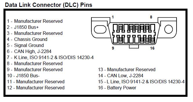
2 2 Table of Contents -- Introduction Product explanation Vehicle Service Information Introduction to On-Board Diagnostics OBD II Diagnostic Link Connector (DLC) Data Link Connector (DLC) Pins OBD II Diagnostic Trouble Codes (DTCs) Using The Scan Tool Keypad Functions Display Functions Getting Started Settings& Adjustments Malfunction Indicator Lamp (MIL) Vehicle Diagnostic Vehicle Diagnostics Read Troubl Codes Erase Trouble Codes View Live Data OBD-II GENERIC OPERATIONAL DATA ITEMS OBD-II GENERIC OPERATIONAL DATA ITEMS (CONT..) View freeze Frame I/M Readiness O2 Monitor Test On-Board Mon. Test Component Test Vehicle Info Modules Present Unit of Measure DTC Lookup Reviev data Print Data Appendix Appendix A PID Definitions Appendix B Glossary Common OBDII DTC Definitions reference
3 3 The Product is: Scanner OEM product Product Features: Codereader Codereader-Pro Scanner Displays the DTC definitions on screen unlike previous models Wider coverage: works with CAN equipped vehicles Reads and clears all generic, and some manufacturer, specific DTCs Yes Yes Yes Yes Yes Yes Yes Yes Yes Resets check engine lights Yes Yes Yes Views OBD II Freeze Frame data Yes Yes Yes Determines the Malfunction Indicator lamp (MIL) status No Yes Yes Displays I/M readiness status No Yes Yes Retrieves the Vehicle Identification Number (VIN) No Yes Yes Scanning live data No Yes Yes Saves scanning Data Yes Yes Yes PC Updata Software Yes Yes Yes Print Data NO NO Yes
4 4 Features: Display: 160x105 pixel LCD with contrast adjustment and backlight Easy to Read screen and also saves up to 38 scans for later viewing. Operating temperature: ( 4 to 122 ) Operation Voltage : DC 9 ~15V provided by vehicle battery Support Protocol: 1) SAE-J1850 PWM 2) SAE-J1850 VPW 3) ISO-14230(KWP2000) 4) ISO ) ISO (CAN BUS)
5 5 Vehicle Service Information The following is a list of web sites and phone numbers where electronic engine control (EEC) diagnostic information is available. Some manuals may be available at your local dealer, auto parts stores or local public libraries. Domestic Vehicles Web Site Phone Number General Motors Chevrolet Pontiac Oldsmobile Buick Cadillac CAD Saturn Ford Ford Lincoln Mercury ChryslerChrysler Dodge Plymouth Eagle Not Available Not Available European Vehicles Audi Volkswagon BMW MINI Jaguar Volvo JAGUAR Mercedes-Benz Land Rover Porsche Saab PORSCHE Asian Vehicles Web Site Phone Number Acura Honda Lexus Scion SCION Toyota GO-TOYOTA Hyundai Infiniti Nissan nissan1
6 6 Kia Mazda Daewoo Subaru SUBARU3 Isuzu Geo Not Available Not Available Mitsubishi MITSU2004 Suzuki
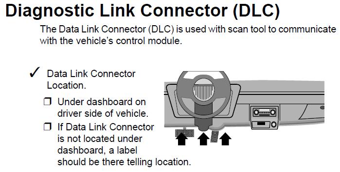
7 7 Introduction to On-Board Diagnostics OBD II On-board diagnostics version II (OBD II) is a system that the Society of Automotive Engineers (SAE) developed to standardize automotive electronic diagnosis. Beginning in 1996, most new vehicles sold in the United States were fully OBD II compliant. SAE Publications Technicians can now use the same tool to test any OBD II compliant vehicle without special adapters. SAE established guidelines that provide: A universal connector, called the DLC, with dedicated pin assignments. A standard location for the DLC, visible under the dash on driver s side. A standard list of diagnostic trouble codes (DTCs) used by all manufacturers. A standard list of parameter identification (PID) data used by all manufacturers. Ability for vehicle systems to record operating conditions when a fault occurs. Expanded diagnostic capabilities that records a code whenever a condition occurs that affects vehicle emissions. Ability to clear stored codes from the vehicle s memory with a Scan Tool. SAE has published hundreds of pages of text defining a standard communication protocol that establishes hardware, software, and circuit parameters of OBD II systems. SAE publishes recommendations, not laws, but the Environmental Protection Agency (EPA) and California Air Resources Board (CARB) made many of SAE s recommendations legal requirements.
8 8
9 9

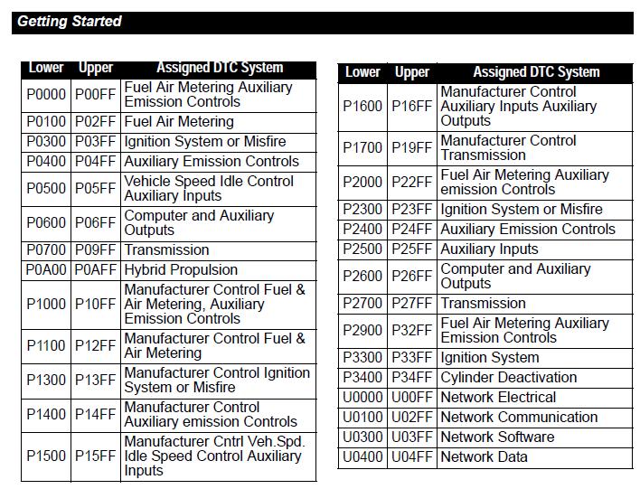
10 Within each category (Powertrain, Chassis, Body and Network) of DTCs there are assigned ranges for different vehicle systems. 10
11 11

12 12 Keypad Functions: Enter button,to perform the selected function of the menu. NO button,for cancelling the operation Or return back by pressing this button. Page-Up roll button Page-Down roll button Right roll button Left roll button

13 13 Display Functions: 1 Diagnostic Trouble Codes Display Area. When the DTC reader found a fault code in the PCM, it will display here. Each fault is assigned a code number that is specific to the fault. 2 PENDING Icon: Indicates the currently display DTC is a Pending Code. 3 DTC Definitions: Information on DTC definitions, Freeze Frame data and test messages are displayed here. 4 DTC Number Sequence: The DTC reader assigns a code sequence number to each DTC found in the vehicle s PCM. The sequence will start from 1. This number will indicate which code is currently displayed. / DTC Enumerator Indicates the total number of codes retrieved from the vehicle s ECU. 5 G/E instruction: Generic DTC / Enhanced DTC 6 LED instruction: Color changing display to indicate the Scan Tool system status. RED Power ON Green - Establish a communication with the vehicle
14 14 Getting Started: Before you use Scan Tool on the vehicle, please ensure that mechanical problems such as low oil level, damaged hoses, wiring or electrical connections are fixed FIRST. They may cause a fault code to set. The following Areas need to be checked before starting any test: The levels of engine oil, power steering fluid, transmission fluid (if auto transmission), engine coolant and other fluids must be at proper level. Top up if necessary. Check the condition of air hoses and the air filter must be cleaned. Replace if necessary. Make sure the timing belts are in good condition and properly tensioned. Make sure the spark plugs are cleaned and in good condition. Check for loose, damaged, disconnected or missing plug cables. Make sure that all mechanical linkages to the engine sensors (throttle, gearshift position, transmission, etc) are secure and properly connected. Refer to Service Manuals for locations. Check all electrical wirings and harnesses for proper connections and condition of its insulation. Check all rubber hoses (radiator) and steel hoses (vacuum and fuel) for leaks, cracks, blockage or other damages. Make sure the engine is mechanically sound. Do a compression check, engine vacuum check, timing check, etc. Always refer to the manufacturer s Service Manual if you are not sure of the repair procedures.
 and make sure that the ignition")


15 15 Settings & Adjustments To enter the MENU Mode: 1. Locate the vehicle Diagnostic Link Connector (DLC) and make sure that the ignition switch is in OFF position 2. Connect the Scan Tool 16PIN cable connector to the vehicle s DLC. If problem of connecting, rotate it to 180 o and try again. 3. Once the Scan Tool is connected to car through the obd2 diagnostic cable, switch iginition ON,the scanner will be powered up and the wake up screen will display as below: 4. Press button it will switch to Main Menu:


16 16 5. Press button to select System Setup 6. Press button to enter, the screen will change to: 7. Select Language option, press button to enter, you can select your favorate language then press YES.


17 17 8. Press button to select Contrast, press, button, will display as follows: Use or to change the Contrast. Then press to return. 9. Unit of Measure: 9. Tool Self-test Once the system has been setted as you desired, press NO button to return to main Menu. 10. Tool Information
 alight.")
18 18 Malfunction Indicator Lamp (MIL): When the vehicle on board computer detects a problem in the emission related systems or components, its diagnostic program will assign a fault code (DTC) and store it in its memory. It also records a Freeze Frame of the conditions present when the fault was found and set the malfunction indicator lamp (MIL) alight. Some faults require detection for two trips in a row before the MIL is turned on. Three typical examples of MIL are shown below: Definition of Trip A Trip is define as a Key-ON, Key-OFF event in which the powertrain control module (PCM) detects the following: Engine coolant temperature should exceed 70 o C Engine coolant temperature should change more than 20 o C after starting the engine. Engine speed should go over 400 RPM. When the powertain control module (PCM) detects a fault during the 1 st trip, the DTC and the corresponding Freeze Frame data are stored in the PCM s memory. The MIL will not light up until the fault is again detected during the 2 nd trip. Certain DTCs are capable of turning the MIL on or blinking during the first trip.


19 19 Vehicle Diagnostics When everything had been confirmed and checked as mentioned in Getting Started, the testing operation can be carried out. 1. Turn the Ignition ON, DO NOT start the engine, select Diagnostics in the Main Menu, press to enter Diagnotic menu, it will display as follows: Note: During linking and diagnosis, the Ling light will be shining in green. 2. Click Yes or No. as you like when asking you whether Erase previous stored data. System Satus


 when emission-related or")

20 20 3.Diagnostic Menu: 3.1 Read Trouble Codes : The READ DTCs function allows the Scan Tool to read the DTCs from the vehicle s control modules. DTCs are used to help determine the cause of a problem or problems in the vehicle. These codes cause the control module to illuminate the malfunction indicator lamp (MIL) when emission-related or driveability fault occurs. MIL is also known as service engine soon or check engine light. 3.2 Erase Trouble Codes The ERASE DTCs function deletes DTCs and I/M Readiness data from vehicle s control module(s). Perform this function with KOEO. Do not start the engine.


21 Live Data The VIEW LIVE DATA function allows real time viewing of the vehicle s computer module s PID data. As the computer monitors the vehicle, information is simultaneously transmitted to scan tool.
22 22 OBD-II GENERIC OPERATIONAL DATA ITEMS Mass Air Flow (Grams/Sec) Range: 0 t o g r / s e c High Perf. Vehicles: 0 to 255 gr/sec Mass air flow sensor input is used by the ECM to calculate fuel delivery. As the air flow increases, the fuel delivery must also increase. Displayed in grams per second. Calculated Load Value Range: 0% to 100% An indication of the current airflow divided by peak airflow, where peak airflow is corrected for altitude, if available. This value is not engine specific. It gives the service technician an indication of the percent of engine capacity being used (with a full load as 100%). Commanded Secondary Air Status Commanded Secondary Air provided to the exhaust system. Engine Coolant Temperature Range: -40 C to 215 C The temperature of the vehicle coolant is used to determine when to transition into closed loop and to calculate spark advance during cold starts. The PCM converts the voltage from the sensor to a temperature. Engine RPM - Engine Speed reading displayed in revolutions per minute. Fuel Pressure (Gage) Range: Fuel pressure of the fuel delivery system. 0 to 765 kpag Fuel System Status-Information describing the operation of the fuel control. Open loop - Operating condition during engine warm up/idle in which the fuel mixture isn t being corrected to compensate for a rich/lean condition. Closed Loop - Operating condition in which the fuel mixture is being corrected for a rich/lean condition. OL Drive - Vehicle in Open Loop due to driving conditions (power enrichment, deceleration). OL Fault - Vehicle in Open Loop due to a detected system fault. CL O2 Fault - Vehicle in Closed Loop, but a fault with at least one oxygen sensor - may be using simple oxygen sensor for fuel control. Ignition Timing Advance Range: -64 to 63.5 The relationship between ignition timing and top dead center, displayed in crankshaft degrees.
23 23 OBD-II GENERIC OPERATIONAL DATA ITEMS (CONT.) Intake Air Temperature Range: -40 C to 215 C Temperature of the air drawn through a cleaner and distributed to each cylinder for use in combustion. Intake Manifold Pressure Range: 10 to 105 kpa, or 0 to 5 Volts The manifold absolute pressure displayed in kilopascals or volts. A low reading will indicate that the pressure is low (vacuum is high) and a high reading will indicate that the pressure is high (vacuum is low). Long Term Fuel Trim (Bank 1 / Bank 2) Long Term adjustments to the Bank 1 fuel calibration schedule which compensate for vehicle differences and gradual changes that occur over time. Range: % to 99.92% (-100% indicating a maximum lean condition, 99.92% indicating a maximum rich condition, and 0% indicating no adjustment). OBD-II Require Requirement level for the On Board Diagnostics designed for the vehicle. OBD-II (CARB) - Vehicle designed with OBD requirements for California Air Resource Board OBD-II. OBD (Fed EPA) - Vehicle designed with OBD requirements for Federal EPA OBD. OBD and OBD-II - Vehicle designed with OBD requirements for OBD and OBD-II. OBD-I - Vehicle designed with OBD requirements for OBD-I. Not Intended - Vehicle not intended to meet any OBD requirements. Oxygen Sensor The detection of Oxygen (O2) content in the exhaust gases. The sensor readings are used by the ECM to help calculate the air-fuel mixture to maintain proper vehicle performance. Short Term Fuel Trim (Bank 1/2) Dynamic or instantaneous adjustments to the Bank 1 base fuel schedule. Range: % to 99.92% (-100% indicating a maximum lean condition, 99.92% indicating a maximum rich condition, and 0% indicating no adjustment). Vehicle Speed (MPH) - Sensor reading displayed in miles per hour.

 function is used to view a snapshot of the operations for the emission system on OBD II vehicles. I/M Readiness is a very useful function.")

24 View Freeze Frame When an emission-related fault occurs, certain vehicle conditions are recorded by the on-board computer. This information is referred to as freeze frame data. VIEW FREEZE FRAME is a snapshot of the operating conditions at the time of an emission-related fault. VIEW FREEZE FRAME can be overwritten by faults with a higher priority. If codes were erased, VIEW FREEZE FRAME may not be stored in vehicle memory depending on vehicle. 3.5 I/M Readiness The I/M Readiness (Inspection / Maintenance) function is used to view a snapshot of the operations for the emission system on OBD II vehicles. I/M Readiness is a very useful function. To guarantee no faults exist make sure all monitors are ok or n/a and no DTC s exist. Refer to the vehicles service manual for the drive cycle operation. During normal driving conditions, the vehicle s computer scans the emission system. After a specific amount of drive time (each monitor has specific driving conditions and time required), the computer s monitors decide if the vehicles emission system is working correctly or not as well as detecting out of range values. When the monitor s status is: Has Run - vehicle was driven enough to complete the monitor. Has Not Run - vehicle was not driven enough to complete the monitor. Don t support- vehicle does not support that monitor. Depending on vehicle, disconnecting or a discharged battery may erase DTCs and clear monitor status. Monitors may be cleared by: Erasing codes


.")
25 25 Vehicle control modules losing power I/M Readiness can be done with the KOER or KOEO. Abbreviations and names for OBD II Monitors supported by the Scan Tool are shown below. They are required by the United States Environmental Protection Agency (EPA). Not all monitors are supported by all vehicles. 3.6 O2 Monitor Test


26 On-Board Mon. Test 3.8 Component Test (not support) 3.9 Vehicle Info. (Can read some of the car model s VIN)


27 Modules Present: show present Protocol 3.11 Unit of Measure


28 Note: When you finish the diagnostics, in the Diganostic Menu, press NO button, then press YES to exist OBDII Test. 28


29 29 DTC Lookup Provide Pxxxx, Uxxxx, Bxxx, Cxxxx DTC s Lookup

30 30 Review Data The scan tool has a record function to track the last testing information. It will begin to diagnose based on previous information when you use it at second time. It s easy for you to operate with this function. The Scan Tool can store the testing information into the interim ROM untill covered by second testing information. It s useful for you to know the historical fault codes before diagnosing.
31 31 Print Data This Function allows you you to send the saved data to computer, and print it. Note: once your work finished, just exit the diagnostic mene, and disconnect the diagnostic cable between Vehicle and MST300.
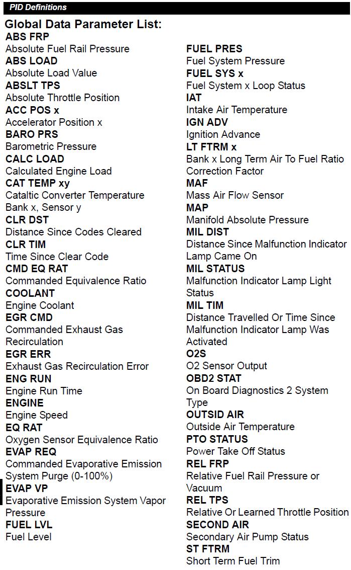
32 32 Appendix A PID Definitions Global PID Definitions All global parameter identification (PID) data listed were verified on actual vehicles to guarantee accuracy. PID definitions were obtained from reliable sources and are accurate at time of printing. It is possible that some newer vehicles may contain data different from what is listed. Always refer to vehicle service manual for manufacturer specific PIDs. Remember, always refer the applicable service manual for detailed diagnostic procedures when troubleshooting PID values. Types of Data Parameters INPUT: OUTPUT: These data parameters are obtained from sensor circuit outputs. Sensor circuit outputs are inputs to the vehicles PCM. For example, if oxygen sensor circuit was generating a 400mV signal, then the code reader would read O2S (v).40. These data parameters are outputs or commands that come directly from control module(s). For example, the ignition spark advance is controlled by PCM, on most vehicles, monitoring this PID shows spark output from PCM. CALCULATED These data parameters are calculated after analyzing VALUE: various inputs to the vehicles control module(s). For example, the engine load. The PCM calculates this from sensor inputs and displays in a percentage. PCM VALUE: Information that is stored in the control module(s) memory and determined to be useful to service technician. An example of this is TROUBLE CODE values, the DTC that caused a freeze frame capture. NOTE: NOTE: Several different causes can have the same parameter indication. For information on diagnostics consult applicable service anuals. The Scan Tool only displays the PID s the vehicle supports.
33 33
34 34 Appendix B Glossary A/C: Air Conditioner A/D: Analog to Digital A/F: Air/Fuel ratio. The proportion of air and fuel delivered to the cylinder for combustion. For example, an A/F ratio of 14:1 denotes 14 times as much air as fuel in the mixture. Ideally the A/F ratio is 14.7:1. ABS: Anti-lock Brake System A/C Clutch Relay: The PCM uses this relay to energize the A/C clutch, turning the A/C compressor on or off. A/C Pressure Sensor: Measures air conditioning refrigerant pressure and sends a voltage signal to the PCM. A/C Pressure Switch: A mechanical switch connected to the A/C refrigerant line. The switch is activated (sending a signal to the PCM) when the A/C refrigerant pressure becomes too low or high. Actuator: Actuators such as relays, solenoids, and motors allow the PCM to control the operation of vehicle systems. Air Injection Reaction (AIR) System: An emission control system operated by the PCM. During cold starts, an air pump injects outside air into the exhaust manifold to help burn hot exhaust gases. This reduces pollution and speeds warm-up of oxygen sensors and catalytic converters. After the engine is warm, the air will either be dumped back to the atmosphere (or into the air cleaner assembly) or sent to the catalytic converter. APP: Acceleration Pedal Position (Sensor) ASR: Acceleration Slip Regulation AFC: Air Flow Control ALDL: Assembly Line Diagnostic Link. Former name for GM (only) Data Link Connector, the connector socket into which the scan tool plug is inserted; sometimes used to refer to any pre-obd II computer signals Bank x: The standard way of referring to the bank of cylinders containing cylinder #x. In-line engines have only one bank of cylinders. Most commonly used to identify the location of oxygen sensors. See O2S, Sensor x, Sensor x. BARO: Barometric Pressure Sensor. See MAP Sensor. BBV: Brake Boost Vacuum (Sensor BCM: Body Control Module Boost Control Solenoid: A solenoid that is energized by the PCM, in order to control turbo/supercharger boost pressure.
35 35 Brake Switch Signal: An input signal to the PCM indicating that the brake pedal is being pressed. This signal is typically used to disengage Cruise Control systems and Torque Converter Clutch (TCC) solenoids. See also TCC. CAM: Camshaft Position Sensor. Sends a frequency signal to the PCM in order to synchronize fuel injector and spark plug firing. Catalytic Converter: Designed to reduce exhaust emissions. CAN: Controller Area Network CARB: California Air Resources Board. Governing body for emissions control in California. CFI: Central Fuel Injection (a.k.a. Throttle Body Fuel Injection TBI) CFI: Continuous Fuel Injection CKP REF: Crankshaft Position Reference. CKP: Crankshaft Position. See CPS. CKT: Circuit Closed Loop (CL): A feedback system that uses the O2 Sensor(s) to monitor the results of combustion. Based on the signal(s) from the O2 sensor(s), the PCM modifies the air/fuel mixture to maintain optimum performance with lowest emissions. In closed loop mode, the PCM can fine tune control of a system to achieve an exact result. CMP: Camshaft Position Sensor CO: Carbon Monoxide; odorless gas produced by incomplete combustion. Code Scanner: A device that interfaces with and communicates information via a data link. Continuous Memory Codes: See Pending Codes. CPS: Crankshaft Position Sensor. Sends a frequency signal to the PCM. It is used to reference fuel injector operation and synchronize spark plug firing on distributorless ignition systems (DIS). CTS: Coolant Temperature Sensor. A resistance sensor that sends a voltage signal to the PCM indicating the temperature of the coolant. This signal tells the PCM whether the engine is cold or warm. CVRTD: Continuous Variable Real Time Damping D/R: Drive/Reverse Data Link Connector (DLC): Connector providing access and/or control of the vehicle information, operating conditions, and diagnostic information. Vehicles with OBD II use a 16-pin connector located in the passenger compartment. Data Stream: The actual data communications sent from the vehicle s PCM to the data connector.
36 DEPS: Digital Engine Position Sensor. Detonation: See Knock. DI/DIS: Direct Ignition/Distributorless Ignition System. A system that produces the ignition spark without the use of a distributor. DPFE: Differential Pressure Feedback Exhaust Gas Recirculation Sensor Driving Cycle - A specific sequence of start-up, warm-up and driving tasks that tests all OBD II functions DTC: Diagnostic Trouble Code. An alphanumeric identifier for a fault condition identified by the On Board Diagnostic System. Duty Cycle: A term applied to signals that switch between on and off. Duty cycle is the percentage of time the signal is on. For example, if the signal is on only one fourth of the time, then the duty cycle is 25%. The PCM uses duty cycle type signals to maintain precise control of an actuator. EBCM: Electronic Brake Control Module EBTCM: Electronic Brake/Traction Control Module ECM Engine Control Module or Electronic Control Module ECT: Engine Coolant Temperature sensor. See CTS. EEPROM or E 2 PROM Electrically Erasable Programmable Read Only Memory EFE: Early Fuel Evaporation EFI: Electronic Fuel Injection. Any system where a computer controls fuel delivery to the engine by using fuel injectors. EGR: Exhaust Gas Recirculation. The PCM uses the EGR system to recirculate exhaust gases back into the intake manifold to reduce emissions. EGR is used only during warm engine cruise conditions. EMR: Electronic Module Retard EOP: Engine Oil Pressure (Switch) EOT Engine Oil Temperature (Sensor) EPA: Environmental Protection Agency. ESC: Electronic Spark Control. An ignition system function that warns the PCM when knock is detected. The PCM then retards spark timing to eliminate the knocking condition. EST: Electronic Spark Timing. An ignition system that allows the PCM to control spark advance timing. The PCM determines optimum spark timing from sensor information engine speed, throttle position, coolant temperature, engine load, vehicle speed, Park/Neutral switch position, and knock sensor condition. EVAP: 36
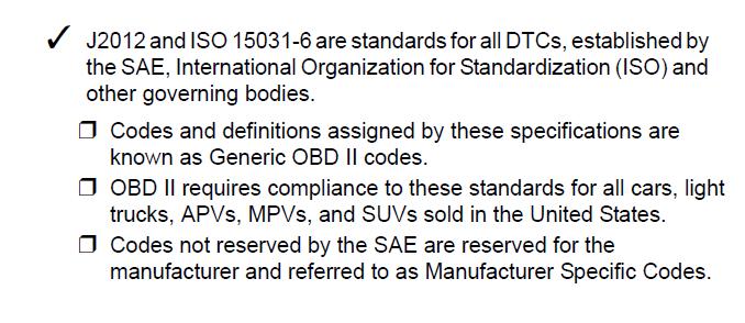
37 37 Evaporative Emissions System. FC: Fan Control Freeze Frame: A block of memory containing DTCs of the vehicle operating conditions for a specific time. FTP: Federal Test Procedure. Strict test of vehicle s emissions. Fuel Trim: Engine computer function that keeps the air/fuel mixture as close to the ideal 14.7:1 stoichiometric ratio as possible Ground (GND): An electrical conductor used as a common return for an electric circuit(s) and with a relative zero potential (voltage). Hall Effect Sensor: Any of a type of sensor utilizing a permanent magnet and a transistorized Hall Effect switch. Hall Effect type sensors may be used to measure speed and position of the crankshaft or camshaft for spark timing and fuel injector control. HC: Hydrocarbons HEI: High Energy Ignition HO2S: Heated Oxygen Sensor. See O2S. HVAC: Heating, Ventilation & Air Conditioning (System) I/M: Inspection and Maintenance. An emission control program. IAC: Idle Air Control. A device mounted on the throttle body which adjusts the amount of air bypassing a closed throttle so that the PCM can control idle speed. IAT: Intake Air Temperature (Sensor) ICM: Ignition Control Module. IMRC: Intake Manifold Runner Control IPC: Instrument Panel Cluster ISC: Idle Speed Control. A small electric motor mounted on the throttle body and controlled by the PCM. The PCM can control idle speed by commanding the ISC to adjust its position. ISO: International Organization of Standardization also know as International Standards Organization. ISO 9141: International Standards Organization OBDII communication mode, used by Chrysler and most foreign cars. One of three hardware layers defined by OBD II J1850PWM: (Pulse Width Modulated) SAE-established OBD II communication standard used by Ford domestic cars and light trucks. One of three hardware layers defined by OBD II J1850VPW: (Variable Pulse Width Modulated) SAE-established OBD II communication standard used by GM cars and light trucks. One of three hardware layers defined by OBD II
38 J1962 SAE: established standard for the connector plug layout used for all OBD II scan tools J1978 SAE: established standard for OBD II scan tools J1979 SAE: established standard for diagnostic test modes J2012 SAE: established standard accepted by EPA as the standard test report language for emission tests KAM: Keep Alive Memory Knock Sensor (KS): Used to detect engine detonation or knock. The sensor contains a piezoelectric element and is threaded into the engine block. Special construction makes the element sensitive only to engine vibrations associated with detonation. Knock: Uncontrolled ignition of the air/fuel mixture in the cylinder. Also referred to as detonation or ping. Knock indicates extreme cylinder pressures or hotspots which are causing the air/fuel mixture to detonate prematurely. KOEO: Key On Engine Off. Turn the ignition key to on, but don t start engine. KOER: Key On Engine Running. Start the vehicle. LCD: Liquid Crystal Display LTFT: Long Term Fuel Trim M/T: Manual transmission or manual transaxle. MAF: Mass Air Flow (sensor). Measures the amount and density of air entering the engine and sends a frequency or voltage signal to the PCM. The PCM uses this signal in its fuel delivery calculations. MAP: Manifold Absolute Pressure (sensor). Measures intake manifold vacuum or pressure and sends a frequency or voltage signal (depending on sensor type) to the PCM. This gives the PCM information on engine load for control of fuel delivery, spark advance, and EGR flow. MAT: Manifold Air Temperature (sensor). A resistance sensor in the intake manifold that sends a voltage signal to the PCM indicating the temperature of the incoming air. The PCM uses this signal for fuel delivery calculations. MIL: Malfunction Indicator Lamp. The MIL is most commonly known as the Check Engine or Service Engine Soon light. A required on-board indicator to alert the driver of an emission-related malfunction. Misfire: Caused by the air fuel ratio being incorrect. Monitor: A test performed by the on-board computer to verify proper operation of emission-related systems or components. MPFI or MFI: Multi-Port Fuel Injection. MPFI is a fuel injection system using one (or more) injector(s) for each cylinder. The injectors are mounted in the intake manifold, and fired in groups rather than individually. NOx: 38
39 39 Oxides of Nitrogen. The system EGR and Camshafts injects exhaust gases into the intake manifold to reduce these gases at the tailpipe. O2S: Oxygen Sensor. Generates a voltage of 0.6 to 1.1 volts when the exhaust gas is rich (low oxygen content). The voltage changes to 0.4 volts or less when the exhaust gas is lean (high oxygen content). This sensor only operates after it reaches a temperature of approximately 349ºC (660ºF). O2 sensors are usually found both upstream and downstream of the catalytic converter. The PCM uses these sensors to fine tune the air-fuel ratio and to monitor the efficiency of the catalytic converter. See Bank 1, Bank 2, Sensor 1, Sensor 2. OBD II: On-Board Diagnostics, Second Generation. OBD II is a U.S. Government-mandated standard requiring all cars and light trucks to have a common data connector, connector location, communication protocol, DTCs and code definitions. OBD II first appeared on vehicles in late 1994, and is required to be present on all cars sold in the US after January 1, ODM: Output Device Monitor. Open Loop (OL): A control system mode that does not monitor the output to verify if the desired results were achieved. A fuel delivery system usually operates in open loop mode during cold engine warm-up because the oxygen sensors are not yet ready to send a signal. Without the oxygen sensor signal, the computer cannot check the actual results of combustion. PCM: Powertrain Control Module. The brains of the engine and transmission control systems housed in a metal box with a number of sensors and actuators connected via a wiring harness. Its job is to control fuel delivery, idle speed, spark advance timing, and emission systems. The PCM receives information from sensors, then energizes various actuators to control the engine. The PCM is also known as the ECM (Engine Control Module). PCV: Positive Crankcase Ventilation Pending Codes: Also referred to as Continuous Memory codes and Maturing Diagnostic Trouble Codes. Pending Codes may be set by emission related powertrain components and systems. If the fault does not occur after a certain number of drive cycles, the code is erased from memory. PID: Parameter Identification. Identifies an address in memory which contains vehicle operating information. PNP: Park/Neutral Position. A switch that tells the PCM when the gear shift lever is in the Park or Neutral position. When in Park or Neutral, the PCM operates the engine in an idle mode. PROM: Programmable Read-Only Memory. The PROM contains programming information the PCM needs to operate a specific vehicle model/engine combination. Proprietary Readings: Parameters shown by on-board computers which are not required by OBD II, but included by manufacturer to assist in trouble-shooting specific vehicles. PSPS: Power Steering Pressure Switch Purge Solenoid: Controls the flow of fuel vapors from the carbon canister to the intake manifold.
40 The canister collects vapors evaporating from the fuel tank, preventing them from escaping to the atmosphere and causing pollution. During warm engine cruise conditions, the PCM energizes the Purge Solenoid so the trapped vapors are drawn into the engine and burned. PTC: Pending Trouble Code PWM: Pulse Width Modulated PZM: Platform Zone Module QDM: Quad Driver Module RAM: Random Access Memory Relay: An electromechanical device in which connections in one circuit are switched. Reluctance Sensor: A type of sensor typically used to measure crankshaft or camshaft speed and/or position, driveshaft speed, and wheel speed. ROM: Read-Only Memory. Permanent programming information stored inside the PCM, containing the information the PCM needs to operate a specific vehicle model/engine combination. RPM: Revolutions Per Minute SAE: Society of Automotive Engineers. Scan Tool: A device that interfaces with and communicates information on a data link. SDM: Sensing and Diagnostic Module Sensor x: A standard term used to identify the location of oxygen sensors. Sensor 1 is located upstream of the catalytic converter. See O2S, Bank 1, Bank 2. Sensor: Any device that reports information to the PCM. The job of the sensor is to convert a parameter such as engine temperature into an electrical signal that the PCM can understand. SES: Service Engine Soon dash light, now referred to as MIL SFI or SEFI: Sequential Fuel Injection or Sequential Electronic Fuel Injection. A fuel injection system that uses one or more injectors for each cylinder. The injectors are mounted in the intake manifold and are fired individually. Solenoid: A device consisting of an electrical coil which when energized, produces a magnetic field in a plunger, which is pulled to a central position. A solenoid may be used as an actuator in a valve or switch. STFT: Short Term Fuel Trim. STS: Service Throttle Soon TAC: Throttle Actuator Control TBI: Throttle Body Injection. A fuel injection system having one or more injectors 40
41 41 mounted in a centrally located throttle body, as opposed to positioning the injectors close to an intake valve port. TBI is also called Central Fuel Injection (CFI) in some vehicles. TCC: Torque Converter Clutch TCM: Transmission Control Module TCS: Traction Control System for PCM and brakes TDC: Top Dead Center. When a piston is at its uppermost position in the cylinder. TFP: Transmission Fluid Pressure TFT: Transmission Fluid Temperature (Sensor) Throttle Body: A device which performs the same function as a carburetor in a fuel injection system. On a throttle body injection (TBI) system, the throttle body is both the air door and the location of the fuel injectors. On port fuel injection systems (PFI, MPFI, SFI, etc.), the throttle body is simply an air door. Fuel is not added until the injectors at each intake port are activated. In each case, the throttle body is attached to the accelerator pedal. TPS: Throttle Position Sensor. Potentiometer-type sensor connected to the throttle shaft. Its voltage signal output increases as the throttle is opened. The PCM uses this signal to control many systems such as idle speed, spark advance, fuel delivery, etc. Traction Assist: Assist in traction with brakes only. Trip: Vehicle operation for a period of time so the systems can be monitored. TTS: Transmission Temperature Sensor. A resistance sensor mounted in the transmission housing in contact with the transmission fluid. It sends a voltage signal to the PCM indicating the temperature of the transmission. VECI: Vehicle Emission Control Information. A decal located in the engine compartment containing information about the emission control systems found on the vehicle. The VECI is the authoritative source for determining whether a vehicle is OBD II compliant. VIN: Vehicle Identification Number. This is the factory-assigned vehicle serial number. This number is stamped on a number of locations throughout the vehicle, but the most prominent location is on top of the dashboard on the driver s side, visible from outside the car. The VIN includes information about the car, including where it was built, body and engine codes, options, and a sequential build number. VSS: Vehicle Speed Sensor. Sends a frequency signal to the PCM. The frequency increases as the vehicle moves faster to give the PCM vehicle speed information used to determine shift points, engine load, and cruise control functions. VTD: Vehicle Theft Deterrent Warm-up Cycle: Warm-up cycle is when the engine coolant temperature rises at least 40 degrees
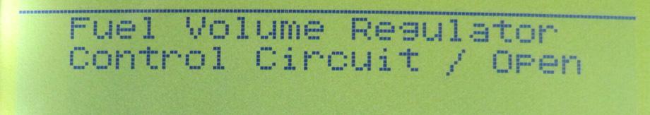
42 42 above that at engine start up. WOT: Wide-Open Throttle. The vehicle operating condition brought about when the throttle is completely (or nearly) open. The PCM typically delivers extra fuel to the engine and de-energizes the A/C compressor at this time for acceleration purposes. The PCM uses a switch or the TPS to identify the WOT condition. Common OBDII DTC Definitions reference (P0xx part): P0000 No Diagnostic Trouble Codes Found P0001 Fuel Volume Regulator Control -Circuit Open P0002 Fuel volume Regulator Control -Circuit Range/Performance P0003 Fuel Volume Regulator Control -Circuit Low P0004 Fuel Volume Regulator Control -Circuit High P0005 Fuel Shut-off Valve -Circuit Open P0006 Fuel Shut-off Valve -Circuit Low P0007 Fuel Shut-off Valve -Circuit High P0008 Engine Position System Performance Bank 1 P0009 Engine Position System Performance Bank 2 P0010 A Camshaft Position Actuator Circuit (Bank 1) P0011 A Camshaft Position - Timing Over-Advanced or System Performance (Bank 1) P0012 A Camshaft Position - Timing Over-Retarded (Bank 1) P0013 B Camshaft Position - Actuator Circuit (Bank 1) P0014 B Camshaft Position - Timing Over-Advanced or System Performance (Bank 1) P0015 B Camshaft Position -Timing Over-Retarded (Bank 1) P0020 A Camshaft Position Actuator Circuit (Bank 2) P0021 A Camshaft Position - Timing Over-Advanced or System Performance (Bank 2) P0022 A Camshaft Position - Timing Over-Retarded (Bank 2) P0023 B Camshaft Position - Actuator Circuit (Bank 2) P0024 B Camshaft Position - Timing Over-Advanced or System Performance (Bank 2) P0025 B Camshaft Position - Timing Over-Retarded (Bank 2) P0030 HO2S Heater Control Circuit (Bank 1 Sensor 1) P0031 HO2S Heater Control Circuit Low (Bank 1 Sensor 1) P0032 HO2S Heater Control Circuit High (Bank 1 Sensor 1) P0033 Turbo Charger Bypass Valve Control Circuit P0034 Turbo Charger Bypass Valve Control Circuit Low P0035 Turbo Charger Bypass Valve Control Circuit High P0036 HO2S Heater Control Circuit (Bank 1 Sensor 2) P0037 HO2S Heater Control Circuit Low (Bank 1 Sensor 2) P0038 HO2S Heater Control Circuit High (Bank 1 Sensor 2) P0042 HO2S Heater Control Circuit (Bank 1 Sensor 3) P0043 HO2S Heater Control Circuit Low (Bank 1 Sensor 3) P0044 HO2S Heater Control Circuit High (Bank 1 Sensor 3) P0050 HO2S Heater Control Circuit (Bank 2 Sensor 1) P0051 HO2S Heater Control Circuit Low (Bank 2 Sensor 1) P0052 HO2S Heater Control Circuit High (Bank 2 Sensor 1) P0056 HO2S Heater Control Circuit (Bank 2 Sensor 2)
43 43 P0057 HO2S Heater Control Circuit Low (Bank 2 Sensor 2) P0058 HO2S Heater Control Circuit High (Bank 2 Sensor 2) P0062 HO2S Heater Control Circuit (Bank 2 Sensor 3) P0063 HO2S Heater Control Circuit Low (Bank 2 Sensor 3) P0064 HO2S Heater Control Circuit High (Bank 2 Sensor 3) P0065 Air Assisted Injector Control Range/Performance P0066 Air Assisted Injector Control Circuit or Circuit Low P0067 Air Assisted Injector Control Circuit High P0070 Ambient Air Temperature Sensor Circuit P0071 Ambient Air Temperature Sensor Range/Performance P0072 Ambient Air Temperature Sensor Circuit Low Input P0073 Ambient Air Temperature Sensor Circuit High Input P0074 Ambient Air Temperature Sensor Circuit Intermittent P0075 Intake Valve Control Solenoid Circuit (Bank 1) P0076 Intake Valve Control Solenoid Circuit Low (Bank 1) P0077 Intake Valve Control Solenoid Circuit High (Bank 1) P0078 Exhaust Valve Control Solenoid Circuit (Bank 1) P0079 Exhaust Valve Control Solenoid Circuit Low (Bank 1) P0080 Exhaust Valve Control Solenoid Circuit High (Bank 1) P0081 Intake valve Control Solenoid Circuit (Bank 2) P0082 Intake Valve Control Solenoid Circuit Low (Bank 2) P0083 Intake Valve Control Solenoid Circuit High (Bank 2) P0084 Exhaust Valve Control Solenoid Circuit (Bank 2) P0085 Exhaust Valve Control Solenoid Circuit Low (Bank 2) P0086 Exhaust Valve Control Solenoid Circuit High (Bank 2) P0100 Mass or Volume Air Flow Circuit P0101 Mass or Volume Air Flow Circuit Range/Performance Problem P0102 Mass or Volume Air Flow Circuit Low Input P0103 Mass or Volume Air Flow Circuit High Input P0104 Mass or Volume Air Flow Circuit Intermittent P0105 Manifold Absolute Pressure/Barometric Pressure Circuit P0106 Manifold Absolute Pressure/Barometric Pressure Circuit Range/Performance Problem P0107 Manifold Absolute Pressure/Barometric Pressure Circuit Low Input P0108 Manifold Absolute Pressure/Barometric Pressure Circuit High Input P0109 Manifold Absolute Pressure/Barometric Pressure Circuit Intermittent P0110 Intake Air Temperature Circuit P0111 Intake Air Temperature Circuit Range/Performance Problem P0112 Intake Air Temperature Circuit Low Input P0113 Intake Air Temperature Circuit High Input P0114 Intake Air Temperature Circuit Intermittent P0115 Engine Coolant Temperature Circuit P0116 Engine Coolant Temperature Circuit Range/Performance Problem P0117 Engine Coolant Temperature Circuit Low Input P0118 Engine Coolant Temperature Circuit High Input P0119 Engine Coolant Temperature Circuit Intermittent P0120 Throttle/Pedal Position Sensor/Switch A Circuit P0121 Throttle/Pedal Position Sensor/Switch A Circuit Range/Performance Problem P0122 Throttle/Pedal Position Sensor/Switch A Circuit Low Input P0123 Throttle/Pedal Position Sensor/Switch A Circuit High Input P0124 Throttle/Pedal Position Sensor/Switch A Circuit Intermittent
44 P0125 Insufficient Coolant Temperature for Closed Loop Fuel Control P0126 Insufficient Coolant Temperature for Stable Operation P0127 Intake Air Temperature Too High P0128 Coolant Thermostat (Coolant Temperature Below Thermostat Regulating Temperature) P0130 O2 Sensor Circuit (Bank 1 Sensor 1) P0131 O2 Sensor Circuit Low Voltage (Bank 1 Sensor 1) P0132 O2 Sensor Circuit High Voltage (Bank 1 Sensor 1) P0133 O2 Sensor Circuit Slow Response (Bank 1 Sensor 1) P0134 O2 Sensor Circuit No Activity Detected (Bank 1 Sensor 1) P0135 O2 Sensor Heater Circuit (Bank 1 Sensor 1) P0136 O2 Sensor Circuit Malfunction (Bank 1 Sensor 2) P0137 O2 Sensor Circuit Low Voltage (Bank 1 Sensor 2) P0138 O2 Sensor Circuit High Voltage (Bank 1 Sensor 2) P0139 O2 Sensor Circuit Slow Response (Bank 1 Sensor 2) P0140 O2 Sensor Circuit No Activity Detected (Bank 1 Sensor 2) P0141 O2 Sensor Heater Circuit (Bank 1 Sensor 2) P0142 O2 Sensor Circuit Malfunction (Bank 1 Sensor 3) P0143 O2 Sensor Circuit Low Voltage (Bank 1 Sensor 3) P0144 O2 Sensor Circuit High Voltage (Bank 1 Sensor 3) P0145 O2 Sensor Circuit Slow Response (Bank 1 Sensor 3) P0146 O2 Sensor Circuit No Activity Detected (Bank 1 Sensor 3) P0147 O2 Sensor Heater Circuit (Bank 1 Sensor 3) P0148 Fuel Delivery Error P0149 Fuel Timing Error P0150 O2 Sensor Circuit (Bank 2 Sensor 1) P0151 O2 Sensor Circuit Low Voltage (Bank 2 Sensor 1) P0152 O2 Sensor Circuit High Voltage (Bank 2 Sensor 1) P0153 O2 Sensor Circuit Slow Response (Bank 2 Sensor 1) P0154 O2 Sensor Circuit No Activity Detected (Bank 2 Sensor 1) P0155 O2 Sensor Heater Circuit (Bank 2 Sensor 1) P0156 O2 Sensor Circuit Malfunction (Bank 2 Sensor 2) P0157 O2 Sensor Circuit Low Voltage (Bank 2 Sensor 2) P0158 O2 Sensor Circuit High Voltage (Bank 2 Sensor 2) P0159 O2 Sensor Circuit Slow Response (Bank 2 Sensor 2) P0160 O2 Sensor Circuit No Activity Detected (Bank 2 Sensor 2) P0161 O2 Sensor Heater Circuit (Bank 2 Sensor 2) P0162 O2 Sensor Circuit Malfunction (Bank 2 Sensor 3) P0163 O2 Sensor Circuit Low Voltage (Bank 2 Sensor 3) P0164 O2 Sensor Circuit High Voltage (Bank 2 Sensor 3) P0165 O2 Sensor Circuit Slow Response (Bank 2 Sensor 3) P0166 O2 Sensor Circuit No Activity Detected (Bank 2 Sensor 3) P0167 O2 Sensor Heater Circuit (Bank 2 Sensor 3) P0168 Fuel Temperature Too High P0169 Incorrect Fuel Composition P0170 Fuel Trim (Bank 1) P0171 System too Lean (Bank 1) P0172 System too Rich (Bank 1) P0173 Fuel Trim Malfunction (Bank 2) P0174 System too Lean (Bank 2) P0175 System too Rich (Bank 2) 44
45 45 P0176 Fuel Composition Sensor Circuit P0177 Fuel Composition Sensor Circuit Range/Performance P0178 Fuel Composition Sensor Circuit Low Input P0179 Fuel Composition Sensor Circuit High Input P0180 Fuel Temperature Sensor A Circuit P0181 Fuel Temperature Sensor A Circuit Range/Performance P0182 Fuel Temperature Sensor A Circuit Low Input P0183 Fuel Temperature Sensor A Circuit High Input P0184 Fuel Temperature Sensor A Circuit Intermittent P0185 Fuel Temperature Sensor B Circuit P0186 Fuel Temperature Sensor B Circuit Range/Performance P0187 Fuel Temperature Sensor B Circuit Low Input P0188 Fuel Temperature Sensor B Circuit High Input P0189 Fuel Temperature Sensor B Circuit Intermittent P0190 Fuel Rail Pressure Sensor Circuit P0191 Fuel Rail Pressure Sensor Circuit Range/Performance P0192 Fuel Rail Pressure Sensor Circuit Low In put P0193 Fuel Rail Pressure Sensor Circuit High Input P0194 Fuel Rail Pressure Sensor Circuit Intermittent P0195 Engine Oil Temperature Sensor P0196 Engine Oil Temperature Sensor Range/Performance P0197 Engine Oil Temperature Sensor Low P0198 Engine Oil Temperature Sensor High P0199 Engine Oil Temperature Sensor Intermittent P0200 Injector Circuit P0201 Injector Circuit - Cylinder 1 P0202 Injector Circuit - Cylinder 2 P0203 Injector Circuit - Cylinder 3 P0204 Injector Circuit - Cylinder 4 P0205 Injector Circuit - Cylinder 5 P0206 Injector Circuit - Cylinder 6 P0207 Injector Circuit - Cylinder 7 P0208 Injector Circuit - Cylinder 8 P0209 Injector Circuit - Cylinder 9 P0210 Injector Circuit - Cylinder 10 P0211 Injector Circuit - Cylinder 11 P0212 Injector Circuit - Cylinder 12 P0213 Cold Start Injector 1 P0214 Cold Start Injector 2 P0215 Engine Shutoff Solenoid P0216 Injector/Injection Timing Control Circuit P0217 Engine Coolant Over Temperature Condition P0218 Transmission Fluid Over Temperature Condition P0219 Engine Over Speed Condition P0220 Throttle/Pedal Position Sensor/Switch B Circuit P0221 Throttle/Pedal Position Sensor/Switch B Circuit Range/Performance Problem P0222 Throttle/Pedal Position Sensor/Switch B Circuit Low Input P0223 Throttle/Pedal Position Sensor/Switch B Circuit High Input P0224 Throttle/Pedal Position Sensor/Switch B Circuit Intermittent P0225 Throttle/Pedal Position Sensor/Switch C Circuit
46 P0226 Throttle/Pedal Position Sensor/Switch C Circuit Range/Performance Problem P0227 Throttle/Pedal Position Sensor/Switch C Circuit Low Input P0228 Throttle/Pedal Position Sensor/Switch C Circuit High Input P0229 Throttle/Pedal Position Sensor/Switch C Circuit Intermittent P0230 Fuel Pump Primary Circuit P0231 Fuel Pump Secondary Circuit Low P0232 Fuel Pump Secondary Circuit High P0233 Fuel Pump Secondary Circuit Intermittent P0234 Turbo/Super Charger Overboost Condition P0235 Turbo/Super Charger Boost Sensor A Circuit P0236 Turbo/Super Charger Boost Sensor A Circuit Range/Performance P0237 Turbo/Super Charger Boost Sensor A Circuit Low P0238 Turbo/Super Charger Boost Sensor A Circuit High P0239 Turbo/Super Charger Boost Sensor B Circuit P0240 Turbo/Super Charger Boost Sensor B Circuit Range/Performance P0241 Turbo/Super Charger Boost Sensor B Circuit Low P0242 Turbo/Super Charger Boost Sensor B Circuit High P0243 Turbo/Super Charger Wastegate Solenoid A P0244 Turbo/Super Charger Wastegate Solenoid A Range/Performance P0245 Turbo/Super Charger Wastegate Solenoid A Low P0246 Turbo/Super Charger Wastegate Solenoid A High P0247 Turbo/Super Charger Wastegate Solenoid B P0248 Turbo/Super Charger Wastegate Solenoid B Range/Performance P0249 Turbo/Super Charger Wastegate Solenoid B Low P0250 Turbo/Super Charger Wastegate Solenoid B High P0251 Injection Pump Fuel Metering Control A (Cam/rotor/Injector) P0252 Injection Pump Fuel Metering Control A Range/Performance (Cam/Rotor/Injector) P0253 Injection Pump Fuel Metering Control A Low (Cam/Rotor/Injector) P0254 Injection Pump Fuel Metering Control A High (Cam/Rotor/Injector) P0255 Injection Pump Fuel Metering Control A Intermittent (Cam/Rotor/Injector) P0256 Injection Pump Fuel Metering Control B (Cam/Rotor/Injector) P0257 Injection Pump Fuel Metering Control B Range/Performance (Cam/Rotor/Injector) P0258 Injection Pump Fuel Metering Control B Low (Cam/Rotor/Injector) P0259 Injection Pump Fuel Metering Control B High (Cam/Rotor/Injector) P0260 Injection Pump Fuel Metering Control B Intermittent (Cam/Rotor/Injector) P0261 Cylinder 1 Injector Circuit Low P0262 Cylinder 1 Injector Circuit High P0263 Cylinder 1 Contribution/Balance P0264 Cylinder 2 Injector Circuit Low P0265 Cylinder 2 Injector Circuit High P0266 Cylinder 2 Contribution/Balance P0267 Cylinder 3 Injector Circuit Low P0268 Cylinder 3 Injector Circuit High P0269 Cylinder 4 Contribution/Balance P0270 Cylinder 4 Injector Circuit Low P0271 Cylinder 4 Injector Circuit High P0272 Cylinder 4 Contribution/Balance P0273 Cylinder 5 Injector Circuit Low 46
OBD-Codes.com Your OBD-II Trouble Codes Repair Site
 Page 1 sur 11 OBD-Codes.com Your OBD-II Trouble Codes Repair Site URL of this page: Like 261 likes. Sign Up to see what your friends like. OBD-II (Check Engine Light) Trouble Codes Welcome to OBD-Codes.com,
Auto Diagnosis Test #7 Review
 Auto Diagnosis Test #7 Review Your own hand written notes may be used for the 1 st 10 minutes of the test Based on Chapters 25, 26, 32, 33, 34 and Lab Demonstrations Auto Diagnosis Test #7 Review Your
Diagnostic Trouble Code (DTC) List - Vehicle
 List - Vehicle") Document ID# 850406 2002 Pontiac Firebird Diagnostic Trouble Code (DTC) List - Vehicle DTC DTC 021 and/or 031 DTC 022 and/or 032 DTC 023 or 033 DTC 24/34 DTC 025 and/or 035 DTC 041 DTC 042 DTC 043 DTC
Document ID# 850406 2002 Pontiac Firebird Diagnostic Trouble Code (DTC) List - Vehicle DTC DTC 021 and/or 031 DTC 022 and/or 032 DTC 023 or 033 DTC 24/34 DTC 025 and/or 035 DTC 041 DTC 042 DTC 043 DTC
Diagnostic Trouble Codes (continued) GM Specific Codes
 GM Specific Codes") 85 GM Specific Codes P11XX Fuel and Air Metering P1106 MAP Sensor Circuit Intermittent High Voltage P1107 MAP Sensor Circuit Intermittent Low Voltage P1108 BARO to MAP Signal Comparison Too High P1111
85 GM Specific Codes P11XX Fuel and Air Metering P1106 MAP Sensor Circuit Intermittent High Voltage P1107 MAP Sensor Circuit Intermittent Low Voltage P1108 BARO to MAP Signal Comparison Too High P1111
 1 User s Manual USER S MANUAL 1 Version: 8.08 Do-It-Auto Table of Contents 1.0 - Introduction -------------------------------------------------------------------------------------- 1.1 The Product ------------------------------------------------------------------------------------------------------------
OBD-II Diagnostic Powertrain (P) Trouble Codes
 Trouble Codes") OBD-II Diagnostic Powertrain (P) Trouble Codes Please use our new & improved search engine to find information on your trouble codes. Search Now! This list contains standard diagnostic trouble codes (DTC
OBD-II Diagnostic Powertrain (P) Trouble Codes Please use our new & improved search engine to find information on your trouble codes. Search Now! This list contains standard diagnostic trouble codes (DTC
Powertrain DTC Summaries EOBD
 Powertrain DTC Summaries Quick Reference Diagnostic Guide Jaguar X-TYPE 2.0 L 2002.25 Model Year Refer to page 2 for important information regarding the use of Powertrain DTC Summaries. Jaguar X-TYPE 2.0
C6 Corvette DIC Codes
 C6 Corvette DIC Codes B0159 Outside Air Temp Sensor B2910 Steering Column Lock Password Incorrect B0164 Pass Compartment Temp Sensor B2981 Right Front Door Handle Switch B0174 Output Air Temp Sensor 1
Powertrain DTC Summaries EOBD
 Powertrain DTC Summaries Quick Reference Diagnostic Guide Jaguar S-TYPE V6, V8 N/A and V8 SC 2002.5 Model Year Refer to pages 2 9 for important information regarding the use of Powertrain DTC Summaries.
UIF Technology CO.,LTD.
 CONTENTS 1. INTRODUCTION MEMOScanner is newly developed by UIF TECH, specially designed for car owners or DIYs. With an MEMOScanner, you may quickly find out trouble causes of electronically controlled
Powertrain DTC Summaries OBD II
 Powertrain DTC Summaries Quick Reference Diagnostic Guide Jaguar X-TYPE 2.5L and 3.0L 2002 Model Year Revised January, 2002: P0706, P0731, P0732, P0733, P0734, P0735, P0740, P1780 POSSIBLE CAUSES Revised
INDEX. 1.Safety Precautions and Warnings...3
 INDEX 1.Safety Precautions and Warnings...3 2. General Information...5 2.1 On-Board Diagnostics (OBD) II... 5 2.2 Diagnostic Trouble Codes (DTCs)... 6 2.3 Location of the Data Link Connector (DLC)...7
01 02B ON-BOARD DIAGNOSTIC [ENGINE CONTROL SYSTEM (FS)]
![01 02B ON-BOARD DIAGNOSTIC [ENGINE CONTROL SYSTEM (FS)]](/thumbs/80/80600627.jpg "01 02B ON-BOARD DIAGNOSTIC [ENGINE CONTROL SYSTEM (FS)]") ON-BOARD DIAGNOSTIC [ENGINE CONTROL SYSTEM (FS)] CONTROL SYSTEM WIRING DIAGRAM [FS]............................ 2 CONTROL SYSTEM DEVICE AND CONTROL RELATIONSHIP CHART [FS]........ 4 Engine Control System............
ON-BOARD DIAGNOSTIC [ENGINE CONTROL SYSTEM (FS)] CONTROL SYSTEM WIRING DIAGRAM [FS]............................ 2 CONTROL SYSTEM DEVICE AND CONTROL RELATIONSHIP CHART [FS]........ 4 Engine Control System............
Powertrain DTC Summaries EOBD
 Powertrain DTC Summaries Quick Reference Diagnostic Guide Jaguar X-TYPE 2.5L and 3.0L 2001.5 Model Year Revised January, 2002: P0706, P0731, P0732, P0733, P0734, P0735, P0740, P1780 POSSIBLE CAUSES Revised
Table of Contents 1. INTRODUCTION GENERAL INFORMATION-ABOUT OBDII/EOBD PRODUCT DESCRIPTIONS OPERATIONS...11
 Table of Contents 1. INTRODUCTION...1 2. GENERAL INFORMATION-ABOUT OBDII/EOBD...1 2.1 ON-BOARD DIAGNOSTICS (OBD) II...1 2.2 DIAGNOSTIC TROUBLE CODES (DTCS)...2 2.3 LOCATION OF THE DATA LINK CONNECTOR (DLC)...3
Service Bulletin. DTC Detection Item Associated Monitor
 Service Bulletin 03-010 Applies To: All OBD II equipped models except SLX March 29, 2003 OBD II DTCs and Their Associated Monitors This is a list of all DTCs for all OBD II models. No one model has all
P0121 Throttle/Pedal Position Sensor/Switch A Circuit Range/Performance Problem
 *** Not all codes apply to all vehicles *** P0100 Mass or Volume Air Flow Circuit Malfunction P0101 Mass or Volume Air Flow Circuit Range/Performance Problem P0101 Mass or Volume Air Flow Circuit Low Input
For. Code Reader. User Manual
 For OBD2 Code Reader User Manual http://www.motodok.com Table of Contents 1. Description... 2 2. Features... 2 3. Getting Started... 3 1. Connect Code Reader to Vehicle's Test Connector... 3 2. Read Diagnostic
ATASA 5 th. Engine Performance Systems. Please Read The Summary. ATASA 5 TH Study Guide Chapter 25 Pages Engine Performance Systems 100 Points
 ATASA 5 TH Study Guide Chapter 25 Pages 725 763 100 Points Please Read The Summary 1. Engine systems are those responsible for how an engine runs. Performance Emission Control Electronic 2. The correct
P Fuel Volume Regulator Control Circuit P Fuel Volume Regulator Control Circuit Range/Performance P Fuel Volume Regulator Control
 P0001 - Fuel Volume Regulator Control Circuit P0002 - Fuel Volume Regulator Control Circuit Range/Performance P0003 - Fuel Volume Regulator Control Circuit Low P0004 - Fuel Volume Regulator Control Circuit
Diagnostic Trouble Code (DTC) memory, checking and erasing
 memory, checking and erasing") Page 1 of 49 01-12 Diagnostic Trouble Code (DTC) memory, checking and erasing Check DTC Memory (function 02) - Connect VAS5051 tester Page 01-7 and select vehicle system "01 - Engine electronics". Engine
Page 1 of 49 01-12 Diagnostic Trouble Code (DTC) memory, checking and erasing Check DTC Memory (function 02) - Connect VAS5051 tester Page 01-7 and select vehicle system "01 - Engine electronics". Engine
ENGINE 01 02A 1. Toc of SCT ON-BOARD DIAGNOSTIC [ENGINE. Toc of SCT 01 02A ON-BOARD DIAGNOSTIC [ENGINE CONTROL SYSTEM (ZM)] 01 02A
![ENGINE 01 02A 1. Toc of SCT ON-BOARD DIAGNOSTIC [ENGINE. Toc of SCT 01 02A ON-BOARD DIAGNOSTIC [ENGINE CONTROL SYSTEM (ZM)] 01 02A](/thumbs/90/103285807.jpg "ENGINE 01 02A 1. Toc of SCT ON-BOARD DIAGNOSTIC [ENGINE. Toc of SCT 01 02A ON-BOARD DIAGNOSTIC [ENGINE CONTROL SYSTEM (ZM)] 01 02A") ENGINE 01 SECTION Toc of SCT ON-BOARD DIAGNOSTIC [ENGINE CONTROL SYSTEM (ZM)]...01-02A ON-BOARD DIAGNOSTIC [ENGINE CONTROL SYSTEM (FS)]...01-02B ON-BOARD DIAGNOSTIC [CRUISE CONTROL SYSTEM].......01-02C
ENGINE 01 SECTION Toc of SCT ON-BOARD DIAGNOSTIC [ENGINE CONTROL SYSTEM (ZM)]...01-02A ON-BOARD DIAGNOSTIC [ENGINE CONTROL SYSTEM (FS)]...01-02B ON-BOARD DIAGNOSTIC [CRUISE CONTROL SYSTEM].......01-02C
ProECU Subaru DIT. DTC List 2012-onward Model Year. v1.0
 ProECU Subaru DIT DTC List 2012-onward Model Year v1.0 Engine DTC List P000A A CAMSHAFT POSITION SLOW RESPONSE (BANK 1) P000B B CAMSHAFT POSITION SLOW RESPONSE (BANK 1) P000C A CAMSHAFT POSITION SLOW RESPONSE
E - THEORY/OPERATION - TURBO
 E - THEORY/OPERATION - TURBO 1995 Volvo 850 1995 ENGINE PERFORMANCE Volvo - Theory & Operation 850 - Turbo INTRODUCTION This article covers basic description and operation of engine performance-related
Five-digit error code First position: P - is for powertrain codes B - is for body codes C - is for chassis codes
 https://www.automotive-manuals.net Five-digit error code First position: P - is for powertrain codes B - is for body codes C - is for chassis codes The second position: 0 - the total for the OBD-II code
2002 ENGINE PERFORMANCE. Self-Diagnostics - RAV4. Before performing testing procedures, check for any related Technical Service Bulletins (TSBs).
.") 2002 ENGINE PERFORMANCE Self-Diagnostics - RAV4 INTRODUCTION NOTE: Before performing testing procedures, check for any related Technical Service Bulletins (TSBs). To properly diagnosis and repair this
2002 ENGINE PERFORMANCE Self-Diagnostics - RAV4 INTRODUCTION NOTE: Before performing testing procedures, check for any related Technical Service Bulletins (TSBs). To properly diagnosis and repair this
Diagnostic Trouble Code (DTC) table
 table") Page 1 of 40 01-19 Diagnostic Trouble Code (DTC) table Note: When malfunctions occur in monitored sensors or components, Diagnostic Trouble Codes (DTCs) are stored in DTC memory with a description of the
Page 1 of 40 01-19 Diagnostic Trouble Code (DTC) table Note: When malfunctions occur in monitored sensors or components, Diagnostic Trouble Codes (DTCs) are stored in DTC memory with a description of the
Lotus Service Notes Section EMR
 ENGINE MANAGEMENT SECTION EMR Lotus Techcentre Sub-Section Page Diagnostic Trouble Code List EMR.1 3 Component Function EMR.2 7 Component Location EMR.3 9 Diagnostic Guide EMR.4 11 CAN Bus Diagnostics;
GM Enhanced Parameters
 GM Enhanced Parameters # of 4x Ref Pulses between CAM Counter # OF EGR ADAPTIVE LEARN MATRIX CELLS OUT OF RANGE High # OF EGR ADAPTIVE LEARN MATRIX CELLS OUT OF RANGE LOW 1-2 Adapt High Cell 1-2 Adapt
2.8 Liter VR6 2V Fuel Injection & Ignition, Engine Code(s): AAA m.y
: AAA m.y") 2.8 Liter VR6 2V Fuel Injection & Ignition, Engine Code(s): AAA m.y. 1996-1997 01 - On Board Diagnostic (OBD) On Board Diagnostic (OBD II) Malfunction Indicator Lamp (MIL) On Board Diagnostic (OBD II),
2.8 Liter VR6 2V Fuel Injection & Ignition, Engine Code(s): AAA m.y. 1996-1997 01 - On Board Diagnostic (OBD) On Board Diagnostic (OBD II) Malfunction Indicator Lamp (MIL) On Board Diagnostic (OBD II),
SAS light Check Engine Malfunction Indicator Lamp
 SAS light Check Engine Malfunction Indicator Lamp Here's how to do it: In car ECM Diagnostics/ECM Reset procedure: 1) Sit in the driver's seat. 2) Turn the ignition key to the ON position and wait three
User s Manual XOB15091 OBD II / EOBD CODE READER. All Rights Reserved. Warranty and Service
 5. Warranty and Service 5.1 Limited One Year Warranty The manufacturer/supplier warranty provided to customers for this product will be free from all defects in materials and workmanship for a period of
DTC P0171, P0172, P0174, or P0175
 Page 1 of 6 2009 Pontiac G8 G8 Service Manual Document ID: 2076050 DTC P0171, P0172, P0174, or P0175 Diagnostic Instructions Perform the Diagnostic System Check - Vehicle prior to using this diagnostic
Ford Gasoline Programmer. Reprogram. Power
 Performance PROGRAMMER Ford Gasoline Programmer 4 Reprogram Power INSTALLATION INSTRUCTIONS OVERVIEW Your vehicle has an onboard computer that controls the engine and transmission. The JET programmer reprograms
MULTIPOINT FUEL INJECTION (MPI) <4G9>
 <4G9>") MULTIPOINT FUEL INJECTION (MPI) 13C-1 MULTIPOINT FUEL INJECTION (MPI) CONTENTS GENERAL................................. 2 Outline of Changes............................ 2 GENERAL INFORMATION...................
MULTIPOINT FUEL INJECTION (MPI) 13C-1 MULTIPOINT FUEL INJECTION (MPI) CONTENTS GENERAL................................. 2 Outline of Changes............................ 2 GENERAL INFORMATION...................
SYTY Trouble Code: ALDL INFORMATION
 SYTY Trouble Code: ALDL INFORMATION A -- Ground G -- Fuel Pump B -- Diagnostic Terminal H -- Brake Sense Speed Input F -- TCC M -- Serial Data (special tool needed - Do Not Use) For ECM Trouble Codes,
ProECU Subaru BRZ Toyota GT86 Scion FR-S
 ProECU Subaru BRZ Toyota GT86 Scion FR-S DTC List 2012-onward Model Year v1.0 Engine DTC List P000A Camshaft Position "A" - Timing Slow Response Bank 1 P000B Camshaft Position "B" - Timing Slow Response
Fuel Metering System Component Description
 1999 Chevrolet/Geo Tahoe - 4WD Fuel Metering System Component Description Purpose The function of the fuel metering system is to deliver the correct amount of fuel to the engine under all operating conditions.
OBDCheck VP30 CAN OBD II SCAN TOOL. User Manual. The Best Solution to Read & Erase Trouble Codes for OBD II Compliant Vehicles.
 OBDCheck VP30 CAN OBD II SCAN TOOL User Manual The Best Solution to Read & Erase Trouble Codes for OBD II Compliant Vehicles. Table of Contents 1. Safety Precautions and Warnings...1 2. General Information
Lotus Service Notes Section EMD
 ENGINE MANAGEMENT SECTION EMD Lotus Techcentre Sub-Section Page Diagnostic Trouble Code List EMD.1 3 Component Function EMD.2 8 Component Location EMD.3 10 Diagnostic Guide EMD.4 11 CAN Bus Diagnostics;
Alternative Fuel Engine Control Unit
 1999 Chevrolet/Geo Cavalier (CNG) Alternative Fuel Engine Control Unit Table 1: AF ECU Function Parameters The (AF ECU) controls alternative fuel engine operation. The control unit monitors various engine
ARTICLE BEGINNING INTRODUCTION SELF-DIAGNOSTIC SYSTEM RETRIEVING DTCS ENGINE PERFORMANCE Volkswagen Self-Diagnostics - Gasoline
 Article Text ARTICLE BEGINNING 1996 ENGINE PERFORMANCE Volkswagen Self-Diagnostics - Gasoline Cabrio, Golf III, GTI, Jetta III, Passat INTRODUCTION If no faults were found while performing preliminary
 Verified Fix #1 Tool Data Diagnostic Trouble Code Information Report Customer #1 VIN: JT8BL69SX4G015327 Customer Name: Year: 2004 Customer Phone#: 123-123-1234 Make: Lexus Report#: 162 Model: GS 430 Date
DTC P0420 or P0430. Circuit Description. DTC Descriptors. Conditions for Running the DTC
 Page 1 of 5 2005 Cadillac STS STS (VIN D) Service Manual Engine Engine Controls - 4.6L (LH2) Diagnostic Information and Procedures DTC P0420 or P0430 Circuit Description A three-way catalytic converter
DIAGNOSTIC TROUBLE CODE CHART HINT:
 DIAGNOSTICS DIAGNOSTIC TROUBLE CODE CHART HINT: SFI SYSTEM (1MZFE) 05241 Parameters listed in the chart may not be exactly the same as your reading due to the type of instrument or other factors. If a
YOU CAN DO IT!... 1 SAFETY PRECAUTIONS SAFETY FIRST!... 2
 Table of Contents YOU CAN DO IT!... 1 SAFETY PRECAUTIONS SAFETY FIRST!... 2 ABOUT THE VEHICLES COVERED... 3 ADJUSTMENTS AND SETTINGS... 4 CONTROLS AND INDICATORS... 6 DISPLAY FUNCTIONS... 7 ONBOARD DIAGNOSTICS
ATASA 5 th. Detailed Diagnosis & Sensors. Please Read The Summary
 ATASA 5 TH Study Guide Chapter 26 Pages 764 809 51 Points Please Read The Summary 1. Many different sensors are involved in the overall driveability of a vehicle. Input Processing Output Electronic Engine
E - THEORY/OPERATION ENGINE PERFORMANCE General Motors Corp. - Theory & Operation - 5.7L
 E - THEORY/OPERATION 1998 ENGINE PERFORMANCE General Motors Corp. - Theory & Operation - 5.7L INTRODUCTION This article covers basic description and operation of engine performance-related systems and
Motronic September 1998
 The Motronic 1.8 engine management system was introduced with the 1992 Volvo 960. The primary difference between this Motronic system and the previous generation of Volvo LH-Jetronic engine management
DIAGNOSTIC TROUBLE CODE CHART
 DIAGNOSTIC TROUBLE CODE CHART HINT: DI231 Parameters listed in the chart may not be exactly the same as your readings due to the type of instrument or other factors. If a malfunction code is displayed
Diagnostic Trouble Codes (continued) Ford Specific Codes
 Ford Specific Codes") 92 Ford Specific Codes P11XX Fuel and Air Metering P1000 OBD-II Monitor Drive Cycle Not Completed P1001 KOER Self-Test Not Completed, Test Aborted P1100 Mass Airflow MAF Sensor Intermittent P1101 Mass
92 Ford Specific Codes P11XX Fuel and Air Metering P1000 OBD-II Monitor Drive Cycle Not Completed P1001 KOER Self-Test Not Completed, Test Aborted P1100 Mass Airflow MAF Sensor Intermittent P1101 Mass
DIAGNOSTIC TROUBLE CODE DEFINITIONS
 DIAGNOSTIC TROUBLE CODE DEFINITIONS DIAGNOSTIC TROUBLE CODE DEFINITIONS DTC Description P0010 Variable Valve Timing Circuit Malfunction (Bank 1) P0020 Variable Valve Timing Circuit Malfunction (Bank 2)
GROUP 13Ab. 13Ab-2 CONTENTS TROUBLESHOOTING STRATEGY.. DATA LIST REFERENCE TABLE... 13Ab-29 TROUBLE CODE DIAGNOSIS...
 13Ab-1 GROUP 13Ab CONTENTS TROUBLESHOOTING STRATEGY.. 13Ab-2 DATA LIST REFERENCE TABLE... 13Ab-29 TROUBLE CODE DIAGNOSIS..... 13Ab-2 FAIL-SAFE FUNCTION REFERENCE TABLE........................ 13Ab-20 DIAGNOSTIC
G - TESTS W/CODES - 2.2L
 G - TESTS W/CODES - 2.2L 1994 Toyota Celica 1994 ENGINE PERFORMANCE Toyota 2.2L Self-Diagnostics Celica INTRODUCTION If no faults were found while performing F - BASIC TESTING, proceed with self-diagnostics.
INTRODUCTION WHAT IS OBD?... 1 YOU CAN DO IT!... 2 SAFETY PRECAUTIONS SAFETY FIRST!... 3
 Table of Contents INTRODUCTION WHAT IS OBD?... 1 YOU CAN DO IT!... 2 SAFETY PRECAUTIONS SAFETY FIRST!... 3 ABOUT THE CODE READER VEHICLES COVERED... 4 CONTROLS AND INDICATORS... 5 DISPLAY FUNCTIONS...
P0046 Turbo/Super Charger Boost Control Solenoid Circuit Range/Performance P0069 MAP/BARO Correlation P0096 Intake Air Temperature Sensor 2 Circuit
 P0046 Turbo/Super Charger Boost Control Solenoid Circuit Range/Performance P0069 MAP/BARO Correlation P0096 Intake Air Temperature Sensor 2 Circuit Range/Performance P0097 Intake Air Temperature Sensor
ABOUT THE DIAGNOSTIC TOOL
 Table of Contents INTRODUCTION WHAT IS OBD?... 1 YOU CAN DO IT!... 2 SAFETY PRECAUTIONS SAFETY FIRST!... 3 ABOUT THE DIAGNOSTIC TOOL VEHICLES COVERED... 5 BATTERY REPLACEMENT... 6 DIAGNOSTIC TOOL CONTROLS
C5 Computer Diagnostic Codes
 C5 Computer Diagnostic Codes The ability to view engine operating data such as oil pressure and coolant temperature, in digital form on the instrument panel has been a feature of Corvettes since 1984.
YOU CAN DO IT!... 1 SAFETY PRECAUTIONS SAFETY FIRST!... 2
 Table of Contents YOU CAN DO IT!... 1 SAFETY PRECAUTIONS SAFETY FIRST!... 2 ABOUT THE SCAN TOOL VEHICLES COVERED... 3 CONTROLS AND INDICATORS... 4 DISPLAY FUNCTIONS... 5 DISPLAY AND SETTINGS... 6 ONBOARD
YOU CAN DO IT!... 1 SAFETY PRECAUTIONS SAFETY FIRST!... 2
 Table of Contents YOU CAN DO IT!... 1 SAFETY PRECAUTIONS SAFETY FIRST!... 2 ABOUT THE CODE READER VEHICLES COVERED... 3 CONTROLS AND INDICATORS... 4 DISPLAY FUNCTIONS... 5 ONBOARD DIAGNOSTICS COMPUTER
Table of Contents. CarScan+OBD1
 Table of Contents INTRODUCTION WHAT IS OBD?... 1 YOU CAN DO IT!... 2 SAFETY PRECAUTIONS SAFETY FIRST!... 3 ABOUT THE SCAN TOOL VEHICLES COVERED... 5 BATTERY REPLACEMENT... 6 SCAN TOOL CONTROLS CONTROLS
OBD2DISPLAY MANUAL. 195 mm Length, 81 mm Width, 32 mm Height, OBDII connector + cable 1500 mm
 OBD2DISPLAY MANUAL 1. SAFETY PRECAUTIONS AND WARNINGS To prevent personal injury or damage to vehicles or the car tool, read this instruction manual first and observe the following safety precautions.
DTC Summaries. NipponDenso V12 Engine Management
 DTC Summaries NipponDenso V12 Engine Management OBD II MONITORING CONDITIONS: When testing for DTC reoccurrence, it can be determined if the Service Drive Cycle was of sufficient length by performing a
ATS Diesel Performance 5293 Ward Road Arvada, CO E-Power Programmer. Toll free
 ATS Diesel 5293 Ward Road Arvada, CO. 80002 www.atsdiesel.com Duramax Dodge Ram 2004.5-2006 2003-2005 E-Power Programmer Toll free 800.949.6002 DISCLAIMER OF LIABILITY This is a performance product which
Lotus Service Notes Section EMQ
 ENGINE MANAGEMENT SECTION EMQ Lotus Techcentre Sub-Section Page Component Function EMQ.1 3 Component Location EMQ.2 5 Diagnostic Trouble Code List EMQ.3 7 Diagnostic Guide EMQ.4 11 CAN Bus Diagnostics;
2UZ-FE ENGINE CONTROL SYSTEM SFI SYSTEM
 160 2UZ-FE EINE CONTROL SYSTEM SFI SYSTEM DTC P0171 System Too Lean (Bank 1) DTC P0172 System Too Rich (Bank 1) DTC P0174 System Too Lean (Bank 2) DTC P0175 System Too Rich (Bank 2) DCRIPTION The fuel
MULTIPORT FUEL SYSTEM (MFI) <2.4L ENGINE>
 <2.4L ENGINE>") 13A-1 GROUP 13A MULTIPORT FUEL SYSTEM (MFI) CONTENTS GENERAL DESCRIPTION......... 13A-2 FUEL INJECTION CONTROL...... 13A-5 THROTTLE VALVE OPENING ANGLE CONTROL..................... 13A-6
13A-1 GROUP 13A MULTIPORT FUEL SYSTEM (MFI) CONTENTS GENERAL DESCRIPTION......... 13A-2 FUEL INJECTION CONTROL...... 13A-5 THROTTLE VALVE OPENING ANGLE CONTROL..................... 13A-6
Table of Contents. 3120f
 Table of Contents INTRODUCTION WHAT IS OBD?... 1 YOU CAN DO IT!... 2 SAFETY PRECAUTIONS SAFETY FIRST!... 3 ABOUT THE DIAGNOSTIC TOOL VEHICLES COVERED... 5 BATTERY REPLACEMENT... 6 DIAGNOSTIC TOOL CONTROLS
DTC P0172 Fuel Trim System Rich
 Page 1 of 6 1997 Chevrolet Cavalier Cavalier, Sunfire (VIN J) Service Manual Document ID: 47788 DTC P0172 Fuel Trim System Rich System Description A Closed Loop air/fuel metering system is used to provide
Ford Gasoline Programmer
 Performance PROGRAMMER Ford Gasoline Programmer 4 JET Performance Products 17491 Apex Circle, Huntington Beach, CA 92647 (714) 848-5515 Fax: (714) 847-6290 2008 JET Performance Products JET P/N 15043 08/08
P1157 HO2S Bank 2 Sensor 2 Lean System or Low Voltage P1158 HO2 Sensor Shift Rich (Bank 2 Sensor 2)/ Engine Metal Over-Temperature Protection P1159
/ Engine Metal Over-Temperature Protection P1159") GM OBDII DTC P1031 H02 Sensor Heater Control Circuit Problem P1032 HO2S Heater Warm Up Control Circuit Banks 1 and 2 Sensor 1 P1079 Flexible Fuel Sensor Circuit High Input P1105 Secondary Vacuum Sensor
GM OBDII DTC P1031 H02 Sensor Heater Control Circuit Problem P1032 HO2S Heater Warm Up Control Circuit Banks 1 and 2 Sensor 1 P1079 Flexible Fuel Sensor Circuit High Input P1105 Secondary Vacuum Sensor
INTRODUCTION WHAT IS OBD?... 1 YOU CAN DO IT!... 2 SAFETY PRECAUTIONS SAFETY FIRST!... 3
 Table of Contents INTRODUCTION WHAT IS OBD?... 1 YOU CAN DO IT!... 2 SAFETY PRECAUTIONS SAFETY FIRST!... 3 ABOUT THE CODE READER VEHICLES COVERED... 5 BATTERY REPLACEMENT... 6 ADJUSTMENTS/SETTINGS AND
C5 Corvette IPC Diagnostic Display Mode
 C5 Corvette IPC Diagnostic Display Mode The IPC display, the 20-character, vacuum florescent screen above the steering column that says "Corvette by Chevrolet" every time you turn on the key is a powerful
ENGINE (DIAGNOSTICS) EN(SOHC)
 EN(SOHC)") EN(SOHC) Page 1. Basic Diagnostic Procedure...2 2. Check List for Interview...4 3. General Description...6 4. Electrical Components Location...9 5. Engine Control Module (ECM) I/O Signal...22 6. Engine
EN(SOHC) Page 1. Basic Diagnostic Procedure...2 2. Check List for Interview...4 3. General Description...6 4. Electrical Components Location...9 5. Engine Control Module (ECM) I/O Signal...22 6. Engine
On Board Diagnostics (OBD) Monitors
 Monitors") 2007 PCED On Board Diagnostics SECTION 1: Description and Operation Procedure revision date: 03/29/2006 On Board Diagnostics (OBD) Monitors OBD-I, OBD-II and Engine Manufacturer Diagnostics (EMD) Overview
2007 PCED On Board Diagnostics SECTION 1: Description and Operation Procedure revision date: 03/29/2006 On Board Diagnostics (OBD) Monitors OBD-I, OBD-II and Engine Manufacturer Diagnostics (EMD) Overview
INTRODUCTION WHAT IS OBD?... 1 YOU CAN DO IT!... 2
 Table of Contents INTRODUCTION WHAT IS OBD?... 1 YOU CAN DO IT!... 2 ABOUT THE SCAN TOOL SAFETY FIRST!... 3 VEHICLES COVERED... 4 CONTROLS AND INDICATORS... 5 DISPLAY FUNCTIONS... 6 INITIAL ADJUSTMENTS...
TroubleCodes.net- engine & OBD2 Trouble Codes and Technical info & Tool Store.
 Page 1 sur 8 advertisement Articles / SAFETY / TOOL STORE!! / BAT Support / Search / Help / Guestbook / About Us / Contact Us Forums Navigation Links & Technical Trouble Codes Sunday, January 23, 2005
2002 Buick Rendezvous - AWD
 2002 Buick Rendezvous - AWD DTC P0410 Description The control module activates the secondary air injection (AIR) system by grounding both the pump relay and the vacuum control solenoid control circuits.
OBD II Data Interpretation
 OBD II Data Interpretation What is OBDII? OBDII stands for on board diagnostics second generation superseding that of OBD1.OBDII is a system that was mandated by the Federal EPA and was developed by the
DTC P1415 Secondary Air Injection (AIR) System Bank 1
 System Bank 1") Page 1 of 5 2000 GMC Truck GMC K Sierra - 4WD Sierra, Silverado, Suburban, Tahoe, Yukon (VIN C/K) Service Manual Document ID: 546887 DTC P1415 Secondary Air Injection (AIR) System Bank 1 Circuit Description
Page 1 of 5 2000 GMC Truck GMC K Sierra - 4WD Sierra, Silverado, Suburban, Tahoe, Yukon (VIN C/K) Service Manual Document ID: 546887 DTC P1415 Secondary Air Injection (AIR) System Bank 1 Circuit Description
MULTIPOINT FUEL INJECTION (MPI) <4G63-Turbo>
 <4G63-Turbo>") 13B-1 GROUP 13B MULTIPOINT FUEL INJECTI (MPI) CTENTS GENERAL INFORMATI........ 13B-2 SENSOR....................... 13B-8 THROTTLE VALVE OPENING ANGLE CTROL.............. 13B-9 FUEL INJECTI
13B-1 GROUP 13B MULTIPOINT FUEL INJECTI (MPI) CTENTS GENERAL INFORMATI........ 13B-2 SENSOR....................... 13B-8 THROTTLE VALVE OPENING ANGLE CTROL.............. 13B-9 FUEL INJECTI
GROUP 13Ab. 13Ab-2 CONTENTS TROUBLESHOOTING STRATEGY.. DATA LIST REFERENCE TABLE... 13Ab-28 TROUBLE CODE DIAGNOSIS...
 13Ab-1 GROUP 13Ab CONTENTS TROUBLESHOOTING STRATEGY.. 13Ab-2 DATA LIST REFERENCE TABLE... 13Ab-28 TROUBLE CODE DIAGNOSIS..... 13Ab-2 FAIL-SAFE/BACKUP FUNCTION TABLE........................ 13Ab-20 DIAGNOSTIC
EMISSION CONTROL (AUX. EMISSION CONTROL DEVICES) H4DOTC
 H4DOTC") EMISSION CONTROL (AUX. EMISSION CONTROL DEVICES) H4DOTC SYSTEM OVERVIEW 1. System Overview There are three emission control systems, which are as follows: Crankcase emission control system Exhaust emission
EMISSION CONTROL (AUX. EMISSION CONTROL DEVICES) H4DOTC SYSTEM OVERVIEW 1. System Overview There are three emission control systems, which are as follows: Crankcase emission control system Exhaust emission
PREPARATION FOR TESTING
 Table of Contents INTRODUCTION WHAT IS OBD?... 1 YOU CAN DO IT!... 2 SAFETY PRECAUTIONS SAFETY FIRST!... 3 ABOUT THE FIXADVISOR VEHICLES COVERED... 5 BATTERY REPLACEMENT... 6 ADJUSTMENTS AND SETTINGS...
Powertrain Control Software
 2007 PCED On Board Diagnostics SECTION 1: Description and Operation Procedure revision date: 03/29/2006 Powertrain Control Software Computer Controlled Shutdown The powertrain control module (PCM) controls
Chapter 20 OBD-II Diesel Monitors
 Light Vehicle Diesel Engines First Edition Chapter 20 OBD-II Diesel Monitors LEARNING OBJECTIVES (1 of 2) 20.1 Prepare for the Light Vehicle Diesel Engine (A9) ASE certification fuel system diagnosis and
YOU CAN DO IT! SAFETY PRECAUTIONS
 Table of Contents INTRODUCTION WHAT IS OBD?... 1 YOU CAN DO IT!... 2 SAFETY PRECAUTIONS SAFETY FIRST!... 3 ABOUT THE FIXADVISOR PRO VEHICLES COVERED... 5 BATTERY REPLACEMENT... 6 ADJUSTMENTS AND SETTINGS...
Diagnostic Trouble Codes (continued) SAE Defined Codes
 SAE Defined Codes") 78 SAE Defined Codes P01XX Fuel and Air Metering P0100 Mass or Volume Airflow Circuit Problem P0101 Mass or Volume Airflow Circuit Range or Performance Problem P0102 Mass or Volume Airflow Circuit Low
78 SAE Defined Codes P01XX Fuel and Air Metering P0100 Mass or Volume Airflow Circuit Problem P0101 Mass or Volume Airflow Circuit Range or Performance Problem P0102 Mass or Volume Airflow Circuit Low
MULTIPORT FUEL SYSTEM (MFI) <2.4L ENGINE>
 <2.4L ENGINE>") 13B-1 GROUP 13B MULTIPORT FUEL SYSTEM (MFI) CONTENTS GENERAL DESCRIPTION 13B-2 CONTROL UNIT 13B-5 SENSOR 13B-7 ACTUATOR 13B-24 FUEL INJECTION CONTROL 13B-31 IGNITION TIMING AND CONTROL FOR
13B-1 GROUP 13B MULTIPORT FUEL SYSTEM (MFI) CONTENTS GENERAL DESCRIPTION 13B-2 CONTROL UNIT 13B-5 SENSOR 13B-7 ACTUATOR 13B-24 FUEL INJECTION CONTROL 13B-31 IGNITION TIMING AND CONTROL FOR
DI 3 ENGINE DIAGNOSTICS DI PRE CHECK
 FI0534 PRECHECK DI3 DI09603 1. DIAGNOSIS SYSTEM (a) Description When troubleshooting OBD II vehicles, the only difference from the usual troubleshooting procedure is that you connect to the vehicle the
Diagnostic Trouble Code (DTC) Root Cause. for Omnitek ECM 64A/66A/88A. & Remedial Action
 Root Cause. for Omnitek ECM 64A/66A/88A. & Remedial Action") Diagnostic Trouble Code (DTC) Root Cause & Remedial Action for Omnitek ECM 64A/66A/88A Omnitek Engineering Corp. 1945 S Rancho Santa Fe Rd. San Marcos, CA 92078 Tel. 760-591-0089 - Fax. 760-591-0880 -
Diagnostic Trouble Code (DTC) Root Cause & Remedial Action for Omnitek ECM 64A/66A/88A Omnitek Engineering Corp. 1945 S Rancho Santa Fe Rd. San Marcos, CA 92078 Tel. 760-591-0089 - Fax. 760-591-0880 -
EMISSION CONTROL SYSTEMS
 DN EMISSION CONTROL SYSTEMS 25-1 EMISSION CONTROL SYSTEMS TABLE OF CONTENTS page page ON-BOARD DIAGNOSTICS... 1 EVAPORATIVE EMISSION CONTROLS... 24 ON-BOARD DIAGNOSTICS TABLE OF CONTENTS page DESCRIPTION
MULTIPOINT FUEL INJECTION (MPI) <4G63-Non-Turbo>
 <4G63-Non-Turbo>") 13A-1 GROUP 13A MULTIPOINT FUEL INJECTI (MPI) CTENTS GENERAL INFORMATI........ 13A-2 FUEL INJECTI CTROL...... 13A-6 IDLE SPEED CTROL (ISC)..... 13A-7 IGNITI TIMING AND DISTRIBUTI CTROL........
13A-1 GROUP 13A MULTIPOINT FUEL INJECTI (MPI) CTENTS GENERAL INFORMATI........ 13A-2 FUEL INJECTI CTROL...... 13A-6 IDLE SPEED CTROL (ISC)..... 13A-7 IGNITI TIMING AND DISTRIBUTI CTROL........
The PCM is the on-board computer which receives input from various sensors and, with this information, controls various engine & emissions control
 The PCM is the on-board computer which receives input from various sensors and, with this information, controls various engine & emissions control actuators. The PCM has various memories within it. These
Lotus Service Notes Section EMQ
 ENGINE MANAGEMENT SECTION EMQ Lotus Techcentre Sub-Section Page Cylinder Numbering 2 Component Function EMQ.1 3 Component Location EMQ.2 5 Diagnostic Trouble Code List EMQ.3 7 Diagnostic Guide EMQ.4 11
For Troubleshooting of DTC related components, see chart on page INTAKE AIR BYPASS (IAB) HIGH CONTROL SOLENOID
 HIGH CONTROL SOLENOID") Index For Troubleshooting of DTC related components, see chart on page 11-53. '96-99 models: EXHAUST GAS RECIRCULATION (EGR) and LIFT MANIFOLD ABSOLUTE PRESSURE (MAP) INTAKE AIR BYPASS (IAB) HIGH page
Index For Troubleshooting of DTC related components, see chart on page 11-53. '96-99 models: EXHAUST GAS RECIRCULATION (EGR) and LIFT MANIFOLD ABSOLUTE PRESSURE (MAP) INTAKE AIR BYPASS (IAB) HIGH page
DTC P0420. Circuit Description. Conditions for Running the DTC.
 Page 1 of 5 DTC P0420 2003 Buick LeSabre LeSabre (VIN H) Service Manual Document ID: 792202 Circuit Description In order to control emissions of hydrocarbons (HC), carbon monoxide (CO), and oxides of nitrogen
JACKAROO TIPS Understanding the MIL fault codes on a Jackaroo Turbo Diesel
 JACKAROO TIPS Understanding the MIL fault codes on a Jackaroo Turbo Diesel The Jackaroo, as with all vehicles intended to be supplied to the USA market, (as the Isuzu Trooper) is fitted with OnBoard Diagnostics
Appendix B. Data Parameters. Current and Past TMC Engines Covered in this Section. Fig. B-1. TL874fB01. Engine Control Systems II - Course 874 B-1
 Data Parameters Current and Past TMC Engines Covered in this Section Fig. B-1 TL874fB01 Engine Control Systems II - Course 874 B-1 OBD Data Parameters Signal Category Display Item Parameter Description
5. Control System CONTROL SYSTEM FUEL INJECTION (FUEL SYSTEM) A: GENERAL FU(H4DOTC)-29
 A: GENERAL FU(H4DOTC)-29") W1860BE.book Page 29 Tuesday, January 28, 2003 11:01 PM 5. Control System A: GENERAL The ECM receives signals from various sensors, switches, and other control modules. Using these signals, it determines
W1860BE.book Page 29 Tuesday, January 28, 2003 11:01 PM 5. Control System A: GENERAL The ECM receives signals from various sensors, switches, and other control modules. Using these signals, it determines