LS200 Procedure Light
|
|
|
- Dayna Pitts
- 6 years ago
- Views:
Transcription
1 SERVICE MANUAL LS200 Procedure Light MODELS: Domestic Europe U.K Australia Wall Mount Mobile Stand Copyright 1995 Welch Allyn Co State Street Road P.O. Box 220 Skaneateles Falls, NY Originator: RJS SERVICE MANUAL REV A, 9/94 ECN# /94 1
2 TABLE OF CONTENTS FORWARD 3 SAFE SERVICE 4 INDEX: ELECTRICAL FAILURE/CAUSE/CORRECTIVE ACTION 5-7 MECHANICAL FAILURE/CAUSE/CORRECTIVE ACTION 8-11 INDEX: REMOVAL/REPLACEMENT (R & R) PROCEDURES 12 REMOVAL/REPLACEMENT PROCEDURES APPENDIX SERVICE PARTS LIST AND DIAGRAM WIRING DIAGRAM/SCHEMATIC TOOLS (COMMON & SPECIAL) PRODUCT UP-DATES PRODUCT DESCRIPTION AA BB CC DD EE 2
3 FORWARD This SERVICE MANUAL provides technical assistance to Welch Allyn repair technicians for diagnosing, repairing, and testing the WELCH ALLYN LS200 PROCEDURE LIGHT. The manual s main content areas cover: troubleshooting, step by step repair, adjustment, and re-test procedures. The repair TASK procedures (R & R.. Removal and Replacement) are written to provide quick and easy reference for repair technicians of different experience levels. Required specifications and materials are listed at each step where applicable. When reading this manual for the first time, have an LS200 readily available for reference and practice. Read each complete repair step on what to do (task statement), plus how to do it (technique statement) before starting the repair or practice. Training for the LS200 should consist of detailed demonstrations of required repair tasks, practice on LS200 S using repair tooling and materials. Assess skill development through observation of trainee practice on actual equipment. Set up sessions to allow the trainee to practice the use of the diagnostic, repair, adjustment, and re-testing procedures found in this manual. The ability of the technician to develop and retain new skills is in great part dependent on well prepared training exercises. Each trainee must have the opportunity to practice the procedure(s) after it has been demonstrated by the instructor. More detailed background product information is found in the APPENDIX section and as such will be a critical element in a comprehensive service training program for technicians. I M P O R T A N T : Welch Allyn part numbers and M (material) numbers appearing in this manual are for the purpose of familiarizing new technicians with Welch Allyn documentation conventions. Order replacement parts, as always, by referencing your latest bill of materials, parts catalog and assembly drawings. Part number changes, product updates, or new test procedures should be noted on the appropriate page of this manual by the manual owner. Notices announcing these changes should be attached to PRODUCT UPDATES APPENDIX. 3
4 WEAR EYE PROTECTION WHEN SERVICING THIS PRODUCT! *** SAFE SERVICE *** DISCONNECT power cord from A.C. power source before initial disassembly of LS200 Light. OBSERVE cautions / warnings in owners manual and printed on the product itself. COMPLY with all safety codes and practices for this type of product. COMPLY with all safety regulations at your work place. PERFORM all recommended Welch Allyn service test procedures to assure the LS200 meets all requirements safely and reliably. EXAMINE AND REPAIR OR REPLACE as required, any and all worn or questionable wiring, components, connections, connectors, warning labels, insulation and other items necessary for the continued safe operation of this product. DO NOT TOUCH halogen lamps or nearby parts during or immediately after operation. WAIT AT LEAST TWENTY MINUTES (20 MIN.) BEFORE TOUCHING HALOGEN LAMPS OR METAL NEAR THE LAMP(S). VERY HIGH TEMPERATURES will cause severe burns! Fractured or broken lamps may cause injury. To prevent cuts, REMOVE such lamps by HOLDING them with a cloth or wear work gloves. WEAR SAFETY GLASSES! DO NOT LOOK DIRECTLY AT, TOUCH OR SPRAY LIT halogen lamps. *** QUALITY SERVICE *** MODIFY your SERVICE Manual by notating changes and revisions of part numbers and procedures. Enter this information on the appropriate page...and include a copy of the notification in your Appendix Product Updates. READ AND UNDERSTAND customer comments and complaints on accompanying documentation (P.O. or other correspondence). IF AN INJURY OR ILLNESS TO PATIENT OR USER, OR HAZARDOUS MALFUNCTION HAS OCCURRED OR IS SUSPECTED, DO NOT DISASSEMBLE, REASSEMBLE, ALTER OR REPAIR THE PRODUCT IN ANY WAY...INSTEAD, GIVE THE UNIT AND ALL ACCOMPANYING PAPERWORK TO YOUR REPAIR SUPERVISOR. Appropriate action per approved Welch Allyn policy will be taken. When performing a complete inspection, LOOK for : missing parts, product defects, damage, tampering, unsafe condition of wiring or any component. ENTER all findings and test data along with repair status in the appropriate file. Most of the repairs can be performed on a foam covered work bench. Place the LS200 in holding fixture for repairs. Take all actions to prevent scratching the bezel. 4
5 INDEX: FAILURE / CAUSE LS200 ELECTRICAL COMPLAINT / (CONDITION): CAUSE / CORRECTIVE ACTION: Less than 3 lamps light.... lamp is burned out. REPLACE PN lamp not seated correctly. SEAT lamp. (3 lamps are wired in parallel)... lamp socket defective. REPLACE. None of the lamps illuminate... no voltage at A.C. source. TRY other power outlet. (SWITCH IS ON, POWER RESTORE power. CORD PLUGGED IN)... power cord loose. RESTORE connections... fuse(s) blown. CHECK for short to ground or other high current path such as a line to line short. RESTORE circuit to specifications prior to energizing LS200. REPLACE fuses. WARNING:... burned out lamps. CHECK lamps...are they correct ALLOW LAMPS TO COOL FOR part# for this Light. REPLACE lamp (Welch Allyn at least 20 MINUTES. PN 06400).... defective (failed open) switch. CHECK voltage across switch pole pairs in closed position. If full transformer voltage is present, then the switch is OPEN electrically. REPLACE defective switch. TEST.... defective transformer, OPEN primary or secondary windings or defective or failed OPEN thermal protection* device in transformer primary winding for international LS200. CHECK for continuity in transformer primary winding. REPLACE if open. * non-resetting type does not reset upon cooling.... OPEN circuit in power connector. REPLACE defective component.... power cord damaged. REPLACE cord. 5
6 INDEX: FAILURE / CAUSE LS200 ELECTRICAL COMPLAINT / (CONDITION): CAUSE / CORRECTIVE ACTION: Light output is very... Wrong lamp(s) (voltage rating above low, all lamps lit. 12 volts). REPLACE with PN lamp(s) not properly aligned in holder. INSPECT, ADJUST.... bezel not installed properly. CHECK AND ALIGN three clear round sections of bezel directly over the lamps.... dirty glass filters on bezel assembly. CLEAN.... defective transformer. MEASURE secondary voltage. (at transformer: input:120v 60HZ/ output:12.6 VAC, +/-.2 5 Amps OR at lamp holder: /-.3 VAC) See drawing # Low output indicates defective transformer. However, even a good transformer will have low output when provided with low input voltage. MEASURE both voltages. Light intensity is proportional to current passing through lamp filament.... glass is damaged. REPLACE glass.... angle bracket bent. REPLACE angle bracket.... lamps are defective or damaged. REPLACE lamps. 6
7 INDEX: FAILURE / CAUSE LS200 ELECTRICAL COMPLAINT / (CONDITION): CAUSE / CORRECTIVE ACTION: Illumination is intermittent... loose connections, defective wiring or lamp(s) not (light flickers ) as arm is seated fully in holder. TROUBLESHOOT / articulated. RESTORE connections /REPLACE defective parts. (Customer should send LS200 to Welch Allyn for service.) Switch produces arc... switch is defective or wiring connections are loose / or flash when operated. intermittent TROUBLESHOOT, REPLACE switch, (Customer should send connectors. LS200 to Welch Allyn for service.) Fails Dielectric strength... transformer has electrical insulation failure/current leak. REPLACE transformer. Lamps blow very quickly,... transformer output voltage is too high. Find cause, less than 30 seconds. ex.: wrong transformer, input voltage too high, incorrect bulbs. T E C H N I C I A N N O T E S : 7
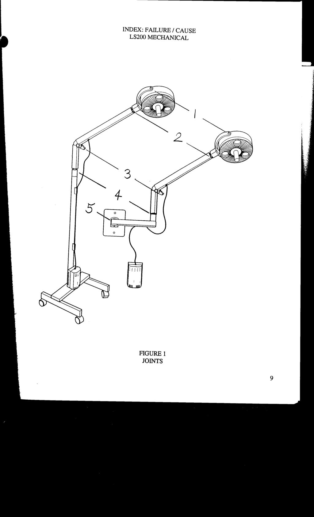
8 INDEX: FAILURE / CAUSE LS200 MECHANICAL D E F I N I T I O N S To simplify text, numbers are used for the names of the joints on the LS200. See figure 1 on page 9. This page of information is for referencing the joints on the LS200 and giving a general description of required adjustments. This page is not service instructions. JOINT NUMBER: DESCRIPTION: Yoke/Housing joint... The crescent shaped part is the yoke. It holds the (# 1 joint) lamp housing. This is a technician adjustable friction joint. Adjust friction to keep lamp housing in position when moved. Tighten/loosen lamp housing 15/16" nut on pivot bolt. (Secure this nut with Loctite #242, M30338.) REMOVE flakes of Loctite which may be in lamp housing. This is the only joint that is lubricated (Dow Corning #7 release compound, M11175) Yoke-arm joint... The yoke is attached to the upper (long) (# 2 joint) arm at the yoke-arm joint # 2. (User can adjust this friction joint by tightening or loosening slotted set screw in arm near joint. This set screw is secured with Loctite #222, M30375.) To replace components of joint # 2, remove short arm. (See sect. I.) Arm joint... The two arm sections are joined at the adjustable (# 3 joint) arm joint. (User can adjust this friction joint by tightening or loosening the black knob.) To replace or repair it, you must remove the lower arm and release spring tension. (See sect.j.) Universal connector... The lower (short) arm attaches to the mounting (# 4 joint) option (pole or wall mount) at the universal connector joint. (User can adjust this friction joint by tightening or loosening the slotted set screw in the arm near this joint. Do not use Loctite on this set screw.) Mount arm joint... The mount arm attaches to the wall mount bracket (# 5 joint) at the mount arm joint. This joint is not adjustable. Disassembled by removing 3 cap screws underneath wall mount bracket. 8
9
10 INDEX: FAILURE / CAUSE LS200 MECHANICAL COMPLAINT / (CONDITION): CAUSE / CORRECTIVE ACTION: Joints are stiff. Excessive resistance to movement at below listed joint(s): #1, 2, 3, 4, 5... foreign matter in joint. DISASSEMBLE, CLEAN, REASSEMBLE, ADJUST. #2, 4... set screw too tight for #2, #4. LOOSEN and ADJUST per instructions in owners manual. #3... arm adjustment knob is too tight. LOOSEN to RESTORE desired holding. #1... pivot nuts too tight. LOOSEN nuts. LS200 does not maintain position: Generally... intended joint friction (other than joint #1 which is supposed to be lubricated) possibly compromised by lubrication. DISASSEMBLE, CLEAN REPLACE brake washers in affected joints and components of joint #3. DO NOT LUBRICATE joints. Only joint #1 requires lubrication with Dow Corning #7 release compound, Welch Allyn M# set screw at #2 is loose or missing. TIGHTEN / REPLACE.... set screw at #4 is loose or missing. TIGHTEN / REPLACE. at #5 joint... wall bracket is not mounted per instructions. CHECK with a level. REMOUNT within 2 degrees of level per instructions in owners manual.... cap head screws are loose or missing. Unit sways or wobbles:... mounting option attachment screw is loose or Entire arm and light head missing. INSTALL screw and TIGHTEN. wobbles.... wall bracket option is not secure. ATTACH to wall (these are customer items) at stud with approved screws only.... joint #3 knob too loose. TIGHTEN.... pole is loose on mobile stand. REASSEMBLE according to instructions. ALIGN the small metal post in the stand with the hole in the pole. 10
11 INDEX: FAILURE / CAUSE LS200 MECHANICAL COMPLAINT / (CONDITION): CAUSE / CORRECTIVE ACTION: Light head wobbles.... clear plastic cover on front of light head is not put on properly. REFER to lamp replacement instructions to VERIFY that plastic cover tabs are aligned with those on the white plastic light housing. REMOVE and RE-INSTALL clear plastic cover. Power supply wobbles.... power supply attachment points are not secure. TIGHTEN this connection by PUSHING the power supply housing down onto the mounting screws as far as it will go. Mobile stand is difficult... casters are locked. UNLOCK casters when moving unit. to move.... wheel(s) are bound up with foreign material such as string. CLEAR obstruction. LS200 is noisy... some type of cleaning agent or solvent may have when articulated. gotten into joint(s). ALLOW it to dry and DO NOT LUBRICATE.... foreign material has built up in the joint. WIPE material out of joints.... the heat shrink tubing over the spring is not in place. REPOSITION to eliminate sound. LS200 makes clicking sound... strap attached to spring is interfering with mandrel when upper arm is raised assembly. Replace strap and any other worn parts in and/or lowered joint #3. REASSEMBLE according to instructions in section K. END LS200 MECHANICAL TROUBLESHOOTING T E C H N I C I A N N O T E S : 11
12 INDEX: REMOVAL AND REPLACEMENT (R & R) PROCEDURES CAUTION : DISCONNECT LS200 FROM A.C. POWER SOURCE BEFORE SERVICING TO AVOID ELECTRICAL SHOCK HAZARD Component: Page: A Bezel assembly B Halogen lamps C Fuses D IEC connector E Power switch F Transformer G Lamp holder H Lamp housing I Yoke J Joint #3 (Main hinge) K Cable L. Joint #4 (Universal connector) M. Mobile stand N. Wall mount T E C H N I C I A N N O T E S : 12
13 CAUTION: DISCONNECT LS200 FROM POWER SOURCE BEFORE SERVICING. A BEZEL ASSEMBLY (R & R) PN CAUTION: ALLOW HOT LAMPS TO COOL FOR 20 MINUTES BEFORE REMOVING BEZEL. A A A A 1. UNPLUG LS200 AND REMOVE HANDLE. (ALSO REFER TO OPERATING INSTRUCTIONS PN ML.) REMOVE POWER CORD FROM A.C. POWER SOURCE. LAY LS200 DOWN WITH HANDLE FACING UP. UNSCREW THE HANDLE COUNTER CLOCKWISE. REMOVE HANDLE. UNSCREW THE TETHER RETAINING NUT AND REMOVE THE TETHER. 2. REMOVE BEZEL. SLIDE THE BEZEL OFF OF THE THREADED ROD. 3. REPLACE BEZEL. INSPECT LAMPS, REFLECTORS, SHROUD, BEZEL, AND GLASS FOR SMUDGES, AND DUST. CLEAN BEFORE REASSEMBLING. DO NOT USE SOLVENTS TO CLEAN BEZEL. PUT BEZEL OVER LIGHT HOUSING WITH THREE TABS OVER THREE RECESSES IN THE LAMP HOUSING. ALIGN TABS ON BEZEL WITH TABS ON LAMP HOUSING. PLACE THE TETHER ONTO THE THREADED ROD OF THE CENTRAL BRACE. THREAD THE NUT ONTO THE THREADED ROD AND TIGHTEN HAND TIGHT. THREAD THE HANDLE ONTO THE THREADED ROD UNTIL IT CONTACTS THE BEZEL. TIGHTEN THE HANDLE SLIGHTLY UNTIL THE BEZEL IS FIRMLY IN PLACE. 4. VERIFY REPAIR. PLUG LS200 INTO MAINS AND TURN SWITCH TO ON POSITION. ALL THREE LAMPS SHOULD BE LIT. TURN OFF. ALL LAMPS MUST TURN OFF. T E C H N I C I A N N O T E S : 13
14 CAUTION: DISCONNECT LS200 FROM POWER SOURCE BEFORE SERVICING. B HALOGEN LAMP REMOVAL AND REPLACEMENT (R & R) PN (OSRAM # 44860sp or 44860nsp, [ 12V/20W/12 degree spread ]) D O N O T T O U C H H O T L A M P! WARNING: ALLOW LAMP TO COOL OFF FOR AT LEAST 20 MINUTES BEFORE TOUCHING LAMP OR SURROUNDING METAL PARTS. NOTE:REFER TO LAMP CHANGING DIAGRAMS IN OWNERS MANUAL #44118ML. B 1. UNPLUG LS200 AND REMOVE BEZEL. REMOVE POWER CORD FROM A.C. POWER SOURCE. TURN THE UNIT FOR EASY ACCESS TO THE HANDLE AND UNSCREW HANDLE COUNTER CLOCKWISE. LET THE BEZEL SWING AWAY TO EXPOSE LAMPS AND LAMP SOCKETS. THE BEZEL WILL BE SUSPENDED BY THE TETHER. D O N O T T O U C H H O T L A M P O R M E T A L P A R T S N E A R L A M P S! B 2. REMOVE LAMP. AFTER A COOLING DOWN PERIOD OF AT LEAST 20 MINUTES, LOCATE AND PULL THE LAMP HOLDING LEVER TO RAISE THE BASE OF THE LAMP OUT OF ENGAGEMENT WITH THE LAMP SOCKET. PULL THE LAMP HOLDING LEVER TOWARD THE BACK OF THE UNIT UNTIL LEVER IS ALMOST VERTICAL. REMOVE THE EXPIRED LAMP AND RETURN THE LEVER TO ITS FORMER POSITION. CAUTION: WEAR A PROTECTIVE GLOVE WHEN REMOVING FRACTURED LAMPS. REMOVE BROKEN LAMP FRAGMENTS FROM THE LAMP HOUSING. B 3. REPLACE WITH NEW LAMP PN RETURN THE LAMP HOLDING LEVER TO ITS ORIGINAL POSITION. NOTE: HOLD THE LAMP ON THE OUTSIDE SURFACES ONLY. FINGER GREASE OR OTHER CONTAMINANTS WILL DARKEN THE QUARTZ ENVELOPE CAUSING DISCOLORATION AND PREMATURE FAILURE OF THE REPLACEMENT LAMP. VERIFY PROPER ALIGNMENT OF PINS IN LAMP SOCKET. PRESS DOWN INTO FULL ENGAGEMENT WITH LAMP SOCKET. LAMP WILL SNAP INTO PLACE. B 4. INSTALL BEZEL. ALIGN THE TABS ON THE BEZEL WITH THE TABS ON THE LAMP HOUSING AND MAKE SURE THAT THE THREE CLEAR WINDOWS IN THE BEZEL LINE UP WITH LAMPS. WHILE HOLDING BEZEL IN PLACE WITH ONE HAND, SCREW THE HANDLE ONTO THE THREADED SHAFT. TIGHTEN THE HANDLE UNTIL IT IS FIRMLY IN PLACE. B 5. TEST TO VERIFY SAFE OPERATION. CONNECT TO POWER SOURCE. PLACE THE POWER SWITCH IN THE ON POSITION. ALLOW NEW LAMPS TO OPERATE FOR FIVE MINUTES TO BURN IN. 14
15 CAUTION: DISCONNECT LS200 FROM POWER SOURCE BEFORE SERVICING. C FUSES (TWO) R & R. DOMESTIC: 1A,250V PN INTERNATIONAL: 0.5A,250V PN CAUTION: IF AN LS200 HAS BEEN RETURNED FOR FUSE REPLACEMENT, DO NOT JUST REPLACE FUSES AND PLUG IN TO TEST. INSTEAD: 1. LOCATE AND ELIMINATE THE SHORT CIRCUIT BY TESTING TRANSFORMER OR WIRING. DETERMINE THE CAUSE OF THE PROBLEM IF POSSIBLE, ex.: LINE SURGE. WHAT COMPONENT(S), IF ANY, WERE DAMAGED? 2. RESTORE THE CIRCUIT TO SPECIFICATIONS BEFORE REPLACING FUSE AND ENERGIZING. * LOCATE AND ELIMINATE SHORT CIRCUITS (LINE TO LINE OR LINE TO GROUND ) BEFORE CONNECTING LS200 TO MAINS. INSPECT WIRE INSULATION AND COMPONENTS FOR BURN AND SMOKE MARKS. REPLACE ALL DAMAGED COMPONENTS TO RESTORE CIRCUIT TO SPECIFICATIONS. INSPECT TRANSFORMER ASSEMBLY FIRST. C 1. REMOVE FUSE DRAWER. DISCONNECT LS200 FROM POWER SOURCE. REMOVE POWER CORD FROM UNIT POWER CORD RECEPTACLE. INSERT THE FLAT BLADE OF A SMALL SCREWDRIVER (1/8") INTO SLOTS ON SIDES OF THE FUSE DRAWER. PRY BOTH LATCHES AND SLIDE THE FUSE DRAWER OUT OF THE RECEPTACLE. C 2. REMOVE FUSES FROM FUSE DRAWER. PULL BOTH FUSES FROM FUSE DRAWER AND VERIFY THAT ONE OR BOTH ARE ELECTRICALLY OPEN (BLOWN). NOTE THE FUSE RATING. THIS IS IMPORTANT SINCE THE FUSES MAY HAVE BLOWN BECAUSE THEIR AMP RATING WAS BELOW THE REQUIRED AMP RATING FOR THIS PRODUCT. THUS, THE FUSES WERE AT FAULT, NOT THE LS200 CIRCUITS. FUSES OF THE PROPER RATING CAN BE INSTALLED AND THE LAMP TURNED ON FOR A FUNCTIONAL CHECK. FUSES CAN BE CHECKED VISUALLY FOR OPEN FILAMENT. CONTINUITY CAN BE CHECKED WITH AN ANALOG OR DIGITAL VOLT OHM METER D.V.O.M.. OPEN (BLOWN) FUSES HAVE INFINITE RESISTANCE ( OL SYMBOL INDICATES OPEN LEADS FOR MANY DIGITAL VOLT-OHM METERS). C 3. INSTALL NEW FUSES IN FUSE DRAWER. INSERT TWO FUSES IN THE RECESSES IN THE FUSE DRAWER. REPLACE BOTH FUSES, EVEN WHEN ONE IS NOT BLOWN (MELTED THROUGH.) ALIGN THE TAB ON THE BOTTOM OF THE FUSE DRAWER WITH THE SLOT IN THE POWER CORD RECEPTACLE. EVENLY INSERT THE FUSE DRAWER INTO HOUSING UNTIL ITS DETENTS LATCH. C 4. TEST TO VERIFY SAFE OPERATION. CONNECT LS200 TO POWER SOURCE AND VERIFY THAT ALL THREE LAMPS ARE LIT. CONDUCT HI-POT TEST PER A
16 CAUTION: DISCONNECT LS200 FROM POWER SOURCE BEFORE SERVICING. D D D D D D IEC CONNECTOR R & R 1. REMOVE BACK HOUSING. DISCONNECT LS200 FROM MAINS. IF MOUNTED ON MOBILE STAND, DETACH TRANSFORMER ASSEMBLY FROM POLE. REMOVE FOUR SCREWS AND REMOVE BACK HOUSING. 2. REMOVE IEC CONNECTOR. DISCONNECT THREE WIRES FROM THE TERMINALS ON THE BACK OF THE IEC CONNECTOR (POWER RECEPTACLE). LIFT IEC CONNECTOR OUT OF THE FRONT HOUSING. RE-USE THE OLD FUSE TRAY IF IT IS NOT DAMAGED. NEW FUSES OF THE CORRECT RATING SHOULD BE USED. 3. INSTALL REPLACEMENT IEC CONNECTOR. ALIGN REPLACEMENT POWER RECEPTACLE WITH THE GROUND (CENTER) TERMINAL AT THE BOTTOM OF THE HOLE IN THE CHASSIS. PRESS RECEPTACLE INTO HOUSING CUTOUT. CONNECT WIRES PER ASSEMBLY DRAWING. CONNECT THE BLACK WIRES TO THE IEC CONNECTOR AT FI AND F2. THE CENTER TERMINAL IS THE GROUND TERMINAL...CONNECT THE GREEN WITH YELLOW STRIPE (GROUND WIRE) TO THE GROUND TERMINAL. 4. ATTACH BACK HOUSING OF POWER SOURCE. MAKE SURE THE STRAIN RELIEF AND IEC CONNECTOR ARE IN THE NOTCHES IN THE FRONT HOUSING. BE CAREFUL NOT TO PINCH WIRES ON SECONDARY SIDE WHILE CLOSING HOUSING. POSITION THE COVER ONTO THE POWER SUPPLY HOUSING AND FASTEN IT WITH FOUR SCREWS. 5. TEST TO VERIFY SAFE OPERATION. CONNECT LS200 TO POWER SOURCE AND VERIFY THAT ALL THREE LAMPS ARE LIT. CONDUCT HI-POT TEST PER A T E C H N I C I A N N O T E S : 16
17 CAUTION: DISCONNECT LS200 FROM POWER SOURCE BEFORE SERVICING. E NOTE: E E E E POWER SWITCH R & R IT IS NOT NECESSARY TO DISASSEMBLE THE LAMP HOUSING TO REPLACE THE SWITCH. 1. REMOVE SWITCH. APPLY A SMALL PIECE OF MASKING TAPE TO THE LAMP HOUSING ALONG THE EDGES OF THE SWITCH TO PROTECT THE SURFACE FINISH OF HOUSING DURING SWITCH REMOVAL. PULL THE OLD SWITCH OUT OF THE LIGHT HOUSING BY PRYING UPWARDS AT THE END OF THE SWITCH WITH A THIN EDGE SUCH AS A PUTTY KNIFE. 2. DISCONNECT WIRES FROM SWITCH. UNPLUG ALL FOUR (4) WIRES FROM THE BOTTOM OF THE SWITCH. 3. INSTALL NEW SWITCH. ATTACH WIRES AND PRESS SWITCH INTO LAMP HOUSING, MAKING SURE THAT THE LAMP SYMBOL ON THE TOP OF THE SWITCH IS TOWARDS THE WORD WELCH OF THE WELCH ALLYN NAME ON THE FRONT OF THE HOUSING. THESE WIRES CONDUCT A.C. CURRENT AND AS SUCH MAY BE ATTACHED TO THE SWITCH IN EITHER POSITION. REFER TO ASSEMBLY DRAWING NO VERIFY REPAIR. CONNECT LS200 TO POWER SOURCE AND OPERATE THE SWITCH APPROXIMATELY 5 TIMES TO DETERMINE THAT THE SWITCH IS OPERATING PROPERLY. VERIFY THAT ALL THREE LAMPS LIGHT. T E C H N I C I A N N O T E S : 17
18 CAUTION: DISCONNECT LS200 FROM POWER SOURCE BEFORE SERVICING. F TRANSFORMER ASSEMBLY R & R. NOTE: TO CHECK FOR DEFECTIVE TRANSFORMER, MEASURE:input (120V) 60HZ AND OUTPUT (12.6 VAC,+/-.2 Amps.) SEE DWG# LOW OUTPUT INDICATES A DEFECTIVE TRANSFORMER. HOWEVER, EVEN A GOOD TRANSFORMER WILL PRODUCE LOW OUTPUT IF INPUT VOLTAGE IS BELOW REQUIREMENTS. MEASURE BOTH. LIGHT INTENSITY IS PROPORTIONAL TO CURRENT PASSING THROUGH THE LAMP FILAMENT. F F F F F F 1. REMOVE BACK HOUSING. DISCONNECT LS200 FROM MAINS. REMOVE TRANSFORMER ASSEMBLY FROM POLE OF MOBILE STAND IF SO EQUIPPED. REMOVE FOUR SCREWS AND REMOVE BACK HOUSING. 2. REMOVE OLD TRANSFORMER. DISCONNECT FIVE (5) TRANSFORMER WIRES FROM POWER CONNECTOR AND SECONDARY CABLE (GRAY CORD). REMOVE TRANSFORMER STRAPS BY UNSCREWING FOUR PHILLIPS HEAD SCREWS. LIFT TRANSFORMER OUT OF FRONT HOUSING. 3. INSTALL REPLACEMENT TRANSFORMER. ALIGN TRANSFORMER (WITH WIRES DOWN ) WITH THREE (3) PRIMARY WIRES TOWARDS THE POWER CONNECTOR. THESE WIRES MUST PASS BETWEEN THE RIBS OF THE TRANSFORMER SUPPORT. ALIGN STRAPS SO THAT HOLES IN STRAPS MATCH WITH HOLES IN TRANSFORMER. SECURE THE TRANSFORMER WITH TWO STRAPS AS SHOWN ON ASSEMBLY DRAWING #441019, AND FOUR STRAP- HOLDING SCREWS. TIGHTEN SCREWS. 4. RESTORE ELECTRICAL CONNECTIONS. CONNECT SPADE CONNECTORS OF TRANSFORMER PRIMARY WIRES TO TERMINALS OF POWER CONNECTOR AS SHOWN IN ASSEMBLY DRAWING. BUNDLE THE THREE LINE SIDE WIRES TOGETHER WITH A WIRE TIE. CONNECT SECONDARY TRANSFORMER WIRES TO CABLE. 5. ATTACH BACK HOUSING OF POWER SOURCE. MAKE SURE THE STRAIN RELIEF AND IEC CONNECTOR ARE IN PLACE. PLACE THE COVER ONTO THE POWER SUPPLY HOUSING BEING CAREFUL NOT TO PINCH WIRES BETWEEN THE CASES. FASTEN WITH FOUR (4) SCREWS. 6. TEST TO VERIFY SAFE OPERATION. CONNECT LS200 TO POWER SOURCE AND VERIFY THAT ALL THREE LAMPS ARE LIT. CONDUCT HI-POT TEST PER A T E C H N I C I A N N O T E S : 18
19 CAUTION: DISCONNECT LS200 FROM POWER SOURCE BEFORE SERVICING. G LAMP HOLDER R & R G 1. REMOVE BEZEL. (ALSO REFER TO PG.8 OPERATING INSTRUCTIONS PN ML) PUT POWER SWITCH IN OFF POSITION AND REMOVE POWER CORD CONNECTOR FROM A.C. POWER SOURCE. LAY UNIT DOWN WITH HANDLE UP. UNSCREW HANDLE COUNTER CLOCKWISE. REMOVE NUT, TETHER AND BEZEL ASSEMBLY. DANGER! D O N O T T O U C H H O T L A M P S O R H O T L A M P H O L D E R S! (GLASS AND METAL COMPONENTS RETAIN HEAT EVEN AFTER LAMPS ARE OFF SEVERAL MINUTES.) G G G G G 2. REMOVE COOL LAMP(S). AFTER A COOLING DOWN PERIOD OF AT LEAST 20 MINUTES, LOCATE AND PULL THE LAMP HOLDING LEVER TO RAISE THE BASE OF THE LAMP OUT OF ENGAGEMENT WITH THE LAMP SOCKET. PULL THE LAMP HOLDING LEVER TOWARD THE BACK OF THE UNIT UNTIL LEVER IS ALMOST VERTICAL. REMOVE EXPIRED LAMP. 3. REMOVE OLD LAMP HOLDER FROM LAMP HOLDER. UNSCREW THREE SCREWS. CUT THE LAMP HOLDER WIRES AS CLOSE TO THE LAMP HOLDER AS POSSIBLE. LIFT OLD LAMP HOLDER OUT OF LAMP HOUSING. 4. ATTACH REPLACEMENT LAMP HOLDER TO LAMP HOUSING. CONNECT REPLACEMENT LAMP HOLDER WIRES TO OLD WIRES USING BUTT SPLICES PN KEEPING WIRES OUT FROM UNDER THE LAMP HOLDER, POSITION LAMP HOLDER OVER THREE THREADED BOSSES IN LAMP HOUSING. MAKE SURE THAT THE WIRES DO NOT INTERFERE WITH THE LAMP CHANGING LEVERS. INSERT AND TIGHTEN THREE SCREWS. INSTALL LAMP. 5. INSTALL BEZEL ASSEMBLY. FOLLOW INSTRUCTIONS IN SECTION B-4 PG 14 TO ATTACH THE BEZEL ASSEMBLY TO THE LS TEST TO VERIFY SAFE OPERATION. CONNECT TO A.C. POWER SOURCE AND ILLUMINATE LAMP. LET THE UNIT STAY ON FOR FIVE MINUTES TO VERIFY PROPER OPERATION. T E C H N I C I A N N O T E S : 19
20 CAUTION: DISCONNECT LS200 FROM POWER SOURCE BEFORE SERVICING. H LAMP HOUSING PN R & R. H 1. REMOVE BEZEL. UNPLUG LS200 AND REMOVE HANDLE. (ALSO REFER TO OPERATING INSTRUCTIONS PN ML.) REMOVE POWER CORD FROM A.C. POWER SOURCE. LAY LS200 DOWN WITH HANDLE FACING UP. UNSCREW THE HANDLE COUNTER-CLOCKWISE. REMOVE HANDLE. UNSCREW THE TETHER RETAINING NUT AND REMOVE THE TETHER. REMOVE BEZEL. DANGER! D O N O T T O U C H H O T L A M P S O R H O T L A M P H O L D E R S! GLASS AND METAL COMPONENTS RETAIN HEAT EVEN AFTER THE LAMPS HAVE BEEN TURNED OFF SEVERAL MINUTES. H H H H 2. REMOVE COOL LAMPS. AFTER A COOLING DOWN PERIOD OF AT LEAST 20 MINUTES, LOCATE AND PULL THE LAMP HOLDING LEVER TO RAISE THE BASE OF THE LAMP OUT OF ENGAGEMENT WITH THE LAMP SOCKET. PULL THE LAMP HOLDING LEVER TOWARD THE BACK OF THE UNIT UNTIL LEVER IS ALMOST VERTICAL. REMOVE EXPIRED LAMP. 3. UNSCREW TWO LAMP HOLDERS NEAR PIVOT BOLTS. (TOP HOLDERS) MARK LAMP HOLDERS (REPLACE IN SAME POSITIONS.) REMOVE THREE SCREWS ON EACH OF THE TWO LAMP HOLDERS ADJACENT TO THE POWER SWITCH. THESE 2 LAMP HOLDERS WILL REMAIN IN THE LAMP HOUSING, ATTACHED TO THE WIRES, UNTIL THE LAST LAMP HOLDER AT THE BOTTOM OF THE LAMP HOUSING (BOTTOM LAMP HOLDER) IS REMOVED. DO NOT CUT ANY OF THE LAMP HOLDER WIRES OR SPLICES. UNSCREW BOTH OF THE 4-WAY CONNECTORS. 4. REMOVE SWITCH. UNPLUG ALL FOUR (4) WIRES FROM THE BOTTOM OF THE SWITCH AND CUT OFF THE SPADE CONNECTORS ON THE BLACK AND WHITE WIRES ONLY. CUT RIGHT AT THE CONNECTOR. THESE TWO WIRES ARE THE 12 VOLT SUPPLY FOR THE LAMPS. SQUEEZE DETENTS TOGETHER ON THE BACK OF THE SWITCH AND REMOVE SWITCH FROM LAMP HOUSING. REMOVE FOAM RUBBER INSERT FROM THE YOKE. INSERT A SMALL SCREWDRIVER IN THE YOKE RECESS NEAR THE PIVOT. PUSH THE WA LOGO PLATE OUT OF THE PIVOT RECESS. PUSH THE BLACK AND WHITE POWER WIRES OUT OF THE LAMP HOUSING THROUGH PIVOT BOLTS. 5. REMOVE YOKE PIVOT BOLTS AND HARDWARE. UNSCREW 15/16" NUTS FROM YOKE PIVOT BOLTS. (NUTS HAVE LOCTITE #242 ON THEM.) REMOVE SPACER AND WAVE WASHER. ALIGN FLAT OF THE PIVOT BOLT WITH THE FLAT IN THE HOLE ( D HOLE) IN THE BRACKET. PRESS BOLTS OUT OF LAMP HOUSING. REMOVE LAMP HOUSING FROM YOKE. 20
21 CAUTION: DISCONNECT LS200 FROM POWER SOURCE BEFORE SERVICING. H H H H H LAMP HOUSING ASSEMBLY R & R CONTINUED REMOVE CENTRAL BRACE. UNSCREW FOUR (4) PHILLIPS HEAD SCREWS AND REMOVE THE BRACKET FROM THE LAMP HOUSING. REMOVE LAST (BOTTOM) LAMP HOLDER. 7. ATTACH EXISTING LAMP HOLDERS AND CENTRAL BRACE. ATTACH BOTTOM LAMP HOLDER WITH 3 PHILLIPS HEAD SCREWS. MAKE SURE THAT WIRES ARE ROUTED ACCORDING TO ABOVE DRAWING. TEMPORARILY ATTACH REMAINING TWO LAMP HOLDERS WITH ONLY ONE SCREW EACH. ATTACH FOUR-WAY CONNECTORS. ATTACH CENTRAL BRACE WITH FOUR PHILLIPS SCREWS. IF A NEW CENTRAL BRACE IS BEING INSTALLED ALONG WITH THE NEW LAMP HOUSING, ATTACH A NEW WARNING LABEL WITH THE SAME ORIENTATION AS THE ORIGINAL. 8. ATTACH LAMP HOUSING ASSEMBLY TO YOKE. FULLY ENGAGE THE LAMP HOUSING IN THE YOKE. INSERT PIVOT BOLTS THROUGH YOKE WITH FLAT SIDE OF BOLT ALIGNED WITH FLAT OF CENTRAL BRACE. SECURE THE LAMP HOUSING WITH THE FOLLOWING ITEMS ASSEMBLED IN SEQUENCE AS LISTED (FOR EACH PIVOT BOLT): 1ST... INSTALL ONE (1) SPACER (GRAY MATERIAL WASHER), 2ND... INSTALL ONE (1) WAVE WASHER, 3RD... APPLY LOCTITE 242, WA M#30338 TO ONE HALF OF 5 15/16" NUT THREADS, 4TH... ONE 15/16 NUT. TIGHTEN NUTS EQUALLY, UNTIL ONE THREAD IS VISIBLE ON THE BOLT. ROTATE THE LAMP HOUSING ASSEMBLY BY PULLING WITH A FORCE GAUGE AT THE TOP OF THE CENTER BOLT. ADJUST NUT TIGHTNESS UNTIL A READING OF BETWEEN 1.0 TO 3.0 LBS IS OBTAINED. 9. INSTALL THE LAMP HOLDERS AND RESTORE CONNECTIONS. FASTEN LAMP HOLDERS TO LAMP HOUSING USING THREE #6 PHILLIPS HEAD SCREWS. FEED WIRES THROUGH THE YOKE CHANNEL, PIVOT BOLTS, AND UNDER THE CENTRAL BRACE. GENTLY PULL ON THE BLACK AND WHITE CABLE WIRES AS THEY ENTER LAMP HOUSING TO REMOVE ANY SLACK THAT MIGHT BE PRESENT WHERE THEY PASS THROUGH THE HOLLOW CRESCENT OF THE YOKE. WHEN SLACK IS REMOVED, PRESS WIRES INTO NOTCHES IN THE CRESCENT OR THE FOAM INSERT WILL NOT FIT PROPERLY. INSTALL FOAM IN YOKE. ATTACH WELCH ALLYN LOGOS IN RECESSES OVER PIVOT BOLTS AND ALIGNED WITH PARTING LINE IN YOKE. H 10. INSTALL SWITCH, LAMPS AND BEZEL. CRIMP TWO FEMALE QUICK CONNECTS PN ONTO THE BLACK AND WHITE POWER WIRES. PRESS SWITCH INTO CUTOUT OF LAMP HOUSING. ATTACH WIRES TO SWITCH AND INSTALL WIRE TIES PER DWG# INSTALL LAMPS AND BEZEL(SEE B-3 THROUGH B-4.) 21
22 I I I I I CAUTION: DISCONNECT LS200 FROM POWER BEFORE SERVICING. YOKE R & R 1. REMOVE LAMP HOUSING. REFER TO SECTION H-1, H-4, AND H-5 ON PAGE 20, BUT LEAVE TWO RED WIRES ATTACHED TO THE SWITCH SINCE IT IS NOT BEING REMOVED. 2. REMOVE LOWER ARM. REMOVE TWO FLAT HEAD PHILLIPS SCREWS NEAREST JOINT #3 (ADJUSTABLE JOINT), AND SLIDE LOWER ARM OFF OF HINGE BRACKET. 3. REMOVE STRAP FROM HINGE BRACKET. UNSCREW 3/8" NUT FROM STUD. USE SLIP JOINT PLIERS TO PULL AND LIFT STRAP FROM STUD. (THIS WILL RELIEVE TENSION ON 2 YOKE SCREWS AND PERMITS DISASSEMBLY OF SPRING BRACKET FROM YOKE STUD.) 4. REMOVE STRAIN RELIEF. COMPRESS STRAIN RELIEF WITH HEYCO TOOL AND REMOVE STRAIN RELIEF FROM LONG ARM. I 5. UNSCREW YOKE SET SCREW AT JOINT #2. USE FLAT BLADE SCREWDRIVER TO UNSCREW YOKE SET SCREW. I 6. REMOVE YOKE FROM JOINT #2. UNSCREW TWO FLAT HEAD PHILLIPS SCREWS FROM UPPER ARM AT YOKE JOINT. WHILE FEEDING CABLE BACK OUT OF YOKE, PULL YOKE OUT OF JOINT #2. WHEN CONNECTOR PLATE IS ACCESSIBLE, REMOVE IT FROM CONNECTOR BLOCK/YOKE STUD ASSEMBLY. TWO FLAT SPRINGS, BRAKE MATERIAL, AND NYLINERS WILL COME OUT OF CONNECTOR BLOCK. REMOVE END CAPS. I I I 7. REMOVE CABLE FROM YOKE. GENTLY PULL WIRES OUT OF YOKE. DISCARD YOKE. 8. ASSEMBLE CONNECTOR BLOCK TO END OF NEW YOKE. SNAP ONE OF THE END CAPS ONTO THE YOKE. PLACE A SECOND END CAP ONTO STUD FACING OTHER END CAP. INSERT NYLINERS TO EACH END OF CONNECTOR BLOCK BORE. FEED THE BLACK/ WHITE WIRES THROUGH STUD INTO YOKE. PLACE THE STUD PORTION OF THE YOKE INTO THE CONNECTOR BLOCK. 9. PLACE THE STRAP/SPRING CONNECTOR PLATE ASSEMBLY ONTO THE CONNECTOR BLOCK/YOKE ASSEMBLY. PLACE THE BRAKE MATERIAL AND TWO FLAT SPRINGS (CURVED SIDE UP) INTO THE OPENING IN THE CONNECTOR BLOCK. POSITION THE CONNECTOR PLATE OVER THE CONNECTOR BLOCK/YOKE STUD ASSEMBLY WITH THE ROTATIONAL STOP OF THE STUD ENGAGED WITH THE CONNECTOR PLATE. 22
23 CAUTION: DISCONNECT LS200 FROM POWER SOURCE BEFORE SERVICING. I YOKE R & R, CONTINUED... I 10. SLIDE CONNECTOR BLOCK, YOKE STUD, CONNECTOR PLATE, INTO THE UPPER ARM TUBE. ALIGN THE KEY EXTRUSION OF THE INTERIOR OF THE UPPER ARM WITH THE KEY WAY OF THE CONNECTOR BLOCK. MAKE SURE THE END OF THE GRAY CABLE IS PULLED ALL THE WAY INTO THE YOKE SO THAT THE CABLE INSULATION IS VISIBLE WHERE THE SHAFT JOINS THE CRESCENT. I 11. SECURE CONNECTOR BLOCK TO LONG ARM TUBE WITH TWO SCREWS. FIRST INSTALL THE PHILLIPS SCREW CLOSEST TO THE YOKE AND TIGHTEN IT TO A MINIMUM OF 15 INCH LBS. THEN INSTALL AND TIGHTEN THE SECOND AND LAST SCREW AND TIGHTEN IT TO THE SAME TORQUE. THESE YOKE SCREWS AT JOINT #2 MUST BE TIGHTENED BEFORE TENSIONING THE SPRING STRAP TO PREVENT SCREW HOLES FROM BECOMING MISALIGNED BECAUSE OF SPRING TENSION. DO NOT INSTALL SET SCREW AT THIS TIME. I 12. INSTALL LOWER ARM / UNIVERSAL JOINT ASSEMBLY. ATTACH STRAP TO STUD USING TOOL T INSTALL AND TIGHTEN NUT. C A U T I O N!! MAKE SURE YOUR FINGERS ARE AWAY FROM THE HINGE AREA BEFORE PRESSING THE SHORT ARM ALL THE WAY ONTO THE HINGE BRACKET. THERE IS THE RISK OF PINCHING FINGERS IF THE ARM IS PRESSED ON WHILE HOLDING THE MANDREL DOWN. THE MANDREL DOES NOT NEED TO BE HELD DOWN. SLIDE THE LOWER ARM (SHORT ARM) ONTO THE HINGE BRACKET UNTIL IT IS APPROXIMATELY 1/4" AWAY FROM CONTACTING THE MANDREL. HOLD THE LONG ARM DOWN AND LIFT THE SHORT ARM UP APPROXIMATELY 45 DEGREES. WHILE HOLDING IT IN THAT POSITION, PRESS THE MANDREL DOWN AND RELEASE IT. IT WILL STAY IN POSITION WITHOUT HOLDING IT SO THAT IT CAN FIT INSIDE OF THE SHORT ARM. REMOVE YOUR FINGER FROM THE MANDREL AREA AND SLIDE THE SHORT ARM ON AS FAR AS IT WILL GO. INSTALL AND TIGHTEN TWO SCREWS. I 13. INSTALL STRAIN RELIEF. CAREFULLY REMOVE ANY CABLE SLACK THAT MAY BE PRESENT IN THE LONG ARM. GENTLY PULL THE CABLE AT THE STRAIN RELIEF HOLE WHILE HOLDING ON TO THE BLACK AND WHITE WIRES AT THE YOKE. DON T LET THESE SLIP BACK DOWN INTO THE HOLE IN THE STUD. INSTALL STRAIN RELIEF USING STRAIN RELIEF TOOL. 23
24 I CAUTION: DISCONNECT LS200 FROM POWER SOURCE BEFORE SERVICING. YOKE R & R, CONTINUED... I 14. ATTACH LAMP HOUSING ASSEMBLY TO YOKE. APPLY LUBRICANT DOW CORNING #7 RELEASE COMPOUND (M11175) TO THE CONTACT SURFACES BETWEEN THE YOKE AND LAMP HOUSING. FULLY ENGAGE THE LAMP HOUSING IN THE YOKE. INSERT PIVOT BOLTS THROUGH YOKE WITH FLAT SIDE OF BOLT ALIGNED WITH FLAT OF CENTRAL BRACE. SECURE THE LAMP HOUSING WITH THE FOLLOWING ITEMS ASSEMBLED IN SEQUENCE AS LISTED (FOR EACH PIVOT BOLT): 1ST...INSTALL ONE (1) SPACER (GRAY WASHER), 2ND... INSTALL ONE (1) WAVE WASHER, 3RD... APPLY LOCTITE 242, WA M#30338 TO ONE HALF OF 5 15/16" NUT THREADS, 4TH... ONE 15/16 NUT. TIGHTEN NUTS EQUALLY, UNTIL ONE THREAD IS VISIBLE ON THE BOLT. ROTATE THE LAMP HOUSING ASSEMBLY BY PULLING WITH A FORCE GAUGE AT THE TOP OF THE CENTER BOLT. ADJUST NUT TIGHTNESS UNTIL A READING OF BETWEEN 1.0 TO 3.0 LBS IS OBTAINED. I 15. INSTALL THE LAMP HOLDERS AND RESTORE CONNECTIONS. FASTEN LAMP HOLDERS TO LAMP HOUSING USING THREE #6 PHILLIPS HEAD SCREWS. FEED WIRES THROUGH THE YOKE CHANNEL, PIVOT BOLTS, AND UNDER THE CENTRAL BRACE. GENTLY PULL ON THE BLACK AND WHITE CABLE WIRES AS THEY ENTER LAMP HOUSING TO REMOVE ANY SLACK THAT MIGHT BE PRESENT WHERE THEY PASS THROUGH THE HOLLOW CRESCENT OF THE YOKE. WHEN SLACK IS REMOVED, PRESS WIRES INTO NOTCHES IN THE CRESCENT OR THE FOAM INSERT WILL NOT FIT PROPERLY. INSTALL FOAM IN YOKE. ATTACH WELCH ALLYN LOGOS IN RECESSES OVER PIVOT BOLTS AND ALIGNED WITH PARTING LINE IN YOKE. I 16. INSTALL BEZEL. CRIMP TWO FEMALE QUICK CONNECTS PN ONTO THE BLACK AND WHITE POWER WIRES. ATTACH WIRES TO SWITCH AND INSTALL WIRE TIES PER DWG# INSTALL LAMPS AND BEZEL (SEE B-3 THROUGH B-4). I 17. INSTALL SET SCREW AND ADJUST JOINT #2 SET SCREW. PLACE ONE DROP OF LOCTITE 222 M#30375 TO SET SCREW AND THREAD INTO HOLE. PLACE UNIT IN UPRIGHT POSITION AND ROTATE JOINT #2 TO THE STOP. VERY SLOWLY, LOOSEN SET SCREW UNTIL THE LIGHT HOUSING ROTATES DOWNWARD. STOP AND TURN THE SCREW CLOCKWISE 1/4 TURN. ROTATE THE LIGHT HOUSING TO THE STOP AND RELEASE. IF THE SET SCREW IS ADJUSTED PROPERLY, THE LIGHT HOUSING WILL STAY IN POSITION WHEN RELEASED. 24
25 CAUTION: DISCONNECT LS200 FROM POWER SOURCE BEFORE SERVICING. I YOKE R & R, CONTINUED... I 18. TEST JOINTS. WITH THE LS200 IN AN UPRIGHT POSITION, CYCLE THE ARM UP AND DOWN THREE TO FIVE TIMES. CHECK FORT AN;Y BINDING OF THE JOINT. WITH THE ARM AT 45 DEGREES, CHECK FOR DROOP. WITH THE ARM ALL THE WAY DOWN AT THE 90 DEGREE POSITION, CHECK FOR SPRINGBACK. TEST TO VERIFY SAFE OPERATION. CONNECT TO A.C. POWER SOURCE AND VERIFY THAT ALL THREE LAMPS ILLUMINATE. T E C H N I C I A N N O T E S : 25
26 CAUTION: DISCONNECT LS200 FROM POWER SOURCE BEFORE SERVICING. J JOINT #3 R & R. J J J J J J J 1. REMOVE LOWER ARM. REMOVE TWO FLAT HEAD PHILLIPS SCREWS NEAREST JOINT #3 (ADJUSTABLE JOINT), AND SLIDE LOWER ARM OFF OF HINGE BRACKET. 2. REMOVE STRAP FROM HINGE BRACKET. UNSCREW NUT FROM STUD. USE SLIP JOINT PLIERS TO PULL AND LIFT STRAP FROM STUD. 3. UNSCREW HINGE FROM UPPER ARM. UNSCREW TWO FLAT HEAD PHILLIPS SCREWS IN UPPER ARM NEAREST HINGE. REMOVE HINGE JOINT FROM UPPER ARM BEING CAREFUL NOT TO CATCH THE END OF THE STRAP ON PARTS OF THE HINGE JOINT. 4. DISASSEMBLE HINGE IF NECESSARY. REMOVE JOINT KNOB AND BOLT. REMOVE THE NON TWIST BRACE (NTB) AND NYLON WASHERS. REMOVE ALL HINGE PARTS. 5. INSTALL NEW HINGE SEGMENTS. PLACE LOCTITE PRIMER #770 (M30391) ONTO JOINT BEARINGS PRIOR TO ASSEMBLY AND ALLOW TO DRY UNTIL A DULL FINISH RETURNS TO PART. APPLY TWO DROPS OF LOCTITE #403 (M30372) TO HINGE BRACKETS ON SURFACE WHERE BEARINGS MATE. ADHERE THE BEARINGS TO THE HINGE BRACKETS. POSITION THE PARTS ON THE BENCH WITH THE OPEN SIDE OF THE HINGE BRACKETS FACING YOU, AND THE HINGE BRACKET WITH THE STUD ON YOUR LEFT HAND SIDE. 6. INSERT PIVOT BOLT. SCREW THE GOAL POST ONTO THE MANDREL. PLACE THE MANDREL, WITH FRICTION WASHER ON BOTTOM, INTO THE CENTER OF THE ASSEMBLY. PLACE THE NON-TWIST-BRACE (NTB) SQUARE CUT-OUT ON TOP, AND ONE NYLON WASHER (ON THE BOTTOM SIDE), OVER THE ENTIRE JOINT ASSEMBLY. THE TAB ON THE NTB SHOULD ENGAGE WITH THE HINGE BRACKET. INSERT A SCREWDRIVER THROUGH ASSEMBLY AND ALIGN PARTS. REMOVE SCREWDRIVER AND INSERT PIVOT BOLT THROUGH ASSEMBLY. ENSURE THAT THE SQUARE ON THE PIVOT BOLT COMPLETELY ENGAGES WITH THE SQUARE OF THE NTB. TIGHTEN KNOB ONTO BOLT. 7. INSTALL JOINT ASSEMBLY. SLIDE JOINT ASSEMBLY INTO THE UPPER ARM WHILE ROUTING STRAP UNDER THE MANDREL. ATTACH THE JOINT TO THE UPPER ARM WITH TWO PHILLIPS SCREWS. 26
27 CAUTION: DISCONNECT LS200 FROM POWER SOURCE BEFORE SERVICING. J J JOINT #3 R & R CONTINUED INSTALL LOWER ARM / UNIVERSAL JOINT ASSEMBLY. ATTACH STRAP TO STUD USING TOOL T INSTALL AND TIGHTEN NUT. C A U T I O N!! MAKE SURE YOUR FINGERS ARE AWAY FROM THE HINGE AREA BEFORE PRESSING THE SHORT ARM ALL THE WAY ONTO THE HINGE BRACKET. THERE IS THE RISK OF PINCHING FINGERS IF THE ARM IS PRESSED ON WHILE HOLDING THE MANDREL DOWN. THE MANDREL DOES NOT NEED TO BE HELD DOWN. SLIDE THE LOWER ARM (SHORT ARM) ONTO THE HINGE BRACKET UNTIL IT IS APPROXIMATELY 1/4" AWAY FROM CONTACTING THE MANDREL. HOLD THE LONG ARM DOWN AND LIFT THE SHORT ARM UP APPROXIMATELY 45 DEGREES. WHILE HOLDING IT IN THAT POSITION, PRESS THE MANDREL DOWN AND RELEASE IT. IT WILL STAY IN POSITION WITHOUT HOLDING IT SO THAT IT CAN FIT INSIDE OF THE SHORT ARM. REMOVE YOUR FINGER FROM THE MANDREL AREA AND SLIDE THE SHORT ARM ON AS FAR AS IT WILL GO. INSTALL AND TIGHTEN TWO SCREWS. J 9. TEST TO VERIFY SAFE AND PROPER OPERATION. WITH THE LS200 IN AN UPRIGHT POSITION, CYCLE THE ARM UP AND DOWN THREE TO FIVE TIMES. CHECK FOR ANY BINDING OF THE JOINT. WITH THE ARM AT 45 DEGREES, CHECK FOR DROOP. WITH THE ARM ALL THE WAY DOWN AT THE 90 DEGREE POSITION, CHECK FOR SPRINGBACK. CONNECT TO A.C. POWER SOURCE AND VERIFY ALL THREE LAMPS ILLUMINATE. T E C H N I C I A N N O T E S : 27
28 CAUTION: DISCONNECT LS200 FROM POWER SOURCE BEFORE SERVICING. K CABLE R & R. K K K K 1. REMOVE JOINT # 3 (MAIN HINGE WITH KNOB). FOLLOW INSTRUCTIONS IN SECTION J-1 THROUGH J-4 ON PG REMOVE BEZEL. FOLLOW INSTRUCTIONS IN SECTION A-1 AND A-2 ON PG DISCONNECT CABLE FROM POWER SOURCE. REMOVE FOUR SCREWS TO OPEN TRANSFORMER HOUSING. DISCONNECT CABLE FROM TRANSFORMER. 4. DISCONNECT CABLE FROM LONG ARM. REMOVE STRAIN RELIEF WITH HEYCO TOOL #29. CUT CONNECTORS FROM BOTH ENDS OF THE CABLE. PULL FOAM OUT OF YOKE AND PULL WIRES OUT OF YOKE. REFER TO SECTION I-5 AND I-6 TO REMOVE YOKE FROM ARM AND TO OBTAIN ACCESS TO THE CABLE. REMOVE CABLE FROM THE ASSEMBLY BY PULLING FROM THE STRAIN RELIEF HOLE. K 5. INSTALL NEW CABLE IN LONG ARM. PLACE THE CABLE (END WITH LONGER LEADS) IN THROUGH THE STRAIN RELIEF HOLE OF THE LONG ARM AND OUT THROUGH THE OTHER END OF THE ARM TUBE. PLACE CORD TUBE OVER THE CABLE AND INTO THE ARM. SEPARATE THE LONG LEADS. PLACE THE ELECTRICAL CABLE THROUGH THE CONNECTOR BLOCK/YOKE ASSEMBLY. PULL THE WIRE UP THROUGH THE YOKE UNTIL THE INSULATION CAN BE SEEN IN THE YOKE. THE INSULATED PORTION WILL END AT THE EXIT POINT OF THE WIRES. IMPORTANT:CHECK THE POSITION OF THE CABLE IN THE ARM. CABLE SHOULD RUN UNDER THE SPRING/STRAP ASSEMBLY. CORD TUBE SHOULD COVER THE CABLE ALL THE WAY DOWN TO THE STRAIN RELIEF. PULL CABLE TO REMOVE SLACK AND SECURE WITH STRAIN RELIEF. K K K K 6. ATTACH YOKE TO ARM. REFER TO SECTIONS I-8 THROUGH I RESTORE CONNECTIONS AND ATTACH BEZEL. REFER TO SECTIONS H-9 AND H-10. FOLLOW INSTRUCTIONS IN SECTION A-3, PAGE 13 TO REPLACE BEZEL. 8. INSTALL HINGE ASSEMBLY AND SHORT ARM ASSEMBLY. REFER TO SECTION J-7 AND J-8 ON PAGES 26-27, TO ATTACH THE HINGE JOINT#3 TO LS200. REFER TO SECTION J-8, PG. 27 TO ATTACH THE SHORT ARM ASSEMBLY TO LS RESTORE WIRING CONNECTIONS IN TRANSFORMER HOUSING. CRIMP CONNECTORS PN ONTO TRANSFORMER END OF CABLE. RECONNECT TO SECONDARY CONNECTORS ON TRANSFORMER. FOLLOW STEP F-5 TO CLOSE HOUSING. 28
29 CAUTION: DISCONNECT LS200 FROM POWER SOURCE BEFORE SERVICING. K CABLE R & R. K 10. INSTALL SET SCREW AND ADJUST. PLACE ONE DROP OF LOCTITE 222 M#30375 TO SET SCREW AND THREAD INTO HOLE. PLACE UNIT IN UPRIGHT POSITION AND ROTATE JOINT #2 TO THE STOP. VERY SLOWLY, LOOSEN SET SCREW UNTIL THE LIGHT HOUSING ROTATES DOWNWARD. STOP AND TURN THE SCREW CLOCKWISE 1/4 TURN. ROTATE THE LIGHT HOUSING TO THE STOP AND RELEASE. IF THE SET SCREW IS ADJUSTED PROPERLY, THE LIGHT HOUSING WILL STAY IN POSITION WHEN RELEASED. K 11. TEST TO VERIFY SAFE AND PROPER OPERATION. PERFORM STEP J-9. PERFORM HY-POT TEST PER A END CABLE R & R L JOINT #4 / UNIVERSAL CONNECTOR R & R. L L L L 1. REMOVE CONNECTOR BLOCK. REFER TO DRAWING # FOR ASSEMBLY. REMOVE SET SCREW AND TWO PHILLIPS HEAD SCREWS FROM LOWER END OF SHORT ARM. REMOVE THE END CAP, CONNECTOR PLATE, UNIVERSAL CONNECTOR, BRAKE, ONE FLAT SPRING AND CONNECTOR BLOCK AND TWO NYLINERS. 2. REASSEMBLE CONNECTOR BLOCK/UNIVERSAL CONNECTOR ASSEMBLY. PLACE NYLINERS AT EACH END OF THE CONNECTOR BLOCK BORE. PLACE ONE END CAP ONTO THE UNIVERSAL CONNECTOR. PLACE THE UNIVERSAL CONNECTOR INTO THE CONNECTOR BLOCK BORE. PLACE THE BRAKE MATERIAL AND ONE FLAT SPRING (CURVED SIDE UP) OVER OPENING IN THE CONNECTOR BLOCK. 3. SECURE CONNECTOR BLOCK TO SHORT ARM TUBE WITH TWO SCREWS. FIRST INSTALL THE PHILLIPS SCREW CLOSEST TO THE END OF THE ARM AND TIGHTEN IT TO A MINIMUM OF 15 INCH LBS. THEN INSTALL AND TIGHTEN THE SECOND AND LAST SCREW AND TIGHTEN IT TO THE SAME TORQUE. 4.INSTALL SET SCREW AND ADJUST JOINT #4 SET SCREW. INSTALL SET SCREW WITHOUT LOCTITE. THREAD INTO HOLE. PLACE THE COMPLETED UNIT ON A TWO DEGREE FROM VERTICAL MOUNTING. ADJUST THE LONG ARM TO A HORIZONTAL POSITION. ROTATE LS200 TO THE HIGHER OF THE TWO STOPS. VERY SLOWLY, LOOSEN SET SCREW UNTIL THE LS200 STARTS TO MOVE TOWARDS THE LOWER STOP. STOP AND TURN THE SCREW CLOCKWISE 1/4 TURN. ROTATE THE LS200 TO THE STOP AND RELEASE. IF THE SET SCREW IS ADJUSTED PROPERLY, THE LIGHT HOUSING WILL STAY IN POSITION WHEN RELEASED. 29
30 CAUTION: DISCONNECT LS200 FROM POWER SOURCE BEFORE SERVICING. M M M MOBILE STAND DISASSEMBLY / ASSEMBLY. 1. CASTERS PRY THE CASTERS OUT USING TOOL DESIGNED FOR 486 MOBILE STAND. 2. POLE REMOVAL. UNSCREW THE HEX-HEAD SCREW UNDER THE BASE. M 3. BASE LEGS. UNSCREW TWO CAP SCREWS AT EACH END OF THE BASE. **** N WALL MOUNT DISASSEMBLY. (REFER TO DRAWING #441007) N N N 1. REMOVE MOUNT BRACKET FROM WALL PLATE. REMOVE FOUR SCREWS AND REMOVE BRACKET FROM PLATE. 2. REMOVE CLAMP BUSHING BOTTOM OF MOUNT BRACKET. REMOVE SET SCREW FROM ASSEMBLY. THIS SCREW WAS INSTALLED WITH LOCTITE. REMOVE THREE HEX HEAD CAP SCREWS FROM CLAMP BUSHING AND REMOVE. 3. REMOVE PIN AND WASHERS. TAP OUT PIN. SPRING WASHERS, BUSHINGS WILL COME OUT. REASSEMBLE WALL MOUNT. (SEE DRAWING #441014) N. 4. INSTALL WASHERS AND NYLINER. PLACE NYLINERS INTO THE MOUNT BRACKET. PLACE A NYLON WASHER OVER THE NYLINER, THEN TWO SPRING WASHERS, CONVEX SIDES TOGETHER, AND ANOTHER NYLON WASHER. N N 5. INSTALL PIN. SLIDE THE MOUNT ARM INTO THE ASSEMBLY AND INSERT A NYLON WASHER BETWEEN THE ARM AND BRACKET. PLACE THE CLAMP BUSHING AND ANOTHER NYLINER INTO THE MOUNT BRACKET ASSEMBLY AND LINE UP HOLES. DROP A PIN INTO THE ASSEMBLY WITH THE MOUNT ARM PERPENDICULAR TO THE MOUNT BRACKET. 6. SECURE ARM WITH SET SCREW. SECURE WITH THREE SCREWS TIGHTENED TO 18 IN-LBS. MINIMUM. LINE UP THE BOSS ON THE PIN WITH THE LENGTHWISE AXIS OF THE ARM. PLACE LOCTITE ONTO THE THREADS OF THE SET SCREW AND INSERT IT INTO THE THREADED HOLE ON THE END OF THE ARM. TIGHTEN THE SET SCREW TO 18 IN-LBS. MINIMUM. 30
31 N N WALL MOUNT BRACKET ASSEMBLY CONTINUED ATTACH THE ARM TO WALL PLATE. INSERT FOUR SCREWS INTO BRACKET THROUGH REAR OF WALL PLATE AND TIGHTEN TO 25 IN-LBS. MINIMUM. T E C H N I C I A N N O T E S : 31
32 APPENDIX AA EXPLODED VIEW OF LS200 WITH PARTS LEGEND 32
33
34
35
36
37
38
39 APPENDIX BB WIRING DIAGRAM/SCHEMATIC LS200 schematic dwg# wiring diagram dwg#
40
41
42 APPENDIX CC The following items or their equivalent are required for the complete repair and testing of the LS200 Halogen Light: COMMON TOOLS: Item: Description: 1. Screwdriver: Phillips #1 2. Screwdriver: Phillips #2 3. Screwdriver: 7/32" 5.5mm Flat Blade 4. Strain relief tool HEYCO no Pliers, long nose: Xcelite 51CG 6. Pliers, crimping: Klein Pliers, slip joint, Channel Lock # Wire cutter: Xcelite 107CG 9. Wire stripper: Xcelite 105SCG 10. Hex key set 11. Volt-Ohm Meter (with input impedance above 1 megohm) EX.BECKMAN Alligator test leads kit 13. Open end wrench,15/60 degree 15/16" 14 Heat shrink gun /8" Nut driver SPECIAL WELCH ALLYN TOOLS: ITEM: 1. Spring tensioning tool T Chatillion gage T Holding fixture for arm and Support fixture for Luminaire T Front transformer housing nest T Tinnerman clip tool T Two degree tilt universal connector fixture T MATERIALS: ITEM: DESCRIPTION: W/A Part #: 1. Loctite #242 M30338 USED ON PIVOT NUT INSIDE LUMINAIRE 2 Loctite #222 M30375 USED ON LONG ARM SET SCREW 3. Loctite #403 M Loctite Primer #770 M30391 ITEMS 3 AND 4 USED ON JOINT #3, MAIN HINGE. 5. Dow Corning #7 release compound M11175 USED ON CONTACT SURFACES BETWEEN YOKE AND LUMINAIRE. 42
43 APPENDIX DD PRODUCT UP-DATES FILE ALL UP-DATES IN THIS SECTION. MAKE THE APPROPRIATE CHANGES IN THE MANUAL PERTAINING TO THESE UP-DATES. 43
44 APPENDIX EE PRODUCT DESCRIPTION LS200 PROCEDURE LIGHT The LS200 is a halogen procedure light with two mounting options...mobile stand and wall mount. It is used for routine medical examinations and as such can be positioned in a variety of positions. The light housing is manufactured of injection molded plastic which minimizes surface temperature. Light is provided by three quartz halogen lamps rated at 12 volts and 20 Watts each. The power source for the LS200 is standard A.C. for the country it is sold into. Two power sources are available for the LS200: Domestic 120 VAC/60 Hz and International 240 VAC/50Hz. The secondary, or lamp voltage is 12 VAC. All models use the same 20 watt halogen lamp PN Lamp current is switched by a Double Pole Single Throw (DPST) switch. The transformer is energized whenever the power cord is plugged into an active AC outlet (when fuse drawer contains two good fuses). Please refer to the Owner s Manual PN ML Set-Up and operation to become familiar with the LS200. This product is designed and manufactured to strict specifications and safety regulations for medical products, and should be serviced by Welch Allyn trained technicians only. 44
Table of Contents. Timer Identification Timer ID BLU-U Features: 1K 6K BLU-U Features 1K 6K
 DUSA Pharmaceuticals, Inc. Table of Contents Go to Chart # Timer Identification Timer ID BLU-U Features: 1K 6K BLU-U Features 1K 6K BLU-U Features: 10K BLU-U Features 10K BLU-U Symptom Fans Running, Timer
Troubleshooting Guide: 355 Lights (24V)
") Troubleshooting Guide: 355 Lights (24V) Contents Description Refer To: Troubleshooting - Troubleshooting Chart Adjustments / Repair Procedures Bulb Replacing the Bulb Fuse(s) Replacing the Fuse (Ceiling)
Troubleshooting Guide: 355 Lights (24V) Contents Description Refer To: Troubleshooting - Troubleshooting Chart Adjustments / Repair Procedures Bulb Replacing the Bulb Fuse(s) Replacing the Fuse (Ceiling)
Troubleshooting Guide: 355 Lights (12V)
") Troubleshooting Guide: 355 Lights (12V) Contents Description Refer To: Troubleshooting - Troubleshooting Chart Adjustments / Repair Procedures Bulb Replacing the Bulb Fuse(s) Replacing the Fuse (Ceiling)
Troubleshooting Guide: 355 Lights (12V) Contents Description Refer To: Troubleshooting - Troubleshooting Chart Adjustments / Repair Procedures Bulb Replacing the Bulb Fuse(s) Replacing the Fuse (Ceiling)
THIS GUIDE IS INTENDED FOR DEALERS AND SOLAR COMFORT TECHNICIANS ONLY AND IS NOT MEANT OR INTENDED TO BE REPRODUCED OR DISTRIBUTED TO THE CONSUMER
 THIS GUIDE IS INTENDED FOR DEALERS AND SOLAR COMFORT TECHNICIANS ONLY AND IS NOT MEANT OR INTENDED TO BE REPRODUCED OR DISTRIBUTED TO THE CONSUMER Table of Contents Page Tools Needed (A) 3 Replacement
TOYOTA RAV4/HV INTERIOR LIGHT KIT Preparation
 Preparation Part Number: PT413-42130 Kit Contents Item # Quantity Reqd. Description 1 1 Wire Harness 2 3 Hardware Bag Contents Item # Quantity Reqd. Description 1 20 Cable Tie 2 2 Scotchlok 3 2 Foam Pad
Maintenance Information
 45530136 Edition 1 July 2008 Electric Screwdrivers EL 24V DC Series Maintenance Information Save These Instructions WARNING Always wear eye protection when operating or performing maintenance on this tool.
SCION tc ILLUMINATED DOOR SILLS Preparation
 Preparation Part Number: PTS21-21070 Kit Contents Item # Quantity Reqd. Description 1 2 Hardware Kit w/ power harness 2 1 Front Left Illuminated Door Sill Protector 3 1 Front Right Illuminated Door Sill
OLYMPIAN MODEL 740 Operation and Service Manual
 OLYMPIAN MODEL 740 Operation and Service Manual P/N 133911-102 FCI MANUAL P/N 133865-001 Data herein has been verified and validated and believed adequate for the intended use. If the machine or procedures
Z-Truck (Vertical Moving) Z-truck Flag. Y-Truck (Horizontal Moving) FIGURE 1: VIEW OF THE Z-TRUCK. Flexshaft Assembly
 Z-truck Flag. Y-Truck (Horizontal Moving) FIGURE 1: VIEW OF THE Z-TRUCK. Flexshaft Assembly") Checking and Replacing the AC Motor To remove and replace the AC Motor you will need the following tools: #2 Phillips screwdriver (magnetic tip preferred) Removing the AC Motor 1. Ready the machine by
Checking and Replacing the AC Motor To remove and replace the AC Motor you will need the following tools: #2 Phillips screwdriver (magnetic tip preferred) Removing the AC Motor 1. Ready the machine by
Maintenance Information
 Form 16575334 Edition 1 April 2005 Electric Screwdrivers EL, EP and ET 34V DC Series Maintenance Information Save These Instructions WARNING Maintenance procedures have the potential for severe shock hazard
TOYOTA TUNDRA TVIP V4 REMOTE ENGINE STARTER (RES)
") Preparation Part Number: 08586-OC910 Conflicts Do not install into vehicles without RKE systems. Recommended Sequence of Application Item # Accessory 1 TVIP/RES Any TVIP or RES system 2 XM Radio NOTE:
Preparation Part Number: 08586-OC910 Conflicts Do not install into vehicles without RKE systems. Recommended Sequence of Application Item # Accessory 1 TVIP/RES Any TVIP or RES system 2 XM Radio NOTE:
SCION xd INTERIOR LIGHTING UPGRADE Preparation
 Preparation Part Number: PTS21-52085 Light Guide Kit Contents Item # Quantity Reqd. Description 1 1 Controller Board, 4 color programmed w/ Bracket 2 1 RGB, LED Engine wire harness 3 2 14mm Light Rod,
Heavy Duty Miniature Quick-Change Applicator (End-Feed Type) with Mechanical or Air-Feed Systems
 with Mechanical or Air-Feed Systems") Heavy Duty Miniature Quick-Change Applicator (End-Feed Type) with Mechanical or Air-Feed Systems Instruction Sheet 408-8039 02 JUN 16 Rev G Ram Post Wire Disc Insulation Disc Insulation Crimper Stripper
Heavy Duty Miniature Quick-Change Applicator (End-Feed Type) with Mechanical or Air-Feed Systems Instruction Sheet 408-8039 02 JUN 16 Rev G Ram Post Wire Disc Insulation Disc Insulation Crimper Stripper
TOYOTA Yaris Hatchback EC REARVIEW MIRROR Preparation
 Preparation Part Number: PT374-02090 Kit Contents Item # Quantity Reqd. Description 1 1 Auto Dimming Mirror Assembly w/ shift area light 2 1 Hardware bag Hardware Bag Contents Item # Quantity Reqd. Description
1989 Jeep Cherokee. STEERING COLUMN' '1989 STEERING Jeep Steering Columns STEERING COLUMN STEERING Jeep Steering Columns
 STEERING COLUMN 1989 STEERING Jeep Steering Columns DESCRIPTION All models use collapsible steering columns. All columns have integral ignition switch and locking device. Optional tilt wheel is available
Part Number: PT
 Preparation Part Number: PT374-02090 Kit Contents Item # Quantity Reqd. Description 1 1 Auto Dimming Mirror Assembly w/ shift area light 2 1 Hardware bag Hardware Bag Contents Item # Quantity Reqd. Description
TOYOTA YARIS HATCHBACK INTERIOR LIGHT UPGRADE Preparation
 Preparation Part Number PTS21-52062-08 NOTE: Part number of this accessory may not be the same as the part number show Kit Contents Item # Quantity Reqd. Description 1 1 12 Light Guide 2 1 7 Light Guide
TOYOTA SIENNA TRAILER WIRE HARNESS Preparation
 Preparation Part Number: PT791-08150 (non-se) PT791-08102 (SE only) Kit Contents Item # Quantity Reqd. Description 1 1 Trailer Module Harness 2 1 4-Flat Harness 3 1 Battery Power Wire Harness 4 1 Mounting
Service Manual Air Tech Second Stage
 Service Manual Air Tech Second Stage Copyright 2002, Cressi-sub Revised 3/2002 2 Air Tech Second Stage Service Manual Contents BEFORE STARTING... 3 DISASSEMBLY... 3 PARTS CLEANING AND LUBRICATION... 9
INSTALLATION INSTRUCTIONS
 INSTALLATION INSTRUCTIONS [1] Description: Tow Hitch Wire Harness Kit [2] Application: Nissan Rogue Note: Tow Harness application is limited to specific vehicle option packages that include tow harness
TOYOTA TUNDRA TVIP V4 Preparation
 Preparation Part Number: PT398-00100 PT398-00100-AA Conflicts Do not install into vehicles without RKE system. Recommended Sequence of Application Item # Accessory 1 TVIP/RES Any TVIP or RES system 2 XM
Remove 4 circled pins. Route wiring along dashed line. Remove the 2 9mm nuts and black retaining plate that secure extractor.
 2015 Ford Mustang Turn Signal Hood Kit Parts List: Quantity: Tool List: Bracket & pre-installed lamp 2 Flat head screwdriver Wiring harness 1 Phillips screwdriver PB-3660 Parts Bag 1 Ratchet & Socket set
SCION xa AUTO-DIMMING MIRROR Preparation
 Preparation Part Number: PT374-52040 (Compass) PT374-21050 (Homelink) Kit Contents Item # Quantity Reqd. Description 1a 1 AD Mirror Assembly w/compass & Map Lights (P/N PT374-52040) 1b 1 AD Mirror Assembly
If technical support is required, please contact Advent Technical Support at
 Document 128-9015A Created 12/12/11 Kit Contents: Item # Qty. Component Description 1 2 Headrest Assembly 2 2 Cables # 3 3 1 Power Cord # 9 4 1 FM Antenna 5 1 Control Box 6 2 IR Headphones 7 2 Remote Control
Service Manual Mozart Fireplace
 Service Manual Mozart Fireplace Model Numbers: CFP3913 REV PCN DATE 00 11637 Sep 23, 09 Dimplex North America Limited 1367 Industrial Road Cambridge ON Canada N1R 7G8 1-888-346-7539 www.dimplex.com In
Service and Parts Manual. NO LONGER IN PRODUCTION Some service parts may not be available for this product. Otolaryngology Chair.
 thru 391-001 -002 Otolaryngology Chair Serial Number Prefixes: EN, PD & V Service and Parts Manual NO LONGER IN PRODUCTION Some service parts may not be available for this product. 391-001 thru -002 NOTE:
READ AND FOLLOW ALL SAFETY INSTRUCTIONS SAVE THESE INSTRUCTIONS
 7.5 Swift Lock Ready Shape Tree (Patent Pending) Instructions IMPORTANT SAFETY INSTRUCTIONS When using electrical products, basic precautions should always be followed including the following: READ AND
LEXUS CT 200h ILLUMINATED DOOR SILLS Preparation
 Preparation Part Number: PT922-89100 Kit Contents Item # Quantity Req'd. Description 1 1 Door Sill, Front Right Hand 2 1 Door Sill, Front Left Hand 3 1 Door Sill, Rear Right Hand 4 1 Door Sill, Rear Left
Troubleshooting Guide: 255 LED Light
 Troubleshooting Guide: 255 LED Light Note Use only factory replacement lights (refer to parts list for order number). Caution Carefully handle parts near membranes and wire harnesses. Allow the light to
Heavy Duty Miniature Quick-Change Applicator (Side-Feed Type) with Mechanical or Air Feed Systems
 with Mechanical or Air Feed Systems") Heavy Duty Miniature Quick-Change Applicator (Side-Feed Type) with Mechanical or Air Feed Systems Instruction Sheet 408-8040 30 NOV 17 Rev H Ram Assembly Ram Post Locking Screw Stock Drag Drag Release
Heavy Duty Miniature Quick-Change Applicator (Side-Feed Type) with Mechanical or Air Feed Systems Instruction Sheet 408-8040 30 NOV 17 Rev H Ram Assembly Ram Post Locking Screw Stock Drag Drag Release
401B/1KDB CoolRite/FreezeRite Installation Manual I003
 401B/1KDB CoolRite/FreezeRite Installation Manual 99-16105-I003 Copyright 2011 by ALL rights reserved. Information in this document is subject to change without notice. Companies, names and data used in
INSTALLATION INSTRUCTIONS
 INSTALLATION INSTRUCTIONS FUEL SURGE TANK INSTALLATION KIT 1999-2006 BMW E46 COUPE Document# 19-0056 Support: info@radiumauto.com Note: This kit was designed for a standard single pump Radium Engineering
Quickie S-11 Service Manual
 Quickie S-11 Service Manual 05 Sunrise Medical Inc. 100740 Rev A Quickie S-11 Troubleshooting Guide INTRODUCTION... 0.1 Specifications VSI Controller... 0.2 Plugs/Connectors... 0.3 Main Wiring Diagram/
Conflicts: Vehicles without a sunroof Vehicles with a single sunroof
 Toyota Sienna (Dual Sunroof) 2011-10.2 Overhead Video Part Number: 00016-00110 00016-00110-17 Fit Kit 00016-00120 00016-00120-17 Fit Kit Accessory Code: ED5 Conflicts: Vehicles without a sunroof Vehicles
Carousel Unit User Manual Replacing the Check Stand Motor
 Carousel Unit User Manual Replacing the Check Stand Motor 02/01/2017 1 Table of Contents Tools:... 3 Turn Off Power to the Unit:... 4 Remove Power Switch... 5 Remove Electric Eyes:... 6 Remove POS (Point-Of-Sale)
<THESE INSTRUCTIONS MUST BE GIVEN TO THE END USER> B&W
 B&W Trailer Hitches 6 Hawaii Rd / PO Box 86 Humboldt, KS 66748 P:60.473664 F:60.869.903 Turnoverball Gooseneck Hitch Installation Instructions MODEL 08
* * APPLICABLE MODELS: 2014 > Mazda 3
 PART NUMBER: 0000 8C L48 (DIO) / 0000 89 L84 (PIO) GENUINE ACCESSORIES INSTALLATION INSTRUCTIONS Rev. AAA *550-0700-000* APPLICABLE MODELS: 2014 > Mazda 3 REQUIRED COMPONENTS: ITEM QTY DESCRIPTION Usage
Marsh Shipping Supply Co. LLC. Marsh TD2100 Electric Taper Technical Manual
 Marsh Shipping Supply Co. LLC Marsh TD2100 Electric Taper Technical Manual 2 A wall-socket must be close to the product and readily accessible. The overall system is protected against overload by the branch
Auto Sentry-eXP Maintenance. Revised 12/21/07
 Auto Sentry-eXP Maintenance Revised 12/21/07 Maintenance Procedures for Auto Sentry exp Bill Dispenser Credit Card Reader Bill Acceptor Bill Dispenser Maintenance Bill Dispenser Problem / Cause Bill Dispenser
Section 7 - Troubleshooting Guide
 Section 7 - Troubleshooting Guide Section 7 - Troubleshooting Guide IMPORTANT While this troubleshooting guide provides information to aid in troubleshooting problems with the range, it does not contain
INSTALLATION INSTRUCTIONS
 INSTALLATION INSTRUCTIONS FUEL PUMP SLEEVE INSTALLATION KIT 2001-2006 BMW E46 M3 Document# 19-0058 Customer Support: info@radiumauto.com 1. There are 2 common ways to relieve fuel pressure on the BMW.
JEEVES. JEEVES Installation Manual. Installation Manual The Easiest Do-It-Yourself Dumbwaiter on the Market
 1 888-323-8755 www.nwlifts.com JEEVES Installation Manual The Easiest Do-It-Yourself Dumbwaiter on the Market This manual will cover the installation procedure step-by-step. The installation of this dumbwaiter
CONTENTS. This Product is Certified by CANADIAN STANDARDS ASSOCIATION and Bears the Mark:
 This Product is Listed by UNDERWRITERS LABORATORIES INC. and Bears the Mark: This Product is Certified by CANADIAN STANDARDS ASSOCIATION and Bears the Mark: SLATER SCD Installation Instructions For Self-Contained
* * APPLICABLE MODELS: 2014 > Mazda 6
 PART NUMBER: 0000 8C H02(DIO) / 0000 89 H18(PIO) GENUINE ACCESSORIES INSTALLATION INSTRUCTIONS Rev. AAA *550-0694-000* APPLICABLE MODELS: 2014 > Mazda 6 REQUIRED COMPONENTS: ITEM QTY DESCRIPTION Usage
Instruction Manual AVTM for. Strip Chart Recorder Catalog Nos and
 AVTM220003 Rev. B January 2003 Instruction Manual AVTM220003 for DC µa Strip Chart Recorder Catalog Nos. 220003 and 220003-47 PO Box 9007 Valley Forge, PA 19485-1007 U.S.A. 610-676-8500 Shipping Address:
INSTALLATION INSTRUCTIONS FOR THE TOMAHAWK ELECTRIC REVERSE
 INSTALLATION INSTRUCTIONS FOR THE TOMAHAWK ELECTRIC REVERSE LAST UPDATED: April 2018 Thank you for choosing the Motor Trike Electric Reverse. We ask that you read the directions before you start and follow
Reproduction or other use of this Manual, without the express written consent of Vulcan, is prohibited.
 SERVICE MANUAL ELECTRIC BRAISING PANS (30 & 40 GALLON) VE30 VE40 ML-126849 ML-126850 VE40 SHOWN - NOTICE - This Manual is prepared for the use of trained Vulcan Service Technicians and should not be used
SCION xb EC REARVIEW MIRROR Preparation
 Preparation Part Number: PT374-02090 Kit Contents Item # Quantity Reqd. Description 1 1 AD Mirror Assembly w/ PRNDL 2 1 Hardware bag Hardware Bag Contents Item # Quantity Reqd. Description 1 2 T-tap Connectors,
YARIS 4-DOOR 2007 INTERIOR LIGHT UPGRADE
 Document # 3999 4/26/06 4-DOOR 2007 INTERIOR LIGHT UPGRADE Preparation Part Number: 00016-52060 Code: IL1 Kit Contents Item # Quantity Reqd. Description 1 1 12 Light Guide 2 1 7 Light Guide 3 1 Hardware
TOYOTA VENZA 2009 TRAILER WIRE HARNESS Procedure
 Part Number: PT791-0T099 Kit Contents Item # Quantity Reqd. Description 1 1 Trailer Wire Harness Module 2 1 4-Flat Harness 3 1 Battery Power Wire Harness 4 1 Mounting Bracket, 4-Flat 5 2 Screw #10-24 6
Service and Parts Manual
 -00 thru -00 Power Female Procedure Examination Chair Service and Parts Manual Serial Number Prefixes: BK, V, DT & FH -00 thru -00 FOR USE BY MIDMARK TRAINED TECHNICIANS ONLY SF- Part No. 00-000-00 Rev.
Maintenance Information
 16572679 Edition 2 May 2014 Air Drill QP Series Maintenance Information Save These Instructions Product Safety Information WARNING Failure to observe the following warnings, and to avoid these potentially
29048, 29049, 29050, 29051, 29052, 29053, 29054,
 April 15, 2014 Lit. No. 29225, Rev. 11 29048, 29049, 29050, 29051, 29052, 29053, 29054, 29400 5 HARNESS KIT 3 PORT ISOLATION MODULE LIGHT SYSTEM w/2 PLUG SYSTEM HARNESSES Installation Instructions Read
TOYOTA FJ CRUISER TVIP V5 Preparation
 Preparation Part Number: 08586-36822 Conflicts Do not be installed in vehicles with factory Anti-theft alarm, or Vehicle without Factory Keyless Entry Systems. Recommended Sequence of Application Item
Instructions for repairing the F-Body Hatch Pull-Down Unit By Lon Salgren (ls90rs)
") Instructions for repairing the 1986-87 F-Body Hatch Pull-Down Unit By Lon Salgren (ls90rs) Lonsal@adelphia.net CAUTION: Completely read and understand the instructions before proceeding. There are some
Instructions for repairing the 1986-87 F-Body Hatch Pull-Down Unit By Lon Salgren (ls90rs) Lonsal@adelphia.net CAUTION: Completely read and understand the instructions before proceeding. There are some
Signal Mirror Installation Instructions
 Signal Mirror Installation Instructions Ford F-250 to F-750 Pick-Up, Super-Duty 1998-2007 Trailer Tow Mirror Ford Excursion XLT/Limited 2000-2002 Trailer Tow Mirror Ford Excursion (all models) 2003-2005
TOYOTA COROLLA EC REARVIEW MIRROR Preparation
 Preparation Part Number: PT374-02090 Kit Contents Item # Quantity Reqd. Description 1 1 AD Mirror Assembly w/ PRNDL 2 1 Hardware bag Hardware Bag Contents Item # Quantity Reqd. Description 1 2 T-tap Connectors,
INSTALLATION INSTRUCTIONS
 INSTALLATION INSTRUCTIONS FUEL SURGE TANK INSTALL KIT Honda S2000 Document# 19-0063 Support: info@radiumauto.com WARNING: DO NOT SMOKE WHILE WORKING ON FUEL SYSTEMS. KEEP SPARKS AND OPEN FLAMES AWAY FROM
* * APPLICABLE MODELS: 2017 > CX-5
 PART NUMBER: 0000 8C R06(DIO) / 0000 89 R28(PIO) GENUINE ACCESSORIES INSTALLATION INSTRUCTIONS Rev. AAA *550-0681-000* APPLICABLE MODELS: 2017 > CX-5 REQUIRED COMPONENTS: ITEM QTY DESCRIPTION Usage Chart
TOYOTA COROLLA ILLUMINATED DOOR SILLS Preparation
 Preparation Part Number: PT942-02140 Kit Contents Item # Quantity Reqd. Description 1 1 Illuminated Scuff plate, Front Right Hand 2 1 Illuminated Scuff plate, Front Left Hand 3 1 Door Scuff plate, Rear
SCION xb AUTO-DIMMING MIRROR Preparation
 Preparation Part Number: PT374-02090 Kit Contents Item # Quantity Reqd. Description 1 1 AD Mirror Assembly w/ PRNDL 2 1 Hardware bag Hardware Bag Contents Item # Quantity Reqd. Description 1 2 T-tap Connectors,
GENUINE PARTS INSTALLATION INSTRUCTIONS
 GENUINE PARTS INSTALLATION INSTRUCTIONS 1. 2. 3. 4. DESCRIPTION: Accent light Kit APPLICATION: Versa (2012) PART NUMBER: 999F3 AW008 - Universal Accent Lighting Kit. KIT CONTENTS: Item QTY Description
SCION FR-S FOG LIGHTS
 Part #: PT413-18130 Conflicts: Lowering Springs PTR07-18130-LL (California only) Kit Contents: For Anniversary Edition, Monogram & RS 2.0 vehicles, additional parts need to be ordered (PT413-18130-LL)
Detroit Speed, Inc. Electric Headlight Door Kit Corvette P/N: &
 Detroit Speed, Inc. Electric Headlight Door Kit 1968-82 Corvette P/N: 122006 & 122007 The Detroit Speed Inc. Electric Headlight Door Kit replaces the stock vacuum actuated system on all 1968-82 Corvettes.
TOYOTA RAV FOG LIGHT KIT Preparation
 Preparation Part Number: PT413-42163 Kit Contents Item # Quantity Reqd. Description 1 7 7 Wire Tie 2 4 #10-16 Cross Pan-Washer Head Screws 3 1 Switch 4 1 Relay 5 1 LH Fog Light Bezel 6 1 RH Fog Light Bezel
Scion xa SATELLITE RADIO TUNER Preparation
 Preparation Part Number: PTS31-00051 Kit Contents Item # Quantity Reqd. Description 1 1 Antenna, Interior 2 1 Antenna Tape Pad 3 1 Wire Harness 4 1 Bracket, Floor 5 3 Hardware Bags 6 3 Templates 7 1 SIRIUS
P-600. Technical Manual. Troubleshooting Repairs Replacements
 P-600 Technical Manual Troubleshooting Repairs Replacements Table of Contents P-600 Lift Symptoms and Problems Finding the Problem Before Getting Inside 3 Pneumatic Systems 4 Electrical Systems 5 Mechanical
Technical Support (707)
") Installation Instructions CONSOLE MEGASHIFTER Fits: 1982-1992 Camaro & Firebird w/automatic Transmission *except 1988-1992 Firebird Formula Model Catalog # 80692 WORK SAFELY! For maximum safety, perform
Installation Instructions CONSOLE MEGASHIFTER Fits: 1982-1992 Camaro & Firebird w/automatic Transmission *except 1988-1992 Firebird Formula Model Catalog # 80692 WORK SAFELY! For maximum safety, perform
Oreck Magnesium Series Service Manual. The Oreck Manufacturing Company
 Oreck Magnesium Series Service Manual The Oreck Manufacturing Company 08/2012 10/2011 The Oreck Manufacturing Company Contents Covering all Magnesium Upright Models Including: LW100, LW125, LW1000, AND
INSTALLATION. DRIVING LIGHTS for FLHT/FLHX/FLHR 5005
 DRIVING LIGHTS for FLHT/FLHX/FLHR 5005 PARTS INCLUDED 1 Right Driving Light Assembly 1 Left Driving Light Assembly 1 Right Driving Light Bracket 1 Left Driving Light Bracket 4 Driving Light Bracket Plugs
SCION xb HEADREST DVD RSE Section I Installation Preparation. Part Number: PT
 Section I Installation Preparation Part Number: PT900-52080 Kit Contents Item # Quantity Reqd. Description 1 2 DVD Headrest Unit 2 2 Headrest Extension Cables 3 1 Audio Interface Module 4 1 Audio Interface
BL7000 SYSTEM OPERATING MANUAL
 BL7000 SYSTEM OPERATING MANUAL REV 2.0 208 / 230V COPYRIGHT 1995 Xenotech, Inc. PAGE 1 POWER INPUT CONNECTOR WIRING INSTRUCTIONS THE INPUT POWER REQUIREMENTS FOR A 7 KW POWER SUPPLY ARE AS FOLLOWS. VOLTAGE
Tooling Assistance Center
 Safeguards are designed into this application equipment to protect operators and maintenance personnel from most hazards during equipment operation. However, certain safety precautions must be taken by
LEXUS GS 350/450h ILLUMINATED DOOR SILLS Preparation
 Preparation Part Number: PT922-30120 (GS350) PT922-30130 (GS450h) NOTE: Part number of this accessory may not be the same as the part number shown. Kit Contents Item # Quantity Req'd. Description 1 1 Illuminated
I N S TA L L AT I O N
 I N S TA L L AT I O N 5008 fits: H-D: '80-Up Electra glide, tour glide, road king, road glide or street glide PartS Included 1 Right Fork Mount Assembly 1 Left Fork Mount Assembly 2 H3 Driving Light Assemblies
Depress each tab as you pull the bezel off. The bezels are tight. L.H. shown.
 2013-2014 Ford Mustang V6 & Boss 302 Lower Valance Fog Light Kit Parts List: Quantity: Tool List: Fog light & bulb with bracket 2 Flat head & Phillips screwdriver Black bezels 2 Ratchet & Socket set OR
User s Manual. Automatic Switch-Mode Battery Charger
 User s Manual Automatic Switch-Mode Battery Charger IMPORTANT Read, understand, and follow these safety rules and operating instructions before using this battery charger. Only authorized and trained service
VOLKSWAGEN AMAROK MY17> 1 & 3 PIECE HARD TONNEAU REMOTE LOCKING KIT INSTALLATION INSTRUCTIONS
 VOLKSWAGEN AMAROK MY7> & PIECE HARD TONNEAU REMOTE LOCKING KIT INSTALLATION INSTRUCTIONS Care Instructions: Clean Tonneau Cover with a mild detergent and water solution. Do not use abrasive cleaners or
29048, 29049, 29050, 29051, 29052, 20953, 29054,
 July 15, 2008 Lit. No. 29225, Rev. 06 29048, 29049, 29050, 29051, 29052, 20953, 29054, 29400-2 HARNESS KIT 3-PORT ISOLATION MODULE LIGHT SYSTEM w/2-plug SYSTEM HARNESSES Installation Instructions Read
INSTALLATION INSTRUCTIONS
 INSTALLATION INSTRUCTIONS FUEL SURGE TANK INSTALLATION KIT 1999-2006 BMW E46 COUPE Document# 19-0056 Support: info@radiumauto.com Note: This kit wasn t designed for a FST-R, but can be accomplished. 1.
Installation Instructions PowerBoard Automatic Retracting Running Board
 Installation Instructions PowerBoard Automatic Retracting Running Board Vehicle Application Dodge Ram 1500 Crew Cab 2009 - Current : 75138-15 Dodge Ram 2500/3500 & HD Crew Cab 2010 - Current : 75138-15
Installation Instructions Z-Gate Shifter
 Installation Instructions Z-Gate Shifter Part Number 80681 1998, 2001 by B&M Racing and Performance Products The B&M Z-Gate shifter can be used in vehicles equipped with most popular three speed automatic
Measurements are expressed in millimeters.
 T-Rex user manual Measurements are expressed in millimeters. 1 Lamp access 2 Focus adjustment 3 Mounting bracket 4 Swivel locks 5 Clamp hole 6 Air vent 190 285 7 AC input & main fuse 8 Microphone 490 164
TOYOTA VENZA 2009 TRAILER WIRE HARNESS Procedure
 Part Number: PT791-0T099 Kit Contents Item # Quantity Reqd. Description 1 1 Trailer Wire Harness Module 2 1 4-Flat Harness 3 1 Battery Power Wire Harness 4 1 Mounting Bracket, 4-Flat 5 2 Screw #10-24 6
Fisher 657 Diaphragm Actuator Sizes and 87
 Instruction Manual 657 Actuator (30-70 and 87) Fisher 657 Diaphragm Actuator Sizes 30 70 and 87 Contents Introduction... 1 Scope of Manual... 1 Description... 2 Specifications... 2 Installation... 3 Mounting
INSTALLATION GUIDE. AMP RESEARCH TECH SUPPORT (Press 2) Monday - Friday, 6:00 AM - 5:00 PM PST
 Monday - Friday, 6:00 AM - 5:00 PM PST") INSTALLATION GUIDE APPLICATION MODEL YR PART # HUMMER H2 2003-2009 75107-01A INSTALLATION TIME 3-5 hrs SKILL LEVEL 1 2 3 = Experienced TOOLS REQUIRED Safety goggles Measuring tape Flat blade screwdriver
INSTALLATION GUIDE APPLICATION MODEL YR PART # HUMMER H2 2003-2009 75107-01A INSTALLATION TIME 3-5 hrs SKILL LEVEL 1 2 3 = Experienced TOOLS REQUIRED Safety goggles Measuring tape Flat blade screwdriver
DeSoto NEMA 4X EMERGENCY LIGHTING UNIT. U.S. Versions: 6V- DM90X618 / DM90X654 12V- DM90X1254 / DM90X12100 INSTALLATION INSTRUCTIONS
 DeSoto U.S. Versions: 6V- DM90X618 / DM90X654 12V- DM90X1254 / DM90X12100 NEMA 4X EMERGENCY LIGHTING UNIT INSTALLATION INSTRUCTIONS U.S. Patent No.s 6,135,624; 6,193,395; 6,502,044 B1; D505,222; IMPORTANT
VALVE AND PLUMBING KIT NEW HOLLAND 7310 LOADER NEW HOLLAND TRACTORS
 ASSEMBLY MANUAL Keep With Operator s Manual VALVE AND PLUMBING KIT NEW HOLLAND 73 LOADER NEW HOLLAND TRACTORS MODEL 2WD FWA LESS CAB WITH CAB TT55 X X X TT75 X X X Valve and plumbing kit can be installed
VHM-P (Non-Locking) and VHM-PL (Locking) Variable Height Arm with Slide-In Mounting Plate
 and VHM-PL (Locking) Variable Height Arm with Slide-In Mounting Plate") 3875 Cypress Drive Petaluma, CA 94954 800.228.2555 +1.707.773.1100 Fax 707.773.1180 www.gcx.com VHM-P (Non-Locking) and VHM-PL (Locking) Variable Height Arm with Slide-In Mounting Plate (Refer to qualified
3875 Cypress Drive Petaluma, CA 94954 800.228.2555 +1.707.773.1100 Fax 707.773.1180 www.gcx.com VHM-P (Non-Locking) and VHM-PL (Locking) Variable Height Arm with Slide-In Mounting Plate (Refer to qualified
Installation Instructions for the EVO3 Height-Adjustable Ultimate Short Shifter
 Installation Instructions for the EVO3 Height-Adjustable Ultimate Short Shifter for 1992-2005 325, 323, 318 and 1986-1994 525, 528, 535, 540 5-speed models only. (part number USSE3 and USSE5) Thank you
THIS PRODUCT IS FOR PROFESSIONAL LABORATORY USE ONLY USER'S MANUAL. WELLS ENGINE UNIT 230 VOLT Product No. U905, U906, U907, U908
 DENTAL, INC. TECHNICAL BULLETIN U807-022510 5860 FLYNN CREEK ROAD READ ALL INSTRUCTIONS P.O. BOX 106 BEFORE PROCEEDING COMPTCHE, CALIFORNIA, U.S.A. 95427 SAVE THIS FOR FUTURE REFERENCE THIS PRODUCT IS
Installation Instructions Table of Contents
 Installation Instructions Table of Contents Pre- Installation of Garage Storage Lift 2 Layout the Garage Storage Lift 3 Installing the strut Channels 3 Install the Drive Assembly 5 Install the Drive Shaft
TOYOTA COROLLA 2010 TVIP V4 PREPARATION
 PREPARATION Part #: PT398-02080 or PT398-02100 NOTE: Part number of this accessory may not be the same as the part number shown. Conflicts: Do not install into Manual Transmission Vehicles or Vehicles
FlexJet - Flex Cable Replacement
 P/N: 109515R0 14140 NE 200th St. Woodinville, WA. 98072 PH: (425) 398-8282 FX: (425) 398-8383 FlexJet - Flex Cable Replacement Notices: Warning! Ensure that all AC power cables are removed from the printer
Installation instructions for Alpha Racing Quickshifter/Blipper for a pre-2014 S1000RR
 Skill Level: Intermediate Installation instructions for Alpha Racing Quickshifter/Blipper for a pre-2014 S1000RR Tools Required: Alen keys/socket/drivers Torx keys/sockets/drivers Metric box wrenches and
Model 2300DL Installation Guide
 Model 2300DL Installation Guide POWER ACCESS CORPORATION 4 HERSHEY DRIVE, DOCK 4 ANSONIA, CT 06401 800-344-0088 WEBSITE: www.power-access.com EMAIL: salesinfo@power-access.com 1 STANDARD PARTS MODEL 2300DL
4000 SYSTEM OPERATING MANUAL
 4000 SYSTEM OPERATING MANUAL REV 1.4 COPYRIGHT 1996 Xenotech, Inc. PAGE 1 INSTRUCTIONS FOR REMOVING AND INSTALLING A TYPE XT XENON BULB IN A BL4000 FIXTURE NOTE FAMILIARIZE YOURSELF WITH THE LOCATION AND
SMART ELECTRIC TAILGATE LIFT SYSTEM Document # Created ACH 09/19/2018 Revised ACH 10/02/18 A2
 Document #730141 Created ACH 09/19/2018 Revised ACH 10/02/18 A2 General Applicability: 2018- KIA Sedona Issues N/A Kit Contents: Item# Component Description 1 Stay Bar (Strut)(right) 2 Stay Bar (Strut)(left)
VOLKSWAGEN AMAROK 1 & 3 PIECE HARD TONNEAU REMOTE LOCKING KIT INSTALLATION INSTRUCTIONS
 VOLKSWAGEN AMAROK & PIECE HARD REMOTE LOCKING KIT INSTALLATION INSTRUCTIONS Care Instructions: Clean Tonneau Cover with a mild detergent and water solution. Do not use abrasive cleaners or solvents. Place
GENUINE ACCESSORIES INSTALLATION INSTRUCTIONS. ITEM QTY DESCRIPTION Usage Chart Service Part Number. 1 1 Mirror Assembly w/ Compass 1
 AUTO PART NUMBER: 0000 8C P4 (DIO)/ 0000 89 P25 (PIO) REQUIRED COMPONENTS: INSTALLATION KIT: 2 SA Harness - 2 Conductor 3 0 Wire Ties 4 Wire Cover 5 A-Pillar Tether Clip (D09W-6862) 6 3 Foam Tape 7 3 Electro-Tap(wire