HP EFI 4 BBL TBI SYSTEMS
|
|
|
- Byron Oliver
- 6 years ago
- Views:
Transcription

1 HP EFI 4 BBL TBI SYSTEMS (900 CFM 75 lb/hr injectors) up to 525 HP (900 CFM 85 lb/hr injectors) up to 600 HP NOTE: HP throttle body systems do not include fuel pump. TBI HARDWARE INSTALLATION MANUAL 199R10507 NOTE: These instructions must be read and fully understood before beginning installation. If this manual is not fully understood, installation should not be attempted. Failure to follow these instructions, including the pictures may result in subsequent system failure. 1
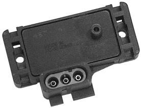
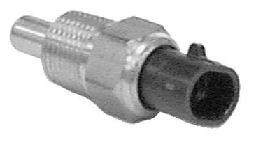
2 TABLE OF CONTENTS: 1.0 INTRODUCTION CHOOSING THE RIGHT SYSTEM: WARNINGS, NOTES, AND NOTICES PARTS IDENTIFICATION ADDITIONAL ITEMS REQUIRED FOR INSTALLATION TOOLS REQUIRED FOR INSTALLATION COOLANT TEMPERATURE SENSOR INSTALLATION REMOVAL OF EXISTING FUEL SYSTEM HP EFI TBI SYSTEM INSTALLATION Throttle Body Throttle Connections MAP Sensor Installation and Vacuum Line Connections Fuel Pump, Fuel Line, and Filter Installation Return Line Installation Oxygen Sensor Installation Oxygen Sensor Mounting Procedure Wiring Important Wiring Do s and Don ts ECU Connectors and Pinout Pinout Primary Sensors Connection Throttle Position Sensor (TPS) Manifold Air Pressure Sensor (MAP) Coolant Temperature Sensor (CTS) Manifold Air Temperature Sensor (MAT) Knock Sensor (Knock) Wide Band Oxygen Sensor (WB02) Fuel Pressure (Fuel) Oil Pressure (Oil) CANbus (CAN) Primary Outputs Idle Air Control (IAC) Fuel Injector Outputs (Injectors) Ignition Adapter (Ignition) Loose Wires Main Power Harness Ignition System Wiring Small Cap Computer Controlled GM HEI NON- ECU Controlled Timing Applications (ex. GM Non-ECU Controlled Large Cap HEI) Magnetic Crank Pickup Hall Effect Crank Pickup Programmable Inputs and Outputs Inputs Outputs
3 1.0 INTRODUCTION Holley Performance Products has written this manual for the installation of the HP EFI TBI fuel injection system. This manual contains the information necessary for the hardware installation. Please read all the WARNINGS, NOTES, and TIPS, as they contain valuable information that can save you time and money. It is our intent to provide the best possible products for our customer; products that perform properly and satisfy your expectations. Should you need information or parts assistance, please contact our technical service department at , Monday through Friday, 8 a.m. to 5 p.m. Central Time. By using this number, you may obtain any information and/or parts assistance that you may require. Please have the part number of the product you purchased when you call. NOTE: This manual is for the hardware installation of a Holley Throttle Body Fuel Injection System and instructions specific to it. Instructions on wiring harness installation, software operation, sensor operation, and tuning is contained on the disc supplied with the HP systems. NOTE: A laptop computer with a USB port is required for the installation and tuning of the HP system. WARNING! The HP EFI systems consist of a number of sophisticated components. Failure of any one component does not constitute, nor does it justify, warranty of the complete system. Individual service items are available for replacement of components. If assistance is required or if you need further warranty clarification, you can call Holley Technical Service at the number shown above. WARNING! To preserve warranty, these instructions must be read and followed thoroughly and completely before and during installation. It is important that you become familiar with the parts and the installation of the HP EFI system before you begin. Failure to read and understand these instructions could result in damage to HP EFI components that are not covered by the warranty and could result in serious personal injury and property damage. WARNING! The oxygen sensor in this kit is recommended for use with ONLY unleaded fuel. Use of leaded fuels will degrade the oxygen sensor and will result in incorrect exhaust gas oxygen readings and improper fuel delivery. Failure to follow these directions does not constitute the right to a warranty claim. WARNING! Failure to follow all of the above will result in an improper installation, which may lead to personal injury, including death, and/or property damage. Improper installation and/or use of this or any Holley product will void all warranties. WARNING! Use of some RTV silicone sealers will destroy the oxygen sensor used with this product. Ensure the RTV silicone sealant you use is compatible with oxygen sensor vehicles. This information should be found on the RTV package. 2.0 CHOOSING THE RIGHT SYSTEM: To ensure that you have purchased the correct HP EFI kit for your application, check to be sure that the kit you purchased is listed beside your engine s horsepower. NOTE: HP throttle body systems do not include fuel pump. HORSEPOWER KIT PART NUMBER Up to 525 hp HP EFI TBI, 900 CFM 75 lb/hr injectors Up to 600 hp HP EFI TBI, 900 CFM 85 lb/hr injectors 3
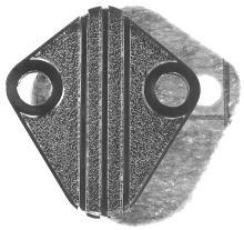
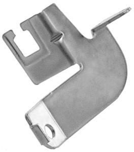
4 3.0 WARNINGS, NOTES, AND NOTICES WARNING! For the safety and protection of you and others, only a trained mechanic having adequate fuel system experience must perform the installation, adjustment, and repair. It is particularly important to remember one of the very basic principles of safety: fuel vapors are heavier than air and tend to collect in low places where an explosive fuel/air mixture may be ignited by any spark or flame resulting in property damage, personal injury, and/or death. Extreme caution must be exercised to prevent spillage and thus eliminate the formation of such fuel vapors. WARNING! This type of work MUST be performed in a well-ventilated area. Do not smoke or have an open flame present near gasoline vapors or an explosion may result. 4.0 PARTS IDENTIFICATION ITEM DESCRIPTION QTY SERVICE PART 1 TBI Assembly 700 CFM 65 lb/hr Complete TBI Assembly 900 CFM 72 lb/hr Complete TBI Assembly 900 CFM 85 lb/hr Complete HP EFI ECU HP EFI Software 1 N/A 4 HP EFI TBI Wiring Harness HP EFI Communications Cable 1 N/A 6 Metal Fuel Filter Fuel Filter (WIX 33033) 1 N/A 8 Fuel Filter Clamp 1 N/A 9 Fuel Pump Block-Off Plate & Gasket Wide Band Oxygen Sensor MAP Sensor Coolant Temperature Sensor Air Cleaner Adapter Air Cleaner Gasket Flange Gasket Manifold Flange Studs 4 N/A 17 Heat Insulator Gasket Oxygen Sensor Weld Ring AMP Relay (Pre-Installed in harness) Throttle Bracket 1 N/A 21 Throttle and Cruise Control Stud 1 N/A 22 Throttle Lever Ball 1 N/A 23 Throttle Lever Bracket 1 N/A 24 Ford kick down return spring 1 N/A 25 Throttle Lever Stud 1 N/A 26 Transmission Kickdown Stud 1 N/A 27 Hose Clamp 8 N/A 28 Grommet 1 N/A 29 Cable Ties 12 N/A 30 Tube Cap 1 N/A 31 Lockwasher 2 N/A 32 1/4-28 Nut 2 N/A 33 5/16-24 Nut 4 N/A 34 5/16" Vacuum Line 1 N/A TBI Service Parts: Air Charge Temperature Sensor Fuel Injector 900 CFM 72/75 lb/hr (requires purchase of 4) Fuel Injector 900 CFM 85 lb/hr (requires purchase of 4) Fuel Pressure Regulator Diaphragm Idle Air Control (IAC) Motor Throttle Position Sensor (TPS) Optional Parts: Small Cap GM HEI Ignition Adapter Ford TFI Ignition Adapter


5 Item 1 Item 2 Item 3 Item 4 Item 5 Item 6 Item 7 Item 8 Item 9 Item 10 Item 11 Item 12 Item 13 Item 14 Item 15 5


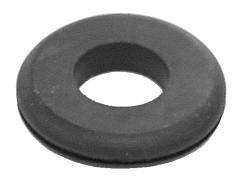
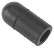
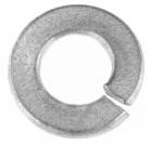
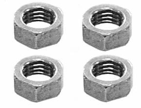

6 Item 16 Item 17 Item 18 Item 19 (Pre-Installed in Harness) Item 20 Item 21 Item 22 Item 23 Item 24 Item 25 Item 26 Item 27 Item 28 Item 29 Item 30 Item 31 Item 32 Item 33 Item 34 6
7 5.0 ADDITIONAL ITEMS REQUIRED FOR INSTALLATION 3/8" fuel hose (must meet SAE J30) 5/16" fuel hose (must meet SAE J30) 5/16" steel fuel line (must meet SAE J526) 0-30 psi fuel gauge Tee fitting for fuel gauge In addition to the above list, the engine must be equipped with a four barrel intake manifold and the vehicle must be in good operating condition. 6.0 TOOLS REQUIRED FOR INSTALLATION Standard wrench set Small blade screwdriver 5/32 Allen wrench Medium blade screwdriver #2 Phillips screwdriver Digital Volt-Ohm meter Drill and assorted bit sizes Hole saw (2 ) Terminal crimping tool Utility knife Factory Service Manual for your vehicle Windows laptop (XP, Vista, 7) An assistant is necessary for some installation and adjustment procedures and should be present for safety reasons. 7.0 COOLANT TEMPERATURE SENSOR INSTALLATION The coolant temperature sensor (item 12) must be installed in a coolant passage in either the intake manifold or cylinder head. The sensor has 3/8 NPT threads. If only a ½ NPT port is available, an adapter will have to be used. It is best to drain the some of the coolant before the sensor is installed. 8.0 REMOVAL OF EXISTING FUEL SYSTEM 1. Disconnect the battery and remove the air cleaner. 2. Before disconnecting any vacuum hoses, it is a good idea to sketch out the vacuum hose routing. Using masking tape and a permanent marker, mark all the vacuum hoses, vacuum sources, and ports before removing the old fuel delivery system. 3. Remove and discard the fuel line that connects the fuel delivery system from the fuel pump. This will not be needed in the installation. 4. Disconnect and plug the inlet fuel line that runs from the gas tank to the fuel pump. This will prevent fuel spillage and foreign matter or dirt from entering the fuel line. DANGER! Before disconnecting or removing fuel lines, ensure the engine is cold. Do not smoke. Extinguish all open flames. An open flame, spark, or extreme heat near gasoline can result in a fire or explosion causing property damage, serious injury, and/or death. 5. The fuel delivery system can now be removed. Holley recommends removing the mechanical fuel pump, if so equipped, and blocking-off the fuel pump mount using the provided fuel pump block off plate. The HP EFI system kit includes a block-off plate that will fit small and big block Chevrolet and Chrysler engines. If the block-off plate does not fit your engine, a block-off plate may have to be purchased from a local performance parts supplier. 6. If required, replace the intake manifold at this time. Proceed to step seven if this is not required. A 4-BARREL STOCK OR AFTERMARKET SQUARE FLANGE INTAKE MANIFOLD IS REQUIRED FOR THE INSTALLATION OF THE HOLLEY HP EFI TBI system. 7. Place clean shop towels or rags into the manifold opening to prevent dirt or debris from entering the engine. Keep exposed ends of the vacuum and fuel lines free from dirt. WARNING! Failure to cover the intake opening with a clean towel could result in dirt or debris entering the engine. Dirt or debris in the induction system can cause engine damage, which may necessitate in a complete engine overhaul. 8. Remove all traces of the old gasket material from the TBI mounting flange. DO NOT gouge the intake manifold sealing surface during removal of old gasket material. Failure to remove all traces of the old gasket material will result in vacuum leaks that will be difficult to detect later. Sealing flanges must be clean and dry before installation. 9. Remove the shop towels from the intake and vacuum out the intake channel to ensure no dirt or debris is left in the intake system. Place a shop towel over the entire intake opening until you are ready to install the new HP EFI TBI. 7

8 9.0 HP EFI TBI SYSTEM INSTALLATION 9.1 Throttle Body NOTE: A 4 barrel intake is required for the installation of the Holley HP EFI TBI system. NOTE: Some GM and Chrysler engines require the use of a manifold adapter Holley Part Number This adapts the spread bore carburetor manifold to the Holley square flange. 1. Install the heat spacer between the manifold and the 4 barrel throttle body injection unit. Check for sufficient thread engagement of the throttle body hold down studs and nuts. It may be necessary to purchase and install longer studs in the manifold for proper nut engagement. Gasket sealant may be used to ensure that no vacuum leaks occur. NOTE: If using a heat spacer, the flange gasket is not required. DANGER! Check for proper clearance between engine components, such as the distributor, coil, etc., and the throttle body. If any interference is found, correct the condition before continuing. Failure to do so can result in damage to the engine components or the throttle body. DANGER! Check for proper clearance between the air cleaner and the engine compartment cover hood. If any interference is found, correct the condition before continuing. Failure to do so can result in damage to the compartment cover or engine components. 2. Place the throttle body in position over the manifold flange studs with the IAC motor facing the front of the vehicle and the regulator/fuel connections towards the rear of the vehicle. 3. Tighten the throttle body down in a criss-cross pattern being careful not to over-tighten. Proper torque is 5-7 ft lbs. WARNING! Over tightening the TBI manifold flange hold-down-nuts may result in a warped or cracked throttle body. The TBI hold down nuts should be tightened down progressively in a criss-cross pattern to 5-7 ft./lbs., to prevent leaks and avoid causing damage to the throttle body. A TBI that has been damaged due to negligence of the owner will void the warranty. 9.2 Throttle Connections 1. Measure the length of the throttle lever arm on the carburetor removed from the vehicle. Compare the length of the existing throttle lever arm with the one on the HP EFI throttle body. If the two throttle lever arms are similar in length (within 1/2 of each other), the throttle lever arm hole on the HP EFI throttle body can be used without the extension bracket. Use the throttle lever arm extension bracket, if the old throttle lever arm is significantly longer than the new throttle lever arm. Before installation of the bracket, check the diameter of the throttle cable stud. Some systems may use a 1/4 stud that will require drilling of the appropriate hole in the extension bracket to a 1/4 diameter. Attach the extension bracket using two fillister head screws as shown in Figure 1. The extension lever length can be adjusted using the four sets of holes. 2. Attach throttle linkage and have an assistant get in the vehicle and fully actuate the throttle controls. Make the necessary adjustments to the throttle linkage to ensure that the throttle plates are vertical when the throttle control is wide open. Work the throttle linkage back and forth several times to ensure it operates smoothly with no binding or sticking. Figure 1 DANGER! Sticking throttle may result in uncontrolled engine or vehicle speed. This could cause property damage, personal injury, or death. A sticking throttle may be caused by improperly installed throttle cables, lack of clearance for any of the throttle linkage, or by a binding throttle linkage. Check all throttle cables for proper installation and alignment and actuate the throttle to check for any potential binding or clearance problems. Repair any problems before continuing. 8

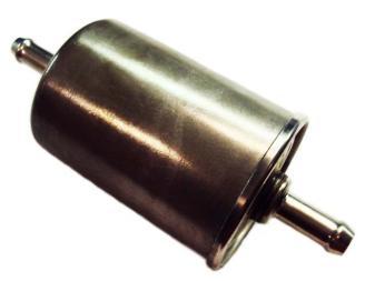
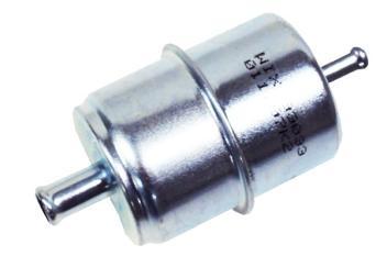
9 3. Locate the 1/4-28 throttle stud from the parts provided and attach to the throttle lever with the nut provided. Connect the accelerator linkage to the throttle stud on the throttle body. If the vehicle is equipped with an automatic transmission, connect the transmission kickdown rod to the linkage on the throttle body. The transmission kickdown may have to be adjusted. Follow the vehicle manufacturer s procedure for the correct adjustment procedure. NOTE: On late model GM and Ford overdrive transmissions, if the HP ECU is not being set up to control torque converter clutch lock up, a competent transmission shop must change the transmission electronic lockup to a mechanical lockup. Failure to do so will result in premature transmission failure. NOTE: On Chrysler vehicles, a lever extension will be needed, Holley Part Number Van applications may require the use of throttle lever extension Holley Part Number Attach throttle linkage and throttle return spring. Have an assistant get in the vehicle and fully depress the accelerator pedal. Make the necessary adjustments to the throttle linkage to insure that the throttle reaches wide-open position when the accelerator is depressed. Work throttle linkage back and forth several times to ensure that it operates smoothly with no binding or sticking. DANGER! Failure to attach the throttle return spring or a sticking throttle may result in uncontrolled engine or vehicle speed, which could cause personal property damage, serious injury, or death. 9.3 MAP Sensor Installation and Vacuum Line Connections 1. The MAP sensor must be installed as close to the vacuum source it is connected to as possible. It must be connected to a full manifold vacuum port. This is a vacuum source below the throttle body plates. The throttle body has a full manifold port that the sensor can be connected to (see Figure 2). It is best not to tee multiple items into the port that supplies the MAP sensor. The sensor should be mounted such that the vacuum port on the sensor is pointed at some downward angle above the vacuum source so that moisture does not collect in the sensor itself. 2. Install vacuum hoses to the appropriate port on the throttle body. Use the diagrams made during removal of the existing fuel system to locate the correct port. The vacuum ports of the throttle body are labeled in Figure Fuel Pump, Fuel Line, and Filter Installation NOTE: HP Throttle Body systems DO NOT include a fuel pump. The installer can use their in-tank or in-line pump of choice. Holley offers in-line and in-tank EFI fuel pumps. P/N is an inline pump rated for up to HP naturally aspirated engines. It is the recommended in-line pump for Holley 4bbl TBI systems. NOTE: If you have dual fuel tanks, you must purchase Holley PN The following section covers the installation of an in-line pump such as Holley PN Holley includes both a pre and post filter with the HP TBI system. Both of these filters have barbed ends and are designed to connect to an EFI pressure rated rubber hose. They are not designed for AN style plumbing. 1. Do not mount the fuel pump higher than the lowest point of the fuel tank. 2. Make sure fuel tank is properly vented. DANGER! Never get under a vehicle supported only by a jack. Serious injury or death can result from vehicles falling off of jacks. Before working underneath a vehicle, support it solidly with jack stands. 3. Mount the electric fuel pump as close to the fuel tank outlet as possible with the bracket provided. Mounting the fuel pump in this manner will insure that the pump will prime easily and purge fuel vapors in the TBI quickly to ensure faster starts. DANGER! Take precautions to ensure that all fuel line routings are away from heat sources, such as the engine or exhaust pipes. A fire or explosion hazard could cause serious injury or death. DANGER! Ensure that the fuel pump mounting location will not interfere with any under the vehicle components, especially at the extreme limits of the suspension travel. A fire or explosion hazard could cause serious injury or death. 9

10 Figure 3 4. There are two metal filters included with the system. The filter marked MUST be installed between the fuel tank and the fuel pump inlet (unless an in-tank pump is used). The purpose of this filter is to protect the fuel pump from particles of dirt or other foreign material. The filter should be installed with the arrow on the filter pointing in the direction of the fuel flow. 5. The other metal fuel filter that is included with the EFI TBI system should be installed between the electric pump outlet and TBI unit. This is a 10 micron EFI filter. Position the filter, so the fuel hoses can be routed without kinks or sharp bends. The filter should be installed with the arrow on the filter pointing in the direction of the fuel flow. A clamp is provided to assist with mounting this filter in the kit. WARNING! Ensure both filters are installed in the proper direction. A flow direction arrow is stamped on the side of the filter to indicate the direction of fuel flow. Failure to do so will result in a system malfunction. DANGER! Take precautions to ensure all fuel line routings are away from heat sources, such as the engine or exhaust system. A fire or explosion hazard could cause property damage, serious injury, and/or death. 6. Plumbing must now be installed to connect the fuel tank to the filters, pump, and TBI unit. It is recommended to use steel hard line or stainless braided hose with AN fittings. If AN plumbing is used, the appropriate fittings must be purchased for the pump and TBI unit. Filters must have AN style fittings as well. The thread in the inlet and outlet fittings of the TBI unit is ¼ NPT. 7. 3/8 line should be used on the feed/pressure side of the system (the filters included are designed for 3/8 line). If using steel line, rubber hose (rated for use with fuel injection) can be used to connect the steel line to the pump and filters. You should not connect a rubber hose directly to a steel line unless the end of the line has a bead/nipple or barb that retains the hose (similar to the ends of the fuel filters). If the steel line is just cut off, purchase a compression fitting that a barbed hose end can be installed on, or use a tool to roll a bead/nipple on the end of the steel line. Install hose clamps on all of these junctions (8 are included in the kit). All fuel hoses used must meet SAE J30 performance standards. All steel fuel line must meet SAE J526 standards. 8. The TBI unit has an inlet and an outlet fitting. The inlet fitting is designed for a 3/8 hose and is on the drivers side (linkage side) of the throttle body. The return line (designed for a 5/16 hose) is on the passenger side (side with the TPS). 9. If you plan to install a fuel pressure gauge, do so at this time. The 4 bbl TBI systems are designed for an operating pressure of 21PSI. Although this is factory pre-set, it is ideal that it be checked. The TBI units have an 1/8 NPT plug on the drivers side that can be used to temporarily install a gauge (this location will interfere with the throttle cable on a permanent install) to set the pressure. Holley also sells a PSI pressure transducer (PN ) that plugs into the fuel connector on the main harness. This sensor can be installed anywhere between the fuel pump and the TBI unit. It has a 1/8 NPT male thread. 10
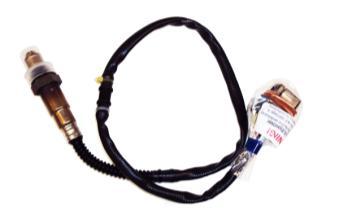
11 10. If using the existing fuel lines, inspect and replace any hose, clamps, or fuel line showing ANY sign of aging. DANGER! Failure to use a fuel hose that meets SAE J30 standards could result in fuel leaks. A fuel leak may result in a fire or explosion hazard, which could cause serious injury or death. DANGER! Failure to use a steel fuel line that meets SAE J526 standards could result in fuel leaks. A fuel leak may result in a fire or explosion hazard, which could cause serious injury or death. DANGER! Take precautions to ensure that all fuel line routings are away from heat sources, such as the engine or exhaust pipes. A fire or explosion hazard could cause serious injury or death. DANGER! Rigid fuel line tubing should be used for under vehicle runs, such as along vehicle frame rails or under floor pans. Failure to do so is a potential fire or explosion hazard, which could cause serious injury or death. 11. Anchor all fuel lines securely to solid chassis members at 1 ½ foot intervals using rubber coated steel clamps. Use of only approved steel fuel line tubing will afford maximum fuel line protection against road hazards and premature wearing due to flexing, temperature extremes, road salt, weather, etc. 9.5 Return Line Installation The Holley HP EFI TBI system requires a return fuel line to the fuel tank. Some late model vehicles that were originally equipped with a throttle body injection system may already have a return line to the fuel tank that can be utilized. If a return fuel line must be installed, a minimum size of 5/16 I.D. is recommended. The return line is on the passenger side of the TBI unit. The fitting on the TBI unit is designed for a 5/16 line. If a larger line is used, use an appropriate fitting on the throttle body. The return line must not present a pressure restriction to the return fuel flow. There should never be more than approximately 3 PSI of pressure in the return line. A line that is too small, or has restrictions will cause tuning problems with the system. DANGER! Do not use the vapor canister lines as a fuel return line. Possible fuel leaks may create a fire or explosion hazard, causing serious injury or death. WARNING! Use only approved steel fuel line. The return fuel line should enter the fuel tank at the fuel level sending unit flange or at the filler neck. The filler neck or sending unit must be removed from the tank to perform this operation. DANGER! Proper installation of the fuel return line may necessitate complete removal of the fuel tank. This work should be done by a fuel tank specialist, who regularly does this work and is familiar with safety regulations and precautions necessary to do this work. If a person attempts this work, who is not familiar with the safety regulations and precautions, an explosion hazard may result causing serious injury or death. 9.6 Oxygen Sensor Installation Figure 5 The oxygen sensor should be mounted at a point where it can read a good average of all the cylinders on one bank. This would be slightly after all the cylinders merge. 11
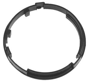
12 9.6.1 Oxygen Sensor Mounting Procedure NOTE: Someone with experience in welding exhaust systems should install the oxygen sensor boss. Any competent exhaust shop will be able to perform this task at a minimum cost. WARNING! Use of leaded fuel will degrade an oxygen sensor. Prolonged use is not recommended unless periodic replacement is performed. WARNING! Use of some RTV silicone sealers will destroy the oxygen sensor used with this product. Ensure the RTV silicone sealant you use is compatible with oxygen sensor vehicles. This information should be found on the RTV package. 1. Locate a position for the oxygen sensor as close to the engine as possible. If your vehicle has catalytic converters, the oxygen sensor MUST be located between the engine and the catalytic converters. Figure 6 NOTE: The oxygen sensor should be mounted in such a way that the condensation in the exhaust tubing will not enter the sensor. Mount the O 2 sensor in the upper half of the exhaust tubing, with the angle x, shown above, being greater than 10. The picture above indicates that the sensor can be mounted on either side of the exhaust tubing. 2. Drill a 7/8 hole in the location picked for the sensor. Weld the threaded boss into the 7/8 hole. Weld all the way around the boss to insure a leak proof connection. Install the oxygen sensor into the threaded boss and tighten securely. It is a good idea to add anti-seize to the threads to aid in removal. 3. On vehicles equipped with an AIR pump, the oxygen sensor must be mounted before the AIR injection into the exhaust, or the AIR pump must be disconnected. Holley recommends that if the AIR is injected into both exhaust manifolds, mount the oxygen sensor into the pipe immediately after the exhaust manifold. Disconnect the AIR pump tube from the exhaust manifold and plug both ends. Check with local ordinances for the legality of this procedure in your area. WARNING! Failure to disconnect the AIR pump or locating the oxygen sensor downstream from AIR injection will result in an extremely rich mixture, which could cause driveability problems and severe engine damage. WARNING! It is important that the distribution ring is properly installed and fastened to the throttle body. Failure to do so will cause an inadequate seal between the throttle body and air cleaner and may be a fire hazard in the event of a backfire. Fire hazard can result in property damage, serious injury, and/or death. 12

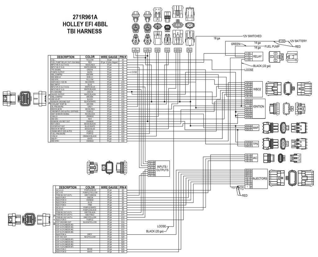
13 10.0 Wiring The following overviews how to properly install the wiring harnesses for this system Important Wiring Do s and Don ts An EFI system depends heavily on being supplied a clean and constant voltage source. The grounds of an electrical system are just as important as the power side. HP ECU s both contain multiple processing devices that require clean power and ground sources. The wiring harnesses for them must be installed in such a manner that they are separated from dirty power and ground sources. DO S Install the main power and ground directly to the battery. Keep sensor wiring away from high voltage or noisy/dirty components and wiring, especially secondary ignition wiring, ignition boxes and associated wiring. Use shielded/grounded cable that is supplied for wiring crankshaft and camshaft signals. Properly solder and heat shrink any wire connections. It is critical that the engine has a proper ground connection to the battery and chassis. DON TS NEVER run high voltage or noisy/dirty wires in parallel (bundle/loom together) with any EFI sensor wiring. If wires need to cross, try to do so at an angle. Do not let Crank and Cam signal wiring near spark plugs and coil wires. Do not run non-shielded/grounded wire for crankshaft and camshaft signals, especially magnetic pickups. Do not run the USB Communications cable near or with any noisy wires. Do not exceed the current limits provided for the various outputs. If current levels exceed these, use the appropriate relay or solenoid drivers. Do not use improper crimping tools. Don t use things like t-taps, etc. Use solder and heat shrink. It is never recommended to splice/share signal wires (such as TPS, etc) between different electronic control units. Don t wire items that require clean ground or power to the same points ECU Connectors and Pinout Battery Power Connection The HP ECU has a main battery power and ground connector on the right side of the ECU. The bottom position, Terminal A is the ground. The upper position, Terminal B is the positive terminal. Always use the fused power cable with the proper connectors supplied by Holley only. USB Communications Connector HP ECU s use a standard USB cable for Laptop communications Looking at the front, the connector is at the far left side. This connection is a common mini USB connector, typically used for digital cameras and other devices. Holley offers a USB cable with a sealed connector, PN for applications where the USB cable will be plugged in, and the ECU is mounted in a dirty environment. HP ECU The HP ECU has two main connectors: P1A - The first connector next to the USB connector is the P1A connector (34 pin). This connector is primarily an Input connector. It contains all the sensor inputs and wide band oxygen sensor control. P1B - The second connector is the P1B connector (26 pin). This connector is the output connector. It has 8 injector outputs, 8 DIS ignition outputs, 4 IAC outputs, and 4 user programmable outputs. Figure 7 13
14 11.1 Pinout The following is a pinout of the HP ECU connectors. The P1A and P1B connectors and pinout are identical for the HP and Dominator ECU's. P1A Connector P1B Connector Pin Function Pin Function A1 Coil - Input B1 IAC A Lo A2 Fuel Pump Out (+12v) (10A Max) B2 IAC A Hi A3 Input #2 (F52THG) B3 Output #4 (G P-) A4 Input #4 (F5G) B4 Injector F Output A5 TPS Input B5 Injector G Output A6 Points Trigger Output B6 Injector H Output A7 WB1 COMPR2 B7 Injector E Output A8 WB1 Shield B8 IAC B Lo A9 WB HTR - B9 IAC B Hi A10 Switched +12v Input B10 Output #3 (G P-) A11 Manifold Air Temp Input B11 Output #2 (H P+) A12 Input #1 (F52THG) B12 Output #1 (H P+) A13 Input #3 (F5G) B13 Injector D Output A14 Cam/Crank Ground B14 EST Ground Output A15 Gauge Digital Output B15 EST 2 Output (Cylinder #2) A16 WB1 COMPR1 B16 EST 4 Output (Cylinder #4) A17 WB1 VS-/IP+ B17 EST 6 Output (Cylinder #6) A18 Sensor Ground B18 EST 8 Output (Cylinder #8) A19 Engine Coolant Temp Input B19 Injector A Output A20 Oil Pressure Input B20 EST 12V Output A21 Knock #2 Input B21 EST 1 Output (Cylinder #1) A22 Cam Sync Input / Ignition Bypass Output B22 EST 3 Output (Cylinder #3) A23 Map Sensor Input B23 EST 5 Output (Cylinder #5) A24 CAN Lo B24 EST 7 Output (Cylinder #7) A25 WB1 VS+ B25 Injector C Output A26 Sensor +5v B26 Injector B Output A27 NOT USED A28 EST/Spout Output A29 Knock #1 Input A30 Crank Speed Input A31 Fuel Pressure Input A32 CAN Hi A33 WB1 IP+ A34 WB HTR Primary Sensors Connection These sections are an overview of all the connections that must be completed on the Main Harness. The Main Harness is the primary harness that supports all the primary engine sensors, fuel and ignition for 8 cylinder engines, the #1 wideband oxygen sensor, and the four programmable input and output channels. There are two connectors for this harness designated as P1A (pin designations below that start with an A) and P1B (pin designations below that start with a B). The following descriptions indicate the name of the item and the name as labeled on the harness (each connector has a label) is shown in parenthesis. 14
15 12.1 Throttle Position Sensor (TPS) Connect to the TPS which is located on the throttle body Manifold Air Pressure Sensor (MAP) A 1 Bar MAP sensor is provided with all Holley EFI systems. Connect to the MAP sensor Coolant Temperature Sensor (CTS) Connect to the Coolant Temperature sensor which should have been installed in an engine coolant passage Manifold Air Temperature Sensor (MAT) Connect to the Air Temperature Sensor (see Figure 2). Multiport systems will have this installed in the intake manifold and TBI systems will have it installed in the throttle body air inlet Knock Sensor (Knock) Holley EFI systems work with either a one wire or two wire knock sensor. Application specific harnesses will have the correct knock sensor connections installed on the harness. A Universal harness comes with a 3 pin metripak connector. If a knock sensor is added, it should be connected into this connector 12.6 Wide Band Oxygen Sensor (WB02) Holley EFI systems can work with either a Bosch (PN ) or NTK (PN ) wide band oxygen sensor. These sensors must be purchased from Holley as they are calibrated specifically for use with Holley EFI systems. HP EFI systems are sold with the Bosch sensor. Make sure you have the proper sensor selected in the Engine Parameters area or sensor damage may occur. Connect the WB02 connector to the WB02 sensor which should be installed in the exhaust system Fuel Pressure (Fuel) A fuel pressure transducer connector is pre-installed in the main harness. The system is plug-and-play configured for a Holley 100 PSI pressure transducer (can be purchased under PN ). A different 0-5V transducer can be used, but the calibration must be set up as a custom sensor in the software. If these are not connected to a pressure transducer, the Fuel and Oil Pressure will read LOW Err in the data monitor. This will not cause any issues. NOTE: Connect to the transducer (if installed) Oil Pressure (Oil) An oil pressure transducer connector is pre-installed in the main harness. The system is plug-and-play configured for a Holley 100 PSI pressure transducer (can be purchased under PN ). A different 0-5V transducer can be used, but the calibration must be set up as a custom sensor in the software. If these are not connected to a pressure transducer, the Fuel and Oil Pressure will read LOW Err in the data monitor. This will not cause any issues. NOTE: Connect to the transducer (if installed) CANbus (CAN) All harnesses have a CANbus communications connector. This is used to communicate with CANbus devices such as the Avenger Handheld tuning module or the 5.7 Touch Screen LCD. If these devices or any other CANbus device is not being used, there is no need to do anything with this connector. A24 CAN Lo (Pin B) A32 CAN Hi (Pin A) 13.0 Primary Outputs 13.1 Idle Air Control (IAC) Connect to the idle air control motor which is installed in the throttle body. 15
16 13.2 Fuel Injector Outputs (Injectors) All terminated harnesses have a fuel injector connector. Various fuel injector harnesses plug into this connector. It is essential these harnesses are used so that injector firing sequence is maintained. Note that for engines with different firing orders, you do NOT change these pins. The engine s firing order is input in the software itself. V8 harnesses offered by Holley are labeled for GM, Ford, and Chrysler engines. Each injector harness has the engine cylinder number labeled on each injector connector. Connect each injector on the appropriate cylinder Ignition Adapter (Ignition) The Ignition Adapter connector contains all the wires needed to connect to adapter harnesses offered by Holley for various ignition systems and crank and cam sensor. The only ignition related wiring that is NOT contained on this connector is individual coil driver outputs for DIS applications. The adapter is pinned as follows: A30 Crank signal Input - Both digital and inductive (proper type must be selected in the software) (Pin A) A22 Cam signal Input / Ignition Bypass Output Both digital and inductive (proper type must be selected in the software) NOTE: If using a computer-controlled GM HEI Distributor, this pin will serve as the ignition bypass output (Pin B) A14 IPU Ground (Pin C) Chassis Ground (Pin D) A10 Switched +12v (Pin E) A27 NOT USED (Pin F) A14 IPU Ground (Pin G) A28 EST/Spout Output (Pin H) A14 Shield Ground (Pin J) A14 Shield Ground (Pin K) NOTE: The crank and cam input wiring in both the main harness and adapter harnesses use a shielded/grounded cable. The shield is grounded at the ECU end. You do not ground both end of shielded/grounded cable. It is always recommended to use shield/grounded cable to protect the integrity of the crank or cam sensor input signals. This is especially important when using a magnetic pickup. A hall effect sensor is much less susceptible to noise interference and is always the recommended sensor type to use. Holley offers the following ignition adapter harnesses Magnetic Pickup Harness Intended for magnetic pickups. Either crank trigger or distributor mounted - Does not contain cam sync wiring HEI Connects to a small cap GM HEI computer controlled distributor Ford TFI Connects to a Ford TFI Distributor Universal Unterminated Ignition Harness Contains ignition adapter connector and all wiring to connect to any crank and cam sensors (pins A-K). Also, contains shielded/grounded cable for crank and cam sensor inputs. The user must supply terminals and connectors to plug into their chosen sensors. NOTE: See section 16.0 for applications and diagrams on wiring most ignition systems Loose Wires The following loose wires in the main wiring harness should be connected as follows on all systems: 12V Switched Color = Red/White Should be connected to a clean +12 volt power source. Power source should only be active when the ignition is on. Make sure source has power when engine is cranking as well. Not all sources apply power when the ignition switch is in cranking position. 12V Battery Color = Red Should be connected directly to the battery. There is a fuse holder attached that should contain a 20A rated fuse. This powers the fuel pump and fuel injectors. 12V Fuel Pump Color = Green - Used to directly power a fuel pump (+12 volt). Fully terminated harnesses utilize a relay to supply this power. 14 gauge wire is used. Due to this, it is not recommended for pumps that draw over Amps to use this wire. For high current pumps, use this wire to trigger a separate relay and use larger gauge wire to feed the pump - 10 gauge is recommended. 16
17 Points Output Color = White Used to trigger a CD ignition box. See the ignition wiring section for detailed wiring. Ignition/DIS Chassis Ground Color = Black Connect to a ground point that has excellent connectivity with both the engine and the battery. Coil Color = Yellow Used for an RPM input signal when not controlling timing and NOT running a Capacitive Discharge (MSD) ignition system. See the ignition wiring section 8.0 for detailed wiring. WARNING! Connecting this wire to the coil of a CD ignition will damage the ECU Main Power Harness Holley HP and Dominator ECU s use the same main power cable. These wires should be run directly to the battery. 10 gauge wire is used. The harness comes with a 40 Amp fuse pre-installed. Do not substitute smaller gauge wires Ignition System Wiring Both the HP and Dominator Systems support a wide variety of ignition systems. The following schematics show how to wire the most typical systems Small Cap Computer Controlled GM HEI To connect to a small cap computer controlled GM HEI, ignition adapter harness PN is required. The following diagrams overview how to wire with and without a CD ignition box. Figure 8 17
18 Figure NON- ECU Controlled Timing Applications (ex. GM Non-ECU Controlled Large Cap HEI) To connect to a distributor that has mechanical advance and is not controlled by the ECU (ex. GM large cap HEI non-computer controlled distributor), refer to the following diagrams. If NOT using a CD ignition box, connect the loose YELLOW (NOT yellow/black wire) in the harness to the negative side of the ignition coil. If using a CD ignition box, connect the purple crank input wire located in the ignition adapter harness to the tach out in the ignition box. This wire is located in Pin A of the 10 pin ignition adapter in the EFI harness (Do NOT use the purple wire in pin B this is for the camshaft sensor input). The following shows three options in order of preference: 1) Some kits come with a 10 pin ignition adapter harness with a single YELLOW/BLACK wire that directly connects to the ignition adapter on the main harness. If you have this adapter, use it to connect the YELLOW/BLACK wire into the tach output of the CD ignition box. 2) If your kit contains an HEI distributor ignition adapter harness (4 wires), you can cut and splice into the YELLOW/BLACK wire in it. This saves you from having to modify the main harness. 3) If you have no ignition adapter harness, you can splice into the purple wire in the main harness. If splicing is done, make 100% certain that this is a very solid connection. Solder and heat shrink is highly recommended. This supplies the engine speed signal to the ECU and if the connection is not solid, the engine will not run properly. 18
19 Figure 10 Figure 11 19
20 16.3 Magnetic Crank Pickup The follow diagrams are for running a magnetic pickup, either a crank trigger or a distributor. To run just a magnetic pickup crank input and no camshaft input, PN should be purchased. If a cam sync input will be used as well, it is recommended to use PN which will contain wiring for both the crank and cam sensor inputs. It is critical that properly installed shielded and grounded cable is used when using a magnetic pickup, or it is likely that EMI will disturb the crankshaft signal. Both PN and come with the proper cabling. It must be installed properly as well. Make sure that the shield is properly grounded which requires it being grounded at the ECU with that ground maintained through the ignition adapter connection. Note: The user must supply the proper terminals/connectors for the crank and cam sensors they are using. Figure 12 20
21 16.4 Hall Effect Crank Pickup The follow diagrams are for running a hall effect pickup, either a crank trigger or a distributor. It is recommended to use PN which will contain wiring for both the crank and cam sensor inputs. It is important that properly installed shielded and grounded cable is used when using a hall effect input. PN comes with the proper cabling. It must be installed properly as well. Make sure that the shield is properly grounded which requires it being grounded at the ECU with that ground maintained through the ignition adapter connection. Figure 13 21
22 17.0 Programmable Inputs and Outputs Programmable input and outputs are intended to be any input or output that is created by the user when a Global Folder is configured. Once configured, they must be assigned a to a specific pin location on the Pin Map, and then physically wired per the assigned location. The HP ECU has an Input/Output connect on the main harness. This is an 8 pin metripak connector. Programmable inputs and outputs can be connected into this connector. PN is a harness that plugs into this connector. If you do not want to purchase this harness, use alternative methods to connect to these 8 wires. This connector is as follows. The functions are described below. Input/Output Connector Pin ECU Pin Wire Color Function A P1-A12 White/Blue F 5 2 T H G B P1-A3 White/Red F 5 2 T H G C P1-A13 White/Black F 5 G D P1-A4 White/Green F 5 G E P1-B12 Grey/Yellow P+ H F P1-B11 Grey/Red P+ H G P1-B10 Grey/Black P- G H P1-B3 Grey/Green P- G 17.1 Inputs There are six types of inputs that can be configured. The following lists them and reviews wiring recommendations. The designation on the Pin Map (Inputs) is given first, then a description. 1. H Switched 12v or High Side input This input will be triggered when system voltage is applied. Minimum triggering voltage is 4.5v. Do not exceed 24v. Wiring: Connect up to any voltage source that is desired to trigger this input. 2. G Switched Ground or Low Side input This input will be triggered when a ground is applied. Wiring: Connect up to any ground source that is desired to trigger this input volt sensor input Any 0-5 volt sensor input such as a TPS, MAP sensor, pressure transducer, and many others. Wiring: Wire the signal wire from the 0-5v sensor used into the appropriate pin. Any 0-5v sensor requires a +5v reference voltage and a sensor ground. On an HP, the user must tie into the existing +5v reference and Sensor Ground lines (which go to any of the 5v sensor such as MAP, TPS, etc). These wires are as follows: Connector Sensor +5v Reference Voltage Pin Sensor Ground Pin P1A A26 (Orange) A18 (Black White) It is acceptable to have multiple sensors share the same +5v and ground reference lines. Be sure to solder, heat shrink, etc wires properly as poor connections will cause for inaccurate or faulty sensor readings. Do not use +5v reference or ground sources from other controllers or power supplies to support the sensor, or sensor accuracy may be compromised volt sensor input Any 0-20 volt sensor input Wiring: Connect to desired voltage input. 5. T Thermistor temperature input Most coolant and air temperature sensors are a 2 wire thermistor design. Wiring: Connect to one side of the thermistor device. Connect the other side of the thermistor device to a Sensor Ground input pin to the ECU (same pins for a 0-5v sensor). These pins are as follows: Connector P1A Sensor Ground Pin A18 22
23 6. F Frequency or a Digital Speed Input Designed for a digital voltage input from a speed/rotation sensor. A hall effect sensor is the common sensor used. Voltage range can be 4.5 to 24 volts. Wiring: A hall effect sensor has 3 wires: Signal, Power, and Ground. Most sensors can be supplied with battery voltage (12v), a few require a 5 volt reference. Check with the specifications of your specific sensor. Although not usually needed with a hall effect sensor, it is always advised to use a shielded/grounded cable to wire them (all three wires can be shielded). The following is advised when wiring a hall effect sensor. Signal Run the sensor signal wire into the Pin Mapped channel. Power Either supply with clean switched power, or if it is not used for another purpose, you can power from Pin P1B-B20 which is a clean 12v power source. If the sensor requires 5 volts, use a +5v reference line. Ground It is best to connect to an IPU (Inductive/Magnetic Pickup) or Sensor Ground. The following pins are IPU grounds: Connector P1A Sensor Ground Pin A14 Shield Wire If using shielded/grounded cable, connect the shield ground wire to the ECU only - best to connect it to an IPU ground Outputs All PWM (Pulse Width Modulated) and switched outputs are rated at a maximum of 2A. If a device will draw more than 2A, some type or relay must be used. If the output is PWM, do not use a switching relay, but rather a solid state type relay designed to be pulse width modulated. There are four types of outputs that can be configured. The following lists them and reviews wiring recommendations. The designation on the Pin Map (Outputs) is given first, then a description. 1. H Switched 12v or High Side output will output system voltage level. Wiring: Connect the pin to the device to be triggered. 2. G Ground or Low Side output will output a ground trigger. Wiring: Connect the pin to the device to be triggered. 3. P+ - 12v Pulse Width Modulated output Outputs a high side pulse width modulated output to control items such as a progressive nitrous solenoid or a PWM IAC will output system voltage level. Wiring: Connect the pin to the device to be triggered. A PWM device has 2 wires, connector the other side of the device to ground. 4. P- Ground Pulse Width Modulated output Outputs a low side pulse width modulated output to control items such as a progressive nitrous solenoid or a PWM IAC. Wiring: Connect the pin to the device to be triggered. A PWM device has 2 wires, connector the other side of the device to a voltage source. 23
24 Holley Performance Products 1801 Russellville Road Bowling Green, KY Technical Service: Fax: For online help, please refer to the Technical Information section of our website: 199R10507 wf Date:
25 25
EFI HARNESS KIT , & Kit Contents: Power Harness : All Kits
 EFI HARNESS KIT 558-500, 558-501 & 558-502 Kit Contents: Main Harness 558-102: Kits 558-500 558-103: Kits 558-501 & 502 Power Harness 558-308: All Kits Injector Harness 558-200: Kits 558-500 & 502 558-201:
AVENGER EFI 4 BBL TBI SYSTEMS
 AVENGER EFI 4 BBL TBI SYSTEMS 550-400 (700 CFM 65 lb/hr injectors) up to 400 HP 550-401 (900 CFM 75 lb/hr injectors) up to 525 HP 550-402 (900 CFM 85 lb/hr injectors) up to 600 HP TBI HARDWARE INSTALLATION
FUEL KITS P/N & 526-4
 FUEL KITS P/N 526-3 & 526-4 NOTE: These instructions must be read and fully understood before beginning installation. If this manual is not fully understood, installation should not be attempted. Failure
HP EFI UNIVERSAL RETROFIT KITS
 HP EFI UNIVERSAL RETROFIT KITS 550-500 (HP Universal Retrofit Kit for 4150 carb style intakes) 550-501 (HP Universal Retrofit Kit for 4500 carb style intakes) INSTALLATION INSTRUCTIONS 199R10510 NOTE:
WIRING MANUAL & DIAGRAMS 199R10555
 WIRING MANUAL & DIAGRAMS 199R10555 HP EFI and Dominator EFI Systems Contents 1.0 Manual Overview... 2 1 1.1 Important Wiring Do s and Don ts... 3 2.0 ECU Installation, Connectors, and Pinout... 3 2.1 Pinout...
FUEL KITS P/N & 526-2
 FUEL KITS P/N 526-1 & 526-2 NOTE: These instructions must be read and fully understood before beginning installation. If this manual is not fully understood, installation should not be attempted. Failure
StealthRam Small Block Chevy Multi-Port EFI Systems Standard and Vortec Intake Versions
 StealthRam Small Block Chevy Multi-Port EFI Systems Standard and Vortec Intake Versions 550-820 (Early/Late Heads) 550-823 (Early/Late Heads) Polished 550-828 (Vortec Heads) Polished NOTE: Fuel pump and
Sniper EFI Fuel Kits P/N 526-5/526-8 (20 ft. hose) & (40 ft. hose)
 & (40 ft. hose)") Sniper EFI Fuel Kits P/N 526-5/526-8 (20 ft. hose) & 526-7 (40 ft. hose) 1.0 FUEL SYSTEM INSTALLATION DANGER! Take precautions to ensure that all fuel components are away from heat sources, such as the
Sniper EFI Fuel Kits P/N 526-5/526-8 (20 ft. hose) & 526-7 (40 ft. hose) 1.0 FUEL SYSTEM INSTALLATION DANGER! Take precautions to ensure that all fuel components are away from heat sources, such as the
AVENGER EFI 4 BBL MPFI SYSTEMS
 AVENGER EFI 4 BBL MPFI SYSTEMS SINGLE PLANE 4BBL SMALL BLOCK CHEVY MULTI-PORT EFI SYSTEMS 550-811 (Early/Late Models) 550-816 (Vortec Heads) SINGLE PLANE 4BBL BIG BLOCK CHEVY MULTI-PORT EFI SYSTEMS 550-831
StealthRam Small Block Chevy Multi-Port EFI Systems Standard and Vortec Intake Versions
 StealthRam Small Block Chevy Multi-Port EFI Systems Standard and Vortec Intake Versions 550-821 (Early/Late Heads) 550-822 (Early/Late Heads) Polished 550-826 (Vortec Heads) 550-827 (Vortec Heads) Polished
4 BBL THROTTLE BODY FUEL INJECTION SYSTEM
 4 BBL THROTTLE BODY FUEL INJECTION SYSTEM 550-405 950 CFM 200-600 HP Polished Aluminum 550-406 950 CFM 200-600 HP Hard Core Gray INSTALLATION MANUAL 199R10653 NOTE: These instructions must be read and
INSTALLATION TUNING AND TROUBLESHOOTING MANUAL
 Part Number 501-12 Pro-Jection 1D, 300 CFM INSTALLATION TUNING AND TROUBLESHOOTING MANUAL These instructions must be read and fully understood before beginning installation. If this manual is not fully
INSTALLATION, TUNING, AND TROUBLESHOOTING MANUAL
 MARINE Part Number 700-21 For V-8 Engines 2D INSTALLATION, TUNING, AND TROUBLESHOOTING MANUAL NOTE: These instructions must be read and fully understood before beginning installation. If this manual is
EDELBROCK THUNDER SERIES AVS CARBURETORS Part #1801, 1802, 1803, 1804, 1805, 1806, 1812, 1813, 1825, 1826 INSTALLATION INSTRUCTIONS
 EDELBROCK THUNDER SERIES AVS CARBURETORS Part #1801, 1802, 1803, 1804, 1805, 1806, 1812, 1813, 1825, 1826 INSTALLATION INSTRUCTIONS IMPORTANT NOTE: Proper installation is the responsibility of the installer.
POWER PACK 4 BBL MPFI SYSTEMS
 POWER PACK 4 BBL MPFI SYSTEMS SINGLE PLANE 4BBL SMALL BLOCK CHEVY POWER PACK SYSTEMS 550-700 (Early/Late Models) 550-701 (Vortec Heads) SINGLE PLANE 4BBL BIG BLOCK CHEVY POWER PACK SYSTEMS 550-702 (Std
DISTRIBUTORLESS IGNITION SYSTEM Installation and Adjustment Instructions
 DISTRIBUTORLESS IGNITION SYSTEM Installation and Adjustment Instructions 1.0 INTRODUCTION: Congratulations on your purchase of a Holley Distributorless Ignition System! Holley cannot and will not be responsible
4 BBL THROTTLE BODY FUEL INJECTION MASTER KIT
 4 BBL THROTTLE BODY FUEL INJECTION MASTER KIT 550-405K 950 CFM Polished Aluminum Throttle Body + Complete Fuel System 550-406K 950 CFM Hard Core Gray Throttle Body + Complete Fuel System FUEL INJECTION
EDELBROCK THUNDER SERIES AVS CARBURETORS Part #1801, 1802, 1803, 1804, 1805, 1806, 1812, 1813, 1825, 1826 INSTALLATION INSTRUCTIONS
 EDELBROCK THUNDER SERIES AVS CARBURETORS Part #1801, 1802, 1803, 1804, 1805, 1806, 1812, 1813, 1825, 1826 INSTALLATION INSTRUCTIONS PLEASE study these instructions carefully before beginning this installation.
QUICK START GUIDE 199R10546
 QUICK START GUIDE 199R10546 1.0 Overview This contains detailed information on how to use Holley EFI software and perform tuning that is included within the software itself. Once you load the software,
HP FUEL PUMPS P/N & Installation Instructions 199R10569
 HP FUEL PUMPS P/N 12-700 & 12-890 Installation Instructions 199R10569 WARNING! THESE INSTRUCTIONS MUST BE READ AND FULLY UNDERSTOOD BEFORE BEGINNING INSTALLATION. FAILURE TO FOLLOW THESE INSTRUCTIONS MAY
DOMINATOR FUEL PUMPS P/N & Installation Instructions 199R10573
 DOMINATOR FUEL PUMPS P/N 12-1400 & 12-1800 Installation Instructions 199R10573 WARNING! THESE INSTRUCTIONS MUST BE READ AND FULLY UNDERSTOOD BEFORE BEGINNING INSTALLATION. FAILURE TO FOLLOW THESE INSTRUCTIONS
Holley GM BBC Single-Plane EFI Intake Manifold Kits
 Holley GM BBC Single-Plane EFI Intake Manifold Kits 300-561 Oval Port, 4150 Flange 300-562 Oval Port, 4500 Flange 300-563 Rectangular Port, 4150 Flange 300-564 Rectangular Port, 4500 Flange INSTALLATION
PERFORMANCE CARBURETOR INSTALLATION AND ADJUSTMENT INSTRUCTIONS
 PERFORMANCE CARBURETOR INSTALLATION AND ADJUSTMENT INSTRUCTIONS Read instructions thoroughly before, during, and after installation. NOTE: This carburetor is for use on Motor Vehicle Applications Only!
NHRA RACING Ford Stock Replacement 735 CFM Class Legal Carburetor P/N
 NHRA RACING Ford Stock Replacement 735 CFM Class Legal Carburetor P/N 0-4609-1 Primary Venturi: 1.375 Secondary Venturi: 1.437 Throttle Bore: 1.750 Service Carburetor Installation and Adjustment Instructions
Instruction Manual. Fuel Injection. for the following Go EFI Systems Go Street EFI System Easy-Street EFI System Kit Contents
 This Quick Start Manual is designed to get you up and running with the Go Street Kit and either the 40003 Fuel Command Center or the 40005 Inline Fuel Delivery Kit. The FiTech Go EFI System is the industry's
HP FUEL PUMPS P/N ERL & ERL Installation Instructions 199R11108
 HP FUEL PUMPS P/N 1200600ERL & 1200890ERL Installation Instructions 199R11108 WARNING! THESE INSTRUCTIONS MUST BE READ AND FULLY UNDERSTOOD BEFORE BEGINNING INSTALLATION. FAILURE TO FOLLOW THESE INSTRUCTIONS
WEIAND STREET WARRIOR INTAKE MANIFOLD P/N s 8125, 8125P, 8126, & 8126P SMALL BLOCK CHEVROLET
 APPLICATIONS: WEIAND STREET WARRIOR INTAKE MANIFOLD P/N s 8125, 8125P, 8126, & 8126P 262-400 SMALL BLOCK CHEVROLET INSTALLATION INSTRUCTIONS The P/N 8125 & 8126 WEIAND STREET WARRIOR series intake manifolds
INSTALLATION INSTRUCTIONS FOR ELECTRIC CHOKE KIT P/Ns , S, &
 INSTALLATION INSTRUCTIONS FOR ELECTRIC CHOKE KIT P/Ns 45-224, 45-224S, & 745-224 INTRODUCTION: Congratulations on your purchase of a new electric choke kit from Holley! These kits can be used to convert
CARBURETOR P/N , C, S, & CT INSTALLATION, TUNING, AND ADJUSTMENT MANUAL 199R7950-7
 CARBURETOR P/N 0-7448, 0-4412C, 0-4412S, & 0-4412CT INSTALLATION, TUNING, AND ADJUSTMENT MANUAL 199R7950-7 NOTE: These instructions must be read and fully understood before beginning installation. If this
Fuel Delivery Requirements
 held Controller the Go EFI System creates a base fuel MAP to get the engine running. Then the self tuning programming will fine tune the MAP to produce optimum power and performance. Through the use of
Quadrajet Sniper EFI ( Shiny, Black, & Gold)
") Quadrajet Sniper EFI (550-867 Shiny, 550-868 Black, & 550-869 Gold) 1 Holley Sniper EFI FUEL INJECTION INSTALLATION MANUAL WARNING! Read this manual before using this product. This instruction manual must
Quadrajet Sniper EFI (550-867 Shiny, 550-868 Black, & 550-869 Gold) 1 Holley Sniper EFI FUEL INJECTION INSTALLATION MANUAL WARNING! Read this manual before using this product. This instruction manual must
WEIAND INTAKE MANIFOLD P/N 7550 SMALL BLOCK CHEVROLET 3x2 BBL
 WEIAND INTAKE MANIFOLD P/N 7550 SMALL BLOCK CHEVROLET 3x2 BBL INTAKE MANIFOLD INSTALLATION INSTRUCTIONS 199R10703 APPLICATIONS: The P/N 7550 WEIAND intake manifold is designed for Holley 3x2 BBL, model
Installation Instructions
 CHEVROLET ENGINE SYSTEM, NON-EMISSION 1967-1987 SMALL BLOCK CHEVROLET Part Number 300-502 CHEVROLET ENGINE SYSTEM, NON-EMISSION 1962-1987 CHEVROLET 302, 327, 350 C.I.D. ENGINES Part Number 300-503-1 Installation
HOLLEY VR2 FUEL PUMPS P/N & Installation Instructions 199R10975
 HOLLEY VR2 FUEL PUMPS P/N 12-3000 & 12-3000-2 Installation Instructions 199R10975 WARNING! THESE INSTRUCTIONS MUST BE READ AND FULLY UNDERSTOOD BEFORE BEGINNING INSTALLATION. FAILURE TO FOLLOW THESE INSTRUCTIONS
QUICK FUEL TECHNOLOGY HOT ROD SERIES CARBURETORS SLAYER SERIES CARBURETORS SUPER STREET SERIES CARBURETORS
 QUICK FUEL TECHNOLOGY Installation Instructions HOT ROD SERIES CARBURETORS SLAYER SERIES CARBURETORS SUPER STREET SERIES CARBURETORS HR-580-VS 580 CFM Vac. Secondary!!! SS-680-VS 680 CFM Vac. Secondary
UNIVERSAL PUMP HANGER INSTALLATION INSTRUCTIONS
 UNIVERSAL PUMP HANGER INSTALLATION INSTRUCTIONS WARNING! THESE INSTRUCTIONS MUST BE READ AND FULLY UNDERSTOOD BEFORE BEGINNING INSTALLATION. FAILURE TO FOLLOW THESE INSTRUCTIONS MAY RESULT IN POOR PERFORMANCE,
KIT CONTENTS. Multimeter or test light Wire crimpers or soldering equipment. Wire terminals & connectors 10A inline fuse
 RUSSELL FORD 5.0L COMPLETE EFI PLUMBING KIT INSTALLATION INSTRUCTIONS Please study these instructions carefully before installing your new complete fuel system kit. If you have any questions, please call
MPFI FUEL INJECTION SYSTEM
 MPFI FUEL INJECTION SYSTEM PART NUMBERS 550-608 thru 550-615, 550-622 & 550-623 INSTALLATION & TUNING MANUAL 199R10762 NOTE: These instructions must be read and fully understood before beginning installation.
QUICKSTART MANUAL SNIPER EFI INSTALLATION INSTRUCTIONS
 550-510, 550-511, & 550-516 QUICKSTART MANUAL SNIPER EFI INSTALLATION INSTRUCTIONS Congratulations on your purchase of a new Sniper EFI Throttle Body System built by craftsmen to exacting standards in
UNIVERSAL PUMP HANGER INSTALLATION INSTRUCTIONS
 UNIVERSAL PUMP HANGER INSTALLATION INSTRUCTIONS WARNING! THESE INSTRUCTIONS MUST BE READ AND FULLY UNDERSTOOD BEFORE BEGINNING INSTALLATION. FAILURE TO FOLLOW THESE INSTRUCTIONS MAY RESULT IN POOR PERFORMANCE,
Fuel Injection. Instruction Manual
 FiTech TM Fuel Injection Instruction Manual for the following Go EFI Systems 30001, 30002, 30004, 30012, 30061, 30062 & 30064 This Quick Start Manual is designed to get you up and running with the Go EFI
C40008 & C40009 EXHAUST BRAKES
 EXHAUST BRAKES C40008 & C40009 1995 2003 Ford F250 / F350 7.3 L Powerstroke Diesel with manual transmissions 1995 1998 Ford F250 / F350 7.3 L Powerstroke Diesel with automatic transmission* *Requires the
4150 Sniper EFI ( Shiny, Black, & Gold)
") 4150 Sniper EFI (550-510 Shiny, 550-511 Black, & 550-516 Gold) 1 Holley Sniper EFI FUEL INJECTION INSTALLATION MANUAL WARNING! Read this manual before using this product. This instruction manual must be
4150 Sniper EFI (550-510 Shiny, 550-511 Black, & 550-516 Gold) 1 Holley Sniper EFI FUEL INJECTION INSTALLATION MANUAL WARNING! Read this manual before using this product. This instruction manual must be
E-STREET 2 EFI IGNITION CONTROL KIT Part #3674, 3675, 3676, 3679, 3680 INSTALLATION INSTRUCTIONS
 E-STREET 2 EFI IGNITION CONTROL KIT Part #3674, 3675, 3676, 3679, 3680 INSTALLATION INSTRUCTIONS PLEASE study these instructions carefully before beginning this installation. Most installations can be
DESCRIPTION Chevrolet Chevy Van 5.7L Eng G20. Service Manual: FUEL INJECTION SYSTEM - TBI
 Service Manual: FUEL INJECTION SYSTEM - TBI DESCRIPTION 1989 Chevrolet Chevy Van 5.7L Eng G20 The throttle body fuel injection system consists of 7 major sub-assemblies: fuel supply system, throttle body
WEBER CARBURETOR TROUBLESHOOTING GUIDE
 This guide is to help pinpoint problems by diagnosing engine symptoms associated with specific vehicle operating conditions. The chart will guide you step by step to help correct these problems. For successful
MALLORY FIRESTORM CD MULTI COIL HARDWARE INSTALLATION - PN 69150C / 69150R
 FORM 69150C/R MALLORY FIRESTORM CD MULTI COIL HARDWARE INSTALLATION - PN 69150C / 69150R To ensure you are using the most current instruction sheet, please visit www.malloryfirestorm.com. CAUTION! The
On all settings above 100 horsepower the following precautions should be observed:
 ELECTRONIC FUEL INJECTED 5.0 COYOTE PLATE SYSTEM INSTALLATION INSTRUCTIONS Congratulations on the purchase of your Nitrous Express Coyote Plate system. Nitrous Express utilizes only the highest quality
FREE $15 Gift Card for every $100 spent on Ship To Home orders. Find Out How
 1 of 29 10/12/2011 5:05 PM FREE $15 Gift Card for every $100 spent on Ship To Home orders. Find Out How Ford Ranger/Explorer/Mountaineer 1991-1999 Intake Manifold REMOVAL & INSTALLATION Print The engines
1988 Ford F-350 PICKUP
 1988 Ford F-350 PICKUP Submodel: Engine Type: V8 Liters: 7.5 Fuel Delivery: FI Fuel: GAS 1987 93 4.9L Engine The intake and exhaust manifolds on these engines are known as combination manifolds and are
WEIAND X-CELerator Intake Manifold P/N 7516
 WEIAND X-CELerator Intake Manifold P/N 7516 351C FORD, 2V CYLINDER HEADS INSTALLATION INSTRUCTIONS APPLICATIONS: The P/N 7516 X-CELerator intake manifold is designed for square-bore carburetor applications
INSTALLATION OF HOWELL ENGINE DEVELOPMENTS HIGH PERFORMANCE 2 & 4 BBL THROTTLE BODY FUEL INJECTION ON ENGINES ORIGINALLY EQUIPPED WITH CARBURETORS
 4 Barrel TBI installation Page 1 INSTALLATION OF HOWELL ENGINE DEVELOPMENTS HIGH PERFORMANCE 2 & 4 BBL THROTTLE BODY FUEL INJECTION ON ENGINES ORIGINALLY EQUIPPED WITH CARBURETORS THIS SYSTEM IS BASED
HP and Dominator Component Selection Guide. Use when building Dominator Systems or Custom HP Systems. Step 2 (notes) Choose Your Main Harness
 Choose Your Main Harness") HP and Dominator Component Selection Guide Use when building Dominator Systems or Custom HP Systems Step 1 (required) Choose your ECU & Main Power Harness Step 2 (notes) Choose Your Main Harness Step 3
HP and Dominator Component Selection Guide Use when building Dominator Systems or Custom HP Systems Step 1 (required) Choose your ECU & Main Power Harness Step 2 (notes) Choose Your Main Harness Step 3
COMPETITION CARBURETORS MODEL 4500 HP DOMINATOR Installation and Adjustment Instructions
 COMPETITION CARBURETORS MODEL 4500 HP DOMINATOR Installation and Adjustment Instructions WARNING! These instructions must be read and fully understood before beginning installation. Failure to follow these
INSTALLATION INSTRUCTIONS. Revision 4.0.3
 INSTALLATION INSTRUCTIONS Revision 4.0.3 Table of Contents INTRODUCTION... 3 INSTALLATION OVERVIEW... 4 Included Parts... 5 DEVICE WIRING... 6 Required Parts... 6 Guidelines... 6 Wiring Diagram... 7 Engine
BEFORE BEGINNING INSTALLATION
 COMPLETE CHASSIS FUEL LINE KITS For 1996-2000 Honda Civic Equipped with B-Series Engine INSTALLATION INSTRUCTIONS PLEASE study these instructions carefully before beginning this installation. Most installations
MALLORY FIRESTORM CD MULTI COIL HARDWARE INSTALLATION - PN 69050S / 69050R
 FORM 69050S/R MALLORY FIRESTORM CD MULTI COIL HARDWARE INSTALLATION - PN 69050S / 69050R To ensure you are using the most current instruction sheet, please visit www.malloryfirestorm.com. CAUTION! The
Universal Drop-In Fuel Cell Pump Hangers
 Universal Drop-In Fuel Cell Pump Hangers P/Ns 12-139, 12-140, 12-141, 12-142, 12-143, 12-144, 12-145, 12-146, 12-147, 12-148, 12-149, & 12-155 NOTE: Please read all instructions before proceeding with
Speed-Pro EFI Installation Manual
 Speed-Pro EFI Installation Manual Speed-Pro Electronics Installation Manual Page The wiring harness is labeled on each of the connectors to simplify installation. Your application may not require the use
C FORD F250 / F L POWERSTROKE DIESEL WITH AUTOMATIC TRANSMISSIONS ONLY
 EXHAUST BRAKES C40019 1999-2003 FORD F250 / F350 7.3L POWERSTROKE DIESEL WITH AUTOMATIC TRANSMISSIONS ONLY Getting Started Thank you and congratulations on your purchase of a Pacbrake exhaust retarder.
INSTALLATION INSTRUCTIONS. Revision 3.1.1
 INSTALLATION INSTRUCTIONS Revision 3.1.1 Table of Contents INTRODUCTION... 4 INSTALLATION OVERVIEW... 5 Included Parts... 6 DEVICE WIRING... 7 Required Parts... 7 Guidelines... 7 Wiring Diagram... 8 Compatible
, & REFERENCE MANUAL
 550-510, 550-511 & 550-516 REFERENCE MANUAL Contents PARTS IDENTIFICATION... 2 MASTER KIT FUEL SYSTEM INSTALLATION... 4 GENERAL WIRING REFERENCE... 9 SYSTEM WIRING OVERVIEW... 12 IGNITION WIRING... 13
Ford Coyote Main Harness and Harness Kit PN , , and
 Ford Coyote Main Harness and Harness Kit PN 558-110, 550-619, and 550-625 This wiring harness interfaces a Holley EFI ECU to a Ford Coyote engine that has either had the cam VVT hardware locked out or
Operating and Installation Instructions
 Model Number 40401-c (-sp) Electronic Fuel Pump Operating and Installation Instructions This Product is Patent Pending. Application available upon request CAUTION! This product is to be installed only
Ford Coyote Non-VVT Main Harness PN
 Ford Coyote Non-VVT Main Harness PN 558-114 This wiring harness interfaces a Holley EFI ECU to a Ford Coyote engine that has had the cam VVT hardware locked out. It is meant to be used in conjunction with
Installation Instructions Dual Perimeter Plate Nitrous System (#82185)
") Installation Instructions Dual Perimeter Plate Nitrous System (#82185) Thank you for choosing ZEX. If at any time you have questions regarding this or any of our products, please call our ZEXTEK support
Installation Instructions Dual Perimeter Plate Nitrous System (#82185) Thank you for choosing ZEX. If at any time you have questions regarding this or any of our products, please call our ZEXTEK support
BRAWLER SERIES CARBURETORS
 BRAWLER SERIES CARBURETORS Installation Instructions Please Stop and Read these Instructions before proceeding. If you do not fully understand the installation and tuning instructions you should seek professional
QUICKSTART MANUAL SNIPER EFI INSTALLATION INSTRUCTIONS
 8 Injector 4150 Super Sniper EFI (550-512 Shiny, 550-513 Black, & 550-517 Gold) 4 Injector 4150 Super Sniper EFI (550-518 Shiny, 550-519 Black, & 550-520 Gold) QUICKSTART MANUAL SNIPER EFI INSTALLATION
STREET AVENGER CARBURETOR
 STREET AVENGER CARBURETOR 0-80350 & 0-80500 INSTALLATION, TUNING, AND ADJUSTMENT MANUAL 199R10788 NOTE: These instructions must be read and fully understood before beginning installation. If this manual
INSTALLATION INSTRUCTIONS for. FC 2000 Series
 INSTALLATION INSTRUCTIONS for Fire Control (FC) Ignition System FC 2000 Series Owners Manual Introduction...2 Specifications...2 Coil Compatibilities...2 Wire Functions...2 Connections...3-6 Connections
HOWELL INSTALLATION MANUAL. Throttle Body Fuel Injection Harness
 HOWELL ENGINE DEVELOPMENTS, INC. FUEL INJECTION APPLICATIONS INSTALLATION MANUAL Throttle Body Fuel Injection Harness Howell Engine Developments, Inc. 6201 Industrial Way Marine City, MI 48039 Phone: 810-765-5100
Installation Instructions General Motors 8.1 Sequential Vapor Injection (S.V.I.) System 7500/6500 Series Trucks model year.
 System 7500/6500 Series Trucks model year.") Installation Instructions General Motors 8.1 Sequential Vapor Injection (S.V.I.) System 7500/6500 Series Trucks 2003-2005 model year. Technocarb Equipment (2004) Ltd. 4-30435 Progressive Way Abbotsford,
Installation Instructions General Motors 8.1 Sequential Vapor Injection (S.V.I.) System 7500/6500 Series Trucks 2003-2005 model year. Technocarb Equipment (2004) Ltd. 4-30435 Progressive Way Abbotsford,
255 Liter/Hr, In Tank Fuel Pump For Chrysler Front Wheel Drive Vehicles Catalog # INSTALLATION INSTRUCTIONS
 255 Liter/Hr, In Tank Fuel Pump For 1984-1990 Chrysler Front Wheel Drive Vehicles Catalog # 17934 INSTALLATION INSTRUCTIONS PLEASE study these instructions carefully before installing your new In-Tank
Installation Instructions
 Installation Instructions for 15912 to 15916 Electric Fuel Pumps & Fuel Pressure Regulators Installation Instructions WARNING! These instructions must be read and fully understood before beginning the
ALL STREET AVENGER & HOLLEY UNIVERSAL MODEL BBL CARBURETORS
 ALL STREET AVENGER & HOLLEY UNIVERSAL MODEL 2300 2BBL CARBURETORS INSTALLATION, TUNING, AND ADJUSTMENT MANUAL 199R11515 NOTE: These instructions must be read and fully understood before beginning installation.
Holley GM LS Gen III & IV Street Single-Plane Intake Manifold Kits
 Holley GM LS Gen III & IV Street Single-Plane Intake Manifold Kits 300-131 LS3 Street Single-Plane Intake Manifold, Carbureted/TB EFI 300-132 LS1/2/6 Street Single-Plane Intake Manifold, Carbureted/TB
Gen III HEMI Harness PN or
 Gen III HEMI Harness PN 558-106 or 558-107 This wiring harness interfaces a Holley EFI ECU to a Gen III HEMI engine. It is meant to be used in conjunction with an injector harness, a coil harness, and
8 Injector 4150 Super Sniper EFI ( Shiny, Black, & Gold) 4 Injector 4150 Super Sniper EFI ( Shiny, Black, &
 4 Injector 4150 Super Sniper EFI ( Shiny, Black, &") 8 Injector 4150 Super Sniper EFI (550-512 Shiny, 550-513 Black, & 550-517 Gold) 4 Injector 4150 Super Sniper EFI (550-518 Shiny, 550-519 Black, & 550-520 Gold) 1 Holley Sniper EFI FUEL INJECTION INSTALLATION
8 Injector 4150 Super Sniper EFI (550-512 Shiny, 550-513 Black, & 550-517 Gold) 4 Injector 4150 Super Sniper EFI (550-518 Shiny, 550-519 Black, & 550-520 Gold) 1 Holley Sniper EFI FUEL INJECTION INSTALLATION
Holley High Performance Intake System* For Port 13B Engines (Includes B 6-Port engines converted to 4-Port)
") Holley High Performance Intake System* For 1974-1978 4-Port 13B Engines (Includes 1984-85 13B 6-Port engines converted to 4-Port) Installation Instructions I-18038 Note: These instructions assume: The
Holley High Performance Intake System* For 1974-1978 4-Port 13B Engines (Includes 1984-85 13B 6-Port engines converted to 4-Port) Installation Instructions I-18038 Note: These instructions assume: The
Installation Instructions for: EMS P/N Ford Mustang 5.0L
 Installation Instructions for: EMS P/N 30-1400 1986-93 Ford Mustang 5.0L! WARNING: This installation is not for the tuning novice nor the PC illiterate! Use this system with EXTREME caution! The AEM EMS
Typical Install Instructions
 Typical Install Instructions Read & understand all steps of these instructions before beginning this installation. WEBER Conversion Kit, VW T-1/2, up to 1835cc 32 / 36 DFEV Weber Carburetor These instructions
Disconnect the APP sensor harness connector. See Fig. 4. Remove the accelerator pedal mounting nuts. Remove the APP assembly.
 ENGINE CONTROLS - REMOVAL, OVERHAUL & INSTALLATION - 6.6L DIESEL... Page 1 of 41 FUEL SYSTEMS ACCELERATOR PEDAL POSITION SENSOR Removal & Installation Disconnect the APP sensor harness connector. See Fig.
Summit Racing MAX-efi500
 Not legal for sale or use on pollution controlled vehicles Installation and Adjustment Instructions for Summit Racing MAX-efi500 Throttle Body System P/N SUM-240500 Please read the full instructions before
ELECTRIC FUEL PUMPS P/N , , & FUEL PRESSURE REGULATOR P/N
 ELECTRIC FUEL PUMPS P/N 80000100, 80000101, & 80000102 FUEL PRESSURE REGULATOR P/N 80000103 Installation Instructions 199R10583 These instructions must be read and fully understood before beginning the
0-4412HB & BK COMPETITION CARBURETORS MODEL 2300 ALUMINUM ULTRA HP SERIES
 0-4412HB & 0-4412BK COMPETITION CARBURETORS MODEL 2300 ALUMINUM ULTRA HP SERIES Installation and Adjustment Instructions - 199R10688 CONGRATULATIONS on your purchase of the HOLLEY 2300 ALUMINUM ULTRA HP
0-4412EX COMPETITION CARBURETOR MODEL 2300 ALUMINUM ULTRA XP SERIES E85 CALIBRATION
 0-4412EX COMPETITION CARBURETOR MODEL 2300 ALUMINUM ULTRA XP SERIES E85 CALIBRATION Installation and Adjustment Instructions - 199R10722 WARNING! These instructions must be read and fully understood before
Not required for most applications. Not required for most applications. High pressure ( provided) High pressure ( provided)
 High pressure ( provided)") ELECTRIC FUEL PUMPS P/N 12-801-1, 712-801-1, 12-802-1, 12-802-2, 712-802-1, 12-812, 12-815-1, & 712-815-1 FUEL PRESSURE REGULATORS P/N 12-500, 12-501, 12-803, 12-803BP, 12-804, & 15812NOS Installation
ELECTRIC FUEL PUMPS P/N 12-801-1, 712-801-1, 12-802-1, 12-802-2, 712-802-1, 12-812, 12-815-1, & 712-815-1 FUEL PRESSURE REGULATORS P/N 12-500, 12-501, 12-803, 12-803BP, 12-804, & 15812NOS Installation
MegaSquirt III for Gen 3 HEMI. Hardware Install THE FOLLOWING SENSOR PART NUMBERS APPLY TO ALL HARNESSES FOR ENGINES 2004 TO CURRENT:
 MegaSquirt III for Gen 3 HEMI MegaSquirt controllers are experimental devices intended for educational purposes. MegaSquirt controllers are not for sale or use on pollution controlled vehicles. Check the
Installation Instructions for: EMS P/N Ford Mustang 5.0L
 Installation Instructions for: EMS P/N 30-1401 1994-95 Ford Mustang 5.0L! WARNING: This installation is not for the tuning novice nor the PC illiterate! Use this system with EXTREME caution! The AEM EMS
INSTALLATION INSTRUCTIONS TWO BARREL, THROTTLE BODY FUEL INJECTION FOR OLDSMOBILE V 8 ENGINES IN GMC MOTOR HOMES
 INSTALLATION INSTRUCTIONS TWO BARREL, THROTTLE BODY FUEL INJECTION FOR OLDSMOBILE V 8 ENGINES IN GMC MOTOR HOMES KIT COMPONENTS: 1. Two barrel TBI unit with integral TPS and Idle Air Control. 2. Electronic
MODEL NUMBER: MEDIUM DUTY ONBOARD AIR SYSTEM
 MODEL NUMBER: 10003 MEDIUM DUTY ONBOARD AIR SYSTEM IMPORTANT: It is essential that you and any other operator of this product read and understand the contents of this manual before installing and using
Installation Instructions for: EMS P/N Acura Integra Acura 2.3CL Honda Accord Honda Civic
 ! Installation Instructions for: EMS P/N 30-1010 00-01 Acura Integra 98-99 Acura 2.3CL 98-02 Honda Accord 99-00 Honda Civic WARNING: This installation is not for the tuning novice nor the PC illiterate!
Edelbrock EFI Universal Fuel Sump System - Adjustable Part #36031, INSTALLATION INSTRUCTIONS
 Edelbrock EFI Universal Fuel Sump System - Adjustable Part #36031, 36032 INSTALLATION INSTRUCTIONS PLEASE study these instructions carefully before beginning this installation. This installation can be
SLP Camaro ZL1 STAGE 3 (650 HP)
") SLP - 2012 Camaro ZL1 STAGE 3 (650 HP) PART #26002 PACKING LIST Before installation, use this check list to make sure all necessary parts have been included. ITEM QTY CHECK PART NUMBER DESCRIPTION 1. 1
SLP - 2012 Camaro ZL1 STAGE 3 (650 HP) PART #26002 PACKING LIST Before installation, use this check list to make sure all necessary parts have been included. ITEM QTY CHECK PART NUMBER DESCRIPTION 1. 1
COMPETITION CARBURETORS MODEL 4150 ALUMINUM ULTRA XP SERIES
 COMPETITION CARBURETORS MODEL 4150 ALUMINUM ULTRA XP SERIES Installation and Adjustment Instructions 199R10565-1 CONGRATULATIONS on your purchase of the HOLLEY ALUMINUM ULTRA XP Series carburetor! We feel
4. Remove distributor hold-down. Lift the distributor upwards and remove.
 Holley Sniper EFI HyperSpark Distributors are designed to plug and play with Sniper EFI systems. This design includes a single Hall Effect sensor providing crankshaft speed to the ECU. The precision machined
Installation Instructions for: EMS P/N and U Honda S2000
 Installation Instructions for: EMS P/N 30-1052 and 30-1052U 00-04 Honda S2000! WARNING: This installation is not for the tuning novice nor the PC illiterate! Use this system with EXTREME caution! The AEM
Pre-Installed. 1 Seal Kit 10 Silicone O-ring, 3/32 W, Intake Port Seals 1 Throttle Body Seal
 Atomic AirForce Intake Manifold for LS7, 2006-2013 Corvette and 2014 Z28 Camaro - PN 2701 LS2, 2005-2007 Corvette and CTS-V, 2005-2006 GTO and SSR PN 2702 LS1/6*, 1997-2004 Corvette, 1998-2002 Camaro/Firebird,
COMPETITION CARBURETORS MODEL 4500 ULTRA HP DOMINATOR SERIES P/N (1050 cfm) & (1150 cfm)
 & (1150 cfm)") COMPETITION CARBURETORS MODEL 4500 ULTRA HP DOMINATOR SERIES P/N 0-80672 (1050 cfm) & 0-80673 (1150 cfm) Installation and Adjustment Instructions P/N 199R10322 CONGRATULATIONS on your purchase of Holley
COMPETITION CARBURETORS MODEL 4500 ULTRA HP DOMINATOR SERIES P/N 0-80672 (1050 cfm) & 0-80673 (1150 cfm) Installation and Adjustment Instructions P/N 199R10322 CONGRATULATIONS on your purchase of Holley
Edelbrock E-Force RPM Carburetor Supercharger C.I.D. Small-Block Chevy
 Edelbrock E-Force RPM Carburetor Supercharger 302-400 C.I.D. Small-Block Chevy 1986 and Earlier Style Heads: 1513, 1514, 15131, 15133, 15141, 15143 E-Tec and Vortec Style Heads: 1515, 1516, 15151, 15153,