StealthRam Small Block Chevy Multi-Port EFI Systems Standard and Vortec Intake Versions
|
|
|
- Hollie Mills
- 6 years ago
- Views:
Transcription
 550-822 (Early/Late Heads) Polished 550-826 (Vortec Heads)")


1 StealthRam Small Block Chevy Multi-Port EFI Systems Standard and Vortec Intake Versions (Early/Late Heads) (Early/Late Heads) Polished (Vortec Heads) (Vortec Heads) Polished HARDWARE AND FUEL SYSTEM INSTALLATION MANUAL P/N 199R10554 NOTE: These instructions must be read and fully understood before beginning installation. If this manual is not fully understood, installation should not be attempted. Failure to follow these instructions, including the pictures, may result in subsequent system failure.
2 TABLE OF CONTENTS: 1.0 INTRODUCTION BEFORE YOU BEGIN WARNINGS, NOTES, AND NOTICES SKILL LEVEL REQUIRED ADDITIONAL ITEMS REQUIRED FOR INSTALLATION TOOLS REQUIRED FOR INSTALLATION PLANNING THE INSTALLATION REMOVAL OF EXISTING FUEL SYSTEM Preparing the Manifold for Installation A Installation of the STEALTHRAM Manifold (Standard Manifold) B Installation of the STEALTHRAM Manifold (Vortec Manifold) C CONTINUE HERE AFTER COMPLETING SECTION 8.2A OR 8.2B Installing the Distributor Vacuum Line Connections SUPPLY AND RETURN FUEL SYSTEM INSTALLATION Fuel Supply/Return System Description Fuel Pressure Regulator Fuel Pump Installation Fuel Line Mounting Fuel Filters Return Line Installation Oxygen Sensor Installation Oxygen Sensor Mounting Procedure ECU Mounting WIRING Important Wiring Do s and Don ts WIRING HARNESS INSTALLATION Main Power/Battery Connection PRIMARY HARNESS INSTALLATION AND SENSORS CONNECTION ECU Connectors Harness Routing Sensor Connections & Outputs Throttle Position Sensor (TPS) Manifold Air Pressure Sensor (MAP) Coolant Temperature Sensor (CTS) Manifold Air Temperature Sensor (MAT) Wide Band Oxygen Sensor (WB02) Fuel Pressure (Fuel) Oil Pressure (Oil) CANbus Handheld (CAN) Knock Sensor (Knock) Ignition (IGN) PRIMARY OUTPUTS Idle Air Control (IAC) Fuel Injector Outputs (INJ) and Fuel Injector Harness LOOSE WIRES IGNITION/ENGINE SPEED INPUT IGNITION/ENGINE SPEED INPUT WIRING ADDITIONAL OUTPUTS APPENDIX Pinout
3 1.0 INTRODUCTION Congratulations on your purchase of the STEALTHRAM multi-point fuel injection kit! Holley has written this manual for the installation of the STEALTHRAM manifold and fuel system. Wiring harness and ECU installation, sensor connections, startup, and tuning are contained in a separate manual for the Avenger system or on the disc supplied with HP systems.. Please read all the WARNINGS, NOTES, and TIPS, as they contain valuable information that can save you time and money. For information or parts assistance, please contact technical service at , M-F, 8-5 CST. Have the part number of the product you purchased ready when you call. WARNING! The STEALTHRAM system consists of a number of sophisticated components. Failure of any one component does not constitute, nor does it justify, warranty of the complete system. Individual service items are available for replacement of components. If assistance is required or if you need further warranty clarification, you can call Holley Technical Service at the number shown above. WARNING! To preserve warranty, these instructions must be read and followed thoroughly and completely before and during installation. It is important that you become familiar with the parts and the installation of the STEALTHRAM system, before you begin. Failure to read and understand these instructions could result in damage to STEALTHRAM components that is not covered by the warranty and could result in serious personal injury and property damage. WARNING! Use of leaded fuels will degrade the oxygen sensor and will result in incorrect exhaust gas oxygen readings and improper fuel delivery. Failure to follow these directions does not constitute the right to a warranty claim. WARNING! Failure to follow all of the above will result in an improper installation, which may lead to personal injury, including death, and/or property damage. Improper installation and/or misuse of this or any Holley product will void all warranties. WARNING! Use of some RTV silicone sealers will destroy the oxygen sensor used with this product. Ensure that the RTV silicone sealant you use is compatible with oxygen sensor vehicles. This information should be found on the RTV package. 2.0 BEFORE YOU BEGIN Fuel injection systems have proven to increase engine performance by allowing the engine to operate to the best output it is capable of producing. Make sure your engine is in good basic running order before installing the STEALTHRAM fuel injection system. Anything that increases the power of your engine demands more from all the components and systems. If your engine is in poor condition before you begin this installation, you won't get the results you want. Fuel injection is more efficient, but also less forgiving than a carburetor. A properly tuned EFI system can disclose hidden problems your carburetor may have concealed. Corroded terminals or a weak battery, alternator, or ignition system will not adversely affect your carburetor, but they will interfere with the precision functions of an EFI system. The engine cooling system must have a working 160 F to 210 F thermostat. 3.0 WARNINGS, NOTES, AND NOTICES WARNING! For the safety and protection of you and others, only a trained mechanic that has adequate fuel system experience must perform the installation, adjustment, and repair. It is particularly important to remember one of the very basic principles of safety: fuel vapors are heavier than air and tend to collect in low places where an explosive fuel/air mixture may be ignited by any spark or flame resulting in property damage, personal injury and/or death. Extreme caution must be exercised to prevent spillage and thus eliminate the formation of such fuel vapors. WARNING! These instructions are provided as a general guideline for installation. You must use your own judgment to determine whether the engine's, or your safety will be endangered by any procedure selected. You should consult factory engine manuals to ensure compliance with fastener torque and other important specifications unique to each engine. WARNING! This type of work MUST be performed in a well-ventilated area. Do not smoke or have an open flame present near gasoline vapors or an explosion may result. 3
4 4.0 SKILL LEVEL REQUIRED Installation of the STEALTHRAM intake system and the ECU requires approximately the same level of skill and experience to replace or service an induction system consisting of a carburetor and conventional intake manifold (as well as basic wiring skills for the installations of the ECU). Adequate skills for modifying the vehicle fuel supply are critical, and will vary widely, depending upon the selected components and methods of fuel line plumbing. The most basic level will require the user to plumb a high-pressure supply fuel line and a tank-return fuel line to the fuel rails. The most complex level may require the user to modify the fuel tank, re-route or add fuel lines, or mount various combinations of electrical and/or mechanical fuel pumps. Some fabrications may be required, depending on applications, for throttle cable assemblies, throttle cable bracket, and thermostat housings. NOTICE: If you are not absolutely certain that you have the skills and experience required to perform these procedures, we strongly recommend you have this system installed and tested by a technician with specialized training in EFI and fuel systems service. 5.0 ADDITIONAL ITEMS REQUIRED FOR INSTALLATION The following is a list of materials that are needed, depending on the application. 3/8" fuel hose (must meet SAE J30) Teflon pipe sealing compound 3/8 steel fuel line (must meet SAE J526) Heat shrink Assorted vacuum plugs RTV sealant (O 2 sensor compatible) Various Electrical Connectors Intake bolts for std intake or Vortec intake TPI throttle and trans cables and bracket Intake gaskets (FelPro #1205 for std heads and Vortec gaskets for Vortec systems) 6.0 TOOLS REQUIRED FOR INSTALLATION The following is a list of materials that are needed, depending on the application. Standard wrench set Allen wrench set Torque wrench Medium blade screwdriver Gasket scraper Timing/advance light Drill and assorted bit sizes Hole saw (2 ) #2 Phillips screwdriver 10 adjustable wrench 7.0 PLANNING THE INSTALLATION Before starting the installation of the STEALTHRAM system, several things must be decided. Mounting location of the fuel pump & fuel filters Routing of the fuel supply line from the tank, to the filter, to the pump Routing of the high-pressure fuel supply line from the pump to 10micron fuel filter to the fuel rails on top of the manifold Routing of the fuel return line from the pressure regulator to the fuel tank Mounting location of the ECU Proper throttle cable installation Proper thermostat housing clearance 8.0 REMOVAL OF EXISTING FUEL SYSTEM 1. Disconnect the ground side of the battery. 2. Drain the cooling system. Remove the cooling system hoses and thermostat housing. DANGER! FAILURE TO RELEASE FUEL PRESSURE COULD RESULT IN UNINTENTIONAL FUEL SPRAY, WHICH COULD CAUSE A FIRE HAZARD OR SERIOUS PERSONAL INJURY. DANGER! BEFORE DISCONNECTING OR REMOVING FUEL LINES, MAKE SURE THE ENGINE IS COLD. DO NOT SMOKE. EXTINGUISH ALL OPEN FLAMES. AN OPEN FLAME, SPARK, OR EXTREME HEAT NEAR GASOLINE COULD RESULT IN A FIRE AND/OR EXPLOSION CAUSING SERIOUS INJURY OR DEATH! 4
5 3. Drain the fuel tank. Disconnect the fuel supply line or disconnect the fuel supply line and plug the hose. Disconnect all throttle linkages. 4. Identify or number the ignition wires. Numbering the ignition wires will help in reconnecting them during MPFI system assembly. Remove the ignition wires from the coil and spark plugs. 5. Remove the ignition cables and distributor cap as one unit. 6. Note the position of the rotor and the distributor housing. Mark the rotor position on the distributor and mark the distributor housing position on the engine block to ensure accurate re-assembly. After marking the position of the rotor and distributor, remove the distributor. It is easiest if the rotor points directly towards the firewall. 7. Loosen all the manifold bolts before removal. Remove the manifold bolts. DANGER! FROM THIS POINT FORWARD, USE EXTRA CAUTION TO ENSURE THAT NO GASKET MATERIAL OR OTHER FOREIGN MATTER ENTERS THE OIL PASSAGES, HEAD PORTS, OR ANY OTHER LOCATION WHERE AN OBSTRUCTION MIGHT CAUSE DAMAGE. 8. Remove the existing manifold. If required, remove the valve covers. Remove the mechanical fuel pump and push rod. Install the mechanical fuel pump block-off plate (included). 8.1 Preparing the Manifold for Installation 1. Protect the lifter galley with clean shop rags. Close off the ports by stuffing them with clean shop rags. WARNING! Failure to cover the intake opening with a clean towel could result in dirt or debris entering the engine. Dirt or debris in the induction system can cause engine damage, which may require a complete engine overhaul. 2. Using a gasket scraper, remove the gasket material from the heads and block. When all loose material is removed, carefully remove the shop rags from the ports, ensuring that no material falls into the passages. Using a shop vac, remove all debris from the lifter gallery. 3. Inspect carefully. Use a flashlight to inspect the interior of all air, oil, and water passages. 4. Soak a clean shop rag with solvent, and clean all sealing surfaces. Surfaces must be completely clean to ensure a reliable seal between the components and gaskets. 8.2A Installation of the STEALTHRAM Manifold (Standard Manifold) WARNING! USE THIS SECTION ONLY IF USING A STANDARD MANIFOLD! Skip to Section 8.2B if you have a Vortec manifold. WARNING! Use new gaskets. Be sure you are using the proper gasket for your engine for aluminum manifolds. 1. The manifold comes with the rails, fittings, and crossover loosely installed in the proper locations. The crossover line will have to be removed in order to install the intake manifold bolts. The injectors, fittings, rails, and crossover should be assembled and tightened after the manifold is installed on the engine. 2. Install the manifold gaskets, carefully following the instructions provided by the gasket manufacturer. 3. Use O 2 sensor-compatible RTV (again following the manufacturer's instructions) around all water passages and for end seals, if the end seal gaskets are not used. 4. Carefully position the manifold on the heads, so the bolt holes in the manifold are centered over the bolt holes in the heads. 5. Handstart all the bolts. 6. Torque down the manifold bolts in the sequence in Fig. 1a and torque in gradual steps to 30 ft./lbs. Re-torque after the engine has been run. Figure 1a 5

6 8.2B Installation of the STEALTHRAM Manifold (Vortec Manifold) WARNING! USE THIS SECTION ONLY IF USING A VORTEC MANIFOLD! Go back to Section 8.2A if you have a standard manifold. WARNING! Use new gaskets. NOTE: If the engine is a 1996 or later Gen 1 GM block, you must install a coolant bypass line from the intake manifold to the water pump. The bypass should run to the passenger s side outlet on the water pump using a 5/8 hose. 1. The manifold comes with the rails, fittings, and crossover loosely installed in the proper locations. The crossover line will have to be removed in order to install the intake manifold bolts. The injectors, fittings, rails, and crossover should be assembled and tightened after the manifold is installed on the engine. 2. Install the manifold gaskets, carefully following the instructions provided by the gasket manufacturer. 3. Use O 2 sensor-compatible RTV (again following the manufacturer's instructions) to lay a ¼ bead or RTV on the engine block china walls that overlaps the intake gasket at the 4 corners. 4. Carefully position the manifold on the heads, so the bolt holes in the manifold are centered over the bolt holes in the heads. 5. Apply 242 (Blue) Loctite to the intake bolt threads. The intake bolts should be a ¼-20 x 1-1/2 fastener. 6. Handstart all the bolts. 7. It is very important that the intake manifold is torqued properly or damage to the gasket will occur. Tighten all eight bolts, in the sequence shown in Figure 1b to 30 inch/pounds. Then tighten to 60 inch/pounds. Finally tighten to 132 inch/pounds (132 inch/pounds = 11 foot/pounds). Figure 1b 8.2C CONTINUE HERE AFTER COMPLETING SECTION 8.2A OR 8.2B. 1. Remove the fuel rails. The fuel injectors are contained in a separate package in Avenger kits. Lubricate the fuel injector top and bottom O-rings with an O-ring lubricant or motor oil and place the injectors in the fuel rails. Do not use synthetic, animal, or vegetable oils. Be care not to damage the O-rings. WARNING! Damage of the O-ring can cause fuel leakage. A fuel leak may result in a fire or an explosion hazard, which could cause serious injury or death. 2. Carefully install the injectors into the rails and then install the injectors and both rails into the manifold. Reinstall the four 1/4-20 x 1 Allen head screws that held the rails in place and tighten securely. 3. The rear driver s side fuel rail should have a 6/-6AN fitting already installed. The rear passenger side fuel rail should have a 6 plug installed. See Figure 2. Make sure these fittings are tight. 6


7 Figure 2 4. The front of each rail should have 90 degree fittings. Do not tighten them yet. Reattach the front crossover tube. Tighten completely hand tight. 5. After the front crossover tube is installed hand tight, tighten the nut on the two front 90 degree fittings. 6. Securely tighten the front crossover tube with a wrench. See Figure 3. Figure 3 7. Install the Schrader valve to the front of the fuel rail, if not already installed. Use Teflon tape or liquid Teflon sealer. If you are going to install a fuel gauge of some sort that does not use the Schrader valve into this port, do so at this time. 8. The regulator should already be installed. Make sure that the two Allen head screws securing it to the fuel rail are tight. Also, check that the regulator fitting is tight and is pointed in the desired direction. Do not overtighten the fitting in the regulator or it will leak. 9. The upper manifold will be installed next. There is a 3/8-18 NPT hole on the underside of the upper manifold that needs to be plugged if it is not used. Do this before the manifold is installed. There is a plug included. There are two 3/8-18 NPT and two 1/8-27 NPT holes in the rear of the manifold. The two 1/8-27 NPT should be used for the MAP sensor and the fuel pressure regulator reference hose. Barbed fittings are included for this. The one 3/8-18 NPT fitting is used for the manifold air temperature sensor (gray/white connector). The other 3/8-18 NPT hole can be used for power brakes and other accessories. There is a 3/8-18 NPT plug included, if this hole is not needed. These fittings can be installed now or later. 10. Install the upper manifold with the gaskets provided. It is advised to use a light amount of adhesive or sealant on the gaskets. Install the four stainless 5/16-18x4 socket head cap screws. Torque to ft./lbs. 11. The Idle Air Control motor (IAC) will be installed on the throttle body next. Use the M4 x.7 x 20mm SS Allen head screws and washers provided. Use the provided gasket. Tighten the adapter securely. See Figure 4. 7
 into a coolant passage. The driver s side front of the intake is an ideal spot. Use Teflon tape or sealer on it. 14.")

8 Figure Next, install the throttle body. Use the supplied hardware and gasket that comes with the throttle body. 13. Install the coolant temperature sensor (black connector) into a coolant passage. The driver s side front of the intake is an ideal spot. Use Teflon tape or sealer on it. 14. Install the new thermostat housing gasket. Replace the thermostat housing. Replace the coolant hoses. Refill the cooling system. 15. The throttle linkage can be attached next. The STEALTHRAM system uses a TPI-style throttle body. Brackets and cables for a TPI engine should be used. The following specify P/Ns, if new ones are needed. Throttle Cable Mounting Bracket Lokar GM TCB-40TP TCB-40TP2 TCB-40TP3 TCB-40SP Throttle Cable TC-1000TP GM and Lokar can also supply transmission cables. 16. Mount the MAP sensor. It can be mounted on the firewall near the back of the intake manifold. Do not mount it so that the vacuum line is facing up. The sensor should be mounted so that condensation can not enter the sensor. This would damage the sensor or cause engine performance problems. 17. Mount the TPS sensor. Use the supplied M4.5 screws with lockwashers. See Figure 5. 8 Figure 5

9 8.3 Installing the Distributor Follow the manufacturer s recommended procedures for the following steps: 1. Drop in the distributor, making sure that the rotor aligns with the marks made during disassembly. If you are installing a new distributor, you will have to make sure it is properly timed. 2. Align the distributor housing with the marks made on the block during disassembly. 3. Ensure the distributor seats properly against the manifold. 4. Ensure the distributor shaft is fully engaged in the oil pump. 5. Bolt the distributor hold-down clamp to the manifold. 6. Replace the distributor cap. 7. Replace the spark plug wires and check that they are in the correct firing order. 8.4 Vacuum Line Connections 1. Vacuum line needs to be run from the back of the manifold to the MAP sensor and to the fuel pressure regulator. See Figure 6. The MAP sensor should be mounted such that it is above the vacuum connection in the intake so that condensation does not run into the sensor. The map sensor vacuum inlet should be pointed at a downward angle or at worst horizontal as it would be if it where mounted to the firewall. 2. There is a vacuum port on the bottom of the throttle body. It can be used or plugged. 3. The throttle body has two large fittings on the side. The top is for the PCV inlet air, if needed. The lower can be connected to a PCV valve. Figure 6 9
10 9.0 SUPPLY AND RETURN FUEL SYSTEM INSTALLATION 9.1 Fuel Supply/Return System Description The high-pressure fuel supply system consists of the following sub-systems: the fuel pick-up, the coarse fuel pump pre-filter, the high-pressure electric fuel pump, the 10micron high pressure fuel filter, and the feed line (See Figure 3). The fuel pick-up delivers fuel from the tank to the inlet of the fuel pump pre-filter. From the filter, the fuel line supplies filtered fuel to the highpressure pump inlet. The high-pressure electric fuel pump delivers pressurized fuel to the 10micron fuel filter, which in turn delivers filtered pressurized fuel to the fuel rails, fuel injectors, and the fuel pressure regulator. The function of the regulator is to maintain a constant fuel pressure of 300kPa (43.5psi). The outlet of the regulator returns the excess fuel back to the fuel tank. The following section covers the installation of an in-line pump. The pump included with the Avenger system is Holley PN Holley includes both a pre and post filter with the HP MPFI system. Both of these filters are designed to connect to an EFI pressure rated rubber hose. They are not designed for AN style plumbing. If AN lines and fittings are used, obtain AN style filters. AN fittings are available for the pump. PN contains two -6 pump fittings and PN contains two -8 pump fittings. All of the fittings on the intake manifold are -6 AN fittings (except the internal threads of the fuel pressure regulator which have a Saginaw thread. There are barbed adapters included that can be installed on the inlet and return fittings that can be used to connect to high pressure rated rubber fuel hose. 9.2 Fuel Pressure Regulator The function of the fuel pressure regulator is to provide constant fuel pressure for the fuel injectors. Constant fuel pressure is essential to ensure an accurate fuel metering process. The fuel pressure regulator of the system is set to 300kPa (43.5 psi) to match the flow characteristics of the fuel injectors. The pressure regulator is referenced to the manifold pressure to ensure the required differential pressure for the metering event. Thus, at high manifold vacuum (i.e. idle) the fuel pressure gauge will read a fuel pressure that is slightly lower than 300kPa (43.5 psi) because the gauge is referenced to atmospheric conditions and not to the intake conditions. The pressure reading at idle will vary with the application as manifold vacuum changes from engine to engine and from application to application. The fuel pressure regulator included is adjustable. To adjust the fuel pressure: remove the vacuum reference line and turn the screw clockwise to increase the pressure (or counter-clockwise to decrease the fuel). The Avenger systems are programmed to work with a fuel pressure of 43 PSI. Figure 7 10
11 9.3 Fuel Pump Installation DANGER! NEVER GET UNDER A VEHICLE SUPPORTED ONLY BY A JACK. SERIOUS INJURY OR DEATH CAN RESULT FROM VEHICLES FALLING OFF OF JACKS. BEFORE WORKING UNDERNEATH A VEHICLE, SUPPORT SOLIDLY WITH JACK STANDS. Most high-pressure fuel pumps have limited suction characteristics, so they need to be mounted as low as possible and should be mounted no higher than the bottom of the fuel tank. The pump can be mounted either horizontally or vertically. When mounting the fuel pump, check to make sure that you have the fuel flow in the correct direction. This may sound like a foolish reminder, but it is a common installation error. To prevent damage to the fuel pump before the fuel system is filled with fuel, drip/spray some light lubricant (such as 10w-30 motor oil) into the inlet side of the pump. 1. Make sure fuel tank is properly vented. 2. Mount the electric fuel pump as close to the fuel tank outlet as possible with the bracket provided. Mounting the fuel pump in this manner will ensure that the pump will prime easily and purge fuel vapors in the fuel lines to ensure faster starts. DANGER! TAKE PRECAUTIONS TO ENSURE THAT ALL FUEL LINE ROUTINGS ARE AWAY FROM HEAT SOURCES, SUCH AS THE ENGINE, CATALITIC CONVERTER, OR EXHAUST PIPES. A FIRE OR EXPLOSION HAZARD COULD CAUSE SERIOUS INJURY OR DEATH. DANGER! ENSURE THAT THE FUEL PUMP MOUNTING LOCATION WILL NOT INTERFERE WITH ANY UNDER-THE- VEHICLE COMPONENTS, ESPECIALLY AT THE EXTREME LIMITS OF THE SUSPENSION TRAVEL. A FIRE OR EXPLOSION HAZARD COULD CAUSE SERIOUS INJURY OR DEATH. 3. Connect the pump to the tank using 3/8 I.D. fuel hose and fuel line. Connect the outlet of the pump to the steel line, which runs to the front of the vehicle with 3/8 I.D. fuel hose, depending on the diameter of the steel fuel line. All fuel hose used must meet SAE J30 performance standards. See fuel filters information below. 9.4 Fuel Line Mounting DANGER! FAILURE TO USE A FUEL HOSE THAT MEETS SAE J30 STANDARDS COULD RESULT IN FUEL LEAKS. A FUEL LEAK MAY RESULT IN A FIRE OR EXPLOSION HAZARD, WHICH COULD CAUSE SERIOUS INJURY OR DEATH. 1. If using the existing fuel lines, inspect and replace any hose, clamp, or fuel line showing any sign of aging or not meeting SAE J30 fuel hose specifications. If you are not using the existing fuel lines, you will need a fuel line routed to and from the engine compartment and fuel rails. Use a 3/8 steel fuel line available at any auto parts store. Any steel fuel line must meet SAE J526 standards. Any time a rubber hose is connected to a steel fuel line, the steel fuel line must have a barb or nipple on it to properly retain the hose (along with hose clamps). Either use the proper tool to put a nipple on the end of the tube (similar to the ends of the fuel filters), or use a compression fitting and a barded fitting adapter that is the proper size for the lines used. Clamping a rubber hose to a steel line that has the end squarely cut off does not ensure a safe connection. The inlet to the fuel rail is a 6 male fitting. A 6 female fitting can be used to connect to it. A 3/8 barbed fitting is included that connects to the 6 male that allows the connection of a rubber fuel hose that meets J30 performance standards. DANGER! FAILURE TO USE A STEEL FUEL LINE THAT MEETS SAE J526 STANDARDS COULD RESULT IN FUEL LEAKS. A FUEL LEAK MAY RESULT IN A FIRE OR EXPLOSION HAZARD, WHICH COULD CAUSE SERIOUS INJURY OR DEATH. DANGER! TAKE PRECAUTIONS TO ENSURE THAT ALL FUEL LINE ROUTINGS ARE AWAY FROM HEAT SOURCES, SUCH AS THE ENGINE, CATALYTIC CONVERTER, OR EXHAUST PIPES. A FIRE OR EXPLOSION HAZARD COULD CAUSE SERIOUS INJURY OR DEATH. DANGER! RIGID FUEL LINE TUBING SHOULD BE USED FOR UNDER VEHICLE RUNS, SUCH AS A LONG VEHICLE FRAME RAILS OR UNDER FLOOR PANS. FAILURE TO DO SO IS A POTENTIAL FIRE OR EXPLOSION HAZARD, WHICH COULD CAUSE SERIOUS INJURY OR DEATH. 2. Anchor all fuel lines securely to solid chassis members at 1 ½ foot intervals, using rubber coated steel clamps. Use of only approved steel fuel line tubing will afford maximum fuel line protection against road hazards, gravel bombardment, and premature wearing due to flexing, temperature extremes, road salt, weather, etc. 11
12 9.5 Fuel Filters WARNING! It is very important the fuel filters have the proper flow capacity, burst pressure rating, and filter size. The flow capacity of the filters must be at least 60 gallons per hour (gph), and the filter size must be no bigger than 10 microns for the high fuel pressure filter and not bigger than 75 microns for the fuel pump inlet filter. The high-pressure fuel filter should be rated for at least 150 psi burst pressure. DANGER! FAILURE TO USE A HIGH-PRESSURE FUEL FILTER LINE RATED FOR A MINIMUM OF 100 PSI BURST PRESSURE COULD RESULT IN FUEL LEAKS OR BURSTING OF THE FUEL FILTER. A FUEL LEAK MAY RESULT IN A FIRE OR EXPLOSION HAZARD, WHICH COULD CAUSE SERIOUS INJURY OR DEATH. The fuel filters supplied by Holley meets or exceeds the above specifications. Most filters for carburetor systems do not. The fuel pump inlet filter (marked WIX 33033) must be plumbed between the fuel tank and the fuel pump. It should be mounted as close to the fuel tank as possible and should be mounted no higher than the top of the fuel tank. The high-pressure fuel filter should be plumbed between the fuel pump and the fuel rail. It should be mounted as close to the fuel rail as possible, but should not be mounted above the fuel rail level. Be careful to ensure that the suction part of the fuel system contains no air leaks. Air leaks are caused by holes and/or crevices so small that they will not leak fuel. Just because fuel is not leaking out, does not mean air is not leaking in. Common causes of air leaks are not using thread-sealing compound on fittings and cracks or holes in fuel lines. Air leaks could potentially cause fuel pump failure and or inadequate fuel supply to the fuel rails. 9.6 Return Line Installation DANGER! DO NOT USE THE VAPOR CANISTER LINES AS A FUEL RETURN LINE. POSSIBLE FUEL LEAKS MAY CREATE A FIRE OR EXPLOSION HAZARD, CAUSING SERIOUS INJURY OR DEATH. WARNING! Use only an approved steel fuel line. The return fuel line should enter the fuel tank at the fuel level sending unit flange or at the filler neck. The connection should be made below the flapper valve of the filler neck. The filler neck or sending unit must be removed from the tank to perform this operation. DANGER! PROPER INSTALLATION OF THE FUEL RETURN LINE MAY REQUIRE THE COMPLETE REMOVAL OF THE FUEL TANK. THIS WORK SHOULD BE DONE BY A FUEL TANK SPECIALIST, WHO REGULARLY DOES THIS WORK AND IS FAMILIAR WITH SAFETY REGULATIONS AND PRECAUTIONS NECESSARY TO DO THIS WORK. IF A PERSON ATTEMPTS THIS WORK WHO IS NOT FAMILIAR WITH THE SAFETY REGULATIONS AND PRECAUTIONS, AN EXPLOSIVE HAZARD MAY RESULT, CAUSING SERIOUS INJURY OR DEATH. The fuel return line from the fuel pressure regulator must go back to the fuel tank and enter the fuel tank with a fitting that has an internal diameter of at least 3/8". The fitting on the regulator is a 6 male fitting. A 6 female fitting can be connected to it. A 3/8 barbed fitting is included that attaches to the regulator to allow for rubber fuel hose to be connected to it that meets J30 performance standards. The internal thread on the fuel pressure regulator is a Saginaw style thread and is internally sealed with an O-ring. This fitting should not be over-tightened in the regulator or it will leak. Returning fuel should be routed back to the tank away from the fuel tank pick-up tube. This will allow air bubbles from the returned fuel to dissipate, before they are drawn into the pick-up tube. There are several options, including the following, which meet the above criteria for returning the fuel to the fuel tank. Use a fitting already in the fuel tank. Use the vent fitting. Be very careful not to block the fuel vapor from escaping the tank. Figure 8 Route the return line into the filler neck. This can be done by cutting the filler neck, inserting a welded "T" fitting, and securing the neck with multiple clamps. Drill and weld a new fitting into the tank. 12

13 NOTICE: For the best performance of your fuel supply system, an in-tank pump is recommended. Such an installation can be achieved by either buying a late model fuel tank or have your tank modified by a professional company that installs an in-tank pump with the required swirl pods and baffles. DANGER! MODIFICATIONS TO FUEL TANKS SHOULD BE DONE BY A FUEL TANK SPECIALIST, WHO REGULARLY DOES THIS WORK AND IS FAMILIAR WITH THE SAFETY REGULATIONS AND PRECAUTIONS NECESSARY TO DO THIS WORK. IF A PERSON ATTEMPTS THIS WORK WHO IS NOT FAMILIAR WITH THE SAFETY REGULATIONS AND PRECAUTIONS, AN EXPLOSIVE HAZARD MAY RESULT, CAUSING SERIOUS INJURY OR DEATH. 9.7 Oxygen Sensor Installation Oxygen Sensor Mounting Procedure NOTE: Never run the engine with the oxygen sensor installed if it is not plugged in and powered by the ECU, or it will be damaged. If you need to plug the hole temporarily, use an O2 sensor plug or a spark plug with an 18mm thread. NOTE: Someone should install the oxygen sensor boss that has experience welding exhaust systems. Any competent exhaust shop is able to perform this task at a minimal cost. WARNING! Use of leaded fuels will degrade the oxygen sensor over time and will result in incorrect exhaust gas oxygen-content readings. WARNING! Use of some RTV silicone sealers will destroy the oxygen sensor used with this product. Ensure that the RTV silicone sealant you use is compatible with oxygen sensor vehicles. This information should be found on the RTV package. Avenger EFI systems come with a Bosch wideband oxygen sensor. Make sure your sensor looks like the following picture: 1. Locate a position for the oxygen sensor as close to the engine as possible. If your vehicle has catalytic converters, the oxygen sensor MUST be located between the engine and the catalytic converters. Good locations are in the drop pipe, or in the Y pipe on single exhaust systems. Pick a location that allows easy installation of the oxygen sensor, but will protect the sensor from road hazards. NOTE: You must have at least 3 feet of exhaust pipe after the location the oxygen sensor is mounted. If you do not the sensor will get a false lean reading at idle. 2. Drill a 7/8 hole in the location picked for the sensor. Weld the threaded boss into the 7/8 hole. An old spark plug with matching threads will avoid thread damage during the welding process. Weld all the way around the boss to insure a leak proof connection. Install the oxygen sensor into the threaded boss and tighten securely. It is a good idea to add anti-seize to the threads to aid in removal. 3. On vehicles equipped with an AIR pump, the oxygen sensor must be mounted before the AIR injection into the exhaust, or the AIR pump must be disconnected. Holley recommends that if the AIR is injected into both exhaust manifolds, mount the oxygen sensor into the pipe immediately after the exhaust manifold. Disconnect the AIR pump tube from the exhaust manifold and plug both ends. Check with local ordinances for the legality of this procedure in your area. WARNING! Failure to disconnect the AIR pump or locating the oxygen sensor downstream from AIR injection will result in an extremely rich mixture which could cause drivability problems and severe engine damage. 13

14 9.6.2 ECU Mounting The ECU can be mounted inside the passenger compartment (preferable location), or in the engine compartment. If mounted in the engine compartment, follow these guidelines: The ECU should be located such that it isn t being directly hit by water or road debris. It should also be located such that it isn t extremely close to exhaust manifolds or headers. It should be mounted such that it is as far away from spark plug wires, CD ignition boxes, or other electrically noisy devices as is reasonable possible. The ECU comes with mounting hardware and vibration absorbers. Mount the vibration absorbers between the ECU feet and the mounting location. Do not over-tighten the mounting hardware if the ECU is not mounted on a flat surface WIRING The following overviews how to properly install the wiring harnesses for this system Important Wiring Do s and Don ts An EFI system depends heavily on being supplied a clean and constant voltage source. The grounds of an electrical system are just as important as the power side. Avenger ECU s contain multiple processing devices that require clean power and ground sources. The wiring harnesses for them must be installed in such a manner that they are separated from dirty power and ground sources. DO S Install the main power and ground directly to the battery. Keep sensor wiring away from high voltage or noisy/dirty components and wiring, especially secondary ignition wiring (plug wires), ignition boxes and associated wiring. Properly solder and heat shrink any wire connections. It is critical that the engine has a proper ground connection to the battery and chassis. DON TS NEVER run high voltage or noisy/dirty wires in parallel (bundle/loom together) with any EFI sensor wiring. If wires need to cross, try to do so at an angle. Do not use the electric fan outputs to directly power a fan. They must only trigger a relay. Do not use improper crimping tools. Don t use things like t-taps, etc. Use solder and heat shrink. It is never recommended to splice/share signal wires (such as TPS, etc) between different electronic control units WIRING HARNESS INSTALLATION 11.1 Main Power/Battery Connection The AVENGER ECU has a main battery power and ground connector on the right side of the ECU. The bottom position, Terminal A is the ground. The upper position, Terminal B is the positive terminal. Always use the fused power cable with the proper connectors supplied by Holley only. Figure 8 14

. This connector is the output connector.")
15 12.0 PRIMARY HARNESS INSTALLATION AND SENSORS CONNECTION These sections review the Main Harness installation and all of the sensor connections that must be completed. The Main Harness is the primary harness that supports all the primary engine sensors, fuel and ignition. There are two main connectors for this harness that plug into the ECU. Figure ECU Connectors AVENGER ECU The AVENGER ECU has two main connectors: P1A - The first connector next to the USB connector is the P1A connector (34 pin). This connector is primarily an Input connector. It contains all the sensor inputs and wide band oxygen sensor control. P1B - The second connector is the P1B connector (26 pin). This connector is the output connector. It has 8 injector outputs and outputs for other devices. Figure 10 *USB is not used on Avenger EFI 12.2 Harness Routing If the ECU is mounted in the interior, it will have to be routed through the firewall into the engine compartment. Use a 2 hole saw to create a hole in a desired location if no other point of access is available. A grommet is supplied for a 2 hole to seal this area. If the ECU is mounted in the engine compartment, the hand-held tuning module cable will have to be routed to the CAN connector on the main harness (located near the ECU connector main connector). This will require routing 1 x ½ connector somewhere through the firewall. Connect the P1A and P1B connectors of the main harness into the ECU. About 12 from the ECU main connectors is a 40A Relay. This powers the injectors and fuel pump. 15

 Connect to the TPS which is located on the throttle body. 12.3.")

 Connect to the Air Temperature Sensor.")

16 12.3 Sensor Connections & Outputs The following indicates the primary sensors that are required to be connected. Each connector on the main harness is labeled with the sensor name. The name on this label for each sensor is in parenthesis below Throttle Position Sensor (TPS) Connect to the TPS which is located on the throttle body Manifold Air Pressure Sensor (MAP) A 1 Bar MAP sensor is provided with all Holley EFI systems. Connect to the MAP sensor. Make sure that a vacuum line was connected to the MAP sensor in previous steps. Figure 11 TPS Figure 12 MAP Coolant Temperature Sensor (CTS) Connect to the Coolant Temperature sensor which should have been installed in an engine coolant passage Manifold Air Temperature Sensor (MAT) Connect to the Air Temperature Sensor. This is located on the back of the intake plenum. Figure 13 CTS Figure Wide Band Oxygen Sensor (WB02) Connect to the oxygen sensor connector to the oxygen sensor previously installed. If you need an extension cable, one is available from Holley (P/N ). The Avenger systems are intended to be used with a Bosch wide band oxygen sensor supplied by Holley. Make sure yours is the same as the picture below: Figure 15 WBO2 16
.")
. 12.3.8 Oil Pressure (Oil) An oil pressure transducer connector is pre-installed in the main harness.")
 The handheld controller is used for create of an initial calibration for the system, allows for simple tuning changes to be performed, and is also used to view")


17 Fuel Pressure (Fuel) A fuel pressure transducer connector is pre-installed in the main harness. The system is plug-and-play configured for a Holley 100 PSI pressure transducer (can be purchased under PN ). If these are not connected to a pressure transducer, the Fuel and Oil Pressure will read LEr on the hand-held display. This will not cause any issues. Connect to the transducer (if installed) Oil Pressure (Oil) An oil pressure transducer connector is pre-installed in the main harness. The system is plug-and-play configured for a Holley 100 PSI pressure transducer (can be purchased under PN ). If these are not connected to a pressure transducer, the Fuel and Oil Pressure will read LEr on the hand-held display. This will not cause any issues. Connect to the transducer (if installed). Figure 16 Fuel Figure 17 Oil CANbus Handheld (CAN) The handheld controller is used for create of an initial calibration for the system, allows for simple tuning changes to be performed, and is also used to view various information of the EFI system. It should be installed such the handheld controller can be easily used in the passenger compartment. The handheld has two loose wires and one connector with orange wires. Plug the connector into the main wiring harness into the plug marked CAN. This plug is located about 8 inches from the ECU connector. The handheld controller also has a white and a black wire. The black wire should be run to a sound vehicle ground. The white wire should be connected to a +12 volt source switched ignition source. The handheld does not have to be powered/installed after the vehicle is up set up and running properly. Figure 18 Harness to Handheld Figure 19 Handheld Knock Sensor (Knock) The knock sensor connector is NOT used on Avenger systems. Figure 20 Knock 17

 13.")
 Connect to the idle air control motor which is installed in the")
 and Fuel Injector Harness Install the fuel injector harness on")
18 Ignition (IGN) There is a 10 pin connector marked IGN. This is to connect to various ignition systems. This is not required for some applications. See section 16.0 below for proper ignition wiring. Figure 21 IGN (Shows Adapter for Small Cap Computer Controlled GM HEI Distributor) 13.0 PRIMARY OUTPUTS 13.1 Idle Air Control (IAC) Connect to the idle air control motor which is installed in the throttle body (Fig 22) Fuel Injector Outputs (INJ) and Fuel Injector Harness Install the fuel injector harness on the fuel injectors. Each injector connector is labeled with the proper cylinder number. Then connect the fuel injector harness to the injector connector on the main harness (marked INJ). Figure 22 IAC Figure 23 INJ 14.0 LOOSE WIRES Figure 24 18

19 The following loose wires in the main wiring harness should be connected as follows on all systems. All of these wires come out of the harness about 40 from the ECU connectors except for the 12V Switched wire. 12V Switched Color = Red/White Should be connected to a clean +12 volt power source. Power source should only be active when the ignition is on. Make sure source has power when engine is cranking as well (check with voltmeter). Not all sources apply power when the ignition switch is in cranking position. This wire is located approximately 7 from the ECU connectors. Refer to Figure V Battery Color = Red Should be connected directly to the battery. This powers the fuel pump and fuel injectors. This wire is protected by a fuse in a sealed fuse holder. The fuse holder is located about 9 from the ECU connector. A fuse is preinstalled (20A). 12V Fuel Pump Color = Green - Used to directly power a fuel pump (+12 volt). Do not use this wire to power fuel pumps that require over Amps. For high current pumps, use this wire to trigger a separate relay and use larger gauge wire to feed the pump - 10 gauge is recommended. The pump that include with Avenger systems draws less than 10 Amps and can be powered directly by this wire. The fuel pump also requires a ground wire. Run a wire from the negative side of the fuel pump (marked - on the Holley pump in this kit). Connect it to a solid chassis/frame ground. Figure 25 Points Output Color = White This wire is NOT used with the Avenger system. Tape up the end or install heat shrink in it. Chassis Ground Color = Black Connect to a chassis ground point that has excellent connectivity with both the engine and the battery. Coil Color = Yellow See section 15.0 below. This is an RPM input wire used for some applications IGNITION/ENGINE SPEED INPUT The most important signal for the ECU is the Engine Speed input. It is critical that this is configured and wired correctly or poor performance will result. There are 3 engine speed options on the Avenger systems. Each one is wired differently. If these are wired incorrectly, it is easily possible to permanently damage the ECU so pay close attention to proper wiring. These options are described below and wiring diagrams are supplied below the descriptions: OPTION 1) Coil engine speed input Use this if: You are using a stock type mechanical advance distributor with a stock inductive ignition coil. Examples of this would be any older style points distributor, a GM large cap HEI. Do NOT use this input if you are using an aftermarket Capacitive Discharge (CD) ignition system such as a MSD, Mallory, or others. The ECU will be damaged if you connect to a capacitive discharge type ignition coil. NOTE: Using this input, the EFI will NOT control the ignition timing of the engine. The timing will be based on the distributor initial, mechanical, and vacuum advance, just like it did with a carburetor. OPTION 2) Tach Out engine speed input - If you are using an aftermarket Capacitive Discharge (CD) ignition system such as a MSD, Mallory, or others, you need to connect to the Tach Out connection or wire these systems provide. This is a 12 volt square wave output. 19

 GM Small Cap HEI Computer Controlled Distributor Small and Big Block Chevy engines can use a small cap GM HEI computer controlled distributor that was available on factory GM vehicles from")
20 CAUTION! NEVER, NEVER connect any of the EFI wires to the coil on any CD type ignition system. The ECU will be permanently damaged! NOTE: Using this input, the EFI will NOT control the ignition timing of the engine. The timing will be based on the distributor initial, mechanical, and vacuum advance, just like it did with a carburetor. OPTION 3) GM Small Cap HEI Computer Controlled Distributor Small and Big Block Chevy engines can use a small cap GM HEI computer controlled distributor that was available on factory GM vehicles from the 1980 s through mid 1990 s. This distributor provides an engine speed signal to the EFI, as well as allowing the EFI to control the ignition timing. Figure 26 GM Small Cap HEI Distributor and Close Up of Distributor 16.0 IGNITION/ENGINE SPEED INPUT WIRING OPTION 1 Coil Option one uses the Yellow Wire for engine speed input. The yellow wire is a loose wire located 40 from the ECU connectors. It is bundled with several other loose wires. The following two diagrams show how to wire to the two most common applications which are: 1) Any General Motors engine equipped with a factory large cap HEI distributor equipped with mechanical/vacuum advance (Figure 27). 2) Any engine equipped with a factory mechanical advance distributor and separate canister style coil. This would include any points style distributor (Figure 28). Figure 27 below shows how to connect to a large cap HEI distributor. Figure 27 20
 ignition system, you need to connect to the Tachometer Output connection on the ignition box.")
21 Figure 28 below shows how to connect to a factory style ignition with a canister style coil. Figure 28 OPTION 2 Tach Out If using an aftermarket Capacitive Discharge (CD) ignition system, you need to connect to the Tachometer Output connection on the ignition box. To do so, you need to install the included ignition adapter that comes with your kit. This adapter will have a single yellow/black wire (yellow wire with a black stripe) that you will connect to the tach out on the ignition box. This output usually is typically a spade type connector on the side of the box, or a wire coming out of the box. This adapter looks like this: Figure 29 Connect it to the main EFI harness to the connector marked IGN (Ignition). Connect the yellow/black wire to the tach out connection on your ignition box. If you don t know what wire this is, contact the tech service department for the ignition system you purchased. Figure 30 21
.")
22 OPTION 3 - GM Small Cap HEI Computer Controlled Distributor An ignition adapter to connect to a computer controlled small cap HEI distributor is included with all Small and Big Block Chevy multi-port Avenger EFI kits. This adapter looks like: Figure 31 Connect this adapter to the main EFI harness to the connector marked IGN (Ignition). Connect the other end to the 4 pin connector on the HEI distributor. You will need to supply the wiring to connect the distributor to the coil. Figure 32 shows how to wire when NOT using an aftermarket CD box. Figure 33 Shows how to wire when using an aftermarket CD box. Figure 32 22

23 Figure ADDITIONAL OUTPUTS There are 3 optional outputs available on the system that can be use for the following features: - Air Conditioning Shutdown at wide open throttle - Electric Fan #1 output - Electric Fan #2 output There outputs are located in the Input/Output connector. This connector is located about 27 inches from the ECU connector and contains 8 pins. 3 of these are used for the features mentioned above. A harness is available to plug into this connector under Holley PN that provides a mating plug in connector and additional harness length. If you wish to not purchase this mating harness, but want to use these options, you can remove a single wire from the main harness Input/Output connector and solder an additional length of wire on for the features you wish to use. The following indicates proper wiring for these features. A/C Shutdown This output will provide a +12 volt output a defined throttle position. This output can be used to trigger a relay that deactivates the A/C at higher throttle positions. This may require the installation of a 5 pole relay in the existing A/C wiring. This wire is located in pin E of the 8 pin Input/Output connector and is Grey with a Yellow stripe. Electric Fan #1 output This output will provide a ground output to trigger a relay used for a cooling fan. This output should never be directly connected to a fan, but the relay that powers the fan. It should be connected to the ground trigger of the relay. This wire is located in pin G of the 8 pin Input/Output connector and is Grey with a Black stripe. Electric Fan #2 output This output will provide a ground output to trigger a relay used for a cooling fan. This output should never be directly connected to a fan, but the relay that powers the fan. It should be connected to the ground trigger of the relay. This wire is located in pin G of the 8 pin Input/Output connector and is Grey with a Green stripe. Figure 34 23
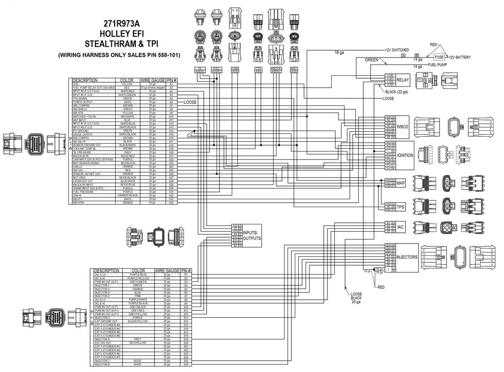
24 APPENDIX 1.0 Pinout The following shows pins that are used on Avenger systems. Pins that are not used on Avenger systems, but may have wires populated in the harness, are denoted with an asterisk (*). P1A Connector P1B Connector Pin Function Pin Function A1 Coil Input B1 IAC A Lo A2 Fuel Pump Out (+12v) (10A Max) B2 IAC A Hi A3 * B3 Fan #2 Output (ground) A4 * B4 Injector F Output A5 TPS Input B5 Injector G Output A6 * B6 Injector H Output A7 WB1 COMPR2 B7 Injector E Output A8 WB1 Shield B8 IAC B Lo A9 WB HTR - B9 IAC B Hi A10 Switched +12v Input B10 Fan #1 Output (ground) A11 Manifold Air Temp Input B11 * A12 * B12 A/C Shutdown (+12v) A13 * B13 Injector D Output A14 Cam/Crank Ground B14 * A15 Gauge Digital Output B15 * A16 WB1 COMPR1 B16 * A17 WB1 VS-/IP+ B17 * A18 Sensor Ground B18 * A19 Engine Coolant Temp Input B19 Injector A Output A20 Oil Pressure Input B20 EST 12V Output A21 * B21 * A22 Cam Sync Input / Ignition Bypass Output B22 * A23 Map Sensor Input B23 * A24 CAN Lo B24 * A25 WB1 VS+ B25 Injector C Output A26 Sensor +5v B26 Injector B Output A27 NOT USED A28 EST/Spout Output A29 * A30 Crank Speed Input A31 Fuel Pressure Input A32 CAN Hi A33 WB1 IP+ A34 WB HTR + 199R10554 wf Date: Holley Performance Products 1801 Russellville Road Bowling Green, KY Technical Service: Fax: For online help, please refer to the Technical Information section of our website:
25
AVENGER EFI 4 BBL MPFI SYSTEMS
 AVENGER EFI 4 BBL MPFI SYSTEMS SINGLE PLANE 4BBL SMALL BLOCK CHEVY MULTI-PORT EFI SYSTEMS 550-811 (Early/Late Models) 550-816 (Vortec Heads) SINGLE PLANE 4BBL BIG BLOCK CHEVY MULTI-PORT EFI SYSTEMS 550-831
POWER PACK 4 BBL MPFI SYSTEMS
 POWER PACK 4 BBL MPFI SYSTEMS SINGLE PLANE 4BBL SMALL BLOCK CHEVY POWER PACK SYSTEMS 550-700 (Early/Late Models) 550-701 (Vortec Heads) SINGLE PLANE 4BBL BIG BLOCK CHEVY POWER PACK SYSTEMS 550-702 (Std
StealthRam Small Block Chevy Multi-Port EFI Systems Standard and Vortec Intake Versions
 StealthRam Small Block Chevy Multi-Port EFI Systems Standard and Vortec Intake Versions 550-820 (Early/Late Heads) 550-823 (Early/Late Heads) Polished 550-828 (Vortec Heads) Polished NOTE: Fuel pump and
AVENGER EFI 4 BBL TBI SYSTEMS
 AVENGER EFI 4 BBL TBI SYSTEMS 550-400 (700 CFM 65 lb/hr injectors) up to 400 HP 550-401 (900 CFM 75 lb/hr injectors) up to 525 HP 550-402 (900 CFM 85 lb/hr injectors) up to 600 HP TBI HARDWARE INSTALLATION
FUEL KITS P/N & 526-4
 FUEL KITS P/N 526-3 & 526-4 NOTE: These instructions must be read and fully understood before beginning installation. If this manual is not fully understood, installation should not be attempted. Failure
FUEL KITS P/N & 526-2
 FUEL KITS P/N 526-1 & 526-2 NOTE: These instructions must be read and fully understood before beginning installation. If this manual is not fully understood, installation should not be attempted. Failure
EFI HARNESS KIT , & Kit Contents: Power Harness : All Kits
 EFI HARNESS KIT 558-500, 558-501 & 558-502 Kit Contents: Main Harness 558-102: Kits 558-500 558-103: Kits 558-501 & 502 Power Harness 558-308: All Kits Injector Harness 558-200: Kits 558-500 & 502 558-201:
Sniper EFI Fuel Kits P/N 526-5/526-8 (20 ft. hose) & (40 ft. hose)
 & (40 ft. hose)") Sniper EFI Fuel Kits P/N 526-5/526-8 (20 ft. hose) & 526-7 (40 ft. hose) 1.0 FUEL SYSTEM INSTALLATION DANGER! Take precautions to ensure that all fuel components are away from heat sources, such as the
Sniper EFI Fuel Kits P/N 526-5/526-8 (20 ft. hose) & 526-7 (40 ft. hose) 1.0 FUEL SYSTEM INSTALLATION DANGER! Take precautions to ensure that all fuel components are away from heat sources, such as the
HP EFI 4 BBL TBI SYSTEMS
 HP EFI 4 BBL TBI SYSTEMS 550-411 (900 CFM 75 lb/hr injectors) up to 525 HP 550-412 (900 CFM 85 lb/hr injectors) up to 600 HP NOTE: HP throttle body systems do not include fuel pump. TBI HARDWARE INSTALLATION
4 BBL THROTTLE BODY FUEL INJECTION SYSTEM
 4 BBL THROTTLE BODY FUEL INJECTION SYSTEM 550-405 950 CFM 200-600 HP Polished Aluminum 550-406 950 CFM 200-600 HP Hard Core Gray INSTALLATION MANUAL 199R10653 NOTE: These instructions must be read and
INSTALLATION TUNING AND TROUBLESHOOTING MANUAL
 Part Number 501-12 Pro-Jection 1D, 300 CFM INSTALLATION TUNING AND TROUBLESHOOTING MANUAL These instructions must be read and fully understood before beginning installation. If this manual is not fully
ELECTRIC FUEL PUMPS P/N , , & FUEL PRESSURE REGULATOR P/N
 ELECTRIC FUEL PUMPS P/N 80000100, 80000101, & 80000102 FUEL PRESSURE REGULATOR P/N 80000103 Installation Instructions 199R10583 These instructions must be read and fully understood before beginning the
Not required for most applications. Not required for most applications. High pressure ( provided) High pressure ( provided)
 High pressure ( provided)") ELECTRIC FUEL PUMPS P/N 12-801-1, 712-801-1, 12-802-1, 12-802-2, 712-802-1, 12-812, 12-815-1, & 712-815-1 FUEL PRESSURE REGULATORS P/N 12-500, 12-501, 12-803, 12-803BP, 12-804, & 15812NOS Installation
ELECTRIC FUEL PUMPS P/N 12-801-1, 712-801-1, 12-802-1, 12-802-2, 712-802-1, 12-812, 12-815-1, & 712-815-1 FUEL PRESSURE REGULATORS P/N 12-500, 12-501, 12-803, 12-803BP, 12-804, & 15812NOS Installation
WEIAND STREET WARRIOR INTAKE MANIFOLD P/N s 8125, 8125P, 8126, & 8126P SMALL BLOCK CHEVROLET
 APPLICATIONS: WEIAND STREET WARRIOR INTAKE MANIFOLD P/N s 8125, 8125P, 8126, & 8126P 262-400 SMALL BLOCK CHEVROLET INSTALLATION INSTRUCTIONS The P/N 8125 & 8126 WEIAND STREET WARRIOR series intake manifolds
BEFORE BEGINNING INSTALLATION
 COMPLETE CHASSIS FUEL LINE KITS For 1996-2000 Honda Civic Equipped with B-Series Engine INSTALLATION INSTRUCTIONS PLEASE study these instructions carefully before beginning this installation. Most installations
Installation Instructions
 Installation Instructions for 15912 to 15916 Electric Fuel Pumps & Fuel Pressure Regulators Installation Instructions WARNING! These instructions must be read and fully understood before beginning the
HP EFI UNIVERSAL RETROFIT KITS
 HP EFI UNIVERSAL RETROFIT KITS 550-500 (HP Universal Retrofit Kit for 4150 carb style intakes) 550-501 (HP Universal Retrofit Kit for 4500 carb style intakes) INSTALLATION INSTRUCTIONS 199R10510 NOTE:
L Intake Manifold Part #
 86-93 5.0L Intake Manifold Part #5001-5002 I N S T A L L A T I O N I N S T R U C T I O N S Supplied Materials Bottom cover, Upper manifold, Lower manifold, Plenum cover plate, 1501 Throttle body (comes
BBK Intake Manifold Kit ( L) - Installation Instructions
 - Installation Instructions") BBK Intake Manifold Kit (86-93 5.0L) - Installation Instructions The below installation instructions work for the following products: BBK Intake Manifold Kit (86-93 5.0L) Please read through the instructions
BBK Intake Manifold Kit (86-93 5.0L) - Installation Instructions The below installation instructions work for the following products: BBK Intake Manifold Kit (86-93 5.0L) Please read through the instructions
4 BBL THROTTLE BODY FUEL INJECTION MASTER KIT
 4 BBL THROTTLE BODY FUEL INJECTION MASTER KIT 550-405K 950 CFM Polished Aluminum Throttle Body + Complete Fuel System 550-406K 950 CFM Hard Core Gray Throttle Body + Complete Fuel System FUEL INJECTION
Instruction Manual. Fuel Injection. for the following Go EFI Systems Go Street EFI System Easy-Street EFI System Kit Contents
 This Quick Start Manual is designed to get you up and running with the Go Street Kit and either the 40003 Fuel Command Center or the 40005 Inline Fuel Delivery Kit. The FiTech Go EFI System is the industry's
DOMINATOR FUEL PUMPS P/N & Installation Instructions 199R10573
 DOMINATOR FUEL PUMPS P/N 12-1400 & 12-1800 Installation Instructions 199R10573 WARNING! THESE INSTRUCTIONS MUST BE READ AND FULLY UNDERSTOOD BEFORE BEGINNING INSTALLATION. FAILURE TO FOLLOW THESE INSTRUCTIONS
KIT CONTENTS. Multimeter or test light Wire crimpers or soldering equipment. Wire terminals & connectors 10A inline fuse
 RUSSELL FORD 5.0L COMPLETE EFI PLUMBING KIT INSTALLATION INSTRUCTIONS Please study these instructions carefully before installing your new complete fuel system kit. If you have any questions, please call
CAUTIONS AND WARNINGS
 FIREWALL FORWARD FUEL LINE KITS For 1996-2000 Honda Civic Equipped with B-Series Engine INSTALLATION INSTRUCTIONS PLEASE study these instructions carefully before beginning this installation. Most installations
HP FUEL PUMPS P/N & Installation Instructions 199R10569
 HP FUEL PUMPS P/N 12-700 & 12-890 Installation Instructions 199R10569 WARNING! THESE INSTRUCTIONS MUST BE READ AND FULLY UNDERSTOOD BEFORE BEGINNING INSTALLATION. FAILURE TO FOLLOW THESE INSTRUCTIONS MAY
INSTALLATION, TUNING, AND TROUBLESHOOTING MANUAL
 MARINE Part Number 700-21 For V-8 Engines 2D INSTALLATION, TUNING, AND TROUBLESHOOTING MANUAL NOTE: These instructions must be read and fully understood before beginning installation. If this manual is
EDELBROCK THUNDER SERIES AVS CARBURETORS Part #1801, 1802, 1803, 1804, 1805, 1806, 1812, 1813, 1825, 1826 INSTALLATION INSTRUCTIONS
 EDELBROCK THUNDER SERIES AVS CARBURETORS Part #1801, 1802, 1803, 1804, 1805, 1806, 1812, 1813, 1825, 1826 INSTALLATION INSTRUCTIONS IMPORTANT NOTE: Proper installation is the responsibility of the installer.
Holley High Performance Intake System* For Port 13B Engines (Includes B 6-Port engines converted to 4-Port)
") Holley High Performance Intake System* For 1974-1978 4-Port 13B Engines (Includes 1984-85 13B 6-Port engines converted to 4-Port) Installation Instructions I-18038 Note: These instructions assume: The
Holley High Performance Intake System* For 1974-1978 4-Port 13B Engines (Includes 1984-85 13B 6-Port engines converted to 4-Port) Installation Instructions I-18038 Note: These instructions assume: The
WIRING MANUAL & DIAGRAMS 199R10555
 WIRING MANUAL & DIAGRAMS 199R10555 HP EFI and Dominator EFI Systems Contents 1.0 Manual Overview... 2 1 1.1 Important Wiring Do s and Don ts... 3 2.0 ECU Installation, Connectors, and Pinout... 3 2.1 Pinout...
FREE $15 Gift Card for every $100 spent on Ship To Home orders. Find Out How
 1 of 29 10/12/2011 5:05 PM FREE $15 Gift Card for every $100 spent on Ship To Home orders. Find Out How Ford Ranger/Explorer/Mountaineer 1991-1999 Intake Manifold REMOVAL & INSTALLATION Print The engines
Holley GM BBC Single-Plane EFI Intake Manifold Kits
 Holley GM BBC Single-Plane EFI Intake Manifold Kits 300-561 Oval Port, 4150 Flange 300-562 Oval Port, 4500 Flange 300-563 Rectangular Port, 4150 Flange 300-564 Rectangular Port, 4500 Flange INSTALLATION
HP FUEL PUMPS P/N ERL & ERL Installation Instructions 199R11108
 HP FUEL PUMPS P/N 1200600ERL & 1200890ERL Installation Instructions 199R11108 WARNING! THESE INSTRUCTIONS MUST BE READ AND FULLY UNDERSTOOD BEFORE BEGINNING INSTALLATION. FAILURE TO FOLLOW THESE INSTRUCTIONS
Installation Instructions
 CHEVROLET ENGINE SYSTEM, NON-EMISSION 1967-1987 SMALL BLOCK CHEVROLET Part Number 300-502 CHEVROLET ENGINE SYSTEM, NON-EMISSION 1962-1987 CHEVROLET 302, 327, 350 C.I.D. ENGINES Part Number 300-503-1 Installation
EDELBROCK THUNDER SERIES AVS CARBURETORS Part #1801, 1802, 1803, 1804, 1805, 1806, 1812, 1813, 1825, 1826 INSTALLATION INSTRUCTIONS
 EDELBROCK THUNDER SERIES AVS CARBURETORS Part #1801, 1802, 1803, 1804, 1805, 1806, 1812, 1813, 1825, 1826 INSTALLATION INSTRUCTIONS PLEASE study these instructions carefully before beginning this installation.
Quadrajet Sniper EFI ( Shiny, Black, & Gold)
") Quadrajet Sniper EFI (550-867 Shiny, 550-868 Black, & 550-869 Gold) 1 Holley Sniper EFI FUEL INJECTION INSTALLATION MANUAL WARNING! Read this manual before using this product. This instruction manual must
Quadrajet Sniper EFI (550-867 Shiny, 550-868 Black, & 550-869 Gold) 1 Holley Sniper EFI FUEL INJECTION INSTALLATION MANUAL WARNING! Read this manual before using this product. This instruction manual must
UNIVERSAL PUMP HANGER INSTALLATION INSTRUCTIONS
 UNIVERSAL PUMP HANGER INSTALLATION INSTRUCTIONS WARNING! THESE INSTRUCTIONS MUST BE READ AND FULLY UNDERSTOOD BEFORE BEGINNING INSTALLATION. FAILURE TO FOLLOW THESE INSTRUCTIONS MAY RESULT IN POOR PERFORMANCE,
Operating and Installation Instructions
 Model Number 40401-c (-sp) Electronic Fuel Pump Operating and Installation Instructions This Product is Patent Pending. Application available upon request CAUTION! This product is to be installed only
SLP Camaro ZL1 STAGE 3 (650 HP)
") SLP - 2012 Camaro ZL1 STAGE 3 (650 HP) PART #26002 PACKING LIST Before installation, use this check list to make sure all necessary parts have been included. ITEM QTY CHECK PART NUMBER DESCRIPTION 1. 1
SLP - 2012 Camaro ZL1 STAGE 3 (650 HP) PART #26002 PACKING LIST Before installation, use this check list to make sure all necessary parts have been included. ITEM QTY CHECK PART NUMBER DESCRIPTION 1. 1
WEIAND INTAKE MANIFOLD P/N 7550 SMALL BLOCK CHEVROLET 3x2 BBL
 WEIAND INTAKE MANIFOLD P/N 7550 SMALL BLOCK CHEVROLET 3x2 BBL INTAKE MANIFOLD INSTALLATION INSTRUCTIONS 199R10703 APPLICATIONS: The P/N 7550 WEIAND intake manifold is designed for Holley 3x2 BBL, model
WEIAND X-CELerator Intake Manifold P/N 7516
 WEIAND X-CELerator Intake Manifold P/N 7516 351C FORD, 2V CYLINDER HEADS INSTALLATION INSTRUCTIONS APPLICATIONS: The P/N 7516 X-CELerator intake manifold is designed for square-bore carburetor applications
Edelbrock E-Force RPM Carburetor Supercharger C.I.D. Small-Block Chevy
 Edelbrock E-Force RPM Carburetor Supercharger 302-400 C.I.D. Small-Block Chevy 1986 and Earlier Style Heads: 1513, 1514, 15131, 15133, 15141, 15143 E-Tec and Vortec Style Heads: 1515, 1516, 15151, 15153,
UNIVERSAL PUMP HANGER INSTALLATION INSTRUCTIONS
 UNIVERSAL PUMP HANGER INSTALLATION INSTRUCTIONS WARNING! THESE INSTRUCTIONS MUST BE READ AND FULLY UNDERSTOOD BEFORE BEGINNING INSTALLATION. FAILURE TO FOLLOW THESE INSTRUCTIONS MAY RESULT IN POOR PERFORMANCE,
Fuel Injection. Instruction Manual
 FiTech TM Fuel Injection Instruction Manual for the following Go EFI Systems 30001, 30002, 30004, 30012, 30061, 30062 & 30064 This Quick Start Manual is designed to get you up and running with the Go EFI
DESCRIPTION MECHANICAL FUEL PUMP FUEL FILTER HIGH PRESSURE (35-90 PSI) HIGH PRESSURE (35-90 PSI) (STEEL/INCLUDED)
 HIGH PRESSURE (35-90 PSI) (STEEL/INCLUDED)") Edelbrock EFI Universal Fuel Sump System - Adjustable Part #36031, 36032, 36033, 36034 INSTALLATION INSTRUCTIONS PLEASE study these instructions carefully before beginning this installation. This installation
Edelbrock EFI Universal Fuel Sump System - Adjustable Part #36031, 36032, 36033, 36034 INSTALLATION INSTRUCTIONS PLEASE study these instructions carefully before beginning this installation. This installation
Pre-Installed. 1 Seal Kit 10 Silicone O-ring, 3/32 W, Intake Port Seals 1 Throttle Body Seal
 Atomic AirForce Intake Manifold for LS7, 2006-2013 Corvette and 2014 Z28 Camaro - PN 2701 LS2, 2005-2007 Corvette and CTS-V, 2005-2006 GTO and SSR PN 2702 LS1/6*, 1997-2004 Corvette, 1998-2002 Camaro/Firebird,
Weistec M113K Supercharger System Installation Guide
 Weistec M113K Supercharger System Installation Guide WARNING! DO NOT HAVE YOUR ECU REPROGRAMMED ANYWHERE BUT AT WEISTEC FOR THIS SUPERCHARGER. THE AMG 55 USES AN ELECTRONIC THROTTLE CONTROL (ETC), WHICH
MPFI FUEL INJECTION SYSTEM
 MPFI FUEL INJECTION SYSTEM PART NUMBERS 550-608 thru 550-615, 550-622 & 550-623 INSTALLATION & TUNING MANUAL 199R10762 NOTE: These instructions must be read and fully understood before beginning installation.
Fuel Delivery Requirements
 held Controller the Go EFI System creates a base fuel MAP to get the engine running. Then the self tuning programming will fine tune the MAP to produce optimum power and performance. Through the use of
Edelbrock EFI Universal Fuel Sump System - Adjustable Part #36031, INSTALLATION INSTRUCTIONS
 Edelbrock EFI Universal Fuel Sump System - Adjustable Part #36031, 36032 INSTALLATION INSTRUCTIONS PLEASE study these instructions carefully before beginning this installation. This installation can be
4150 Sniper EFI ( Shiny, Black, & Gold)
") 4150 Sniper EFI (550-510 Shiny, 550-511 Black, & 550-516 Gold) 1 Holley Sniper EFI FUEL INJECTION INSTALLATION MANUAL WARNING! Read this manual before using this product. This instruction manual must be
4150 Sniper EFI (550-510 Shiny, 550-511 Black, & 550-516 Gold) 1 Holley Sniper EFI FUEL INJECTION INSTALLATION MANUAL WARNING! Read this manual before using this product. This instruction manual must be
PIMP Ford 5.0 Harness Installation Manual. Part Number: PM-75
 PIMP Ford 5.0 Harness Installation Manual Part Number: PM-75 Ron Francis Wiring 200 Keystone Rd Suite 1 Chester, PA 19013 800-292-1940 www.ronfrancis.com Pre-Installation Notes: This system is designed
1988 Ford F-350 PICKUP
 1988 Ford F-350 PICKUP Submodel: Engine Type: V8 Liters: 7.5 Fuel Delivery: FI Fuel: GAS 1987 93 4.9L Engine The intake and exhaust manifolds on these engines are known as combination manifolds and are
HOWELL INSTALLATION MANUAL. Throttle Body Fuel Injection Harness
 HOWELL ENGINE DEVELOPMENTS, INC. FUEL INJECTION APPLICATIONS INSTALLATION MANUAL Throttle Body Fuel Injection Harness Howell Engine Developments, Inc. 6201 Industrial Way Marine City, MI 48039 Phone: 810-765-5100
Stratified Aux fuel system ecoboost 2.0
 Stratified Aux fuel system ecoboost 2.0 Additional Fuel Injection System Installation and User Guide Stratified Aux Fuel System Installation and User Guide -1-0204-0021.1 Thank you and congratulations
HOWELL INSTALLATION MANUAL. Tuned Port Or LT-1 Fuel Injection Harness ( )
") HOWELL ENGINE DEVELOPMENTS, INC. FUEL INJECTION APPLICATIONS INSTALLATION MANUAL Tuned Port Or LT-1 Fuel Injection Harness (1985-1992) Howell Engine Developments, Inc. 6201 Industrial Way Marine City,
HOWELL ENGINE DEVELOPMENTS, INC. FUEL INJECTION APPLICATIONS INSTALLATION MANUAL Tuned Port Or LT-1 Fuel Injection Harness (1985-1992) Howell Engine Developments, Inc. 6201 Industrial Way Marine City,
GENERAL INSTRUCTIONS. PERFORMER-PLUS CAMSHAFT / LIFTERS / LUBE KIT MODEL: c.i.d. Chevrolet V8 Engines CATALOG #2117
 Page 1 PERFORMER-PLUS CAMSHAFT / LIFTERS / LUBE KIT MODEL: 283-400 c.i.d. Chevrolet V8 Engines GENERAL INSTRUCTIONS PLEASE study these instructions carefully before beginning this installation. Most installations
Ford Racing Performance Improvement Intake Manifold (96-04 GT) Time Necessary: Approximately 4 hours
 Time Necessary: Approximately 4 hours") Ford Racing Performance Improvement Intake Manifold (96-04 GT) Time Necessary: Approximately 4 hours Tools Required: Ratchet and socket set Torque wrench Large adjustable wrench Needle nose pliers A dozen
Ford Racing Performance Improvement Intake Manifold (96-04 GT) Time Necessary: Approximately 4 hours Tools Required: Ratchet and socket set Torque wrench Large adjustable wrench Needle nose pliers A dozen
ZX-14 Stage I Turbo Kit
 62910 Peerless Ct. Bend, OR 97701 Phone 541.385.0706 Fax 541.382.9406 ZX-14 Stage I Turbo Kit WARNING: This turbo kit is for OFF-ROAD RACING use ONLY. Advisement: These instructions are written to be comprehensive
PERFORMER-PLUS CAMSHAFT / LIFTERS / LUBE KIT CATALOG # 2103 MODEL: 400 c.i.d. Chevrolet V8 engines GENERAL INSTRUCTIONS
 PERFORMER-PLUS CAMSHAFT / LIFTERS / LUBE KIT CATALOG # 2103 MODEL: 400 c.i.d. Chevrolet V8 engines GENERAL INSTRUCTIONS Please study these instructions carefully before you remove your stock camshaft.
On all settings above 100 horsepower the following precautions should be observed:
 ELECTRONIC FUEL INJECTED 5.0 COYOTE PLATE SYSTEM INSTALLATION INSTRUCTIONS Congratulations on the purchase of your Nitrous Express Coyote Plate system. Nitrous Express utilizes only the highest quality
Summit Racing MAX-efi500
 Not legal for sale or use on pollution controlled vehicles Installation and Adjustment Instructions for Summit Racing MAX-efi500 Throttle Body System P/N SUM-240500 Please read the full instructions before
QUICKSTART MANUAL SNIPER EFI INSTALLATION INSTRUCTIONS
 550-510, 550-511, & 550-516 QUICKSTART MANUAL SNIPER EFI INSTALLATION INSTRUCTIONS Congratulations on your purchase of a new Sniper EFI Throttle Body System built by craftsmen to exacting standards in
Front Drive System - Big Block Chevy Installation Instructions Big Block Chevy with AC & with PS
 Front Drive System - Big Block Chevy Installation Instructions Big Block Chevy with AC & with PS All American Billet Store (800) 764-0926 www.allamericanbilletstore.com Items needed for install Jack Jack
Installation Instructions General Motors 8.1 Sequential Vapor Injection (S.V.I.) System 7500/6500 Series Trucks model year.
 System 7500/6500 Series Trucks model year.") Installation Instructions General Motors 8.1 Sequential Vapor Injection (S.V.I.) System 7500/6500 Series Trucks 2003-2005 model year. Technocarb Equipment (2004) Ltd. 4-30435 Progressive Way Abbotsford,
Installation Instructions General Motors 8.1 Sequential Vapor Injection (S.V.I.) System 7500/6500 Series Trucks 2003-2005 model year. Technocarb Equipment (2004) Ltd. 4-30435 Progressive Way Abbotsford,
255 Liter/Hr, In Tank Fuel Pump For Chrysler Front Wheel Drive Vehicles Catalog # INSTALLATION INSTRUCTIONS
 255 Liter/Hr, In Tank Fuel Pump For 1984-1990 Chrysler Front Wheel Drive Vehicles Catalog # 17934 INSTALLATION INSTRUCTIONS PLEASE study these instructions carefully before installing your new In-Tank
M-9424-M50CJ INTAKE MANIFOLD INSTALLATION INSTRUCTIONS
 Please visit www.fordracingparts.com for the most current instruction information!!! PLEASE READ ALL OF THE FOLLOWING INSTRUCTIONS CAREFULLY PRIOR TO INSTALLATION. AT ANY TIME YOU DO NOT UNDERSTAND THE
Installation Instructions for Chevrolet C5 Corvette Lingenfelter High Flow Fuel Pump Module
 Installation Instructions for 1997-2003 Chevrolet C5 Corvette Lingenfelter High Flow Fuel Pump Module PN: L710650197 Lingenfelter Performance Engineering 1557 Winchester Road Decatur, IN 46733 (260) 724-2552
MODEL NUMBER: MEDIUM DUTY ONBOARD AIR SYSTEM
 MODEL NUMBER: 10003 MEDIUM DUTY ONBOARD AIR SYSTEM IMPORTANT: It is essential that you and any other operator of this product read and understand the contents of this manual before installing and using
INSTALLATION INSTRUCTIONS
 28 INSTALLATION INSTRUCTIONS SECTION - AIR SPRING SECTION 2 - AIR ACCESSORY 2-5 ! IMPORTANT PLEASE DON T HURT YOURSELF, YOUR KIT OR YOUR VEHICLE. TAKE A MINUTE TO READ THIS IMPORTANT INFORMATION. This
Edelbrock E-Force RPM Carburetor Supercharger Chevrolet LS Engines
 Carburetors and air cleaner sold separately. Edelbrock E-Force RPM Carburetor Supercharger Chevrolet LS Engines Rectangular Port Heads: 1511, 15111, 15113 Cathedral Port Heads: 1512, 15121, 15123 Page
Edelbrock Enforcer EFI Supercharger C.I.D. Small-Block Chevy
 Photo may not represent actual product. 302-400 C.I.D. Small-Block Chevy 1986 and Earlier Style Heads: 1520, 1521, 15201, 15211, 15203, 15213 E-Tec and Vortec Style Heads: 1522, 1523, 15221, 15231, 15223,
Carb2EFI Fuel System Conversion Kit Intank Fuel Pump (450 LPH Gasoline/E85 Compatible)
") Carb2EFI Fuel System Conversion Kit Intank Fuel Pump (450 LPH Gasoline/E85 Compatible) Thanks for your purchase of this kit. We have worked hard to provide kits that contain exactly what you need No more
Carb2EFI Fuel System Conversion Kit Intank Fuel Pump (450 LPH Gasoline/E85 Compatible) Thanks for your purchase of this kit. We have worked hard to provide kits that contain exactly what you need No more
INTRODUCTION E-STREET SOFTWARE UPDATES IMPORTANT WARNINGS
 INTRODUCTION Thank you for selecting the Edelbrock E-Street 2 EFI system. This is a universal, throttle body style, electronic fuel injection system, intended for most V8 engines originally equipped with
LSX Intake Manifold. #54001 LSX (78mm Throttle Body) #54003 LSX (90mm Throttle Body)
 #54003 LSX (90mm Throttle Body)") LSX Intake Manifold #54001 LSX (78mm Throttle Body) #54003 LSX (90mm Throttle Body) Thank you for your purchase of the most innovative and powerful Gen III (LS1 and LS6) manifold ever developed. We are
LSX Intake Manifold #54001 LSX (78mm Throttle Body) #54003 LSX (90mm Throttle Body) Thank you for your purchase of the most innovative and powerful Gen III (LS1 and LS6) manifold ever developed. We are
REMOVAL. Fig Sized for Print
 ALLDATA Online - 2000 Dodge Truck Grand Caravan FWD V6-3.3L VIN R - Intake M... Page 1 of 10 REMOVAL 1. Remove windshield wiper module. 2. Perform fuel system pressure release procedure (before attempting
M V Intake Manifold INSTRUCTION SHEET
 Please visit www.fordracingparts.com for the most current instruction information.!!! PLEASE READ ALL OF THE FOLLOWING INSTRUCTIONS CAREFULLY PRIOR TO INSTALLATION. AT ANY TIME YOU DO NOT UNDERSTAND THE
QUICK FUEL TECHNOLOGY HOT ROD SERIES CARBURETORS SLAYER SERIES CARBURETORS SUPER STREET SERIES CARBURETORS
 QUICK FUEL TECHNOLOGY Installation Instructions HOT ROD SERIES CARBURETORS SLAYER SERIES CARBURETORS SUPER STREET SERIES CARBURETORS HR-580-VS 580 CFM Vac. Secondary!!! SS-680-VS 680 CFM Vac. Secondary
Lower Intake Manifold Replacement
 Lower Intake Manifold Replacement Removal Procedure 1. Turn OFF all the lamps and the accessories. 2. Ensure the ignition switch is in the OFF position. 3. Disconnect the negative battery cable from the
Procharger Stage II Intercooled Supercharger System (11-14 GT)
") Procharger Stage II Intercooled Supercharger System (11-14 GT) Installation Time: Approximately one day. Installed on 2012 Mustang GT 5.0/Manual Required Tools 3/8 Socket Set (Standard and Metric) 1/2
Procharger Stage II Intercooled Supercharger System (11-14 GT) Installation Time: Approximately one day. Installed on 2012 Mustang GT 5.0/Manual Required Tools 3/8 Socket Set (Standard and Metric) 1/2
EXHAUST SYSTEM AND INTAKE MANIFOLD
 EXHAUST SYSTEM AND INTAKE MANIFOLD 11-1 EXHAUST SYSTEM AND INTAKE MANIFOLD CONTENTS page GENERAL INFORMATION... 1 SERVICE PROCEDURES... 4 page TORQUE SPECIFICATION... 13 EXHAUST SYSTEMS The exhaust systems
BEFORE BEGINNING INSTALLATION
 EDELBROCK E-FORCE SUPERCHARGER KITS Catalog #1551, 15511, 1552, 15521, 1553, 15531, 1554, 15541, 15611, 15621, 15631, 15641 INSTALLATION INSTRUCTIONS PLEASE study these instructions carefully before beginning
4. Remove distributor hold-down. Lift the distributor upwards and remove.
 Holley Sniper EFI HyperSpark Distributors are designed to plug and play with Sniper EFI systems. This design includes a single Hall Effect sensor providing crankshaft speed to the ECU. The precision machined
FUEL SYSTEM PRECAUTION FU 1
 2GR-FE EL EL SYSTEM EL SYSTEM PRECAUTION 1 1. EXPRESSIONS OF IGNITION SWITCH (a) The type of the ignition switch used on this model differs according to the specifications of the vehicle. The expressions
Ford 6.7 EGR Delete Kit
 Fits: 2011 12 Powerstroke 6.7L Read instructions thoroughly before proceeding! ***This kit may void factory warranty please check with manufacturer.*** ***This kit is intended for off road use only.***
MALLORY FIRESTORM CD MULTI COIL HARDWARE INSTALLATION - PN 69150C / 69150R
 FORM 69150C/R MALLORY FIRESTORM CD MULTI COIL HARDWARE INSTALLATION - PN 69150C / 69150R To ensure you are using the most current instruction sheet, please visit www.malloryfirestorm.com. CAUTION! The
HOLLEY VR2 FUEL PUMPS P/N & Installation Instructions 199R10975
 HOLLEY VR2 FUEL PUMPS P/N 12-3000 & 12-3000-2 Installation Instructions 199R10975 WARNING! THESE INSTRUCTIONS MUST BE READ AND FULLY UNDERSTOOD BEFORE BEGINNING INSTALLATION. FAILURE TO FOLLOW THESE INSTRUCTIONS
2006 Honda Civic SI Supercharger Kit Installation Instruction Kit #
 2006 Honda Civic SI Supercharger Kit Installation Instruction Kit #350-091 3239 MONIER CIRCLE, STE.5 RANCHO CORDOVA, CA 95742 916.635.4550 FAX 916.635.4632 www.ct-engineering.com INS-157 VERSION: 3.25.2009
MALLORY FIRESTORM CD MULTI COIL HARDWARE INSTALLATION - PN 69050S / 69050R
 FORM 69050S/R MALLORY FIRESTORM CD MULTI COIL HARDWARE INSTALLATION - PN 69050S / 69050R To ensure you are using the most current instruction sheet, please visit www.malloryfirestorm.com. CAUTION! The
AEROMOTIVE Part # HP Hot Rod EFI Kit INSTALLATION INSTRUCTIONS
 AEROMOTIVE Part # 17150 700HP Hot Rod EFI Kit INSTALLATION INSTRUCTIONS CAUTION: Installation of this product requires detailed knowledge of automotive systems and repair procedures. We recommend that
Chevy Truck
 Classic Instruments 1973 1987 Chevy Truck Installation Manual Table of Contents Welcome from the Team at Classic Instruments!... 3 Gauge Mounting... 4 Gauge Cluster Wiring... 6 Pulse Signal Generator [SN16]
Holley LS Modular Mid-Rise Intake Manifold Kits and Mid-Rise Plenum Base Adapter for Custom EFI Intake Manifold Installations
 Holley LS Modular Mid-Rise Intake Manifold Kits and Mid-Rise Plenum Base Adapter for Custom EFI Intake Manifold Installations Holley P/N Description 300-126 / 300-126BK LS1 Modular Mid-Rise Intake Manifold
Single Nozzle Systems UNIVERSAL NOZZLE SYSTEM INSTRUCTIONS Part #'S 00-1XXXXX
 INTRODUCTION Thank you for purchasing the highest quality nitrous system on the market. Nitrous Outlet strives to offer the best product with the best price and customer service available. Nitrous Outlet
Performer-Plus 5.0L Hydraulic Roller Lifter Camshaft only CATALOG #3722 MODEL: 5.0 Litre Ford V8, 1985 & later INSTRUCTIONS
 Performer-Plus 5.0L Hydraulic Roller Lifter Camshaft only CATALOG #3722 MODEL: 5.0 Litre Ford V8, 1985 & later INSTRUCTIONS PLEASE study these instructions carefully before installing your new camshaft.
8 Injector 4150 Super Sniper EFI ( Shiny, Black, & Gold) 4 Injector 4150 Super Sniper EFI ( Shiny, Black, &
 4 Injector 4150 Super Sniper EFI ( Shiny, Black, &") 8 Injector 4150 Super Sniper EFI (550-512 Shiny, 550-513 Black, & 550-517 Gold) 4 Injector 4150 Super Sniper EFI (550-518 Shiny, 550-519 Black, & 550-520 Gold) 1 Holley Sniper EFI FUEL INJECTION INSTALLATION
8 Injector 4150 Super Sniper EFI (550-512 Shiny, 550-513 Black, & 550-517 Gold) 4 Injector 4150 Super Sniper EFI (550-518 Shiny, 550-519 Black, & 550-520 Gold) 1 Holley Sniper EFI FUEL INJECTION INSTALLATION
AMS F1-I INTAKE MANIFOLD
 AMS F1-I INTAKE MANIFOLD The goal of AMS is to provide the highest quality, best performing products available. By utilizing research and development, and rigorous testing programs AMS will never compromise
2000 Chrysler SEBRING
 2000 Chrysler SEBRING Submodel: JX Engine Type: V6 Liters: 2.5 Fuel Delivery: FI Fuel: GAS 2.0L SOHC and 2.4L DOHC Engines The intake manifold for the 2.0L SOHC engine is a long branch design made of a
WARNING. Atomic AirForce Intake Manifold for
 Atomic AirForce Intake Manifold for LS7, 2006-2013 Corvette and 2014 Z28 Camaro - PN 2701 LS2, 2005-2007 Corvette and CTS-V, 2005-2006 GTO and SSR PN 2702 LS3/L99, 2008-2013 Corvette and 2010-2014 Camaro
9415 W. Ridge Rd. Elsie, MI
 9415 W. Ridge Rd. Elsie, MI 48831 248-393-1621 989-862-4163 TBI INSTALLATION INSTRUCTIONS Congratulations on the purchase of your Affordable Fuel Injection TBI system. We are confident that this purchase
WEBER CARBURETOR TROUBLESHOOTING GUIDE
 This guide is to help pinpoint problems by diagnosing engine symptoms associated with specific vehicle operating conditions. The chart will guide you step by step to help correct these problems. For successful
AEROMOTIVE Part # & Stealth Fuel Tank Sump INSTALLATION INSTRUCTIONS
 AEROMOTIVE Part # 18651 & 18652 Stealth Fuel Tank Sump INSTALLATION INSTRUCTIONS CAUTION: Installation of this product requires detailed knowledge of automotive systems and repair procedures. We recommend