Behotec C36, C36/2, C50 Retracts Instruction manual
|
|
|
- Blaze Miller
- 6 years ago
- Views:
Transcription
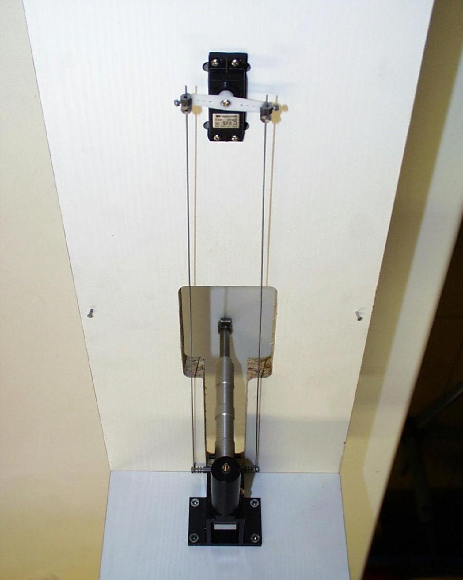
1 Behotec C36, C36/2, C50 Retracts Instruction manual Safety precaution Please handle these retract units with care. The retract actuators are operated by powerful cylinders. Instruction manual This manual is suitable to all Behotec retract systems. Air tank pressure does not need to be in excess of 100PSI (7bar). The maximum operating pressure of the tanks is 145PSI (10bar). Fill the tank using the supplied valve. The valve is equipped with a Festo fitting. Screw the valve onto the air tank (picture 18). Picture 1: Slide the 3mm air tube provided over the nipple. The left side fitting causes the retract strut to drop on C36-2 and C50 models, and the right side fitting retracts the strut. These nipple fittings ensure a very tight leak free hook-up. Be patient removing the tube and do not use a knife to cut through otherwise a leak might occur upon re-insertion of the air tube. Picture 2: The piston rod should stay clean and without scratches to avoid air loss. Picture 3: Use Loctite to fix the 6mm axle in the strut. Picture 4 and 19: Use the two worm screws to fix the brake calliper. Make sure there is enough clearance between the brass fitting and the strut when it is compressed. Use the 3x20mm worm screw to stop the brake calliper from rotating (picture 19). Picture 5: Assemble the two rims and rubber with the countersunk screws. Tighten the screws that are opposite to one another to ensure an even grip all around. Picture 6: Use the aluminium 5.5mm spacer sleeve between the rim and the brake calliper. Also refer to picture 20 and use a 3x16-20mm worm screw to fix the brake calliper to stop it from rotating.

.")
2 Picture 7: Slide the wheel over the axel and secure with collar. Picture 8: Attach the strut using the 6x40mm steel pin and secure with worm screws. Grinding a flat on the face of the steel pin ensures a tight and rotation free method of attachment. Picture 9: To assemble the front strut, use a 6mm brass axle, two spacers and screws. Ensure the wheel is positioned in the centre using two spacers. Picture 10 & 11: Use the same method to connect the nose wheel strut as you did for the main strut. However a 6x55mm steel pin is used along with two 5mm grub screws and black knuckle pins. Insert the steel pin in the retract unit and use the collar to stop it from sliding out (picture 11). Grinding a flat on the face of the steel pin ensure a tight and rotation free method of attachment. Picture 12: Use 4mm screw to enure the retract strut does not twist or turn. Grinding a flat on the face of the steel pin ensure a tight and rotation free method of attachment. Picture 13 & 14: You can use a pull-pull cable to turn the nose wheel. Use rubber bands or springs to pull the cable away during retraction. Picture 15-17: Here is another very simple way to turn the nose wheel. Please refer to picture for details. When the gear is retracted, this marks the end position of the rods where two collars are secured. picture 1 picture 2


3 picture 3 picture 4 picture 5 picture 6 picture 7 picture 8


4 picture 9 picture 10 picture 11 picture 12


5 picture 13 picture 14 picture 15 picture 16


6 picture 17 picture 18 picture 19
7 Lufteingang air in Fahrwerk eingefahren retract in Fahrwerk ausgefahren retract out Fahrwerk ausgefahren, Bremse aktiv retract out, brake in action Bremse / brake SPECIFICATIONS CONTRACT NO. COMPANY DRAWN BY CHECKED BY TITLE Behotec GmbH DESIGNED BY Schaltventil / Valve DESIGN ACTIVITY SIZE A4 FSCM NO. DWG NO. / FILE NAME CUSTOMER SCALE SHEET 1 m m = 1 m m 1 o f 1 Schlauch 4mm Tube 4mm Vent il/ Valve Fest o T/ Y- St ück 4/ 4/ 3 3mm Schlauch Tube 3mm SPECIFICATIONS CONTRACT NO. DRAWN BY CHECKED BY DESIGNED BY DESIGN ACTIVITY COMPANY TITLE SIZE A4 Behot ec C36/ 2 - C50 FSCM NO. DWG NO. / FILE NAME CUSTOMER SCALE SHEET 1 m m = 1 m m 1 o f 1
8 Schlauch 4mm Tube 4mm Vent il/ Valve Fest o T/ Y- St ück 4/ 4/ 3 3mm Schlauch Tube 3mm SPECIFICATIONS CONTRACT NO. DRAWN BY CHECKED BY DESIGNED BY DESIGN ACTIVITY COMPANY TITLE SIZE A4 Behot ec C36 FSCM NO. DWG NO. / FILE NAME CUSTOMER SCALE SHEET 1 m m = 1 m m 1 o f 1
Instruction Manual for HBK-D3 Chassis Kit
 Instruction Manual for HB-D3 Chassis it oundhouse Engineering Co. Ltd. Units 6-10 Churchill Business Park. Churchill oad, Wheatley. Doncaster. DN1 2TF. England. Tel. 01302 328035 mail@roundhouse-eng.com
FRP Ball Valves INSTALLATION & MAINTENANCE MANUAL
 FRP Ball Valves INSTALLATION & MAINTENANCE MANUAL FRP BALL VALVES TABLE OF CONTENTS MAINTENANCE AND INSTALLATION INSTRUCTIONS 1. 2. 2.1 2.2 2.3 2.4 GENERAL...Page 1 HANDLING...1 Receiving and Storing...1
AIRCRAFT LANDING GEAR CONSTRUCTION MANUAL
 APPENDIX AI KITPLANES FOR AFRICA AIRCRAFT LANDING GEAR CONSTRUCTION MANUAL Revision: C September 2008 Page L1 of 20 NOTE: Please read the General Manual before proceeding. Please read through the entire
VLW18TE, VLW18TI HYDRAULIC VERTICAL LIFTING WEDGES. Operator Instruction Manual INNOVATION IN ITS MOST FUNCTIONAL FORM
 VLW18TE, VLW18TI HYDRAULIC VERTICAL LIFTING WEDGES Operator Instruction Manual info@equalizerinternational.com www.equalizerinternational.com INNOVATION IN ITS MOST FUNCTIONAL FORM INDEX SECTION CONTENTS
CHAIN SAW PARTS CATALOG MODEL CS-6700 TYPE 1E SERIAL NUMBER & UP
 CHAIN SAW PARTS CATALOG MODEL CS-00 TYPE 1E SERIAL NUMBER 0001 & UP ECHO, INCORPORATED 400 OAKWOOD ROAD LAKE ZURICH, IL 004 999203008 0/03 CS-00 TYPE 1E ENGINE, CRANKCASE, CYLINDER, PISTON 20 1 2 38 39
Brake System H TX, H2.0TXS [B475]; H TX [B466] Safety Precautions Maintenance and Repair
![Brake System H TX, H2.0TXS [B475]; H TX [B466] Safety Precautions Maintenance and Repair](/thumbs/86/93834005.jpg "Brake System H TX, H2.0TXS [B475]; H TX [B466] Safety Precautions Maintenance and Repair") HMM180001 Brake System H1.5-1.8TX, H2.0TXS [B475]; H2.5-3.5TX [B466] Safety Precautions Maintenance and Repair When lifting parts or assemblies, make sure all slings, chains, or cables are correctly fastened,
HMM180001 Brake System H1.5-1.8TX, H2.0TXS [B475]; H2.5-3.5TX [B466] Safety Precautions Maintenance and Repair When lifting parts or assemblies, make sure all slings, chains, or cables are correctly fastened,
YOU MUST WEAR SAFETY GLASSES DURING EACH STEP OF THESE INSTRUCTIONS
 Machine Racer: Rally Preparation 1. Print the Working Drawing of the design you created and simulated in the Mousetrap Car 2.0 STEM Application. You can find your Working Drawing in the "Outputs" tab of
Printed from MediaCat
 Illustration A Crankcase Illustration A Crankcase Ref.Nr. Item code Quantity Description 1 1119 020 2118 1 Crankcase (1,3,5) 2-11 1 1119 020 2109 1 Crankcase (6,8,9) 2-11 1 1119 020 2119 1 Crankcase (2,4)
USER MANUAL. Pneumatic actuator - AL WARNING! WARNING! WARNING!
 Type and Design DA = Double Acting. Actuator with pneumatic operation in both directions. SR = Spring Return. Actuator with spring return. RC 210, 230, 250 and 270 have 1 piston. RC 220, 240, 260, 265
Brake Upgrades for FWD/4WD with 5x100 stud pattern
 Brake Upgrades for FWD/4WD with 5x100 stud pattern These started out as my original front brakes, & because I m more of a twisty road person, than straight line speed, I didn t think they d be adequate.
MANUAL. Pneumatic actuator - AL Type and Design. Operating Medium. The Application of the Scotch Yoke Construction WARNING!
 Ref. 5.400B_UK 20150511 www.axellarsson.se Pneumatic actuator AL 77200 Type and Design DA = Double Acting. Actuator with pneumatic operation in both directions. SR = Spring Return. Actuator with spring
Perfect Park 7000 Installation & Unloading Instructions Operating Manual
 Perfect Park 7000 Installation & Unloading Instructions Operating Manual 1) Always file a claim with the truck line if the lift has been damaged! (If you don t originally notice the damage, but find some
 www.pure-motorsport.co.uk 01841 531102 Renault Clio 172/182 front strut top mounts and strut brace. Top mount Overview. These front top mounts replace the standard rubber mounts. They improve the handling,
- BRONZE SERIES 30 - INSTALLATION MANUAL
 - BRONZE SERIES 30 - INSTALLATION MANUAL Thank you for purchasing our high quality retract system! We hope you will soon be experiencing the joy of flicking the retract switch with confidence and then
Printed from MediaCat
 Illustration A Crankcase Illustration A Crankcase Ref.Nr. Item code Quantity Description 1 1106 020 2506 1 Crankcase (2) 2-11 2 0000 988 5217 1 Connector (2) 3 0000 988 5200 2 Connector (2) 4 1106 641
Top quality for professionals. 1 aluminium truck
 Top quality for professionals 1 aluminium truck Modular aluminium truck The advantages at a glance Straight end of tubes with rocker enabling straightforward, convenient intervention even at high loads.
DB4604 GMR-SD and GMR40-SD Disc Brake Caliper - Spring Applied, Air Released
 DB464 GMR-SD and GMR4-SD Disc Brake Caliper - Spring Applied, Air Released Nominal dimensions given. For specific dimensions please contact Twiflex Limited. For GMR Mk 2 caliper details see DB 364 Air
JARVIS. Models USSS -1, USSS -2 and USSS -2A Pneumatic Stunners
 \ Models USSS -1, USSS -2 and USSS -2A Pneumatic Stunners Rear Handle for Knocker Box USSS--2A Side Handle for Knocker Box USSS--1 U.S. Patent No. 6,135,871 Patents Pending Worldwide Rear Handle for V
FRONT AXLE AND SUSPENSION FA 1
 FRONT AXLE AND SUSPENSION FA1 FRONT AXLE AND SUSPENSION FA2 FRONT AXLE AND SUSPENSION Troubleshooting TROUBLESHOOTING Problem Possible cause Remedy Page Wanders/pulls Tires worn or improperly inflated
PRODUCT SAFETY NOTICE
 PRODUCT SAFETY NOTICE Congratulations. This vehicle has been equipped with a Firestone air suspension system. This suspension will enhance the vehicle s handling when loaded, however, the vehicle s performance
Printed from MediaCat
 Illustration A Crankcase, Crankshaft Illustration A Crankcase, Crankshaft Ref.Nr. Item code Quantity Description 1 1117 020 2106 1 Crankcase 2-9 2 9022 341 1050 4 Spline screw IS-M5x25 3 0000 988 5211
4. SEPARATE SPEED SENSOR FRONT LH (a) Remove the bolt and disconnect the speed sensor wire and flexible hose from the shock absorber assy.
 Remove the bolt and disconnect the speed sensor wire and flexible hose from the shock absorber assy.") OVERHAUL Refer to components: See page 304 Use the same procedures for the RH side and LH side. The procedures listed below are for the LH side. 1. DRAIN TRANSAXLE OIL (a) Using a #10 socket hexagon wrench,
OVERHAUL Refer to components: See page 304 Use the same procedures for the RH side and LH side. The procedures listed below are for the LH side. 1. DRAIN TRANSAXLE OIL (a) Using a #10 socket hexagon wrench,
GMR-S and GMR40-S Disc Brake Caliper - Spring Applied, Air Released
 (GMR) 9 (GMR) ø GMR-S and GMR-S Disc Brake Caliper - Spring Applied, Air Released DB Nominal dimensions given. For specific dimensions please contact Twiflex Limited. For GMR Mk caliper details see DB
Bachmann GWR Earl (Dukedog) EM Finescale Conversion
 EM Finescale Conversion") Bachmann GWR Earl (Dukedog) EM Finescale Conversion Before you start, it is a good idea to have some small containers or snap top poly bags to put screws and components in for safe keeping...much better
Bachmann GWR Earl (Dukedog) EM Finescale Conversion Before you start, it is a good idea to have some small containers or snap top poly bags to put screws and components in for safe keeping...much better
Tools Required. Metric Wrench Set Screwdriver Set Metric Socket Set Pliers Heavy duty hydraulic Jack and Car Stands Box knife or similar Hacksaw WD40
 Subaru 2004+ Legacy GT & Outback XT For JDM 2.0 twinscroll turbo and USDM 2.5 turbo models Front Mount Intercooler Fitting Instructions PN# LEG-1348-000 You are now the proud owner of a highly tested and
ONYX VALVE CO MODEL CAR, CAP-PFO Installation & Maintenance
 ONYX VALVE CO MODEL CAR, CAP-PFO Installation & Maintenance OPERATION: (4-2010) The Onyx series CAR-PFO and CAP-PFO pinch valves fail open on loss of air. The simple spring and air bag arrangement drives
Included parts: 1 - New Bosch CP3 Pump 1 - HSM Pulley 1 - Serpentine Belt 1 - Pump Bracket/ Hardware STEP 1
 TROUBLESHOOTING: Please read and understand all installation instructions before proceeding with the installation. If you have questions during the installation of this product, please contact H&S Motorsports
Instructions for Assembling Driving Wheels, Axles and Crankpins
 Instructions for Assembling Driving Wheels, Axles and Crankpins (Version 1; October 2008) Introduction These instructions explain how to assemble Exactoscale 4mm scale driving wheels, axles and crankpins
Printed from MediaCat
 Illustration A Crankcase, Cylinder Illustration A Crankcase, Cylinder Ref.Nr. Item code Quantity Description 1 1113 020 2107 1 Crankcase (1,2,4,5,7,8) 2-11 1 1113 020 2108 1 Crankcase (3,6) 2-11 2 1113
KEROSINE FIRED MODEL STEAM TRACTION ENGINE CALLED "JULIAN"
 0........ DRAWING CONTENTS GENERAL ARRANGEMENT PROJECT No 0-0-00 J.A.M. DE WAAL. BRIGHTWELL STREET PAPAKURA. NEW ZEALAND. PHONE: OO 0. MOB: 000 JUNE-0 SHEET: 0 OF DWG SCALE: NTS @A OR AS SHOWN J.A.M. DE
Installation Guide Currie Electro-Drive Conversion Kits 2, 3, & 4
 Installation Guide Currie Electro-Drive Conversion Kits 2, 3, & 4 1 Before you start... Use this information to determine whether one of our kits will fit your bike Drawing Ref. Fork Area Leg clearance
6 S-10 Pickup/Jimmy/Blazer Torsion Bar Drop Kit
 92124300 6 S-10 Pickup/Jimmy/Blazer Torsion Bar Drop Kit Thank you for choosing Rough Country for all your suspension needs. Rough Country recommends a certified technician install this system. In addition
Type 2 Push-Through 37 Ton Log Splitter. Assembly Manual
 Type 2 Push-Through 37 Ton Log Splitter Assembly Manual Refer to this manual for the following models: RS37PT-LF09PC-16-1 RS37PT-LF09EC-16-1 RS37PT-LF09EC-16-2 RS37PT-LF13EC-22-1 RS37PT-LF13EC-22-2 RS37PT-LF15EC-22-1
INSTALLATION INSTRUCTIONS
 INSTALLATION INSTRUCTIONS --1075 North Ave. Sanger, CA 93657-3539 local: 559-875-8883 fax: 559-875-9883 toll free: 800-595-7016-- 90211 ST COILOVER GT BMW 3 Series E36 Sedan, Coupe, Convertible, Wagon
Sachs shock manual. ( ) 2 & 4 Stroke RR Enduro. ( ) RS Dual Sport
 2 & 4 Stroke RR Enduro. ( ) RS Dual Sport") Sachs shock manual (2013 2015) 2 & 4 Stroke RR Enduro (2014-2015) RS Dual Sport 1 Introduction The procedures in this manual must take place in a clean environment using professional tools and some specific,
Sachs shock manual (2013 2015) 2 & 4 Stroke RR Enduro (2014-2015) RS Dual Sport 1 Introduction The procedures in this manual must take place in a clean environment using professional tools and some specific,
'99-03 CHEVROLET/GMC IFS 4WD 6" SUSPENSION SYSTEM P/N INSTALLATION INSTRUCTIONS
 1/16/04 '99-03 CHEVROLET/GMC IFS 4WD 6" SUSPENSION SYSTEM P/N. 10-41099 INSTALLATION INSTRUCTIONS NOTE: Each Lift Kit and options to Lift Kits are packaged separately. Therefore, installation procedures
INSTALLATION INSTRUCTIONS for TIBUS Bolt-on Portals for Mercedes Benz G-wagon
 INSTALLATION INSTRUCTIONS for TIBUS Bolt-on Portals for Mercedes Benz G-wagon TIBUS Offroad Ltd. & Co. KG Roffhausener Landstrasse 25 26419 Schortens Germany Tel.: +49 (0) 4421 70 69 1 Fax: +49 (0) 4421
USER INSTRUCTIONS FOR OPERATION & MAINTENANCE 4068 Pneuma c / Hydraulic Installa on Tool
 Additional copies of this manual are available at: USER INSTRUCTIONS FOR OPERATION & MAINTENANCE 4068 Pneuma c / Hydraulic Installa on Tool 4068 Hydro-Pneumatic Blind Rivet Nut and Stud Installation Tool
Drawing A Crankcase. Drawing A Crankcase
 Drawing A Crankcase Drawing A Crankcase 1 1122 020 2101 1 Crankcase 2-18 2 9022 341 1300 2 Spline screw IS-M6x20 3 0000 988 5211 1 Connector 4 9371 470 2610 2 Cylindrical pin 5x18 5 0000 974 1200 1 Notched
Job Sheet 5 Hydraulic Unit Circuit
 Job Sheet 5 Hydraulic Unit Circuit The key components involved in the cylinder piston rod actuation (solenoid valves SV1, SV2, SV3A, and SV3B) are within the core components of the hydraulic unit of the
Printed from MediaCat
 Illustration A Crankcase Illustration A Crankcase Ref.Nr. Item code Quantity Description 1 1124 020 2116 1 Crankcase 2-15 2 0000 988 5215 1 Connector 3 9371 470 2610 2 Cylindrical pin 5x18 4 1120 162 5200
INSTALLATION INSTRUCTIONS
 2595 INSTALLATION INSTRUCTIONS 2-6 ! IMPORTANT PLEASE DON T HURT YOURSELF, YOUR KIT OR YOUR VEHICLE. TAKE A MINUTE TO READ THIS IMPORTANT INFORMATION. DO NOT INSTALL IF THE TRUCK HAS BEEN LIFTED AND THE
DCD Dual Cartridge Dispenser Operation Manual
 DCD Dual Cartridge Dispenser Operation Manual THIS PAGE HAS BEEN INTENTIONALLY LEFT BLANK 2 TABLE OF CONTENTS General Information Overview. 5 Limitations of Use... 6 Owners Responsibility.. 6 Safety Precautions.....
INSTRUCTIONS AND PARTS LIST FOR MODEL 125H & 150H HAND-OPERATED HYDRAULIC PRESS
 INSTRUCTIONS AND PARTS LIST FOR MODEL 125H & 150H HAND-OPERATED HYDRAULIC PRESS SETTING UP THE PRESS FOR OPERATION For shipping convenience, the gauge, pump handle, hoist crank, screw nose and base angles
Building a Mick Reeves 1/4.5 Scale Hawker Hurricane...Instalment 9 Retracts, Door Covers, Radiator and Wing Centre Section
 Building a Mick Reeves 1/4.5 Scale Hawker Hurricane...Instalment 9 Retracts, Door Covers, Radiator and Wing Centre Section Finishing the Wing Set: Now that I ve got the tedious wing skinning behind me
Online version - not for reprint
 (3) A Shortblock 0... B Shortblock 03, 03 L... 3 C Shortblock 0... 4 D Engine housing... D Engine housing... E Quick tensioner parts... F Oil pump... G Clutch... H Chain brake... J Muffler... K Ignition
Service Bulletin No. 3033
 MODEL TYPE SECTION/GROUP DATE G Series Coaches Product Improvement 2--Rear Axle Mar. 31, 2010 SUBJECT CONDITIONS BEARING BOX Parts may be purchased from MCI Service Parts, Louisville, Kentucky or from
TAS Poppets. TRW Automotive Commercial Steering Systems. A Workbook and Self-Test to be used with the TRW TAS Poppet Setting Video
 TRW Automotive Commercial Steering Systems TAS Poppets A Workbook and Self-Test to be used with the TRW TAS Poppet Setting Video Follow all precautions and warnings in Service Manual when setting or resetting
MB SPRINTER (2/3 Series)/ VW CRAFTER (28-35) W INSTALLATION INSTRUCTIONS
/ VW CRAFTER (28-35) W INSTALLATION INSTRUCTIONS") S.C. Sprinter Auto SRL Str Atmosferei nr 1, sect 6, Bucuresti Tel/fax 021.440.16.98 Mobil: 0723.362.648 / 0728.306.007 www.perneaer.com office@perneaer.com MB SPRINTER (2/3 Series)/ VW CRAFTER (28-35)
S.C. Sprinter Auto SRL Str Atmosferei nr 1, sect 6, Bucuresti Tel/fax 021.440.16.98 Mobil: 0723.362.648 / 0728.306.007 www.perneaer.com office@perneaer.com MB SPRINTER (2/3 Series)/ VW CRAFTER (28-35)
Parts Manual 125 Series MA
 Parts Manual 125 Series MA - 1 - HEADSTOCK ASSEMBLY - 2 - HEADSTOCK ASSEMBLY ITEM PART N DESCRIPTION QTY 1 1156300 Handle 2 2 900115 Self Locking Nut 3/8 UNF 2 3 1320500 Verticality Screw 2 4 900027 Bolt
2094, 2294, & 4 Wheel Drive Diesel Volume 1 of 5
 J.I. Case Service Manual 2094, 2294, 3294 2 & 4 Wheel Drive Diesel Volume 1 of 5 Service Manual THIS IS A MANUAL PRODUCED BY JENSALES INC. WITHOUT THE AUTHORIZATION OF J.I. CASE OR IT S SUCCESSORS. J.I.
PERFORMANCE SUSPENSION PARTS
 PERFORMANCE SUSPENSION PARTS Introduction Air Lift Performance The purpose of this publication is to assist with the installation, maintenance and troubleshooting of this Audi A4 B8 Performance kit. It
INTEGRAL POWER STEERING GEAR FORD Applies to F-100 F-350 (4X2), F-150 F-250 (4X4) And Bronco
, F-150 F-250 (4X4) And Bronco") Rockcrawler Steering Shop Manual page1 The following is from the Ford 1978 Truck Shop Manual, Volume 1 Chassis. It is provided here as a courtesy to classic Ford owners who would like to perform their
Rockcrawler Steering Shop Manual page1 The following is from the Ford 1978 Truck Shop Manual, Volume 1 Chassis. It is provided here as a courtesy to classic Ford owners who would like to perform their
1 HR-301/D Parts Manual. Table Of Contents
 Table Of Contents 301/D Parts Manual 3 Point Hitch...2 Pull-Type Hitch...4 Main Frame...6 Angle Adjuster - Serial Number 44982 & Prior...8 Rotor Assembly - Serial Number 44982 & Prior...10 Rotor Assembly
G5200. Fig.1 POWER UNIT
 CHAIN SAW 5200 Fig.1 POWER UNIT Fig.1 POWER UNIT Key# PART NUMBER DESCRIPTION NOTE 1 2880-12111 Cylinder 1 ø45 2 2880-14111 Inlet Pipe 1 3 2880-14120 Spring 5 2880-14150 Inner Guide 1 6 2670-14311 Bracket
BX-1000 Hydraulic Brake System Azusa 8 inch Diameter Wheel
 BX-1000 Hydraulic Brake System Azusa 8 inch Diameter Wheel Installation Manual Made by Free Bird Innovations - 1380 Legion Road - Detroit Lakes - MN 56501 PLEASE READ THROUGH THE ENTIRE MANUAL BEFORE INSTALLING
Bray/ VAAS Slurry Series Knife Gate Valve 760/762/765/766/767/768 Series Operation and Maintenance Manual
 Bray/ VAAS Knife Gate Valve 760/762/765/766/767/768 Series Table of Contents Definition of Terms 1 Safety Instructions 1 Introduction 2 Unpacking 2 Storage 2 Installation 3 Commissioning 3 Cylinder-Operated
Be sure pins are actually seated in their respective slots before applying any pressure.
 1. Turn adjusting screw until outer collar is at it s lowest limit of travel. Do this for EACH cut. Adjusting Screw Upper Trunnion Lower Trunnion 2. Slide chain under pipe at location of cut. 3. Using
 WINCH OPERATING PRACTICES 1. Read the manufacturer's instructions before operating the winch. 2. Always inspect, test maintain and operate this winch in accordance with American National Standards Institute
ONYX VALVE CO MODEL DAC-PFO Installation & Maintenance
 ONYX VALVE CO MODEL DAC-PFO Installation & Maintenance OPERATION: (01-10) The Onyx series DAC-PFO pinch valve fails open on loss of air. This simple spring and air bag arrangement that drives a pair of
CLAYTON OFF ROAD COR JEEP GRAND CHEROKEE LONG ARM UPGRADE KIT ( WJ)
") CLAYTON OFF ROAD COR-4806011 JEEP GRAND CHEROKEE LONG ARM UPGRADE KIT (1999-2004 WJ) NOTES: This product requires general welding, fabrication and automotive mechanic skills. ing should only be done by
CLAYTON OFF ROAD COR-4806011 JEEP GRAND CHEROKEE LONG ARM UPGRADE KIT (1999-2004 WJ) NOTES: This product requires general welding, fabrication and automotive mechanic skills. ing should only be done by
Finding and Fixing Vacuum Leaks on the LT5 Engine Marc Haibeck
 Finding and Fixing Vacuum Leaks on the LT5 Engine Marc Haibeck The LT5 has two separate vacuum systems. Manifold vacuum. The manifold vacuum area runs from the throttle body to the intake valves. Servo
DR W IVEVO DAILY 35C-50C Twin Rear Wheel with ABS
 Unit 626 Kilshane Avenue, North West Business Park, Ballycoolin, Dublin 15, Ireland Telephone: +353 1 8612 632 Fax: +353 1 8612 647 email:info@driveriteair.com Web: www.driveriteair.com DR.02.013410 W21-760-3410
Chiltern Model Steam Engines
 Chiltern Model Steam Engines Mill Twin Cylinder Model Steam Engine Assembly Instructions v1.2 Notes: 1. In overview the engine should first be assembled "dry" with no oil/lubricants, thread lock or gasket
PRE-INSTALLATION. INSTALLATION INSTRUCTIONS STEP 1: Park vehicle on level surface and chock rear wheels.
 2007-2013 7.5" GMC/Chevrolet 1500 4WD Suspension Lift kit PRE-INSTALLATION 15004 2 - Cross-member (Fr/Rr) 2 - Sway Bar Drop Bracket 2 - Knuckle (Dr/Pass) 1 - Driver Diff. Bracket 1 - Passenger Diff. Bracket
Audi A3 2.0 T FSI Fuel Pump
 Installation Procedures Audi A3 2.0 T FSI Fuel Pump Cam Follower Replacement Kit ES2609354 This tutorial is provided as a courtesy by ECS Tuning. Proper service and repair procedures are vital to the safe,
Öhlins Front Fork Superbike FGR 900. Owner s Manual
 Öhlins Front Fork Superbike FGR 900 Owner s Manual Introduction Öhlins Racing AB - The Story It was the 1970 s, a young man named Kenth Öhlin spent most of his spare time pursuing his favourite sport:
Global West Suspension 655 South Lincoln Ave San Bernardino Ca Phone Fax Web address globalwest.
 Global West Suspension 655 South Lincoln Ave San Bernardino Ca. 92408 Phone 877-470-2975 Fax 909-890-0703 Web address globalwest.net Mustang coilover instruction sheets for 64-66 Kit includes the following
Basic Pneumatics. Module 4. One way flow control valve & Quick exhaust valve PREPARED BY. IAT Curriculum Unit. January 2011
 Basic Pneumatics Module 4 One way flow control valve & Quick exhaust valve PREPARED BY IAT Curriculum Unit January 2011 Institute of Applied Technology, 201 One way flow control valve & Quick exhaust valve
Front Suspension. Front Suspension Component Layout. NOTE: Without Dynamic Response version shown
 Published: Jan 25, 2005 Front Suspension Front Suspension Component Layout NOTE: Without Dynamic Response version shown 1 Flanged bolt (Upper arm forward bush) 2 Bush - forward (Upper arm) Page 1 of 9
STOP---READ THIS FIRST!
 STOP---READ THIS FIRST! **Read These Entire Instructions Before Starting Anything** 2007-2010 GM 1500 TRUCK LIFT KIT INSTRUCTIONS (PART# 50700 & 50720) 5680 W. Barstow, Fresno, CA 93722 PH: (559) 226-8196
JDWDS. No: DHR-B-45-01
 .0.0.0... NOTE: THE ORIGINAL DESIGN OF THIS MODEL ENGINE WAS MADE BY Mr. H.E.SCHEELE, AND PUBLISHED IN THE DUTCH MAGAZINE "ONDER STOOM", MAGAZINE NUMBERS TO GENERAL ARRANGEMENT E-MAIL: dewaal@xtra.co.nz.
H31 BOOSTER REBUILD & MASTER CYLINDER
 2010 1991 BMW 750iL George Fontes gajfontes@yahoo.com H31 BOOSTER REBUILD & MASTER CYLINDER Rebuild hydraulic booster and replace Master Cylinder. Page 1 of 16 Master Cylinder Removal & Brake Booster Rebuild
Servicing the Tool. Service Kit SERVICE KIT. For all servicing we recommend the use of the service kit (part number (S)).
).") Servicing the Tool Service Kit For all servicing we recommend the use of the service kit (part number 07900-04750(S)). SERVICE KIT ITEM PART Nº DESCRIPTION Nº OFF ITEM PART Nº DESCRIPTION Nº OFF 07900-00002
Servicing the Tool Service Kit For all servicing we recommend the use of the service kit (part number 07900-04750(S)). SERVICE KIT ITEM PART Nº DESCRIPTION Nº OFF ITEM PART Nº DESCRIPTION Nº OFF 07900-00002
Hornby GWR Star Class EM Finescale Conversion.
 Hornby GWR Star Class EM Finescale Conversion. Before you start, it is a good idea to have some small containers or snap top poly bags to put screws and components in for safe keeping...much better than
Vespa LX 50 4valvole. Refitting the valves. Inspecting the cam shaft. Characteristic. Engine
 Refitting the valves - Lubricate the valve guides with graphite grease. - Place the lower caps of the valve spring on the head. - Use the punch to fit the 4 sealing rings one at a time. - Fit the valves,
Audi-Larm TM Audible Alarm: AirHawk II Air Mask
 Audi-Larm TM Audible Alarm: AirHawk II Air Mask MAINTENANCE AND REPAIR MSA 011 (L) Rev. 0 MSA 2010 Prnt. Spec. 10000005389(I) Mat. 10104323 Doc. 10104323 REPLACEMENT KITS AND PARTS LIST Item P/N Description
SERIES B & C ROLLER DOORS INSTALLATION GUIDE
 SERIES B & C ROLLER DOORS INSTALLATION GUIDE THESE INSTRUCTIONS ARE PROVIDED FOR USE BY EXPERIENCED INSTALLERS OF GARAGE DOORS BY UNDERTAKING THE INSTALLATION OF THIS DOOR, THE INSTALLER UNDERSTANDS THE
Caring for your car. Fig 28.Tyre pressure reading (arrowed).
.") Caring for your car Remove the dust cap from the valve in the rim of the wheel. Ensure the extension is fully into the gauge and push the gauge onto the valve, as in Fig 28. Allow the gauge to extend.
Caring for your car Remove the dust cap from the valve in the rim of the wheel. Ensure the extension is fully into the gauge and push the gauge onto the valve, as in Fig 28. Allow the gauge to extend.
Pro Lynx manual for the Boomerang Sprint
 Pro Lynx manual for the Boomerang Sprint Sandor Kruise & Volkan Dil 08 1 Main Gears First cut away all the covering material as explained in the Sprint Manual. However there are a few changes you will
APS F-Body Twin Pump Fuel Supply System - APSGMF-FSS/01
 APS F-Body Twin Pump Fuel Supply System - APSGMF-FSS/01 1 Remove the fuel tank from the vehicle in accordance with the factory service manual. 2 Remove the stock fuel pump assembly from the fuel tank in
M:\Logo.jpg SERVICE MANUAL / PARTS LIST APPLIANCE CLAMP SOFT TOUCH
 M:\Logo.jpg SERVICE MANUAL / PARTS LIST APPLIANCE CLAMP SOFT TOUCH MODEL #113644 PATENT NO. 9,630,821 CONTENT: PAGE 1 Lift Truck Requirements General Installation Procedures General Inspection & Maintenance
LIFTING MECHANISM PART NO SRM 965
 LIFTING MECHANISM B60Z [A230]; B80Z [A233]; C60Z [A478]; C80Z [A479]; W60Z [A231]; W65Z [A229]; W80Z [A234]; B60Z AC [B230]; B80Z AC [B233]; C60Z AC [B478]; C80Z AC [B479] PART NO. 1500202 4000 SRM 965
Rhino VE Follower Modules
 Instruction Sheet P/N 08 0 Description See Figure. The follower module attaches onto the hydraulic section of the pump (). It is designed to force material out of straight-sided containers. Follower plate
The Future of Homecare Lifting is Here!
 HYDRAULIC OR BATTERY OPERATED MODEL:400H / 400EL / 400LK The Future of Homecare Lifting is Here! Thank you for choosing the BestLift 400 To better serve you, please record the following information: Dealer
PRE-INSTALLATION. INSTALLATION INSTRUCTIONS Front Dodge Ram WD 6" Suspension Lift Kit
 2012-2015 Dodge Ram 1500 4WD 6" Suspension Lift Kit PRE-INSTALLATION 35015 2 - Knuckle (Driv/Pass) 2 - Crossmember (Front/Rear) 2 - Differential Bracket (Driv/Pass) 1 - Diff. Brace Bracket (Pass) 2 - Front
C44090 HP325 PACBRAKE COMPRESSOR CONVERSION
 C44090 HP325 PACBRAKE COMPRESSOR CONVERSION APPLICATIONS: DODGE 2003-2007 5.9L CUMMINS Compressor Replacement Instructions for C14030, C14045, C44030, C44045, C44049 & C44052 with Air Tank KIT CONTENTS
MiG-29 Retract Kit (for the HET-RC Mini Air Retract System)
") MiG-29 Retract Kit (for the HET-RC Mini Air Retract System) The MiG-29 Retract Kit was designed to allow the easy installation of the HET-RC mini Air Retract system into the twin EDF MiG-29. We recommend
MiG-29 Retract Kit (for the HET-RC Mini Air Retract System) The MiG-29 Retract Kit was designed to allow the easy installation of the HET-RC mini Air Retract system into the twin EDF MiG-29. We recommend
G85CS Parts list. Frank Kyul, Netherlands
 G85CS Parts list Frank Kyul, Netherlands http://home.wanadoo.nl/fxkuyl/ CYLINDER BARREL & HEAD 022298 Barrel Cylinder 1 022515 Washer Cylinder Base 1 015351 Nut. Sleeve Cylinder Head 4 042157 Washer Sleeve
Module 6: Air Foundation Brakes
 Air Brakes Terms and Definitions Basic Components That Make Up Air Foundation Brakes Types of Air Foundation Brakes Parts of a Cam Foundation Brake Parts of a Wedge Foundation Brake Parts of a Disc Foundation
INSTALLATION INSTRUCTIONS LOKAR COLUMN SHIFT LINKAGE
 INSTALLATION INSTRUCTIONS LOKAR COLUMN SHIFT LINKAGE Part No. ACA-1807 (Ford AOD) STOP! PLEASE READ ALL INSTALLATION INSTRUCTIONS BEFORE BEGINNING INSTALLATION. CALL LOKAR FOR ANY QUESTIONS OR UNCERTAINTIES
This is the Unpacking Guide for the Optibike Pioneer Allroad electric bicycle. The Guide provides information required to remove the Allroad from the
 This is the Unpacking Guide for the Optibike Pioneer Allroad electric bicycle. The Guide provides information required to remove the Allroad from the box and assemble it. If you have not assembled a bicycle
Sub Section Title Page No.
 Sub Section Title Page No. 1 Introduction 3 2 Routine Maintenance 3 3 Disassembly 4 3.1 Disassembly of Double Crank Design 4 3.2 Disassembly of Scotch Yoke Design 5 3.3 Disassembly of Actuator Cylinder
SD Bendix MV-3 Dash Control Module DESCRIPTION. Bottom View
 SD-03-3415 Bendix MV-3 Dash Control Module MOUNTING PLATE MOUNTING HOLES (4) Dual Circuit SUPPLY Check VALVE AUXILIARY PORT (Optional) delivery DESCRIPTION secondary supply Trailer delivery FIGURE 1 -
NHVIM Section 2 BASIC BRAKES MAINTENANCE
 NHVIM Section 2 BASIC BRAKES MAINTENANCE Chair Lance Fisher, JLP Panel Members - Andrew Archibald, TMR Queensland - Renzo Barone, Meritor - Kevin Gibson, Knorr-Bremse Chair Lance Fisher, JLP Panel Members
Intake Manifold Spacers. For the Porsche 928
 The following photos and instructions are to install the 928 Motorsports, LLC. Intake Manifold Spacers For the 1987-1995 Porsche 928 Questions? Call our toll free number 877-FOR-928M or send an e-mail
WESCO INDUSTRIAL PRODUCTS, INC. Manual Non Telescoping High Lift Truck. Part Number: &
 WESCO INDUSTRIAL PRODUCTS, INC Manual Non Telescoping High Lift Truck Part Number: 272462 & 272463 Note: Operator MUST read and understand these operating instructions before using this Truck. TABLE OF
BBK Caster/Camber Kit (87-93)
") BBK Caster/Camber Kit (87-93) Materials in the box 2 Polished Aluminum Plates 2 Steel Strut Mounts 4 Polyurethane Bushings 2 Stud Plates 2 Bushing Sleeves 2 5/8 Flat Washers 2 5/16 Allen Head Bolts 4 5/16
BBK Caster/Camber Kit (87-93) Materials in the box 2 Polished Aluminum Plates 2 Steel Strut Mounts 4 Polyurethane Bushings 2 Stud Plates 2 Bushing Sleeves 2 5/8 Flat Washers 2 5/16 Allen Head Bolts 4 5/16
ONYX VALVE CO MODEL DAO-PFC Installation & Maintenance
 ONYX VALVE CO MODEL DAO-PFC Installation & Maintenance OPERATION: (4-2010) The Onyx DAO-PFC pinch valve is an open frame valve without housing enclosure and fails closed on loss of air. The actuator drives
servicing the swivel
 servicing the swivel The swivel seals and bearings require periodic replacement. This document describes how to determine which service procedure to use to service the swivel assembly, part number 101110.