MAPAG Double-eccentric butterfly valve BN series Installation, Maintenance and Operating Instructions
|
|
|
- Eleanor Greer
- 5 years ago
- Views:
Transcription
1 MAPAG Double-eccentric butterfly valve BN series Installation, Maintenance and Operating Instructions 2 BN 70 en 3/2017
2 2 2 BN 70 en CONTENTS 1 General information Safety precautions Product & function description Intended use Scope of delivery Visual inspection Marking and identification ATEX and CE marking Contact information Transport, taking delivery and storage Installation Planning the installation Preparation Installation ATEX version Dismounting the valve Cleaning and maintenance intervals Tools Ordering spare parts Fitting and dismounting type A/F and B1C actuators General information Mounting preparations Mounting a type A/F actuator Dismounting preparation Dismounting type A/F Mounting a B1C type actuator to the valve Detaching the actuator from the valve Exploded view & BOM Weights and dimensions Troubleshooting Safety instructions Maintenance Cleaning and maintenance Preparation Dismounting Reinstallation Replacing the sealing element Maximum permissible closing torque for valves without actuator at 0 bar Replacing worn parts Valve screws clamping torque Type code...30 READ THESE INSTRUCTIONS FIRST! These instructions provide information about safe handling and operation of the valve. If you require additional assistance, please contact the manufacturer or manufacturer s representative. Addresses and phone numbers are printed on the back cover. SAVE THESE INSTRUCTIONS! Subject to change without notice. All trademarks are property of their respective owners.
3 2 BN 70 en 3 1 General information 1.1 Safety precautions CAUTION: Do not exceed the valve performance limitations! Exceeding the limitations marked on the valve may cause damage and lead to uncontrolled pressure release. Damage or personal injury may result. CAUTION: Do not dismantle the valve or remove it from the pipeline while the valve is pressurised! Dismantling or removing a pressurised valve will result in uncontrolled pressure release. Always isolate the relevant part of the pipeline, release the pressure from the valve and remove the medium before dismantling the valve. Be aware of the type of medium involved. Protect people and the environment from any harmful or poisonous substances. Ensure that no medium can enter the pipeline during valve maintenance. Failure to do this may result in damage or personal injury. CAUTION: Beware of the disc s cutting movement! Keep hands, other parts of the body, tools and other objects out of the open flow port. Leave no foreign objects inside the pipeline. When the valve is actuated, the disc behaves like a cutting device. The position of the disc can also be changed when moving the valve. Close and detach the actuator pressure supply pipeline for valve maintenance. Failure to do this may result in damage or personal injury. CAUTION: Beware of noise emissions! The valve may produce noise in the pipeline. The noise level depends on the application. It can be measured or calculated using Metso Nelprof valve-sizing software. Observe the relevant work environment regulations on noise emissions. CAUTION: When handling the valve or the valve package, bear in mind its weight! Never lift the valve or valve package by the actuator, positioner, limit switch or their piping. Valve sizes DN 400 and over are equipped with lifting eye bolts. Place the lifting ropes securely around the valve body. Damage or personal injury may result from falling parts. Caution when lifting, the disc may turn. 1.2 Product & function description BN series double eccentric butterfly valve, elastomer sealing elements, closing tight in both directions. BN series eccentric butterfly valve, thermoplastic sealing elements, closing tight in one direction. Type of body: Type BN3** Flange Type BN4** Mono flange Type BN6** Wafer Nominal size: DN 80, 100, 150, 200, 250, 300, 350, 400, 500, 600, 700, 800, 900, 1000, 1200, 1400, 1600 NPS 3, 4, 6, 8, 10, 12, 14, 16, 20, 24, 28, 32, 36, 40, 48, 56, 64 Pressure rating: PN 10, 16, 25, 40, 63, 100 CLASS 150, 300, 600 Temperature range: Operating temperature -29 C to +200 C Storage temperature -20 C to +80 C Function description: MAPAG BN series butterfly valves are used for shutting off pipelines and controlling product streams. Each butterfly valve is designed according to customer requirements. The BN series butterfly valves are manufactured using a modular system and spare parts are generally available at short notice, modifying the valves for higher tightness in relation to the operating environment is possible. Construction: The shaft has a triple bearing. Operation of the butterfly valve is not compromised in any way even at a differential pressure (ΔP) of up to 10 bars. The BN series butterfly valves are equipped with an elastic sealing element. Depending on the specifications for the valve, this sealing element is made either from an elastomer or from thermoplastic. Elastomer seals shut bubble tight on both sides. They can be used at temperatures between -10 and +200 C depending on the medium. Thermoplastic seals can be used at temperatures between -40 and +250 C. They are particularly chemically resistant and shut bubble tight on one side. Please refer to your order-specific documentation for the exact operating range of your BN series butterfly valve. In order to ensure the longevity of the sealing element, the disc is mounted double eccentrically. It shuts almost completely without friction.


4 4 2 BN 70 en 1.3 Intended use The supplied valve has been specially designed according to the requirements as outlined in the order-specific documentation. This applies in particular to the operating parameters pressure, temperature and medium. If a wrong medium, a higher pressure or higher or lower temperatures are used in the pipelines by mistake, the entire valve may be damaged. Defective parts must be replaced immediately. The pipelines and the medium used must be free of dirt at all times. Otherwise the tightness of the valve may be adversely affected. In order to ensure correct operation, operators, fitters and maintenance personnel must have read and understood this operating manual. Only qualified personnel may perform the installation work. Metso does not assume liability for any structural modifications that have been carried out without the explicit consent of Metso. Please use original spare parts only. Those should be fitted by Metso service personnel. 1.4 Scope of delivery The valve is supplied in one of three possible versions: flange, wafer or lug (mono flange). The valve is usually supplied complete with actuator. 1.5 Visual inspection Valve tightness and functionality were checked by the quality assurance team before leaving the MAPAG plant and the valve has been calibrated for operation according to the order-specific documentation. Please check the valve for possible transport damage before installation. Please notify our service personnel immediately should any of the supplied parts be damaged. Please check the valve s functions before it is installed. Proceed as follows: Depending on size and weight of the valve you will need lifting ropes. Always attach the ropes to the housing if the valve is transported in a horizontal position (see fig. 1). The shaft may be damaged if the ropes are attached to the actuator. Caution: Danger of twisting! Fig. 2 Rope position on the actuator Visual inspection all screws must be tightened correctly Visual inspection for damage to the following parts: Disc Shaft Actuator and tubing Gland packing Sealing element Sealing surfaces of the valve Bring the valve into a vertical position. MAPAG actuator During the function test the valve might move in an uncontrolled fashion. There fore please ensure that the valve cannot move or even tilt, under any circumstances, during the function test. Now connect the energy supply. Ensure that the actuator opens in the correct direction of flow. Generally: Top view of the valve s driveshaft: Counter-clockwise rotation = opening Clockwise rotation = closing (see fig. 4). (This might change for specific orders.) Neles actuator Test if the valve functions correctly. Open and shut the valve several times. The actuator s end stop ensures that the disc cannot be turned further than into the shut position as calibrated in the factory. Disconnect the energy supply after testing. Please contact our service team should the valve not operate correctly during the function test. The following symptoms could indicate problems: The disc does not move at all, moves too slowly or does not move evenly The valve makes unusual running noises The disc does not move fully into position The disc does not completely open Fig. 1 Rope position on the valve


5 2 BN 70 en Marking and identification 1.7 ATEX and CE marking The valve meets the requirements set out in the European Pressure Equipment Directive 2014/68/EU and has been marked in accordance with this directive. The ATEX and CE markings are located on the identification plate (see fig. 3, identification plate). 1.8 Contact information Please contact your local Metso partner. You can find contact details on: 2 Transport, taking delivery and storage Check the valve and all accessories for transport damage. Fig. 3 Identification plate The identification plate with the valve specifications is located on the valve body. The unique ID number is needed to identify the valve for service calls. This number is also engraved on the valve body in case the identification plate cannot be located. Further information: MAPAG = Metso job number Automation MAPAG GmbH ID number = The unique ID number Type = Valve type code Body = Body material Year = Year of manufacture NPS or DN = Size CL or PN = Pressure class ID-No. = Customer identification number Tag-No. = Valve Tag-number TS = Valve operating temperature range in C (medium) PS = Valve max. design pressure at max. temp. P.O.NO. = Customer order number / commission number CV = Flow rate in gal / min EX II 2G C Tx = ATEX-marking CE = CE0036 (notified body für PED) To indicate the disc position when the valve is fitted, the following markings are provided (see fig. 4): Store the valve carefully indoors, in a dry area, before it is fitted. Storage temperature = C Humidity 85% max. (non-condensing) The valve must be stored with the factory-fitted flow port protectors in place. The valve should only be transported to the operating area just before it is installed. The flow port protectors must be removed before the valve is fitted. The valve is supplied in the closed position. Valves equipped with spring-return actuators are supplied in the position determined by the spring (spring opens or spring closes). 3 Installation Installation work on the valve may only be carried out by qualified personnel! 3.1 Planning the installation Consider the following aspects before installing the valve: Ensure that you will have easy access to the actuator at all times when the valve is in place. For actuators that are operated by electrical, pneumatic or hydraulic energy, the energy supply must be connected after installation of the valve. The flange holes of both pipe ends must be exactly aligned, the sealing surfaces of the opposing flanges must be exactly parallel. The flange holes must not be twisted against each other in order to ensure that the installation does not cause stress to the valve. Fig. 4 Direction of shaft rotation and disc position SIGN CLOSED with coloured marking on body. Coloured marking on valve shaft. When those two red markings are aligned, the disc is in the CLOSED position. The sealing element is located on the side of the body where the SIGN CLOSED is attached. Fig. 5 Alignment of flanges
6 6 2 BN 70 en 3.2 Preparation Before fitting the valve, make sure that the pipes and flanges are completely free of dirt. Any impurities, such as welding residues, rust or dirt, may affect the valve s tightness and damage the sealing surface of the disc or the sealing elements. This applies especially when valves are installed in new sections of the system. It must also be ensured that the medium does not carry any contaminants that may settle in the sealing area. Caution is advised when installing valves with safety position spring-to-open If the disc protrudes from the valve in open position, the valve must be closed before installation (pneumatically, hydraulically etc.). Ensure that the energy supply is securely fastened and cannot be damaged or severed during installation under any circumstances. Close the valve for installation. In the open position the sealing surface of the disc may protrude from the body and could be damaged during installation. Install the valve in the pipeline so that the shaft is horizontal or across horizontal. However, we do not recommend installing the valve with the actuator on the underside because valve will be damaged. Please note the minimum inside diameter of the pipe according to ASME B36.10M, ASME B36.19M or DIN EN and DIN EN Insert a flange gasket on both sides of the valve between the valve body and the flanges facing it. These two gaskets are not included in the standard scope of delivery. We can supply the required gaskets on request. For installation, refer to the bolt sizes listed in tables If the energy supply is interrupted suddenly, the prestressed set of springs will open the valve abruptly. This may cause severe injuries and material damage. For installing larger valves a hoist is required to lift the valve into position. The total weight of valve and actuator can be found in the order-specific documentation. Always attach the lifting ropes to the valve body, never to the actuator or any parts or pipes belonging to it! 3.3 Installation Install the valve as follows: Fig. 7 Type BN3, BN4 Turn the valve in such a way that the arrow (P for pressure) on the body points in the process direction of pressure (see fig. 6, direction of pressure). Fig. 8 Type BN6 Fig. 6 Direction of pressure
7 2 BN 70 en 7 Stud bolt dimensions ASME B16.47 / DIN EN Table 1 6 Stud bolts Stud bolts BN3C - (double flange) up to 24 ASME B16.5 (Cl 150) 24"-56" ASME B16.47 Serie B (Cl 150) NPS Thread K L Length 3 5/8"-10UNC /8"-10UNC /4"-10UNC /4"-10UNC /8"-9UNC /8"-9UNC "-8UN "-8UN /8"-8UN /4"-8UN /4"-10UNC /4"-10UNC /8"-9UNC "-8UN /8"-8UN /8"-8UN Quantity Stud bolts BN3J - (double flange) EN (PN 10) DN ThreadK L Length 80 M M M M M M M M M M M M M M M M Quantity Stud bolts BN4C - (mono flange) up to 2" ASME B16.5 (Cl 150) 24"-56" ASME B16.47 Serie B (Cl 150) NPS Thread K L Länge 3 5/8"-10UNC /8"-10UNC /4"-10UNC /4"-10UNC /8"-9UNC /8"-9UNC "-8UN "-8UN /8"-8UN /4"-8UN /4"-10UNC /4"-10UNC /8"-9UNC "-8UN /8"-8UN /8"-8UN Quantity Stud bolts BN4J - (mono flange) EN (PN 10) DN Thread K L Länge 80 M M M M M M M M M M M M M M M M Quantity Stud bolts BN6C - (wafer) up to 24" ASME B16.5 (Cl 150) 24"-56" ASME B16.47 Serie B (Cl 150) NPS Thread K L L1 Length Quantity Length Quantity 3 5/8"-10UNC /8"-10UNC /4"-10UNC /4"-10UNC /8"-9UNC /8"-9UNC "-8UN "-8UN /8"-8UN /4"-8UN /4"-10UNC /4"-10UNC /8"-9UNC "-8UN /8"-8UN /8"-8UN Stud bolts BN6J - (wafer) EN (PN 10) DN Thread K L L1 Length Quantity Length Quantity 80 M M M M M M M M M M M M M M M M
8 8 2 BN 70 en Stud bolt dimensions ASME B16.47 / DIN EN Table 7 12 Stud bolts Stud bolts BN3K - (double flange) EN (PN 16) Stud bolts BN3L - (double flange) EN (PN 25) DN Thread K L Length 80 M M M M M M M M M M M M M M M M Quantity DN Thread K L Length 80 M M M M M M M M M M M M M M Quantity Stud bolts BN4K - (mono flange) EN (PN 16) Stud bolts BN4L - (mono flange) EN (PN 25) DN Thread K L Länge 80 M M M M M M M M M M M M M M M M Quantity DN Thread K L Length 80 M M M M M M M M M M M M M M Quantity Stud bolts BN6K - (wafer) EN (PN 16) Stud bolts BN6L - (wafer) EN (PN 25) DN Thread K L L1 Length Quantity Length Quantity 80 M M M M M M M M M M M M M M M M DN Thread K L L1 Length Quantity Length Quantity 80 M M M M M M M M M M M M M M
 The valve is in a defined position usually closed. Caution danger of explosion! Follow all safety instructions provided by the operator!")
.")
9 2 BN 70 en 9 Tighten the stud bolts or nuts opposite to each other crosswise and evenly in accordance with the operator s specifications using a torque wrench (see fig. 9) The valve is in a defined position usually closed. Caution danger of explosion! Follow all safety instructions provided by the operator! Proceed as follows when dismounting the valve: Close the valve. If the actuator needs to be detached in order to dismount the valve, mark the position of the actuator on bracket and body with a permanent marker before detaching it (see fig. 11). In this way you can correctly position the actuator when refitting the valve and it cannot cause malfunction. Please see chapter 1 for further instructions on detaching the actuator. Fig. 9 Example for flange-mounting the pipelines with 12 flange holes in a crosswise fashion. Connect the energy supply last. 3.4 ATEX version With ATEX valves the customer is responsible for grounding the valve correctly and in accordance with the regulations in the respective grounding. It is not permissible to operate the valve without adequate earthing. "The grounding connection is a marked screw with the Earthing symbol. This screw is a single, extra marked screw at, e.g., the body, flange or bracket. (see Fig. 10), Maintenance work on the valve may only be carried out by Metso service staff or authorised personnel. 3.5 Dismounting the valve Ensure that: The pipeline is unpressurised, empty and flushed. The relevant valve is disconnected from the process. Fig. 11 Before detaching the actuator, mark its position in relation to the drive shaft and the disc on the bracket 1. Hexagon bolt 2 Grounding cable (min. 16 mm 2 ) 3 Hexagon bolt 4 Hexagon nut 5 Grounding rod Items 1 to 5 are not supplied by Metso! Fig. 10 Grounding
 of the valve (see fig. 12).")
10 10 2 BN 70 en Switch off the energy supply to the actuator at the EMER- GENCY-STOP switch for the actuator s energy supply or secure the remote control in such a way that nobody can switch the energy supply back on by mistake. Detach the actuator. Support the valve with safety ropes. Attach the ropes to the body (NOT the drive shaft) of the valve (see fig. 12). Dismount the valve by loosening the bolts or nuts opposite from each other in a crosswise fashion. Ensure that the valve is securely fastened during transport in order to protect it from damage. CAUTION: Do not under any circumstances use pointy, abrasive or sharp tools (knives, files, screwdrivers etc.). And do not use any cleaning agents that might cause undesirable chemical reactions with the residues of the medium or might attack the sealing surface or the sealing element (320). NOTE: Check the valve s tightness regularly. We recommend replacing the elastomer sealing element (320) at least every two years or after cycles. Fig. 12 Securing the valve Also check the condition of the O-ring seals (419, 470), the supporting rings (476), the shaft seal and the bushings (424) (see fig. 13). NOTE: At least every four years or after cycles the high performance valve should be overhauled using the Complete spare part set. Please contact your Metso service partner to arrange this. NOTE: When sending goods to the manufacturer for repair, do not disassemble them. Clean the valve carefully and flush the valve internals. For safety reasons, inform the manufacturer of the type of medium used in the valve (include material safety datasheets (MSDS)). 3.6 Cleaning and maintenance intervals CAUTION: Observe the safety precautions mentioned in Section 1.1 before maintenance! CAUTION: When handling the valve or the valve package as a whole, bear in mind the weight of the valve or the entire package. Although Metso s Mapag valves are designed to work under severe conditions, proper preventative maintenance can significantly help to prevent unplanned downtime and in real terms reduce the total cost of ownership. Metso recommends inspecting the valves regularly. Please see the preventive maintenance recommendations below. The inspection and maintenance interval depends on the actual application and process condition. The inspection and maintenance intervals can be specified together with your local Metso experts. During this periodic inspection the parts detailed in the Spare Part Set(s) should be replaced. 4 Tools No special tools are required for maintenance work on the valve. 5 Ordering spare parts The following information is required for ordering spare parts (from the identification plate, see fig. 3): NOTE: In order to ensure safe and effective operation, always use original spare parts to make sure that the valve functions as intended. NOTE: For safety reasons, replace pressure retaining bolting if the threads are damaged, have been heated, stretched or corroded. The valve s serial number Plant name, date of commissioning The valve s type code A photo of the identification plate if possible ID number and quantity of the required spare part sets Time in storage should be included in the inspection interval.
11 2 BN 70 en Fig. 13 Seals and bushings


 10 16 28 51 100 Single-acting, type F (kg) 13 21 56 85 160 Actuator")
12 12 2 BN 70 en 6 Fitting and dismounting type A/F and B1C actuators 6.1 General information CAUTION: When handling the valve or the entire valve unit, bear in mind its weight! The actuator must not be detached from the valve if the pipeline is under pressure due to dynamic torque! Do not dismantle a spring-return actuator without securing the spring with a stop screw first! NOTE: Before detaching the actuator, take note of the valve position in relation to actuator and positioner / limit switch to ensure that the unit can be reassembled correctly. The actuator must be positioned in such a way that it is always freely accessible, particularly for a potential manual emergency override Fig. 15 The groove on the actuating shaft corresponds to the position of the disc Fig. 16 Checking the closed position by measuring the depth Fig. 14 Actuator identification plate Table 13 Actuator sizes Actuator size Actuator type Double-acting, type A (kg) Single-acting, type F (kg) Actuator type B1C6 B1C9 B1C11 B1C13 B1C17 B1C20 B1C25 B1C32 B1C40 B1C50 B1C60 B1C75 Double-acting, type B1C (kg) 4,2 9, Actuator type B1J, B1JA8 B1J, B1JA10 B1J, B1JA12 B1J, B1JA16 B1J, B1JA20 B1J, B1JA25 B1J, B1JA32 Single-acting, type B1J, B1JA (kg) Mounting preparations For larger actuators a hoist is required to lift the unit into place. The actuator type and the actuator size are specified on the identification plate (fig. 14, actuator identification plate). The actuator weight is indicated in the following table. 6.3 Mounting a type A/F actuator When mounting the actuator, proceed as follows: Before attaching the actuator, turn the valve into the closed position. Carefully slip the actuating shaft onto the valve shaft. Make sure that the actuator is mounted flush to the bracket so that the drive shaft will not be subjected to any stress. Ensure that the notch on the actuating shaft corresponds to the position of the disc (see fig. 15). Attach the actuator to the bracket using four bolts and tighten those crosswise. Please note: the A/F actuator bodies are made from aluminium. Over- tightening of the bolts may cause damage to the mounting threads. See 12.8 for torque settings.
. Unscrew the bolts between bracket and actuator and carefully pull the actuator off the valve s drive shaft.")
 must be fitted to the actuator. 6.")
13 2 BN 70 en 13 Then re-check the valve s closed position by means of several depth measurements. The various measured values must not deviate by more than 0.3 mm from each other (see fig. 16). Lastly, connect the energy supply (see fig. 17). Unscrew the bolts between bracket and actuator and carefully pull the actuator off the valve s drive shaft. Ensure that the actuator is securely fastened during transport in order to protect it from damage. If you are using a remote control to operate the actuator, a mechanism for interrupting the energy supply (e.g. an EMERGENCY-STOP switch) must be fitted to the actuator. 6.6 Mounting a B1C type actuator to the valve Bracket for butterfly valve CAUTION: When handling the actuator or the valve unit, bear in mind its weight! CAUTION: Beware of the disc s cutting movement! The actuator is mounted directly via the actuator s shaft hole. Should the bore hole be wider than the shaft diameter, an intermediate shaft bushing must be used. The actuator shaft bore features two sets of grooves for the mounting brackets at an angle of 90 from each other. In this way the mounting position of the actuator in relation to the valve can be varied. The ends of Metso valve shafts are bevelled for easier mounting. A = Supply air opens B = Supply air closes Fig. 17 Pneumatic connection 6.4 Dismounting preparation If the actuator is fitted to a pipeline, the following conditions must be met before dismounting it: Ensure that detaching the actuator will not cause malfunction. Carefully check if a hot medium has flown through the pipeline and if the actuator has cooled sufficiently so that there is no further danger from extreme temperatures. Ensure that there is no danger for the service engineer from the medium that has flown through the valve last. If you do not carry out the work yourself, please warn service personnel of potential hazards. 6.5 Dismounting type A/F Proceed in the following sequence when detaching the actuator. If the actuator of a valve that is installed in a pipeline is to be replaced, ensure that: The pipeline is depressurised and the relevant valve is uncoupled from the process. The valve is in a defined position usually closed. Switch off the energy supply to the actuator at the EMERGENCY-STOP switch for the actuator s energy supply or secure the remote control in such a way that nobody can switch the energy supply back on by mistake. Support the actuator with safety ropes. Fig. 18 Possible orientations of the actuator The orientation of the actuator can be selected freely. However, Metso recommends mounting the actuator with the cylinder in an upright position. In this way the actuator is optimally protected from possible damage due to impurities in the supply air or water. If the position of the actuator in relation to the valve is changed, the arrow of the position indicator must also be turned in order to reflect the actual operating mode of the valve. If necessary, lubricate the actuator bore and the intermediate bushing with Cortec VCI 369 or a similar anti-corrosive lubricant in order to protect them from seizing due to corrosion. The actuator should not touch the pipeline since pipeline vibrations might damage the actuator or impair its function. In certain cases, e.g. with large actuators or extended shafts as well as strong pipeline vibrations, the actuator should be supported. Please contact Metso s Automation division for further information and instructions.
14 14 2 BN 70 en Two adjusting screws on the actuator limit the travel in the end positions. The actuator creates 1.5 times more torque than nominal torque, when the piston is positioned at the top-end of the cylinder (see fig. 19). For some valve types, e.g. butterfly valves, closing torque and position are very exact. The stop screw on the cylinder must be adjusted correctly. An O-ring seal (33A) is used for sealing the stop screw at the cylinder end. More information on these settings can be found in the instructions for the individual valves. 6.7 Detaching the actuator from the valve The actuator must be depressurised and the air supply pipe must be detached. Unscrew the bracket screws at the side of the actuator, take out the screws and pull the actuator of the valve shaft. Ideally, this should be done with a special pull-off device (see fig. 20). Mark the position of the valve in relation to the actuator in order to ensure correct function of the valve after reinstallation. Fig. 19 The stop screws for the open and closed positions Fig. 20 Removing the actuator with a pull-off device
15 2 BN 70 en 15 7 Exploded view & BOM Type BNxx6 (PTFE) up to DN600 Position no. Description Comment 101 BODY 117 SIGN CLOSED 118 EYE BOLT 201 DISC 301 SEAL RING 310 RETAINING RING 311 CLAMPING SHOE * only for bigger than DN600 / NPS LOCKING SHIM * only for bigger than DN600 / NPS HEXAGON SCREW * only for bigger than DN600 / NPS SEALING ELEMENT 401 SHAFT 403 TRUNNION 404 THRUST WASHER 407 RETAINING RING 411 BEARING SLEEVE 412 HEXAGON SCREW 419 O-RING 420 BEARING BUSHING 421 BEARING BUSHING 422 BEARING BUSHING 430 COVER 432 HEXAGON SCREW 433 HEXAGON SCREW 440 FEATHER KEY 444 CLAMP DISC 447 LOCKING SHIM 448 HEXAGON SCREW 453 SEALING FLANGE 454 O-RING 470 O-RING 501 BRACKET 502 HEXAGON SCREW
16 16 2 BN 70 en Type BNxx6 (FKM) up to DN600 Position no. Description Comment 101 BODY 117 SIGN CLOSED 118 EYE BOLT 201 DISC 301 SEAL RING 310 RETAINING RING 311 CLAMPING SHOE * only for bigger than DN600 / NPS LOCKING SHIM * only for bigger than DN600 / NPS HEXAGON SCREW * only for bigger than DN600 / NPS SEALING ELEMENT 401 SHAFT 403 TRUNNION 404 THRUST WASHER 407 RETAINING RING 411 BEARING SLEEVE 412 HEXAGON SCREW 419 O-RING 420 BEARING BUSHING 421 BEARING BUSHING 422 BEARING BUSHING 430 COVER 432 HEXAGON SCREW 433 HEXAGON SCREW 440 FEATHER KEY 444 CLAMP DISC 447 LOCKING SHIM 448 HEXAGON SCREW 450 GLAND 451 GLAND PACKING 452 BOTTOM RING 455 HEXAGON NUT 456 WASHER 457 DISC SPRING 458 THREADED PIN 470 O-RING 501 BRACKET 502 HEXAGON SCREW


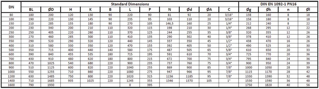
17 2 BN 70 en 17 8 Weights and dimensions Type BN3


18 18 2 BN 70 en Type BN6


19 2 BN 70 en 19 Type BN4
20 20 2 BN 70 en 9 Troubleshooting The disc does not shut tight Never close the disc by force. Irreparable damage may occur. Check if the energy supply is connected and switched on. Check if the actuator s closed position corresponds to the disc s closed position. Check the BN disc torque values using the following table (table 14). Check the disc s sealing surface and the elements for damage; take the disc out. Check if foreign bodies are stuck between disc and sealing elements. Remove foreign bodies or deposits if necessary. Replace damaged parts if necessary. Please refer to the chapter on dismounting the disc in the maintenance appendix. Please also refer to the chapter on Cleaning and maintenance in the maintenance appendix. Fluid or gas escapes from high performance butterfly valves with O-ring seals. Check if the O-rings on the bearing sleeve are damaged. If necessary, replace the O-rings of the bearing sleeve as well as the O-ring and supporting rings of the shaft seal (see fig. 21). Table 14 Valve size Maximum transmittable torque of the valve drive shaft in relation to the corresponding key width Maximum transmittable torque ShaftØ at valve Possible entrance Ø at actuator Bushing required Actuator [DN / inch] 80 / 3" /25/35/40 o/x B1J / 4" /25/35/40 o/x B1J / 6" /25/35/40 o/x B1J / 8" x B1J / 10" x B1J / 12" x B1J / 14" x B1J / 16" o B1J / 20" o B1J / 24" o B1J / 28" x B1J / 32" o B1J / 36" o B1J / 40" o B1J / 48" /105/120 o B1J / 56" /105/120 o B1J / 64" /105/120 o B1J-322 Fig. 21 O-ring seals Fluid or gas escapes at the cover plate Check if all cover screws are securely tightened. Replace the seal if necessary. 10 Safety instructions Please observe the following safety instructions during installation, maintenance work and operation of the high performance butterfly valve: 1. For safety reasons, it is not permissible to make modifications to the high performance butterfly valve s mode of operation or its actuator. 2. Only qualified personnel may carry out installation work on the high performance butterfly valve. 3. During the function test the energy supply may cause the high performance butterfly valve to move in an uncontrolled fashion. Therefore please ensure that the valve cannot move or even tilt, under any circumstances, during the function test. 4. Caution is advised when installing valves with safety position spring-to-open. If the disc protrudes from the valve in open position, the valve must be closed before installation (pneumatically, hydraulically etc.). Ensure that the energy supply is securely fastened and cannot be damaged or severed during installation under any circumstances. If the energy supply is interrupted suddenly, the valve will open abruptly. This may cause severe injuries and material damage. 5. During any maintenance work that is carried out, there is considerable risk of injury caused by accidental use of the remote control. If you plan to use a remote control during the work on the valve, an additional EMER- GENCY-STOP switch is required as a locking mechanism on the actuator. 6. Ensure that cleaning agents in combination with possible deposits in the high performance valve cannot cause any undesired chemical reactions. 7. If you need to carry out work in close proximity to the sealing surface of the disc, secure the disc with wooden wedges to eliminate the risk of crushing injuries. Take care that the sealing surface of the disc is not damaged in the process. 8. If a medium that is too hot damages the seals, the medium might escape at the shafts.
21 2 BN 70 en Maintenance 11.1 Cleaning and maintenance Although Metso s Mapag valves are designed to work under severe conditions, proper preventative maintenance can significantly help to prevent unplanned downtime and in real terms reduce the total cost of ownership. Metso recommends inspecting the valves regularly. The inspection and maintenance interval depends on the actual application and process condition. The inspection and maintenance intervals can be specified together with your local Metso experts. During this periodic inspection the parts detailed in the Spare Part Set/Sets should be replaced. Time in storage should be included in the inspection interval. Fig. 22 Location of sealing element If the medium carries contaminants that could impair the tightness of the valve, the sealing surfaces of the disc must be cleaned regularly. Contaminants may damage the sealing surface of the disc or the sealing element. Agents that could corrode the sealing surface or the elastomer seal must not be used under any circumstances. Use water, soapsuds or other liquid solvents and a soft lint-free cloth. CAUTION: Do not under any circumstances use pointy, abrasive or sharp tools (knives, files, screwdrivers etc.). And do not use any cleaning agents that might cause undesirable chemical reactions with the residues of the medium or might attack the sealing surface or the sealing element (320). NOTE: When sending goods to the manufacturer for repair, do not disassemble them. Clean the valve carefully and flush the valve internals. For safety reasons, inform the manufacturer of the type of medium used in the valve (include material safety datasheets (MSDS)). NOTE: In order to ensure safe and effective operation, always use original spare parts to make sure that the valve functions as intended. NOTE: For safety reasons, replace pressure retaining bolting if the threads are damaged, have been heated, stretched or corroded Preparation In order to avoid extended downtime periods during maintenance work, the appropriate spare part sets should be kept in store or ordered in time. Please take into account delivery and transport times. Before dismounting the valve, the following conditions must be met: Ensure that the pipelines are depressurised and free of process gases and fluids. Check that the disc valve has cooled down or warmed up sufficiently to eliminate any risks as a result of extreme temperatures. Find out what was the last medium to flow through the valve. There may be residues in the valve. Ensure that there is no danger of poisoning or chemical burns when coming into contact with those residues. Use adequate protective clothing, goggles and respiratory equipment if necessary. The operators safety instructions must be observed at all times. If you do not dismount the valve yourself, notify the qualified personnel of the risks and provide them with protective equipment if required. The valve must be closed during installation and dismounting in order to prevent potential damage Dismounting Please see section 3.5 of this IMO for instructions on dismounting.

22 22 2 BN 70 en 11.4 Reinstallation In order to reinstall the butterfly valve, please proceed as follows: Close the butterfly valve. At the end of the actuator shaft as well as the body there is a round marking. When reinstalling the valve, the two markings must be aligned. 1. Dismount the valve in the 0 -position (closed, see fig. 25) Please refer to chapter 3.5 of this IMO for instructions on dismounting the valve. 2. Place the valve securely on a solid base or workbench and ensure that it cannot slip or tilt. 3. Open the disc by turning the drive shaft counter-clockwise by 180 in order to access the sealing element (see fig. 26, disc swivelled by 180 ). Secure the disc, for example using wooden wedges, to eliminate the risk of squeezing or crushing. Make sure that the sealing surface of the disc is not damaged in the process. Fig. 23 Installation markings Set the actuator to the closed position. Make sure that the actuator is placed on the drive shaft in the correct position. Refer to the marking you made on the bracket and the actuator before dismounting the butterfly valve and align the markings across all elements (body bracket actuator) as precisely as possible. Install the butterfly valve between the pipe ends (see 4.3 and following chapters). Fig. 25 Disc in 0 -position 11.5 Replacing the sealing element In order to replace the sealing element, please proceed as follows: Fig. 26 Disc swivelled by 180 Fig. 24 Replacing the sealing element
.")

 and the seal ring (301) must be cleaned")


23 2 BN 70 en 23 For disc size 3-16 /DN in class Cl300/PN40 and 3 /80DN in Cl600/PN63 4. Remove the spiral retainer ring (310, see fig ). The seal ring (301) is now freely accessible and can be removed using an extraction tool (see fig. 29). For this purpose, the seal ring features two extraction threads. 5. The sealing element (320) and the O-ring seal (304) can now be replaced (see fig ). Before the new seals are mounted, the sealing groove (101) and the seal ring (301) must be cleaned carefully. In order to prevent damage to the seals, care is advised when replacing the seal ring. For disc sizes 3-12 /DN in class Cl300/PN40 and 3 /80DN in Cl 600/PN63 Lastly, insert the retainer ring (310). The retainer ring must be undamaged and free of any kinks. It must retain a clear spiral form following extraction; otherwise a new retainer ring must be used! Ensure that the retainer ring fits snugly into the groove along its entire circumference. It must not be possible to move the retainer ring in circumferential direction manually. Fig. 27 Loosening the retainer ring Fig. 30 Seal ring with O-ring Fig. 28 Removing the retainer ring Fig. 31 Replacing the sealing element Fig. 29 Extracting the seal Fig. 32 Replacing the sealing element


 Please refer to chapter 3.")
.")

24 24 2 BN 70 en For disc sizes 16, 20 /DN400, DN 500 in class Cl300/PN40 and all sizes in Cl600/PN63 except 3 /DN80 Put the retainer ring (310) and the clamping shoe (311) back in place. The retainer ring must be undamaged and free of any kinks; otherwise a new retainer ring must be used! Lock the bolt (313) using a new locking shim and additionally with Loctite 2701 and Activator 7471 (see item 3). Please note: Read the Loctite product instructions before use. 6. Check the high performance valve for tightness before reinstalling it. Refer to chapter 3.3 for installation instructions. 4. Release the clamping shoe with an open-ended or ring spanner (see fig. 35). The clamping shoe can then be extracted using a drift punch (see fig. 36). For disc sizes /DN and in class CL150/ PN10 to CL600/PN63 1. Dismount the valve in the 0 -position (closed, see fig. 33) Please refer to chapter 3.5 of this IMO for instructions on dismounting the valve. 2. Place the valve securely on a solid base or workbench and ensure that it cannot slip or tilt. 3. Open the disc by turning the drive shaft counter-clockwise by 180 in order to access the sealing element (see fig. 34, disc swivelled by 180 ). Secure the disc, for example using wooden wedges, to eliminate the risk of squeezing or crushing. Make sure that the sealing surface of the disc is not damaged in the process. Fig. 35 Releasing the clamping shoe Fig. 36 Extracting the clamping shoe Fig. 33 Disc in 0 -position 5. The retainer ring (301) is now freely accessible and can be released using a drift punch (see fig.37). Lift the retainer ring carefully from the groove (see fig.38 and 39). Now the seal ring is free and can be lifted out. Depending on the size it might be necessary to use a hoist to lift the ring. Fig. 34 Disc in 180 -position Fig. 37 Releasing the retainer ring using a drift punch

.")


. Fig.")


25 2 BN 70 en Unscrew the 4 bolts at the sealing flange (actuator shaftside) using, for example, a 19 mm ring or open-ended spanner (fig. 42). Screw the 4 bolts into the extra holes so that the sealing flange is pressed out of its seat (see fig. 43). The clamping plate that is held in place with a locking shim and screws can now be unscrewed and taken out (see fig. 44). Fig. 38 Lifting the retainer ring Fig. 42 Unscrewing the bolts on the sealing flange Fig. 39 Taking out the retainer ring Fig. 43 Pressing out the flange Fig. 40 Taking out the seal ring Fig. 44 Removing the clamping plate Fig. 41 Taking out the seal ring

. Fig.")


26 26 2 BN 70 en 7. Now the bolts on the cover side of the bearing can be unscrewed and trunnion and O-ring can be removed. Pull out the shaft and the thrust ring attached to it carefully. The Metaloplast bearing on the inside can now be replaced (see fig. 45 to 49). Fig. 48 Pushing the thrust ring off the shaft Fig. 45 Loosening the bolts Fig. 49 Replacing the Metaloplast bearing Fig. 46 Cover with O-ring 11.6 Maximum permissible closing torque for valves without actuator at 0 bar Table 15 Maximum permissible closing torque Torque Mc in Nm Pressure rating Valve size Closing torque Pressure rating Valve size Closing torque " / " / Fig. 47 Pulling out the shaft " / " / " / " / " / " / " / " / " / " / " / " / " / " /


 and the bracket (501) by unscrewing the hexagon-head bolts (502). 2. Swivel the disc by 180 to access the sealing element.")

27 2 BN 70 en 27 The torque may be diffused due to tolerances of the sealing element. The torque values apply to unlubricated sealing elements. The values must not be exceeded. If possible, the disc should also be tested with a differential pressure into the seat. Strongly deviating torque indicates impermissible bearing play or the sealing element not fitting correctly into the seat. Using a different sealing element might alleviate the problem in some cases Replacing worn parts In order to replace worn parts, please proceed as follows (see fig. 50 to fig. 58): 1. First remove the actuator (600) and the bracket (501) by unscrewing the hexagon-head bolts (502). 2. Swivel the disc by 180 to access the sealing element. Secure the disc, for example using wooden wedges, to eliminate the risk of squeezing or crushing. Make sure that the sealing surface of the disc is not damaged in the process. In order to prevent accidental damage to the sealing element, it is recommended to follow the sequence for dismounting the sealing element described in chapter Fig. 52 Disc in 180 -position Loosen the bolts (434) and remove the cover (430 and 437) on both sides of the valve. Actuator side: Fig bolts on the actuator side Fig. 50 Actuator bolts bracket Fig. 54 Actuator side without cover Fig. 51 Disc in 0 -position


, O-rings (471) and covers (430, 437).")
28 28 2 BN 70 en Bearing side: 4. Then remove the retaining O-ring (438) and pull the shaft from the disc and the body. Fig. 55 Cover on bearing side Fig. 58 Pulling out the shaft Fig. 56 Bearing side without cover 3. Insert an extraction tool into the extraction threads of the bearing sleeve and carefully pull out the bearing sleeve completely along the shaft that remains in the body. 5. All parts must be cleaned thoroughly before reassembly. 6. Check the shaft for traces of wear. In case of scoring or other damage it is strongly recommended to replace the shafts (401 and 402) as well! The shafts are not included in the spare part sets and must be ordered separately. 7. Reassembly is to be carried out in reverse order. For an easier fitting of the bearing sleeve, the O-rings (419, 471) may be lubricated using a special PTFE lubricant (check suitability of lubricant in advance!). In order to prevent any damage to the seals, fit the complete bearing sleeve (410) with utmost care. 8. Fit supporting rings (406), O-rings (471) and covers (430, 437). The cover screws 434) must be tightened using a torque spanner according to the torque values specified in chapter Check the tightness of the high performance valve before reinstalling it. Please refer to chapter 3.3 for installation instructions. Fig. 57 Pulling out the bearing sleeve
29 2 BN 70 en 29 The following parts can now be replaced using the recommended spare parts sets: O-ring Packing Qty/ Valve Description 1 Spare part set 1 419, 454, Spare part set 2a Seat set Spare part set 2b Bolt set 1 Spare part set 2c Bearing set 1 Spare part set 3 312, 313, , 432 Consists of 404, 420, 421, 422, 444, 446, 447, 448, 201, 301, 310, 311, 401, 403, 411, 430, 440, 453, 462* (* not with square end at shaft) Qty/ Valve Description 1 Spare part set 1 451, Spare part set 2a Seat set Spare part set 2b Bolt set 1 Spare part set 2c Bearing set 1 Spare part set 3 312, 313, , 432 Consists of 404, 407, 420, 421, 422, 444, 446, 447, 448, 452, , 301, 310, 311, 401, 403, 411, 430, 440, 450, 455, 456, 458, 462* (* not with square end at shaft) 11.8 Valve screws clamping torque Permissible clamping torque for steel group A and A4-70 steel group with regular metric thread in accordance with DIN 13, 70% utilisation of Rp 0.2, friction coefficient Table 16 Clamping torque Stressed cross section Stress 1) Force on shaft 1) Values correspond to 100% of the 0.2% yield strength Preload force Clamping torque Ø AS in mm 2 R p 0.2 in N R m in N N Nm M M M M M M M M M M M M M M
BALL VALVE MBV Series M1, M2 Installation, Maintenance and Operating Instructions
 BALL VALVE MBV Series M1, M2 Installation, Maintenance and Operating Instructions 1 M 70 en 12/2015 2 1 M 70 en Table of Contents 1 GENERAL...3 1.1 Scope of the manual...3 1.2 Valve construction...3 1.3
Mounting and Operating Instructions EB 8039 EN. Type 3351 Pneumatic On/off Valve. Type 3351 Pneumatic On/off Valve. Type 3351 Pneumatic On/off Valve
 Type 3351 Pneumatic On/off Valve Type 3351 Pneumatic On/off Valve Type 3351 Pneumatic On/off Valve Version with handwheel Mounting and Operating Instructions EB 8039 EN Edition May 2016 Definition of signal
KEYSTONE SERIES GRF RESILIENT SEATED BUTTERFLY VALVES INSTALLATION AND OPERATION MANUAL
 Before installation these instructions must be fully read and understood Intended valve use The valve is intended to be used only in applications within the pressure/temperature limits indicated in the
YOUR GLOBAL FLOW CONTROL PARTNER. BRAY/MCCANNALOK EN High Performance Butterfly Valve Operation and Maintenance Manual
 YOUR GLOBAL FLOW CONTROL PARTNER BRAY/MCCANNALOK EN High Performance Butterfly Valve TABLE OF CONTENTS 1.0 Definition of Terms....................................... 2 2.0 Introduction...........................................
FINETROL Eccentric rotary plug control valve. Installation, Maintenance and Operating Instructions
 FINETROL Eccentric rotary plug control valve Installation, Maintenance and Operating Instructions 5 FT 70 en 10/2016 2 5 FT 70 en Table of Contents 1 GENERAL...3 1.1 Scope of the manual...3 1.2 Valve construction...3
Operating Instructions Garlock Butterfly Valves DN : mm / 2-24
 Operating Instructions Garlock Butterfly Valves DN : 50-600 mm / 2-24 PN : 10 / 16 Type: GAR-SEAL SAFETY-SEAL STERILE-SEAL MOBILE-SEAL Conformity declaration... 14 0 Introduction... 15 1 Proper use...
Mounting and Operating Instructions EB 8222 EN. Type 3310/AT and Type 3310/3278 Pneumatic Control Valves. Type 3310 Segmented Ball Valve
 Type 3310/AT and Type 3310/3278 Pneumatic Control Valves Type 3310 Segmented Ball Valve Fig. 1 Type 3310/3278 with positioner Fig. 2 Type 3310/AT Mounting and Operating Instructions EB 8222 EN Edition
Keystone Series GR resilient seated butterfly valves GRW/GRL Installation and operation manual
 Before installation these instructions must be fully read and understood Important Before valves are installed or used the following actions are recommended. 1. Valves/parts have to be inspected and thoroughly
Mounting and Operating Instructions EB 8135/8136 EN. Series V2001 Valves Type 3535 Three-way Valve for Heat Transfer Oil
 Series V2001 Valves Type 3535 Three-way Valve for Heat Transfer Oil Type 3535 Three-way Valve with bellows seal and rod-type yoke (partial view) Mounting and Operating Instructions EB 8135/8136 EN Edition
NELES SOFT SEATED BUTTERFLY VALVE SERIES MAPAG BA FOR PSA PLANT ON/OFF AND CONTROL SERVICE
 NELES SOFT SEATED BUTTERFLY VALVE SERIES MAPAG BA FOR PSA PLANT ON/OFF AND CONTROL SERVICE Series Mapag BA is a wafer type butterfly valve with a one piece body and soft seat.. It is specially designed
NEOTECHA NTB-NTC BALL VALVES INSTALLATION AND MAINTENANCE INSTRUCTIONS
 Before installation these instructions must be fully read and understood 2 SAFETY Please also read through these notes carefully. 2.1 General potential danger due to: a. Failure to observe the instructions
Mounting and Operating Instructions EB 8111/8112 EN. Series V2001 Valves Type 3321 Globe Valve
 Series V2001 Valves Type 3321 Globe Valve Type 3321 Globe Valve with rod-type yoke and Type 3372 Electropneumatic Actuator (350 cm²) Mounting and Operating Instructions EB 8111/8112 EN Edition June 2013
MAPAG Butterfly valve - Type BK For cryogenic applications. Installation, Maintenance and Operating Instructions
 MAPAG Butterfly valve - Type BK For cryogenic applications Installation, Maintenance and Operating Instructions 2 BK 70 en 8/2010 2 2 BK 70 en Content 1 Method of operation... 3 2 Cleaning and maintenance...
USER INSTRUCTIONS. Kämmer SmallFlow / / SP Low and Micro Flow Valves. Installation Operation Maintenance
 User Instructions SmallFlow - KMENIM5000-02 02/15 USER INSTRUCTIONS Kämmer SmallFlow - 385000 / 385300 / 385000 SP Low and Micro Flow Valves FCD KMENIM5000-02 02/15 Installation Operation Maintenance Experience
BUTTERFLY VALVE WITH WELDED ENDS INSTALLATION AND MAINTENANCE MANUAL
 BUTTERFLY VALVE 31300 SERIES INSTRUCTIONS FOR INSTALLATION, USE AND MAINTENANCE 1. Overview Read these instructions carefully before starting the valve installation and start-up work. Safe keep the instructions
JT SERIES ANGLE STEM TANK BOTTOM BALL VALVE DN25 DN150. Installation, Maintenance and Operating Instructions
 JT SERIES ANGLE STEM TANK BOTTOM BALL VALVE DN25 DN150 Installation, Maintenance and Operating Instructions IMO-235 EN 3/2019 2 IMO-235 EN TABLE OF CONTENTS 1. GENERAL... 3 1.1 Scope of the Manual... 3
Storage, operating and maintenance instructions for AZ plug valves and Standard valves
 ARMATUREN Plug - Valves metallic with PTFE Sleeve 2-7 way Storage, operating and maintenance instructions for AZ plug valves and Standard valves Plug - Valves FEP/PFA - lined, 2-3 way Butterfly - Valves
back to main page Type: Butterfly valves Instructions and Operation Manual Warning! Warning! Danger for life! 1. Intended use Danger for life!
 Instructions and operation manual for butterfly valves This manual is intended to support the users of Herberholz butterfly valves type HRD/HRA, RD/RA, LDKE/LDKF for installation, operation and maintenance
NELES TRUNNION MOUNTED BALL VALVE, FULL BORE Series XH Installation, Maintenance and Operating Instructions
 NELES TRUNNION MOUNTED BALL VALVE, FULL BORE Series XH Installation, Maintenance and Operating Instructions 1 XH 70 en 2/2016 2 Table of Contents 1 GENERAL... 3 1.1 Scope of the manual... 3 1.2 Valve description...
FRP Ball Valves INSTALLATION & MAINTENANCE MANUAL
 FRP Ball Valves INSTALLATION & MAINTENANCE MANUAL FRP BALL VALVES TABLE OF CONTENTS MAINTENANCE AND INSTALLATION INSTRUCTIONS 1. 2. 2.1 2.2 2.3 2.4 GENERAL...Page 1 HANDLING...1 Receiving and Storing...1
These installation and maintenance instructions must be read in full and completely understood before the installation!
 These installation and maintenance instructions must be read in full and completely understood before the installation! 1. General information on the installation and maintenance instructions These instructions
Globe Valve Type Fig. 1 Type 3241 Globe Valve. Mounting and Operating Instructions EB EN
 Globe Valve Type 3241 Fig. 1 Type 3241 Globe Valve Mounting and Operating Instructions EB 8015-1 EN Edition July 2012 Contents Contents Page 1 Design and principle of operation.................... 4 2
V-port segment valves Series R1L Titanium Series R21L Titanium Series R2_S High consistency. Installation, Maintenance and Operating Instructions
 V-port segment valves Series R1L Titanium Series R21L Titanium Series R2_S High consistency Installation, Maintenance and Operating Instructions 3 R 71 en 9/2017 2 3 R 71 en Table of Contents 1 GENERAL...3
Ceramic Ball Valves. Series E2 and E6. Installation, Maintenance and Operating Instructions
 Ceramic Ball Valves Series E2 and E6 Installation, Maintenance and Operating Instructions 1 E2 70 en 2/2016 2 1 E2 70 en Table of Contents 1 GENERAL...3 1.1 Valve description...3 1.2 Valve markings...3
2.- HANDLING OF VALVES BEFORE ASSEMBLY 3.- FITTING THE VALVE TO THE REST OF THE ASSEMBLY 5.- PERIODICAL INSPECTION OF THE VALVE AND MAINTENANCE
 Page 1 of 16 CONTENTS 1.- INTRODUCTION 2.- HANDLING OF VALVES BEFORE ASSEMBLY 3.- FITTING THE VALVE TO THE REST OF THE ASSEMBLY 4.- OPERATION OF A BALL VALVE 5.- PERIODICAL INSPECTION OF THE VALVE AND
Mounting and Operating Instructions EB 8053 EN. Series 250 Type and Type Pneumatic Control Valves
 Series 250 Type 3252 1 and Type 3252 7 Pneumatic Control Valves Type 3252 High-pressure valve with Type 3277 Pneumatic Actuator and Type 3767 Electropneumatic Positioner Mounting and Operating Instructions
KEYSTONE OPTISEAL F14/16-15/17 AND BREWSEAL BUTTERFLY VALVES INSTALLATION AND MAINTENANCE INSTRUCTIONS
 Before installation these instructions must be fully read and understood 4. Ozone: storage rooms should not contain any equipment generating ozone. E.g. lamps, electric motors. IMPORTANT Before valves
Mounting and Operating Instructions EB 5868/5869 EN
 Electric Control Valves Types 3213/5857, 3213/5824, Types 3214/5824, 3214/3374, 3214/3274 with safety function: Types 3213/5825, 3214/5825, 3214/3374, 3214/3274 Pneumatic Control Valves Types 3213/2780-1,
Operating Instructions
 Operating Instructions Quadax Series Butterfly Valves (with actuator) Version September 2009 müller co-ax ag Gottfried-Müller-Str. 1 74670 Forchtenberg Germany Tel. +49 7947 828-0 Fax +49 7947 828-11 E-Mail
T R A N S L A T I O N Declaration of Conformity as per Directive 2014/68/EU
 T R A N S L A T I O N Declaration of Conformity as per Directive 2014/68/EU The manufacturer declares that: Pfeiffer Chemie-Armaturenbau GmbH, 47906 Kempen, Germany Butterfly valves BR14a, BR14b, BR14b-Type
Standard Valves Series Globe Valves Series Angle Valves Series Way-Valves
 Installation, Operation, Maintenance Instructions Standard Valves Series 035 000 Globe Valves Series 031 000 Angle Valves Series 033 000 3-Way-Valves 1 GENERAL INFORMATION These instructions are designed
Angle seat valve with piston actuator VZXA-...-K
 Angle seat valve with piston actuator VZXA-...-K Festo AG & Co. KG Postfach 73726 Esslingen Germany +49 711 347-0 www.festo.com 3 Further information Accessories www.festo.com/catalogue Spare parts www.festo.com/spareparts
NAF-Torex butterfly valves Maintenance and installation instructions List of spare parts
 NAF-Torex butterfly valves Maintenance and installation instructions List of spare parts Fi 41.42(4)GB 08.01 Contents SAFETY General 1 Lifting 2 Receiving inspection 3 Installation 4 Flange gaskets 5 Starting
Operating Instructions: Hand-operated, PTFE-lined butterfly valves, Series 22/23
 0 Introduction These instructions are intended to assist users of BRAY PTFE-lined butterfly valves, Series 22/23 in fitting, operating and servicing valves. Risks may arise and the manufacturer's warranty
Pressure relief valve
 Pressure relief valve Operating manual Series DHV 712 Version BA-2015.10.20 EN Print-No. 300 510 TR MA DE Rev001 ASV Stübbe GmbH & Co. KG Hollwieser Straße 5 32602 Vlotho Germany Phone: +49 (0) 5733-799-0
USER INSTRUCTIONS. Installation Operation Maintenance. Valtek Torex TX Control and shut-off valves. Butterfly Valves. Experience In Motion
 USER INSTRUCTIONS Valtek Torex TX Control and shut-off valves Butterfly Valves VLEEIM4143-02 09.10 Installation Operation Maintenance Experience In Motion Contents SAFETY General 1 Lifting 2 Receiving
Declaration of Conformity as per Directive 97/23/EC
 Declaration of Conformity as per Directive 97/23/EC The manufacturer declares that:, 47906 Kempen, Germany PTFE-lined Rotary plug valves Series 23e, with packing with lever for 90 operation with worm gear
Instructions for installation, operation and maintenance of: GATE VALVE
 Instructions for installation, operation and maintenance of: GATE VALVE GEN GAC GAF/GENF TERMOVENT SC Temerin Republic of Serbia Instruction for installation, operation and maintenance: Table of Contents
Angle seat valve with piston actuator VZXA-...-K
 Angle seat valve with piston actuator VZXA-...-K Instructions Operating (Translation of the original instructions) Festo AG & Co. KG Ruiter Straße 82 73734 Esslingen Germany +49 711 347-0 www.festo.com
When installing the screwed end, socket weld & flanged end valves the following respective procedures shall be followed for better performance.
 1. Storage LARSEN & TOUBRO LIMITED Page 1 of 5 1.1. All valves are to be stored in fully open position, in order to protect the sphere surface and soft valve seats. 1.2. Before shipping, the inlet and
Split Body Valves with Bellows Seal Series Globe Valves Series Angle Valves Series Way-Valves
 Installation, Operation, Maintenance Instructions Split Body Valves with Bellows Seal Series 025 300 Globe Valves Series 027 300 Angle Valves Series 028 300 3-Way-Valves 1 GENERAL INFORMATION These instructions
VSI, LLC SERIES 2100 RESILIENT SEATED BUTTERFLY VALVES INSTALLATION, OPERATION AND MAINTENANCE MANUAL
 VSI SERIES 2100 RESILIENT SEATED BUTTERFLY VALVES VSI, LLC. 2-0 SERIES 2100 RESILIENT SEATED BUTTERFLY VALVES INSTALLATION, OPERATION AND MAINTENANCE MANUAL Publication: V2100- August 2016 TABLE OF CONTENTS
Angle seat valve with diaphragm actuator VZXA-...-M
 Angle seat valve with diaphragm actuator VZXA-...-M Instructions Operating (Translation of the original instructions) Festo AG & Co. KG Ruiter Straße 82 73734 Esslingen Germany +49 711 347-0 www.festo.com
Installation and Operating Instructions
 Original Installation and Operating Instructions Hawle E2 Valve with Flange Outlet, System 2000 or PE Spigot Ends Table of Contents A) General...... 2 A1 Symbols..... 2 A2 Intended use... 2 A3 Labeling...
Keystone Butterfly valves ParaSeal Installation and maintenance instructions
 Before installation these instructions must be fully read and understood Please read these instructions carefully Hazard potentials: disregarding of instructions improper use of product insufficiently
CAPPING VALVE. Series PZ Installation, Maintenance and Operating Instructions
 CAPPING VALVE Series PZ Installation, Maintenance and Operating Instructions 8 PZ 70 en 4/2016 2 8 PZ 70 en Table of Contents 1 GENERAL...3 1.1 Scope of the manual...3 1.2 Valve construction...3 1.3 Valve
Mounting and Operating Instructions EB 8097 EN. Type and Type Pneumatic Control Valves
 Type 3347-1 and Type 3347-7 Pneumatic Control Valves Type 3347-7, cast body with welding ends Type 3347-7, bar stock body with threaded connections Mounting and Operating Instructions EB 8097 EN Edition
T R A N S L A T I O N Declaration of Conformity as per Directive 2014/68/EU
 T R A N S L A T I O N Declaration of Conformity as per Directive 2014/68/EU The manufacturer declares that: Pfeiffer Chemie-Armaturenbau GmbH, 47906 Kempen, Germany PFA/PTFE-lined ball valves BR20a, BR20b,
KEYSTONE Figure 990/991 Butterfly valves Installation, operation and maintenance instructions
 Before installation these instructions must be fully read and understood Potentially dangerous practices: disregarding instructions improper use of product use of insufficiently qualified personnel Application
INSTALLATION INSTRUCTION & TECHNICAL MANUAL FLOWMETER
 Sep 2003 INSTALLATION INSTRUCTION & SERIES: MICA (FL & RC) INSTALLATION INSTRUCTION & Type: MICA Series: MICA Page: INSTALLATION CONCEPT... 2 2 MOUNTING POSITION OF THE METER... 2 2. General remarks...
USER INSTRUCTIONS. NAF Trunnball DL Ball Valves. Installation Operation Maintenance. Experience In Motion FCD NFENIM A4 01/15
 USER INSTRUCTIONS NAF Trunnball DL Ball Valves FCD NFENIM4168-01-A4 01/15 Installation Operation Maintenance Experience In Motion Contents SAFETY 3 1 General 3 2 Lifting 4 3 Receiving Inspection 4 4 Installation
VAG CEREX M300 Butterfly Valve
 Operation and Maintenance Instructions VAG CEREX M300 Butterfly Valve KAT 1310-B Edition4 12-17 Table of Contents 1 General 3 1.1 Safety 3 1.2 Proper use 3 1.3 Identification 3 VAG reserves the right to
Pneumatic Cylinder Actuators Series B1C Installation, Maintenance and Operating Instructions
 Pneumatic Cylinder Actuators Series B1C Installation, Maintenance and Operating Instructions 6 BC 71 en 8/2017 2 6 BC 71 en Table of Contents 1 GENERAL...3 1.1 Scope of the manual...3 1.2 Structure and
Installation, Operation, and Maintenance Manual
 Industrial Process Installation, Operation, and Maintenance Manual Series PBFV Plastic Lined Butterfly Valve - Lug and Wafer Style Table of Contents Table of Contents Introduction and Safety...2 Safety
Control Valves Globe 3-way, Diverting & Mixing type Series GW Installation, Maintenance and Operating Instructions
 Control Valves Globe 3-way, Diverting & Mixing type Series GW Installation, Maintenance and Operating Instructions 4 GV 74 en 11/2013 2 4 GV 74 en Table of Contents 1 GENERAL...3 1.1 Scope of the manual...3
NEOTECHA NEOSEAL BUTTERFLY VALVE INSTALLATION AND MAINTENANCE INSTRUCTIONS
 Before installation these instructions must be fully read and understood 2 SAFETY Please also read through these notes carefully. 2.1 General potential danger due to: a. Failure to observe the instructions
KEYSTONE SERIES 320 BUTTERFLY VALVES INSTALLATION AND MAINTENANCE INSTRUCTIONS
 Before installation these instructions must be fully read and understood HAZARD POTENTIALS disregarding of instructions improper use of product insufficiently qualified personnel Valve application to be
Operating manual Separator
 Operating manual Separator Sheet no. AS/4.1.141.1.1 issue 20.08.2014 Contents Section Title Page 0 Introduction... 1 1 Intended use......1 2 Marking of the fitting... 1 3 Safety instructions... 2 4 Transport
Mounting and Operating Instructions EB 8091 EN. Pneumatic Control Valve Type and Type Type with 120 cm 2 actuator
 Pneumatic Control Valve Type 3510-1 and Type 3510-7 Type 3510-1 with 120 cm 2 actuator Type 3510-7 with 120 cm 2 actuator and integrated positioner Type 3510-1 with 60 cm 2 actuator Fig. 1 Pneumatic control
Operating Guide SBFV (PN16/25) ENGLISH Steel butterfly valve SBFV Page 2. Danfoss VI.IX.A1.02 1
 ENGLISH Steel butterfly valve SBFV Page 2. Danfoss VI.IX.A1.02 1") Operating Guide SBFV (PN16/25) ENGLISH Steel butterfly valve SBFV www.danfoss.com Page 2 Danfoss 2016.06 VI.IX.A1.02 1 Table of Contents: 1. OVERVIEW... 3 2. GENERAL... 3 2.1 Safety...3 2.2 Proper use...4
Operating Guide SBFV (PN16/25) ENGLISH Steel butterfly valve SBFV www.danfoss.com Page 2 Danfoss 2016.06 VI.IX.A1.02 1 Table of Contents: 1. OVERVIEW... 3 2. GENERAL... 3 2.1 Safety...3 2.2 Proper use...4
McCannalok HIGH PERFORMANCE BUTTERFLY VALVE OPERATION AND MAINTENANCE MANUAL. The High Performance Company
 McCannalok HIGH PERFORMANCE BUTTERFLY VALVE OPERATION AND MAINTENANCE MANUAL The High Performance Company Table of Contents Safety Information - Definition of Terms... 1 Introduction... 1 Installation...
Service and operating instruction Butterfly valves Edition: Nominal pressure PN Nominal size DN
 Service and operating instruction Mi-205 EN Butterfly valves Edition: 2014-02 Type MTV Wafer design Type MTVF Flanged design Nominal pressure PN 10-25 Nominal size DN 80-500 Edition: 2014-02 Original document
Maintenance and Service Instruction
 Screw pumps ACD Maintenance and Service Instruction This instruction is valid for all ACD pump models shown on page 2 Contents Page List of components 2 Exploded view/ordering code 3 Service intervals
Operating & Maintenance Manual For Steam Conditioning Valve
 For Steam Conditioning Valve 1 Table of Contents 1.0 Introduction 3 2.0 Product description 3 3.0 Safety Instruction 4 4.0 Installation and Commissioning 5 5.0 Valve Disassembly 6 6.0 Maintenance 6 7.0
Mounting and Operating Instructions EB EN. Type 3372 Electropneumatic Actuator. Actuator area: 120 and 350 cm² With Type 3725 Positioner
 Type 3372 Electropneumatic Actuator Actuator area: 120 and 350 cm² With Type 3725 Positioner Translation of original instructions Type 3372 with 120 cm² actuator area Type 3372 with 350 cm² actuator area
Installation, Operation, and Maintenance Manual
 Industrial Process Installation, Operation, and Maintenance Manual Cam-Tite Ball Valve Table of Contents Table of Contents Introduction and Safety...2 Safety message levels...2 User health and safety...2
ICV & ICVA Flanged Injection Control Valves 2 (DN 50) Type Installation, Maintenance and Operating Instructions
 Type Installation, Maintenance and Operating Instructions") ICV & ICVA Flanged Injection Control Valves 2 (DN 50) Type 1500 Installation, Maintenance and Operating Instructions IMO-282 EN 11/2017 2 IMO-282 EN TABLE OF CONTENTS 1. GENERAL... 2. INSTALLATION... 2.1
ICV & ICVA Flanged Injection Control Valves 2 (DN 50) Type 1500 Installation, Maintenance and Operating Instructions IMO-282 EN 11/2017 2 IMO-282 EN TABLE OF CONTENTS 1. GENERAL... 2. INSTALLATION... 2.1
METAL SEATED NELES ZEROLEAK NELDISC BUTTERFLY VALVES, SERIES L1 & L2
 METAL SEATED NELES ZEROLEAK NELDISC BUTTERFLY ALES, SERIES L & L Neldisc series L is a wafer type and series L a lug type metal seated high performance butterfly valve. With close to equal percentage characteristics
3-Way Flanged Ball Valves Series AM150FD & AM150FB Model A
 3-Way Flanged Ball Valves Series AM150FD & AM150FB Model A 2 (DN50) Class 150 Installation, Maintenance and Operating Instructions IMO-236 EN 3/2018 2 IMO-236 EN TABLE OF CONTENTS 1. GENERAL... 3 1.1 Scope
Power-Seal High Performance Butterfly Valve: Series P1 Installation & Maintenance Manual
 CAUTION: 1. For your safety read this manual completely before installation or servicing. 2. Before installing or servicing, please ensure the line pressure has been relieved, and any hazardous fluids
Installation, Operation and Maintenance Guide II NIBCO High Performance Butterfly Valves Series 6822 and 7822
 Installation, Operation and Maintenance Guide II NIBCO High Performance Butterfly Valves Series 6822 and 7822 Statements: NIBCO High Performance Butterfly Valves, Series 6822 and 7822, have been designed
Baumann 24000C Carbon Steel Little Scotty Control Valve Instructions
 Instruction Manual D103356X012 24000C Control Valve Baumann 24000C Carbon Steel Little Scotty Control Valve Instructions CONTENTS Introduction...1 Scope...1 Safety Precautions...1 Maintenance...2 Flow
5000/6000 SERIES BALL VALVES INSTALLATION - MAINTENANCE MANUAL
 Date: August 2011 / Page 1 of 6 5000/6000 SERIES BALL VALVES INSTALLATION - MAINTENANCE MANUAL DESIGN The design features three piece construction and a free floating ball allowing ease of maintenance
USER INSTRUCTIONS. Kämmer SmallFlow - Series / Low and Micro Flow Valves. Installation Operation Maintenance. Experience In Motion
 User Instructions SmallFlow 080/081000 - KMENIM8000-01 08/11 USER INSTRUCTIONS Kämmer SmallFlow - Series 080000 / 081000 Low and Micro Flow Valves FCD KMENIM8001-01 08/11 Installation Operation Maintenance
Installation and Operating Instructions for EAS -NC clutch Type 45_. _. _ Sizes 02 and 03
 Table of contents: Please read and observe this Operating Instruction carefully! A possible malfunction or failure of the clutch and any damage may be caused by not observing it. Page 1: - Table of contents
Installation, Operation, and Maintenance Manual
 Industrial Process Installation, Operation, and Maintenance Manual Series PBV Plastic Lined Ball Valve Table of Contents Table of Contents Introduction and Safety...2 Safety message levels...2 User health
IOM Manual. IOM Manual. Series 76/77.
 IOM Manual IOM Manual Series 76/77 www.flowlinevalves.com Flow Line Valve and Controls, L.L.C. 110 Main Project Road Schriever, LA 70395 P.O. Box 677 Schriever, LA 70395 Phone 985-414-6004 * Toll Free
PN9000 Series Pneumatic Actuators Installation and Maintenance Instructions
 3579049/14 IM-P357-29 CTLS Issue 14 PN9000 Series Pneumatic Actuators Installation and Maintenance Instructions PN9100 PN9200 1. Safety information 2. General product information PN9300 3. Installation
GT-200 GATE VALVES PN16, Screwed end
 Document No. : MD-QO-04-281 Date : 2009/07 /17 Version : 1.0 GT-200 GATE VALVES PN16, Screwed end USER MANUAL Modentic Industrial Corporation 14F-1,No.57Taya Rd.,Taichung,Taiwan,R.O.C. Email:modentic@ms9.hinet.net
3-Way Flanged Ball Valves 6, 8 & 10 (DN150, 200 & 250) Model D Series DM150FD 6 & 8 (DN150 & 200) Series DM150FB Model D
 Model D Series DM150FD 6 & 8 (DN150 & 200) Series DM150FB Model D") 3-Way Flanged Ball Valves 6, 8 & 10 (DN150, 200 & 250) Model D Series DM150FD 6 & 8 (DN150 & 200) Series DM150FB Model D Class 150 Installation, Maintenance and Operating Instructions IMO-238 EN 3/2018
3-Way Flanged Ball Valves 6, 8 & 10 (DN150, 200 & 250) Model D Series DM150FD 6 & 8 (DN150 & 200) Series DM150FB Model D Class 150 Installation, Maintenance and Operating Instructions IMO-238 EN 3/2018
Baumann 24000F Wafer Control Valve
 Instruction Manual 24000F Valves Baumann 24000F Wafer Control Valve Contents Introduction... 1 Scope of Manual... 1 Safety Precautions... 2 Maintenance... 2 Installation... 3 Air Piping... 3 Disassembly...
Installation Operation Maintenance. LSSN Butterfly Valve AGA Approved 50MM - 150MM. QAD#IM6055.REVA
 LSSN Butterfly Valve Installation Operation Maintenance Licence Number: 5326 www.challengervalves.com.au 1 Index 1. INTRODUCTION 1.1 Design Features 3 1.2 Flange and Pipe Compatibility 4 1.3 Operating
Scope. Applicability. Caution. I & M CV3000 Series. Storage. Installation & Maintenance Instructions for Marwin CV3000 Series Three Piece Ball Valves
 I & M CV3000 Series 3170 Wasson Road Cincinnati, OH 45209 USA Phone 513-533-5600 Fax 513-871-0105 marwin@richardsind.com www.marwinvalve.com Installation & Maintenance Instructions for Marwin CV3000 Series
Mounting and Operating Instructions EB 8048 EN. Type and Type Pneumatic Control Valves Type 3249 Aseptic Angle Valve
 Type 3249-1 and Type 3249-7 Pneumatic Control Valves Type 3249 Aseptic Angle Valve Ball body version Special version with packing Type 3249-7 Control Valve with Type 3277 Actuator and integrated positioner
KEYSTONE SERIES GR RESILIENT SEATED BUTTERFLY VALVES GRW/GRL INSTALLATION AND OPERATION MANUAL
 Before installation these instructions must be fully read and understood IMPORTNT Before valves are installed or used the following actions are recommended. 1. Valves/parts have to be inspected and thoroughly
INSTRUCTIONS FOR INSTALLATION, OPERATION AND MAINTENANCE OF
 INSTRUCTIONS FOR INSTALLATION, OPERATION AND MAINTENANCE OF Lift Check Valves according to European Norms [CLEN] Table of Contents 1. General safety information s 3 2. Product description 3 3. Transport
VSI INDUSTRIAL BALL VALVES SERIES 7100 SERIES 8100 SERIES 7200 SERIES 8300 SERIES 7400 SERIES 8400 SERIES 8000 SERIES 8500
 VSI INDUSTRIAL BALL BUTTERFLY VALVES VSI INDUSTRIAL BALL VALVES SERIES 7100 SERIES 8100 SERIES 7200 SERIES 8300 SERIES 7400 SERIES 8400 SERIES 8000 SERIES 8500 INSTALLATION, OPERATION AND MAINTENANCE MANUAL
3-Way Flanged Ball Valves Series AM150FD & AM150FB Model A 3 & 4 (DN80 & 100) Class 150. Installation, Maintenance and Operating Instructions
 Class 150. Installation, Maintenance and Operating Instructions") 3-Way Flanged Ball Valves Series AM150FD & AM150FB Model A 3 & 4 (DN80 & 100) Class 150 Installation, Maintenance and Operating Instructions IMO-237 EN 3/2018 2 IMO-237 EN TABLE OF CONTENTS 1. GENERAL...
3-Way Flanged Ball Valves Series AM150FD & AM150FB Model A 3 & 4 (DN80 & 100) Class 150 Installation, Maintenance and Operating Instructions IMO-237 EN 3/2018 2 IMO-237 EN TABLE OF CONTENTS 1. GENERAL...
Series 7000 Railroad, Standard Bore Flanged Ball Valves
 Series 7000 Railroad, Standard Bore Flanged Ball Valves Series 7150RR, 7300RR & 730SRR 3" 6" (DN 50 150) Class 150 & 3" (DN 50) Class 300 Installation, Maintenance and Operating Instructions IMO-R27 7/2016
Mounting and Operating Instructions EB 8097 EN. Pneumatic Control Valves Type and Type
 Pneumatic Control Valves Type 3347-1 and Type 3347-7 Hollow-mold cast body with welding ends Full-mold cast body with threaded connections Fig. 1 Type 3347-7 Control Valve with Type 3277 Actuator and integral
Baumann Sanitary Diaphragm Angle and Inline Control Valve
 Instruction Manual 84000 Valve Baumann 84000 Sanitary Diaphragm Angle and Inline Control Valve Contents Introduction... 1 Scope of Manual... 1 Safety Precautions... 2 Maintenance... 2 Flow Direction...
Butterfly valves Figure 56 Installation & Maintenance Instructions
 KEYSTONE Please read these instructions carefully This symbol indicates important messages and safety instructions. Hazard potentials: disregarding of instructions improper use of product insufficiently
Railroad Ball Valves Series 5REB3
 Railroad Ball Valves Series 5REB3 4" (DN 00) Installation, Maintenance and Operating Instructions IMO-R4 /05 IMO-R4 Table of Contents GENERAL.................................... 3. Scope of the Manual........................
Air Operated Diaphragm Pumps Operating and Maintenance Instructions
 Product & Chemical Disclaimer The user must take responsibility in the selection of the products materials of construction. Empire Pumps Ltd will act in an advisory role and offer recommendations; however,
ONYX VALVE CO MODEL DAO-PFC Installation & Maintenance
 ONYX VALVE CO MODEL DAO-PFC Installation & Maintenance OPERATION: (4-2010) The Onyx DAO-PFC pinch valve is an open frame valve without housing enclosure and fails closed on loss of air. The actuator drives
Mounting and Operating Instructions EB 8227 EN. Pneumatic Control Valve Type 3331/BR 31a Special version Type 3331/3278. Type 3331 Butterfly Valve
 Pneumatic Control Valve Type 3331/BR 31a Special version Type 3331/3278 Type 3331 Butterfly Valve Fig. 1 Type 3331/BR 31a (below) and Type 3331/3278 (top) Mounting and Operating Instructions EB 8227 EN
Mounting and Operating Instructions EB 8111/8112 EN. Valve Series V2001 Globe Valve Type 3321
 Valve Series V2001 Globe Valve Type 3321 Fig. 1 Type 3321 Valve with mounted rod-type yoke for pneumatic or electric actuators (partial view) Mounting and Operating Instructions EB 8111/8112 EN Edition
METSO NELES HIGH PERFORMANCE VALVE, METAL SEATED SERIES BW
 METSO NELES HIGH PERFORMANCE VALVE, METAL SEATED SERIES BW Neles BW series metal seated high performance butterfly valve with one piece body design, for both control and tight shut-off applications. Multiple
ONYX VALVE CO MODEL DAO-ADA Installation & Maintenance
 ONYX VALVE CO MODEL DAO-ADA Installation & Maintenance OPERATION: (4-2010) The Onyx DAO-ADA pinch valve is an open frame valve without housing enclosure and fails last position on loss of air. This actuator
INSTALLATION, OPERATION, MAINTENANCE MANUAL FOR MANUALLY OPERATED STOP CHECK VALVE
 INSTALLATION, OPERATION, MAINTENANCE MANUAL FOR MANUALLY OPERATED STOP CHECK VALVE Page 1 of 13 1.1 General CHAPTER 1 - GENERAL INFORMATION This manual contains maintenance instructions with pertinent